WO2017111063A1 - 転倒防止装置 - Google Patents
転倒防止装置 Download PDFInfo
- Publication number
- WO2017111063A1 WO2017111063A1 PCT/JP2016/088457 JP2016088457W WO2017111063A1 WO 2017111063 A1 WO2017111063 A1 WO 2017111063A1 JP 2016088457 W JP2016088457 W JP 2016088457W WO 2017111063 A1 WO2017111063 A1 WO 2017111063A1
- Authority
- WO
- WIPO (PCT)
- Prior art keywords
- article
- ceiling
- damper
- prevention device
- dampers
- Prior art date
- Legal status (The legal status is an assumption and is not a legal conclusion. Google has not performed a legal analysis and makes no representation as to the accuracy of the status listed.)
- Ceased
Links
Images



Classifications
-
- A—HUMAN NECESSITIES
- A47—FURNITURE; DOMESTIC ARTICLES OR APPLIANCES; COFFEE MILLS; SPICE MILLS; SUCTION CLEANERS IN GENERAL
- A47B—TABLES; DESKS; OFFICE FURNITURE; CABINETS; DRAWERS; GENERAL DETAILS OF FURNITURE
- A47B97/00—Furniture or accessories for furniture, not provided for in other groups of this subclass
-
- F—MECHANICAL ENGINEERING; LIGHTING; HEATING; WEAPONS; BLASTING
- F16—ENGINEERING ELEMENTS AND UNITS; GENERAL MEASURES FOR PRODUCING AND MAINTAINING EFFECTIVE FUNCTIONING OF MACHINES OR INSTALLATIONS; THERMAL INSULATION IN GENERAL
- F16F—SPRINGS; SHOCK-ABSORBERS; MEANS FOR DAMPING VIBRATION
- F16F9/00—Springs, vibration-dampers, shock-absorbers, or similarly-constructed movement-dampers using a fluid or the equivalent as damping medium
- F16F9/32—Details
- F16F9/54—Arrangements for attachment
-
- A—HUMAN NECESSITIES
- A47—FURNITURE; DOMESTIC ARTICLES OR APPLIANCES; COFFEE MILLS; SPICE MILLS; SUCTION CLEANERS IN GENERAL
- A47B—TABLES; DESKS; OFFICE FURNITURE; CABINETS; DRAWERS; GENERAL DETAILS OF FURNITURE
- A47B97/00—Furniture or accessories for furniture, not provided for in other groups of this subclass
- A47B2097/008—Anti-tip devices
-
- F—MECHANICAL ENGINEERING; LIGHTING; HEATING; WEAPONS; BLASTING
- F16—ENGINEERING ELEMENTS AND UNITS; GENERAL MEASURES FOR PRODUCING AND MAINTAINING EFFECTIVE FUNCTIONING OF MACHINES OR INSTALLATIONS; THERMAL INSULATION IN GENERAL
- F16F—SPRINGS; SHOCK-ABSORBERS; MEANS FOR DAMPING VIBRATION
- F16F2228/00—Functional characteristics, e.g. variability, frequency-dependence
- F16F2228/06—Stiffness
- F16F2228/066—Variable stiffness
-
- F—MECHANICAL ENGINEERING; LIGHTING; HEATING; WEAPONS; BLASTING
- F16—ENGINEERING ELEMENTS AND UNITS; GENERAL MEASURES FOR PRODUCING AND MAINTAINING EFFECTIVE FUNCTIONING OF MACHINES OR INSTALLATIONS; THERMAL INSULATION IN GENERAL
- F16F—SPRINGS; SHOCK-ABSORBERS; MEANS FOR DAMPING VIBRATION
- F16F9/00—Springs, vibration-dampers, shock-absorbers, or similarly-constructed movement-dampers using a fluid or the equivalent as damping medium
- F16F9/06—Springs, vibration-dampers, shock-absorbers, or similarly-constructed movement-dampers using a fluid or the equivalent as damping medium using both gas and liquid
- F16F9/061—Mono-tubular units
-
- F—MECHANICAL ENGINEERING; LIGHTING; HEATING; WEAPONS; BLASTING
- F16—ENGINEERING ELEMENTS AND UNITS; GENERAL MEASURES FOR PRODUCING AND MAINTAINING EFFECTIVE FUNCTIONING OF MACHINES OR INSTALLATIONS; THERMAL INSULATION IN GENERAL
- F16F—SPRINGS; SHOCK-ABSORBERS; MEANS FOR DAMPING VIBRATION
- F16F9/00—Springs, vibration-dampers, shock-absorbers, or similarly-constructed movement-dampers using a fluid or the equivalent as damping medium
- F16F9/32—Details
- F16F9/50—Special means providing automatic damping adjustment, i.e. self-adjustment of damping by particular sliding movements of a valve element, other than flexions or displacement of valve discs; Special means providing self-adjustment of spring characteristics
- F16F9/516—Special means providing automatic damping adjustment, i.e. self-adjustment of damping by particular sliding movements of a valve element, other than flexions or displacement of valve discs; Special means providing self-adjustment of spring characteristics resulting in the damping effects during contraction being different from the damping effects during extension, i.e. responsive to the direction of movement
Definitions
- the present invention relates to a fall prevention device.
- Patent Document 1 discloses a conventional fall prevention device.
- This overturn prevention device includes a damper and a pair of bases.
- the damper is attached between the upper surface of the furniture installed on the floor and the ceiling.
- the pair of base portions pivotally support each of both end portions of the damper so as to be rotatable around a rotation axis.
- One base part contacts the upper surface of the furniture, and the other base part contacts the ceiling.
- the fall prevention device rotates the damper around the rotation axis with respect to each base portion.
- abutted to the upper surface and ceiling of furniture can be maintained. Therefore, this fall prevention apparatus can make the damping force of a damper act on furniture, can suppress the inclination of furniture, and can prevent the fall of furniture.
- Patent Document 1 discloses an example in which one damper is installed between an article and a ceiling, but it may be desirable to attach two or more dampers.
- the work man-hours increase more than doubled due to the increase in the number of installations, so the burden on the worker accompanying the installation work is very high. growing.
- the same number of base portions as the number of dampers must be placed on the upper surface of the article, and a wide placement space must be ensured on the upper surface of the article. And it becomes difficult to apply to an article for which a sufficient placement space cannot be secured on the upper surface.
- the present invention has been made in view of the above-described conventional situation, and a plurality of dampers can be attached between the upper surface of the article and the ceiling, and an increase in work man-hours and an increase in installation space can be suppressed. Providing a fall prevention device that can be used is a problem to be solved.
- the fall prevention device of the present invention has a plurality of dampers attached between the upper surface of the article installed on the installation surface and the ceiling. As for the base part by the side of the articles
- the fall prevention device of the present invention has a plurality of dampers, and one end portion of each of the plurality of dampers is connected to the base portion on the article side.
- the fall prevention device is attached between the upper surface of the article and the ceiling, it is not necessary to separately provide a base portion for each damper on the article side, and the common base portion on the article side can also be used. For this reason, even if the number of dampers increases, the area of the upper surface of the article necessary for installing the base portion can be suppressed without increasing too much.
- a plurality of dampers can be integrated and managed by connecting the base part on the article side. When the base part is positioned and placed on the article, the base part is placed individually and positioned individually. This can save you time and effort.
- a plurality of dampers can be attached between the upper surface of the article and the ceiling, and an increase in work man-hours and an increase in installation space can be suppressed.
- a plurality of base portions on the ceiling side may be individually connected to the other end portions of the plurality of dampers.
- the ceiling side is installed by providing each damper individually.
- the degree of freedom in the above can be increased.
- the base portion on the article side that is restricted by the upper surface size, shape, and the like of the article can be configured to be easily adapted to the restriction by the article by making common.
- the position of the base portion can be set for each damper so that fine adjustment can be performed.
- any or all of the plurality of dampers may be connected to different positions on the other base portion on the common ceiling side. According to this configuration, it is possible to reduce the number of parts on the ceiling side by sharing the base portion, and it is possible to suppress an increase in work man-hours.
- the ceiling-side bases are respectively disposed on both sides of a vertical imaginary line passing through the center of the article-side base portion in a state of being attached between the upper surface of the article and the ceiling. May be.
- one damper is attached in a form inclined to one side of the imaginary line with respect to the base part on the article side, and the other damper is attached in a form inclined to the other side. According to this configuration, whether the article is tilted to one side or the other side, the force for tilting the article can be effectively attenuated and the tilt of the article can be suppressed.
- the inclination of the damper arranged on one side of the virtual line with respect to the vertical direction and the inclination of the damper arranged on the other side of the virtual line with respect to the vertical direction may be the same. According to this configuration, both the inclination of the article toward one side and the inclination toward the other side can be attenuated with a good balance.
- the bottom of the article may have a longitudinal shape in which a predetermined direction orthogonal to the height direction of the article is the longitudinal direction.
- the center position of the bottom portion and the arrangement range of the base portion on the article side may overlap in the orthogonal direction orthogonal to the height direction and the longitudinal direction of the article.
- the article tends to tilt in a direction orthogonal to the longitudinal direction of the bottom, and the lift due to the tilt tends to occur at both ends of the bottom in the orthogonal direction.
- Embodiment 1 that embodies the fall prevention device of the present invention will be described with reference to the drawings.
- At least one or more fall prevention devices 1 are attached between the upper surface A ⁇ b> 1 of the furniture F and the ceiling C.
- the furniture F is placed on the floor surface Fr so that the article does not face the front surface portion F1 and the back surface portion F2.
- the furniture F has a rectangular parallelepiped shape, has a door (not shown), a drawer, and the like on the front surface (the right side surface in FIG. 1), and has a structure that can store clothes, accessories, and the like inside.
- the furniture F has a rectangular shape with a horizontal cross section that is long in the left-right direction (the depth direction in FIG. 1).
- the outer diameter shape of the furniture F in plan view is a rectangular shape.
- the longitudinal direction (long side direction in the rectangular shape) is the left-right direction of the furniture F (article), and the short side direction (short side direction in the rectangular shape) is the furniture F (article).
- the front-rear direction is a direction orthogonal to the left-right direction and the front-rear direction.
- the bottom B2 of the furniture F also has a bottom surface A2 having a longitudinal shape.
- the outer diameter shape (the outer edge shape when viewed from below) of the bottom surface A2 is a rectangular shape.
- the overturn prevention device 1 includes a plurality of dampers 10, an article-side base 30 ⁇ / b> A, and a ceiling-side base 30 ⁇ / b> B, 30 ⁇ / b> C.
- the two dampers 10 have the same structure.
- the damper 10 has a cylinder 11, a rod guide (not shown), a piston (not shown), a rod (rod) 13, and two joints 15 provided at both ends.
- the cylinder 11 has a bottomed cylindrical shape.
- the rod guide seals the opening of the cylinder 11.
- the piston is slidably inserted into the cylinder 11.
- the rod 13 has a base end connected to the piston. Further, the rod 13 is inserted through the rod guide, and the tip side protrudes to the outside of the cylinder 11.
- the cylinder 11 encloses hydraulic oil and compressed gas (gas).
- each joint portion 15 is formed by bending a flat metal fitting.
- Each joint portion 15 is connected to the bottom of the cylinder 11 and the tip of the rod 13.
- Each joint portion 15 is formed with a through hole 15 ⁇ / b> A penetrating in a direction orthogonal to the axis of the damper 10.
- Both the two dampers 10 are pressure dampers in which the damping force generated during the extension operation is smaller than the damping force generated during the contraction operation.
- the extension operation of the damper 10 means an operation in which the protruding length of the rod 13 from the cylinder 11 and the length of the damper 10 become longer.
- the contraction operation of the damper 10 means an operation in which the protruding length of the rod 13 from the cylinder 11 and the length of the damper 10 become shorter.
- the expansion force of the compressed gas sealed in the cylinder 11 works in the extending direction.
- the mechanism (mechanism) in which the damping force of the damper 10 is generated is a well-known structure, and will not be described.
- the cylinder 11 is partitioned into a rod-side pressure chamber in which the base end portion of the rod 13 is housed and an anti-rod-side pressure chamber by a piston inside.
- the piston is formed with an orifice which is a throttle valve for communicating between the two pressure chambers.
- the orifice functions as a damping force generator that generates a damping force by applying resistance to the flow of hydraulic oil between the rod-side pressure chamber and the non-rod-side pressure chamber accompanying the expansion / contraction operation of the damper 10.
- the piston is formed with a communication passage that communicates between the pressure chambers via a check valve.
- the check valve allows the flow of hydraulic oil from the rod side pressure chamber to the anti rod side pressure chamber, and prevents the reverse flow. For this reason, when the damper 10 is extended, the flow path of the hydraulic oil from the rod-side pressure chamber to the anti-rod-side pressure chamber becomes a path between the orifice and the communication path. On the other hand, in the damper 10, during the contracting operation, the flow path of the hydraulic oil from the non-rod side pressure chamber to the rod side pressure chamber is only the orifice. For this reason, the damping force generated during the extension operation of the damper 10 is smaller than the damping force generated during the contraction operation.
- the base part 30A on the article side placed on the upper surface A1 of the furniture F is connected to both end parts on one side of the two dampers 10.
- Joint portions 15 are connected to the bottoms of the cylinders 11 of the two dampers 10, and these joint portions 15 are rotatably connected to the article-side base portion 30A.
- the article-side base portion 30A includes a base portion main body 131, a bolt 145 and a nut 147, which are rotating shaft members, a bush 135, and a non-slip portion 137.
- the base portion main body 131 In a plan view of the article-side base portion 30A as viewed from above with the furniture F placed in contact with the upper surface of the furniture F, the base portion main body 131 has a rectangular outer shape.
- the direction in which the long side extends in the outline of the base body 131 in plan view is referred to as “long side direction”, and the direction in which the short side extends is referred to as “short side direction”.
- the base portion main body 131 is linearly parallel to the upper surface of the furniture F in a side view when the article-side base portion 30A is viewed in the short side direction while being placed in contact with the upper surface of the furniture F.
- the upper end edge is an arcuate outer shape that swells upward from both sides of the lower end edge (see FIG.
- the base body 131 has a substantially trapezoidal shape in which the upper end edge is shorter than the lower end edge in a side view of the article-side base portion 30A in the long side direction in a state of being placed in contact with the upper surface of the furniture F. It is an outer shape (see FIGS. 2 and 3).
- the base portion main body 131 has a groove portion 141 extending in the long side direction (the left-right direction in FIG. 1 and the depth direction in FIGS. 2 and 3) on the upper surface.
- the groove 141 is configured such that the bottom surface 141A is substantially parallel to the contact surface with the article (the bottom surface of the anti-slip portion 137), and the inner wall surface 141B rises substantially perpendicular to the bottom surface 141A on both sides of the bottom surface 141A.
- the groove portion 141 has a constant width except for portions where convex portions 143, 144, and 146 described later are formed.
- the groove portion 141 is formed with a pair of convex portions 143 and 146 protruding from the bottom surface 141A of the groove portion 141 and the inner wall surfaces 141B and 141B at the center portion in the long side direction. Between the convex portions 143 and 146, a convex portion 144 protruding upward from the bottom surface 141A is formed. These convex portions 143, 144, and 146 are formed with spaces in which the joint portion 15 of the damper 10 and a bush 135 described later are fitted between the convex portions. This space communicates with the groove 141.
- the interval between the inner wall surfaces of the convex portions 143 and 144 is slightly larger than the length of the bush 135 described later.
- the distance between the inner wall surfaces of the convex portions 144 and 146 is slightly larger than the length of the bush 135.
- insertion holes 143B, 144B, 146B through which a shaft portion 145B of a bolt 145 described later is inserted are formed in a shape penetrating in the short side direction.
- the base part main body 131 is a central part in the long side direction, and recessed parts 142 are formed on both sides of the groove part 141. These hollow portions 142 are opened outward in the upward direction and the short side direction. These recesses 142 have respective insertion holes 143B and 146B that open through the convex portions 143 and 146, respectively, open on the side surfaces. Further, an insertion hole 144B is formed in the central convex portion 144, and the bolt 145 can be inserted into the insertion holes 143B, 144B, 146B of the convex portions 143, 144, 146. .
- a head 145A of the bolt 145 and a nut 147 screwed into the bolt 145 are arranged. These recesses 142 are formed so as to spread upward in the long side direction so that a tool can be fitted from above to the head 145A and the nut 147 of the bolt 145.
- the bolt 145 is inserted into the insertion holes 143B, 144B, 146B of the convex portions 143, 144, 146 from one side of the base portion main body 131, and on the other side of the base portion main body 131, a nut is attached to the shaft portion 145B of the bolt 145. 147 is screwed.
- the central axis of the bolt 145 becomes the rotation axis of the two dampers 10. That is, the two dampers 10 rotate about the same rotation axis.
- the inside of the base portion main body 131 is formed in a hollow shape, and is formed by crossing a plurality of ribs (rib) extending in parallel in the short side direction and a plurality of ribs extending in parallel in the long side direction. ing.
- the bush 135 is substantially cylindrical as shown in FIG.
- the bush 135 is an elastic body.
- the length of the bush 135 is slightly smaller than the distance between the inner wall surfaces of the protrusions 143, 144, 146 provided on the base body 131.
- the bush 135 is formed with a recess 135 ⁇ / b> A that goes around the outer peripheral surface of the central portion.
- the outer diameter of the recess 135A is substantially equal to the inner diameter of the through hole 15A formed in the joint portion 15 of the damper 10.
- the outer diameter of the portion of the bush 135 rising from both ends of the recess 135 ⁇ / b> A is larger than the inner diameter of the through hole 15 ⁇ / b> A formed in the joint portion 15 of the damper 10.
- the bush 135 has outer peripheral surfaces 135B at both ends that are reduced in diameter outwardly. For this reason, the bush 135 is inserted into the through hole 15A formed in the joint portion 15 of the damper 10 while being elastically deformed. The bush 135 is attached to the joint portion 15 of the damper 10 with the recess 135A fitted in the through hole 15A.
- the inner diameter of the bush 135 is slightly larger than the outer diameter of the shaft 145B of the bolt 145. Further, the bush 135 has inner peripheral surfaces 135C at both ends that are expanded in the outward direction. For this reason, the bush 135 is rotatable around the shaft portion 145B of the bolt 145. Further, the bush 135 can be tilted with respect to the shaft portion 145B of the bolt 145 in a range where the inner peripheral surfaces 135C of both end portions whose diameters have been expanded come into contact with the outer peripheral surface of the shaft portion 145B of the bolt 145.
- the damper 10 having the bush 135 attached to the joint portion 15 is rotatable around the shaft portion 145B of the bolt 145 and is swingable in a direction crossing the rotation direction. Specifically, the rocking occurs due to the dimensional allowance and the diameter increase of the inner peripheral surface 135C. Further, the elastic deformation of the bush 135 allows the damper 10 to swing more greatly in the direction crossing the rotation direction.
- the non-slip portion 137 has a similar (rectangular) outer shape slightly larger than the outer shape of the base body 131.
- the anti-slip portion 137 is made of rubber. Further, the anti-slip portion 137 is fitted into the lower end opening of the base portion main body 131 in the article-side base portion 30 ⁇ / b> A in a state of being placed in contact with the upper surface of the furniture F. Moreover, the anti-slip
- the non-slip portion 137 has a flat surface that comes into contact with the upper surface A1 of the furniture F, and a surface facing the opposite side (a surface facing the base portion main body 131) is an outer peripheral wall of the base portion main body 131 and an internal rib. A fitting groove adapted to the above is formed.
- the anti-slip portion 137 is detachably attached to the base portion main body 31 by its elastic force.
- the base portions 30B and 30C on the ceiling side have the same structure. Therefore, in the following, the ceiling-side base portion 30B will be described in detail, and the ceiling-side base portion 30C will not be described in detail because it has the same structure as the ceiling-side base portion 30B.
- the base part 30 ⁇ / b> B on the ceiling side includes a base part body 31, bolts 45 and nuts 47, bushes 35, and anti-slip parts 37.
- the base portion body 31 of the base portion 30B on the ceiling side is in a direction parallel to the contact surface on the opposite side to the contact surface to the ceiling (contact surface of the anti-slip portion 37) and in a direction perpendicular to the central axis of the bolt 45.
- An elongated groove 41 is formed.
- the groove portion 41 is provided with a bottom surface 41A in parallel with a contact surface to the ceiling (contact surface of the anti-slip portion 37), and an inner wall surface 41B is provided substantially vertically on both sides of the bottom surface 41A.
- the groove portion 41 is formed to have a constant width except for a portion where the pair of convex portions 43 and 43 are formed.
- the groove portion 41 is formed with a pair of convex portions 43, 43 protruding from the bottom surface 41A of the groove portion 41 and the inner wall surfaces 41B, 41B at the center in the long side direction.
- a space in which the joint portion 15 of the damper 10 and a bush 35 described later are fitted is formed between the convex portions 43 and 43, and the space communicates with the groove portion 41.
- the distance between the inner wall surfaces 43A, 43A of the pair of convex portions 43, 43 (the length in the short side direction of the space) is slightly larger than the length of the bush 35 described later.
- the pair of convex portions 43 and 43 has an insertion hole 43B through which the shaft portion 45B of the bolt 45 is inserted in the short side direction.
- the base portion main body 31 is formed with depressions 42 at the center in the longitudinal direction of the base portion main body 31 and on both sides of the groove portion 41.
- the insertion hole 43B which penetrated the convex part 43 has opened to the side surface.
- a head 45A of a bolt 45 described later and a nut 47 screwed into the bolt 45 are arranged in the recess 42.
- the recess 42 has a widened shape so that a tool can be fitted to the head 45 ⁇ / b> A of the bolt 45 and the nut 47.
- the central axis of the bolt 45 is a rotation axis of the damper 10 in the base portions 30B and 30C on the ceiling side.
- the bush 35 is substantially cylindrical and is an elastic body.
- the length of the bush 35 is slightly smaller than the interval between the inner wall surfaces 43A and 43A of the pair of convex portions 43 and 43 provided on the base portion main body 31.
- the bush 35 is formed with a recess 35 ⁇ / b> A that goes around the outer peripheral surface of the central portion.
- the outer diameter of the recess 35 ⁇ / b> A is substantially equal to the inner diameter of the through hole 15 ⁇ / b> A formed in the joint portion 15 of the damper 10.
- the outer diameter of the portion of the bush 35 rising from both ends of the recess 35 ⁇ / b> A is larger than the inner diameter of the through hole 15 ⁇ / b> A formed in the joint portion 15 of the damper 10.
- the inner diameter of the bush 35 is slightly larger than the outer diameter of the shaft part 45B of the bolt 45. Further, the bush 35 has inner peripheral surfaces 35C at both ends that are expanded in the outward direction. For this reason, the bush 35 is rotatable around the shaft portion 45 ⁇ / b> B of the bolt 45. Further, the bush 35 can be inclined with respect to the shaft portion 45B of the bolt 45 as long as the inner peripheral surfaces 35C of both end portions whose diameters have been expanded come into contact with the outer peripheral surface of the shaft portion 45B of the bolt 45. That is, the damper 10 having the bush 35 attached to the joint portion 15 is rotatable around the shaft portion 45B of the bolt 45 and is swingable in a direction crossing the rotation direction. Specifically, the rocking occurs due to the dimensional allowance and the diameter increase of the inner peripheral surface 35C. Furthermore, the elastic deformation of the bush 35 allows the damper 10 to swing more greatly in the direction crossing the rotational direction.
- the non-slip portion 37 has a similar (rectangular) outer shape slightly larger than the outer shape of the base portion main body 31.
- the non-slip portion 37 is made of rubber and is a substantially flat plate.
- the anti-slip portion 37 is detachably attached to the base portion main body 31 by its elastic force.
- the fall prevention device 1 configured in this way is attached between the upper surface A1 and the ceiling C of the furniture F (article) installed on the floor surface Fr (installation surface), for example, as shown in FIGS. It is done.
- both end portions on one side of the two dampers 10 are coupled to the base part 30 ⁇ / b> A on the article side, and the base part 30 ⁇ / b> A on the article side is also used as a base for both dampers 10.
- two ceiling-side base portions 30B and 30C are individually connected to the other end portions of the two dampers 10, respectively.
- the fall prevention device 1 is attached between the upper surface A ⁇ b> 1 of the furniture F (article) and the ceiling C, and the vertical direction passing through the center portion of the article-side base portion 30 ⁇ / b> A.
- the base portions 30B and 30C on the ceiling side are arranged on both sides of the virtual line L1, respectively.
- the damper 10 disposed on one side of the imaginary line L1 (the damper 10 connected to the base portion 30B) is disposed with an inclination such that an angle formed between the central axis of the damper 10 and the vertical direction is ⁇ .
- the damper 10 disposed on the other side of the imaginary line L1 (the damper 10 connected to the base portion 30C) is also disposed with an inclination where the angle between the central axis of the damper 10 and the vertical direction is ⁇ . That is, both the dampers 10 have the same inclination with respect to the vertical direction, and one of the dampers 10 is disposed so as to fall to the front side (an inclined state that becomes a front position as it goes upward).
- the other damper 10 is arranged in a shape that falls to the rear side (an inclined state that becomes a rear position as it goes upward).
- the bottom B2 of the furniture F (article) has a longitudinal shape (specifically, a bottom view) in which a predetermined direction (the above-described left-right direction) orthogonal to the height direction of the furniture F is the longitudinal direction. (Rectangular shape). For this reason, when the furniture F is placed on the floor surface Fr, the furniture F is easily placed in a short direction (the above-described front-rear direction) perpendicular to the height direction and the longitudinal direction.
- the fall prevention device 1 has the center position P1 of the bottom portion B2 and the arrangement range AR1 of the base portion 30A on the article side in the front-rear direction of the furniture F (the orthogonal direction perpendicular to the height direction and the longitudinal direction). overlapping. That is, the center position P1 is located directly below the article-side base portion 30A.
- FIG. 7 simply shows the positional relationship between the article-side base portion 30A and the bottom B2 when the article-side base portion 30A and the furniture F are viewed in plan, and the outer edge shape of the article-side base portion 30A.
- the outer edge shape of the bottom B2 is simply shown.
- the position of the outer edge of the bottom B2 is virtually indicated by a one-dot chain line.
- the center position P1 in the front-rear direction of the bottom B2 is located directly below the base 30A on the article side. More specifically, the position of the center axis of the bolt 145 (that is, the rotation of the damper 10).
- the position directly below (center) is the center position P1 in the front-rear direction of the bottom B2.
- the fall prevention device 1 is installed on the floor surface Fr when the furniture F tilts in the direction in which the axis of the pressure damper 10 extends, that is, the front-rear direction of the furniture F, due to the shaking of the earthquake or the like.
- the pressure damper 10 attached between the upper surface A1 of the furniture F and the ceiling C contracts.
- this fall prevention apparatus 1 can be attached also to the furniture F which is not installed near the wall surface which stood
- the plurality of dampers 10 can be installed with a sufficient angle of inclination.
- the overturn prevention device 1 has a plurality of dampers 10, and one end portions of the plurality of dampers 10 are all connected to the article-side base portion 30 ⁇ / b> A.
- the fall prevention device 1 is attached between the upper surface A1 of the furniture F (article) and the ceiling C, it is not necessary to provide a base portion for each damper 10 on the furniture F side.
- the base portion 30A can also be used. For this reason, even if the number of dampers increases, the area of the upper surface of the article necessary for installing the base portion can be suppressed without increasing too much.
- the plurality of dampers 10 can be integrally managed by being connected by the base part 30A on the article side, and when the base part is positioned and placed on the article, the base part is placed individually and individually. It is possible to save the trouble of positioning. In addition, since the number of base parts can be reduced, the number of assembling steps and costs can be reduced.
- a plurality of dampers 10 can be attached between the upper surface A1 of the furniture F (article) and the ceiling C, and an increase in work man-hours and an increase in installation space can be suppressed.
- a plurality of ceiling-side base portions 30B and 30C are individually connected to the other end portions of the plurality of dampers 10 (end portions opposite to the article-side base portion 30A side). Yes.
- the degree of freedom in installation can be increased.
- the base portion on the article side that is restricted by the upper surface size, shape, and the like of the article can be configured to be easily adapted to the restriction by the article by making common.
- the position of the base portion can be set for each damper so that fine adjustment can be performed.
- the fall prevention device 1 is attached between the upper surface A1 of the furniture F (article) and the ceiling C, and is provided on both sides of the virtual line L1 in the vertical direction passing through the central portion of the base portion 30A on the article side.
- Base portions 30B and 30C are arranged.
- the center position in the long side direction and the center position in the short side direction of the base part 30A on the article side are the center part.
- the virtual line L1 intersects the central axis of the bolt 145 in the vertical direction. It is a virtual straight line.
- one damper 10 is attached in a form tilted to one side of the imaginary line L1 with respect to the base part 30A on the article side, and the other damper 10 is attached in a form tilted to the other side.
- the force for tilting the furniture F can be effectively attenuated and the tilt of the furniture F can be suppressed. The same effect occurs even when the furniture F is another article.
- the inclination of the damper 10 arranged on one side of the virtual line L1 with respect to the vertical direction and the inclination of the damper 10 arranged on the other side of the virtual line L1 with respect to the vertical direction are the same. According to this configuration, both the inclination of the furniture F to one side and the inclination to the other side can be attenuated with a good balance.
- the bottom B2 of the furniture F has a longitudinal shape in which a predetermined direction (left-right direction) orthogonal to the height direction of the furniture F is a longitudinal direction.
- the center position of the bottom B2 and the arrangement range of the base part 30A on the article side overlap in the front-rear direction of the furniture F (the direction perpendicular to the height direction and the longitudinal direction of the bottom B2). . That is, the center position in the front-rear direction of the bottom B2 is directly below the article-side base 30A.
- the furniture F tends to be inclined in a direction (front-rear direction) orthogonal to the longitudinal direction (left-right direction) of the bottom B2, and the ends of the bottom B2 in the orthogonal direction (that is, the front end and the rear end) are caused by the inclination. Lifting is likely to occur. For this reason, if it is set as the structure by which the center position (center position of the front-back direction in the furniture F) is arrange
- the fall prevention device 201 of the second embodiment is different from the first embodiment in that a plurality of ceiling-side base portions 30B and 30C (FIG. 1 and the like) provided in the first embodiment are integrated into a common ceiling-side base portion 230B. Unlike this, the second embodiment is the same as the first embodiment. Therefore, about the same part as the fall prevention device 1 of Embodiment 1, the same code
- the fall prevention device 201 of this configuration has a common ceiling in which the other end of the two dampers 10 (the end opposite to the article-side base 30 ⁇ / b> A) is common.
- the base portions 230B on the side are connected to different positions.
- the connection structure between the base part main body 231 and the two dampers 10 in the common ceiling-side base part 230B is the same as the connection structure between the two base part main bodies 31 and the two dampers 10 in the first embodiment.
- the common ceiling-side base portion 230B shown in FIGS. 8 and 9 includes two convex portions 43 and two insertion holes formed in the ceiling-side base portion 30B (FIGS. 2, 5, etc.) of the first embodiment. Two convex portions 43 and two insertion holes 43B are provided in the same positional relationship as 43B. Further, the ceiling-side base portion 230B has the same positional relationship as the two convex portions 43 and the two insertion holes 43B (FIGS. 2, 5, etc.) formed in the ceiling-side base portion 30C of the first embodiment.
- Two convex portions 43 and two insertion holes 43B are provided.
- the two sets of the combination of the bolt 45 and the nut 47 are in the same positional relationship as the two sets of the combination of the bolt 45 and the nut 47 in the first embodiment. Is provided. With such a structure, the shaft portions 45B of the two bolts 45 are positioned in parallel, and the centers of the shaft portions 45B serve as the rotational shafts of the dampers 10.
- the part 15 can be pivotably attached.
- the anti-slip portion 237 is made of rubber and is substantially flat, and has a similar (rectangular) outer shape that is larger than the base portion main body 231.
- the anti-slip portion 237 is detachably attached to the base portion main body 231 by its elastic force.
- FIG. 8 the holding structure in the base part 230B of the common ceiling side was illustrated.
- the holding structure at the base portion 230B on the ceiling side is merely an example, and both end portions on the other side of the two dampers 10 can be rotatably held. Any configuration may be used as long as the central axis of rotation) is determined in parallel and at regular intervals.
- one end of the two dampers 10 is rotatably held by a common shaft member (bolt 145) in the article-side base 30A.
- the damper 10 is rotatable about a common rotation axis.
- the other end portions of the two dampers 10 are rotatably held by different shaft members (two bolts 45) in the common ceiling-side base portion 230B, and the respective dampers 10 are separately rotated. It can be rotated around a moving axis (parallel rotation axis).
- the fall prevention device 201 shown in FIG. 8 is attached between the upper surface A1 of the furniture F and the ceiling C, and a vertical imaginary line L1 passing through the center of the article-side base portion 30A (of the first embodiment).
- the other end portions of the respective dampers 10 are respectively arranged on both sides of the virtual line similar to the virtual line L1.
- One damper 10 is inclined to one side of the virtual line L1, and the other damper 10 is inclined to the other side of the virtual line L1.
- positioned at the other side of the virtual line L1 are the same.
- the bottom B2 of the furniture F can have a longitudinal shape in which the predetermined direction perpendicular to the height direction of the furniture F is the longitudinal direction.
- positioning range of 30 A of base parts on the goods side may overlap.
- the fall prevention device 201 of this configuration it is possible to reduce the number of parts by making the base part common not only on the article side but also on the ceiling side, and it is easy to reduce costs. In addition, since the number of parts to be installed on the ceiling side is reduced, an increase in work man-hours can be suppressed.
- the angles of both dampers 10 are fixed at a predetermined angle. Therefore, the present invention can be effectively applied to applications that do not require the angle change of both dampers 10, applications that do not require an angle change, and applications that do not require an angle change.
- the fall prevention device is attached to furniture, but it may be attached to an article such as a bookcase or a refrigerator that may fall over due to shaking such as an earthquake.
- the fall prevention device 1 is attached to the furniture placed on the floor surface Fr so that the article does not face the front surface portion F1 and the back surface portion F2. You may attach with respect to the furniture etc. which were mounted on the floor surface in the form adjacent to the wall surface W.
- the front and side surfaces of the fall prevention device are shown for convenience, but these are different concepts from the front and side surfaces of the furniture. That is, the front surface of the furniture and the front surface of the fall prevention device do not necessarily coincide with each other, and the fall prevention device can be attached in various directions with respect to the direction of the furniture.
- the configuration in which two dampers are provided is illustrated, but three or more dampers may be provided. In this case, the base portions on the ceiling side connected to these dampers may be provided independently, or all or some of them may be integrated.
- each part is connected to the both ends of the damper so as to be rotatable around the rotation axis and swingable in a direction crossing the rotation direction. May not be connected to each other, or may not be connected in a swingable manner.
- all of the plurality of dampers 10 are pressure dampers, but each of the plurality of dampers may be a dual effect damper having the same damping force generated during the extension operation and the contraction operation. .
- any of the plurality of dampers may be an extension damper in which the damping force generated during the extension operation is larger than the damping force generated during the contraction operation.
- these plural types of dampers may be mixed.
- the damper in which the hydraulic oil and the compressed gas are sealed in the cylinder is used. However, if the predetermined damping force is generated during the contracting operation, the liquid pressure in which another liquid is sealed is used. It may be a damper or another type of damper.
- the compressed gas is sealed in the cylinder so that the expansion force of the compressed gas works in the extension direction. However, the force acting in the extension direction may be generated by other methods.
Landscapes
- Engineering & Computer Science (AREA)
- General Engineering & Computer Science (AREA)
- Mechanical Engineering (AREA)
- Vibration Prevention Devices (AREA)
Abstract
物品の上面と天井との間に複数のダンパを取り付けることができ、且つ作業工数の増大及び設置スペースの増大を抑えることができる転倒防止装置を提供する。 転倒防止装置(1)は、設置面上に設置された家具(F)の上面(A1)と天井(C)との間に取り付けられる複数のダンパ(10)を有する。家具(F)の上面(A1)に載置される物品側のベース部(30A)は、複数のダンパ(10)の一方側端部がいずれも連結される。天井側のベース部(30B,30C)には、複数のダンパ(10)の他方側の端部が連結される。
Description
本発明は転倒防止装置に関するものである。
特許文献1は従来の転倒防止装置を開示している。この転倒防止装置はダンパ(damper)と一対のベース(base)部とを備えている。ダンパは床面上に設置された家具の上面と天井との間に取り付けられている。一対のベース部はダンパの両端部の夫々を回動軸周りに回動自在に軸支している。一方のベース部は家具の上面に当接し、他方のベース部は天井に当接している。このため、この転倒防止装置は、地震等の揺れによってダンパの回動方向と平行な方向に家具が傾くと、各ベース部に対してダンパが回動軸周りに回動し、各ベース部が家具の上面と天井とに当接した状態を維持することができる。よって、この転倒防止装置は、ダンパの減衰力を家具に作用させることができ、家具の傾きを抑制して家具の転倒を防止することができる。
特許文献1には、物品と天井の間に1つのダンパを設置した例が開示されているが、2以上のダンパを取り付けることが望ましい場合もあり得る。しかし、単に特許文献1のような転倒防止装置を2以上設置するという方法では、設置個数が増えることに起因して作業工数も倍以上に増えるため、設置作業に伴う作業者の負担が非常に大きくなる。しかも、この方法では、物品の上面に、ダンパの数と同じ数だけベース部を載置しなければならず、物品上面において載置スペース(space)を広く確保しなければならない。そして、上面において十分な載置スペースが確保できない物品に対しては適用が困難になる。
本発明は、上記従来の実情に鑑みてなされたものであって、物品の上面と天井との間に複数のダンパを取り付けることができ、且つ作業工数の増大及び設置スペースの増大を抑えることができる転倒防止装置を提供することを解決すべき課題としている。
本発明の転倒防止装置は、設置面上に設置された物品の上面と天井との間に取り付けられる複数のダンパを有する。物品の上面に載置される物品側のベース部は、複数のダンパの一方側の端部がいずれも連結される。1又は複数の天井側のベース部には、複数のダンパの他方側の端部に連結される。
本発明の転倒防止装置は、複数のダンパを有し、複数のダンパの一方側の端部がいずれも物品側のベース部に連結されている。この転倒防止装置を物品の上面と天井の間に取り付ける場合、物品側では各ダンパに対して個別にベース部を設けずに済み、共通化された物品側のベース部で兼用することができる。このため、ダンパの数が増えても、ベース部の設置に必要な物品上面の面積を増大させすぎることなく抑えることができる。しかも、複数のダンパを物品側のベース部で連結させて一体的に管理することができ、ベース部を物品上で位置決めして載置する場合、ベース部を個別に載置して個別に位置決めするような手間を省くことができる。
したがって、物品の上面と天井との間に複数のダンパを取り付けることができ、且つ作業工数の増大及び設置スペースの増大を抑えることができる。
本発明の転倒防止装置は、複数のダンパの他方側の端部には、複数の天井側のベース部がそれぞれ個別に連結されていてもよい。この構成によれば、物品側については、ベース部を共通化することで作業工数の増大及び設置スペースの増大を抑えることができ、天井側については、ダンパ毎に個別に設けることで、設置する上での自由度を大きくすることができる。特に、物品の上面サイズや形状等によって制約を受ける物品側のベース部については、共通化を図ることで物品による制約に適応しやすい構成とすることができる。一方、物品側と比較してスペース的に余裕が生じやすい天井側については、ダンパ毎にベース部の位置を設定できるようにして、細かな調整を行えるようにすることができる。
本発明の転倒防止装置は、複数のダンパのいずれか複数又は全部の他方側の端部が、共通の天井側のベース部の異なる位置にそれぞれ連結されていてもよい。この構成によれば、天井側についてもベース部の共通化により部品数の削減を図ることができ、作業工数の増大を抑えることができる。
本発明の転倒防止装置は、物品の上面と天井との間に取り付けられた状態で、物品側のベース部の中央部を通る鉛直方向の仮想線の両側にそれぞれ天井側のベースが配置されていてもよい。この構成では、物品側のベース部を基準として仮想線の一方側に傾倒した形で一方のダンパが取り付けられ、他方側に傾倒した形で他方のダンパが取り付けられることになる。この構成によれば、物品が一方側へ傾いた場合でも、他方側へ傾いた場合でも、物品を傾かせる力を効果的に減衰させ、物品の傾きを抑制することができる。
本発明の転倒防止装置は、仮想線の一方側に配置されるダンパの鉛直方向に対する傾きと、仮想線の他方側に配置されるダンパの鉛直方向に対する傾きとが同一であってもよい。この構成によれば、物品の一方側への傾きについても、他方側への傾きについてもバランス良く減衰させることができる。
物品の底部は、物品の高さ方向と直交する所定方向が長手方向である長手状であってもよい。本発明の転倒防止装置は、物品の高さ方向及び長手方向と直交する直交方向において、底部の中心位置と、物品側のベース部の配置範囲とが重なっていてもよい。物品は、底部の長手方向と直交する方向に傾きやすく、その直交方向における底部の両端部には傾きに起因する浮き上がりが生じやすくなる。このため、物品側のベース部の直下に物品底部の中心位置(上記直交方向の中心位置)が配置される構成とすれば、物品底部のいずれかの端部に浮き上がりが偏ることを防ぐことができる。よって、長手方向と直交する方向の両側の傾きをバランスよく防ぐことができる。
本発明の転倒防止装置を具体化した実施形態1について、図面を参照しつつ説明する。
<実施形態1>
実施形態1の転倒防止装置1は、図1に示すように、家具Fの上面A1と天井Cとの間に少なくとも1個以上が取り付けられる。この家具Fは、前面部F1及び裏面部F2に物品を対向させない形で床面Fr上に載置されている。家具Fは、直方体形状であり、正面(図1における右側面)に図示しない扉や引き出し等を有し、内部に衣類や装身具等を収納し得る構造となっている。
実施形態1の転倒防止装置1は、図1に示すように、家具Fの上面A1と天井Cとの間に少なくとも1個以上が取り付けられる。この家具Fは、前面部F1及び裏面部F2に物品を対向させない形で床面Fr上に載置されている。家具Fは、直方体形状であり、正面(図1における右側面)に図示しない扉や引き出し等を有し、内部に衣類や装身具等を収納し得る構造となっている。
家具Fは、水平断面形状が左右方向(図1において奥行き方向)に長い長方形状である。家具Fを平面視した外径形状は、長方形状となっている。本構成では、家具Fを平面視したときの長手方向(長方形状における長辺方向)を家具F(物品)の左右方向とし、短手方向(長方形状における短辺方向)を家具F(物品)の前後方向とする。家具Fの高さ方向は、上記左右方向及び上記前後方向と直交する方向となっている。家具Fの底部B2も底面A2が長手状とされており、具体的には、底面A2の外径形状(下方から見たときの外縁形状)が長方形状となっている。
この家具Fは、転倒防止装置が取り付けられていない場合、地震等の揺れによって、前後方向(図1における左右方向)に傾いて転倒するおそれがある。
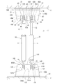
転倒防止装置1は、図1及び図2に示すように複数のダンパ10、物品側のベース部30A、天井側のベース部30B,30Cを備える。
図1、図2等で示す転倒防止装置1において、2つのダンパ10は同一の構造となっている。ダンパ10は、シリンダ(cylinder)11、図示しないロッドガイド、図示しないピストン(piston)、ロッド(rod)13、及び両端に設けられた2個のジョイント(joint)部15を有している。シリンダ11は有底筒状である。ロッドガイドはシリンダ11の開口部を封鎖している。ピストンはシリンダ11内に摺動自在に挿入されている。ロッド13は基端部がピストンに連結されている。また、ロッド13はロッドガイドを挿通して先端側がシリンダ11の外部へ突出している。シリンダ11は作動油及び圧縮ガス(gas)を封入している。各ジョイント部15は、図1~図3に示すように、平板状の金具を折り曲げて形成されている。また、各ジョイント部15はシリンダ11の底部とロッド13の先端部に接続されている。各ジョイント部15はダンパ10の軸線に直交する方向に貫通した貫通孔15Aが形成されている。
2つのダンパ10はいずれも、伸長動作時に発生する減衰力が収縮動作時に発生する減衰力よりも小さい圧効きダンパである。ここで、ダンパ10の伸長動作とは、シリンダ11からロッド13の突出長さ及びダンパ10の長さが長くなっていく動作を意味する。また、ダンパ10の収縮動作とは、シリンダ11からロッド13の突出長さ及びダンパ10の長さが短くなっていく動作を意味する。また、ダンパ10はシリンダ11に封入した圧縮ガスの膨張力が伸長方向に働いている。
ダンパ10の減衰力が発生するメカニズム(mechanism)は、周知の構造であるため、図示を省略して説明する。シリンダ11は、内部がピストンによって、ロッド13の基端部が収納されているロッド側圧力室と、反ロッド側圧力室とに仕切られている。ピストンは両圧力室間を連通させる絞り弁であるオリフィス(orifice)が形成されている。オリフィスは、ダンパ10の伸縮動作に伴うロッド側圧力室と反ロッド側圧力室との間の作動油の流れに抵抗を付与して減衰力を発生する減衰力発生部として機能する。また、ピストンは逆止弁を介して両圧力室間を連通する連通路が形成されている。逆止弁は、ロッド側圧力室から反ロッド側圧力室への作動油の流れを許容し、その逆の流れを阻止する。このため、ダンパ10は、伸長動作時、ロッド側圧力室から反ロッド側圧力室への作動油の流路経路が、オリフィスと連通路の経路になる。一方、ダンパ10は、収縮動作時、反ロッド側圧力室からロッド側圧力室への作動油の流路経路がオリフィスのみとなる。このため、ダンパ10は伸長動作時に発生する減衰力が収縮動作時に発生する減衰力よりも小さくなる。
家具Fの上面A1に載置される物品側のベース部30Aは、2つのダンパ10における一方側の端部がいずれも連結される。2つのダンパ10における各シリンダ11の底部にはジョイント部15が接続されており、これらジョイント部15が物品側のベース部30Aに対し回動可能に連結される。
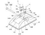
物品側のベース部30Aは、ベース部本体131、回動軸部材であるボルト(bolt)145及びナット(nut)147、ブッシュ(bush)135、及び滑り止め部137を有している。
家具Fの上面に当接して載置された状態で物品側のベース部30Aを上方から見た平面視において、ベース部本体131は長方形状の外形である。以下、この平面視におけるベース部本体131の外形において長辺が延びている方向を「長辺方向」と言い、短辺が延びている方向を「短辺方向」と言う。また、家具Fの上面に当接して載置された状態で物品側のベース部30Aを短辺方向に見た側面視において、ベース部本体131は、下端縁が家具Fの上面に平行に直線状に伸びており、上端縁が下端縁の両側から上方に膨らんだ円弧状の外形である(図1参照)。また、家具Fの上面に当接して載置された状態で物品側のベース部30Aを長辺方向に見た側面視において、ベース部本体131は下端縁よりも上端縁が短い略台形状の外形である(図2及び図3参照)。
物品側のベース部30Aにおいて、ベース部本体131は上面に長辺方向(図1における左右方向であり、図2及び図3における奥行き方向)に伸びた溝部141が形成されている。溝部141は、底面141Aが物品への接触面(滑り止め部137の下面)と略平行に構成され、内壁面141Bが底面141Aの両側において底面141Aに対し略垂直に立ち上がっている。溝部141は、後述する凸部143,144,146が形成されている部分を除き、幅が一定である。
溝部141は、図4に示すように、長辺方向の中央部に溝部141の底面141A及び両内壁面141B,141Bから突出した一対の凸部143,146が形成されている。凸部143,146の間には、底面141Aから上方に突出した凸部144が形成されている。これら凸部143,144,146は、各凸部間にダンパ10のジョイント部15及び後述するブッシュ135が嵌まり込む空間が形成されている。この空間は溝部141に連通している。凸部143,144の内壁面同士の間隔(空間の短辺方向の長さ)は後述するブッシュ135の長さよりも僅かに大きい。同様に、凸部144,146の内壁面同士の間隔(空間の短辺方向の長さ)はブッシュ135の長さよりも僅かに大きい。凸部143,144,146の各々には、後述するボルト145の軸部145Bが挿通される挿通孔143B,144B,146Bが短辺方向に貫通した形で形成されている。
物品側のベース部30Aにおいて、ベース部本体131は、長辺方向の中央部であって、溝部141の両側に窪み部142が形成されている。これら窪み部142は上方向と短辺方向の外方向に開口している。これら窪み部142は凸部143,146を貫通した各挿通孔143B,146Bが側面にそれぞれ開口している。更に、中央の凸部144にも、挿通孔144Bが形成されており、これら凸部143,144,146の挿通孔143B,144B,146Bに、ボルト145を挿し込むことができるようになっている。一対の窪み部142には、ボルト145の頭部145Aと、このボルト145にねじ込まれるナット147の夫々が配置される。これら窪み部142は、ボルト145の頭部145Aとナット147に対し上方から工具を嵌合させることができるように、長辺方向において上方に広がるように形成されている。ボルト145は、ベース部本体131の一方側から凸部143,144,146の各挿通孔143B,144B,146Bに挿入され、ベース部本体131の他方側では、このボルト145の軸部145Bにナット147がねじ込まれる。ボルト145の中心軸は、2つのダンパ10の回動軸になる。つまり、2つのダンパ10は、同一の回動軸を中心として回動する。
ベース部本体131の内部は空洞状に構成され、内部に短辺方向に平行に伸びた複数条のリブ(rib)と、長辺方向に平行に伸びた複数のリブとが交差して形成されている。
ブッシュ135は、図3に示すように、略円筒状である。ブッシュ135は弾性体である。ブッシュ135の長さはベース部本体131に設けられた凸部143,144,146の内壁面同士の間隔によりも僅かに小さい。ブッシュ135は中央部の外周面を一周した凹部135Aが形成されている。この凹部135Aの外径がダンパ10のジョイント部15に形成された貫通孔15Aの内径に略等しい。ブッシュ135は凹部135Aの両端から立ち上がった部分の外径がダンパ10のジョイント部15に形成された貫通孔15Aの内径よりも大きい。また、ブッシュ135は両端部の外周面135Bが外方向に縮径している。このため、ブッシュ135はダンパ10のジョイント部15に形成された貫通孔15Aに弾性変形させながら挿入される。そして、ブッシュ135は、貫通孔15Aに凹部135Aが嵌まり込んで、ダンパ10のジョイント部15に取り付けられる。
ブッシュ135は中央部の内径がボルト145の軸部145Bの外径よりも僅かに大きい。また、ブッシュ135は両端部の内周面135Cが外方向に拡径している。このため、このブッシュ135はボルト145の軸部145B周りに回動自在である。また、このブッシュ135は、拡径した両端部の内周面135Cがボルト145の軸部145Bの外周面に当接する範囲で、ボルト145の軸部145Bに対して傾くことができる。つまり、ブッシュ135をジョイント部15に取り付けたダンパ10は、ボルト145の軸部145B周りに回動自在であり、回動方向と交差する方向に揺動自在である。具体的には、寸法上の余裕と内周面135Cの拡径によって揺動する。さらに、ブッシュ135が弾性変形することによって、ダンパ10は回動方向と交差する方向に、より大きく揺動することができる。
滑り止め部137は、図1~図4に示すように、ベース部本体131の外形に僅かに大きい相似形(長方形状)の外形である。滑り止め部137はゴム(rubber)製である。また、滑り止め部137は、家具Fの上面に当接して載置された状態の物品側のベース部30Aにおいて、ベース部本体131の下端開口に嵌合される。また、滑り止め部137は略平板である。滑り止め部137は、家具Fの上面A1に当接する面が平坦であり、その反対側を向いた面(ベース部本体131に対向する面)は、ベース部本体131の外周壁及び内部のリブに合わせた嵌合溝が形成されている。滑り止め部137はその弾性力によってベース部本体31に着脱自在に取り付けられる。
天井側のベース部30B,30Cは、同一の構造となっている。よって、以下では、天井側のベース部30Bについて、詳細に説明し、天井側のベース部30Cについては、天井側のベース部30Bと同一の構造であるとして、詳細な説明は省略する。
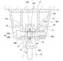
図2のように、天井側のベース部30Bは、ベース部本体31、ボルト45及びナット47、ブッシュ35、及び滑り止め部37を有している。
天井側のベース部30Bのベース部本体31は、天井への接触面(滑り止め部37の接触面)とは反対面側にその接触面と平行方向且つボルト45の中心軸と直交する方向に伸びた溝部41が形成されている。溝部41は、天井への接触面(滑り止め部37の接触面)と平行に底面41Aが設けられ、内壁面41Bが底面41Aの両側に略垂直に設けられている。溝部41は、一対の凸部43,43が形成されている部分を除き、幅が一定に形成されている。
溝部41は、長辺方向の中央部に溝部41の底面41A及び両内壁面41B,41Bから突出した一対の凸部43,43が形成されている。これら凸部43,43は、図2及び図5に示すように、その間にダンパ10のジョイント部15及び後述するブッシュ35が嵌まり込む空間が形成され、この空間は溝部41に連通する。一対の凸部43,43の内壁面43A,43A同士の間隔(空間の短辺方向の長さ)は後述するブッシュ35の長さよりも僅かに大きい。また、一対の凸部43,43はボルト45の軸部45Bが挿通する挿通孔43Bが短辺方向に貫通している。
天井側のベース部30Bにおいて、ベース部本体31は、ベース部本体31の長手方向中央部且つ溝部41の両側に窪み部42が形成されている。この窪み部42は凸部43を貫通した挿通孔43Bが側面に開口している。この窪み部42は後述するボルト45の頭部45Aと、このボルト45にねじ込まれたナット47の夫々が配置される。この窪み部42は、ボルト45の頭部45Aとナット47に工具を嵌合させることができるように、広がった形状をなす。ボルト45の中心軸は、各天井側のベース部30B,30Cにおけるダンパ10の回動軸になる。
図5のように、ブッシュ35は、略円筒状であり、弾性体となっている。ブッシュ35の長さはベース部本体31に設けられた一対の凸部43,43の内壁面43A,43A同士の間隔よりも僅かに小さい。ブッシュ35は中央部の外周面を一周した凹部35Aが形成されている。この凹部35Aの外径がダンパ10のジョイント部15に形成された貫通孔15Aの内径に略等しい。ブッシュ35は凹部35Aの両端から立ち上がった部分の外径がダンパ10のジョイント部15に形成された貫通孔15Aの内径よりも大きい。
ブッシュ35は中央部の内径がボルト45の軸部45Bの外径よりも僅かに大きい。また、ブッシュ35は両端部の内周面35Cが外方向に拡径している。このため、このブッシュ35はボルト45の軸部45B周りに回動自在である。また、このブッシュ35は、拡径した両端部の内周面35Cがボルト45の軸部45Bの外周面に当接する範囲で、ボルト45の軸部45Bに対して傾くことができる。つまり、ブッシュ35をジョイント部15に取り付けたダンパ10は、ボルト45の軸部45B周りに回動自在であり、回動方向と交差する方向に揺動自在である。具体的には、寸法上の余裕と内周面35Cの拡径によって揺動する。さらに、ブッシュ35が弾性変形することによって、ダンパ10は回動方向に交差する方向に、より大きく揺動することができる。
滑り止め部37は、ベース部本体31の外形よりも僅かに大きい相似形(長方形状)の外形である。滑り止め部37はゴム製であり、略平板である。滑り止め部37はその弾性力によってベース部本体31に着脱自在に取り付けられる。
このように構成された転倒防止装置1は、例えば、図1、図6のように、床面Fr(設置面)上に設置された家具F(物品)の上面A1と天井Cの間に取り付けられる。転倒防止装置1は、2つのダンパ10の一方側の端部がいずれも物品側のベース部30Aに連結され、物品側のベース部30Aが両ダンパ10のベースとして兼用される。一方、2つのダンパ10の他方側の端部には、2つの天井側のベース部30B,30Cがそれぞれ個別に連結される。
図1、図6の取付状態では、転倒防止装置1が家具F(物品)の上面A1と天井Cとの間に取り付けられた状態で、物品側のベース部30Aの中央部を通る鉛直方向の仮想線L1の両側にそれぞれ天井側のベース部30B,30Cが配置される。仮想線L1の一方側に配置されるダンパ10(ベース部30Bに連結されるダンパ10)は、ダンパ10の中心軸と鉛直方向とのなす角度がθとなる傾きで配置されている。そして、仮想線L1の他方側に配置されるダンパ10(ベース部30Cに連結されるダンパ10)も、ダンパ10の中心軸と鉛直方向とのなす角度がθとなる傾きで配置されている。つまり、両ダンパ10は、鉛直方向に対する傾きは同じであり、一方のダンパ10は、前側に倒れた形(上方側となるにつれて前位置となる傾斜状態)で配置される。他方のダンパ10は、後ろ側に倒れた形(上方側となるにつれて後ろ位置となる傾斜状態)で配置される。
また、図6のように、家具F(物品)の底部B2は、家具Fの高さ方向と直交する所定方向(上述した左右方向)が長手方向である長手状(具体的には、底面視長方形状)となっている。このため、家具Fを床面Frに載置した場合、高さ方向及び長手方向と直交する短手方向(上述した前後方向)に倒れやすい載置状態となる。これに対し、転倒防止装置1は、家具Fの前後方向(高さ方向及び長手方向と直交する直交方向)において、底部B2の中心位置P1と、物品側のベース部30Aの配置範囲AR1とが重なっている。つまり、物品側のベース部30Aの直下に中心位置P1が位置する。
図7には、物品側のベース部30A及び家具Fを平面視した場合の、物品側のベース部30Aと底部B2との位置関係を簡略的に示し、物品側のベース部30Aの外縁形状と、底部B2の外縁形状とを簡略的に示している。底部B2の外縁については一点鎖線にて位置を仮想的に示す。図7のように、物品側のベース部30Aの直下に、底部B2の前後方向の中心位置P1が位置し、より具体的には、ボルト145の中心軸の位置(即ち、ダンパ10の回動中心)の直下の位置が、底部B2の前後方向の中心位置P1となっている。
このように転倒防止装置1が取り付けられた家具Fが、地震の揺れ等によって、前後方向に揺動して前方向に傾いた場合、家具Fの上面A1に面接触した物品側のベース部30Aから斜め前側に延びた圧効きダンパ10が収縮動作し、減衰力を発揮する。このため、家具Fは、ダンパ10によって前方向へ傾く力が減衰され、前方向への傾き量が抑制される。また、前後方向に揺動して後方向に傾いた際、家具Fの上面A1に面接触した物品側のベース部30Aから斜め後ろ側に延びた圧効きダンパ10が収縮動作し、減衰力を発揮する。このため、家具Fは、ダンパ10によって後方向へ傾く力が減衰され、後ろ方向への傾き量が抑制される。
このように、この転倒防止装置1は、地震の揺れ等によって、圧効きダンパ10の軸線が延びている方向、すなわち家具Fの前後方向に家具Fが傾くと、床面Fr上に設置された家具Fの上面A1と天井Cとの間に取り付けられた圧効きダンパ10が収縮動作する。これにより、減衰力が発生し、家具Fの傾く力を減衰するため、家具Fの傾き量が抑制されて家具Fの転倒を防止することができる。また、この転倒防止装置1は床面Frから鉛直に立ち上がった壁面の近くに設置されていない家具Fに対しても取り付けることができ、家具Fの転倒を防止することができる。しかも、家具Fの天板のピッチ(上面部の前後方向の幅)が狭くても、十分な角度の傾斜をもって複数のダンパ10を設置することができる。
以上の説明のように、転倒防止装置1は、複数のダンパ10を有し、複数のダンパ10の一方側端部がいずれも物品側のベース部30Aに連結されている。この転倒防止装置1を家具F(物品)の上面A1と天井Cの間に取り付ける場合、家具F側では各ダンパ10に対して個別にベース部を設けずに済み、共通化された物品側のベース部30Aで兼用することができる。このため、ダンパの数が増えても、ベース部の設置に必要な物品上面の面積を増大させすぎることなく抑えることができる。しかも、複数のダンパ10を物品側のベース部30Aで連結させて一体的に管理することができ、ベース部を物品上で位置決めして載置する場合、ベース部を個別に載置して個別に位置決めするような手間を省くことができる。また、ベース部の個数を減らすことができるため、組立工数及びコスト(cost)の削減となる。
したがって、家具F(物品)の上面A1と天井Cの間に複数のダンパ10を取り付けることができ、且つ作業工数の増大及び設置スペースの増大を抑えることができる。
転倒防止装置1は、複数のダンパ10の他方側端部(物品側のベース部30A側とは反対側の端部)に、複数の天井側のベース部30B,30Cがそれぞれ個別に連結されている。この構成によれば、物品側については、ベース部を共通化することで作業工数の増大及び設置スペースの増大を抑えることができる。天井側については、ダンパ毎に個別にベース部を設けることで、設置する上での自由度を大きくすることができる。特に、物品の上面サイズや形状等によって制約を受ける物品側のベース部については、共通化を図ることで物品による制約に適応しやすい構成とすることができる。一方、物品側と比較してスペース的に余裕が生じやすい天井側については、ダンパ毎にベース部の位置を設定できるようにして、細かな調整を行えるようにすることができる。
転倒防止装置1は、家具F(物品)の上面A1と天井Cの間に取り付けられた状態で、物品側のベース部30Aの中央部を通る鉛直方向の仮想線L1の両側にそれぞれ天井側のベース部30B,30Cが配置される。本構成は、物品側のベース部30Aの長辺方向の中央位置及び短辺方向の中央位置が中央部であり、具体的には、仮想線L1は、ボルト145の中心軸と交差する鉛直方向の仮想的な直線となっている。
この構成では、物品側のベース部30Aを基準として仮想線L1の一方側に傾倒した形で一方のダンパ10が取り付けられ、他方側に傾倒した形で他方のダンパ10が取り付けられることになる。この構成によれば、家具Fが一方側へ傾いた場合でも、他方側へ傾いた場合でも、家具Fを傾かせる力を効果的に減衰させ、家具Fの傾きを抑制することができる。家具Fが他の物品の場合でも同様の効果が生じる。
特に、このような効果は、壁面に隣接して設置されていない、いわゆる「島置き状態」の家具に転倒防止装置1を適用した場合に顕著となる。「島置き状態」の家具は、壁面による支えが無いため転倒方向(転倒しやすい方向)の一方側にも他方側にも傾く可能性があり、従来の転倒防止装置では適用しにくいという問題があった。しかし、本構成の転倒防止装置1を用いれば、一方側へ傾いた場合でも、他方側へ傾いた場合でも減衰力が生じるように設置することができる。よって、このような「島置き状態」の家具に効果的に利用することができる。
転倒防止装置1は、仮想線L1の一方側に配置されるダンパ10の鉛直方向に対する傾きと、仮想線L1の他方側に配置されるダンパ10の鉛直方向に対する傾きとが同一となっている。この構成によれば、家具Fの一方側への傾きについても、他方側への傾きについてもバランス良く減衰させることができる。
家具Fの底部B2は、家具Fの高さ方向と直交する所定方向(左右方向)が長手方向である長手状となっている。転倒防止装置1は、家具Fの前後方向(高さ方向及び底部B2の長手方向と直交する直交方向)において、底部B2の中心位置と、物品側のベース部30Aの配置範囲とが重なっている。つまり、物品側のベース部30Aの直下に、底部B2の前後方向中心位置がある。家具Fは、底部B2の長手方向(左右方向)と直交する方向(前後方向)に傾きやすく、その直交方向における底部B2の両端部(即ち、前端部及び後端部)には傾きに起因する浮き上がりが生じやすくなる。このため、物品側のベース部30Aの直下に物品底部の中心位置(家具Fにおける前後方向の中心位置)が配置される構成とすれば、物品底部の前端部又は後端部に浮き上がりが偏ることを防ぐことができる。よって、長手方向と直交する方向の両側の傾きをバランスよく防ぐことができる。
<実施形態2>
次に、実施形態2の転倒防止装置について図8、図9などを参照して説明する。
実施形態2の転倒防止装置201は、実施形態1で複数設けられる天井側のベース部30B、30C(図1等)を一体化して共通の天井側のベース部230Bとした点が実施形態1と異なり、この点以外は実施形態1と同一である。よって、実施形態1の転倒防止装置1と同一の部分については、実施形態1の転倒防止装置1と同一の符号を付し、詳細な説明は省略する。
次に、実施形態2の転倒防止装置について図8、図9などを参照して説明する。
実施形態2の転倒防止装置201は、実施形態1で複数設けられる天井側のベース部30B、30C(図1等)を一体化して共通の天井側のベース部230Bとした点が実施形態1と異なり、この点以外は実施形態1と同一である。よって、実施形態1の転倒防止装置1と同一の部分については、実施形態1の転倒防止装置1と同一の符号を付し、詳細な説明は省略する。
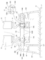
図8、図9のように、本構成の転倒防止装置201は、2つのダンパ10の他方側の端部(物品側のベース部30Aとは反対側の端部)がいずれも、共通の天井側のベース部230Bの異なる位置にそれぞれ連結されている。
共通の天井側のベース部230Bにおけるベース部本体231と2つのダンパ10との接続構造は、実施形態1における2つのベース部本体31と2つのダンパ10との接続構造と同一である。図8、図9で示す共通の天井側のベース部230Bには、実施形態1の天井側のベース部30B(図2、図5等)に形成された2つの凸部43及び2つの挿通孔43Bと同一の位置関係で2つの凸部43及び2つの挿通孔43Bが設けられている。また、天井側のベース部230Bには、実施形態1の天井側のベース部30Cに形成された2つの凸部43及び2つの挿通孔43B(図2、図5等)と同一の位置関係で2つの凸部43及び2つの挿通孔43Bが設けられている。そして、図8、図9で示す天井側のベース部230Bでは、ボルト45及びナット47を組み合わせた2つの組が、実施形態1におけるボルト45及びナット47を組み合わせた2つの組と同様の位置関係で設けられている。このような構造により、2つのボルト45の軸部45Bが平行に位置決めされており、これら軸部45Bの各中心が、各ダンパ10の回動軸となっている。
図2、図5等で示す天井側のベース部30B,30Cを、図8、図9で示す共通の天井側のベース部230Bに変更する場合、ベース部本体231の幅が若干大きくなり、両ダンパ10に対する両連結部分が幅方向両側にずれた配置となる。この点については、例えば、窪み部42(図5)に相当する部分を、幅方向に深く構成して対応すればよい。例えば、図9において、手前側に配置されるボルト45及びナット47の組を収容する1対の窪み部(図5の窪み部42と同様の部分)のうち、ナット47を収容する窪み部については、幅方向(ボルト45の軸方向)に深く構成すればよい。また、図9において、奥側に配置されるボルト45及びナット47の組を収容する1対の窪み部(図5の窪み部42と同様の部分)のうち、ボルト45を収容する窪み部については、幅方向(ボルト45の軸方向)に深く構成すればよい。このようにすれば、一対のボルト45及びナット47を、図8、図9のような平行の関係で2組保持することができ、それらのボルト45に対し、2つのダンパ10のそれぞれのジョイント部15を回動可能に取り付けることができる。滑り止め部237は、ゴム製且つ略平板であり、ベース部本体231よりも大きい相似形(長方形状)の外形である。滑り止め部237は、その弾性力によってベース部本体231に着脱自在に取り付けられる。
なお、図8、図9では、共通の天井側のベース部230Bでの保持構造を例示した。しかし、あくまで例示であり、天井側のベース部230Bでの保持構造は、2つのダンパ10の他方側の端部をいずれも回動可能に保持することができ、それら端部の回動軸(回動の中心軸)が平行且つ一定間隔で定められる構成であればよい。
図8、図9で示す転倒防止装置201では、2つのダンパ10の一方側の端部が、物品側のベース部30Aにおいて共通の軸部材(ボルト145)により回動可能に保持され、2つのダンパ10は、共通の回動軸を中心として回動可能とされている。そして、2つのダンパ10の他方側の端部は、共通の天井側のベース部230Bにおいて、別々の軸部材(2つのボルト45)により回動可能に保持され、それぞれのダンパ10が別々の回動軸(平行な回動軸)を中心として回動可能とされている。
図8で示す転倒防止装置201は、家具Fの上面A1と天井Cとの間に取り付けられた状態で、物品側のベース部30Aの中央部を通る鉛直方向の仮想線L1(実施形態1の仮想線L1と同様の仮想線)の両側に、各ダンパ10の各他方側端部がそれぞれ配置されている。一方のダンパ10は、仮想線L1の一方側に傾き、他方のダンパ10は、仮想線L1の他方側に傾いた配置となっている。そして、仮想線L1の一方側に配置されるダンパ10の鉛直方向に対する傾きθと、仮想線L1の他方側に配置されるダンパ10の鉛直方向に対する傾きθとが同一となっている。また、この例でも、実施形態1(図6、図7)と同様、家具Fの底部B2は、家具Fの高さ方向と直交する所定方向が長手方向である長手状とすることができる。そして、実施形態1と同様、家具Fの高さ方向及び長手方向と直交する直交方向において、底部Bの中心位置と、物品側のベース部30Aの配置範囲とが重なっていてもよい。
本構成の転倒防止装置201によれば、物品側だけでなく天井側についてもベース部の共通化により部品数の削減を図ることができ、コストの削減を図りやすくなる。また、天井側に設置すべき部品数が減るため、作業工数の増大を抑えることができる。
また、本構成の転倒防止装置201は、両ダンパ10の角度が予め定められた角度で固定化される。このため、両ダンパ10の角度変更が不要な用途、角度変更をしなくても良い用途、角度変更が望ましくない用途などに効果的に適用できる。
本発明は上記記述及び図面によって説明した各実施形態に限定されるものではなく、例えば次のような実施形態も本発明の技術的範囲に含まれる。
(1)実施形態1、2では、転倒防止装置を家具に対して取り付けたが、地震等の揺れによって転倒するおそれのある、書棚、冷蔵庫等の物品に対して取り付けてもよい。
(2)実施形態1、2では、前面部F1及び裏面部F2に物品を対向させない形で床面Fr上に載置された家具に対して転倒防止装置1を取り付けたが、裏面部F2を壁面Wに隣接させた形で床面上に載置された家具等に対して取り付けてもよい。
(3)実施形態1、2では、転倒防止装置の正面、側面などを便宜的に示したが、これらは家具の正面、側面などとは異なる概念である。つまり、家具の正面と転倒防止装置の正面とは必ずしも一致する必要はなく、転倒防止装置は、家具の向きに対して様々な向きで取り付け得る。
(4)実施形態1、2では、2つのダンパが設けられた構成を例示したが、3以上のダンパが設けられていてもよい。この場合、それらダンパに接続される天井側のベース部は、それぞれが独立して設けられていてもよく、全部又はいくつかが一体化されていてもよい。
(5)実施形態1、2では、各部がダンパの両端部の夫々を回動軸周りに回動自在、かつ回動方向に交差する方向に揺動自在に連結していたが、回動自在に連結しなくてもよいし、揺動自在に連結しなくてもよい。
(6)実施形態1、2では、複数のダンパ10をいずれも圧効きダンパとしたが、複数のダンパをいずれも、伸長動作時及び収縮動作時に発生する減衰力が等しい両効きダンパとしてもよい。或いは、複数のダンパをいずれも、伸長動作時に発生する減衰力が収縮動作時に発生する減衰力よりも大きい伸効きダンパであってもよい。或いは、これら複数種類のダンパを混在させてもよい。
(7)実施形態1、2では、シリンダ内に作動油及び圧縮ガスを封入したダンパを利用したが、収縮動作時に所定の減衰力を発生させるものであれば、他の液体を封入した液体圧ダンパであっても、他の形式のダンパであってもよい。
(8)実施形態1、2では、シリンダ内に圧縮ガスを封入して伸張方向に圧縮ガスの膨張力が働くようにしたが、他の方式で伸張方向に働く力を発生させてもよい。
(1)実施形態1、2では、転倒防止装置を家具に対して取り付けたが、地震等の揺れによって転倒するおそれのある、書棚、冷蔵庫等の物品に対して取り付けてもよい。
(2)実施形態1、2では、前面部F1及び裏面部F2に物品を対向させない形で床面Fr上に載置された家具に対して転倒防止装置1を取り付けたが、裏面部F2を壁面Wに隣接させた形で床面上に載置された家具等に対して取り付けてもよい。
(3)実施形態1、2では、転倒防止装置の正面、側面などを便宜的に示したが、これらは家具の正面、側面などとは異なる概念である。つまり、家具の正面と転倒防止装置の正面とは必ずしも一致する必要はなく、転倒防止装置は、家具の向きに対して様々な向きで取り付け得る。
(4)実施形態1、2では、2つのダンパが設けられた構成を例示したが、3以上のダンパが設けられていてもよい。この場合、それらダンパに接続される天井側のベース部は、それぞれが独立して設けられていてもよく、全部又はいくつかが一体化されていてもよい。
(5)実施形態1、2では、各部がダンパの両端部の夫々を回動軸周りに回動自在、かつ回動方向に交差する方向に揺動自在に連結していたが、回動自在に連結しなくてもよいし、揺動自在に連結しなくてもよい。
(6)実施形態1、2では、複数のダンパ10をいずれも圧効きダンパとしたが、複数のダンパをいずれも、伸長動作時及び収縮動作時に発生する減衰力が等しい両効きダンパとしてもよい。或いは、複数のダンパをいずれも、伸長動作時に発生する減衰力が収縮動作時に発生する減衰力よりも大きい伸効きダンパであってもよい。或いは、これら複数種類のダンパを混在させてもよい。
(7)実施形態1、2では、シリンダ内に作動油及び圧縮ガスを封入したダンパを利用したが、収縮動作時に所定の減衰力を発生させるものであれば、他の液体を封入した液体圧ダンパであっても、他の形式のダンパであってもよい。
(8)実施形態1、2では、シリンダ内に圧縮ガスを封入して伸張方向に圧縮ガスの膨張力が働くようにしたが、他の方式で伸張方向に働く力を発生させてもよい。
1,201…転倒防止装置、10…ダンパ、30A…物品側のベース部、30B,30C…天井側のベース部、230B…天井側のベース部(共通の天井側のベース部)、B2…底部、C…天井、F…家具(物品)、Fr…床面(設置面)、L1…仮想線
Claims (8)
- 設置面上に設置された物品の上面と天井との間に取り付けられる複数のダンパと、
前記物品の上面に載置され、複数の前記ダンパの一方側の端部がいずれも連結される物品側のベース部と、
複数の前記ダンパの他方側の端部に連結される1又は複数の天井側のベース部と、
を備えていることを特徴とする転倒防止装置。 - 複数の前記ダンパの前記他方側の端部には、複数の前記天井側のベース部がそれぞれ個別に連結されていることを特徴とする請求項1に記載の転倒防止装置。
- 複数の前記ダンパのいずれか複数又は全部の前記他方側の端部が、共通の前記天井側のベース部の異なる位置にそれぞれ連結されていることを特徴とする請求項1に記載の転倒防止装置。
- 前記物品の上面と前記天井との間に取り付けられた状態で、前記物品側のベース部の中央部を通る鉛直方向の仮想線の両側にそれぞれ前記天井側のベース部が配置されることを特徴とする請求項1に記載の転倒防止装置。
- 前記仮想線の一方側に配置される前記ダンパの鉛直方向に対する傾きと、前記仮想線の他方側に配置される前記ダンパの鉛直方向に対する傾きとが同一であることを特徴とする請求項4記載の転倒防止装置。
- 前記物品の底部は、前記物品の高さ方向と直交する所定方向が長手方向である長手状であり、
前記物品の高さ方向及び前記長手方向と直交する直交方向において、前記底部の中心位置と、前記物品側のベース部の配置範囲とが重なっていることを特徴とする請求項1に記載の転倒防止装置。 - 前記物品の上面と前記天井との間に取り付けられた状態で、前記物品側のベース部の中央部を通る鉛直方向の仮想線の両側にそれぞれ前記天井側のベース部が配置され、
前記仮想線の一方側に配置される前記ダンパの鉛直方向に対する傾きと、前記仮想線の他方側に配置される前記ダンパの鉛直方向に対する傾きとが同一であり、
前記物品の底部は、前記物品の高さ方向と直交する所定方向が長手方向である長手状であり、
前記物品の高さ方向及び前記長手方向と直交する直交方向において、前記底部の中心位置と、前記物品側のベース部の配置範囲とが重なっていることを特徴とする請求項2に記載の転倒防止装置。 - 前記物品の上面と前記天井との間に取り付けられた状態で、前記物品側のベース部の中央部を通る鉛直方向の仮想線の両側にそれぞれ前記天井側のベース部が配置され、
前記仮想線の一方側に配置される前記ダンパの鉛直方向に対する傾きと、前記仮想線の他方側に配置される前記ダンパの鉛直方向に対する傾きとが同一であり、
前記物品の底部は、前記物品の高さ方向と直交する所定方向が長手方向である長手状であり、
前記物品の高さ方向及び前記長手方向と直交する直交方向において、前記底部の中心位置と、前記物品側のベース部の配置範囲とが重なっていることを特徴とする請求項3に記載の転倒防止装置。
Priority Applications (2)
| Application Number | Priority Date | Filing Date | Title |
|---|---|---|---|
| CN201680074938.5A CN108471878A (zh) | 2015-12-25 | 2016-12-22 | 翻倒防止装置 |
| US16/064,755 US20190008277A1 (en) | 2015-12-25 | 2016-12-22 | Overturn preventing device |
Applications Claiming Priority (2)
| Application Number | Priority Date | Filing Date | Title |
|---|---|---|---|
| JP2015-254392 | 2015-12-25 | ||
| JP2015254392A JP6678025B2 (ja) | 2015-12-25 | 2015-12-25 | 転倒防止装置 |
Publications (1)
| Publication Number | Publication Date |
|---|---|
| WO2017111063A1 true WO2017111063A1 (ja) | 2017-06-29 |
Family
ID=59090486
Family Applications (1)
| Application Number | Title | Priority Date | Filing Date |
|---|---|---|---|
| PCT/JP2016/088457 Ceased WO2017111063A1 (ja) | 2015-12-25 | 2016-12-22 | 転倒防止装置 |
Country Status (5)
| Country | Link |
|---|---|
| US (1) | US20190008277A1 (ja) |
| JP (1) | JP6678025B2 (ja) |
| CN (1) | CN108471878A (ja) |
| TW (1) | TW201729729A (ja) |
| WO (1) | WO2017111063A1 (ja) |
Families Citing this family (1)
| Publication number | Priority date | Publication date | Assignee | Title |
|---|---|---|---|---|
| US20250261756A1 (en) * | 2024-02-19 | 2025-08-21 | Mirza Faizan | Stabilizer system for controlling tipping of furniture |
Citations (3)
| Publication number | Priority date | Publication date | Assignee | Title |
|---|---|---|---|---|
| JPS6041906A (ja) * | 1983-08-17 | 1985-03-05 | 松浦 祐 | 家具類の転倒防止装置 |
| JP2004358191A (ja) * | 2003-06-07 | 2004-12-24 | Okuda Seisakusho:Kk | 家具等の転倒防止装置 |
| JP2015006330A (ja) * | 2013-05-29 | 2015-01-15 | カヤバ工業株式会社 | 転倒防止装置 |
Family Cites Families (3)
| Publication number | Priority date | Publication date | Assignee | Title |
|---|---|---|---|---|
| US3577659A (en) * | 1969-08-06 | 1971-05-04 | Singer General Precision | Motion simulator actuator joint |
| KR100894017B1 (ko) * | 2007-12-07 | 2009-04-17 | 위니아만도 주식회사 | 냉장고의 전도 방지장치 |
| JP5864066B1 (ja) * | 2014-08-06 | 2016-02-17 | Kyb株式会社 | 転倒防止装置 |
-
2015
- 2015-12-25 JP JP2015254392A patent/JP6678025B2/ja not_active Expired - Fee Related
-
2016
- 2016-12-22 US US16/064,755 patent/US20190008277A1/en not_active Abandoned
- 2016-12-22 WO PCT/JP2016/088457 patent/WO2017111063A1/ja not_active Ceased
- 2016-12-22 CN CN201680074938.5A patent/CN108471878A/zh not_active Withdrawn
- 2016-12-23 TW TW105142980A patent/TW201729729A/zh unknown
Patent Citations (3)
| Publication number | Priority date | Publication date | Assignee | Title |
|---|---|---|---|---|
| JPS6041906A (ja) * | 1983-08-17 | 1985-03-05 | 松浦 祐 | 家具類の転倒防止装置 |
| JP2004358191A (ja) * | 2003-06-07 | 2004-12-24 | Okuda Seisakusho:Kk | 家具等の転倒防止装置 |
| JP2015006330A (ja) * | 2013-05-29 | 2015-01-15 | カヤバ工業株式会社 | 転倒防止装置 |
Also Published As
| Publication number | Publication date |
|---|---|
| CN108471878A (zh) | 2018-08-31 |
| TW201729729A (zh) | 2017-09-01 |
| JP6678025B2 (ja) | 2020-04-08 |
| US20190008277A1 (en) | 2019-01-10 |
| JP2017113425A (ja) | 2017-06-29 |
Similar Documents
| Publication | Publication Date | Title |
|---|---|---|
| US20190021499A1 (en) | Overturn preventing device | |
| WO2017208520A1 (ja) | 転倒防止装置 | |
| JP5864068B1 (ja) | 転倒防止装置 | |
| WO2017111063A1 (ja) | 転倒防止装置 | |
| JP5864066B1 (ja) | 転倒防止装置 | |
| US20200229601A1 (en) | Overturn preventing device | |
| WO2017043267A1 (ja) | 転倒防止装置 | |
| WO2017141563A1 (ja) | ダンパ及びこのダンパを備えた転倒防止装置 | |
| JP6205445B2 (ja) | 転倒防止装置、及びその取り付け方法 | |
| JP2017172704A (ja) | ダンパ装置、及び転倒防止装置 | |
| KR20180039149A (ko) | 전도 방지 장치 | |
| US20180271284A1 (en) | Overturn preventing device | |
| JP2017169854A (ja) | 連結部材及び転倒防止装置 | |
| JP2017169853A (ja) | 転倒防止装置 | |
| JP6386087B2 (ja) | 制振棚 | |
| WO2018173643A1 (ja) | 転倒防止装置 | |
| KR200358921Y1 (ko) | 건설용 보강구 | |
| KR101667537B1 (ko) | 가변 용량 피스톤 유압모터의 사판 지지용 구면 부시 | |
| KR200358923Y1 (ko) | 내진 건설용 보강구 | |
| JP2017176218A (ja) | 転倒防止装置 | |
| WO2018173642A1 (ja) | 転倒防止装置 | |
| TW201713874A (zh) | 防傾倒裝置 | |
| JP2017225539A (ja) | 転倒防止装置 | |
| JP2016063992A (ja) | 転倒防止装置用取付け具及び転倒防止装置 |
Legal Events
| Date | Code | Title | Description |
|---|---|---|---|
| 121 | Ep: the epo has been informed by wipo that ep was designated in this application |
Ref document number: 16878949 Country of ref document: EP Kind code of ref document: A1 |
|
| NENP | Non-entry into the national phase |
Ref country code: DE |
|
| 122 | Ep: pct application non-entry in european phase |
Ref document number: 16878949 Country of ref document: EP Kind code of ref document: A1 |