WO2017110682A1 - β線ガスモニタ及びβ線を放出する核種を含むガスのモニタリング方法 - Google Patents
β線ガスモニタ及びβ線を放出する核種を含むガスのモニタリング方法 Download PDFInfo
- Publication number
- WO2017110682A1 WO2017110682A1 PCT/JP2016/087576 JP2016087576W WO2017110682A1 WO 2017110682 A1 WO2017110682 A1 WO 2017110682A1 JP 2016087576 W JP2016087576 W JP 2016087576W WO 2017110682 A1 WO2017110682 A1 WO 2017110682A1
- Authority
- WO
- WIPO (PCT)
- Prior art keywords
- partition wall
- ray
- gas
- ratio
- sample
- Prior art date
- Legal status (The legal status is an assumption and is not a legal conclusion. Google has not performed a legal analysis and makes no representation as to the accuracy of the status listed.)
- Ceased
Links
Images



Classifications
-
- G—PHYSICS
- G01—MEASURING; TESTING
- G01T—MEASUREMENT OF NUCLEAR OR X-RADIATION
- G01T1/00—Measuring X-radiation, gamma radiation, corpuscular radiation, or cosmic radiation
- G01T1/16—Measuring radiation intensity
- G01T1/167—Measuring radioactive content of objects, e.g. contamination
-
- G—PHYSICS
- G01—MEASURING; TESTING
- G01T—MEASUREMENT OF NUCLEAR OR X-RADIATION
- G01T7/00—Details of radiation-measuring instruments
- G01T7/02—Collecting means for receiving or storing samples to be investigated and possibly directly transporting the samples to the measuring arrangement; particularly for investigating radioactive fluids
Definitions
- Embodiments of the present invention include a ⁇ -ray gas monitor that detects ⁇ -decaying radionuclides released into the atmosphere at a nuclear power plant or facility and measures radioactivity concentration in the atmosphere, and a nuclide that emits ⁇ -rays
- the present invention relates to a gas monitoring method.
- the radiation detector of the radioactive gas monitor installed in the building of a nuclear power plant or nuclear facility has a high radiation emission rate per decay in order to measure the radionuclide in the gas to be measured with high sensitivity.
- the line is the measurement target.
- a radioactive gas to be measured is usually introduced into a sample space, and beta rays emitted by decay of a radionuclide contained in the gas (for example, Kr-85, Xe-133, etc.) And the radioactivity concentration in the gas is calculated based on the detected value.
- a radionuclide contained in the gas for example, Kr-85, Xe-133, etc.
- JP 2010-78319 A Japanese Patent Laid-Open No. 11-64527 Japanese Utility Model Publication No. 62-88974
- the present invention has been made in view of such circumstances, and a ⁇ -ray gas monitor capable of monitoring a radioactivity concentration under measurement conditions suitable for a gas containing a nuclide that emits ⁇ -rays to be measured. And it aims at providing the monitoring method of the gas containing the nuclide which emits a beta ray.
- a ⁇ -ray gas monitor includes a hollow main body with one open end sealed, and a ⁇ -ray detector that is disposed inside the main body, detects ⁇ -rays, and outputs a detection signal. And movably provided along the inner surface of the main body at a position facing the detection port of the ⁇ -ray detector, set at a partition wall position corresponding to the sample gas to be measured, and separated from the external space A variable partition that forms the sample space together with the inner surface of the main body, a count rate meter that measures a count rate based on the detection signal detected from the sample gas introduced into the sample space, and the measured A radioactivity concentration calculation unit for obtaining the radioactivity concentration of the sample gas based on the count rate and the volume of the sample space.
- a method for monitoring a gas containing a nuclide that emits ⁇ -rays includes a hollow main body whose one open end is sealed, and disposed inside the main body to detect ⁇ -rays, A ⁇ -ray detector for outputting a detection signal, and a partition wall position corresponding to the sample gas to be measured, provided to be movable along the inner surface of the main body at a position facing the detection port of the ⁇ -ray detector.
- the count rate is set based on the detection signal detected from the sample gas introduced into the sample space using a variable partition that is formed with the inner surface of the main body to form a sample space separated from the external space. And measuring the radioactivity concentration of the sample gas based on the measured count rate and the volume of the sample space.
- a ⁇ -ray gas monitor capable of monitoring a radioactivity concentration under a measurement condition suitable for a gas containing a nuclide that emits ⁇ -rays to be measured and a nuclide that emits ⁇ -rays are included.
- a gas monitoring method is provided.
- the lineblock diagram of the beta ray gas monitor concerning a 1st embodiment (A) is an enlarged view showing the configuration of the sampler section and the partition wall drive section in the first embodiment, and (B) is a II cross-sectional view.
- the simulation calculation result of the detection efficiency of the beta ray gas monitor concerning this embodiment when the energy of electrons is 0.1, 0.2, 0.3, 0.5, and 1.0 MeV.
- the flowchart which shows the operation
- (A) is a diagram setting position of the variable partition wall showing a state of the sampler in L 1
- (B) is a diagram setting position of the variable partition wall showing a state of the sampler in L 2.
- the flowchart which shows the operation
- the ⁇ -ray gas monitor 10 has a sample space formed by a variable partition wall 13 in which a ⁇ -ray detector 12 is disposed in a main body 11 and is movable along the inner surface of the main body 11. 14, the sampler unit 15 for introducing the sample gas to be measured, the partition wall drive unit 16 for moving the variable partition wall 13 to the set partition wall position, and the count rate based on the ⁇ -ray detection signal s.
- a counting rate meter 17 and a calculator 18 for calculating the radioactive concentration of the sample gas based on the position setting of the variable partition wall 13 and the measured ⁇ ray counting rate are provided.
- the ⁇ -ray gas monitor 10 is variable to an optimum position for ⁇ -ray measurement according to the energy of ⁇ -rays emitted from the sample gas (hereinafter, unless otherwise indicated, means average energy).
- the partition wall 13 is moved to determine the radioactivity concentration of the sample gas.
- FIG. 2A is an enlarged view of the configuration of the sampler unit 15 and the partition wall driving unit 16, and FIG. 2B shows a cross section taken along the line II in FIG.
- the sampler unit 15 includes a main body 11, a ⁇ -ray detector 12, a variable partition wall 13, a rear shielding plug 19, an incident window 20, a gas introduction line 21, and a gas discharge line 22.
- the main body 11 is formed in a hollow shape, and one open end is sealed by a back shielding plug 19.
- the main body 11 is composed of a base 23 made of a material that blocks radiation such as lead and having a cylindrical cavity formed therein, and a protective layer 24 covering the entire surface of the base 23 with a coating material such as iron. Yes.
- the main body 11 can be produced by, for example, hollowing a rectangular parallelepiped lead block into a cylindrical shape and coating the outside and the inside after hollowing with a coating material such as iron.
- the rear shielding plug 19 is formed by protecting the surface of a substrate made of a material that blocks radiation such as lead with a coating material such as iron. By connecting the rear shielding plug 19 to the open end of the main body 11 by welding or the like, one open end of the main body 11 is sealed.
- the ⁇ -ray detector 12 is inserted into the main body 11 with the detection port 25 facing the open side of the main body 11. And it fixes and arrange
- the ⁇ -ray detector 12 is a cylindrical detector configured by connecting a plastic scintillator that emits fluorescence when ⁇ -rays are incident, and a photomultiplier tube that converts the light generated by the scintillator into an electrical signal and outputs it. is there.
- the ⁇ -ray detector 12 is accommodated in a detector case 26 in which a circular detection port 25 is formed.
- the detector case 26 is made of a light shielding material such as aluminum in order to prevent light from entering the detector.
- a plastic scintillator is disposed on the detection port 25 side, and a photomultiplier tube is disposed at a position far from the detection port 25.
- the ⁇ -ray detector 12 is electrically connected to the counting rate meter 17 (FIG. 1), detects ⁇ -rays, and sends a detection signal s generated when the ⁇ -rays are detected to the counting rate meter 17. Output.
- the ⁇ -ray detector 12 is supplied with power from the counting rate meter 17.
- the ⁇ -ray detector 12 is not limited to a combination of a plastic scintillator and a photomultiplier tube, but an ionization chamber or GM tube that detects ⁇ -rays emitted from the gas by converting them into electrical signals. Etc. may be used.
- the incident window 20 is a circular plate made of a material such as iron, and an opening having a larger diameter than the detection port 25 of the ⁇ -ray detector 12 is formed at the center position.
- the incident window 20 is provided in the vicinity of or in contact with the detector case 26 on the detection surface side of the ⁇ -ray detector 12 in order to form the boundary of the sample space 14.
- the variable partition wall 13 is a circular plate material having a diameter smaller than the inner diameter of the main body 11 (diameter capable of sliding on the inner surface of the main body 11). And it arrange
- variable partition wall 13 The surface of the variable partition wall 13 is protected by a partition wall coating layer 28 made of a coating material such as iron on a partition base 27 made of a material that blocks radiation such as lead.
- variable partition wall 13 forms a boundary with the outer space together with the inner surface of the main body 11 and the entrance window 20 to form a sample space 14 separated from the outer space.
- variable partition wall 13 is moved back and forth along the axial direction on the inner surface of the main body 11 by the partition wall drive unit 16, so that the distance from the incident window 20 to the variable partition wall 13 (hereinafter referred to as the partition wall position) and the sample space 14.
- the volume of can be changed.
- the partition wall position may be a distance from the detection port 25 of the ⁇ -ray detector 12 to the variable partition wall 13.
- the gas introduction line 21 is provided with an open valve that is opened when gas is introduced.
- the gas discharge line 22 is provided with an exhaust pump and an open valve that is opened when the gas is discharged.
- the illustration of the exhaust pump and the open valves provided in each line is omitted.
- the exhaust pump is driven to introduce the sample gas into the sample space 14 via the gas introduction line 21 and fill the sample space 14 with the gas, and the sample via the gas discharge line 22.
- the sample gas in the space 14 is discharged.
- the partition wall drive unit 16 moves the variable partition wall 13 to a partition position L set by the computer 18 (FIG. 1), a drive shaft 29 connected to the variable partition wall 13, a stepping motor 30 that drives the drive shaft 29 back and forth. And a motor control unit 31 that transmits a position control signal to the stepping motor 30.
- Rotational motion by the stepping motor 30 is converted into linear motion that moves the variable partition wall 13 forward and backward by the drive shaft 29.
- the variable partition wall 13 may be moved back and forth using a hydraulic or pneumatic cylinder or the like.
- the variable partition wall 13 may be moved to the partition wall position L set by the user by using a configuration in which the motor control unit 31 can accept input by the user.
- the calculator 18 includes an input unit 32, an optimum position information storage unit 33, a partition wall position setting unit 34, a count rate reception unit 35, and a radioactivity concentration calculation unit 36.
- the input unit 32 receives an input of ⁇ -ray energy released from the sample gas from the user.
- the ⁇ -ray energy of the radionuclide assumed to be included in the sample gas is received from the user based on the correspondence relationship with the ⁇ -ray energy generated when each of the radionuclides undergoes ⁇ -ray decay.
- the optimum position information storage unit 33 obtains the optimum position of the partition wall position L in advance by simulation calculation according to each of the set ⁇ -ray energy, and saves it as optimum position information.
- a plurality of ⁇ -ray energies to be set are set in a range of ⁇ -ray energies expected to be emitted.
- the simulation calculation for obtaining the optimum position information is performed using a Monte Carlo calculation code such as PHITS, MCNP, EGS5, etc., with ⁇ -ray energy and partition wall position L as parameters, and a detailed configuration of the sampler unit 15 as a calculation condition. Done.
- a Monte Carlo calculation code such as PHITS, MCNP, EGS5, etc.
- FIG. 3 shows the result of simulation calculation of the detection efficiency of the ⁇ -ray gas monitor 10 when the energy of electrons is 0.1, 0.2, 0.3, 0.5, and 1.0 MeV.
- the history of calculation in each setting is set to 100,000 using PHITS which is a Monte Carlo calculation code.
- the unit of detection efficiency is indicated by cps / (Bq / cm 3 ).
- the diameter of the detection port 25 of the ⁇ -ray detector 12 is set to 200 mm
- the diameter of the opening portion in the incident window 20 is set to 210 mm
- the diameter of the sample space 14 is set to 280 mm. It is supposed to pass on the axis.
- the thickness of the plastic scintillator of the ⁇ -ray detector 12 is 0.25 mm
- the thickness of the protective film is 0.044 mm.
- the detection efficiency is calculated for each ⁇ -ray energy by changing the partition wall position L of the variable partition wall 13.
- FIG. 4 is a graph showing the detection efficiency as a relative value with a detection efficiency of 1 when the setting position of the variable partition wall 13 is 100 cm with respect to the calculation result shown in FIG.
- the detection efficiency is saturated when the position of the variable partition wall 13 is about 10 cm, while the position of the variable partition wall 13 is 10 cm at other energies higher than that.
- the partition wall position L is larger (when the position of the variable partition wall 13 is far from the detection port 25), high detection efficiency is obtained.
- the partition wall position L optimum for measurement differs for each ⁇ -ray energy, and in the case of a gas that emits low energy ⁇ -rays, high detection efficiency can be obtained even when the partition wall position L is small. Furthermore, since the replacement of the gas in the sample space 14 becomes faster, the response time of the detector can also be made faster.
- the partition wall position L 10 cm is the optimum position, while ⁇ -rays with energy higher than 100 keV are emitted.
- the partition position L 20 cm to 45 cm is the optimum position.
- At least one of the detection efficiency and the detection response time of the ⁇ -ray detector 12 becomes higher (exceeds a certain target value) for each of the ⁇ -ray energy. Is obtained and stored in the optimum position information storage unit 33.
- the partition wall position setting unit 34 (FIG. 1) refers to the optimum position information stored in the optimum position information storage unit 33 and determines the optimum position corresponding to the input ⁇ -ray energy to the partition wall position L of the variable partition wall 13. Set to.
- the measurement is started after the variable partition wall 13 is moved to the partition wall position L set by the partition wall position setting unit 34 and the sample gas is introduced into the sample space 14.
- the counting rate meter 17 measures the counting rate based on the ⁇ -ray detection signal s detected by the ⁇ -ray detector 12. The measured count rate is transmitted to the count rate receiving unit 35 of the computer 18.
- the radioactivity concentration calculation unit 36 calculates the radioactivity concentration of the sample gas based on the measured count rate and the volume of the sample space 14.
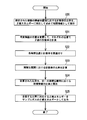
- FIG. 5 shows a flowchart showing an operation procedure of the ⁇ -ray gas monitor 10 according to the first embodiment (see FIG. 1 as appropriate).
- the optimum position information storage unit 33 calculates the optimum partition wall position according to the set ⁇ -ray energy and stores it as optimum position information (S10).
- the input unit 32 receives an input of ⁇ -ray energy released from the sample gas from the user (S11).
- the partition wall position setting unit 34 sets a position corresponding to the ⁇ -ray energy input with reference to the optimum position information as the partition wall position (S12).
- the partition drive unit 16 moves the variable partition 13 to the set partition position (S13). Then, after the sample gas is introduced into the sample space 14, the measurement is started.
- the counting rate meter 17 measures the counting rate based on the ⁇ -ray detection signal s detected by the ⁇ -ray detector 12 (S14).
- the radioactivity concentration calculation unit 36 calculates the radioactivity concentration of the sample gas based on the volume of the sample space 14 corresponding to the partition wall position and the measured count rate (S15).
- the optimum partition position corresponding to the ⁇ -ray energy is obtained by calculation, and the variable partition 13 is moved to the partition position corresponding to the ⁇ -ray energy in the gas to be measured, so that the optimum measurement is performed. Radioactivity concentration can be monitored under conditions.
- FIG. 6 shows a configuration diagram of the ⁇ -ray gas monitor 10 according to the second embodiment.
- portions having the same configuration or function as those of the first embodiment (FIG. 1) are denoted by the same reference numerals, and redundant description is omitted.
- the configuration in which the radioactivity concentration is monitored when the energy of ⁇ rays emitted from the gas to be measured is known has been described.
- a method for estimating the energy of ⁇ rays emitted from the gas when the nuclide component contained in the gas is unknown will be described.
- the ratio of the ⁇ ray count rate when the partition wall position of the variable partition wall 13 is 5 cm and the ⁇ ray count rate when the partition wall position is 20 cm is high when the energy of the ⁇ ray is high. It can be seen that the difference between the low and low cases. That is, the ratio of the ⁇ ray count rate between the partition walls has a different value depending on the energy of the ⁇ ray.
- ⁇ -ray count rates are measured at a plurality of partition wall positions, and ⁇ -ray energy is estimated based on the ratio of ⁇ -ray count rates between the partition wall positions.
- the computer 18 further includes a partition wall position changing unit 37, a data association unit 38, a ratio calculation unit 39, a correlation information storage unit 40, a collation unit 41, and a display unit 42.
- the partition wall position changing unit 37 sets a plurality of partition wall positions.
- the partition wall position changing unit 37 changes the setting to the next partition wall position after the variable partition wall 13 is moved to the set partition wall position and the concentration measurement is completed.
- the data association unit 38 associates the set partition wall positions with the count rate measured at each partition wall position.
- the ratio calculation unit 39 calculates the ratio of the count rate between the partition wall positions after the measurement is completed at the partition wall positions at a plurality of positions.
- the correlation information storage unit 40 (FIG. 6) obtains the ratio of the count rate between the set partition wall positions by simulation calculation in advance according to each of the ⁇ -ray energy and stores it as correlation information.
- the partition wall position set in the simulation calculation is set to the same position as the position set by the partition wall position changing unit 37.
- the simulation calculation for obtaining the correlation information is the same as the above-mentioned optimum position information, and the Monte Carlo calculation such as PHITS, MCNP, EGS5, etc. with the detailed configuration of the sampler unit 15 as the calculation condition using the ⁇ -ray energy and the partition wall position as parameters. Use code.
- the collation unit 41 collates the ratio calculated by the ratio calculation unit 39 with the correlation information ratio between the same partition wall positions, and outputs ⁇ -ray energy corresponding to the matching ratio.
- the display unit 42 displays the output ⁇ -ray energy as an estimated value.
- Figure 7 (A) shows the state of the sampler section 15 when the partition wall position is L 1
- FIG. 7 (B) shows a state of the sampler section 15 in the case where the partition wall position is L 2.
- the partition position changing unit 37 when the partition position is set to L 1 by the partition position changing unit 37, the sample gas is introduced into the sample space A 1 after the movement of the partition is completed. Then, the counting rate based on the ⁇ -ray detection signal s 1 is measured. The data association unit 38 associates the count rate based on the detection signal s 1 corresponding to the partition wall position L 1 .
- the partition wall position by a partition position changing part 37 is changed to L 2
- the sample gas is introduced into the sample space A 2.
- the counting rate based on the ⁇ -ray detection signal s 2 is measured.
- the data association unit 38 associates a count rate based on the detection signal s 2 corresponding to the partition wall position L 2 .
- Ratio calculation unit 39 calculates the ratio of the count rates at the bulkhead position L 1 and the partition position L 2.
- the collation unit 41 collates the ratio calculated by the ratio calculation unit 39 with the ratio of the count rate between the partition wall positions L 1 and L 2 stored for each ⁇ -ray energy by the correlation information storage unit 40. . Then, the collation unit 41 outputs ⁇ -ray energy corresponding to the matching ratio.
- the partition positions set by the partition position changing unit 37 be set to a larger number of positions because the accuracy of collation is increased by acquiring a plurality of ratios.
- FIG. 8 shows a flowchart showing an operation procedure of the ⁇ -ray gas monitor 10 according to the second embodiment (see FIG. 6 as appropriate).
- the correlation information storage unit 40 calculates the ratio of the count rate between the set partition wall positions in advance according to each ⁇ -ray energy and stores it as correlation information (S20).
- the partition wall position changing unit 37 changes the partition wall position of the variable partition wall 13. At this time, the counting rate of ⁇ rays is measured at each changed partition wall position (S21).
- the data association unit 38 associates the set partition positions with the count rates measured at the respective partition positions (S22).
- the ratio calculation unit 39 calculates the ratio of the count rate between the partition wall positions (S23).
- the collation part 41 collates the calculated ratio with the ratio of the correlation information between the same partition positions (S24).
- the collation unit 41 outputs ⁇ -ray energy corresponding to the matching ratio (S25).
- the display unit 42 displays the output ⁇ -ray energy as an estimated value.
- the ⁇ -ray count rate is measured at a plurality of partition wall positions, and the ⁇ -ray count rate ratio between the partition wall positions is obtained, whereby the unknown ⁇ -ray energy can be estimated.
- the correlation information storage unit 40 may calculate the ratio of the counting rate between the set partition wall positions in advance according to each of the continuous energies of different radionuclides and store it as correlation information.
- the collating unit 41 can estimate the radionuclide by collating the ratio calculated by the ratio calculating unit 39.
- the correlation information storage unit 40 calculates in advance the ratio of the counting rate between the partition walls according to each of the set composition ratios of the radionuclides on the assumption that a plurality of types of radionuclides are mixed in the sample gas. And may be stored as correlation information.
- the continuous energy when a plurality of types of radionuclides coexist is calculated by a combination of continuous energies of individual radionuclides.
- the collating unit 41 collates the ratio calculated by the ratio calculating unit 39 with the ratio of the correlation information between the same partition wall positions, and outputs a composition ratio corresponding to the matching ratio.
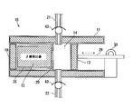
- FIG. 9 shows a configuration diagram of the sampler unit 15 applied to the ⁇ -ray gas monitor 10 according to the third embodiment.
- the whole structure of the beta ray gas monitor 10 in 3rd Embodiment becomes the same as 2nd Embodiment (FIG. 6), description is abbreviate
- the ⁇ -ray gas monitor 10 has a check valve 43 in each of the gas introduction line 21 for introducing the sample gas into the sample space 14 and the gas discharge line 22 for discharging the sample gas from the sample space 14. .
- the ⁇ ray count rate is measured at a plurality of partition wall positions and the ratio of the ⁇ ray count rate between the partition wall positions is obtained as in the second embodiment, acquisition of the count rate can be continuously obtained. Thereby, estimation of ⁇ -ray energy can be performed in a short time.
- the optimum partition wall position corresponding to the ⁇ -ray energy is obtained by calculation, and the variable partition wall is located at the partition wall position corresponding to the ⁇ -ray energy of the gas to be measured.
- the radioactivity concentration can be monitored under measurement conditions suitable for a gas containing a nuclide that emits ⁇ -rays to be measured. Even if the ⁇ -ray energy is unknown, the ⁇ -ray energy can be estimated based on the ratio of the count rates measured by a plurality of sample volumes.
- Each configuration of the computer 18 may be realized by executing a predetermined program code in an electronic circuit such as a processor, and is not limited to such software processing.
- an electronic circuit such as an ASIC is used. It may be configured as a unit or computer realized by hardware processing, or may be configured as a unit or computer realized by combining software processing and hardware processing.
- Radioactivity concentration calculation part 37 ... Partition position changing part, 38 ... Data association part, 39 ... Ratio calculation part, 40 ... Correlation information storage part, 41 ... Collation part, 42 ... Display part, 43 ... Check Valve, 39 ... ratio calculation unit, 40 ... Seki information storage section, 41 ... matching section, 42 ... display unit, 43 ... check valve, s (s 1, s 2 ) ... detection signal, L (L 1, L 2 ) ... bulkhead position.
Landscapes
- Physics & Mathematics (AREA)
- Health & Medical Sciences (AREA)
- Life Sciences & Earth Sciences (AREA)
- General Physics & Mathematics (AREA)
- High Energy & Nuclear Physics (AREA)
- Molecular Biology (AREA)
- Spectroscopy & Molecular Physics (AREA)
- Chemical & Material Sciences (AREA)
- Analytical Chemistry (AREA)
- Measurement Of Radiation (AREA)
- Monitoring And Testing Of Nuclear Reactors (AREA)
Abstract
β線ガスモニタ10は、一方の開放端が密閉された中空状の本体11と、本体11の内部に配置されて、β線を検出し、検出信号sを出力するβ線検出器12と、β線検出器12の検出口に対向する位置に本体11の内面に沿って移動可能に設けられるものであって、測定するサンプルガスに対応する隔壁位置に設定されて、外部空間と隔てられたサンプル空間14を本体11の内面とともに形成する可変隔壁13と、サンプル空間14に導入されたサンプルガスから検出された検出信号sに基づいて計数率を計測する計数率計17と、計測された計数率及びサンプル空間14の体積に基づいてサンプルガスの放射能濃度を求める放射能濃度計算部36と、を備える。
Description
本発明の実施形態は、原子力発電所や原子力施設において大気中に放出されるβ崩壊する放射性核種を検出して大気中の放射能濃度を測定するβ線ガスモニタ及びβ線を放出する核種を含むガスのモニタリング方法に関する。
原子力発電所や原子力施設における建屋内に設置される放射性ガスモニタの放射線検出器は、測定対象となるガス中の放射性核種を高感度で測定するために、1崩壊当たりの放射線の放出割合が高いβ線を測定対象としている。
一般的な放射性ガスモニタでは、通常、測定対象となる放射性ガスをサンプル空間に導入して、ガス中に含まれる放射性核種(例えば、Kr-85、Xe-133など)の崩壊により放出されるβ線を検出して、この検出値に基づいてガス中の放射能濃度が計算されている。
従来から、サンプル空間を小型化するなど、高い精度でβ線を検出する信頼性の高い放射性ガスモニタが検討されている。また、最近ではPHITSなどのモンテカルロ法を用いた放射線の挙動を模擬する計算コードも開発されている。
ところで、放射性核種の崩壊により放出されるβ線のエネルギーは核種ごとに異なる。このため、β線のエネルギーが異なれば、放射線検出器における検出効率などの応答特性も変化する。
つまり、β線のエネルギーに応じて最適な測定条件が存在するが、従来のβ線を放出する核種を含むガスの監視方法は経験則に基づくものが多く、β線のエネルギーに応じた放射線検出器の応答特性を十分に考慮したものではなかった。
本発明はこのような事情を考慮してなされたもので、測定されるβ線を放出する核種を含むガスに対して適した測定条件下で放射能濃度の監視を行うことができるβ線ガスモニタ及びβ線を放出する核種を含むガスのモニタリング方法を提供することを目的とする。
本発明の実施形態に係るβ線ガスモニタは、一方の開放端が密閉された中空状の本体と、前記本体の内部に配置されて、β線を検出し、検出信号を出力するβ線検出器と、前記β線検出器の検出口に対向する位置に前記本体の内面に沿って移動可能に設けられるものであって、測定するサンプルガスに対応する隔壁位置に設定されて、外部空間と隔てられたサンプル空間を前記本体の内面とともに形成する可変隔壁と、前記サンプル空間に導入された前記サンプルガスから検出された前記検出信号に基づいて計数率を計測する計数率計と、計測された前記計数率及び前記サンプル空間の体積に基づいて前記サンプルガスの放射能濃度を求める放射能濃度計算部と、を備えることを特徴とする。
本発明の実施形態に係るβ線を放出する核種を含むガスのモニタリング方法は、一方の開放端が密閉された中空状の本体と、前記本体の内部に配置されて、β線を検出し、検出信号を出力するβ線検出器と、前記β線検出器の検出口に対向する位置に前記本体の内面に沿って移動可能に設けられるものであって、測定するサンプルガスに対応する隔壁位置に設定されて、外部空間と隔てられたサンプル空間を前記本体の内面とともに形成する可変隔壁を用いて、前記サンプル空間に導入された前記サンプルガスから検出された前記検出信号に基づいて計数率を計測するステップと、計測された前記計数率及び前記サンプル空間の体積に基づいて前記サンプルガスの放射能濃度を求めるステップと、を含むことを特徴とする。
本発明の実施形態により、測定されるβ線を放出する核種を含むガスに対して適した測定条件下で放射能濃度の監視を行うことができるβ線ガスモニタ及びβ線を放出する核種を含むガスのモニタリング方法が提供される。
(第1実施形態)
以下、本発明の実施形態を添付図面に基づいて説明する。
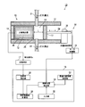
図1に示すように第1実施形態に係るβ線ガスモニタ10は、本体11内にβ線検出器12が配置され、本体11の内面に沿って移動可能な可変隔壁13により形成されたサンプル空間14に対して測定対象となるサンプルガスを導入するサンプラ部15と、設定された隔壁位置に可変隔壁13を移動させる隔壁駆動部16と、β線の検出信号sに基づいて計数率を計測する計数率計17と、可変隔壁13の位置設定、及び計測されたβ線の計数率に基づいてサンプルガスの放射能濃度を計算する計算機18と、を備える。
以下、本発明の実施形態を添付図面に基づいて説明する。
図1に示すように第1実施形態に係るβ線ガスモニタ10は、本体11内にβ線検出器12が配置され、本体11の内面に沿って移動可能な可変隔壁13により形成されたサンプル空間14に対して測定対象となるサンプルガスを導入するサンプラ部15と、設定された隔壁位置に可変隔壁13を移動させる隔壁駆動部16と、β線の検出信号sに基づいて計数率を計測する計数率計17と、可変隔壁13の位置設定、及び計測されたβ線の計数率に基づいてサンプルガスの放射能濃度を計算する計算機18と、を備える。
第1実施形態に係るβ線ガスモニタ10は、サンプルガスから放出されるβ線のエネルギー(以下、特に明示しない場合は平均エネルギーを意味する)に応じて、β線の計測に最適な位置に可変隔壁13を移動させサンプルガスの放射能濃度を求めるものである。
まず、サンプラ部15と隔壁駆動部16の構成について説明する。
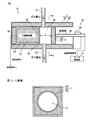
図2(A)はサンプラ部15及び隔壁駆動部16の構成を拡大した図であり、図2(B)は図2(A)のI―I断面を示している。
図2(A)はサンプラ部15及び隔壁駆動部16の構成を拡大した図であり、図2(B)は図2(A)のI―I断面を示している。
サンプラ部15は、本体11と、β線検出器12と、可変隔壁13と、背面遮蔽プラグ19と、入射窓20と、ガス導入ライン21と、ガス排出ライン22と、を備えている。
本体11は、内部が中空状に形成されており、一方の開放端が背面遮蔽プラグ19により密閉されている。本体11は、鉛などの放射線を遮断する材料で構成され円柱状の空洞が内部に形成された基体23と、鉄などのコーティング材料で基体23の表面全体を被覆した保護層24から構成されている。
本体11は、例えば直方体の鉛ブロックを、円柱状にくりぬいて、その外側と、くりぬいた後の内側を鉄などのコーティング材料で被覆して作製できる。
背面遮蔽プラグ19は、本体11と同様に、鉛などの放射線を遮断する材料で構成された基板を、鉄などのコーティング材料で表面が保護されて形成されている。本体11の開放端に背面遮蔽プラグ19が溶接などにより接続されることで、本体11の一方の開放端が密閉される。
β線検出器12は、検出口25を本体11の開放側に向けて、本体11内部に挿入される。そして、背面遮蔽プラグ19または本体11の側面に固定部材(図示省略)を介して固定され配置される。
β線検出器12は、β線が入射すると蛍光を発するプラスチックシンチレータと、シンチレータで発生した光を電気信号に変換して出力する光電子増倍管が接続されて構成された円筒型の検出器である。
β線検出器12は、円形状の検出口25が形成された検出器ケース26に収容される。検出器ケース26は、検出器内への光の入射を防止するためアルミニウムなどの遮光材料で構成される。
β線検出器12は、検出口25側にプラスチックシンチレータが配置され、検出口25から遠い位置に光電子増倍管が配置される。
β線検出器12は、計数率計17(図1)と電気的に接続されており、β線を検出して、β線が検出された際に発生する検出信号sを計数率計17に出力する。β線検出器12には、計数率計17から電源が供給される。
なお、β線検出器12としては、プラスチックシンチレータと光電子増倍管との組み合わせに限定されるものでは無く、ガス中から放出されるβ線を電気信号に変換して検出する電離箱、GM管などを用いても良い。
入射窓20は、鉄などの材料による円形状の板材であり、中心位置にβ線検出器12の検出口25よりも大きな径を有する開口部が形成されている。入射窓20は、サンプル空間14の境界を構成するため、β線検出器12の検出面側で検出器ケース26の近傍または接触して設けられる。
可変隔壁13は、本体11の内径より小さい径(本体11の内面を摺動可能な径)を有する円形状の板材である。そして、β線検出器12の検出口25に対向する位置に配置されて、本体11の内面を本体11の軸方向に沿って移動可能に設けられる。
なお、可変隔壁13は、本体11と同様に、鉛などの放射線を遮断する材料の隔壁基体27を鉄などのコーティング材料の隔壁被覆層28で表面が保護されている。
可変隔壁13は、本体11の内面及び入射窓20とともに外部空間との境界を構成して、外部空間と隔てられたサンプル空間14を形成する。
可変隔壁13が、隔壁駆動部16により本体11の内面を軸方向に沿って前後に移動されることで、入射窓20から可変隔壁13までの距離(以下、隔壁位置とする)及びサンプル空間14の体積が変更できる。なお、隔壁位置は、β線検出器12の検出口25から可変隔壁13までの距離としても良い。
ガス導入ライン21は、ガス導入時に開放される開放弁が設けられている。同様に、ガス排出ライン22には、排気用ポンプと、ガス排出時に開放される開放弁が設けられている。なお、排気用のポンプと各ラインに設けられる開放弁については図示を省略する。
放射能濃度測定時には、排気用のポンプを駆動してガス導入ライン21を介してサンプル空間14にサンプルガスを導入してサンプル空間14内にガスを充填しつつ、ガス排出ライン22を介してサンプル空間14内のサンプルガスを排出する。
隔壁駆動部16は、可変隔壁13に連結された駆動軸29と、駆動軸29を前後に駆動させるステッピングモータ30と、計算機18(図1)で設定された隔壁位置Lに可変隔壁13を移動させるための位置制御信号をステッピングモータ30に送信するモータ制御部31と、を備えている。
ステッピングモータ30による回転運動を駆動軸29によって可変隔壁13を前進・後退させる直線運動に変換される。なお、駆動軸29及びステッピングモータ30に代えて、油圧あるいは空圧シリンダー等を用いて可変隔壁13の前後動を実現しても良い。なお、計算機18から隔壁位置Lを設定するのでは無く、モータ制御部31がユーザによる入力を受け付け可能な構成にして、ユーザにより設定された隔壁位置Lに可変隔壁13を移動させても良い。
図1に戻って説明を続ける。
計算機18は、入力部32と、最適位置情報保存部33と、隔壁位置設定部34と、計数率受付部35と、放射能濃度計算部36と、を備える。
計算機18は、入力部32と、最適位置情報保存部33と、隔壁位置設定部34と、計数率受付部35と、放射能濃度計算部36と、を備える。
入力部32は、サンプルガスから放出されるβ線のエネルギーの入力をユーザから受け付ける。具体的には、放射性核種のそれぞれがβ線崩壊する際に生じるβ線のエネルギーとの対応関係に基づき、サンプルガス中に含まれると想定される放射線核種のβ線のエネルギーをユーザから受け付ける。また、ユーザから放射性核種の種類を受け付けて、その核種がβ線崩壊する際に生じるβ線のエネルギーを隔壁位置設定部34に出力する構成としても良い。
最適位置情報保存部33は、設定されたβ線のエネルギーのそれぞれに応じて隔壁位置Lの最適位置を、シミュレーション計算により予め求めて最適位置情報として保存する。設定されるβ線のエネルギーは、放出が想定されるβ線のエネルギーの範囲で複数設定される。
この最適位置情報を求めるためのシミュレーション計算は、β線のエネルギー及び隔壁位置Lをパラメータとして、サンプラ部15の詳細な構成を計算条件にして、PHITSやMCNP、EGS5などのモンテカルロ計算コードを用いて行われる。これらの計算コードを用いることで、複雑な設定条件におけるβ線検出器12の応答が高い精度で求められる。
図3は、電子のエネルギーを0.1、0.2、0.3、0.5、及び1.0MeVとした場合のβ線ガスモニタ10の検出効率をシミュレーション計算した結果を示している。
なお、シミュレーション計算には、モンテカルロ計算コードであるPHITSを用いて、各設定における計算のヒストリー数を100,000としている。なお、検出効率の単位は、cps/(Bq/cm3)で示している。
また、サンプラ部15の設定条件として、β線検出器12の検出口25の直径を200mm、入射窓20における開口部位の直径を210mm、サンプル空間14の直径を280mmとして、それぞれの中心は同一の軸上を通るものとしている。そして、β線検出器12のプラスチックシンチレータの厚さを0.25mm、保護膜の厚さを0.044mmとする。
このような構成で、可変隔壁13の隔壁位置Lを変化させて、β線のエネルギーごとに検出効率を計算している。
図4は、図3で示した計算結果に対して、可変隔壁13の設定位置が100cmでの検出効率を1とし、各検出効率を相対値で示したグラフである。
図4の結果から分かるように、最もエネルギーが低い0.1MeVについては、可変隔壁13の位置が10cm程度で検出効率は飽和する一方、それよりも高い他のエネルギーでは可変隔壁13の位置が10cm程度では飽和せず、より隔壁位置Lが大きい場合(可変隔壁13の位置が検出口25から遠い場合)に高い検出効率が得られる。
つまり、β線のエネルギーごとに計測に最適となる隔壁位置Lは異なり、低エネルギーのβ線を放出するガスの場合には、隔壁位置Lが小さい場合であっても高い検出効率が得られる。さらに、サンプル空間14内のガスの入れ替えが早くなることから検出器の応答時間も早くすることができる。
一方、高エネルギーのβ線を放出するガスの場合には、隔壁位置Lを大きくすることで、サンプル空間14の体積が増加することで検出器の応答時間は遅くなるものの、高い検出効率を得ることができる。
したがって、β線のエネルギーが100keV程度のβ線を放出する核種を含むガスの測定する場合には、隔壁位置L=10cmを最適位置となる一方で、100keVよりも高いエネルギーのβ線を放出する核種を含むガスの測定については隔壁位置L=20cm~45cmが最適位置となる。
このようなシミュレーション計算を行うことで、β線のエネルギーのそれぞれに対して、β線検出器12の検出効率及び検出の応答時間の少なくとも一方が高くなる(一定の目標値を超える)可変隔壁13の最適位置を求めて最適位置情報保存部33に保存する。
隔壁位置設定部34(図1)は、最適位置情報保存部33に保存された最適位置情報を参照して、入力されたβ線のエネルギーに対応する最適位置を、可変隔壁13の隔壁位置Lに設定する。
隔壁位置設定部34により設定された隔壁位置Lに可変隔壁13が移動されて、サンプル空間14にサンプルガスが導入された後、測定が開始される。
計数率計17は、β線検出器12で検出されたβ線の検出信号sに基づいて計数率を計測する。計測された計数率は、計算機18の計数率受付部35に送信される。
放射能濃度計算部36は、計測された計数率及びサンプル空間14の体積に基づいてサンプルガスの放射能濃度を計算する。
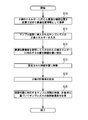
図5は、第1実施形態に係るβ線ガスモニタ10の動作手順を示すフローチャートを示している(適宜、図1参照)。
最適位置情報保存部33は、設定されたβ線のエネルギーに応じた最適な隔壁位置を計算で求めて最適位置情報として保存する(S10)。
入力部32は、サンプルガスから放出されるβ線のエネルギーの入力をユーザから受け付ける(S11)。
隔壁位置設定部34は、最適位置情報を参照して入力されたβ線エネルギーに対応する位置を隔壁位置に設定する(S12)。
隔壁駆動部16は、設定された隔壁位置に可変隔壁13に移動させる(S13)。そして、サンプル空間14にサンプルガスが導入された後、測定が開始される。
計数率計17は、β線検出器12で検出されたβ線の検出信号sに基づいて計数率を計測する(S14)。
放射能濃度計算部36は、隔壁位置に対応するサンプル空間14の体積及び計測された計数率に基づいてサンプルガスの放射能濃度を計算する(S15)。
このように、β線のエネルギーに応じた最適な隔壁位置を計算で求めておき、測定対象となるガスにおけるβ線のエネルギーに対応する隔壁位置に可変隔壁13を移動させることにより、最適な測定条件下で放射能濃度の監視を行うことができる。
(第2実施形態)
図6は、第2実施形態に係るβ線ガスモニタ10の構成図を示している。なお、図6において第1実施形態(図1)と共通の構成又は機能を有する部分は、同一符号で示し、重複する説明を省略する。
図6は、第2実施形態に係るβ線ガスモニタ10の構成図を示している。なお、図6において第1実施形態(図1)と共通の構成又は機能を有する部分は、同一符号で示し、重複する説明を省略する。
第1実施形態では、測定対象であるガスから放出されるβ線のエネルギーが既知の場合について放射能濃度の監視を行う構成について説明した。一方、第2実施形態では、ガスに含まれる核種の成分が不明な場合において、ガス中から放出されるβ線のエネルギーを推定する方法について説明する。
図4の計算結果から、例えば可変隔壁13の隔壁位置が5cmの場合でのβ線の計数率と、隔壁位置が20cmの場合でのβ線計数率の比率は、β線のエネルギーが高い場合と低い場合とで異なる事が分かる。つまり、隔壁位置間のβ線計数率の比率は、β線のエネルギーに応じて異なる値を持つ。
この性質を利用して、第2実施形態では、複数の隔壁位置でβ線計数率を計測し、隔壁位置間のβ線計数率の比率に基づいてβ線のエネルギーを推定する。
第2実施形態に係る計算機18は、隔壁位置変更部37と、データ関連付け部38と、比率計算部39と、相関情報保存部40と、照合部41と、表示部42と、をさらに備える。
隔壁位置変更部37は、複数の隔壁位置を設定する。隔壁位置変更部37は、設定された隔壁位置に可変隔壁13が移動されて、濃度の測定が完了した後に、次の隔壁位置に設定を変更する。
データ関連付け部38は、設定された隔壁位置とそれぞれの隔壁位置で計測された計数率とを関連付ける。
比率計算部39は、複数の位置での隔壁位置で測定が終了した後、隔壁位置間における計数率の比率を計算する。
相関情報保存部40(図6)は、設定された隔壁位置間での計数率の比率を、β線のエネルギーのそれぞれに応じて予めシミュレーション計算により求めて相関情報として保存する。シミュレーション計算上で設定する隔壁位置は、隔壁位置変更部37で設定される位置と同一の位置に設定する。
相関情報を求めるためのシミュレーション計算は、上述の最適位置情報と同じくβ線のエネルギー及び隔壁位置をパラメータとして、サンプラ部15の詳細な構成を計算条件にして、PHITSやMCNP、EGS5などのモンテカルロ計算コードを用いて行う。
照合部41は、比率計算部39で計算された比率を、同一の隔壁位置間における相関情報の比率と照合して、合致する比率に対応するβ線のエネルギーを出力する。表示部42は、出力されたβ線のエネルギーを推定値として表示する。
図7を用いて計数率の比率を導出してβ線のエネルギーを導出する過程を具体的に説明する。ここでは、隔壁位置変更部37によりL1、L2の2箇所に隔壁位置が設定された場合について検討する。
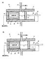
図7(A)は隔壁位置がL1の場合のサンプラ部15の状態を示しており、図7(B)は隔壁位置がL2の場合におけるサンプラ部15の状態を示している。
まず、隔壁位置変更部37により隔壁位置がL1に設定されたとき、隔壁の移動が完了した後に、サンプル空間A1にサンプルガスが導入される。そして、β線の検出信号s1に基づく計数率が計測される。データ関連付け部38は、隔壁位置L1に対応して検出信号s1に基づく計数率を関連づける。
隔壁位置がL1での測定終了後、隔壁位置変更部37により隔壁位置がL2に変更されて、隔壁の移動が完了した後に、サンプル空間A2にサンプルガスが導入される。そして、β線の検出信号s2に基づく計数率が計測される。データ関連付け部38は、隔壁位置L2に対応して検出信号s2に基づく計数率を関連づける。
比率計算部39は、隔壁位置L1と隔壁位置L2における計数率の比率を計算する。
照合部41は、比率計算部39で計算された比率を、相関情報保存部40でβ線のエネルギーごとに保存されている、隔壁位置L1、L2間での計数率の比率と照合する。そして、照合部41は、合致する比率に対応するβ線のエネルギーを出力する。
照合部41は、比率計算部39で計算された比率を、相関情報保存部40でβ線のエネルギーごとに保存されている、隔壁位置L1、L2間での計数率の比率と照合する。そして、照合部41は、合致する比率に対応するβ線のエネルギーを出力する。
なお、隔壁位置変更部37で設定される隔壁位置は、より複数の比率を取得することにより照合の精度が高くなることからより多くの位置に設定されることが望ましい。
図8は、第2実施形態に係るβ線ガスモニタ10の動作手順を示すフローチャートを示している(適宜、図6参照)。
相関情報保存部40は、設定された隔壁位置間における計数率の比率を、β線エネルギーのそれぞれに応じて予め計算により求めて相関情報として保存する(S20)。
隔壁位置変更部37は、可変隔壁13の隔壁位置を変更する。このとき、変更された隔壁位置のそれぞれでβ線の計数率が計測される(S21)。
データ関連付け部38は、設定された隔壁位置とそれぞれの隔壁位置で計測された計数率とを関連付ける(S22)。
比率計算部39は、隔壁位置間における計数率の比率を計算する(S23)。
照合部41は、計算された比率を、同一の隔壁位置間における相関情報の比率と照合する(S24)。
照合部41は、合致する比率に対応するβ線のエネルギーを出力する(S25)。表示部42は、出力されたβ線のエネルギーを推定値として表示する。
このように、複数の隔壁位置でβ線計数率を計測して、隔壁位置間のβ線計数率の比率を求めることにより、未知であったβ線のエネルギーを推定することができる。
また、相関情報保存部40は、設定された隔壁位置間における計数率の比率を、異なる放射性核種の連続エネルギーのそれぞれに応じて予め計算により求めて相関情報として保存しても良い。
この場合は、照合部41で、比率計算部39で計算された比率を照合することにより、放射性核種を推定することができる。
あるいは、相関情報保存部40は、隔壁位置間における計数率の比率を、サンプルガス中に複数種の放射線核種が混在すると仮定して、設定された放射線核種の組成比のそれぞれに応じて予め計算により求めて相関情報として保存しても良い。なお、複数種の放射性核種が混在する場合の連続エネルギーは、個別の放射性核種の連続エネルギーの組み合わせにより計算する。
そして、照合部41は、比率計算部39で計算された比率を、同一の隔壁位置間における相関情報の比率と照合して、合致する比率に対応する組成比を出力する。
このように、複数の隔壁位置でβ線計数率を計測して、隔壁位置間のβ線計数率の比率を求めることにより、放射性核種の推定または複数種の放射線核種が混在する場合に組成比の推定をすることもできる。
(第3実施形態)
図9は、第3実施形態に係るβ線ガスモニタ10に適用されるサンプラ部15の構成図を示している。なお、第3実施形態におけるβ線ガスモニタ10の全体構成は、第2実施形態(図6)と同一となるため記載を省略して、重複する構成又は機能については説明を省略する。
図9は、第3実施形態に係るβ線ガスモニタ10に適用されるサンプラ部15の構成図を示している。なお、第3実施形態におけるβ線ガスモニタ10の全体構成は、第2実施形態(図6)と同一となるため記載を省略して、重複する構成又は機能については説明を省略する。
第3実施形態に係るおけるβ線ガスモニタ10は、サンプル空間14にサンプルガスを導入するガス導入ライン21、及びサンプル空間14からサンプルガスを排出するガス排出ライン22のそれぞれに逆止弁43を有する。
逆止弁43を有することにより、可変隔壁13の前後動により自動的に吸排気ができる。これにより、排気用のポンプを省略して、β線ガスモニタ10の構成を簡素化できる。
また、第2実施形態のように複数の隔壁位置でβ線計数率を計測して隔壁位置間のβ線計数率の比率を求める際に、計数率の取得を連続的に求めることができる。これにより、β線のエネルギーの推定を短時間で実施することができる。
以上述べた各実施形態のβ線モニタによれば、β線のエネルギーに応じた最適な隔壁位置を計算で求めておき、測定対象となるガスのβ線のエネルギーに対応する隔壁位置に可変隔壁13を移動させることにより、測定されるβ線を放出する核種を含むガスに対して適した測定条件下で放射能濃度の監視を行うことができる。また、β線のエネルギーが未知の場合であっても、複数のサンプルボリュームで計測された計数率の比率に基づきβ線のエネルギーを推定することができる。
本発明のいくつかの実施形態を説明したが、これらの実施形態は、例として提示したものであり、発明の範囲を限定することは意図していない。これら新規な実施形態は、その他の様々な形態で実施されることが可能であり、発明の要旨を逸脱しない範囲で、種々の省略、置き換え、変更を行うことができる。これら実施形態やその変形は、発明の範囲や要旨に含まれるとともに、特許請求の範囲に記載された発明とその均等の範囲に含まれる。
なお、計算機18の各構成は、所定のプログラムコードを、プロセッサなどの電子回路において実行することによって実現しても良く、このようなソフトウェア処理に限らず、例えば、ASIC等の電子回路を用いたハードウェア処理で実現したユニットあるいは計算機として構成しても良いし、ソフトウェア処理とハードウェア処理とを組み合わせて実現したユニットあるいは計算機として構成しても良い。
10…β線ガスモニタ、11…本体、12…β線検出器、13…可変隔壁、14(141,142)…サンプル空間、15…サンプラ部、16…隔壁駆動部、17…計数率計、18…計算機、19…背面遮蔽プラグ、20…入射窓、21…ガス導入ライン、22…ガス排出ライン、23…基体、24…保護層、25…検出口、26…検出器ケース、27…隔壁基体、28…隔壁被覆層、29…駆動軸、30…ステッピングモータ、31…モータ制御部、32…入力部、33…最適位置情報保存部、34…隔壁位置設定部、35…計数率受付部、36…放射能濃度計算部、37…隔壁位置変更部、38…データ関連付け部、39…比率計算部、40…相関情報保存部、41…照合部、42…表示部、43…逆止弁、39…比率計算部、40…相関情報保存部、41…照合部、42…表示部、43…逆止弁、s(s1,s2)…検出信号、L(L1,L2)…隔壁位置。
Claims (9)
- 一方の開放端が密閉された中空状の本体と、
前記本体の内部に配置されて、β線を検出し、検出信号を出力するβ線検出器と、
前記β線検出器の検出口に対向する位置に前記本体の内面に沿って移動可能に設けられるものであって、測定するサンプルガスに対応する隔壁位置に設定されて、外部空間と隔てられたサンプル空間を前記本体の内面とともに形成する可変隔壁と、
前記サンプル空間に導入された前記サンプルガスから検出された前記検出信号に基づいて計数率を計測する計数率計と、
計測された前記計数率及び前記サンプル空間の体積に基づいて前記サンプルガスの放射能濃度を求める放射能濃度計算部と、を備えることを特徴とするβ線ガスモニタ。 - 前記可変隔壁を前記隔壁位置に移動させる隔壁駆動部をさらに備えることを特徴とする請求項1に記載のβ線ガスモニタ。
- 設定されたβ線のエネルギーのそれぞれに応じて前記隔壁位置の最適位置を予め計算により求めて最適位置情報として保存する最適位置情報保存部と、
前記最適位置情報を参照して、入力された前記サンプルガスにおけるβ線のエネルギーに対応する前記最適位置を、前記隔壁位置に設定する隔壁位置設定部と、をさらに備えることを特徴とする請求項1に記載のβ線ガスモニタ。 - 前記隔壁位置を複数設定する隔壁位置変更部と、
設定された前記隔壁位置とそれぞれの前記隔壁位置で計測された前記計数率とを関連付けるデータ関連付け部と、
隔壁位置間における前記計数率の比率を計算する比率計算部と、をさらに備えることを特徴とする請求項1に記載のβ線ガスモニタ。 - 前記隔壁位置間における前記計数率の比率を、設定されたβ線のエネルギーのそれぞれに応じて求めて相関情報として保存する相関情報保存部と、
前記比率計算部で計算された比率を、同一の前記隔壁位置間における前記相関情報の比率と照合して、合致する比率に対応するβ線のエネルギーを出力する照合部と、をさらに備えることを特徴とする請求項4に記載のβ線ガスモニタ。 - 前記隔壁位置間における前記計数率の比率を、異なる放射性核種の連続エネルギーのそれぞれに応じて求めて相関情報として保存する相関情報保存部と、
前記比率計算部で計算された比率を、同一の前記隔壁位置間における前記相関情報の比率と照合して、合致する比率に対応する前記放射性核種を出力する照合部と、をさらに備えることを特徴とする請求項4に記載のβ線ガスモニタ。 - 前記隔壁位置間における前記計数率の比率を、前記サンプルガス中に複数の放射線核種が混在すると仮定して、放射線核種の組成比のそれぞれに応じて求めて相関情報として保存する相関情報保存部と、
前記比率計算部で計算された比率を、同一の前記隔壁位置間における前記相関情報の比率と照合して、合致する比率に対応する前記組成比を出力する照合部と、をさらに備えることを特徴とする請求項4に記載のβ線ガスモニタ。 - 前記サンプル空間に前記サンプルガスを導入するガス導入ライン及び前記サンプル空間から前記サンプルガスを排出するガス排出ラインのそれぞれに逆止弁を設けることを特徴とする請求項1に記載のβ線ガスモニタ。
- 一方の開放端が密閉された中空状の本体と、前記本体の内部に配置されて、β線を検出し、検出信号を出力するβ線検出器と、前記β線検出器の検出口に対向する位置に前記本体の内面に沿って移動可能に設けられるものであって、測定するサンプルガスに対応する隔壁位置に設定されて、外部空間と隔てられたサンプル空間を前記本体の内面とともに形成する可変隔壁を用いて、
前記サンプル空間に導入された前記サンプルガスから検出された前記検出信号に基づいて計数率を計測するステップと、
計測された前記計数率及び前記サンプル空間の体積に基づいて前記サンプルガスの放射能濃度を求めるステップと、を含むことを特徴とするβ線を放出する核種を含むガスのモニタリング方法。
Applications Claiming Priority (2)
| Application Number | Priority Date | Filing Date | Title |
|---|---|---|---|
| JP2015250508A JP2017116349A (ja) | 2015-12-22 | 2015-12-22 | β線ガスモニタ及びβ線を放出する核種を含むガスのモニタリング方法 |
| JP2015-250508 | 2015-12-22 |
Publications (1)
| Publication Number | Publication Date |
|---|---|
| WO2017110682A1 true WO2017110682A1 (ja) | 2017-06-29 |
Family
ID=59090291
Family Applications (1)
| Application Number | Title | Priority Date | Filing Date |
|---|---|---|---|
| PCT/JP2016/087576 Ceased WO2017110682A1 (ja) | 2015-12-22 | 2016-12-16 | β線ガスモニタ及びβ線を放出する核種を含むガスのモニタリング方法 |
Country Status (2)
| Country | Link |
|---|---|
| JP (1) | JP2017116349A (ja) |
| WO (1) | WO2017110682A1 (ja) |
Cited By (1)
| Publication number | Priority date | Publication date | Assignee | Title |
|---|---|---|---|---|
| CN114127584A (zh) * | 2019-07-15 | 2022-03-01 | 俄罗斯国家原子能公司 | 监测放射性废物中放射性核素含量的方法 |
Citations (7)
| Publication number | Priority date | Publication date | Assignee | Title |
|---|---|---|---|---|
| JPS5950343A (ja) * | 1982-09-14 | 1984-03-23 | Yokogawa Hokushin Electric Corp | 光路長変調形分析計 |
| JPS59138785U (ja) * | 1983-03-08 | 1984-09-17 | 株式会社東芝 | 放射性ガス採取装置 |
| JPS61272679A (ja) * | 1985-05-29 | 1986-12-02 | Hitachi Ltd | 放射性ガス測定容器 |
| JPH1164527A (ja) * | 1997-08-11 | 1999-03-05 | Fuji Electric Co Ltd | ガスモニタ及び水モニタ |
| JP2001524210A (ja) * | 1997-04-16 | 2001-11-27 | エービービー・アトム・エービー | 放射性不活性ガスの核種含有量を測定するための装置 |
| WO2012029510A1 (ja) * | 2010-08-31 | 2012-03-08 | 三菱重工業株式会社 | 原子炉燃料健全性モニタ |
| JP2015143663A (ja) * | 2014-01-31 | 2015-08-06 | 三菱電機株式会社 | 放射性ガスモニタ |
-
2015
- 2015-12-22 JP JP2015250508A patent/JP2017116349A/ja active Pending
-
2016
- 2016-12-16 WO PCT/JP2016/087576 patent/WO2017110682A1/ja not_active Ceased
Patent Citations (7)
| Publication number | Priority date | Publication date | Assignee | Title |
|---|---|---|---|---|
| JPS5950343A (ja) * | 1982-09-14 | 1984-03-23 | Yokogawa Hokushin Electric Corp | 光路長変調形分析計 |
| JPS59138785U (ja) * | 1983-03-08 | 1984-09-17 | 株式会社東芝 | 放射性ガス採取装置 |
| JPS61272679A (ja) * | 1985-05-29 | 1986-12-02 | Hitachi Ltd | 放射性ガス測定容器 |
| JP2001524210A (ja) * | 1997-04-16 | 2001-11-27 | エービービー・アトム・エービー | 放射性不活性ガスの核種含有量を測定するための装置 |
| JPH1164527A (ja) * | 1997-08-11 | 1999-03-05 | Fuji Electric Co Ltd | ガスモニタ及び水モニタ |
| WO2012029510A1 (ja) * | 2010-08-31 | 2012-03-08 | 三菱重工業株式会社 | 原子炉燃料健全性モニタ |
| JP2015143663A (ja) * | 2014-01-31 | 2015-08-06 | 三菱電機株式会社 | 放射性ガスモニタ |
Cited By (2)
| Publication number | Priority date | Publication date | Assignee | Title |
|---|---|---|---|---|
| CN114127584A (zh) * | 2019-07-15 | 2022-03-01 | 俄罗斯国家原子能公司 | 监测放射性废物中放射性核素含量的方法 |
| CN114127584B (zh) * | 2019-07-15 | 2025-06-17 | 俄罗斯国家原子能公司 | 监测放射性废物中放射性核素含量的方法 |
Also Published As
| Publication number | Publication date |
|---|---|
| JP2017116349A (ja) | 2017-06-29 |
Similar Documents
| Publication | Publication Date | Title |
|---|---|---|
| EP2077457B1 (en) | Radiation dosimeter and radiation dose computing program | |
| JP6475931B2 (ja) | 放射性物質のモニタリング装置及び放射性物質のモニタリング方法 | |
| US11035963B2 (en) | Method for detecting radionuclide, process for detecting radionuclide using the same, and radiation detector for the same | |
| US7595494B2 (en) | Direction-sensitive radiation detector and radiation detection method | |
| JP6448466B2 (ja) | 放射性ガスモニタリング装置 | |
| US9448309B2 (en) | Method and apparatus for detection of radioactive isotopes | |
| WO2017110682A1 (ja) | β線ガスモニタ及びβ線を放出する核種を含むガスのモニタリング方法 | |
| JP4061367B2 (ja) | ZnS(Ag)シンチレーション検出器 | |
| US11056333B2 (en) | Spectrometry method and device for detecting ionising radiation for the implementation thereof | |
| JP2017505437A (ja) | 放射性物体中のベリリウムの量を測定するための装置 | |
| JP3542936B2 (ja) | 放射線測定装置 | |
| Baccarelli et al. | Standardization of $^{18} $ F by Means of $4\pi ({\rm PS})\beta-\gamma $ Plastic Scintillator Coincidence System | |
| JP5450356B2 (ja) | 放射線検出方法 | |
| RU2390800C2 (ru) | Способ и устройство для измерения спектральной и интегральной плотности потока нейтронов | |
| JP7422032B2 (ja) | 放射性核種の製造システム及び方法 | |
| JP6443987B2 (ja) | 放射線の遮蔽能力試験方法及びこれに用いる容器 | |
| US11747489B2 (en) | Dosimeter | |
| JP7750528B2 (ja) | 信号処理システム、陽電子放射断層撮影装置及び陽電子放射断層撮影方法 | |
| Toh et al. | A position-sensitive particle detector for Coulomb excitation experiment | |
| JP2017151046A (ja) | 放射性物質の線源効率測定装置 | |
| RU157406U1 (ru) | Сцинтилляционный детектор гамма-излучения | |
| Christodoulou | Development and optimisation of a liquid argon detector as a prototype liquid argon Positron Emission Tomography photon detector | |
| Yamamoto et al. | Evaluation of γ-ray Effects on a β-ray Survey Meter with a Plastic Scintillation Sensor | |
| SU943623A1 (ru) | Способ определени параметров электронно-ионных колец | |
| Dejesus | Characteristics of High Reliability TEPC for Long Term Space Missions |
Legal Events
| Date | Code | Title | Description |
|---|---|---|---|
| 121 | Ep: the epo has been informed by wipo that ep was designated in this application |
Ref document number: 16878571 Country of ref document: EP Kind code of ref document: A1 |
|
| NENP | Non-entry into the national phase |
Ref country code: DE |
|
| 122 | Ep: pct application non-entry in european phase |
Ref document number: 16878571 Country of ref document: EP Kind code of ref document: A1 |