WO2017110344A1 - エネルギ安定化装置 - Google Patents
エネルギ安定化装置 Download PDFInfo
- Publication number
- WO2017110344A1 WO2017110344A1 PCT/JP2016/084478 JP2016084478W WO2017110344A1 WO 2017110344 A1 WO2017110344 A1 WO 2017110344A1 JP 2016084478 W JP2016084478 W JP 2016084478W WO 2017110344 A1 WO2017110344 A1 WO 2017110344A1
- Authority
- WO
- WIPO (PCT)
- Prior art keywords
- energy
- energy storage
- power
- storage device
- generated power
- Prior art date
- Legal status (The legal status is an assumption and is not a legal conclusion. Google has not performed a legal analysis and makes no representation as to the accuracy of the status listed.)
- Ceased
Links
Images




Classifications
-
- H—ELECTRICITY
- H02—GENERATION; CONVERSION OR DISTRIBUTION OF ELECTRIC POWER
- H02J—ELECTRIC POWER NETWORKS; CIRCUIT ARRANGEMENTS OR SYSTEMS FOR SUPPLYING OR DISTRIBUTING ELECTRIC POWER; SYSTEMS FOR STORING ELECTRIC ENERGY
- H02J3/00—Circuit arrangements for AC mains or AC distribution networks
- H02J3/28—Arrangements for balancing of the load in networks by storage of energy
- H02J3/30—Arrangements for balancing of the load in networks by storage of energy using dynamo-electric machines coupled to flywheels
-
- H—ELECTRICITY
- H02—GENERATION; CONVERSION OR DISTRIBUTION OF ELECTRIC POWER
- H02J—ELECTRIC POWER NETWORKS; CIRCUIT ARRANGEMENTS OR SYSTEMS FOR SUPPLYING OR DISTRIBUTING ELECTRIC POWER; SYSTEMS FOR STORING ELECTRIC ENERGY
- H02J3/00—Circuit arrangements for AC mains or AC distribution networks
- H02J3/28—Arrangements for balancing of the load in networks by storage of energy
- H02J3/32—Arrangements for balancing of the load in networks by storage of energy using batteries or super capacitors with converting means
-
- H—ELECTRICITY
- H02—GENERATION; CONVERSION OR DISTRIBUTION OF ELECTRIC POWER
- H02J—ELECTRIC POWER NETWORKS; CIRCUIT ARRANGEMENTS OR SYSTEMS FOR SUPPLYING OR DISTRIBUTING ELECTRIC POWER; SYSTEMS FOR STORING ELECTRIC ENERGY
- H02J3/00—Circuit arrangements for AC mains or AC distribution networks
- H02J3/38—Arrangements for feeding a single network from two or more generators or sources in parallel; Arrangements for feeding already energised networks from additional generators or sources in parallel
-
- H—ELECTRICITY
- H02—GENERATION; CONVERSION OR DISTRIBUTION OF ELECTRIC POWER
- H02J—ELECTRIC POWER NETWORKS; CIRCUIT ARRANGEMENTS OR SYSTEMS FOR SUPPLYING OR DISTRIBUTING ELECTRIC POWER; SYSTEMS FOR STORING ELECTRIC ENERGY
- H02J3/00—Circuit arrangements for AC mains or AC distribution networks
- H02J3/38—Arrangements for feeding a single network from two or more generators or sources in parallel; Arrangements for feeding already energised networks from additional generators or sources in parallel
- H02J3/46—Controlling the sharing of generated power between the generators, sources or networks
-
- Y—GENERAL TAGGING OF NEW TECHNOLOGICAL DEVELOPMENTS; GENERAL TAGGING OF CROSS-SECTIONAL TECHNOLOGIES SPANNING OVER SEVERAL SECTIONS OF THE IPC; TECHNICAL SUBJECTS COVERED BY FORMER USPC CROSS-REFERENCE ART COLLECTIONS [XRACs] AND DIGESTS
- Y02—TECHNOLOGIES OR APPLICATIONS FOR MITIGATION OR ADAPTATION AGAINST CLIMATE CHANGE
- Y02E—REDUCTION OF GREENHOUSE GAS [GHG] EMISSIONS, RELATED TO ENERGY GENERATION, TRANSMISSION OR DISTRIBUTION
- Y02E70/00—Other energy conversion or management systems reducing GHG emissions
- Y02E70/30—Systems combining energy storage with energy generation of non-fossil origin
Definitions
- the present invention relates to an energy stabilization device that stably supplies generated power from a power generation device to an electric power system.
- Renewable energy such as wind power generation and solar power generation is expected to be used more and more in the future because it can reduce greenhouse gases such as carbon dioxide, prevent global warming, and there is no problem of radioactive contamination. It has been.
- the amount of power generated by renewable energy greatly fluctuates depending on time. Therefore, when the renewable energy is connected to the power system, the system voltage and frequency may fluctuate greatly.
- the above publication describes a power stabilization device that divides the output power of a power generator into a long-period component and a short-cycle component by a filter capable of adjusting a time constant, and stores energy in different power storage devices. .
- leveling the generated power When the generated power is used in the power system, it is necessary to monitor the generated power so that the system power in the power system does not fluctuate greatly due to power generation, and suppress sudden fluctuations in the generated power (hereinafter referred to as leveling the generated power). is there.
- the present invention has been made in view of the above-described problems, and can stabilize the energy storage amount of the storage device within the reference range and can level the generated power based on past performance data.
- a device is provided.
- an energy stabilization device that suppresses fluctuations in generated power output by a power generator of renewable energy linked to a power system
- a first energy storage device capable of storing energy according to the generated power output from the power generation device, and capable of supplying the power according to the stored energy together with the generated power to the power system
- a first accumulation amount monitoring unit for monitoring an energy accumulation amount of the first energy accumulation device
- a post-leveling generated power monitoring unit for monitoring the leveled generated power in the power system
- the first energy storage device based on the energy storage amount of the first energy storage device monitored by the first storage amount monitoring unit and the post-leveling generated power monitored by the leveled generated power monitoring unit.
- An accumulation control unit that controls the fluctuation value within a predetermined period of the leveled generated power that is set based on past performance data to be within a first reference range, An energy stabilization device is provided.
- the accumulation control unit When the energy storage amount of the first energy storage device approaches the upper limit within the first reference range, the accumulation control unit does not cause the fluctuation value of the leveled generated power within the predetermined period to exceed the predetermined value.
- the energy stored in the first energy storage device When the energy stored in the first energy storage device is released to the power system together with the generated power in the range, and the energy storage amount of the first energy storage device approaches the lower limit in the first reference range, The energy stored in the first energy storage device may be increased within a range in which the fluctuation value of the generated power after leveling within the predetermined period does not exceed the predetermined value.
- Energy can be stored in accordance with the generated power output from the power generation device, and power in accordance with the stored energy can be supplied to the power system together with the generated power, storing more energy than the first energy storage device.
- the accumulation control unit includes an energy accumulation amount of the first energy accumulation device monitored by the first accumulation amount monitoring unit, an energy accumulation amount of the second energy accumulation device monitored by the second accumulation amount monitoring unit, and Based on the power level of the post-leveling generated power monitored by the post-leveling generated power monitoring unit, the energy storage amount of the first energy storage device falls within a first reference range, and after the leveling
- the fluctuation value of the generated power within a predetermined period may be controlled to a predetermined value or less, and the energy storage amount of the second energy storage device may be controlled.
- the accumulation control unit performs control to accumulate energy in the first energy storage device according to the power of the frequency component less than the first frequency in the generated power output from the power generation device, and the energy is equal to or higher than the first frequency. You may perform control which accumulate
- the accumulation control unit performs control to accumulate energy in the first energy storage device according to the power of the frequency component less than the first frequency and greater than or equal to the second frequency among the generated power output from the power generation device, You may perform control which accumulate
- a filter for filtering a power generation state signal according to the generated power output from the power generation device may be provided,
- the accumulation control unit includes an energy accumulation amount of the first energy accumulation device monitored by the first accumulation amount monitoring unit, an energy accumulation amount of the second energy accumulation device monitored by the second accumulation amount monitoring unit, and Based on the above, the first frequency and the second frequency may be set by variably controlling a time constant for determining the frequency characteristic of the filter.
- the limit number of energy storage / release in the first energy storage device may be smaller than the limit number of energy storage / release in the second energy storage device.
- the response speed of energy storage / release in the first energy storage device may be slower than the response speed of energy storage / release in the second energy storage device.
- the first energy storage device may be a chemical battery.
- the second energy storage device may be a flywheel device that converts electric power generated by the power generation device into rotational energy and stores it, or a capacitor that stores electric charge according to the generated power.
- the first energy storage device and the second energy storage device may be different types of chemical batteries.
- the energy storage amount of the storage device falls within the reference range, and the generated power can be leveled based on the past performance data.
- FIG. 1 is a block diagram showing a schematic configuration of an energy stabilizing device 1 according to the first embodiment.
- the energy stabilization device 1 of FIG. 1 suppresses fluctuations in the generated power output by the renewable energy power generation device 2 linked to the power system.
- the power generation device 2 is a wind power generation device
- the generated power varies greatly with time.
- the generated power is leveled.
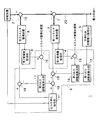
- first energy storage device 3 includes a first energy storage device 3, a first storage amount monitoring unit 4, a post-leveling generated power monitoring unit 5, a storage control unit 6, and a first power branching / merging unit. 7.
- the first energy storage device 3 can store energy corresponding to the generated power output from the power generation device 2.
- the electric power according to the energy stored in the first energy storage device 3 can be supplied to the power system together with the generated power.
- the first energy storage device 3 is preferably a secondary battery having a large energy storage capacity, such as a lithium ion battery.
- the first energy storage device 3 is monitored for the amount of energy stored, and the energy storage and release of the first energy storage device 3 are controlled as necessary. It is not necessary to increase the energy storage capacity of the storage device 3 so much. Thereby, an installation cost can be suppressed.
- the 1st energy storage device 3 should just be what can perform both energy storage and discharge
- the first accumulation amount monitoring unit 4 monitors the energy accumulation amount of the first energy accumulation device 3.
- the leveled generated power monitoring unit 5 monitors the leveled generated power 20 supplied to the power system. Monitoring by the first accumulation amount monitoring unit 4 and the leveled generated power monitoring unit 5 is performed constantly or periodically.
- the accumulation control unit 6 includes an energy accumulation amount of the first energy accumulation device 3 monitored by the first accumulation amount monitoring unit 4, a power level of the post-leveling generated power 20 monitored by the leveled generated power monitoring unit 5, and Based on the above, the energy storage amount of the first energy storage device 3 falls within the first reference range, and the fluctuation value within the predetermined period of the leveled generated power 20 set based on the past performance data is set to a predetermined value. Control to:
- the storage control unit 6 sets the fluctuation value within the predetermined period of the leveled generated power 20 to a predetermined value.
- the energy stored in the first energy storage device 3 is released together with the generated power to the power system within a range not exceeding, the energy storage amount of the first energy storage device 3 approaches the lower limit in the first reference range.
- the energy stored in the first energy storage device 3 is increased within a range in which the fluctuation value within the predetermined period of the leveled generated power 20 does not exceed the predetermined value.
- the first power branching / merging unit 7 performs power control for storing a part of the generated power 20 after leveling in the first energy storage device 3, and generated power after leveling the energy stored in the first energy storage device 3. And the power control that merges with 20 is performed.
- the accumulation control unit 6 includes an output leveling command unit 11, a first output adjustment value calculation unit 12, a first difference generator 13, a second output adjustment value calculation unit 14, and a second difference. And a generator 15.
- the output leveling command unit 11 generates and outputs a first command signal that commands the first energy storage device 3 to store or release energy based on the generated power so that the generated power is leveled.
- the first output adjustment value calculation unit 12 generates and outputs a first output adjustment value corresponding to the post-system level generated power 20 monitored by the post-level generation power monitoring unit 5.
- the first difference generator 13 is a difference between an energy storage amount of the first energy storage device 3 monitored by the first storage amount monitoring unit 4 and a predetermined energy storage target amount of the first energy storage device 3. One difference value is generated and output.
- the second output adjustment value calculation unit 14 generates and outputs a second output adjustment value based on the first output adjustment value and the first difference value.
- the second difference generator 15 performs first energy accumulation based on the first command signal output from the output leveling command unit 11 and the second output adjustment value output from the second output adjustment value calculation unit 14.
- a second command signal for commanding energy storage or release of the device 3 is generated and output.
- the first energy storage device 3 stores energy corresponding to the generated power from the power generation device 2 based on the second command signal, or releases the stored energy together with the generated power to the power system.
- FIG. 2 is a graph showing how the power level of the system power changes with time, with the horizontal axis representing time [minutes] and the vertical axis representing active power [W] of the system power. If the generated power fluctuates rapidly, the grid power may fluctuate accordingly. Even if the first energy storage device 3 for storing the generated power is provided as in the present embodiment, there is a time lag between energy storage in the first energy storage device 3 and energy release from the first energy storage device 3. Therefore, some fluctuations in system power are inevitable. Furthermore, if a load (not shown) that uses system power from the power system varies, the system power also varies.
- the leveled generated power monitoring unit 5 monitors the leveled generated power 20 constantly or periodically.
- the accumulation control unit 6 controls the energy accumulation amount of the first energy accumulation device 3 so that the fluctuation rate of the leveled generated power 20 within a predetermined period (for example, 20 minutes) does not exceed 10%, for example.
- the numerical values of the predetermined period and the fluctuation rate may be arbitrarily adjusted based on past performance data.
- the storage control unit 6 sets the energy storage amount of the first energy storage device 3 so that the energy storage amount of the first energy storage device 3 monitored by the first storage amount monitoring unit 4 falls within the first reference range.
- the first reference range may also be set based on past performance data. For example, the first reference range is 40 to 60% with respect to the total energy storage capacity of the first energy storage device 3.
- the storage control unit 6 uses the first storage amount monitoring unit 4 and finds that the energy storage amount of the first energy storage device 3 is likely to fall below 40%, the energy storage amount of the first energy storage device 3 In order to increase the energy, the energy storage process of the generated power in the first energy storage device 3 is performed.
- the storage control unit 6 monitors the leveled generated power 20 using the leveled generated power monitoring unit 5, and generates the leveled power generation.
- the amount of energy stored in the first energy storage device 3 is controlled so that the fluctuation rate of the power 20 within a predetermined period does not exceed a predetermined value.
- the accumulation control unit 6 uses the first accumulation amount monitoring unit 4 and finds that the energy accumulation amount of the first energy accumulation device 3 is likely to exceed 60%, the accumulation control unit 6 In order to reduce the energy storage amount, the energy release amount of the first energy storage device 3 is increased. Increasing the amount of energy released generally increases the level of generated power 20 after leveling. Therefore, when increasing the amount of energy released from the first energy storage device 3, the storage control unit 6 monitors the post-leveling generated power 20 using the post-leveling generated power monitoring unit 5, and generates post-leveling power generation. The amount of energy stored in the first energy storage device 3 is controlled so that the fluctuation rate of the power 20 within a predetermined period does not exceed a predetermined value.
- the energy accumulation amount of the first energy accumulation device 3 capable of accumulating and releasing energy according to the generated electric power is monitored by the first accumulation amount monitoring unit 4, and the power generation after leveling is performed.
- the power 20 is monitored by the generated power monitoring unit 5 after leveling, and based on these monitoring results, the energy storage amount of the first energy storage device 3 falls within the first reference range, and the generated power 20 after leveling 20
- the fluctuation value within a predetermined period is controlled to be equal to or less than a predetermined value.
- the generated power fluctuates rapidly or the load on the power system fluctuates rapidly. Even so, the generated power 20 after leveling can continue to maintain the leveling target.
- a second energy storage device is provided separately from the first energy storage device 3.
- FIG. 3 is a block diagram showing a schematic configuration of the energy stabilizing device 1 according to the second embodiment.
- the same reference numerals are given to components common to FIG. 1, and different points will be mainly described below.
- FIG. 3 includes a second energy storage device 8, a second storage amount monitoring unit 9, and a second power branching / merging unit 10 in addition to the configuration of FIG.
- the second energy storage device 8 can store energy corresponding to the generated power output from the power generation device 2.
- the electric power corresponding to the energy stored in the second energy storage device 8 can be supplied to the power system together with the generated power.
- the second energy storage device 8 has a smaller energy storage capacity than the first energy storage device 3.
- the second energy storage device 8 is, for example, a flywheel device 8.
- the flywheel device 8 converts the generated electric power into mechanical rotational energy and stores it.
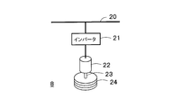
- FIG. 4 is a schematic block diagram for explaining the principle of the flywheel device 8.
- the flywheel device 8 in FIG. 4 includes an inverter 21, a motor / generator 22 connected to the inverter 21, and a flywheel 24 that rotates together with the rotating shaft 23 of the motor / generator 22.
- the inverter 21 is an AC-AC converter that converts the frequency of the generated power (leveled generated power 20) output from the power generator 2 in order to rotate the flywheel 24 at a high speed.
- the motor / generator 22 rotates the rotating shaft 23 by the output power of the inverter 21. At this time, the motor / generator 22 functions as a motor. Since the flywheel 24 is connected to the rotating shaft 23, the flywheel 24 also rotates when the rotating shaft 23 rotates.
- generated electric power can be converted into rotational energy of the flywheel 24.
- the rotational energy of the flywheel 24 can be used as electrical energy for driving the motor / generator 22 via the rotating shaft 23 as necessary.
- the motor / generator 22 functions as a generator.
- the generated power generated by the motor / generator 22 is used as the leveled generated power 20.
- the second energy storage device 8 in FIG. 3 is not necessarily limited to the flywheel device 11.
- a large-capacity capacitor capable of storing generated power as electric charge may be used.
- the second energy storage device 8 may be various secondary batteries (chemical batteries). As a typical secondary battery, for example, a lithium ion battery or a redox flow battery can be considered.
- the second energy storage device 8 may be the same type as the first energy storage device 3 or may be a different type. For example, different types of chemical batteries may be used as the first energy storage device 3 and the second energy storage device 8.
- the second storage amount monitoring unit 9 monitors the energy storage amount of the second energy storage device 8.
- the second energy storage device 8 has a smaller energy storage capacity than the first energy storage device 3, and the second energy storage device 8 is in a fully stored state than the first energy storage device 3. It is easy to become. Therefore, the accumulation control unit 6 controls the energy accumulation amount of the second energy accumulation device 8 using the second accumulation amount monitoring unit 9.
- the second power branch / merging unit 10 performs power control for storing a part of the generated power 20 after leveling in the second energy storage device 8 and generates the energy stored in the second energy storage device 8 after system leveling. Power control for joining the power 20 is performed.
- the accumulation control unit 6 in the energy stabilization device 1 of FIG. 3 includes an output leveling command unit 11 having a function added to the configuration of FIG. 1, a third difference generator 16, and a third output adjustment value calculation. A unit 17, a fourth difference generator 18, and a fifth difference generator 19.
- the output leveling command unit 11 stores energy in the first energy storage device 3 or the second energy storage device 8 for each frequency component included in the generated power based on the generated power so that the generated power is leveled. Alternatively, a command signal that commands release is generated and output.
- the third difference generator 16 is a difference between an energy storage amount of the second energy storage device 8 monitored by the second storage amount monitoring unit 9 and a predetermined energy storage target value of the second energy storage device 8. 2 A difference value is generated and output.
- the third output adjustment value calculation unit 17 generates and outputs a third output adjustment value and a fourth output adjustment value corresponding to the second difference value.
- the fourth difference generator 19 generates and outputs a third difference value that is a difference between the second command signal for the second energy storage device 8 output from the output leveling command unit 11 and the third output adjustment value. To do.
- the second energy storage device 8 stores energy corresponding to the generated power based on the third difference value, or releases the stored energy and supplies it to the power system together with the generated power.
- the fifth difference generator 18 generates and outputs a fourth difference value that is a difference between the third command signal for the first energy storage device 3 output from the output leveling command unit 11 and the fourth output adjustment value. To do. Based on the fourth difference value, the first energy storage device 3 stores energy corresponding to the generated power, or releases the stored energy and supplies it to the power system together with the generated power.
- the first energy storage device 3 mainly stores energy corresponding to power of a frequency component less than the first frequency (hereinafter, long-period component) out of the generated power output from the power generation device 2. .
- the first energy storage device 3 may mainly store energy corresponding to power of frequency components less than the first frequency and greater than or equal to the second frequency component, rather than all frequency components less than the first frequency.
- the first energy storage device 3 is, for example, a secondary battery (chemical battery) such as a lithium ion battery or a lead storage battery that can be easily increased in capacity.
- a secondary battery such as a lithium ion battery or a lead storage battery that can be easily increased in capacity.
- the first energy storage device 3 since the first energy storage device 3 mainly stores long-period components of the generated power, the first energy storage device 3 is more limited in energy storage / release than the second energy storage device 8.
- the number of times may be small. For example, the number of times of charging and discharging is limited to about several hundreds for a lithium ion battery, but the above-described first energy storage device 3 assumes that charging and discharging are not frequently performed.
- a secondary battery in which the number of times of charging / discharging is limited can be used.
- the second energy storage device 8 mainly stores the energy corresponding to the power of the first frequency or higher (hereinafter, short cycle component) among the generated power output from the power generation device 2.
- the second energy storage device 8 a flywheel device having excellent responsiveness is used.
- FIG. 5 is a diagram showing frequency characteristics of generated power, where the horizontal axis represents frequency and the vertical axis represents the output signal level of generated power.
- TF is the first frequency
- TH is the second frequency.
- the accumulation control unit 6 accumulates energy corresponding to the frequency component equal to or higher than the first frequency TF included in the generated power in the second energy storage device 8, and is less than the first frequency TF included in the generated power and equal to or higher than the second frequency TH. Control is performed to store energy corresponding to the frequency component of the first energy storage device 3.
- the storage control unit 6 controls the first frequency TF and the second frequency TH so that the energy storage amount of the second energy storage device 8 falls within a predetermined range equal to or less than the full capacity.
- the second energy storage device 8 has a smaller energy storage capacity than the first energy storage device 3, but has a higher number of energy storage / release limits than the first energy storage device 3 and is excellent in responsiveness. Therefore, it is desirable to store the energy corresponding to the short cycle component in the generated energy output from the power generator 2 in the second energy storage device 8 as much as possible. Thereby, the frequency
- the 2nd energy storage device 8 Energy can be stored. Thereby, it becomes easy to perform control to keep the energy storage amount of the first energy storage device 3 within the first reference range and to make the fluctuation value within the predetermined period of the leveled generated power 20 equal to or less than the predetermined value. Further, the second energy storage device 8 having a small energy storage capacity and excellent responsiveness is used for storing short-period components of the generated power, and the first energy storage device 3 having a large energy storage capacity is used for the generated power. Therefore, the frequency of energy storage / release of the first energy storage device 3 can be suppressed, and the life of the first energy storage device 3 can be extended.
- a filter is provided inside the accumulation control unit 6.
- FIG. 6 is a block diagram showing a schematic configuration of the energy stabilizing device 1 according to the third embodiment.
- the energy stabilizing device 1 of FIG. 6 includes a filter 11a inside the output leveling command unit 11, and a time constant setting unit 30 for setting the time constant of the filter 11a inside the accumulation control unit 6. Other than this, it is common to FIG.
- the filter 11 a Based on the power generation state signal from the power generation device 2, the filter 11 a generates a control signal that allocates the generated power output from the power generation device 2 to the first energy storage device 3 and the second energy storage device 8.
- the power generation state signal is a signal indicating the power generation amount output from the power generation device 2.
- the output leveling command unit 11 commands the energy storage in the first energy storage device 3 or the second energy storage device 8 for each frequency component included in the generated power based on the control signal from the filter 11a. Is generated and output.
- the filter 11a can be expressed by an equivalent transfer function, and TF and TH in FIG. 5 can be arbitrarily adjusted by controlling the time constant of the transfer function.
- the time constant setting unit 30 in the storage control unit 6 controls the time constant of the transfer function of the filter 11a based on the energy storage amounts of the first energy storage device 3 and the second energy storage device 8, thereby , TF and TH in FIG. 5 are adjusted.
- the accumulation control unit 6 accumulates the energy corresponding to the frequency component equal to or higher than the first frequency TF included in the generated power in the second energy storage device 8, and the second is less than the first frequency TF included in the generated power. Control is performed to store energy in the first energy storage device 3 according to a frequency component equal to or higher than the frequency TH.
- the frequency component of the generated power stored in the first energy storage device 3 and the second energy storage device 8 can be arbitrarily adjusted by providing the filter 11a capable of adjusting the time constant. . Therefore, the time constant of the filter 11a is adjusted by the time constant setting unit 30 according to the energy storage amount of the first energy storage device 3 and the second energy storage device 8 and the power level of the generated power 20 after the leveling. Thus, it is possible to level the generated power while adjusting the energy storage amounts of the first energy storage device 3 and the second energy storage device 8 to appropriate amounts.
- 1 energy stabilization device 1 energy stabilization device, 2 power generation device, 3rd energy storage device, 1st accumulation amount monitoring unit, 5 leveled generated power monitoring unit, 6 accumulation control unit, 7 1st power branching / merging unit, 11 output Leveling command section, 11a filter, 12 first output adjustment value calculation section, 13 first difference generator, 14 second output adjustment value calculation section, 15 second difference generator, 20 leveled generated power, 21 inverter, 22 motor / generator, 23 rotating shaft, 24 flywheel, 30 time constant setting section
Landscapes
- Engineering & Computer Science (AREA)
- Power Engineering (AREA)
- Supply And Distribution Of Alternating Current (AREA)
Abstract
【課題】蓄積装置のエネルギ蓄積量を基準範囲内に収めるとともに、過去の実績データに基づいて発電電力の平準化を行う。 【解決手段】電力系統に連系した再生可能エネルギの発電装置が出力する発電電力の変動を抑制するエネルギ安定化装置1は、発電装置2から出力される発電電力に応じたエネルギを蓄積可能で、蓄積されたエネルギに応じた電力を発電電力と合わせて電力系統に供給可能な第1エネルギ蓄積装置3と、第1エネルギ蓄積装置のエネルギ蓄積量を監視する第1蓄積量監視部4と、平準化後発電電力を監視する平準化後発電電力監視部5と、第1蓄積量監視部が監視する第1エネルギ蓄積装置のエネルギ蓄積量と、平準化後発電電力監視部が監視する平準化後発電電力と、に基づいて、第1エネルギ蓄積装置のエネルギ蓄積量を第1基準範囲内に収めて、かつ過去の実績データに基づいて設定される平準化後発電電力の所定期間内の変動値を所定値以下に制御する蓄積制御部6と、を備える。
Description
本発明は、発電装置からの発電電力を電力系統に安定的に供給するエネルギ安定化装置に関する。
風力発電や太陽光発電などの再生可能エネルギは、二酸化炭素などの温室効果ガスを軽減できて、地球温暖化を防止でき、放射能汚染の問題もないことから、今後益々利用が進むものと考えられている。
ところが、再生可能エネルギは、一般に、発電量が時間に応じて大きく変動するため、再生可能エネルギを電力系統に連系させようとすると、系統電圧や周波数が大きく変動するおそれがある。
このため、再生可能エネルギを蓄積するエネルギ蓄積装置を設けて、エネルギ蓄積装置のエネルギ蓄積量を必要に応じて増減させることで、系統電圧や周波数の変動を抑制する技術が提案されている(特開2015-80378号公報参照)。
上記公報には、発電装置の出力電力を、時定数を調整可能なフィルタにて長周期成分と短周期成分に分けて、それぞれ異なる蓄電装置にエネルギを蓄積する電力安定化装置が記載されている。
発電電力を電力系統で用いる場合、電力系統における系統電力が発電によって大きく変動しないように、発電電力を監視して、発電電力の急激な変動を抑制(以下、発電電力を平準化)する必要がある。
発電電力を平準化するには、発電電力の電力レベルが下がると、蓄電装置からの放電量を増大させ、発電電力の電力レベルが上がると、蓄電装置への蓄電量を増大させる必要がある。しかしながら、上記公報の装置では、蓄電装置の現在の蓄電量を監視していないため、発電電力の平準化のために、蓄電装置の充電または放電を行おうとしても、蓄電装置の蓄電量によっては、充電または放電ができないおそれがある。このように、上記公報の装置では、発電電力の平準化を行えない場合が起こりえる。
本発明は、上述した課題に鑑みてなされたものであり、蓄積装置のエネルギ蓄積量を基準範囲内に収めるとともに、過去の実績データに基づいて発電電力の平準化を行うことができるエネルギ安定化装置を提供するものである。
上記の課題を解決するために、本発明の一態様では、電力系統に連系した再生可能エネルギの発電装置が出力する発電電力の変動を抑制するエネルギ安定化装置であって、
前記発電装置から出力される発電電力に応じたエネルギを蓄積可能で、蓄積されたエネルギに応じた電力を発電電力と合わせて前記電力系統に供給可能な第1エネルギ蓄積装置と、
前記第1エネルギ蓄積装置のエネルギ蓄積量を監視する第1蓄積量監視部と、
前記電力系統における平準化後発電電力を監視する平準化後発電電力監視部と、
前記第1蓄積量監視部が監視する前記第1エネルギ蓄積装置のエネルギ蓄積量と、前記平準化後発電電力監視部が監視する平準化後発電電力と、に基づいて、前記第1エネルギ蓄積装置のエネルギ蓄積量を第1基準範囲内に収めて、かつ過去の実績データに基づいて設定される前記平準化後発電電力の所定期間内の変動値を所定値以下に制御する蓄積制御部と、を備えるエネルギ安定化装置が提供される。
前記発電装置から出力される発電電力に応じたエネルギを蓄積可能で、蓄積されたエネルギに応じた電力を発電電力と合わせて前記電力系統に供給可能な第1エネルギ蓄積装置と、
前記第1エネルギ蓄積装置のエネルギ蓄積量を監視する第1蓄積量監視部と、
前記電力系統における平準化後発電電力を監視する平準化後発電電力監視部と、
前記第1蓄積量監視部が監視する前記第1エネルギ蓄積装置のエネルギ蓄積量と、前記平準化後発電電力監視部が監視する平準化後発電電力と、に基づいて、前記第1エネルギ蓄積装置のエネルギ蓄積量を第1基準範囲内に収めて、かつ過去の実績データに基づいて設定される前記平準化後発電電力の所定期間内の変動値を所定値以下に制御する蓄積制御部と、を備えるエネルギ安定化装置が提供される。
前記蓄積制御部は、前記第1エネルギ蓄積装置のエネルギ蓄積量が前記第1基準範囲内の上限に近づくと、前記平準化後発電電力の前記所定期間内の変動値が前記所定値を超えない範囲で、前記第1エネルギ蓄積装置に蓄積されたエネルギを発電電力と合わせて前記電力系統に放出させ、前記第1エネルギ蓄積装置のエネルギ蓄積量が前記第1基準範囲内の下限に近づくと、前記平準化後発電電力の前記所定期間内の変動値が前記所定値を超えない範囲で、前記第1エネルギ蓄積装置に蓄積されるエネルギを増大させてもよい。
前記発電装置から出力される発電電力に応じたエネルギを蓄積可能で、蓄積されたエネルギに応じた電力を発電電力と合わせて前記電力系統に供給可能で、前記第1エネルギ蓄積装置よりもエネルギ蓄積容量が小さい第2エネルギ蓄積装置と、
前記第2エネルギ蓄積装置のエネルギ蓄積量を監視する第2蓄積量監視部と、を備えてもよく、
前記蓄積制御部は、前記第1蓄積量監視部で監視する前記第1エネルギ蓄積装置のエネルギ蓄積量と、前記第2蓄積量監視部で監視する前記第2エネルギ蓄積装置のエネルギ蓄積量と、前記平準化後発電電力監視部で監視する平準化後発電電力の電力レベルと、に基づいて、前記第1エネルギ蓄積装置のエネルギ蓄積量を第1基準範囲内に収めて、かつ前記平準化後発電電力の所定期間内の変動値を所定値以下に制御し、かつ前記第2エネルギ蓄積装置のエネルギ蓄積量を制御してもよい。
前記第2エネルギ蓄積装置のエネルギ蓄積量を監視する第2蓄積量監視部と、を備えてもよく、
前記蓄積制御部は、前記第1蓄積量監視部で監視する前記第1エネルギ蓄積装置のエネルギ蓄積量と、前記第2蓄積量監視部で監視する前記第2エネルギ蓄積装置のエネルギ蓄積量と、前記平準化後発電電力監視部で監視する平準化後発電電力の電力レベルと、に基づいて、前記第1エネルギ蓄積装置のエネルギ蓄積量を第1基準範囲内に収めて、かつ前記平準化後発電電力の所定期間内の変動値を所定値以下に制御し、かつ前記第2エネルギ蓄積装置のエネルギ蓄積量を制御してもよい。
前記蓄積制御部は、前記発電装置から出力される発電電力のうち第1周波数未満の周波数成分の電力に応じたエネルギを前記第1エネルギ蓄積装置に蓄積する制御を行い、前記第1周波数以上の周波数成分の電力に応じたエネルギを前記第2エネルギ蓄積装置に蓄積する制御を行ってもよい。
前記蓄積制御部は、前記発電装置から出力される発電電力のうち前記第1周波数未満かつ第2周波数以上の周波数成分の電力に応じたエネルギを前記第1エネルギ蓄積装置に蓄積する制御を行い、前記第1周波数以上の周波数成分の電力に応じたエネルギを前記第2エネルギ蓄積装置に蓄積する制御を行ってもよい。
前記発電装置から出力される発電電力に応じた発電状態信号をフィルタリングするフィルタを備えてもよく、
前記蓄積制御部は、前記第1蓄積量監視部で監視する前記第1エネルギ蓄積装置のエネルギ蓄積量と、前記第2蓄積量監視部で監視する前記第2エネルギ蓄積装置のエネルギ蓄積量と、に基づいて、前記フィルタの周波数特性を決定する時定数を可変制御して、前記第1周波数と前記第2周波数とを設定してもよい。
前記蓄積制御部は、前記第1蓄積量監視部で監視する前記第1エネルギ蓄積装置のエネルギ蓄積量と、前記第2蓄積量監視部で監視する前記第2エネルギ蓄積装置のエネルギ蓄積量と、に基づいて、前記フィルタの周波数特性を決定する時定数を可変制御して、前記第1周波数と前記第2周波数とを設定してもよい。
前記第1エネルギ蓄積装置におけるエネルギの蓄積/放出の制限回数は、前記第2エネルギ蓄積装置におけるエネルギの蓄積/放出の制限回数よりも少なくてもよい。
前記第1エネルギ蓄積装置におけるエネルギの蓄積/放出の応答速度は、前記第2エネルギ蓄積装置におけるエネルギの蓄積/放出の応答速度よりも遅くてもよい。
前記第1エネルギ蓄積装置は、化学電池であってもよい。
前記第2エネルギ蓄積装置は、前記発電装置の発電電力を回転エネルギに変換して蓄積するフライホイール装置、または前記発電電力に応じた電荷を蓄積するキャパシタであってもよい。
前記第1エネルギ蓄積装置および前記第2エネルギ蓄積装置は、互いに種類の異なる化学電池であってもよい。
本発明によれば、蓄積装置のエネルギ蓄積量を基準範囲内に収めるとともに、過去の実績データに基づいて発電電力の平準化を行うことができる。
以下、本発明の実施の形態について、詳細に説明する。
(第1の実施形態)
図1は第1の実施形態によるエネルギ安定化装置1の概略構成を示すブロック図である。図1のエネルギ安定化装置1は、電力系統に連系した再生可能エネルギの発電装置2が出力する発電電力の変動を抑制するものである。以下では、発電装置2が風力発電装置である例を中心に説明する。風力発電装置2は、発電電力が時間に応じて大きく変動することが知られている。本実施形態では、発電装置2の発電電力が時間に応じて大きく変動しても、発電電力の平準化を図るものである。
図1は第1の実施形態によるエネルギ安定化装置1の概略構成を示すブロック図である。図1のエネルギ安定化装置1は、電力系統に連系した再生可能エネルギの発電装置2が出力する発電電力の変動を抑制するものである。以下では、発電装置2が風力発電装置である例を中心に説明する。風力発電装置2は、発電電力が時間に応じて大きく変動することが知られている。本実施形態では、発電装置2の発電電力が時間に応じて大きく変動しても、発電電力の平準化を図るものである。
図1のエネルギ安定化装置1は、第1エネルギ蓄積装置3と、第1蓄積量監視部4と、平準化後発電電力監視部5と、蓄積制御部6と、第1電力分岐/合流部7とを備えている。
第1エネルギ蓄積装置3は、発電装置2から出力される発電電力に応じたエネルギを蓄積可能である。第1エネルギ蓄積装置3に蓄積されたエネルギに応じた電力は、発電電力と合わせて電力系統に供給可能である。第1エネルギ蓄積装置3は、例えば、リチウムイオン電池のようなエネルギ蓄積容量の大きい二次電池が望ましい。ただし、後述するように、本実施形態では、第1エネルギ蓄積装置3のエネルギ蓄積量を監視して、必要に応じて第1エネルギ蓄積装置3のエネルギ蓄積と放出を制御するため、第1エネルギ蓄積装置3のエネルギ蓄積容量をそれほど大きくする必要はない。これにより、設備コストを抑制できる。
なお、第1エネルギ蓄積装置3は、エネルギ蓄積と放出の双方を行えるものであればよく、その種類は特に問わない。よって、リチウムイオン電池やNAS電池、レドックスフロー電池などの化学電池を用いてもよいし、大容量キャパシタなどの化学電池以外の種々のエネルギ蓄積装置を用いてもよい。
第1蓄積量監視部4は、第1エネルギ蓄積装置3のエネルギ蓄積量を監視する。平準化後発電電力監視部5は、電力系統に供給される平準化後発電電力20を監視する。第1蓄積量監視部4と平準化後発電電力監視部5による監視は、常時あるいは定期的に行われる。
蓄積制御部6は、第1蓄積量監視部4が監視する第1エネルギ蓄積装置3のエネルギ蓄積量と、平準化後発電電力監視部5が監視する平準化後発電電力20の電力レベルと、に基づいて、第1エネルギ蓄積装置3のエネルギ蓄積量を第1基準範囲内に収めるとともに、過去の実績データに基づいて設定される平準化後発電電力20の所定期間内の変動値を所定値以下に制御する。
より具体的には、蓄積制御部6は、第1エネルギ蓄積装置3のエネルギ蓄積量が第1基準範囲内の上限に近づくと、平準化後発電電力20の所定期間内の変動値が所定値を超えない範囲で、第1エネルギ蓄積装置3に蓄積されたエネルギを発電電力と合わせて電力系統に放出させ、第1エネルギ蓄積装置3のエネルギ蓄積量が第1基準範囲内の下限に近づくと、平準化後発電電力20の所定期間内の変動値が所定値を超えない範囲で、第1エネルギ蓄積装置3に蓄積されるエネルギを増大させる。
第1電力分岐/合流部7は、平準化後発電電力20の一部を第1エネルギ蓄積装置3に蓄積する電力制御と、第1エネルギ蓄積装置3に蓄積されたエネルギを平準化後発電電力20に合流する電力制御とを行う。
蓄積制御部6は、より詳細には、出力平準化指令部11と、第1出力調整値算出部12と、第1差分生成器13と、第2出力調整値算出部14と、第2差分生成器15とを有する。
出力平準化指令部11は、発電電力が平準化するように、発電電力に基づいて、第1エネルギ蓄積装置3に対してエネルギ蓄積または放出を指令する第1指令信号を生成して出力する。
第1出力調整値算出部12は、平準化後発電電力監視部5が監視する系統平準化後発電電力20に応じた第1出力調整値を生成して出力する。
第1差分生成器13は、第1蓄積量監視部4が監視する第1エネルギ蓄積装置3のエネルギ蓄積量と、予め定めた第1エネルギ蓄積装置3のエネルギ蓄積目標量との差分である第1差分値を生成して出力する。
第2出力調整値算出部14は、第1出力調整値と第1差分値とに基づいて、第2出力調整値を生成して出力する。
第2差分生成器15は、出力平準化指令部11から出力される第1指令信号と、第2出力調整値算出部14から出力される第2出力調整値とに基づいて、第1エネルギ蓄積装置3のエネルギ蓄積または放出を指令する第2指令信号を生成して出力する。第1エネルギ蓄積装置3は、第2指令信号に基づいて、発電装置2からの発電電力に応じたエネルギを蓄積、若しくは蓄積されたエネルギを発電電力と合わせて電力系統に放出する。
図2は系統電力の電力レベルが時間に応じて変化する様子を示すグラフであり、横軸は時刻[分]、縦軸は系統電力の有効電力[W]である。発電電力が急激に変動すると、それに応じて系統電力も変動するおそれがある。本実施形態のように、発電電力を蓄積する第1エネルギ蓄積装置3を設けていても、第1エネルギ蓄積装置3へのエネルギ蓄積と第1エネルギ蓄積装置3からのエネルギ放出にはタイムラグが生じるため、系統電力の多少の変動は避けられない。さらには、電力系統からの系統電力を使用する不図示の負荷が変動すると、やはり、系統電力が変動してしまう。
本実施形態では、平準化後発電電力監視部5にて、常時または定期的に平準化後発電電力20を監視する。蓄積制御部6は、所定期間(例えば20分間)内での平準化後発電電力20の変動率が例えば10%を超えないように、第1エネルギ蓄積装置3のエネルギ蓄積量を制御する。所定期間および変動率の数値は、過去の実績データに基づいて任意に調整しても構わない。
また、蓄積制御部6は、第1蓄積量監視部4が監視する第1エネルギ蓄積装置3のエネルギ蓄積量が第1基準範囲内に収まるように、第1エネルギ蓄積装置3のエネルギ蓄積量を制御する。第1基準範囲も、過去の実績データに基づいて設定してもよい。例えば、第1基準範囲は、第1エネルギ蓄積装置3の全エネルギ蓄積容量に対して40~60%である。蓄積制御部6は、第1蓄積量監視部4を用いて、第1エネルギ蓄積装置3のエネルギ蓄積量が40%を下回りそうになることがわかると、第1エネルギ蓄積装置3のエネルギ蓄積量を増やすべく、第1エネルギ蓄積装置3への発電電力のエネルギ蓄積処理を行う。第1エネルギ蓄積装置3へのエネルギ蓄積量を増やすと、一般には、供給される電力が減り、平準化後発電電力20は低下する。よって、蓄積制御部6は、第1エネルギ蓄積装置3へのエネルギ蓄積量を増やす際には、平準化後発電電力監視部5を用いて平準化後発電電力20を監視し、平準化後発電電力20の所定期間内の変動率が所定値を超えないように、第1エネルギ蓄積装置3へのエネルギ蓄積量を制御する。
逆に、蓄積制御部6は、第1蓄積量監視部4を用いて、第1エネルギ蓄積装置3のエネルギ蓄積量が60%を上回りそうになることがわかると、第1エネルギ蓄積装置3のエネルギ蓄積量を減らすべく、第1エネルギ蓄積装置3のエネルギ放出量を増やす。エネルギ放出量を増やすと、一般には、平準化後発電電力20は上昇する。よって、蓄積制御部6は、第1エネルギ蓄積装置3からのエネルギ放出量を増やす際には、平準化後発電電力監視部5を用いて平準化後発電電力20を監視し、平準化後発電電力20の所定期間内の変動率が所定値を超えないように、第1エネルギ蓄積装置3へのエネルギ蓄積量を制御する。
このように、第1の実施形態では、発電電力に応じたエネルギを蓄積および放出可能な第1エネルギ蓄積装置3のエネルギ蓄積量を第1蓄積量監視部4で監視するとともに、平準化後発電電力20を平準化後発電電力監視部5で監視し、これらの監視結果に基づいて、第1エネルギ蓄積装置3のエネルギ蓄積量を第1基準範囲内に収めて、かつ平準化後発電電力20の所定期間内の変動値を所定値以下に制御する。これにより、第1エネルギ蓄積装置3にエネルギを蓄積できない、若しくは第1エネルギ蓄積装置3からエネルギを放出できないことを理由に、平準化後発電電力20が平準化目標を満たさないという不具合が生じなくなくなる。すなわち、本実施形態によれば、常に第1エネルギ蓄積装置3に、エネルギのさらなる蓄積および放出の余裕を持たせているため、急激に発電電力が変動する、若しくは電力系統の負荷が急激に変動しても、平準化後発電電力20は平準化目標の維持を継続して行うことができる。
(第2の実施形態)
第2の実施形態は、第1エネルギ蓄積装置3とは別個に、第2エネルギ蓄積装置を設けるものである。
第2の実施形態は、第1エネルギ蓄積装置3とは別個に、第2エネルギ蓄積装置を設けるものである。
図3は第2の実施形態によるエネルギ安定化装置1の概略構成を示すブロック図である。図3では、図1と共通する構成部分には同一符号を付しており、以下では相違点を中心に説明する。
図3のエネルギ安定化装置1は、図1の構成に加えて、第2エネルギ蓄積装置8と、第2蓄積量監視部9と、第2電力分岐/合流部10と、を備えている。
第2エネルギ蓄積装置8は、発電装置2から出力される発電電力に応じたエネルギを蓄積可能である。第2エネルギ蓄積装置8に蓄積されたエネルギに応じた電力は、発電電力と合わせて電力系統に供給可能である。第2エネルギ蓄積装置8は、第1エネルギ蓄積装置3よりもエネルギ蓄積容量が小さい。
第2エネルギ蓄積装置8は、例えば、フライホイール装置8である。フライホイール装置8は、発電電力を機械的な回転運動のエネルギに変換して蓄積する。
図4はフライホイール装置8の原理を説明する模式的なブロック図である。図4のフライホイール装置8は、インバータ21と、インバータ21に接続されたモータ/発電機22と、モータ/発電機22の回転軸23とともに回転するフライホイール24と、を有する。インバータ21は、フライホイール24を高速回転させるために、発電装置2から出力される発電電力(平準化後発電電力20)の周波数を変換する交流-交流変換装置である。モータ/発電機22は、インバータ21の出力電力により、回転軸23を回転させる。このとき、モータ/発電機22はモータとして機能する。回転軸23にはフライホイール24が接続されているため、回転軸23が回転することにより、フライホイール24も回転する。これにより、発電電力をフライホイール24の回転エネルギに変換することができる。フライホイール24の回転エネルギは、必要に応じて、回転軸23を介してモータ/発電機22を駆動する電気エネルギとして使用可能である。このとき、モータ/発電機22は発電機として機能する。モータ/発電機22にて生成された発電電力は、平準化後発電電力20として用いられる。
なお、図3の第2エネルギ蓄積装置8は、必ずしもフライホイール装置11に限定されるものではない。例えば、発電電力を電荷として蓄積可能な大容量のキャパシタでもよい。また、第2エネルギ蓄積装置8は、各種の二次電池(化学電池)でもよい。代表的な二次電池としては、例えば、リチウムイオン電池やレドックスフロー電池などが考えられる。第2エネルギ蓄積装置8は、第1エネルギ蓄積装置3と同一種類でもよいし、別々の種類でもよい。例えば、第1エネルギ蓄積装置3と第2エネルギ蓄積装置8として、互いに異なる種類の化学電池を用いてもよい。
第2蓄積量監視部9は、第2エネルギ蓄積装置8のエネルギ蓄積量を監視する。本実施形態では、第2エネルギ蓄積装置8は第1エネルギ蓄積装置3よりもエネルギ蓄積容量が小さいことを想定しており、第2エネルギ蓄積装置8は第1エネルギ蓄積装置3よりも満蓄積状態になりやすい。よって、蓄積制御部6は、第2蓄積量監視部9を用いて、第2エネルギ蓄積装置8のエネルギ蓄積量を制御する。
第2電力分岐/合流部10は、平準化後発電電力20の一部を第2エネルギ蓄積装置8に蓄積する電力制御と、第2エネルギ蓄積装置8に蓄積されたエネルギを系統平準化後発電電力20に合流する電力制御とを行う。
図3のエネルギ安定化装置1内の蓄積制御部6は、図1の構成に加えて、機能を追加した出力平準化指令部11と、第3差分生成器16と、第3出力調整値算出部17と、第4差分生成器18と、第5差分生成器19とを有する。
出力平準化指令部11は、発電電力が平準化するように、発電電力に基づいて、発電電力に含まれる周波数成分ごとに、第1エネルギ蓄積装置3または第2エネルギ蓄積装置8へのエネルギ蓄積または放出を指令する指令信号を生成して出力する。
第3差分生成器16は、第2蓄積量監視部9が監視する第2エネルギ蓄積装置8のエネルギ蓄積量と、予め定めた第2エネルギ蓄積装置8のエネルギ蓄積目標値との差分である第2差分値を生成して出力する。
第3出力調整値算出部17は、第2差分値に応じた第3出力調整値と第4出力調整値を生成して出力する。第4差分生成器19は、出力平準化指令部11から出力された第2エネルギ蓄積装置8に対する第2指令信号と、第3出力調整値との差分である第3差分値を生成して出力する。第2エネルギ蓄積装置8は、第3差分値に基づいて、発電電力に応じたエネルギを蓄積するか、あるいは蓄積エネルギを放出させて発電電力と合わせて電力系統に供給する。
第5差分生成器18は、出力平準化指令部11から出力された第1エネルギ蓄積装置3に対する第3指令信号と、第4出力調整値との差分である第4差分値を生成して出力する。第1エネルギ蓄積装置3は、第4差分値に基づいて、発電電力に応じたエネルギを蓄積するか、あるいは蓄積エネルギを放出させて発電電力と合わせて電力系統に供給する。
本実施形態では、第1エネルギ蓄積装置3は、発電装置2から出力される発電電力のうち、第1周波数未満の周波数成分(以下、長周期成分)の電力に応じたエネルギを主に蓄積する。第1エネルギ蓄積装置3は、第1周波数未満のすべての周波数成分ではなく、第1周波数未満で、かつ第2周波数成分以上の周波数成分の電力に応じたエネルギを主に蓄積してもよい。
第1エネルギ蓄積装置3は、例えば、大容量化が容易なリチウムイオン電池や鉛蓄電池等の二次電池(化学電池)である。このように、第1エネルギ蓄積装置3には、発電電力の長周期成分が主に蓄積されるため、第1エネルギ蓄積装置3は、第2エネルギ蓄積装置8よりもエネルギの蓄積/放出の制限回数が少なくても構わない。例えば、リチウムイオン電池は、充放電回数が数百回程度に制限されるが、上述した第1エネルギ蓄積装置3は、頻繁には充放電を行わないことを想定しているため、リチウムイオン電池のような充放電回数が制限される二次電池を使用することができる。
第2エネルギ蓄積装置8は、発電装置2から出力される発電電力のうち、第1周波数以上(以下、短周期成分)の電力に応じたエネルギを主に蓄積する。第2エネルギ蓄積装置8としては、応答性に優れたフライホイール装置などが用いられる。
図5は発電電力の周波数特性を示す図であり、横軸は周波数、縦軸は発電電力の出力信号レベルである。図5のTFは第1周波数、THは第2周波数である。蓄積制御部6は、発電電力に含まれる第1周波数TF以上の周波数成分に応じたエネルギを第2エネルギ蓄積装置8に蓄積し、発電電力に含まれる第1周波数TF未満で第2周波数TH以上の周波数成分に応じたエネルギを第1エネルギ蓄積装置3に蓄積する制御を行う。
より具体的には、蓄積制御部6は、第2エネルギ蓄積装置8のエネルギ蓄積量が満容量以下の所定範囲内になるように、第1周波数TFと第2周波数THを制御する。第2エネルギ蓄積装置8は、第1エネルギ蓄積装置3よりもエネルギ蓄積容量が小さいが、第1エネルギ蓄積装置3よりもエネルギの蓄積/放出の制限回数が多く、かつ応答性に優れている。よって、発電装置2から出力された発電電力のうち、短周期成分に応じたエネルギはできるだけ第2エネルギ蓄積装置8に蓄積するのが望ましい。これにより、第1エネルギ蓄積装置3でのエネルギの蓄積/放出の回数を削減でき、第1エネルギ蓄積装置3の寿命を向上できる。
このように、第2の実施形態では、第1エネルギ蓄積装置3と第2エネルギ蓄積装置8を備えているため、第1エネルギ蓄積装置3の空き容量が少なくなると、第2エネルギ蓄積装置8にエネルギを蓄積できる。これにより、第1エネルギ蓄積装置3のエネルギ蓄積量を第1基準範囲内に収め、かつ平準化後発電電力20の所定期間内の変動値を所定値以下にする制御を行いやすくなる。また、エネルギ蓄積容量が小さくて応答性に優れた第2エネルギ蓄積装置8を、発電電力の短周期成分を蓄積するために利用し、エネルギ蓄積容量が大きい第1エネルギ蓄積装置3を、発電電力の長周期成分を蓄積するために利用するため、第1エネルギ蓄積装置3のエネルギ蓄積/放出の頻度を抑制でき、第1エネルギ蓄積装置3の高寿命化を図ることができる。
(第3の実施形態)
第3の実施形態は、蓄積制御部6の内部にフィルタを設けるものである。
第3の実施形態は、蓄積制御部6の内部にフィルタを設けるものである。
図6は第3の実施形態によるエネルギ安定化装置1の概略構成を示すブロック図である。図6のエネルギ安定化装置1は、出力平準化指令部11の内部にフィルタ11aを設けるとともに、蓄積制御部6の内部にフィルタ11aの時定数を設定するための時定数設定部30を設けた以外は、図3と共通する。
フィルタ11aは、発電装置2からの発電状態信号に基づいて、発電装置2から出力された発電電力を第1エネルギ蓄積装置3と第2エネルギ蓄積装置8に割り振る制御信号を生成する。発電状態信号は、発電装置2から出力される発電量を示す信号である。出力平準化指令部11は、フィルタ11aからの制御信号に基づいて、発電電力に含まれる周波数成分ごとに、第1エネルギ蓄積装置3または第2エネルギ蓄積装置8へのエネルギ蓄積を指令する指令信号を生成し出力する。
フィルタ11aは、等価的な伝達関数で表現でき、その伝達関数の時定数を制御することで、図5のTFとTHを任意に調整することができる。そこで、蓄積制御部6内の時定数設定部30は、第1エネルギ蓄積装置3と第2エネルギ蓄積装置8のエネルギ蓄積量に基づいて、フィルタ11aの伝達関数の時定数を制御し、これにより、図5のTFとTHを調整する。これにより、蓄積制御部6は、発電電力に含まれる第1周波数TF以上の周波数成分に応じたエネルギを第2エネルギ蓄積装置8に蓄積し、発電電力に含まれる第1周波数TF未満で第2周波数TH以上の周波数成分に応じたエネルギを第1エネルギ蓄積装置3に蓄積する制御を行う。
フィルタ11aは、等価的な伝達関数で表現でき、その伝達関数の時定数を制御することで、図5のTFとTHを任意に調整することができる。そこで、蓄積制御部6内の時定数設定部30は、第1エネルギ蓄積装置3と第2エネルギ蓄積装置8のエネルギ蓄積量に基づいて、フィルタ11aの伝達関数の時定数を制御し、これにより、図5のTFとTHを調整する。これにより、蓄積制御部6は、発電電力に含まれる第1周波数TF以上の周波数成分に応じたエネルギを第2エネルギ蓄積装置8に蓄積し、発電電力に含まれる第1周波数TF未満で第2周波数TH以上の周波数成分に応じたエネルギを第1エネルギ蓄積装置3に蓄積する制御を行う。
このように、第3の実施形態では、時定数を調整可能なフィルタ11aを設けることで、第1エネルギ蓄積装置3と第2エネルギ蓄積装置8に蓄積する発電電力の周波数成分を任意に調整できる。よって、第1エネルギ蓄積装置3と第2エネルギ蓄積装置8のエネルギ蓄積量と、平準化後発電電力20の電力レベルとに応じて、時定数設定部30にてフィルタ11aの時定数を調整することで、第1エネルギ蓄積装置3と第2エネルギ蓄積装置8のエネルギ蓄積量を適正な量に調整しつつ、発電電力の平準化も図ることができる。
本発明の態様は、上述した個々の実施形態に限定されるものではなく、当業者が想到しうる種々の変形も含むものであり、本発明の効果も上述した内容に限定されない。すなわち、特許請求の範囲に規定された内容およびその均等物から導き出される本発明の概念的な思想と趣旨を逸脱しない範囲で種々の追加、変更および部分的削除が可能である。
1 エネルギ安定化装置、2 発電装置、3 第1エネルギ蓄積装置、4 第1蓄積量監視部、5 平準化後発電電力監視部、6 蓄積制御部、7 第1電力分岐/合流部、11 出力平準化指令部、11a フィルタ、12 第1出力調整値算出部、13 第1差分生成器、14 第2出力調整値算出部、15 第2差分生成器、20 平準化後発電電力、21 インバータ、22 モータ/発電機、23 回転軸、24 フライホイール、30 時定数設定部
Claims (11)
- 電力系統に連系した再生可能エネルギの発電装置が出力する発電電力の変動を抑制するエネルギ安定化装置であって、
前記発電装置から出力される発電電力に応じたエネルギを蓄積可能で、蓄積されたエネルギに応じた電力を発電電力と合わせ前記電力系統に供給可能な第1エネルギ蓄積装置と、
前記第1エネルギ蓄積装置のエネルギ蓄積量を監視する第1蓄積量監視部と、
前記電力系統における平準化後発電電力を監視する平準化後発電電力監視部と、
前記第1蓄積量監視部が監視する前記第1エネルギ蓄積装置のエネルギ蓄積量と、前記平準化後発電電力監視部が監視する平準化後発電電力と、に基づいて、前記第1エネルギ蓄積装置のエネルギ蓄積量を第1基準範囲内に収めて、かつ過去の実績データに基づいて設定される前記平準化後発電電力の所定期間内の変動値を所定値以下に制御する蓄積制御部と、を備えるエネルギ安定化装置。 - 前記蓄積制御部は、前記第1エネルギ蓄積装置のエネルギ蓄積量が前記第1基準範囲内の上限に近づくと、前記平準化後発電電力の前記所定期間内の変動値が前記所定値を超えない範囲で、前記第1エネルギ蓄積装置に蓄積されたエネルギを発電電力と合わせ前記電力系統に放出させ、前記第1エネルギ蓄積装置のエネルギ蓄積量が前記第1基準範囲内の下限に近づくと、前記平準化後発電電力の前記所定期間内の変動値が前記所定値を超えない範囲で、前記第1エネルギ蓄積装置に蓄積されるエネルギを増大させる請求項1に記載のエネルギ安定化装置。
- 前記発電装置から出力される発電電力に応じたエネルギを蓄積可能で、蓄積されたエネルギに応じた電力を発電電力に合わせ前記電力系統に供給可能で、前記第1エネルギ蓄積装置よりもエネルギ蓄積容量が小さい第2エネルギ蓄積装置と、
前記第2エネルギ蓄積装置のエネルギ蓄積量を監視する第2蓄積量監視部と、を備え、
前記蓄積制御部は、前記第1蓄積量監視部で監視する前記第1エネルギ蓄積装置のエネルギ蓄積量と、前記第2蓄積量監視部で監視する前記第2エネルギ蓄積装置のエネルギ蓄積量と、前記平準化後発電電力監視部で監視する平準化後発電電力の電力レベルと、に基づいて、前記第1エネルギ蓄積装置のエネルギ蓄積量を第1基準範囲内に収めて、かつ前記平準化後発電電力の所定期間内の変動値を所定値以下に制御し、かつ前記第2エネルギ蓄積装置のエネルギ蓄積量を制御する請求項1または2に記載のエネルギ安定化装置。 - 前記蓄積制御部は、前記発電装置から出力される発電電力のうち第1周波数未満の周波数成分の電力に応じたエネルギを前記第1エネルギ蓄積装置に蓄積する制御を行い、前記第1周波数以上の周波数成分の電力に応じたエネルギを前記第2エネルギ蓄積装置に蓄積する制御を行う請求項3に記載のエネルギ安定化装置。
- 前記蓄積制御部は、前記発電装置から出力される発電電力のうち前記第1周波数未満かつ第2周波数以上の周波数成分の電力に応じたエネルギを前記第1エネルギ蓄積装置に蓄積する制御を行い、前記第1周波数以上の周波数成分の電力に応じたエネルギを前記第2エネルギ蓄積装置に蓄積する制御を行う請求項4に記載のエネルギ安定化装置。
- 前記発電装置から出力される発電電力に応じた発電状態信号をフィルタリングするフィルタを備え、
前記蓄積制御部は、前記第1蓄積量監視部で監視する前記第1エネルギ蓄積装置のエネルギ蓄積量と、前記第2蓄積量監視部で監視する前記第2エネルギ蓄積装置のエネルギ蓄積量と、に基づいて、前記フィルタの周波数特性を決定する時定数を可変制御して、前記第1周波数と前記第2周波数とを設定する請求項5に記載のエネルギ安定化装置。 - 前記第1エネルギ蓄積装置におけるエネルギの蓄積/放出の制限回数は、前記第2エネルギ蓄積装置におけるエネルギの蓄積/放出の制限回数よりも少ない請求項3乃至6のいずれか1項に記載のエネルギ安定化装置。
- 前記第1エネルギ蓄積装置におけるエネルギの蓄積/放出の応答速度は、前記第2エネルギ蓄積装置におけるエネルギの蓄積/放出の応答速度よりも遅い請求項3乃至6のいずれか1項に記載のエネルギ安定化装置。
- 前記第1エネルギ蓄積装置は、化学電池である請求項1乃至8のいずれか1項に記載のエネルギ安定化装置。
- 前記第2エネルギ蓄積装置は、前記発電装置の発電電力を回転エネルギに変換して蓄積するフライホイール装置、または前記発電電力に応じた電荷を蓄積するキャパシタである請求項3乃至8のいずれか1項に記載のエネルギ安定化装置。
- 前記第1エネルギ蓄積装置および前記第2エネルギ蓄積装置は、互いに種類の異なる化学電池である請求項3乃至8のいずれか1項に記載のエネルギ安定化装置。
Applications Claiming Priority (2)
| Application Number | Priority Date | Filing Date | Title |
|---|---|---|---|
| JP2015-250359 | 2015-12-22 | ||
| JP2015250359A JP2017118656A (ja) | 2015-12-22 | 2015-12-22 | エネルギ安定化装置 |
Publications (1)
| Publication Number | Publication Date |
|---|---|
| WO2017110344A1 true WO2017110344A1 (ja) | 2017-06-29 |
Family
ID=59089349
Family Applications (1)
| Application Number | Title | Priority Date | Filing Date |
|---|---|---|---|
| PCT/JP2016/084478 Ceased WO2017110344A1 (ja) | 2015-12-22 | 2016-11-21 | エネルギ安定化装置 |
Country Status (2)
| Country | Link |
|---|---|
| JP (1) | JP2017118656A (ja) |
| WO (1) | WO2017110344A1 (ja) |
Citations (3)
| Publication number | Priority date | Publication date | Assignee | Title |
|---|---|---|---|---|
| JP2012157106A (ja) * | 2011-01-24 | 2012-08-16 | Sanyo Electric Co Ltd | 電力制御装置および電力システム |
| JP2014138546A (ja) * | 2013-01-18 | 2014-07-28 | Mitsubishi Heavy Ind Ltd | 分散型電源の出力平準化システム及びその方法並びに分散型電源システム |
| JP2015080378A (ja) * | 2013-10-18 | 2015-04-23 | 三菱重工業株式会社 | 電力安定化装置及びそれを備えた発電システム並びに電力安定化方法 |
-
2015
- 2015-12-22 JP JP2015250359A patent/JP2017118656A/ja not_active Withdrawn
-
2016
- 2016-11-21 WO PCT/JP2016/084478 patent/WO2017110344A1/ja not_active Ceased
Patent Citations (3)
| Publication number | Priority date | Publication date | Assignee | Title |
|---|---|---|---|---|
| JP2012157106A (ja) * | 2011-01-24 | 2012-08-16 | Sanyo Electric Co Ltd | 電力制御装置および電力システム |
| JP2014138546A (ja) * | 2013-01-18 | 2014-07-28 | Mitsubishi Heavy Ind Ltd | 分散型電源の出力平準化システム及びその方法並びに分散型電源システム |
| JP2015080378A (ja) * | 2013-10-18 | 2015-04-23 | 三菱重工業株式会社 | 電力安定化装置及びそれを備えた発電システム並びに電力安定化方法 |
Also Published As
| Publication number | Publication date |
|---|---|
| JP2017118656A (ja) | 2017-06-29 |
Similar Documents
| Publication | Publication Date | Title |
|---|---|---|
| KR101696999B1 (ko) | 에너지 저장 장치의 제어 방법 및 전력 관리 시스템 | |
| JP5100132B2 (ja) | 周波数調整システムおよび周波数調整方法 | |
| RU2565235C2 (ru) | Регулирование вклада вторичных источников энергии в электрораспределительную сеть | |
| KR102400502B1 (ko) | 에너지 저장 시스템 | |
| JP4796974B2 (ja) | 風力発電装置と蓄電装置のハイブリッドシステム,風力発電システム,電力制御装置 | |
| US9787119B2 (en) | Electric storage device and method for charging same | |
| CN102882221B (zh) | 一种光伏并网发电的超级电容器和蓄电池混合储能能量管理电路 | |
| JP4609156B2 (ja) | 電力貯蔵装置の制御装置 | |
| US20210257839A1 (en) | Grid system, control device, control method for grid system, and power conversion device | |
| JP2012147661A (ja) | エネルギー保存システム及びその制御方法 | |
| KR20120111406A (ko) | 배터리 시스템 및 이를 포함하는 에너지 저장 시스템 | |
| JP2014200120A (ja) | 複合型自立発電システム | |
| JP2018085862A (ja) | 電力供給安定化システムおよび再生エネルギ発電システム | |
| CN104065093A (zh) | 一种基于低通滤波的风储协调预测控制方法 | |
| Khan et al. | Hybrid energy storage system for voltage stability in a DC microgrid using a modified control strategy | |
| WO2017110343A1 (ja) | エネルギ安定化装置 | |
| US11658487B2 (en) | Method for providing control power for an alternating voltage system by means of an energy-generating plant | |
| CN104659801A (zh) | 一种获取具有平滑功率的风机的方法 | |
| WO2017110344A1 (ja) | エネルギ安定化装置 | |
| WO2017110345A1 (ja) | エネルギ安定化装置 | |
| EP4418484A1 (en) | Energy storage management system | |
| Nguyen et al. | A comparative analysis among power dispatching control strategies for hybrid wind and energy storage system | |
| WO2016129227A1 (ja) | 蓄電池制御装置、蓄電システム | |
| JP6604275B2 (ja) | 電力制御システム | |
| KR102597278B1 (ko) | 복합 기능을 수행하는 에너지 저장 시스템 및 그 설계 방법 |
Legal Events
| Date | Code | Title | Description |
|---|---|---|---|
| 121 | Ep: the epo has been informed by wipo that ep was designated in this application |
Ref document number: 16878239 Country of ref document: EP Kind code of ref document: A1 |
|
| NENP | Non-entry into the national phase |
Ref country code: DE |
|
| 122 | Ep: pct application non-entry in european phase |
Ref document number: 16878239 Country of ref document: EP Kind code of ref document: A1 |