WO2017110264A1 - 押出機用ブレーカープレート、押出機及びポリアセタール樹脂組成物の製造方法 - Google Patents
押出機用ブレーカープレート、押出機及びポリアセタール樹脂組成物の製造方法 Download PDFInfo
- Publication number
- WO2017110264A1 WO2017110264A1 PCT/JP2016/082825 JP2016082825W WO2017110264A1 WO 2017110264 A1 WO2017110264 A1 WO 2017110264A1 JP 2016082825 W JP2016082825 W JP 2016082825W WO 2017110264 A1 WO2017110264 A1 WO 2017110264A1
- Authority
- WO
- WIPO (PCT)
- Prior art keywords
- extruder
- resin composition
- breaker plate
- polyacetal resin
- boundary portion
- Prior art date
- Legal status (The legal status is an assumption and is not a legal conclusion. Google has not performed a legal analysis and makes no representation as to the accuracy of the status listed.)
- Ceased
Links
Images




Classifications
-
- B—PERFORMING OPERATIONS; TRANSPORTING
- B29—WORKING OF PLASTICS; WORKING OF SUBSTANCES IN A PLASTIC STATE IN GENERAL
- B29B—PREPARATION OR PRETREATMENT OF THE MATERIAL TO BE SHAPED; MAKING GRANULES OR PREFORMS; RECOVERY OF PLASTICS OR OTHER CONSTITUENTS OF WASTE MATERIAL CONTAINING PLASTICS
- B29B7/00—Mixing; Kneading
- B29B7/30—Mixing; Kneading continuous, with mechanical mixing or kneading devices
- B29B7/34—Mixing; Kneading continuous, with mechanical mixing or kneading devices with movable mixing or kneading devices
- B29B7/38—Mixing; Kneading continuous, with mechanical mixing or kneading devices with movable mixing or kneading devices rotary
- B29B7/46—Mixing; Kneading continuous, with mechanical mixing or kneading devices with movable mixing or kneading devices rotary with more than one shaft
- B29B7/48—Mixing; Kneading continuous, with mechanical mixing or kneading devices with movable mixing or kneading devices rotary with more than one shaft with intermeshing devices, e.g. screws
-
- B—PERFORMING OPERATIONS; TRANSPORTING
- B29—WORKING OF PLASTICS; WORKING OF SUBSTANCES IN A PLASTIC STATE IN GENERAL
- B29B—PREPARATION OR PRETREATMENT OF THE MATERIAL TO BE SHAPED; MAKING GRANULES OR PREFORMS; RECOVERY OF PLASTICS OR OTHER CONSTITUENTS OF WASTE MATERIAL CONTAINING PLASTICS
- B29B7/00—Mixing; Kneading
- B29B7/80—Component parts, details or accessories; Auxiliary operations
-
- B—PERFORMING OPERATIONS; TRANSPORTING
- B29—WORKING OF PLASTICS; WORKING OF SUBSTANCES IN A PLASTIC STATE IN GENERAL
- B29B—PREPARATION OR PRETREATMENT OF THE MATERIAL TO BE SHAPED; MAKING GRANULES OR PREFORMS; RECOVERY OF PLASTICS OR OTHER CONSTITUENTS OF WASTE MATERIAL CONTAINING PLASTICS
- B29B9/00—Making granules
- B29B9/02—Making granules by dividing preformed material
- B29B9/06—Making granules by dividing preformed material in the form of filamentary material, e.g. combined with extrusion
-
- B—PERFORMING OPERATIONS; TRANSPORTING
- B29—WORKING OF PLASTICS; WORKING OF SUBSTANCES IN A PLASTIC STATE IN GENERAL
- B29C—SHAPING OR JOINING OF PLASTICS; SHAPING OF MATERIAL IN A PLASTIC STATE, NOT OTHERWISE PROVIDED FOR; AFTER-TREATMENT OF THE SHAPED PRODUCTS, e.g. REPAIRING
- B29C48/00—Extrusion moulding, i.e. expressing the moulding material through a die or nozzle which imparts the desired form; Apparatus therefor
- B29C48/25—Component parts, details or accessories; Auxiliary operations
- B29C48/36—Means for plasticising or homogenising the moulding material or forcing it through the nozzle or die
- B29C48/50—Details of extruders
- B29C48/69—Filters or screens for the moulding material
-
- B—PERFORMING OPERATIONS; TRANSPORTING
- B29—WORKING OF PLASTICS; WORKING OF SUBSTANCES IN A PLASTIC STATE IN GENERAL
- B29C—SHAPING OR JOINING OF PLASTICS; SHAPING OF MATERIAL IN A PLASTIC STATE, NOT OTHERWISE PROVIDED FOR; AFTER-TREATMENT OF THE SHAPED PRODUCTS, e.g. REPAIRING
- B29C48/00—Extrusion moulding, i.e. expressing the moulding material through a die or nozzle which imparts the desired form; Apparatus therefor
- B29C48/25—Component parts, details or accessories; Auxiliary operations
- B29C48/36—Means for plasticising or homogenising the moulding material or forcing it through the nozzle or die
- B29C48/50—Details of extruders
- B29C48/695—Flow dividers, e.g. breaker plates
Definitions
- the present invention relates to a breaker plate for an extruder, an extruder, and a method for producing a polyacetal resin composition.
- FIG. 4 is an example showing a general extruder 10.
- the extruder 10 includes an inlet 20 for supplying a resin raw material, a flow path 30 through which the resin raw material passes, a screw 40 for extruding the resin raw material inside the flow path 30 while plasticizing the resin raw material, and an outlet side from the tip 41 of the screw
- the breaker plate 50 provided with a screen (not shown) on the upstream side and the plasticized resin composition are discharged. And an outlet (not shown).
- FIG. 5 is a schematic diagram showing an example of a general-purpose breaker plate 50.
- the breaker plate 50 has a hole 51 penetrating from one surface 50A toward the other surface 50B.
- a plurality of holes 51 are provided via the boundary portion 52.
- the breaker plate 50 is arranged so that one surface 50A of the breaker plate 50 is on the inlet 20 side of the extruder 10 and the other surface 50B is on the outlet side, and the resin raw material is fed into the inlet 20.
- the resin composition stays on the other surface 50 ⁇ / b> B of the breaker plate 50, particularly on the back surface of the boundary portion 52.
- FIG. 7 is a schematic view showing a state of the other surface 50B in the region R ′ of the breaker plate 50 after a predetermined time has elapsed since the operation of the extruder 10.
- the hue of the resin composition discharged from the outlet of the extruder 10 is confirmed.
- the operation of the extruder 10 is stopped and the inside of the extruder 10 is stopped. Is disassembled and cleaned.
- disassembly cleaning leads to a decrease in the operation rate and an increase in product cost, it is preferable to minimize the frequency of disassembly cleaning.
- Patent Document 4 it has been proposed to arrange the holes provided closer to the outer edge of the breaker plate so as to have a larger diameter than the holes provided closer to the center of the breaker plate.
- the target resin is a thermoplastic resin having a high melting point and a high molding temperature such as engineering plastics
- carbonization of the resin staying on the back surface of the breaker plate proceeds in a short time. Improvement is required.
- thermoplastic polyurethane for the purpose of having high toughness, it is required to provide a polyacetal resin composition containing thermoplastic polyurethane.
- thermoplastic polyurethane because the polarity of thermoplastic polyurethane is higher than that of polyacetal resin, thermoplastic polyurethane tends to stick to metal materials compared to polyacetal resin, and as the operating time of the extruder passes, It has the property of being selectively carbonized.
- thermoplastic resin composition to be dealt with is a polyacetal resin composition containing thermoplastic polyurethane, further improvement for retention prevention is required.
- An object of the present invention is to provide a breaker plate for an extruder that can further reduce the retention of the resin composition.
- the present inventor made the boundary part separating adjacent holes into a tapered shape and the first direction which is an arbitrary direction parallel to one surface and the other surface.
- the height of the boundary portion that is the longitudinal direction and the height of the boundary portion that is parallel to the one surface and the other surface and that has the second direction that is another direction different from the first direction as the longitudinal direction It was found that the above-mentioned object can be achieved by differentiating and the present invention has been completed. More specifically, the present invention provides the following.
- the present invention has a plurality of holes penetrating from one surface to the other surface, and a boundary portion separating adjacent holes is tapered from the one surface to the other surface.
- any one direction parallel to the one surface and the other surface is defined as the first direction
- the other one direction different from the first direction is parallel to the one surface and the other surface.
- the second direction and the direction from the one surface to the other surface is the height direction
- the height of the boundary portion having the first direction as the longitudinal direction and the second direction as the longitudinal direction
- this invention is a part breaker plate for extruders as described in (1) whose shape of the said hole is substantially square shape.
- this invention is a breaker for extruders as described in (2) whose said substantially square shape is substantially rectangular shape or substantially square shape, and whose said 1st direction and said 2nd direction are substantially perpendicular
- this invention is equipped with a screw and the breaker plate for extruders in any one of (1) to (3),
- the said breaker plate for extruders is an exit side rather than the front-end
- the extruder is disposed such that the one surface is on the inlet side and the other surface is on the outlet side.
- the present invention provides a polyacetal resin, 1 to 60 parts by weight of thermoplastic polyurethane with respect to the polyacetal resin, and the polyacetal resin at the inlet of the extruder according to (4). 1 part by weight or more and 10 parts by weight or less of a polyvalent isocyanate compound is supplied to obtain a polyacetal resin composition from the outlet of the screw extruder.
- the breaker plate for an extruder has a plurality of holes penetrating from one surface to the other surface, and a boundary portion separating adjacent holes is directed from the one surface to the other surface. Taper.
- the extruder breaker plate is arranged so that the one surface is on the inlet side and the other surface is on the outlet side in the flow path on the outlet side of the tip of the screw in the extruder. And a raw material is supplied to the inlet_port
- the resin composition that passes through the flow path of the extruder passes through the holes of the breaker plate, it forms a tapered flow that is the shape of the boundary that separates adjacent holes from the inlet side toward the outlet side. Therefore, it is possible to prevent the resin composition from staying on the back surface of the boundary portion.
- any one direction parallel to one surface of the breaker plate (surface on the inlet side of the extruder) and the other surface (surface on the outlet side of the extruder) is defined as the first direction, and the surface on the inlet side and the surface on the outlet side ,
- a second direction that is different from the first direction is the second direction
- a direction from the inlet side surface to the outlet side surface is the height direction.
- the height of the portion is different from the height of the boundary portion whose longitudinal direction is the second direction. Therefore, when the resin composition passes through the holes of the breaker plate, the flow of the resin composition can be disturbed on the back surface of the breaker plate, and as a result, the resin composition is agitated. Therefore, it is possible to further prevent the resin composition from staying on the back surface of the boundary portion.
- FIG. 1 is a schematic diagram illustrating an example of a general extruder 10. It is a schematic diagram which shows an example of the breaker plate 50 used widely. It is a schematic diagram which shows the flow of the resin composition when operating the extruder 10 using the breaker plate 50 used widely. It is the schematic which shows the state of the other surface 50B in area
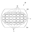
- FIG. 1 is a schematic plan view showing an example of the breaker plate 1 for an extruder according to the present embodiment.
- the breaker plate 1 has a hole 2 penetrating from one surface 1A to the other surface 1B.
- a plurality of holes 2 are provided via the boundary 3.
- the material of the breaker plate 1 is not particularly limited as long as it does not deform at a temperature at which the target resin composition can be melt-kneaded.
- SUS440C, SUS420J2, etc. are mentioned.
- the number of holes 2 depends on the type of resin to be granulated and the size of the extruder, but is preferably 2 to 40, preferably 4 to 30, more preferably 6 to 20.
- the aperture ratio of small holes is It is preferably set so as to have sufficient strength against the resin pressure received by the breaker plate calculated from the assumed molten resin pressure and the pressure receiving area of the breaker plate. If the aperture ratio of the hole 2 is reduced, sufficient strength can be easily obtained, and if the aperture ratio of the hole 2 is increased, the portion perpendicular to the flow direction in which the molten resin stays and adheres is reduced, and a sufficient discharge amount is easy. Is obtained.
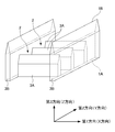
- FIG. 2 is a schematic diagram showing the relationship between the hole 2 and the boundary portion 3 in the region R of the breaker plate 1.
- the boundary part 3 (generic name for 3A and 3B) is tapered from one surface 1A to the other surface 1B.
- the tapered shape is not particularly limited as long as it is tapered from one surface 1A to the other surface 1B.
- the magnitude of the taper angle ⁇ is not particularly limited, but is preferably 30 degrees or more and 90 degrees or less, and more preferably 45 degrees or more and 70 degrees or less. If the taper angle ⁇ is too small, it may be damaged. When the taper angle ⁇ is too large, it is not possible to sufficiently obtain the resin composition retention suppressing effect, the operating time of the extruder elapses, and the resin composition is carbonized on the other surface 1B of the breaker plate 1, Solid carbides can accumulate. As solid carbide continues to accumulate, the carbide plugs the periphery of the hole 2. The carbide can be a foreign substance for the resin composition and can hinder the fluidity of the plasticized resin composition.
- an arbitrary one direction parallel to one surface 1A and the other surface 1B is defined as a first direction (X direction), which is parallel to one surface 1A and the other surface 1B, and is different from the first direction.
- first direction X direction
- second direction Y direction
- Z direction the direction from one surface 1A to the other surface 1B
- the first boundary 3A has the first direction as the longitudinal direction.
- the height is different from the height of the second boundary portion 3B having the second direction as the longitudinal direction.
- the first boundary portion 3A and the second boundary portion 3B are not particularly limited as long as they have different heights.
- the first boundary portion 3A may be higher than the second boundary portion 3B, and the second boundary portion 3B may be higher than the first boundary portion 3A.
- the higher boundary of height H Low boundary portion (H Low / H High) is 0.3 or more It is preferably 0.9 or less, and more preferably 0.5 or more and 0.8 or less.
- the shape of the hole 2 is not particularly limited.
- Examples of the shape of the hole 2 include a substantially square shape, a substantially hexagonal shape, and a substantially circular shape. Among them, the difference between the height of the first boundary portion 3A and the second boundary portion 3B is caused, and the flow of the resin composition in the flow direction of the resin composition in the flow path of the extruder tends to be disturbed,
- the shape of the hole 2 is preferably a substantially square shape.
- the shape of the hole 2 is a substantially rectangular shape or a substantially square shape, and it is more preferable that the first direction and the second direction are substantially vertical.
- the extruder of the present embodiment is the same as the conventionally known extruder 10 described in FIG. 4 except that the shape of the breaker plate is the breaker plate 1 described above.
- An extruder 10 shown in FIG. 4 includes a screw 40 uniaxially, biaxially or more, or a combination thereof, and a breaker plate 1.
- the breaker plate 1 is arranged such that one surface 1A is on the inlet side of the extruder 10 and the other surface 1B is on the outlet side of the extruder 10 in the flow path 30 on the outlet side of the tip 41 of the screw 40. Placed in.
- the rotational direction of the screw may be the same or opposite in each shaft, and may be meshed or non-meshed.
- shape of the shaft may be a parallel type or a conical type, and in addition, a tandem system in which screw extruders are combined in multiple stages may be used.
- the type of the polyacetal resin composition is not particularly limited, and the resin composition is formed at the inlet of the extruder 10 that is replaced with the breaker plate 1 of the present embodiment from the conventionally known breaker plate 50. It will not be specifically limited if a raw material is supplied and a resin composition is obtained from the exit of the extruder 10.
- FIG. 1 a raw material is supplied and a resin composition is obtained from the exit of the extruder 10.
- thermoplastic resin composition examples include a thermoplastic resin composition.
- the thermoplastic resin contained in the thermoplastic resin composition is not limited as long as it is a resin that is plasticized by application of shearing heat or heat, in addition to polyacetal (also referred to as polyoxymethylene, abbreviated as POM), Olefin resin, polyvinyl chloride, polyvinylidene chloride, acrylonitrile styrene copolymer, polystyrene, acrylic resin, methacrylic resin, polyamide, polycarbonate, polyvinyl alcohol, thermoplastic polyester, thermoplastic elastomer, polyphenylene sulfide, liquid crystal polymer, etc. Can be mentioned. These resins may be used alone or in combination of two or more.
- the extruder incorporating the breaker plate 1 of the present embodiment is particularly preferably used for granulation of a thermoplastic resin composition containing a thermoplastic polyurethane that easily adheres to a metal material as compared with a resin.
- a thermoplastic resin composition comprising a polyacetal resin, 1 to 60 parts by weight thermoplastic polyurethane with respect to the polyacetal resin, and 1 to 10 parts by weight polyisocyanate compound with respect to the polyacetal resin. It can be used suitably for the granulation of a thing.
- the breaker plate 1 has a plurality of holes 2 penetrating from one surface 1A toward the other surface 1B, and a boundary portion 3 separating adjacent holes 2 is directed from one surface 1A toward the other surface 1B. Tapered.
- the breaker plate 1 is disposed so that one surface 1A is on the inlet side and the other surface 1B is on the outlet side. And a raw material is supplied to the inlet 20 of the extruder 10, and the extruder 10 is operated.
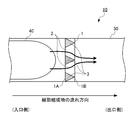
- the resin composition passing through the flow path 20 of the extruder 10 passes through the holes 2 of the breaker plate 1, the resin composition tapers according to the shape of the boundary portion 3 separating the adjacent holes 2 from the inlet side toward the outlet side. Form a stream. Therefore, it is possible to prevent the resin composition from staying on the back surface of the boundary portion 3.
- an arbitrary one direction parallel to one surface 1A (surface on the extruder inlet side) and the other surface 1B (surface on the extruder outlet side) of the breaker plate 1 is defined as a first direction (X direction), and the inlet side
- the other direction different from the first direction is the second direction (Y direction)
- the direction from the inlet side surface to the outlet side surface is the height direction (Z Direction)
- the height of the first boundary portion 3A having the first direction as the longitudinal direction is different from the height of the boundary portion having the second direction as the longitudinal direction. Therefore, when the resin composition passes through the hole 2 of the breaker plate 1, the flow of the resin composition can be disturbed on the back surface of the breaker plate 1, and as a result, the resin composition is agitated. Therefore, it is possible to further prevent the resin composition from staying on the back surface of the boundary portion 1.
- the breaker plate 1 for extruders which can suppress the residence of a resin composition still more less can be provided.
- Example 1 The breaker plate 1 described in the present embodiment (a 100-mesh screen is installed on the upstream side) was attached to the same-direction meshing twin-screw extruder (TEX30 manufactured by Nippon Steel Works).
- a polyacetal resin (polyacetal copolymer obtained by copolymerizing 96.7% by mass of trioxane and 3.3% by mass of 1,3-dioxolane, melt index (measured at 190 ° C., load 2160 g) ): 9 g / 10 min) 86.6% by weight, thermoplastic polyurethane (product name: milactolan P480 NAT, manufactured by Tosoh Corporation) 10% by weight, polyvalent isocyanate compound (product name: Bestanat T1890, manufactured by Degussa Japan) 1.0 weight %, And a polyacetal resin composition containing a hindered phenol-based antioxidant (Irganox 1010, manufactured by BASF).
- a hindered phenol-based antioxidant antioxidant
- the polyacetal resin composition discharged from the extruder was pelletized using a strand cutter.
- the throughput of the extruder was set to 10 kg / hr, the screw rotation speed was set to 130 rpm, and the temperature in the flow path was set to 200 ° C.
- Example 1 The same conditions as in Example 1 except that the breaker plate 1 has a conventionally known specification (the shape of the boundary portion is not tapered and the height of the first boundary portion and the second boundary portion is the same). A polyacetal resin composition was produced.
- the boundary portion has a tapered shape, but under the same conditions as in Example 1 except that a breaker plate having the same height of the first boundary portion and the second boundary portion is used.
- a polyacetal resin composition was produced.
- Example 1 As a result, the continuous operation time of Example 1 was 130 hours. On the other hand, the continuous operation time of Comparative Example 1 was 50 hours, and the continuous operation time of Comparative Example 2 was 100 hours.
Landscapes
- Engineering & Computer Science (AREA)
- Mechanical Engineering (AREA)
- Extrusion Moulding Of Plastics Or The Like (AREA)
- Processing And Handling Of Plastics And Other Materials For Molding In General (AREA)
- Compositions Of Macromolecular Compounds (AREA)
Abstract
樹脂組成物の滞留をよりいっそう少なく抑えることの可能な押出機用ブレーカープレートを提供する。 ブレーカープレート1は、一方の面1Aから他方の面1Bに向けて貫通する複数の孔2を有し、隣り合う孔2を隔てる境界部3は、一方の面1Aから他方の面1Bに向けてテーパー状であり、第1方向(X方向)を長手方向とする第1境界部3Aの高さ(Z方向の長さ)と、第2方向(Y方向)を長手方向とする第2境界部3Bの高さとが異なる。このブレーカープレート1は、押出機の入口に、ポリアセタール樹脂と、前記ポリアセタール樹脂に対して1重量部以上60重量部以下の熱可塑性ポリウレタンと、前記ポリアセタール樹脂に対して1重量部以上10重量部以下の多価イソシアネート化合物とを供給してスクリュー押出機の出口からポリアセタール樹脂組成物を得る用途に好適である。
Description
本発明は、押出機用ブレーカープレート、押出機及びポリアセタール樹脂組成物の製造方法に関する。
図4は、一般的な押出機10を示す一例である。押出機10は、樹脂原料を供給する入口20と、この樹脂原料が通過する流路30と、流路30の内部で樹脂原料を可塑化しながら押し出すスクリュー40と、スクリューの先端41よりも出口側の流路30において、可塑化された樹脂組成物に含まれる種々の異物を除去するため、上流側にスクリーン(図示せず)を設置したブレーカープレート50と、可塑化された樹脂組成物を排出する出口(図示せず)とを備える。
図5は、汎用されるブレーカープレート50の一例を示す模式図である。ブレーカープレート50は、一方の面50Aから他方の面50Bに向けて貫通する孔51を有する。孔51は、境界部52を介して複数設けられる。
しかしながら、図6に示すように、ブレーカープレート50の一方の面50Aが押出機10の入口20側に、他方の面50Bが出口側になるようにブレーカープレート50を配置し、樹脂原料を入口20に供給して押出機10を作動させると、ブレーカープレート50の他方の面50B、とりわけ、境界部52の背面において、樹脂組成物が滞留する。
図7は、押出機10を作動させてから所定時間が経過した後のブレーカープレート50の領域R’における他方の面50Bの状態を示す概略図である。境界部52の背面で樹脂組成物が滞留し続けると、時間の経過とともに、樹脂組成物が炭化し、固体の炭化物Cとなる。そして、固体の炭化物Cが蓄積され続けると、炭化物Cが孔51の周縁をふさぐ。炭化物Cは、樹脂組成物にとって異物となり得るほか、可塑化された樹脂組成物の流動性を妨げ得るため、好ましくない。
そこで、樹脂組成物の製造現場では、押出機10の出口から排出される樹脂組成物の色相を確認し、色相の変化が認められると、押出機10の運転を停止し、押出機10の内部を分解清掃している。しかしながら、分解清掃は、可動率低下、製品のコストアップにつながるため、分解清掃の頻度を最小限に抑えることが好ましい。
境界部52の背面での樹脂組成物の滞留を防ぐため、種々のブレーカープレートが提案されている。例えば、ブレーカープレートの端面近傍で、端面に向かって、各孔の径を徐々に増大させた拡孔部分を設けると共に、金属製円板の各同心円に沿って、断面形状V字状もしくはU字状の溝を設けてなり、しかも、同一円周上、隣り合う拡孔部分と拡孔部分との溝の底における隙間、及び隣り合う溝と溝との端面における隙間をそれぞれ2ミリ以下にすることが提案されている(特許文献1参照)。
また、板状体の両面の中央部に先細りの突起を設け、この突起の周囲の板状体に複数個の貫通孔を設けることが提案されている(特許文献2参照)。
また、材料を通過させる穴を入口から出口へかけて外周側へ放射状に傾斜させ、出口側の中心部に突起を設けることが提案されている(特許文献3参照)。
また、ブレーカープレートの中心部に近い方に設けた孔部に比べ、ブレーカープレートの外縁部に近い方に設けた孔部を大径となるように配列することが提案されている(特許文献4参照)。
また、ブレーカープレートの外周部に小孔が存在し、かつ、ブレーカープレートの押出機における下流側の面の中央部に突起状物を有することが提案されている(特許文献5参照)。
しかしながら、対象となる樹脂がエンジニアリングプラスチックス等の高融点で成形温度が高い熱可塑性樹脂である場合、ブレーカープレートの背面に滞留した樹脂の炭化が短時間で進むことから、滞留防止のためのさらなる改良が求められる。
ところで、高靱性であることを目的として、熱可塑性ポリウレタンを含有するポリアセタール樹脂組成物を提供することが求められている。しかしながら、熱可塑性ポリウレタンの極性は、ポリアセタール樹脂の極性よりも高いことから、熱可塑性ポリウレタンは、ポリアセタール樹脂に比べ、金属材料に張り付き易く、押出機の作動時間が経過するにつれて、ブレーカープレートの背面で選択的に炭化するという性質を有する。このことから、対処となる熱可塑性樹脂組成物が、熱可塑性ポリウレタンを含有するポリアセタール樹脂組成物である場合、滞留防止のためのなおいっそうの改良が求められる。
本発明は、樹脂組成物の滞留をよりいっそう少なく抑えることの可能な押出機用ブレーカープレートを提供することを目的とする。
本発明者は、上記課題を達成すべく鋭意検討した結果、隣り合う孔を隔てる境界部をテーパー状にし、かつ、一方の面及び他方の面に平行な任意の一方向である第1方向を長手方向とする境界部の高さと、上記一方の面及び上記他方の面に平行であり、上記第1方向とは異なる他の一方向である第2方向を長手方向とする境界部の高さとを異ならせることで、上記目的を達成し得ることを見出し、本発明を完成するに至った。より具体的に、本発明は以下のものを提供する。
(1)本発明は、一方の面から他方の面に向けて貫通する複数の孔を有し、隣り合う孔を隔てる境界部は、前記一方の面から前記他方の面に向けてテーパー状であり、前記一方の面及び前記他方の面に平行な任意の一方向を第1方向とし、前記一方の面及び前記他方の面に平行であり、前記第1方向とは異なる他の一方向を第2方向とし、前記一方の面から前記他方の面への方向を高さ方向とするとき、前記第1方向を長手方向とする前記境界部の高さと、前記第2方向を長手方向とする前記境界部の高さとが異なる、押出機用ブレーカープレートである。
(2)また、本発明は、前記孔の形状が略四角形状である、(1)に記載の押出機用分ブレーカープレートである。
(3)また、本発明は、前記略四角形状が略矩形状又は略正方形状であり、前記第1方向と前記第2方向とが略垂直である、(2)に記載の押出機用ブレーカープレートである。
(4)また、本発明は、スクリューと、(1)から(3)のいずれかに記載の押出機用ブレーカープレートとを備え、前記押出機用ブレーカープレートは、前記スクリューの先端よりも出口側の流路において、前記一方の面が入口側に、前記他方の面が出口側になるように配置される、押出機である。
(5)また、本発明は、(4)に記載の押出機の入口に、ポリアセタール樹脂と、前記ポリアセタール樹脂に対して1重量部以上60重量部以下の熱可塑性ポリウレタンと、前記ポリアセタール樹脂に対して1重量部以上10重量部以下の多価イソシアネート化合物とを供給して前記スクリュー押出機の出口からポリアセタール樹脂組成物を得る、ポリアセタール樹脂組成物の製造方法である。
本発明に係る押出機用ブレーカープレートは、一方の面から他方の面に向けて貫通する複数の孔を有し、隣り合う孔を隔てる境界部は、上記一方の面から上記他方の面に向けてテーパー状である。この押出機用ブレーカープレートを、押出機におけるスクリューの先端よりも出口側の流路において、上記一方の面が入口側に、上記他方の面が出口側になるように配置する。そして、押出機の入口に原料を供給し、押出機を作動させる。押出機の流路を通過する樹脂組成物は、ブレーカープレートの孔を通過する際、入口側から出口側に向けて、隣り合う孔を隔てる境界部の形状であるテーパー状の流れを形成する。そのため、境界部の背面で樹脂組成物が滞留するのを防止できる。
また、ブレーカープレートの一方の面(押出機入口側の面)及び他方の面(押出機出口側の面)に平行な任意の一方向を第1方向とし、入口側の面及び出口側の面に平行であり、第1方向とは異なる他の一方向を第2方向とし、入口側の面から出口側の面への方向を高さ方向とするとき、第1方向を長手方向とする境界部の高さと、第2方向を長手方向とする境界部の高さとが異なる。そのため、樹脂組成物がブレーカープレートの孔を通過する際、ブレーカープレートの背面で樹脂組成物の流れに乱れをつくることができ、結果として、樹脂組成物が撹拌する。そのため、境界部の背面で樹脂組成物が滞留するのをよりいっそう防止できる。
したがって、本発明によると、樹脂組成物の滞留をよりいっそう少なく抑えることの可能な押出機用ブレーカープレートを提供できる。
以下、本発明の具体的な実施形態について、詳細に説明するが、本発明は、以下の実施形態に何ら限定されるものではなく、本発明の目的の範囲内において、適宜変更を加えて実施することができる。
<押出機用ブレーカープレート>
図1は、本実施形態の押出機用ブレーカープレート1の一例を示す概略平面図である。ブレーカープレート1は、一方の面1Aから他方の面1Bに向けて貫通する孔2を有する。孔2は、境界部3を介して複数設けられる。
図1は、本実施形態の押出機用ブレーカープレート1の一例を示す概略平面図である。ブレーカープレート1は、一方の面1Aから他方の面1Bに向けて貫通する孔2を有する。孔2は、境界部3を介して複数設けられる。
ブレーカープレート1の材質は、対象となる樹脂組成物を溶融混練可能な温度で変形しないものであれば、特に限定されない。例えば、SUS440C、SUS420J2等が挙げられる。
孔2の数は、造粒する樹脂の種類や押出機の大きさにもよるが、2~40個、好ましくは4~30個、さらに6~20個が好ましく、また小孔の開口率は想定される溶融樹脂圧とブレーカープレートの受圧面積から計算されるブレーカープレートが受ける樹脂圧力に対して十分な強度を有するように設定されることが好ましい。孔2の開口率を小さくすると、容易に十分な強度が得られ、また孔2の開口率を大きくすると溶融樹脂が滞留付着する流動方向に対して垂直な部分が少なくなり十分な吐出量が容易に得られる。
図2は、ブレーカープレート1の領域Rにおける孔2と境界部3との関係を示す模式図である。境界部3(3A,3Bの総称)は、一方の面1Aから他方の面1Bに向けてテーパー状である。
テーパー状の態様は、一方の面1Aから他方の面1Bに向けて先細りの態様になっていれば特に限定されない。テーパー角θの大きさも特に限定されないが、30度以上90度以下であることが好ましく、45度以上70度以下であることがより好ましい。テーパー角θが小さすぎると、破損する可能性がある。テーパー角θが大きすぎると、樹脂組成物の滞留抑制効果を十分に得ることができず、押出機の作動時間が経過するとともに、ブレーカープレート1の他方の面1Bで樹脂組成物が炭化し、固体の炭化物が蓄積し得る。固体の炭化物が蓄積され続けると、炭化物が孔2の周縁をふさぐ。炭化物は、樹脂組成物にとって異物となり得るほか、可塑化された樹脂組成物の流動性を妨げ得る。
また、一方の面1A及び他方の面1Bに平行な任意の一方向を第1方向(X方向)とし、一方の面1A及び他方の面1Bに平行であり、第1方向とは異なる他の一方向を第2方向(Y方向)とし、一方の面1Aから他方の面1Bへの方向を高さ方向(Z方向)とするとき、第1方向を長手方向とする第1境界部3Aの高さと、第2方向を長手方向とする第2境界部3Bの高さとが異なる。第1境界部3A及び第2境界部3Bの高さが異なることで、樹脂組成物がブレーカープレート1の孔2を通過する際、押出機の流路における樹脂組成物の進行方向出口側で樹脂組成物の流れに乱れをつくることができ、結果として、樹脂組成物が撹拌する。そのため、境界部の背面で樹脂組成物が滞留するのをよりいっそう防止できる。
第1境界部3A及び第2境界部3Bは、高さが互いに異なっていれば特に限定されない。第1境界部3Aが第2境界部3Bに比べて高くてもよいし、第2境界部3Bが第1境界部3Aに比べて高くてもよい。
第1境界部3A及び第2境界部3Bのうち、低い方の境界部の高さHLowの高い方の境界部の高さHHighに対する比(HLow/HHigh)は、0.3以上0.9以下であることが好ましく、0.5以上0.8以下であることがより好ましい。HLow/HHighが小さすぎると、第1境界部3A及び第2境界部3Bのうち、低い方の境界部が、可塑化された樹脂組成物に含まれる種々の異物を除去するというブレーカープレート1本来の機能を発揮できない可能性がある。HLow/HHighが大きすぎると、押出機の流路における樹脂組成物の進行方向出口側で樹脂組成物の流れに乱れをつくることができず、境界部の背面で樹脂組成物が滞留することに起因して、押出機の作動時間が経過するとともに、ブレーカープレート1の他方の面1Bで樹脂組成物が炭化し、固体の炭化物が蓄積し得る。
孔2の形状は特に限定されるものでない。孔2の形状として、略四角形状、略六角形状、略円形状等が挙げられる。中でも、第1境界部3A及び第2境界部3Bの高さに違いを生じさせ、押出機の流路における樹脂組成物の進行方向出口側で樹脂組成物の流れに乱れをつくり易い点で、孔2の形状は、略四角形状であることが好ましい。また、孔2の形状は、略矩形状又は略正方形状であり、第1方向と第2方向とが略垂直であることがより好ましい。
<押出機>
本実施形態の押出機は、ブレーカープレートの形状が上記したブレーカープレート1であること以外は、図4で説明した従来公知の押出機10と同じである。図4に示す押出機10は、一軸、二軸以上或いはこれらを組み合わせたスクリュー40と、ブレーカープレート1とを備える。その際、ブレーカープレート1は、スクリュー40の先端41よりも出口側の流路30において、一方の面1Aが押出機10の入口側に、他方の面1Bが押出機10の出口側になるように配置される。
本実施形態の押出機は、ブレーカープレートの形状が上記したブレーカープレート1であること以外は、図4で説明した従来公知の押出機10と同じである。図4に示す押出機10は、一軸、二軸以上或いはこれらを組み合わせたスクリュー40と、ブレーカープレート1とを備える。その際、ブレーカープレート1は、スクリュー40の先端41よりも出口側の流路30において、一方の面1Aが押出機10の入口側に、他方の面1Bが押出機10の出口側になるように配置される。
二軸の場合、スクリューの回転方向がそれぞれの軸で反対でも同じでもよく、また、噛み合い型でも非噛み合い型でもよい。また、軸の形状は、パラレルタイプでもコニカルタイプでもよく、加えて、スクリュー押出機を多段に組合わせたタンデム方式でもよい。
<ポリアセタール樹脂組成物の製造方法>
本実施形態において、ポリアセタール樹脂組成物の種類は特に限定されるものでなく、従来公知のブレーカープレート50から本実施形態のブレーカープレート1に置き換えた押出機10の入口に、樹脂組成物を構成する原料を供給し、押出機10の出口から樹脂組成物を得るものであれば特に限定されない。
本実施形態において、ポリアセタール樹脂組成物の種類は特に限定されるものでなく、従来公知のブレーカープレート50から本実施形態のブレーカープレート1に置き換えた押出機10の入口に、樹脂組成物を構成する原料を供給し、押出機10の出口から樹脂組成物を得るものであれば特に限定されない。
押出機10に供給される樹脂組成物として、熱可塑性樹脂組成物が挙げられる。熱可塑性樹脂組成物に含まれる熱可塑性樹脂は、剪断発熱や熱を加えることによって可塑化する樹脂であれば限定されず、ポリアセタール(ポリオキシメチレンとも称され、POMと略される)のほか、オレフィン系樹脂、ポリ塩化ビニル、ポリ塩化ビニリデン、アクリロニトリルスチレン共重合体、ポリスチレン、アクリル系樹脂、メタクリル系樹脂、ポリアミド、ポリカーボネート、ポリビニルアルコール、熱可塑性ポリエステル、熱可塑性エラストマー、ポリフェニレンサルファイド、液晶ポリマー等が挙げられる。これらの樹脂は単独でも2種類以上を併用してもよい。
これらの中で、本実施形態のブレーカープレート1を組み込んだ押出機は、特に、樹脂に比べて金属材料に張り付き易い熱可塑性ポリウレタンを含有する熱可塑性樹脂組成物の造粒に好適に使用することができる。例えば、ポリアセタール樹脂と、ポリアセタール樹脂に対して1重量部以上60重量部以下の熱可塑性ポリウレタンと、ポリアセタール樹脂に対して1重量部以上10重量部以下の多価イソシアネート化合物とを含む熱可塑性樹脂組成物の造粒に好適に使用することができる。
<本実施形態の作用>
以下、図3を参照しながら本実施形態の作用について説明する。ブレーカープレート1は、一方の面1Aから他方の面1Bに向けて貫通する複数の孔2を有し、隣り合う孔2を隔てる境界部3は、一方の面1Aから他方の面1Bに向けてテーパー状である。ブレーカープレート1を、押出機10におけるスクリュー40の先端41よりも出口側の流路30において、一方の面1Aが入口側に、他方の面1Bが出口側になるように配置する。そして、押出機10の入口20に原料を供給し、押出機10を作動させる。押出機10の流路20を通過する樹脂組成物は、ブレーカープレート1の孔2を通過する際、入口側から出口側に向けて、隣り合う孔2を隔てる境界部3の形状にしたがい、テーパー状の流れを形成する。そのため、境界部3の背面で樹脂組成物が滞留するのを防止できる。
以下、図3を参照しながら本実施形態の作用について説明する。ブレーカープレート1は、一方の面1Aから他方の面1Bに向けて貫通する複数の孔2を有し、隣り合う孔2を隔てる境界部3は、一方の面1Aから他方の面1Bに向けてテーパー状である。ブレーカープレート1を、押出機10におけるスクリュー40の先端41よりも出口側の流路30において、一方の面1Aが入口側に、他方の面1Bが出口側になるように配置する。そして、押出機10の入口20に原料を供給し、押出機10を作動させる。押出機10の流路20を通過する樹脂組成物は、ブレーカープレート1の孔2を通過する際、入口側から出口側に向けて、隣り合う孔2を隔てる境界部3の形状にしたがい、テーパー状の流れを形成する。そのため、境界部3の背面で樹脂組成物が滞留するのを防止できる。
また、ブレーカープレート1の一方の面1A(押出機入口側の面)及び他方の面1B(押出機出口側の面)に平行な任意の一方向を第1方向(X方向)とし、入口側の面及び出口側の面に平行であり、第1方向とは異なる他の一方向を第2方向(Y方向)とし、入口側の面から出口側の面への方向を高さ方向(Z方向)とするとき、第1方向を長手方向とする第1境界部3Aの高さと、第2方向を長手方向とする境界部の高さとが異なる。そのため、樹脂組成物がブレーカープレート1の孔2を通過する際、ブレーカープレート1の背面で樹脂組成物の流れに乱れをつくることができ、結果として、樹脂組成物が撹拌する。そのため、境界部1の背面で樹脂組成物が滞留するのをよりいっそう防止できる。
<本実施形態の効果>
したがって、本実施形態によると、樹脂組成物の滞留をよりいっそう少なく抑えることの可能な押出機用ブレーカープレート1を提供できる。
したがって、本実施形態によると、樹脂組成物の滞留をよりいっそう少なく抑えることの可能な押出機用ブレーカープレート1を提供できる。
以下、実施例により本発明を具体的に説明するが、本発明はこれらに限定されるものではない。
<実施例及び比較例>
〔実施例1〕
同方向噛み合い型二軸押出機(日本製鋼所社製TEX30)に本実施形態で説明したブレーカープレート1(上流側に100メッシュのスクリーンを設置)を取り付けた。この押出機を使用して、ポリアセタール樹脂(トリオキサン96.7質量%と1,3-ジオキソラン3.3質量%とを共重合させてなるポリアセタール共重合体,メルトインデックス(190℃,荷重2160gで測定):9g/10min)86.6重量%、熱可塑性ポリウレタン(製品名:ミラクトランP480NAT,東ソー社製)10重量%、多価イソシアネート化合物(製品名:ベスタナートT1890,デグサジャパン社製)1.0重量%、及びヒンダードフェノール系酸化防止剤(イルガノックス1010,BASF社製)を含有するポリアセタール樹脂組成物を製造した。押出機から排出されたポリアセタール樹脂組成物に対し、ストランドカッターを用いてペレット化した。押出機の処理量を10kg/hr、スクリュー回転数を130rpm、流路内の温度を200℃に設定した。
〔実施例1〕
同方向噛み合い型二軸押出機(日本製鋼所社製TEX30)に本実施形態で説明したブレーカープレート1(上流側に100メッシュのスクリーンを設置)を取り付けた。この押出機を使用して、ポリアセタール樹脂(トリオキサン96.7質量%と1,3-ジオキソラン3.3質量%とを共重合させてなるポリアセタール共重合体,メルトインデックス(190℃,荷重2160gで測定):9g/10min)86.6重量%、熱可塑性ポリウレタン(製品名:ミラクトランP480NAT,東ソー社製)10重量%、多価イソシアネート化合物(製品名:ベスタナートT1890,デグサジャパン社製)1.0重量%、及びヒンダードフェノール系酸化防止剤(イルガノックス1010,BASF社製)を含有するポリアセタール樹脂組成物を製造した。押出機から排出されたポリアセタール樹脂組成物に対し、ストランドカッターを用いてペレット化した。押出機の処理量を10kg/hr、スクリュー回転数を130rpm、流路内の温度を200℃に設定した。
〔比較例1〕
ブレーカープレート1が従来公知の仕様(境界部の形状がテーパー状でなく、第1境界部及び第2境界部の高さが同じであるブレーカープレート)であること以外は、実施例1と同じ条件でポリアセタール樹脂組成物を製造した。
ブレーカープレート1が従来公知の仕様(境界部の形状がテーパー状でなく、第1境界部及び第2境界部の高さが同じであるブレーカープレート)であること以外は、実施例1と同じ条件でポリアセタール樹脂組成物を製造した。
〔比較例2〕
ブレーカープレート1の代わりに、境界部の形状がテーパー状であるものの、第1境界部及び第2境界部の高さが同じであるブレーカープレートを使用したこと以外は、実施例1と同じ条件でポリアセタール樹脂組成物を製造した。
ブレーカープレート1の代わりに、境界部の形状がテーパー状であるものの、第1境界部及び第2境界部の高さが同じであるブレーカープレートを使用したこと以外は、実施例1と同じ条件でポリアセタール樹脂組成物を製造した。
<評価>
二軸押出機の運転開始から10分毎に、ポリアセタール樹脂組成物の色相を目視で確認した。そして、二軸押出機の運転開始から炭化物の存在がはじめて認められるまでの時間を二軸押出機の連続可能運転時間とした。
二軸押出機の運転開始から10分毎に、ポリアセタール樹脂組成物の色相を目視で確認した。そして、二軸押出機の運転開始から炭化物の存在がはじめて認められるまでの時間を二軸押出機の連続可能運転時間とした。
その結果、実施例1の連続可能運転時間は、130時間であった。一方、比較例1の連続可能運転時間は、50時間であり、比較例2の連続可能運転時間は、100時間であった。
この結果から、本実施形態で説明した形状のブレーカープレート1を用いると、樹脂組成物の滞留をよりいっそう少なく抑えることができる。その結果、押出機の内部を分解清掃する頻度を最小限に抑えることができ、経済性に優れる。
1 押出機用ブレーカープレート
1A 一方の面
1B 他方の面
2 孔
3 境界部
3A 第1境界部
3B 第2境界部
1A 一方の面
1B 他方の面
2 孔
3 境界部
3A 第1境界部
3B 第2境界部
Claims (5)
- 一方の面から他方の面に向けて貫通する複数の孔を有し、
隣り合う孔を隔てる境界部は、前記一方の面から前記他方の面に向けてテーパー状であり、
前記一方の面及び前記他方の面に平行な任意の一方向を第1方向とし、前記一方の面及び前記他方の面に平行であり、前記第1方向とは異なる他の一方向を第2方向とし、前記一方の面から前記他方の面への方向を高さ方向とするとき、前記第1方向を長手方向とする前記境界部の高さと、前記第2方向を長手方向とする前記境界部の高さとが異なる、押出機用ブレーカープレート。 - 前記孔の形状が略四角形状である、請求項1に記載の押出機用分ブレーカープレート。
- 前記略四角形状が略矩形状又は略正方形状であり、
前記第1方向と前記第2方向とが略垂直である、請求項2に記載の押出機用ブレーカープレート。 - スクリューと、
請求項1から3のいずれかに記載の押出機用ブレーカープレートとを備え、
前記押出機用ブレーカープレートは、前記スクリューの先端よりも出口側の流路において、前記一方の面が入口側に、前記他方の面が出口側になるように配置される、押出機。 - 請求項4に記載の押出機の入口に、ポリアセタール樹脂と、前記ポリアセタール樹脂に対して1重量部以上60重量部以下の熱可塑性ポリウレタンと、前記ポリアセタール樹脂に対して1重量部以上10重量部以下の多価イソシアネート化合物とを供給して前記スクリュー押出機の出口からポリアセタール樹脂組成物を得る、ポリアセタール樹脂組成物の製造方法。
Priority Applications (1)
| Application Number | Priority Date | Filing Date | Title |
|---|---|---|---|
| MYPI2018702138A MY187350A (en) | 2015-12-22 | 2016-11-04 | Extruder breaker-plate, extruder and method of manufacturing polyacetal resin composition |
Applications Claiming Priority (2)
| Application Number | Priority Date | Filing Date | Title |
|---|---|---|---|
| JP2015249651A JP6180498B2 (ja) | 2015-12-22 | 2015-12-22 | 押出機用ブレーカープレート、押出機及びポリアセタール樹脂組成物の製造方法 |
| JP2015-249651 | 2015-12-22 |
Publications (1)
| Publication Number | Publication Date |
|---|---|
| WO2017110264A1 true WO2017110264A1 (ja) | 2017-06-29 |
Family
ID=59089310
Family Applications (1)
| Application Number | Title | Priority Date | Filing Date |
|---|---|---|---|
| PCT/JP2016/082825 Ceased WO2017110264A1 (ja) | 2015-12-22 | 2016-11-04 | 押出機用ブレーカープレート、押出機及びポリアセタール樹脂組成物の製造方法 |
Country Status (3)
| Country | Link |
|---|---|
| JP (1) | JP6180498B2 (ja) |
| MY (1) | MY187350A (ja) |
| WO (1) | WO2017110264A1 (ja) |
Citations (11)
| Publication number | Priority date | Publication date | Assignee | Title |
|---|---|---|---|---|
| JPS5023368U (ja) * | 1973-06-27 | 1975-03-15 | ||
| JPS5247563U (ja) * | 1975-09-30 | 1977-04-04 | ||
| JPS54108864A (en) * | 1978-02-15 | 1979-08-25 | Matsushita Electric Works Ltd | Breaker plate assembly of extrusion molding machine |
| JPS54163958A (en) * | 1978-06-15 | 1979-12-27 | Matsushita Electric Works Ltd | Synthetic resin extruding apparatus |
| JPH0388722U (ja) * | 1989-11-24 | 1991-09-10 | ||
| JPH0415522U (ja) * | 1990-05-31 | 1992-02-07 | ||
| JPH04276420A (ja) * | 1991-03-04 | 1992-10-01 | Sekisui Chem Co Ltd | 押出成形機の混練押出機構 |
| JPH0717532U (ja) * | 1993-08-31 | 1995-03-28 | 株式会社ムサシノキカイ | ダイゲートのブレーカープレート |
| JPH0857937A (ja) * | 1994-08-25 | 1996-03-05 | Hitachi Cable Ltd | クロスヘッド |
| JP2006205418A (ja) * | 2005-01-26 | 2006-08-10 | Nok Corp | 押出機及びブレーカプレート |
| JP2014233945A (ja) * | 2013-06-05 | 2014-12-15 | 住友電装株式会社 | ブレーカープレート及び押出装置 |
Family Cites Families (1)
| Publication number | Priority date | Publication date | Assignee | Title |
|---|---|---|---|---|
| JP2010064456A (ja) * | 2008-09-12 | 2010-03-25 | Mitsubishi Gas Chemical Co Inc | ポリアセタール樹脂成形体の製造方法 |
-
2015
- 2015-12-22 JP JP2015249651A patent/JP6180498B2/ja active Active
-
2016
- 2016-11-04 MY MYPI2018702138A patent/MY187350A/en unknown
- 2016-11-04 WO PCT/JP2016/082825 patent/WO2017110264A1/ja not_active Ceased
Patent Citations (11)
| Publication number | Priority date | Publication date | Assignee | Title |
|---|---|---|---|---|
| JPS5023368U (ja) * | 1973-06-27 | 1975-03-15 | ||
| JPS5247563U (ja) * | 1975-09-30 | 1977-04-04 | ||
| JPS54108864A (en) * | 1978-02-15 | 1979-08-25 | Matsushita Electric Works Ltd | Breaker plate assembly of extrusion molding machine |
| JPS54163958A (en) * | 1978-06-15 | 1979-12-27 | Matsushita Electric Works Ltd | Synthetic resin extruding apparatus |
| JPH0388722U (ja) * | 1989-11-24 | 1991-09-10 | ||
| JPH0415522U (ja) * | 1990-05-31 | 1992-02-07 | ||
| JPH04276420A (ja) * | 1991-03-04 | 1992-10-01 | Sekisui Chem Co Ltd | 押出成形機の混練押出機構 |
| JPH0717532U (ja) * | 1993-08-31 | 1995-03-28 | 株式会社ムサシノキカイ | ダイゲートのブレーカープレート |
| JPH0857937A (ja) * | 1994-08-25 | 1996-03-05 | Hitachi Cable Ltd | クロスヘッド |
| JP2006205418A (ja) * | 2005-01-26 | 2006-08-10 | Nok Corp | 押出機及びブレーカプレート |
| JP2014233945A (ja) * | 2013-06-05 | 2014-12-15 | 住友電装株式会社 | ブレーカープレート及び押出装置 |
Also Published As
| Publication number | Publication date |
|---|---|
| JP6180498B2 (ja) | 2017-08-16 |
| JP2017113926A (ja) | 2017-06-29 |
| MY187350A (en) | 2021-09-22 |
Similar Documents
| Publication | Publication Date | Title |
|---|---|---|
| JP5369614B2 (ja) | 粉体原料用押出機および熱可塑性樹脂組成物の製造方法 | |
| EP2254743B1 (de) | Entgasungsextruder zum extrudieren von formmassen | |
| JP2011079306A (ja) | 熱可塑性樹脂組成物の押出成形方法 | |
| JP6180498B2 (ja) | 押出機用ブレーカープレート、押出機及びポリアセタール樹脂組成物の製造方法 | |
| EP3389984B1 (en) | Device and process for processing polyolefin polymers | |
| JP5774901B2 (ja) | 樹脂押出用ダイ | |
| JP5410696B2 (ja) | 押出機スクリュー及びポリメチルペンテンフィルムの製造方法 | |
| JP6494689B2 (ja) | 繊維強化熱可塑性樹脂押出物の製造方法および製造装置 | |
| JP5872905B2 (ja) | 透明熱可塑性樹脂ペレットの製造方法 | |
| US9796115B1 (en) | Extruder screw | |
| JP5728077B2 (ja) | 熱可塑性樹脂組成物ペレットの製造方法、押出機及びダイプレート | |
| CN107000295B (zh) | 用于减少凝胶的结构元件以及凝胶减少装置和方法 | |
| JP3717485B2 (ja) | 樹脂ペレット製造用ダイ及び該ダイを用いた樹脂ペレットの製造方法 | |
| JP2018127735A5 (ja) | 交絡長繊維集合体、樹脂ペレット及びその製造方法 | |
| KR100536128B1 (ko) | 수지재의 유동성 향상을 위한 압출기의 브레이커 플레이트 | |
| JP2018161860A (ja) | 熱可塑性樹脂組成物のペレットの製造方法 | |
| CN220146633U (zh) | 一种防目脂挤出机机头模具 | |
| JP4321329B2 (ja) | 樹脂成形用ダイ及び樹脂成形品の製造方法 | |
| EP3389985B1 (en) | Device and related method for processing polymers | |
| CN218857653U (zh) | 一种橡胶复合助剂造粒除杂装置 | |
| JP5522995B2 (ja) | 高分子組成物の混練装置及び混練方法 | |
| JP6943711B2 (ja) | 押出機用ダイ、押出機、及び樹脂組成物の製造方法 | |
| JP2024037315A (ja) | 熱可塑性樹脂組成物の成形品の成形機、および成形品を製造する方法 | |
| WO2023203914A1 (ja) | ガラス繊維強化ポリエステル系樹脂組成物の製造方法 | |
| CN117651637A (zh) | 利用聚晶金刚石元件的聚合物挤出装置和方法 |
Legal Events
| Date | Code | Title | Description |
|---|---|---|---|
| 121 | Ep: the epo has been informed by wipo that ep was designated in this application |
Ref document number: 16878162 Country of ref document: EP Kind code of ref document: A1 |
|
| NENP | Non-entry into the national phase |
Ref country code: DE |
|
| 122 | Ep: pct application non-entry in european phase |
Ref document number: 16878162 Country of ref document: EP Kind code of ref document: A1 |