WO2017110228A1 - 流量調整機構および流体継手 - Google Patents
流量調整機構および流体継手 Download PDFInfo
- Publication number
- WO2017110228A1 WO2017110228A1 PCT/JP2016/081305 JP2016081305W WO2017110228A1 WO 2017110228 A1 WO2017110228 A1 WO 2017110228A1 JP 2016081305 W JP2016081305 W JP 2016081305W WO 2017110228 A1 WO2017110228 A1 WO 2017110228A1
- Authority
- WO
- WIPO (PCT)
- Prior art keywords
- working fluid
- flow rate
- cam
- fluid
- valve stem
- Prior art date
- Legal status (The legal status is an assumption and is not a legal conclusion. Google has not performed a legal analysis and makes no representation as to the accuracy of the status listed.)
- Ceased
Links
Images


Classifications
-
- F—MECHANICAL ENGINEERING; LIGHTING; HEATING; WEAPONS; BLASTING
- F16—ENGINEERING ELEMENTS AND UNITS; GENERAL MEASURES FOR PRODUCING AND MAINTAINING EFFECTIVE FUNCTIONING OF MACHINES OR INSTALLATIONS; THERMAL INSULATION IN GENERAL
- F16D—COUPLINGS FOR TRANSMITTING ROTATION; CLUTCHES; BRAKES
- F16D33/00—Rotary fluid couplings or clutches of the hydrokinetic type
- F16D33/06—Rotary fluid couplings or clutches of the hydrokinetic type controlled by changing the amount of liquid in the working circuit
- F16D33/08—Rotary fluid couplings or clutches of the hydrokinetic type controlled by changing the amount of liquid in the working circuit by devices incorporated in the fluid coupling, with or without remote control
- F16D33/10—Rotary fluid couplings or clutches of the hydrokinetic type controlled by changing the amount of liquid in the working circuit by devices incorporated in the fluid coupling, with or without remote control consisting of controllable supply and discharge openings
-
- F—MECHANICAL ENGINEERING; LIGHTING; HEATING; WEAPONS; BLASTING
- F16—ENGINEERING ELEMENTS AND UNITS; GENERAL MEASURES FOR PRODUCING AND MAINTAINING EFFECTIVE FUNCTIONING OF MACHINES OR INSTALLATIONS; THERMAL INSULATION IN GENERAL
- F16D—COUPLINGS FOR TRANSMITTING ROTATION; CLUTCHES; BRAKES
- F16D33/00—Rotary fluid couplings or clutches of the hydrokinetic type
- F16D33/06—Rotary fluid couplings or clutches of the hydrokinetic type controlled by changing the amount of liquid in the working circuit
- F16D33/08—Rotary fluid couplings or clutches of the hydrokinetic type controlled by changing the amount of liquid in the working circuit by devices incorporated in the fluid coupling, with or without remote control
- F16D33/14—Rotary fluid couplings or clutches of the hydrokinetic type controlled by changing the amount of liquid in the working circuit by devices incorporated in the fluid coupling, with or without remote control consisting of shiftable or adjustable scoops
-
- F—MECHANICAL ENGINEERING; LIGHTING; HEATING; WEAPONS; BLASTING
- F16—ENGINEERING ELEMENTS AND UNITS; GENERAL MEASURES FOR PRODUCING AND MAINTAINING EFFECTIVE FUNCTIONING OF MACHINES OR INSTALLATIONS; THERMAL INSULATION IN GENERAL
- F16H—GEARING
- F16H41/00—Rotary fluid gearing of the hydrokinetic type
- F16H41/24—Details
Definitions
- the present invention relates to a flow rate adjusting mechanism that adjusts the flow rate of a working fluid in a fluid coupling. Moreover, this invention relates to the fluid coupling provided with such a flow volume adjustment mechanism.
- the fluid coupling is a device that transmits the rotation of the input shaft to the output shaft via the working fluid that exists between the impeller that is the input-side impeller and the runner that is the output-side impeller.
- the working fluid For example, hydraulic oil is used as the working fluid.
- the fluid coupling includes a scoop tube (rake pipe) for increasing or decreasing the amount of working fluid in the fluid chamber formed between the impeller and the runner.
- the amount of working fluid in the fluid chamber varies depending on the position of the scoop tube. By moving the scoop tube, the amount of working fluid, that is, the rotational speed of the output shaft can be changed.
- the fluid coupling further includes a fluid cooling device for cooling the working fluid, and a working fluid circulation line extending through the fluid cooling device.
- the inlet of the working fluid circulation line is connected to the scoop tube, and the outlet of the working fluid circulation line communicates with the fluid chamber.
- the working fluid discharged through the scoop tube flows through the working fluid circulation line and is cooled by the fluid cooling device, and then returns to the fluid chamber through the working fluid circulation line. In this way, the working fluid circulates between the fluid chamber and the fluid cooling device.
- the fluid coupling is a device that can change the rotation speed of the output shaft steplessly from low speed to high speed by moving the scoop tube, but it is known that slip loss occurs between the impeller and the runner. It has been.
- the slip loss becomes the largest and the calorific value of the working fluid also increases. growing. For this reason, it is necessary to increase the flow rate of the working fluid flowing through the working fluid circulation line to suppress the temperature rise of the working fluid in the fluid chamber.
- the slip loss is small, so that the stirring loss of the working fluid is reduced and the efficiency is improved.
- the flow rate of the working fluid is preferably small.
- the present invention has been made in view of the above-described circumstances, and an object thereof is to provide a flow rate adjustment mechanism that can easily adjust the flow rate of a working fluid with a simple structure. Moreover, an object of this invention is to provide the fluid coupling provided with such a flow volume adjustment mechanism.
- one aspect of the present invention is a flow rate adjusting mechanism for adjusting the flow rate of a working fluid in a fluid coupling, the housing having a flow path communicating with a working fluid circulation line, and the flow path.
- a valve body movably accommodated therein, a cam movable with a scoop tube for adjusting the amount of the working fluid in a fluid chamber formed between the impeller and the runner, and one end of the cam
- a valve rod contacting the cam and having the other end connected to the valve body is provided.
- the one end of the valve stem is composed of a cam follower that is in rolling contact with the cam.
- the cam is composed of a concave curved surface.
- a preferred embodiment of the present invention further includes a valve stem guide that supports the valve stem so that the valve stem can move in an axial direction thereof, and the valve stem guide and the valve stem close an open end of the flow path. And the pressure equalizing hole is formed in the said valve body, It is characterized by the above-mentioned.
- Another aspect of the present invention includes an impeller and a runner arranged to face each other, a scoop tube for adjusting the amount of working fluid in a fluid chamber formed between the impeller and the runner, and cooling the working fluid
- a fluid cooling device a working fluid circulation line for circulating the working fluid between the fluid chamber and the fluid cooling device, and a flow rate adjusting mechanism for adjusting a flow rate of the working fluid circulating in the working fluid circulation line.
- the flow rate adjusting mechanism includes a housing having a flow path communicating with the working fluid circulation line, a valve body movably accommodated in the flow path, a cam movable integrally with the scoop tube, and one end And a valve rod having the other end connected to the valve body and contacting the cam.
- the one end of the valve stem is composed of a cam follower that is in rolling contact with the cam.
- the cam is composed of a concave curved surface.
- the flow rate adjusting mechanism further includes a valve stem guide that supports the valve stem so that the valve stem can move in an axial direction thereof, and the valve stem guide and the valve stem are arranged in the flow direction. The opening end of the passage is closed, and a pressure equalizing hole is formed in the valve body.
- one end of the valve stem is in contact with the cam that can move integrally with the scoop tube, and the valve body is connected to the other end of the valve stem, so that the valve stem is interlocked with the movement of the scoop tube. And the valve body moves. Therefore, the flow rate of the working fluid flowing through the working fluid circulation line can be easily adjusted with a simple structure.
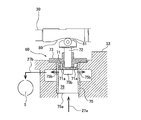
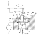
- FIG. 1 It is a top view which shows typically one Embodiment of the fluid coupling of this invention. It is sectional drawing which shows a flow volume adjustment mechanism. It is a figure which shows a cam and a cam follower when a scoop tube advances. It is a figure which shows a cam and cam follower when a scoop tube reverse
- FIG. 1 is a plan view schematically showing one embodiment of the fluid coupling of the present invention.
- the fluid coupling includes an impeller 1 and a runner 2 arranged to face each other, a drive shaft 11 to which the impeller 1 is fixed, and an output shaft 12 to which the runner 2 is fixed.
- the impeller 1 is also called an input side impeller
- the runner 2 is also called an output side impeller.
- the impeller 1 and the runner 2 each have a hemispherical shape having a plurality of radial blades inside, and a fluid chamber 5 is formed between the impeller 1 and the runner 2.
- the input shaft 15 is arranged in parallel with the drive shaft 11.
- the input shaft 15 is supported by radial bearings 16 and 17.
- a large gear 21 is fixed to the input shaft 15, and a small gear 22 that meshes with the large gear 21 is fixed to the drive shaft 11.
- the end of the input shaft 15 is connected to a prime mover (not shown) such as an electric motor or a gas turbine. The rotation of the prime mover is transmitted from the input shaft 15 to the drive shaft 11 via the large gear 21 and the small gear 22.
- the fluid coupling includes a working fluid circulation system 25 that supplies a working fluid to a fluid chamber 5 formed between the impeller 1 and the runner 2, and a scoop tube for increasing or decreasing the amount of the working fluid in the fluid chamber 5 ( Rake pipe) 30.
- the tip 30 a of the scoop tube 30 is located in the impeller casing 7.
- the impeller casing 7 is fixed to the impeller 1 and has a shape surrounding the runner 2.
- the impeller casing 7 rotates together with the impeller 1.
- An actuator (driving device) 31 is connected to the scoop tube 30, and the scoop tube 30 can be moved in the radial direction of the impeller 1 and the runner 2 by the actuator 31.
- the actuator 31 is configured by a combination of a hydraulic servo and an electric or pneumatic actuator, but the actuator 31 may have other configurations.
- the working fluid for example, hydraulic oil
- the working fluid in the impeller casing 7 flows by the rotating impeller 1, and the flowing working fluid rotates the runner 2.
- the working fluid circulation system 25 includes a fluid cooling device 26 for cooling the working fluid, and a working fluid circulation line 27 extending through the fluid cooling device 26.
- the inlet of the working fluid circulation line 27 is connected to the scoop tube 30, and the outlet of the working fluid circulation line 27 communicates with the fluid chamber 5 between the impeller 1 and the runner 2.
- the working fluid discharged from the impeller casing 7 through the scoop tube 30 flows through the working fluid circulation line 27 and is sent to the fluid cooling device 26.
- the working fluid is cooled by heat exchange with the cooling water, and then returned to the fluid chamber 5 through the working fluid circulation line 27. In this way, the working fluid circulates between the fluid chamber 5 and the fluid cooling device 26 by its own pressure raised by the rotating impeller 1.
- the impeller 1 is fixed to the drive shaft 11 and the runner 2 is fixed to the output shaft 12.
- the rotation of the drive shaft 11 is transmitted from the impeller 1 to the runner 2 via the working fluid, and the output shaft 12 rotates.
- the rotational speed of the runner 2 varies depending on the amount of working fluid in the fluid chamber 5 formed between the impeller 1 and the runner 2. Specifically, the rotation speed of the runner 2 increases as the amount of working fluid increases.
- the amount of working fluid in the fluid chamber 5 varies depending on the position of the scoop tube 30. That is, when the tip 30a of the scoop tube 30 moves radially outward, the amount of working fluid decreases, and when the tip 30a of the scoop tube 30 moves radially inward, the amount of working fluid increases.
- the amount of working fluid in the fluid chamber 5, that is, the rotational speed of the output shaft 12 can be changed.
- the drive shaft 11 is rotatably supported by the two radial bearings 40 and 41 and the one thrust bearing 42.
- the output shaft 12 is also rotatably supported by two radial bearings 45 and 46 and one thrust bearing 47.
- the fluid coupling includes a lubricating oil supply system 50 that supplies lubricating oil to the radial bearings 16, 17, 40, 41, 45, 46 and the thrust bearings 42, 47.
- the lubricating oil supply system 50 includes an oil cooling device 54 for cooling the lubricating oil, a lubricating oil supply line 51 extending through the oil cooling device 54, and an oil pump 53 connected to the lubricating oil supply line 51.
- the oil pump 53 is a gear pump that is connected to the input shaft 15 and is operated as the input shaft 15 rotates.
- the oil pump 53 may be a pump that is driven independently of the rotation of the input shaft 15 by an electric motor.
- the lubricating oil is transferred by the oil pump 53 through the lubricating oil supply line 51 to the oil cooling device 54 where it is cooled by the cooling water.
- the cooled lubricating oil is further supplied to the radial bearings 40, 41, 45, 46 and the thrust bearings 42, 47 through the lubricating oil supply line 51.
- the cooled lubricating oil is also supplied to radial bearings 16 and 17 that support the input shaft 15.
- the scoop tube 30 is driven by an actuator 31.
- the actuator 31 includes a cylinder 35 and a piston 38 disposed in the cylinder 35 and connected to the scoop tube 30.
- An oil supply line 57 for supplying oil that moves the scoop tube 30 into the cylinder 35 and an oil discharge line 58 for discharging the oil supplied to the cylinder 35 are connected to the cylinder 35.
- the piston 38 and the scoop tube 30 are moved forward and backward by the pressure of the oil supplied into the cylinder 35.
- the fluid coupling further includes a flow rate adjusting mechanism 60 that adjusts the flow rate of the working fluid circulating in the working fluid circulation line 27.
- the working fluid that has passed through the fluid cooling device 26 flows through the working fluid circulation line 27 and the flow rate adjusting mechanism 60, and is supplied into the fluid chamber 5.
- FIG. 2 is a cross-sectional view showing the flow rate adjusting mechanism 60.
- the flow rate adjusting mechanism 60 includes a housing 75 having a flow path 76 communicating with the working fluid circulation line 27, a valve body 71 movably accommodated in the flow path 76, and a cam 80 movable integrally with the scoop tube 30. And a valve rod 72 whose one end is in contact with the cam 80 and whose other end is connected to the valve body 71.
- the cam 80 may be formed integrally with the scoop tube 30, or may be attached to the scoop tube 30 as a separate body from the scoop tube 30.
- the housing 75 has a working fluid inlet 75a connected to the upstream section 27a of the working fluid circulation line 27 and a working fluid outlet 75b communicating with the downstream section 27b of the working fluid circulation line 27.
- the flow path 76, the working fluid inlet 75a, and the working fluid outlet 75b communicate with each other.
- the working fluid that has flowed through the upstream section 27a of the working fluid circulation line 27 flows into the flow path 76 of the housing 75 through the working fluid inlet 75a, and is discharged from the flow path 76 through the working fluid outlet 75b. It is sent to the fluid chamber 5 through the downstream section 27 b of the fluid circulation line 27.
- one end of the valve stem 72 is composed of a cam follower 81 that is in rolling contact with the cam 80, and the other end of the valve stem 72 is connected to the valve body 71.
- the valve body 71 is fixed to the other end of the valve rod 72 by a screw (not shown).
- the valve stem 72 extends perpendicular to the scoop tube 30. It should be noted that one end of the valve stem 72 may not be configured from the cam follower 81 that rolls into contact with the cam 80 as long as it can contact the cam 80.
- the flow rate adjusting mechanism 60 further includes a valve rod guide 73 that supports the valve rod 72 so that the valve rod 72 can move in its axial direction (longitudinal direction).
- the movement of the valve stem 72 is limited to straight movement by the valve stem guide 73.
- the direction in which the valve stem 72 moves linearly is the axial direction (longitudinal direction) of the valve stem 72.
- the valve body 71 moves integrally with the valve stem 72.
- the valve stem guide 73 is fixed to a fixing member 33 such as a casing, and the valve stem guide 73 and the valve stem 72 block the opening end of the flow path 76 opposite to the working fluid inlet 75a.
- the cam 80 is composed of a concave curved surface.
- the cam follower 81 moves according to the shape of the cam 80, and the valve rod 72 and the valve body 71 move together with the cam follower 81. That is, when the scoop tube 30 moves, the valve body 71 moves in the flow path 76 of the housing 75.
- the working fluid cooled by the fluid cooling device 26 flows into the flow path 76 from the working fluid inlet 75 a of the housing 75 through the upstream section 27 a of the working fluid circulation line 27.
- the working fluid passes through the working fluid outlet 75 b of the housing 75 and is supplied into the fluid chamber 5 through the downstream section 27 b of the working fluid circulation line 27.
- a plurality of working fluid outlets 75 b are formed at equal intervals along the circumferential direction of the housing 75. Although three working fluid outlets 75b are illustrated in FIG. 2, the number and shape of the working fluid outlets 75b are not limited to the present embodiment.
- the valve element 71 is slidably disposed on the inner surface of the housing 75 that forms the flow path 76. More specifically, the valve body 71 is disposed at a position where the valve body 71 covers a part of the working fluid outlet 75b. Therefore, the flow rate adjusting mechanism 60 can adjust the flow rate of the working fluid flowing through the working fluid circulation line 27 by changing the position of the valve body 71 in the housing 75. As shown in FIG. 2, when the cam follower 81 contacts the central region of the cam 80 having a concave curved surface, the opening area of the working fluid outlet 75b is the largest.
- FIG. 3 is a view showing the cam 80 and the cam follower 81 when the scoop tube 30 moves forward, that is, when the scoop tube 30 moves radially outward of the impeller 1 and the runner 2, and FIG. 4 shows the scoop tube 30 retracted.
- the cam 80 and the cam follower 81 are shown.
- the cam follower 81 When the scoop tube 30 moves forward or backward from the position shown in FIG. 2, the cam follower 81 is pushed by the cam 80, and the valve rod 72 and the valve body 71 move together. At this time, the valve body 71 moves in a direction to close most of the working fluid outlet 75b. As a result, the flow rate of the working fluid circulating through the working fluid circulation line 27 decreases.
- the cam follower 81 In the example shown in FIGS. 3 and 4, the cam follower 81 is in contact with the end region of the cam 80 having a curved surface. At this time, the opening area of the working fluid outlet 75b of the housing 75 is the smallest. The working fluid outlet 75 b is not completely closed by the valve body 71, and the working fluid is always supplied into the fluid chamber 5.
- the pressure of the working fluid flowing in the flow path 76 of the housing 75 acts on the valve body 71. Therefore, when the scoop tube 30 moves in a direction in which the cam follower 81 moves toward the central region of the cam 80, the valve follower 71 moves in a direction to open the working fluid outlet 75b while the cam follower 81 pushes the cam 80. As a result, the flow rate of the working fluid circulating through the working fluid circulation line 27 increases.
- the valve body 71 is formed with a plurality of pressure equalizing holes 71 a extending in the axial direction of the valve rod 72. These pressure equalizing holes 71 a are through holes, and are arranged at equal intervals in the circumferential direction of the valve body 71. When the valve body 71 moves, a part of the working fluid moves through the pressure equalizing hole 71a, so that the valve body 71 can move smoothly. Accordingly, it is possible to prevent a large load from being applied to the scoop tube 30 from the cam follower 81 when the scoop tube 30 moves.
- the slip loss is small. Therefore, the operation is performed to reduce the stirring loss of the working fluid and improve the efficiency. A smaller fluid flow rate is preferred.
- the cam follower 81 when the cam follower 81 is in contact with the end region of the cam 80, that is, when the output shaft 12 is rotating at high speed or low speed, the amount of the working fluid flowing through the working fluid circulation line 27. Can be reduced. Therefore, the efficiency of the fluid coupling can be improved.
- the cam 80 that can move integrally with the scoop tube 30 is provided, and the valve rod 72 has a simple structure in which one end of the valve rod 72 is brought into contact with the cam 80. It is not necessary to provide an actuator.
- the present invention can be used for a flow rate adjusting mechanism for adjusting the flow rate of the working fluid of the fluid coupling.
- the present invention can be used for a fluid coupling including such a flow rate adjusting mechanism.
Landscapes
- Engineering & Computer Science (AREA)
- General Engineering & Computer Science (AREA)
- Mechanical Engineering (AREA)
- Mechanically-Actuated Valves (AREA)
Abstract
Description
本発明の好ましい態様は、前記カムは、窪んだ湾曲面から構成されていることを特徴とする。
本発明の好ましい態様は、前記弁棒がその軸方向に移動可能なように前記弁棒を支持する弁棒ガイドをさらに備え、前記弁棒ガイドおよび前記弁棒は前記流路の開口端を塞いでおり、前記弁体には均圧孔が形成されていることを特徴とする。
本発明の好ましい態様は、前記カムは、窪んだ湾曲面から構成されていることを特徴とする。
本発明の好ましい態様は、前記流量調整機構は、前記弁棒がその軸方向に移動可能なように前記弁棒を支持する弁棒ガイドをさらに備え、前記弁棒ガイドおよび前記弁棒は前記流路の開口端を塞いでおり、前記弁体には均圧孔が形成されていることを特徴とする。
2 ランナ
5 流体室
7 インペラケーシング
11 駆動軸
12 出力軸
15 入力軸
16,17 ラジアル軸受
21 大歯車
22 小歯車
25 作動流体循環システム
26 流体冷却装置
27 作動流体循環ライン
30 スクープチューブ(すくい管)
31 アクチュエータ(駆動装置)
33 固定部材
35 シリンダ
38 ピストン
40,41,45,46 ラジアル軸受
42,47 スラスト軸受
50 潤滑油供給システム
51 潤滑油供給ライン
53 油ポンプ
54 油冷却装置
57 給油ライン
58 排油ライン
60 流量調整機構
71 弁体
72 弁棒
73 弁棒ガイド
75 ハウジング
75a 作動流体入口
75b 作動流体出口
76 流路
80 カム
81 カムフォロア
Claims (8)
- 流体継手の作動流体の流量を調整する流量調整機構であって、
作動流体循環ラインに連通する流路を有するハウジングと、
前記流路内に移動可能に収容された弁体と、
インペラとランナとの間に形成される流体室内にある前記作動流体の量を調整するためのスクープチューブと一体に移動可能なカムと、
一端が前記カムに接触し、他端が前記弁体に接続された弁棒とを備えることを特徴とする流量調整機構。 - 前記弁棒の前記一端は、前記カムに転がり接触するカムフォロアから構成されていることを特徴とする請求項1に記載の流量調整機構。
- 前記カムは、窪んだ湾曲面から構成されていることを特徴とする請求項1または2に記載の流量調整機構。
- 前記弁棒がその軸方向に移動可能なように前記弁棒を支持する弁棒ガイドをさらに備え、
前記弁棒ガイドおよび前記弁棒は前記流路の開口端を塞いでおり、
前記弁体には均圧孔が形成されていることを特徴とする請求項1乃至3のいずれか一項に記載の流量調整機構。 - 互いに向き合って配置されたインペラおよびランナと、
前記インペラと前記ランナとの間に形成される流体室内にある作動流体の量を調整するスクープチューブと、
作動流体を冷却する流体冷却装置と、
前記流体室と前記流体冷却装置との間で作動流体を循環させる作動流体循環ラインと、
前記作動流体循環ラインを循環する作動流体の流量を調整する流量調整機構とを備え、
前記流量調整機構は、
前記作動流体循環ラインに連通する流路を有するハウジングと、
前記流路内に移動可能に収容された弁体と、
前記スクープチューブと一体に移動可能なカムと、
一端が前記カムに接触し、他端が前記弁体に接続された弁棒とを備えることを特徴とする流体継手。 - 前記弁棒の前記一端は、前記カムに転がり接触するカムフォロアから構成されていることを特徴とする請求項5に記載の流体継手。
- 前記カムは、窪んだ湾曲面から構成されていることを特徴とする請求項5または6に記載の流体継手。
- 前記流量調整機構は、前記弁棒がその軸方向に移動可能なように前記弁棒を支持する弁棒ガイドをさらに備え、
前記弁棒ガイドおよび前記弁棒は前記流路の開口端を塞いでおり、
前記弁体には均圧孔が形成されていることを特徴とする請求項5乃至7のいずれか一項に記載の流体継手。
Priority Applications (1)
| Application Number | Priority Date | Filing Date | Title |
|---|---|---|---|
| KR1020187020719A KR20180098587A (ko) | 2015-12-25 | 2016-10-21 | 유량 조정 기구 및 유체 커플링 |
Applications Claiming Priority (2)
| Application Number | Priority Date | Filing Date | Title |
|---|---|---|---|
| JP2015255350A JP2017116078A (ja) | 2015-12-25 | 2015-12-25 | 流量調整機構および流体継手 |
| JP2015-255350 | 2015-12-25 |
Publications (1)
| Publication Number | Publication Date |
|---|---|
| WO2017110228A1 true WO2017110228A1 (ja) | 2017-06-29 |
Family
ID=59089973
Family Applications (1)
| Application Number | Title | Priority Date | Filing Date |
|---|---|---|---|
| PCT/JP2016/081305 Ceased WO2017110228A1 (ja) | 2015-12-25 | 2016-10-21 | 流量調整機構および流体継手 |
Country Status (3)
| Country | Link |
|---|---|
| JP (1) | JP2017116078A (ja) |
| KR (1) | KR20180098587A (ja) |
| WO (1) | WO2017110228A1 (ja) |
Citations (4)
| Publication number | Priority date | Publication date | Assignee | Title |
|---|---|---|---|---|
| DE1237388B (de) * | 1959-06-02 | 1967-03-23 | Voith Gmbh J M | Stroemungskupplung mit regelbarem Fuellungsgrad |
| JPS52104079U (ja) * | 1976-02-06 | 1977-08-08 | ||
| JPS61168334U (ja) * | 1985-04-10 | 1986-10-18 | ||
| JPS626341Y2 (ja) * | 1981-11-10 | 1987-02-13 |
Family Cites Families (2)
| Publication number | Priority date | Publication date | Assignee | Title |
|---|---|---|---|---|
| JPS6132601U (ja) | 1984-07-31 | 1986-02-27 | 三菱重工業株式会社 | 回転式パイロツト弁 |
| JPH10196686A (ja) | 1996-12-27 | 1998-07-31 | Ebara Corp | 流体継手 |
-
2015
- 2015-12-25 JP JP2015255350A patent/JP2017116078A/ja active Pending
-
2016
- 2016-10-21 WO PCT/JP2016/081305 patent/WO2017110228A1/ja not_active Ceased
- 2016-10-21 KR KR1020187020719A patent/KR20180098587A/ko not_active Withdrawn
Patent Citations (4)
| Publication number | Priority date | Publication date | Assignee | Title |
|---|---|---|---|---|
| DE1237388B (de) * | 1959-06-02 | 1967-03-23 | Voith Gmbh J M | Stroemungskupplung mit regelbarem Fuellungsgrad |
| JPS52104079U (ja) * | 1976-02-06 | 1977-08-08 | ||
| JPS626341Y2 (ja) * | 1981-11-10 | 1987-02-13 | ||
| JPS61168334U (ja) * | 1985-04-10 | 1986-10-18 |
Also Published As
| Publication number | Publication date |
|---|---|
| JP2017116078A (ja) | 2017-06-29 |
| KR20180098587A (ko) | 2018-09-04 |
Similar Documents
| Publication | Publication Date | Title |
|---|---|---|
| WO2009116380A1 (ja) | 油圧サーボ駆動装置、およびこれを用いた可変ターボ過給機 | |
| CN101432535A (zh) | 流体动力轴向滑动轴承及相应的操作方法 | |
| JPH08177777A (ja) | ポンプ | |
| CN110566336B (zh) | 自动温控流量的水泵调速机构 | |
| WO2013120543A1 (en) | Mechanical coolant pump | |
| JP2018517110A (ja) | 流体力学式自動変速機及びこの流体力学式自動変速機を用いる車両 | |
| JP6538550B2 (ja) | 潤滑油の漏洩を防止する軸封装置を有する流体継手 | |
| CN116201938B (zh) | 用于管道的温度调节组件 | |
| RU2539954C2 (ru) | Насос с осевым балансировочным устройством | |
| CN101413513B (zh) | 一种具有变流叶轮的变速器 | |
| WO2017110228A1 (ja) | 流量調整機構および流体継手 | |
| CN107504150A (zh) | 一种新型液力行星调速机构 | |
| US9206814B2 (en) | Energy saving pump with multiple impellers | |
| CN201297367Y (zh) | 一种变流叶轮及使用该叶轮的变速器 | |
| US20120275907A1 (en) | Fluid energy machine | |
| CN109236977B (zh) | 一种带冷却叶片和控制油路的可降工作温度的液力变矩器 | |
| EP2815094B1 (en) | Mechanical coolant pump | |
| US1934936A (en) | Hydraulic transmission | |
| RU2187708C1 (ru) | Центробежный насос | |
| CN209130137U (zh) | 一种带冷却叶片和控制油路的可降工作温度的液力变矩器 | |
| RU2384740C1 (ru) | Шнекоцентробежный насос | |
| CN109372597B (zh) | 一种可调式涡轮增压器 | |
| RU2474514C1 (ru) | Главный редуктор несущего винта | |
| KR20180087358A (ko) | 유체 커플링 | |
| JP2005171828A (ja) | フランシス型ランナ |
Legal Events
| Date | Code | Title | Description |
|---|---|---|---|
| 121 | Ep: the epo has been informed by wipo that ep was designated in this application |
Ref document number: 16878126 Country of ref document: EP Kind code of ref document: A1 |
|
| NENP | Non-entry into the national phase |
Ref country code: DE |
|
| ENP | Entry into the national phase |
Ref document number: 20187020719 Country of ref document: KR Kind code of ref document: A |
|
| WWE | Wipo information: entry into national phase |
Ref document number: 1020187020719 Country of ref document: KR |
|
| 122 | Ep: pct application non-entry in european phase |
Ref document number: 16878126 Country of ref document: EP Kind code of ref document: A1 |