WO2017109976A1 - Dispositif d'estimation de distance, procédé d'estimation de distance et programme - Google Patents
Dispositif d'estimation de distance, procédé d'estimation de distance et programme Download PDFInfo
- Publication number
- WO2017109976A1 WO2017109976A1 PCT/JP2015/086339 JP2015086339W WO2017109976A1 WO 2017109976 A1 WO2017109976 A1 WO 2017109976A1 JP 2015086339 W JP2015086339 W JP 2015086339W WO 2017109976 A1 WO2017109976 A1 WO 2017109976A1
- Authority
- WO
- WIPO (PCT)
- Prior art keywords
- time
- distance
- feature
- vehicle
- moving
- Prior art date
Links
Images


Classifications
-
- G—PHYSICS
- G01—MEASURING; TESTING
- G01C—MEASURING DISTANCES, LEVELS OR BEARINGS; SURVEYING; NAVIGATION; GYROSCOPIC INSTRUMENTS; PHOTOGRAMMETRY OR VIDEOGRAMMETRY
- G01C22/00—Measuring distance traversed on the ground by vehicles, persons, animals or other moving solid bodies, e.g. using odometers, using pedometers
Definitions
- the present invention relates to a technique for estimating a moving distance of a moving object.
- Patent Document 1 discloses a method of correcting a vehicle speed sensor mounted on a moving body by estimating a moving distance of the moving body in a predetermined period.
- the correction device detects the number of output pulses of the vehicle speed sensor from the recognition of the feature A by the image recognition means to the recognition of the feature B, and the feature A and the feature B from the map information. To obtain the distance D. Then, the correction device corrects an arithmetic expression for obtaining the travel distance or travel speed of the vehicle from the output pulse number based on the relationship between the output pulse number and the distance D.
- An object of this invention is to estimate the moving distance of a moving body using arbitrary features.
- Invention of Claim 1 is a distance estimation apparatus, Comprising: The distance from the mobile body to the feature in each of 1st time and 2nd time, and the angle of the advancing direction of the said mobile body, and the direction of the said feature
- Each of the acquisition units includes an acquisition unit, and a calculation unit that calculates a moving distance of the moving body from the first time to the second time based on an acquisition result of the acquisition unit.
- the invention according to claim 7 is a distance estimation method executed by the distance estimation device, wherein the distance from the moving object to the feature at each of the first time and the second time, the traveling direction of the moving object, and the ground An acquisition step of acquiring an angle with the direction of the object, respectively, and a calculation step of calculating a moving distance of the moving body from the first time to the second time based on an acquisition result of the acquisition step. It is characterized by.
- the invention according to claim 8 is a program executed by a distance estimation device including a computer, wherein the distance from the moving object to the feature at each of the first time and the second time, the traveling direction of the moving object, and the The computer as an acquisition unit that acquires an angle with a direction of a feature, and a calculation unit that calculates a moving distance of the moving body from the first time to the second time based on an acquisition result of the acquisition unit. It is made to function.
- An example of the positional relationship between one feature and a moving vehicle is shown. It is a figure explaining average pulse width. It is a flowchart of the process which calculates
- a method for projecting a three-dimensional position of a feature onto a horizontal plane of a vehicle will be described. Another method for projecting a three-dimensional position of a feature onto a horizontal plane of a vehicle is shown.
- a method for calculating the movement distance based on the three-dimensional position of the feature will be described. Another method for calculating the movement distance based on the three-dimensional position of the feature will be described.
- the distance estimation device acquires the distance from the moving object to the feature and the angle between the traveling direction of the moving object and the direction of the feature at the first time and the second time, respectively.
- an calculating unit that calculates a moving distance of the moving body from the first time to the second time based on the acquisition result of the acquiring unit.
- the distance estimation apparatus acquires the distance from the moving object to the feature at each of the first time and the second time, and the angle between the traveling direction of the moving object and the direction of the feature. And based on the acquisition result, the moving distance of the moving body from the first time to the second time is calculated. Thereby, the movement distance of a moving body is computable using the arbitrary features which can be measured from a moving body.
- the calculation unit includes an angle between the traveling direction of the moving body at the first time and the direction of the feature, and the traveling direction of the moving body at the second time. Based on the angle between the direction of the feature and the direction of the feature at the first time and the direction of the feature at the second time, the angle, the first time, and the second time are calculated. The moving distance is calculated based on the distance from the moving body to the feature in each.
- the calculation unit may calculate 1 of the vehicle speed pulse signal based on a moving distance from the first time to the second time and an average pulse width of the vehicle speed pulse signal. Calculate the travel distance per pulse. As a result, the vehicle speed pulse signal can be calibrated based on the calculated moving distance.
- the calculation unit calculates the movement distance when an angular velocity or a steering angle in a yaw direction of the moving body is less than a predetermined threshold. Thereby, the calculation accuracy of the movement distance can be improved.
- the calculation unit changes a time interval from the first time to the second time according to a traveling speed of the moving body.
- the calculation accuracy of the movement distance can be improved.
- the calculation unit shortens the time interval as the traveling speed of the moving body increases.
- the distance estimation method executed by the distance estimation device includes the distance from the moving object to the feature at each of the first time and the second time, the traveling direction of the moving object, and the ground.
- a program executed by a distance estimation device including a computer includes a distance from a moving object to a feature at each of a first time and a second time, a traveling direction of the moving object, and the The computer as an acquisition unit that acquires an angle with a direction of a feature, and a calculation unit that calculates a moving distance of the moving body from the first time to the second time based on an acquisition result of the acquisition unit. Make it work. Thereby, the movement distance of a moving body is computable using the arbitrary features which can be measured from a moving body.
- the above program can be stored in a storage medium and used.
- the vehicle speed is detected using a vehicle speed sensor, and the traveling state is detected using an angular velocity sensor or a steering angle sensor, thereby measuring the movement state of the vehicle. Then, the current position is estimated by integrating these with information measured by the GPS or the external sensor. Therefore, in order to improve the self-position estimation accuracy, it is required to detect the vehicle speed with high accuracy.
- the vehicle speed sensor outputs a vehicle speed pulse signal at a time interval proportional to the output shaft of the transmission or the rotational speed of the wheels, for example. Then, as shown in the following formula (1), the distance coefficient alpha d can be calculated vehicle speed v by dividing a pulse width t p. This distance coefficient ⁇ d is the moving distance per pulse of the vehicle speed pulse signal.
- the moving distance per pulse varies depending on the vehicle type. Further, when the outer diameter of the tire changes due to a change in tire air pressure or tire replacement, the moving distance per pulse also changes. Furthermore, the moving distance per pulse varies depending on the traveling speed. Usually, the running resistance causes a difference between the wheel speed obtained from the vehicle speed pulse and the actual vehicle speed. Since the running resistance is higher during high speed running than during low speed running, the speed difference between the wheel speed and the vehicle body speed is also greater during high speed running than during low speed running. Therefore, the moving distance per pulse differs between high speed traveling and low speed traveling. As described above, in order to obtain the vehicle speed with high accuracy, the distance coefficient needs to be appropriately calibrated and updated.
- the GPS information itself which is a reference, may include a large error.
- the conditions should be strict, but the more strict the conditions, the less the number of times reference information is acquired, and the conflicting problem that the progress of calibration becomes slow. Comes out.
- the distance coefficient updating apparatus does not use GPS information as a reference, but based on the measurement of a feature by an external sensor, the moving distance of the vehicle Is used as a reference for calibration of the vehicle speed pulse signal.
- an external sensor a camera, LiDAR (Light Detection And Ranging), a millimeter wave radar, or the like can be used.
- FIG. 1 is a flowchart illustrating distance coefficient update processing according to the embodiment.
- the update device at time T 1, to measure one feature using external sensors.
- step P2 updating device, at time T 2, which has passed ⁇ T seconds from the time T 1, to measure the same feature as that measured at time T 1.
- step P3 the update device was acquired at time T 1 and time T 2, the distance from the vehicle center position to feature at each time, by using the feature of the angle with respect to the traveling direction of the vehicle, calculates a moving distance ⁇ D the vehicle from time T 1 to time T 2.
- step P4 the update device, an average pulse width t p of the vehicle speed pulse signal from the time T 1 of the time T 2, the elapsed time ⁇ T from the time T 1 to time T 2, determined in step P3
- the moving distance d p per pulse is calculated using the moving distance ⁇ D of the vehicle from time T 1 to time T 2 .
- step P5 the update device updates the distance coefficient ⁇ d using the movement distance d p per pulse obtained in step P4.
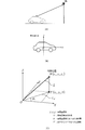
- FIG. 2 shows an example of the positional relationship between one feature and a moving vehicle. Vehicle during the period from the time T 1 time T 2, is to have moved as shown in FIG. First, the update device detects the feature at time T 1, to obtain the angle phi 1 and the distance L 1 and the traveling direction Hd 1 and the direction of the feature of the vehicle from the vehicle to the feature (step P1) .
- the updating device also detects the feature at time T 2 in the same manner as at time T 1, and the angle ⁇ 2 between the distance L 2 from the vehicle to the feature and the traveling direction Hd 1 of the vehicle and the direction of the feature. Is acquired (process P2).
- the update device includes a distance L 1 and the angle phi 1 acquired at time T 1, by using the distance L 2 and the angle phi 2 acquired in time T 2,, the vehicle from time T 1 to time T 2, Is calculated.
- the angle ⁇ defined by the direction of the feature at time T 1 and the direction of the feature at time T 2 is given by the following equation.
- the movement distance ⁇ D is obtained as follows by the cosine theorem.
- Figure 3 is a diagram for explaining the average pulse width t p.
- Average pulse width t p is the pulse width measured between the time T 1 of the time T 2, leave buffers can be calculated by taking the average as in the following formula (6).
- the average pulse width can also be obtained by sequential calculation using Equation (7).
- the average pulse width is obtained by sequential calculation, it is not necessary to buffer the measured pulse width, so that the amount of memory used in the apparatus can be reduced.
- FIG. 4 is a flowchart of a process for obtaining the average pulse width by sequential calculation.
- the update unit resets the coefficient k indicating the number of detected pulses to "0" (step S51), and acquires the current time T (step S52).
- the update unit determines whether the present time T reaches time T 2 (step S53).
- the update device by the equation (7), obtained by dividing the difference between the average pulse width t p and the current pulse width t k at the time by a factor k value (t k -t p) / k , that is, to update the current pulse width t k average pulse t p the variation of adding the average pulse width t p of the time average pulse width t p by, step S52 Return to.
- step S53 if the current time T reaches time T 2 (step S53: YES), the process ends.
- the update device updates the distance coefficient ⁇ d using the movement distance d p obtained in step P4. Specifically, the obtained moving distance d p is set as a new distance coefficient ⁇ d .
- the updated distance coefficient ⁇ d obtained in this way is used for calculation of the vehicle speed v by the equation (1).
- a vehicle coordinate system (XYZ coordinate system) is defined as shown in FIG.
- the X axis indicates the traveling direction of the vehicle
- the Y axis indicates the direction perpendicular to the traveling direction of the vehicle in the horizontal plane of the vehicle
- the Z axis indicates the height direction of the vehicle.
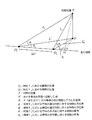
- the orthogonal projection from the point P to the XY plane (the leg of the perpendicular line dropped from the point P to the XY plane) is set as a point P ′
- the length L xy of the line segment OP ′ and the line segment OP ′ The angle ⁇ xy formed with the X axis can be calculated as follows.
- step P1 ⁇ P3 determines the horizontal distance L xy and angle phi xy using equation (12), it may be used. Specifically, in the process P1, the horizontal distance L 1xy and the angle ⁇ 1xy are obtained. Similarly, in the process P2, the horizontal distance L 2xy and the angle ⁇ 2xy are obtained. And based on these, movement distance (DELTA) D is calculated
- the length L xy of the line segment OP ′ can be calculated as follows.
- the horizontal distances L 1xy and L 2xy and the angles ⁇ 1xy and ⁇ 2xy may be used as in (i).
- an orthogonal projection from the point P to the XY plane (perpendicular foot dropped from the point P to the XY plane) is set as a point P ′, and a normal foot dropped from the point P ′ to the vehicle travel path is defined as a point H ′.
- the length of the line segment O 1 P ′ is obtained by the equation (10-1)
- the length of the line segment P′H is obtained by the equation (10-2)
- the length of the line segment PP ′ is It is obtained by the formula (10-3). Therefore, the length of the line segment PH is obtained by Expression (10-4), and Expression (10-5) is established with respect to an angle ⁇ 1 formed by the vehicle traveling direction and the feature position P at time T 1 .
- alpha 1 is represented by the formula (11).
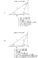
- Example 2 As in Example 1, using an external sensor capable of measuring the distance and angle to the feature, as shown in FIG. 7, the distance L from the vehicle to the feature, the traveling direction of the vehicle (the X axis of the vehicle coordinate system) ) And the elevation angle ⁇ of the feature with respect to the horizontal plane of the vehicle (the XY plane of the vehicle coordinate system). Specifically, at time T 1, the distance L 1 from the vehicle to the feature, the azimuth angle theta 1 of the feature, can retrieve elevation angle phi 1 is the feature, at time T 2, the distance from the vehicle to feature L 2. Assume that the azimuth angle ⁇ 2 of the feature and the elevation angle ⁇ 2 of the feature have been acquired.
- PH can be obtained using either the measurement result at time T 1 or the measurement result at time T 2 .
- PH is obtained by Expression (16-4).
- FIG. 9 is a block diagram illustrating the configuration of the update device 1 according to the embodiment.
- the update device 1 determines the movement distance ⁇ D based on the measurement result of one feature by the external sensor.
- the update device 1 includes a gyro sensor 10, a vehicle speed sensor 11, an external sensor 12, a traveling direction acquisition unit 13, a vehicle speed pulse measurement unit 14, a feature measurement unit 15, and a distance coefficient calibration unit. 17 and a movement distance calculation unit 18.
- the traveling direction acquisition unit 13, the vehicle speed pulse measurement unit 14, the feature measurement unit 15, the distance coefficient calibration unit 17, and the movement distance calculation unit 18 are executed by executing a program prepared in advance by a computer such as a CPU. Can be realized.
- the traveling direction acquisition unit 13 acquires the traveling directions Hd 1 and Hd 2 of the vehicle based on the output of the gyro sensor 10 and supplies them to the feature measurement unit 15 and the distance coefficient calibration unit 17.
- Vehicle speed pulse measuring unit 14 a vehicle speed pulse outputted from the vehicle speed sensor 11 measures and supplies the distance coefficient calibration unit 17 calculates the like mean pulse width t p of the vehicle speed pulse signal.
- the external sensor 12 is, for example, a camera, LiDAR, millimeter wave radar, or the like, and the feature measuring unit 15 measures the distance to the feature based on the output of the external sensor 12. Specifically, the feature measurement unit 15 measures the distance L 1 from the vehicle to one feature at time T 1 , and the vehicle travel direction Hd 1 supplied from the travel direction acquisition unit 13 and its An angle ⁇ 1 formed with the direction of the feature is calculated and supplied to the movement distance calculation unit 18. Further, feature measurement unit 15, at time T 2, with measuring the distance L 2 to the same feature from the vehicle, the traveling direction Hd 2 and the direction of the feature of the supplied vehicle from the traveling direction acquisition unit 13 calculating the angle phi 2 and is supplied to the moving distance calculating unit 18.
- the moving distance calculation unit 18 calculates the moving distance of the vehicle according to the above formulas (3) to (4).
- ⁇ D is calculated and supplied to the distance coefficient calibration unit 17.
- the moving distance d p per pulse (i.e. , A distance coefficient ⁇ d ) is calculated.
- the vehicle body speed may be calculated from the obtained movement distance per pulse.
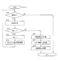
- FIG. 10 is a flowchart of the distance coefficient update process according to the embodiment.
- the updating device 1 determines whether or not the vehicle is traveling straight ahead based on the traveling direction of the vehicle output by the traveling direction acquisition unit 13 (step S11). This is because the accuracy of the movement distance ⁇ D output by the movement distance calculation unit 18 decreases when the vehicle is not traveling straight ahead.
- the gyro sensor 10 can detect the angular velocity ⁇ in the yaw direction of the vehicle, it may be determined that the vehicle is traveling straight when
- the steering angle ⁇ of the vehicle it may be determined that the vehicle is traveling straight when
- step S11 If the vehicle is not traveling straight (step S11: NO), the process ends. On the other hand, when the vehicle is traveling straight (step S11: YES), the update device 1 measures one feature and acquires the distance L and the angle ⁇ from the vehicle to the feature (step S12).
- step S13 NO
- the updating device 1 calculates the movement distance ⁇ D as described above (step S16), and calculates the movement distance d p per pulse using the movement distance ⁇ D. (step S17), and updates the distance coefficient alpha d (step S18). Then, the process ends.
- the movement distance d p per pulse obtained in the above-described distance coefficient update process is an average value of the movement distance per pulse during the time interval ⁇ T from time T 1 to time T 2 . Therefore, the large variation of the pulse width of the time interval [Delta] T, the accuracy of the moving distance d p which is calculated is deteriorated. Therefore, it is desirable that the number of pulses during the time interval ⁇ T is as small as possible.
- the number of pulses per unit time varies depending on the running speed of the vehicle. For example, consider the number of pulses per second as shown in FIG. In a vehicle type that outputs two pulses per tire rotation, the number of pulses per second is 3 pulses at 10 km / h, 17 pulses at 50 km / h, and 35 pulses at 100 km / h, and there is a large difference depending on the running speed.
- FIG. 11B shows the relationship between the traveling speed and the pulse width.
- ⁇ T 300 ms when the traveling speed is less than 20 km / h
- ⁇ T 200 ms when the speed is 20 km / h or more and less than 30 km / h.
- the number of pulses that can be measured during the time interval ⁇ T is about 1 pulse or 2 pulses, and the moving distance is high.
- d p can be calculated.
- Modification 2 If the external sensor is attached to a low position of the vehicle, it is considered that the occlusion increases by surrounding vehicles, and the frequency with which a suitable feature for updating the distance coefficient can be detected decreases. Therefore, it is preferable to install the external sensor so that the upper side can be measured above the height of the surrounding vehicle. Thereby, since the detection frequency of the feature increases and the number of updates of the distance coefficient increases, the accuracy of the distance coefficient can be improved.
- the present invention can be used for an apparatus mounted on a moving body.
Abstract
La présente invention concerne un dispositif d'estimation de distance qui acquiert la distance entre un objet physique et un objet mobile à un premier instant et à un second instant et qui acquiert également l'angle formé par la direction de déplacement de l'objet mobile et la direction de l'objet physique. Sur la base des résultats d'acquisition, le dispositif calcule la distance de déplacement de l'objet mobile entre le premier instant et le second instant.
Priority Applications (1)
| Application Number | Priority Date | Filing Date | Title |
|---|---|---|---|
| PCT/JP2015/086339 WO2017109976A1 (fr) | 2015-12-25 | 2015-12-25 | Dispositif d'estimation de distance, procédé d'estimation de distance et programme |
Applications Claiming Priority (1)
| Application Number | Priority Date | Filing Date | Title |
|---|---|---|---|
| PCT/JP2015/086339 WO2017109976A1 (fr) | 2015-12-25 | 2015-12-25 | Dispositif d'estimation de distance, procédé d'estimation de distance et programme |
Publications (1)
| Publication Number | Publication Date |
|---|---|
| WO2017109976A1 true WO2017109976A1 (fr) | 2017-06-29 |
Family
ID=59089803
Family Applications (1)
| Application Number | Title | Priority Date | Filing Date |
|---|---|---|---|
| PCT/JP2015/086339 WO2017109976A1 (fr) | 2015-12-25 | 2015-12-25 | Dispositif d'estimation de distance, procédé d'estimation de distance et programme |
Country Status (1)
| Country | Link |
|---|---|
| WO (1) | WO2017109976A1 (fr) |
Citations (5)
| Publication number | Priority date | Publication date | Assignee | Title |
|---|---|---|---|---|
| JP2005006081A (ja) * | 2003-06-12 | 2005-01-06 | Denso Corp | 画像サーバ、画像収集装置、および画像表示端末 |
| JP2008008783A (ja) * | 2006-06-29 | 2008-01-17 | Toyota Motor Corp | 車輪速パルス補正装置 |
| JP2012073810A (ja) * | 2010-09-29 | 2012-04-12 | Hitachi Ltd | 路面状況推定装置および路面状況推定方法 |
| JP2012189467A (ja) * | 2011-03-11 | 2012-10-04 | Casio Comput Co Ltd | 測位装置、歩幅データ補正方法およびプログラム |
| JP2014232411A (ja) * | 2013-05-29 | 2014-12-11 | 富士通テン株式会社 | 携帯端末、及び、危険報知システム |
-
2015
- 2015-12-25 WO PCT/JP2015/086339 patent/WO2017109976A1/fr active Application Filing
Patent Citations (5)
| Publication number | Priority date | Publication date | Assignee | Title |
|---|---|---|---|---|
| JP2005006081A (ja) * | 2003-06-12 | 2005-01-06 | Denso Corp | 画像サーバ、画像収集装置、および画像表示端末 |
| JP2008008783A (ja) * | 2006-06-29 | 2008-01-17 | Toyota Motor Corp | 車輪速パルス補正装置 |
| JP2012073810A (ja) * | 2010-09-29 | 2012-04-12 | Hitachi Ltd | 路面状況推定装置および路面状況推定方法 |
| JP2012189467A (ja) * | 2011-03-11 | 2012-10-04 | Casio Comput Co Ltd | 測位装置、歩幅データ補正方法およびプログラム |
| JP2014232411A (ja) * | 2013-05-29 | 2014-12-11 | 富士通テン株式会社 | 携帯端末、及び、危険報知システム |
Similar Documents
| Publication | Publication Date | Title |
|---|---|---|
| CN106289275B (zh) | 用于改进定位精度的单元和方法 | |
| WO2018225198A1 (fr) | Procédé et dispositif de correction de données de carte | |
| WO2012086401A1 (fr) | Dispositif d'aide à la conduite | |
| JP6806891B2 (ja) | 情報処理装置、制御方法、プログラム及び記憶媒体 | |
| JP2013145168A (ja) | 車載用ジャイロの角速度誤差補正装置 | |
| US20200132462A1 (en) | Sensor calibration device and sensor calibration program product | |
| WO2017109978A1 (fr) | Dispositif d'estimation de distance, procédé d'estimation de distance, et programme | |
| US11318950B2 (en) | Calculation apparatus, control method, program and storage medium | |
| JP2023164553A (ja) | 位置推定装置、推定装置、制御方法、プログラム及び記憶媒体 | |
| JP6503477B2 (ja) | 距離推定装置、距離推定方法及びプログラム | |
| JP6790951B2 (ja) | 地図情報学習方法及び地図情報学習装置 | |
| CN113306559A (zh) | 在路形估计中对于垂直道路曲度的补偿 | |
| JP7025293B2 (ja) | 自車位置推定装置 | |
| JP6707627B2 (ja) | 測定装置、測定方法、及び、プログラム | |
| WO2017168588A1 (fr) | Dispositif de mesure, procédé de mesure et programme | |
| WO2017109976A1 (fr) | Dispositif d'estimation de distance, procédé d'estimation de distance et programme | |
| WO2018163750A1 (fr) | Dispositif d'estimation de distance, procédé d'estimation de distance, et programme | |
| KR101676145B1 (ko) | 곡률계산 장치 및 곡률보정 방법 | |
| JP2017181195A (ja) | 測定装置、測定方法、及び、プログラム | |
| JP2022179642A (ja) | 距離推定装置 | |
| WO2017109979A1 (fr) | Dispositif d'estimation de distance, procédé d'estimation de distance et programme | |
| JP2019124698A (ja) | 距離推定装置 | |
| JPH08338733A (ja) | 車両走行方位算出装置 | |
| JP2023022232A (ja) | 速度算出装置 | |
| WO2017094065A1 (fr) | Dispositif de calcul de vitesse, procédé de commande, programme et support de stockage |
Legal Events
| Date | Code | Title | Description |
|---|---|---|---|
| 121 | Ep: the epo has been informed by wipo that ep was designated in this application |
Ref document number: 15911410 Country of ref document: EP Kind code of ref document: A1 |
|
| NENP | Non-entry into the national phase |
Ref country code: DE |
|
| 122 | Ep: pct application non-entry in european phase |
Ref document number: 15911410 Country of ref document: EP Kind code of ref document: A1 |
|
| NENP | Non-entry into the national phase |
Ref country code: JP |