WO2017109872A1 - 太陽光発電システム - Google Patents
太陽光発電システム Download PDFInfo
- Publication number
- WO2017109872A1 WO2017109872A1 PCT/JP2015/085917 JP2015085917W WO2017109872A1 WO 2017109872 A1 WO2017109872 A1 WO 2017109872A1 JP 2015085917 W JP2015085917 W JP 2015085917W WO 2017109872 A1 WO2017109872 A1 WO 2017109872A1
- Authority
- WO
- WIPO (PCT)
- Prior art keywords
- solar cell
- power generation
- cell module
- light emitter
- power
- Prior art date
- Legal status (The legal status is an assumption and is not a legal conclusion. Google has not performed a legal analysis and makes no representation as to the accuracy of the status listed.)
- Ceased
Links
Images



Classifications
-
- H—ELECTRICITY
- H02—GENERATION; CONVERSION OR DISTRIBUTION OF ELECTRIC POWER
- H02J—ELECTRIC POWER NETWORKS; CIRCUIT ARRANGEMENTS OR SYSTEMS FOR SUPPLYING OR DISTRIBUTING ELECTRIC POWER; SYSTEMS FOR STORING ELECTRIC ENERGY
- H02J3/00—Circuit arrangements for AC mains or AC distribution networks
- H02J3/38—Arrangements for feeding a single network from two or more generators or sources in parallel; Arrangements for feeding already energised networks from additional generators or sources in parallel
-
- H—ELECTRICITY
- H02—GENERATION; CONVERSION OR DISTRIBUTION OF ELECTRIC POWER
- H02M—APPARATUS FOR CONVERSION BETWEEN AC AND AC, BETWEEN AC AND DC, OR BETWEEN DC AND DC, AND FOR USE WITH MAINS OR SIMILAR POWER SUPPLY SYSTEMS; CONVERSION OF DC OR AC INPUT POWER INTO SURGE OUTPUT POWER; CONTROL OR REGULATION THEREOF
- H02M7/00—Conversion of AC power input into DC power output; Conversion of DC power input into AC power output
- H02M7/42—Conversion of DC power input into AC power output without possibility of reversal
- H02M7/44—Conversion of DC power input into AC power output without possibility of reversal by static converters
- H02M7/48—Conversion of DC power input into AC power output without possibility of reversal by static converters using discharge tubes with control electrode or semiconductor devices with control electrode
-
- H—ELECTRICITY
- H02—GENERATION; CONVERSION OR DISTRIBUTION OF ELECTRIC POWER
- H02S—GENERATION OF ELECTRIC POWER BY CONVERSION OF INFRARED RADIATION, VISIBLE LIGHT OR ULTRAVIOLET LIGHT, e.g. USING PHOTOVOLTAIC [PV] MODULES
- H02S50/00—Monitoring or testing of PV systems, e.g. load balancing or fault identification
-
- Y—GENERAL TAGGING OF NEW TECHNOLOGICAL DEVELOPMENTS; GENERAL TAGGING OF CROSS-SECTIONAL TECHNOLOGIES SPANNING OVER SEVERAL SECTIONS OF THE IPC; TECHNICAL SUBJECTS COVERED BY FORMER USPC CROSS-REFERENCE ART COLLECTIONS [XRACs] AND DIGESTS
- Y02—TECHNOLOGIES OR APPLICATIONS FOR MITIGATION OR ADAPTATION AGAINST CLIMATE CHANGE
- Y02B—CLIMATE CHANGE MITIGATION TECHNOLOGIES RELATED TO BUILDINGS, e.g. HOUSING, HOUSE APPLIANCES OR RELATED END-USER APPLICATIONS
- Y02B10/00—Integration of renewable energy sources in buildings
- Y02B10/10—Photovoltaic [PV]
-
- Y—GENERAL TAGGING OF NEW TECHNOLOGICAL DEVELOPMENTS; GENERAL TAGGING OF CROSS-SECTIONAL TECHNOLOGIES SPANNING OVER SEVERAL SECTIONS OF THE IPC; TECHNICAL SUBJECTS COVERED BY FORMER USPC CROSS-REFERENCE ART COLLECTIONS [XRACs] AND DIGESTS
- Y02—TECHNOLOGIES OR APPLICATIONS FOR MITIGATION OR ADAPTATION AGAINST CLIMATE CHANGE
- Y02E—REDUCTION OF GREENHOUSE GAS [GHG] EMISSIONS, RELATED TO ENERGY GENERATION, TRANSMISSION OR DISTRIBUTION
- Y02E10/00—Energy generation through renewable energy sources
- Y02E10/50—Photovoltaic [PV] energy
Definitions
- Embodiments of the present invention relate to a solar cell system.
- Photovoltaic power generation using solar cells is attracting attention as a power generation method that generates less CO 2 .
- the output per general solar battery cell is small.
- a practical solar power generation system configures a solar cell module in which a plurality of substrings in which a plurality of solar cells are connected in series are connected in series or in parallel so that a large amount of power can be obtained.
- Such a solar power generation system is configured such that desired power can be obtained by connecting a large number of solar cell modules to a single device called a PCS (power conditioner).
- the PCS basically has an inverter function for performing DC / AC conversion.
- the PCS also has an MPPT (MPP: Maximum point Tracker) function that follows an operating point at which the output power becomes maximum while the amount of solar radiation changes every moment.
- MPPT Maximum point Tracker
- such a PCS is installed in a place where a solar cell module S is mounted on a roof R at a place where an indoor or outdoor visual inspection can be performed.
- B is a frame for installing the solar cell module S on the roof R. For this reason, even if there is an abnormality such as ignition or smoke in the PCS, it can be visually confirmed.
- the inverter is installed in a place where it can be inspected.
- a micro inverter M has been developed as a control device for a solar cell module S instead of the PCS.
- (A) is the surface on the light receiving side of the solar cell module S
- (B) is the back surface.
- the micro inverter M is a small PCS installed for each solar cell module S and having an inverter function and an MPPT function.
- the micro inverter M is attached to the back side of each solar cell module S or to a gantry that fixes each solar cell module S.
- attached so that the micro inverter M might be united with the solar cell module S is called AC module.
- the input side of the micro inverter M is connected to the output side of the solar cell module S via a DC cable C1.
- the output side of the micro inverter M is connected to a grid interconnection device (not shown) via an AC cable C2, and each micro inverter M is linked to the grid via this grid interconnection device.
- MPPT is performed for each solar cell module S, and the amount of power generation of the entire solar power generation system can be increased. Moreover, the influence which the functional fall of each solar cell module S has on the whole electric power generation amount can be suppressed. Furthermore, the increase / decrease change of the solar cell module S in the solar power generation system becomes easy.
- the micro inverter M is a kind of inverter, it must be visually inspected.
- the micro inverter M is attached to the back side of each solar cell module S as described above, or is installed on the mount B for attaching each solar cell module S to the roof R. For this reason, as shown in FIG. 7, in the state where the solar cell module S is installed on the roof R, the gap where the microinverter M can be seen is very narrow, and inspection is difficult.
- the micro inverter is connected to a monitoring device that monitors the operation status of each unit, and is configured to be able to check the operation status via a display device. Therefore, the monitoring apparatus stores position information indicating where the micro inverter is installed on the roof when the solar cell module S is installed. However, if an operator's input mistake or loss of position information occurs, it becomes difficult to specify the micro inverter displayed on the display device from the plurality of micro inverters. Therefore, even if a micro inverter in which an abnormality is detected is displayed on the display device, it is necessary to search for the micro inverter.
- such a subject is the same also in the apparatus for photovoltaic power generation which performs monitoring or control, such as the monitoring apparatus separately connected to the solar cell module S, DC / DC optimizer.
- the embodiment of the present invention has been proposed in order to solve the problems of the prior art as described above.
- the purpose is to provide a photovoltaic power generation system that is easy to visually inspect and grasp the position even for photovoltaic power generation devices individually connected to a plurality of solar cell modules.
- a solar power generation system includes a plurality of solar cell modules and a plurality of solar cells that are individually connected to each of the solar cell modules and control or monitor each solar cell module.
- a photovoltaic device, a light emitter is connected to the photovoltaic device, and the luminous body is provided so as to protrude from a frame surrounding the solar cell module.
- FIG. 1 is an external view of a photovoltaic power generation system 100 of the present embodiment.
- the solar power generation system 100 is a system that converts DC power output by solar power generation into AC power and supplies it to a main circuit in a house or reversely flows to an external power system.
- the solar power generation system 100 includes a plurality of solar cell modules 1 and a plurality of micro inverters (hereinafter referred to as MICs) 2.
- MICs micro inverters
- the plurality of solar cell modules 1 are arranged adjacent to each other as shown in FIG.
- the solar cell module 1 is fixed to the roof R by a gantry 4.
- Various configurations can be applied to the gantry 4.
- columnar support members 40 parallel to the ridge are fixed to the roof R at a predetermined interval.
- Near the both ends of the back surface of the solar cell module 1 are fixed to the support member 40 by fixing brackets (not shown).
- the solar cell modules 1 in the same row are supported by a common support member 40.
- the solar cell module 1 has an aggregate of a plurality of solar cells 11 as shown in FIG.
- a plurality of solar cells 11 in each solar cell module 1 are arranged vertically and horizontally. These solar cells 11 are supported by a transparent rectangular support plate 12 on the light receiving surface side (FIG. 2A) and supported by a rectangular back sheet 13 on the side opposite to the light receiving surface (FIG. 2B). ing.
- the solar cell module 1 is formed as a rectangular panel.
- the light receiving surface side is the front surface side
- the anti-light receiving surface side is the back surface side.
- the solar cell module 1 includes a junction box 15 as shown in FIG.
- the junction box 15 is a terminal for taking out the DC power generated by the solar cell module 1, and is connected to the DC cable C1 for connection to the MIC2.
- the plurality of MICs 2 are individually connected for each of the solar cell modules 1 described above.
- a light emitter L1 is connected to each MIC2.
- An LED may be used as the light emitter L1.
- the LED may be capable of emitting light in a plurality of colors, and may be configured to emit light in red and green, for example.
- the light emitter L1 is connected to one side surface of the MIC 2 via the support member L2 on the back surface side of the solar cell module 1.
- the length of the support member L2 can be set as appropriate, but the length is such that the light emitter L1 protrudes outside the frame 14.
- the light emitter L1 protrudes from the frame 14 on the surface side of the solar cell module 1, and is arranged so that an operator or the like can see it. If the light emitter L1 is provided so as to protrude from the frame 14, the support member L2 may not be disposed. For example, even when the light emitter L1 is provided so as to be hidden behind the frame 14, the light emitter L1 may be configured to be movable and moved so as to protrude from the frame 14.
- the light emitter L1 is connected to the control circuit 28 on the system side of the MIC2, and operations such as lighting and blinking are controlled.
- the configuration of the MIC 2 including the control circuit 28 will be described in detail.
- MIC2 is an apparatus for photovoltaic power generation that has an inverter function and an MPPT function and controls the solar cell module 1.
- the inverter function is a function that mainly converts DC power from the solar cell module 1 into AC power.
- the MPPT function has a maximum power point tracking function.
- Each processing unit that executes each function in the MIC 2 is housed in a metal casing. The inside of the housing of the MIC 2 is sealed with a filler.
- the MIC 2 includes members for power conversion such as a filter 21, a DC / DC converter 22, an insulating transformer 23, a rectifier circuit 24, a DC / AC converter 25, and a filter 26. Moreover, it has the control circuits 27 and 28 which are control circuits which implement
- Filters 21 and 26 are filters for removing noise.
- the filter 26 has a function of removing harmonics due to pulse width modulation control.
- the filters 21 and 26 can be configured using a reactor or a capacitor.
- the output side from the filter 26 is connected to an AC system via wiring.
- the DC / DC converter 22 is a converter that converts the power supplied from the solar cell module 1 into DC power having a predetermined voltage based on a control signal from the control circuit 27.
- the insulation transformer 23 insulates between the DC / DC converter 22 and the power system.
- the rectifier circuit 24 includes a thyristor and a diode, which are rectifier elements, and rectifies the output voltage of the DC / DC converter 22.
- the DC / AC converter 25 is a converter that converts DC power from the solar cell module 1 into AC power based on a control signal from the control circuit 28.
- the control circuit 27 is an MPPT control unit that is connected to the DC / DC converter 22 and performs maximum power point tracking control so that the output characteristics of the solar cell module 1 are maximized.
- the control circuit 28 is an inverter control unit that is connected to the DC / AC converter 25 and performs control for converting DC power from the solar cell module 1 into AC power.
- the control circuits 27 and 28 can be configured by a microcontroller (MCU: “micro control unit”).
- the control circuits 27 and 28 are provided with power supply circuits 37 and 38 for supplying power to the control circuits 27 and 28, respectively.
- the power supply circuit 37 is a circuit that generates control power based on DC power obtained from the solar cell module 1.
- the power supply circuit 37 is connected so as to be able to acquire DC power that has passed through the filter 21.
- the power supply circuit 38 is a circuit that generates control power based on DC power obtained from the solar cell module 1 or AC power obtained from the power system.
- the power supply circuit 38 is connected so as to be able to acquire DC power that has passed through the rectifier circuit 24.
- the power supply circuit 38 is configured to be able to acquire AC power from the power system. Therefore, the power supply circuit 38 includes a transformer and an AC / DC converter for converting AC power of the power system into DC power.
- the communication unit C and the light emitter L1 are connected to the control circuit 28.
- the control circuit 28 has a function of controlling the communication unit C and the light emitter L1.
- the communication unit C communicates with a gateway that is a remote monitoring device of the photovoltaic power generation system 100 by wire or wirelessly.
- the gateway communicates with an operation terminal such as a management company or a user operation terminal. An instruction from the operation terminal is transmitted to the MIC 2 via the gateway, and information acquired by the MIC 2 is transmitted to the operation terminal via the gateway.
- the control circuit 28 has a light emitter control circuit (not shown) that controls the light emitter L1.
- the light emitter control circuit controls operations such as lighting and blinking of the light emitter L1.
- the control of lighting and blinking may be performed in accordance with the control state of the solar cell module 1 and the MIC 2.
- the control circuit 28 that has received the lighting instruction from the operation terminal via the communication unit C can be configured to perform control to turn on the light emitter L1.
- control circuit 28 may perform control to turn on the light emitter L1 based on the abnormal signal output from the control circuit 27. Based on the abnormality signal output from the control circuit 27 that controls the inverter function, the abnormality of the solar cell module 1 is notified by turning on the light emitter L1. Specifically, the control circuit 27 may output an abnormal signal to the control circuit 28 when the switching of the DC / DC converter 22 is stopped. The control circuit 28 that has received the abnormal signal on the solar cell module 1 side may control the light emitter L1 to blink.
- the blinking speed it is possible to make a configuration capable of reporting a plurality of abnormalities. For example, when an abnormality occurs in the heat sensor in the MIC 2, the blinking is repeated at a predetermined speed, and when the communication with the control circuit 28 cannot be performed for a predetermined time, the blinking is repeated at a faster speed. You can go.
- the light emitter L1 capable of emitting light in a plurality of colors the abnormality can be distinguished by the light emission color.
- the control circuit 28 may perform control such as turning on the light emitter L1 in red.
- the light emitter L1 is connected to the control circuit 28 that controls the communication unit C.
- This configuration is a configuration for more reliably supplying power to the light emitter L1.
- the MIC 2 is provided with a power supply circuit 37 that supplies power to the control circuit 27 and a power supply circuit 38 that supplies power to the control circuit 28. Since the control circuit 27 operates based on the DC power obtained from the solar cell module 1, it cannot obtain power when the solar cell module 1 is not generating power at night or due to abnormality.
- the control circuit 28 operates based on the DC power obtained from the solar cell module 1 or the AC power obtained from the power system. Therefore, even if the solar cell module 1 is not generating power, power can be obtained from the power system.
- the light emitter L1 is configured to obtain power from both the inverter side of the MIC 2 and the power system side.
- the present embodiment includes a plurality of solar cell modules 1 and a plurality of MICs 2 that are individually connected to each solar cell module 1 and that control or monitor each solar cell module 1.
- the light emitter L1 is connected, and the light emitter L1 is provided so as to protrude from the frame surrounding the periphery of the solar cell module 1.
- the photovoltaic power generation system 100 which is easy to visually check and grasp a position can be provided.
- the light emitter L1 is connected to the control circuit 28, and the power circuit 38 of the control circuit 28 controls the control circuit 28 based on the DC power obtained from the solar cell module 1 or the AC power obtained from the power system. It is a circuit that generates electric power.
- the light emitter L1 can be operated based on two types of power, that is, power on the solar cell module 1 side and power on the power system side. Therefore, when the solar cell module 1 is not generating power at night or due to an abnormality or the like, it is possible to use power on the power system side. Therefore, operations such as lighting of the light emitter L1 can be performed without depending on whether or not the solar cell module 1 generates power. As described above, it is possible to more reliably supply power to the light emitter L1.
- the life of the power supply source is often shorter than the life of the MIC2. In this case, it becomes necessary to perform maintenance work for the power supply source.
- the light emitter L1 is operated using the power generated by the solar cell module 1 or the power flowing through the power system. Therefore, it is not necessary to perform maintenance work for the power supply source of the light emitter L1, and the efficiency is improved.
- the light emitter L1 is an LED.
- LED As the light emitter L1, it is possible to provide the solar power generation system 100 having a long life and high maintainability. Moreover, cost reduction can also be achieved by using LEDs. Since the LED emits light clearly, the visibility of the operator is improved even when the solar cell module 1 is installed at a high position such as a roof. Therefore, it is possible to improve the certainty and efficiency of maintenance inspection work.
- the MIC 2 further includes a communication unit C, and the control circuit 28 turns on the light emitter L1 based on the lighting instruction from the operation terminal received via the communication unit C.
- the light emitter L1 can be turned on based on a lighting instruction given to any one MIC2 by the operator from the operation terminal. Therefore, it is possible to instantly grasp the position of any solar cell module 1 or MIC2.
- the control circuit 28 turns on the light emitter L1 based on the abnormality signal output by the control circuit 27.
- the light emitter L1 in the present embodiment may be provided with a drive mechanism for moving the light emitter L1.
- the light emitter L1 can be raised by a drive mechanism.
- the light emitter L1 when it is not necessary to turn on the light emitter L1, the light emitter L1 is disposed along one side surface of the frame 14 of the solar cell module 1.
- the light emitter L1 when the light emitter L1 is turned on, the light emitter L1 is rotated by the drive mechanism.
- the light-emitting body L1 is arrange
- FIG. Therefore, the visibility of the light emitter L1 is further improved. Therefore, the solar cell module 1 provided at a high position such as a roof can be confirmed more reliably even from the ground.
- the photovoltaic power generation system 100 of the embodiment does not exclude providing a power supply source such as a battery for the light emitter L1.
- a power supply source such as a battery for the light emitter L1.
- a button battery or a ceramic capacitor can be used.
- the light emitter L1 can be turned on by the power supply source.
- the control circuit 28 or the gateway may have information associated with each solar cell module 1 and the corresponding photovoltaic power generation device by identification information for identifying each.
- identification information the serial number and ID of the solar cell module 1 and the photovoltaic power generation device can be used. Thereby, the operator can confirm on the operation terminal which solar cell module 1 each MIC2 is controlling. Therefore, the light emitter L1 connected to the MIC2 of the solar cell module 1 can be turned on by selecting an arbitrary solar cell module 1. Therefore, the position of the solar cell module 1 can be grasped more reliably.
- the photovoltaic power generation device in the present embodiment is not limited to the MIC2.
- a solar power generation device that is individually connected to each solar cell module 1 and controls each solar cell module 1 includes a DC / DC optimizer.
- the DC / DC optimizer is a device that controls the output of the solar cell module 1 to a constant voltage.
- a monitoring device is also included as a solar power generation device that is individually connected to each solar cell module 1 and that monitors each solar cell module 1.
- the monitoring device is a device that detects and displays the output of the solar cell module 1.
- the solar cell module 1 widely includes an aggregate of a plurality of solar cells 11, and the name thereof is not limited. For this reason, even if an aggregate is called a string, an array, etc., it can be grasped as solar cell module 1 of this embodiment. What connected generally what was called the solar cell module 1 can also be grasped as the solar cell module 1 of this embodiment.
Landscapes
- Engineering & Computer Science (AREA)
- Power Engineering (AREA)
- Photovoltaic Devices (AREA)
Abstract
複数の太陽電池モジュールに個別に接続される太陽光発電用機器であっても、目視による点検や位置の把握がし易い太陽光発電システムを提供する。複数の太陽電池モジュールと、太陽電池モジュール毎に個別に接続され、各太陽電池モジュールの制御又は監視を行う複数のMIC2と、を有し、MIC2には、発光体L1が接続され、発光体L1は、太陽電池モジュールの周囲を囲むフレームから突出するように設けられている。
Description
本発明の実施形態は、太陽電池システムに関する。
太陽電池セルを用いた太陽光発電は、CO2の発生が少ない発電方式として注目されている。しかしながら、一般的な太陽電池セル1枚当たりの出力は小さい。このため、実用的な太陽光発電システムは、複数の太陽電池セルを直列に接続したサブストリングを、複数直列又は並列に接続した太陽電池モジュールを構成し、大きな電力が得られるようにしている。
このような太陽光発電システムは、多数の太陽電池モジュールを、1台のPCS(パワーコンディショナ)と呼ばれる装置に接続することにより、所望の電力が得られるように構成している。PCSは、基本的には、DC/AC変換を行うインバータ機能を有している。また、PCSは、日射量が時々刻々と変化する中で、出力電力が最大となる動作点を追従するMPPT(MPPТ:Maximum power point Tracker)機能も有している。
このようなPCSは、例えば、図5に示すように、太陽電池モジュールSを屋根Rに搭載した家屋において、屋内又は屋外の目視点検できる場所に設置されている。なお、図中、Bは太陽電池モジュールSを屋根Rに設置するための架台である。このため、PCSに発火、発煙などの異常があった場合にも、目視で確認することができる。また、内線規程においては、インバータは点検できる場所に設置することとされている。
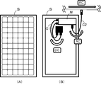
近年、図6に示すように、上記のPCSに代わる太陽電池モジュールSの制御装置として、マイクロインバータMが開発されている。図中、(A)は太陽電池モジュールSの受光側の表面、(B)は裏面である。マイクロインバータMは、太陽電池モジュールS毎に設置され、インバータ機能とMPPT機能を有する小型のPCSである。マイクロインバータMは、各太陽電池モジュールSの裏側又は各太陽電池モジュールSを固定している架台に取り付けられている。なお、マイクロインバータMが太陽電池モジュールSと一体となるように組み付けられた構造のものは、ACモジュールと呼ばれている。
マイクロインバータMの入力側は、直流ケーブルC1を介して、太陽電池モジュールSの出力側に接続されている。また、マイクロインバータMの出力側は、交流ケーブルC2を介して、図示しない系統連系装置等に接続され、この系統連系装置を介して、各マイクロインバータMが系統に連系される。
このようなマイクロインバータMを用いることにより、MPPTを太陽電池モジュールS毎に行い、太陽光発電システム全体の発電量を増加させることができる。また、個々の太陽電池モジュールSの機能低下が、全体の発電量に与える影響を抑えることができる。さらに、太陽光発電システムにおける太陽電池モジュールSの増減変更が容易となる。
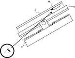
但し、マイクロインバータMも、インバータの一種であることから、目視点検できる必要がある。しかし、マイクロインバータMは、上記のように、各太陽電池モジュールSの裏側に取り付けられているか、各太陽電池モジュールSを屋根Rに取り付けるための架台Bに設置されている。このため、図7に示すように、太陽電池モジュールSを屋根Rに設置した状態では、マイクロインバータMを目視できる隙間は非常に狭く、点検は困難である。
また、マイクロインバータは、一台一台の運転状況等を監視する監視装置に接続され、表示装置を介して運転状況を確認できるように構成されている。そのため、監視装置には、太陽電池モジュールSの設置時に、屋根のどの位置にマイクロインバータを設置したかを示す位置情報が記憶される。しかし、施工者の入力ミスや位置情報の消失が生じると、複数のマイクロインバータから表示装置に表示されているマイクロインバータを特定することが困難となる。したがって、例え表示装置に異常が検出されたマイクロインバータが表示されていたとしても、そのマイクロインバータを探す作業が必要となっていた。
なお、このような課題は、太陽電池モジュールSに個別に接続される監視装置、DC/DCオプティマイザー等の監視又は制御を行う太陽光発電用機器においても同様である。
本発明の実施形態は、上記のような従来技術の問題点を解決するために提案されたものである。その目的は、複数の太陽電池モジュールに個別に接続される太陽光発電用機器であっても、目視による点検や位置の把握がし易い太陽光発電システムを提供することにある。
上記のような目的を達成するため、実施形態の太陽光発電システムは、複数の太陽電池モジュールと、前記太陽電池モジュール毎に個別に接続され、各太陽電池モジュールの制御又は監視を行う複数の太陽光発電用機器と、を有し、前記太陽光発電用機器には、発光体が接続され、前記発光体は、前記太陽電池モジュールの周囲を囲むフレームから突出するように設けられていることを特徴とする。
以下、実施形態に係る太陽光発電システムについて、図面を参照して説明する。
[構成]
図1は、本実施形態の太陽光発電システム100の外観図である。太陽光発電システム100は、太陽光発電により出力した直流電力を、交流電力に変換して宅内の主回路に供給し、あるいは外部の電力系統に逆潮流するシステムである。太陽光発電システム100は、複数の太陽電池モジュール1、複数のマイクロインバータ(以下、MICとする)2を有する。
[構成]
図1は、本実施形態の太陽光発電システム100の外観図である。太陽光発電システム100は、太陽光発電により出力した直流電力を、交流電力に変換して宅内の主回路に供給し、あるいは外部の電力系統に逆潮流するシステムである。太陽光発電システム100は、複数の太陽電池モジュール1、複数のマイクロインバータ(以下、MICとする)2を有する。
(太陽電池モジュール)
太陽電池モジュール1は、受光量を確保するために、太陽光を遮る障害物の少ない場所に設置することが望ましい。そのような設置場所としては、建物の屋根、屋上、上部壁面等が考えられる。あるいは、周囲に大きな建造物のない平野等が考えられる。本実施形態では、図1に示すように、建物の傾斜した屋根Rに設置する例を説明する。
太陽電池モジュール1は、受光量を確保するために、太陽光を遮る障害物の少ない場所に設置することが望ましい。そのような設置場所としては、建物の屋根、屋上、上部壁面等が考えられる。あるいは、周囲に大きな建造物のない平野等が考えられる。本実施形態では、図1に示すように、建物の傾斜した屋根Rに設置する例を説明する。
複数の太陽電池モジュール1は、図1に示すように、隣接して配置されている。複数の太陽電池モジュール1を設置する場合、一般的には、直線状又はマトリクス(行列)状に配置する。図1の例では、12枚の太陽電池モジュール1を、3行×4列で並べて配置している。
太陽電池モジュール1は、屋根Rに架台4により固定されている。架台4としては、種々の構成が適用可能である。図1の例では、棟と平行な柱状の支持部材40が所定の間隔で屋根Rに固定されている。この支持部材40に、太陽電池モジュール1の裏面の両端付近が、図示しない固定金具等により固定されている。同じ行の太陽電池モジュール1は、共通の支持部材40で支持されている。
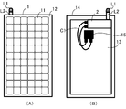
以下、太陽電池モジュール1の具体的な構成を説明する。太陽電池モジュール1は、図2(A)に示すように、複数の太陽電池セル11の集合体を有する。各太陽電池モジュール1における太陽電池セル11は、縦横に複数個配置されている。これらの太陽電池セル11は、受光面側(図2(A))が透明な矩形の支持板12で支持され、反受光面側(図2(B))が矩形のバックシート13で支持されている。
支持板12とバックシート13の周囲は、フレーム14で囲まれている。支持板12とバックシート13との間には、充填材が充填されることにより、太陽電池セル11が封入されている。これにより、太陽電池モジュール1は矩形のパネルとして形成されている。なお、本明細書では、受光面側を表面側とし、反受光面側を裏面側とする。
さらに、太陽電池モジュール1は、図2(B)に示すように、ジャンクションボックス15を備えている。ジャンクションボックス15は、太陽電池モジュール1が発電した直流電力を取り出す端子であり、MIC2との接続のための直流ケーブルC1に接続されている。
(MIC)
複数のMIC2は、上記の太陽電池モジュール1毎に個別に接続される。各MIC2には、図2(A)および(B)に示す通り、発光体L1が接続されている。発光体L1としては、LEDを用いると良い。LEDは複数色での発光が可能なものを用いても良く、例えば赤色と緑色で発光するように構成することができる。図2(B)に示す通り、発光体L1は、太陽電池モジュール1の裏面側にて、MIC2の一側面に支持部材L2を介して接続されている。支持部材L2の長さは適宜設定可能であるが、発光体L1がフレーム14の外側に突出する長さとする。
複数のMIC2は、上記の太陽電池モジュール1毎に個別に接続される。各MIC2には、図2(A)および(B)に示す通り、発光体L1が接続されている。発光体L1としては、LEDを用いると良い。LEDは複数色での発光が可能なものを用いても良く、例えば赤色と緑色で発光するように構成することができる。図2(B)に示す通り、発光体L1は、太陽電池モジュール1の裏面側にて、MIC2の一側面に支持部材L2を介して接続されている。支持部材L2の長さは適宜設定可能であるが、発光体L1がフレーム14の外側に突出する長さとする。
図2(A)に示す通り、発光体L1は、太陽電池モジュール1の表面側においてフレーム14から突出しており、作業者等が視認可能となるように配置されている。なお、発光体L1がフレーム14から突出するように設けられれば、支持部材L2は配置しなくても良い。また、例えばフレーム14に隠れるように発光体L1を設けた場合であっても、発光体L1を移動可能に構成し、フレーム14から突出するように移動させても良い。発光体L1は、MIC2の系統側の制御回路28に接続され、点灯や点滅等の動作が制御されている。以下、制御回路28を含むMIC2の構成について詳細に説明する。
MIC2は、インバータ機能とMPPT機能を有し、太陽電池モジュール1の制御を行う太陽光発電用機器である。インバータ機能は、主として、太陽電池モジュール1からの直流電力を交流電力に変換する機能である。MPPT機能は、最大電力点追従機能を有する。MIC2において各機能を実行する各処理部は、金属の筐体内部に収容されている。MIC2の筐体内部は充填材により封止されている。
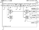
図3に示す通り、MIC2は、フィルタ21、DC/DC変換器22、絶縁トランス23、整流回路24、DC/AC変換器25、およびフィルタ26等の電力変換用の部材を備えている。また、インバータ機能およびMPPT機能を実現する制御回路である、制御回路27,28を有する。
フィルタ21,26は、ノイズ除去用のフィルタである。例えば、フィルタ26は、パルス幅変調制御による高調波を除去する機能を有する。フィルタ21,26は、リアクトルやコンデンサを用いて構成することができる。フィルタ26からの出力側は、配線を介して交流系統に接続されている。DC/DC変換器22は、太陽電池モジュール1から供給された電力を、制御回路27からの制御信号に基づいて所定の電圧の直流電力に変換する変換器である。
絶縁トランス23は、DC/DC変換器22と電力系統の間を絶縁する。整流回路24は、整流素子であるサイリスタとダイオードを含み、DC/DC変換器22の出力電圧を整流する。DC/AC変換器25は、太陽電池モジュール1からの直流電力を、制御回路28からの制御信号に基づいて交流電力に変換する変換器である。
制御回路27は、DC/DC変換器22に接続され、太陽電池モジュール1の出力特性が最大になるように最大電力点追従制御を行うMPPT制御部である。制御回路28は、DC/AC変換器25に接続され、太陽電池モジュール1からの直流電力を交流電力に変換する制御を行うインバータ制御部である。制御回路27,28は、マイクロコントローラ(MCU: micro control unit)で構成することができる。制御回路27,28には、それぞれ制御回路27および28に電力を供給する電源回路37,38が設けられている。
電源回路37は、太陽電池モジュール1から得た直流電力を基に、制御電力を生成する回路である。電源回路37は、フィルタ21を通過した直流電力を取得可能に接続されている。電源回路38は、太陽電池モジュール1から得た直流電力又は電力系統から得た交流電力を基に、制御電力を生成する回路である。電源回路38は、整流回路24を通過した直流電力を取得可能に接続されている。また、電源回路38は、電力系統からの交流電力を取得可能に構成されている。そのため、電源回路38は、電力系統の交流電力を直流電力に変換するためのトランスやAC/DC変換器を含む。
また、制御回路28には、通信部Cと発光体L1が接続されている。制御回路28は、通信部Cおよび発光体L1を制御する機能を有する。通信部Cは、有線又は無線で太陽光発電システム100の遠隔監視装置であるゲートウェイと通信を行う。ゲートウェイは、管理事業者等の操作端末やユーザの操作端末と通信を行う。操作端末からの指示はゲートウェイを介してMIC2に送信され、またMIC2が取得した情報はゲートウェイを介して操作端末に送信される。
制御回路28は、発光体L1を制御する不図示の発光体制御回路を有する。発光体制御回路は、発光体L1の点灯や点滅等の動作を制御する。点灯や点滅の制御は、太陽電池モジュール1やMIC2の制御状態に併せて行うと良い。例えば、操作端末からの点灯指示を通信部Cを介して受信した制御回路28が、発光体L1を点灯させる制御を行う構成とすることができる。
他の例としては、制御回路27が出力した異常信号に基づいて、制御回路28が発光体L1を点灯させる制御を行っても良い。インバータ機能を制御する制御回路27が出力する異常信号に基づいて、発光体L1を点灯することで太陽電池モジュール1の異常を報知する。具体的には、制御回路27が、DC/DC変換器22のスイッチングが停止している場合に、制御回路28に異常信号を出力する場合がある。太陽電池モジュール1側の異常信号を受信した制御回路28は、発光体L1を点滅させるように制御しても良い。
また、点滅速度を調整することにより、複数の異常を報知できる構成とすることができる。例えば、MIC2内の熱センサに異常が生じた場合には所定の速度で点滅を繰り返し、制御回路28と所定の時間以上通信できない場合にはそれよりも速い速度で点滅を繰り返す、等の制御を行っても良い。また、複数色での発光が可能な発光体L1を用いた場合には、発光色により異常を区別することもできる。例えば、制御回路28が、所定の時間以上通信部Cと通信できないことを検出した場合、発光体L1を赤色点灯させる等の制御を行っても良い。
上記の通り発光体L1は、通信部Cを制御する制御回路28に接続されている。この構成は、発光体L1に対する電力の供給をより確実に行うための構成である。MIC2には、制御回路27に電力を供給する電源回路37と、制御回路28に電力を供給する電源回路38が設けられている。制御回路27は、太陽電池モジュール1から得た直流電力を基に動作するため、夜間や異常等により太陽電池モジュール1が発電していない場合には電力を得ることができない。
一方、制御回路28は、太陽電池モジュール1から得た直流電力、または電力系統から得た交流電力を基に動作する。そのため、例え太陽電池モジュール1が発電していない場合であっても、電力系統から電力を得ることができる。以上説明した通り、発光体L1を制御回路28に接続することで、発光体L1は、MIC2のインバータ側と、電力系統側の両方から電力を得る構成となる。
[作用効果]
以上のような本実施形態の作用効果は、以下の通りである。
(1)本実施形態は、複数の太陽電池モジュール1と、太陽電池モジュール1毎に個別に接続され、各太陽電池モジュール1の制御又は監視を行う複数のMIC2と、を有し、MIC2には、発光体L1が接続され、発光体L1は、太陽電池モジュール1の周囲を囲むフレームから突出するように設けられている。
以上のような本実施形態の作用効果は、以下の通りである。
(1)本実施形態は、複数の太陽電池モジュール1と、太陽電池モジュール1毎に個別に接続され、各太陽電池モジュール1の制御又は監視を行う複数のMIC2と、を有し、MIC2には、発光体L1が接続され、発光体L1は、太陽電池モジュール1の周囲を囲むフレームから突出するように設けられている。
このため、複数の太陽電池モジュール1が設置された場合であっても、発光体L1を点灯または点滅させることにより、目視で任意のMIC2を確認することが可能となる。MIC2は、太陽電池モジュール1の裏面側に設置されることが多いが、発光体L1を太陽電池モジュール1のフレームから突出させることで、視認性を向上させることができる。したがって、複数の太陽電池モジュール1に個別に接続される太陽光発電用機器であっても、目視による点検や位置の把握がし易い太陽光発電システム100を提供することができる。
(2)発光体L1は、制御回路28に接続され、制御回路28の電源回路38は、太陽電池モジュール1から得た直流電力又は電力系統から得た交流電力を基に、制御回路28の制御電力を生成する回路である。
発光体L1は、太陽電池モジュール1側の電力と、電力系統側の電力の2種の電力を基に動作させることが可能である。そのため、夜間や異常等により太陽電池モジュール1が発電していない場合には、電力系統側の電力を用いることが可能となる。したがって、発光体L1の点灯等の動作を、太陽電池モジュール1の発電の有無に依存することなく行うことができる。以上より、発光体L1に対する電力の供給をより確実に行うことができる。
また、発光体L1について別途電池等の電力供給源を設けた場合、その電力供給源の寿命がMIC2の寿命より短くなってしまうことが多い。この場合、電力供給源のために保守作業を行う必要が生じてくる。一方、本実施形態の太陽光発電システム100では、太陽電池モジュール1で発電された電力、または電力系統側を流れる電力を用いて発光体L1を動作させる。したがって、発光体L1の電力供給源のために保守作業を行う必要が生じず、効率性が向上される。
(3)発光体L1は、LEDである。
発光体L1としてLEDを用いることで、長寿命でメンテナンス性が高い太陽光発電システム100を提供することができる。また、LEDを用いることで低コスト化も達成できる。LEDは鮮明に発光することから、屋根等の高い位置に太陽電池モジュール1が設置された場合であっても、作業者の視認性が向上する。そのため、保守点検作業の確実性および効率性を向上することが可能となる。
(4)MIC2は、通信部Cをさらに有し、制御回路28は、通信部Cを介して受信した操作端末からの点灯指示に基づいて、発光体L1を点灯させる。
作業者が操作端末から行った、任意の一台のMIC2に対する点灯指示に基づいて、発光体L1を点灯させることができる。そのため、任意の太陽電池モジュール1又はMIC2の位置を瞬時に把握することが可能となる。
(5)制御回路28は、制御回路27が出力した異常信号に基づいて、発光体L1を点灯させる。
インバータ制御部である制御回路27が出力した異常信号に基づいて、発光体L1を制御することにより、MPPT制御側の異常のみならず太陽電池モジュール1側の異常を報知することが可能となる。
[他の実施形態]
(1)本実施形態における発光体L1には、発光体L1を移動させる駆動機構が設けられていても良い。例えば、図4(A)および(B)に示す通り、発光体L1を駆動機構によって起き上がらせる構造とすることができる。この場合には、図4(A)に示す通り、発光体L1を点灯させる必要がない場合には、太陽電池モジュール1のフレーム14の一側面に沿わせるように発光体L1を配置する。一方、発光体L1を点灯させる場合には、駆動機構により発光体L1を回転移動させる。これにより、発光体L1が、太陽電池モジュール1の太陽電池セル11の上面より突出する位置に配置される。したがって、発光体L1の視認性がより向上する。そのため、屋根等の高い位置に設けられた太陽電池モジュール1を、地上からでもより確実に確認することができる。
(1)本実施形態における発光体L1には、発光体L1を移動させる駆動機構が設けられていても良い。例えば、図4(A)および(B)に示す通り、発光体L1を駆動機構によって起き上がらせる構造とすることができる。この場合には、図4(A)に示す通り、発光体L1を点灯させる必要がない場合には、太陽電池モジュール1のフレーム14の一側面に沿わせるように発光体L1を配置する。一方、発光体L1を点灯させる場合には、駆動機構により発光体L1を回転移動させる。これにより、発光体L1が、太陽電池モジュール1の太陽電池セル11の上面より突出する位置に配置される。したがって、発光体L1の視認性がより向上する。そのため、屋根等の高い位置に設けられた太陽電池モジュール1を、地上からでもより確実に確認することができる。
(2)上記の実施形態では、太陽電池モジュール1から得た直流電力又は電力系統から得た交流電力を基に、発光体L1が動作されることで、保守性が向上すると説明した。ただし、実施形態の太陽光発電システム100は、発光体L1に対して電池等の電力供給源を設けることを排除するものではない。電力供給源としては、ボタン電池やセラミックコンデンサを用いることができる。これにより、配線の異常等により、直流電力および交流電力の両方の電力を得ることができなくなった場合であっても、電力供給源により発光体L1を点灯させることが可能となる。
(3)制御回路28またはゲートウェイは、各太陽電池モジュール1と対応する太陽光発電用機器とを、それぞれ識別する識別情報により紐付けた情報を有していても良い。識別情報は、太陽電池モジュール1と太陽光発電用機器のシリアル番号やIDを用いることができる。これにより、作業者は、各MIC2が、どの太陽電池モジュール1を制御しているかを操作端末上で確認できる。したがって、任意の太陽電池モジュール1を選択することにより、当該太陽電池モジュール1のMIC2に接続されている発光体L1を点灯させることができる。よって、太陽電池モジュール1の位置をより確実に把握することができる。
(4)本実施形態における太陽光発電用機器は、MIC2には限定されない。太陽電池モジュール1毎に個別に接続され、各太陽電池モジュール1の制御を行う太陽光発電用機器としては、DC/DCオプティマイザーも含まれる。DC/DCオプティマイザーは、太陽電池モジュール1の出力を一定の電圧に制御する機器である。また、太陽電池モジュール1毎に個別に接続され、各太陽電池モジュール1の監視を行う太陽光発電用機器としては、監視装置も含まれる。監視装置は、太陽電池モジュール1の出力を検出し、表示する機器である。
(5)太陽電池モジュール1は、複数の太陽電池セル11の集合体を広く含み、その名称は問わない。このため、集合体がストリングやアレイ等と呼ばれていても、本実施形態の太陽電池モジュール1として捉えることができる。一般的に太陽電池モジュール1と呼ばれるものを複数接続したものも、本実施形態の太陽電池モジュール1として捉えることもできる。
(6)本発明のいくつかの実施形態を説明したが、これらの実施形態は、例として提示したものであり、発明の範囲を限定することは意図していない。これら実施形態は、その他の様々な形態で実施されることが可能であり、発明の要旨を逸脱しない範囲で、種々の省略、置き換え、変更を行うことができる。これら実施形態やその変形は、発明の範囲や要旨に含まれると同様に、特許請求の範囲に記載された発明とその均等の範囲に含まれるものである。
100 太陽光発電システム
1、S 太陽電池モジュール
2、M マイクロインバータ(MIC)
R 屋根
L1 発光体
L2 支持部材
C1 直流ケーブル
C2 交流ケーブル
11 太陽電池セル
12 支持板
13 バックシート
14 フレーム
15 ジャンクションボックス
21 フィルタ
22 DC/DC変換器
23 絶縁トランス
24 整流回路
25 DC/AC変換器
26 フィルタ
27 制御回路
28 制御回路
37,38 電源回路
C 通信部
1、S 太陽電池モジュール
2、M マイクロインバータ(MIC)
R 屋根
L1 発光体
L2 支持部材
C1 直流ケーブル
C2 交流ケーブル
11 太陽電池セル
12 支持板
13 バックシート
14 フレーム
15 ジャンクションボックス
21 フィルタ
22 DC/DC変換器
23 絶縁トランス
24 整流回路
25 DC/AC変換器
26 フィルタ
27 制御回路
28 制御回路
37,38 電源回路
C 通信部
Claims (7)
- 複数の太陽電池モジュールと、
前記太陽電池モジュール毎に個別に接続され、各太陽電池モジュールの制御又は監視を行う複数の太陽光発電用機器と、
を有し、
前記太陽光発電用機器には、発光体が接続され、
前記発光体は、前記太陽電池モジュールの周囲を囲むフレームから突出するように設けられていることを特徴とする太陽光発電システム。 - 前記発光体には、前記発光体を移動させる駆動回路が設けられていることを特徴とする請求項1記載の太陽光発電システム。
- 前記太陽光発電用機器は、インバータ制御部及びMPPT制御部を有するマイクロインバータであることを特徴とする請求項1又は2記載の太陽光発電システム。
- 前記発光体は、前記MPPT制御部に接続され、
前記MPPT制御部の電源回路は、前記太陽電池モジュールから得た直流電力又は電力系統から得た交流電力を基に、前記MPPT制御部の制御電力を生成する回路であることを特徴とする請求項3記載の太陽光発電システム。 - 前記発光体は、LEDであることを特徴とする請求項1~4いずれか一項記載の太陽光発電システム。
- 前記太陽光発電用機器は、通信部をさらに有し、
前記MPPT制御部は、前記通信部を介して受信した操作端末からの点灯指示に基づいて、発光体を点灯させることを特徴とする請求項1~5いずれか一項記載の太陽光発電システム。 - 前記MPPT制御部は、前記インバータ制御部が出力した異常信号に基づいて、前記発光体を点灯させることを特徴とする請求項1~6いずれか一項記載の太陽光発電システム。
Priority Applications (1)
| Application Number | Priority Date | Filing Date | Title |
|---|---|---|---|
| PCT/JP2015/085917 WO2017109872A1 (ja) | 2015-12-24 | 2015-12-24 | 太陽光発電システム |
Applications Claiming Priority (1)
| Application Number | Priority Date | Filing Date | Title |
|---|---|---|---|
| PCT/JP2015/085917 WO2017109872A1 (ja) | 2015-12-24 | 2015-12-24 | 太陽光発電システム |
Publications (1)
| Publication Number | Publication Date |
|---|---|
| WO2017109872A1 true WO2017109872A1 (ja) | 2017-06-29 |
Family
ID=59090962
Family Applications (1)
| Application Number | Title | Priority Date | Filing Date |
|---|---|---|---|
| PCT/JP2015/085917 Ceased WO2017109872A1 (ja) | 2015-12-24 | 2015-12-24 | 太陽光発電システム |
Country Status (1)
| Country | Link |
|---|---|
| WO (1) | WO2017109872A1 (ja) |
Citations (4)
| Publication number | Priority date | Publication date | Assignee | Title |
|---|---|---|---|---|
| JPS59224890A (ja) * | 1983-06-06 | 1984-12-17 | 本田技研工業株式会社 | 車両用表示装置 |
| JP2002112459A (ja) * | 2000-09-29 | 2002-04-12 | Canon Inc | 太陽電池モジュールおよび発電装置 |
| JP2013110290A (ja) * | 2011-11-22 | 2013-06-06 | Toshiba Corp | 太陽光発電システム及びその故障表示装置 |
| JP2015198508A (ja) * | 2014-04-01 | 2015-11-09 | 株式会社東芝 | 太陽光発電装置 |
-
2015
- 2015-12-24 WO PCT/JP2015/085917 patent/WO2017109872A1/ja not_active Ceased
Patent Citations (4)
| Publication number | Priority date | Publication date | Assignee | Title |
|---|---|---|---|---|
| JPS59224890A (ja) * | 1983-06-06 | 1984-12-17 | 本田技研工業株式会社 | 車両用表示装置 |
| JP2002112459A (ja) * | 2000-09-29 | 2002-04-12 | Canon Inc | 太陽電池モジュールおよび発電装置 |
| JP2013110290A (ja) * | 2011-11-22 | 2013-06-06 | Toshiba Corp | 太陽光発電システム及びその故障表示装置 |
| JP2015198508A (ja) * | 2014-04-01 | 2015-11-09 | 株式会社東芝 | 太陽光発電装置 |
Similar Documents
| Publication | Publication Date | Title |
|---|---|---|
| CN106687933B (zh) | 用于紧急出口的系统和方法及监测系统 | |
| US9647459B2 (en) | Distributed low voltage power systems | |
| US20130328404A1 (en) | Voltage conversion apparatus, power generation system, and voltage conversion method | |
| JP6642400B2 (ja) | 光検知装置及び設備管理システム | |
| EP2003393B1 (en) | Daylight reflecting artificial light | |
| CN101694276B (zh) | 一种led路灯系统 | |
| US20180278203A1 (en) | Modular solar power generation apparatus | |
| JP6621034B2 (ja) | シグナルタワー点灯検知方法及び装置 | |
| KR101360401B1 (ko) | 자기진단 기능을 구비한 태양광 발전시스템 | |
| WO2017109872A1 (ja) | 太陽光発電システム | |
| KR20130005979A (ko) | 태양광발전장치의 통합관리시스템 | |
| KR101589877B1 (ko) | 광대역 통신망을 이용한 태양광 모니터링 시스템 | |
| JP5153722B2 (ja) | 光電変換装置 | |
| WO2025179908A1 (zh) | 一种表示器模块、工作方法及检测方法 | |
| JP2011153927A (ja) | 電線の加圧状態表示装置 | |
| JP2016111849A (ja) | 太陽電池モジュール、太陽光発電システム、及び太陽電池モジュール用端子箱 | |
| CN211237071U (zh) | 一种电力设备工作异常警示装置 | |
| KR101208810B1 (ko) | 건물일체형 태양광발전시스템 및 그것의 태양광 모듈 자체 진단 방법 | |
| WO2017109871A1 (ja) | 太陽光発電システム及び太陽光発電用機器の支持装置 | |
| KR20110133362A (ko) | 고압 선로 인식 led 항공장애등 | |
| JP2016100991A (ja) | 発電システム | |
| KR200460392Y1 (ko) | 태양광모듈용 공용접속반 | |
| KR102699194B1 (ko) | 태양광가로등의 시험장치 | |
| KR20130041874A (ko) | 조명 제어 장치 | |
| CN104656538A (zh) | 一种智能光伏发电监控箱 |
Legal Events
| Date | Code | Title | Description |
|---|---|---|---|
| 121 | Ep: the epo has been informed by wipo that ep was designated in this application |
Ref document number: 15911310 Country of ref document: EP Kind code of ref document: A1 |
|
| NENP | Non-entry into the national phase |
Ref country code: DE |
|
| 122 | Ep: pct application non-entry in european phase |
Ref document number: 15911310 Country of ref document: EP Kind code of ref document: A1 |
|
| NENP | Non-entry into the national phase |
Ref country code: JP |