WO2017107002A1 - Procédé et dispositif pour une formation de faisceau - Google Patents
Procédé et dispositif pour une formation de faisceau Download PDFInfo
- Publication number
- WO2017107002A1 WO2017107002A1 PCT/CN2015/098047 CN2015098047W WO2017107002A1 WO 2017107002 A1 WO2017107002 A1 WO 2017107002A1 CN 2015098047 W CN2015098047 W CN 2015098047W WO 2017107002 A1 WO2017107002 A1 WO 2017107002A1
- Authority
- WO
- WIPO (PCT)
- Prior art keywords
- layer
- precoding matrix
- layer precoding
- user equipment
- determining
- Prior art date
Links
Images


Classifications
-
- H—ELECTRICITY
- H04—ELECTRIC COMMUNICATION TECHNIQUE
- H04B—TRANSMISSION
- H04B7/00—Radio transmission systems, i.e. using radiation field
- H04B7/02—Diversity systems; Multi-antenna system, i.e. transmission or reception using multiple antennas
- H04B7/04—Diversity systems; Multi-antenna system, i.e. transmission or reception using multiple antennas using two or more spaced independent antennas
- H04B7/0413—MIMO systems
- H04B7/0456—Selection of precoding matrices or codebooks, e.g. using matrices antenna weighting
- H04B7/046—Selection of precoding matrices or codebooks, e.g. using matrices antenna weighting taking physical layer constraints into account
- H04B7/0465—Selection of precoding matrices or codebooks, e.g. using matrices antenna weighting taking physical layer constraints into account taking power constraints at power amplifier or emission constraints, e.g. constant modulus, into account
-
- H—ELECTRICITY
- H04—ELECTRIC COMMUNICATION TECHNIQUE
- H04B—TRANSMISSION
- H04B7/00—Radio transmission systems, i.e. using radiation field
- H04B7/02—Diversity systems; Multi-antenna system, i.e. transmission or reception using multiple antennas
- H04B7/04—Diversity systems; Multi-antenna system, i.e. transmission or reception using multiple antennas using two or more spaced independent antennas
- H04B7/0413—MIMO systems
- H04B7/0456—Selection of precoding matrices or codebooks, e.g. using matrices antenna weighting
-
- H—ELECTRICITY
- H04—ELECTRIC COMMUNICATION TECHNIQUE
- H04B—TRANSMISSION
- H04B17/00—Monitoring; Testing
- H04B17/30—Monitoring; Testing of propagation channels
- H04B17/309—Measuring or estimating channel quality parameters
-
- H—ELECTRICITY
- H04—ELECTRIC COMMUNICATION TECHNIQUE
- H04B—TRANSMISSION
- H04B7/00—Radio transmission systems, i.e. using radiation field
- H04B7/02—Diversity systems; Multi-antenna system, i.e. transmission or reception using multiple antennas
- H04B7/04—Diversity systems; Multi-antenna system, i.e. transmission or reception using multiple antennas using two or more spaced independent antennas
- H04B7/06—Diversity systems; Multi-antenna system, i.e. transmission or reception using multiple antennas using two or more spaced independent antennas at the transmitting station
- H04B7/0613—Diversity systems; Multi-antenna system, i.e. transmission or reception using multiple antennas using two or more spaced independent antennas at the transmitting station using simultaneous transmission
- H04B7/0615—Diversity systems; Multi-antenna system, i.e. transmission or reception using multiple antennas using two or more spaced independent antennas at the transmitting station using simultaneous transmission of weighted versions of same signal
- H04B7/0619—Diversity systems; Multi-antenna system, i.e. transmission or reception using multiple antennas using two or more spaced independent antennas at the transmitting station using simultaneous transmission of weighted versions of same signal using feedback from receiving side
- H04B7/0636—Feedback format
- H04B7/0645—Variable feedback
- H04B7/065—Variable contents, e.g. long-term or short-short
Definitions
- the present disclosure relates to wireless communication systems, and more particularly to the precoding of data to be transmitted in a Multiple-input Multiple-output (MIMO) wireless communication system. More precisely, the present disclosure aims at providing a precoding solution for very large MIMO systems known as “Massive MIMO systems” .
- MIMO Massive Multiple-Input and Multiple-Output
- Massive MIMO systems also known as Large-Scale Antenna Systems, Very Large MIMO, Hyper MIMO, Full-Dimension MIMO and ARGOS
- a base station is equipped with a very large number of antennas (e.g., hundreds or thousands) that are operated fully coherently and adaptively according to a multi-user MIMO scheme.
- inter-cell interference (ICI) and intra-cell interferences degrades the performance of massive MIMO system.
- ICI inter-cell interference
- the reduction of inter-cell interference (ICI) can be achieved by using properly configured precoders at the transmitter side (i.e. at the side of at least one base station) , in other words by choosing carefully beamforming vectors, or precoding weights, before the transmission of the signal to multiple users.
- the coordinated beamforming requires only a modest amount of signaling overhead and, for the sake of implementation, is classically proposed to improve system performance.
- each evolved Node B consists of two layers: on the one hand a first precoder, called a “cell-layer precoder” in the following of the disclosure, and a second precoder, called a “user-layer precoder” on the other hand.
- the user-layer precoder supports data transmission to the active user terminal (UEs) by exploiting the knowledge of the time-variant channel state information (CSI) .
- CSI channel state information
- the cell-layer precoder exploits the remaining spatial degree of freedom for mitigating the ICI by relying only on the knowledge of the long-term variant channel state information (CSI) .
- the cell-layer precoder of existing hierarchical-structure coordinated beamforming (CBF) schemes is adjusted to reduce Inter-Cell Interference with low complexity
- the user-layer precoder of the prior art is settled as ZF precoder, and considers power allocation issue in precoding, which may result in more intra-cell interference.
- the present disclosure proposes a method for transmitting a signal carrying data from a network equipment to a user equipment in a multiple input-multiple output (MIMO) communication system, said method optimizing the beamforming approach for the precoding scheme.
- MIMO multiple input-multiple output
- the method comprises applying a double-layer coordinated beamforming of the data prior to their transmission to the user equipment; the double-layer coordinated beamforming comprising:
- Such determining of the second layer precoding matrix is optimized by using a predetermined signal-to-interference-plus-noise ratio of the signal, and/or a predetermined power value associated with a single antenna of the user equipment, as optimization parameters.
- the present disclosure thus relies on a novel and inventive approach for beamforming by proposing a double layer coordinated beamforming minimizing the total power consumption of the considered network equipment (corresponding to an evolve node B or more generally a base station BS) , while guaranteeing the required data rate of each User Equipment and satisfying the power constraint of single antenna.
- the present disclosure permits essentially to enhance the coordinated beamforming of the prior art by adding some constraints during the optimization of the second layer precoding.
- first layer precoding is called “cell-layer precoding” whereas “second layer precoding” is called “user-layer precoding” .
- the cell-layer precoding is adjusted to reduce the Inter-cell Interference
- the cell-layer precoding obtained by the network equipment according to the present disclosure is not use to settle the user-layer precoding as a ZF precoder.
- the provided cell-layer precoding is used in combination with the value of the targeted signal-to interference-plus-noise ratio and/or with the power of the single antenna of a user equipment depending on the considered network equipment, for optimising the user-layer precoding.
- At least one constraint is additionally directly taken into account as a parameter for obtaining at least one user-layer precoding vector of second layer precoding matrix called user-layer precoding matrix in the following.
- the proposed scheme significantly increases the signal-to-interference-plus-noise ratio of cell-edge user equipment and reduces the system energy efficiency with low signalling overhead compared with the techniques of the prior art corresponding to the ZF and cluster coordinated multi-point (CoMP) schemes.
- the real-time channel state information is obtained at each time slot.
- the determining of the second layer precoding matrix is iterative until convergence and comprises for each iteration:
- the optimizing implements an iterative algorithm based on the use of two Lagrange multipliers, which are respectively optimized using on the one hand the predetermined signal-to-interference-plus-noise ratio, and on the other hand the predetermined power value.
- this embodiment is based on the application of two constraints for optimizing two distinct Lagrange multipliers permitting to obtain an associated optimal user-layer precoding vector.
- the value of the first Lagrange multiplier associated with the second layer precoding is determined by using a second layer precoding sub-gradient projection.
- the present disclosure further proposes a network equipment for transmitting a signal carrying data to a user equipment in a multiple-input multiple-output communication system, the network equipment being adapted to perform a double-layer coordinated beamforming of the data prior to their transmission to the user equipment; the network equipment comprising:
- -a receiver connected to a plurality of antennas, and configured to receive a first layer precoding matrix obtained from long-term channel state information between the user equipment and the network equipment, and
- -a precoding module connected to the receiver, and configured to determine a second layer precoding matrix obtained from the first layer precoding matrix and from real-time channel state information between the user equipment and the network equipment,
- -a double-layer coordinated beamforming module connected to the receiver and to the precoding module, configured to combine the first layer precoding matrix and the second layer precoding matrix.
- the double-layer coordinated beamforming module determining the second layer precoding matrix, is optimized by using a predetermined signal-to-interference-plus-noise ratio of the signal, and/or a predetermined power value associated with a single antenna of the user equipment, as optimization parameters.
- Such a network equipment corresponding to an evolved Node B or more generally a base station is particularly adapted to implement the method for transmitting a signal carrying data from a network equipment to a user equipment in a multiple-input multiple-output communication system as described above.
- Such a network equipment could of course comprise the different characteristics pertaining to the method of for transmitting a signal carrying data from a network equipment to a user equipment in a multiple-input multiple-output communication system.
- the features and advantages of this network equipment are the same as those of the method of for transmitting a signal carrying data from a network equipment to a user equipment in a multiple-input multiple-output communication system according to the present application, and is not described in more detail.
- the disclosure further relates to a multiple-input multiple-output communication system comprising:
- central equipment configured to determine a first layer precoding matrix (F) from at least long-term channel state information between the at least one user equipment and the at least one network equipment.
- F first layer precoding matrix
- Such a user equipment is for example a mobile phone
- the central equipment is for example an evolved Node B selected among the other evolved Nodes B of a network comprising a plurality of cells.
- the central equipment comprises a module for obtaining iteratively the first layer precoding matrix, the module for obtaining comprising the following means implemented for each iteration:
- the means for determining a value for each of the two first layer precoding Lagrange multipliers for the next iteration comprises means for performing a first layer precoding sub-gradient projection obtaining simultaneously the two first layer precoding Lagrange multipliers.
- the central equipment comprises means for initializing the threshold as a mean of a lower bound and an upper bound of inter-cell interference, said upper bound being proportional to a predetermined power value Pant associated with a single antenna of said user equipment UE.
- the object of the present disclosure uses the expression of the inter-cell interference and of the signal-to-interference-plus-noise ratio to optimize the proposed double-layer coordinated beamforming.
- Such a use imposes vast overhead among the network equipments of the considered massive MIMO system.
- Setting the upper bound, of the threshold used during the obtaining of the first layer precoding, as being proportional to a predetermined power value associated with a single antenna of said user equipment permits to overcome such a vast overhead.
- the disclosure also relates to computer program comprising instruction codes for implementing the method for transmitting a signal carrying data according to present disclosure, when loaded and run on processing means of a network equipment.
- Such a computer program is a non-transitory computer-readable medium.
- aspects of the present principles can take the form of an entirely hardware embodiment, an entirely software embodiment, or an embodiment combining software and hardware aspects.
- aspects of the present principles can take the form of a computer readable storage medium. Any combination of one or more computer readable storage medium (s) may be utilized.
- - Figure 2 represents the vector transmission channel established between a network equipment and a user equipment
- - Figure 5 represents a network equipment capable of running the method of transmission of the present disclosure.
- the general principle of the present disclosure consists in a new way of beamforming a signal carrying data implemented by a network equipment prior to its transmission to a user equipment, by applying a double-layer coordinated beamforming whose second layer is optimized, in a network equipment associated with a cell, according to the present disclosure by taking into account the result provided by the first layer and by taking into account at least one constraint among a predetermined signal-to-interference-plus-noise ratio of said signal, and/or a predetermined power value associated with a single antenna of a user equipment.
- FIG. 1 The application environment of the transmitting method according to the present disclosure is illustrated by figure 1. More precisely, a multi-user system is considered in a multi-cell scenario.
- each cell (C 1 , C 2 , C 3 ) is settled one network equipment corresponding to a base station, which is for example an evolved Node B (eNB 1 , eNB 2 , eNB 3 ) .
- a base station which is for example an evolved Node B (eNB 1 , eNB 2 , eNB 3 ) .
- K User Equipments are served by each of the L cells (for simplicity, only one User Equipment (UE) is however represented on figure 1) .
- each user equipment comprises a single antenna whose maximum power is P ant .
- T denotes a matrix transposition, transforming row vector to column vector
- diag (a) represents a diagonal matrix whose diagonal elements are the elements of vector a ,
- eNB network equipment
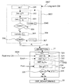
- Figure 3A illustrates the main steps of the transmitting method according to the present disclosure.
- Such a method corresponds to a double-layer precoding wherein, when considering the i-th cell among the set of L involved cell, a first layer precoding matrix F i is first provided by a first precoding layer called “Cell-layer beamforming” 3001, and a second layer precoding matrix W i is provided by a second precoding layer called “User-layer beamforming” 3002 and is used for serving the user equipments in a same cell i.
- a first layer precoding matrix F i is first provided by a first precoding layer called “Cell-layer beamforming” 3001
- a second layer precoding matrix W i is provided by a second precoding layer called “User-layer beamforming” 3002 and is used for serving the user equipments in a same cell i.
- the beamforming matrix V i is partitioned into:
- V i F i W i .
- the cell-layer precoder obtained by a central node for all eNB is used to obtain the spatial multiplexing gain for mitigating inter-cell interference (ICI) among cells. Meanwhile, the user-layer precoder supports the data transmission by exploiting the local instantaneous channel state information in each cell.
- ICI inter-cell interference
- one of the network equipments (i.e. eNB) of the massive MIMO communication system is classically chosen as a central equip (i.e. central controller) to perform the Cell-layer precoding 3001 as represented in dotted lines in figure 3B.
- said network equipment of the j-th adjacent cell estimates the corresponding spatial correlation matrix R i, jk of the communication channel between the considered k-th user equipment in the j-th cell and the i-th cell.
- said spatial correlation matrix represents long-term channel state information (long-term CSI) 3005 between each adjacent cell user interfered by the i-th cell,
- each network equipment (i.e. eNB) of the scheme according to the present disclosure only need to sens spatial correlation matrices of User equipments to the central node, which significantly reduces channel state information signalling overhead.
- the corresponding spatial correlation matrices R i, jk of channel vectors change slower than the real-time channel state information (CSI) .
- CSI channel state information
- said central equipment comprises a module for obtaining iteratively first layer precoding matrices for each involved eNB.
- said module for obtaining comprising the following means implemented for each iteration:
- n the number of iterations
- n the number of iterations
- two threshold values corresponding to two threshold bounds and used for ending the processing
- Such initialization of the obtaining of the cell-layer beamforming matrix according to the present disclosure is used to limit the overhead among eNBs managed by said central equipment when mitigating the inter-cell interference of each eNB with the cell-layer precoding.
- the “effective channel” of each cell is nearly orthogonal, which can be denoted as
- the cell layer precoder is obtained by solving the following problem as implemented by the obtaining module of the central node:
- the epigraph form of this problem is expressed as:
- Such an epigraph form of problem with fixed ⁇ is a convex problem and a bisection method to find optimal ⁇ * of ⁇ can then be used.
- the corresponding threshold ⁇ (n) is obtained such as and determining (302) at least one eigen-vector of said first layer precoding matrix is performed.
- said at least one eigen-vector corresponds to the negative eigenvalues of the matrix
- ⁇ is a constant and satisfies K ⁇ K ⁇ M and ensures that after cell-layer precoding the eNBs still have enough degree of spatial freedom for serving a user equipment.
- the absolute difference between the two threshold bounds is computed and compared (306) to a tolerable error ⁇ .
- the central node After obtaining said cell-layer precoding matrix F i with with D i the degree of spatial freedom for the it-th cell, the central node sends it to the i-th eNB, which receives (31) it can then obtain (321) the matrix as an effective channel where H i is a real time channel state information sends (3006) by each user equipment in the i-th cell at each time slot.
- an initialisation (320) is performed by said network equipment eNB i .
- ⁇ ik is the SINR value for the considered k-th user equipment
- At least one vector associated with said second layer precoding matrix is obtained (323) as following:
- ⁇ i [ ⁇ i, 1 , ⁇ i, 2 , ..., ⁇ i, K ] T and where ⁇ 2 is the power of additive white Gaussian noise, cell interference from the j-th eNB to the k-th user equipment in the i-th cell such that as well as the elements of the matrix T i ⁇ C K ⁇ K are given by :
- the user-layer precoding matrix and power allocation scheme is obtained as following: else p the number of iteration is incremented (326) and the steps (321, 322, 323, 324) of the determining 3002 of a second layer precoding matrix are reiterated until convergence (325) .
- the scheme proposed according to the present disclosure can minimize the total transmit power across all eNBs, which namely improves the system energy efficiency while guaranteeing the targeted SINR of each user equipment. Moreover, the power constraint of single antenna is considered, which improves the efficiency of power amplifier of each user equipment.
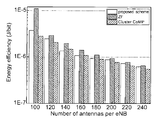
- Figure 4A to 4C represent a comparison between the results obtained according to the present disclosure and the results obtained using the prior art techniques.
- figure 4A represents the average signal-to-interference-plus-noise ratio (SINR) of a user equipment as a function of an increasing number of transmit antennas per network equipment (eNB) .
- SINR signal-to-interference-plus-noise ratio
- the average downlink SINR per user equipment (UE) of the proposed scheme guarantees the target SINR (10 dB) compared with other schemes of the prior art including the cell ZF beamforming and the coordinated multipoint (CoMP) transmission.
- Figure 4B represents the downlink SINR of cell-edge User equipment, SINR of cell-edge User equipment being defined as the 5 th percentile point of a cumulative distribution function of the user equipment’s SINR.
- the cell-edge user equipment SINR obtained according to the proposed method outperforms other schemes as the cell-layer precoder mitigates the inter-cell interference.
- Figure 4C represents the obtained energy efficiency according to the proposed scheme. It can be seen, that the present disclosure permits to reach an energy efficiency, which is slightly larger than the one obtained using the coordinated multipoint (CoMP) transmission. It has to be noted that in the cluster (CoMP) scheme, network equipments (eNBs) in the same cluster serve the same user equipment (UE) , thus each eNB need less power compared to the proposed scheme.
- CoMP cluster
- the cluster (CoMP) scheme needs the instantaneous channel state information (like in the present disclosure) , but also the data information of the target user equipments to be shared among the eNBs in the same cluster, which will consume overwhelming overhead resources compared to the proposed scheme, which does not require such data information.
- figure 5 illustrates the simplified structure of network equipment (eNB) implementing or being used for implementing a method for transmitting a signal as described here above.
- eNB network equipment
- a network equipment as illustrated in figure 5, comprises a memory 51 comprising a buffer memory, a processing unit 52 equipped for example with a microprocessor ⁇ P and driven by the computer program 53, implementing the method for performing for transmitting a signal according to the present disclosure.
- the code instructions of the computer program 53 are for example loaded into a RAM and then executed by the processor of the processing unit 52.
- the microprocessor of the processing unit 52 implements the steps of the method for transmitting a signal as described here above according to the computer program instructions 53.
- the network equipment comprises, in addition to the buffer memory 51, a receiver, connected to a plurality of antennas, and configured to receive a first layer precoding matrix (F) obtained from long-term channel state information between a user equipment and said network equipment, a precoding module, connected to said receiver, and configured to determine a second layer precoding matrix (W) obtained from said first layer precoding matrix and from real-time channel state information (H i ) between said user equipment and said network equipment, adouble-layer coordinated beamforming (V) module, connected to the receiver and to the precoding module, configured to combine said first layer precoding matrix (F) and said second layer precoding matrix (W) , said double-layer coordinated beamforming (V) module, determining said second layer precoding matrix (W) , being optimized by using a predetermined signal-to-interference-plus-noise ratio (SINR) of said signal, and/or a predetermined power value (Pant) associated with a single antenna of said user equipment (UE) ,
- SINR signal-to-
Abstract
L'invention concerne un procédé pour émettre un signal transportant des données dans un système de communication à entrées multiples, sorties multiples (MIMO), ledit procédé consistant à appliquer une formation de faisceau coordonnée à double couche consistant : - à recevoir (31) une matrice de précodage de première couche (F) obtenue au moins à partir d'informations d'état de canal à long terme entre ledit équipement utilisateur et ledit équipement de réseau, et – à déterminer (3002) une matrice de précodage de seconde couche (W) obtenue à partir de ladite matrice de précodage de première couche et à partir d'informations d'état de canal en temps réel (Hi) entre ledit équipement utilisateur et ledit équipement de réseau, - à obtenir (33) ladite formation de faisceau coordonnée à double couche (V) par combinaison de ladite matrice de précodage de première couche (F) et de ladite matrice de précodage de seconde couche (W). Selon la présente invention, la détermination de ladite matrice de précodage de seconde couche (W) est optimisée en utilisant un rapport signal sur brouillage plus bruit (SINR) prédéterminé dudit signal, et/ou une valeur de puissance prédéterminée (Pant) associée à une antenne unique dudit équipement utilisateur (UE), comme paramètres d'optimisation.
Priority Applications (3)
| Application Number | Priority Date | Filing Date | Title |
|---|---|---|---|
| PCT/CN2015/098047 WO2017107002A1 (fr) | 2015-12-21 | 2015-12-21 | Procédé et dispositif pour une formation de faisceau |
| EP16200601.9A EP3185434B8 (fr) | 2015-12-21 | 2016-11-24 | Procédé et dispositif formation de faisceau |
| US15/385,839 US10666329B2 (en) | 2015-12-21 | 2016-12-20 | Method and device for beam forming |
Applications Claiming Priority (1)
| Application Number | Priority Date | Filing Date | Title |
|---|---|---|---|
| PCT/CN2015/098047 WO2017107002A1 (fr) | 2015-12-21 | 2015-12-21 | Procédé et dispositif pour une formation de faisceau |
Publications (1)
| Publication Number | Publication Date |
|---|---|
| WO2017107002A1 true WO2017107002A1 (fr) | 2017-06-29 |
Family
ID=57394495
Family Applications (1)
| Application Number | Title | Priority Date | Filing Date |
|---|---|---|---|
| PCT/CN2015/098047 WO2017107002A1 (fr) | 2015-12-21 | 2015-12-21 | Procédé et dispositif pour une formation de faisceau |
Country Status (3)
| Country | Link |
|---|---|
| US (1) | US10666329B2 (fr) |
| EP (1) | EP3185434B8 (fr) |
| WO (1) | WO2017107002A1 (fr) |
Cited By (1)
| Publication number | Priority date | Publication date | Assignee | Title |
|---|---|---|---|---|
| US10666329B2 (en) * | 2015-12-21 | 2020-05-26 | Orange | Method and device for beam forming |
Families Citing this family (6)
| Publication number | Priority date | Publication date | Assignee | Title |
|---|---|---|---|---|
| CN107395259B (zh) * | 2016-05-13 | 2020-04-21 | 华为技术有限公司 | 一种二级预编码方法及装置 |
| EP3522404B1 (fr) * | 2018-02-02 | 2021-04-21 | Mitsubishi Electric R&D Centre Europe B.V. | Identification d'interférences wifi pour une utilisation dans un système à sauts de fréquence public |
| CN111181612B (zh) * | 2019-12-31 | 2021-03-30 | 内蒙古大学 | 一种大规模mimo系统的协作波束赋型方法 |
| CN112702091B (zh) * | 2020-12-22 | 2022-01-14 | 杭州电子科技大学 | 多用户多天线swipt中改进的max-sinr干扰对齐方法 |
| CN117674920A (zh) * | 2022-08-12 | 2024-03-08 | 华为技术有限公司 | 上行传输的方法和装置 |
| CN116633399B (zh) * | 2023-07-20 | 2023-11-03 | 深圳市大数据研究院 | 语义通信波形设计方法、装置、设备和存储介质 |
Citations (3)
| Publication number | Priority date | Publication date | Assignee | Title |
|---|---|---|---|---|
| CN102624496A (zh) * | 2011-01-30 | 2012-08-01 | 华为技术有限公司 | 预编码处理方法、基站和通信系统 |
| CN104065448A (zh) * | 2013-03-22 | 2014-09-24 | 电信科学技术研究院 | 一种确定预编码矩阵的方法、系统和设备 |
| WO2015094661A1 (fr) * | 2013-12-18 | 2015-06-25 | Intel Corporation | Équipement utilisateur et procédé de précodage pour mise en forme de faisceaux basée sur un livre de codes mimo utilisant une matrice d'autocorrélation pour réduire un bruit de quantification |
Family Cites Families (27)
| Publication number | Priority date | Publication date | Assignee | Title |
|---|---|---|---|---|
| US8363744B2 (en) * | 2001-06-10 | 2013-01-29 | Aloft Media, Llc | Method and system for robust, secure, and high-efficiency voice and packet transmission over ad-hoc, mesh, and MIMO communication networks |
| US8797950B2 (en) * | 2009-05-27 | 2014-08-05 | Texas Instruments Incorporated | Dual-layer beam forming in cellular networks |
| WO2010148119A2 (fr) * | 2009-06-19 | 2010-12-23 | Research In Motion Limited | Signal de référence de liaison descendante pour relais de type ii |
| US8711716B2 (en) * | 2009-06-19 | 2014-04-29 | Texas Instruments Incorporated | Multiple CQI feedback for cellular networks |
| US8750205B2 (en) * | 2009-08-07 | 2014-06-10 | Texas Instruments Incorporated | Multiple rank CQI feedback for cellular networks |
| US9351293B2 (en) * | 2009-09-11 | 2016-05-24 | Qualcomm Incorporated | Multiple carrier indication and downlink control information interaction |
| EP2497215B1 (fr) * | 2009-11-06 | 2019-07-03 | LG Electronics Inc. | Procédé de regroupement de blocs de ressource (rb) |
| EP2507960B1 (fr) * | 2009-12-04 | 2018-06-06 | Telefonaktiebolaget LM Ericsson (publ) | Appareil et procédé pour l'estimation de canal dans un système de communication sans fil |
| US9762372B2 (en) * | 2010-06-15 | 2017-09-12 | Texas Instruments Incorporated | CSI reporting on PUSCH for carrier aggregation |
| EP2625884B1 (fr) * | 2010-10-08 | 2020-07-15 | BlackBerry Limited | Procédé et appareil pour l'estimation de données d'état de canal lte |
| CN103222296B (zh) * | 2010-11-22 | 2016-08-10 | 诺基亚通信公司 | 利用部分信道状态信息的多层波束成形 |
| US20120182895A1 (en) * | 2011-01-13 | 2012-07-19 | Electronics And Telecommunications Research Institute | Apparatus and method for transmitting and receiving channel state information |
| KR101806311B1 (ko) * | 2011-03-04 | 2017-12-07 | 삼성전자주식회사 | 규준화된 빔포밍을 사용하는 네트워크 다중 입출력 통신 시스템 |
| CN103404052B (zh) * | 2011-03-10 | 2015-09-23 | 富士通株式会社 | 干扰协调方法、基站和用户设备 |
| WO2012148478A1 (fr) * | 2011-04-29 | 2012-11-01 | Intel Corporation | Technologie permettant une rétroaction de csi dans un système de communication mimo |
| US9160425B2 (en) * | 2011-07-01 | 2015-10-13 | Telefonaktiebolaget L M Ericsson (Publ) | Beamforming with phase compensation |
| US9137818B2 (en) * | 2011-12-14 | 2015-09-15 | Alcatel Lucent | Method and system for a reduced-complexity scheduling for a network MIMO with linear zero-forcing beamforming |
| US20130331136A1 (en) * | 2012-06-07 | 2013-12-12 | Kai Yang | Method And Apparatus For Coordinated Beamforming |
| CN103634036B (zh) * | 2012-08-27 | 2017-10-27 | 华为技术有限公司 | 分布式多小区多用户波束成形方法、发射机及相关系统 |
| EP2975779B1 (fr) * | 2013-03-11 | 2018-07-25 | LG Electronics Inc. | Procédé et appareil de rapport d'informations d'état de canal dans un système de communication sans fil |
| US9590744B2 (en) * | 2013-05-06 | 2017-03-07 | Alcatel Lucent | Method and apparatus for beamforming |
| EP2997688B1 (fr) * | 2013-05-16 | 2018-08-08 | Telefonaktiebolaget LM Ericsson (publ) | Procédé et appareil de prise de contrôle de rang |
| US9450657B2 (en) * | 2013-08-28 | 2016-09-20 | Nec Corporation | Low-complexity precoder design for large-scale MIMO communication systems |
| WO2015033661A1 (fr) * | 2013-09-03 | 2015-03-12 | ソニー株式会社 | Appareil de commande de communication, procédé de commande de communication et appareil terminal |
| CN103905105B (zh) * | 2014-02-19 | 2017-10-03 | 大唐移动通信设备有限公司 | 一种双流波束赋形方法和装置 |
| US10263670B2 (en) * | 2016-07-21 | 2019-04-16 | NxGen Parners IP, LLC | System and method for reducing pilot signal contamination using orthogonal pilot signals |
| WO2017107002A1 (fr) * | 2015-12-21 | 2017-06-29 | Orange | Procédé et dispositif pour une formation de faisceau |
-
2015
- 2015-12-21 WO PCT/CN2015/098047 patent/WO2017107002A1/fr active Application Filing
-
2016
- 2016-11-24 EP EP16200601.9A patent/EP3185434B8/fr active Active
- 2016-12-20 US US15/385,839 patent/US10666329B2/en active Active
Patent Citations (3)
| Publication number | Priority date | Publication date | Assignee | Title |
|---|---|---|---|---|
| CN102624496A (zh) * | 2011-01-30 | 2012-08-01 | 华为技术有限公司 | 预编码处理方法、基站和通信系统 |
| CN104065448A (zh) * | 2013-03-22 | 2014-09-24 | 电信科学技术研究院 | 一种确定预编码矩阵的方法、系统和设备 |
| WO2015094661A1 (fr) * | 2013-12-18 | 2015-06-25 | Intel Corporation | Équipement utilisateur et procédé de précodage pour mise en forme de faisceaux basée sur un livre de codes mimo utilisant une matrice d'autocorrélation pour réduire un bruit de quantification |
Non-Patent Citations (1)
| Title |
|---|
| ROYA DOOSTNEJAD.: "Precoding and Beamforming for Multi-Input Multi-Output Downlink Channels", A THESIS SUBMITTED IN CONFORMITY WITH THE REQUIREMENTS FOR THE DEGREE OF DOCTOR OF PHILOSOPHY, 31 December 2005 (2005-12-31), XP055395488 * |
Cited By (1)
| Publication number | Priority date | Publication date | Assignee | Title |
|---|---|---|---|---|
| US10666329B2 (en) * | 2015-12-21 | 2020-05-26 | Orange | Method and device for beam forming |
Also Published As
| Publication number | Publication date |
|---|---|
| EP3185434B8 (fr) | 2020-08-05 |
| EP3185434A1 (fr) | 2017-06-28 |
| US10666329B2 (en) | 2020-05-26 |
| US20170180021A1 (en) | 2017-06-22 |
| EP3185434B1 (fr) | 2020-05-27 |
Similar Documents
| Publication | Publication Date | Title |
|---|---|---|
| Nguyen et al. | On the spectral and energy efficiencies of full-duplex cell-free massive MIMO | |
| US10567066B2 (en) | Apparatus and method for performing precoding in wireless communication system using massive antenna | |
| US10666329B2 (en) | Method and device for beam forming | |
| US10250309B2 (en) | System and method for downlink channel estimation in massive multiple-input-multiple-output (MIMO) | |
| Ammar et al. | Downlink resource allocation in multiuser cell-free MIMO networks with user-centric clustering | |
| CN105723627B (zh) | 用于多分辨率预编码矩阵指示符反馈的方法和设备 | |
| Mosleh et al. | Proportional-fair resource allocation for coordinated multi-point transmission in LTE-advanced | |
| Lan et al. | Considerations on downlink non-orthogonal multiple access (NOMA) combined with closed-loop SU-MIMO | |
| US8797959B2 (en) | System and method for transceiver design | |
| KR20120054028A (ko) | 무선 통신 시스템에서의 코드북을 생성하는 장치 및 방법 | |
| CN107809795B (zh) | D2d异构无线通信网络中基于时间反演的抗干扰方法 | |
| KR101997455B1 (ko) | 무선 통신 시스템에서 단말을 위한 상향링크 간섭 채널에서의 간섭 조정 방법 | |
| CN107579762B (zh) | 一种基于量化和统计信道信息的多小区协作预编码方法 | |
| Liu et al. | New leakage-based iterative coordinated beam-forming for multi-user MIMO in LTE-Advanced | |
| US9755806B2 (en) | Channel information feedback method, user equipment, method for sending data, and base station | |
| Sarker et al. | Pilot power allocation scheme for user-centric cell-free massive MIMO systems | |
| Shikida et al. | Performance analysis of low complexity multi-user MIMO scheduling schemes for massive MIMO system | |
| KR20200075708A (ko) | 무선 전력 충전정보 전송 방법 및 그 방법을 수행하는 공유기 | |
| Khan et al. | Multi-cell block diagonalization precoding for multiuser MIMO broadcast channel | |
| Jiang et al. | On compressive CSI feedback beamforming scheme for FDD massive MIMO | |
| KR102613982B1 (ko) | Mu-miso 시스템을 위한 것으로서 채널 오류에 강인한 wmmse 빔포밍 매트릭스 설계 방법 및 장치 | |
| Boviz et al. | Cost-aware fronthaul rate allocation to maximize benefit of multi-user reception in C-RAN | |
| Chiguvare et al. | Power allocation and user selection in multi-cell massive MIMO systems | |
| Hu et al. | Study on codeword selection for per-cell codebook with limited feedback in CoMP systems | |
| Abid et al. | Weighted sum rate maximization for MIMO interfering channels |
Legal Events
| Date | Code | Title | Description |
|---|---|---|---|
| 121 | Ep: the epo has been informed by wipo that ep was designated in this application |
Ref document number: 15911002 Country of ref document: EP Kind code of ref document: A1 |
|
| NENP | Non-entry into the national phase |
Ref country code: DE |
|
| 122 | Ep: pct application non-entry in european phase |
Ref document number: 15911002 Country of ref document: EP Kind code of ref document: A1 |