WO2017104598A1 - 無線通信装置 - Google Patents
無線通信装置 Download PDFInfo
- Publication number
- WO2017104598A1 WO2017104598A1 PCT/JP2016/086860 JP2016086860W WO2017104598A1 WO 2017104598 A1 WO2017104598 A1 WO 2017104598A1 JP 2016086860 W JP2016086860 W JP 2016086860W WO 2017104598 A1 WO2017104598 A1 WO 2017104598A1
- Authority
- WO
- WIPO (PCT)
- Prior art keywords
- metal plate
- wireless communication
- antenna
- housing
- substrate
- Prior art date
- Legal status (The legal status is an assumption and is not a legal conclusion. Google has not performed a legal analysis and makes no representation as to the accuracy of the status listed.)
- Ceased
Links
Images






Classifications
-
- H—ELECTRICITY
- H01—ELECTRIC ELEMENTS
- H01Q—ANTENNAS, i.e. RADIO AERIALS
- H01Q21/00—Antenna arrays or systems
- H01Q21/24—Combinations of antenna units polarised in different directions for transmitting or receiving circularly and elliptically polarised waves or waves linearly polarised in any direction
- H01Q21/245—Combinations of antenna units polarised in different directions for transmitting or receiving circularly and elliptically polarised waves or waves linearly polarised in any direction provided with means for varying the polarisation
-
- H—ELECTRICITY
- H04—ELECTRIC COMMUNICATION TECHNIQUE
- H04B—TRANSMISSION
- H04B1/00—Details of transmission systems, not covered by a single one of groups H04B3/00 - H04B13/00; Details of transmission systems not characterised by the medium used for transmission
- H04B1/38—Transceivers, i.e. devices in which transmitter and receiver form a structural unit and in which at least one part is used for functions of transmitting and receiving
-
- H—ELECTRICITY
- H01—ELECTRIC ELEMENTS
- H01Q—ANTENNAS, i.e. RADIO AERIALS
- H01Q1/00—Details of, or arrangements associated with, antennas
- H01Q1/12—Supports; Mounting means
- H01Q1/22—Supports; Mounting means by structural association with other equipment or articles
- H01Q1/2291—Supports; Mounting means by structural association with other equipment or articles used in Bluetooth® or Wi-Fi® devices of Wireless Local Area Networks [WLAN]
-
- H—ELECTRICITY
- H01—ELECTRIC ELEMENTS
- H01Q—ANTENNAS, i.e. RADIO AERIALS
- H01Q1/00—Details of, or arrangements associated with, antennas
- H01Q1/12—Supports; Mounting means
- H01Q1/22—Supports; Mounting means by structural association with other equipment or articles
- H01Q1/24—Supports; Mounting means by structural association with other equipment or articles with receiving set
- H01Q1/241—Supports; Mounting means by structural association with other equipment or articles with receiving set used in mobile communications, e.g. GSM
- H01Q1/242—Supports; Mounting means by structural association with other equipment or articles with receiving set used in mobile communications, e.g. GSM specially adapted for hand-held use
- H01Q1/245—Supports; Mounting means by structural association with other equipment or articles with receiving set used in mobile communications, e.g. GSM specially adapted for hand-held use with means for shaping the antenna pattern, e.g. in order to protect user against rf exposure
-
- H—ELECTRICITY
- H01—ELECTRIC ELEMENTS
- H01Q—ANTENNAS, i.e. RADIO AERIALS
- H01Q1/00—Details of, or arrangements associated with, antennas
- H01Q1/36—Structural form of radiating elements, e.g. cone, spiral, umbrella; Particular materials used therewith
- H01Q1/38—Structural form of radiating elements, e.g. cone, spiral, umbrella; Particular materials used therewith formed by a conductive layer on an insulating support
-
- H—ELECTRICITY
- H01—ELECTRIC ELEMENTS
- H01Q—ANTENNAS, i.e. RADIO AERIALS
- H01Q15/00—Devices for reflection, refraction, diffraction or polarisation of waves radiated from an antenna, e.g. quasi-optical devices
- H01Q15/14—Reflecting surfaces; Equivalent structures
-
- H—ELECTRICITY
- H01—ELECTRIC ELEMENTS
- H01Q—ANTENNAS, i.e. RADIO AERIALS
- H01Q19/00—Combinations of primary active antenna elements and units with secondary devices, e.g. with quasi-optical devices, for giving the antenna a desired directional characteristic
- H01Q19/10—Combinations of primary active antenna elements and units with secondary devices, e.g. with quasi-optical devices, for giving the antenna a desired directional characteristic using reflecting surfaces
-
- H—ELECTRICITY
- H04—ELECTRIC COMMUNICATION TECHNIQUE
- H04B—TRANSMISSION
- H04B1/00—Details of transmission systems, not covered by a single one of groups H04B3/00 - H04B13/00; Details of transmission systems not characterised by the medium used for transmission
- H04B1/38—Transceivers, i.e. devices in which transmitter and receiver form a structural unit and in which at least one part is used for functions of transmitting and receiving
- H04B1/3827—Portable transceivers
- H04B1/3888—Arrangements for carrying or protecting transceivers
-
- H—ELECTRICITY
- H04—ELECTRIC COMMUNICATION TECHNIQUE
- H04B—TRANSMISSION
- H04B1/00—Details of transmission systems, not covered by a single one of groups H04B3/00 - H04B13/00; Details of transmission systems not characterised by the medium used for transmission
- H04B1/38—Transceivers, i.e. devices in which transmitter and receiver form a structural unit and in which at least one part is used for functions of transmitting and receiving
- H04B1/40—Circuits
-
- H—ELECTRICITY
- H04—ELECTRIC COMMUNICATION TECHNIQUE
- H04L—TRANSMISSION OF DIGITAL INFORMATION, e.g. TELEGRAPHIC COMMUNICATION
- H04L69/00—Network arrangements, protocols or services independent of the application payload and not provided for in the other groups of this subclass
- H04L69/18—Multiprotocol handlers, e.g. single devices capable of handling multiple protocols
Definitions
- the present invention relates to a wireless communication device.
- a predetermined-length waveguide and reflector A first arrangement in which the positional relationship between the radiator and the radiator can be changed, and the director, the reflector, and the radiator function as a directional antenna having a predetermined interval and parallel to each other;
- an antenna device having a structure capable of switching to a second arrangement that functions as an omnidirectional antenna by changing the arrangement of at least one of a director, a reflector, and a radiation ( Patent Document 1).
- the positional relationship between the director, the reflector, and the radiator can be changed, and the first arrangement that functions as a directional antenna and the second arrangement that functions as an omnidirectional antenna. Therefore, although it is a single antenna device, it can be used as a directional antenna or an omnidirectional antenna.
- Patent Document 1 it is possible to realize an infinite number of radiation patterns by moving the position of the radiator. Depending on the positional relationship between the waver, the reflector and the radiator, there is a problem that the gain is deteriorated.
- the present invention is intended to solve the problems associated with the prior art as described above, and an object of the present invention is to provide a wireless communication apparatus capable of easily changing directivity for general users. There is a place to do.
- a housing a substrate installed inside the housing, an antenna installed on the substrate, a detachable installation on the housing, and a reflectance of the housing
- a metal plate having a higher reflectance than the substrate at the time of installation, a detection unit that detects the installation of the metal plate, and an output unit that outputs a detection result of the detection unit.
- a wireless communication device is provided.
- a casing a board installed inside the casing, an antenna installed on the board, and switching for switching the directivity of the antenna from a first state to a second state
- a wireless communication device including a unit, a detection unit that detects switching by the switching unit, and an output unit that outputs a detection result of the detection unit.
- FIG. 2 is a cross-sectional view taken along the line II of the wireless communication apparatus in FIG. It is the figure (sectional view) which expanded the periphery of the detection part of the radio
- FIG. 1 is an explanatory diagram (perspective view) for illustrating a schematic configuration of a wireless communication apparatus according to an embodiment of the present invention.
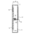
- 2 is a cross-sectional view taken along the line II of the wireless communication apparatus of FIG.
- the wireless communication device 1 includes a housing 11, a substrate 13, antennas 15 a to 15 d, a metal plate 17, an opening 18, and a detection unit 19. In addition, when it is not necessary to distinguish the antennas, they are described as “antenna 15”.
- the casing 11 has a rectangular parallelepiped shape in this example, but may have any shape as long as the antenna 15 and the metal plate 17 can be set to a predetermined distance d.
- the casing 11 is formed of a resin material in this example. But the material which forms the housing
- casing 11 is not limited to a resin material, unless it is a material which becomes a role of reflectors, such as a metal material.
- the casing 11 has an opening 18.
- the opening 18 is located near the center of the housing 11.
- the position of the opening 18 is not limited to the vicinity of the center of the housing 11 as long as the metal plate 17 is disposed at a position facing the antenna when the metal plate 17 is installed in the housing 11.
- the substrate 13 is installed inside the housing 11.
- the substrate 13 is installed on the side surface 11 a inside the housing 11, but a part of the substrate 13 may not be in contact with the side surface 11 a inside the housing 11.
- the substrate 13 is a single layer, but may be a multilayer. In the case of multiple layers, the position where the antenna 15 is installed can be the inner layer as described later.
- the antenna 15 is installed on the substrate 13.
- the number of elements of the antenna 15 is four.
- the number of elements is not limited to this, and may be one or more than four.
- the antenna 15 is a planar antenna in this example.
- the antenna 15 is formed by printing on the substrate 13.
- the antenna 15 is not limited to a printed planar antenna on the substrate 13, and a planar antenna such as a plate inverted F antenna (PIFA: Planar Inverted-F Antenna) or a patch antenna may be mounted on the substrate 13. Good.
- PIFA Planar Inverted-F Antenna
- the antenna 15 is configured on the front surface of the substrate 13 in this example, but may be configured on the back surface.
- the antenna 15 may be configured as an inner layer.
- a known split ring resonator (Split Ring Resonator, not shown) is disposed between the antenna elements.
- the distance between the antenna elements is shorter than when the split ring resonator is not disposed.
- the distance between the antenna elements is ⁇ / 2.
- the distance between the antenna elements is preferably ⁇ or more.
- the antenna 15 is a 5 GHz band wireless communication antenna.
- the distance between the antenna elements is preferably 60 mm or more.
- an antenna for wireless communication in the 2.45 GHz band may also be provided.
- the metal plate 17 has a function of reflecting radio waves.
- the metal plate 17 reflects the radio wave radiated from the antenna 15.
- the reflectance of the metal plate 17 is higher than the reflectance of the housing 11.
- the antenna 15a to the antenna 15d are inside the metal plate 17 in a plan view.
- the protrusion 17a is a part of the metal plate 17 in this example. That is, the protrusion 17a and the metal plate 17 are formed of the same material. When formed of the same material, the protrusion 17a and the metal plate 17 can be manufactured integrally. However, the protrusion 17a and the metal plate 17 may be made of different materials. In the case of another material, it is necessary to join the protrusion 17a and the metal plate 17 together. Further, the protrusion 17 a is inserted into the housing 11.
- the metal plate 17 When the metal plate 17 is installed in the housing 11, the metal plate 17 has a surface facing the substrate 13 and the antenna 15 installed on the substrate 13.
- the number of antenna elements installed on the substrate is four.
- the distance between each antenna and the metal plate 17 is preferably equal. If the distance between each antenna and the metal plate 17 is different, there is a difference in the degree of overlap between the radio wave radiated from each antenna and the radio wave reflected by the metal plate 17, which affects the directivity and the magnitude of the front gain. Because it gives. Therefore, in this example, the four antennas 15 and the metal plate 17 are configured to have the same distance. That is, the four antennas 15 and the metal plate 17 are parallel. In other words, the substrate 13 on which the antenna 15 is installed and the metal plate 17 are preferably parallel.
- the distance d between each antenna 15 and the metal plate 17 is preferably greater than ⁇ / 12 and less than 5 ⁇ / 12 with respect to the radio frequency used. More preferably, the distance d between each antenna 15 and the metal plate 17 is not less than ⁇ / 6 and not more than ⁇ / 3 with respect to the radio frequency used.
- the distance d between each antenna 15 and the metal plate 17 is more preferably ⁇ / 4 with respect to the radio frequency used.
- the radio frequency to be used is the 5 GHz band. Therefore, the distance d between each antenna 15 and the metal plate 17 is more preferably 15 mm.
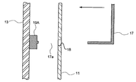
- FIG. 3 is an enlarged view (sectional view) of the periphery of the detection unit of the wireless communication device according to the embodiment of the present invention.
- the detection unit 19 is a photo interrupter.
- the photo interrupter has a light emitting portion 19a and a light receiving portion 19b that face each other.
- the detection unit 19 can detect that the metal plate 17 is installed in the housing 11 without contacting the protrusion 17a.
- the detection unit 19 is not limited to a photo interrupter, and may be another non-contact sensor.
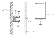
- FIG. 3A is an enlarged view (sectional view) of the periphery of the detection unit of the wireless communication device when a metal plate is not installed in the housing in the wireless communication device according to the embodiment of the present invention.
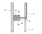
- FIG. 3B is an enlarged view (sectional view) of the periphery of the detection unit of the wireless communication device when a metal plate is installed in the housing in the wireless communication device according to the embodiment of the present invention.
- the metal plate 17 When the metal plate 17 is moved in the direction of the arrow in the drawing as shown in FIG. 3A and the light receiving portion 19b detects that the projection 17a blocks the light from the light emitting portion 19a as shown in FIG.
- the part 19A detects that a case including the metal plate 17 is installed in the housing 11.
- FIG. 4 is a block diagram for explaining a part of a wireless communication apparatus according to an embodiment of the present invention.
- the substrate 13 includes an antenna 15, a detection unit 19, an output unit 20, an RF unit 21, a baseband unit 23, and a control unit 25.
- the RF unit 21 processes a frequency band signal used in the wireless communication device 1.
- the RF unit 21 processes a signal of 5 GHz band.
- the RF unit 21 is connected to the antenna 15.
- the RF unit 21 is connected to the baseband unit 23.
- the reception mixer in the RF unit 21 converts the high frequency into an intermediate frequency (IF) and then converts it into a baseband signal.
- the RF unit 21 includes a known configuration such as various mixers for transmission and reception, an amplifier such as an LNA, and a filter such as a bandpass filter, but the description thereof is omitted here.
- the control unit 25 controls the operation mode based on the detection result output by the output unit.
- the control unit 25 performs various controls related to wireless LAN communication, such as retransmission control when an error occurs when a signal transmitted from the transmission side is decoded on the reception side, and transmission timing control. Further, the control unit 25 may perform control so as to reduce the transmission output of the antenna 15 when the detection unit 19 detects that the metal plate 17 is installed in the housing 11.
- the output unit 20 outputs the result detected by the detection unit 19. Then, the output result is used by the control unit 25.
- FIG. 5 is a diagram for explaining a simulation situation for confirming the directivity of the wireless communication apparatus according to the embodiment of the present invention.
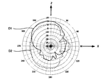
- 6A and 6B are simulation results showing the directivity of the wireless communication apparatus according to the embodiment of the present invention.
- the wireless communication device 1 ⁇ / b> A is installed in a housing 11, a substrate 13 installed in the housing, an antenna 15 a installed in the substrate, and a detachable installation in the housing.
- 1 includes a metal plate (reflecting plate) 17 that is parallel to the substrate 13, a detection unit (not shown) that detects the installation of the metal plate 17, and an output unit (not shown) that outputs the detection result of the detection unit. .
- the antenna 15a is a planar antenna for 5 GHz band.
- the housing 11 is a case made of a resin material.
- the resin case is designed so that the distance between the antenna 15a and the metal plate (reflecting plate) 17 is ⁇ / 4 (15 mm).
- the horizontal direction is the X-axis direction
- the vertical direction is the Y-axis direction
- the vertical direction from the substrate 13 to the opposite side of the metal plate 17 Is the Z-axis direction.
- D1 solid line
- D2 dashed line
- Antenna gain When the metal plate 17 is not attached to the housing 11, the antenna gain in the Z-axis direction is about 1 dBi.
- the antenna gain in the Z-axis direction is about 5 dBi.
- D3 solid line
- D4 broken line
- the antenna gain in the Z-axis direction is about 1 dBi.
- the antenna gain in the Z-axis direction is about 5 dBi. Then, when the metal plate 17 is attached to the housing 11, the antenna gain in the Z-axis direction is increased by 3 dB or more.
- the antenna 15a When the metal plate 17 is attached to the housing 11, the antenna 15a is a highly directional antenna. As you can see, it works. On the other hand, when the metal plate 17 is not attached to the housing 11, the antenna 15a does not have a large antenna gain in any direction, so that it can be seen that it operates as an antenna with low directivity. That is, the metal plate 17 can be said to be a switching unit that switches the antenna directivity from a relatively low state (first state) to a high state (second state). And a detection part detects the switching by this switching part.
- a plurality of antennas are provided on both a transmission side and a reception side, and a MIMO (Multiple Input Multiplex) that configures a multi-input multiple-output system via a wireless transmission path (channel).
- MIMO Multiple Input Multiplex
- the Output method is attracting attention.
- a plurality of antennas are provided with respect to the conventional technique in order to cope with the MIMO method, a problem arises that a plurality of waveguides and reflectors are required.
- a plurality of antennas 15 are formed on one substrate 13. That is, the plurality of antennas 15 are formed in the same plane. And the board
- the detection unit 19 automatically detects whether or not the metal plate 17 is installed in the housing 11. Therefore, the control unit 25 has an effect that the transmission output of the wireless communication device 1 can be automatically switched by the detection.
- the protrusion 17a is made of the same material as the metal plate 17, there is an effect that both can be manufactured integrally.
- the distance between the substrate 13 including the plurality of antennas 15 and the metal plate (reflecting plate) 17 can be determined by the protrusion 17a, and detection by the detection unit 19 is also performed. Therefore, the projection part 17a has an effect that one can play two roles.
- the detection part 19 can detect that the metal plate 17 was installed in the housing
- FIG. 7A is an enlarged view (cross-sectional view) of the periphery of the detection unit of the wireless communication device when a metal plate is not installed in the housing in the wireless communication device according to another embodiment of the present invention.
- FIG. 7B is an enlarged view (cross-sectional view) of the periphery of the detection unit of the wireless communication device when a metal plate is installed in the housing in the wireless communication device according to another embodiment of the present invention.
- This embodiment is substantially the same as the first embodiment, although the detection unit is different. Therefore, description of the same part is omitted, and different points will be described in detail.
- the detection unit 19A is a push switch in this example. Therefore, when the push switch is pushed by the protrusion 17a, it is detected that the metal plate 17 is installed in the housing 11. Accordingly, the detection unit 19A comes into contact with the protrusion 17a.
- the automatic detection of the metal plate 17 by the switch is not limited to the push switch, but may be a lever switch or the like.
- the detection unit 19 is not a non-contact sensor such as a photo interrupter but a push switch.
- the push switch is less expensive than the photo interrupter. Therefore, in this embodiment, there exists an effect that the detection part 19 can be comprised more cheaply.
- FIG. 8 is an explanatory diagram (perspective view) for illustrating a schematic configuration of a wireless communication apparatus according to another embodiment of the present invention.
- 9 is a cross-sectional view of the wireless communication apparatus of FIG. 8 taken along the line II-II.
- This embodiment is substantially the same as the first embodiment, except that the position of the detection unit and the opening are not provided. Therefore, description of the same part is omitted, and only different points will be described in detail.
- the detection unit 19B is a push switch installed on the upper surface of the housing 11. Of the case 16 covering the housing 11, the surface parallel to the substrate 13 is the metal plate 17B.
- the case 16 may be installed in the housing 11 so that the case 16 is difficult to move from the housing 11, and the upper surface of the housing 11 may be provided with irregularities so as to be engaged with the case 16.
- the detection unit 19B may not function. Therefore, the unevenness is provided as long as the detection unit 19B functions.
- FIG. 10A is an enlarged view (cross-sectional view) of the periphery of the detection unit of the wireless communication device when a metal plate is not installed in the housing in the wireless communication device according to another embodiment of the present invention.
- FIG. 10B is an enlarged view (cross-sectional view) of the periphery of the detection unit of the wireless communication device when a metal plate is installed in the housing in the wireless communication device according to another embodiment of the present invention.
- the detection unit 19B When the case 16 is moved in the direction of the arrow in the drawing as shown in FIG. 10A and the push switch (detection unit 19B) is pushed by the recess 16a of the case 16 as shown in FIG. 10B, the detection unit 19B is It is detected that a case including the metal plate 17 is installed on the body 11.
- This embodiment also has the same effect as the first embodiment.
- the housing 11 since the detection unit 19B is installed on the upper surface of the housing 11, the housing 11 does not have an opening portion like the opening 18 of the first embodiment. Therefore, when a general user installs the case 16 including the metal plate 17 in the housing 11, the detection unit 19 ⁇ / b> B can be installed while being visually confirmed.
- the control unit when a restriction is provided for the counterpart terminal that communicates with the wireless communication device 1, for example, when a threshold is provided for the reception sensitivity received from the counterpart terminal, the control unit is configured such that the detection unit 19 is provided on the casing 11 and the metal plate is provided on the casing 11.
- the threshold value of the reception sensitivity of the counterpart terminal for communication is changed. For example, when a metal plate (reflecting plate) 17 is not installed in the casing 11 of the wireless communication device 1 and communication is performed with a counterpart terminal receiving at a reception sensitivity of ⁇ 80 dB or more, as shown in FIG.
- the counterpart terminals 30a and 30b communicate with the wireless communication apparatus 1, but the counterpart terminal 30c outside the residence indicated by the broken line does not communicate with the radio communication apparatus 1.
- the control unit determines the counterpart terminals 30a and 30b receiving with a reception sensitivity of ⁇ 80 dBm or more. Communication is performed, but when a metal plate (reflecting plate) 17 is installed in the casing 11, the threshold value is controlled so that communication is performed only with the counterpart terminals 30a and 30b receiving at a reception sensitivity of ⁇ 77 dBm or higher. May be.
- RSSI Received Signal Strength Indication, Received Signal Strength Indicator, or received signal strength.
- RSSI is a circuit or signal for measuring the strength of a signal received by a wireless communication device.
- the threshold of the counterpart terminal with which the wireless communication apparatus communicates can be changed.
- This embodiment is substantially the same as the first embodiment.
- the function of the control unit is different from that of the first embodiment. Therefore, description of the same part is omitted, and different points will be described in detail.
- the control unit may define the modulation method and the wireless LAN standard when the detection unit 19 detects that the metal plate 17 is installed in the housing 11.
- the transmission / reception environment of the wireless communication device is better when the metal plate 17 is installed in the housing 11.
- the detection unit 19 detects that the metal plate 17 is installed in the housing 11
- the modulation method may be changed to 256QAM.
- the detection unit 19 detects that the metal plate 17 is installed in the housing 11, it does not perform IEEE 802.11ac communication but performs other communication such as IEEE 802.11g. It may be.
- the transmission / reception environment of the wireless communication device is better when the metal plate 17 is installed in the housing 11. Therefore, when the detection unit 19 detects that the metal plate 17 is installed in the housing 11, the output unit 20 outputs the detection result, and the control unit 25 installs the metal plate 17 in the housing 11. It is controlled to transmit a signal indicating that it has been detected. Then, the signal is transmitted from the antenna 15 to the counterpart terminal.
- the counterpart terminal receiving the signal can reduce power consumption by suppressing the amplification factor of the intermediate frequency amplifier.
- the wireless communication apparatus transmits a signal indicating whether or not the metal plate 17 is installed in the housing 11 to the counterpart terminal, There is an effect that the counterpart terminal can adaptively reduce the power consumption.
- a plurality of the antennas of the present invention may be installed on the substrate.
- a part of the metal plate may be inserted into the housing.
- the distance between the substrate and the facing surface may be greater than ⁇ / 12 and less than 5 ⁇ / 12.
- the detection unit may detect the installation of the metal plate without contacting a part of the inserted metal plate.
- a control unit for controlling the operation mode may be further included based on the detection result output by the output unit.
- the control unit may reduce the output of the antenna.
- the antenna may transmit the result detected by the detection unit to the receiver side.
Landscapes
- Engineering & Computer Science (AREA)
- Computer Networks & Wireless Communication (AREA)
- Signal Processing (AREA)
- Physics & Mathematics (AREA)
- Electromagnetism (AREA)
- Transceivers (AREA)
- Variable-Direction Aerials And Aerial Arrays (AREA)
- Aerials With Secondary Devices (AREA)
Abstract
一般ユーザにとって、指向性を容易に変更することが可能な無線通信装置を提供する。本発明の一実施形態によれば、筐体と、前記筐体の内部に設置された基板と、前記基板に設置されたアンテナと、前記筐体に着脱可能に設置され、設置時において前記基板に対向する面を有する金属板と、前記金属板の設置を検知する検知部と、前記検知部の検知結果を出力する出力部と、を含む無線通信装置が提供される。前記アンテナは、前記基板に複数個設置されてもよい。
Description
本発明は、無線通信装置に関する。
従来、無線LAN用の無線通信装置として、指向性アンテナを有する無線通信装置と無指向性アンテナを有する無線通信装置とを一つの装置で実現する技術として、所定長の導波器と反射器と放射器とを、相互の位置関係を変更可能に構成し、導波器、反射器および放射器が、所定間隔を置いて平行かつ中心を同じくした指向性アンテナとして機能する第1の配置と、導波器、反射器および放射のうちの少なくともいずれか一つの配置を変更して、無指向性アンテナとして機能する第2の配置とに切換可能な構造を備えたアンテナ装置が提案されている(特許文献1)。
このようなアンテナ装置は、導波器、反射器および放射器の相互の位置関係が変更可能であり、指向性アンテナとして機能する第1の配置と、無指向性アンテナとして機能する第2の配置との変更ができるので、一つのアンテナ装置でありながら、指向性アンテナとしても無指向性アンテナとしても用いることができる。
しかしながら、特許文献1に開示された技術では、放射器の位置を動かすことによって無数の放射パターンを実現することが可能ではあるものの、一般ユーザにとっては、どの位置が最適な配置かわからず、導波器、反射器および放射器の相互の位置関係によっては、かえって利得の劣化が生じるという問題がある。
本発明は、上記のような従来技術に伴う課題を解決しようとするものであって、その目的とするところは、一般ユーザにとって、指向性を容易に変更することが可能な無線通信装置を提供するところにある。
本発明の一実施形態によると、筐体と、前記筐体の内部に設置された基板と、前記基板に設置されたアンテナと、前記筐体に着脱可能に設置され、前記筐体の反射率よりも高い反射率を有し、設置時において前記基板に対向する面を有する金属板と、前記金属板の設置を検知する検知部と、前記検知部の検知結果を出力する出力部と、を含む無線通信装置が提供される。
本発明の一実施形態によると、筐体と、前記筐体の内部に設置された基板と、前記基板に設置されたアンテナと、前記アンテナの指向性を第1状態から第2状態に切り替える切替部と、前記切替部による切り替えを検知する検知部と、前記検知部の検知結果を出力する出力部と、を含む無線通信装置が提供される。
本発明によれば、一般ユーザにとって、指向性を容易に変更することが可能な無線通信装置を提供することができる。
以下、本発明の一実施形態について、図面を参照しながら詳細に説明する。以下に示す実施形態は本発明の実施形態の一例であって、本発明はこれらの実施形態に限定されるものではない。なお、本実施形態で参照する図面において、同一部分または同様な機能を有する部分には同一の符号または類似の符号(数字の後にA、Bなどを付しただけの符号)を付し、その繰り返しの説明は省略する場合がある。また、図面の寸法比率は説明の都合上実際の比率とは異なったり、構成の一部が図面から省略されたりする場合がある。
<第1実施形態>
図1及び図2を用いて、本発明の一実施形態に係る無線通信装置について説明する。図1は、本発明の一実施形態に係る無線通信装置の概略構成を示すための説明図(斜視図)である。図2は、図1の無線通信装置のI―I断面図である。無線通信装置1は、筐体11、基板13、アンテナ15a乃至15d、金属板17、開口部18及び検知部19を含む。なお、アンテナの区別が不要な場合には、「アンテナ15」と表記する。
図1及び図2を用いて、本発明の一実施形態に係る無線通信装置について説明する。図1は、本発明の一実施形態に係る無線通信装置の概略構成を示すための説明図(斜視図)である。図2は、図1の無線通信装置のI―I断面図である。無線通信装置1は、筐体11、基板13、アンテナ15a乃至15d、金属板17、開口部18及び検知部19を含む。なお、アンテナの区別が不要な場合には、「アンテナ15」と表記する。
筐体11は、この例では、直方体形状となっているが、アンテナ15と金属板17とが所定の距離dとすることが可能であれば、どのような形状であってもよい。筐体11は、この例では、樹脂材料で形成されている。もっとも、筐体11を形成する材料は、金属材料等の反射板の役割となる材料でなければ、樹脂材料に限定されない。
また、この例では、筐体11は、開口部18を有する。図2のように断面でみると、開口部18は、筐体11の中央付近に位置する。もっとも、金属板17を筐体11に設置したときに、アンテナと対向する位置に金属板17が配置されるのであれば、開口部18の位置は、筐体11の中央付近に限定されない。
基板13は、筐体11の内部に設置されている。この例では、基板13は、筐体11の内部の側面11aに設置されているが、基板13の一部が、筐体11の内部の側面11aに接していなくてもよい。また、この例では、基板13は、単層であるが、多層であってもよい。多層である場合には、後記のとおり、アンテナ15の設置する位置を内層にすることもできる。
アンテナ15は、基板13に設置されている。この例では、アンテナ15の素子数は、4つであるが、これに限定されるものではなく、単数であってもよいし、4つ以外の複数であってもよい。
また、アンテナ15は、この例では、平面アンテナである。そして、アンテナ15は、この例では、基板13上にプリントすることによって形成されている。アンテナ15は、基板13上のプリントによる平面アンテナに限定されるものではなく、板状逆Fアンテナ(PIFA:Planar Inverted-F Antenna)やパッチアンテナ等の平面アンテナを基板13上に搭載してもよい。
アンテナ15は、この例では、基板13の表面に構成されているが、裏面に構成されてもよい。基板13が多層基板である場合には、アンテナ15は、内層に構成されてもよい。
この例では、アンテナ素子同士の干渉を避けるために、アンテナ素子間に公知のスプリットリングレゾネータ(Split Ring Resonator、図示せず)が配置されている。アンテナ素子間にスプリットリングレゾネータを配置する場合には、これを配置しない場合と比較して、アンテナ素子間の距離が短くなる。この例では、アンテナ素子間の距離は、λ/2である。もっとも、スプリットリングレゾネータを配置しなくてもよい。スプリットリングレゾネータを配置しない場合には、アンテナ素子間の距離は、λ以上であることが好ましい。この例では、アンテナ15は、5GHz帯の無線通信用のアンテナである。そのため、アンテナ素子間の距離は、60mm以上であることが好ましい。もっとも、2.45GHz帯の無線通信用のアンテナもあってもよい。
金属板17は、電波を反射する機能を有する。金属板17は、この例では、アンテナ15から放射された電波を反射する。金属板17の反射率は、筐体11の反射率よりも高い。金属板17が、平面視においてアンテナ15aからアンテナ15dの内側にあると、アンテナ15aからアンテナ15dまでが、平面視において金属板17の内側にある場合と比較して、前方利得の増加量が減る。そのため、アンテナ15aからアンテナ15dまでが、平面視において金属板17の内側にある方が好ましい。
突起部17aは、この例では、金属板17の一部である。すなわち、突起部17aと金属板17とは同じ材料で形成されている。同じ材料で形成される場合には、突起部17aと金属板17とは一体に製造することが可能である。もっとも、突起部17aと金属板17とは、別の材料であってもよい。別の材料である場合には、突起部17aと金属板17とを接合する必要がある。また、突起部17aは、筐体11の内部に挿入される。
金属板17が筐体11に設置された場合、金属板17は、基板13、基板13に設置されたアンテナ15と対向する面を有する。この例では、基板に設置されたアンテナ素子数は、4つである。アンテナ素子数が複数の場合、各アンテナと金属板17との距離は等しいことが好ましい。各アンテナと金属板17との距離が異なると、各アンテナで放射された電波と金属板17で反射された電波との重なりの程度に差が生じ、指向性や前方利得の大きさに影響を与えるからである。そのため、この例では、4つのアンテナ15と金属板17とは、距離が等しくなるように構成される。すなわち、4つのアンテナ15と金属板17とは、平行になる。言い換えると、アンテナ15が設置された基板13と金属板17とは平行であることが好ましい。
金属板17を筐体11に設置し、金属板17が筐体11から動きにくいようにするために、筐体11の一部に凹凸の箇所を設け、金属板17を当該箇所と噛み合うような形状としてもよい。
金属板17が反射板としての効果を発揮するためには、各アンテナ15から放射された電波と、金属板17から反射された電波の位相が概ねそろう必要がある。そこで、各アンテナ15と金属板17との距離dは、好ましくは、使用する無線周波数に対し、λ/12より大きく5λ/12未満である。より好ましくは、各アンテナ15と金属板17との距離dは、使用する無線周波数に対し、λ/6以上λ/3以下である。各アンテナ15と金属板17との距離dをλ/4にすると、アンテナ15から放射される電波と金属板17で反射された電波との位相が一致し、前方利得が増加する。そのため、各アンテナ15と金属板17との距離dは、より好ましくは、使用する無線周波数に対し、λ/4である。この例では、使用する無線周波数は、5GHz帯である。したがって、各アンテナ15と金属板17との距離dは、より好ましくは、15mmである。
検知部19は、金属板17の設置を検知する。図3は、本発明の一実施形態に係る無線通信装置の検知部の周辺を拡大した図(断面図)である。検知部19は、この例では、フォトインタラプタである。フォトインタラプタは、対向する発光部19aと受光部19bを有するところ、発光部19aからの光を突起部17aが遮るのを受光部19bで検出することによって、金属板17が筐体11に設置されたことを検知する。そのため、検知部19は、突起部17aに接触することなく、金属板17が筐体11に設置されたことを検知することができる。もっとも、検知部19は、フォトインタラプタに限定されるものではなく、他の非接触のセンサであってもよい。
図3Aは、本発明の一実施形態に係る無線通信装置において筐体に金属板が設置されていない場合の無線通信装置の検知部の周辺を拡大した図(断面図)である。図3Bは、本発明の一実施形態に係る無線通信装置において筐体に金属板が設置されている場合の無線通信装置の検知部の周辺を拡大した図(断面図)である。
図3Aに示すように、金属板17を図面の矢印の方向に移動させて、図3Bに示すように、発光部19aからの光を突起部17aが遮るのを受光部19bで検出すると、検知部19Aは、筐体11に金属板17を含むケースが設置されたことを検知する。
図4は、本発明の一実施形態に係る無線通信装置の一部を説明するためのブロック図である。基板13は、アンテナ15、検知部19、出力部20、RF部21、ベースバンド部23、制御部25を備える。
RF部21は、無線通信装置1で利用される周波数帯の信号を処理する。RF部21は、この例では、5GHz帯の信号を処理する。RF部21は、アンテナ15に接続されている。また、RF部21は、ベースバンド部23に接続されている。この例では、周波数帯が5GHzと高周波数であるため、RF部21にある受信ミキサが当該高周波数を中間周波数(Intermediate Frequency;IF)に変換した上で、ベースバンド信号に変換する。なお、RF部21は、送受信用の各種ミキサ、LNA等のアンプ、バンドパスフィルタなどのフィルタなど公知の構成を備えるが、ここでの説明は省略する。
制御部25は、出力部が出力する検知結果に基づいて、動作モードを制御する。制御部25は、例えば、送信側から送られた信号が受信側で復号した際に誤りが生じた場合の再送制御や、送信タイミングの制御など無線LAN通信に関する各種の制御を行う。また、制御部25は、検知部19が、筐体11に金属板17が設置されたことを検知したときに、アンテナ15の送信出力を低減するように制御してもよい。
出力部20は、検知部19が検知した結果を出力する。そして、その出力された結果は、制御部25によって用いられる。
<シミュレーション>
図5、図6A及び6Bを用いて、本発明の一実施形態に係る無線通信装置について、金属板17の有無による指向性の変化について説明する。図5は、本発明の一実施形態に係る無線通信装置の指向性を確認するためのシミュレーション状況を説明するための図である。図6A及び図6Bは、本発明の一実施形態に係る無線通信装置の指向性を示すシミュレーション結果である。
図5、図6A及び6Bを用いて、本発明の一実施形態に係る無線通信装置について、金属板17の有無による指向性の変化について説明する。図5は、本発明の一実施形態に係る無線通信装置の指向性を確認するためのシミュレーション状況を説明するための図である。図6A及び図6Bは、本発明の一実施形態に係る無線通信装置の指向性を示すシミュレーション結果である。
図5に示すように、無線通信装置1Aは、筐体11と、筐体の内部に設置された基板13と、基板に設置されたアンテナ15aと、筐体に着脱可能に設置され、設置時において基板13に平行となる金属板(反射板)17と、金属板17の設置を検知する検知部(図示せず)と、検知部の検知結果を出力する出力部(図示せず)を備える。
アンテナ15aは、基板13の左端からx1=10mm、y1=5mmの位置に配置した。アンテナ15aは、5GHz帯用の平面アンテナである。また、筐体11は、樹脂材料で形成されるケースである。アンテナ15aと金属板(反射板)17との距離が、λ/4(15mm)となるように樹脂ケースが設計されている。
図6に示すように、基板13と同じ面で、横方向をX軸方向、縦方向をY軸方向、基板13から金属板17とは反対側の垂直方向(無線通信装置1Aの正面方向)をZ軸方向とする。図6Aに示すように、D1(実線)は、筐体11に金属板17を取り付けた場合のアンテナ利得であり、D2(破線)は、筐体11に金属板17場合を取り付けていない場合のアンテナ利得である。筐体11に金属板17を取り付けていない場合、Z軸方向のアンテナ利得は、1dBi程度である。他方、筐体11に金属板17を取り付けた場合、Z軸方向のアンテナ利得は、5dBi程度である。同様に、図6Bに示すように、D3(実線)は、筐体11に金属板17を取り付けた場合のアンテナ利得であり、D4(破線)は、筐体11に金属板17を取り付けていない場合のアンテナ利得である。筐体11に金属板17を取り付けていない場合、Z軸方向のアンテナ利得は、1dBi程度である。他方、筐体11に金属板17を取り付けた場合、Z軸方向のアンテナ利得は、5dBi程度である。そうすると、筐体11に金属板17を取り付けたことにより、Z軸方向のアンテナ利得が3dB以上大きくなり、筐体11に金属板17を取り付けた場合には、アンテナ15aは、指向性の高いアンテナとして動作していることがわかる。一方、筐体11に金属板17を取り付けていない場合には、アンテナ15aは、どの方向にも大きなアンテナ利得ではないことから、指向性の低いアンテナとして動作していることがわかる。すなわち、金属板17は、アンテナの指向性を相対的に低い状態(第1状態)から高い状態(第2状態)に切り替える切替部といえる。そして、検知部は、この切替部による切り替えを検知する。
本実施形態では、金属板17を筐体11に設置するという容易な方法で、指向性の低いアンテナを有する無線通信装置を指向性の強いアンテナを有する無線通信装置に切り替えることができるという効果を奏する。
ところで、近年、無線通信を介した情報伝送方式において、送信側及び受信側の双方に複数のアンテナを設け、無線伝送路(チャネル)を介した多入力多出力系を構成するMIMO(Multiple Input Multiple Output)方式が注目を集めている。MIMO方式等に対応するために、従来技術に対して複数のアンテナを設ける場合、複数の導波器、反射器が必要となるといった問題が生じる。
他方、本実施形態では、複数のアンテナ15が、一つの基板13に形成されている。すなわち、複数のアンテナ15は、同一平面状に形成される。そして、複数のアンテナ15を備える基板13と金属板(反射板)17とは、対向する。複数のアンテナ15を備える基板13と金属板(反射板)17とが平行である場合には、反射板は1つで足りる。したがって、MIMO方式等に対応するために複数のアンテナを設けても、反射器を複数要しない無線通信装置を提供することができるという効果を奏する。
本実施形態では、検知部19は、金属板17が筐体11に設置されたかどうかを自動で検知する。そのため、制御部25は、当該検知によって、無線通信装置1の送信出力を自動で切り替えることができるという効果を奏する。
突起部17aが金属板17と同じ材料である場合には、両者を一体に製造することができるという効果を奏する。また、突起部17aによって、複数のアンテナ15を備える基板13と金属板(反射板)17との距離を決めることができるとともに、検知部19による検知も行われる。したがって、突起部17aは、1つで2つの役割を果たすことができるという効果を奏する。
さらに、本実施形態では、検知部19は、フォトインタラプタなど突起部17aと接触することなく、金属板17が筐体11に設置されたことを検知することができる。そのため、検知部19も突起部17aも機械的に壊れにくいという効果を奏する。
<第2実施形態>
図7A及び7Bを用いて、本発明の第2実施形態について説明する。図7Aは、本発明の他の実施形態に係る無線通信装置において筐体に金属板が設置されていない場合の無線通信装置の検知部の周辺を拡大した図(断面図)である。図7Bは、本発明の他の実施形態に係る無線通信装置において筐体に金属板が設置されている場合の無線通信装置の検知部の周辺を拡大した図(断面図)である。本実施形態は、検知部が異なるが、第1実施形態と概ね同じである。そこで、同じ箇所についての説明は省略し、異なる点について詳細に説明する。
図7A及び7Bを用いて、本発明の第2実施形態について説明する。図7Aは、本発明の他の実施形態に係る無線通信装置において筐体に金属板が設置されていない場合の無線通信装置の検知部の周辺を拡大した図(断面図)である。図7Bは、本発明の他の実施形態に係る無線通信装置において筐体に金属板が設置されている場合の無線通信装置の検知部の周辺を拡大した図(断面図)である。本実施形態は、検知部が異なるが、第1実施形態と概ね同じである。そこで、同じ箇所についての説明は省略し、異なる点について詳細に説明する。
検知部19Aは、この例では、プッシュスイッチである。そのため、突起部17aでプッシュスイッチが押されると、金属板17が筐体11に設置されたことが検知される。したがって、検知部19Aは、突起部17aに接触することになる。スイッチによる金属板17の自動検出は、プッシュスイッチに限定されるものではなく、レバースイッチなどであってもよい。
図7Aに示すように、金属板17を図面の矢印の方向に移動させて、図7Bに示すように、金属板17の突起部17aでプッシュスイッチ(検知部19A)を押すと、検知部19Aは、筐体11に金属板17を含むケースが設置されたことを検知する。
本実施形態でも、検知部19、突起部17aが機械的に壊れにくいという効果を除いて、第1実施形態と同様の効果を奏する。
また、本実施形態では、検知部19は、フォトインタラプタなど非接触センサではなく、プッシュスイッチなどである。一般に、プッシュスイッチ方がフォトインタラプタよりも安価である。したがって、本実施形態では、より安価に検知部19を構成することができるという効果を奏する。
<第3実施形態>
図8及び図9を用いて、本発明の他の実施形態に係る無線通信装置について説明する。図8は、本発明の他の実施形態に係る無線通信装置の概略構成を示すための説明図(斜視図)である。図9は、図8の無線通信装置のII-II断面図である。本実施形態は、第1実施形態と概ね同じであるが、検知部の位置や開口部がない点が異なる。そこで、同じ箇所についての説明は省略し、異なる点についてのみ詳細に説明する。
図8及び図9を用いて、本発明の他の実施形態に係る無線通信装置について説明する。図8は、本発明の他の実施形態に係る無線通信装置の概略構成を示すための説明図(斜視図)である。図9は、図8の無線通信装置のII-II断面図である。本実施形態は、第1実施形態と概ね同じであるが、検知部の位置や開口部がない点が異なる。そこで、同じ箇所についての説明は省略し、異なる点についてのみ詳細に説明する。
検知部19Bは、この例では、筐体11の上面に設置されているプッシュスイッチである。筐体11を覆っているケース16のうち、基板13と平行な面が金属板17Bである。
ケース16を筐体11に設置して、ケース16が筐体11から動きにくいようにするために、筐体11の上面に凹凸を設け、ケース16と噛み合うようにしてもよい。もっとも、この凹凸の高さが高すぎると、検知部19Bが機能しなくなるおそれがあることから、検知部19Bが機能する限りで、凹凸は設けられる。
図10Aは、本発明の他の実施形態に係る無線通信装置において筐体に金属板が設置されていない場合の無線通信装置の検知部の周辺を拡大した図(断面図)である。図10Bは、本発明の他の実施形態に係る無線通信装置において筐体に金属板が設置されている場合の無線通信装置の検知部の周辺を拡大した図(断面図)である。
図10Aに示すように、ケース16を図面の矢印の方向に移動させて、図10Bに示すように、ケース16の凹部16aでプッシュスイッチ(検知部19B)を押すと、検知部19Bは、筐体11に金属板17を含むケースが設置されたことを検知する。
本実施形態でも、第1実施形態と同様の効果を奏する。
また、本実施形態では、検知部19Bが筐体11の上面に設置されるため、筐体11に、第1実施形態の開口部18のような開口部分がない。そのため、一般ユーザが、金属板17を含むケース16を筐体11に設置する際に、検知部19Bを目視で確認しながら設置することができるという効果を奏する。
<第4実施形態>
本実施形態は、第1実施形態と概ね同じである。本実施形態では、制御部の機能が、第1実施形態と異なる。そこで、同じ箇所についての説明は省略し、異なる点について詳細に説明する。
本実施形態は、第1実施形態と概ね同じである。本実施形態では、制御部の機能が、第1実施形態と異なる。そこで、同じ箇所についての説明は省略し、異なる点について詳細に説明する。
本実施形態では、無線通信装置1と通信する相手方端末について制限を設ける場合、例えば、相手方端末から受信する受信感度に閾値を設ける場合、制御部は、検知部19が、筐体11に金属板17が設置されたことを検知したときに、通信する相手方端末の受信感度の閾値を変更する。例えば、無線通信装置1の筐体11に金属板(反射板)17が設置されておらず、受信感度が-80dB以上で受信している相手方端末と通信を行う場合、図11に示すように、相手方端末30a及び30bは、無線通信装置1と通信をしているが、破線で示す住居の外にある相手方端末30cは、無線通信装置1と通信をしていない。このときに、制御部は、無線通信装置1の筐体11に金属板(反射板)17が設置されていない場合は、受信感度が-80dBm以上で受信している相手方端末30a及び30bとは通信を行うが、筐体11に金属板(反射板)17が設置された場合には、受信感度が-77dBm以上で受信している相手方端末30a及び30bとしか通信しないように、閾値を制御してもよい。筐体11に金属板(反射板)17が設置されている場合には、金属板17によって無線通信装置の受信レベルが改善されうるからである。なお、受信感度は、RSSI(Received Signal Strength Indication、Received Signal Strength Indicatorまたは、受信信号強度)で測定する。RSSIとは、無線通信機器が受信する信号の強度を測定するための回路または信号のことである。
本実施形態では、筐体11に金属板17が設置されることによって、無線通信装置が通信を行う相手方端末の閾値を変更することができるという効果を奏する。その結果、不必要に距離の離れた相手方端末までカバーすることなく、通信を行う相手方端末の範囲の適正化を維持することができるという効果を奏する。
<第5実施形態>
本実施形態は、第1実施形態と概ね同じである。本実施形態では、制御部の機能が、第1実施形態と異なる。そこで、同じ箇所についての説明は省略し、異なる点について詳細に説明する。
本実施形態は、第1実施形態と概ね同じである。本実施形態では、制御部の機能が、第1実施形態と異なる。そこで、同じ箇所についての説明は省略し、異なる点について詳細に説明する。
本実施形態では、制御部は、検知部19が、筐体11に金属板17が設置されたことを検知したときに、変調方式や無線LANの規格を規定してもよい。ここで、筐体11に金属板17が設置されている方が、無線通信装置の送受信環境が良い。例えば、筐体11に金属板17が設置されていないときに、64QAMの変調方式を用いている場合に、検知部19が筐体11に金属板17が設置されていることを検知したとき、変調方式を256QAMに変えてもよい。同様に、例えば、検知部19が筐体11に金属板17が設置されていることを検知したときは、IEEE 802.11acの通信は行わずに、IEEE 802.11gなど他の通信を行うようにしてもよい。
本実施形態では、金属板17の筐体11に対する設置の有無によって、変調方式を変更することができるといった効果を奏する。
<第6実施形態>
本実施形態は、第1実施形態と概ね同じである。本実施形態では、制御部の機能が、第1実施形態と異なる。そこで、同じ箇所についての説明は省略し、異なる点について詳細に説明する。
本実施形態は、第1実施形態と概ね同じである。本実施形態では、制御部の機能が、第1実施形態と異なる。そこで、同じ箇所についての説明は省略し、異なる点について詳細に説明する。
筐体11に金属板17が設置されている方が、無線通信装置の送受信環境は良い。そこで、検知部19が、筐体11に金属板17が設置されたことを検知したときに、出力部20が、検知結果を出力し、制御部25が、筐体11に金属板17が設置されたことを検知したことを表わす信号を送信するように制御する。そして、アンテナ15から当該信号が相手方端末に送信される。当該信号を受信した相手方端末は、中間周波増幅器の増幅率を抑えるなどして低消費電力化を図ることができる。
本実施形態では、筐体11に金属板17が設置されているかどうか応じて、無線通信装置が相手方端末に筐体11に金属板17が設置されているかどうかを表わす信号を送信することによって、相手方端末が適応的に低消費電力化を図ることができるという効果を奏する。
なお、本発明は上記の実施形態に限られたものではなく、趣旨を逸脱しない範囲で適宜変更することが可能である。
本発明の前記アンテナは、前記基板に複数個設置されてもよい。
前記金属板の一部が前記筐体内部に挿入されてもよい。
前記基板と前記対向する面との距離は、λ/12より大きく5λ/12未満であってもよい。
前記検知部は、前記挿入される前記金属板の一部に接触せずに、前記金属板の設置を検知してもよい。
前記出力部が出力する検知結果に基づいて、動作モードを制御する制御部をさらに含んでもよい。
前記制御部は、前記アンテナの出力を低下させてもよい。
前記アンテナは、前記検知部が検知した結果を受信機側に送信してもよい。
1、1A:無線通信装置 11:筐体 13:基板
15:アンテナ 17:金属板 17a:突起部 18:開口部
19、19A:検知部
D1、D3:筐体に金属板を取り付けた場合のアンテナ利得
D2、D4:筐体に金属板を取り付けていない場合のアンテナ利得
810:アンテナ装置 811:第1の基板 812:第2の基板
815:インナーケース 816:アウタケース 818:ネジ
821:放射器 822:導波器 823:反射器
15:アンテナ 17:金属板 17a:突起部 18:開口部
19、19A:検知部
D1、D3:筐体に金属板を取り付けた場合のアンテナ利得
D2、D4:筐体に金属板を取り付けていない場合のアンテナ利得
810:アンテナ装置 811:第1の基板 812:第2の基板
815:インナーケース 816:アウタケース 818:ネジ
821:放射器 822:導波器 823:反射器
Claims (9)
- 筐体と、
前記筐体の内部に設置された基板と、
前記基板に設置されたアンテナと、
前記筐体に着脱可能に設置され、前記筐体の反射率よりも高い反射率を有し、設置時において前記基板に対向する面を有する金属板と、
前記金属板の設置を検知する検知部と、
前記検知部の検知結果を出力する出力部と、
を含む無線通信装置。 - 前記アンテナは、前記基板に複数個設置されることを特徴とする請求項1に記載の無線通信装置。
- 前記金属板の一部が前記筐体内部に挿入されることを特徴とする請求項1に記載の無線通信装置。
- 前記基板と前記対向する面との距離は、λ/12より大きく5λ/12未満であることを特徴とする請求項1に記載の無線通信装置。
- 前記検知部は、前記挿入される前記金属板の一部に接触せずに、前記金属板の設置を検知することを特徴とする請求項1に記載の無線通信装置。
- 前記出力部が出力する検知結果に基づいて、動作モードを制御する制御部をさらに含むことを特徴とする請求項1に記載の無線通信装置。
- 前記制御部は、前記アンテナの出力を低下させることを特徴とする請求項6に記載の無線通信装置。
- 前記アンテナは、前記検知部が検知した結果を受信機側に送信することを特徴とする請求項1に記載の無線通信装置。
- 筐体と、
前記筐体の内部に設置された基板と、
前記基板に設置されたアンテナと、
前記アンテナの指向性を第1状態から第2状態に切り替える切替部と、
前記切替部による切り替えを検知する検知部と、
前記検知部の検知結果を出力する出力部と、
を含む無線通信装置。
Priority Applications (3)
| Application Number | Priority Date | Filing Date | Title |
|---|---|---|---|
| CN201680073990.9A CN108432044B (zh) | 2015-12-18 | 2016-12-12 | 无线通信设备 |
| US16/006,026 US10892563B2 (en) | 2015-12-18 | 2018-06-12 | Wireless communication device |
| US17/101,344 US11309640B2 (en) | 2015-12-18 | 2020-11-23 | Wireless communication device |
Applications Claiming Priority (2)
| Application Number | Priority Date | Filing Date | Title |
|---|---|---|---|
| JP2015247893A JP6249014B2 (ja) | 2015-12-18 | 2015-12-18 | 無線通信装置 |
| JP2015-247893 | 2015-12-18 |
Related Child Applications (1)
| Application Number | Title | Priority Date | Filing Date |
|---|---|---|---|
| US16/006,026 Continuation US10892563B2 (en) | 2015-12-18 | 2018-06-12 | Wireless communication device |
Publications (1)
| Publication Number | Publication Date |
|---|---|
| WO2017104598A1 true WO2017104598A1 (ja) | 2017-06-22 |
Family
ID=59056557
Family Applications (1)
| Application Number | Title | Priority Date | Filing Date |
|---|---|---|---|
| PCT/JP2016/086860 Ceased WO2017104598A1 (ja) | 2015-12-18 | 2016-12-12 | 無線通信装置 |
Country Status (4)
| Country | Link |
|---|---|
| US (2) | US10892563B2 (ja) |
| JP (1) | JP6249014B2 (ja) |
| CN (1) | CN108432044B (ja) |
| WO (1) | WO2017104598A1 (ja) |
Families Citing this family (4)
| Publication number | Priority date | Publication date | Assignee | Title |
|---|---|---|---|---|
| CN110809837B (zh) * | 2017-06-16 | 2022-04-29 | 雅马哈株式会社 | 无线通信装置 |
| JP6560722B2 (ja) * | 2017-08-29 | 2019-08-14 | 京セラ株式会社 | 受電アンテナ、受電装置、アンテナ部品、及び受電アンテナの組立方法 |
| CN110931938B (zh) * | 2018-09-20 | 2021-04-16 | 宏碁股份有限公司 | 电子装置 |
| CN114095050B (zh) * | 2020-07-29 | 2022-12-27 | 华为技术有限公司 | 一种无线终端 |
Citations (4)
| Publication number | Priority date | Publication date | Assignee | Title |
|---|---|---|---|---|
| JPH0243803A (ja) * | 1988-08-04 | 1990-02-14 | Nippon Telegr & Teleph Corp <Ntt> | パラボラアンテナ |
| JP2000284854A (ja) * | 1999-03-31 | 2000-10-13 | Toshiba Corp | 携帯型電子機器 |
| JP2011015295A (ja) * | 2009-07-03 | 2011-01-20 | Mitsubishi Electric Corp | 無線通信装置 |
| JP2011061861A (ja) * | 2010-12-06 | 2011-03-24 | Toshiba Corp | 電子機器 |
Family Cites Families (6)
| Publication number | Priority date | Publication date | Assignee | Title |
|---|---|---|---|---|
| US6211830B1 (en) * | 1998-06-10 | 2001-04-03 | Matsushita Electric Industrial Co., Ltd. | Radio antenna device |
| TWI280690B (en) * | 2003-03-18 | 2007-05-01 | Tdk Corp | Electronic device for wireless communications and reflector device for wireless communication cards |
| JP3783006B2 (ja) | 2003-07-01 | 2006-06-07 | 株式会社バッファロー | アンテナ装置 |
| KR20090130812A (ko) * | 2008-06-16 | 2009-12-24 | 주식회사 케이엠더블유 | 형상 변경이 가능한 기지국 안테나 |
| JP4649522B2 (ja) * | 2009-05-29 | 2011-03-09 | 株式会社東芝 | ノートブック型パーソナルコンピュータ |
| CN103682635B (zh) * | 2012-09-25 | 2016-01-13 | 西门子公司 | 一种射频识别天线、射频识别天线的控制单元及控制方法和射频识别系统 |
-
2015
- 2015-12-18 JP JP2015247893A patent/JP6249014B2/ja active Active
-
2016
- 2016-12-12 WO PCT/JP2016/086860 patent/WO2017104598A1/ja not_active Ceased
- 2016-12-12 CN CN201680073990.9A patent/CN108432044B/zh active Active
-
2018
- 2018-06-12 US US16/006,026 patent/US10892563B2/en active Active
-
2020
- 2020-11-23 US US17/101,344 patent/US11309640B2/en active Active
Patent Citations (4)
| Publication number | Priority date | Publication date | Assignee | Title |
|---|---|---|---|---|
| JPH0243803A (ja) * | 1988-08-04 | 1990-02-14 | Nippon Telegr & Teleph Corp <Ntt> | パラボラアンテナ |
| JP2000284854A (ja) * | 1999-03-31 | 2000-10-13 | Toshiba Corp | 携帯型電子機器 |
| JP2011015295A (ja) * | 2009-07-03 | 2011-01-20 | Mitsubishi Electric Corp | 無線通信装置 |
| JP2011061861A (ja) * | 2010-12-06 | 2011-03-24 | Toshiba Corp | 電子機器 |
Also Published As
| Publication number | Publication date |
|---|---|
| US20210075126A1 (en) | 2021-03-11 |
| JP2017112578A (ja) | 2017-06-22 |
| US11309640B2 (en) | 2022-04-19 |
| US10892563B2 (en) | 2021-01-12 |
| CN108432044B (zh) | 2021-05-07 |
| JP6249014B2 (ja) | 2017-12-20 |
| US20180294579A1 (en) | 2018-10-11 |
| CN108432044A (zh) | 2018-08-21 |
Similar Documents
| Publication | Publication Date | Title |
|---|---|---|
| US11309640B2 (en) | Wireless communication device | |
| CN113328762B (zh) | 具有天线阵列增减能力的无线网络 | |
| KR101382085B1 (ko) | 휴대용 장치 | |
| US10651670B1 (en) | Electronic devices with wireless charging antenna arrays | |
| CA2837561C (en) | Antenna structure having a shorting leg | |
| US20110148736A1 (en) | Multi-input multi-output antenna for improving isolation | |
| US20120013519A1 (en) | Multiple-input multiple-output (mimo) multi-band antennas with a conductive neutralization line for signal decoupling | |
| WO2018179870A1 (en) | Antenna, configuration method of antenna and wireless communication device | |
| US10164343B2 (en) | Communication device | |
| KR102279153B1 (ko) | 샤크 핀 안테나 | |
| EP2893593B1 (en) | Multiband monopole antenna apparatus with ground plane aperture | |
| US20220399918A1 (en) | Apparatus that supports spatial diversity, at least at reception | |
| US10270176B2 (en) | Communication device | |
| US9837724B2 (en) | Antenna system | |
| KR20180046694A (ko) | 안테나 장치 및 그를 포함하는 전자 장치 | |
| KR20180047392A (ko) | 안테나장치 | |
| US9761931B2 (en) | Wireless network device | |
| JP6841328B2 (ja) | 無線通信装置 | |
| CN112467355B (zh) | 天线系统 | |
| JP4422657B2 (ja) | アンテナ装置 | |
| JP4469320B2 (ja) | アンテナ装置 | |
| US12621040B2 (en) | Gain pattern overlap reduction | |
| JP2013197636A (ja) | 無線通信式携帯型tvチューナ | |
| KR20250017066A (ko) | 빔포밍 신호를 전송하기 위한 전자 장치 및 방법 | |
| KR101956044B1 (ko) | 무선 통신 장치 및 이의 제어 방법 |
Legal Events
| Date | Code | Title | Description |
|---|---|---|---|
| 121 | Ep: the epo has been informed by wipo that ep was designated in this application |
Ref document number: 16875575 Country of ref document: EP Kind code of ref document: A1 |
|
| NENP | Non-entry into the national phase |
Ref country code: DE |
|
| 122 | Ep: pct application non-entry in european phase |
Ref document number: 16875575 Country of ref document: EP Kind code of ref document: A1 |