WO2017104105A1 - 音声音響信号符号化装置、音声音響信号復号装置、音声音響信号符号化方法、及び、音声音響信号復号方法 - Google Patents
音声音響信号符号化装置、音声音響信号復号装置、音声音響信号符号化方法、及び、音声音響信号復号方法 Download PDFInfo
- Publication number
- WO2017104105A1 WO2017104105A1 PCT/JP2016/004891 JP2016004891W WO2017104105A1 WO 2017104105 A1 WO2017104105 A1 WO 2017104105A1 JP 2016004891 W JP2016004891 W JP 2016004891W WO 2017104105 A1 WO2017104105 A1 WO 2017104105A1
- Authority
- WO
- WIPO (PCT)
- Prior art keywords
- signal
- encoding
- encoded data
- channel
- audio
- Prior art date
- Legal status (The legal status is an assumption and is not a legal conclusion. Google has not performed a legal analysis and makes no representation as to the accuracy of the status listed.)
- Ceased
Links
Images

Classifications
-
- G—PHYSICS
- G10—MUSICAL INSTRUMENTS; ACOUSTICS
- G10L—SPEECH ANALYSIS TECHNIQUES OR SPEECH SYNTHESIS; SPEECH RECOGNITION; SPEECH OR VOICE PROCESSING TECHNIQUES; SPEECH OR AUDIO CODING OR DECODING
- G10L19/00—Speech or audio signals analysis-synthesis techniques for redundancy reduction, e.g. in vocoders; Coding or decoding of speech or audio signals, using source filter models or psychoacoustic analysis
- G10L19/008—Multichannel audio signal coding or decoding using interchannel correlation to reduce redundancy, e.g. joint-stereo, intensity-coding or matrixing
-
- G—PHYSICS
- G10—MUSICAL INSTRUMENTS; ACOUSTICS
- G10L—SPEECH ANALYSIS TECHNIQUES OR SPEECH SYNTHESIS; SPEECH RECOGNITION; SPEECH OR VOICE PROCESSING TECHNIQUES; SPEECH OR AUDIO CODING OR DECODING
- G10L19/00—Speech or audio signals analysis-synthesis techniques for redundancy reduction, e.g. in vocoders; Coding or decoding of speech or audio signals, using source filter models or psychoacoustic analysis
-
- H—ELECTRICITY
- H04—ELECTRIC COMMUNICATION TECHNIQUE
- H04R—LOUDSPEAKERS, MICROPHONES, GRAMOPHONE PICK-UPS OR LIKE ACOUSTIC ELECTROMECHANICAL TRANSDUCERS; DEAF-AID SETS; PUBLIC ADDRESS SYSTEMS
- H04R1/00—Details of transducers, loudspeakers or microphones
- H04R1/20—Arrangements for obtaining desired frequency or directional characteristics
- H04R1/32—Arrangements for obtaining desired frequency or directional characteristics for obtaining desired directional characteristic only
- H04R1/40—Arrangements for obtaining desired frequency or directional characteristics for obtaining desired directional characteristic only by combining a number of identical transducers
- H04R1/406—Arrangements for obtaining desired frequency or directional characteristics for obtaining desired directional characteristic only by combining a number of identical transducers microphones
-
- H—ELECTRICITY
- H04—ELECTRIC COMMUNICATION TECHNIQUE
- H04S—STEREOPHONIC SYSTEMS
- H04S3/00—Systems employing more than two channels, e.g. quadraphonic
- H04S3/008—Systems employing more than two channels, e.g. quadraphonic in which the audio signals are in digital form, i.e. employing more than two discrete digital channels
-
- H—ELECTRICITY
- H04—ELECTRIC COMMUNICATION TECHNIQUE
- H04S—STEREOPHONIC SYSTEMS
- H04S2400/00—Details of stereophonic systems covered by H04S but not provided for in its groups
- H04S2400/15—Aspects of sound capture and related signal processing for recording or reproduction
Definitions
- the present disclosure relates to a speech acoustic signal encoding device, a speech acoustic signal decoding device, a speech acoustic signal encoding method, and a speech acoustic signal decoding method.
- Non-Patent Document 1 discloses an EVS (Enhanced Voice Services) codec algorithm.
- EVS codec an input signal is analyzed, and the input signal is encoded using an optimal encoding mode according to the characteristics of the input signal. Encoding and decoding processes (referred to as “signals”) can be performed efficiently.
- Non-Patent Document 2 discloses a beamformer (for example, Griffiths-Jim type beamformer) technique using a microphone array.
- a beamformer for example, Griffiths-Jim type beamformer
- Non-Patent Document 2 discloses a configuration for extracting an acoustic signal coming from a specific direction using a sum signal of each channel signal of a microphone array and a differential signal of adjacent channel signals Is disclosed.
- One aspect of the present disclosure is an audio / acoustic signal encoding apparatus, an audio / acoustic signal decoding apparatus, an audio / acoustic signal encoding method, and the like that can suppress degradation of beamforming performance when encoding multi-channel signals in an EVS codec. And it is providing the audio acoustic signal decoding method.
- An audio-acoustic signal encoding apparatus generates a sum signal by adding all of a plurality of channel signals constituting a multi-channel audio-acoustic input signal, and a difference signal between channels of the plurality of channel signals
- a conversion unit that generates the first encoded data by encoding the addition signal in a coding mode according to the characteristics of the addition signal, and an encoding used for encoding the addition signal
- a second encoding unit that encodes the differential signals in the mode to generate second encoded data; and a multiplexing unit that multiplexes the first encoded data and the second encoded data.
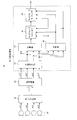
- the figure which shows the structural example of a multichannel acoustic signal encoding-decoding system The figure which shows an example of the internal structure of a converter Diagram showing an example of the internal configuration of the encoder. The figure which shows an example of the internal structure of a decoder The figure which shows an example of the internal structure of an inverter The figure which shows the structural example of a sound collection processing system
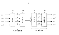
- FIG. 1 shows a configuration example of a system according to the present embodiment.
- the system 1 shown in FIG. 1 includes at least an encoding device 10 (multi-channel encoder) that encodes an audio-acoustic signal and a decoding device 20 (multi-channel decoder) that decodes the audio-acoustic signal.
- encoding device 10 multi-channel encoder
- decoding device 20 multi-channel decoder
- Each channel signal of the multi-channel digital acoustic signal is input to the encoding device 10.
- a multi-channel digital acoustic signal is obtained by performing digital conversion on an analog acoustic signal acquired by a microphone array unit (not shown).
- FIG. 1 shows a case where four channel signals (ch1 to ch4) are input, the number of channels of the multichannel digital acoustic signal is not limited to four.
- the encoding device 10 employs a configuration including a converter 11 (corresponding to a conversion unit) and an encoder 12.
- the converter 11 performs weighted addition processing on each channel signal (ch1 to ch4) that is an input signal, and converts each channel signal (ch1 to ch4) into a multichannel digital signal (S, X, Y, Z). To do.
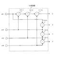
- FIG. 2 shows an example of the internal configuration of the converter 11.
- the subtractors 112-1, 112-2 and 112-3 shown in FIG. 2 generate differential signals between channels of the plurality of channel signals ch1 to ch4.
- the subtractor 112-2 is the adjacent channel signal ch2 and the channel.
- the converter 11 outputs a multi-channel digital signal including the addition signal S and the difference signals X, Y, and Z to the encoder 12.
- the encoder 12 encodes the multichannel digital signal output from the converter 11 using the EVS codec, generates monaural encoded data, multiplexes the monaural encoded data, and outputs the data as multichannel encoded data. .
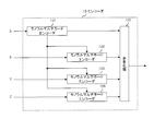
- FIG. 3 shows an example of the internal configuration of the encoder 12.
- the encoder 12 illustrated in FIG. 3 employs a configuration including monaural multimode encoders 121, 122, 123, and 124 and a multiplexing unit 125.
- the monaural multimode encoder 121 (corresponding to the first encoding unit) encodes the addition signal S input from the converter 11 to generate monaural encoded data (corresponding to the first encoded data).
- the monaural multimode encoder 121 outputs the monaural encoded data to the multiplexing unit 125.
- the monaural multimode encoder 121 determines the encoding mode according to the characteristics (for example, the type of speech, non-speech, etc.) of the added signal S that is input during encoding, and uses the determined encoding mode. Then, the addition signal S is encoded. The monaural multimode encoder 121 outputs mode information indicating the encoding mode used for encoding the addition signal S to the monaural multimode encoders 122 to 124. The monaural multimode encoder 121 encodes mode information, includes the monaural encoded data, and outputs the encoded data to the multiplexing unit 125.
- the characteristics for example, the type of speech, non-speech, etc.
- the monaural multimode encoders 121 to 124 share the encoding mode used for encoding the addition signal S.
- the monaural multi-mode encoders 122 to 124 (corresponding to the second encoding unit) use the encoding mode indicated by the mode information input from the monaural multi-mode encoder 121 and use the difference signal X input from the converter 11. , Y, and Z are encoded to generate monaural encoded data (corresponding to the second encoded data).
- the monaural multimode encoders 122 to 124 output the monaural encoded data to the multiplexing unit 125.
- the multiplexing unit 125 multiplexes the encoded data input from the multimode encoders 121 to 124 and outputs the multiplexed data as multichannel encoded data to the transmission path.
- the decoding device 20 employs a configuration including a decoder 21 and an inverse converter 22 (corresponding to an inverse conversion unit).
- the decoder 21 separates the received multi-channel encoded data into a plurality of monaural encoded data, decodes the plurality of monaural encoded data, and outputs a decoded multi-channel digital signal (S ′, X ′, Y ′, Z ') Get.
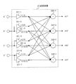
- FIG. 4 shows an example of the internal configuration of the decoder 21.
- the decoder 21 shown in FIG. 4 employs a configuration including a demultiplexer 211 and monaural multimode decoders 212 to 215.
- the demultiplexer 211 separates the multi-channel encoded data received from the encoding device 10 through the transmission path into monaural encoded data corresponding to the addition signal and monaural encoded data corresponding to each difference signal. .
- the demultiplexer 211 outputs the monaural encoded data corresponding to the addition signal to the monaural multimode decoder 212 (corresponding to the first decoding unit), and outputs the monaural encoded data corresponding to each difference signal to the monaural multimode decoder 213 to 215 (corresponding to the second decoding unit).
- the monaural encoded data corresponding to the addition signal includes mode information indicating the encoding mode used for encoding the addition signal.
- the monaural multimode decoder 212 decodes the mode information input from the demultiplexer 211 and identifies the encoding mode used in the encoding device 10.
- the monaural multimode decoder 212 decodes the monaural encoded data corresponding to the addition signal S based on the specified encoding mode, and outputs the obtained decoded signal S ′ to the inverse converter 22.
- the monaural multimode decoder 212 outputs mode information indicating the coding mode to the monaural multimode decoders 213 to 215.
- the monaural multimode decoders 212 to 215 share the encoding mode used for encoding the addition signal S in the encoding device 10.
- the monaural multimode decoders 213 to 215 respectively correspond to the monaural signals corresponding to the differential signals X, Y, and Z input from the demultiplexer 211 according to the encoding mode indicated by the mode information input from the monaural multimode decoder 212.
- the encoded data is decoded, and the obtained decoded signals X ′, Y ′, and Z ′ are output to the inverse converter 22.
- the inverse converter 22 performs weighted addition on the decoded signals S ′, X ′, Y ′, and Z ′ input from the decoder 21, and decodes the decoded signals S ′, X ′, Y ′, and Z ′ into the decoded multi signal.
- Channel digital sound signals (ch1 ′ to ch4 ′) are converted.
- FIG. 5 shows an example of the internal configuration of the inverse converter 22.
- weighting coefficients for the decoded signals S ′, X ′, Y ′, and Z ′ are set in the amplifiers 221-1 to 221-7.
- the adders 222-1 to 222-4 add the signals output from the amplifiers 221-1 to 221-7 to generate each decoded channel signal of the multichannel digital acoustic signal.
- the amplifiers 221-1 to 221-7 and the adders 222-1 to 222-4 generate the decoded channel signals ch1 'to ch4' using the following equations.
- encoding apparatus 10 mixes and encodes a multi-channel signal into an addition signal for all channels and a difference signal between channels. At this time, the encoding device 10 also uses the encoding mode determined in the encoding of the addition signal for encoding the difference signal. In addition, the decoding device 20 decodes monaural encoded data corresponding to each of the addition signal and the difference signal according to the encoding mode used in the encoding device 10.
- the decoding apparatus 20 can reduce phase distortion between decoded channel signals.
- the encoding mode used for encoding / decoding is the same for all channels, and the signals of all channels are expressed using the decoded signal of the average signal of all channels. For this reason, in the decoding apparatus 20, a multi-channel signal in which distortion characteristics of a decoded signal are different between channels caused by using different encoding modes at the same time or not sharing an encoding error in each channel. Quality degradation can be avoided.
- the decoding device 20 it is possible to reduce the influence of the coding error on the beam forming process using the phase relationship of each channel signal. That is, according to the present embodiment, it is possible to suppress degradation of beam forming performance when performing beam forming processing using a multi-channel signal encoded by an EVS codec.
- the encoding device 10 since the encoding mode is shared by each monaural multimode encoder of the encoding device 10 and each monaural multimode decoder of the decoding device 20, the encoding device 10 has mode information for all the monaural multimode encoders 121 to 124. Need not be encoded, and only one mode information need be transmitted to the decoding device 20.
- the encoding device 10 determines the encoding mode based on the addition signal S for all channels, it is possible to select an optimal encoding mode for the entire multi-channel. This is because the sum signal S includes average characteristics of the sound in the multi-channel acoustic signal, whereas the difference signals X, Y, and Z have a signal level smaller than that of the sum signal S. This is because it is difficult to capture the characteristics of
- the effect of reducing the coding distortion of the differential signal can be obtained.
- this Embodiment demonstrated the encoding apparatus which has several encoding modes (multi-mode), it is applicable also to the encoding apparatus which has only one encoding mode and does not perform mode switching. is there.
- the converter a plurality of channel signals constituting at least three channels of multi-channel audio-acoustic input signals are all added to generate a one-channel addition signal, and at least a difference signal between the channels of the plurality of channel signals is generated. Two channels are generated.
- the first encoding unit encodes the one-channel addition signal output from the converter to generate first encoded data
- the second encoding unit encodes at least two-channel difference signals.
- the multiplexing unit multiplexes the first encoded data and the second encoded data to generate and output multi-channel encoded data.
- the encoding error added to each channel signal can be shared by re-synthesizing each channel signal using the decoded addition signal in the encoder, as in the multimode of the present embodiment. Therefore, it is possible to reduce the influence of the coding error on the beam forming process using the phase relationship of each channel signal.
- the decoding apparatus that performs demultiplexing according to the encoding mode indicated by the encoding mode information output from the encoding apparatus has been described, but the encoding mode information is not input. It is also applicable to cases.
- FIG. 6 shows a configuration example of the sound collection system according to the present embodiment.
- the sound collection system 1a shown in FIG. 6 employs a configuration including the microphone array unit 30, the sound collection processing unit 40, and the encoding device 10 and the decoding device 20 described in the first embodiment.
- the microphone array unit 30 includes a plurality of microphones (four microphones in FIG. 6) that convert acoustic signals into analog electrical signals, and an A / D converter that converts analog electrical signals into digital acoustic signals.
- the microphone array unit 30 outputs a multi-channel digital acoustic signal composed of digital acoustic signals (channel signals ch1 to ch4) corresponding to each microphone to the encoding device 10.
- the encoding device 10 encodes the multi-channel digital acoustic signal
- the decoding device 20 decodes the multi-channel encoded data received from the encoding device 10, and each decoded channel signal (ch1 ′) ⁇ ch4 ′) is output to the sound collection processing unit 40.
- the sound collection processing unit 40 performs a beam forming process on the decoded multi-channel acoustic signal input from the decoding device 20, and extracts and outputs only a signal to be collected (target signal).
- the sound collection processing unit 40 has a configuration including a phase correction unit 41, an addition unit 42, a subtraction unit 43, a side lobe canceller 44, and a side lobe suppressor 45.
- the phase correction unit 41 corrects the phase of each decoded channel signal of the decoded multi-channel acoustic signal according to the arrival direction of the target signal, and outputs the decoded channel signal after the phase correction to the adding unit 42 and the subtracting unit 43. .
- the adding unit 42 adds all the decoded channel signals after phase correction. In the addition signal, the component of the target signal is emphasized.
- the adder 42 outputs the addition signal to the side lobe canceller 44.
- the subtracting unit 43 generates a differential signal between adjacent channels with respect to the decoded channel signal after phase correction. In the difference signal between adjacent channels, the component of the target signal is canceled and the noise component is emphasized.
- the subtractor 43 outputs the difference signal to the side lobe canceller 44 and the side lobe suppressor 45.
- the side lobe suppressor 44 and the side lobe suppressor 45 use the addition signal input from the addition unit 42 and the difference signal input from the subtraction unit 43 to enhance the component of the target signal and suppress components other than the target signal. Functions as a suppressor.
- the side lobe canceller 44 removes a component corresponding to the difference signal input from the subtraction unit 43 from the addition signal input from the addition unit 42 to thereby obtain a signal component other than the target signal (such as a noise component). ) To emphasize the target signal.
- the side lobe suppressor 45 uses the signal input from the side lobe canceller 44 and the difference signal input from the subtractor 43 to further suppress signal components other than the target signal in the frequency domain (spectral domain), Emphasize the target signal.
- the output signal of the side lobe suppressor 45 is output as the final output signal of the beam form processing.
- the processing of the sound collection processing unit 40 may be performed by a cloud server. That is, the decoding device 20 may transmit the decoded multichannel acoustic signal to a cloud server connected via a network such as the Internet, and the cloud server may perform sound collection processing.
- FIG. 5 demonstrated the case where the weighting coefficient was set in the inverse converter 22 of the decoding apparatus 20, the weighting coefficient of the converter 11 and the inverse converter 22 can be changed arbitrarily.
- a weighting coefficient may be set in the converter 11 of the encoding device 10.
- the converter 11 generates the addition signal S and the difference signals X, Y, and Z using Equation 2.
- the inverse converter 22 generates the decoded channel signals ch1 ′ to ch4 ′ using Equation 3.
- the contents of the weighted addition of the converter 11 and the inverse converter 22 are the contents of the addition process of the addition unit 42 and the subtraction process of the subtraction unit 43 in the sound collection process. If they are different, they may be adjusted accordingly.
- X, Y, and Z can be channel-to-channel differential signals as shown in Equation 4.
- Each decoding channel signal ch1 'to ch4' corresponding to this can be derived.
- each functional block used in the description of each of the above embodiments is typically realized as an LSI which is an integrated circuit.
- the integrated circuit may control each functional block used in the description of the above embodiment, and may include an input terminal and an output terminal. These may be individually made into one chip, or may be made into one chip so as to include a part or all of them.
- the name used here is LSI, but it may also be called IC, system LSI, super LSI, or ultra LSI depending on the degree of integration.
- the method of circuit integration is not limited to LSI, and may be realized by a dedicated circuit or a general-purpose processor.
- An FPGA Field Programmable Gate Array
- a reconfigurable processor that can reconfigure the connection or setting of circuit cells inside the LSI may be used.
- the audio / acoustic signal encoding apparatus generates a sum signal by adding all of a plurality of channel signals constituting a multi-channel audio / acoustic input signal, and generates a difference signal between the channels of the plurality of channel signals.
- a first encoding unit that encodes the addition signal in an encoding mode according to the characteristics of the addition signal to generate first encoded data, and a differential signal in the encoding mode used for encoding the addition signal
- a second encoding unit that generates the second encoded data by respectively encoding the first encoded data and the second encoded data, and a multiplexing unit that generates the multi-channel encoded data,
- the structure which comprises is taken.
- the audio / acoustic signal encoding apparatus adds a plurality of channel signals constituting at least three channels of multi-channel audio / acoustic input signals to generate a one-channel addition signal, and the channels of the plurality of channel signals
- a second encoding unit that generates second encoded data, and a multiplexing unit that multiplexes the first encoded data and the second encoded data to generate multi-channel encoded data,
- the structure to comprise is taken.
- the audio / acoustic input signal is a signal output from the microphone array unit.
- the differential signal is a differential signal between adjacent channels of a plurality of channel signals.
- the first encoded data includes mode information indicating the encoding mode used for encoding the addition signal.
- the speech / acoustic signal decoding apparatus first separates the multi-channel encoded data output from the speech / acoustic signal encoding apparatus into first encoded data and second encoded data.
- the speech acoustic signal decoding apparatus includes a demultiplexing unit, a first decoding unit, a second decoding unit, and an inverse conversion unit.
- the first encoded data is obtained by adding an addition signal generated by adding all of the plurality of channel signals constituting the multi-channel audio / acoustic input signal in the audio / acoustic signal encoding apparatus.
- the second encoded data is encoded in the encoding mode used for encoding the difference signal between the channels of the plurality of channel signals in the audio-acoustic signal encoding apparatus.
- the first decoding unit decodes the first encoded data in the encoding mode used for encoding the addition signal to obtain a decoded addition signal.
- the second decoding unit decodes the second encoded data in the encoding mode used for encoding the addition signal to obtain a decoded differential signal.
- the inverse transform unit performs weighted addition on the decoded addition signal and the decoded differential signal to generate a decoded speech acoustic signal.
- the differential signal is a differential signal between adjacent channels of a plurality of channel signals.
- the first encoded data includes mode information indicating the encoding mode used for encoding the addition signal.
- the sound collection system of the present disclosure includes a sound collection processing unit that performs a beam forming process on the decoded speech acoustic signal output from the decoding device and extracts a target signal.
- the sound collection processing unit is phase-corrected with a phase correcting unit that corrects the phase of each decoded channel signal of the decoded speech acoustic signal, an adding unit that adds all the phase-corrected decoded channel signals to generate an added signal, and A subtracting unit that generates a difference signal between adjacent channels of the decoded channel signal, and a suppression unit that enhances a component of the target signal and suppresses components other than the target signal using the addition signal and the difference signal.
- the audio / acoustic signal encoding method of the present disclosure generates a sum signal by adding all of a plurality of channel signals constituting a multi-channel audio / acoustic input signal, and generates a difference signal between channels of the plurality of channel signals.
- the encoded signal is encoded in the encoding mode according to the characteristics of the added signal to generate first encoded data, and the differential signal is encoded in the encoding mode used for encoding the added signal, respectively.
- Data is generated, and the first encoded data and the second encoded data are multiplexed to generate multi-channel encoded data.
- the speech / acoustic signal decoding method of the present disclosure separates multi-channel encoded data output from the speech / acoustic signal encoding apparatus into first encoded data and second encoded data.
- the first encoded data is obtained by encoding an addition signal generated by adding all of a plurality of channel signals constituting a multi-channel audio / acoustic input signal according to the characteristics of the addition signal in the audio / acoustic signal encoding apparatus. It is generated by encoding in mode.
- the second encoded data is generated by encoding the difference signals between the channels of the plurality of channel signals in the encoding mode used for encoding the added signal in the audio / acoustic signal encoding apparatus.
- the first encoded data is decoded in the encoding mode used for encoding the addition signal to obtain a decoded addition signal.
- the second encoded data is decoded in the encoding mode used for encoding the addition signal to obtain a decoded differential signal. Weighted addition is performed on the decoded addition signal and the decoded differential signal to generate a decoded speech acoustic signal.
- One aspect of the present disclosure is useful for an apparatus that performs encoding and decoding of multi-channel audio-acoustic (sound) signals.
Landscapes
- Engineering & Computer Science (AREA)
- Physics & Mathematics (AREA)
- Health & Medical Sciences (AREA)
- Signal Processing (AREA)
- Acoustics & Sound (AREA)
- Multimedia (AREA)
- Audiology, Speech & Language Pathology (AREA)
- Human Computer Interaction (AREA)
- Computational Linguistics (AREA)
- Otolaryngology (AREA)
- Mathematical Physics (AREA)
- Stereophonic System (AREA)
- Compression, Expansion, Code Conversion, And Decoders (AREA)
- Circuit For Audible Band Transducer (AREA)
Priority Applications (3)
| Application Number | Priority Date | Filing Date | Title |
|---|---|---|---|
| EP16875095.8A EP3392881B1 (en) | 2015-12-15 | 2016-11-16 | Audio acoustics signal encoding apparatus, audio acoustics signal decoding apparatus, audio acoustics signal encoding method, and audio acoustics signal decoding method |
| CN201680059429.5A CN108140394B (zh) | 2015-12-15 | 2016-11-16 | 语音音频信号编码装置及其方法、解码装置及其方法 |
| US15/976,987 US10424308B2 (en) | 2015-12-15 | 2018-05-11 | Audio sound signal encoding device, audio sound signal decoding device, audio sound signal encoding method, and audio sound signal decoding method |
Applications Claiming Priority (2)
| Application Number | Priority Date | Filing Date | Title |
|---|---|---|---|
| JP2015-244243 | 2015-12-15 | ||
| JP2015244243A JP6721977B2 (ja) | 2015-12-15 | 2015-12-15 | 音声音響信号符号化装置、音声音響信号復号装置、音声音響信号符号化方法、及び、音声音響信号復号方法 |
Related Child Applications (1)
| Application Number | Title | Priority Date | Filing Date |
|---|---|---|---|
| US15/976,987 Continuation US10424308B2 (en) | 2015-12-15 | 2018-05-11 | Audio sound signal encoding device, audio sound signal decoding device, audio sound signal encoding method, and audio sound signal decoding method |
Publications (1)
| Publication Number | Publication Date |
|---|---|
| WO2017104105A1 true WO2017104105A1 (ja) | 2017-06-22 |
Family
ID=59056323
Family Applications (1)
| Application Number | Title | Priority Date | Filing Date |
|---|---|---|---|
| PCT/JP2016/004891 Ceased WO2017104105A1 (ja) | 2015-12-15 | 2016-11-16 | 音声音響信号符号化装置、音声音響信号復号装置、音声音響信号符号化方法、及び、音声音響信号復号方法 |
Country Status (5)
| Country | Link |
|---|---|
| US (1) | US10424308B2 (enExample) |
| EP (1) | EP3392881B1 (enExample) |
| JP (1) | JP6721977B2 (enExample) |
| CN (1) | CN108140394B (enExample) |
| WO (1) | WO2017104105A1 (enExample) |
Families Citing this family (5)
| Publication number | Priority date | Publication date | Assignee | Title |
|---|---|---|---|---|
| CN107731238B (zh) * | 2016-08-10 | 2021-07-16 | 华为技术有限公司 | 多声道信号的编码方法和编码器 |
| CN106710600B (zh) * | 2016-12-16 | 2020-02-04 | 广州广晟数码技术有限公司 | 多声道音频信号的去相关编码方法和装置 |
| MY206514A (en) | 2018-07-04 | 2024-12-19 | Fraunhofer Ges Zur Frderung Der Angewandten Forschung E V | Multisignal audio coding using signal whitening as preprocessing |
| JP7176418B2 (ja) * | 2019-01-17 | 2022-11-22 | 日本電信電話株式会社 | 多地点制御方法、装置及びプログラム |
| CN113259083B (zh) * | 2021-07-13 | 2021-09-28 | 成都德芯数字科技股份有限公司 | 一种调频同步网相位同步方法 |
Citations (2)
| Publication number | Priority date | Publication date | Assignee | Title |
|---|---|---|---|---|
| JP2013545128A (ja) * | 2010-10-13 | 2013-12-19 | サムスン エレクトロニクス カンパニー リミテッド | 多チャネルオーディオ信号をダウンミックスする方法及び装置 |
| JP2015011076A (ja) * | 2013-06-26 | 2015-01-19 | 日本放送協会 | 音響信号符号化装置、音響信号符号化方法、および音響信号復号化装置 |
Family Cites Families (8)
| Publication number | Priority date | Publication date | Assignee | Title |
|---|---|---|---|---|
| JP3175446B2 (ja) * | 1993-11-29 | 2001-06-11 | ソニー株式会社 | 情報圧縮方法及び装置、圧縮情報伸張方法及び装置、圧縮情報記録/伝送装置、圧縮情報再生装置、圧縮情報受信装置、並びに記録媒体 |
| US5619524A (en) * | 1994-10-04 | 1997-04-08 | Motorola, Inc. | Method and apparatus for coherent communication reception in a spread-spectrum communication system |
| CN1243621A (zh) * | 1997-09-12 | 2000-02-02 | 皇家菲利浦电子有限公司 | 具有改进的丢失部分重构功能的传输系统 |
| JP4163294B2 (ja) * | 1998-07-31 | 2008-10-08 | 株式会社東芝 | 雑音抑圧処理装置および雑音抑圧処理方法 |
| HUP0301368A3 (en) * | 2003-05-20 | 2005-09-28 | Amt Advanced Multimedia Techno | Method and equipment for compressing motion picture data |
| ATE521143T1 (de) * | 2005-02-23 | 2011-09-15 | Ericsson Telefon Ab L M | Adaptive bitzuweisung für die mehrkanal- audiokodierung |
| WO2009116280A1 (ja) * | 2008-03-19 | 2009-09-24 | パナソニック株式会社 | ステレオ信号符号化装置、ステレオ信号復号装置およびこれらの方法 |
| EP2209328B1 (en) * | 2009-01-20 | 2013-10-23 | Lg Electronics Inc. | An apparatus for processing an audio signal and method thereof |
-
2015
- 2015-12-15 JP JP2015244243A patent/JP6721977B2/ja active Active
-
2016
- 2016-11-16 CN CN201680059429.5A patent/CN108140394B/zh active Active
- 2016-11-16 WO PCT/JP2016/004891 patent/WO2017104105A1/ja not_active Ceased
- 2016-11-16 EP EP16875095.8A patent/EP3392881B1/en active Active
-
2018
- 2018-05-11 US US15/976,987 patent/US10424308B2/en active Active
Patent Citations (2)
| Publication number | Priority date | Publication date | Assignee | Title |
|---|---|---|---|---|
| JP2013545128A (ja) * | 2010-10-13 | 2013-12-19 | サムスン エレクトロニクス カンパニー リミテッド | 多チャネルオーディオ信号をダウンミックスする方法及び装置 |
| JP2015011076A (ja) * | 2013-06-26 | 2015-01-19 | 日本放送協会 | 音響信号符号化装置、音響信号符号化方法、および音響信号復号化装置 |
Also Published As
| Publication number | Publication date |
|---|---|
| EP3392881A4 (en) | 2018-10-24 |
| CN108140394A (zh) | 2018-06-08 |
| CN108140394B (zh) | 2022-03-25 |
| JP2017111230A (ja) | 2017-06-22 |
| EP3392881A1 (en) | 2018-10-24 |
| US20180261233A1 (en) | 2018-09-13 |
| EP3392881B1 (en) | 2020-05-06 |
| JP6721977B2 (ja) | 2020-07-15 |
| US10424308B2 (en) | 2019-09-24 |
Similar Documents
| Publication | Publication Date | Title |
|---|---|---|
| US8332229B2 (en) | Low complexity MPEG encoding for surround sound recordings | |
| RU2640647C2 (ru) | Устройство и способ преобразования первого и второго входных каналов, по меньшей мере, в один выходной канал | |
| RU2650026C2 (ru) | Устройство и способ для многоканального прямого-окружающего разложения для обработки звукового сигнала | |
| CN108140394B (zh) | 语音音频信号编码装置及其方法、解码装置及其方法 | |
| KR102600284B1 (ko) | 고차 앰비소닉스(hoa) 신호를 압축하는 방법, 압축된 hoa 신호를 압축 해제하는 방법, hoa 신호를 압축하기 위한 장치, 및 압축된 hoa 신호를 압축 해제하기 위한 장치 | |
| EP3120352B1 (en) | Method for compressing a higher order ambisonics (hoa) signal, method for decompressing a compressed hoa signal, apparatus for compressing a hoa signal, and apparatus for decompressing a compressed hoa signal | |
| JP7764402B2 (ja) | 空間オーディオ表現およびレンダリング | |
| JP2011124872A (ja) | 音源分離装置、方法及びプログラム | |
| KR20230165855A (ko) | 공간 오디오 객체 분리 | |
| CA3212985A1 (en) | Combining spatial audio streams | |
| WO2015140293A1 (en) | Method for compressing a higher order ambisonics (hoa) signal, method for decompressing a compressed hoa signal, apparatus for compressing a hoa signal, and apparatus for decompressing a compressed hoa signal | |
| CN106471580B (zh) | 针对hoa数据帧表示的压缩确定表示非差分增益值所需的最小整数比特数的方法和设备 | |
| JP2015528925A (ja) | オーディオ信号処理装置および方法 | |
| CN116762127A (zh) | 量化空间音频参数 | |
| JP2017111230A5 (enExample) | ||
| GB2574667A (en) | Spatial audio capture, transmission and reproduction | |
| CN113646836A (zh) | 声场相关渲染 | |
| JP5340378B2 (ja) | チャネル信号生成装置、音響信号符号化装置、音響信号復号装置、音響信号符号化方法及び音響信号復号方法 | |
| CN112133316B (zh) | 空间音频表示和渲染 | |
| JP2007187749A (ja) | マルチチャンネル符号化における頭部伝達関数をサポートするための新装置 | |
| WO2009142017A1 (ja) | ステレオ信号変換装置、ステレオ信号逆変換装置およびこれらの方法 | |
| KR20120133995A (ko) | 오디오 신호 처리 방법, 그에 따른 오디오 장치, 및 그에 따른 전자기기 | |
| RU2772423C1 (ru) | Устройство, способ и компьютерная программа для кодирования, декодирования, обработки сцены и других процедур, связанных с пространственным аудиокодированием на основе dirac с использованием генераторов компонент низкого порядка, среднего порядка и высокого порядка | |
| RU2779415C1 (ru) | Устройство, способ и компьютерная программа для кодирования, декодирования, обработки сцены и других процедур, связанных с пространственным аудиокодированием на основе dirac с использованием диффузной компенсации | |
| RU2782511C1 (ru) | Устройство, способ и компьютерная программа для кодирования, декодирования, обработки сцены и других процедур, связанных с пространственным аудиокодированием на основе dirac с использованием компенсации прямых компонент |
Legal Events
| Date | Code | Title | Description |
|---|---|---|---|
| 121 | Ep: the epo has been informed by wipo that ep was designated in this application |
Ref document number: 16875095 Country of ref document: EP Kind code of ref document: A1 |
|
| NENP | Non-entry into the national phase |
Ref country code: DE |