WO2017104057A1 - 監視装置、転動体交換システム、交換装置及びベアリング - Google Patents
監視装置、転動体交換システム、交換装置及びベアリング Download PDFInfo
- Publication number
- WO2017104057A1 WO2017104057A1 PCT/JP2015/085419 JP2015085419W WO2017104057A1 WO 2017104057 A1 WO2017104057 A1 WO 2017104057A1 JP 2015085419 W JP2015085419 W JP 2015085419W WO 2017104057 A1 WO2017104057 A1 WO 2017104057A1
- Authority
- WO
- WIPO (PCT)
- Prior art keywords
- bearing
- rolling element
- main body
- ball
- slider
- Prior art date
- Legal status (The legal status is an assumption and is not a legal conclusion. Google has not performed a legal analysis and makes no representation as to the accuracy of the status listed.)
- Ceased
Links
Images








Classifications
-
- F—MECHANICAL ENGINEERING; LIGHTING; HEATING; WEAPONS; BLASTING
- F16—ENGINEERING ELEMENTS AND UNITS; GENERAL MEASURES FOR PRODUCING AND MAINTAINING EFFECTIVE FUNCTIONING OF MACHINES OR INSTALLATIONS; THERMAL INSULATION IN GENERAL
- F16C—SHAFTS; FLEXIBLE SHAFTS; ELEMENTS OR CRANKSHAFT MECHANISMS; ROTARY BODIES OTHER THAN GEARING ELEMENTS; BEARINGS
- F16C19/00—Bearings with rolling contact, for exclusively rotary movement
-
- F—MECHANICAL ENGINEERING; LIGHTING; HEATING; WEAPONS; BLASTING
- F16—ENGINEERING ELEMENTS AND UNITS; GENERAL MEASURES FOR PRODUCING AND MAINTAINING EFFECTIVE FUNCTIONING OF MACHINES OR INSTALLATIONS; THERMAL INSULATION IN GENERAL
- F16C—SHAFTS; FLEXIBLE SHAFTS; ELEMENTS OR CRANKSHAFT MECHANISMS; ROTARY BODIES OTHER THAN GEARING ELEMENTS; BEARINGS
- F16C19/00—Bearings with rolling contact, for exclusively rotary movement
- F16C19/52—Bearings with rolling contact, for exclusively rotary movement with devices affected by abnormal or undesired conditions
-
- F—MECHANICAL ENGINEERING; LIGHTING; HEATING; WEAPONS; BLASTING
- F16—ENGINEERING ELEMENTS AND UNITS; GENERAL MEASURES FOR PRODUCING AND MAINTAINING EFFECTIVE FUNCTIONING OF MACHINES OR INSTALLATIONS; THERMAL INSULATION IN GENERAL
- F16C—SHAFTS; FLEXIBLE SHAFTS; ELEMENTS OR CRANKSHAFT MECHANISMS; ROTARY BODIES OTHER THAN GEARING ELEMENTS; BEARINGS
- F16C33/00—Parts of bearings; Special methods for making bearings or parts thereof
- F16C33/30—Parts of ball or roller bearings
- F16C33/58—Raceways; Race rings
-
- F—MECHANICAL ENGINEERING; LIGHTING; HEATING; WEAPONS; BLASTING
- F16—ENGINEERING ELEMENTS AND UNITS; GENERAL MEASURES FOR PRODUCING AND MAINTAINING EFFECTIVE FUNCTIONING OF MACHINES OR INSTALLATIONS; THERMAL INSULATION IN GENERAL
- F16C—SHAFTS; FLEXIBLE SHAFTS; ELEMENTS OR CRANKSHAFT MECHANISMS; ROTARY BODIES OTHER THAN GEARING ELEMENTS; BEARINGS
- F16C43/00—Assembling bearings
- F16C43/04—Assembling rolling-contact bearings
-
- G—PHYSICS
- G01—MEASURING; TESTING
- G01B—MEASURING LENGTH, THICKNESS OR SIMILAR LINEAR DIMENSIONS; MEASURING ANGLES; MEASURING AREAS; MEASURING IRREGULARITIES OF SURFACES OR CONTOURS
- G01B11/00—Measuring arrangements characterised by the use of optical techniques
Definitions
- This technology relates to a monitoring device for monitoring the degree of wear of rolling elements of a bearing, a rolling element replacement system, a replacement device, and a bearing.
- the speed reducer includes a bearing, and the failure diagnosis device detects the iron powder content contained in the grease provided around the ball (rolling element) of the bearing and calculates the wear amount of the ball. When the wear amount of the ball exceeds the allowable value, the user can change the bearing.
- the present embodiment has been made in view of such circumstances, and an object thereof is to provide a monitoring device, a rolling element replacement system, a replacement device, and a bearing that can be repaired in a short time.
- the monitoring device is a monitoring device that monitors the degree of wear of the rolling elements of the bearing, and at least a part of the bearing is configured by a transparent portion, and the irradiation portion that irradiates the transparent portion with light.
- a light receiving unit that receives reflected light from the rolling element that has passed through the transparent part, and a calculation unit that calculates the degree of wear of the rolling element based on the amount of light received by the light receiving unit.
- the degree of wear for each rolling element can be calculated based on the amount of reflected light from the rolling element. Also, only rolling elements whose degree of wear exceeds the allowable value can be replaced, and there is no need to replace the entire bearing.
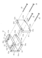
- FIG. 1 is a perspective view schematically showing a bearing of a ball exchange system according to an embodiment.
- FIG. 2 is a cross-sectional view taken along line II-II shown in FIG. It is a disassembled perspective view which briefly shows the connection part which has a transparent part for the light irradiation to a ball
- FIG. 5 is a sectional view taken along line VV shown in FIG. It is a block diagram which shows the monitoring apparatus of a ball
- FIG. 11 is a cross-sectional view schematically showing a state in which a rolling element replacement jig set on a bearing is slid in a direction indicated by a white arrow in FIG. 10.
- FIG. 11 is a cross-sectional view schematically showing replacement of a damaged ball with a new ball after the rolling element replacement jig is slid in the direction indicated by the white arrow in FIG. 10.
- FIG. 1 is a perspective view schematically showing a bearing 1 of a ball exchange system
- FIG. 2 is a sectional view taken along line II-II shown in FIG.
- the circumferential direction, axial direction, and radial direction used in the following description indicate the circumferential direction, axial direction, and radial direction of the bearing 1.
- the bearing 1 includes an inner ring 2, an outer ring 3 surrounding the inner ring 2, and a rollable ball 50 sandwiched between the outer ring 3 and the inner ring 2.
- the ball 50 is an example of a rolling element, and other rolling elements (for example, rollers) may be used.
- Grease (not shown) is supplied around the ball 50.
- a recess 2 a is provided in a part of the outer periphery of the inner ring 2.
- the recess 2a is formed in an arc shape along the circumferential direction.
- the outer ring 3 includes a main body portion 30 that is C-shaped when viewed from the axial direction, and a connecting portion 31 that connects the one end portion 30 a and the other end portion 30 b of the main body portion 30.
- the connecting portion 31 is disposed at a position corresponding to the concave portion 2a.
- the inner ring 2 and the outer ring 3 rotate around the axis within the range of the circumferential dimension of the recess 2a. That is, the inner ring 2 and the outer ring 3 rotate so that the connecting portion 31 is always located in the recess 2a.
- the ball 50 is movable in the circumferential direction, and moves in the circumferential direction when the inner ring 2 or the outer ring 3 is rotated.
- the ball 50 is accommodated inside the outer ring 3, and does not fall into the recess 2 a at a position corresponding to the recess 2 a, but moves in the outer ring 3 or the connecting portion 31 in the circumferential direction.
- FIG. 3 is an exploded perspective view schematically showing the connecting part 31 having a transparent part for light irradiation to the ball 50 and for receiving reflected light from the ball 50
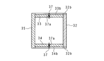
- FIG. 4 is a side sectional view of the connecting part 31.
- the connecting portion 31 is disposed on the outer side in the radial direction, the first side surface portion 33 and the second side surface portion 34 facing in the axial direction of the bearing 1, the third side surface portion 35 disposed on the radially inner side of the bearing 1.
- the first side surface portion 33 to the fourth side surface portion 35 constitute a cover portion that covers both end portions 30a, 30b of the main body portion 30 from four directions in the connecting portion 31 of the bearing 1.
- the first side surface portion 33 has a plate shape extending in the radial direction and the circumferential direction. Insertion holes 33a and 33a through which the bolts 36 are inserted are respectively provided in both ends of the first side surface portion 33 in the circumferential direction.
- first connecting pin 37 (connecting pin) passes through the groove 33b in the axial direction.
- the first connecting pin 37 is provided with an urging member 37a (for example, a spring or rubber), and the urging member 37a urges the first connecting pin 37 in a standing direction.
- urging member 37a for example, a spring or rubber
- Inserted holes 34a and 34a for inserting bolts 36 are provided at both ends in the circumferential direction of the second side surface portion 34 in the radial direction.
- Two grooves 34b and 34b spaced apart in the circumferential direction are provided on the surface of the second side surface portion 34 opposite to the first side surface portion 33.
- the groove 34b extends in the radial direction.
- a first connecting pin 37 passes through the groove 34b in the axial direction.
- the first connecting pin 37 is provided with an urging member 37a, and the urging member 37a urges the first connecting pin 37 in a standing direction. When the first connecting pin 37 is pushed against the urging force, the first connecting pin 37 falls down. A space for standing and lying down is secured around the first connecting pin 37.
- the third side surface portion 35 has a plate shape extending in the axial direction and the circumferential direction. At positions corresponding to the insertion holes 33a and 34a of the third side surface portion 35, screw holes 35a having female screws are respectively provided. The screw hole 35a is provided coaxially with respect to the insertion holes 33a and 34a.
- the transparent part 32 is constituted by a member that transmits light.
- the transparent portion 32 has a plate shape extending in the axial direction and the circumferential direction.
- insertion holes 32a are provided at positions corresponding to the insertion holes 33a and 34a of the first side surface portion 33 and the second side surface portion 34, respectively.
- the insertion hole 32a is provided coaxially with respect to the insertion holes 33a and 34a.
- Bolts 36 are inserted into the insertion holes 32 a, 33 a, 34 a of the transparent part 32, the first side part 33 and the second side part 34, and the inserted bolts 36 are screwed into the screw holes 35 a of the third side part 35. is doing.
- grooves 32b are provided at positions corresponding to the grooves 33b and 34b of the first side surface portion 33 and the second side surface portion 34, respectively.
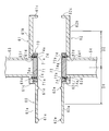
- FIG. 5 is a cross-sectional view taken along the line VV shown in FIG.
- Plate-like door opening / closing jigs 40 corresponding to the rolling element replacement jigs 60 extending in the radial direction and the circumferential direction are respectively provided on one side and the other side of the one end portion 30a.
- the door opening / closing jig 40 is located next to the connecting portion 31.
- the door opening / closing jig 40 is provided with two protruding portions 41, 41 protruding outward in the axial direction and spaced apart in the circumferential direction.
- the protrusion 41 extends in the radial direction.
- the door opening / closing jig 40 and the protruding portion 41 constitute a second release portion.
- FIG. 6 is a block diagram showing a monitoring device of the ball exchange system.
- the monitoring device includes an optical sensor 81 and a control device 100.
- the optical sensor 81 includes an irradiation unit and a light receiving unit.
- the irradiation unit irradiates the ball 50 with light through the transparent portion 32 of the bearing 1.
- the light receiving part receives the reflected light from the ball 50 that has passed through the transparent part 32.
- an irradiation unit and a light receiving unit may be provided separately.
- the irradiation unit is, for example, a light emitting diode, and the light receiving unit is, for example, a photoelectric sensor.
- the control device 100 includes a CPU 101 (Central Processing Unit), a ROM 102 (Read Only Memory), a RAM 103 (Random Access Memory), a nonvolatile memory 104, an input interface (input I / F) 105, and an output interface (output I / F) 106. Etc.
- the CPU 101 includes a timer 101a. The CPU 101 reads the control program stored in the ROM 102 into the RAM 103 and executes monitoring control for the ball 50 of the bearing 1 and ball exchange control for exchanging the ball 50.
- the non-volatile memory 104 stores a table (not shown) indicating a usage time and grease transmittance described later, a threshold value K, a reference waveform, and the like.
- a drive signal and a stop signal are output to the drive device 82 including the shaft fitted to the bearing 1, the supply unit 83 for supplying the ball, and the arm 84.
- a display signal for displaying various information is output from the output interface 106 to the display unit 85.
- the input interface 105 receives a signal indicated by the operation received by the operation unit 80, for example, an operation start signal for starting the operation of the drive device 82.
- the light reflected by the ball 50 is received by the optical sensor 81, and the amount of reflected light detected by the optical sensor 81 is input to the input interface 105.
- FIG. 7A is an example of a graph showing the relationship between the operating time of the bearing 1 before and after the deterioration of the grease and the amount of light reflected from the ball 50 via the grease with respect to the irradiation light (the amount of light received by the optical sensor 81).
- FIG. 7A it is assumed that the wear amount of all the balls 50 is less than a predetermined amount.
- the solid line shows the graph before the grease deteriorates
- the broken line shows the graph after the grease deteriorates.
- the grease supplied around the ball 50 deteriorates as the usage time elapses.
- the grease before deterioration is substantially transparent, but as the deterioration progresses, the hue of the grease gradually becomes darker, for example, reddish black, and the amount of light received decreases.
- the relationship indicating the grease usage time and transmittance is obtained by experiments, and a table (not shown) indicating the grease usage time and transmittance is created based on the experimental results.
- the table is stored in the nonvolatile memory 104, and the CPU 101 corrects the amount of received light with reference to the table.
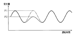
- FIG. 7B shows the operation time of the bearing 1 when the wear amount of the ball 50 is less than the predetermined amount and more than the predetermined amount, and the amount of light reflected from the ball 50 via the grease with respect to the irradiation light (the amount of light received by the optical sensor 81).
- the waveform indicated by the alternate long and short dash line indicates the waveform (hereinafter referred to as the first waveform) when the wear amount of all the balls 50 is less than the predetermined amount, and the waveform indicated by the solid line is at least one.
- a waveform (hereinafter referred to as a second waveform) when the wear amount of one ball 50 is a predetermined amount or more is shown.
- the deviation between the first waveform and the second waveform is greater than a predetermined value.
- the absolute value of the difference between the maximum peak value P1 of the first waveform and the maximum peak value P2 of the second waveform is equal to or greater than the threshold value K.
- FIG. 8 is a flowchart for explaining the monitoring control for the ball 50 of the bearing 1.
- the CPU 101 of the control device 100 determines whether or not an operation start signal is input from the operation unit 80 (step S1). When the operation start signal is not input (step S1: NO), the CPU 101 returns the process to step S1.
- step S1 When an operation start signal is input (step S1: YES), the CPU 101 executes light irradiation and light reception by the optical sensor 81 (step S2), and creates a second waveform (step S3).
- the CPU 101 refers to the first waveform (step S4) and refers to the timer 101a (step S5).
- the timer 101a measures the accumulated operation time after supplying the grease.
- the CPU 101 refers to the table (step S6) and confirms the grease usage time and transmittance.
- the CPU 101 obtains the grease transmittance based on the accumulated operation time measured by the timer 101a and a table indicating the grease usage time and transmittance, and corrects the first waveform referred to in step S4 (step S7). ).
- the cumulative operation time corresponds to the grease usage time.
- the CPU 101 determines whether or not the absolute value of the difference between the maximum peak value P1 of the first waveform and the maximum peak value P2 of the second waveform is greater than or equal to the threshold value K (step S8). If the absolute value of the difference between P1 and P2 is not greater than or equal to K (step S8: NO), the process returns to step S2.
- step S8 When the absolute value of the difference between P1 and P2 is equal to or greater than K (step S8: YES), the CPU 101 outputs a signal indicating an abnormality on the display unit 85 (step S9), and the process is terminated.
- the display unit 85 displays information indicating abnormality, for example, the presence of a worn ball 50.
- FIG. 9 is a cross-sectional view schematically showing the rolling element replacement jig 60.
- the rolling element replacement jig 60 covers one side surface of the outer ring 3 and is opposed to the first cover plate 61 having an arc shape and the first cover plate 61, covers the other side surface of the outer ring 3, and has an arc shape. And a second covering plate 62 formed.
- the first cover plate 61 is adjacent to the first attachment plate 61a attached to the connecting portion 31 and the first attachment plate 61a in the circumferential direction (left-right direction in FIG. 9). 41 (2nd cancellation
- the first mounting plate 61a extends in the circumferential direction.
- a protrusion 61e that protrudes toward the second cover plate 62 and extends in the radial direction (front and back direction in FIG. 9) is provided. Yes.
- the two protrusions 61e are separated in the circumferential direction.
- the second mounting plate 61b extends in the circumferential direction, and both end portions of the second mounting plate 61b protrude to the second covering plate 62 side, and locking portions 61c for locking the slider 70 described later are provided. ing.
- the protruding end portion of the locking portion 61c located on the first mounting plate 61a side is continuous with the first mounting plate 61a.
- the second mounting plate 61 b is provided with a discharge passage 63 that protrudes from the second mounting plate 61 b to the opposite side of the second covering plate 62 and discharges the balls 50.
- the discharge passage 63 includes an opening 63f that penetrates the second mounting plate 61b.
- On the surface of the second mounting plate 61b facing the second cover plate 62 grooves 61d extending in the radial direction are provided on both sides of the opening 63f in the circumferential direction.
- the second cover plate 62 is adjacent to the third attachment plate 62a attached to the connecting portion 31 and the third attachment plate 62a in the circumferential direction, and the door opening / closing jig 40 and the protruding portion 41 (second release portion). And a fourth mounting plate 62b attached to the head.
- the third mounting plate 62a extends in the circumferential direction. On the surface of the third mounting plate 62a that faces the first cover plate 61, a protrusion 62e that protrudes toward the first cover plate 61 and extends in the radial direction is provided. The two protrusions 62e and 62e are separated in the circumferential direction.
- the fourth mounting plate 62b extends in the circumferential direction, and both end portions of the fourth mounting plate 62b protrude toward the first cover plate 61, and locking portions 62c for locking the slider 70 described later are provided. ing.
- the protruding end of the locking portion 62c located on the third mounting plate 62a side is continuous with the third mounting plate 62a.
- the fourth mounting plate 62b is provided with a supply passage 64 that projects from the fourth mounting plate 62b to the opposite side of the first covering plate 61 and supplies the balls 50.
- the supply passage 64 includes an opening 64f that penetrates the fourth mounting plate 62b.
- grooves 62d extending in the radial direction are provided on both sides of the opening 64f in the circumferential direction.
- the first mounting plate 61a and the third mounting plate 62a face each other in the axial direction (vertical direction in FIG. 9), and the second mounting plate 61b and the fourth mounting plate 62b face each other in the axial direction.
- the slider 70 is slidably provided between the second mounting plate 61b and the fourth mounting plate 62b.
- the central portion of the slider 70 is disposed at a circumferential position corresponding to the central portion of the discharge passage 63 or the supply passage 64.
- the slider 70 includes a first sliding plate 71, a second sliding plate 72, and a third sliding plate.
- the first sliding plate 71 is provided on the surface of the second mounting plate 61b that faces the second cover plate 62.
- the first sliding plate 71 includes two grooves 71a and 71a (second grooves) that are separated in the circumferential direction and extend in the radial direction. The positions of the two grooves 71a correspond to the positions of the two grooves 61d of the second mounting plate 61b. As shown in FIG.
- the second connecting pin 74 passes through the groove 71a of the first sliding plate 71 in the axial direction. As shown in FIG. 9, the second linking pin 74 is provided with a second urging member 74a, and the second linking member 74a is urged in the standing direction by the second urging member 74a. Yes. When the second connecting pin 74 is pushed against the urging force, the first connecting pin 37 falls.
- the second connecting pin 74 is erected in the axial direction, and in the erected state, one end portion thereof is located in the groove 61d of the second mounting plate 61b, and the other end portion thereof is located in the groove 71a of the first sliding plate 71. is doing.
- the second connecting pin 74 restricts the relative circumferential movement of the first sliding plate 71 and the second mounting plate 61b.
- the second connecting pin 74 connects the first sliding plate 71 and the second mounting plate 61b.
- the first sliding plate 71 closes the discharge passage 63 at the initial position.
- the second sliding plate 72 is provided on the surface of the fourth mounting plate 62b facing the first frame.
- the second sliding plate 72 includes two grooves 72a and 72a that are spaced apart from each other in the circumferential direction and extend in the radial direction.
- the positions of the two grooves 72a correspond to the positions of the two grooves 62d of the fourth mounting plate 62b.
- the position of the groove 72a of the second sliding plate 72 and the fourth mounting plate The position of the groove 62d of 62b is substantially the same in the circumferential direction.
- the second connecting pin 74 passes through the groove 72a of the second sliding plate 72 in the axial direction. As shown in FIG. 9, the second linking pin 74 is provided with a second urging member 74a, and the second linking member 74a is urged in the standing direction by the second urging member 74a. Yes. When the second connecting pin 74 is pushed against the urging force, the first connecting pin 37 falls.
- the second connecting pin 74 is erected in the axial direction, and in the erected state, one end portion thereof is located in the groove 62d of the fourth mounting plate 62b, and the other end portion thereof is located in the groove 72a of the second sliding plate 72. is doing.
- the second connecting pin 74 restricts the relative circumferential movement of the second sliding plate 72 and the fourth mounting plate 62b.
- the second connecting pin 74 connects the second sliding plate 72 and the fourth mounting plate 62b.
- the second sliding plate 72 closes the supply passage 64 in the initial position.
- the first mounting plate 61a, the third mounting plate 62a, and the protrusions 61e and 62e constitute a release mechanism and a release portion.
- the circumferential dimension D1 between the central portion of the third mounting plate 62a (or the first mounting plate 61a) and the central portion of the discharge passage 63 (or the supply passage 64), and the center of the discharge passage 63 (or the supply passage 64) is substantially the same.
- the CPU 101 When there is a worn ball 50 on the outer ring 3 (hereinafter, the worn ball 50 is referred to as an old ball 52), the CPU 101 outputs a drive signal to the drive device 82, positions the old ball 52 at the connecting portion 31, and The ball 52 is replaced with a new ball 51.
- FIG. 10 is a perspective view schematically showing the bearing 1 immediately after the rolling element replacement jig 60 is attached
- FIG. 11A is a cross-sectional view schematically showing the rolling element replacement jig 60 immediately after being set on the bearing
- FIG. 11C is a cross-sectional view schematically showing a state in which the rolling element replacement jig 60 set on the bearing is slid in the direction indicated by the white arrow in FIG. 10, and FIG. 11C is the rolling element in the direction indicated by the white arrow in FIG.
- the four first connecting pins 37 and the four second connecting pins 7 are laid down at the same time when the rolling element replacement jig 60 is attached to the bearing 1, and the release portion And the 2nd cancellation
- tool 60 can be slid with respect to a bearing in the direction of the white arrow of FIG.
- the slide of the rolling element replacement jig 60 allows the damaged old ball 52 to escape upward in FIG. 11B and a passage for inserting the new ball 51 from below is secured. Then, as shown in FIG. 11C, the old ball 52 is replaced with a new ball 51.
- the CPU 101 outputs a drive signal to the arm 84 and attaches the rolling element replacement jig 60 to the bearing 1 by the arm 84.
- the protrusions 61e and 62e of the first mounting plate 61a and the third mounting plate 62a are inserted into the grooves 33b and 34b of the first side surface portion 33 and the second side surface portion 34, respectively.
- the protrusions 61e and 62e cause the first connecting pin 37 to fall down against the urging force of the urging member 37a, and release the connection between the connecting portion 31 and the main body portion 30.
- the connection part 31 and the main-body part 30 can move relatively in the circumferential direction.
- the protruding portion 41 protruding from the door opening / closing jig 40 is inserted into the grooves of the first sliding plate 71 and the second sliding plate 72.
- the protruding portion 41 resists the urging force of the second urging member 74 a to cause the second connecting pin 74 to fall down and release the connection between the slider 70 and the first cover plate 61 and the second cover plate 62.
- the slider 70, the first cover plate 61, and the second cover plate 62 are relatively movable in the circumferential direction.
- the slider 70 is disposed at a position corresponding to the central portion of the supply passage 64. A new ball 51 is supplied to the supply passage 64.
- the CPU 101 outputs a drive signal to the arm 84 and slides the rolling element replacement jig 60 toward the connecting portion 31 (left side in FIG. 11B).
- the connecting portion 31 slides relative to the main body portion 30 and moves.
- the second mounting plate 61b and the fourth mounting plate 62b slide relative to the slider 70 and move.
- the slider 70 is locked to the locking portion 61c on the opposite side of the connecting portion 31, and the rolling element replacement jig 60 stops. By the movement of the slider 70, the closed discharge passage 63 and supply passage 64 are opened.
- the central part of the slider 70 is located on the opposite side of the discharge passage 63 in the fourth mounting plate 62b. That is, the slider 70 relatively moves the distance D2 in the circumferential direction.
- the old ball 52 is located between the second mounting plate 61 b and the fourth mounting plate 62 b and between the discharge passage 63 and the supply passage 64. That is, the old ball 52 moves a distance D1 relatively in the circumferential direction.
- a space in which the ball 50 can move in the axial direction is formed between the one end portion 30a and the other end portion sentence 30b.
- the width of the space is slightly larger than the diameter of the ball 50.
- the width of the discharge passage 63 and the supply passage 64 is also slightly larger than the diameter of the ball 50, and the ball 50 can move through the space, the discharge passage 63 and the supply passage 64 one by one.
- the CPU 101 outputs a drive signal to the supply unit 83.
- the supply unit 83 supplies the new ball 51 to the supply passage 64.
- the old ball 52 is pushed out into the discharge passage 63 by the supplied new ball 51, and as shown by the arrow in FIG. A new ball 51 is supplied between the end portions 30b. In other words, the old ball 52 and the new ball 51 are exchanged.
- the CPU 101 automatically attaches the rolling element replacement jig 60 and replaces the balls.
- it may be replaced manually. That is, the user may replace the ball 50 by attaching the rolling element replacement jig 60 to the bearing 1 and operating the supply unit 83.
- the ball 50 is irradiated with light through the transparent portion 32. Based on the amount of reflected light from the ball 50, the degree of wear for each ball 50 can be calculated. Further, only the ball 50 whose wear degree exceeds the allowable value can be replaced, and it is not necessary to replace the entire bearing 1.
- the bearing 1 when the bearing 1 is used for a long time, the grease located around the ball 50 deteriorates and the light transmittance also decreases.
- the degree of wear of the ball 50 when the degree of wear of the ball 50 is calculated, correction according to the usage time of the bearing 1 can be performed.
- connection of the main body part 30 by the connection part 31 is released, the connection part 31 is moved, and the rolling element replacement jig 60 (ball replacement part) is positioned between the both end portions 30 a and 30 b of the main body part 30.
- the old ball 52 positioned between the both end portions 30 a and 30 b is replaced with a new ball 51 by the rolling element replacement jig 60.
- the first connecting pin 37 is laid down to release the connection between both end portions 30a and 30b of the main body 30. Further, the protrusions 61e and 62e (release mechanism, release portion) are inserted into the groove 34b, and the first connecting pin 37 is lowered.
- the second connecting pin 74 is laid down to release the connection between the first cover plate 61 and the second cover plate 62 and the slider 70. Further, by interlocking the collapse of the first connecting pin 37 and the second connecting pin 74, the relative movement between the first cover plate 61 and the second cover plate 62 and the slider 70, and the main body portion 30 and the connecting portion 31. Relative movement can be realized simultaneously.
- the ball 50 can be replaced simply by attaching the rolling element replacement jig 60 to the bearing 1 and sliding it in the circumferential direction. Therefore, the ball 50 can be easily replaced not only automatically but also manually.
- the protrusion 41 (second release portion) is inserted into the groove 71a (second groove) to realize the fall of the second connecting pin 74.
- the transparent part 32 of the connecting part 31 is transparent, but other parts may be configured to be transparent. That is, in the connection part 31, you may comprise the transparent part 32 and all or one part of another part transparently. Moreover, you may comprise the main-body part 30 and the connection part 31 whole transparently.
- step S8 in order to determine whether or not the wear amount of the ball 50 is greater than or equal to a predetermined amount, the absolute value of the difference between the minimum peak value of the first waveform and the minimum peak value of the second waveform and a predetermined threshold value are determined. To determine whether the absolute value is greater than or equal to the threshold value.
Landscapes
- Engineering & Computer Science (AREA)
- General Engineering & Computer Science (AREA)
- Mechanical Engineering (AREA)
- Physics & Mathematics (AREA)
- General Physics & Mathematics (AREA)
- Rolling Contact Bearings (AREA)
Abstract
短時間でベアリングを修理することができる監視装置、転動体交換システム、交換装置及びベアリングを提供する。 ベアリングの転動体の摩耗度合いを監視する監視装置であって、前記ベアリングの少なくとも一部は透明部によって構成されており、前記透明部に光を照射する照射部と、前記透明部を通過した前記転動体からの反射光を受光する受光部と、該受光部にて受光した光量に基づいて、前記転動体の摩耗度合いを演算する演算部とを備えることを特徴とする監視装置。
Description
本技術は、ベアリングの転動体の摩耗度合いを監視する監視装置、転動体交換システム、交換装置及びベアリングに関する。
従来、減速機の故障診断装置が提案されている(特許文献1参照)。減速機はベアリングを備えており、故障診断装置は、ベアリングのボール(転動体)の周囲に設けられたグリスに含まれる鉄粉含有量を検出し、ボールの摩耗量を演算している。ボールの摩耗量が許容値を超過した場合に、ユーザはベアリングを交換することができる。
しかし、ベアリングの交換には長時間を要する。
本実施例は係る事情に鑑みてなされたものであり、短時間で修理することができる監視装置、転動体交換システム、交換装置及びベアリングを提供することを目的とする。
本実施例に係る監視装置は、ベアリングの転動体の摩耗度合いを監視する監視装置であって、前記ベアリングの少なくとも一部は透明部によって構成されており、前記透明部に光を照射する照射部と、前記透明部を通過した前記転動体からの反射光を受光する受光部と、該受光部にて受光した光量に基づいて、前記転動体の摩耗度合いを演算する演算部とを備えることを特徴とする。
透明部を介して、光を転動体に照射する。転動体からの反射光の光量に基づいて、転動体毎の摩耗度合いを演算することができる。また摩耗度合いが許容値を超過した転動体だけを交換することができ、ベアリング全体を交換する必要がない。
以下実施の形態に係るボール交換システムを図面に基づいて説明する。図1は、ボール交換システムのベアリング1を略示する斜視図、図2は、図1に示すII-II線を切断線とした断面図である。以下の説明において使用する周方向、軸方向及び径方向は、ベアリング1の周方向、軸方向及び径方向を示す。
ベアリング1は、内輪2と、該内輪2を囲む外輪3と、該外輪3及び内輪2の間にて狭持された転動可能なボール50とを備える。なおボール50は転動体の一例であり、他の転動体(例えばローラ)を使用してもよい。ボール50の周囲にはグリス(図示略)が供給されている。内輪2の外周の一部に凹部2aが設けられている。凹部2aは、周方向に沿って円弧状に形成されている。
外輪3は、軸方向から視認した場合にC状をなす本体部30と、該本体部30の一端部分30a及び他端部分30bを連結する連結部31とを備える。連結部31は、前記凹部2aに対応した位置に配されている。内輪2及び外輪3は、前記凹部2aの周方向寸法の範囲内において、軸回りに回転する。すなわち、内輪2及び外輪3は、連結部31が常時凹部2a内に位置するように、回転する。
ボール50は周方向に移動可能であり、内輪2又は外輪3の回転時に周方向に移動する。ボール50は、外輪3の内側に収容されており、前記凹部2aに対応する位置において、凹部2a内に落下せず、外輪3又は連結部31内を周方向に移動する。
図3は、ボール50への光照射及びボール50からの反射光受講の為に透明部を有した連結部31を略示する分解斜視図、図4は、連結部31の側面断面図である。連結部31は、ベアリング1の軸方向に対向した第1側面部33及び第2側面部34と、ベアリング1の径方向内側に配置された第3側面部35と、径方向外側に配置された透明部32とを備える。第1側面部33~第4側面部35は、ベアリング1の連結部31において、本体部30の両端部分30a、30bを4方向から覆うカバー部を構成する。第1側面部33は径方向及び周方向に延びた板状をなす。第1側面部33の周方向両端部に、径方向に貫通しており、ボルト36を挿入する挿入孔33a、33aがそれぞれ設けられている。
第1側面部33における第2側面部34の反対側の面には、周方向に離隔した二つの溝33b、33bが設けられている。溝33bは径方向に延びている。前記溝33bを、第1連結ピン37(連結ピン)が軸方向に貫通している。図4に示すように、第1連結ピン37には、付勢部材37a(例えばばね又はゴム)が設けられており、付勢部材37aによって、第1連結ピン37は、起立する方向に付勢されている。付勢力に抗して第1連結ピン37を押した場合、第1連結ピン37は倒伏する。なお力が付与されていない場合、付勢部材37aの付勢力によって第1連結ピン37は軸方向に起立する。
第2側面部34の周方向両端部に、径方向に貫通しており、ボルト36を挿入する挿入孔34a、34aがそれぞれ設けられている。第2側面部34における第1側面部33の反対側の面には、周方向に離隔した二つの溝34b、34bが設けられている。溝34bは径方向に延びている。前記溝34bを、第1連結ピン37が軸方向に貫通している。第1連結ピン37には、付勢部材37aが設けられており、付勢部材37aによって、第1連結ピン37は、起立する方向に付勢されている。付勢力に抗して第1連結ピン37を押した場合、第1連結ピン37は倒伏する。なお第1連結ピン37の周囲には、起立及び倒伏するための空間が確保されている。
第3側面部35は、軸方向及び周方向に延びた板状をなす。第3側面部35の前記挿入孔33a、34aに対応した位置には、雌ねじを有するねじ孔35aがそれぞれ設けられている。ねじ孔35aは、挿入孔33a、34aに対して同軸的に設けられている。
透明部32は光を透過する部材によって構成されている。透明部32は、軸方向及び周方向に延びた板状をなす。透明部32において、第1側面部33及び第2側面部34の挿入孔33a、34aに対応した位置に、挿入孔32aがそれぞれ設けられている。該挿入孔32aは、前記挿入孔33a、34aに対して同軸的に設けられている。透明部32、第1側面部33及び第2側面部34の挿入孔32a、33a、34aにボルト36が挿入されており、挿入されたボルト36は第3側面部35のねじ孔35aに螺合している。透明部32において、第1側面部33及び第2側面部34の溝33b、34bに対応した位置に、溝32bがそれぞれ設けられている。
図5は、図1に示すV-V線を切断線とした断面図である。前記一端部分30aの軸方向一側及び他側に、径方向及び周方向に延びる転動体交換治具60に対応した板状の扉開閉治具40がそれぞれ設けられている。扉開閉治具40は連結部31の隣に位置する。扉開閉治具40には、軸方向外向きに突出しており、周方向に離隔した二つの突出部41、41が設けられている。突出部41は径方向に延びる。なお扉開閉治具40及び突出部41は第2解除部を構成する。
図6は、ボール交換システムの監視装置を示すブロック図である。監視装置は、光センサ81及び制御装置100を備える。光センサ81は、照射部及び受光部を備える。照射部は、ベアリング1の透明部32を通してボール50に光を照射する。受光部は、透明部32を通過したボール50からの反射光を受光する。なお光センサ81に代えて、照射部及び受光部を別に設けてもよい。照射部は、例えば発光ダイオードであり、受光部は、例えば光電センサである。
制御装置100は、CPU101(Central Processing Unit)、ROM102(Read Only Memory)、RAM103(Random Access Memory)、不揮発性メモリ104、入力インタフェース(入力I/F)105及び出力インタフェース(出力I/F)106等を備える。CPU101はタイマ101aを備える。CPU101は、ROM102に格納した制御プログラムをRAM103に読み込んで、ベアリング1のボール50に対する監視制御及びボール50を交換するボール交換制御等を実行する。
不揮発性メモリ104には、後述する使用時間及びグリスの透過率を示すテーブル(図示略)、閾値K、基準波形等が記憶されている。
出力インタフェース106からは、ベアリング1に嵌合する軸を含む駆動装置82、ボールを供給する供給部83及びアーム84に、駆動信号及び停止信号が出力される。また出力インタフェース106からは、種々の情報を表示する表示信号が表示部85に出力される。
入力インタフェース105には、操作部80にて受け付けた操作が示す信号、例えば駆動装置82の運転を開始する運転開始信号が入力される。ボール50にて反射した光は光センサ81にて受光され、入力インタフェース105には、光センサ81にて検出された反射光の光量が入力される。
ベアリング1の運転時間と照射光に対するグリスを介したボール50からの反射光量(光センサ81の受光量)との関係は、例えば波形によって示される。図7Aは、グリスの劣化前後におけるベアリング1の運転時間と照射光に対するグリスを介したボール50からの反射光量(光センサ81の受光量)との関係を示すグラフの一例である。なお図7Aにおいて、全てのボール50の摩耗量は所定量未満であるとする。
実線は、グリスが劣化する前のグラフを示し、破線は、グリスが劣化した後のグラフを示す。ボール50の周囲に供給されたグリスは、使用時間が経過するに従って、劣化する。劣化前のグリスは略透明であるが、劣化が進行するに従って、グリスの色相は徐々に濃くなり、例えば赤黒くなり、光の受光量が低下する。
グリスの使用時間及び透過率を示す関係は、実験によって求められ、実験結果に基づいて、グリスの使用時間及び透過率を示すテーブル(図示略)が作成される。前述したように、テーブルは不揮発性メモリ104に記憶されており、CPU101は、テーブルを参照して、受光量を補正する。
図7Bは、ボール50の摩耗量が所定量未満及び所定量以上である場合におけるベアリング1の運転時間と照射光に対するグリスを介したボール50からの反射光量(光センサ81の受光量)との関係を示すグラフの一例である。図7Bにおいて、一点鎖線にて示された波形は、全てのボール50の摩耗量が所定量未満の場合における波形(以下第1波形という)を示し、実線にて示された波形は、少なくとも一つのボール50の摩耗量が所定量以上である場合における波形(以下第2波形という)を示す。
ボール50の摩耗量が所定量以上である場合、第1波形及び第2波形間の偏差が所定値よりも大きくなる。例えば、第1波形の最大ピーク値P1と、第2波形の最大ピーク値P2との差分の絶対値が閾値K以上となる。
図8は、ベアリング1のボール50に対する監視制御を説明するフローチャートである。制御装置100のCPU101は、操作部80から運転開始信号が入力されたか否かを判定する(ステップS1)。運転開始信号が入力されていない場合(ステップS1:NO)、CPU101は、ステップS1に処理を戻す。
運転開始信号が入力された場合(ステップS1:YES)、CPU101は光センサ81による光の照射及び受光を実行し(ステップS2)、第2波形を作成する(ステップS3)。CPU101は第1波形を参照し(ステップS4)、タイマ101aを参照する(ステップS5)。なおタイマ101aは、グリス供給後の累積運転時間を計測している。
CPU101は、テーブルを参照し(ステップS6)、グリスの使用時間及び透過率を確認する。CPU101は、タイマ101aにて計測した累積運転時間と、グリスの使用時間及び透過率を示すテーブルとに基づいて、グリスの透過率を求め、ステップS4で参照した第1波形を補正する(ステップS7)。なお累積運転時間は、グリスの使用時間に相当する。
CPU101は、第1波形の最大ピーク値P1と、第2波形の最大ピーク値P2との差分の絶対値が閾値K以上であるか否かを判定する(ステップS8)。P1及びP2の差分の絶対値がK以上でない場合(ステップS8:NO)、ステップS2に処理を戻す。
P1及びP2の差分の絶対値がK以上である場合(ステップS8:YES)、CPU101は表示部85に異常を表示する信号を出力し(ステップS9)、処理を終了する。表示部85は、異常を示す情報、例えば摩耗したボール50の存在を表示する。
P1及びP2の差分の絶対値がK以上である場合、転動体交換治具60(移動機構、ボール交換部)をベアリング1に取り付けて、摩耗したボール50を交換することができる。図9は、転動体交換治具60を略示する断面図である。
転動体交換治具60は、外輪3の一側面を覆い、円弧状をなす第1被覆板61と、該第1被覆板61に対向しており、外輪3の他側面を覆い、円弧状をなす第2被覆板62とを備える。第1被覆板61は、連結部31に取り付けられる第1取付板61aと、周方向(図9の左右方向)にて第1取付板61aに隣接しており、扉開閉治具40及び突出部41(第2解除部)に取り付けられる第2取付板61bとを備える。
第1取付板61aは周方向に延びる。第1取付板61aにおける第2被覆板62に対向する面には、第2被覆板62に向けて突出しており、径方向(図9の表裏方向)に延びた突条61eがそれぞれ設けられている。二つの突条61eは周方向に離隔している。
第2取付板61bは周方向に延びており、第2取付板61bの両端部には、第2被覆板62側に突出しており、後述するスライダ70を係止する係止部61cが設けられている。第1取付板61a側に位置する係止部61cの突出端部は第1取付板61aに連なっている。第2取付板61bには、第2取付板61bから第2被覆板62の反対側に突出しており、ボール50を排出する排出通路63が設けられている。
排出通路63は、第2取付板61bを貫通した開口63fを備える。第2取付板61bの第2被覆板62に対向する面には、周方向における開口63fの両隣それぞれに径方向に延びた溝61dが設けられている。
第2被覆板62は、連結部31に取り付けられる第3取付板62aと、周方向にて第3取付板62aに隣接しており、扉開閉治具40及び突出部41(第2解除部)に取り付けられる第4取付板62bとを備える。
第3取付板62aは周方向に延びる。第3取付板62aにおける第1被覆板61に対向する面には、第1被覆板61に向けて突出しており、径方向に延びた突条62eがそれぞれ設けられている。二つの突条62e、62eは周方向に離隔している。
第4取付板62bは周方向に延びており、第4取付板62bの両端部には、第1被覆板61側に突出しており、後述するスライダ70を係止する係止部62cが設けられている。第3取付板62a側に位置する係止部62cの突出端部は第3取付板62aに連なっている。第4取付板62bには、第4取付板62bから第1被覆板61の反対側に突出しており、ボール50を供給する供給通路64が設けられている。
供給通路64は、第4取付板62bを貫通した開口64fを備える。第4取付板62bの第1被覆板61に対向する面には、周方向における開口64fの両隣それぞれに径方向に延びた溝62dが設けられている。第1取付板61aと第3取付板62aとは軸方向(図9の上下方向)に対向し、第2取付板61bと第4取付板62bとは軸方向に対向する
第2取付板61bと第4取付板62bとの間にスライダ70が摺動可能に設けられている。スライダ70の中央部は、排出通路63又は供給通路64の中央部分に対応する周方向位置に配されている。スライダ70は、第1摺動板71、第2摺動板72及び第3摺動板を備える。第1摺動板71は、第2取付板61bの第2被覆板62に対向する面に設けられている。第1摺動板71は、周方向に離隔しており、径方向に延びた二つの溝71a、71a(第2溝)を備える。この二つの溝71aの位置は第2取付板61bの二つの溝61dの位置に対応している。図9に示すように、第1取付板61a側において第1摺動板71が係止部61cに係止している場合に、第1摺動板71の溝71aの位置と第2取付板61bの溝61dの位置は、周方向において略同じになる。
第1摺動板71の溝71aを第2連結ピン74が軸方向に貫通している。図9に示すように、第2連結ピン74には、第2付勢部材74aが設けられており、第2付勢部材74aによって、第2連結ピン74は、起立する方向に付勢されている。付勢力に抗して第2連結ピン74を押した場合、第1連結ピン37は倒伏する。
第2連結ピン74は軸方向に起立し、起立した状態において、その一端部が第2取付板61bの溝61d内に位置し、その他端部が第1摺動板71の溝71a内に位置している。起立した状態において、第2連結ピン74は、第1摺動板71及び第2取付板61bの相対的な周方向移動を規制している。換言すれば、第2連結ピン74は第1摺動板71及び第2取付板61bを連結する。第1摺動板71は初期位置において、排出通路63を閉鎖している。
第2摺動板72は、第4取付板62bの第1フレームに対向する面に設けられている。第2摺動板72は、周方向に離隔しており、径方向に延びた二つの溝72a、72aを備える。この二つの溝72aの位置は第4取付板62bの二つの溝62dの位置に対応している。図9に示すように、第3取付板62a側において第2摺動板72が係止部62cに係止している場合に、第2摺動板72の溝72aの位置と第4取付板62bの溝62dの位置は、周方向において略同じになる。
第2摺動板72の溝72aを第2連結ピン74が軸方向に貫通している。図9に示すように、第2連結ピン74には、第2付勢部材74aが設けられており、第2付勢部材74aによって、第2連結ピン74は、起立する方向に付勢されている。付勢力に抗して第2連結ピン74を押した場合、第1連結ピン37は倒伏する。
第2連結ピン74は軸方向に起立し、起立した状態において、その一端部が第4取付板62bの溝62d内に位置し、その他端部が第2摺動板72の溝72a内に位置している。起立した状態において、第2連結ピン74は、第2摺動板72及び第4取付板62bの相対的な周方向移動を規制している。換言すれば、第2連結ピン74は第2摺動板72及び第4取付板62bを連結する。第2摺動板72は初期位置において、供給通路64を閉鎖している。なお第1取付板61a、第3取付板62a及び突条61e、62eは解除機構及び解除部を構成する。
第3取付板62a(又は第1取付板61a)の中央部分と排出通路63(又は供給通路64)の中央部分との間の周方向寸法D1と、排出通路63(又は供給通路64)の中央部分と第4取付板62b(又は第2取付板61b)における供給通路64の反対側部分(図9の右側部分)との間の周方向寸法D2とは略同じである。
外輪3に摩耗したボール50(以下摩耗したボール50を旧ボール52という)が存在する場合、CPU101は、駆動装置82に駆動信号を出力し、旧ボール52を連結部31に位置させて、旧ボール52を新ボール51に交換する。
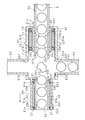
図10は、転動体交換治具60を取り付けた直後のベアリング1を略示する斜視図、図11Aは、ベアリングにセットした直後の転動体交換治具60を略示する断面図、図11Bは、ベアリングにセットした転動体交換治具60を、図10の白抜き矢印が示す向きにスライドさせた状態を略示する断面図、図11Cは、図10の白抜き矢印が示す向きに転動体交換治具をスライドさせた後における、破損したボールと新しいボールとの交換を略示する断面図である。
図10及び図11Aに示すように、4個の第1連結ピン37及び4個の第2連結ピン7は、転動体交換治具60をベアリング1に取り付けた場合に、同時に倒伏され、解除部及び第2解除部が同時に解除され、転動体交換治具60がベアリングに対して、図10の白抜き矢印の方向にスライド可能となる。図11Bに示すように、転動体交換治具60のスライドによって、破損した旧ボール52を図11B中の上方向に逃がし、下から新ボール51を挿入する為の通路が確保される。そして図11Cに示すように、旧ボール52を新ボール51に交換する。
上記旧ボール52及び新ボール51の交換手順を詳細に説明する。図11Aに示すように、まず、CPU101はアーム84に駆動信号を出力し、アーム84によって転動体交換治具60をベアリング1に取り付ける。このとき第1取付板61a及び第3取付板62aの突条61e、62eを、第1側面部33及び第2側面部34の溝33b、34bに挿入する。突条61e、62eは、付勢部材37aの付勢力に抗して、第1連結ピン37を倒伏させ、連結部31と本体部30との連結を解除する。連結部31及び本体部30は、周方向に相対的に移動可能となる。
また扉開閉治具40から突出した突出部41を、第1摺動板71及び第2摺動板72の溝に挿入する。突出部41は、第2付勢部材74aの付勢力に抗して、第2連結ピン74を倒伏させ、スライダ70と、第1被覆板61及び第2被覆板62との連結を解除する。スライダ70と、第1被覆板61及び第2被覆板62とは、周方向に相対的に移動可能となる。スライダ70は、供給通路64の中央部分に対応する位置に配されている。供給通路64には、新ボール51が供給されている。
図10の白抜き矢印及び図11Bの矢印にて示すように、CPU101はアーム84に駆動信号を出力し、転動体交換治具60を連結部31側(図11Bの左側)に摺動させる。連結部31は本体部30に対して摺動し、移動する。第2取付板61b及び第4取付板62bは、スライダ70に対して摺動し、移動する。スライダ70は、連結部31の反対側において、係止部61cに係止し、転動体交換治具60は停止する。スライダ70の移動によって、閉鎖されていた排出通路63及び供給通路64は開放される。
スライダ70の中央部は、第4取付板62bにおける排出通路63の反対側部分に位置する。すなわち、スライダ70は、周方向に、相対的に距離D2移動する。旧ボール52は、第2取付板61b及び第4取付板62bの間、且つ排出通路63及び供給通路64の間に位置する。すなわち、旧ボール52は、周方向に相対的に距離D1移動する。一端部分30a及び他端部文30bの間には、ボール50が軸方向に移動可能な空間が形成される。該空間の幅はボール50の直径よりも若干大きい。排出通路63及び供給通路64の幅も、ボール50の直径よりも若干大きく、ボール50は前記空間、排出通路63及び供給通路64を一つずつ移動することができる。
CPU101は、供給部83に駆動信号を出力する。供給部83は供給通路64に新ボール51を供給する。図11Cの白抜き矢印にて示すように、旧ボール52は、供給された新ボール51によって排出通路63に押し出され、図11Cの矢印にて示すように、本体部30の一端部分30a及び他端部分30bの間に新ボール51が供給される。換言すれば、旧ボール52と新ボール51とが交換される。
旧ボール52を新ボール51に交換した後、図10の白抜き矢印が示す方向とは反対方向に、転動体交換治具60をベアリング1と相対的にスライドさせると、図11Aに示す状態に戻り、第1側面部33及び第2側面部34は、一端部分30a及び他端部分30bを覆う。そして、転動体交換治具60をベアリング1から取り外す。このとき、図5に示すように、上記8箇所のピンが立ちあがり、ベアリング1と、第1側面部33及び第2側面部34それぞれとがロックされる。
なお上述した実施の形態においては、CPU101が転動体交換治具60の取り付け及びボールの交換を自動的に行っているが、手動で交換してもよい。すなわちユーザが転動体交換治具60をベアリング1に取り付けて、供給部83を操作し、ボール50を交換してもよい。
また透明部32を介して、光をボール50に照射する。ボール50からの反射光の光量に基づいて、ボール50毎の摩耗度合いを演算することができる。また摩耗度合いが許容値を超過したボール50だけを交換することができ、ベアリング1全体を交換する必要がない。
またベアリング1を長時間使用した場合、ボール50の周囲に位置するグリスは劣化し、光の透過率も低下する。実施の形態においては、ボール50の摩耗度合いを演算する場合、ベアリング1の使用時間に応じた補正を行うことができる。
また、連結部31による本体部30の連結を解除し、連結部31を移動させて、転動体交換治具60(ボール交換部)を本体部30の両端部分30a、30bの間に位置させる。転動体交換治具60によって、前記両端部分30a、30bの間に位置した旧ボール52を新ボール51に交換する。
また、第1連結ピン37を倒伏させて、本体部30の両端部分30a、30bの連結を解除する。また、溝34bに突条61e、62e(解除機構、解除部)を挿入させて、第1連結ピン37の倒伏を実現する。
また、第2連結ピン74を倒伏させて、第1被覆板61及び第2被覆板62とスライダ70との連結を解除する。また第1連結ピン37及び第2連結ピン74の倒伏を連動させることによって、第1被覆板61及び第2被覆板62とスライダ70との相対的な移動と、本体部30及び連結部31の相対的な移動を同時に実現させることができる。
また転動体交換治具60をベアリング1に取り付けて、周方向にスライドさせるだけで、ボール50の交換ができる。そのため、自動交換のみならず、手動でも容易にボール50を交換することができる。
また、溝71a(第2溝)に突出部41(第2解除部)を挿入させて、第2連結ピン74の倒伏を実現する。
上述した実施の形態においては、連結部31の一部(透明部32)のみが透明であるが、その他の部分も透明に構成してもよい。すなわち、連結部31において、透明部32と、その他の部分の全部又は一部とを透明に構成してもよい。また本体部30及び連結部31全体を透明に構成してもよい。
なおステップS8において、ボール50の摩耗量が所定量以上であるか否かを判定するために、第1波形の最小ピーク値及び第2波形の最小ピーク値の差分の絶対値と、所定の閾値とを比較し、前記絶対値が前記閾値以上であるか否かを判定してもよい。
今回開示した実施の形態は、全ての点で例示であって、制限的なものではないと考えられるべきである。各実施例にて記載されている技術的特徴は互いに組み合わせることができ、本発明の範囲は、請求の範囲内での全ての変更及び請求の範囲と均等の範囲が含まれることが意図される。
1 ベアリング
2 内輪
3 外輪
30 本体部
31 連結部(移動部)
32 透明部
33 第1側面部(カバー部)
34 第2側面部(カバー部)
37a 付勢部材
34b 溝
37 第1連結ピン(連結ピン)
50 ボール
51 新ボール
52 旧ボール
60 転動体交換治具(移動機構、転動体交換部)
61 第1被覆板(被覆部)
61a 第1取付板(解除機構、解除部)
61e 突条(解除機構、解除部)
62 第2被覆板(被覆部)
62a 第3取付板(解除機構、解除部)
62e 突条(解除機構、解除部)
70 スライダ
71a 溝(第2溝)
74 第2連結ピン
74a 第2付勢部材
81 光センサ(照射部、受光部)
100 制御装置(演算部、補正部)
2 内輪
3 外輪
30 本体部
31 連結部(移動部)
32 透明部
33 第1側面部(カバー部)
34 第2側面部(カバー部)
37a 付勢部材
34b 溝
37 第1連結ピン(連結ピン)
50 ボール
51 新ボール
52 旧ボール
60 転動体交換治具(移動機構、転動体交換部)
61 第1被覆板(被覆部)
61a 第1取付板(解除機構、解除部)
61e 突条(解除機構、解除部)
62 第2被覆板(被覆部)
62a 第3取付板(解除機構、解除部)
62e 突条(解除機構、解除部)
70 スライダ
71a 溝(第2溝)
74 第2連結ピン
74a 第2付勢部材
81 光センサ(照射部、受光部)
100 制御装置(演算部、補正部)
Claims (13)
- ベアリングの転動体の摩耗度合いを監視する監視装置であって、
前記ベアリングの少なくとも一部は透明部によって構成されており、
前記透明部に光を照射する照射部と、
前記透明部を通過した前記転動体からの反射光を受光する受光部と、
該受光部にて受光した光量に基づいて、前記転動体の摩耗度合いを演算する演算部と
を備えることを特徴とする監視装置。 - 前記ベアリングの使用時間に応じて、前記演算部にて演算される前記転動体の摩耗度合いを補正する補正部を備えること
を特徴とする請求項1に記載の監視装置。 - 請求項1又は2に記載の監視装置を備え、
前記ベアリングの外輪は、
前記転動体を収容しており、C状をなす本体部と、
該本体部の両端部分を連結しており、前記透明部を含む連結部と
を有し、
前記連結部による連結を解除する解除機構と、
該解除機構にて連結を解除された前記連結部及び本体部を周方向に相対的に移動させる移動機構と、
前記本体部の両端部分の間にて転動体を交換する転動体交換部と
を備えることを特徴とする転動体交換システム。 - 前記連結部は、
前記本体部の両端部分を覆うカバー部と、
該カバー部を貫通して、前記両端部分それぞれ及び前記カバー部を連結しており、付勢部材によって起立した倒伏可能な複数の連結ピンと
を有し、
前記移動機構は、
前記カバー部及び本体部を覆う被覆部と、
前記本体部の一端部分に連結され、前記被覆部に対して、前記ベアリングの周方向に相対的に摺動可能なスライダと
を有し、
前記解除機構は、
前記被覆部に設けられており、前記連結ピンを前記付勢部材の付勢力に抗して倒伏させて、前記カバー部及び両端部分の連結を解除する解除部を有すること
を特徴とする請求項3に記載の転動体交換システム。 - 前記カバー部は、前記ベアリングの径方向に延びた溝を有し、
前記連結ピンは前記溝を前記ベアリングの軸方向に貫通しており、
前記解除部が前記溝に挿入されて、前記連結ピンが倒伏すること
を特徴とする請求項4に記載の転動体交換システム。 - 前記移動機構は、前記スライダを貫通して、前記被覆部及びスライダを連結しており、第2付勢部材によって起立した倒伏可能な第2連結ピンを有し、
前記第2付勢部材の付勢力に抗して前記第2連結ピンを倒伏させて、前記被覆部及びスライダの連結を解除する第2解除部が前記本体部に設けられており、
前記連結ピン及び第2連結ピンの倒伏は連動していること
を特徴とする請求項4又は5に記載の転動体交換システム。 - 前記スライダは、前記ベアリングの径方向に延びた第2溝を有し、
前記第2連結ピンは前記第2溝を前記ベアリングの軸方向に貫通しており、
前記第2解除部が前記第2溝に挿入されて、前記第2連結ピンが倒伏すること
を特徴とする請求項6に記載の転動体交換システム。 - 前記移動機構を前記ベアリングに装着した場合に、前記連結ピンによる前記両端部分及びカバー部の連結と、前記第2連結ピンによる前記被覆部及びスライダの連結とが同時的に解除されること
を特徴とする請求項6又は7に記載の転動体交換システム。 - 前記転動体交換部は、転動体を供給する供給通路及び転動体を排出する排出通路を有し、
前記スライダは、初期位置にて前記供給通路及び排出通路を閉鎖しており、
前記移動機構を前記ベアリングに装着した後、前記移動機構を前記ベアリングの周方向に沿って一方向に移動させた場合に、前記連結部は移動して前記両端部分の間に空間が形成され且つ前記スライダが移動して前記供給通路及び排出通路を開放し、
前記移動機構を前記ベアリングの周方向に沿って他方向に移動させた場合に、前記連結部は移動して前記両端部分を連結し且つ前記スライダが移動して前記供給通路及び排出通路を閉鎖すること
を特徴とする請求項8に記載の転動体交換システム。 - ベアリングの転動体を交換する交換装置であって、
前記ベアリングの外輪は、
前記転動体を収容しており、C状をなす本体部と、
該本体部の両端部分を連結しており、前記透明部を含む連結部と
を有し、
前記連結部による連結を解除する解除機構と、
該解除機構にて連結を解除された前記連結部及び本体部を周方向に相対的に移動させる移動機構と、
該移動機構に設けられており、前記本体部の両端部分の間にて転動体を交換する転動体交換部と
を備えることを特徴とする交換装置。 - 転動体を収容しており、外輪の少なくとも一部が透明な部材によって構成されていること
を特徴とするベアリング。 - 前記外輪は周方向に移動可能な移動部を有しており、
前記移動部が周方向に移動した場合、前記転動体が軸方向に移動可能な空間が形成されること
を特徴とする請求項11に記載のベアリング。 - 前記移動部をロックするロック部を有し、
転動体を交換する交換装置を前記ベアリングに取り付けた場合に、前記ロック部によるロックが解除されること
を特徴とする請求項12に記載のベアリング。
Priority Applications (1)
| Application Number | Priority Date | Filing Date | Title |
|---|---|---|---|
| PCT/JP2015/085419 WO2017104057A1 (ja) | 2015-12-17 | 2015-12-17 | 監視装置、転動体交換システム、交換装置及びベアリング |
Applications Claiming Priority (1)
| Application Number | Priority Date | Filing Date | Title |
|---|---|---|---|
| PCT/JP2015/085419 WO2017104057A1 (ja) | 2015-12-17 | 2015-12-17 | 監視装置、転動体交換システム、交換装置及びベアリング |
Publications (1)
| Publication Number | Publication Date |
|---|---|
| WO2017104057A1 true WO2017104057A1 (ja) | 2017-06-22 |
Family
ID=59056197
Family Applications (1)
| Application Number | Title | Priority Date | Filing Date |
|---|---|---|---|
| PCT/JP2015/085419 Ceased WO2017104057A1 (ja) | 2015-12-17 | 2015-12-17 | 監視装置、転動体交換システム、交換装置及びベアリング |
Country Status (1)
| Country | Link |
|---|---|
| WO (1) | WO2017104057A1 (ja) |
Citations (4)
| Publication number | Priority date | Publication date | Assignee | Title |
|---|---|---|---|---|
| JPH0285518A (ja) * | 1988-09-22 | 1990-03-27 | Nikkiso Co Ltd | ベアリングモニタ |
| JP2005069288A (ja) * | 2003-08-21 | 2005-03-17 | Nsk Ltd | 転がり軸受内部のグリース封入状態検査方法 |
| JP2010196760A (ja) * | 2009-02-24 | 2010-09-09 | Nsk Ltd | グリース挙動観察方法及び転がり軸受 |
| JP2010286069A (ja) * | 2009-06-12 | 2010-12-24 | Nsk Ltd | 転がり軸受の観察方法 |
-
2015
- 2015-12-17 WO PCT/JP2015/085419 patent/WO2017104057A1/ja not_active Ceased
Patent Citations (4)
| Publication number | Priority date | Publication date | Assignee | Title |
|---|---|---|---|---|
| JPH0285518A (ja) * | 1988-09-22 | 1990-03-27 | Nikkiso Co Ltd | ベアリングモニタ |
| JP2005069288A (ja) * | 2003-08-21 | 2005-03-17 | Nsk Ltd | 転がり軸受内部のグリース封入状態検査方法 |
| JP2010196760A (ja) * | 2009-02-24 | 2010-09-09 | Nsk Ltd | グリース挙動観察方法及び転がり軸受 |
| JP2010286069A (ja) * | 2009-06-12 | 2010-12-24 | Nsk Ltd | 転がり軸受の観察方法 |
Similar Documents
| Publication | Publication Date | Title |
|---|---|---|
| ITFI20140056U1 (it) | Gradino estraibile. | |
| EP2896564B1 (en) | Linear electromechanical actuator and anti-jamming device | |
| ITTO960140A1 (it) | Dispositivo per il controllo dell'orientamento del riflettore mobile di un proiettore per autoveicoli | |
| US11859939B2 (en) | Air gun with automatic cocking | |
| US10480548B2 (en) | Hydraulic actuator to which limit-adjustable mechanical lock device is applied | |
| ITPN20110085A1 (it) | Reggi piano a scomparsa | |
| ITBO980563A1 (it) | Cerniera regolabile per infissi . | |
| IT201900005614A1 (it) | Metodo di rilevazione dello stato di usura di un attuatore elettrico | |
| US20170056953A1 (en) | Roller Hemming Head Having a Replaceable Roller-Carrying Unit | |
| KR101387677B1 (ko) | 홀딩 및 구동 장치,지지부재 및 파이프 지지 장치 | |
| US20220003021A1 (en) | Anti-burglar bar for shutters or roller shutters | |
| BRPI0620855B8 (pt) | máquina de polimento para elementos ópticos | |
| US20150330469A1 (en) | Caliper Disk Brake and Wear Indicating Device Of Such A Brake | |
| US20170021463A1 (en) | Component assembly jig | |
| CN107532734B (zh) | 阀装置 | |
| EP3640753A1 (en) | Machine tool provided with spindle having measurement function | |
| ES3009024T3 (en) | Method for state analysis of an electromechanical joining system and electromechanical joining system for carrying out this method | |
| ES2713239T3 (es) | Prensa y procedimiento para deformar piezas metálicas | |
| IT201800002716A1 (it) | Dispositivo distanziatore per doghe di tapparelle o serrande | |
| KR20170053505A (ko) | 롤 협착사고 체험 장치 | |
| JP7302842B2 (ja) | アクチュエータ | |
| JP7291602B2 (ja) | 動力工具 | |
| JP2019107738A (ja) | 工具用ソケット及びその製造方法 | |
| EP2899359A1 (en) | A device for pre-loading a spring of a rolling curtain | |
| ITUB20159606A1 (it) | Insieme indicatore di posizione di tipo visivo per dispositivi di controllo con interruttori di finecorsa |
Legal Events
| Date | Code | Title | Description |
|---|---|---|---|
| 121 | Ep: the epo has been informed by wipo that ep was designated in this application |
Ref document number: 15910747 Country of ref document: EP Kind code of ref document: A1 |
|
| NENP | Non-entry into the national phase |
Ref country code: DE |
|
| 122 | Ep: pct application non-entry in european phase |
Ref document number: 15910747 Country of ref document: EP Kind code of ref document: A1 |
|
| NENP | Non-entry into the national phase |
Ref country code: JP |