WO2017101062A1 - Method of load balancing in 5g cellular networks - Google Patents
Method of load balancing in 5g cellular networks Download PDFInfo
- Publication number
- WO2017101062A1 WO2017101062A1 PCT/CN2015/097683 CN2015097683W WO2017101062A1 WO 2017101062 A1 WO2017101062 A1 WO 2017101062A1 CN 2015097683 W CN2015097683 W CN 2015097683W WO 2017101062 A1 WO2017101062 A1 WO 2017101062A1
- Authority
- WO
- WIPO (PCT)
- Prior art keywords
- enodeb
- enodebs
- reception beam
- transmit
- circuitry
- Prior art date
Links
Images


Classifications
-
- H—ELECTRICITY
- H04—ELECTRIC COMMUNICATION TECHNIQUE
- H04B—TRANSMISSION
- H04B7/00—Radio transmission systems, i.e. using radiation field
- H04B7/02—Diversity systems; Multi-antenna system, i.e. transmission or reception using multiple antennas
- H04B7/04—Diversity systems; Multi-antenna system, i.e. transmission or reception using multiple antennas using two or more spaced independent antennas
- H04B7/08—Diversity systems; Multi-antenna system, i.e. transmission or reception using multiple antennas using two or more spaced independent antennas at the receiving station
- H04B7/0837—Diversity systems; Multi-antenna system, i.e. transmission or reception using multiple antennas using two or more spaced independent antennas at the receiving station using pre-detection combining
- H04B7/0842—Weighted combining
- H04B7/086—Weighted combining using weights depending on external parameters, e.g. direction of arrival [DOA], predetermined weights or beamforming
-
- H—ELECTRICITY
- H04—ELECTRIC COMMUNICATION TECHNIQUE
- H04W—WIRELESS COMMUNICATION NETWORKS
- H04W28/00—Network traffic management; Network resource management
- H04W28/02—Traffic management, e.g. flow control or congestion control
- H04W28/08—Load balancing or load distribution
- H04W28/0827—Triggering entity
- H04W28/0835—Access entity, e.g. eNB
Definitions
- the present disclosure relates to cellular systems and, in particular, to a method, an apparatus and a computer program for load balancing in cellular systems.
- mm Wave millimeter wave
- GHz gigahertz
- the amount of wireless data might increase one thousand fold over the next ten years.
- Essential elements in solving this challenge include obtaining more spectrum, having smaller cell sizes, and using improved technologies enabling more bits/s/Hz.
- An important element in obtaining more spectrum is to move to higher frequencies, above 6 GHz.
- 5G fifth generation wireless systems
- the user experienced throughput is limited by available bandwidth (noise limited scenario) and dominant interference (interference limited scenario) .
- Fig. 1 depicts an example implementation of load balancing in a cellular network, assuming directional reception/transmission at a UE within the cellular network, according to one embodiment of the disclosure.
- Fig. 2 depicts a flowchart for implementing the predetermined algorithm on the evaluation metrics at an eNodeB, for enabling load balancing in cellular networks, according to one embodiment of the disclosure.
- Fig. 3 illustrates a block diagram of an apparatus for use in an Evolved NodeB (eNB) in a cellular network that facilitates load balancing, according to various embodiments described herein.
- eNB Evolved NodeB
- Fig. 4 illustrates a block diagram of an apparatus for use in a user equipment (UE) in a cellular network that facilitates load balancing, according to various embodiments described herein.
- UE user equipment
- Fig. 5a shows a graphical representation of an example noise-limited scenario in a cellular network comprising a plurality of eNodeBs, according to one embodiment of the disclosure.
- Fig. 5b shows simulation results of the experienced throughput in the noise-limited scenario depicted in Fig. 5a, according to one embodiment of the disclosure.
- Fig. 5c shows a graphical representation of an improvement in throughput of the noise-limited packet in Fig. 5a, after implementing the load balancing method, according to one embodiment of the disclosure.
- Fig. 5d shows simulation results of the improvement in the experienced throughput in the noise-limited scenario depicted in Fig. 5c, according to one embodiment of the disclosure.
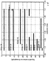
- Fig. 6a shows a graphical representation of an example interference-limited scenario in a cellular network comprising a plurality of eNodeBs, according to one embodiment of the disclosure.
- Fig. 6b shows simulation results of the experienced throughput in the interference-limited scenario depicted in Fig. 6a, according to one embodiment of the disclosure.
- Fig. 6c shows a graphical representation of an improvement in throughput of the interference-limited packet in Fig. 6a, after implementing the load balancing method, according to one embodiment of the disclosure.
- Fig. 6d shows simulation results of the improvement in the experienced throughput in the interference-limited scenario depicted in Fig. 6c, according to one embodiment of the disclosure.
- Fig. 7 shows a method for determining RSRP/RSRQ/RSSI measurements for an antenna port, according to one embodiment of the disclosure.
- Fig. 8 illustrates a flow chart for a method that facilitates load balancing in an Evolved NodeB (eNB) in a cellular network comprising a plurality of eNodeBs, according to various embodiments described herein.
- eNB Evolved NodeB
- Fig. 9 illustrates a flow chart for a method that facilitates load balancing in a user equipment (UE) in a cellular network comprising a plurality of eNodeBs, according to various embodiments described herein.
- UE user equipment
- Fig. 10 illustrates, for example components of a User Equipment (UE) device 1000, according to one embodiment of the disclosure.
- UE User Equipment
- an Evolved NodeB operable to perform load balancing in a cellular network comprised of a plurality of eNodeBs.
- the eNodeB comprises a transmit circuitry configured to transmit a load information and a reference signal (RS) that identifies the eNodeB, to a user equipment (UE) having a reception beam directed to the eNodeB, in a coverage area of the eNodeB.
- RS reference signal
- the eNodeB comprises a receive circuitry configured to receive a plurality of first evaluation metrics from the UE, wherein each of the plurality of first evaluation metrics is determined based on a load information and a reference signal of a respective one of the plurality of eNodeBs.
- the eNodeB comprises a processor circuitry configured to determine a reception beam direction for the UE based on the plurality of first evaluation metrics.
- the transmit circuitry is further configured to transmit a command signal with information on the determined reception beam direction to the UE.
- a computer-readable storage device storing computer-executable instructions that, in response to execution, cause an eNodeB of a cellular network comprising a plurality of eNodeBs to calculate a load information of the eNodeB and transmit the load information to one or more user equipments (UEs) in the coverage area of the eNodeB.
- UEs user equipments
- the computer-executable instructions when executed, configure a UE from the one or more UEs in the coverage area of the eNodeB, having a reception beam directed to the eNodeB, to report an evaluation metric of each of the plurality of eNodeBs in the cellular network to the eNodeB, wherein the evaluation metric is determined at least in part on the load information of the respective eNodeB.
- the computer-executable instructions when executed, determine a reception beam direction for the UE based on the evaluation metric of each of the plurality of eNodeBs, in accordance with a predetermined algorithm.
- a user equipmet comprises a receive circuitry configured to receive a load information and a reference signal (RS) from each of a plurality of eNodeBs. Further, the UE comprises a processing circuitry configured to determine an evaluation metric for each of the plurality of eNodeBs, based on the load information and the reference signal received from each of the plurality of eNodeBs. The UE also comprises a transmit circuitry configured to transmit the determined plurality of evaluation metrics to a select eNodeB of the plurality of eNodeBs, wherein the select eNodeB comprises an eNodeB towards which a reception beam direction of the UE is set. In addition, the UE processing circuitry is further configured to selectively change the reception beam direction of the UE to a neighboring eNodeB, based on a command signal from the select eNodeB.
- RS reference signal
- a computer-readable storage device storing computer-executable instructions that, in response to execution, cause a user equipment (UE) in a cellular network comprising a plurality of eNodeBs to receive a load information and a reference signal (RS) from each of the plurality of eNodeBs and determine a reference signal received power (RSRP) and a received signal strength indicator (RSSI) for each of the plurality of eNodeBs, based on the RS from the respective eNodeB.
- UE user equipment
- RSRP reference signal received power
- RSSI received signal strength indicator
- the computer-executable instructions when executed, cause the UE to determine an evaluation metric for each of the plurality of eNodeBs, based on the load information, RSRP and RSSI for the respective eNodeB and transmit the determined evaluation metrics of each of the plurality of eNodeBs to a select eNodeB of the plurality of eNodeBs, wherein the select eNodeB comprises an eNodeB towards which a reception beam direction of the UE is set.
- a component can be a processor (e.g., a microprocessor, a controller, or other processing device) , a process running on a processor, a controller, an object, an executable, a program, a storage device, a computer, a tablet PC and/or a user equipment (e.g., mobile phone, etc.
- an application running on a server and the server can also be a component.
- One or more components can reside within a process, and a component can be localized on one computer and/or distributed between two or more computers.
- a set of elements or a set of other components can be described herein, in which the term “set” can be interpreted as “one or more. ”
- these components can execute from various computer readable storage media having various data structures stored thereon such as with a module, for example.
- the components can communicate via local and/or remote processes such as in accordance with a signal having one or more data packets (e.g., data from one component interacting with another component in a local system, distributed system, and/or across a network, such as, the Internet, a local area network, a wide area network, or similar network with other systems via the signal) .
- a component can be an apparatus with specific functionality provided by mechanical parts operated by electric or electronic circuitry, in which the electric or electronic circuitry can be operated by a software application or a firmware application executed by one or more processors.
- the one or more processors can be internal or external to the apparatus and can execute at least a part of the software or firmware application.
- a component can be an apparatus that provides specific functionality through electronic components without mechanical parts; the electronic components can include one or more processors therein to execute software and/or firmware that confer (s) , at least in part, the functionality of the electronic components.
- the explosive use of mobile Internet urges the need for even faster cellular systems or the fifth generation (5G) cellular systems.
- the 5G systems are expected to provide much faster user throughput experience.
- high frequency bands e.g. centimeter or millimeter wavelength bands
- the channel characteristics are quite different at high frequency bands (e.g., 30GHz-300GHz) .
- One of the major differenceS is that the signal strength decays much faster in high frequency bands compared to low frequency bands. Together with other factors such as increased additive white noise and phase noise, the overall link budget can be much reduced for high frequency bands.
- the antenna wavelength is much shorter at high frequency bands compared to the low frequency bands.
- UE side beamforming becomes essential to compensate for the link budget loss and ensure sufficient cell coverage with a reasonable infrastructure cost.
- analog beamforming the UE can effectively create a very narrow beam towards one spatial direction. Thus any signals received from that spatial direction are enhanced and the other signals are weakened.
- the user experienced throughput is a measure of data speed in cellular networks or the actual rate at which information is transferred in cellular networks.
- the noise limited scenario the user experienced throughput (usually measured in bits per second) is mainly limited by the available bandwidth.
- the experienced throughput for example, packets per second or bits per second, is heavily impacted by whether a system bandwidth is shared between this packet and other packets via FDM, SDM etc.
- the user experienced throughput can drop when other packets enter a transmitting queue of the same transmission point or eNodeB of the packet.
- a packet usually refers to a unit of data that is routed between an origin and a destination on the Internet or any other packet-switched network.
- the origin can be an eNodeB and the destination can be a user equipment (UE) .
- UE user equipment
- the user experienced throughput is mainly limited by a dominant interference.
- the dominant interference to a packet of data being transmitted by a transmission point may be caused by another packet transmitted by a neighboring transmission point or eNodeB.
- Embodiments described herein address the noise limited scenario and the interference limited scenario in cellular networks, in order to increase the user experienced throughput.
- the objective is to utilize UE beamforming to perform radio resource management (RRM) measurements and utilize the RRM measurements to perform load balancing in 5G cellular networks.
- the load balancing is achieved by changing a transmission point of a UE within the network, based on the RRM measurements.
- radio resource management has long been an important topic in wireless communication, conventional RRM schemes for low frequency bands are designed assuming omni-directional reception at the UE. For UEs with omni-directional reception/transmission, changing a transmission point is accompanied with receiving stronger interference. For 5G cellular systems at high band, UE directional reception/transmission is advantageous to guarantee sufficient signal strength. For UEs with directional reception/transmission, however, changing the transmission point is not always accompanied by receiving stronger interference.
- a cellular network comprises a plurality of transmission points or eNodeBs and a load information comprises a number of active data packets being served by each of these transmission points.
- the RRM measurements include a reference signal received power (RSRP) , a reference signal received quality (RSRQ) and a received signal strength indicator (RSSI) .
- Fig. 1 depicts an example implementation of load balancing in a cellular network 100, assuming directional reception/transmission at a UE within the cellular network, according to one embodiment of the disclosure.
- the cellular network 100 comprises two transmission points, however, in other embodiments, the cellular network 100 can have two or more transmission points or eNodeBs.
- the cellular network 100 comprises a first transmission point TP0 102, a second transmission point TP1 104 and a user equipment (UE) 106.
- UE user equipment
- the first transmission point TP0 102 and the second transmission point TP1 104 are configured to transmit a reference signal and a load information to one or more UEs in the coverage area of the first transmission point TP0 102 and the second transmission point TP1 104, respectively.
- the load information of the first transmission point TP0 102 and the second transmission point TP1 104 comprises the number of active packets currently being served by the first transmission point TP0 102 and the second transmission point TP1 104, respectively.
- the UE 106 is configured to create a narrow reception beam 108 towards the transmission point TP0 102, in order to achieve directional reception at the UE 106.
- the direction of the narrow reception beam 108 can be configured by the network 100 by choosing the TP it is meant for.
- an initial direction of the reception beam 108 is determined by a central network controller (not shown) based on some predetermined conditions, for example, proximity of a TP to a UE.
- the load balancing in the cellular network 100 is performed based on measurement of an evaluation metric for each of the first transmission point TP0 102 and the second transmission point TP1 104 at the UE 106.
- the evaluation metric for the first transmission point TP0 102 and the second transmission point TP1 104 are determined based on the reference signal and the load information of the transmission points TP0 102 and TP1 104, respectively.
- the evaluation metric for the first transmission point TP0 102 is determined at the UE 106 based on a reference signal received power (RSRP) /received signal strength indicator (RSSI) and the load information of TP0.
- RSRP reference signal received power
- RSSI referenced signal strength indicator
- the evaluation metric for the second transmission point TP1 104 is determined at the UE 106 based on RSRP/RSSI and the load information of TP1.
- the RSRP/RSSI for TP0 and TP1 are in turn determined at the UE 106, based on the reference signal received from the transmission points TP0 and TP1, respectively.
- RSRP/RSSI measurements are performed based on a common reference signal (CRS) .
- CRS common reference signal
- the RSRP/RSSI measurements are performed based on a channel state information reference signal (CSI-RS) .
- CSI-RS channel state information reference signal
- the UE 106 in one embodiment creates the narrow reception beam 108 towards TP0.
- the UE 106 creates the narrow reception beam 108 by adjusting an angle associated with an antenna or a plurality of antennas in an antenna array of the UE 106, based on a command signal from an eNodeB or a network controller.
- the narrow reception beam 108 will enhance the signal/interference in the beam direction and mitigate the interference in other directions.
- the RSRP/RSRQ/RSSI for a given TP becomes a function of the one particular reception direction.
- the network 100 can ask UE 106 to report RSRP/RSSI for TP1 when the reception direction is set to TP 0.
- the RSRP/RSSI measurements for the TP1 104 is performed at the UE 106 by temporarily changing the reception beam direction from 108, thereby creating the reception beam 110 to point towards the transmission point TP1 104, as illustrated in Fig. 1.
- the RSRP/RSSI measurements for TP0 102 and TP1 104, determined at the UE 106 along with the load information of TP0 102 and TP1 104, respectively, are utilized for determining the evaluation metrics at the UE 106.
- the load balancing comprises selectively changing the reception beam direction of the UE 106, for example, from the transmission point TP0 102 to the transmission point TP1 104, or vice versa.
- the transmission point or the reception beam direction is selectively changed based on the evaluation metrics of the first transmission point TP0 102 and the second transmission point TP1 104, in accordance with a predetermined algorithm.
- the predetermined algorithm is performed at the transmission points TP0 or TP1. For example, when the reception beam is directed towards the first transmission point TP0 102, the TP0 102 performs the predetermined algorithm on the evaluation metrics, to determine a new reception beam direction.
- the TP0 102 decides to set the reception beam direction of the UE 106 to TP0 102 itself or to TP1 104.
- the evaluation metrics determined at the UE 106 is transmitted to TP0 102 prior to performing the predetermined algorithm, in order to achieve load balancing.
- the evaluation metrics determined at a UE comprises a first evaluation metric T1 (i) and a second evaluation metric T2 (i) for each of the transmission points or eNodeBs of a cellular network.
- the evaluation metrics determined at the UE 106 comprises a first evaluation metric T1 and a second evaluation metric T2 for both TP0 102 and TP1 104, respectively.
- the first evaluation metric T1 (i) for each of the transmission point TP i is determined as below:
- i) is the reference signal received power for the transmission point TP i when the reception beam of a UE points to TP i .
- the second evaluation metric T2 (i) for each of the transmission points TP i is determined as below
- i) is the reference signal received power and RSSI(i) is the received signal strength indicator or the normalized total receiving power per resource element (RE) for a transmission point TP i when the reception beam of a UE points to TP i
- P (i) is the number of packets currently being served by TP i .
- the number of packets P (i) currently being served by a transmission point TP i corresponds to the load information transmitted by the transmission point TP i .
- the load information P (i) is transmitted from a transmission point to a UE by encoding P (i) in TP specific broadcasting channels such as the physical broadcasting channel (PBCH) or the system information blocks (SIBs) .
- the load information P (i) can be transmitted from a transmission point to a UE by encoding P (i) in reference signal sequences.
- the reference signal sequence can have the structure of one pseudo-sequence modulated by one orthogonal cover sequence.
- the load information P (i) is encoded into the orthogonal sequence index.
- Fig. 2 depicts a flowchart 200 for implementing the predetermined algorithm on the evaluation metrics given in equations (1) - (2) at an eNodeB, for enabling load balancing in cellular networks, according to one embodiment of the disclosure.
- the algorithm herein is described with reference to the cellular network 100 of Fig. 1 comprising two transmission points. However, in other embodiments, this algorithm could be applied for other cellular systems comprising two or more transmission points or eNodeBs.
- the predetermined algorithm is implemented within a transmission point to which a UE reception beam is directed.
- the predetermined algorithm can be implemented using a processing circuit within the transmission point TP0 to which the reception beam of the UE 106 is directed.
- a determination whether the second evaluation metric of TP0 is 50%greater than the second evaluation metric of TP1 is performed. If yes, the method proceeds to 404, where TP0 is chosen as the serving TP for the UE 106. If No, the method proceeds to 406. At 406, a determination whether the first evaluation metric of TP0 is greater than the first evaluation metric of TP1 is performed. If yes, the method proceeds to 408, where TP0 is chosen as the serving TP for the UE 106. If No, the method proceeds to 410, where TP1 is chosen as the serving TP for the UE 106.
- a greater value of the second evaluation metric of TP0 with respect to TP1 indicates that the TP0 is more lightly loaded than TP1 or has a better signal strength as compared to TP1.
- a greater value of the first evaluation metric of TP0 with respect to TP1 indicates that TP0 has a better RSRP compared to TP1.
- TP1 is chosen as the serving TP based on the above predetermined algorithm, then the reception beam direction of the UE 106 is changed from TP0 to TP1.
- the second evaluation metric of TP0 is compared with the second evaluation metrics of each of TP1, TP2 ... TPn.
- the first evaluation metric of TP0 is compared with the first evaluation metrics of each of TP1, TP2 ... TPn.
- Fig. 3 illustrates a block diagram of an apparatus 300 for use in an Evolved NodeB (eNB) in a cellular network that facilitates load balancing, according to various embodiments described herein.
- the eNodeB is described herein with reference to the eNodeB or transmission point TP0 102 in the cellular network 100 in Fig. 1 comprising two transmission points or eNodeBs.
- the cellular network can comprise a plurality of eNodeBs or transmission points.
- the apparatus 300 can include a transmitter circuit 310, a receiver circuit 320 and a processing circuit 330.
- the apparatus comprises a memory circuit 340 coupled to the processor 330.
- the memory circuit 340 comprises a computer readable storage device that includes instructions to be executed by the processor 330.
- the memory circuit 340 can be an independent circuit and in other embodiments, the memory circuit 340 can be integrated on chip with the processor 330.
- the instructions to be executed by the processor 330 can be stored on a non-transitory storage medium like CR-ROM, flash drive etc., and can be downloaded to the memory circuit 340 for execution.
- the receiver circuit 320 and the transmitter circuit 310 can have one or more components in common, and both can be included within a transceiver circuit, while in other aspects they are not.
- the apparatus 300 can be included within an Evolved Universal Terrestrial Radio Access Network (E-UTRAN) Node B (Evolved NodeB, eNodeB, or eNB) .
- E-UTRAN Evolved Universal Terrestrial Radio Access Network
- NodeB Evolved NodeB, eNodeB, or eNB
- the transmitter circuit 310 is configured to transmit a load information and a reference signal (RS) that identifies the eNodeB, to one or more user equipments (UEs) in the coverage area of the eNodeB.
- RS reference signal
- a transmitter circuit within the eNodeB 102 is configured to transmit a load information and a reference signal (RS) to the UE 106.
- the transmitter circuit within TP0 102 is further configured to transmit an identifier (ID) that identifies the eNodeB 102 to the UE 106.
- the UE 106 creates a narrow reception beam that point towards TP0 in order to determine an evaluation metric based on the load information and the reference signal transmitted by the TP0 102.
- An initial direction of the reception beam of the UE 106 in some embodiments, is determined by the eNodeBs, for example, eNodeB TP0 102, based on some operating conditions like a proximity of the UE 106 to an eNodeB, however, in other embodiments, the initial direction of the reception beam of the UE 106 is determined by a central network controller (not shown) external to the eNodeB 102.
- the receiver circuit 320 in Fig. 3 is configured to receive a plurality of evaluation metrics from a UE which has a reception beam directed towards the eNodeB and each of the plurality of evaluation metrics corresponds to one of the plurality of eNodeBs in the network.
- a receive circuit within TP0 102 is configured to receive an evaluation metric corresponding to TP0 and an evaluation metric corresponding to TP1 from the UE 102.
- the memory circuit 340 is configured to store the plurality of evaluation metrics received from the UE.
- the transmit circuit 310 is further configured to transmit an evaluation report request to the UE 106 that configures the UE 106 to send the plurality of evaluation matrices to the eNodeB TP0 102.
- the evaluation metric for each TP comprises a first evaluation metric determined based on the RS from the respective TP and a second evaluation metric determined based on both the RS and the load information from the respective TP.
- the processing circuit 330 is operably coupled to the receiver circuit 320 and the memory circuit 340, and is configured to determine a reception beam direction for the UE based on the plurality of evaluation metrics, in accordance with a predetermined algorithm.
- the eNodeB TP0 102 is configured to determine a reception beam direction for the UE 106 based on the plurality of evaluation metrics received from the UE 106.
- the determined reception beam direction of the UE 106 comprises a reception beam directed to the eNodeB TP0 102 itself or to the neighboring eNodeB TP1 104.
- the predetermined algorithm is implemented in accordance with the algorithm depicted in Fig. 2.
- the transmitter circuit 310 for example of TP0 in Fig. 1, is further configured to transmit a command signal with information on the determined reception beam direction to the UE 106 in order to selectively change the reception beam direction of the UE 106.
- the transmitter circuit 310 is further configured to transmit a temporary command signal to temporarily change the reception beam direction of the UE 106 to one or more neighboring eNodeBs (e.g., TP1 in Fig. 1) , prior to receiving the plurality of evaluation metrics from the UE 106.
- Temporarily changing the reception beam direction of the UE enables the UE to determine the evaluation metrics of each of the plurality of eNodeBs in the network.
- Fig. 4 illustrates a block diagram of an apparatus 400 for use in a user equipment (UE) in a cellular network that facilitates load balancing, according to various embodiments described herein.
- the UE is described herein with reference to the UE 106 in the cellular network 100 in Fig. 1 comprising two transmission points or eNodeBs.
- the cellular network can comprise two or more eNodeBs or transmission points.
- the apparatus 400 includes a receiver circuit 410, a processing circuit 430, and a transmitter circuit 420. Further, in some embodiments, the apparatus 400 comprises a memory circuit 440 coupled to the processing circuit 430.
- the memory circuit 440 comprises a computer readable storage device that includes instructions to be executed by the processor 430.
- the memory circuit 440 can be an independent circuit and in other embodiments, the memory circuit 440 can be integrated on chip with the processor 430.
- the instructions to be executed by the processor 430 can be stored on a non-transitory storage medium like CR-ROM, flash drive etc., and can be downloaded to the memory circuit 440 for execution.
- Each of the receiver circuit 410 and the transmitter circuit 420 are configured to be coupled to one or more antennas, which can be the same or different antenna (s) .
- the receiver circuit 410 and transmitter circuit 420 can have one or more components in common, and both can be included within a transceiver circuit, while in other aspects they are not.
- the apparatus 400 can be included within a UE, for example, with apparatus 400 (or portions thereof) within a receiver and transmitter or a transceiver circuit of a UE.
- the receiver circuit 410 is configured to receive a load information and a reference signal (RS) from a plurality of eNodeBs in the cellular network.
- a receiver circuit within the UE 106 is configured to receive a load information and a reference signal from both TP0 102 and TP1 104.
- the load information of an eNodeB comprises the number of active packets in the sending queue of the respective transmission point or eNodeB.
- the UE creates a narrow reception beam that points toward a select eNodeB of the plurality of eNodeBs in the cellular network in order to facilitate sufficient signal strength during transmission/reception.
- An initial direction of the reception beam of the UE in some embodiments, is determined by the eNodeBs, based on some operating conditions like a proximity of the UE to an eNodeB, however, in other embodiments, the initial direction of the reception beam of the UE is determined by a central network controller (not shown) external to the eNodeBs.
- the UE 106 In the cellular network 100 of Fig. 1, the UE 106 is configured to create an initial reception beam towards TP0 102.
- the processing circuit 430 is operably coupled to the receiver circuit 410 and is configured to determine an evaluation metric for each of the plurality of eNodeBs in the network, based on the load information and the reference signal received from the respective eNodeB. For example, in the cellular network 100 of Fig. 1, the processing circuit 430 is configured to determine an evaluation metric for the eNodeBs TP0 102 and TP1 104, respectively. In some embodiments, the processing circuit 430 is configured to temporarily change the reception beam direction of the UE to each of the plurality of eNodeBs in the cellular network, in order to determine the evaluation metric associated with the respective eNodeB. For example, in the cellular network 100 of Fig.
- the reception beam direction 108 of the UE 106 is temporarily changed to point towards TP1 104, thereby forming the reception beam 110 in order to determine the evaluation metric of TP1 104.
- the receiver circuit 410 is further configured to receive a temporary command signal from the eNodeB towards which the reception beam of the UE is set, based on which the reception beam direction of the UE is temporarily changed.
- the memory circuit 440 is coupled to the processing circuit 430 and is configured to store the evaluation metric for each of the plurality of eNodeBs in the network.
- the transmitter circuit 420 is configured to transmit the determined plurality of evaluation metrics to a select eNodeB of the plurality of eNodeBs, wherein the select eNodeB comprises an eNodeB towards which a reception beam direction of the UE is set.
- a transmitter circuit within the UE 106 is configured to transmit the evaluation metrics of TP0 102 and TP1 104, respectively to TP0 102.
- the plurality of evaluation metrics is transmitted to the select eNodeB, based on an evaluation report request received from the select eNodeB.
- the receiver circuit 410 is configured to receive the evaluation report request from the select eNodeB.
- the receiver circuit 410 is configured to receive a command signal containing information on a reception beam direction of the UE from the select eNodeB.
- the reception beam direction is the same as the initial reception beam direction of the UE, however, in other embodiments, the reception beam direction is different from the initial reception beam direction.
- the reception beam direction is determined at the select eNodeB based on the plurality of evaluation metrics in accordance with a predetermined algorithm similar to the algorithm depicted in Fig. 2.
- the processing circuit 430 is configured to selectively change the reception beam direction of the UE to a neighboring eNodeB. Selectively changing the reception beam direction of the UE comprises adjusting an angle associated with an antenna or a plurality of antennas in an antenna array of the UE, based on the command signal from the select eNodeB.
- Fig. 5a shows a graphical representation of an example noise-limited scenario 500 in a cellular network comprising a plurality of eNodeBs and Fig. 5b shows simulation results of the experienced throughput in the noise-limited scenario depicted in Fig. 5a.
- 502 represents a “signal of interest” or a “packet of interest” (represented by MSID 61 as seen in Fig. 5b) being transmitted by an eNodeB, for example, BSIdx: 16.
- 504 in Fig. 5a represent white noise power and all the other lines represent interferences from other transmission points or eNodeBs.
- the experienced throughput for this packet of interest is heavily impacted when the bandwidth of the eNodeB transmitting the “packet of interest” is shared between this packet and other packets via FDM/SDM.
- a second packet enters the transmitting queue of the eNodeB BSIdx: 16, during the life cycle of the packet of interest, for example at 1.32 seconds.
- plot 510 it can be seen that the user experienced throughput of the packet of interest (MSID 61) drops after 1.32 seconds.
- PRBs physical resource blocks
- Fig. 5c shows a graphical representation of an improvement in throughput of the noise-limited packet, MSID 61 in Fig. 5a above, after implementing the load balancing method discussed above. Since the eNodeB, BSIdx 16 is heavily loaded, the throughput of the noise-limited packet, MSID 16 can be improved by implementing the load balancing method. After implementing the load balancing method, the second packet, in some embodiments, is offloaded to a different transmission point or eNodeB within the cellular network. As a result, the packet of interest, that is, MSID 61 does not need to share its bandwidth with other packets. Therefore, as can be seen from the plot 540 in Fig.
- the entire bandwidth or physical resource blocks (PRBs) is allocated to the packet of interest, MSID 61 during its life cycle (say, up to 1.38 seconds) . Further, from plot 530 in Fig. 5d, it can be seen that there is no throughput drop after 1.32 seconds, compared to the plot 510 in Fig. 5b. In some embodiments, the experienced throughput is improved by over eighty percent.
- PRBs physical resource blocks
- Fig. 6a shows a graphical representation of an example interference-limited scenario 600 in a cellular network comprising a plurality of eNodeBs and Fig. 6b shows simulation results of the experienced throughput in the interference-limited scenario depicted in Fig. 6a.
- 602 represents a “signal of interest” or a “packet of interest” (represented by MSID 53 as seen in Fig. 6b) being transmitted by an eNodeB, for example, BSIdx: 0.
- 604 in Fig. 6a represent a dominant interferer, for example, a signal from a neighboring transmission point or eNodeB BSIdx: 1 and 606 represents white noise power.
- All the other lines represent interferences from other transmission points or eNodeBs, weaker than the white noise. Due to the dominant interferer 604, the experienced throughput of the packet of interest is reduced, while the dominant interferer is transmitting data. From Fig. 6b, plot 610, it can be seen that the experienced throughput of the packet of interest is improved when the dominant interferer 604 finishes it transmission at around 2.26 seconds.
- Fig. 6c shows a graphical representation of an improvement in throughput of the interference-limited packet, MSID 53 in Fig. 6a above, after implementing the load balancing method discussed above. Since the eNodeB BSIdx: 0 receives dominant interference from the eNodeB BSIdx: 1, the load balancing algorithm selects eNodeB BSIdx: 8 as the serving eNodeB, instead of the eNodeB BSIdx: 0.
- the effective decoding signal-to-interference and noise ratio is much improved because the dominant interference from the eNodeB BSIdx: 1 is mitigated.
- the experienced throughput is improved by over 80%as can be seen in the plot 660 of Fig. 6d.
- Fig. 7 shows a method for determining RSRP/RSRQ/RSSI measurements for an antenna port, according to one embodiment of the disclosure.
- Fig. 7 illustrates an example time-frequency chart of a subframe 700 indicating possible resource elements (REs) used for transmitting a common reference signal (CRS) for an antenna port 0.
- the RSRP/RSRQ/RSSI measurements are performed based on CRS, however, in other embodiments, the RSRP/RSRQ/RSSI measurements are performed based on a channel state information reference signal (CSI-RS) .
- CSI-RS channel state information reference signal
- the subframe 700 comprises a plurality of REs, for example, 702 configured to transmit the CRS for a plurality of antenna ports and a plurality of orthogonal frequency division multiplexing (OFDM) symbols, for example 708.
- the subframe 700 comprises 2 slots 710 and 712, each comprising 6 OFDM symbols, for example 708.
- the RSRP for the antenna port 0 is measured over all the REs that contain the CRS for the antenna port 0, for example R0 704 and all the other REs marked as R0 within the subframe 700 in Fig. 7.
- the RSSI for the antenna port 0 is measured over the four OFDM symbols that carry the CRS for the antenna port 0, for example, the OFDM symbol 706 and three other OFDM symbols depicted in a darker shade in the subframe 700 Fig. 7.
- the RSRQ for the antenna port 0 is derived from the RSRP and RSSI of the antenna port 0, based on the equation:
- N is the number of PRBs to make the RSSI measurement.
- the antenna port and an eNodeB are the same. Additional details regarding CRS and CSI-RS based RSRP/RSRQ/RSSI measurements are provided in the physical layer measurement specification 3GPP TS36.214 vc. 1.0.
- Fig. 8 shows a flow chart for a method 800 that facilitates load balancing in an Evolved NodeB (eNB) in a cellular network comprising a plurality of eNodeBs, according to various embodiments described herein.
- the method 800 is described herein with reference to the apparatus 300 in Fig. 3.
- a load information and a reference signal (RS) that identifies the eNodeB is transmitted from the transmitter circuit 310 to a user equipment (UE) having a reception beam of the UE directed to the eNodeB, in a coverage area of the eNodeB.
- UE user equipment
- a plurality of evaluation metrics is received from the UE at the receiver circuit 320, wherein each of the plurality of evaluation metrics is determined at the UE based on a load information and a reference signal of one of the plurality of eNodeBs, respectively.
- a reception beam direction for the UE is determined at the processing circuit 330 of the eNodeB based on the plurality of evaluation metrics, in accordance with a predetermined algorithm.
- a command signal with information on the determined reception beam direction is transmitted from the transmitter circuit 310 of the eNodeB to the UE.
- Fig. 9 illustrates a flow chart for a method 900 that facilitates load balancing in a user equipment (UE) in a cellular network comprising a plurality of eNodeBs, according to various embodiments described herein.
- the method 600 is described herein with reference to the apparatus 400 in Fig. 4.
- a load information and a reference signal (RS) from a plurality of eNodeBs is received at the receiver circuit 410.
- an evaluation metric for each of the plurality of eNodeBs is determined at the processing circuit 430, based on the load information and the reference signal received from each of the plurality of eNodeBs.
- RS reference signal
- the determined plurality of evaluation metrics is transmitted from the transmitter circuit 420 to a select eNodeB of the plurality of eNodeBs, wherein the select eNodeB comprises an eNodeB towards which a reception beam direction of the UE is set.
- a reception beam direction of the UE is selectively changed from the select eNodeB to a neighboring eNodeB at the processing unit 430, based on a command signal from the select eNodeB.
- Fig. 10 illustrates, for one embodiment, example components of a User Equipment (UE) device 1000.
- the UE device 1000 may include application circuitry 1002, baseband circuitry 1004, Radio Frequency (RF) circuitry 1006, front-end module (FEM) circuitry 1008 and one or more antennas 1010, coupled together at least as shown.
- RF Radio Frequency
- FEM front-end module
- the application circuitry 1002 may include one or more application processors.
- the application circuitry 1002 may include circuitry such as, but not limited to, one or more single-core or multi-core processors.
- the processor (s) may include any combination of general-purpose processors and dedicated processors (e.g., graphics processors, application processors, etc. ) .
- the processors may be coupled with and/or may include memory/storage and may be configured to execute instructions stored in the memory/storage to enable various applications and/or operating systems to run on the system.
- the baseband circuitry 1004 may include circuitry such as, but not limited to, one or more single-core or multi-core processors.
- the baseband circuitry 1004 may include one or more baseband processors and/or control logic to process baseband signals received from a receive signal path of the RF circuitry 1006 and to generate baseband signals for a transmit signal path of the RF circuitry 1006.
- Baseband processing circuity 1004 may interface with the application circuitry 1002 for generation and processing of the baseband signals and for controlling operations of the RF circuitry 1006.
- the baseband circuitry 1004 may include a second generation (2G) baseband processor 1004a, third generation (3G) baseband processor 1004b, fourth generation (4G) baseband processor 1004c, and/or other baseband processor (s) 1004d for other existing generations, generations in development or to be developed in the future (e.g., fifth generation (5G) , 6G, etc. ) .
- the baseband circuitry 1004 e.g., one or more of baseband processors 1004a-d
- the radio control functions may include, but are not limited to, signal modulation/demodulation, encoding/decoding, radio frequency shifting, etc.
- modulation/demodulation circuitry of the baseband circuitry 1004 may include Fast-Fourier Transform (FFT) , precoding, and/or constellation mapping/demapping functionality.
- FFT Fast-Fourier Transform
- encoding/decoding circuitry of the baseband circuitry 1004 may include convolution, tail-biting convolution, turbo, Viterbi, and/or Low Density Parity Check (LDPC) encoder/decoder functionality.
- LDPC Low Density Parity Check
- the baseband circuitry 1004 may include elements of a protocol stack such as, for example, elements of an evolved universal terrestrial radio access network (EUTRAN) protocol including, for example, physical (PHY) , media access control (MAC) , radio link control (RLC) , packet data convergence protocol (PDCP) , and/or radio resource control (RRC) elements.
- EUTRAN evolved universal terrestrial radio access network
- a central processing unit (CPU) 1004e of the baseband circuitry 1004 may be configured to run elements of the protocol stack for signaling of the PHY, MAC, RLC, PDCP and/or RRC layers.
- the baseband circuitry may include one or more audio digital signal processor (s) (DSP) 1004f.
- DSP audio digital signal processor
- the audio DSP (s) 1004f may be include elements for compression/decompression and echo cancellation and may include other suitable processing elements in other embodiments.
- Components of the baseband circuitry may be suitably combined in a single chip, a single chipset, or disposed on a same circuit board in some embodiments.
- some or all of the constituent components of the baseband circuitry 1004 and the application circuitry 1002 may be implemented together such as, for example, on a system on a chip (SOC) .
- SOC system on a chip
- the baseband circuitry 1004 may provide for communication compatible with one or more radio technologies.
- the baseband circuitry 1004 may support communication with an evolved universal terrestrial radio access network (EUTRAN) and/or other wireless metropolitan area networks (WMAN) , a wireless local area network (WLAN) , a wireless personal area network (WPAN) .
- EUTRAN evolved universal terrestrial radio access network
- WMAN wireless metropolitan area networks
- WLAN wireless local area network
- WPAN wireless personal area network
- multi-mode baseband circuitry Embodiments in which the baseband circuitry 1004 is configured to support radio communications of more than one wireless protocol.
- RF circuitry 1006 may enable communication with wireless networks using modulated electromagnetic radiation through a non-solid medium.
- the RF circuitry 1006 may include switches, filters, amplifiers, etc. to facilitate the communication with the wireless network.
- RF circuitry 1006 may include a receive signal path which may include circuitry to down-convert RF signals received from the FEM circuitry 1008 and provide baseband signals to the baseband circuitry 1004.
- RF circuitry 1006 may also include a transmit signal path which may include circuitry to up-convert baseband signals provided by the baseband circuitry 1004 and provide RF output signals to the FEM circuitry 1008 for transmission.
- the RF circuitry 1006 may include a receive signal path and a transmit signal path.
- the receive signal path of the RF circuitry 1006 may include mixer circuitry 1006a, amplifier circuitry 1006b and filter circuitry 1006c.
- the transmit signal path of the RF circuitry 1006 may include filter circuitry 1006c and mixer circuitry 1006a.
- RF circuitry 1006 may also include synthesizer circuitry 1006d for synthesizing a frequency for use by the mixer circuitry 1006a of the receive signal path and the transmit signal path.
- the mixer circuitry 1006a of the receive signal path may be configured to down-convert RF signals received from the FEM circuitry 1008 based on the synthesized frequency provided by synthesizer circuitry 1006d.
- the amplifier circuitry 1006b may be configured to amplify the down-converted signals and the filter circuitry 1006c may be a low-pass filter (LPF) or band-pass filter (BPF) configured to remove unwanted signals from the down-converted signals to generate output baseband signals.
- LPF low-pass filter
- BPF band-pass filter
- Output baseband signals may be provided to the baseband circuitry 1004 for further processing.
- the output baseband signals may be zero-frequency baseband signals, although this is not a requirement.
- mixer circuitry 1006a of the receive signal path may comprise passive mixers, although the scope of the embodiments is not limited in this respect.
- the mixer circuitry 1006a of the transmit signal path may be configured to up-convert input baseband signals based on the synthesized frequency provided by the synthesizer circuitry 1006d to generate RF output signals for the FEM circuitry 1008.
- the baseband signals may be provided by the baseband circuitry 1004 and may be filtered by filter circuitry 1006c.
- the filter circuitry 1006c may include a low-pass filter (LPF) , although the scope of the embodiments is not limited in this respect.
- LPF low-pass filter
- the mixer circuitry 1006a of the receive signal path and the mixer circuitry 1006a of the transmit signal path may include two or more mixers and may be arranged for quadrature downconversion and/or upconversion respectively.
- the mixer circuitry 1006a of the receive signal path and the mixer circuitry 1006a of the transmit signal path may include two or more mixers and may be arranged for image rejection (e.g., Hartley image rejection) .
- the mixer circuitry 1006a of the receive signal path and the mixer circuitry 1006a may be arranged for direct downconversion and/or direct upconversion, respectively.
- the mixer circuitry 1006a of the receive signal path and the mixer circuitry 1006a of the transmit signal path may be configured for super-heterodyne operation.
- the output baseband signals and the input baseband signals may be analog baseband signals, although the scope of the embodiments is not limited in this respect.
- the output baseband signals and the input baseband signals may be digital baseband signals.
- the RF circuitry 1006 may include analog-to-digital converter (ADC) and digital-to-analog converter (DAC) circuitry and the baseband circuitry 1004 may include a digital baseband interface to communicate with the RF circuitry 1006.
- ADC analog-to-digital converter
- DAC digital-to-analog converter
- a separate radio IC circuitry may be provided for processing signals for each spectrum, although the scope of the embodiments is not limited in this respect.
- the synthesizer circuitry 1006d may be a fractional-N synthesizer or a fractional N/N+1 synthesizer, although the scope of the embodiments is not limited in this respect as other types of frequency synthesizers may be suitable.
- synthesizer circuitry 1006d may be a delta-sigma synthesizer, a frequency multiplier, or a synthesizer comprising a phase-locked loop with a frequency divider.
- the synthesizer circuitry 1006d may be configured to synthesize an output frequency for use by the mixer circuitry 1006a of the RF circuitry 1006 based on a frequency input and a divider control input. In some embodiments, the synthesizer circuitry 1006d may be a fractional N/N+1 synthesizer.
- frequency input may be provided by a voltage controlled oscillator (VCO) , although that is not a requirement.
- VCO voltage controlled oscillator
- Divider control input may be provided by either the baseband circuitry 1004 or the applications processor 1002 depending on the desired output frequency.
- a divider control input (e.g., N) may be determined from a look-up table based on a channel indicated by the applications processor 1002.
- Synthesizer circuitry 1006d of the RF circuitry 1006 may include a divider, a delay-locked loop (DLL) , a multiplexer and a phase accumulator.
- the divider may be a dual modulus divider (DMD) and the phase accumulator may be a digital phase accumulator (DPA) .
- the DMD may be configured to divide the input signal by either N or N+1 (e.g., based on a carry out) to provide a fractional division ratio.
- the DLL may include a set of cascaded, tunable, delay elements, a phase detector, a charge pump and a D-type flip-flop.
- the delay elements may be configured to break a VCO period up into Nd equal packets of phase, where Nd is the number of delay elements in the delay line.
- Nd is the number of delay elements in the delay line.
- synthesizer circuitry 1006d may be configured to generate a carrier frequency as the output frequency, while in other embodiments, the output frequency may be a multiple of the carrier frequency (e.g., twice the carrier frequency, four times the carrier frequency) and used in conjunction with quadrature generator and divider circuitry to generate multiple signals at the carrier frequency with multiple different phases with respect to each other.
- the output frequency may be a LO frequency (fLO) .
- the RF circuitry 1006 may include an IQ/polar converter.
- FEM circuitry 1008 may include a receive signal path which may include circuitry configured to operate on RF signals received from one or more antennas 1010, amplify the received signals and provide the amplified versions of the received signals to the RF circuitry 1006 for further processing.
- FEM circuitry 1008 may also include a transmit signal path which may include circuitry configured to amplify signals for transmission provided by the RF circuitry 1006 for transmission by one or more of the one or more antennas 1010.
- the FEM circuitry 1008 may include a TX/RX switch to switch between transmit mode and receive mode operation.
- the FEM circuitry may include a receive signal path and a transmit signal path.
- the receive signal path of the FEM circuitry may include a low-noise amplifier (LNA) to amplify received RF signals and provide the amplified received RF signals as an output (e.g., to the RF circuitry 1006) .
- the transmit signal path of the FEM circuitry 1008 may include a power amplifier (PA) to amplify input RF signals (e.g., provided by RF circuitry 1006) , and one or more filters to generate RF signals for subsequent transmission (e.g., by one or more of the one or more antennas 1010.
- PA power amplifier
- the UE device 1000 may include additional elements such as, for example, memory/storage, display, camera, sensor, and/or input/output (I/O) interface.
- additional elements such as, for example, memory/storage, display, camera, sensor, and/or input/output (I/O) interface.
- Examples can include subject matter such as a method, means for performing acts or blocks of the method, at least one machine-readable medium including instructions that, when performed by a machine cause the machine to perform acts of the method or of an apparatus or system for concurrent communication using multiple communication technologies according to embodiments and examples described herein.
- Example 1 is an Evolved NodeB (eNodeB) operable to perform load balancing in a cellular network comprised of a plurality of eNodeBs, comprising a transmit circuitry configured to transmit a load information and a reference signal (RS) that identifies the eNodeB, to a user equipment (UE) having a reception beam directed to the eNodeB, in a coverage area of the eNodeB; a receive circuitry configured to receive a plurality of evaluation metrics from the UE, wherein each of the plurality of evaluation metrics is determined at the UE based on a load information and a reference signal of a respective one of the plurality of eNodeBs; and a processor circuitry configured to determine a reception beam direction for the UE based on the plurality of evaluation metrics, wherein the transmit circuitry is further configured to transmit a command signal with information on the determined reception beam direction to the UE.
- RS reference signal
- Example 2 is an eNodeB including the subject matter of example 1, wherein the transmit circuitry is further configured to transmit the load information and the RS to one or more neighboring UEs in the coverage area of the eNodeB.
- Example 3 is an eNodeB including the subject matter of examples 1-2, including or omitting elements, wherein the transmit circuitry is further configured to transmit a temporary command signal to temporarily change the reception beam direction of the UE to one or more neighboring eNodeBs, prior to receiving the plurality of evaluation metrics from the UE.
- Example 4 is an eNodeB including the subject matter of examples 1-3, including or omitting elements, wherein the transmit circuity is further configured to transmit an evaluation report request to the UE that configures the UE to send the plurality of evaluation matrices to the eNodeB.
- Example 5 is an eNodeB including the subject matter of examples 1-4, including or omitting elements, wherein the load information comprises a number of active packets in a sending queue of the eNodeB.
- Example 6 is an eNodeB including the subject matter of examples 1-5, including or omitting elements, wherein the load information is transmitted using a physical broadcast channel (PBCH) of the eNodeB.
- PBCH physical broadcast channel
- Example 7 is an eNodeB including the subject matter of examples 1-6, including or omitting elements, wherein the load information is transmitted using system information blocks (SIBs) of the eNodeB.
- SIBs system information blocks
- Example 8 is an eNodeB including the subject matter of examples 1-7, including or omitting elements, wherein the load information is transmitted by encoding the load information on the reference signal sequences of the eNodeB.
- Example 9 is an eNodeB including the subject matter of examples 1-8, including or omitting elements, the transmit circuitry is further configured to transmit an identifier (ID) that identifies the eNodeB to the UE.
- ID identifier
- Example 10 is an eNodeB including the subject matter of examples 1-9, including or omitting elements, wherein each of the plurality of evaluation metrics received from the UE comprises a first evaluation metric determined based on the reference signal of the respective eNodeB and a second evaluation metric determined based on both the reference signal and the load information of the respective eNodeb.
- Example 11 is an eNodeB including the subject matter of examples 1-10, including or omitting elements, wherein the processor circuitry is configured to determine the reception beam direction of the UE based on the first evaluation metric and the second evaluation metric of each of the plurality of eNodeBs, using a predetermined algorithm.
- Example 12 is an eNodeB including the subject matter of examples 1-11, including or omitting elements, wherein the determined reception beam direction of the UE comprises a reception beam directed to the eNodeB itself or to a neighboring eNodeB.
- Example 13 is a computer-readable storage device storing computer-executable instructions that, in response to execution, cause an eNodeB of a cellular network comprising a plurality of eNodeBs to calculate a load information of the eNodeB; transmit the load information to one or more user equipments (UEs) in the coverage area of the eNodeB; configure a UE from the one or more UEs in the coverage area of the eNodeB, having a reception beam directed to the eNodeB, to report an evaluation metric of each of the plurality of eNodeBs in the cellular network to the eNodeB, wherein the evaluation metric is determined at least in part on the load information of the respective eNodeB; and determine a reception beam direction for the UE based on the evaluation metric of each of the plurality of eNodeBs, in accordance with a predetermined algorithm.
- UEs user equipments
- Example 14 is a computer-readable storage device including the subject matter of example 13, wherein the evaluation metric is determined further based on a reference signal received power (RSRP) or a received signal strength indicator (RSSI) or both of the respective eNodeB.
- RSRP reference signal received power
- RSSI received signal strength indicator
- Example 15 is a computer-readable storage device including the subject matter of examples 13-14, including or omitting elements, wherein the load information comprises a number of active packets in a sending queue of the eNodeB.
- Example 16 is a user equipmet (UE) in a cellular network, comprising a receive circuitry configured to receive a load information and a reference signal (RS) from a plurality of eNodeBs; a processing circuitry configured to determine an evaluation metric for each of the plurality of eNodeBs, based on the load information and the reference signal received from each of the plurality of eNodeBs; and a transmit circuitry configured to transmit the determined plurality of evaluation metrics to a select eNodeB of the plurality of eNodeBs, wherein the select eNodeB comprises an eNodeB towards which a reception beam direction of the UE is set; wherein the processing circuitry is further configured to selectively change the reception beam direction of the UE to a neighboring eNodeB, based on a command signal from the select eNodeB.
- RS reference signal
- Example 17 is a UE including the subject matter of example 16, wherein the command signal is received from the select eNodeB after transmitting the determined plurality of evaluation metrics to the select eNodeB and wherein the command signal comprises information on the reception beam direction determined based on the plurality of evaluation metrics at the select eNodeB.
- Example 18 is a UE including the subject matter of examples 16-17, including or omitting elements, wherein the processing circuitry is further configured to temporarily change the reception beam direction of the UE to one or more neighboring eNodeBs of the select eNodeB, based on a temporary command signal from the select eNodeB, prior to determining the evaluation metric of the respective neighboring eNodeBs.
- Example 19 is a UE including the subject matter of examples 16-18, including or omitting elements, wherein the receive circuitry is further configured to receive both the command signal and the temporary command signal from the select eNodeB.
- Example 20 is a UE including the subject matter of examples 16-19, including or omitting elements, wherein the evaluation metric comprises a first evaluation metric for each of the plurality of eNodeBs determined based on the load information and the reference signal received from each of the plurality of eNodeBs, and a second evaluation metric for each of the plurality of eNodeBs determined based the reference signal received from each of the plurality of eNodeBs.
- Example 21 is a UE including the subject matter of examples 16-20, including or omitting elements, wherein the transmit circuitry is configured to transmit the determined plurality of evaluation metrics to the select eNodeB, in response to an evaluation report request from the select eNodeB.
- Example 22 computer-readable storage device storing computer-executable instructions that, in response to execution, cause a user equipment (UE) in a cellular network comprising a plurality of eNodeBs to receive a load information and a reference signal (RS) from the plurality of eNodeBs; determine a reference signal received power (RSRP) and a received signal strength indicator (RSSI) for each of the plurality of eNodeBs, based on the RS from the respective eNodeB; determine an evaluation metric for each of the plurality of eNodeBs, based on the load information, RSRP and RSSI for the respective eNodeB; and transmit the determined evaluation metrics of each of the plurality of eNodeBs to a select eNodeB of the plurality of eNodeBs, wherein the select eNodeB comprises an eNodeB towards which a reception beam direction of the UE is set.
- RSRP reference signal received power
- RSSI received signal strength
- Example 23 is a computer-readable storage device including the subject matter of example 22, further cause the UE to selectively change the reception beam direction of the UE to a neighboring eNodeB, based on a command signal from the select eNodeB.
- Example 24 is a method for an eNodeB of a cellular network comprising a plurality of eNodeBs, comprising calculating a load information of the eNodeB; transmitting the load information to one or more user equipments (UEs) in the coverage area of the eNodeB; configuring a UE from the one or more UEs in the coverage area of the eNodeB, having a reception beam directed to the eNodeB, to report an evaluation metric of each of the plurality of eNodeBs in the cellular network to the eNodeB, wherein the evaluation metric is determined at least in part on the load information of the respective eNodeB; and determinining a reception beam direction for the UE based on the evaluation metric of each of the plurality of eNodeBs, in accordance with a predetermined algorithm.
- UEs user equipments
- Example 25 is a computer-readable storage device storing computer-executable instructions that, in response to execution, cause an eNodeB of a cellular network comprising a plurality of eNodeBs to perform the method of example 24.
- Example 26 is a method for a user equipment (UE) in a cellular network comprising a plurality of eNodeBs, comprising receiving a load information and a reference signal (RS) from the plurality of eNodeBs; determining a reference signal received power (RSRP) and a received signal strength indicator (RSSI) for each of the plurality of eNodeBs, based on the RS from the respective eNodeB; determining an evaluation metric for each of the plurality of eNodeBs, based on the load information, RSRP and RSSI for the respective eNodeB; and transmitting the determined evaluation metrics of each of the plurality of eNodeBs to a select eNodeB of the plurality of eNodeBs, wherein the select eNodeB comprises an eNodeB towards which a reception beam direction of the UE is set.
- RS reference signal
- RSSI received signal strength indicator
- Example 27 is a computer-readable storage device storing computer-executable instructions that, in response to execution, cause a UE of a cellular network comprising a plurality of eNodeBs to perform the method of example 26.
- DSP digital signal processor
- ASIC application specific integrated circuit
- FPGA field programmable gate array
- a general-purpose processor can be a microprocessor, but, in the alternative, processor can be any conventional processor, controller, microcontroller, or state machine.
Landscapes
- Engineering & Computer Science (AREA)
- Computer Networks & Wireless Communication (AREA)
- Signal Processing (AREA)
- Mobile Radio Communication Systems (AREA)
Abstract
An Evolved NodeB (eNodeB) operable to perform load balancing in a cellular network comprised of a plurality of eNodeBs, comprises a transmit circuitry configured to transmit a load information and a reference signal that identifies the eNodeB, to a user equipment (UE) having a reception beam directed to the eNodeB, in a coverage area of the eNodeB. Further, the eNodeB comprises a receive circuitry configured to receive a plurality of evaluation metrics from the UE, wherein each of the plurality of evaluation metrics is determined based on a load information and a reference signal of a respective one of the plurality of eNodeBs. Furthermore, the eNodeB comprises a processor circuitry configured to determine a reception beam direction for the UE based on the plurality of evaluation metrics. In addition, the transmit circuitry is configured to transmit a command signal with information on the determined reception beam direction to the UE.
Description
The present disclosure relates to cellular systems and, in particular, to a method, an apparatus and a computer program for load balancing in cellular systems.
While the fourth generation cellular systems (3GPP LTE) are being deployed worldwide, the explosive usage of mobile Internet urges even faster cellular systems, or the fifth generation (5G) cellular systems. Further, a global bandwidth shortage facing wireless carriers has motivated the consideration of the underutilized millimeter wave (mm Wave) frequency spectrum for future broadband cellular communication networks. mm Wave (or extremely high frequency) generally refer to the frequency range between 30 and 300 gigahertz (GHz) . This is the highest radio frequency band in practical use today. Radio waves in this band have wavelengths from ten to one millimeter, giving it the name millimeter band or millimeter wave.
The amount of wireless data might increase one thousand fold over the next ten years. Essential elements in solving this challenge include obtaining more spectrum, having smaller cell sizes, and using improved technologies enabling more bits/s/Hz. An important element in obtaining more spectrum is to move to higher frequencies, above 6 GHz. For the fifth generation wireless systems (5G) , however, the user experienced throughput is limited by available bandwidth (noise limited scenario) and dominant interference (interference limited scenario) .
Some examples of circuits, apparatuses and/or methods will be described in the following by way of example only. In this context, reference will be made to the accompanying Figures.
Fig. 1 depicts an example implementation of load balancing in a cellular network, assuming directional reception/transmission at a UE within the cellular network, according to one embodiment of the disclosure.
Fig. 2 depicts a flowchart for implementing the predetermined algorithm on the evaluation metrics at an eNodeB, for enabling load balancing in cellular networks, according to one embodiment of the disclosure.
Fig. 3 illustrates a block diagram of an apparatus for use in an Evolved NodeB (eNB) in a cellular network that facilitates load balancing, according to various embodiments described herein.
Fig. 4 illustrates a block diagram of an apparatus for use in a user equipment (UE) in a cellular network that facilitates load balancing, according to various embodiments described herein.
Fig. 5a shows a graphical representation of an example noise-limited scenario in a cellular network comprising a plurality of eNodeBs, according to one embodiment of the disclosure.
Fig. 5b shows simulation results of the experienced throughput in the noise-limited scenario depicted in Fig. 5a, according to one embodiment of the disclosure.
Fig. 5c shows a graphical representation of an improvement in throughput of the noise-limited packet in Fig. 5a, after implementing the load balancing method, according to one embodiment of the disclosure.
Fig. 5d shows simulation results of the improvement in the experienced throughput in the noise-limited scenario depicted in Fig. 5c, according to one embodiment of the disclosure.
Fig. 6a shows a graphical representation of an example interference-limited scenario in a cellular network comprising a plurality of eNodeBs, according to one embodiment of the disclosure.
Fig. 6b shows simulation results of the experienced throughput in the interference-limited scenario depicted in Fig. 6a, according to one embodiment of the disclosure.
Fig. 6c shows a graphical representation of an improvement in throughput of the interference-limited packet in Fig. 6a, after implementing the load balancing method, according to one embodiment of the disclosure.
Fig. 6d shows simulation results of the improvement in the experienced throughput in the interference-limited scenario depicted in Fig. 6c, according to one embodiment of the disclosure.
Fig. 7 shows a method for determining RSRP/RSRQ/RSSI measurements for an antenna port, according to one embodiment of the disclosure.
Fig. 8 illustrates a flow chart for a method that facilitates load balancing in an Evolved NodeB (eNB) in a cellular network comprising a plurality of eNodeBs, according to various embodiments described herein.
Fig. 9 illustrates a flow chart for a method that facilitates load balancing in a user equipment (UE) in a cellular network comprising a plurality of eNodeBs, according to various embodiments described herein.
Fig. 10 illustrates, for example components of a User Equipment (UE) device 1000, according to one embodiment of the disclosure.
In one embodiment of the disclosure, an Evolved NodeB (eNodeB) operable to perform load balancing in a cellular network comprised of a plurality of eNodeBs is disclosed. The eNodeB comprises a transmit circuitry configured to transmit a load information and a reference signal (RS) that identifies the eNodeB, to a user equipment (UE) having a reception beam directed to the eNodeB, in a coverage area of the eNodeB. Further, the eNodeB comprises a receive circuitry configured to receive a plurality of first evaluation metrics from the UE, wherein each of the plurality of first evaluation metrics is determined based on a load information and a reference signal of a respective one of the plurality of eNodeBs. In addition, the eNodeB comprises a
processor circuitry configured to determine a reception beam direction for the UE based on the plurality of first evaluation metrics. In addition, the transmit circuitry is further configured to transmit a command signal with information on the determined reception beam direction to the UE.
In one embodiment of the disclosure, a computer-readable storage device storing computer-executable instructions that, in response to execution, cause an eNodeB of a cellular network comprising a plurality of eNodeBs to calculate a load information of the eNodeB and transmit the load information to one or more user equipments (UEs) in the coverage area of the eNodeB. Further, the computer-executable instructions, when executed, configure a UE from the one or more UEs in the coverage area of the eNodeB, having a reception beam directed to the eNodeB, to report an evaluation metric of each of the plurality of eNodeBs in the cellular network to the eNodeB, wherein the evaluation metric is determined at least in part on the load information of the respective eNodeB. In addition, the computer-executable instructions, when executed, determine a reception beam direction for the UE based on the evaluation metric of each of the plurality of eNodeBs, in accordance with a predetermined algorithm.
In one embodiment of the disclosure, a user equipmet (UE) , comprises a receive circuitry configured to receive a load information and a reference signal (RS) from each of a plurality of eNodeBs. Further, the UE comprises a processing circuitry configured to determine an evaluation metric for each of the plurality of eNodeBs, based on the load information and the reference signal received from each of the plurality of eNodeBs. The UE also comprises a transmit circuitry configured to transmit the determined plurality of evaluation metrics to a select eNodeB of the plurality of eNodeBs, wherein the select eNodeB comprises an eNodeB towards which a reception beam direction of the UE is set. In addition, the UE processing circuitry is further configured to selectively change the reception beam direction of the UE to a neighboring eNodeB, based on a command signal from the select eNodeB.
In one embodiment of the disclosure, a computer-readable storage device storing computer-executable instructions that, in response to execution, cause a user equipment (UE) in a cellular network comprising a plurality of eNodeBs to receive a load information and a reference signal (RS) from each of the plurality of eNodeBs and
determine a reference signal received power (RSRP) and a received signal strength indicator (RSSI) for each of the plurality of eNodeBs, based on the RS from the respective eNodeB. Further, the computer-executable instructions, when executed, cause the UE to determine an evaluation metric for each of the plurality of eNodeBs, based on the load information, RSRP and RSSI for the respective eNodeB and transmit the determined evaluation metrics of each of the plurality of eNodeBs to a select eNodeB of the plurality of eNodeBs, wherein the select eNodeB comprises an eNodeB towards which a reception beam direction of the UE is set.
The present disclosure will now be described with reference to the attached drawing figures, wherein like reference numerals are used to refer to like elements throughout, and wherein the illustrated structures and devices are not necessarily drawn to scale. As utilized herein, terms “component, ” “system, ” “interface, ” and the like are intended to refer to a computer-related entity, hardware, software (e.g., in execution) , and/or firmware. For example, a component can be a processor (e.g., a microprocessor, a controller, or other processing device) , a process running on a processor, a controller, an object, an executable, a program, a storage device, a computer, a tablet PC and/or a user equipment (e.g., mobile phone, etc. ) with a processing device. By way of illustration, an application running on a server and the server can also be a component. One or more components can reside within a process, and a component can be localized on one computer and/or distributed between two or more computers. A set of elements or a set of other components can be described herein, in which the term “set” can be interpreted as “one or more. ”
Further, these components can execute from various computer readable storage media having various data structures stored thereon such as with a module, for example. The components can communicate via local and/or remote processes such as in accordance with a signal having one or more data packets (e.g., data from one component interacting with another component in a local system, distributed system, and/or across a network, such as, the Internet, a local area network, a wide area network, or similar network with other systems via the signal) .
As another example, a component can be an apparatus with specific functionality provided by mechanical parts operated by electric or electronic circuitry, in which the electric or electronic circuitry can be operated by a software application or a
firmware application executed by one or more processors. The one or more processors can be internal or external to the apparatus and can execute at least a part of the software or firmware application. As yet another example, a component can be an apparatus that provides specific functionality through electronic components without mechanical parts; the electronic components can include one or more processors therein to execute software and/or firmware that confer (s) , at least in part, the functionality of the electronic components.
Use of the word exemplary is intended to present concepts in a concrete fashion. As used in this application, the term “or” is intended to mean an inclusive “or” rather than an exclusive “or” . That is, unless specified otherwise, or clear from context, “X employs A or B” is intended to mean any of the natural inclusive permutations. That is, if X employs A; X employs B; or X employs both A and B, then “X employs A or B” is satisfied under any of the foregoing instances. In addition, the articles “a” and “an” as used in this application and the appended claims should generally be construed to mean “one or more” unless specified otherwise or clear from context to be directed to a singular form. Furthermore, to the extent that the terms "including" , "includes" , "having" , "has" , "with" , or variants thereof are used in either the detailed description and the claims, such terms are intended to be inclusive in a manner similar to the term "comprising. "
In the following description, a plurality of details is set forth to provide a more thorough explanation of the embodiments of the present disclosure. However, it will be apparent to one skilled in the art that embodiments of the present disclosure may be practiced without these specific details. In other instances, well-known structures and devices are shown in block diagram form rather than in detail in order to avoid obscuring embodiments of the present disclosure. In addition, features of the different embodiments described hereinafter may be combined with each other, unless specifically noted otherwise.
As indicated above, the explosive use of mobile Internet urges the need for even faster cellular systems or the fifth generation (5G) cellular systems. Compared to the existing LTE systems, the 5G systems are expected to provide much faster user throughput experience. In order to meet such challenging design targets, high frequency bands, e.g. centimeter or millimeter wavelength bands, are being considered
for 5G systems. Compared to the low frequency bands, e.g. those below 6GHz bands, the channel characteristics are quite different at high frequency bands (e.g., 30GHz-300GHz) . One of the major differenceS is that the signal strength decays much faster in high frequency bands compared to low frequency bands. Together with other factors such as increased additive white noise and phase noise, the overall link budget can be much reduced for high frequency bands. On the other hand, the antenna wavelength is much shorter at high frequency bands compared to the low frequency bands. Thus deploying a large antenna array within a smart phone’s form factor becomes feasible. Thus UE side beamforming becomes essential to compensate for the link budget loss and ensure sufficient cell coverage with a reasonable infrastructure cost. Considering the UE manufacturing cost, one way to implement UE side beamforming is through analog beamforming. With analog beamforming, the UE can effectively create a very narrow beam towards one spatial direction. Thus any signals received from that spatial direction are enhanced and the other signals are weakened.
Two major problems in cellular networks that degrade the user experienced throughput includes a noise limited scenario and an interference limited scenario. The user experienced throughput is a measure of data speed in cellular networks or the actual rate at which information is transferred in cellular networks. In the noise limited scenario, the user experienced throughput (usually measured in bits per second) is mainly limited by the available bandwidth. In one embodiment, during one packet’s life cycle in a cellular network, the experienced throughput, for example, packets per second or bits per second, is heavily impacted by whether a system bandwidth is shared between this packet and other packets via FDM, SDM etc. For example, the user experienced throughput can drop when other packets enter a transmitting queue of the same transmission point or eNodeB of the packet. A packet usually refers to a unit of data that is routed between an origin and a destination on the Internet or any other packet-switched network. In some embodiments, the origin can be an eNodeB and the destination can be a user equipment (UE) . In the interference limited scenario, the user experienced throughput is mainly limited by a dominant interference. In some embodiments, the dominant interference to a packet of data being transmitted by a transmission point may be caused by another packet transmitted by a neighboring transmission point or eNodeB.
Embodiments described herein address the noise limited scenario and the interference limited scenario in cellular networks, in order to increase the user experienced throughput. The objective is to utilize UE beamforming to perform radio resource management (RRM) measurements and utilize the RRM measurements to perform load balancing in 5G cellular networks. In some embodiments, the load balancing is achieved by changing a transmission point of a UE within the network, based on the RRM measurements. Though radio resource management has long been an important topic in wireless communication, conventional RRM schemes for low frequency bands are designed assuming omni-directional reception at the UE. For UEs with omni-directional reception/transmission, changing a transmission point is accompanied with receiving stronger interference. For 5G cellular systems at high band, UE directional reception/transmission is advantageous to guarantee sufficient signal strength. For UEs with directional reception/transmission, however, changing the transmission point is not always accompanied by receiving stronger interference.
This disclosure is directed towards directional reception based RRM measurements and load balancing schemes for 5G cellular systems at high frequency bands. In particular, a method for load balancing in 5G cellular networks, utilizing the the directional reception based RRM measurements and a load information of the network is proposed. In some embodiments, a cellular network comprises a plurality of transmission points or eNodeBs and a load information comprises a number of active data packets being served by each of these transmission points. In some embodiments, the RRM measurements include a reference signal received power (RSRP) , a reference signal received quality (RSRQ) and a received signal strength indicator (RSSI) .
Fig. 1 depicts an example implementation of load balancing in a cellular network 100, assuming directional reception/transmission at a UE within the cellular network, according to one embodiment of the disclosure. In this embodiment, the cellular network 100 comprises two transmission points, however, in other embodiments, the cellular network 100 can have two or more transmission points or eNodeBs. The cellular network 100 comprises a first transmission point TP0 102, a second transmission point TP1 104 and a user equipment (UE) 106. In some embodiments, the first transmission point TP0 102 and the second transmission point
TP1 104 are configured to transmit a reference signal and a load information to one or more UEs in the coverage area of the first transmission point TP0 102 and the second transmission point TP1 104, respectively. In some embodiments, the load information of the first transmission point TP0 102 and the second transmission point TP1 104 comprises the number of active packets currently being served by the first transmission point TP0 102 and the second transmission point TP1 104, respectively.
In some embodiments, the UE 106 is configured to create a narrow reception beam 108 towards the transmission point TP0 102, in order to achieve directional reception at the UE 106. The direction of the narrow reception beam 108 can be configured by the network 100 by choosing the TP it is meant for. In some embodiments, an initial direction of the reception beam 108 is determined by a central network controller (not shown) based on some predetermined conditions, for example, proximity of a TP to a UE. In some embodiments, the load balancing in the cellular network 100 is performed based on measurement of an evaluation metric for each of the first transmission point TP0 102 and the second transmission point TP1 104 at the UE 106. Further, in some embodiments, the evaluation metric for the first transmission point TP0 102 and the second transmission point TP1 104 are determined based on the reference signal and the load information of the transmission points TP0 102 and TP1 104, respectively. In one embodiment, the evaluation metric for the first transmission point TP0 102 is determined at the UE 106 based on a reference signal received power (RSRP) /received signal strength indicator (RSSI) and the load information of TP0. Similarly, the evaluation metric for the second transmission point TP1 104 is determined at the UE 106 based on RSRP/RSSI and the load information of TP1. The RSRP/RSSI for TP0 and TP1 are in turn determined at the UE 106, based on the reference signal received from the transmission points TP0 and TP1, respectively. In some embodiments, RSRP/RSSI measurements are performed based on a common reference signal (CRS) . Alternately, in other embodiments, the RSRP/RSSI measurements are performed based on a channel state information reference signal (CSI-RS) .
In order to determine the RSRP/RSSI of TP 0, the UE 106 in one embodiment creates the narrow reception beam 108 towards TP0. In some embodiments, the UE 106 creates the narrow reception beam 108 by adjusting an angle associated with an
antenna or a plurality of antennas in an antenna array of the UE 106, based on a command signal from an eNodeB or a network controller. The narrow reception beam 108 will enhance the signal/interference in the beam direction and mitigate the interference in other directions. After the reception direction is chosen, the RSRP/RSRQ/RSSI for a given TP becomes a function of the one particular reception direction. For example, the network 100 can ask UE 106 to report RSRP/RSSI for TP1 when the reception direction is set to TP 0. In some embodiments, the RSRP/RSSI measurements for the TP1 104 is performed at the UE 106 by temporarily changing the reception beam direction from 108, thereby creating the reception beam 110 to point towards the transmission point TP1 104, as illustrated in Fig. 1. The RSRP/RSSI measurements for TP0 102 and TP1 104, determined at the UE 106 along with the load information of TP0 102 and TP1 104, respectively, are utilized for determining the evaluation metrics at the UE 106.
In some embodiments, the load balancing comprises selectively changing the reception beam direction of the UE 106, for example, from the transmission point TP0 102 to the transmission point TP1 104, or vice versa. The transmission point or the reception beam direction is selectively changed based on the evaluation metrics of the first transmission point TP0 102 and the second transmission point TP1 104, in accordance with a predetermined algorithm. In some embodiments, the predetermined algorithm is performed at the transmission points TP0 or TP1. For example, when the reception beam is directed towards the first transmission point TP0 102, the TP0 102 performs the predetermined algorithm on the evaluation metrics, to determine a new reception beam direction. In this embodiment, depending on the algorithm result, the TP0 102 decides to set the reception beam direction of the UE 106 to TP0 102 itself or to TP1 104. In some embodiments, the evaluation metrics determined at the UE 106 is transmitted to TP0 102 prior to performing the predetermined algorithm, in order to achieve load balancing.
In some embodiments, the evaluation metrics determined at a UE comprises a first evaluation metric T1 (i) and a second evaluation metric T2 (i) for each of the transmission points or eNodeBs of a cellular network. For example, referring to Fig. 1, the evaluation metrics determined at the UE 106 comprises a first evaluation metric T1 and a second evaluation metric T2 for both TP0 102 and TP1 104, respectively. In
some embodiments, the first evaluation metric T1 (i) for each of the transmission point TPi is determined as below:
T1 (i) =RSRP (i|i) (1)
where RSRP (i|i) is the reference signal received power for the transmission point TPi when the reception beam of a UE points to TPi.
Further, in some embodiments, the second evaluation metric T2 (i) for each of the transmission points TPi is determined as below
where RSRP (i|i) is the reference signal received power and RSSI(i) is the received signal strength indicator or the normalized total receiving power per resource element (RE) for a transmission point TPi when the reception beam of a UE points to TPi, and P (i) is the number of packets currently being served by TPi.
In some embodiments, the number of packets P (i) currently being served by a transmission point TPi corresponds to the load information transmitted by the transmission point TPi. In some embodiments, the load information P (i) is transmitted from a transmission point to a UE by encoding P (i) in TP specific broadcasting channels such as the physical broadcasting channel (PBCH) or the system information blocks (SIBs) . Alternatively, the load information P (i) can be transmitted from a transmission point to a UE by encoding P (i) in reference signal sequences. For example, the reference signal sequence can have the structure of one pseudo-sequence modulated by one orthogonal cover sequence. In some embodiments, the load information P (i) is encoded into the orthogonal sequence index.
Fig. 2 depicts a flowchart 200 for implementing the predetermined algorithm on the evaluation metrics given in equations (1) - (2) at an eNodeB, for enabling load balancing in cellular networks, according to one embodiment of the disclosure. The algorithm herein is described with reference to the cellular network 100 of Fig. 1 comprising two transmission points. However, in other embodiments, this algorithm could be applied for other cellular systems comprising two or more transmission points or eNodeBs. In some embodiments, the predetermined algorithm is implemented within
a transmission point to which a UE reception beam is directed. For example, in Fig. 1, the predetermined algorithm can be implemented using a processing circuit within the transmission point TP0 to which the reception beam of the UE 106 is directed. At 402, a determination whether the second evaluation metric of TP0 is 50%greater than the second evaluation metric of TP1 is performed. If yes, the method proceeds to 404, where TP0 is chosen as the serving TP for the UE 106. If No, the method proceeds to 406. At 406, a determination whether the first evaluation metric of TP0 is greater than the first evaluation metric of TP1 is performed. If yes, the method proceeds to 408, where TP0 is chosen as the serving TP for the UE 106. If No, the method proceeds to 410, where TP1 is chosen as the serving TP for the UE 106.
In some embodiments, a greater value of the second evaluation metric of TP0 with respect to TP1 indicates that the TP0 is more lightly loaded than TP1 or has a better signal strength as compared to TP1. Similarly, in some embodiments, a greater value of the first evaluation metric of TP0 with respect to TP1 indicates that TP0 has a better RSRP compared to TP1. In some embodiments, if TP1 is chosen as the serving TP based on the above predetermined algorithm, then the reception beam direction of the UE 106 is changed from TP0 to TP1. In embodiments having more than two transmission points, for example, TP0, TP1, TP2 … TPn, at 402, the second evaluation metric of TP0 is compared with the second evaluation metrics of each of TP1, TP2 … TPn. Similarly, at 406, the first evaluation metric of TP0 is compared with the first evaluation metrics of each of TP1, TP2 … TPn. The algorithm above is one non-limiting example of the method for implementing the predetermined algorithm in the cellular network 100 of Fig. 1. In other embodiments, different ways of implementing the algorithm is contemplated.
Fig. 3 illustrates a block diagram of an apparatus 300 for use in an Evolved NodeB (eNB) in a cellular network that facilitates load balancing, according to various embodiments described herein. The eNodeB is described herein with reference to the eNodeB or transmission point TP0 102 in the cellular network 100 in Fig. 1 comprising two transmission points or eNodeBs. However, in other embodiments, the cellular network can comprise a plurality of eNodeBs or transmission points. The apparatus 300 can include a transmitter circuit 310, a receiver circuit 320 and a processing circuit 330. Each of the receiver circuit 320 and the transmitter circuit 310 are configured to be
coupled to one or more antennas, which can be the same or different antenna (s) . Further, in some embodiments, the apparatus comprises a memory circuit 340 coupled to the processor 330. In some embodiments, the memory circuit 340 comprises a computer readable storage device that includes instructions to be executed by the processor 330. In some embodiments, the memory circuit 340 can be an independent circuit and in other embodiments, the memory circuit 340 can be integrated on chip with the processor 330. Alternately, in other embodiments, the instructions to be executed by the processor 330 can be stored on a non-transitory storage medium like CR-ROM, flash drive etc., and can be downloaded to the memory circuit 340 for execution. In some embodiments, the receiver circuit 320 and the transmitter circuit 310 can have one or more components in common, and both can be included within a transceiver circuit, while in other aspects they are not. In various embodiments, the apparatus 300 can be included within an Evolved Universal Terrestrial Radio Access Network (E-UTRAN) Node B (Evolved NodeB, eNodeB, or eNB) .
The transmitter circuit 310 is configured to transmit a load information and a reference signal (RS) that identifies the eNodeB, to one or more user equipments (UEs) in the coverage area of the eNodeB. For example, in the cellular network 100 of Fig. 1, a transmitter circuit within the eNodeB 102 is configured to transmit a load information and a reference signal (RS) to the UE 106. In some embodiments, the transmitter circuit within TP0 102 is further configured to transmit an identifier (ID) that identifies the eNodeB 102 to the UE 106. In some embodiments, the UE 106 creates a narrow reception beam that point towards TP0 in order to determine an evaluation metric based on the load information and the reference signal transmitted by the TP0 102. An initial direction of the reception beam of the UE 106 in some embodiments, is determined by the eNodeBs, for example, eNodeB TP0 102, based on some operating conditions like a proximity of the UE 106 to an eNodeB, however, in other embodiments, the initial direction of the reception beam of the UE 106 is determined by a central network controller (not shown) external to the eNodeB 102.
The receiver circuit 320 in Fig. 3 is configured to receive a plurality of evaluation metrics from a UE which has a reception beam directed towards the eNodeB and each of the plurality of evaluation metrics corresponds to one of the plurality of eNodeBs in the network. For example, in the cellular network 100 of Fig. 1, a receive
circuit within TP0 102 is configured to receive an evaluation metric corresponding to TP0 and an evaluation metric corresponding to TP1 from the UE 102. In some embodiments, the memory circuit 340 is configured to store the plurality of evaluation metrics received from the UE. In some embodiments, the transmit circuit 310 is further configured to transmit an evaluation report request to the UE 106 that configures the UE 106 to send the plurality of evaluation matrices to the eNodeB TP0 102.
In some embodiments, the evaluation metric for each TP comprises a first evaluation metric determined based on the RS from the respective TP and a second evaluation metric determined based on both the RS and the load information from the respective TP. The processing circuit 330 is operably coupled to the receiver circuit 320 and the memory circuit 340, and is configured to determine a reception beam direction for the UE based on the plurality of evaluation metrics, in accordance with a predetermined algorithm. For example, in the cellular network 100, the eNodeB TP0 102 is configured to determine a reception beam direction for the UE 106 based on the plurality of evaluation metrics received from the UE 106. In some embodiments, the determined reception beam direction of the UE 106 comprises a reception beam directed to the eNodeB TP0 102 itself or to the neighboring eNodeB TP1 104. Further, in some embodiments, the predetermined algorithm is implemented in accordance with the algorithm depicted in Fig. 2.
In some embodiments, the transmitter circuit 310, for example of TP0 in Fig. 1, is further configured to transmit a command signal with information on the determined reception beam direction to the UE 106 in order to selectively change the reception beam direction of the UE 106. In addition, in some embodiments, the transmitter circuit 310 is further configured to transmit a temporary command signal to temporarily change the reception beam direction of the UE 106 to one or more neighboring eNodeBs (e.g., TP1 in Fig. 1) , prior to receiving the plurality of evaluation metrics from the UE 106. Temporarily changing the reception beam direction of the UE enables the UE to determine the evaluation metrics of each of the plurality of eNodeBs in the network.
Fig. 4 illustrates a block diagram of an apparatus 400 for use in a user equipment (UE) in a cellular network that facilitates load balancing, according to various embodiments described herein. The UE is described herein with reference to the UE 106 in the cellular network 100 in Fig. 1 comprising two transmission points or
eNodeBs. However, in other embodiments, the cellular network can comprise two or more eNodeBs or transmission points. The apparatus 400 includes a receiver circuit 410, a processing circuit 430, and a transmitter circuit 420. Further, in some embodiments, the apparatus 400 comprises a memory circuit 440 coupled to the processing circuit 430. In some embodiments, the memory circuit 440 comprises a computer readable storage device that includes instructions to be executed by the processor 430. In some embodiments, the memory circuit 440 can be an independent circuit and in other embodiments, the memory circuit 440 can be integrated on chip with the processor 430. Alternately, in other embodiments, the instructions to be executed by the processor 430 can be stored on a non-transitory storage medium like CR-ROM, flash drive etc., and can be downloaded to the memory circuit 440 for execution. Each of the receiver circuit 410 and the transmitter circuit 420 are configured to be coupled to one or more antennas, which can be the same or different antenna (s) . In some embodiments, the receiver circuit 410 and transmitter circuit 420 can have one or more components in common, and both can be included within a transceiver circuit, while in other aspects they are not. In various embodiments, the apparatus 400 can be included within a UE, for example, with apparatus 400 (or portions thereof) within a receiver and transmitter or a transceiver circuit of a UE.
The receiver circuit 410 is configured to receive a load information and a reference signal (RS) from a plurality of eNodeBs in the cellular network. For example, in the cellular network 100 of Fig. 1, a receiver circuit within the UE 106 is configured to receive a load information and a reference signal from both TP0 102 and TP1 104. In some embodiments, the load information of an eNodeB comprises the number of active packets in the sending queue of the respective transmission point or eNodeB. In some embodiments, the UE creates a narrow reception beam that points toward a select eNodeB of the plurality of eNodeBs in the cellular network in order to facilitate sufficient signal strength during transmission/reception. An initial direction of the reception beam of the UE in some embodiments, is determined by the eNodeBs, based on some operating conditions like a proximity of the UE to an eNodeB, however, in other embodiments, the initial direction of the reception beam of the UE is determined by a central network controller (not shown) external to the eNodeBs. In the cellular network 100 of Fig. 1, the UE 106 is configured to create an initial reception beam towards TP0 102.
The processing circuit 430 is operably coupled to the receiver circuit 410 and is configured to determine an evaluation metric for each of the plurality of eNodeBs in the network, based on the load information and the reference signal received from the respective eNodeB. For example, in the cellular network 100 of Fig. 1, the processing circuit 430 is configured to determine an evaluation metric for the eNodeBs TP0 102 and TP1 104, respectively. In some embodiments, the processing circuit 430 is configured to temporarily change the reception beam direction of the UE to each of the plurality of eNodeBs in the cellular network, in order to determine the evaluation metric associated with the respective eNodeB. For example, in the cellular network 100 of Fig. 1, the reception beam direction 108 of the UE 106 is temporarily changed to point towards TP1 104, thereby forming the reception beam 110 in order to determine the evaluation metric of TP1 104. In some embodiments, the receiver circuit 410 is further configured to receive a temporary command signal from the eNodeB towards which the reception beam of the UE is set, based on which the reception beam direction of the UE is temporarily changed.
The memory circuit 440 is coupled to the processing circuit 430 and is configured to store the evaluation metric for each of the plurality of eNodeBs in the network. The transmitter circuit 420 is configured to transmit the determined plurality of evaluation metrics to a select eNodeB of the plurality of eNodeBs, wherein the select eNodeB comprises an eNodeB towards which a reception beam direction of the UE is set. For example, in the cellular network 100 of Fig. 1, a transmitter circuit within the UE 106 is configured to transmit the evaluation metrics of TP0 102 and TP1 104, respectively to TP0 102. In some embodiments, the plurality of evaluation metrics is transmitted to the select eNodeB, based on an evaluation report request received from the select eNodeB. In some embodiments, the receiver circuit 410 is configured to receive the evaluation report request from the select eNodeB.
Additionally, the receiver circuit 410 is configured to receive a command signal containing information on a reception beam direction of the UE from the select eNodeB. In some embodiments, the reception beam direction is the same as the initial reception beam direction of the UE, however, in other embodiments, the reception beam direction is different from the initial reception beam direction. In some embodiments, the reception beam direction is determined at the select eNodeB based
on the plurality of evaluation metrics in accordance with a predetermined algorithm similar to the algorithm depicted in Fig. 2. In response to the command signal received from the select eNodeB, the processing circuit 430 is configured to selectively change the reception beam direction of the UE to a neighboring eNodeB. Selectively changing the reception beam direction of the UE comprises adjusting an angle associated with an antenna or a plurality of antennas in an antenna array of the UE, based on the command signal from the select eNodeB.
Fig. 5a shows a graphical representation of an example noise-limited scenario 500 in a cellular network comprising a plurality of eNodeBs and Fig. 5b shows simulation results of the experienced throughput in the noise-limited scenario depicted in Fig. 5a. In Fig. 5a, 502 represents a “signal of interest” or a “packet of interest” (represented by MSID 61 as seen in Fig. 5b) being transmitted by an eNodeB, for example, BSIdx: 16. Further, 504 in Fig. 5a represent white noise power and all the other lines represent interferences from other transmission points or eNodeBs. The experienced throughput for this packet of interest is heavily impacted when the bandwidth of the eNodeB transmitting the “packet of interest” is shared between this packet and other packets via FDM/SDM. Suppose, a second packet enters the transmitting queue of the eNodeB BSIdx: 16, during the life cycle of the packet of interest, for example at 1.32 seconds. From Fig. 5b, plot 510, it can be seen that the user experienced throughput of the packet of interest (MSID 61) drops after 1.32 seconds. Similarly, from plot 520, it can be seen that the bandwidth or the physical resource blocks (PRBs) allocated for the packet of interest is reduced after 1.32 seconds.
Fig. 5c shows a graphical representation of an improvement in throughput of the noise-limited packet, MSID 61 in Fig. 5a above, after implementing the load balancing method discussed above. Since the eNodeB, BSIdx 16 is heavily loaded, the throughput of the noise-limited packet, MSID 16 can be improved by implementing the load balancing method. After implementing the load balancing method, the second packet, in some embodiments, is offloaded to a different transmission point or eNodeB within the cellular network. As a result, the packet of interest, that is, MSID 61 does not need to share its bandwidth with other packets. Therefore, as can be seen from the plot 540 in Fig. 5d, the entire bandwidth or physical resource blocks (PRBs) is allocated to
the packet of interest, MSID 61 during its life cycle (say, up to 1.38 seconds) . Further, from plot 530 in Fig. 5d, it can be seen that there is no throughput drop after 1.32 seconds, compared to the plot 510 in Fig. 5b. In some embodiments, the experienced throughput is improved by over eighty percent.
Fig. 6a shows a graphical representation of an example interference-limited scenario 600 in a cellular network comprising a plurality of eNodeBs and Fig. 6b shows simulation results of the experienced throughput in the interference-limited scenario depicted in Fig. 6a. In Fig. 6a, 602 represents a “signal of interest” or a “packet of interest” (represented by MSID 53 as seen in Fig. 6b) being transmitted by an eNodeB, for example, BSIdx: 0. Further, 604 in Fig. 6a represent a dominant interferer, for example, a signal from a neighboring transmission point or eNodeB BSIdx: 1 and 606 represents white noise power. All the other lines represent interferences from other transmission points or eNodeBs, weaker than the white noise. Due to the dominant interferer 604, the experienced throughput of the packet of interest is reduced, while the dominant interferer is transmitting data. From Fig. 6b, plot 610, it can be seen that the experienced throughput of the packet of interest is improved when the dominant interferer 604 finishes it transmission at around 2.26 seconds.
Fig. 6c shows a graphical representation of an improvement in throughput of the interference-limited packet, MSID 53 in Fig. 6a above, after implementing the load balancing method discussed above. Since the eNodeB BSIdx: 0 receives dominant interference from the eNodeB BSIdx: 1, the load balancing algorithm selects eNodeB BSIdx: 8 as the serving eNodeB, instead of the eNodeB BSIdx: 0. In some embodiments, even if a signal strength of eNodeB BSIdx: 8 is lower than that of the eNodeB BSIdx: 0, the effective decoding signal-to-interference and noise ratio (SINR) is much improved because the dominant interference from the eNodeB BSIdx: 1 is mitigated. As a result, in some embodiments, the experienced throughput is improved by over 80%as can be seen in the plot 660 of Fig. 6d.
Fig. 7 shows a method for determining RSRP/RSRQ/RSSI measurements for an antenna port, according to one embodiment of the disclosure. In particular, Fig. 7 illustrates an example time-frequency chart of a subframe 700 indicating possible resource elements (REs) used for transmitting a common reference signal (CRS) for an antenna port 0. In some embodiments, the RSRP/RSRQ/RSSI measurements are
performed based on CRS, however, in other embodiments, the RSRP/RSRQ/RSSI measurements are performed based on a channel state information reference signal (CSI-RS) . The subframe 700 comprises a plurality of REs, for example, 702 configured to transmit the CRS for a plurality of antenna ports and a plurality of orthogonal frequency division multiplexing (OFDM) symbols, for example 708. In this embodiment, the subframe 700 comprises 2 slots 710 and 712, each comprising 6 OFDM symbols, for example 708. In some embodiments, the RSRP for the antenna port 0 is measured over all the REs that contain the CRS for the antenna port 0, for example R0 704 and all the other REs marked as R0 within the subframe 700 in Fig. 7. Further, the RSSI for the antenna port 0 is measured over the four OFDM symbols that carry the CRS for the antenna port 0, for example, the OFDM symbol 706 and three other OFDM symbols depicted in a darker shade in the subframe 700 Fig. 7. In addition, the RSRQ for the antenna port 0 is derived from the RSRP and RSSI of the antenna port 0, based on the equation:
where N is the number of PRBs to make the RSSI measurement. In some embodiments, the antenna port and an eNodeB are the same. Additional details regarding CRS and CSI-RS based RSRP/RSRQ/RSSI measurements are provided in the physical layer measurement specification 3GPP TS36.214 vc. 1.0.
Fig. 8 shows a flow chart for a method 800 that facilitates load balancing in an Evolved NodeB (eNB) in a cellular network comprising a plurality of eNodeBs, according to various embodiments described herein. The method 800 is described herein with reference to the apparatus 300 in Fig. 3. At 802, a load information and a reference signal (RS) that identifies the eNodeB is transmitted from the transmitter circuit 310 to a user equipment (UE) having a reception beam of the UE directed to the eNodeB, in a coverage area of the eNodeB. At 804, a plurality of evaluation metrics is received from the UE at the receiver circuit 320, wherein each of the plurality of evaluation metrics is determined at the UE based on a load information and a reference signal of one of the plurality of eNodeBs, respectively. At 806, a reception beam direction for the UE is determined at the processing circuit 330 of the eNodeB based on the plurality of
evaluation metrics, in accordance with a predetermined algorithm. At 808, a command signal with information on the determined reception beam direction is transmitted from the transmitter circuit 310 of the eNodeB to the UE.
Fig. 9 illustrates a flow chart for a method 900 that facilitates load balancing in a user equipment (UE) in a cellular network comprising a plurality of eNodeBs, according to various embodiments described herein. The method 600 is described herein with reference to the apparatus 400 in Fig. 4. At 902, a load information and a reference signal (RS) from a plurality of eNodeBs is received at the receiver circuit 410. At 904, an evaluation metric for each of the plurality of eNodeBs is determined at the processing circuit 430, based on the load information and the reference signal received from each of the plurality of eNodeBs. At 906, the determined plurality of evaluation metrics is transmitted from the transmitter circuit 420 to a select eNodeB of the plurality of eNodeBs, wherein the select eNodeB comprises an eNodeB towards which a reception beam direction of the UE is set. At 908, a reception beam direction of the UE is selectively changed from the select eNodeB to a neighboring eNodeB at the processing unit 430, based on a command signal from the select eNodeB.
While the methods are illustrated and described below as a series of acts or events, it will be appreciated that the illustrated ordering of such acts or events are not to be interpreted in a limiting sense. For example, some acts may occur in different orders and/or concurrently with other acts or events apart from those illustrated and/or described herein. In addition, not all illustrated acts may be required to implement one or more aspects or embodiments of the disclosure herein. Also, one or more of the acts depicted herein may be carried out in one or more separate acts and/or phases.
Embodiments described herein may be implemented into a system using any suitably configured hardware and/or software. Fig. 10 illustrates, for one embodiment, example components of a User Equipment (UE) device 1000. In some embodiments, the UE device 1000 may include application circuitry 1002, baseband circuitry 1004, Radio Frequency (RF) circuitry 1006, front-end module (FEM) circuitry 1008 and one or more antennas 1010, coupled together at least as shown.
The application circuitry 1002 may include one or more application processors. For example, the application circuitry 1002 may include circuitry such as,
but not limited to, one or more single-core or multi-core processors. The processor (s) may include any combination of general-purpose processors and dedicated processors (e.g., graphics processors, application processors, etc. ) . The processors may be coupled with and/or may include memory/storage and may be configured to execute instructions stored in the memory/storage to enable various applications and/or operating systems to run on the system.
The baseband circuitry 1004 may include circuitry such as, but not limited to, one or more single-core or multi-core processors. The baseband circuitry 1004 may include one or more baseband processors and/or control logic to process baseband signals received from a receive signal path of the RF circuitry 1006 and to generate baseband signals for a transmit signal path of the RF circuitry 1006. Baseband processing circuity 1004 may interface with the application circuitry 1002 for generation and processing of the baseband signals and for controlling operations of the RF circuitry 1006. For example, in some embodiments, the baseband circuitry 1004 may include a second generation (2G) baseband processor 1004a, third generation (3G) baseband processor 1004b, fourth generation (4G) baseband processor 1004c, and/or other baseband processor (s) 1004d for other existing generations, generations in development or to be developed in the future (e.g., fifth generation (5G) , 6G, etc. ) . The baseband circuitry 1004 (e.g., one or more of baseband processors 1004a-d) may handle various radio control functions that enable communication with one or more radio networks via the RF circuitry 1006. The radio control functions may include, but are not limited to, signal modulation/demodulation, encoding/decoding, radio frequency shifting, etc. In some embodiments, modulation/demodulation circuitry of the baseband circuitry 1004 may include Fast-Fourier Transform (FFT) , precoding, and/or constellation mapping/demapping functionality. In some embodiments, encoding/decoding circuitry of the baseband circuitry 1004 may include convolution, tail-biting convolution, turbo, Viterbi, and/or Low Density Parity Check (LDPC) encoder/decoder functionality. Embodiments of modulation/demodulation and encoder/decoder functionality are not limited to these examples and may include other suitable functionality in other embodiments.
In some embodiments, the baseband circuitry 1004 may include elements of a protocol stack such as, for example, elements of an evolved universal terrestrial radio access network (EUTRAN) protocol including, for example, physical (PHY) , media access control (MAC) , radio link control (RLC) , packet data convergence protocol (PDCP) , and/or radio resource control (RRC) elements. A central processing unit (CPU) 1004e of the baseband circuitry 1004 may be configured to run elements of the protocol stack for signaling of the PHY, MAC, RLC, PDCP and/or RRC layers. In some embodiments, the baseband circuitry may include one or more audio digital signal processor (s) (DSP) 1004f. The audio DSP (s) 1004f may be include elements for compression/decompression and echo cancellation and may include other suitable processing elements in other embodiments. Components of the baseband circuitry may be suitably combined in a single chip, a single chipset, or disposed on a same circuit board in some embodiments. In some embodiments, some or all of the constituent components of the baseband circuitry 1004 and the application circuitry 1002 may be implemented together such as, for example, on a system on a chip (SOC) .
In some embodiments, the baseband circuitry 1004 may provide for communication compatible with one or more radio technologies. For example, in some embodiments, the baseband circuitry 1004 may support communication with an evolved universal terrestrial radio access network (EUTRAN) and/or other wireless metropolitan area networks (WMAN) , a wireless local area network (WLAN) , a wireless personal area network (WPAN) . Embodiments in which the baseband circuitry 1004 is configured to support radio communications of more than one wireless protocol may be referred to as multi-mode baseband circuitry.
In some embodiments, the RF circuitry 1006 may include a receive signal path and a transmit signal path. The receive signal path of the RF circuitry 1006 may include mixer circuitry 1006a, amplifier circuitry 1006b and filter circuitry 1006c. The transmit signal path of the RF circuitry 1006 may include filter circuitry 1006c and mixer circuitry 1006a. RF circuitry 1006 may also include synthesizer circuitry 1006d for synthesizing a frequency for use by the mixer circuitry 1006a of the receive signal path and the transmit signal path. In some embodiments, the mixer circuitry 1006a of the receive signal path may be configured to down-convert RF signals received from the FEM circuitry 1008 based on the synthesized frequency provided by synthesizer circuitry 1006d. The amplifier circuitry 1006b may be configured to amplify the down-converted signals and the filter circuitry 1006c may be a low-pass filter (LPF) or band-pass filter (BPF) configured to remove unwanted signals from the down-converted signals to generate output baseband signals. Output baseband signals may be provided to the baseband circuitry 1004 for further processing. In some embodiments, the output baseband signals may be zero-frequency baseband signals, although this is not a requirement. In some embodiments, mixer circuitry 1006a of the receive signal path may comprise passive mixers, although the scope of the embodiments is not limited in this respect.
In some embodiments, the mixer circuitry 1006a of the transmit signal path may be configured to up-convert input baseband signals based on the synthesized frequency provided by the synthesizer circuitry 1006d to generate RF output signals for the FEM circuitry 1008. The baseband signals may be provided by the baseband circuitry 1004 and may be filtered by filter circuitry 1006c. The filter circuitry 1006c may include a low-pass filter (LPF) , although the scope of the embodiments is not limited in this respect.
In some embodiments, the mixer circuitry 1006a of the receive signal path and the mixer circuitry 1006a of the transmit signal path may include two or more mixers and may be arranged for quadrature downconversion and/or upconversion respectively.
In some embodiments, the mixer circuitry 1006a of the receive signal path and the mixer circuitry 1006a of the transmit signal path may include two or more mixers and may be arranged for image rejection (e.g., Hartley image rejection) . In some embodiments, the mixer circuitry 1006a of the receive signal path and the mixer circuitry 1006a may be arranged for direct downconversion and/or direct upconversion, respectively. In some embodiments, the mixer circuitry 1006a of the receive signal path and the mixer circuitry 1006a of the transmit signal path may be configured for super-heterodyne operation.
In some embodiments, the output baseband signals and the input baseband signals may be analog baseband signals, although the scope of the embodiments is not limited in this respect. In some alternate embodiments, the output baseband signals and the input baseband signals may be digital baseband signals. In these alternate embodiments, the RF circuitry 1006 may include analog-to-digital converter (ADC) and digital-to-analog converter (DAC) circuitry and the baseband circuitry 1004 may include a digital baseband interface to communicate with the RF circuitry 1006.
In some dual-mode embodiments, a separate radio IC circuitry may be provided for processing signals for each spectrum, although the scope of the embodiments is not limited in this respect.
In some embodiments, the synthesizer circuitry 1006d may be a fractional-N synthesizer or a fractional N/N+1 synthesizer, although the scope of the embodiments is not limited in this respect as other types of frequency synthesizers may be suitable. For example, synthesizer circuitry 1006d may be a delta-sigma synthesizer, a frequency multiplier, or a synthesizer comprising a phase-locked loop with a frequency divider.
The synthesizer circuitry 1006d may be configured to synthesize an output frequency for use by the mixer circuitry 1006a of the RF circuitry 1006 based on a frequency input and a divider control input. In some embodiments, the synthesizer circuitry 1006d may be a fractional N/N+1 synthesizer.
In some embodiments, frequency input may be provided by a voltage controlled oscillator (VCO) , although that is not a requirement. Divider control input may be provided by either the baseband circuitry 1004 or the applications processor 1002 depending on the desired output frequency. In some embodiments, a divider control input (e.g., N) may be determined from a look-up table based on a channel indicated by the applications processor 1002.
In some embodiments, synthesizer circuitry 1006d may be configured to generate a carrier frequency as the output frequency, while in other embodiments, the output frequency may be a multiple of the carrier frequency (e.g., twice the carrier frequency, four times the carrier frequency) and used in conjunction with quadrature generator and divider circuitry to generate multiple signals at the carrier frequency with multiple different phases with respect to each other. In some embodiments, the output frequency may be a LO frequency (fLO) . In some embodiments, the RF circuitry 1006 may include an IQ/polar converter.
In some embodiments, the FEM circuitry 1008 may include a TX/RX switch to switch between transmit mode and receive mode operation. The FEM circuitry may include a receive signal path and a transmit signal path. The receive signal path of the FEM circuitry may include a low-noise amplifier (LNA) to amplify received RF signals and provide the amplified received RF signals as an output (e.g., to the RF circuitry 1006) . The transmit signal path of the FEM circuitry 1008 may include a power amplifier (PA) to amplify input RF signals (e.g., provided by RF circuitry 1006) , and one or more filters to generate RF signals for subsequent transmission (e.g., by one or more of the one or more antennas 1010.
In some embodiments, the UE device 1000 may include additional elements such as, for example, memory/storage, display, camera, sensor, and/or input/output (I/O) interface.
While the system, circuit and method have been illustrated and described with respect to one or more implementations, alterations and/or modifications may be made to the illustrated examples without departing from the spirit and scope of the appended claims. In particular regard to the various functions performed by the above described components or structures (assemblies, devices, circuits, systems, etc. ) , the terms (including a reference to a "means" ) used to describe such components are intended to correspond, unless otherwise indicated, to any component or structure which performs the specified function of the described component (e.g., that is functionally equivalent) , even though not structurally equivalent to the disclosed structure which performs the function in the herein illustrated exemplary implementations of the disclosure.
Examples can include subject matter such as a method, means for performing acts or blocks of the method, at least one machine-readable medium including instructions that, when performed by a machine cause the machine to perform acts of the method or of an apparatus or system for concurrent communication using multiple communication technologies according to embodiments and examples described herein.
Example 1 is an Evolved NodeB (eNodeB) operable to perform load balancing in a cellular network comprised of a plurality of eNodeBs, comprising a transmit circuitry configured to transmit a load information and a reference signal (RS) that identifies the eNodeB, to a user equipment (UE) having a reception beam directed to the eNodeB, in a coverage area of the eNodeB; a receive circuitry configured to receive a plurality of evaluation metrics from the UE, wherein each of the plurality of evaluation metrics is determined at the UE based on a load information and a reference signal of a respective one of the plurality of eNodeBs; and a processor circuitry configured to determine a reception beam direction for the UE based on the plurality of evaluation metrics, wherein the transmit circuitry is further configured to transmit a command signal with information on the determined reception beam direction to the UE.
Example 2 is an eNodeB including the subject matter of example 1, wherein the transmit circuitry is further configured to transmit the load information and the RS to one or more neighboring UEs in the coverage area of the eNodeB.
Example 3 is an eNodeB including the subject matter of examples 1-2, including or omitting elements, wherein the transmit circuitry is further configured to transmit a temporary command signal to temporarily change the reception beam direction of the UE to one or more neighboring eNodeBs, prior to receiving the plurality of evaluation metrics from the UE.
Example 4 is an eNodeB including the subject matter of examples 1-3, including or omitting elements, wherein the transmit circuity is further configured to transmit an evaluation report request to the UE that configures the UE to send the plurality of evaluation matrices to the eNodeB.
Example 5 is an eNodeB including the subject matter of examples 1-4, including or omitting elements, wherein the load information comprises a number of active packets in a sending queue of the eNodeB.
Example 6 is an eNodeB including the subject matter of examples 1-5, including or omitting elements, wherein the load information is transmitted using a
physical broadcast channel (PBCH) of the eNodeB.
Example 7 is an eNodeB including the subject matter of examples 1-6, including or omitting elements, wherein the load information is transmitted using system information blocks (SIBs) of the eNodeB.
Example 8 is an eNodeB including the subject matter of examples 1-7, including or omitting elements, wherein the load information is transmitted by encoding the load information on the reference signal sequences of the eNodeB.
Example 9 is an eNodeB including the subject matter of examples 1-8, including or omitting elements, the transmit circuitry is further configured to transmit an identifier (ID) that identifies the eNodeB to the UE.
Example 10 is an eNodeB including the subject matter of examples 1-9, including or omitting elements, wherein each of the plurality of evaluation metrics received from the UE comprises a first evaluation metric determined based on the reference signal of the respective eNodeB and a second evaluation metric determined based on both the reference signal and the load information of the respective eNodeb.
Example 11 is an eNodeB including the subject matter of examples 1-10, including or omitting elements, wherein the processor circuitry is configured to determine the reception beam direction of the UE based on the first evaluation metric and the second evaluation metric of each of the plurality of eNodeBs, using a predetermined algorithm.
Example 12 is an eNodeB including the subject matter of examples 1-11, including or omitting elements, wherein the determined reception beam direction of the UE comprises a reception beam directed to the eNodeB itself or to a neighboring eNodeB.
Example 13 is a computer-readable storage device storing computer-executable instructions that, in response to execution, cause an eNodeB of a cellular network comprising a plurality of eNodeBs to calculate a load information of the eNodeB; transmit the load information to one or more user equipments (UEs) in the
coverage area of the eNodeB; configure a UE from the one or more UEs in the coverage area of the eNodeB, having a reception beam directed to the eNodeB, to report an evaluation metric of each of the plurality of eNodeBs in the cellular network to the eNodeB, wherein the evaluation metric is determined at least in part on the load information of the respective eNodeB; and determine a reception beam direction for the UE based on the evaluation metric of each of the plurality of eNodeBs, in accordance with a predetermined algorithm.
Example 14 is a computer-readable storage device including the subject matter of example 13, wherein the evaluation metric is determined further based on a reference signal received power (RSRP) or a received signal strength indicator (RSSI) or both of the respective eNodeB.
Example 15 is a computer-readable storage device including the subject matter of examples 13-14, including or omitting elements, wherein the load information comprises a number of active packets in a sending queue of the eNodeB.
Example 16 is a user equipmet (UE) in a cellular network, comprising a receive circuitry configured to receive a load information and a reference signal (RS) from a plurality of eNodeBs; a processing circuitry configured to determine an evaluation metric for each of the plurality of eNodeBs, based on the load information and the reference signal received from each of the plurality of eNodeBs; and a transmit circuitry configured to transmit the determined plurality of evaluation metrics to a select eNodeB of the plurality of eNodeBs, wherein the select eNodeB comprises an eNodeB towards which a reception beam direction of the UE is set; wherein the processing circuitry is further configured to selectively change the reception beam direction of the UE to a neighboring eNodeB, based on a command signal from the select eNodeB.
Example 17 is a UE including the subject matter of example 16, wherein the command signal is received from the select eNodeB after transmitting the determined plurality of evaluation metrics to the select eNodeB and wherein the command signal comprises information on the reception beam direction determined based on the plurality of evaluation metrics at the select eNodeB.
Example 18 is a UE including the subject matter of examples 16-17, including
or omitting elements, wherein the processing circuitry is further configured to temporarily change the reception beam direction of the UE to one or more neighboring eNodeBs of the select eNodeB, based on a temporary command signal from the select eNodeB, prior to determining the evaluation metric of the respective neighboring eNodeBs.
Example 19 is a UE including the subject matter of examples 16-18, including or omitting elements, wherein the receive circuitry is further configured to receive both the command signal and the temporary command signal from the select eNodeB.
Example 20 is a UE including the subject matter of examples 16-19, including or omitting elements, wherein the evaluation metric comprises a first evaluation metric for each of the plurality of eNodeBs determined based on the load information and the reference signal received from each of the plurality of eNodeBs, and a second evaluation metric for each of the plurality of eNodeBs determined based the reference signal received from each of the plurality of eNodeBs.
Example 21 is a UE including the subject matter of examples 16-20, including or omitting elements, wherein the transmit circuitry is configured to transmit the determined plurality of evaluation metrics to the select eNodeB, in response to an evaluation report request from the select eNodeB.
Example 22 computer-readable storage device storing computer-executable instructions that, in response to execution, cause a user equipment (UE) in a cellular network comprising a plurality of eNodeBs to receive a load information and a reference signal (RS) from the plurality of eNodeBs; determine a reference signal received power (RSRP) and a received signal strength indicator (RSSI) for each of the plurality of eNodeBs, based on the RS from the respective eNodeB; determine an evaluation metric for each of the plurality of eNodeBs, based on the load information, RSRP and RSSI for the respective eNodeB; and transmit the determined evaluation metrics of each of the plurality of eNodeBs to a select eNodeB of the plurality of eNodeBs, wherein the select eNodeB comprises an eNodeB towards which a reception beam direction of the UE is set.
Example 23 is a computer-readable storage device including the subject
matter of example 22, further cause the UE to selectively change the reception beam direction of the UE to a neighboring eNodeB, based on a command signal from the select eNodeB.
Example 24 is a method for an eNodeB of a cellular network comprising a plurality of eNodeBs, comprising calculating a load information of the eNodeB; transmitting the load information to one or more user equipments (UEs) in the coverage area of the eNodeB; configuring a UE from the one or more UEs in the coverage area of the eNodeB, having a reception beam directed to the eNodeB, to report an evaluation metric of each of the plurality of eNodeBs in the cellular network to the eNodeB, wherein the evaluation metric is determined at least in part on the load information of the respective eNodeB; and determinining a reception beam direction for the UE based on the evaluation metric of each of the plurality of eNodeBs, in accordance with a predetermined algorithm.
Example 25 is a computer-readable storage device storing computer-executable instructions that, in response to execution, cause an eNodeB of a cellular network comprising a plurality of eNodeBs to perform the method of example 24.
Example 26 is a method for a user equipment (UE) in a cellular network comprising a plurality of eNodeBs, comprising receiving a load information and a reference signal (RS) from the plurality of eNodeBs; determining a reference signal received power (RSRP) and a received signal strength indicator (RSSI) for each of the plurality of eNodeBs, based on the RS from the respective eNodeB; determining an evaluation metric for each of the plurality of eNodeBs, based on the load information, RSRP and RSSI for the respective eNodeB; and transmitting the determined evaluation metrics of each of the plurality of eNodeBs to a select eNodeB of the plurality of eNodeBs, wherein the select eNodeB comprises an eNodeB towards which a reception beam direction of the UE is set.
Example 27 is a computer-readable storage device storing computer-executable instructions that, in response to execution, cause a UE of a cellular network comprising a plurality of eNodeBs to perform the method of example 26.
Various illustrative logics, logical blocks, modules, and circuits described in connection with aspects disclosed herein can be implemented or performed with a general purpose processor, a digital signal processor (DSP) , an application specific integrated circuit (ASIC) , a field programmable gate array (FPGA) or other programmable logic device, discrete gate or transistor logic, discrete hardware components, or any combination thereof designed to perform functions described herein. A general-purpose processor can be a microprocessor, but, in the alternative, processor can be any conventional processor, controller, microcontroller, or state machine.
The above description of illustrated embodiments of the subject disclosure, including what is described in the Abstract, is not intended to be exhaustive or to limit the disclosed embodiments to the precise forms disclosed. While specific embodiments and examples are described herein for illustrative purposes, various modifications are possible that are considered within the scope of such embodiments and examples, as those skilled in the relevant art can recognize.
In this regard, while the disclosed subject matter has been described in connection with various embodiments and corresponding Figures, where applicable, it is to be understood that other similar embodiments can be used or modifications and additions can be made to the described embodiments for performing the same, similar, alternative, or substitute function of the disclosed subject matter without deviating therefrom. Therefore, the disclosed subject matter should not be limited to any single embodiment described herein, but rather should be construed in breadth and scope in accordance with the appended claims below.
In particular regard to the various functions performed by the above described components (assemblies, devices, circuits, systems, etc. ) , the terms (including a reference to a "means" ) used to describe such components are intended to correspond, unless otherwise indicated, to any component or structure which performs the specified function of the described component (e.g., that is functionally equivalent) , even though not structurally equivalent to the disclosed structure which performs the function in the herein illustrated exemplary implementations of the disclosure. In addition, while a particular feature may have been disclosed with respect to only one of
several implementations, such feature may be combined with one or more other features of the other implementations as may be desired and advantageous for any given or particular application.
Claims (23)
- An Evolved NodeB (eNodeB) operable to perform load balancing in a cellular network comprised of a plurality of eNodeBs, comprising:a transmit circuitry configured to transmit a load information and a reference signal (RS) that identifies the eNodeB, to a user equipment (UE) having a reception beam directed to the eNodeB, in a coverage area of the eNodeB;a receive circuitry configured to receive a plurality of evaluation metrics from the UE, wherein each of the plurality of evaluation metrics is determined at the UE based on a load information and a reference signal of a respective one of the plurality of eNodeBs; anda processor circuitry configured to determine a reception beam direction for the UE based on the plurality of evaluation metrics,wherein the transmit circuitry is further configured to transmit a command signal with information on the determined reception beam direction to the UE.
- The eNodeB of claim 1, wherein the transmit circuitry is further configured to transmit the load information and the RS to one or more neighboring UEs in the coverage area of the eNodeB.
- The eNodeB of claim 1, wherein the transmit circuitry is further configured to transmit a temporary command signal to temporarily change the reception beam direction of the UE to one or more neighboring eNodeBs, prior to receiving the plurality of evaluation metrics from the UE.
- The eNodeB of any of the claims 1-3, wherein the transmit circuity is further configured totransmit an evaluation report request to the UE that configures the UE to send the plurality of evaluation matrices to the eNodeB.
- The eNodeB of any of the claims 1-3, wherein the load information comprises a number of active packets in a sending queue of the eNodeB.
- The eNodeB of any of the claims 1-3, wherein the load information is transmitted using a physical broadcast channel (PBCH) of the eNodeB.
- The eNodeB of any of the claims 1-3, wherein the load information is transmitted using system information blocks (SIBs) of the eNodeB.
- The eNodeB of any of the claims 1-3, wherein the load information is transmitted by encoding the load information on the reference signal sequences of the eNodeB.
- The eNodeB of any of the claims 1-3, the transmit circuitry is further configured to transmit an identifier (ID) that identifies the eNodeB to the UE.
- The eNodeB of claim 1, wherein each of the plurality of evaluation metrics received from the UE comprises a first evaluation metric determined based on the reference signal of the respective eNodeB and a second evaluation metric determined based on both the reference signal and the load information of the respective eNodeB.
- The eNodeB of claim 10, wherein the processor circuitry is configured to determine the reception beam direction of the UE based on the first evaluation metric and the second evaluation metric of each of the plurality of eNodeBs, using a predetermined algorithm.
- The eNodeB of any of the claims 1-3 or 10-11, wherein the determined reception beam direction of the UE comprises a reception beam directed to the eNodeB itself or to a neighboring eNodeB.
- A computer-readable storage device storing computer-executable instructions that, in response to execution, cause an eNodeB of a cellular network comprising a plurality of eNodeBs to:calculate a load information of the eNodeB;transmit the load information to one or more user equipments (UEs) in the coverage area of the eNodeB;configure a UE from the one or more UEs in the coverage area of the eNodeB, having a reception beam directed to the eNodeB, to report an evaluation metric of each of the plurality of eNodeBs in the cellular network to the eNodeB, wherein the evaluation metric is determined at least in part on the load information of the respective eNodeB; anddetermine a reception beam direction for the UE based on the evaluation metric of each of the plurality of eNodeBs, in accordance with a predetermined algorithm.
- The computer-readable storage device of claim 13, wherein the evaluation metric is determined further based on a reference signal received power (RSRP) or a received signal strength indicator (RSSI) or both of the respective eNodeB.
- The computer-readable storage device of any of the claims 13-14, wherein the load information comprises a number of active packets in a sending queue of the eNodeB.
- A user equipmet (UE) in a cellular network, comprising:a receive circuitry configured to receive a load information and a reference signal (RS) from a plurality of eNodeBs;a processing circuitry configured to determine an evaluation metric for each of the plurality of eNodeBs, based on the load information and the reference signal received from each of the plurality of eNodeBs; anda transmit circuitry configured to transmit the determined plurality of evaluation metrics to a select eNodeB of the plurality of eNodeBs, wherein the select eNodeB comprises an eNodeB towards which a reception beam direction of the UE is set;wherein the processing circuitry is further configured to selectively change the reception beam direction of the UE to a neighboring eNodeB, based on a command signal from the select eNodeB.
- The UE of claim 16, wherein the command signal is received from the select eNodeB after transmitting the determined plurality of evaluation metrics to the select eNodeB and wherein the command signal comprises information on the reception beam direction determined based on the plurality of evaluation metrics at the select eNodeB.
- The UE of claim 16, wherein the processing circuitry is further configured to temporarily change the reception beam direction of the UE to one or more neighboring eNodeBs of the select eNodeB, based on a temporary command signal from the select eNodeB, prior to determining the evaluation metric of the respective neighboring eNodeBs.
- The UE of any of the claims 16-18, wherein the receive circuitry is further configured to receive both the command signal and the temporary command signal from the select eNodeB.
- The UE of any of the claims 16-18, wherein the evaluation metric comprises a first evaluation metric for each of the plurality of eNodeBs determined based on the load information and the reference signal received from each of the plurality of eNodeBs, and a second evaluation metric for each of the plurality of eNodeBs determined based the reference signal received from each of the plurality of eNodeBs.
- The UE of any of the claims 16-18, wherein the transmit circuitry is configured to transmit the determined plurality of evaluation metrics to the select eNodeB, in response to an evaluation report request from the select eNodeB.
- A computer-readable storage device storing computer-executable instructions that, in response to execution, cause a user equipment (UE) in a cellular network comprising a plurality of eNodeBs to:receive a load information and a reference signal (RS) from the plurality of eNodeBs;determine a reference signal received power (RSRP) and a received signal strength indicator (RSSI) for each of the plurality of eNodeBs, based on the RS from the respective eNodeB;determine an evaluation metric for each of the plurality of eNodeBs, based on the load information, RSRP and RSSI for the respective eNodeB; andtransmit the determined evaluation metrics of each of the plurality of eNodeBs to a select eNodeB of the plurality of eNodeBs, wherein the select eNodeB comprises an eNodeB towards which a reception beam direction of the UE is set.
- The computer-readable storage device of claim 22, further cause the UE to selectively change the reception beam direction of the UE to a neighboring eNodeB, based on a command signal from the select eNodeB.
Priority Applications (1)
| Application Number | Priority Date | Filing Date | Title |
|---|---|---|---|
| PCT/CN2015/097683 WO2017101062A1 (en) | 2015-12-17 | 2015-12-17 | Method of load balancing in 5g cellular networks |
Applications Claiming Priority (1)
| Application Number | Priority Date | Filing Date | Title |
|---|---|---|---|
| PCT/CN2015/097683 WO2017101062A1 (en) | 2015-12-17 | 2015-12-17 | Method of load balancing in 5g cellular networks |
Publications (1)
| Publication Number | Publication Date |
|---|---|
| WO2017101062A1 true WO2017101062A1 (en) | 2017-06-22 |
Family
ID=59055405
Family Applications (1)
| Application Number | Title | Priority Date | Filing Date |
|---|---|---|---|
| PCT/CN2015/097683 WO2017101062A1 (en) | 2015-12-17 | 2015-12-17 | Method of load balancing in 5g cellular networks |
Country Status (1)
| Country | Link |
|---|---|
| WO (1) | WO2017101062A1 (en) |
Cited By (3)
| Publication number | Priority date | Publication date | Assignee | Title |
|---|---|---|---|---|
| CN110999125A (en) * | 2017-08-10 | 2020-04-10 | 索尼公司 | Communication device, communication control method, and computer program |
| CN111201760A (en) * | 2017-08-10 | 2020-05-26 | 株式会社Ntt都科摩 | User terminal and wireless communication method |
| US11171706B2 (en) | 2019-11-15 | 2021-11-09 | Industrial Technology Research Institute | Method for coordinating beam sweeping scheduling and intelligent controller |
Citations (5)
| Publication number | Priority date | Publication date | Assignee | Title |
|---|---|---|---|---|
| WO2005091525A1 (en) * | 2004-03-19 | 2005-09-29 | Comware, Inc. | Adaptive beam-forming system using hierarchical weight banks for antenna array in wireless communication systems |
| CN101399592A (en) * | 2007-09-29 | 2009-04-01 | 中兴通讯股份有限公司 | Beam forming method |
| CN102484509A (en) * | 2009-04-28 | 2012-05-30 | 华为技术有限公司 | System and method for coordinating electronic devices in wireless communications system |
| CN103875271A (en) * | 2011-08-23 | 2014-06-18 | 三星电子株式会社 | Apparatus and method for scheduling using beam scanning in beamformed wireless communication system |
| WO2015176023A1 (en) * | 2014-05-15 | 2015-11-19 | Sigray, Inc. | X-ray method for measurement, characterization, and analysis of periodic structures |
-
2015
- 2015-12-17 WO PCT/CN2015/097683 patent/WO2017101062A1/en active Application Filing
Patent Citations (5)
| Publication number | Priority date | Publication date | Assignee | Title |
|---|---|---|---|---|
| WO2005091525A1 (en) * | 2004-03-19 | 2005-09-29 | Comware, Inc. | Adaptive beam-forming system using hierarchical weight banks for antenna array in wireless communication systems |
| CN101399592A (en) * | 2007-09-29 | 2009-04-01 | 中兴通讯股份有限公司 | Beam forming method |
| CN102484509A (en) * | 2009-04-28 | 2012-05-30 | 华为技术有限公司 | System and method for coordinating electronic devices in wireless communications system |
| CN103875271A (en) * | 2011-08-23 | 2014-06-18 | 三星电子株式会社 | Apparatus and method for scheduling using beam scanning in beamformed wireless communication system |
| WO2015176023A1 (en) * | 2014-05-15 | 2015-11-19 | Sigray, Inc. | X-ray method for measurement, characterization, and analysis of periodic structures |
Cited By (11)
| Publication number | Priority date | Publication date | Assignee | Title |
|---|---|---|---|---|
| CN110999125A (en) * | 2017-08-10 | 2020-04-10 | 索尼公司 | Communication device, communication control method, and computer program |
| CN111201760A (en) * | 2017-08-10 | 2020-05-26 | 株式会社Ntt都科摩 | User terminal and wireless communication method |
| JPWO2019031190A1 (en) * | 2017-08-10 | 2020-07-02 | ソニー株式会社 | Communication device, communication control method, and computer program |
| JPWO2019030928A1 (en) * | 2017-08-10 | 2020-08-13 | 株式会社Nttドコモ | User terminal and wireless communication method |
| EP3667947A4 (en) * | 2017-08-10 | 2020-09-09 | Sony Corporation | Communication device, communication control method and computer program |
| EP3668029A4 (en) * | 2017-08-10 | 2021-03-31 | NTT DoCoMo, Inc. | User terminal and radio communication device |
| US11277760B2 (en) | 2017-08-10 | 2022-03-15 | Sony Corporation | Communication apparatus, communication control method, and computer program for beam measurement |
| JP7144420B2 (en) | 2017-08-10 | 2022-09-29 | 株式会社Nttドコモ | Terminal, wireless communication method and system |
| CN110999125B (en) * | 2017-08-10 | 2023-09-12 | 索尼公司 | Communication device, communication control method, and computer program |
| JP7409086B2 (en) | 2017-08-10 | 2024-01-09 | ソニーグループ株式会社 | Communication device, communication control method and computer program |
| US11171706B2 (en) | 2019-11-15 | 2021-11-09 | Industrial Technology Research Institute | Method for coordinating beam sweeping scheduling and intelligent controller |
Similar Documents
| Publication | Publication Date | Title |
|---|---|---|
| US10499272B2 (en) | Measurement for device-to-device (D2D) communication | |
| EP3281440B1 (en) | Signalling for per component carrier based enhanced measurement gap configuration | |
| CN111095846B (en) | System and method for multiplexing tracking reference signal and synchronization signal blocks | |
| CN107852212B (en) | Inter-beam mobility control in a MIMO communication system | |
| CN109219929B (en) | Transmitting and receiving radio signals using tunable antennas tuned based on throughput performance | |
| WO2017095467A1 (en) | Systems, methods and devices for mitigating beam interference in beam based cell-less operation | |
| CN110089043B (en) | Measurement reporting in a new radio wireless communication network | |
| EP3295580B1 (en) | Reference signals, measurements, and demodulation architectures and methods | |
| US10812203B2 (en) | Received signal strength indicator measurement for licensed assisted access | |
| US11160102B2 (en) | Full duplex support in fifth generation (5G) systems | |
| US20180132124A1 (en) | Measurement gap enhancement for incmon (increased number of carriers for monitoring) | |
| EP3501200B1 (en) | Filtering for measurement in fifth generation networks | |
| US10849002B2 (en) | License assisted access measurement | |
| WO2017171746A1 (en) | Reference signal and interference measurement for joint scheduler in full-duplex cellular systems | |
| WO2017101062A1 (en) | Method of load balancing in 5g cellular networks | |
| CN108886699B (en) | Apparatus and method for radio resource measurement and CSI measurement for licensed assisted access UE | |
| US10805118B2 (en) | Successive joint channel estimation based interference cancellation scheme against colliding interferences | |
| CN107925458B (en) | Beam acquisition with receive beamforming | |
| US20180212740A1 (en) | Methods for cqi feedback and rrm measurements with dynamic power sharing among multiple laa scells for dl-only transmission | |
| WO2017105408A1 (en) | Ue categorization and band selection strategy for fractional frequency reuse in full-duplex system | |
| EP3353924A1 (en) | Mapping of physical broadcast channel (pbch) repetition symbols for machine-type communication (mtc) | |
| WO2017105407A1 (en) | Signal structure for full-duplex cellular systems | |
| WO2017026982A1 (en) | Transmission point selection for lte license assisted access | |
| WO2017131811A1 (en) | Uplink beam refinement |
Legal Events
| Date | Code | Title | Description |
|---|---|---|---|
| 121 | Ep: the epo has been informed by wipo that ep was designated in this application |
Ref document number: 15910534 Country of ref document: EP Kind code of ref document: A1 |
|
| NENP | Non-entry into the national phase |
Ref country code: DE |
|
| 122 | Ep: pct application non-entry in european phase |
Ref document number: 15910534 Country of ref document: EP Kind code of ref document: A1 |