WO2017099127A1 - Tire - Google Patents
Tire Download PDFInfo
- Publication number
- WO2017099127A1 WO2017099127A1 PCT/JP2016/086393 JP2016086393W WO2017099127A1 WO 2017099127 A1 WO2017099127 A1 WO 2017099127A1 JP 2016086393 W JP2016086393 W JP 2016086393W WO 2017099127 A1 WO2017099127 A1 WO 2017099127A1
- Authority
- WO
- WIPO (PCT)
- Prior art keywords
- groove
- tire
- width direction
- tread
- rib
- Prior art date
Links
Images


Classifications
-
- B—PERFORMING OPERATIONS; TRANSPORTING
- B60—VEHICLES IN GENERAL
- B60C—VEHICLE TYRES; TYRE INFLATION; TYRE CHANGING; CONNECTING VALVES TO INFLATABLE ELASTIC BODIES IN GENERAL; DEVICES OR ARRANGEMENTS RELATED TO TYRES
- B60C5/00—Inflatable pneumatic tyres or inner tubes
- B60C5/02—Inflatable pneumatic tyres or inner tubes having separate inflatable inserts, e.g. with inner tubes; Means for lubricating, venting, preventing relative movement between tyre and inner tube
- B60C5/04—Shape or construction of inflatable inserts
- B60C5/08—Shape or construction of inflatable inserts having reinforcing means
-
- B—PERFORMING OPERATIONS; TRANSPORTING
- B60—VEHICLES IN GENERAL
- B60C—VEHICLE TYRES; TYRE INFLATION; TYRE CHANGING; CONNECTING VALVES TO INFLATABLE ELASTIC BODIES IN GENERAL; DEVICES OR ARRANGEMENTS RELATED TO TYRES
- B60C11/00—Tyre tread bands; Tread patterns; Anti-skid inserts
- B60C11/03—Tread patterns
- B60C11/0327—Tread patterns characterised by special properties of the tread pattern
- B60C11/033—Tread patterns characterised by special properties of the tread pattern by the void or net-to-gross ratios of the patterns
-
- B—PERFORMING OPERATIONS; TRANSPORTING
- B60—VEHICLES IN GENERAL
- B60C—VEHICLE TYRES; TYRE INFLATION; TYRE CHANGING; CONNECTING VALVES TO INFLATABLE ELASTIC BODIES IN GENERAL; DEVICES OR ARRANGEMENTS RELATED TO TYRES
- B60C11/00—Tyre tread bands; Tread patterns; Anti-skid inserts
-
- B—PERFORMING OPERATIONS; TRANSPORTING
- B60—VEHICLES IN GENERAL
- B60C—VEHICLE TYRES; TYRE INFLATION; TYRE CHANGING; CONNECTING VALVES TO INFLATABLE ELASTIC BODIES IN GENERAL; DEVICES OR ARRANGEMENTS RELATED TO TYRES
- B60C11/00—Tyre tread bands; Tread patterns; Anti-skid inserts
- B60C11/03—Tread patterns
- B60C11/0302—Tread patterns directional pattern, i.e. with main rolling direction
-
- B—PERFORMING OPERATIONS; TRANSPORTING
- B60—VEHICLES IN GENERAL
- B60C—VEHICLE TYRES; TYRE INFLATION; TYRE CHANGING; CONNECTING VALVES TO INFLATABLE ELASTIC BODIES IN GENERAL; DEVICES OR ARRANGEMENTS RELATED TO TYRES
- B60C11/00—Tyre tread bands; Tread patterns; Anti-skid inserts
- B60C11/03—Tread patterns
- B60C11/0306—Patterns comprising block rows or discontinuous ribs
-
- B—PERFORMING OPERATIONS; TRANSPORTING
- B60—VEHICLES IN GENERAL
- B60C—VEHICLE TYRES; TYRE INFLATION; TYRE CHANGING; CONNECTING VALVES TO INFLATABLE ELASTIC BODIES IN GENERAL; DEVICES OR ARRANGEMENTS RELATED TO TYRES
- B60C11/00—Tyre tread bands; Tread patterns; Anti-skid inserts
- B60C11/03—Tread patterns
- B60C11/12—Tread patterns characterised by the use of narrow slits or incisions, e.g. sipes
- B60C11/1236—Tread patterns characterised by the use of narrow slits or incisions, e.g. sipes with special arrangements in the tread pattern
- B60C11/124—Tread patterns characterised by the use of narrow slits or incisions, e.g. sipes with special arrangements in the tread pattern inclined with regard to a plane normal to the tread surface
-
- B—PERFORMING OPERATIONS; TRANSPORTING
- B60—VEHICLES IN GENERAL
- B60C—VEHICLE TYRES; TYRE INFLATION; TYRE CHANGING; CONNECTING VALVES TO INFLATABLE ELASTIC BODIES IN GENERAL; DEVICES OR ARRANGEMENTS RELATED TO TYRES
- B60C5/00—Inflatable pneumatic tyres or inner tubes
-
- B—PERFORMING OPERATIONS; TRANSPORTING
- B60—VEHICLES IN GENERAL
- B60C—VEHICLE TYRES; TYRE INFLATION; TYRE CHANGING; CONNECTING VALVES TO INFLATABLE ELASTIC BODIES IN GENERAL; DEVICES OR ARRANGEMENTS RELATED TO TYRES
- B60C5/00—Inflatable pneumatic tyres or inner tubes
- B60C5/007—Inflatable pneumatic tyres or inner tubes made from other material than rubber
-
- B—PERFORMING OPERATIONS; TRANSPORTING
- B60—VEHICLES IN GENERAL
- B60C—VEHICLE TYRES; TYRE INFLATION; TYRE CHANGING; CONNECTING VALVES TO INFLATABLE ELASTIC BODIES IN GENERAL; DEVICES OR ARRANGEMENTS RELATED TO TYRES
- B60C5/00—Inflatable pneumatic tyres or inner tubes
- B60C5/01—Inflatable pneumatic tyres or inner tubes without substantial cord reinforcement, e.g. cordless tyres, cast tyres
-
- B—PERFORMING OPERATIONS; TRANSPORTING
- B60—VEHICLES IN GENERAL
- B60C—VEHICLE TYRES; TYRE INFLATION; TYRE CHANGING; CONNECTING VALVES TO INFLATABLE ELASTIC BODIES IN GENERAL; DEVICES OR ARRANGEMENTS RELATED TO TYRES
- B60C1/00—Tyres characterised by the chemical composition or the physical arrangement or mixture of the composition
- B60C1/0016—Compositions of the tread
-
- B—PERFORMING OPERATIONS; TRANSPORTING
- B60—VEHICLES IN GENERAL
- B60C—VEHICLE TYRES; TYRE INFLATION; TYRE CHANGING; CONNECTING VALVES TO INFLATABLE ELASTIC BODIES IN GENERAL; DEVICES OR ARRANGEMENTS RELATED TO TYRES
- B60C11/00—Tyre tread bands; Tread patterns; Anti-skid inserts
- B60C11/03—Tread patterns
- B60C11/0318—Tread patterns irregular patterns with particular pitch sequence
-
- B—PERFORMING OPERATIONS; TRANSPORTING
- B60—VEHICLES IN GENERAL
- B60C—VEHICLE TYRES; TYRE INFLATION; TYRE CHANGING; CONNECTING VALVES TO INFLATABLE ELASTIC BODIES IN GENERAL; DEVICES OR ARRANGEMENTS RELATED TO TYRES
- B60C11/00—Tyre tread bands; Tread patterns; Anti-skid inserts
- B60C11/03—Tread patterns
- B60C11/032—Patterns comprising isolated recesses
- B60C11/0323—Patterns comprising isolated recesses tread comprising channels under the tread surface, e.g. for draining water
-
- B—PERFORMING OPERATIONS; TRANSPORTING
- B60—VEHICLES IN GENERAL
- B60C—VEHICLE TYRES; TYRE INFLATION; TYRE CHANGING; CONNECTING VALVES TO INFLATABLE ELASTIC BODIES IN GENERAL; DEVICES OR ARRANGEMENTS RELATED TO TYRES
- B60C11/00—Tyre tread bands; Tread patterns; Anti-skid inserts
- B60C11/03—Tread patterns
- B60C11/12—Tread patterns characterised by the use of narrow slits or incisions, e.g. sipes
- B60C11/1204—Tread patterns characterised by the use of narrow slits or incisions, e.g. sipes with special shape of the sipe
-
- B—PERFORMING OPERATIONS; TRANSPORTING
- B60—VEHICLES IN GENERAL
- B60C—VEHICLE TYRES; TYRE INFLATION; TYRE CHANGING; CONNECTING VALVES TO INFLATABLE ELASTIC BODIES IN GENERAL; DEVICES OR ARRANGEMENTS RELATED TO TYRES
- B60C11/00—Tyre tread bands; Tread patterns; Anti-skid inserts
- B60C11/03—Tread patterns
- B60C2011/0337—Tread patterns characterised by particular design features of the pattern
- B60C2011/0339—Grooves
- B60C2011/0341—Circumferential grooves
- B60C2011/0353—Circumferential grooves characterised by width
-
- B—PERFORMING OPERATIONS; TRANSPORTING
- B60—VEHICLES IN GENERAL
- B60C—VEHICLE TYRES; TYRE INFLATION; TYRE CHANGING; CONNECTING VALVES TO INFLATABLE ELASTIC BODIES IN GENERAL; DEVICES OR ARRANGEMENTS RELATED TO TYRES
- B60C11/00—Tyre tread bands; Tread patterns; Anti-skid inserts
- B60C11/03—Tread patterns
- B60C2011/0337—Tread patterns characterised by particular design features of the pattern
- B60C2011/0339—Grooves
- B60C2011/0358—Lateral grooves, i.e. having an angle of 45 to 90 degees to the equatorial plane
- B60C2011/036—Narrow grooves, i.e. having a width of less than 3 mm
-
- B—PERFORMING OPERATIONS; TRANSPORTING
- B60—VEHICLES IN GENERAL
- B60C—VEHICLE TYRES; TYRE INFLATION; TYRE CHANGING; CONNECTING VALVES TO INFLATABLE ELASTIC BODIES IN GENERAL; DEVICES OR ARRANGEMENTS RELATED TO TYRES
- B60C11/00—Tyre tread bands; Tread patterns; Anti-skid inserts
- B60C11/03—Tread patterns
- B60C11/12—Tread patterns characterised by the use of narrow slits or incisions, e.g. sipes
- B60C11/1236—Tread patterns characterised by the use of narrow slits or incisions, e.g. sipes with special arrangements in the tread pattern
- B60C2011/1254—Tread patterns characterised by the use of narrow slits or incisions, e.g. sipes with special arrangements in the tread pattern with closed sipe, i.e. not extending to a groove
Definitions
- the present disclosure relates to a tire in which a tire frame member is formed using a resin material and a rubber tread is provided on the outer periphery of the tire frame member.
- the organic fiber materials such as nylon, PET, glass, and aramid can be used.
- metals such as steel, as a material of a reinforcement cord.
- the on-belt reinforcing layer 15 may be one in which a reinforcing cord is covered with resin instead of rubber.
- the non-crossing sipe 124 is formed so as not to cross the out-side second rib 110 in the tire width direction so as not to reduce the rigidity of the out-side second rib 110 in the tire circumferential direction.
- the non-crossing sipe 124 has a groove width that closes when the top tread 18 is grounded, in other words, a groove width such that one groove wall face and the other groove wall face each other contact each other. Yes.
- the non-crossing sipe 124 of the present embodiment is formed shallower than the first circumferential groove 100, the second circumferential groove 102, the third circumferential groove 104, and the fourth circumferential groove 106.
- the first inclined groove 128 extends inclined from the second circumferential groove 102 toward the third circumferential groove 104 with respect to the tire width direction, and is connected to the third circumferential groove 104 via a short groove 132 described later. Has been.
- the cross section in the direction orthogonal to the longitudinal direction of the second inclined groove 130 is substantially U-shaped as shown in FIG.
- the groove width W10 of the second inclined groove 130 is narrower than the first circumferential groove 100, the second circumferential groove 102, the third circumferential groove 104, and the fourth circumferential groove 106, and when the top tread 18 is grounded.
- the groove width is such that one groove wall surface facing each other and the other groove wall surface do not contact each other.
- the second inclined groove 130 of the present embodiment has a groove width W10 of 3.4 mm and a groove depth D10 of 6.5 mm.
- the sipe 140 is inclined with respect to the tire width direction so that the end portion on the outer side in the vehicle width direction is closer to the arrow A direction side than the end portion on the inner side in the vehicle width direction. In other words, the sipe 140 is inclined upward in the tread plan view.
- the inclination angle of the sipe 140 with respect to the tire width direction is set to 45 ° or less. Note that the sipe 140 of this embodiment is formed shallower than the first circumferential groove 100, the second circumferential groove 102, the third circumferential groove 104, and the fourth circumferential groove 106.
- the groove depth D11 of the narrow groove 142 is preferably formed to be shallower than the groove depths of the first circumferential groove 100, the second circumferential groove 102, the third circumferential groove 104, and the fourth circumferential groove 106.
- the narrow groove 142 of this embodiment has a length of 8.5 mm, a groove width W11 of 1 mm, and a groove depth D11 of 2 mm. These narrow grooves 142 serve as a compression rigidity reducing portion.
- all the in-side width direction grooves 144 are formed.
- the region projected in the tire circumferential direction in other words, the end portion 14E of the belt layer 14 and the end portion of the in-side width direction groove 144 located closest to the tire equatorial plane CL among all the in-side width direction grooves 144
- the length measured along the tire width direction to the end on the CL side ⁇ the length of the outer circumferential surface of the top tread 18 (ie, the circumference of the tire) (ie, the circumference))
- the minimum value of the length L1 measured in the direction along the tire width direction of the first width direction groove 118 in the ground contact surface is set to 5% with respect to the ground contact width TW of the top tread 18, the out side The drainage performance in the tire width direction can be ensured in the region around the first width direction groove 118 of the shoulder rib 108.
- the maximum value of the length measured in the direction along the tire width direction of the first width direction groove 118 is set to 20% with respect to the contact width TW so that the deformation of the tire frame member 12 does not reach a wide range. It is preferable to do.
- the opening area of one in-side width direction groove 144 is set to 0.02% or less with respect to the area of the entire ground contact surface of the top tread 18. Further, the opening area of the in-side width direction groove 144 in the ground contact surface of the top tread 18 is set to 1.5% or less with respect to the area of the ground contact surface of the top tread 18. For this reason, at the time of vulcanization molding, the range in which the belt layer 14 bends from the projection of the mold for forming the in-side width direction groove 144 can be reduced in the tire circumferential direction, and as a result, adjacent to the belt layer 14. The range in which the crown portion 24 of the tire frame member 12 bends can be reduced in the tire circumferential direction.
- a first circumferential groove 100, a second circumferential groove 102, a third circumferential groove 104, and a fourth circumferential groove 106 extending in the tire circumferential direction are formed on the top tread 18.
- These grooves function as drainage main grooves for discharging water between the top tread 18 and the road surface to the outside of the tire ground contact surface when traveling on a wet road surface.
- a narrow groove 142 is formed in a block-like portion between the sipe 140 and the sipe 140 of the in-side second rib 114, thereby reducing the compression rigidity of the block-like portion.
- an opening per in-side width direction groove 144 occupying the area of the in-side width direction groove arrangement region A2.
- the area was set to 5% or less, it may not be set to 5% or less in some cases.
- the minimum value of the length L2 measured in the direction along the tire width direction of the in-side width direction groove 144 with respect to the contact width TW of the top tread 18 is set to 10%. Depending on the case, the minimum value may not be set to 10%.
- the position where the pin sipe 122, the shallow groove 126, and the narrow groove 142 are disposed, and the number of the pin sipes 122 are not limited to those of the above embodiment, and can be changed as appropriate.
- the shape of the hole of the pin sipe 122 of this embodiment is a circle, but it may be a triangle, a rectangle, a polygon, an ellipse, or the like.
- the shallow groove 126 and the narrow groove 142 of the present embodiment have a constant depth, a constant width, and a linear shape in the longitudinal direction.
- the groove depth and the groove width may change, and the longitudinal direction May be bent.
- the compression rigidity reduction part is a shallow groove or narrow groove, it is better not to connect to the main groove that divides the land part. This is because if the shallow groove and the narrow groove are connected to the main groove that divides the land portion, the rigidity of the land portion in the tire direction and the rigidity in the tire circumferential direction may be reduced.
Abstract
This tire is provided with: a tire skeleton member which has a bead part, a side part, and a crown part and is made of a resin material; a belt layer disposed on the outside in the tire radial direction of the tire skeleton member and that serves as an example of a reinforcement layer with higher flexural rigidity than an outer circumferential portion of the tire skeleton member; a top tread which is disposed on the outside in the tire radial direction of the belt layer and serves as an example of a tread comprising a rubber material; and first width direction grooves that serve as an example of width direction grooves provided in the top tread. The opening surface area of one first width direction groove within the entire ground contact surface corresponding to one revolution of the top tread in the tire circumferential direction is set to 0.02% or less with respect to the surface area of the entire ground contact surface corresponding to one tire revolution of the top tread.
Description
本開示は、タイヤ骨格部材が樹脂材料を用いて形成され、タイヤ骨格部材の外周にゴムのトレッドが設けられたタイヤに関する。
The present disclosure relates to a tire in which a tire frame member is formed using a resin material and a rubber tread is provided on the outer periphery of the tire frame member.
軽量化やリサイクルのし易さから、熱可塑性樹脂、熱可塑性エラストマー等をタイヤ材料として用いることが提案されており、例えば、特開平3-143701号公報には、タイヤ本体を熱可塑性の高分子材料を用いて成形した空気入りタイヤが開示されている。
From the viewpoint of weight reduction and ease of recycling, it has been proposed to use a thermoplastic resin, a thermoplastic elastomer, or the like as a tire material. For example, JP-A-3-143701 discloses a tire body as a thermoplastic polymer. A pneumatic tire molded from the material is disclosed.
ここで、タイヤ骨格部材の外周にコードを含んで構成される高剛性のベルトが配置され、さらに、ベルトの外周側に生ゴムからなるトレッドを配した未加硫タイヤを、該トレッドにラグ溝を成形するためのリブ状の突起が内周面に形成されたモールドに装填し、該未加硫タイヤを成形する場合、以下の問題が懸念される。
Here, a high rigidity belt including a cord is disposed on the outer periphery of the tire frame member, and an unvulcanized tire in which a tread made of raw rubber is disposed on the outer periphery of the belt, and a lug groove is provided on the tread. When the uncured tire is molded by loading a rib-shaped projection for molding into a mold formed on the inner peripheral surface, the following problems are concerned.
即ち、該トレッドがモールドの内周面に押圧されると、突起がトレッドを押圧する押圧力がトレッドの生ゴムを介してベルトに伝達され、ベルトにおいては、タイヤ側面から見て、突起と対向する部分のみならず、そのタイヤ周方向の両側の広い範囲に渡ってタイヤ径方向内側に湾曲するように撓む場合がある。
That is, when the tread is pressed against the inner peripheral surface of the mold, the pressing force pressing the tread is transmitted to the belt through the tread rubber, and the belt faces the protrusion when viewed from the side of the tire. In some cases, the tire may be bent so as to be curved inward in the tire radial direction over a wide range on both sides in the tire circumferential direction as well as the portion.
このようにベルトがタイヤ周方向に広範囲に渡って撓むと、ベルトのタイヤ径方向内側に隣接するタイヤ骨格部材の外周部分もタイヤ周方向に渡って撓み、走行時の振動の原因となる虞がある。一方、トレッドの内側にベルトが設けられていない場合には、タイヤ骨格部材は、突起と対向する部分のみが局所的に押圧されるだけであり、ベルトが設けられている場合に比較して、タイヤ周方向に渡って撓む領域が狭く、ベルトが設けられている場合に比較して走行時の振動に対する影響は少ない。
If the belt bends over a wide range in the tire circumferential direction in this way, the outer peripheral portion of the tire frame member adjacent to the inner side in the tire radial direction of the belt may also be bent over the tire circumferential direction, which may cause vibration during running. is there. On the other hand, when the belt is not provided on the inner side of the tread, the tire frame member is only locally pressed against the portion facing the protrusion, compared to the case where the belt is provided, Compared with the case where the region that bends in the tire circumferential direction is narrow and a belt is provided, there is little influence on vibration during running.
本発明の一実施形態は、上記事実を考慮し、樹脂材料を用いたタイヤ骨格部材の外周側に補強層とゴム材料からなるトレッドが配置されたタイヤにおいて、タイヤ骨格部材の外周部が撓む領域をタイヤ周方向に小さくすることのできるタイヤの構造を提供することを目的とする。
In one embodiment of the present invention, in consideration of the above fact, in a tire in which a tread made of a reinforcing layer and a rubber material is disposed on the outer peripheral side of a tire frame member using a resin material, the outer periphery of the tire frame member is bent. An object of the present invention is to provide a tire structure capable of reducing the region in the tire circumferential direction.
第1の態様に係るタイヤは、ビード部からタイヤ半径方向外側に延びるサイド部と、前記サイド部からタイヤ幅方向内側に延びるクラウン部と、を有する樹脂材料で構成されたタイヤ骨格部材と、前記タイヤ骨格部材のタイヤ径方向外側に配置され、前記タイヤ骨格部材の外周部分よりも曲げ剛性の高い補強層と、前記補強層のタイヤ径方向外側に配置されゴム材料からなるトレッドと、タイヤ周方向に間隔を開けて前記トレッドに複数設けられ、前記トレッドが接地した際に互いに対向する溝壁面同士が接触しないタイヤ幅方向に延びる幅方向溝と、を備え、前記トレッドのタイヤ1周分の全接地面内における1個当たりの前記幅方向溝の開口面積が、前記トレッドのタイヤ1周分の全接地面の面積に対して0.02%以下に設定されている。
A tire according to a first aspect includes a tire frame member made of a resin material having a side portion extending outward in the tire radial direction from a bead portion, and a crown portion extending inward in the tire width direction from the side portion, A reinforcing layer disposed on the outer side in the tire radial direction of the tire frame member and having a higher bending rigidity than an outer peripheral portion of the tire frame member; a tread made of a rubber material disposed on the outer side in the tire radial direction of the reinforcing layer; and a tire circumferential direction A plurality of widthwise grooves that are provided in the tread at intervals and extend in the tire width direction so that the groove wall surfaces facing each other do not contact each other when the tread contacts the ground. The opening area of the width direction groove per piece in the contact surface is set to 0.02% or less with respect to the area of the entire contact surface for one turn of the tire of the tread. That.
第1の態様に係るタイヤでは、予め成形されたタイヤ骨格部材の外周に補強部材、及び後にトレッドとなる未加硫のゴム部材を配置してモールドにて加硫成形する場合に、トレッドに幅方向溝を形成するモールドの突起が未加硫ゴム部材を押圧し、補強部材をタイヤ径方向内側に変形させようとする押圧力が未加硫ゴムを介して補強部材に伝達される。
In the tire according to the first aspect, when a reinforcing member and an unvulcanized rubber member that will later become a tread are arranged on the outer periphery of a preformed tire frame member and vulcanized with a mold, the width of the tread is reduced. The projection of the mold that forms the directional groove presses the unvulcanized rubber member, and a pressing force for deforming the reinforcing member inward in the tire radial direction is transmitted to the reinforcing member through the unvulcanized rubber.
しかしながら、請求項1に記載のタイヤでは、トレッドのタイヤ1周分の全接地面内における1個当たりの幅方向溝の開口面積が、0.02%以下に設定されているため、モールドの突起からの押圧力によって、補強部材の撓む範囲をタイヤ周方向に小さくすることができ、その結果、補強材に隣接するタイヤ骨格部材の撓む範囲をタイヤ周方向に小さくすることができる。
However, in the tire according to claim 1, since the opening area of the width direction groove per piece in the entire ground contact surface for one turn of the tread is set to 0.02% or less, the protrusion of the mold Due to the pressing force, the range of bending of the reinforcing member can be reduced in the tire circumferential direction, and as a result, the range of bending of the tire frame member adjacent to the reinforcing material can be reduced in the tire circumferential direction.
第2の態様に係るタイヤは、第1の態様に係るタイヤにおいて、前記トレッドの内、前記補強層の配置されている領域の中で、タイヤ周方向に間隔を開けて設けられた複数の全ての前記幅方向溝をタイヤ周方向に投影した幅方向溝配置領域において、前記幅方向溝配置領域の面積に占める1個当たりの前記幅方向溝の開口面積が1.5%以下に設定されている。
The tire according to the second aspect is the tire according to the first aspect. All of the plurality of tires provided at intervals in the tire circumferential direction in the region where the reinforcing layer is disposed in the tread. In the width direction groove arrangement region in which the width direction groove is projected in the tire circumferential direction, the opening area of the width direction groove per piece in the area of the width direction groove arrangement region is set to 1.5% or less Yes.
第2の態様に係るタイヤでは、トレッドの内、補強層の配置されている領域の中で、タイヤ周方向に間隔を開けて設けられた複数の全ての幅方向溝をタイヤ周方向に投影した幅方向溝配置領域において、幅方向溝配置領域の面積に占める1個当たりの幅方向溝の開口面積を1.5%以下に設定しているため、タイヤ骨格部材の撓む範囲をタイヤ周方向により小さくすることができる。
In the tire according to the second aspect, a plurality of widthwise grooves provided at intervals in the tire circumferential direction are projected in the tire circumferential direction in the region where the reinforcing layer is disposed in the tread. In the width direction groove arrangement region, since the opening area of the width direction groove per piece occupying the area of the width direction groove arrangement region is set to 1.5% or less, the bending range of the tire frame member is set in the tire circumferential direction. Can be made smaller.
第3の態様に係るタイヤは、第1の態様または第2の態様に係るタイヤにおいて、前記幅方向溝は、タイヤ幅方向に対する溝幅中心線の角度が45°以下である。
The tire according to the third aspect is the tire according to the first aspect or the second aspect, wherein the groove in the width direction has an angle of a groove width center line with respect to the tire width direction of 45 ° or less.
タイヤ幅方向に対する溝幅中心線の角度が45°以下である幅方向溝は、幅方向溝と幅方向溝との間の陸部分のタイヤ幅方向の剛性を確保することができ、また、タイヤ幅方向への排水性を向上できる。
The width direction groove in which the angle of the groove width center line with respect to the tire width direction is 45 ° or less can ensure rigidity in the tire width direction of the land portion between the width direction groove and the width direction groove. The drainage in the width direction can be improved.
第4の態様に係るタイヤ、第1の態様~第3の態様の何れか一つのタイヤにおいて、前記トレッドの接地面内において、前記トレッドの接地幅に対して、前記幅方向溝のタイヤ幅方向に沿った方向に計測した長さの最低値が1.5%に設定されている。
In the tire according to the fourth aspect, the tire according to any one of the first to third aspects, in the tire width direction of the widthwise groove with respect to the contact width of the tread within the contact surface of the tread. The minimum value of the length measured in the direction along the line is set to 1.5%.
トレッドの接地面内において、トレッドの接地幅に対して、幅方向溝のタイヤ幅方向に沿った方向に計測した長さの最低値を1.5%に設定することで、トレッドの幅方向溝周辺の領域においてタイヤ幅方向の排水性を確保することができる。なお、タイヤ骨格部材の変形が広範囲に及ばないようにするために、トレッドの接地幅に対して、前記幅方向溝のタイヤ幅方向に沿った方向に計測した長さの最大値は20%に設定することが好ましい。
By setting the minimum value of the length measured in the direction along the tire width direction of the width direction groove to 1.5% with respect to the contact width of the tread within the tread contact surface, the width direction groove of the tread is set. Drainability in the tire width direction can be ensured in the peripheral region. In order to prevent deformation of the tire frame member over a wide range, the maximum value of the length measured in the direction along the tire width direction of the width direction groove with respect to the contact width of the tread is 20%. It is preferable to set.
第5の態様に係るタイヤは、第1の態様~第4の態様の何れか一つのタイヤにおいて、ビード部からタイヤ半径方向外側に延びるサイド部と、前記サイド部からタイヤ幅方向内側に延びるクラウン部と、を有する樹脂材料で構成されたタイヤ骨格部材と、前記タイヤ骨格部材のタイヤ径方向外側に配置されたゴム材料からなるトレッドと、前記トレッドに設けられ、周方向に延びる主溝で区画された複数の陸部と、前記陸部に設けられ、前記陸部の圧縮剛性を低下させる凹状の圧縮剛性低減部と、を有する。
A tire according to a fifth aspect is the tire according to any one of the first to fourth aspects, wherein the side part extends radially outward from the bead part, and the crown extends from the side part inward in the tire width direction. A tire frame member made of a resin material having a portion, a tread made of a rubber material disposed on the tire radial direction outer side of the tire frame member, and a main groove provided in the tread and extending in the circumferential direction A plurality of land portions, and a concave compression rigidity reducing portion that is provided in the land portion and reduces the compression rigidity of the land portion.
第5の態様に係るタイヤでは、陸部に凹状の圧縮剛性低減部を設けたことにより、陸部の圧縮剛性を低減することができる。これにより、陸部の振動が車両に伝達することを抑制できる。
In the tire according to the fifth aspect, the compression rigidity of the land portion can be reduced by providing the concave compression rigidity reducing portion in the land portion. Thereby, it can suppress that the vibration of a land part transmits to a vehicle.
第6の態様に係るタイヤは、第5の態様に係るタイヤにおいて、前記複数の陸部は、車両装着時の車両幅方向最外側に位置し、タイヤ周方向に延びるショルダーリブを備え、前記ショルダーリブには、タイヤ幅方向に延びるラグ溝がタイヤ周方向に間隔を開けて複数設けられており、前記ショルダーリブの前記ラグ溝と前記ラグ溝との間に前記圧縮剛性低減部が設けられている。
A tire according to a sixth aspect is the tire according to the fifth aspect, wherein the plurality of land portions are located on the outermost side in the vehicle width direction when the vehicle is mounted, and include shoulder ribs extending in the tire circumferential direction. The rib is provided with a plurality of lug grooves extending in the tire width direction at intervals in the tire circumferential direction, and the compression rigidity reducing portion is provided between the lug grooves and the lug grooves of the shoulder rib. Yes.
第6の態様に係るタイヤでは、ショルダーリブのラグ溝とラグ溝との間の陸部分に圧縮剛性低減部が設けられているので、ラグ溝とラグ溝との間の陸部部分の圧縮剛性を低減することができる。このため、例えば、ショルダーリブに荷重が多く掛るコーナリング時において、陸部の振動が車両に伝達することを抑制できる。
In the tire according to the sixth aspect, since the compression rigidity reducing portion is provided in the land portion between the lug groove and the lug groove of the shoulder rib, the compression rigidity of the land portion portion between the lug groove and the lug groove is provided. Can be reduced. For this reason, for example, during cornering where a heavy load is applied to the shoulder rib, it is possible to suppress the vibration of the land portion from being transmitted to the vehicle.
請求項7の態様に係るタイヤは、第6の態様に係るタイヤにおいて、前記ショルダーリブに形成される前記圧縮剛性低減部は、前記ラグ溝に沿って複数形成され、最大径寸法が前記主溝の最小溝幅寸法、及び前記ラグ溝の最小溝幅寸法よりも小とされた穴状のピンサイプである。
The tire according to an aspect of claim 7 is the tire according to the sixth aspect, wherein a plurality of the compression rigidity reduction portions formed on the shoulder rib are formed along the lug groove, and a maximum diameter dimension is the main groove. And a hole-shaped pin sipe that is smaller than the minimum groove width dimension of the lug groove.
第7の態様に係るタイヤでは、穴状のピンサイプをラグ溝とラグ溝との間の陸部分に形成することで、ラグ溝とラグ溝との間の陸部分の圧縮剛性を低減することができる。なお、ショルダーリブを横断するサイプを形成すると、圧縮剛性を低減させることができるが、ショルダーリブのタイヤ周方向の剛性やタイヤ幅方向の剛性も低減してしまう。一方、穴状のピンサイプは、ショルダーリブを横断していないので、タイヤ周方向の剛性やタイヤ幅方向の剛性に殆ど影響を与えずに、圧縮剛性を低減できる。
In the tire according to the seventh aspect, the compression rigidity of the land portion between the lug groove and the lug groove can be reduced by forming a hole-shaped pin sipe in the land portion between the lug groove and the lug groove. it can. If a sipe that crosses the shoulder rib is formed, the compression rigidity can be reduced, but the rigidity of the shoulder rib in the tire circumferential direction and the rigidity in the tire width direction are also reduced. On the other hand, since the hole-shaped pin sipe does not cross the shoulder rib, the compression rigidity can be reduced without substantially affecting the rigidity in the tire circumferential direction and the rigidity in the tire width direction.
第8の態様に係るタイヤは、第6の態様または第7の態様に係るタイヤにおいて、前記複数の陸部は、前記ショルダーリブのタイヤ装着時の車両幅方向内側に隣接してタイヤ周方向に延びるアウト側セカンドリブを備え、前記アウト側セカンドリブには、前記ショルダーリブと前記アウト側セカンドリブとの間の主溝から車両幅方向内側に延びてリブ内で終端する一対の幅方向サイプ部と、前記一対の幅方向サイプ部の車両幅方向内側の端部同士を連結する周方向サイプ部を含んで構成される非横断サイプがタイヤ周方向に間隔を開けて複数設けられ、前記非横断サイプと前記非横断サイプとの間に設けられる前記圧縮剛性低減部は、前記主溝よりも溝深さが浅く、両端部がリブ内で終端している浅溝である。
The tire according to an eighth aspect is the tire according to the sixth aspect or the seventh aspect, wherein the plurality of land portions are adjacent to the inner side in the vehicle width direction of the shoulder rib when the tire is mounted in the tire circumferential direction. A pair of widthwise sipe portions extending inward in the vehicle width direction from a main groove between the shoulder rib and the outside second rib and terminating in the rib. A plurality of non-crossing sipes configured to include circumferential sipe portions that connect ends of the pair of width-direction sipe portions on the inner side in the vehicle width direction. The compression rigidity reducing portion provided between the sipe and the non-crossing sipe is a shallow groove having a groove depth shallower than the main groove and both ends terminating in the rib.
第8の態様に係るタイヤでは、アウト側セカンドリブに、アウト側セカンドリブを横断しない非横断サイプを形成することで、アウト側セカンドリブのタイヤ周方向の剛性、及びタイヤ幅方向の剛性を適度に低減させることができる。
また、アウト側セカンドリブにおいて、非横断サイプと非横断サイプとの間に、圧縮剛性低減部として、主溝よりも溝深さが浅く、両端部がリブ内で終端している浅溝を形成したので、アウト側セカンドリブの非横断サイプと非横断サイプとの間の陸部分の圧縮剛性を低減することができる。 In the tire according to the eighth aspect, the non-crossing sipe that does not cross the out side second rib is formed on the out side second rib, so that the rigidity in the tire circumferential direction and the rigidity in the tire width direction of the out side second rib are moderate Can be reduced.
Also, on the out-side second rib, a shallow groove is formed between the non-crossing sipe and the non-crossing sipe as the compression rigidity reduction part, with a groove depth shallower than the main groove and both ends terminating in the rib. Therefore, the compression rigidity of the land portion between the non-crossing sipe of the out-side second rib and the non-crossing sipe can be reduced.
以上説明したように本実施形態の形態に係るタイヤによれば、タイヤ骨格部材の撓む範囲をタイヤ周方向に小さくすることができる、という優れた効果を有する。
As described above, the tire according to the embodiment of the present invention has an excellent effect that the range in which the tire frame member bends can be reduced in the tire circumferential direction.
図1乃至図13にしたがって、本発明のタイヤの一実施形態に係るタイヤ10について説明する。なお、図中矢印Wはタイヤ回転軸と平行な方向(以下、タイヤ幅方向とする)を示し、矢印Rはタイヤの回転軸を通りタイヤ幅方向と直交する方向(以下、タイヤ半径方向とする)を示す。また、矢印Aはタイヤの回転方向(タイヤ周方向)を示す。また、ラジアル方向とは、タイヤ周方向と直交する方向であり、タイヤ半径方向及びタイヤ幅方向を含む方向とする。なお、本実施形態のタイヤ10は乗用車用であり、タイヤ10のタイヤサイズはPSR245/35R21である。
1 to 13, a tire 10 according to an embodiment of the tire of the present invention will be described. In the figure, an arrow W indicates a direction parallel to the tire rotation axis (hereinafter referred to as tire width direction), and an arrow R passes through the tire rotation axis and is orthogonal to the tire width direction (hereinafter referred to as tire radial direction). ). An arrow A indicates the tire rotation direction (tire circumferential direction). Further, the radial direction is a direction orthogonal to the tire circumferential direction and includes a tire radial direction and a tire width direction. In addition, the tire 10 of this embodiment is for passenger cars, and the tire size of the tire 10 is PSR245 / 35R21.
図2、及び図3に示すように、本実施形態に係るタイヤ10は、タイヤ骨格部材12と、サイド補強層13と、ベルト層14と、ベルト上補強層15と、サイドトレッド16と、トップトレッド18と、を備えている。
As shown in FIGS. 2 and 3, the tire 10 according to this embodiment includes a tire frame member 12, a side reinforcing layer 13, a belt layer 14, an on-belt reinforcing layer 15, a side tread 16, and a top. Tread 18.
(タイヤ骨格部材)
タイヤ骨格部材12は樹脂材料で成形され、一対のタイヤ片12Aをタイヤ赤道面CLにおいてタイヤ軸方向に接合することにより環状とされている。なお、3つ以上のタイヤ片12Aを接合することによりタイヤ骨格部材12が形成されていてもよい。 (Tire frame member)
Thetire frame member 12 is formed of a resin material, and is formed into an annular shape by joining a pair of tire pieces 12A in the tire axial direction on the tire equatorial plane CL. The tire frame member 12 may be formed by joining three or more tire pieces 12A.
タイヤ骨格部材12は樹脂材料で成形され、一対のタイヤ片12Aをタイヤ赤道面CLにおいてタイヤ軸方向に接合することにより環状とされている。なお、3つ以上のタイヤ片12Aを接合することによりタイヤ骨格部材12が形成されていてもよい。 (Tire frame member)
The
また、タイヤ骨格部材12は、一対のビード部20と、一対のビード部20からそれぞれタイヤ半径方向外側に延びる一対のサイド部22と、サイド部22からタイヤ幅方向内側に延びるクラウン部24と、を有している。
The tire frame member 12 includes a pair of bead portions 20, a pair of side portions 22 extending from the pair of bead portions 20 to the outer side in the tire radial direction, a crown portion 24 extending from the side portion 22 to the inner side in the tire width direction, have.
なお、本実施形態のタイヤ骨格部材12では、タイヤ骨格部材12のタイヤ半径方向内側端から断面高さSHの30%までをビード部20といい、トップトレッド18を配置する部分をクラウン部24という。
In the tire frame member 12 of the present embodiment, a portion from the inner end in the tire radial direction of the tire frame member 12 to 30% of the cross-sectional height SH is referred to as a bead portion 20, and a portion where the top tread 18 is disposed is referred to as a crown portion 24. .
タイヤ骨格部材12を構成する樹脂材料としては、ゴムと同等の弾性を有する熱可塑性樹脂、熱可塑性エラストマー(TPE)、及び熱硬化性樹脂等を用いることができる。走行時の弾性と製造時の成形性を考慮すると、熱可塑性エラストマーを用いることが望ましい。なお、タイヤ骨格部材12の全てを上記樹脂材料で形成してもよく、一部のみを上記樹脂材料で形成してもよい。
As the resin material constituting the tire frame member 12, a thermoplastic resin having the same elasticity as rubber, a thermoplastic elastomer (TPE), a thermosetting resin, or the like can be used. In consideration of elasticity during running and moldability during production, it is desirable to use a thermoplastic elastomer. Note that all of the tire frame member 12 may be formed of the resin material, or only part of the tire frame member 12 may be formed of the resin material.
熱可塑性エラストマーとしては、ポリオレフィン系熱可塑性エラストマー(TPO)、ポリスチレン系熱可塑性エラストマー(TPS)、ポリアミド系熱可塑性エラストマー(TPA)、ポリウレタン系熱可塑性エラストマー(TPU)、ポリエステル系熱可塑性エラストマー(TPC)、動的架橋型熱可塑性エラストマー(TPV)等が挙げられる。
As thermoplastic elastomers, polyolefin-based thermoplastic elastomer (TPO), polystyrene-based thermoplastic elastomer (TPS), polyamide-based thermoplastic elastomer (TPA), polyurethane-based thermoplastic elastomer (TPU), polyester-based thermoplastic elastomer (TPC) And dynamic crosslinkable thermoplastic elastomer (TPV).
また、熱可塑性樹脂としては、ポリウレタン樹脂、ポリオレフィン樹脂、塩化ビニル樹脂、ポリアミド樹脂等が挙げられる。さらに、熱可塑性材料としては、例えば、ISO75-2又はASTM D648に規定されている荷重たわみ温度(0.45MPa荷重時)が78℃以上、JIS K7113に規定される引張降伏強さが10MPa以上、同じくJIS K7113に規定される引張破壊伸び(JIS K7113)が50%以上。JIS K7206に規定されるビカット軟化温度(A法)が130°C以上であるものを用いることができる。
Also, examples of the thermoplastic resin include polyurethane resin, polyolefin resin, vinyl chloride resin, polyamide resin and the like. Furthermore, as the thermoplastic material, for example, the deflection temperature under load (0.45 MPa load) specified in ISO75-2 or ASTM D648 is 78 ° C. or higher, and the tensile yield strength specified in JIS K7113 is 10 MPa or higher. Similarly, the tensile breaking elongation (JIS K7113) specified in JIS K7113 is 50% or more. A material having a Vicat softening temperature (Method A) defined in JIS K7206 of 130 ° C. or higher can be used.
タイヤ骨格部材12のビード部20には、ビードコア26が埋設されている。ビードコア26を構成する材料としては、金属、有機繊維、有機繊維を樹脂で被覆したもの、又は硬質樹脂等を用いることができる。なお、ビード部20の剛性が確保され、リム28との嵌合に問題がなければ、ビードコア26を省略してもよい。
A bead core 26 is embedded in the bead portion 20 of the tire frame member 12. As a material constituting the bead core 26, a metal, an organic fiber, a material obtained by coating an organic fiber with a resin, a hard resin, or the like can be used. Note that the bead core 26 may be omitted if the rigidity of the bead portion 20 is ensured and there is no problem in fitting with the rim 28.
タイヤ骨格部材12の一対のタイヤ片12Aの間には、クラウン部24のタイヤ幅方向の中心部、言い換えれば、タイヤ赤道面CL上に樹脂製の接合部材30が設けられている。接合部材30は断面視で略台形状に形成されており、接合部材30の両側面にタイヤ片12Aが接合されることにより、一対のタイヤ片12Aが互いに連結されている。
Between the pair of tire pieces 12A of the tire frame member 12, a resin-made joining member 30 is provided on the center portion of the crown portion 24 in the tire width direction, in other words, on the tire equatorial plane CL. The joining member 30 is formed in a substantially trapezoidal shape in a sectional view, and the tire pieces 12A are joined to both side surfaces of the joining member 30 so that the pair of tire pieces 12A are connected to each other.
なお、接合部材30としては、タイヤ片12Aと同種又は異種の熱可塑性材料や溶融樹脂を用いることができる。また、接合部材30を用いずにタイヤ片12Aを連結することもできる。
In addition, as the joining member 30, the same kind or different kind of thermoplastic material or molten resin as the tire piece 12A can be used. Further, the tire pieces 12 </ b> A can be connected without using the joining member 30.
この場合、例えば、タイヤ片12Aの端部の間に熱板を挟みつけ、端部同士を接近する方向に押付けながら熱板を除去して溶着する熱板溶着方法や、接着剤でタイヤ片12A同士を接着する方法を用いることができる。
In this case, for example, a hot plate is sandwiched between the end portions of the tire piece 12A, and the hot plate is removed by welding while pressing the end portions in the approaching direction, or the tire piece 12A with an adhesive. A method of adhering each other can be used.
(ベルト層)
クラウン部24の外周面には、ベルト層14が設けられている。このベルト層14は、例えば、樹脂被覆されたコードをタイヤ周方向に螺旋状に巻いて構成されている。本実施形態では、ベルト層14に用いるコードとして、スチールコードが用いられている。 (Belt layer)
Abelt layer 14 is provided on the outer peripheral surface of the crown portion 24. The belt layer 14 is formed by, for example, winding a resin-coated cord in a spiral shape in the tire circumferential direction. In the present embodiment, a steel cord is used as the cord used for the belt layer 14.
クラウン部24の外周面には、ベルト層14が設けられている。このベルト層14は、例えば、樹脂被覆されたコードをタイヤ周方向に螺旋状に巻いて構成されている。本実施形態では、ベルト層14に用いるコードとして、スチールコードが用いられている。 (Belt layer)
A
(ベルト上補強層)
ベルト層14のタイヤ径方向外側には、ベルト層14を覆うベルト上補強層15が配置されている。ベルト上補強層15は、タイヤ赤道面CL側からベルト層14の端部14Eをタイヤ幅方向外側へ越えて延び、サイド部22とクラウン部24との境界付近で終端している。 (Reinforcement layer on belt)
An on-belt reinforcing layer 15 that covers the belt layer 14 is disposed outside the belt layer 14 in the tire radial direction. The on-belt reinforcing layer 15 extends from the tire equatorial plane CL side beyond the end 14E of the belt layer 14 outward in the tire width direction, and terminates near the boundary between the side portion 22 and the crown portion 24.
ベルト層14のタイヤ径方向外側には、ベルト層14を覆うベルト上補強層15が配置されている。ベルト上補強層15は、タイヤ赤道面CL側からベルト層14の端部14Eをタイヤ幅方向外側へ越えて延び、サイド部22とクラウン部24との境界付近で終端している。 (Reinforcement layer on belt)
An on-
ベルト上補強層15は、ゴムで被覆された複数の補強コードを備えている。ベルト上補強層15の補強コードは、有機繊維のモノフィラメント(単線)、又は有機繊維を撚ったマルチフィラメント(撚り線)であり、タイヤ幅方向に延びてタイヤ周方向に並列されている。なお、ベルト上補強層15の補強コードは、タイヤ幅方向に対して10°以内の角度で傾斜していてもよい。
The belt upper reinforcing layer 15 includes a plurality of reinforcing cords covered with rubber. The reinforcing cord of the on-belt reinforcing layer 15 is a monofilament (single wire) of organic fiber or a multifilament (stranded wire) twisted of organic fiber, and extends in the tire width direction and is arranged in parallel in the tire circumferential direction. Note that the reinforcing cord of the on-belt reinforcing layer 15 may be inclined at an angle of 10 ° or less with respect to the tire width direction.
有機繊維としては、ナイロンやPET、ガラス、アラミド等の材料を用いることができる。なお、補強コードの材料として、スチール等の金属を用いてもよい。また、ベルト上補強層15は、補強コードをゴムではなく樹脂で被覆したものであってもよい。
As the organic fiber, materials such as nylon, PET, glass, and aramid can be used. In addition, you may use metals, such as steel, as a material of a reinforcement cord. The on-belt reinforcing layer 15 may be one in which a reinforcing cord is covered with resin instead of rubber.
(サイド補強層)
タイヤ骨格部材12のタイヤ外側面側には、サイド補強層13が配置されている。サイド補強層13は、タイヤ骨格部材12の外面に沿ってビードコア26のタイヤ径方向内側からタイヤ径方向外側へ向けて延び、更にベルト上補強層15の外面に沿ってタイヤ赤道面CL側へ延び、ベルト上補強層15の端部15E、及びベルト層14の端部14Eを越えてベルト層14の端部14E付近で終端している。 (Side reinforcement layer)
Aside reinforcing layer 13 is disposed on the tire outer surface side of the tire frame member 12. The side reinforcing layer 13 extends along the outer surface of the tire frame member 12 from the inner side in the tire radial direction of the bead core 26 toward the outer side in the tire radial direction, and further extends toward the tire equatorial plane CL along the outer surface of the on-belt reinforcing layer 15. The end portion 15E of the belt upper reinforcing layer 15 and the end portion 14E of the belt layer 14 are terminated in the vicinity of the end portion 14E of the belt layer 14.
タイヤ骨格部材12のタイヤ外側面側には、サイド補強層13が配置されている。サイド補強層13は、タイヤ骨格部材12の外面に沿ってビードコア26のタイヤ径方向内側からタイヤ径方向外側へ向けて延び、更にベルト上補強層15の外面に沿ってタイヤ赤道面CL側へ延び、ベルト上補強層15の端部15E、及びベルト層14の端部14Eを越えてベルト層14の端部14E付近で終端している。 (Side reinforcement layer)
A
サイド補強層13は、ゴムで被覆された複数の補強コードを備えている。サイド補強層13の補強コードは、有機繊維のモノフィラメント(単線)、又は有機繊維を撚ったマルチフィラメント(撚り線)であり、それぞれラジアル方向(タイヤ径方向)に延びてタイヤ周方向に並列されている。なお、サイド補強層13の補強コードは、タイヤ径方向に対して10°以内の角度で傾斜していてもよい。
The side reinforcing layer 13 includes a plurality of reinforcing cords covered with rubber. The reinforcing cord of the side reinforcing layer 13 is a monofilament (single wire) of organic fiber or a multifilament (twisted wire) twisted of organic fiber, and extends in the radial direction (tire radial direction) and is arranged in parallel in the tire circumferential direction. ing. In addition, the reinforcement cord of the side reinforcement layer 13 may be inclined at an angle within 10 ° with respect to the tire radial direction.
有機繊維としては、ナイロンやPET、ガラス、アラミド等の材料を用いることができる。なお、補強コード34の材料として、スチール等の金属を用いてもよい。また、サイド補強層13は、補強コードをゴムではなく樹脂で被覆したものであってもよい。
As the organic fiber, materials such as nylon, PET, glass, and aramid can be used. Note that a metal such as steel may be used as the material of the reinforcing cord 34. Further, the side reinforcing layer 13 may be formed by covering a reinforcing cord with a resin instead of rubber.
(サイドトレッド)
サイド補強層13の外周面には、タイヤ骨格部材12のビード部20からクラウン部24のタイヤ幅方向外側まで延びる一対のサイドトレッド16が設けられている。サイドトレッド16は、従来のゴム製の空気入りタイヤのサイドウォールに用いられているゴムと同種のものを用いることができる。 (Side tread)
A pair of side treads 16 extending from thebead portion 20 of the tire frame member 12 to the outer side in the tire width direction of the crown portion 24 are provided on the outer peripheral surface of the side reinforcing layer 13. As the side tread 16, the same type of rubber as that used for the sidewall of a conventional rubber pneumatic tire can be used.
サイド補強層13の外周面には、タイヤ骨格部材12のビード部20からクラウン部24のタイヤ幅方向外側まで延びる一対のサイドトレッド16が設けられている。サイドトレッド16は、従来のゴム製の空気入りタイヤのサイドウォールに用いられているゴムと同種のものを用いることができる。 (Side tread)
A pair of side treads 16 extending from the
なお、サイドトレッド16のタイヤ半径方向内側の端部16IEは、タイヤ骨格部材12のビード部20の内周面、より詳しくはビードコア26のタイヤ径方向内側まで延びている。また、サイドトレッド16のタイヤ半径方向外側の端部16OEは、ベルト上補強層15の端部15Eの近傍に位置している。
Note that the end portion 16IE on the inner side in the tire radial direction of the side tread 16 extends to the inner peripheral surface of the bead portion 20 of the tire frame member 12, more specifically to the inner side in the tire radial direction of the bead core 26. Further, the end portion 16OE on the outer side in the tire radial direction of the side tread 16 is located in the vicinity of the end portion 15E of the on-belt reinforcing layer 15.
(トップトレッド)
ベルト上補強層15のタイヤ半径方向外側には、トレッドとしてのトップトレッド18が配置されている。トップトレッド18は、タイヤ骨格部材12を形成している樹脂材料よりも耐摩耗性に優れたゴムで形成されており、従来のゴム製の空気入りタイヤに用いられているトレッドゴムと同種のものを用いることができる。 (Top tread)
Atop tread 18 as a tread is disposed on the outer side in the tire radial direction of the on-belt reinforcing layer 15. The top tread 18 is made of rubber having higher wear resistance than the resin material forming the tire frame member 12, and is the same type as the tread rubber used in conventional rubber pneumatic tires. Can be used.
ベルト上補強層15のタイヤ半径方向外側には、トレッドとしてのトップトレッド18が配置されている。トップトレッド18は、タイヤ骨格部材12を形成している樹脂材料よりも耐摩耗性に優れたゴムで形成されており、従来のゴム製の空気入りタイヤに用いられているトレッドゴムと同種のものを用いることができる。 (Top tread)
A
図1に示すように、トップトレッド18の踏面には、本実施形態のタイヤ10を車両に装着した際の車両幅方向外側(矢印OUT方向側)から車両幅方向内側(矢印IN方向側)へ、タイヤ周方向(矢印A方向、及び矢印A方向とは反対方向)に連続して延びる第1周方向溝100、第2周方向溝102、第3周方向溝104、及び第4周方向溝106が形成されている。これら第1周方向溝100、第2周方向溝102、第3周方向溝104、及び第4周方向溝106が本発明の主溝である。
第1周方向溝100の長手方向に対し直交する方向の断面は、図2に示すように、略U字形状を呈している。第1周方向溝100は、溝幅W1が8.2mm、溝深さD1が7.8mmである。 As shown in FIG. 1, on the tread surface of thetop tread 18, from the outer side in the vehicle width direction (arrow OUT direction side) when the tire 10 of the present embodiment is mounted on the vehicle, the inner side in the vehicle width direction (arrow IN direction side). The first circumferential groove 100, the second circumferential groove 102, the third circumferential groove 104, and the fourth circumferential groove that continuously extend in the tire circumferential direction (the direction opposite to the arrow A direction and the arrow A direction). 106 is formed. The first circumferential groove 100, the second circumferential groove 102, the third circumferential groove 104, and the fourth circumferential groove 106 are the main grooves of the present invention.
The cross section in the direction orthogonal to the longitudinal direction of the firstcircumferential groove 100 is substantially U-shaped as shown in FIG. The first circumferential groove 100 has a groove width W1 of 8.2 mm and a groove depth D1 of 7.8 mm.
第1周方向溝100の長手方向に対し直交する方向の断面は、図2に示すように、略U字形状を呈している。第1周方向溝100は、溝幅W1が8.2mm、溝深さD1が7.8mmである。 As shown in FIG. 1, on the tread surface of the
The cross section in the direction orthogonal to the longitudinal direction of the first
第2周方向溝102の長手方向に対し直交する方向の断面は、図2に示すように、略半円形状を呈している。第2周方向溝102は、溝幅W2が25mm、溝深さD2が8.3mmである。
The cross section in the direction perpendicular to the longitudinal direction of the second circumferential groove 102 has a substantially semicircular shape as shown in FIG. The second circumferential groove 102 has a groove width W2 of 25 mm and a groove depth D2 of 8.3 mm.
第3周方向溝104の長手方向に対し直交する方向の断面は、図3に示すように、略U字形状を呈している。第3周方向溝104は、溝幅W3が10.5mm、溝深さD3が8.3mmである。
The cross section in the direction orthogonal to the longitudinal direction of the third circumferential groove 104 is substantially U-shaped as shown in FIG. The third circumferential groove 104 has a groove width W3 of 10.5 mm and a groove depth D3 of 8.3 mm.
第4周方向溝106の長手方向に対し直交する方向の断面は、図3に示すように、略U字形状を呈している。第4周方向溝106は、溝幅W4が10.5mm、溝深さD4が7.8mmである。
The cross section in the direction orthogonal to the longitudinal direction of the fourth circumferential groove 106 is substantially U-shaped as shown in FIG. The fourth circumferential groove 106 has a groove width W4 of 10.5 mm and a groove depth D4 of 7.8 mm.
図1に示すように、トップトレッド18には、第1周方向溝100の車両幅方向外側にアウト側ショルダーリブ108が区画されており、アウト側ショルダーリブ108の車両幅方向内側に第1周方向溝100と第2周方向溝102とでアウト側セカンドリブ110が区画され、アウト側セカンドリブ110の車両幅方向内側に第2周方向溝102と第3周方向溝104とでセンターリブ112が区画されている。なお、タイヤ赤道面CLはセンターリブ112を通っている。
As shown in FIG. 1, the top tread 18 is defined with an out-side shoulder rib 108 on the outer side in the vehicle width direction of the first circumferential groove 100, and the first circumference on the inner side in the vehicle width direction of the out-side shoulder rib 108. Out-side second rib 110 is defined by direction groove 100 and second circumferential groove 102, and center rib 112 is formed by second circumferential groove 102 and third circumferential groove 104 on the inner side in the vehicle width direction of out-side second rib 110. Is partitioned. The tire equatorial plane CL passes through the center rib 112.
また、トップトレッド18には、センターリブ112の車両幅方向内側に第3周方向溝104と第4周方向溝106とでイン側セカンドリブ114が区画され、イン側セカンドリブ114の車両幅方向内側に第4周方向溝106でイン側ショルダーリブ116が区画されている。
これらアウト側ショルダーリブ108、アウト側セカンドリブ110、センターリブ112、イン側セカンドリブ114、及びイン側ショルダーリブ116が本発明の陸部に相当している。 Further, in thetop tread 18, an in-side second rib 114 is defined by a third circumferential groove 104 and a fourth circumferential groove 106 on the inner side in the vehicle width direction of the center rib 112, and the in-side second rib 114 in the vehicle width direction. An in-side shoulder rib 116 is defined inside by the fourth circumferential groove 106.
The outside shoulder rib 108, the out side second rib 110, the center rib 112, the in side second rib 114, and the in side shoulder rib 116 correspond to the land portion of the present invention.
これらアウト側ショルダーリブ108、アウト側セカンドリブ110、センターリブ112、イン側セカンドリブ114、及びイン側ショルダーリブ116が本発明の陸部に相当している。 Further, in the
The out
(アウト側ショルダーリブ)
アウト側ショルダーリブ108には、車両幅方向外側に複数の第1幅方向溝118がタイヤ周方向に間隔を開けて形成されており、車両幅方向内側に複数のサイプ120がタイヤ周方向に間隔を開けて形成されている。第1幅方向溝118とサイプ120とは一直線上に配置され、アウト側ショルダーリブ108のタイヤ幅方向中央付近で連結されている。 (Outside shoulder rib)
A plurality of firstwidth direction grooves 118 are formed on the outer side shoulder rib 108 on the outer side in the vehicle width direction at intervals in the tire circumferential direction, and a plurality of sipes 120 are spaced on the inner side in the vehicle width direction in the tire circumferential direction. It is formed by opening. The first width direction groove 118 and the sipe 120 are arranged in a straight line, and are connected in the vicinity of the center of the out-side shoulder rib 108 in the tire width direction.
アウト側ショルダーリブ108には、車両幅方向外側に複数の第1幅方向溝118がタイヤ周方向に間隔を開けて形成されており、車両幅方向内側に複数のサイプ120がタイヤ周方向に間隔を開けて形成されている。第1幅方向溝118とサイプ120とは一直線上に配置され、アウト側ショルダーリブ108のタイヤ幅方向中央付近で連結されている。 (Outside shoulder rib)
A plurality of first
この第1幅方向溝118の長手方向に対し直交する方向の断面は、図4に示すように、略U字形状を呈している。第1幅方向溝118は、タイヤ10を車両に装着し、トップトレッド18が接地した際に閉じない溝幅、言い換えれば、互いに対向する一方の溝壁面と他方の溝壁面とが接触しないような溝幅を有している。一方、サイプ120は、トップトレッド18が接地した際に、閉じてしまう溝幅、言い換えれば、互いに対向する一方の溝壁面と他方の溝壁面とが接触するような溝幅を有している。第1幅方向溝118の溝深さD5は、第1周方向溝100、第2周方向溝102、第3周方向溝104、及び第4周方向溝106の溝深さよりも浅い。
The cross section in the direction perpendicular to the longitudinal direction of the first width direction groove 118 is substantially U-shaped as shown in FIG. The first width direction groove 118 is a groove width that does not close when the tire 10 is mounted on a vehicle and the top tread 18 contacts the ground, in other words, one groove wall surface and the other groove wall surface that face each other are not in contact with each other. It has a groove width. On the other hand, the sipe 120 has a groove width that closes when the top tread 18 is grounded, in other words, a groove width such that one groove wall surface facing the other and the other groove wall surface are in contact with each other. The groove depth D5 of the first width direction groove 118 is shallower than the groove depths of the first circumferential groove 100, the second circumferential groove 102, the third circumferential groove 104, and the fourth circumferential groove 106.
図1に示すように、サイプ120は、第1周方向溝100から車両幅方向外側に向けて延びてリブ内で終端し、第1幅方向溝118は、サイプ120の車両幅方向外側の端部から車両幅方向外側に向けて延びて、接地端18Eを超えた位置で終端している。サイプ120は、第1周方向溝100、第2周方向溝102、第3周方向溝104、及び第4周方向溝106よりも浅く形成されている。
As shown in FIG. 1, the sipe 120 extends from the first circumferential groove 100 toward the outside in the vehicle width direction and terminates in the rib, and the first width direction groove 118 is an end of the sipe 120 on the outside in the vehicle width direction. It extends toward the outside in the vehicle width direction and terminates at a position beyond the ground contact end 18E. The sipe 120 is formed shallower than the first circumferential groove 100, the second circumferential groove 102, the third circumferential groove 104, and the fourth circumferential groove 106.
なお、トップトレッド18の接地端18Eとは、タイヤ10をJATMA YEAR BOOK(日本自動車タイヤ協会規格 2015年度版)に規定されている標準リムに装着し、JATMA YEAR BOOKでの適用サイズ・プライレーティングにおける最大負荷能力(内圧-負荷能力対応表の太字荷重)に対応する空気圧(最大空気圧)の100%の内圧を充填し、最大負荷能力を負荷したときのものである。使用地又は製造地において、TRA規格、ETRTO規格が適用される場合は各々の規格に従う。また、接地幅TWとは、一方の接地端18Eから他方の接地端18Eまでのタイヤ幅方向に沿って計測した寸法である。なお、本実施形態のトップトレッド18の接地幅TWは、216mmである。また、トップトレッド18の一方の接地端18Eと他方の接地端18Eとの間で、実際に路面と接地している部分を接地面と呼ぶ。
The grounding end 18E of the top tread 18 means that the tire 10 is mounted on a standard rim defined in JATMA YEAR BOOK (Japan Automobile Tire Association Standard 2015 version), and in the size and ply rating applicable to JATMA YEAR BOOK. When the maximum load capacity is loaded, the internal pressure is 100% of the air pressure (maximum air pressure) corresponding to the maximum load capacity (bold load in the internal pressure-load capacity correspondence table). When the TRA standard or ETRTO standard is applied at the place of use or manufacturing, the respective standards are followed. The contact width TW is a dimension measured along the tire width direction from one contact end 18E to the other contact end 18E. Note that the ground contact width TW of the top tread 18 of this embodiment is 216 mm. In addition, a portion that is actually in contact with the road surface between one grounding end 18E and the other grounding end 18E of the top tread 18 is referred to as a grounding surface.
ここで、タイヤ10の周方向を矢印A方向、及び矢印A方向と反対方向としたときに、本実施形態の第1幅方向溝118、及びサイプ120は、車両幅方向外側の端部が、車両幅方向内側の端部よりも矢印A方向となるように傾斜している。言い換えれば、第1幅方向溝118、及びサイプ120は、トレッド平面視で左上がりに傾斜している。なお、本実施形態では、第1幅方向溝118の溝幅中心線、及びサイプ120の溝幅中心線がタイヤ幅方向に対して45°以下で傾斜している。
Here, when the circumferential direction of the tire 10 is an arrow A direction and a direction opposite to the arrow A direction, the first width direction groove 118 and the sipe 120 of the present embodiment have an end portion on the outer side in the vehicle width direction. It inclines so that it may become an arrow A direction from the edge part inside a vehicle width direction. In other words, the first width direction groove 118 and the sipe 120 are inclined to the left in the tread plan view. In this embodiment, the groove width center line of the first width direction groove 118 and the groove width center line of the sipe 120 are inclined at 45 ° or less with respect to the tire width direction.
ここで、トップトレッド18のタイヤ1周分の全接地面、即ち、路面と接触可能なトップトレッド18の外周面の面積である一方の接地端18Eと他方の接地端18Eとの間のタイヤ外周面の面積、言い換えればトップトレッド18の接地幅TW×トップトレッド18のタイヤ1周分(即ち全周)の周方向長さ(即ち、周長)で得られる面積に対して、一つの第1幅方向溝118の開口面積は、0.02%以下とする。
なお、トップトレッド18の接地面の面積(接地面積)、言い換えれば、トップトレッド18の実際に路面と接触している部分の面積に対して、一つの第1幅方向溝118の開口面積は、1.5%以下とする。 Here, the tire outer periphery between one groundingend 18E and the other grounding end 18E, which is the area of the entire grounding surface of the tire of the top tread 18 that is in contact with the road surface, that is, the outer peripheral surface of the top tread 18. One first area is obtained with respect to the area obtained by the area of the surface, that is, the contact width TW of the top tread 18 × the circumferential length of the tire of the top tread 18 (ie, the entire circumference) (ie, the circumference). The opening area of the width direction groove 118 is 0.02% or less.
In addition, the opening area of one first width direction groove 118 with respect to the area of the ground contact surface of the top tread 18 (ground contact area), in other words, the area of the portion of thetop tread 18 actually in contact with the road surface is: 1.5% or less.
なお、トップトレッド18の接地面の面積(接地面積)、言い換えれば、トップトレッド18の実際に路面と接触している部分の面積に対して、一つの第1幅方向溝118の開口面積は、1.5%以下とする。 Here, the tire outer periphery between one grounding
In addition, the opening area of one first width direction groove 118 with respect to the area of the ground contact surface of the top tread 18 (ground contact area), in other words, the area of the portion of the
さらに、ベルト層14の配置されている領域、言い換えれば、ベルト層14のタイヤ幅方向の一方の端部14Eと他方の端部14Eとの間の領域において、全ての第1幅方向溝118をタイヤ周方向に投影した領域、言い換えれば、ベルト層14の端部14Eと、全ての第1幅方向溝118の内で最もタイヤ赤道面CL側に位置する第1幅方向溝118の端部を通るタイヤ周方向に延びる仮想線FL1との間の第1幅方向溝配置領域A1の面積(トップトレッド18の外周面において、ベルト層14の端部14Eから第1幅方向溝118のタイヤ赤道面CL側の端部までのタイヤ幅方向に沿って計測した長さ×トップトレッド18の外周面のタイヤ周方向長さ(即ち、周長))に占める一つの第1幅方向溝118の開口面積は、1.5%以下とすることが好ましい。
なお、トップトレッド18の接地面における第1幅方向溝配置領域A1の面積に占める、一つの第1幅方向溝118の開口面積は、5%以下とする。 Further, in the region where thebelt layer 14 is arranged, in other words, in the region between one end 14E and the other end 14E in the tire width direction of the belt layer 14, all the first width direction grooves 118 are formed. The region projected in the tire circumferential direction, in other words, the end portion 14E of the belt layer 14 and the end portion of the first width direction groove 118 located closest to the tire equatorial plane CL among all the first width direction grooves 118 The area of the first width direction groove arrangement region A1 between the imaginary line FL1 extending in the tire circumferential direction and the tire equatorial plane of the first width direction groove 118 from the end portion 14E of the belt layer 14 on the outer peripheral surface of the top tread 18 The opening area of one first widthwise groove 118 occupying the length measured along the tire width direction to the end on the CL side × the tire circumferential direction length (ie, circumferential length) of the outer peripheral surface of the top tread 18 Is 1.5% or less It is preferable to.
The opening area of one first width direction groove 118 occupying the area of the first width direction groove arrangement region A1 on the ground contact surface of thetop tread 18 is 5% or less.
なお、トップトレッド18の接地面における第1幅方向溝配置領域A1の面積に占める、一つの第1幅方向溝118の開口面積は、5%以下とする。 Further, in the region where the
The opening area of one first width direction groove 118 occupying the area of the first width direction groove arrangement region A1 on the ground contact surface of the
また、トップトレッド18の接地幅TWの範囲内において、第1幅方向溝118のタイヤ幅方向に沿って計測した長さL1は、接地幅TWに対して5~20%の範囲内に設定することが好ましい。
In addition, within the range of the contact width TW of the top tread 18, the length L1 measured along the tire width direction of the first width direction groove 118 is set within a range of 5 to 20% with respect to the contact width TW. It is preferable.
第1幅方向溝118のタイヤ周方向のピッチに対する第1幅方向溝118の溝幅(平均値)の比率、言い換えれば、タイヤ周方向に隣接する一方の第1幅方向溝118の溝幅中心線と他方の第1幅方向溝118の溝幅中心線とのタイヤ周方向に沿って計測する距離に対する、第1幅方向溝118の溝幅(平均値)の比率は、8~15%の範囲内とすることが好ましい。
The ratio of the groove width (average value) of the first width direction grooves 118 to the pitch of the first width direction grooves 118 in the tire circumferential direction, in other words, the groove width center of one first width direction groove 118 adjacent in the tire circumferential direction The ratio of the groove width (average value) of the first width direction groove 118 to the distance measured along the tire circumferential direction between the line and the groove width center line of the other first width direction groove 118 is 8 to 15%. It is preferable to be within the range.
さらに、アウト側ショルダーリブ108には、第1幅方向溝118と第1幅方向溝118との中間部に、図5の断面形状を有する複数のピンサイプ122が設けられている。ピンサイプ122は、開口部が円形とされた小径の孔であるが、トップトレッド18が接地した際に壁面同士が接触しない程度の径に形成されている。これら複数のピンサイプ122は、間隔を開けて第1幅方向溝118と平行に配置されている。
Furthermore, the out-side shoulder rib 108 is provided with a plurality of pin sipes 122 having the cross-sectional shape of FIG. 5 at the intermediate portion between the first width direction groove 118 and the first width direction groove 118. The pin sipe 122 is a small-diameter hole whose opening is circular, but has a diameter that prevents the wall surfaces from contacting each other when the top tread 18 is grounded. The plurality of pin sipes 122 are arranged in parallel with the first width direction groove 118 with a space therebetween.
これらのピンサイプ122が、アウト側ショルダーリブ108の圧縮剛性低減部とされており、アウト側ショルダーリブ108の第1幅方向溝118と第1幅方向溝118との間のブロック状部分の圧縮剛性を低減している。ここでいう圧縮剛性とは、路面と接地して圧縮力を受けた際のつぶれ難さを意味する。
These pin sipes 122 serve as a compression rigidity reducing portion of the out-side shoulder rib 108, and the compression rigidity of the block-like portion between the first width direction groove 118 and the first width direction groove 118 of the out side shoulder rib 108. Is reduced. The compression rigidity here means the difficulty of crushing when it contacts the road surface and receives a compression force.
ピンサイプ122の直径φは、1~2mmの範囲内とすることが好ましい。ピンサイプ122の深さD6は、アウト側ショルダーリブ108を区画している第1周方向溝100の溝深さD1の20~100%の範囲内とすることが好ましい。本実施形態のタイヤ10において、ピンサイプ122の深さD6の実寸法としては、1~4mmの範囲内とすることが好ましい。
The diameter φ of the pin sipe 122 is preferably in the range of 1 to 2 mm. The depth D6 of the pin sipe 122 is preferably in the range of 20 to 100% of the groove depth D1 of the first circumferential groove 100 that defines the out-side shoulder rib 108. In the tire 10 of the present embodiment, the actual dimension of the depth D6 of the pin sipe 122 is preferably in the range of 1 to 4 mm.
(アウト側セカンドリブ)
図1に示すように、アウト側セカンドリブ110には、非横断サイプ124、浅溝126、及び浅溝127がタイヤ周方向に交互に配置されている。 (Out side second rib)
As shown in FIG. 1, the non-crossing sipes 124, theshallow grooves 126, and the shallow grooves 127 are alternately arranged on the out-side second rib 110 in the tire circumferential direction.
図1に示すように、アウト側セカンドリブ110には、非横断サイプ124、浅溝126、及び浅溝127がタイヤ周方向に交互に配置されている。 (Out side second rib)
As shown in FIG. 1, the non-crossing sipes 124, the
非横断サイプ124は、第1周方向溝100から車両幅方向内側へ向けて延びてリブ内で終端する第1幅方向サイプ部124A、第1幅方向サイプ部124Aのリブ内の終端部分からタイヤ回転方向とは反対方向に向けて延びる周方向サイプ部124B、周方向サイプ部124Bの第1幅方向サイプ部124A側とは反対側の端部から車両幅方向外側へ向けて延びて第1周方向溝100に接続する第2幅方向サイプ部124Cを有して、トップトレッド平面視で略U字状に形成されている。
The non-crossing sipe 124 extends from the first circumferential groove 100 toward the inside in the vehicle width direction and terminates in the rib. The first width direction sipe portion 124A and the end portion in the rib of the first width direction sipe portion 124A A circumferential sipe portion 124B extending in a direction opposite to the rotation direction, and a first lap extending outward in the vehicle width direction from an end of the circumferential direction sipe portion 124B opposite to the first width direction sipe portion 124A side. It has the 2nd width direction sipe part 124C connected to the direction groove | channel 100, and is formed in the substantially U shape by top tread planar view.
なお、第1幅方向サイプ部124A、及び第2幅方向サイプ部124Cは、車両幅方向外側端部が、車両幅方向内側端部よりも矢印A方向側に位置するように、タイヤ幅方向に対して若干傾斜している。言い換えれば、第1幅方向サイプ部124A、及び第2幅方向サイプ部124Cは、トップトレッド平面視で左上がりに傾斜している。
The first width direction sipe portion 124A and the second width direction sipe portion 124C are arranged in the tire width direction such that the outer end portion in the vehicle width direction is located closer to the arrow A direction side than the inner end portion in the vehicle width direction. It is slightly inclined. In other words, the first width direction sipe part 124A and the second width direction sipe part 124C are inclined upward to the left in plan view of the top tread.
また、周方向サイプ部124Bは、矢印A方向側の端部が、矢印A方向側とは反対側の端部よりも車両幅方向外側となるように、タイヤ周方向に対して若干傾斜している。言い換えれば、周方向サイプ部124Bは、トップトレッド平面視で左上がりに傾斜している。これらの第1幅方向サイプ部124A、及び第2幅方向サイプ部124Cは、何れもアウト側ショルダーリブ108に設けられたサイプ120の延長線上に配置されている。
Further, the circumferential sipe portion 124B is slightly inclined with respect to the tire circumferential direction so that the end on the arrow A direction side is more outward in the vehicle width direction than the end opposite to the arrow A direction side. Yes. In other words, the circumferential sipe portion 124B is inclined upward in the plan view of the top tread. Each of the first width direction sipe portion 124A and the second width direction sipe portion 124C is disposed on an extension line of the sipe 120 provided on the out-side shoulder rib 108.
このように、非横断サイプ124は、アウト側セカンドリブ110のタイヤ周方向の剛性を低下させすぎないように、アウト側セカンドリブ110をタイヤ幅方向に横断しないように形成されている。なお、非横断サイプ124は、トップトレッド18が接地した際に、閉じてしまう溝幅、言い換えれば、互いに対向する一方の溝壁面と他方の溝壁面とが接触するような溝幅を有している。また、本実施形態の非横断サイプ124は、第1周方向溝100、第2周方向溝102、第3周方向溝104、及び第4周方向溝106よりも浅く形成されている。
In this way, the non-crossing sipe 124 is formed so as not to cross the out-side second rib 110 in the tire width direction so as not to reduce the rigidity of the out-side second rib 110 in the tire circumferential direction. The non-crossing sipe 124 has a groove width that closes when the top tread 18 is grounded, in other words, a groove width such that one groove wall face and the other groove wall face each other contact each other. Yes. Further, the non-crossing sipe 124 of the present embodiment is formed shallower than the first circumferential groove 100, the second circumferential groove 102, the third circumferential groove 104, and the fourth circumferential groove 106.
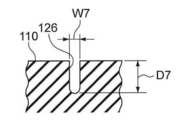
浅溝126は、アウト側セカンドリブ110の幅方向中央部よりも若干車両幅方向内側に形成されている。浅溝126は、矢印A方向側の端部が矢印A方向側とは反対側の端部に対して車両幅方向外側となるように、タイヤ周方向に対して若干傾斜して直線状に延びており、長手方向両端部がリブ内で終端している。
The shallow groove 126 is formed slightly inward in the vehicle width direction from the center in the width direction of the out-side second rib 110. The shallow groove 126 extends in a straight line with a slight inclination with respect to the tire circumferential direction so that the end on the arrow A direction side is outside the vehicle width direction with respect to the end opposite to the arrow A direction side. Both ends in the longitudinal direction terminate in the rib.
この浅溝126の長手方向に対し直交する方向の断面は、図6に示すように、略U字形状を呈している。浅溝126は、第1周方向溝100、第2周方向溝102、第3周方向溝104、及び第4周方向溝106よりも溝幅が狭く、かつトップトレッド18が接地した際に閉じない溝幅、言い換えれば、互いに対向する一方の溝壁面と他方の溝壁面とが接触しないような溝幅を有していることが好ましい。
The cross section in the direction perpendicular to the longitudinal direction of the shallow groove 126 is substantially U-shaped as shown in FIG. The shallow groove 126 is narrower than the first circumferential groove 100, the second circumferential groove 102, the third circumferential groove 104, and the fourth circumferential groove 106, and is closed when the top tread 18 is grounded. It is preferable that the groove width is such that there is no contact between one groove wall surface facing the other and the other groove wall surface.
浅溝126の溝深さD7は、第1周方向溝100、第2周方向溝102、第3周方向溝104、及び第4周方向溝106の溝深さよりも浅く形成することが好ましい。本実施形態の浅溝126は、長さが20mm、溝幅が2mm、溝深さが6.5mmである。
The groove depth D7 of the shallow groove 126 is preferably formed to be shallower than the groove depths of the first circumferential groove 100, the second circumferential groove 102, the third circumferential groove 104, and the fourth circumferential groove 106. The shallow groove 126 of this embodiment has a length of 20 mm, a groove width of 2 mm, and a groove depth of 6.5 mm.
浅溝126が、アウト側セカンドリブ110の圧縮剛性低減部とされており、アウト側セカンドリブ110の非横断サイプ124と非横断サイプ124との間のブロック状部分の圧縮剛性を低減している。
The shallow groove 126 is a compression rigidity reducing portion of the out side second rib 110, and the compression rigidity of the block-like portion between the non-crossing sipe 124 and the non-crossing sipe 124 of the out side second rib 110 is reduced. .
浅溝127は、アウト側セカンドリブ110の第2周方向溝102側に形成されており、第1幅方向サイプ部124Aの延長線上に配置されている。浅溝127の長手方向に対し直交する方向の断面は、図7に示すように、略U字形状を呈している。浅溝127は、溝幅W8が浅溝126よりも狭く、溝深さD8が浅溝126よりも浅く形成されている。本実施形態の浅溝127は、溝幅W8が1mm、溝深さD8が2mmである。なお、浅溝127は、後述する第2周方向溝102の溝壁に形成される浅溝134に連結されている。
The shallow groove 127 is formed on the second circumferential groove 102 side of the out-side second rib 110 and is disposed on an extension line of the first width direction sipe portion 124A. The cross section in the direction orthogonal to the longitudinal direction of the shallow groove 127 is substantially U-shaped as shown in FIG. The shallow groove 127 is formed such that the groove width W 8 is narrower than the shallow groove 126 and the groove depth D 8 is shallower than the shallow groove 126. The shallow groove 127 of the present embodiment has a groove width W8 of 1 mm and a groove depth D8 of 2 mm. The shallow groove 127 is connected to a shallow groove 134 formed in the groove wall of the second circumferential groove 102 described later.
(センターリブ)
センターリブ112には、第1傾斜溝128と第2傾斜溝130とがタイヤ周方向に間隔を開けて交互に配置されている。 (Center rib)
In thecenter rib 112, the first inclined grooves 128 and the second inclined grooves 130 are alternately arranged at intervals in the tire circumferential direction.
センターリブ112には、第1傾斜溝128と第2傾斜溝130とがタイヤ周方向に間隔を開けて交互に配置されている。 (Center rib)
In the
第1傾斜溝128は、第2周方向溝102から第3周方向溝104に向けてタイヤ幅方向に対して傾斜して延び、後述する短溝132を介して第3周方向溝104に接続されている。
The first inclined groove 128 extends inclined from the second circumferential groove 102 toward the third circumferential groove 104 with respect to the tire width direction, and is connected to the third circumferential groove 104 via a short groove 132 described later. Has been.
第1傾斜溝128は、車両幅方向内側の端部が車両幅方向外側の端部よりも矢印A方向側となるようにタイヤ幅方向に対して傾斜している。言い換えれば、第1傾斜溝128は、トップトレッド平面視で右上がりに傾斜している。なお、第1傾斜溝128のタイヤ幅方向に対する傾斜角度は、略45°に設定されている。
The first inclined groove 128 is inclined with respect to the tire width direction so that the end portion on the inner side in the vehicle width direction is closer to the arrow A direction side than the end portion on the outer side in the vehicle width direction. In other words, the first inclined groove 128 is inclined upward in the plan view of the top tread. The inclination angle of the first inclined groove 128 with respect to the tire width direction is set to approximately 45 °.
この第1傾斜溝128の長手方向に対し直交する方向の断面は、図8に示すように、略U字形状を呈している。第1傾斜溝128の溝幅W9は、第1周方向溝100、第2周方向溝102、第3周方向溝104、及び第4周方向溝106よりも狭く、トップトレッド18が接地した際に閉じない溝幅、言い換えれば、互いに対向する一方の溝壁面と他方の溝壁面とが接触しないような溝幅を有している。本実施形態の第1傾斜溝128は、溝幅W9が3.2mm、溝深さD9が6.5mmである。
The cross section in the direction perpendicular to the longitudinal direction of the first inclined groove 128 has a substantially U shape as shown in FIG. The groove width W9 of the first inclined groove 128 is narrower than the first circumferential groove 100, the second circumferential groove 102, the third circumferential groove 104, and the fourth circumferential groove 106, and when the top tread 18 is grounded. In other words, the groove width is such that one groove wall surface facing each other and the other groove wall surface do not contact each other. The first inclined groove 128 of the present embodiment has a groove width W9 of 3.2 mm and a groove depth D9 of 6.5 mm.
センターリブ112には、この第1傾斜溝128の車両幅方向内側の端部から第3周方向溝104に向けて延びて、第3周方向溝104に接続する短溝132が形成されている。短溝132は、タイヤ幅方向に対して第1傾斜溝128とは反対方向に傾斜している。言い換えれば、短溝132は、トップトレッド平面視で左上がりに傾斜している。短溝132は、第1傾斜溝128と同じ溝深さに形成されている。短溝132は、第1傾斜溝128よりも溝幅が狭く形成されているが、トップトレッド18が接地した際に閉じない溝幅、言い換えれば、互いに対向する一方の溝壁面と他方の溝壁面とが接触しないような溝幅を有している。
The center rib 112 is formed with a short groove 132 that extends from the inner end in the vehicle width direction of the first inclined groove 128 toward the third circumferential groove 104 and is connected to the third circumferential groove 104. . The short groove 132 is inclined in the direction opposite to the first inclined groove 128 with respect to the tire width direction. In other words, the short groove 132 is inclined upward in the plan view of the top tread. The short groove 132 is formed at the same groove depth as the first inclined groove 128. The short groove 132 is formed narrower than the first inclined groove 128, but does not close when the top tread 18 is grounded, in other words, one groove wall surface and the other groove wall surface facing each other. Has a groove width that does not come into contact with the groove.
第2傾斜溝130は、第2周方向溝102から車両幅方向内側へ向けて傾斜して延びており、センターリブ112のリブ内における第3周方向溝104の近傍で終端している。第2傾斜溝130は、車両幅方向内側の端部が車両幅方向外側の端部よりも矢印A方向側となるようにタイヤ幅方向に対して傾斜している。言い換えれば、第2傾斜溝130は、トップトレッド平面視で右上がりに傾斜しており、第1傾斜溝128と平行に設けられている。
The second inclined groove 130 extends from the second circumferential groove 102 in an inward direction in the vehicle width direction and terminates in the vicinity of the third circumferential groove 104 in the rib of the center rib 112. The second inclined groove 130 is inclined with respect to the tire width direction so that the end portion on the inner side in the vehicle width direction is closer to the arrow A direction side than the end portion on the outer side in the vehicle width direction. In other words, the second inclined groove 130 is inclined upward in the plan view of the top tread, and is provided in parallel with the first inclined groove 128.
第2傾斜溝130の長手方向に対し直交する方向の断面は、図9に示すように、略U字形状を呈している。第2傾斜溝130の溝幅W10は、第1周方向溝100、第2周方向溝102、第3周方向溝104、及び第4周方向溝106よりも狭く、トップトレッド18が接地した際に閉じない溝幅、言い換えれば、互いに対向する一方の溝壁面と他方の溝壁面とが接触しないような溝幅を有している。本実施形態の第2傾斜溝130は、溝幅W10が3.4mm、溝深さD10が6.5mmである。
The cross section in the direction orthogonal to the longitudinal direction of the second inclined groove 130 is substantially U-shaped as shown in FIG. The groove width W10 of the second inclined groove 130 is narrower than the first circumferential groove 100, the second circumferential groove 102, the third circumferential groove 104, and the fourth circumferential groove 106, and when the top tread 18 is grounded. In other words, the groove width is such that one groove wall surface facing each other and the other groove wall surface do not contact each other. The second inclined groove 130 of the present embodiment has a groove width W10 of 3.4 mm and a groove depth D10 of 6.5 mm.
図1、及び図2に示すように、第2周方向溝102の溝壁には、アウト側セカンドリブ110の浅溝127とセンターリブ112の第2傾斜溝130とを連結する浅溝134が形成されている。浅溝134は、浅溝127と連結される側の端部が、第2傾斜溝130と連結される側の端部よりも車両幅方向外側に位置するようにタイヤ周方向に対して45°以下の比較的小さい角度で傾斜している。
As shown in FIGS. 1 and 2, the groove wall of the second circumferential groove 102 has a shallow groove 134 that connects the shallow groove 127 of the out-side second rib 110 and the second inclined groove 130 of the center rib 112. Is formed. The shallow groove 134 is 45 ° with respect to the tire circumferential direction so that the end connected to the shallow groove 127 is located on the outer side in the vehicle width direction than the end connected to the second inclined groove 130. It is inclined at the following relatively small angle.
図2に示すように、第2周方向溝102の溝壁を基準として計測する浅溝134の溝深D11さは0.5mmである。なお、浅溝134と浅溝127とは図10に示すように溝底同士が連結されており、浅溝134と第2傾斜溝130とは図11に示すように溝底同士が連結されている。
As shown in FIG. 2, the groove depth D11 of the shallow groove 134 measured with reference to the groove wall of the second circumferential groove 102 is 0.5 mm. The shallow groove 134 and the shallow groove 127 are connected to each other as shown in FIG. 10, and the shallow groove 134 and the second inclined groove 130 are connected to each other as shown in FIG. Yes.
(イン側セカンドリブ)
イン側セカンドリブ114には、サイプ140と細溝142とがタイヤ周方向に間隔を開けて交互に配置されている。 (In side second rib)
On the in-sidesecond rib 114, sipes 140 and narrow grooves 142 are alternately arranged at intervals in the tire circumferential direction.
イン側セカンドリブ114には、サイプ140と細溝142とがタイヤ周方向に間隔を開けて交互に配置されている。 (In side second rib)
On the in-side
サイプ140は、トップトレッド18が接地した際に、閉じてしまう溝幅、言い換えれば、互いに対向する一方の溝壁面と他方の溝壁面とが接触するような溝幅を有している。サイプ140は、一方の端部が第3周方向溝104に接続され、他方の端部が第4周方向溝106に接続されている。言い換えれば、サイプ140は、イン側セカンドリブ114をタイヤ幅方向に横断している。
The sipe 140 has a groove width that closes when the top tread 18 is grounded, in other words, a groove width such that one groove wall surface facing the other and the other groove wall surface are in contact with each other. The sipe 140 has one end connected to the third circumferential groove 104 and the other end connected to the fourth circumferential groove 106. In other words, the sipe 140 crosses the in-side second rib 114 in the tire width direction.
サイプ140は、車両幅方向外側の端部が車両幅方向内側の端部よりも矢印A方向側となるようにタイヤ幅方向に対して傾斜している。言い換えれば、このサイプ140は、トレッド平面視で左上がりに傾斜している。サイプ140のタイヤ幅方向に対する傾斜角度は、45°以下に設定されている。なお、本実施形態のサイプ140は、第1周方向溝100、第2周方向溝102、第3周方向溝104、及び第4周方向溝106よりも浅く形成されている。
The sipe 140 is inclined with respect to the tire width direction so that the end portion on the outer side in the vehicle width direction is closer to the arrow A direction side than the end portion on the inner side in the vehicle width direction. In other words, the sipe 140 is inclined upward in the tread plan view. The inclination angle of the sipe 140 with respect to the tire width direction is set to 45 ° or less. Note that the sipe 140 of this embodiment is formed shallower than the first circumferential groove 100, the second circumferential groove 102, the third circumferential groove 104, and the fourth circumferential groove 106.
細溝142は、両端部がイン側セカンドリブ114内で終端しており、サイプ140とサイプ140との間に、2つの細溝142が間隔を開けて直線上に配置されている。これら2つの細溝142は、サイプ140と平行に形成されている。
Both ends of the narrow groove 142 terminate in the in-side second rib 114, and the two narrow grooves 142 are arranged on a straight line with a gap between the sipe 140 and the sipe 140. These two narrow grooves 142 are formed in parallel with the sipe 140.
細溝142の長手方向に対し直交する方向の断面は、図12に示すように、略U字形状を呈している。細溝142の溝幅W11は、第1周方向溝100、第2周方向溝102、第3周方向溝104、及び第4周方向溝106よりも狭く、かつトップトレッド18が接地した際に閉じない溝幅、言い換えれば、互いに対向する一方の溝壁面と他方の溝壁面とが接触しないような溝幅を有していることが好ましい。
The cross section in the direction orthogonal to the longitudinal direction of the narrow groove 142 is substantially U-shaped as shown in FIG. The groove width W11 of the narrow groove 142 is narrower than the first circumferential groove 100, the second circumferential groove 102, the third circumferential groove 104, and the fourth circumferential groove 106, and when the top tread 18 is grounded. It is preferable to have a groove width that does not close, in other words, a groove width that prevents one groove wall surface and the other groove wall surface facing each other from contacting each other.
細溝142の溝深さD11は、第1周方向溝100、第2周方向溝102、第3周方向溝104、及び第4周方向溝106の溝深さよりも浅く形成することが好ましい。本実施形態の細溝142は、長さが8.5mm、溝幅W11が1mm、溝深さD11が2mmである。なお、これらの細溝142が、圧縮剛性低減部とされている。
The groove depth D11 of the narrow groove 142 is preferably formed to be shallower than the groove depths of the first circumferential groove 100, the second circumferential groove 102, the third circumferential groove 104, and the fourth circumferential groove 106. The narrow groove 142 of this embodiment has a length of 8.5 mm, a groove width W11 of 1 mm, and a groove depth D11 of 2 mm. These narrow grooves 142 serve as a compression rigidity reducing portion.
(イン側ショルダーリブ)
イン側ショルダーリブ116には、イン側幅方向溝144、及びサイプ146が間隔を開けてタイヤ周方向に交互に形成されている。 (Inside shoulder rib)
The in-side shoulder rib 116 is formed with in-side width direction grooves 144 and sipes 146 alternately in the tire circumferential direction at intervals.
イン側ショルダーリブ116には、イン側幅方向溝144、及びサイプ146が間隔を開けてタイヤ周方向に交互に形成されている。 (Inside shoulder rib)
The in-
イン側幅方向溝144は、車両幅方向外側の端部がトップトレッド18の接地端18Eよりも車両幅方向外側に位置し、イン側ショルダーリブ116内において、第4周方向溝106の近傍で終端している。また、イン側幅方向溝144は、車両幅方向内側の端部が接地端18Eよりも車両幅方向内側に位置している。
The in-side width direction groove 144 has an end portion on the outer side in the vehicle width direction located on the outer side in the vehicle width direction with respect to the ground contact end 18E of the top tread 18, and in the vicinity of the fourth circumferential groove 106 in the in-side shoulder rib 116. It is terminated. Further, the in-side width direction groove 144 has an end portion on the inner side in the vehicle width direction located on the inner side in the vehicle width direction than the ground contact end 18E.
イン側幅方向溝144は、車両幅方向外側の端部が車両幅方向内側の端部よりも矢印A方向側となるようにタイヤ幅方向に対して傾斜している。言い換えれば、イン側幅方向溝144は、トップトレッド平面視で左上がりに傾斜している。なお、本実施形態では、イン側幅方向溝144の溝幅中心線がタイヤ幅方向に対して45°以下で傾斜している。
The in-side width direction groove 144 is inclined with respect to the tire width direction so that the end portion on the outer side in the vehicle width direction is closer to the arrow A direction side than the end portion on the inner side in the vehicle width direction. In other words, the in-side width direction groove 144 is inclined upward in the top tread plan view. In the present embodiment, the groove width center line of the in-side width direction groove 144 is inclined at 45 ° or less with respect to the tire width direction.
イン側幅方向溝144の長手方向に対し直交する方向の断面は、図13に示すように、略U字形状を呈している。イン側幅方向溝144の溝幅W12は、第1周方向溝100、第2周方向溝102、第3周方向溝104、及び第4周方向溝106の溝幅よりも狭く、トップトレッド18が接地した際に閉じない溝幅、言い換えれば、互いに対向する一方の溝壁面と他方の溝壁面とが接触しないような溝幅を有している。
The cross section in the direction orthogonal to the longitudinal direction of the in-side width direction groove 144 is substantially U-shaped as shown in FIG. The groove width W12 of the in-side width direction groove 144 is narrower than the groove widths of the first circumferential groove 100, the second circumferential groove 102, the third circumferential groove 104, and the fourth circumferential groove 106, and the top tread 18 Has a groove width that does not close when grounded, in other words, a groove width that prevents one groove wall surface and the other groove wall surface facing each other from contacting each other.
また、イン側幅方向溝144の溝深さD12は、第1周方向溝100、第2周方向溝102、第3周方向溝104、及び第4周方向溝106の溝深さよりも浅い。本実施形態のイン側幅方向溝144の溝幅W12は3.8mm、溝深さD12は5.2mmである。
Further, the groove depth D12 of the in-side width direction groove 144 is shallower than the groove depths of the first circumferential groove 100, the second circumferential groove 102, the third circumferential groove 104, and the fourth circumferential groove 106. The groove width W12 of the in-side width direction groove 144 of the present embodiment is 3.8 mm, and the groove depth D12 is 5.2 mm.
ここで、路面と接触可能なトップトレッド18の外周面の面積である一方の接地端18Eと他方の接地端18Eとの間のタイヤ外周面の面積、言い換えればトップトレッド18の接地幅TW×トップトレッド18のタイヤ1周分(即ち全周)の周方向長さ(即ち、周長)で得られる面積に対して、一つのイン側幅方向溝144の開口面積は、0.02%以下とする。
なお、トップトレッド18の接地面積、言い換えれば、トップトレッド18の実際に路面と接触している部分の面積に対して、一つのイン側幅方向溝144の開口面積は、1.5%以下とする。 Here, the area of the outer circumferential surface of the tire between one groundingend 18E and the other grounding end 18E, which is the area of the outer circumferential surface of the top tread 18 that can come into contact with the road surface, in other words, the grounding width TW × top of the top tread 18 The opening area of one in-side width direction groove 144 is 0.02% or less with respect to the area obtained by the circumferential length (that is, the circumferential length) of one tread 18 of the tire (that is, the entire circumference). To do.
The opening area of one in-sidewidth direction groove 144 is 1.5% or less with respect to the contact area of the top tread 18, in other words, the area of the top tread 18 that is actually in contact with the road surface. To do.
なお、トップトレッド18の接地面積、言い換えれば、トップトレッド18の実際に路面と接触している部分の面積に対して、一つのイン側幅方向溝144の開口面積は、1.5%以下とする。 Here, the area of the outer circumferential surface of the tire between one grounding
The opening area of one in-side
さらに、ベルト層14の配置されている領域、言い換えれば、ベルト層14のタイヤ幅方向の一方の端部14Eと他方の端部14Eとの間の領域において、全てのイン側幅方向溝144をタイヤ周方向に投影した領域、言い換えれば、ベルト層14の端部14Eと、全てのイン側幅方向溝144の内で最もタイヤ赤道面CL側に位置するイン側幅方向溝144の端部を通るタイヤ周方向に延びる仮想線FL2との間のイン側幅方向溝配置領域A2の面積(トップトレッド18の外周面において、ベルト層14の端部14Eからイン側幅方向溝144のタイヤ赤道面CL側の端部までのタイヤ幅方向に沿って計測した長さ×トップトレッド18の外周面のタイヤ1周分(即ち、全周))のタイヤ周方向長さ(即ち、周長))に占める一つのイン側幅方向溝144の開口面積は、1.5%以下とすることが好ましい。
なお、トップトレッド18の接地面におけるイン側幅方向溝配置領域A2の面積に占める、一つのイン側幅方向溝144の開口面積は、5%以下とする。 Further, in the region where thebelt layer 14 is arranged, in other words, in the region between one end 14E and the other end 14E in the tire width direction of the belt layer 14, all the in-side width direction grooves 144 are formed. The region projected in the tire circumferential direction, in other words, the end portion 14E of the belt layer 14 and the end portion of the in-side width direction groove 144 located closest to the tire equatorial plane CL among all the in-side width direction grooves 144 The area of the in-side width direction groove arrangement region A2 between the imaginary line FL2 extending in the tire circumferential direction (the tire equatorial surface of the in-side width direction groove 144 from the end 14E of the belt layer 14 on the outer peripheral surface of the top tread 18) The length measured along the tire width direction to the end on the CL side × the length of the outer circumferential surface of the top tread 18 (ie, the circumference of the tire) (ie, the circumference)) One inn that occupies The opening area of the width direction groove 144 is preferably set to 1.5% or less.
The opening area of one in-side width direction groove 144 occupying the area of the in-side width direction groove arrangement region A2 on the ground contact surface of thetop tread 18 is 5% or less.
なお、トップトレッド18の接地面におけるイン側幅方向溝配置領域A2の面積に占める、一つのイン側幅方向溝144の開口面積は、5%以下とする。 Further, in the region where the
The opening area of one in-side width direction groove 144 occupying the area of the in-side width direction groove arrangement region A2 on the ground contact surface of the
また、トップトレッド18の接地幅TWの範囲内において、イン側幅方向溝144のタイヤ幅方向に沿って計測した長さL2は、接地幅TWに対して10~20%の範囲内に設定することが好ましい。
Further, the length L2 measured along the tire width direction of the in-side width direction groove 144 within the range of the contact width TW of the top tread 18 is set within a range of 10 to 20% with respect to the contact width TW. It is preferable.
イン側幅方向溝144のタイヤ周方向のピッチに対するイン側幅方向溝144の溝幅(平均値)の比率、言い換えれば、タイヤ周方向に隣接する一方のイン側幅方向溝144の溝幅中心線と他方のイン側幅方向溝144の溝幅中心線とのタイヤ周方向に沿って計測する距離に対する、イン側幅方向溝144の溝幅(平均値)の比率は、8~15%の範囲内とすることが好ましい。
The ratio of the groove width (average value) of the in-side width direction groove 144 to the pitch of the in-side width direction groove 144 in the tire circumferential direction, in other words, the groove width center of one in-side width direction groove 144 adjacent in the tire circumferential direction The ratio of the groove width (average value) of the in-side width direction groove 144 to the distance measured along the tire circumferential direction between the line and the groove width center line of the other in-side width direction groove 144 is 8 to 15%. It is preferable to be within the range.
サイプ146は、トップトレッド18が接地した際に、閉じてしまう溝幅、言い換えれば、互いに対向する一方の溝壁面と他方の溝壁面とが接触するような溝幅を有している。サイプ146は、イン側幅方向溝144と平行に形成され、一方の端部が第4周方向溝106に接続され、他方の端部がトップトレッド18の接地端18Eよりも車両幅方向内側に位置している。言い換えれば、サイプ146は、トップトレッド18の接地面内でイン側ショルダーリブ116をタイヤ幅方向に横断している。なお、サイプ146は、イン側セカンドリブ114のサイプ140の延長線上に配置されている。
The sipe 146 has a groove width that closes when the top tread 18 is grounded, in other words, a groove width such that one groove wall face and the other groove wall face each other contact each other. The sipe 146 is formed in parallel with the in-side width direction groove 144, one end is connected to the fourth circumferential groove 106, and the other end is on the inner side in the vehicle width direction than the grounding end 18 </ b> E of the top tread 18. positioned. In other words, the sipe 146 crosses the in-side shoulder rib 116 in the tire width direction within the contact surface of the top tread 18. The sipe 146 is disposed on an extension line of the sipe 140 of the in-side second rib 114.
なお、本実施形態では、タイヤ骨格部材12の一方のタイヤ片12Aと他方のタイヤ片12Aとを接合している接合部材30のタイヤ径方向外側に配置されているセンターリブ112以外のアウト側ショルダーリブ108、アウト側セカンドリブ110、及びイン側セカンドリブ114に、圧縮剛性低減部(ピンサイプ122、浅溝126、及び細溝142)が設けられている。
In the present embodiment, the outer shoulder other than the center rib 112 disposed on the outer side in the tire radial direction of the joining member 30 joining the one tire piece 12A and the other tire piece 12A of the tire frame member 12. The ribs 108, the out-side second rib 110, and the in-side second rib 114 are provided with compression rigidity reducing portions (pin sipes 122, shallow grooves 126, and narrow grooves 142).
本実施形態のタイヤ10は、予め成形されたタイヤ骨格部材12の外面に、ベルト層14、ベルト上補強層15、サイド補強層13を配置し、さらにその外面に、後にサイドトレッド16、及びトップトレッド18となる未加硫ゴムを配置したグリーンタイヤを得て、このグリーンタイヤを加硫モールドに装填して加硫成形することで製造される。
In the tire 10 of the present embodiment, a belt layer 14, a belt upper reinforcing layer 15, and a side reinforcing layer 13 are disposed on the outer surface of a preformed tire frame member 12. It is manufactured by obtaining a green tire on which unvulcanized rubber to be the tread 18 is arranged, and loading the green tire into a vulcanization mold and vulcanizing it.
(作用、効果)
本実施形態のタイヤ10では、トップトレッド18の全接地面の面積に対して、一つの第1幅方向溝118の開口面積が0.02%以下に設定されている。また、トップトレッド18の接地面内における1個当たりの第1幅方向溝118の開口面積が、トップトレッド18の接地面の面積に対して1.5%以下に設定されている。
このため、加硫成形の際、第1幅方向溝118を形成するためのモールドの突起からの押圧力によってベルト層14が撓む範囲をタイヤ周方向に小さくすることができ、その結果、ベルト層14に隣接するタイヤ骨格部材12のクラウン部24の撓む範囲をタイヤ周方向に小さくすることができる。 (Function, effect)
In thetire 10 of this embodiment, the opening area of one first width direction groove 118 is set to 0.02% or less with respect to the area of the entire ground contact surface of the top tread 18. Further, the opening area of the first width direction groove 118 per piece in the grounding surface of the top tread 18 is set to 1.5% or less with respect to the area of the grounding surface of the top tread 18.
For this reason, at the time of vulcanization molding, the range in which thebelt layer 14 bends due to the pressing force from the mold projection for forming the first width direction groove 118 can be reduced in the tire circumferential direction. As a result, the belt A range in which the crown portion 24 of the tire frame member 12 adjacent to the layer 14 bends can be reduced in the tire circumferential direction.
本実施形態のタイヤ10では、トップトレッド18の全接地面の面積に対して、一つの第1幅方向溝118の開口面積が0.02%以下に設定されている。また、トップトレッド18の接地面内における1個当たりの第1幅方向溝118の開口面積が、トップトレッド18の接地面の面積に対して1.5%以下に設定されている。
このため、加硫成形の際、第1幅方向溝118を形成するためのモールドの突起からの押圧力によってベルト層14が撓む範囲をタイヤ周方向に小さくすることができ、その結果、ベルト層14に隣接するタイヤ骨格部材12のクラウン部24の撓む範囲をタイヤ周方向に小さくすることができる。 (Function, effect)
In the
For this reason, at the time of vulcanization molding, the range in which the
さらに、本実施形態のタイヤ10では、第1幅方向溝118の配置されている第1幅方向溝配置領域A1において、第1幅方向溝配置領域A1の面積に占める、第1幅方向溝118の1個当たりの開口面積が5%以下に設定されているため、タイヤ骨格部材12のクラウン部24の車両幅方向外側部分の撓む範囲をタイヤ周方向により小さくすることができる。
Furthermore, in the tire 10 of the present embodiment, the first width direction groove 118 occupying the area of the first width direction groove arrangement region A1 in the first width direction groove arrangement region A1 where the first width direction groove 118 is arranged. Since the opening area per piece is set to 5% or less, the bending range of the outer portion in the vehicle width direction of the crown portion 24 of the tire frame member 12 can be reduced in the tire circumferential direction.
なお、第1幅方向溝118は、タイヤ幅方向に対する溝幅中心線の角度が45°以下であるため、アウト側ショルダーリブ108の第1幅方向溝118と第1幅方向溝118との間の陸部分におけるタイヤ幅方向の剛性を確保することができ、また、タイヤ幅方向への排水性を向上できる。
In addition, since the angle of the groove width center line with respect to the tire width direction is 45 ° or less, the first width direction groove 118 is between the first width direction groove 118 and the first width direction groove 118 of the out-side shoulder rib 108. The rigidity in the tire width direction in the land portion can be ensured, and the drainage in the tire width direction can be improved.
トップトレッド18の接地幅TWに対して、接地面内における第1幅方向溝118のタイヤ幅方向に沿った方向に計測した長さL1の最低値を5%に設定しているので、アウト側ショルダーリブ108の第1幅方向溝118周辺の領域においてタイヤ幅方向の排水性を確保することができる。なお、タイヤ骨格部材12の変形が広範囲に及ばないように、接地幅TWに対して、第1幅方向溝118のタイヤ幅方向に沿った方向に計測した長さの最大値を20%に設定することが好ましい。
Since the minimum value of the length L1 measured in the direction along the tire width direction of the first width direction groove 118 in the ground contact surface is set to 5% with respect to the ground contact width TW of the top tread 18, the out side The drainage performance in the tire width direction can be ensured in the region around the first width direction groove 118 of the shoulder rib 108. In addition, the maximum value of the length measured in the direction along the tire width direction of the first width direction groove 118 is set to 20% with respect to the contact width TW so that the deformation of the tire frame member 12 does not reach a wide range. It is preferable to do.
本実施形態のタイヤ10では、トップトレッド18の全接地面の面積に対して、一つのイン側幅方向溝144の開口面積が0.02%以下に設定されている。また、トップトレッド18の接地面内における1個当たりのイン側幅方向溝144の開口面積が、トップトレッド18の接地面の面積に対して1.5%以下に設定されている。
このため、加硫成形の際、イン側幅方向溝144を形成するためのモールドの突起よりベルト層14が撓む範囲をタイヤ周方向に小さくすることができ、その結果、ベルト層14に隣接するタイヤ骨格部材12のクラウン部24の撓む範囲をタイヤ周方向に小さくすることができる。 In thetire 10 of this embodiment, the opening area of one in-side width direction groove 144 is set to 0.02% or less with respect to the area of the entire ground contact surface of the top tread 18. Further, the opening area of the in-side width direction groove 144 in the ground contact surface of the top tread 18 is set to 1.5% or less with respect to the area of the ground contact surface of the top tread 18.
For this reason, at the time of vulcanization molding, the range in which thebelt layer 14 bends from the projection of the mold for forming the in-side width direction groove 144 can be reduced in the tire circumferential direction, and as a result, adjacent to the belt layer 14. The range in which the crown portion 24 of the tire frame member 12 bends can be reduced in the tire circumferential direction.
このため、加硫成形の際、イン側幅方向溝144を形成するためのモールドの突起よりベルト層14が撓む範囲をタイヤ周方向に小さくすることができ、その結果、ベルト層14に隣接するタイヤ骨格部材12のクラウン部24の撓む範囲をタイヤ周方向に小さくすることができる。 In the
For this reason, at the time of vulcanization molding, the range in which the
さらに、本実施形態のタイヤ10では、イン側幅方向溝144の配置されているイン側幅方向溝配置領域A2において、イン側幅方向溝配置領域A2の面積に占める、イン側幅方向溝144の1個当たりの開口面積が5%以下に設定されているため、タイヤ骨格部材12のクラウン部24の車両幅方向内側部分の撓む範囲をよりタイヤ周方向に小さくすることができる。
Furthermore, in the tire 10 of the present embodiment, the in-side width direction groove 144 occupies the area of the in-side width direction groove arrangement region A2 in the in-side width direction groove arrangement region A2 where the in-side width direction groove 144 is arranged. Since the opening area per piece is set to 5% or less, the bending range of the inner portion in the vehicle width direction of the crown portion 24 of the tire frame member 12 can be further reduced in the tire circumferential direction.
なお、イン側幅方向溝144は、タイヤ幅方向に対する溝幅中心線の角度が45°以下であるため、イン側ショルダーリブ116のイン側幅方向溝144とイン側幅方向溝144との間の陸部分におけるタイヤ幅方向の剛性を確保することができ、また、タイヤ幅方向への排水性を向上できる。
In addition, since the angle of the groove width center line with respect to the tire width direction is 45 ° or less, the in-side width direction groove 144 is between the in-side width direction groove 144 and the in-side width direction groove 144 of the in-side shoulder rib 116. The rigidity in the tire width direction in the land portion can be ensured, and the drainage in the tire width direction can be improved.
トップトレッド18の接地幅TWに対して、接地面内におけるイン側幅方向溝144のタイヤ幅方向に沿った方向に計測した長さL2の最低値を10%に設定しているので、イン側ショルダーリブ116のイン側幅方向溝144周辺の領域においてタイヤ幅方向の排水性を確保することができる。なお、タイヤ骨格部材12の変形が広範囲に及ばないように、接地幅TWに対して、イン側幅方向溝144のタイヤ幅方向に沿った方向に計測した長さの最大値を20%に設定することが好ましい。
The minimum value of the length L2 measured in the direction along the tire width direction of the in-side width direction groove 144 in the contact surface with respect to the contact width TW of the top tread 18 is set to 10%. Drainability in the tire width direction can be ensured in the area around the in-side width direction groove 144 of the shoulder rib 116. In order to prevent deformation of the tire frame member 12 over a wide range, the maximum value of the length measured in the direction along the tire width direction of the in-side width direction groove 144 is set to 20% with respect to the contact width TW. It is preferable to do.
本実施形態のタイヤ10では、トップトレッド18に、タイヤ周方向に延びる第1周方向溝100、第2周方向溝102、第3周方向溝104、及び第4周方向溝106が形成されており、これらの溝は、ウエット路面走行時、トップトレッド18と路面との間の水をタイヤ接地面外へ排出する排水用の主溝として機能する。
In the tire 10 of the present embodiment, a first circumferential groove 100, a second circumferential groove 102, a third circumferential groove 104, and a fourth circumferential groove 106 extending in the tire circumferential direction are formed on the top tread 18. These grooves function as drainage main grooves for discharging water between the top tread 18 and the road surface to the outside of the tire ground contact surface when traveling on a wet road surface.
これら第1周方向溝100、第2周方向溝102、第3周方向溝104、及び第4周方向溝106によって、トップトレッド18には、陸部としてのアウト側ショルダーリブ108、アウト側セカンドリブ110、センターリブ112、イン側セカンドリブ114、及びイン側ショルダーリブ116が区画されている。
By the first circumferential groove 100, the second circumferential groove 102, the third circumferential groove 104, and the fourth circumferential groove 106, the top tread 18 has an out-side shoulder rib 108 and an out-side second as a land portion. A rib 110, a center rib 112, an in-side second rib 114, and an in-side shoulder rib 116 are defined.
アウト側ショルダーリブ108には、複数の第1幅方向溝118、及びサイプ120がタイヤ周方向に間隔を開けて形成されており、これによってアウト側ショルダーリブ108のタイヤ周方向の剛性、及びタイヤ幅方向の剛性が適度に低減されている。また、ウエット路面走行時、第1幅方向溝118によってアウト側ショルダーリブ108と路面との間の水をタイヤ外側へ排水することができる。
A plurality of first width direction grooves 118 and sipes 120 are formed in the outer side shoulder rib 108 at intervals in the tire circumferential direction, whereby the rigidity of the outer side shoulder rib 108 in the tire circumferential direction and tire The rigidity in the width direction is moderately reduced. Further, when running on a wet road surface, water between the out-side shoulder rib 108 and the road surface can be drained to the outside of the tire by the first width direction groove 118.
アウト側ショルダーリブ108の第1幅方向溝118と第1幅方向溝118との間のブロック状部分には、第1幅方向溝118と平行に複数のピンサイプ122が形成されており、これによって該ブロック状部分の圧縮剛性を低減している。
A plurality of pin sipes 122 are formed in the block-like portion between the first width direction groove 118 and the first width direction groove 118 of the out side shoulder rib 108 in parallel with the first width direction groove 118, thereby The compression rigidity of the block-like portion is reduced.
このようにしてアウト側ショルダーリブ108の圧縮剛性を低減することで、アウト側ショルダーリブ108の振動がタイヤ骨格部材12を介して車両側に伝達し難くなり、騒音、及び乗り心地を改善可能となる。
By reducing the compression rigidity of the out-side shoulder rib 108 in this way, vibration of the out-side shoulder rib 108 becomes difficult to be transmitted to the vehicle side via the tire frame member 12, and noise and riding comfort can be improved. Become.
アウト側セカンドリブ110には、複数の非横断サイプ124がタイヤ周方向に間隔を開けて形成されており、これによってアウト側セカンドリブ110のタイヤ周方向の剛性、及びタイヤ幅方向の剛性が適度に低減されている。
A plurality of non-crossing sipes 124 are formed on the out-side second rib 110 at intervals in the tire circumferential direction, whereby the rigidity in the tire circumferential direction and the rigidity in the tire width direction of the out-side second rib 110 are moderate. Has been reduced.
アウト側セカンドリブ110の非横断サイプ124と非横断サイプ124との間のブロック状部分には、浅溝126が形成されており、これによって該ブロック状部分の圧縮剛性を低減している。このようにしてアウト側セカンドリブ110の圧縮剛性を低減することで、アウト側セカンドリブ110の振動がタイヤ骨格部材12を介して車両側に伝達し難くなり、騒音、及び乗り心地を改善可能となる。なお、浅溝126は、両端部がアウト側セカンドリブ110のリブ内で終端しており、アウト側セカンドリブ110をタイヤ幅方向に横断していないので、アウト側セカンドリブ110のタイヤ幅方向の剛性、及び周方向の剛性を不要に低下させる虞が無い。
A shallow groove 126 is formed in the block-like portion between the non-crossing sipe 124 and the non-crossing sipe 124 of the out-side second rib 110, thereby reducing the compression rigidity of the block-like portion. By reducing the compression rigidity of the out-side second rib 110 in this way, vibration of the out-side second rib 110 becomes difficult to be transmitted to the vehicle side via the tire frame member 12, and noise and riding comfort can be improved. Become. Note that the shallow groove 126 ends at both ends in the rib of the out-side second rib 110 and does not cross the out-side second rib 110 in the tire width direction. There is no risk of unnecessarily reducing the rigidity and the rigidity in the circumferential direction.
センターリブ112には、複数の第1傾斜溝128と第2傾斜溝130とがタイヤ周方向に間隔を開けて交互に配置されており、これによってセンターリブ112のタイヤ周方向の剛性、及びタイヤ幅方向の剛性が適度に低減されている。また、ウエット路面走行時、第1傾斜溝128と第2傾斜溝130によってセンターリブ112と路面との間の水を第2周方向溝102に排水することができる。
In the center rib 112, a plurality of first inclined grooves 128 and second inclined grooves 130 are alternately arranged at intervals in the tire circumferential direction, whereby the rigidity of the center rib 112 in the tire circumferential direction and the tire The rigidity in the width direction is moderately reduced. In addition, when running on a wet road surface, water between the center rib 112 and the road surface can be drained into the second circumferential groove 102 by the first inclined groove 128 and the second inclined groove 130.
イン側セカンドリブ114には、複数のサイプ140がタイヤ周方向に間隔を開けて形成されており、これによってイン側セカンドリブ114のタイヤ周方向の剛性、及びタイヤ幅方向の剛性が適度に低減されている。
A plurality of sipes 140 are formed on the in-side second rib 114 at intervals in the tire circumferential direction, whereby the rigidity in the tire circumferential direction and the stiffness in the tire width direction of the in-side second rib 114 are appropriately reduced. Has been. *
また、イン側セカンドリブ114のサイプ140とサイプ140との間のブロック状部分には、細溝142が形成されており、これにより該ブロック状部分の圧縮剛性を低減している。
Further, a narrow groove 142 is formed in a block-like portion between the sipe 140 and the sipe 140 of the in-side second rib 114, thereby reducing the compression rigidity of the block-like portion.
このようにしてイン側セカンドリブ114の圧縮剛性を低減することで、イン側セカンドリブ114の振動がタイヤ骨格部材12を介して車両側に伝達し難くなり、騒音、及び乗り心地を改善可能となる。
By reducing the compression rigidity of the in-side second rib 114 in this way, vibration of the in-side second rib 114 becomes difficult to be transmitted to the vehicle side via the tire skeleton member 12, and noise and riding comfort can be improved. Become.
イン側ショルダーリブ116には、イン側幅方向溝144、及びサイプ146が間隔を開けてタイヤ周方向に交互に形成されており、これにより、イン側ショルダーリブ116のタイヤ周方向の剛性、及びタイヤ幅方向の剛性が適度に低減されている。また、ウエット路面走行時、イン側幅方向溝144によってイン側ショルダーリブ116と路面との間の水をタイヤ外側へ排水することができる。
The in-side shoulder rib 116 is formed with in-side width direction grooves 144 and sipes 146 alternately in the tire circumferential direction at intervals, whereby the in-side shoulder rib 116 has rigidity in the tire circumferential direction, and The rigidity in the tire width direction is moderately reduced. Further, when running on a wet road surface, the water between the in-side shoulder rib 116 and the road surface can be drained to the outside of the tire by the in-side width direction groove 144.
このように、本実施形態のタイヤ10では、圧縮剛性低減部としてのピンサイプ122、浅溝126、及び細溝142を陸部の圧縮剛性の高い部分に設けたので、該圧縮剛性の高い部分の圧縮剛性が低減され、陸部の振動がタイヤ骨格部材12を介して車両側に伝達し難くなり、騒音、及び乗り心地を改善可能となる。
As described above, in the tire 10 of the present embodiment, the pin sipes 122, the shallow grooves 126, and the narrow grooves 142 as the compression rigidity reducing portion are provided in the high compression rigidity portion of the land portion. The compression rigidity is reduced, and the vibration of the land portion becomes difficult to be transmitted to the vehicle side via the tire frame member 12, and noise and riding comfort can be improved.
なお、本実施形態のタイヤ10では、センターリブ112、イン側ショルダーリブ116に圧縮剛性低減部が設けられていないが、上記ピンサイプ122、浅溝126、及び細溝142を設けてもよい。
In the tire 10 of the present embodiment, the center rib 112 and the in-side shoulder rib 116 are not provided with the compression rigidity reducing portion, but the pin sipe 122, the shallow groove 126, and the narrow groove 142 may be provided.
[その他の実施形態]
以上、本発明の一実施形態について説明したが、本発明は、上記に限定されるものでなく、上記以外にも、その主旨を逸脱しない範囲内において種々変形して実施可能であることは勿論である。 [Other Embodiments]
Although one embodiment of the present invention has been described above, the present invention is not limited to the above, and other various modifications can be made without departing from the spirit of the present invention. It is.
上記実施形態では、第1幅方向溝118の配置されている第1幅方向溝配置領域A1において、第1幅方向溝配置領域A1の面積に占める、第1幅方向溝118の1個当たりの開口面積が5%以下に設定されていたが、場合によっては5%以下に設定しなくてもよい。
In the above embodiment, in the first width direction groove arrangement region A1 where the first width direction grooves 118 are arranged, per one first width direction groove 118 that occupies the area of the first width direction groove arrangement region A1. Although the opening area is set to 5% or less, it may not be set to 5% or less in some cases.
上記実施形態では、トップトレッド18の接地幅TWに対して、第1幅方向溝118のタイヤ幅方向に沿った方向に計測した長さL1の最低値を5%に設定していたが、場合によっては最低値を5%に設定しなくてもよい。
In the above embodiment, the minimum value of the length L1 measured in the direction along the tire width direction of the first width direction groove 118 with respect to the contact width TW of the top tread 18 is set to 5%. Depending on the case, the minimum value may not be set to 5%.
上記実施形態では、イン側幅方向溝144の配置されているイン側幅方向溝配置領域A2において、イン側幅方向溝配置領域A2の面積に占めるイン側幅方向溝144の1個当たりの開口面積が5%以下に設定されていたが、場合によっては5%以下に設定しなくてもよい。
In the above embodiment, in the in-side width direction groove arrangement region A2 in which the in-side width direction groove 144 is arranged, an opening per in-side width direction groove 144 occupying the area of the in-side width direction groove arrangement region A2. Although the area was set to 5% or less, it may not be set to 5% or less in some cases.
上記実施形態では、トップトレッド18の接地幅TWに対して、イン側幅方向溝144のタイヤ幅方向に沿った方向に計測した長さL2の最低値を10%に設定していたが、場合によっては最低値を10%に設定しなくてもよい。
In the above embodiment, the minimum value of the length L2 measured in the direction along the tire width direction of the in-side width direction groove 144 with respect to the contact width TW of the top tread 18 is set to 10%. Depending on the case, the minimum value may not be set to 10%.
上記実施形態のタイヤ10のトップトレッド18のトレッドパターンは、リブパターンであったが、ブロックパターンであってもよい。ブロックパターンである場合、剛性の高いブロックに優先的に圧縮剛性低減部を設けることがよい。
The tread pattern of the top tread 18 of the tire 10 of the above embodiment is a rib pattern, but may be a block pattern. In the case of the block pattern, it is preferable to preferentially provide the compression rigidity reducing unit in the block having high rigidity.
上記実施形態のタイヤ10では、圧縮剛性低減部、言い換えれば、圧縮剛性低減手段が、ピンサイプ122、浅溝126、及び細溝142であったが、圧縮剛性低減部は、陸部の剛性を低減できる凹状の構成であればよく、ピンサイプ122、浅溝126、及び細溝142以外の形態であってもよい。
In the tire 10 of the above-described embodiment, the compression stiffness reducing unit, in other words, the compression stiffness reducing means is the pin sipe 122, the shallow groove 126, and the narrow groove 142, but the compression stiffness reducing unit reduces the rigidity of the land portion. Any configuration other than the pin sipe 122, the shallow groove 126, and the narrow groove 142 may be used.
上記、ピンサイプ122、浅溝126、及び細溝142を配置する位置、及び配置する個数は、上記実施形態のものに限らず、適宜変更可能である。
The position where the pin sipe 122, the shallow groove 126, and the narrow groove 142 are disposed, and the number of the pin sipes 122 are not limited to those of the above embodiment, and can be changed as appropriate.
本実施形態のピンサイプ122の孔の形状は丸であったが、三角形、矩形、多角形、楕円等であってもよい。また、本実施形態の浅溝126、及び細溝142は、一定深さ、一定幅で、長手方向に直線形状であったが、溝深さ及び溝幅が変化していても良く、長手方向に曲がっていてもよい。
The shape of the hole of the pin sipe 122 of this embodiment is a circle, but it may be a triangle, a rectangle, a polygon, an ellipse, or the like. In addition, the shallow groove 126 and the narrow groove 142 of the present embodiment have a constant depth, a constant width, and a linear shape in the longitudinal direction. However, the groove depth and the groove width may change, and the longitudinal direction May be bent.
圧縮剛性低減部が浅溝、細溝の場合、陸部を区画する主溝に連結しない方がよい。これは、浅溝、細溝が陸部を区画する主溝に連結されると、陸部のタイヤ方向の剛性、及びタイヤ周方向の剛性が低下する虞あるからである。
When the compression rigidity reduction part is a shallow groove or narrow groove, it is better not to connect to the main groove that divides the land part. This is because if the shallow groove and the narrow groove are connected to the main groove that divides the land portion, the rigidity of the land portion in the tire direction and the rigidity in the tire circumferential direction may be reduced.
2015年12月7日に出願された日本国特許出願2015-238903号、及び日本国特許出願2015-238904号の開示は、その全体が参照により本明細書に取り込まれる。
本明細書に記載されたすべての文献、特許出願、及び技術規格は、個々の文献、特許出願、及び技術規格が参照により取り込まれることが具体的かつ個々に記された場合と同程度に、本明細書中に参照により取り込まれる。 The disclosures of Japanese Patent Application No. 2015-238903 and Japanese Patent Application No. 2015-238904 filed on Dec. 7, 2015 are incorporated herein by reference in their entirety.
All documents, patent applications, and technical standards mentioned in this specification are to the same extent as if each individual document, patent application, and technical standard were specifically and individually stated to be incorporated by reference, Incorporated herein by reference.
Claims (8)
- ビード部からタイヤ半径方向外側に延びるサイド部と、前記サイド部からタイヤ幅方向内側に延びるクラウン部と、を有する樹脂材料で構成されたタイヤ骨格部材と、
前記タイヤ骨格部材のタイヤ径方向外側に配置され、前記タイヤ骨格部材の外周部分よりも曲げ剛性の高い補強層と、
前記補強層のタイヤ径方向外側に配置されゴム材料からなるトレッドと、
タイヤ周方向に間隔を開けて前記トレッドに複数設けられ、前記トレッドが接地した際に互いに対向する溝壁面同士が接触しないタイヤ幅方向に延びる幅方向溝と、
を備え、
前記トレッドのタイヤ1周分の全接地面内における1個当たりの前記幅方向溝の開口面積が、前記トレッドのタイヤ1周分の全接地面の面積に対して0.02%以下に設定されている、タイヤ。 A tire frame member made of a resin material having a side portion extending radially outward from the bead portion and a crown portion extending inward in the tire width direction from the side portion;
A reinforcing layer that is disposed on the outer side in the tire radial direction of the tire frame member and has a higher bending rigidity than an outer peripheral portion of the tire frame member;
A tread made of a rubber material and disposed outside the reinforcing layer in the tire radial direction;
A plurality of grooves provided in the tread at intervals in the tire circumferential direction, and a widthwise groove extending in the tire width direction in which the groove wall surfaces facing each other do not contact each other when the tread is grounded;
With
The opening area of the width direction groove per piece in the entire ground contact surface for one turn of the tire of the tread is set to 0.02% or less with respect to the area of the total ground contact surface for one turn of the tire of the tread. The tire. - 前記トレッドの内、前記補強層の配置されている領域の中で、タイヤ周方向に間隔を開けて設けられた複数の全ての前記幅方向溝をタイヤ周方向に投影した幅方向溝配置領域において、前記幅方向溝配置領域の面積に占める1個当たりの前記幅方向溝の開口面積が1.5%以下に設定されている、請求項1に記載のタイヤ。 In the region where the reinforcing layer is disposed in the tread, in the width direction groove arrangement region in which a plurality of the width direction grooves provided at intervals in the tire circumferential direction are projected in the tire circumferential direction. 2. The tire according to claim 1, wherein an opening area of the width direction groove occupying an area of the width direction groove arrangement region is set to 1.5% or less.
- 前記幅方向溝は、タイヤ幅方向に対する溝幅中心線の角度が45°以下である、請求項1または請求項2に記載のタイヤ。 The tire according to claim 1 or 2, wherein the groove in the width direction has an angle of a groove width center line of 45 ° or less with respect to the tire width direction.
- 前記トレッドの接地面内において、前記トレッドの接地幅に対して、前記幅方向溝のタイヤ幅方向に沿った方向に計測した長さの最低値が1.5%に設定されている、請求項1~請求項3の何れか1項に記載のタイヤ。 The minimum value of the length measured in the direction along the tire width direction of the width direction groove with respect to the contact width of the tread in the contact surface of the tread is set to 1.5%. The tire according to any one of claims 1 to 3.
- 前記トレッドに設けられ、周方向に延びる主溝で区画された複数の陸部と、
前記陸部に設けられ、前記陸部の圧縮剛性を低下させる凹状の圧縮剛性低減部と、
を有する請求項1~請求項4の何れか1項に記載のタイヤ。 A plurality of land portions provided in the tread and partitioned by main grooves extending in the circumferential direction;
A concave compression rigidity reducing portion that is provided in the land portion and reduces the compression rigidity of the land portion;
The tire according to any one of claims 1 to 4, wherein: - 前記複数の陸部は、車両装着時の車両幅方向最外側に位置し、タイヤ周方向に延びるショルダーリブを備え、
前記ショルダーリブには、タイヤ幅方向に延びるラグ溝がタイヤ周方向に間隔を開けて複数設けられており、
前記ショルダーリブの前記ラグ溝と前記ラグ溝との間に前記圧縮剛性低減部が設けられている、請求項5に記載のタイヤ。 The plurality of land portions are located on the outermost side in the vehicle width direction when the vehicle is mounted, and include shoulder ribs extending in the tire circumferential direction,
The shoulder rib is provided with a plurality of lug grooves extending in the tire width direction at intervals in the tire circumferential direction,
The tire according to claim 5, wherein the compression rigidity reducing portion is provided between the lug groove and the lug groove of the shoulder rib. - 前記ショルダーリブに形成される前記圧縮剛性低減部は、前記ラグ溝に沿って複数形成され、最大径寸法が前記主溝の最小溝幅寸法、及び前記ラグ溝の最小溝幅寸法よりも小とされた穴状のピンサイプである、請求項6に記載のタイヤ。 A plurality of the compression rigidity reducing portions formed on the shoulder rib are formed along the lug groove, and the maximum diameter dimension is smaller than the minimum groove width dimension of the main groove and the minimum groove width dimension of the lug groove. The tire according to claim 6, wherein the tire is a hole-shaped pin sipe.
- 前記複数の陸部は、前記ショルダーリブのタイヤ装着時の車両幅方向内側に隣接してタイヤ周方向に延びるアウト側セカンドリブを備え、
前記アウト側セカンドリブには、前記ショルダーリブと前記アウト側セカンドリブとの間の主溝から車両幅方向内側に延びてリブ内で終端する一対の幅方向サイプ部と、前記一対の幅方向サイプ部の車両幅方向内側の端部同士を連結する周方向サイプ部を含んで構成される非横断サイプがタイヤ周方向に間隔を開けて複数設けられ、
前記非横断サイプと前記非横断サイプとの間に設けられる前記圧縮剛性低減部は、前記主溝よりも溝深さが浅く、両端部がリブ内で終端している浅溝である、請求項6または請求項7に記載のタイヤ。 The plurality of land portions include an out-side second rib extending in the tire circumferential direction adjacent to the vehicle width direction inner side when the tire is mounted on the shoulder rib,
The out-side second rib includes a pair of width-direction sipe portions extending inward in the vehicle width direction from a main groove between the shoulder rib and the out-side second rib and terminating in the rib, and the pair of width-direction sipes. A plurality of non-crossing sipes configured to include circumferential sipe portions that connect ends of the vehicle width direction inside of the portions are provided in the tire circumferential direction at intervals,
The compression rigidity reducing portion provided between the non-crossing sipe and the non-crossing sipe is a shallow groove having a groove depth shallower than that of the main groove and both ends terminating in a rib. The tire according to claim 6 or claim 7.
Priority Applications (3)
| Application Number | Priority Date | Filing Date | Title |
|---|---|---|---|
| US15/779,848 US20180354303A1 (en) | 2015-12-07 | 2016-12-07 | Tire |
| EP16873020.8A EP3388258B1 (en) | 2015-12-07 | 2016-12-07 | Tire |
| CN201680071313.3A CN108367628B (en) | 2015-12-07 | 2016-12-07 | Tyre for vehicle wheels |
Applications Claiming Priority (4)
| Application Number | Priority Date | Filing Date | Title |
|---|---|---|---|
| JP2015-238903 | 2015-12-07 | ||
| JP2015238903A JP2017105261A (en) | 2015-12-07 | 2015-12-07 | tire |
| JP2015238904A JP2017105262A (en) | 2015-12-07 | 2015-12-07 | tire |
| JP2015-238904 | 2015-12-07 |
Publications (1)
| Publication Number | Publication Date |
|---|---|
| WO2017099127A1 true WO2017099127A1 (en) | 2017-06-15 |
Family
ID=59014192
Family Applications (1)
| Application Number | Title | Priority Date | Filing Date |
|---|---|---|---|
| PCT/JP2016/086393 WO2017099127A1 (en) | 2015-12-07 | 2016-12-07 | Tire |
Country Status (4)
| Country | Link |
|---|---|
| US (1) | US20180354303A1 (en) |
| EP (1) | EP3388258B1 (en) |
| CN (1) | CN108367628B (en) |
| WO (1) | WO2017099127A1 (en) |
Cited By (9)
| Publication number | Priority date | Publication date | Assignee | Title |
|---|---|---|---|---|
| JP2019199107A (en) * | 2018-05-14 | 2019-11-21 | 株式会社ブリヂストン | Pneumatic tire |
| JP2019199108A (en) * | 2018-05-14 | 2019-11-21 | 株式会社ブリヂストン | Pneumatic tire |
| WO2019235328A1 (en) * | 2018-06-08 | 2019-12-12 | 株式会社ブリヂストン | Pneumatic tire and manufacturing method for pneumatic tire |
| WO2019239898A1 (en) * | 2018-06-15 | 2019-12-19 | 株式会社ブリヂストン | Pneumatic tire |
| WO2019244721A1 (en) * | 2018-06-21 | 2019-12-26 | 株式会社ブリヂストン | Pneumatic tire |
| WO2019244789A1 (en) * | 2018-06-18 | 2019-12-26 | 株式会社ブリヂストン | Tire |
| WO2019244778A1 (en) * | 2018-06-22 | 2019-12-26 | 株式会社ブリヂストン | Pneumatic tire |
| WO2019244788A1 (en) * | 2018-06-18 | 2019-12-26 | 株式会社ブリヂストン | Tire |
| WO2019244776A1 (en) * | 2018-06-21 | 2019-12-26 | 株式会社ブリヂストン | Pneumatic tyre |
Families Citing this family (2)
| Publication number | Priority date | Publication date | Assignee | Title |
|---|---|---|---|---|
| JP1608996S (en) * | 2017-11-27 | 2019-07-08 | ||
| JP7069994B2 (en) * | 2018-04-10 | 2022-05-18 | 住友ゴム工業株式会社 | tire |
Citations (9)
| Publication number | Priority date | Publication date | Assignee | Title |
|---|---|---|---|---|
| JPH03143701A (en) * | 1989-10-27 | 1991-06-19 | Sumitomo Rubber Ind Ltd | Pneumatic tire |
| JP2008081097A (en) * | 2006-08-30 | 2008-04-10 | Yokohama Rubber Co Ltd:The | Pneumatic tire |
| JP2009073313A (en) * | 2007-09-20 | 2009-04-09 | Yokohama Rubber Co Ltd:The | Pneumatic tire |
| JP2010274857A (en) * | 2009-05-29 | 2010-12-09 | Bridgestone Corp | Run-flat tire |
| WO2011122451A1 (en) * | 2010-03-30 | 2011-10-06 | 株式会社ブリヂストン | Tire manufacturing method and tire |
| JP2013078997A (en) * | 2011-10-04 | 2013-05-02 | Bridgestone Corp | Tire |
| JP2013252746A (en) * | 2012-06-05 | 2013-12-19 | Bridgestone Corp | Pneumatic tire |
| JP2014097725A (en) * | 2012-11-14 | 2014-05-29 | Bridgestone Corp | Pneumatic tire |
| JP2014162295A (en) * | 2013-02-22 | 2014-09-08 | Toyo Tire & Rubber Co Ltd | Pneumatic tire |
Family Cites Families (13)
| Publication number | Priority date | Publication date | Assignee | Title |
|---|---|---|---|---|
| DE69025853T2 (en) * | 1989-10-27 | 1996-08-01 | Sumitomo Rubber Ind | tire |
| EP2436538B1 (en) * | 2009-05-29 | 2014-12-31 | Bridgestone Corporation | Run-flat tire |
| WO2011021702A1 (en) * | 2009-08-20 | 2011-02-24 | 株式会社ブリヂストン | Tire and tire manufacturing method |
| CN102470620B (en) * | 2009-08-20 | 2014-07-16 | 株式会社普利司通 | Tire manufacturing method and tire |
| CN104589927B (en) * | 2010-03-29 | 2017-05-24 | 株式会社普利司通 | Tire |
| WO2012033204A1 (en) * | 2010-09-09 | 2012-03-15 | 株式会社ブリヂストン | Tire |
| JP6138695B2 (en) * | 2011-12-12 | 2017-05-31 | 株式会社ブリヂストン | tire |
| JP2014168997A (en) * | 2013-03-01 | 2014-09-18 | Bridgestone Corp | Tire |
| JP5873457B2 (en) * | 2013-04-12 | 2016-03-01 | 住友ゴム工業株式会社 | Pneumatic tire |
| JP6211320B2 (en) * | 2013-07-11 | 2017-10-11 | 株式会社ブリヂストン | tire |
| JP6473443B2 (en) * | 2014-04-11 | 2019-02-20 | 株式会社ブリヂストン | Resin-metal composite material and tire using the same |
| JP6047137B2 (en) * | 2014-11-20 | 2016-12-21 | 住友ゴム工業株式会社 | Pneumatic tire |
| JP2017024659A (en) * | 2015-07-27 | 2017-02-02 | 横浜ゴム株式会社 | Pneumatic tire |
-
2016
- 2016-12-07 EP EP16873020.8A patent/EP3388258B1/en active Active
- 2016-12-07 US US15/779,848 patent/US20180354303A1/en not_active Abandoned
- 2016-12-07 WO PCT/JP2016/086393 patent/WO2017099127A1/en active Application Filing
- 2016-12-07 CN CN201680071313.3A patent/CN108367628B/en active Active
Patent Citations (9)
| Publication number | Priority date | Publication date | Assignee | Title |
|---|---|---|---|---|
| JPH03143701A (en) * | 1989-10-27 | 1991-06-19 | Sumitomo Rubber Ind Ltd | Pneumatic tire |
| JP2008081097A (en) * | 2006-08-30 | 2008-04-10 | Yokohama Rubber Co Ltd:The | Pneumatic tire |
| JP2009073313A (en) * | 2007-09-20 | 2009-04-09 | Yokohama Rubber Co Ltd:The | Pneumatic tire |
| JP2010274857A (en) * | 2009-05-29 | 2010-12-09 | Bridgestone Corp | Run-flat tire |
| WO2011122451A1 (en) * | 2010-03-30 | 2011-10-06 | 株式会社ブリヂストン | Tire manufacturing method and tire |
| JP2013078997A (en) * | 2011-10-04 | 2013-05-02 | Bridgestone Corp | Tire |
| JP2013252746A (en) * | 2012-06-05 | 2013-12-19 | Bridgestone Corp | Pneumatic tire |
| JP2014097725A (en) * | 2012-11-14 | 2014-05-29 | Bridgestone Corp | Pneumatic tire |
| JP2014162295A (en) * | 2013-02-22 | 2014-09-08 | Toyo Tire & Rubber Co Ltd | Pneumatic tire |
Cited By (11)
| Publication number | Priority date | Publication date | Assignee | Title |
|---|---|---|---|---|
| JP2019199107A (en) * | 2018-05-14 | 2019-11-21 | 株式会社ブリヂストン | Pneumatic tire |
| JP2019199108A (en) * | 2018-05-14 | 2019-11-21 | 株式会社ブリヂストン | Pneumatic tire |
| WO2019220887A1 (en) * | 2018-05-14 | 2019-11-21 | 株式会社ブリヂストン | Pneumatic tire |
| JP7048175B2 (en) | 2018-05-14 | 2022-04-05 | 株式会社ブリヂストン | Pneumatic tires |
| WO2019235328A1 (en) * | 2018-06-08 | 2019-12-12 | 株式会社ブリヂストン | Pneumatic tire and manufacturing method for pneumatic tire |
| WO2019239898A1 (en) * | 2018-06-15 | 2019-12-19 | 株式会社ブリヂストン | Pneumatic tire |
| WO2019244789A1 (en) * | 2018-06-18 | 2019-12-26 | 株式会社ブリヂストン | Tire |
| WO2019244788A1 (en) * | 2018-06-18 | 2019-12-26 | 株式会社ブリヂストン | Tire |
| WO2019244721A1 (en) * | 2018-06-21 | 2019-12-26 | 株式会社ブリヂストン | Pneumatic tire |
| WO2019244776A1 (en) * | 2018-06-21 | 2019-12-26 | 株式会社ブリヂストン | Pneumatic tyre |
| WO2019244778A1 (en) * | 2018-06-22 | 2019-12-26 | 株式会社ブリヂストン | Pneumatic tire |
Also Published As
| Publication number | Publication date |
|---|---|
| EP3388258B1 (en) | 2020-02-19 |
| EP3388258A4 (en) | 2019-01-09 |
| CN108367628B (en) | 2020-10-02 |
| US20180354303A1 (en) | 2018-12-13 |
| EP3388258A1 (en) | 2018-10-17 |
| CN108367628A (en) | 2018-08-03 |
Similar Documents
| Publication | Publication Date | Title |
|---|---|---|
| WO2017099127A1 (en) | Tire | |
| JP5948995B2 (en) | Pneumatic tire | |
| JP6622651B2 (en) | tire | |
| JP6304261B2 (en) | Pneumatic tire | |
| WO2014073286A1 (en) | Pneumatic tire | |
| JP6649842B2 (en) | tire | |
| JP7298622B2 (en) | pneumatic tire | |
| WO2017200063A1 (en) | Tire | |
| JP2011005946A (en) | Pneumatic tire | |
| EP3388259B1 (en) | Tire | |
| JP2017105261A (en) | tire | |
| JP2017105262A (en) | tire | |
| WO2021070578A1 (en) | Pneumatic tire | |
| JP6947579B2 (en) | Pneumatic tires | |
| CN107696799B (en) | Pneumatic tire | |
| CN113508042A (en) | Tire for two-wheeled vehicle | |
| CN112399924A (en) | Pneumatic tire | |
| KR20160088938A (en) | Tire with belt having wrap around gum strip | |
| KR102413252B1 (en) | Tires with enhanced drainage capacity | |
| JP6393658B2 (en) | Pneumatic tire | |
| CN112313089B (en) | Pneumatic tire | |
| CN113365852B (en) | Pneumatic tire | |
| KR102182620B1 (en) | Method for manufacturing bead core of pneumatic tire | |
| US20230311588A1 (en) | Heavy duty pneumatic tire | |
| WO2019244771A1 (en) | Pneumatic tyre |
Legal Events
| Date | Code | Title | Description |
|---|---|---|---|
| 121 | Ep: the epo has been informed by wipo that ep was designated in this application |
Ref document number: 16873020 Country of ref document: EP Kind code of ref document: A1 |
|
| NENP | Non-entry into the national phase |
Ref country code: DE |
|
| WWE | Wipo information: entry into national phase |
Ref document number: 2016873020 Country of ref document: EP |
|
| ENP | Entry into the national phase |
Ref document number: 2016873020 Country of ref document: EP Effective date: 20180709 |