WO2017099065A1 - Vehicle control device - Google Patents
Vehicle control device Download PDFInfo
- Publication number
- WO2017099065A1 WO2017099065A1 PCT/JP2016/086199 JP2016086199W WO2017099065A1 WO 2017099065 A1 WO2017099065 A1 WO 2017099065A1 JP 2016086199 W JP2016086199 W JP 2016086199W WO 2017099065 A1 WO2017099065 A1 WO 2017099065A1
- Authority
- WO
- WIPO (PCT)
- Prior art keywords
- engine
- heating
- cooling water
- temperature
- heat pump
- Prior art date
Links
Images

Classifications
-
- F—MECHANICAL ENGINEERING; LIGHTING; HEATING; WEAPONS; BLASTING
- F02—COMBUSTION ENGINES; HOT-GAS OR COMBUSTION-PRODUCT ENGINE PLANTS
- F02D—CONTROLLING COMBUSTION ENGINES
- F02D41/00—Electrical control of supply of combustible mixture or its constituents
- F02D41/02—Circuit arrangements for generating control signals
- F02D41/04—Introducing corrections for particular operating conditions
- F02D41/06—Introducing corrections for particular operating conditions for engine starting or warming up
- F02D41/068—Introducing corrections for particular operating conditions for engine starting or warming up for warming-up
-
- B—PERFORMING OPERATIONS; TRANSPORTING
- B60—VEHICLES IN GENERAL
- B60K—ARRANGEMENT OR MOUNTING OF PROPULSION UNITS OR OF TRANSMISSIONS IN VEHICLES; ARRANGEMENT OR MOUNTING OF PLURAL DIVERSE PRIME-MOVERS IN VEHICLES; AUXILIARY DRIVES FOR VEHICLES; INSTRUMENTATION OR DASHBOARDS FOR VEHICLES; ARRANGEMENTS IN CONNECTION WITH COOLING, AIR INTAKE, GAS EXHAUST OR FUEL SUPPLY OF PROPULSION UNITS IN VEHICLES
- B60K6/00—Arrangement or mounting of plural diverse prime-movers for mutual or common propulsion, e.g. hybrid propulsion systems comprising electric motors and internal combustion engines ; Control systems therefor, i.e. systems controlling two or more prime movers, or controlling one of these prime movers and any of the transmission, drive or drive units Informative references: mechanical gearings with secondary electric drive F16H3/72; arrangements for handling mechanical energy structurally associated with the dynamo-electric machine H02K7/00; machines comprising structurally interrelated motor and generator parts H02K51/00; dynamo-electric machines not otherwise provided for in H02K see H02K99/00
- B60K6/20—Arrangement or mounting of plural diverse prime-movers for mutual or common propulsion, e.g. hybrid propulsion systems comprising electric motors and internal combustion engines ; Control systems therefor, i.e. systems controlling two or more prime movers, or controlling one of these prime movers and any of the transmission, drive or drive units Informative references: mechanical gearings with secondary electric drive F16H3/72; arrangements for handling mechanical energy structurally associated with the dynamo-electric machine H02K7/00; machines comprising structurally interrelated motor and generator parts H02K51/00; dynamo-electric machines not otherwise provided for in H02K see H02K99/00 the prime-movers consisting of electric motors and internal combustion engines, e.g. HEVs
- B60K6/42—Arrangement or mounting of plural diverse prime-movers for mutual or common propulsion, e.g. hybrid propulsion systems comprising electric motors and internal combustion engines ; Control systems therefor, i.e. systems controlling two or more prime movers, or controlling one of these prime movers and any of the transmission, drive or drive units Informative references: mechanical gearings with secondary electric drive F16H3/72; arrangements for handling mechanical energy structurally associated with the dynamo-electric machine H02K7/00; machines comprising structurally interrelated motor and generator parts H02K51/00; dynamo-electric machines not otherwise provided for in H02K see H02K99/00 the prime-movers consisting of electric motors and internal combustion engines, e.g. HEVs characterised by the architecture of the hybrid electric vehicle
- B60K6/48—Parallel type
- B60K6/485—Motor-assist type
-
- B—PERFORMING OPERATIONS; TRANSPORTING
- B60—VEHICLES IN GENERAL
- B60K—ARRANGEMENT OR MOUNTING OF PROPULSION UNITS OR OF TRANSMISSIONS IN VEHICLES; ARRANGEMENT OR MOUNTING OF PLURAL DIVERSE PRIME-MOVERS IN VEHICLES; AUXILIARY DRIVES FOR VEHICLES; INSTRUMENTATION OR DASHBOARDS FOR VEHICLES; ARRANGEMENTS IN CONNECTION WITH COOLING, AIR INTAKE, GAS EXHAUST OR FUEL SUPPLY OF PROPULSION UNITS IN VEHICLES
- B60K6/00—Arrangement or mounting of plural diverse prime-movers for mutual or common propulsion, e.g. hybrid propulsion systems comprising electric motors and internal combustion engines ; Control systems therefor, i.e. systems controlling two or more prime movers, or controlling one of these prime movers and any of the transmission, drive or drive units Informative references: mechanical gearings with secondary electric drive F16H3/72; arrangements for handling mechanical energy structurally associated with the dynamo-electric machine H02K7/00; machines comprising structurally interrelated motor and generator parts H02K51/00; dynamo-electric machines not otherwise provided for in H02K see H02K99/00
- B60K6/20—Arrangement or mounting of plural diverse prime-movers for mutual or common propulsion, e.g. hybrid propulsion systems comprising electric motors and internal combustion engines ; Control systems therefor, i.e. systems controlling two or more prime movers, or controlling one of these prime movers and any of the transmission, drive or drive units Informative references: mechanical gearings with secondary electric drive F16H3/72; arrangements for handling mechanical energy structurally associated with the dynamo-electric machine H02K7/00; machines comprising structurally interrelated motor and generator parts H02K51/00; dynamo-electric machines not otherwise provided for in H02K see H02K99/00 the prime-movers consisting of electric motors and internal combustion engines, e.g. HEVs
- B60K6/50—Architecture of the driveline characterised by arrangement or kind of transmission units
- B60K6/54—Transmission for changing ratio
-
- B—PERFORMING OPERATIONS; TRANSPORTING
- B60—VEHICLES IN GENERAL
- B60W—CONJOINT CONTROL OF VEHICLE SUB-UNITS OF DIFFERENT TYPE OR DIFFERENT FUNCTION; CONTROL SYSTEMS SPECIALLY ADAPTED FOR HYBRID VEHICLES; ROAD VEHICLE DRIVE CONTROL SYSTEMS FOR PURPOSES NOT RELATED TO THE CONTROL OF A PARTICULAR SUB-UNIT
- B60W10/00—Conjoint control of vehicle sub-units of different type or different function
- B60W10/30—Conjoint control of vehicle sub-units of different type or different function including control of auxiliary equipment, e.g. air-conditioning compressors or oil pumps
-
- B—PERFORMING OPERATIONS; TRANSPORTING
- B60—VEHICLES IN GENERAL
- B60W—CONJOINT CONTROL OF VEHICLE SUB-UNITS OF DIFFERENT TYPE OR DIFFERENT FUNCTION; CONTROL SYSTEMS SPECIALLY ADAPTED FOR HYBRID VEHICLES; ROAD VEHICLE DRIVE CONTROL SYSTEMS FOR PURPOSES NOT RELATED TO THE CONTROL OF A PARTICULAR SUB-UNIT
- B60W20/00—Control systems specially adapted for hybrid vehicles
-
- F—MECHANICAL ENGINEERING; LIGHTING; HEATING; WEAPONS; BLASTING
- F01—MACHINES OR ENGINES IN GENERAL; ENGINE PLANTS IN GENERAL; STEAM ENGINES
- F01P—COOLING OF MACHINES OR ENGINES IN GENERAL; COOLING OF INTERNAL-COMBUSTION ENGINES
- F01P3/00—Liquid cooling
- F01P3/20—Cooling circuits not specific to a single part of engine or machine
-
- F—MECHANICAL ENGINEERING; LIGHTING; HEATING; WEAPONS; BLASTING
- F01—MACHINES OR ENGINES IN GENERAL; ENGINE PLANTS IN GENERAL; STEAM ENGINES
- F01P—COOLING OF MACHINES OR ENGINES IN GENERAL; COOLING OF INTERNAL-COMBUSTION ENGINES
- F01P7/00—Controlling of coolant flow
- F01P7/02—Controlling of coolant flow the coolant being cooling-air
- F01P7/10—Controlling of coolant flow the coolant being cooling-air by throttling amount of air flowing through liquid-to-air heat exchangers
-
- F—MECHANICAL ENGINEERING; LIGHTING; HEATING; WEAPONS; BLASTING
- F02—COMBUSTION ENGINES; HOT-GAS OR COMBUSTION-PRODUCT ENGINE PLANTS
- F02D—CONTROLLING COMBUSTION ENGINES
- F02D29/00—Controlling engines, such controlling being peculiar to the devices driven thereby, the devices being other than parts or accessories essential to engine operation, e.g. controlling of engines by signals external thereto
- F02D29/02—Controlling engines, such controlling being peculiar to the devices driven thereby, the devices being other than parts or accessories essential to engine operation, e.g. controlling of engines by signals external thereto peculiar to engines driving vehicles; peculiar to engines driving variable pitch propellers
-
- F—MECHANICAL ENGINEERING; LIGHTING; HEATING; WEAPONS; BLASTING
- F25—REFRIGERATION OR COOLING; COMBINED HEATING AND REFRIGERATION SYSTEMS; HEAT PUMP SYSTEMS; MANUFACTURE OR STORAGE OF ICE; LIQUEFACTION SOLIDIFICATION OF GASES
- F25B—REFRIGERATION MACHINES, PLANTS OR SYSTEMS; COMBINED HEATING AND REFRIGERATION SYSTEMS; HEAT PUMP SYSTEMS
- F25B30/00—Heat pumps
- F25B30/02—Heat pumps of the compression type
-
- B—PERFORMING OPERATIONS; TRANSPORTING
- B60—VEHICLES IN GENERAL
- B60W—CONJOINT CONTROL OF VEHICLE SUB-UNITS OF DIFFERENT TYPE OR DIFFERENT FUNCTION; CONTROL SYSTEMS SPECIALLY ADAPTED FOR HYBRID VEHICLES; ROAD VEHICLE DRIVE CONTROL SYSTEMS FOR PURPOSES NOT RELATED TO THE CONTROL OF A PARTICULAR SUB-UNIT
- B60W2520/00—Input parameters relating to overall vehicle dynamics
- B60W2520/10—Longitudinal speed
- B60W2520/105—Longitudinal acceleration
-
- B—PERFORMING OPERATIONS; TRANSPORTING
- B60—VEHICLES IN GENERAL
- B60W—CONJOINT CONTROL OF VEHICLE SUB-UNITS OF DIFFERENT TYPE OR DIFFERENT FUNCTION; CONTROL SYSTEMS SPECIALLY ADAPTED FOR HYBRID VEHICLES; ROAD VEHICLE DRIVE CONTROL SYSTEMS FOR PURPOSES NOT RELATED TO THE CONTROL OF A PARTICULAR SUB-UNIT
- B60W2540/00—Input parameters relating to occupants
- B60W2540/10—Accelerator pedal position
-
- B—PERFORMING OPERATIONS; TRANSPORTING
- B60—VEHICLES IN GENERAL
- B60W—CONJOINT CONTROL OF VEHICLE SUB-UNITS OF DIFFERENT TYPE OR DIFFERENT FUNCTION; CONTROL SYSTEMS SPECIALLY ADAPTED FOR HYBRID VEHICLES; ROAD VEHICLE DRIVE CONTROL SYSTEMS FOR PURPOSES NOT RELATED TO THE CONTROL OF A PARTICULAR SUB-UNIT
- B60W2540/00—Input parameters relating to occupants
- B60W2540/12—Brake pedal position
-
- B—PERFORMING OPERATIONS; TRANSPORTING
- B60—VEHICLES IN GENERAL
- B60W—CONJOINT CONTROL OF VEHICLE SUB-UNITS OF DIFFERENT TYPE OR DIFFERENT FUNCTION; CONTROL SYSTEMS SPECIALLY ADAPTED FOR HYBRID VEHICLES; ROAD VEHICLE DRIVE CONTROL SYSTEMS FOR PURPOSES NOT RELATED TO THE CONTROL OF A PARTICULAR SUB-UNIT
- B60W2540/00—Input parameters relating to occupants
- B60W2540/16—Ratio selector position
-
- F—MECHANICAL ENGINEERING; LIGHTING; HEATING; WEAPONS; BLASTING
- F01—MACHINES OR ENGINES IN GENERAL; ENGINE PLANTS IN GENERAL; STEAM ENGINES
- F01P—COOLING OF MACHINES OR ENGINES IN GENERAL; COOLING OF INTERNAL-COMBUSTION ENGINES
- F01P5/00—Pumping cooling-air or liquid coolants
- F01P5/10—Pumping liquid coolant; Arrangements of coolant pumps
- F01P5/12—Pump-driving arrangements
- F01P2005/125—Driving auxiliary pumps electrically
-
- F—MECHANICAL ENGINEERING; LIGHTING; HEATING; WEAPONS; BLASTING
- F01—MACHINES OR ENGINES IN GENERAL; ENGINE PLANTS IN GENERAL; STEAM ENGINES
- F01P—COOLING OF MACHINES OR ENGINES IN GENERAL; COOLING OF INTERNAL-COMBUSTION ENGINES
- F01P2025/00—Measuring
- F01P2025/08—Temperature
- F01P2025/32—Engine outcoming fluid temperature
-
- F—MECHANICAL ENGINEERING; LIGHTING; HEATING; WEAPONS; BLASTING
- F01—MACHINES OR ENGINES IN GENERAL; ENGINE PLANTS IN GENERAL; STEAM ENGINES
- F01P—COOLING OF MACHINES OR ENGINES IN GENERAL; COOLING OF INTERNAL-COMBUSTION ENGINES
- F01P2050/00—Applications
- F01P2050/24—Hybrid vehicles
-
- F—MECHANICAL ENGINEERING; LIGHTING; HEATING; WEAPONS; BLASTING
- F01—MACHINES OR ENGINES IN GENERAL; ENGINE PLANTS IN GENERAL; STEAM ENGINES
- F01P—COOLING OF MACHINES OR ENGINES IN GENERAL; COOLING OF INTERNAL-COMBUSTION ENGINES
- F01P2060/00—Cooling circuits using auxiliaries
- F01P2060/08—Cabin heater
-
- F—MECHANICAL ENGINEERING; LIGHTING; HEATING; WEAPONS; BLASTING
- F01—MACHINES OR ENGINES IN GENERAL; ENGINE PLANTS IN GENERAL; STEAM ENGINES
- F01P—COOLING OF MACHINES OR ENGINES IN GENERAL; COOLING OF INTERNAL-COMBUSTION ENGINES
- F01P2060/00—Cooling circuits using auxiliaries
- F01P2060/14—Condenser
-
- F—MECHANICAL ENGINEERING; LIGHTING; HEATING; WEAPONS; BLASTING
- F01—MACHINES OR ENGINES IN GENERAL; ENGINE PLANTS IN GENERAL; STEAM ENGINES
- F01P—COOLING OF MACHINES OR ENGINES IN GENERAL; COOLING OF INTERNAL-COMBUSTION ENGINES
- F01P2060/00—Cooling circuits using auxiliaries
- F01P2060/18—Heater
-
- F—MECHANICAL ENGINEERING; LIGHTING; HEATING; WEAPONS; BLASTING
- F02—COMBUSTION ENGINES; HOT-GAS OR COMBUSTION-PRODUCT ENGINE PLANTS
- F02D—CONTROLLING COMBUSTION ENGINES
- F02D2200/00—Input parameters for engine control
- F02D2200/02—Input parameters for engine control the parameters being related to the engine
- F02D2200/021—Engine temperature
-
- F—MECHANICAL ENGINEERING; LIGHTING; HEATING; WEAPONS; BLASTING
- F02—COMBUSTION ENGINES; HOT-GAS OR COMBUSTION-PRODUCT ENGINE PLANTS
- F02D—CONTROLLING COMBUSTION ENGINES
- F02D2200/00—Input parameters for engine control
- F02D2200/50—Input parameters for engine control said parameters being related to the vehicle or its components
- F02D2200/503—Battery correction, i.e. corrections as a function of the state of the battery, its output or its type
-
- Y—GENERAL TAGGING OF NEW TECHNOLOGICAL DEVELOPMENTS; GENERAL TAGGING OF CROSS-SECTIONAL TECHNOLOGIES SPANNING OVER SEVERAL SECTIONS OF THE IPC; TECHNICAL SUBJECTS COVERED BY FORMER USPC CROSS-REFERENCE ART COLLECTIONS [XRACs] AND DIGESTS
- Y02—TECHNOLOGIES OR APPLICATIONS FOR MITIGATION OR ADAPTATION AGAINST CLIMATE CHANGE
- Y02T—CLIMATE CHANGE MITIGATION TECHNOLOGIES RELATED TO TRANSPORTATION
- Y02T10/00—Road transport of goods or passengers
- Y02T10/60—Other road transportation technologies with climate change mitigation effect
- Y02T10/62—Hybrid vehicles
Definitions
- the present disclosure relates to a vehicle control device including an engine that is a power source of the vehicle and a heating device that heats cooling water of the engine.
- hybrid vehicles equipped with an engine and a motor are attracting attention as a power source for vehicles due to social demands for low fuel consumption and low exhaust emissions.
- fuel efficiency is improved by performing EV traveling in which the engine is stopped and the vehicle is driven by the power of the motor.
- the engine is operated for a long time in order to ensure the amount of heat for heating (that is, the amount of heat of engine cooling water) in winter and the like, fuel consumption tends to deteriorate.
- Patent Document 1 there is a device equipped with a heating device for heating cooling water in addition to the engine.
- a heat pump is provided as a heating device for heating the cooling water, and the rotation speed of the compressor of the heat pump is reduced as the temperature of the cooling water and the engine load increase, thereby suppressing the power consumption of the heat pump.
- An object of the present disclosure is to provide a vehicle control device that can improve fuel efficiency of a system including a heating device that heats engine coolant.
- one aspect of the present disclosure provides a vehicle control device including an engine that is a power source of a vehicle and a heating device that heats the cooling water of the engine.
- a water temperature determination unit that determines whether or not the temperature is lower than a predetermined value, and when the water temperature determination unit determines that the temperature of the cooling water is lower than the predetermined value, the output of the heating device is stopped or is equal to or lower than a predetermined upper limit value It is set as the structure provided with the heating control part which performs the operation
- the output of the heating device can be stopped or the operation can be limited to limit the value to the upper limit value or less.
- the amount of heat dissipated from the engine to the atmosphere by increasing the amount of heat transferred from the engine to the cooling water by suppressing the rise of the cooling water temperature by the heating device, compared with the case where the operation restriction of the heating device is not performed. Can be reduced. Accordingly, the amount of heat that is wasted can be reduced, and fuel consumption can be improved.
- FIG. 1 is a diagram showing a schematic configuration of a control system for a hybrid vehicle in the embodiment.
- FIG. 2 is a time chart showing the behavior of the cooling water temperature when the heat pump is activated and stopped.
- FIG. 3 is a time chart showing the behavior of the amount of heat transferred from the engine to the cooling water when the heat pump is activated and stopped.
- FIG. 4 is a diagram for explaining the operation restriction of the heat pump in the embodiment.
- FIG. 5 is a flowchart showing the flow of processing of the heating control routine in the embodiment.
- An engine 11 that is an internal combustion engine and a motor generator (hereinafter referred to as “MG”) 12 are mounted as power sources for the vehicle.
- the power of the output shaft (that is, crankshaft) of the engine 11 is transmitted to the transmission 13 via the MG 12.
- the power of the output shaft of the transmission 13 is transmitted to the wheels 16 (that is, drive wheels) via the differential gear mechanism 14 and the axle 15 or the like.
- the transmission 13 may be a stepped transmission that switches the speed step among a plurality of speed steps, or may be a continuously variable transmission (so-called CVT) that changes continuously.
- Rotational shaft of the MG 12 is connected between the engine 11 and the transmission 13 in the power transmission path for transmitting the power of the engine 11 to the wheels 16 so that the power can be transmitted.
- a clutch for intermittently transmitting power may be provided between the engine 11 and the MG 12 (or between the MG 12 and the transmission 13).
- the generated power of the generator 17 driven by the power of the engine 11 is charged in the high voltage battery 18.
- An inverter 19 that drives the MG 12 is connected to the high voltage battery 18, and the MG 12 exchanges power with the high voltage battery 18 through the inverter 19.
- a low voltage battery 21 is connected to the generator 17 via a DC-DC converter 20.
- Both the high voltage battery 18 and the low voltage battery 21 are chargeable / dischargeable batteries, and a DC-DC converter 20 is connected between the high voltage battery 18 and the low voltage battery 21. Further, the DC-DC converter 20 is connected to a low-voltage load that consumes electric power supplied from the high-voltage battery 18 via the DC-DC converter 20 or electric power supplied from the low-voltage battery 21.
- a hot water heater 22 that uses the heat of the cooling water of the engine 11 is mounted as a heating device for heating the vehicle interior.
- a cooling water circuit 23 for heating is connected to a cooling water passage (so-called water jacket) of the engine 11.
- the cooling water circuit 23 is provided with an electric water pump 24 and a heater core 25 for heating. Further, the cooling water circuit 23 is provided with a heater 28 of a heat pump 26 that heats the cooling water.
- the electric water pump 24 is driven by the electric power of the low-voltage battery 21, and the electric water pump 24 circulates cooling water among the engine 11, the heater 28, and the heater core 25.
- the heater 28 is a heat exchanger of the heat pump 26, and heats the cooling water by exchanging heat between the refrigerant and the cooling water.
- the heater core 25 heats the air by exchanging heat between the cooling water and the air.
- the heat pump 26 compresses the low-temperature and low-pressure gas refrigerant into the high-temperature and high-pressure gas refrigerant with the electric compressor 27, and then releases the heat from the high-temperature and high-pressure gas refrigerant into the high-pressure liquid refrigerant with the heater 28. Thereafter, the high-pressure liquid refrigerant is decompressed and expanded by the expansion valve 29 to form a low-temperature and low-pressure liquid refrigerant, and the outdoor heat exchanger 30 absorbs heat into the low-temperature and low-pressure liquid refrigerant to form a low-temperature and low-pressure gas refrigerant.
- the heat pump 26 corresponds to a “heating device”.
- the cooling water circuit 23 is provided with an outlet water temperature sensor 31 that detects an engine outlet water temperature that is the temperature of the cooling water flowing out from the engine 11.
- a blower fan 32 that generates warm air is disposed in the vicinity of the heater core 25.
- the accelerator opening (that is, the operation amount of the accelerator pedal) is detected by the accelerator sensor 34.
- An operating position of the shift lever is detected by the shift switch 35.
- a brake operation (or a brake operation amount by a brake sensor) is detected by the brake switch 36.
- the vehicle speed is detected by the vehicle speed sensor 37.
- the acceleration sensor 38 detects acceleration.
- the hybrid ECU 39 is a control device that comprehensively controls the entire vehicle, and detects the driving state of the vehicle by reading the output signals of the various sensors and switches described above.
- the hybrid ECU 39 transmits and receives control signals, data signals, and the like among the engine ECU 40, the MG-ECU 41, and the air conditioner ECU.
- the engine ECU 40 is a control device that controls the operation of the engine 11.
- the MG-ECU 41 is a control device that controls the generator 19 and the DC-DC converter 20 while controlling the MG 12 by controlling the inverter 19.
- the air conditioner ECU 42 is a control device that controls the hot water heater 22 (for example, the electric water pump 24, the electric compressor 27, the blower fan 32, etc.).
- the hybrid ECU 39 controls the engine 11, the MG 12, the generator 17, the DC-DC converter 20, the hot water heater 22 and the like by the ECUs 40 to 42 according to the driving state of the vehicle. Further, the hybrid ECU 39 transmits and receives control signals and data signals to and from the power supply ECU 43 that monitors the high voltage battery 18.
- the hybrid ECU 39 switches the travel mode between, for example, an engine travel mode, an assist travel mode, and an EV travel mode.
- engine running mode engine running is performed in which the vehicle 16 is driven by driving the wheels 16 only with the power of the engine 11.
- assist travel is performed in which the vehicle 16 travels by driving the wheels 16 with both the power of the engine 11 and the power of the MG 12.
- EV travel mode EV travel is performed in which the vehicle 16 travels by driving the wheels 16 only with the power of the MG 12.
- the hybrid ECU 39 switches the traveling mode to the regenerative power generation mode when braking the vehicle (for example, when generating a braking force when the accelerator is off or the brake is on).
- the MG 12 is driven by the power of the wheels 16 to perform regenerative power generation by converting the kinetic energy of the vehicle into electrical energy by the MG 12, and the regenerative power that is the generated power is charged in the high-voltage battery 18.
- running can be lengthened, and a fuel consumption can be improved.
- the engine inlet water temperature that is, the temperature of the cooling water flowing into the engine 11
- the amount of heat transferred to the cooling water among the waste heat of the engine 11 decreases. This increases the amount of heat released to the atmosphere. This is because the temperature difference between the engine body temperature and the engine inlet water temperature is small, and the amount of heat transferred from the engine 11 to the cooling water is proportional to the temperature difference.
- the heat pump 26 When the heat pump 26 is used, the temperature of the cooling water rises faster as shown in FIG. 2, but the amount of heat transferred from the engine 11 to the cooling water decreases as shown in FIG. The amount of heat released to Accordingly, the amount of heat that is wasted increases and the heat pump 26 has to do extra work. The power consumption of the heat pump 26 increases and the fuel consumption increases.
- the fuel efficiency effect is determined by the difference between the fuel decrease due to the early warming of the cooling water and the fuel increase used for the temperature increase. If more fuel is used to raise the temperature, the fuel efficiency will be lost. If the heat pump 26 is used from a low temperature, the fuel increase amount becomes larger than the fuel decrease amount, and the fuel consumption may be deteriorated. As shown in FIG. 2, the main improvement in fuel consumption due to the early rise in cooling water temperature is due to the earlier permission for EV travel, and the reduction in friction loss due to the warm-up effect of the engine body is small.
- the following control is performed by executing a heating control routine of FIG.
- a predetermined value for example, a warm-up completion water temperature at which the engine can be stopped
- the output of the heat pump 26 is stopped or the operation is limited to limit the output to a predetermined upper limit value or less.
- the heat dissipation from the engine 11 to the atmosphere for example, the degree of ease of heat dissipation
- the temperature of the cooling water is increased by the heat pump 26.
- the amount of heat radiated from the engine 11 to the atmosphere that is, the amount of wasted heat
- the heat dissipation from the engine 11 to the atmosphere is low, even if the temperature of the cooling water is increased by the heat pump 26, the amount of heat radiated from the engine 11 to the atmosphere (that is, the amount of wasted heat) is high. Does not increase as much as the case.
- the heat dissipation from the engine 11 to the atmosphere is determined, and when the operation restriction of the heat pump 26 is performed, according to the determination result of the heat dissipation from the engine 11 to the atmosphere. It is determined whether to stop the output of the heat pump 26 or to limit it to an upper limit value or less.
- the output of the heat pump 26 is stopped.
- the amount of heat radiated from the engine 11 to the atmosphere increases as the heat dissipation increases. Therefore, the output of the heat pump 26 is limited to the upper limit value or less.
- the operation of the heat pump 26 should be limited until the temperature of the cooling water rises from a low temperature lower than a predetermined value to a predetermined value (for example, a warm-up completion water temperature at which the engine can be stopped). Utilization improves fuel efficiency.
- the source of fuel efficiency improvement is the extension of EV travel time.
- the reason why the fuel efficiency is improved above the warm-up water temperature is that the heat of the heat pump 26 is used not for warming up the engine 11 but for heating the vehicle interior air. If all the heat generated by the heat pump 26 is used for heating, the engine inlet water temperature does not rise.
- the heat pump 26 is necessary to cover the heating heat only with the engine 11, and the engine 11 cannot be stopped. That is, EV traveling cannot be performed, and fuel consumption is deteriorated. Therefore, even if the heat pump 26 is stopped at a low temperature (that is, during warm-up), the heat pump 26 is necessary to improve the fuel consumption by using the heat pump 26 for heating.
- the heating control routine shown in FIG. 5 is repeatedly executed at a predetermined cycle during the power-on period of the hybrid ECU 39, and serves as a “heating control unit”.
- step 101 the engine outlet water temperature detected by the outlet water temperature sensor 31 is read. Thereafter, the process proceeds to step 102, and the flow rate of the cooling water flowing through the cooling water circuit 23 is calculated by a map or a mathematical formula according to the rotational speed of the electric water pump 24.
- the flow map or formula of the flow rate of the cooling water is set so that the flow rate of the coolant increases as the rotational speed of the electric water pump 24 increases.
- step 103 determines whether or not there is a heating priority instruction.
- This heating priority instruction is not a fuel efficiency priority but a comfort priority instruction. In this case, for example, whether or not there is a heating priority instruction is determined based on whether or not the heating priority switch operable by the user has been pressed. Or you may make it determine whether there exists a heating priority instruction
- indication switch for example, eco switch
- step 113 the output of the heat pump 26 is calculated according to the temperature and flow rate of the cooling water. Specifically, using the target heating water temperature [K], engine outlet water temperature [K], cooling water flow rate [kg / s] and specific heat [kJ / kg / K], the output [kW] of the heat pump 26 is Calculated by equation (1).
- Heat pump output (target heating water temperature-engine outlet water temperature) x flow rate x specific heat (1)
- step 104 it is determined whether the engine outlet water temperature is lower than a predetermined value.
- the predetermined value is set to a warm-up completion water temperature (for example, 40 ° C.) at which the engine can be stopped.
- a warm-up completion water temperature for example, 40 ° C.
- EV running is permitted in which the engine 11 is stopped and the MG 12 is driven.
- the processing in step 104 serves as a “water temperature determination unit”.
- step 104 If it is determined in step 104 that the engine outlet water temperature is lower than the predetermined value, the operation restriction of the heat pump 26 is performed as follows. First, in step 105, whether or not the output stop condition of the heat pump 26 is satisfied is determined based on, for example, the following conditions (1) to (3).
- the grille shutter that adjusts the airflow to the engine room or the radiator shutter that adjusts the airflow to the radiator is closed (for example, close to the fully open position).
- the ambient temperature in the engine room is It is higher than a predetermined value (for example, a value set according to the engine outlet water temperature).
- the flow rate of cooling water flowing through the engine body is not more than a predetermined value (for example, a preset fixed value).
- These conditions (1) to (3) are conditions for determining whether or not the heat dissipation from the engine 11 to the atmosphere (for example, the degree of ease of heat dissipation) is high. If all of the above conditions (1) to (3) are not satisfied, it is determined that the heat dissipation from the engine 11 to the atmosphere is high, and it is determined that the output stop condition of the heat pump 26 is satisfied. On the other hand, if any one of the above conditions (1) to (3) is satisfied, it is determined that the heat dissipation from the engine 11 to the atmosphere is not high (that is, low), and the output of the heat pump 26 is stopped. It is determined that the condition is not satisfied.
- the process of step 105 serves as a “heat dissipation determination unit”.
- the following condition (4) may be added.
- the output of the auxiliary heater is lower than a predetermined value (for example, a value set according to the outside temperature). In this case, if all of the above conditions (1) to (4) are not satisfied, the output of the heat pump 26 It is determined that the stop condition is satisfied. On the other hand, when any one of the above conditions (1) to (4) is satisfied, it is determined that the output stop condition of the heat pump 26 is not satisfied.
- step 105 If it is determined in step 105 that the output stop condition of the heat pump 26 is satisfied, the process proceeds to step 106.
- step 106 the output of the heat pump 26 is maintained in a stopped state.
- step 105 if it is determined in step 105 that the output stop condition of the heat pump 26 is not satisfied, the process proceeds to step 107.
- step 107 the upper limit value of the output of the heat pump 26 is set as follows.
- the upper limit value is set (that is, calculated) according to the opening degree of the grill shutter or radiator shutter using a map or a mathematical expression.
- the upper limit map or formula is set such that the lower the opening, the higher the upper limit.
- the upper limit value is set (that is, calculated) according to the ambient temperature in the engine room using a map or formula.
- the upper limit map or formula is set such that the higher the ambient temperature, the higher the upper limit value.
- the upper limit value is set (that is, calculated) according to the flow rate of the cooling water using a map or a mathematical expression.
- the upper limit map or formula is set such that the lower the coolant flow rate, the higher the upper limit value.
- the upper limit value is set (that is, calculated) according to the output of the auxiliary heater using a map or mathematical formula.
- the upper limit map or numerical formula is set such that the lower the output of the auxiliary heater, the higher the upper limit value.
- step 108 the output of the heat pump 26 is calculated using the above equation (1), and the output of the heat pump 26 is limited to the upper limit value or less. Specifically, when the output of the heat pump 26 calculated using the above equation (1) is equal to or lower than the upper limit value, the output of the heat pump 26 is employed as it is. On the other hand, when the output of the heat pump 26 calculated using the above equation (1) is higher than the upper limit value, the output of the heat pump 26 is set to the upper limit value.
- step 109 the SOC representing the remaining capacity of the high voltage battery 18 is detected.
- step 110 it is determined whether or not the SOC of the high voltage battery 18 is lower than a predetermined value.
- This predetermined value is set to an intermediate value between the allowable lower limit value of SOC and the allowable upper limit value (for example, a value slightly higher than the allowable lower limit value of SOC).
- step 110 If it is determined in step 110 that the SOC of the high voltage battery 18 is lower than the predetermined value, the process proceeds to step 111.
- step 111 power generation amount increase control is executed. In this power generation amount increase control, the output of the engine 11 is increased to increase the power generation amount of the generator 17 driven by the power of the engine 11 and the waste heat generation amount of the engine 11 is increased.
- the processing in step 111 serves as a “power generation increase control unit”.
- step 110 determines whether the SOC of the high voltage battery 18 is equal to or greater than the predetermined value. If it is determined in step 110 that the SOC of the high voltage battery 18 is equal to or greater than the predetermined value, the process proceeds to step 112. In this step 112, shaft efficiency reduction control is executed. In this shaft efficiency reduction control, the shaft efficiency, which is the ratio of the shaft output to the fuel consumption of the engine 11, is reduced to increase the waste heat generation efficiency, which is the ratio of the waste heat generation to the fuel consumption of the engine 11 (that is, Increase cooling loss). In this case, for example, the shaft efficiency is lowered by increasing the rotational speed without changing the output of the engine 11 or retarding the ignition timing.
- the processing in step 112 serves as an “axial efficiency reduction control unit”.
- step 103 After starting the operation restriction of the heat pump 26, when it is determined in step 103 that there is a heating priority instruction, the operation restriction of the heat pump 26 is released, and the power generation amount increase control and the shaft efficiency decrease control are ended. . In this case, the process proceeds to step 113, and the output of the heat pump 26 is calculated using the above equation (1).
- step 104 After starting the operation restriction of the heat pump 26, when it is determined in step 104 that the engine outlet water temperature is equal to or higher than a predetermined value, the operation restriction of the heat pump 26 is canceled, and the power generation amount increase control and the shaft efficiency decrease. End control. In this case, the process proceeds to step 113, and the output of the heat pump 26 is calculated using the above equation (1).
- the output of the heat pump 26 is stopped or the operation is limited to limit the value to the upper limit value or less. ing.
- the amount of heat transferred from the engine 11 to the cooling water is increased, and the heat is radiated from the engine 11 to the atmosphere.
- the amount of heat generated can be reduced. Accordingly, the amount of heat that is wasted can be reduced, and fuel consumption can be improved.
- the operation restriction of the heat pump 26 is released.
- the heat pump 26 that is a heating device other than the engine 11 can secure the amount of heat for heating (that is, the amount of heat of the cooling water), and the engine 11 is stopped.
- the operation restriction of the heat pump 26 is released. Therefore, when there is a heating priority instruction, the temperature of the cooling water can be quickly raised to ensure the amount of heat for heating (that is, the amount of heat of the cooling water), and comfort can be improved.
- the output of the heat pump 26 is stopped according to the determination result of the heat dissipation from the engine 11 to the atmosphere. Or whether to limit to the upper limit or less.
- the heat pump 26 when it is determined that the heat dissipation from the engine 11 to the atmosphere is high, if the temperature of the cooling water is increased by the heat pump 26, the amount of heat radiated from the engine 11 to the atmosphere may greatly increase. The output of the heat pump 26 is stopped. Thereby, the increase in the amount of heat radiated from the engine 11 to the atmosphere (that is, the amount of wasted heat) can be prevented.
- the output of the heat pump 26 is limited to the upper limit value or less. Therefore, the temperature of the cooling water can be quickly raised by both the heat pump 26 and the engine 11 while suppressing an increase in the amount of heat radiated from the engine 11 to the atmosphere (that is, the amount of wasted heat).
- the power generation amount increase control when the operation restriction of the heat pump 26 is performed and the SOC of the high voltage battery 18 is lower than a predetermined value, the power generation amount increase control is executed.
- this power generation amount increase control the output of the engine 11 is increased to increase the power generation amount of the generator 17 driven by the power of the engine 11 and the waste heat generation amount of the engine 11 is increased.
- the SOC of the high-voltage battery 18 when the SOC of the high-voltage battery 18 is low, the amount of power generated by the generator 17 is increased and the SOC of the high-voltage battery 18 is increased, while the amount of waste heat generated by the engine 11 is increased and the temperature of the cooling water is increased. You can expedite.
- the shaft efficiency reduction control is executed when the operation restriction of the heat pump 26 is performed and the SOC of the high voltage battery 18 is higher than a predetermined value.
- the shaft efficiency of the engine 11 is reduced to increase the waste heat generation efficiency of the engine 11.
- the waste heat generation amount of the engine 11 is increased by reducing the shaft efficiency of the engine 11 and increasing the waste heat generation efficiency without significantly changing the output of the engine 11. To increase the temperature of the cooling water.
- the predetermined value used for determining whether to execute the power generation amount increase control and the predetermined value used for determining whether to execute the shaft efficiency reduction control may be set to different values. That is, when the operation restriction of the heat pump 26 is performed and the SOC of the high voltage battery 18 is lower than the first predetermined value, the power generation amount increase control is executed, and the operation restriction of the heat pump 26 is performed and the high voltage battery.
- the shaft efficiency reduction control may be executed when the SOC of 18 is higher than a second predetermined value higher than the first predetermined value.
- the output of the heat pump 26 is calculated according to the temperature and flow rate of the cooling water by calculating the output of the heat pump 26 using the above equation (1). I am trying to set it. In this way, the output of the heat pump 26 is changed in response to the change in the output of the heat pump 26 necessary to control the temperature of the cooling water to the target water temperature according to the temperature and flow rate of the cooling water. Thus, the output of the heat pump 26 can be set to an appropriate value. Note that the calculation method of the output of the heat pump 26 when the operation restriction of the heat pump 26 is released may be changed as appropriate.
- the operation restriction of the heat pump 26 when it is determined that there is a heating priority instruction, the operation restriction of the heat pump 26 is released.
- the present invention is not limited to this, and the operation restriction of the heat pump 26 is relaxed. Also good.
- the control for stopping the output of the heat pump 26 may be changed to the control for limiting the output with the upper limit value, or the upper limit value of the output of the heat pump 26 may be increased.
- the process of releasing or relaxing the operation restriction of the heat pump 26 when it is determined that there is a heating priority instruction, the process of releasing or relaxing the operation restriction of the heat pump 26 may be omitted.
- the heat dissipation from the engine 11 to the atmosphere is determined based on the above conditions (1) to (3).
- the present invention is not limited to this, and the heat dissipation from the engine 11 to the atmosphere is performed. You may change suitably the method of judging property.
- an index e.g., a heat release amount
- evaluating the heat dissipation from the engine 11 to the atmosphere may be calculated based on the output of a sensor that detects the temperature in the engine room or a sensor that detects the engine body temperature. .
- index which evaluates the heat dissipation from the engine 11 to air
- the present disclosure may omit the process of determining the heat dissipation from the engine 11 to the atmosphere and always stop the output of the heat pump 26 when the temperature of the cooling water is lower than a predetermined value.
- the output of the heat pump 26 may always be limited to the upper limit value or less.
- the process of executing the power generation increase control or the operation restriction of the heat pump 26 is performed and the high voltage battery 18 You may make it abbreviate
- the heat pump is used as the heating device for heating the cooling water.
- the present invention is not limited to this.
- a PTC heater, a sheathed heater, a carbon heater, a combustion heater, or the like is used. Also good.
- the hybrid ECU 39 executes the routine of FIG.
- the routine of FIG. 5 may be executed by an ECU other than the hybrid ECU 39 (for example, at least one of the engine ECU 40, the MG-ECU 41, the air conditioner ECU 42, etc.).
- the routine of FIG. 5 may be executed by both the hybrid ECU 39 and another ECU.
- some or all of the functions executed by the ECU may be configured by hardware using one or a plurality of ICs.
- the present disclosure is not limited to the vehicle having the configuration illustrated in FIG. 1, but is applied to vehicles having various configurations including an engine that is a power source of the vehicle and a heating device that heats cooling water of the engine. it can.
Abstract
A vehicle control device is provided with an engine (11), which serves as a power source for a vehicle, and a heater device (26) for heating water for cooling the engine (11). The control device is provided with a water temperature determination unit (39) for determining whether or not the temperature of the cooling water is below a prescribed value, and a heating control unit (39) for limiting the operation of the heater device (26) by halting the output thereof or by limiting the output thereof to a prescribed maximum value or less if the temperature of the cooling water is determined to be below the prescribed value by the water temperature determination unit (39).
Description
本出願は、2015年12月11日に出願された日本特許出願番号2015-241958号に基づくもので、ここにその記載内容を援用する。
This application is based on Japanese Patent Application No. 2015-241958 filed on December 11, 2015, the contents of which are incorporated herein by reference.
本開示は、車両の動力源であるエンジンと該エンジンの冷却水を加熱する加熱装置とを備えた車両の制御装置に関する。
The present disclosure relates to a vehicle control device including an engine that is a power source of the vehicle and a heating device that heats cooling water of the engine.
近年、低燃費、低排気エミッションの社会的要請から車両の動力源としてエンジンとモータとを搭載したハイブリッド車が注目されている。このようなハイブリッド車においては、エンジンを停止してモータの動力で走行するEV走行を行うことで燃費を向上させるようにしたものがある。しかし、冬季等に暖房用の熱量(つまりエンジンの冷却水の熱量)を確保するためにエンジンを稼働する時間が長くなると、燃費が悪化する傾向がある。
In recent years, hybrid vehicles equipped with an engine and a motor are attracting attention as a power source for vehicles due to social demands for low fuel consumption and low exhaust emissions. In such a hybrid vehicle, there is one in which fuel efficiency is improved by performing EV traveling in which the engine is stopped and the vehicle is driven by the power of the motor. However, if the engine is operated for a long time in order to ensure the amount of heat for heating (that is, the amount of heat of engine cooling water) in winter and the like, fuel consumption tends to deteriorate.
そこで、特許文献1に記載されているように、エンジン以外に冷却水を加熱する加熱装置を搭載するようにしたものがある。このものは、冷却水を加熱する加熱装置としてヒートポンプを設け、冷却水の温度やエンジン負荷が高くなるに従ってヒートポンプのコンプレッサの回転速度を低下させることで、ヒートポンプの消費電力を抑制するようにしている。
Therefore, as described in Patent Document 1, there is a device equipped with a heating device for heating cooling water in addition to the engine. In this device, a heat pump is provided as a heating device for heating the cooling water, and the rotation speed of the compressor of the heat pump is reduced as the temperature of the cooling water and the engine load increase, thereby suppressing the power consumption of the heat pump. .
上記特許文献1の技術では、冷却水の温度が低いほどヒートポンプのコンプレッサの回転速度を高くしてヒートポンプの出力を大きくするようにしている。冷却水の温度が低いときに、ヒートポンプの出力を大きくすれば、冷却水の温度を早く上昇させる(つまりエンジンの暖機を促進させる)ことができる。しかし、ヒートポンプによる冷却水温度上昇によってエンジン本体と冷却水との温度差が小さくなるため、エンジンから冷却水に伝熱される熱量が減少して、エンジンから大気へ放熱される熱量が増加する。その分、無駄になる熱量が増加して、ヒートポンプが余分に仕事をしなければならず、ヒートポンプの消費電力が増加して燃料消費量が増加する。このため、冷却水の温度が低いときに、ヒートポンプの出力を大きくすると、エンジンの暖機促進による燃料低減分よりもヒートポンプの消費電力増加による燃料増加分の方が多くなって、燃費が悪化する可能性がある。
In the technique of Patent Document 1 described above, the lower the temperature of the cooling water, the higher the rotational speed of the compressor of the heat pump and the higher the output of the heat pump. If the output of the heat pump is increased when the temperature of the cooling water is low, the temperature of the cooling water can be increased quickly (that is, warming up of the engine is promoted). However, since the temperature difference between the engine main body and the cooling water is reduced by the cooling water temperature rise by the heat pump, the amount of heat transferred from the engine to the cooling water is reduced, and the amount of heat radiated from the engine to the atmosphere is increased. Accordingly, the amount of heat that is wasted increases and the heat pump has to do extra work, increasing the power consumption of the heat pump and increasing the fuel consumption. For this reason, if the output of the heat pump is increased when the temperature of the cooling water is low, the amount of fuel increase due to the increase in power consumption of the heat pump is greater than the amount of fuel reduction due to promotion of warm-up of the engine, and the fuel consumption deteriorates. there is a possibility.
本開示の目的は、エンジンの冷却水を加熱する加熱装置を備えたシステムの燃費を向上させることができる車両の制御装置を提供することにある。
An object of the present disclosure is to provide a vehicle control device that can improve fuel efficiency of a system including a heating device that heats engine coolant.
上記目的を達成するために、本開示の1つの態様は、車両の動力源であるエンジンと、このエンジンの冷却水を加熱する加熱装置とを備えた車両の制御装置において、冷却水の温度が所定値よりも低いか否かを判定する水温判定部と、この水温判定部で冷却水の温度が所定値よりも低いと判定された場合に、加熱装置の出力を停止又は所定の上限値以下に制限する作動制限を行う加熱制御部とを備えた構成としたものである。
In order to achieve the above object, one aspect of the present disclosure provides a vehicle control device including an engine that is a power source of a vehicle and a heating device that heats the cooling water of the engine. A water temperature determination unit that determines whether or not the temperature is lower than a predetermined value, and when the water temperature determination unit determines that the temperature of the cooling water is lower than the predetermined value, the output of the heating device is stopped or is equal to or lower than a predetermined upper limit value It is set as the structure provided with the heating control part which performs the operation | movement restriction | limiting restrict | limited to.
この構成では、冷却水の温度が所定値よりも低いと判定された場合に、加熱装置の出力を停止又は上限値以下に制限する作動制限を行うことができる。これにより、加熱装置の作動制限を行わない場合に比べて、加熱装置による冷却水温度上昇を抑制して、エンジンから冷却水に伝熱される熱量を増加させて、エンジンから大気へ放熱される熱量を減少させることができる。その分、無駄になる熱量を減少させることができ、燃費を向上させることができる。
In this configuration, when it is determined that the temperature of the cooling water is lower than the predetermined value, the output of the heating device can be stopped or the operation can be limited to limit the value to the upper limit value or less. As a result, the amount of heat dissipated from the engine to the atmosphere by increasing the amount of heat transferred from the engine to the cooling water by suppressing the rise of the cooling water temperature by the heating device, compared with the case where the operation restriction of the heating device is not performed. Can be reduced. Accordingly, the amount of heat that is wasted can be reduced, and fuel consumption can be improved.
本開示についての上記目的およびその他の目的、特徴や利点は、添付の図面を参照しながら下記の詳細な記述により、より明確になる。その図面は、
図1は実施例におけるハイブリッド車の制御システムの概略構成を示す図である。
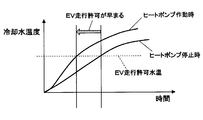
図2はヒートポンプの作動時及び停止時における冷却水温度の挙動を示すタイムチャートである。
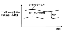
図3はヒートポンプの作動時及び停止時におけるエンジンから冷却水に伝熱される熱量の挙動を示すタイムチャートである。
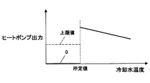
図4は実施例におけるヒートポンプの作動制限を説明する図である。
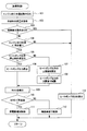
図5は実施例における加熱制御ルーチンの処理の流れを示すフローチャートである。
The above and other objects, features and advantages of the present disclosure will become more apparent from the following detailed description with reference to the accompanying drawings. The drawing
FIG. 1 is a diagram showing a schematic configuration of a control system for a hybrid vehicle in the embodiment. FIG. 2 is a time chart showing the behavior of the cooling water temperature when the heat pump is activated and stopped. FIG. 3 is a time chart showing the behavior of the amount of heat transferred from the engine to the cooling water when the heat pump is activated and stopped. FIG. 4 is a diagram for explaining the operation restriction of the heat pump in the embodiment. FIG. 5 is a flowchart showing the flow of processing of the heating control routine in the embodiment.
以下、実施例を説明する。まず、図1に基づいてハイブリッド車の制御システムの概略構成を説明する。車両の動力源として内燃機関であるエンジン11とモータジェネレータ(以下「MG」と表記する)12とが搭載されている。エンジン11の出力軸(つまりクランク軸)の動力がMG12を介して変速機13に伝達される。この変速機13の出力軸の動力がデファレンシャルギヤ機構14や車軸15等を介して車輪16(つまり駆動輪)に伝達される。変速機13は、複数段の変速段の中から変速段を段階的に切り換える有段変速機であっても良いし、無段階に変速する無段変速機(いわゆるCVT)であっても良い。
Hereinafter, examples will be described. First, a schematic configuration of a hybrid vehicle control system will be described with reference to FIG. An engine 11 that is an internal combustion engine and a motor generator (hereinafter referred to as “MG”) 12 are mounted as power sources for the vehicle. The power of the output shaft (that is, crankshaft) of the engine 11 is transmitted to the transmission 13 via the MG 12. The power of the output shaft of the transmission 13 is transmitted to the wheels 16 (that is, drive wheels) via the differential gear mechanism 14 and the axle 15 or the like. The transmission 13 may be a stepped transmission that switches the speed step among a plurality of speed steps, or may be a continuously variable transmission (so-called CVT) that changes continuously.
エンジン11の動力を車輪16に伝達する動力伝達経路のうちのエンジン11と変速機13との間に、MG12の回転軸が動力伝達可能に連結されている。尚、エンジン11とMG12との間(又はMG12と変速機13との間)に、動力伝達を断続するためのクラッチを設けるようにしても良い。
Rotational shaft of the MG 12 is connected between the engine 11 and the transmission 13 in the power transmission path for transmitting the power of the engine 11 to the wheels 16 so that the power can be transmitted. A clutch for intermittently transmitting power may be provided between the engine 11 and the MG 12 (or between the MG 12 and the transmission 13).
エンジン11の動力で駆動される発電機17の発電電力が高圧バッテリ18に充電される。また、MG12を駆動するインバータ19が高圧バッテリ18に接続され、MG12がインバータ19を介して高圧バッテリ18と電力を授受する。発電機17には、DC-DCコンバータ20を介して低圧バッテリ21が接続されている。
The generated power of the generator 17 driven by the power of the engine 11 is charged in the high voltage battery 18. An inverter 19 that drives the MG 12 is connected to the high voltage battery 18, and the MG 12 exchanges power with the high voltage battery 18 through the inverter 19. A low voltage battery 21 is connected to the generator 17 via a DC-DC converter 20.
高圧バッテリ18と低圧バッテリ21は、いずれも充放電可能なバッテリであり、高圧バッテリ18と低圧バッテリ21との間に、DC-DCコンバータ20が接続されている。更に、DC-DCコンバータ20には、高圧バッテリ18からDC-DCコンバータ20を介して供給される電力又は低圧バッテリ21から供給される電力を消費する低圧負荷が接続されている。
Both the high voltage battery 18 and the low voltage battery 21 are chargeable / dischargeable batteries, and a DC-DC converter 20 is connected between the high voltage battery 18 and the low voltage battery 21. Further, the DC-DC converter 20 is connected to a low-voltage load that consumes electric power supplied from the high-voltage battery 18 via the DC-DC converter 20 or electric power supplied from the low-voltage battery 21.
また、車室内を暖房するための暖房装置として、エンジン11の冷却水の熱を利用する温水暖房装置22が搭載されている。この温水暖房装置22は、エンジン11の冷却水通路(いわゆるウォータジャケット)に、暖房用の冷却水回路23が接続されている。この冷却水回路23には、電動ウォータポンプ24と暖房用のヒータコア25が設けられている。更に、冷却水回路23には、冷却水を加熱するヒートポンプ26の加熱器28が設けられている。
Also, a hot water heater 22 that uses the heat of the cooling water of the engine 11 is mounted as a heating device for heating the vehicle interior. In the hot water heater 22, a cooling water circuit 23 for heating is connected to a cooling water passage (so-called water jacket) of the engine 11. The cooling water circuit 23 is provided with an electric water pump 24 and a heater core 25 for heating. Further, the cooling water circuit 23 is provided with a heater 28 of a heat pump 26 that heats the cooling water.
電動ウォータポンプ24は、低圧バッテリ21の電力で駆動され、この電動ウォータポンプ24によりエンジン11と加熱器28とヒータコア25との間で冷却水を循環させるようになっている。加熱器28は、ヒートポンプ26の熱交換器であり、冷媒と冷却水との間で熱交換して冷却水を加熱する。ヒータコア25は、冷却水と空気との間で熱交換して空気を加熱する。
The electric water pump 24 is driven by the electric power of the low-voltage battery 21, and the electric water pump 24 circulates cooling water among the engine 11, the heater 28, and the heater core 25. The heater 28 is a heat exchanger of the heat pump 26, and heats the cooling water by exchanging heat between the refrigerant and the cooling water. The heater core 25 heats the air by exchanging heat between the cooling water and the air.
ヒートポンプ26は、電動コンプレッサ27で低温低圧のガス冷媒を圧縮して高温高圧のガス冷媒にした後、加熱器28で高温高圧のガス冷媒から熱を放出させて高圧の液状冷媒にする。この後、膨張弁29で高圧の液状冷媒を減圧膨張させて低温低圧の液状冷媒にした後、室外熱交換器30で低温低圧の液状冷媒に熱を吸収させて低温低圧のガス冷媒にする。このヒートポンプ26が「加熱装置」に相当する。
The heat pump 26 compresses the low-temperature and low-pressure gas refrigerant into the high-temperature and high-pressure gas refrigerant with the electric compressor 27, and then releases the heat from the high-temperature and high-pressure gas refrigerant into the high-pressure liquid refrigerant with the heater 28. Thereafter, the high-pressure liquid refrigerant is decompressed and expanded by the expansion valve 29 to form a low-temperature and low-pressure liquid refrigerant, and the outdoor heat exchanger 30 absorbs heat into the low-temperature and low-pressure liquid refrigerant to form a low-temperature and low-pressure gas refrigerant. The heat pump 26 corresponds to a “heating device”.
冷却水回路23には、エンジン11から流出する冷却水の温度であるエンジン出口水温を検出する出口水温センサ31が設けられている。ヒータコア25の近傍には、温風を発生させるブロアファン32が配置されている。
The cooling water circuit 23 is provided with an outlet water temperature sensor 31 that detects an engine outlet water temperature that is the temperature of the cooling water flowing out from the engine 11. A blower fan 32 that generates warm air is disposed in the vicinity of the heater core 25.
また、アクセルセンサ34によってアクセル開度(つまりアクセルペダルの操作量)が検出される。シフトスイッチ35によってシフトレバーの操作位置が検出される。ブレーキスイッチ36によってブレーキ操作(又はブレーキセンサによってブレーキ操作量)が検出される。車速センサ37によって車速が検出される。加速度センサ38によって加速度が検出される。
Further, the accelerator opening (that is, the operation amount of the accelerator pedal) is detected by the accelerator sensor 34. An operating position of the shift lever is detected by the shift switch 35. A brake operation (or a brake operation amount by a brake sensor) is detected by the brake switch 36. The vehicle speed is detected by the vehicle speed sensor 37. The acceleration sensor 38 detects acceleration.
ハイブリッドECU39は、車両全体を総合的に制御する制御装置であり、上述した各種のセンサやスイッチの出力信号を読み込んで、車両の運転状態を検出する。このハイブリッドECU39は、エンジンECU40とMG-ECU41とエアコンECU42との間で制御信号やデータ信号等を送受信する。
The hybrid ECU 39 is a control device that comprehensively controls the entire vehicle, and detects the driving state of the vehicle by reading the output signals of the various sensors and switches described above. The hybrid ECU 39 transmits and receives control signals, data signals, and the like among the engine ECU 40, the MG-ECU 41, and the air conditioner ECU.
エンジンECU40は、エンジン11の運転を制御する制御装置である。MG-ECU41は、インバータ19を制御してMG12を制御すると共に発電機17やDC-DCコンバータ20を制御する制御装置である。エアコンECU42は、温水暖房装置22(例えば電動ウォータポンプ24、電動コンプレッサ27、ブロアファン32等)を制御する制御装置である。
The engine ECU 40 is a control device that controls the operation of the engine 11. The MG-ECU 41 is a control device that controls the generator 19 and the DC-DC converter 20 while controlling the MG 12 by controlling the inverter 19. The air conditioner ECU 42 is a control device that controls the hot water heater 22 (for example, the electric water pump 24, the electric compressor 27, the blower fan 32, etc.).
ハイブリッドECU39は、各ECU40~42によって車両の運転状態に応じて、エンジン11、MG12、発電機17、DC-DCコンバータ20、温水暖房装置22等を制御する。更に、ハイブリッドECU39は、高圧バッテリ18を監視する電源ECU43との間でも制御信号やデータ信号等を送受信する。
The hybrid ECU 39 controls the engine 11, the MG 12, the generator 17, the DC-DC converter 20, the hot water heater 22 and the like by the ECUs 40 to 42 according to the driving state of the vehicle. Further, the hybrid ECU 39 transmits and receives control signals and data signals to and from the power supply ECU 43 that monitors the high voltage battery 18.
その際、ハイブリッドECU39は、走行モードを、例えば、エンジン走行モードとアシスト走行モードとEV走行モードとの間で切り換える。エンジン走行モードでは、エンジン11の動力のみで車輪16を駆動して車両を走行させるエンジン走行を行う。アシスト走行モードでは、エンジン11の動力とMG12の動力の両方で車輪16を駆動して車両を走行させるアシスト走行を行う。EV走行モードでは、MG12の動力のみで車輪16を駆動して車両を走行させるEV走行を行う。
At that time, the hybrid ECU 39 switches the travel mode between, for example, an engine travel mode, an assist travel mode, and an EV travel mode. In the engine running mode, engine running is performed in which the vehicle 16 is driven by driving the wheels 16 only with the power of the engine 11. In the assist travel mode, assist travel is performed in which the vehicle 16 travels by driving the wheels 16 with both the power of the engine 11 and the power of the MG 12. In the EV travel mode, EV travel is performed in which the vehicle 16 travels by driving the wheels 16 only with the power of the MG 12.
また、ハイブリッドECU39は、車両を制動する際(例えばアクセルオフ時やブレーキオン時に制動力を発生させる際)に、走行モードを回生発電モードに切り換える。この回生発電モードでは、車輪16の動力でMG12を駆動することで、車両の運動エネルギをMG12で電気エネルギに変換する回生発電を行い、その発電電力である回生電力を高圧バッテリ18に充電する。これにより、アシスト走行やEV走行の実施可能時間を長くして燃費を向上させることができる。
The hybrid ECU 39 switches the traveling mode to the regenerative power generation mode when braking the vehicle (for example, when generating a braking force when the accelerator is off or the brake is on). In this regenerative power generation mode, the MG 12 is driven by the power of the wheels 16 to perform regenerative power generation by converting the kinetic energy of the vehicle into electrical energy by the MG 12, and the regenerative power that is the generated power is charged in the high-voltage battery 18. Thereby, the feasible time of assist driving | running | working and EV driving | running can be lengthened, and a fuel consumption can be improved.
ところで、ヒートポンプ26でエンジン11の冷却水を温めると、エンジン入口水温(つまりエンジン11へ流入する冷却水の温度)が上昇し、エンジン11の廃熱のうち冷却水に伝熱される熱量が減少して、大気へ放熱される熱量が増加する。この理由は、エンジン本体温度とエンジン入口水温との温度差が小さくなり、エンジン11から冷却水に伝熱される熱量は温度差に比例するためである。ヒートポンプ26を使うと、図2に示すように、冷却水の温度の上昇は早くなるが、図3に示すように、エンジン11から冷却水に伝熱される熱量が減少して、エンジン11から大気へ放熱される熱量が増加する。その分、無駄になる熱量が増加して、ヒートポンプ26が余分に仕事をしなければならず、ヒートポンプ26の消費電力が増加して燃料消費量が増加する。
By the way, when the cooling water of the engine 11 is warmed by the heat pump 26, the engine inlet water temperature (that is, the temperature of the cooling water flowing into the engine 11) rises, and the amount of heat transferred to the cooling water among the waste heat of the engine 11 decreases. This increases the amount of heat released to the atmosphere. This is because the temperature difference between the engine body temperature and the engine inlet water temperature is small, and the amount of heat transferred from the engine 11 to the cooling water is proportional to the temperature difference. When the heat pump 26 is used, the temperature of the cooling water rises faster as shown in FIG. 2, but the amount of heat transferred from the engine 11 to the cooling water decreases as shown in FIG. The amount of heat released to Accordingly, the amount of heat that is wasted increases and the heat pump 26 has to do extra work. The power consumption of the heat pump 26 increases and the fuel consumption increases.
燃費効果は、冷却水を早く温めたことによる燃料減少分と、その昇温のために使った燃料増加分との差分で決まる。昇温のためにより多くの燃料を使うと燃費効果は無くなる。低温からヒートポンプ26を使うと、燃料増加分が燃料減少分よりも大きくなって、燃費が悪化する可能性がある。尚、図2に示すように、冷却水早期昇温による主要な燃費改善は、EV走行の許可が早まることによるものであり、エンジン本体の暖機効果による摩擦損失の減少は少ない。
The fuel efficiency effect is determined by the difference between the fuel decrease due to the early warming of the cooling water and the fuel increase used for the temperature increase. If more fuel is used to raise the temperature, the fuel efficiency will be lost. If the heat pump 26 is used from a low temperature, the fuel increase amount becomes larger than the fuel decrease amount, and the fuel consumption may be deteriorated. As shown in FIG. 2, the main improvement in fuel consumption due to the early rise in cooling water temperature is due to the earlier permission for EV travel, and the reduction in friction loss due to the warm-up effect of the engine body is small.
そこで、本実施例では、ハイブリッドECU39により後述する図5の加熱制御ルーチンを実行することで、次のような制御を行う。例えば、図4に示すように、冷却水の温度が所定値(例えばエンジン停止可能な暖機完了水温)よりも低いか否かを判定し、冷却水の温度が所定値よりも低いと判定された場合に、ヒートポンプ26の出力を停止又は所定の上限値以下に制限する作動制限を行う。これにより、ヒートポンプ26の作動制限を行わない場合に比べて、ヒートポンプ26による冷却水温度上昇を抑制して、エンジン11から冷却水に伝熱される熱量を増加させて、エンジン11から大気へ放熱される熱量を減少させる。その分、無駄になる熱量を減少させて、燃費を向上させる。
Therefore, in the present embodiment, the following control is performed by executing a heating control routine of FIG. For example, as shown in FIG. 4, it is determined whether or not the temperature of the cooling water is lower than a predetermined value (for example, a warm-up completion water temperature at which the engine can be stopped), and it is determined that the temperature of the cooling water is lower than the predetermined value. In such a case, the output of the heat pump 26 is stopped or the operation is limited to limit the output to a predetermined upper limit value or less. As a result, compared with the case where the operation restriction of the heat pump 26 is not performed, an increase in the cooling water temperature by the heat pump 26 is suppressed, the amount of heat transferred from the engine 11 to the cooling water is increased, and the heat is radiated from the engine 11 to the atmosphere. Reduce the amount of heat generated. The amount of wasted heat is reduced accordingly, and fuel efficiency is improved.
ここで、エンジン11から大気への放熱性(例えば放熱し易さの度合)が高い場合(例えばエンジンルーム内への通風量が多い場合)には、ヒートポンプ26で冷却水の温度を上昇させると、エンジン11から大気へ放熱される熱量(つまり無駄になる熱量)が大きく増加する可能性がある。一方、エンジン11から大気への放熱性が低い場合には、ヒートポンプ26で冷却水の温度を上昇させても、エンジン11から大気へ放熱される熱量(つまり無駄になる熱量)は放熱性が高い場合ほどは増加しない。
Here, when the heat dissipation from the engine 11 to the atmosphere (for example, the degree of ease of heat dissipation) is high (for example, when there is a large amount of ventilation into the engine room), the temperature of the cooling water is increased by the heat pump 26. There is a possibility that the amount of heat radiated from the engine 11 to the atmosphere (that is, the amount of wasted heat) is greatly increased. On the other hand, when the heat dissipation from the engine 11 to the atmosphere is low, even if the temperature of the cooling water is increased by the heat pump 26, the amount of heat radiated from the engine 11 to the atmosphere (that is, the amount of wasted heat) is high. Does not increase as much as the case.
このような特性を考慮して、本実施例では、エンジン11から大気への放熱性を判定し、ヒートポンプ26の作動制限を行う際に、エンジン11から大気への放熱性の判定結果に応じてヒートポンプ26の出力を停止するか上限値以下に制限するかを決定する。
In consideration of such characteristics, in this embodiment, the heat dissipation from the engine 11 to the atmosphere is determined, and when the operation restriction of the heat pump 26 is performed, according to the determination result of the heat dissipation from the engine 11 to the atmosphere. It is determined whether to stop the output of the heat pump 26 or to limit it to an upper limit value or less.
具体的には、エンジン11から大気への放熱性が高いと判定された場合には、ヒートポンプ26で冷却水の温度を上昇させると、エンジン11から大気へ放熱される熱量が大きく増加する可能性があると判断して、ヒートポンプ26の出力を停止する。一方、エンジン11から大気への放熱性が高くないと判定された場合には、ヒートポンプ26で冷却水の温度を上昇させても、エンジン11から大気へ放熱される熱量は放熱性が高い場合ほどは増加しないと判断して、ヒートポンプ26の出力を上限値以下に制限する。
Specifically, when it is determined that the heat dissipation from the engine 11 to the atmosphere is high, if the temperature of the cooling water is increased by the heat pump 26, the amount of heat radiated from the engine 11 to the atmosphere may greatly increase. The output of the heat pump 26 is stopped. On the other hand, if it is determined that the heat dissipation from the engine 11 to the atmosphere is not high, even if the temperature of the cooling water is increased by the heat pump 26, the amount of heat radiated from the engine 11 to the atmosphere increases as the heat dissipation increases. Therefore, the output of the heat pump 26 is limited to the upper limit value or less.
次に、低温時にヒートポンプ26の作動制限を行うにも拘らずヒートポンプ26が必要な理由を説明する。冷却水の温度が所定値よりも低い低温時から所定値(例えばエンジン停止可能な暖機完了水温)に上昇するまでは、ヒートポンプ26の作動制限を行うべきであるが、それ以降はヒートポンプ26を活用した方が燃費が向上する。燃費向上の原資はEV走行時間の延長である。暖機完了水温以上で燃費が向上する理由は、ヒートポンプ26の熱をエンジン11の暖機ではなく車室内空気の暖房に使うためである。ヒートポンプ26で生成した熱を全て暖房に使えばエンジン入口水温は上昇しない。そのため、ヒートポンプ26を使ってもエンジン11の廃熱は変化しない。ヒートポンプ26を使わないと、エンジン11だけで暖房熱を賄う必要があり、それではエンジン11を停止できない。つまり、EV走行を行うことができず、燃費が悪くなる。従って、低温時(つまり暖機時)にヒートポンプ26を停止しても、ヒートポンプ26を暖房で使って燃費を向上させるためにヒートポンプ26は必要である。
Next, the reason why the heat pump 26 is necessary even though the operation of the heat pump 26 is limited at low temperatures will be described. The operation of the heat pump 26 should be limited until the temperature of the cooling water rises from a low temperature lower than a predetermined value to a predetermined value (for example, a warm-up completion water temperature at which the engine can be stopped). Utilization improves fuel efficiency. The source of fuel efficiency improvement is the extension of EV travel time. The reason why the fuel efficiency is improved above the warm-up water temperature is that the heat of the heat pump 26 is used not for warming up the engine 11 but for heating the vehicle interior air. If all the heat generated by the heat pump 26 is used for heating, the engine inlet water temperature does not rise. Therefore, even if the heat pump 26 is used, the waste heat of the engine 11 does not change. If the heat pump 26 is not used, it is necessary to cover the heating heat only with the engine 11, and the engine 11 cannot be stopped. That is, EV traveling cannot be performed, and fuel consumption is deteriorated. Therefore, even if the heat pump 26 is stopped at a low temperature (that is, during warm-up), the heat pump 26 is necessary to improve the fuel consumption by using the heat pump 26 for heating.
以下、本実施例でハイブリッドECU39が実行する図5の加熱制御ルーチンの処理内容を説明する。図5に示す加熱制御ルーチンは、ハイブリッドECU39の電源オン期間中に所定周期で繰り返し実行され、「加熱制御部」としての役割を果たす。
Hereinafter, the processing content of the heating control routine of FIG. 5 executed by the hybrid ECU 39 in this embodiment will be described. The heating control routine shown in FIG. 5 is repeatedly executed at a predetermined cycle during the power-on period of the hybrid ECU 39, and serves as a “heating control unit”.
本ルーチンが起動されると、まず、ステップ101で、出口水温センサ31で検出したエンジン出口水温を読み込む。この後、ステップ102に進み、電動ウォータポンプ24の回転速度に応じて、冷却水回路23を流れる冷却水の流量をマップ又は数式等により算出する。冷却水の流量のマップ又は数式等は、電動ウォータポンプ24の回転速度が高いほど冷却水の流量が多くなるように設定されている。
When this routine is started, first, in step 101, the engine outlet water temperature detected by the outlet water temperature sensor 31 is read. Thereafter, the process proceeds to step 102, and the flow rate of the cooling water flowing through the cooling water circuit 23 is calculated by a map or a mathematical formula according to the rotational speed of the electric water pump 24. The flow map or formula of the flow rate of the cooling water is set so that the flow rate of the coolant increases as the rotational speed of the electric water pump 24 increases.
この後、ステップ103に進み、暖房優先指示があるか否かを判定する。この暖房優先指示は、燃費優先ではなく快適性優先の指示である。この場合、例えば、ユーザーが操作可能な暖房優先スイッチが押された状態であるか否かによって、暖房優先指示があるか否かを判定する。或は、燃費優先指示スイッチ(例えばエコスイッチ)が解除された状態であるか否かによって、暖房優先指示があるか否かを判定するようにしても良い。このステップ103の処理が「暖房優先判定部」としての役割を果たす。
Thereafter, the process proceeds to step 103 to determine whether or not there is a heating priority instruction. This heating priority instruction is not a fuel efficiency priority but a comfort priority instruction. In this case, for example, whether or not there is a heating priority instruction is determined based on whether or not the heating priority switch operable by the user has been pressed. Or you may make it determine whether there exists a heating priority instruction | indication by whether it is in the state by which the fuel consumption priority instruction | indication switch (for example, eco switch) was cancelled | released. The process of step 103 serves as a “heating priority determination unit”.
このステップ103で、暖房優先指示があると判定された場合には、ステップ113に進む。このステップ113で、冷却水の温度と流量に応じてヒートポンプ26の出力を算出する。具体的には、目標暖房水温[K] とエンジン出口水温[K] と冷却水の流量[kg/s]と比熱[kJ/kg/K] とを用いてヒートポンプ26の出力[kW]を下記(1)式により算出する。
ヒートポンプ出力=(目標暖房水温-エンジン出口水温)×流量×比熱 …(1) If it is determined instep 103 that there is a heating priority instruction, the process proceeds to step 113. In step 113, the output of the heat pump 26 is calculated according to the temperature and flow rate of the cooling water. Specifically, using the target heating water temperature [K], engine outlet water temperature [K], cooling water flow rate [kg / s] and specific heat [kJ / kg / K], the output [kW] of the heat pump 26 is Calculated by equation (1).
Heat pump output = (target heating water temperature-engine outlet water temperature) x flow rate x specific heat (1)
ヒートポンプ出力=(目標暖房水温-エンジン出口水温)×流量×比熱 …(1) If it is determined in
Heat pump output = (target heating water temperature-engine outlet water temperature) x flow rate x specific heat (1)
これに対して、上記ステップ103で、暖房優先指示がないと判定された場合には、ステップ104に進む。このステップ104で、エンジン出口水温が所定値よりも低いか否かを判定する。ここで、所定値は、例えば、エンジン停止可能な暖機完了水温(例えば40℃)に設定されている。エンジン出口水温が所定値以上に上昇すると、エンジン11を停止してMG12の動力で走行するEV走行が許可される。このステップ104の処理が「水温判定部」としての役割を果たす。
In contrast, if it is determined in step 103 that there is no heating priority instruction, the process proceeds to step 104. In step 104, it is determined whether the engine outlet water temperature is lower than a predetermined value. Here, for example, the predetermined value is set to a warm-up completion water temperature (for example, 40 ° C.) at which the engine can be stopped. When the engine outlet water temperature rises to a predetermined value or higher, EV running is permitted in which the engine 11 is stopped and the MG 12 is driven. The processing in step 104 serves as a “water temperature determination unit”.
このステップ104で、エンジン出口水温が所定値よりも低いと判定された場合には、ヒートポンプ26の作動制限を次のようにして行う。まず、ステップ105で、ヒートポンプ26の出力停止条件が成立しているか否かを、例えば、次の(1) ~(3) の条件によって判定する。
If it is determined in step 104 that the engine outlet water temperature is lower than the predetermined value, the operation restriction of the heat pump 26 is performed as follows. First, in step 105, whether or not the output stop condition of the heat pump 26 is satisfied is determined based on, for example, the following conditions (1) to (3).
(1) エンジンルームへの通風量を調節するグリルシャッタ又はラジエタヘの通風量を調節するラジエタシャッタが閉じている(例えば全開位置よりも閉じ側である)こと(2) エンジンルーム内の雰囲気温度が所定値(例えばエンジン出口水温に応じて設定した値)よりも高いこと(3) エンジン本体を流れる冷却水の流量が所定値(例えば予め設定した固定値)以下であること
(1) The grille shutter that adjusts the airflow to the engine room or the radiator shutter that adjusts the airflow to the radiator is closed (for example, close to the fully open position). (2) The ambient temperature in the engine room is It is higher than a predetermined value (for example, a value set according to the engine outlet water temperature). (3) The flow rate of cooling water flowing through the engine body is not more than a predetermined value (for example, a preset fixed value).
これらの(1) ~(3) の条件は、エンジン11から大気への放熱性(例えば放熱し易さの度合)が高いか否かを判定するための条件である。上記(1) ~(3) の条件を全て満たさない場合には、エンジン11から大気への放熱性が高いと判定して、ヒートポンプ26の出力停止条件が成立していると判定する。一方、上記(1) ~(3) の条件のうちのいずれか一つでも満たす場合には、エンジン11から大気への放熱性が高くない(つまり低い)と判定して、ヒートポンプ26の出力停止条件が不成立と判定する。このステップ105の処理が「放熱判定部」としての役割を果たす。
These conditions (1) to (3) are conditions for determining whether or not the heat dissipation from the engine 11 to the atmosphere (for example, the degree of ease of heat dissipation) is high. If all of the above conditions (1) to (3) are not satisfied, it is determined that the heat dissipation from the engine 11 to the atmosphere is high, and it is determined that the output stop condition of the heat pump 26 is satisfied. On the other hand, if any one of the above conditions (1) to (3) is satisfied, it is determined that the heat dissipation from the engine 11 to the atmosphere is not high (that is, low), and the output of the heat pump 26 is stopped. It is determined that the condition is not satisfied. The process of step 105 serves as a “heat dissipation determination unit”.
尚、シートヒータやカーボンヒータ等の直接又は輻射熱で人体を温める補助ヒータを備えている場合には、次の(4) の条件を加えるようにしても良い。(4) 補助ヒータの出力が所定値(例えば外気温に応じて設定した値)よりも低いこと
この場合、上記(1) ~(4) の条件を全て満たさない場合には、ヒートポンプ26の出力停止条件が成立していると判定する。一方、上記(1) ~(4) の条件のうちのいずれか一つでも満たす場合には、ヒートポンプ26の出力停止条件が不成立と判定する。 When an auxiliary heater that warms the human body directly or by radiant heat, such as a seat heater or a carbon heater, is provided, the following condition (4) may be added. (4) The output of the auxiliary heater is lower than a predetermined value (for example, a value set according to the outside temperature). In this case, if all of the above conditions (1) to (4) are not satisfied, the output of theheat pump 26 It is determined that the stop condition is satisfied. On the other hand, when any one of the above conditions (1) to (4) is satisfied, it is determined that the output stop condition of the heat pump 26 is not satisfied.
この場合、上記(1) ~(4) の条件を全て満たさない場合には、ヒートポンプ26の出力停止条件が成立していると判定する。一方、上記(1) ~(4) の条件のうちのいずれか一つでも満たす場合には、ヒートポンプ26の出力停止条件が不成立と判定する。 When an auxiliary heater that warms the human body directly or by radiant heat, such as a seat heater or a carbon heater, is provided, the following condition (4) may be added. (4) The output of the auxiliary heater is lower than a predetermined value (for example, a value set according to the outside temperature). In this case, if all of the above conditions (1) to (4) are not satisfied, the output of the
このステップ105で、ヒートポンプ26の出力停止条件が成立していると判定された場合には、ステップ106に進む。このステップ106で、ヒートポンプ26の出力を停止した状態に維持する。
If it is determined in step 105 that the output stop condition of the heat pump 26 is satisfied, the process proceeds to step 106. In step 106, the output of the heat pump 26 is maintained in a stopped state.
一方、上記ステップ105で、ヒートポンプ26の出力停止条件が不成立と判定された場合には、ステップ107に進む。このステップ107で、ヒートポンプ26の出力の上限値を次のようにして設定する。
On the other hand, if it is determined in step 105 that the output stop condition of the heat pump 26 is not satisfied, the process proceeds to step 107. In step 107, the upper limit value of the output of the heat pump 26 is set as follows.
上記(1) の条件を満たす場合には、グリルシャッタ又はラジエタシャッタの開度に応じて上限値をマップ又は数式等により設定(つまり算出)する。この場合、上限値のマップ又は数式等は、開度が小さいほど上限値が高くなるように設定されている。
If the above condition (1) 条件 を 満 た す is satisfied, the upper limit value is set (that is, calculated) according to the opening degree of the grill shutter or radiator shutter using a map or a mathematical expression. In this case, the upper limit map or formula is set such that the lower the opening, the higher the upper limit.
上記(2) の条件を満たす場合には、エンジンルーム内の雰囲気温度に応じて上限値をマップ又は数式等により設定(つまり算出)する。この場合、上限値のマップ又は数式等は、雰囲気温度が高いほど上限値が高くなるように設定されている。
If the above condition (2) is satisfied, the upper limit value is set (that is, calculated) according to the ambient temperature in the engine room using a map or formula. In this case, the upper limit map or formula is set such that the higher the ambient temperature, the higher the upper limit value.
上記(3) の条件を満たす場合には、冷却水の流量に応じて上限値をマップ又は数式等により設定(つまり算出)する。この場合、上限値のマップ又は数式等は、冷却水の流量が少ないほど上限値が高くなるように設定されている。
If the above condition (3) IV is satisfied, the upper limit value is set (that is, calculated) according to the flow rate of the cooling water using a map or a mathematical expression. In this case, the upper limit map or formula is set such that the lower the coolant flow rate, the higher the upper limit value.
上記(4) の条件を満たす場合には、補助ヒータの出力に応じて上限値をマップ又は数式等により設定(つまり算出)する。この場合、上限値のマップ又は数式等は、補助ヒータの出力が低いほど上限値が高くなるように設定されている。
When the above condition (4) IV is satisfied, the upper limit value is set (that is, calculated) according to the output of the auxiliary heater using a map or mathematical formula. In this case, the upper limit map or numerical formula is set such that the lower the output of the auxiliary heater, the higher the upper limit value.
この後、ステップ108に進み、上記(1)式を用いてヒートポンプ26の出力を算出し、そのヒートポンプ26の出力を上限値以下に制限する。具体的には、上記(1)式を用いて算出したヒートポンプ26の出力が上限値以下の場合には、そのヒートポンプ26の出力をそのまま採用する。これに対して、上記(1)式を用いて算出したヒートポンプ26の出力が上限値よりも高い場合には、ヒートポンプ26の出力を上限値に設定する。
Thereafter, the process proceeds to step 108, where the output of the heat pump 26 is calculated using the above equation (1), and the output of the heat pump 26 is limited to the upper limit value or less. Specifically, when the output of the heat pump 26 calculated using the above equation (1) is equal to or lower than the upper limit value, the output of the heat pump 26 is employed as it is. On the other hand, when the output of the heat pump 26 calculated using the above equation (1) is higher than the upper limit value, the output of the heat pump 26 is set to the upper limit value.
以上のようにして、ヒートポンプ26の作動制限を開始した後、ステップ109に進み、高圧バッテリ18の残容量を表すSOCを検出する。SOCは、例えば、次式により定義される。
SOC=残容量/満充電容量×100 After starting the operation restriction of theheat pump 26 as described above, the routine proceeds to step 109, where the SOC representing the remaining capacity of the high voltage battery 18 is detected. The SOC is defined by the following equation, for example.
SOC = remaining capacity / full charge capacity × 100
SOC=残容量/満充電容量×100 After starting the operation restriction of the
SOC = remaining capacity / full charge capacity × 100
この後、ステップ110に進み、高圧バッテリ18のSOCが所定値よりも低いか否かを判定する。この所定値は、SOCの許容下限値と許容上限値の中間の値(例えばSOCの許容下限値よりも少し高い値)に設定されている。
Thereafter, the process proceeds to step 110, and it is determined whether or not the SOC of the high voltage battery 18 is lower than a predetermined value. This predetermined value is set to an intermediate value between the allowable lower limit value of SOC and the allowable upper limit value (for example, a value slightly higher than the allowable lower limit value of SOC).
このステップ110で、高圧バッテリ18のSOCが所定値よりも低いと判定された場合には、ステップ111に進む。このステップ111で、発電量増加制御を実行する。この発電量増加制御では、エンジン11の出力を増加させてエンジン11の動力で駆動される発電機17の発電量を増加させると共にエンジン11の廃熱生成量を増加させる。このステップ111の処理が「発電量増加制御部」としての役割を果たす。
If it is determined in step 110 that the SOC of the high voltage battery 18 is lower than the predetermined value, the process proceeds to step 111. In step 111, power generation amount increase control is executed. In this power generation amount increase control, the output of the engine 11 is increased to increase the power generation amount of the generator 17 driven by the power of the engine 11 and the waste heat generation amount of the engine 11 is increased. The processing in step 111 serves as a “power generation increase control unit”.
一方、上記ステップ110で、高圧バッテリ18のSOCが所定値以上と判定された場合には、ステップ112に進む。このステップ112で、軸効率低下制御を実行する。この軸効率低下制御では、エンジン11の消費燃料量に対する軸出力の割合である軸効率を低下させてエンジン11の消費燃料量に対する廃熱生成量の割合である廃熱生成効率を上昇させる(つまり冷却損失を大きくする)。この場合、例えば、エンジン11の出力を変えずに回転速度を上昇させたり、或は、点火時期を遅角させたりすることで、軸効率を低下させる。このステップ112の処理が「軸効率低下制御部」としての役割を果たす。
On the other hand, if it is determined in step 110 that the SOC of the high voltage battery 18 is equal to or greater than the predetermined value, the process proceeds to step 112. In this step 112, shaft efficiency reduction control is executed. In this shaft efficiency reduction control, the shaft efficiency, which is the ratio of the shaft output to the fuel consumption of the engine 11, is reduced to increase the waste heat generation efficiency, which is the ratio of the waste heat generation to the fuel consumption of the engine 11 (that is, Increase cooling loss). In this case, for example, the shaft efficiency is lowered by increasing the rotational speed without changing the output of the engine 11 or retarding the ignition timing. The processing in step 112 serves as an “axial efficiency reduction control unit”.
ヒートポンプ26の作動制限を開始した後、上記ステップ103で、暖房優先指示があると判定された場合には、ヒートポンプ26の作動制限を解除すると共に、発電量増加制御や軸効率低下制御を終了する。この場合、ステップ113に進み、上記(1)式を用いてヒートポンプ26の出力を算出する。
After starting the operation restriction of the heat pump 26, when it is determined in step 103 that there is a heating priority instruction, the operation restriction of the heat pump 26 is released, and the power generation amount increase control and the shaft efficiency decrease control are ended. . In this case, the process proceeds to step 113, and the output of the heat pump 26 is calculated using the above equation (1).
また、ヒートポンプ26の作動制限を開始した後、上記ステップ104で、エンジン出口水温が所定値以上と判定された場合には、ヒートポンプ26の作動制限を解除すると共に、発電量増加制御や軸効率低下制御を終了する。この場合、ステップ113に進み、上記(1)式を用いてヒートポンプ26の出力を算出する。
In addition, after starting the operation restriction of the heat pump 26, when it is determined in step 104 that the engine outlet water temperature is equal to or higher than a predetermined value, the operation restriction of the heat pump 26 is canceled, and the power generation amount increase control and the shaft efficiency decrease. End control. In this case, the process proceeds to step 113, and the output of the heat pump 26 is calculated using the above equation (1).
以上説明した本実施例では、冷却水の温度(例えばエンジン出口水温)が所定値よりも低いと判定された場合に、ヒートポンプ26の出力を停止又は上限値以下に制限する作動制限を行うようにしている。これにより、ヒートポンプ26の作動制限を行わない場合に比べて、ヒートポンプ26による冷却水温度上昇を抑制して、エンジン11から冷却水に伝熱される熱量を増加させて、エンジン11から大気へ放熱される熱量を減少させることができる。その分、無駄になる熱量を減少させることができ、燃費を向上させることができる。
In the present embodiment described above, when it is determined that the temperature of the cooling water (for example, the engine outlet water temperature) is lower than a predetermined value, the output of the heat pump 26 is stopped or the operation is limited to limit the value to the upper limit value or less. ing. As a result, compared with the case where the operation restriction of the heat pump 26 is not performed, an increase in the cooling water temperature by the heat pump 26 is suppressed, the amount of heat transferred from the engine 11 to the cooling water is increased, and the heat is radiated from the engine 11 to the atmosphere. The amount of heat generated can be reduced. Accordingly, the amount of heat that is wasted can be reduced, and fuel consumption can be improved.
また、本実施例では、冷却水の温度が所定値以上と判定された場合に、ヒートポンプ26の作動制限を解除するようにしている。これにより、冷却水の温度が所定値以上の場合には、エンジン11以外の加熱装置であるヒートポンプ26で暖房用の熱量(つまり冷却水の熱量)を確保することが可能となり、エンジン11を停止してMG12の動力で走行するEV走行を行うことができるようになる。
Further, in this embodiment, when the temperature of the cooling water is determined to be equal to or higher than a predetermined value, the operation restriction of the heat pump 26 is released. As a result, when the temperature of the cooling water is equal to or higher than a predetermined value, the heat pump 26 that is a heating device other than the engine 11 can secure the amount of heat for heating (that is, the amount of heat of the cooling water), and the engine 11 is stopped. Thus, it is possible to perform EV traveling that uses the power of MG12.
更に、本実施例では、冷却水の温度が所定値よりも低くても、暖房優先指示があると判定された場合には、ヒートポンプ26の作動制限を解除するようにしている。これにより、暖房優先指示がある場合には、冷却水の温度を速やかに上昇させて、暖房用の熱量(つまり冷却水の熱量)を確保することができ、快適性を向上させることができる。
Furthermore, in this embodiment, even if the temperature of the cooling water is lower than a predetermined value, if it is determined that there is a heating priority instruction, the operation restriction of the heat pump 26 is released. Thereby, when there is a heating priority instruction, the temperature of the cooling water can be quickly raised to ensure the amount of heat for heating (that is, the amount of heat of the cooling water), and comfort can be improved.
また、本実施例では、エンジン11から大気への放熱性を判定し、ヒートポンプ26の作動制限を行う際に、エンジン11から大気への放熱性の判定結果に応じてヒートポンプ26の出力を停止するか上限値以下に制限するかを決定するようにしている。
Further, in this embodiment, when the heat dissipation from the engine 11 to the atmosphere is determined and the operation of the heat pump 26 is restricted, the output of the heat pump 26 is stopped according to the determination result of the heat dissipation from the engine 11 to the atmosphere. Or whether to limit to the upper limit or less.
具体的には、エンジン11から大気への放熱性が高いと判定された場合には、ヒートポンプ26で冷却水の温度を上昇させると、エンジン11から大気へ放熱される熱量が大きく増加する可能性があると判断して、ヒートポンプ26の出力を停止する。これにより、エンジン11から大気へ放熱される熱量(つまり無駄になる熱量)の増加を防止することができる。
Specifically, when it is determined that the heat dissipation from the engine 11 to the atmosphere is high, if the temperature of the cooling water is increased by the heat pump 26, the amount of heat radiated from the engine 11 to the atmosphere may greatly increase. The output of the heat pump 26 is stopped. Thereby, the increase in the amount of heat radiated from the engine 11 to the atmosphere (that is, the amount of wasted heat) can be prevented.
一方、エンジン11から大気への放熱性が高くないと判定された場合には、ヒートポンプ26で冷却水の温度を上昇させても、エンジン11から大気へ放熱される熱量は放熱性が高い場合ほどは増加しないと判断して、ヒートポンプ26の出力を上限値以下に制限する。これにより、エンジン11から大気へ放熱される熱量(つまり無駄になる熱量)の増加を抑制しながら、ヒートポンプ26とエンジン11の両方で冷却水の温度を早く上昇させることができる。
On the other hand, if it is determined that the heat dissipation from the engine 11 to the atmosphere is not high, even if the temperature of the cooling water is increased by the heat pump 26, the amount of heat radiated from the engine 11 to the atmosphere increases as the heat dissipation increases. Therefore, the output of the heat pump 26 is limited to the upper limit value or less. Thereby, the temperature of the cooling water can be quickly raised by both the heat pump 26 and the engine 11 while suppressing an increase in the amount of heat radiated from the engine 11 to the atmosphere (that is, the amount of wasted heat).
また、本実施例では、ヒートポンプ26の作動制限が行われる場合で且つ高圧バッテリ18のSOCが所定値よりも低い場合に、発電量増加制御を実行するようにしている。この発電量増加制御では、エンジン11の出力を増加させてエンジン11の動力で駆動される発電機17の発電量を増加させると共にエンジン11の廃熱生成量を増加させる。これにより、高圧バッテリ18のSOCが低い場合に、発電機17の発電量を増加させて高圧バッテリ18のSOCを上昇させながら、エンジン11の廃熱生成量を増加させて冷却水の温度上昇を早めることができる。
Further, in this embodiment, when the operation restriction of the heat pump 26 is performed and the SOC of the high voltage battery 18 is lower than a predetermined value, the power generation amount increase control is executed. In this power generation amount increase control, the output of the engine 11 is increased to increase the power generation amount of the generator 17 driven by the power of the engine 11 and the waste heat generation amount of the engine 11 is increased. As a result, when the SOC of the high-voltage battery 18 is low, the amount of power generated by the generator 17 is increased and the SOC of the high-voltage battery 18 is increased, while the amount of waste heat generated by the engine 11 is increased and the temperature of the cooling water is increased. You can expedite.
また、本実施例では、ヒートポンプ26の作動制限が行われる場合で且つ高圧バッテリ18のSOCが所定値よりも高い場合に、軸効率低下制御を実行するようにしている。この軸効率低下制御では、エンジン11の軸効率を低下させてエンジン11の廃熱生成効率を上昇させる。これにより、高圧バッテリ18の残容量が高い場合に、エンジン11の出力をあまり変えることなく、エンジン11の軸効率を低下させて廃熱生成効率を上昇させることで、エンジン11の廃熱生成量を増加させて、冷却水の温度上昇を早めることができる。
Further, in this embodiment, the shaft efficiency reduction control is executed when the operation restriction of the heat pump 26 is performed and the SOC of the high voltage battery 18 is higher than a predetermined value. In this shaft efficiency reduction control, the shaft efficiency of the engine 11 is reduced to increase the waste heat generation efficiency of the engine 11. Thereby, when the remaining capacity of the high voltage battery 18 is high, the waste heat generation amount of the engine 11 is increased by reducing the shaft efficiency of the engine 11 and increasing the waste heat generation efficiency without significantly changing the output of the engine 11. To increase the temperature of the cooling water.
尚、発電量増加制御を実行するか否かの判定に用いる所定値と、軸効率低下制御を実行するか否かをの判定に用いる所定値を異なる値に設定ても良い。つまり、ヒートポンプ26の作動制限が行われる場合で且つ高圧バッテリ18のSOCが第一の所定値よりも低い場合に発電量増加制御を実行し、ヒートポンプ26の作動制限が行われる場合で且つ高圧バッテリ18のSOCが第一の所定値よりも高い第二の所定値よりも高い場合に軸効率低下制御を実行するようにしても良い。
Note that the predetermined value used for determining whether to execute the power generation amount increase control and the predetermined value used for determining whether to execute the shaft efficiency reduction control may be set to different values. That is, when the operation restriction of the heat pump 26 is performed and the SOC of the high voltage battery 18 is lower than the first predetermined value, the power generation amount increase control is executed, and the operation restriction of the heat pump 26 is performed and the high voltage battery. The shaft efficiency reduction control may be executed when the SOC of 18 is higher than a second predetermined value higher than the first predetermined value.
また、本実施例では、ヒートポンプ26の作動制限を解除した場合に、上記(1)式を用いてヒートポンプ26の出力を算出することで、冷却水の温度と流量に応じてヒートポンプ26の出力を設定するようにしている。このようにすれば、冷却水の温度や流量に応じて、冷却水の温度を目標水温に制御するのに必要なヒートポンプ26の出力が変化するのに対応して、ヒートポンプ26の出力を変化させてヒートポンプ26の出力を適正値に設定することができる。尚、ヒートポンプ26の作動制限を解除した場合のヒートポンプ26の出力の算出方法は適宜変更しても良い。
Further, in this embodiment, when the operation restriction of the heat pump 26 is released, the output of the heat pump 26 is calculated according to the temperature and flow rate of the cooling water by calculating the output of the heat pump 26 using the above equation (1). I am trying to set it. In this way, the output of the heat pump 26 is changed in response to the change in the output of the heat pump 26 necessary to control the temperature of the cooling water to the target water temperature according to the temperature and flow rate of the cooling water. Thus, the output of the heat pump 26 can be set to an appropriate value. Note that the calculation method of the output of the heat pump 26 when the operation restriction of the heat pump 26 is released may be changed as appropriate.
また、上記実施例では、暖房優先指示があると判定された場合に、ヒートポンプ26の作動制限を解除するようにしているが、これに限定されず、ヒートポンプ26の作動制限を緩和するようにしても良い。例えば、ヒートポンプ26の出力を停止する制御から出力を上限値で制限する制御に変更するようにしても良いし、或は、ヒートポンプ26の出力の上限値を高くするようにしても良い。しかしながら、本開示は、暖房優先指示があると判定された場合に、ヒートポンプ26の作動制限を解除又は緩和する処理を省略するようにしても良い。
In the above embodiment, when it is determined that there is a heating priority instruction, the operation restriction of the heat pump 26 is released. However, the present invention is not limited to this, and the operation restriction of the heat pump 26 is relaxed. Also good. For example, the control for stopping the output of the heat pump 26 may be changed to the control for limiting the output with the upper limit value, or the upper limit value of the output of the heat pump 26 may be increased. However, in the present disclosure, when it is determined that there is a heating priority instruction, the process of releasing or relaxing the operation restriction of the heat pump 26 may be omitted.
また、上記実施例では、上記(1) ~(3) の条件に基づいてエンジン11から大気への放熱性を判定するようにしているが、これに限定されず、エンジン11から大気への放熱性を判定する方法は適宜変更しても良い。例えば、エンジンルーム内の温度を検出するセンサやエンジン本体温度を検出するセンサの出力等に基づいてエンジン11から大気への放熱性を評価する指標(例えば放熱量)を算出するようにしても良い。或は、エンジン11の回転速度とトルク、冷却水の温度と流量等に基づいてエンジン11から大気への放熱性を評価する指標を算出するようにしても良い。また、算出した指標を判定値と比較してエンジン11から大気への放熱性が高いか否かを判定して、ヒートポンプ26の出力を停止するか上限値以下に制限するかを決定するようにしても良い。更に、算出した指標に応じてヒートポンプ26の出力の上限値を設定するようにしても良い。
In the above embodiment, the heat dissipation from the engine 11 to the atmosphere is determined based on the above conditions (1) to (3). However, the present invention is not limited to this, and the heat dissipation from the engine 11 to the atmosphere is performed. You may change suitably the method of judging property. For example, an index (e.g., a heat release amount) for evaluating the heat dissipation from the engine 11 to the atmosphere may be calculated based on the output of a sensor that detects the temperature in the engine room or a sensor that detects the engine body temperature. . Or you may make it calculate the parameter | index which evaluates the heat dissipation from the engine 11 to air | atmosphere based on the rotational speed and torque of the engine 11, the temperature and flow volume of cooling water, etc. Further, the calculated index is compared with a determination value to determine whether or not heat dissipation from the engine 11 to the atmosphere is high, and it is determined whether to stop the output of the heat pump 26 or to limit it to an upper limit value or less. May be. Furthermore, an upper limit value of the output of the heat pump 26 may be set according to the calculated index.
しかしながら、本開示は、エンジン11から大気への放熱性を判定する処理を省略して、冷却水の温度が所定値よりも低い場合に常にヒートポンプ26の出力を停止するようにしても良い。或は、冷却水の温度が所定値よりも低い場合に常にヒートポンプ26の出力を上限値以下に制限するようにしても良い。
However, the present disclosure may omit the process of determining the heat dissipation from the engine 11 to the atmosphere and always stop the output of the heat pump 26 when the temperature of the cooling water is lower than a predetermined value. Alternatively, when the temperature of the cooling water is lower than a predetermined value, the output of the heat pump 26 may always be limited to the upper limit value or less.
また、ヒートポンプ26の作動制限が行われる場合で且つ高圧バッテリ18のSOCが所定値よりも低い場合に発電量増加制御を実行する処理やヒートポンプ26の作動制限が行われる場合で且つ高圧バッテリ18のSOCが所定値よりも高い場合に軸効率低下制御を実行する処理を省略するようにしても良い。
Further, when the operation restriction of the heat pump 26 is performed and when the SOC of the high voltage battery 18 is lower than a predetermined value, the process of executing the power generation increase control or the operation restriction of the heat pump 26 is performed and the high voltage battery 18 You may make it abbreviate | omit the process which performs shaft efficiency fall control when SOC is higher than a predetermined value.
また、上記実施例では、冷却水を加熱する加熱装置として、ヒートポンプを用いるようにしたが、これに限定されず、例えば、PTCヒータ、シーズヒータ、カーボンヒータ、燃焼式ヒータ等を用いるようにしても良い。
In the above embodiment, the heat pump is used as the heating device for heating the cooling water. However, the present invention is not limited to this. For example, a PTC heater, a sheathed heater, a carbon heater, a combustion heater, or the like is used. Also good.
また、上記実施例では、ハイブリッドECU39で、図5のルーチンを実行するようにしている。しかし、これに限定されず、ハイブリッドECU39以外の他のECU(例えばエンジンECU40やMG-ECU41やエアコンECU42等のうちの少なくとも一つ)で図5のルーチンを実行するようにしても良い。或は、ハイブリッドECU39と他のECUの両方で図5のルーチンを実行するようにしても良い。
In the above embodiment, the hybrid ECU 39 executes the routine of FIG. However, the present invention is not limited to this, and the routine of FIG. 5 may be executed by an ECU other than the hybrid ECU 39 (for example, at least one of the engine ECU 40, the MG-ECU 41, the air conditioner ECU 42, etc.). Alternatively, the routine of FIG. 5 may be executed by both the hybrid ECU 39 and another ECU.
また、上記実施例において、ECUが実行する機能の一部又は全部を、一つ或は複数のIC等によりハードウェア的に構成しても良い。その他、本開示は、図1に示す構成の車両に限定されず、車両の動力源であるエンジンと、エンジンの冷却水を加熱する加熱装置とを備えた種々の構成の車両に適用して実施できる。
In the above embodiment, some or all of the functions executed by the ECU may be configured by hardware using one or a plurality of ICs. In addition, the present disclosure is not limited to the vehicle having the configuration illustrated in FIG. 1, but is applied to vehicles having various configurations including an engine that is a power source of the vehicle and a heating device that heats cooling water of the engine. it can.
本開示は、実施例に準拠して記述されたが、本開示は当該実施例や構造に限定されるものではないと理解される。本開示は、様々な変形例や均等範囲内の変形をも包含する。加えて、様々な組み合わせや形態、さらには、それらに一要素のみ、それ以上、あるいはそれ以下、を含む他の組み合わせや形態をも、本開示の範疇や思想範囲に入るものである。
Although the present disclosure has been described based on the embodiments, it is understood that the present disclosure is not limited to the embodiments and structures. The present disclosure includes various modifications and modifications within the equivalent range. In addition, various combinations and forms, as well as other combinations and forms including only one element, more or less, are within the scope and spirit of the present disclosure.
Claims (7)
- 車両の動力源であるエンジン(11)と、該エンジンの冷却水を加熱する加熱装置(26)とを備えた車両の制御装置において、
前記冷却水の温度が所定値よりも低いか否かを判定する水温判定部(39)と、
前記水温判定部で前記冷却水の温度が前記所定値よりも低いと判定された場合に、前記加熱装置の出力を停止又は所定の上限値以下に制限する作動制限を行う加熱制御部(39)と
を備えている車両の制御装置。 In a vehicle control device including an engine (11) that is a power source of a vehicle and a heating device (26) that heats cooling water of the engine,
A water temperature determination unit (39) for determining whether or not the temperature of the cooling water is lower than a predetermined value;
A heating control unit (39) that performs an operation restriction to stop the output of the heating device or limit it to a predetermined upper limit value or lower when the water temperature determination unit determines that the temperature of the cooling water is lower than the predetermined value. And a vehicle control device. - 前記加熱制御部は、前記水温判定部で前記冷却水の温度が前記所定値以上と判定された場合に、前記加熱装置の作動制限を解除する請求項1に記載の車両の制御装置。 The vehicle control device according to claim 1, wherein the heating control unit releases the operation restriction of the heating device when the water temperature determination unit determines that the temperature of the cooling water is equal to or higher than the predetermined value.
- 前記冷却水の熱を利用する暖房装置(22)と、
暖房優先指示があるか否かを判定する暖房優先判定部(39)とを備え、
前記加熱制御部は、前記暖房優先判定部で前記暖房優先指示があると判定された場合に、前記加熱装置の作動制限を解除又は緩和する請求項1又は2に記載の車両の制御装置。 A heating device (22) using the heat of the cooling water;
A heating priority determination unit (39) for determining whether there is a heating priority instruction,
3. The vehicle control device according to claim 1, wherein the heating control unit releases or relaxes the operation restriction of the heating device when the heating priority determination unit determines that the heating priority instruction is present. - 前記エンジンから大気への放熱性を判定する放熱判定部(39)を備え、
前記加熱制御部は、前記加熱装置の作動制限を行う際に、前記放熱判定部の判定結果に応じて前記加熱装置の出力を停止するか前記上限値以下に制限するかを決定する請求項1乃至3のいずれかに記載の車両の制御装置。 A heat release determination unit (39) for determining heat release from the engine to the atmosphere,
The said heating control part determines whether to stop the output of the said heating apparatus or to restrict | limit to the said upper limit or less according to the determination result of the said thermal radiation determination part, when performing the action | operation restriction | limiting of the said heating apparatus. 4. The vehicle control device according to any one of claims 1 to 3. - 前記加熱装置の作動制限が行われる場合で且つ前記車両に搭載されたバッテリ(18)の残容量が所定値よりも低い場合に、前記エンジンの出力を増加させて前記エンジンの動力で駆動される発電機(17)の発電量を増加させると共に前記エンジンの廃熱生成量を増加させる発電量増加制御部(39)を備えている請求項1乃至4のいずれかに記載の車両の制御装置。 When the operation restriction of the heating device is performed and the remaining capacity of the battery (18) mounted on the vehicle is lower than a predetermined value, the output of the engine is increased and driven by the power of the engine. The vehicle control device according to any one of claims 1 to 4, further comprising a power generation amount increase control unit (39) for increasing a power generation amount of the generator (17) and increasing a waste heat generation amount of the engine.
- 前記加熱装置の作動制限が行われる場合で且つ前記車両に搭載されたバッテリ(18)の残容量が所定値よりも高い場合に、前記エンジンの消費燃料量に対する軸出力の割合である軸効率を低下させて前記エンジンの消費燃料量に対する廃熱生成量の割合である廃熱生成効率を上昇させる軸効率低下制御部(39)を備えている請求項1乃至5のいずれかに記載の車両の制御装置。 When the operation restriction of the heating device is performed and the remaining capacity of the battery (18) mounted on the vehicle is higher than a predetermined value, the shaft efficiency which is the ratio of the shaft output to the fuel consumption of the engine is The vehicle according to any one of claims 1 to 5, further comprising a shaft efficiency lowering control unit (39) that lowers and increases waste heat generation efficiency, which is a ratio of waste heat generation amount to fuel consumption of the engine. Control device.
- 前記加熱制御部は、前記加熱装置の作動制限を解除した場合に、前記冷却水の温度と流量に応じて前記加熱装置の出力を設定する請求項1乃至6のいずれかに記載の車両の制御装置。 The vehicle control according to any one of claims 1 to 6, wherein the heating control unit sets an output of the heating device according to a temperature and a flow rate of the cooling water when the restriction on operation of the heating device is released. apparatus.
Priority Applications (1)
| Application Number | Priority Date | Filing Date | Title |
|---|---|---|---|
| US15/761,013 US10746117B2 (en) | 2015-12-11 | 2016-12-06 | Vehicle control device |
Applications Claiming Priority (2)
| Application Number | Priority Date | Filing Date | Title |
|---|---|---|---|
| JP2015241958A JP6394580B2 (en) | 2015-12-11 | 2015-12-11 | Vehicle control device |
| JP2015-241958 | 2015-12-11 |
Publications (1)
| Publication Number | Publication Date |
|---|---|
| WO2017099065A1 true WO2017099065A1 (en) | 2017-06-15 |
Family
ID=59014160
Family Applications (1)
| Application Number | Title | Priority Date | Filing Date |
|---|---|---|---|
| PCT/JP2016/086199 WO2017099065A1 (en) | 2015-12-11 | 2016-12-06 | Vehicle control device |
Country Status (3)
| Country | Link |
|---|---|
| US (1) | US10746117B2 (en) |
| JP (1) | JP6394580B2 (en) |
| WO (1) | WO2017099065A1 (en) |
Families Citing this family (4)
| Publication number | Priority date | Publication date | Assignee | Title |
|---|---|---|---|---|
| DE102016200940A1 (en) * | 2016-01-22 | 2017-07-27 | Ford Global Technologies, Llc | Consumption optimization system for motor vehicles by adapting the interior air conditioning |
| JP6596774B2 (en) * | 2017-12-28 | 2019-10-30 | 本田技研工業株式会社 | Vehicle with electric motor |
| JP7307022B2 (en) * | 2020-03-27 | 2023-07-11 | トヨタ自動車株式会社 | Thermal management device |
| US11879370B2 (en) * | 2020-12-15 | 2024-01-23 | Ford Global Technologies, Llc | Integrated power converter to support power outputs at different potential for vehicles with a heated catalyst |
Citations (4)
| Publication number | Priority date | Publication date | Assignee | Title |
|---|---|---|---|---|
| JPH07310637A (en) * | 1994-05-18 | 1995-11-28 | Mitsubishi Motors Corp | Internal combustion engine warming-up device for hybrid electric vehicle |
| JP2004270619A (en) * | 2003-03-11 | 2004-09-30 | Mitsubishi Motors Corp | Warming-up accelerating device for internal combustion engine for car |
| JP2007003048A (en) * | 2005-06-22 | 2007-01-11 | Sanyo Electric Co Ltd | Air conditioner |
| JP2009180103A (en) * | 2008-01-29 | 2009-08-13 | Toyota Motor Corp | Coolant circulation device |
Family Cites Families (51)
| Publication number | Priority date | Publication date | Assignee | Title |
|---|---|---|---|---|
| US4123916A (en) * | 1977-07-05 | 1978-11-07 | Ford Motor Company | Automotive heat pump |
| JPS55162561A (en) * | 1979-06-04 | 1980-12-17 | Yukio Kajino | Heat amplifying method and apparatus |
| US4384608A (en) * | 1980-08-11 | 1983-05-24 | Ford Motor Company | Reverse cycle air conditioner system |
| JP3119281B2 (en) * | 1991-10-14 | 2000-12-18 | 株式会社デンソー | Vehicle air conditioner |
| US5918668A (en) * | 1998-02-24 | 1999-07-06 | Trimble; Andrew M. | System for increasing the temperature of air initially delivered by a heat pump |
| US6118099A (en) * | 1998-11-12 | 2000-09-12 | Daimlerchrysler Corporation | Controller for heating in reversible air conditioning and heat pump HVAC system for electric vehicles |
| US6598671B1 (en) * | 1999-12-29 | 2003-07-29 | General Motors Corporation | Hybrid heating system and method for vehicles |
| JP2001263854A (en) * | 2000-03-22 | 2001-09-26 | Aisin Seiki Co Ltd | Heat pump |
| US6390217B1 (en) * | 2001-04-02 | 2002-05-21 | Delphi Technologies, Inc. | Vehicle front end air control |
| US6913004B2 (en) * | 2002-03-22 | 2005-07-05 | Chrysalis Technologies Incorporated | Fuel system for an internal combustion engine and method for controlling same |
| DE10253357B4 (en) * | 2002-11-13 | 2006-05-18 | Visteon Global Technologies, Inc., Dearborn | Combined refrigeration system / heat pump for use in motor vehicles for cooling, heating and dehumidifying the vehicle interior |
| US8682995B1 (en) * | 2004-04-07 | 2014-03-25 | Cisco Technology, Inc. | Methods and apparatus for targeting communications using social network metrics |
| US7849700B2 (en) * | 2004-05-12 | 2010-12-14 | Electro Industries, Inc. | Heat pump with forced air heating regulated by withdrawal of heat to a radiant heating system |
| DE102005032277B4 (en) * | 2004-07-12 | 2019-08-14 | Denso Corporation | Vapor compression refrigeration unit |
| JP2006188156A (en) * | 2005-01-06 | 2006-07-20 | Denso Corp | Vapor compressing type refrigerator |
| US20070101737A1 (en) * | 2005-11-09 | 2007-05-10 | Masao Akei | Refrigeration system including thermoelectric heat recovery and actuation |
| DE102007013817B4 (en) * | 2006-03-23 | 2009-12-03 | DENSO CORPORATION, Kariya-shi | Waste heat collection system with expansion device |
| JP4770562B2 (en) | 2006-04-13 | 2011-09-14 | トヨタ自動車株式会社 | Air conditioner for vehicles |
| JP4197005B2 (en) * | 2006-05-15 | 2008-12-17 | トヨタ自動車株式会社 | Exhaust heat recovery device |
| DE102006026359B4 (en) * | 2006-05-31 | 2010-06-17 | Visteon Global Technologies Inc., Van Buren | Air conditioning for vehicles |
| JP4325669B2 (en) * | 2006-12-26 | 2009-09-02 | トヨタ自動車株式会社 | Air conditioner for vehicles |
| JP4165602B2 (en) * | 2007-01-12 | 2008-10-15 | トヨタ自動車株式会社 | Vehicle and control method thereof |
| JP4183013B1 (en) * | 2007-05-15 | 2008-11-19 | トヨタ自動車株式会社 | Vehicle and control method thereof |
| WO2010026662A1 (en) * | 2008-09-08 | 2010-03-11 | トヨタ自動車 株式会社 | Vehicular control device |
| US8887843B2 (en) * | 2008-10-02 | 2014-11-18 | Ford Global Technologies, Llc | Hybrid electric vehicle and method for managing heat therein |
| CN102271943A (en) * | 2009-01-09 | 2011-12-07 | 卡森尼可关精株式会社 | Air conditioning device for vehicle |
| US8141791B2 (en) * | 2009-03-26 | 2012-03-27 | Howard Rosen | Energy management improvement for a heating system with reduced setpoint temperature during no occupancy based upon historical sampling of room thermal response with highest power heat applied |
| JP4992939B2 (en) * | 2009-06-05 | 2012-08-08 | 株式会社デンソー | Energy management device |
| JP5446524B2 (en) * | 2009-07-08 | 2014-03-19 | 株式会社デンソー | Air conditioner for vehicles |
| JP5549730B2 (en) * | 2010-06-10 | 2014-07-16 | トヨタ自動車株式会社 | Hybrid vehicle control device, hybrid vehicle control method, and hybrid vehicle |
| WO2012114422A1 (en) * | 2011-02-21 | 2012-08-30 | 株式会社日立製作所 | Vehicle air conditioning system |
| JP5370402B2 (en) * | 2011-03-28 | 2013-12-18 | 株式会社デンソー | Air conditioner for vehicles |
| JP5668842B2 (en) * | 2011-03-31 | 2015-02-12 | トヨタ自動車株式会社 | Control device for internal combustion engine and vehicle equipped with the same |
| CN104011338A (en) * | 2011-09-30 | 2014-08-27 | 三电有限公司 | Rankine cycle |
| JP5699919B2 (en) * | 2011-12-01 | 2015-04-15 | 株式会社デンソー | Warm-up operation control device |
| JP2013160058A (en) * | 2012-02-01 | 2013-08-19 | Denso Corp | System for controlling temperature of internal combustion engine |
| JP5998506B2 (en) * | 2012-02-13 | 2016-09-28 | 株式会社デンソー | Control device for hybrid vehicle |
| DE102012111672B4 (en) * | 2012-04-26 | 2013-12-05 | Visteon Global Technologies, Inc. | Refrigerant circuit of an air conditioning system with heat pump and reheat functionality |
| JP5855618B2 (en) * | 2012-09-17 | 2016-02-09 | ハラ ビステオン クライメイト コントロール コーポレイション | Method for operating an automotive air conditioner |
| KR101456007B1 (en) * | 2012-11-01 | 2014-11-03 | 엘지전자 주식회사 | Air conditoner for electric vehicle |
| US9375994B2 (en) * | 2012-11-27 | 2016-06-28 | Nissan North America, Inc. | Vehicle engine warm-up apparatus |
| JP6388213B2 (en) * | 2013-03-06 | 2018-09-12 | パナソニックIpマネジメント株式会社 | Air conditioner for vehicles |
| US20150025721A1 (en) * | 2013-07-16 | 2015-01-22 | Ford Global Technologies, Llc | Hybrid vehicle engine warm-up |
| JP6232911B2 (en) * | 2013-10-11 | 2017-11-22 | 株式会社デンソー | Vehicle control device |
| JP6102867B2 (en) * | 2013-10-17 | 2017-03-29 | トヨタ自動車株式会社 | Internal combustion engine cooling device and internal combustion engine cooling device failure diagnosis method |
| US9404409B2 (en) * | 2013-11-05 | 2016-08-02 | Ford Global Technologies, Llc | Exhaust throttling for cabin heating |
| US9702605B2 (en) * | 2013-12-05 | 2017-07-11 | Ford Global Technologies, Llc | Method for adjusting fan and compressor power for a vehicle cabin heating system |
| US10336158B2 (en) * | 2013-12-30 | 2019-07-02 | Ford Global Technologies, Llc | Method and system for heating a vehicle |
| JP6221917B2 (en) * | 2014-04-16 | 2017-11-01 | トヨタ自動車株式会社 | vehicle |
| US9822752B2 (en) * | 2014-05-19 | 2017-11-21 | Ford Global Technologies, Llc | Vehicle heating system and method |
| US9896987B2 (en) * | 2015-03-19 | 2018-02-20 | Ford Global Technologies, Llc | Controller for exhaust heat conversion to heat and electricity |
-
2015
- 2015-12-11 JP JP2015241958A patent/JP6394580B2/en active Active
-
2016
- 2016-12-06 WO PCT/JP2016/086199 patent/WO2017099065A1/en active Application Filing
- 2016-12-06 US US15/761,013 patent/US10746117B2/en active Active
Patent Citations (4)
| Publication number | Priority date | Publication date | Assignee | Title |
|---|---|---|---|---|
| JPH07310637A (en) * | 1994-05-18 | 1995-11-28 | Mitsubishi Motors Corp | Internal combustion engine warming-up device for hybrid electric vehicle |
| JP2004270619A (en) * | 2003-03-11 | 2004-09-30 | Mitsubishi Motors Corp | Warming-up accelerating device for internal combustion engine for car |
| JP2007003048A (en) * | 2005-06-22 | 2007-01-11 | Sanyo Electric Co Ltd | Air conditioner |
| JP2009180103A (en) * | 2008-01-29 | 2009-08-13 | Toyota Motor Corp | Coolant circulation device |
Also Published As
| Publication number | Publication date |
|---|---|
| JP2017106402A (en) | 2017-06-15 |
| US20180258874A1 (en) | 2018-09-13 |
| JP6394580B2 (en) | 2018-09-26 |
| US10746117B2 (en) | 2020-08-18 |
Similar Documents
| Publication | Publication Date | Title |
|---|---|---|
| JP2011116366A (en) | Auxiliary pump scheme of cooling system in hybrid electric vehicle | |
| WO2017099065A1 (en) | Vehicle control device | |
| JP5699919B2 (en) | Warm-up operation control device | |
| US10675946B2 (en) | Vehicle air-conditioning control device | |
| JP6024584B2 (en) | Hybrid vehicle | |
| KR20100017899A (en) | Hybrid system control apparatus and hybrid system control method | |
| JP2015166204A (en) | vehicle control device | |
| RU2011113331A (en) | MOTOR VEHICLE CONTROL DEVICE | |
| WO2012176284A1 (en) | Vehicle control apparatus | |
| CN108661750A (en) | Engine motor oil dilution control in hybrid vehicle | |
| JP6992668B2 (en) | Vehicle drive system cooling system | |
| JP6992615B2 (en) | Vehicle temperature control device | |
| WO2017135307A1 (en) | Vehicle air-conditioning apparatus | |
| WO2017119173A1 (en) | Vehicle air-conditioning apparatus | |
| WO2017110214A1 (en) | Vehicular air-conditioning device | |
| JP7024631B2 (en) | Vehicle heating system | |
| JP5603404B2 (en) | Vehicle temperature riser | |
| US20140100731A1 (en) | Controller for hybrid vehicle | |
| KR20070059407A (en) | The air conditioning system for hybrid engine vehicle and the heating control method by it | |
| KR101806962B1 (en) | Method and appratus for controlling mild hybrid electric vehicle | |
| JP5880818B2 (en) | Hybrid vehicle and control method thereof | |
| US20130261932A1 (en) | Control system for hybrid vehicle | |
| JP5892461B2 (en) | Hybrid vehicle | |
| JP6070531B2 (en) | Control device for hybrid vehicle | |
| JP6032192B2 (en) | Control device for hybrid vehicle |
Legal Events
| Date | Code | Title | Description |
|---|---|---|---|
| 121 | Ep: the epo has been informed by wipo that ep was designated in this application |
Ref document number: 16872963 Country of ref document: EP Kind code of ref document: A1 |
|
| WWE | Wipo information: entry into national phase |
Ref document number: 15761013 Country of ref document: US |
|
| NENP | Non-entry into the national phase |
Ref country code: DE |
|
| 122 | Ep: pct application non-entry in european phase |
Ref document number: 16872963 Country of ref document: EP Kind code of ref document: A1 |