WO2017098985A1 - 密封装置 - Google Patents
密封装置 Download PDFInfo
- Publication number
- WO2017098985A1 WO2017098985A1 PCT/JP2016/085676 JP2016085676W WO2017098985A1 WO 2017098985 A1 WO2017098985 A1 WO 2017098985A1 JP 2016085676 W JP2016085676 W JP 2016085676W WO 2017098985 A1 WO2017098985 A1 WO 2017098985A1
- Authority
- WO
- WIPO (PCT)
- Prior art keywords
- lip
- seal
- peripheral side
- inner peripheral
- sealing device
- Prior art date
- Legal status (The legal status is an assumption and is not a legal conclusion. Google has not performed a legal analysis and makes no representation as to the accuracy of the status listed.)
- Ceased
Links
Images

Classifications
-
- F—MECHANICAL ENGINEERING; LIGHTING; HEATING; WEAPONS; BLASTING
- F16—ENGINEERING ELEMENTS AND UNITS; GENERAL MEASURES FOR PRODUCING AND MAINTAINING EFFECTIVE FUNCTIONING OF MACHINES OR INSTALLATIONS; THERMAL INSULATION IN GENERAL
- F16J—PISTONS; CYLINDERS; SEALINGS
- F16J15/00—Sealings
- F16J15/16—Sealings between relatively-moving surfaces
- F16J15/32—Sealings between relatively-moving surfaces with elastic sealings, e.g. O-rings
- F16J15/3204—Sealings between relatively-moving surfaces with elastic sealings, e.g. O-rings with at least one lip
- F16J15/3232—Sealings between relatively-moving surfaces with elastic sealings, e.g. O-rings with at least one lip having two or more lips
-
- F—MECHANICAL ENGINEERING; LIGHTING; HEATING; WEAPONS; BLASTING
- F16—ENGINEERING ELEMENTS AND UNITS; GENERAL MEASURES FOR PRODUCING AND MAINTAINING EFFECTIVE FUNCTIONING OF MACHINES OR INSTALLATIONS; THERMAL INSULATION IN GENERAL
- F16J—PISTONS; CYLINDERS; SEALINGS
- F16J15/00—Sealings
- F16J15/16—Sealings between relatively-moving surfaces
- F16J15/32—Sealings between relatively-moving surfaces with elastic sealings, e.g. O-rings
- F16J15/3244—Sealings between relatively-moving surfaces with elastic sealings, e.g. O-rings with hydrodynamic pumping action
-
- F—MECHANICAL ENGINEERING; LIGHTING; HEATING; WEAPONS; BLASTING
- F16—ENGINEERING ELEMENTS AND UNITS; GENERAL MEASURES FOR PRODUCING AND MAINTAINING EFFECTIVE FUNCTIONING OF MACHINES OR INSTALLATIONS; THERMAL INSULATION IN GENERAL
- F16J—PISTONS; CYLINDERS; SEALINGS
- F16J15/00—Sealings
- F16J15/16—Sealings between relatively-moving surfaces
- F16J15/32—Sealings between relatively-moving surfaces with elastic sealings, e.g. O-rings
- F16J15/3268—Mounting of sealing rings
- F16J15/3276—Mounting of sealing rings with additional static sealing between the sealing, or its casing or support, and the surface on which it is mounted
Definitions
- the present invention relates to a sealing device that suppresses leakage of a sealing fluid inside a machine to the outside of the machine in an automobile, a general machine, an industrial machine, or the like.
- the sealing device of the present invention is used, for example, as an oil seal for rotation that seals in-machine oil in the field of automobiles.
- the sealing device 510 is a combination of a slinger 550 mounted on the outer periphery of the rotating shaft 530 and a lip seal member 540 mounted on the inner periphery of the shaft hole 521 of the housing 520 located on the outboard side B of the slinger 550.
- a sealing device 510 is known.
- the slinger 550 is made of a rigid material such as metal, and integrally includes a sleeve 551 fitted to the outer peripheral surface of the rotary shaft 530 and a seal flange 552 provided at one end of the sleeve 551.
- a screw groove 553 is provided on the outer end surface 552a of the machine 552. The screw groove 553 exhibits a fluid pumping action by centrifugal force when the rotary shaft 530 rotates.
- the lip seal member 540 has an attachment ring 541 fitted to the inner peripheral surface of the shaft hole 521 of the housing 520 and a rubber-like elastic body 542 attached to the attachment ring 541.
- the body 542 is provided with a seal lip 546 that slidably contacts the outboard end surface 552a of the seal flange 552 of the slinger 550.
- the sealing device 510 configured as described above seals the sealing fluid when the seal lip 546 is slidably in contact with the machine outer end surface 552a of the seal flange 552, and the screw groove 553 provided on the machine outer end surface 552a of the seal flange 552.
- the rotary shaft 530 rotates, it exerts a fluid pumping action by centrifugal force and pushes the sealing fluid back to the machine interior A, so that an excellent sealing effect can be exhibited.
- the sealing device 510 is required to be further improved in the following points.
- the sealing lip 546 is slidably brought into contact with the machine outer end surface 552a of the seal flange 552 to seal the sealing fluid, and the thread groove 553 provided on the machine outer end surface 552a of the seal flange 552 is provided. Since the fluid pumping action by centrifugal force is exerted during rotation and the sealing fluid is pushed back to the machine interior A, an excellent sealing effect can be exhibited. However, the sealing device 510 is arranged such that the thread groove 553 intersects the lip end of the seal lip 546 as its configuration.
- the present invention has a static leak in a sealing device in which a seal lip is slidably in contact with a seal flange and a thread groove is provided on the seal flange to exert a fluid pumping action during rotation. It is an object of the present invention to provide a sealing device that can suppress this.
- the sealing device of the present invention is such that the sealing fluid inside the machine leaks to the outside of the machine between the housing and the rotating shaft inserted through the shaft hole provided in the housing.
- a sealing device that seals against the seal flange that is mounted on the outer periphery of the rotating shaft, and an outer peripheral side seal lip that is mounted on the inner periphery of the shaft hole of the housing slidably contacts the rotating shaft.
- the check lip may be opened in the outer diameter direction.
- a sleeve fixed to the rotating shaft is formed on the inner peripheral side of the seal flange, and a minute gap is set between the outer peripheral surface of the sleeve and the inner peripheral surface of the cylindrical portion.
- a labyrinth seal may be formed.
- the sealing device in which the outer peripheral side seal lip and the inner peripheral side seal lip are slidably contacted with the seal flange, and the thread groove is provided in the seal flange to exert a fluid pumping action during rotation.
- production of a stationary leak can be suppressed.
- Sectional drawing of the principal part of the sealing device which concerns on embodiment of this invention Explanatory drawing of the thread groove with which the sealing device which concerns on embodiment of this invention is equipped. Sectional drawing of the principal part of the sealing device which concerns on other embodiment of this invention. It is a figure which shows a prior art example, (A) is principal part sectional drawing of the sealing device which concerns on a prior art example, (B) is explanatory drawing of the screw groove with which a sealing device is equipped.
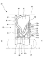
- FIG. 1 is a cross-sectional view of a main part of a sealing device 10 according to an embodiment of the present invention
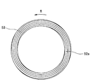
- FIG. 2 is an explanatory view of a thread groove 53 provided in the sealing device 10 according to an embodiment of the present invention.
- the sealing device 10 includes a sealing fluid (oil) on the machine inner side (oil side) A between a housing (seal housing) 20 and a rotary shaft 30 inserted through a shaft hole 21 provided in the housing 20.
- a sealing device (engine oil seal) 10 for sealing so as not to leak to the outside (atmosphere side) B, and a slinger 50 mounted on the outer periphery of the rotary shaft 30 and the inner periphery of the shaft hole 21 of the housing 20 It is comprised by the combination with the lip seal member 40 with which it is mounted
- the slinger 50 is made of a rigid material such as metal and has a sleeve 51 fixed (fitted) to the outer peripheral surface of the rotary shaft 30 and a radial direction provided at one end of the sleeve 51 (the inner side A end).
- a sleeve 51 fixed (fitted) to the outer peripheral surface of the rotary shaft 30 and a radial direction provided at one end of the sleeve 51 (the inner side A end).
- a helical thread groove 53 is formed that exerts an action of pushing the sealing fluid back toward the outer peripheral side (machine inner side A).
- the seal flange 52 is provided with an annular step portion 52b located in the middle in the radial direction.
- An annular thread groove forming region 53a in which a thread groove 53 is formed is provided on the machine end face 52a of the seal flange 52, and an annular thread groove in which the thread groove 53 is not formed on the inner peripheral side thereof.
- a non-formation region 53b is provided. Since the screw groove non-forming region 53b does not form the screw groove 53, it is provided as a flat surface perpendicular to the axial direction.
- the lip seal member 40 is attached (vulcanized and bonded) to the mounting ring 41 made of a rigid material such as metal that is fixed (fitted) to the inner peripheral surface of the shaft hole 21 of the housing 20.
- An outer peripheral seal portion 43 that seals between the housing 20 and the mounting ring 41 by contacting the inner peripheral surface of the shaft hole 21 of the housing 20 by the rubber-like elastic body 42.
- An end face attaching portion 44 attached to the end face portion of the mounting ring 41 and an outer peripheral side seal lip 46 slidably contacting the machine outer end face 52a of the seal flange 52 of the slinger 50 are provided integrally.
- a dust lip 45 is attached on the inner peripheral side of the end face adherent portion 44, and this dust lip 45 is made of fabric, but is integrally provided by the rubber-like elastic body 42. It may be.
- an inner peripheral side seal lip 47 that is located on the inner peripheral side of the outer peripheral side seal lip 46 and that slidably contacts the machine outer end surface 52a of the seal flange 52 in the slinger 50 is provided. .
- the inner peripheral side seal lip 47 protrudes from the end in the inner diameter direction of the rubber-like elastic body 42 toward the machine inner side A, and a cylindrical part 47a that is substantially concentric with the sleeve 51, and an inner side A of the cylindrical part 47a.
- a check lip 47b extending obliquely outward from the end (in the outer diameter direction and toward the machine inner side A) and slidably contacting the machine outer end surface 52a of the seal flange 52; Is provided.
- the radial thickness of the check lip 47b is set to be thinner than the radial thickness of the cylindrical portion 47a.
- a labyrinth seal 60 that is a minute gap is formed between the inner peripheral surface of the cylindrical portion 47 a and the outer peripheral surface of the sleeve 51.
- the outer peripheral side seal lip 46 is slidably in contact with the thread groove forming region 53a on the machine outer end surface 52a of the seal flange 52 with the outer peripheral side lip end 46a.
- the inner peripheral side seal lip 47 has an inner peripheral side lip end 47c and is slidably in contact with a non-thread groove forming region 53b on the machine end surface 52a of the seal flange 52.
- the sealing device 10 configured as described above slidably contacts the outer end surface 52a of the seal flange 52 of the slinger 50 with the outer peripheral lip end 46a of the outer peripheral seal lip 46 when the rotary shaft 30 rotates.
- the slinger 50 that rotates together with the rotating shaft 30 exhibits a fluid swinging action by the seal flange 52 and a fluid pumping action by the thread groove 53. Accordingly, even if there is a sealing fluid passing between the outer peripheral side seal lip 46 and the seal flange 52, it can be pushed back to the outer peripheral side (machine inner side A), and an excellent sealing function is exhibited.
- the space between the inner peripheral surface of the outer peripheral side seal lip 46 and the outer peripheral surface of the inner peripheral side seal lip 47 becomes negative pressure.
- the radial thickness of the cylindrical portion 47a is set to be thicker than the radial thickness of the check lip 47b, the cylindrical portion 47a is difficult to deform.
- the check lip 47b is easily deformed. Therefore, at the time of the negative pressure, the cylindrical portion 47a is not deformed, and only the check lip 47b opens in the outer diameter direction. Therefore, the pressure between the inner peripheral surface of the outer peripheral side seal lip 46 and the outer peripheral surface of the inner peripheral side seal lip 47 can be adjusted.
- the inner peripheral seal lip 47 adopts the above configuration, even if the sealing fluid is accumulated in the space between the inner peripheral surface of the outer peripheral seal lip 46 and the outer peripheral surface of the inner peripheral seal lip 47.
- the cylindrical portion 47a is deformed by the weight of the sealing fluid and does not come into contact with the sleeve 51 in the slinger 50.
- the contact state between the check lip 47b and the outer end surface 52a of the seal flange 52 can be stabilized.
- the sealing function by the inner peripheral lip end 47c is exhibited, and this prevents the sealing fluid from flowing out from the outer peripheral sealing lip 46 toward the dust lip 45, so that the sealing fluid passes through the dust lip 45. Leakage to the outside B can be suppressed.
- outer peripheral side seal lip 46 and the inner peripheral side seal lip 47 of the present invention are in contact with the seal flange 52 of the slinger 50, lower torque can be realized as compared with a sealing device having a general radial lip structure. Can do.
- the check lip 47b in the inner peripheral side seal lip 47 according to the present embodiment is thin, the sliding torque hardly increases, and the occurrence of energy loss due to the increase of the sliding torque is suppressed. be able to.
- a labyrinth seal 60 is formed by providing a minute gap between the inner circumferential surface of the cylindrical portion 47a and the outer circumferential surface of the sleeve 51, leakage of the sealing fluid to the outside B of the machine through this gap. Intrusion of dust from the outside B can be prevented.
- a thread groove forming region 53a is provided on the outer peripheral side of the stepped part 52b provided on the seal flange 52, and no thread groove is formed on the inner peripheral side of the stepped part 52b.
- the region 53b is provided, the arrangement of these regions may be such that both the screw groove forming region 53a and the screw groove non-forming region 53b are provided on the outer peripheral side of the stepped portion 52b as shown in FIG. Good.
- the check lip 47b comes into slidable contact with the non-thread groove forming region 53b provided on the outer peripheral side of the stepped portion 52b.
Landscapes
- Engineering & Computer Science (AREA)
- General Engineering & Computer Science (AREA)
- Mechanical Engineering (AREA)
- Physics & Mathematics (AREA)
- Fluid Mechanics (AREA)
- Sealing With Elastic Sealing Lips (AREA)
- Sealing Devices (AREA)
Abstract
静止漏れが発生するのを抑制することができる密封装置を提供する。この目的達成のため、密封装置は、ハウジングとハウジングの軸孔に挿通する回転軸との間で密封流体をシールするものであって、回転軸の外周に装着されるシールフランジに対し、軸孔内周に装着される外周側シールリップが摺動可能に接触し、回転軸の回転時に流体ポンピング作用を発揮するネジ溝がシールフランジに設けられ、シールフランジにおけるネジ溝の内周側には、ネジ溝が設けられていない領域が設定され、外周側シールリップの内周側には、軸方向の機内側に向けて突出する円筒部と、円筒部に対して薄肉であり、円筒部の長さ方向の端部から斜め外方へ向けて延在し、前記領域と摺動可能に接触するチェックリップと、を有する内周側シールリップを備える。
Description
本発明は、自動車や一般機械、産業機械等において機内の密封流体が機外へ漏洩するのを抑制する密封装置に関する。本発明の密封装置は例えば、自動車関連分野において機内油をシールする回転用オイルシールとして用いられる。
従来から図4(A)に示すように、ハウジング520とこのハウジング520に設けた軸孔521に挿通する回転軸530との間で機内側Aの密封流体が機外側Bへ漏洩しないようシールする密封装置510であって、回転軸530の外周に装着されるスリンガー550と、このスリンガー550の機外側Bに位置してハウジング520の軸孔521内周に装着されるリップシール部材540との組み合わせよりなる密封装置510が知られている。
スリンガー550は、金属等の剛材製であって、回転軸530の外周面に嵌合されるスリーブ551と、このスリーブ551の一端に設けられたシールフランジ552とを一体に有し、シールフランジ552の機外側端面552aには、回転軸530の回転時に遠心力による流体ポンピング作用を発揮するネジ溝553が設けられている。
一方、リップシール部材540は、ハウジング520の軸孔521内周面に嵌合される取付環541と、この取付環541に被着されたゴム状弾性体542とを有し、このゴム状弾性体542によって、スリンガー550におけるシールフランジ552の機外側端面552aに摺動可能に接触するシールリップ546が設けられている。
上記構成の密封装置510は、シールリップ546がシールフランジ552の機外側端面552aに摺動可能に接触することにより密封流体をシールし、またシールフランジ552の機外側端面552aに設けたネジ溝553が回転軸530の回転時に遠心力による流体ポンピング作用を発揮して密封流体を機内側Aへ押し戻すことから、優れたシール効果を発揮することができる。
しかしながら上記密封装置510に対しては、以下の点で更なる機能の向上が求められる。
すなわち上記密封装置510においては、シールリップ546がシールフランジ552の機外側端面552aと摺動可能に接触することにより密封流体をシールするとともにシールフランジ552の機外側端面552aに設けたネジ溝553が回転時に遠心力による流体ポンピング作用を発揮して密封流体を機内側Aへ押し戻すことから優れたシール効果を発揮することができる。しかし、密封装置510は、その構成としてネジ溝553がシールリップ546のリップ端と交差するように配置されている。したがって、回転軸530の回転が停止することにより遠心力が消失すると、これに伴ってネジ溝553による流体ポンピング作用が発揮されず、密封流体がネジ溝553を伝ってシールリップ546の内周側へ通過し、機外側Bへ漏洩すること(いわゆる静止漏れが発生すること)が懸念される。
本発明は以上の点に鑑みて、シールフランジに対しシールリップが摺動可能に接触し、回転時に流体ポンピング作用を発揮するネジ溝がシールフランジに設けられている密封装置において、静止漏れが発生するのを抑制することができる密封装置を提供することを目的とする。
上述した技術的課題を有効に解決するための手段として、本発明の密封装置は、ハウジングと前記ハウジングに設けた軸孔に挿通する回転軸との間で機内側の密封流体が機外側へ漏洩しないようシールする密封装置であって、前記回転軸の外周に装着されるシールフランジに対し、前記ハウジングの軸孔内周に装着される外周側シールリップが摺動可能に接触し、前記回転軸の回転時に流体ポンピング作用を発揮するネジ溝が前記外周側シールリップのリップ端と交差するように前記シールフランジに設けられている密封装置において、前記シールフランジにおける前記ネジ溝の内周側には、前記ネジ溝が設けられていない領域が設定され、前記外周側シールリップの内周側には、軸方向の機内側に向けて突出する円筒部と、この円筒部に対して薄肉であり、前記円筒部の長さ方向の端部から斜め外方へ向けて延在し、前記領域と摺動可能に接触するチェックリップと、を有する内周側シールリップを備えたことを特徴とする。
また、前記外周側シールリップの内周面と前記内周側シールリップの外周面との間の空間が負圧となったときに、前記チェックリップは、外径方向に開弁してもよい。
また、前記シールフランジの内周側には、回転軸に固定されるスリーブが形成され、このスリーブの外周面と前記円筒部の内周面との間には、微小の隙間を設定することでラビリンスシールが形成されていてもよい。
本発明によれば、シールフランジに対し外周側シールリップ及び内周側シールリップが摺動可能に接触し、回転時に流体ポンピング作用を発揮するネジ溝がシールフランジに設けられている密封装置において、静止漏れが発生するのを抑制することができる。
以下において、本発明の実施形態に係る密封装置10について図面に基づき詳細に説明する。図1は、本発明の実施形態に係る密封装置10の要部断面図であり、図2は、本発明の実施形態に係る密封装置10に備えられるネジ溝53の説明図である。
本実施形態に係る密封装置10は、ハウジング(シールハウジング)20と、このハウジング20に設けた軸孔21に挿通される回転軸30との間で機内側(油側)Aの密封流体(油)が機外側(大気側)Bへ漏洩しないように密封する密封装置(エンジン用オイルシール)10であって、回転軸30の外周に装着されるスリンガー50と、ハウジング20の軸孔21内周に装着されるリップシール部材40との組み合わせにより構成されている。
スリンガー50は、金属等の剛材製であって、回転軸30の外周面に固定(嵌合)されるスリーブ51と、このスリーブ51の一端(機内側A端部)に設けられた径方向外向きのシールフランジ(フランジ部)52とを一体に有し、シールフランジ52の機外側端面52aに図2に示すような、回転軸30の回転時に遠心力による流体ポンピング作用を発揮することにより密封流体を外周側(機内側A)へ向けて押し戻す作用を発揮する螺旋状のネジ溝53が形成されている。また、このシールフランジ52には、その径方向の中ほどに位置する環状の段差部52bが設けられている。なお、図2における矢印eは、回転軸30の回転方向を示す。
また、シールフランジ52の機外側端面52aには、ネジ溝53が形成された環状のネジ溝形成領域53aが設けられ、その内周側には、ネジ溝53が形成されていない環状のネジ溝非形成領域53bが設けられている。このネジ溝非形成領域53bはネジ溝53を形成していないため、軸方向直角の平坦面として設けられている。
一方、リップシール部材40は、ハウジング20の軸孔21内周面に固定(嵌合)される金属等の剛材よりなる取付環41と、この取付環41に被着(加硫接着)されたゴム状弾性体42とを有し、このゴム状弾性体42によって、ハウジング20の軸孔21内周面に接触することによりハウジング20及び取付環41の間をシールする外周シール部43と、取付環41の端面部に被着された端面被着部44と、スリンガー50におけるシールフランジ52の機外側端面52aに摺動可能に接触する外周側シールリップ46と、が一体に設けられている。また、端面被着部44の内周側に位置してダストリップ45が取り付けられ、このダストリップ45はファブリックよりなるものとされているが、上記ゴム状弾性体42によって一体に設けられたものであっても良い。
特に、本実施形態においては、外周側シールリップ46の内周側に位置し、スリンガー50におけるシールフランジ52の機外側端面52aに摺動可能に接触する内周側シールリップ47が設けられている。
内周側シールリップ47は、ゴム状弾性体42の内径方向の端部から機内側Aに向けて突出し、スリーブ51とほぼ同心状にある円筒部47aと、この円筒部47aの機内側Aの端部から斜め外方(外径方向であってかつ機内側Aに向けての方向)へ向けて延在し、シールフランジ52の機外側端面52aに摺動可能に接触するチェックリップ47bと、を備える。また、チェックリップ47bの径方向の厚みは、円筒部47aの径方向の厚みよりも薄肉に設定されている。さらに、円筒部47aの内周面とスリーブ51の外周面との間には、微小の隙間であるラビリンスシール60が形成されている。
外周側シールリップ46は外周側リップ端46aをもってシールフランジ52の機外側端面52aにおけるネジ溝形成領域53aと摺動可能に接触する。一方で、内周側シールリップ47は内周側リップ端47cをもってシールフランジ52の機外側端面52aにおけるネジ溝非形成領域53bと摺動可能に接触する。
以上のように構成された密封装置10は、回転軸30の回転時に外周側シールリップ46の外周側リップ端46aをもってスリンガー50のシールフランジ52の機外側端面52aに摺動可能に接触することによりシール機能を発揮するほか、回転軸30とともに回転するスリンガー50がシールフランジ52による流体振り切り作用およびネジ溝53による流体ポンピング作用を発揮する。これにより、外周側シールリップ46およびシールフランジ52の間を通過する密封流体があってもこれを外周側(機内側A)へ押し戻すことが可能とされ、優れたシール機能が発揮される。
また、シールフランジ52による流体振り切り作用及び流体ポンピング作用によって、外周側シールリップ46の内周面と内周側シールリップ47の外周面との間の空間が負圧になる。しかし、本実施形態に係る密封装置10は、円筒部47aの径方向の厚みがチェックリップ47bの径方向の厚みに対して厚肉に設定されているため、円筒部47aは、変形しづらい一方で、チェックリップ47bは、変形しやすい。したがって、前記負圧時には、円筒部47aは変形せず、チェックリップ47bのみが外径方向に開弁する。よって、外周側シールリップ46の内周面と内周側シールリップ47の外周面との間の圧力を調整することができる。
また、内周側シールリップ47が上記構成を採用することに伴い、外周側シールリップ46の内周面と内周側シールリップ47の外周面との間の空間に密封流体が溜まったとしても、円筒部47aが密封流体の重量で変形し、スリンガー50におけるスリーブ51と接触することがなくなる。加えて、チェックリップ47bとシールフランジ52の機外側端面52aとの接触状態を安定させることができる。
また、回転軸30の回転が停止すると遠心力が消失し、これに伴って上記流体振り切り作用および流体ポンピング作用が一時停止するため、一部の密封流体がネジ溝53を伝って機内側Aから外周側シールリップ46の内周側へ流出することが懸念される。しかし、この外周側シールリップ46の内周側では、チェックリップ47bにおける内周側リップ端47cがネジ溝非形成領域53bと接触することにより機外側Bへの漏れ路を閉塞している。したがって内周側リップ端47cによるシール機能が発揮され、これにより密封流体が外周側シールリップ46からダストリップ45のほうへ流出するのが抑制されるため、密封流体がダストリップ45を通過して機外側Bへ漏洩するのを抑制することができる。
また、本発明の外周側シールリップ46及び内周側シールリップ47は、スリンガー50におけるシールフランジ52と接触するため、一般的なラジアルリップ構造の密封装置と比較して低トルク化を実現することができる。特に、本実施形態に係る内周側シールリップ47におけるチェックリップ47bは、薄肉であるため、摺動トルクがほとんど増大せず、摺動トルクが増大してエネルギーロス等が発生するのを抑制することができる。
また、円筒部47aの内周面とスリーブ51の外周面との間には、微小の隙間を設けることでラビリンスシール60が形成されるため、この隙間を通じて機外側Bへの密封流体の漏れや、機外側Bからのダストの侵入を防止することができる。
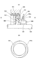
なお、上記実施形態では、図1に示したように、シールフランジ52に設けられた段差部52bの外周側にネジ溝形成領域53aが設けられるとともに段差部52bの内周側にネジ溝非形成領域53bが設けられているが、これらの領域の配置については、図3に示すように段差部52bの外周側にネジ溝形成領域53a及びネジ溝非形成領域53bを双方ともに設けるようにしてもよい。そして、この例では、段差部52bの外周側に設けられたネジ溝非形成領域53bに対してチェックリップ47bが摺動可能に接触することとなる。
10 密封装置
20 ハウジング
21 軸孔
30 回転軸
40 リップシール部材
41 取付環
42 ゴム状弾性体
43 外周シール部
44 端面被着部
45 ダストリップ
46 外周側シールリップ
46a 外周側リップ端
47 内周側シールリップ
47a 円筒部
47b チェックリップ
47c 内周側リップ端
50 スリンガー
51 スリーブ
52 シールフランジ
52a 機外側端面
52b 段差部
53 ネジ溝
53a ネジ溝形成領域
53b ネジ溝非形成領域
60 ラビリンスシール
A 機内側
B 機外側
20 ハウジング
21 軸孔
30 回転軸
40 リップシール部材
41 取付環
42 ゴム状弾性体
43 外周シール部
44 端面被着部
45 ダストリップ
46 外周側シールリップ
46a 外周側リップ端
47 内周側シールリップ
47a 円筒部
47b チェックリップ
47c 内周側リップ端
50 スリンガー
51 スリーブ
52 シールフランジ
52a 機外側端面
52b 段差部
53 ネジ溝
53a ネジ溝形成領域
53b ネジ溝非形成領域
60 ラビリンスシール
A 機内側
B 機外側
Claims (3)
- ハウジングと前記ハウジングに設けた軸孔に挿通する回転軸との間で機内側の密封流体が機外側へ漏洩しないようシールする密封装置であって、
前記回転軸の外周に装着されるシールフランジに対し、前記ハウジングの軸孔内周に装着される外周側シールリップが摺動可能に接触し、
前記回転軸の回転時に流体ポンピング作用を発揮するネジ溝が前記外周側シールリップのリップ端と交差するように前記シールフランジに設けられている密封装置において、
前記シールフランジにおける前記ネジ溝の内周側には、前記ネジ溝が設けられていない領域が設定され、
前記外周側シールリップの内周側には、軸方向の機内側に向けて突出する円筒部と、この円筒部に対して薄肉であり、前記円筒部の長さ方向の端部から斜め外方へ向けて延在し、前記領域と摺動可能に接触するチェックリップと、を有する内周側シールリップを備えたことを特徴とする密封装置。 - 請求項1に記載の密封装置であって、
前記外周側シールリップの内周面と前記内周側シールリップの外周面との間の空間が負圧となったときに、前記チェックリップは、外径方向に開弁することを特徴とする密封装置。 - 請求項1又は2に記載の密封装置であって、
前記シールフランジの内周側には、回転軸に固定されるスリーブが形成され、
このスリーブの外周面と前記円筒部の内周面との間には、微小の隙間を設定することでラビリンスシールが形成されていることを特徴とする密封装置。
Priority Applications (1)
| Application Number | Priority Date | Filing Date | Title |
|---|---|---|---|
| JP2017536593A JPWO2017098985A1 (ja) | 2015-12-08 | 2016-12-01 | 密封装置 |
Applications Claiming Priority (2)
| Application Number | Priority Date | Filing Date | Title |
|---|---|---|---|
| JP2015-239574 | 2015-12-08 | ||
| JP2015239574 | 2015-12-08 |
Publications (1)
| Publication Number | Publication Date |
|---|---|
| WO2017098985A1 true WO2017098985A1 (ja) | 2017-06-15 |
Family
ID=59014108
Family Applications (1)
| Application Number | Title | Priority Date | Filing Date |
|---|---|---|---|
| PCT/JP2016/085676 Ceased WO2017098985A1 (ja) | 2015-12-08 | 2016-12-01 | 密封装置 |
Country Status (2)
| Country | Link |
|---|---|
| JP (1) | JPWO2017098985A1 (ja) |
| WO (1) | WO2017098985A1 (ja) |
Citations (6)
| Publication number | Priority date | Publication date | Assignee | Title |
|---|---|---|---|---|
| JPS49105739U (ja) * | 1973-01-08 | 1974-09-10 | ||
| US4844480A (en) * | 1987-12-04 | 1989-07-04 | Ford Motor Company | Pressure sensitive shaft sealing ring |
| JPH0378169U (ja) * | 1989-11-30 | 1991-08-07 | ||
| JP2009150417A (ja) * | 2007-12-18 | 2009-07-09 | Ntn Corp | 車輪用軸受装置 |
| JP2009197883A (ja) * | 2008-02-21 | 2009-09-03 | Ntn Corp | 車輪用軸受装置 |
| JP2014070728A (ja) * | 2012-10-02 | 2014-04-21 | Nok Corp | オイルシール |
-
2016
- 2016-12-01 WO PCT/JP2016/085676 patent/WO2017098985A1/ja not_active Ceased
- 2016-12-01 JP JP2017536593A patent/JPWO2017098985A1/ja active Pending
Patent Citations (6)
| Publication number | Priority date | Publication date | Assignee | Title |
|---|---|---|---|---|
| JPS49105739U (ja) * | 1973-01-08 | 1974-09-10 | ||
| US4844480A (en) * | 1987-12-04 | 1989-07-04 | Ford Motor Company | Pressure sensitive shaft sealing ring |
| JPH0378169U (ja) * | 1989-11-30 | 1991-08-07 | ||
| JP2009150417A (ja) * | 2007-12-18 | 2009-07-09 | Ntn Corp | 車輪用軸受装置 |
| JP2009197883A (ja) * | 2008-02-21 | 2009-09-03 | Ntn Corp | 車輪用軸受装置 |
| JP2014070728A (ja) * | 2012-10-02 | 2014-04-21 | Nok Corp | オイルシール |
Also Published As
| Publication number | Publication date |
|---|---|
| JPWO2017098985A1 (ja) | 2018-09-27 |
Similar Documents
| Publication | Publication Date | Title |
|---|---|---|
| JP6445085B2 (ja) | 密封装置 | |
| JP6054135B2 (ja) | オイルシール | |
| JP6000845B2 (ja) | 密封装置 | |
| JP5964201B2 (ja) | オイルシール | |
| JP6033996B1 (ja) | 密封装置 | |
| WO2014021179A1 (ja) | 密封装置 | |
| EP2749796B1 (en) | Sealing device | |
| JPWO2016111303A1 (ja) | 密封装置 | |
| JP6479831B2 (ja) | メカニカルシール | |
| JP6444756B2 (ja) | 密封装置 | |
| WO2017090583A1 (ja) | 密封装置 | |
| JP2014070728A (ja) | オイルシール | |
| JP6650742B2 (ja) | 密封装置 | |
| JP6378548B2 (ja) | 密封装置 | |
| WO2017094599A1 (ja) | 密封装置 | |
| JP6625340B2 (ja) | 密封装置 | |
| WO2017098985A1 (ja) | 密封装置 | |
| JP2018063050A (ja) | シール部材 | |
| JP6545486B2 (ja) | 密封装置 | |
| JP2010025137A (ja) | 回転用オイルシール | |
| JP6628207B2 (ja) | 密封装置 | |
| JP6368152B2 (ja) | 密封装置 | |
| JP2014109354A (ja) | 密封装置 | |
| JP2024056552A (ja) | 密封構造 | |
| JP2008025628A (ja) | 密封装置 |
Legal Events
| Date | Code | Title | Description |
|---|---|---|---|
| ENP | Entry into the national phase |
Ref document number: 2017536593 Country of ref document: JP Kind code of ref document: A |
|
| 121 | Ep: the epo has been informed by wipo that ep was designated in this application |
Ref document number: 16872883 Country of ref document: EP Kind code of ref document: A1 |
|
| NENP | Non-entry into the national phase |
Ref country code: DE |
|
| 122 | Ep: pct application non-entry in european phase |
Ref document number: 16872883 Country of ref document: EP Kind code of ref document: A1 |