WO2017086051A1 - Imaging lens - Google Patents
Imaging lens Download PDFInfo
- Publication number
- WO2017086051A1 WO2017086051A1 PCT/JP2016/079993 JP2016079993W WO2017086051A1 WO 2017086051 A1 WO2017086051 A1 WO 2017086051A1 JP 2016079993 W JP2016079993 W JP 2016079993W WO 2017086051 A1 WO2017086051 A1 WO 2017086051A1
- Authority
- WO
- WIPO (PCT)
- Prior art keywords
- lens
- refractive power
- object side
- conditional expression
- optical axis
- Prior art date
Links
Images


Classifications
-
- G—PHYSICS
- G02—OPTICS
- G02B—OPTICAL ELEMENTS, SYSTEMS OR APPARATUS
- G02B13/00—Optical objectives specially designed for the purposes specified below
- G02B13/04—Reversed telephoto objectives
-
- G—PHYSICS
- G02—OPTICS
- G02B—OPTICAL ELEMENTS, SYSTEMS OR APPARATUS
- G02B13/00—Optical objectives specially designed for the purposes specified below
- G02B13/001—Miniaturised objectives for electronic devices, e.g. portable telephones, webcams, PDAs, small digital cameras
- G02B13/0015—Miniaturised objectives for electronic devices, e.g. portable telephones, webcams, PDAs, small digital cameras characterised by the lens design
- G02B13/002—Miniaturised objectives for electronic devices, e.g. portable telephones, webcams, PDAs, small digital cameras characterised by the lens design having at least one aspherical surface
- G02B13/0045—Miniaturised objectives for electronic devices, e.g. portable telephones, webcams, PDAs, small digital cameras characterised by the lens design having at least one aspherical surface having five or more lenses
-
- G—PHYSICS
- G02—OPTICS
- G02B—OPTICAL ELEMENTS, SYSTEMS OR APPARATUS
- G02B9/00—Optical objectives characterised both by the number of the components and their arrangements according to their sign, i.e. + or -
- G02B9/62—Optical objectives characterised both by the number of the components and their arrangements according to their sign, i.e. + or - having six components only
-
- G—PHYSICS
- G02—OPTICS
- G02B—OPTICAL ELEMENTS, SYSTEMS OR APPARATUS
- G02B13/00—Optical objectives specially designed for the purposes specified below
- G02B13/18—Optical objectives specially designed for the purposes specified below with lenses having one or more non-spherical faces, e.g. for reducing geometrical aberration
Definitions
- This technology relates to a technical field of an imaging lens suitable for, for example, an in-vehicle camera, a surveillance camera, a mobile device camera, and the like.
- imaging apparatuses such as in-vehicle cameras, surveillance cameras, and mobile device cameras have been widely used.
- image pickup devices a wide angle of view is secured with respect to the image pickup lens as the image pickup element represented by a CCD or CMOS that captures an image formed by the image pickup lens is downsized and the number of pixels is increased.
- the image pickup element represented by a CCD or CMOS that captures an image formed by the image pickup lens is downsized and the number of pixels is increased.
- As an imaging lens satisfying such a requirement for example, there are lenses described in Patent Documents 1 to 3 below.
- Patent Document 1 proposes an imaging lens that includes five lenses in four groups and has a total angle of view exceeding 180 degrees with chromatic aberration suppressed by joining a fourth lens made of plastic and a fifth lens made of plastic. Yes.
- a bonding agent or process for bonding by bonding plastic lenses it is necessary to use a bonding agent or process for bonding by bonding plastic lenses, and furthermore, the shape of the bonding surface changes with temperature change, and the bonded lenses easily peel off. There is a risk said.
- Patent Document 2 proposes an imaging lens having a total angle of view exceeding 180 degrees composed of five lenses in five groups. However, since the rear group has two separated positive and negative elements, it is difficult to correct chromatic aberration and it is difficult to obtain good resolution performance up to the periphery.
- Patent Document 3 proposes an imaging lens having six lenses in six groups and a power arrangement of lenses from the object side, with all angles of view exceeding 180 degrees, which is negative, positive, positive and negative.
- the material of the first lens, the fourth lens, and the fifth lens is formed of glass, and among the constituent lenses, d of the glass of the first lens having the largest volume and effective lens surface.
- the imaging lens having an F value of around 2 is a high-cost imaging lens.
- the ratio of the distance from the object side surface of the first lens to the image plane to the focal length of the entire imaging lens system, the radius of curvature on the optical axis of the object side surface of the first lens and the focal point of the entire imaging lens system From the ratio with the distance, it is designed to be further miniaturized.
- an imaging lens having a wide angle of 150 degrees or more, high image quality, small size, low cost, and maintaining stable quality even in harsh environments such as on-vehicle cameras.
- this technology imaging lens provides an imaging lens with a wide angle of over 150 degrees, high image quality, small size, low cost, and stable quality even in harsh environments such as in-vehicle cameras.
- the purpose is to do.
- the first imaging lens includes a meniscus first lens having negative refractive power and a convex surface facing the object side, which is arranged in order from the object side to the image plane side, and negative refraction
- a second meniscus lens having a convex surface facing the object side, a third meniscus lens having a positive refractive power and a concave surface facing the object side, an aperture stop, and a positive refractive power
- a biconvex fourth lens having negative refractive power
- a biconcave fifth lens having negative refractive power and a biconvex sixth lens having positive refractive power.
- the second imaging lens includes a first meniscus lens having negative refractive power and a convex surface facing the object side, which is arranged in order from the object side to the image plane side, and negative refraction
- a biconvex fourth lens having negative refractive power, a biconcave fifth lens having negative refractive power, and a biconvex sixth lens having positive refractive power.
- Consists of 6 elements in 6 groups with independent lenses the total angle of view is 150 degrees or more, and the following conditional expression (1), conditional expression (2) and conditional expression (8) are satisfied.
- ⁇ d1 Abbe number Nd1 at the d-line of the first lens
- Nd1 Refractive index R1 at the d-line of the first lens
- R1 Radius of curvature on the optical axis of the object side surface of the first lens f: Focal length of the entire system.
- the third imaging lens includes a first meniscus lens having negative refractive power and a convex surface facing the object side, which is arranged in order from the object side to the image plane side, and negative refraction
- a second meniscus lens having a convex surface facing the object side, a third meniscus lens having a positive refractive power and a concave surface facing the object side, an aperture stop, and a positive refractive power
- a biconvex fourth lens having negative refractive power, a biconcave fifth lens having negative refractive power, and a biconvex sixth lens having positive refractive power.
- a fourth imaging lens includes a first meniscus lens having negative refractive power and a convex surface facing the object side, which is arranged in order from the object side to the image plane side, and negative refraction
- a fifth imaging lens includes a first meniscus lens having negative refractive power and a convex surface facing the object side, which is arranged in order from the object side to the image plane side, and negative refraction
- the first imaging lens to the fifth imaging lens according to the present technology have a wide angle of 150 degrees or more, a high image quality, a small size, a low cost, and a harsh vehicle camera or the like. It is possible to provide an imaging lens that maintains stable quality even in an environment.
- the wide angle of all angles is 150 degrees or more, high image quality, small size, and low cost.
- FIG. 3 is an aberration diagram showing various aberrations in Numerical Example 1 in which specific numerical values are applied to the imaging lens illustrated in FIG. 1. It is sectional drawing which shows the 2nd structural example of an imaging lens.
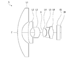
- FIG. 4 is an aberration diagram showing various aberrations in Numerical Example 2 in which specific numerical values are applied to the imaging lens illustrated in FIG. 3. It is sectional drawing which shows the 3rd structural example of an imaging lens.
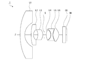
- FIG. 6 is an aberration diagram showing various aberrations in Numerical Example 3 in which specific numerical values are applied to the imaging lens illustrated in FIG. 5. It is sectional drawing which shows the 4th structural example of an imaging lens.
- FIG. 10 is an aberration diagram illustrating various aberrations in Numerical Example 4 in which specific numerical values are applied to the imaging lens illustrated in FIG. 7. It is sectional drawing which shows the 5th structural example of an imaging lens.
- FIG. 10 is an aberration diagram illustrating various aberrations in Numerical Example 5 in which specific numerical values are applied to the imaging lens illustrated in FIG. 9. It is sectional drawing which shows the 6th structural example of an imaging lens.
- FIG. 12 is an aberration diagram illustrating various aberrations in Numerical Example 6 in which specific numerical values are applied to the imaging lens illustrated in FIG. 11. It is sectional drawing which shows the 7th structural example of an imaging lens.
- FIG. 14 is an aberration diagram illustrating various aberrations in Numerical Example 7 in which specific numerical values are applied to the imaging lens illustrated in FIG.
- FIG. 16 is an aberration diagram illustrating various aberrations in Numerical Example 8 in which specific numerical values are applied to the imaging lens illustrated in FIG. 15. It is sectional drawing which shows the 9th structural example of an imaging lens.
- FIG. 18 is an aberration diagram illustrating various aberrations in Numerical Example 9 in which specific numerical values are applied to the imaging lens illustrated in FIG. 17. It is sectional drawing which shows the 10th structural example of an imaging lens.
- FIG. 20 is an aberration diagram illustrating various aberrations in Numerical Example 10 in which specific numerical values are applied to the imaging lens illustrated in FIG. 19. It is sectional drawing which shows the 11th structural example of an imaging lens.
- FIG. 16 is an aberration diagram illustrating various aberrations in Numerical Example 8 in which specific numerical values are applied to the imaging lens illustrated in FIG. 15. It is sectional drawing which shows the 9th structural example of an imaging lens.
- FIG. 18 is an aberration diagram illustrating various aberrations in Numerical Example 9 in which specific numerical values are applied to the imaging lens illustrated in FIG
- FIG. 22 is an aberration diagram illustrating various aberrations in Numerical Example 11 in which specific numerical values are applied to the imaging lens illustrated in FIG. 21. It is sectional drawing which shows the 12th structural example of an imaging lens.
- FIG. 24 is an aberration diagram illustrating various aberrations in Numerical Example 12 in which specific numerical values are applied to the imaging lens illustrated in FIG. 23. It is explanatory drawing which shows the example 1 of installation as a vehicle-mounted use. It is explanatory drawing which shows the example 2 of installation as a vehicle-mounted use.
- the sign of the lens shape such as convex surface and concave surface
- the refractive power of the lens such as positive refractive power and negative refractive power
- the radius of curvature is also defined in the paraxial region
- the polarity is positive for the convex surface on the object side and negative for the convex surface on the image side.
- the focal length of each lens, the synthesis, and the entire system is defined as a value at 587.56 nm of the d-line as a wavelength.
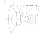
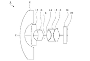
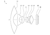
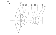
- FIG. 1 is a cross-sectional view illustrating Numerical Example 1 of the imaging lens according to the embodiment of the present technology.
- the imaging lenses of Examples 2 to 12 to be described later have the same basic configuration as that of Example 1 shown in FIG. 1 and the method shown in FIG. An imaging lens according to an embodiment of the technology will be described.
- the left side is the object side
- the right side is the image side
- the optical axis is represented by Z.
- the imaging lenses (imaging lens 1 to imaging lens 12) according to the embodiments of the present technology are arranged in order from the object side to the image side along the optical axis Z from the first lens L1, the second lens L2, and the third lens.
- L3, the 4th lens L4, the 5th lens L5, and the 6th lens L6 are the lenses of 6 groups 6 pieces composition arranged by each independently.
- An aperture stop S is disposed between the third lens L3 and the fourth lens L4. By disposing the aperture stop S between the third lens L3 and the fourth lens L4, it is possible to reduce the size in the radial direction and to suppress lateral chromatic aberration.
- FIG. 1 also illustrates the image plane IM of the imaging lens in consideration of the case where the imaging lens is applied to the imaging apparatus. Also, a cover glass and a parallel plate CG that are assumed to be a low-pass filter required when the imaging lens is applied to the imaging device are disposed between the sixth lens L6 of the imaging lens and the image plane IM.
- the first lens L1 has a negative refractive power and is formed in a meniscus shape having a convex surface facing the object side. Such a configuration of the first lens L1 is advantageous for widening the angle and correcting distortion.
- the first lens L1 is formed of a glass lens. This is because the first lens L1 arranged closest to the object side is required to have weather resistance, impact resistance, wear resistance, and the like, particularly considering in-vehicle use. Further, both surfaces of the first lens L1 are formed on a spherical surface, but there is a concern that the cost may increase when the material is formed of glass and an aspheric surface. Absent.
- the second lens L2 has a negative refractive power and is formed in a meniscus shape having a convex surface facing the object side.
- the third lens L3 has a positive refractive power and is formed in a meniscus shape having a concave surface facing the object side.
- the biconvex sixth lens L6 is arranged, and by adopting such a triplet configuration, it becomes easy to correct various aberrations affecting the imaging performance.
- the sixth lens L6 having positive refractive power on the most image side in the imaging lens, correction of the distance from the image plane that is the imaging plane and the incident angle of off-axis rays on the image plane, That is, the back focus and shading can be easily corrected.
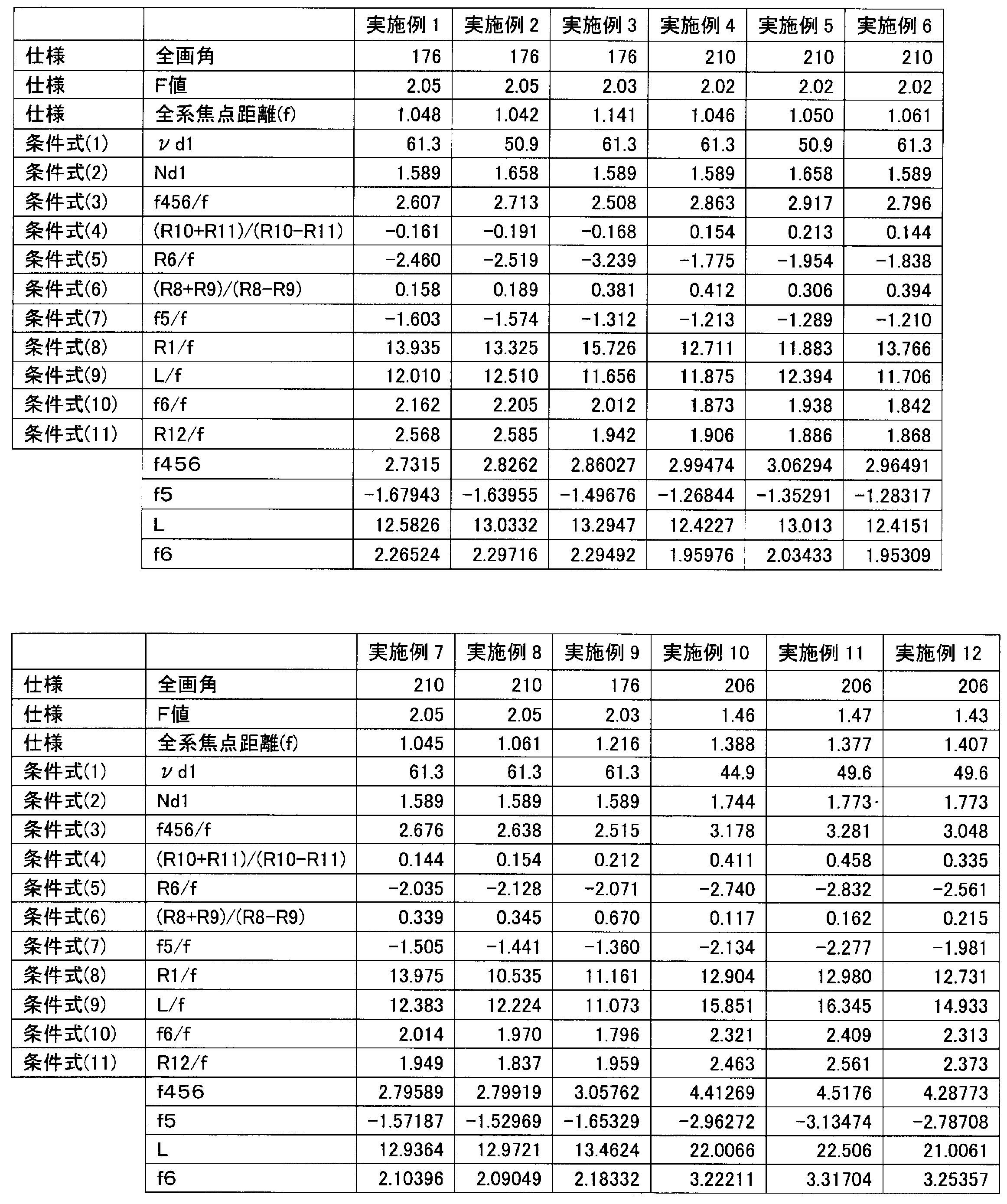
- the imaging lens of the present technology may include all of conditional expression (1), conditional expression (2), and conditional expression (3), or conditional expression (1), conditional expression (2), and conditional expression (8), or Conditional expression (1), conditional expression (2), and conditional expression (9) are all satisfied, or conditional expression (10) or conditional expression (11) is satisfied.
- Conditional expression (1) is an Abbe number at the d-line 587.56 nm of the material constituting the first lens L1
- conditional expression (2) is an expression defining the refractive index.
- the first lens L1 is a lens element having the maximum volume and the maximum optical effective area among the six lens elements constituting the imaging lens of the present technology. Another object of the present technology is to provide a low-cost imaging lens. Therefore, the material constituting the first lens L1 needs to be a low-cost material, and the conditional selection (1) and the conditional expression (2) define the selection range of the material in order to reduce the cost. .
- the material constituting the first lens L1 is assumed to be glass, but other materials than glass can also be used.
- Conditional expression (3) is an expression defining the ratio of the combined focal length of the fourth lens L4, fifth lens L5, and sixth lens L6 arranged on the image side of the aperture stop S to the focal length of the entire system. .
- the combined refractive power of the fourth lens L4, the fifth lens L5, and the sixth lens L6 becomes strong, and it becomes difficult to ensure the back focus as an imaging lens. It interferes with the focus adjustment of an image plane, that is, an image sensor represented by a CCD or a CMOS. It is also difficult to correct various aberrations including spherical aberration and field curvature.
- the combined refractive power of the fourth lens L4, the fifth lens L5, and the sixth lens L6 becomes weak, the back focus as the imaging lens becomes long, the overall length as the imaging lens also becomes long, and the large size There is a hindrance that causes
- Conditional expression (8) is an expression that defines the ratio between the radius of curvature on the optical axis of the object side surface of the first lens L1 and the focal length of the imaging lens.
- the expression means that the object side surface of the first lens L1 is convex toward the object side.
- Below the lower limit as a numerical value the radius of curvature on the optical axis of the object side surface of the first lens L1 becomes small, the refractive power of the first lens L1 becomes weak, and it becomes difficult to widen the angle.
- the numerical upper limit is exceeded, the radius of curvature on the optical axis of the object-side surface of the first lens L1 increases, and the cost increases due to the increase in the effective optical diameter of the object-side surface of the first lens L1. Becomes large as an imaging lens, and the commercial value is impaired. Further, it becomes difficult to correct distortion.
- Conditional expression (9) is an expression that prescribes the ratio between the total length of the imaging lens and the focal length defined as the distance from the vertex on the optical axis of the object-side surface of the first lens to the image plane. If the numerical value is below the lower limit, the entire length of the imaging lens is shortened and the size can be reduced. However, it is difficult to widen the angle or to correct various aberrations. If the upper limit as a numerical value is exceeded, the entire length of the imaging lens becomes long, and the value as a product is impaired.
- Conditional expression (10) is an expression that defines the ratio between the focal length of the sixth lens L6 and the focal length of the entire imaging lens system.
- the expression means that the sixth lens L6 has a positive refractive power. Below the numerical lower limit, the refractive power of the sixth lens L6 becomes strong, making it difficult to secure the back focus as an imaging lens, and it is represented by the arrangement of filters and the image plane during assembly, that is, CCD and CMOS. This interferes with the focus adjustment of the image sensor. If the upper limit as a numerical value is exceeded, the refractive power of the sixth lens L6 becomes weak, the back focus becomes long, the total length of the imaging lens becomes long, and there is a problem of increasing the size.
- Conditional expression (11) is an expression that defines the ratio between the radius of curvature on the optical axis of the object-side surface of the sixth lens and the focal length of the entire imaging lens system.
- conditional expression (3) conditional expression (9), and conditional expression (11), conditional expression (3-1), conditional expression (9-1), and conditional expression respectively. It may be configured to satisfy (11-1).
- f456 Composite focal length of the fourth lens, fifth lens, and sixth lens f: Focal length of the entire system
- L Distance from the vertex on the optical axis of the object side surface of the first lens to the image plane
- R12 Sixth The radius of curvature on the optical axis of the object side surface of the lens.
- Conditional expression (4) defines the ratio of the sum and difference between the radius of curvature on the optical axis of the object side surface of the fifth lens L5 and the radius of curvature on the optical axis of the image side surface of the fifth lens L5. It is a formula. Since the fifth lens L5 is a biconcave lens, the equation is an absolute value of the curvature radius on the optical axis of the object side surface of the fifth lens L5 and the curvature on the optical axis of the image side surface of the fifth lens L5. This means that the value is close to the radius.
- conditional expression (4) it becomes possible to almost uniformly bear the negative refractive power on the object side surface and the image side surface of the fifth lens L5, and the negative refractive power of the fifth lens L5. Can be strengthened, and correction of chromatic aberration and curvature of field becomes easy.
- Conditional expression (5) is an expression that defines the ratio between the radius of curvature on the optical axis of the image-side surface of the third lens L3 and the focal length of the imaging lens.
- the expression means that the image side surface of the third lens L3 is convex toward the image side.
- Below the lower limit as a numerical value the absolute value of the radius of curvature on the optical axis of the image-side surface of the third lens L3 becomes large, and it becomes difficult to correct chromatic aberration. If the numerical upper limit is exceeded, the absolute value of the radius of curvature on the optical axis of the image-side surface of the third lens L3 becomes small, and it becomes difficult to correct coma.
- Conditional expression (6) defines the ratio of the sum and difference between the radius of curvature on the optical axis of the object side surface of the fourth lens L4 and the radius of curvature on the optical axis of the image side surface of the fourth lens L4. It is a formula. Since the fourth lens L4 is formed in a biconvex shape in terms of configuration, the equation has an absolute value that the radius of curvature on the optical axis of the object side surface of the fourth lens L4 is the optical axis of the image side surface. It means that it is larger than the upper radius of curvature. If the value is below the lower limit, the radius of curvature on the optical axis of the object-side surface of the fourth lens L4 becomes small, and it becomes difficult to correct field curvature. If the upper limit is exceeded, it will be difficult to correct spherical aberration.
- Conditional expression (7) is an expression that defines the ratio between the focal length of the fifth lens L5 and the focal length of the entire system.
- the expression means that the fifth lens L5 has negative refractive power. If the lower limit as a numerical value is not reached, the negative refractive power of the fifth lens L5 becomes weak, and the fifth lens L5 has a fourth lens L4, a fifth lens L5, and a sixth lens arranged on the image side from the aperture stop S. Since it is the only lens element having negative power in L6, it is difficult to correct axial chromatic aberration. If the upper limit of the numerical value is exceeded, the negative refractive power of the fifth lens L5 becomes strong, and it becomes difficult to correct lateral chromatic aberration.
- conditional expression (4) the conditional expression (5), and the conditional expression (6)
- conditional expression (4-1) the conditional expression (5-1), and the conditional expression respectively. It may be configured to satisfy (6-1).
- R10 radius of curvature on the optical axis of the object side surface of the fifth lens
- R11 radius of curvature on the optical axis of the image side surface of the fifth lens
- R6 curvature on the optical axis of the image side surface of the third lens
- Radius f focal length of entire system
- R8 radius of curvature on optical axis of object side surface of fourth lens
- R9 radius of curvature on optical axis of image side surface of fourth lens.
- imaging lens Specific numerical examples of the imaging lens according to the present embodiment will be described.
- a numerical example in which specific numerical values are applied to the imaging lens 12 will be described.
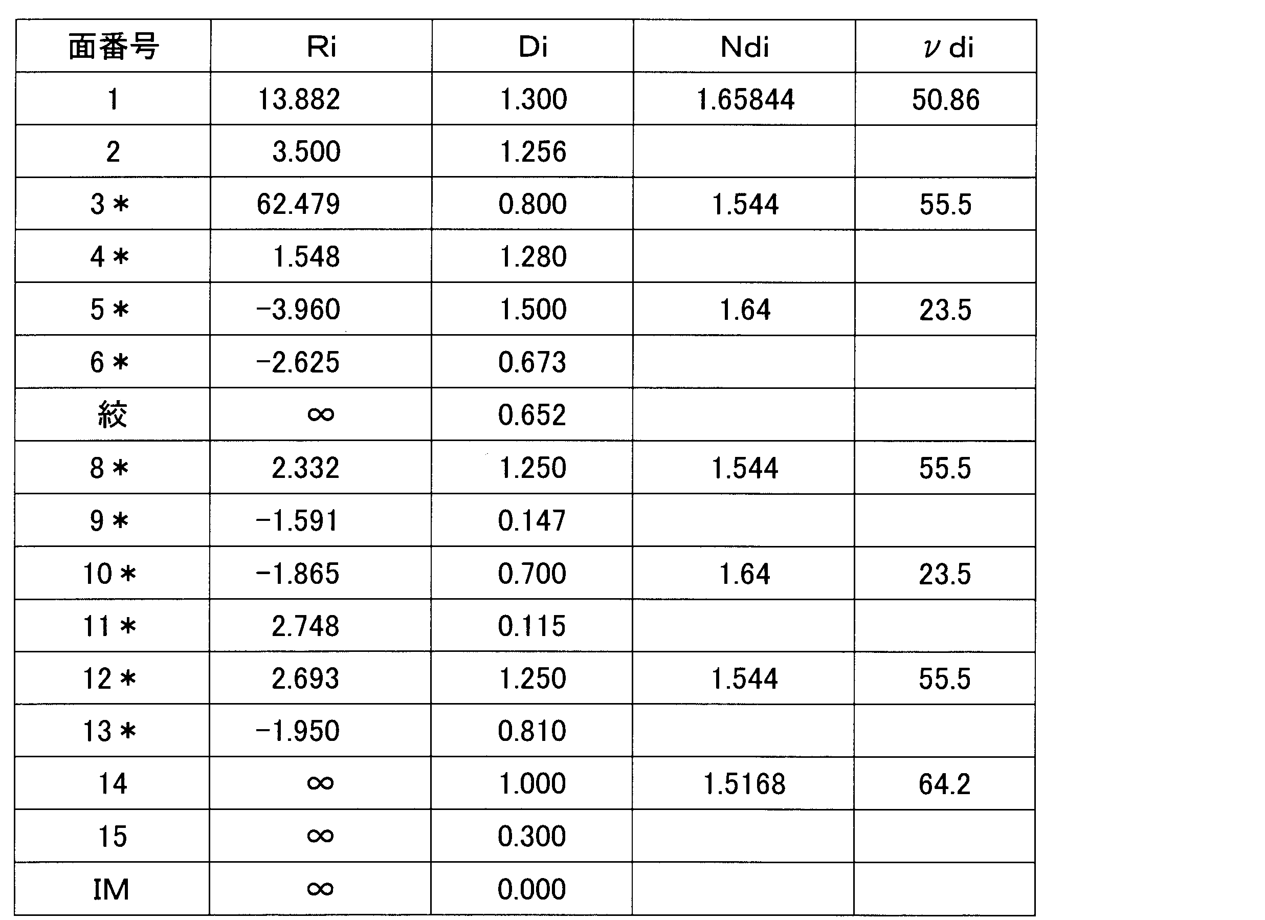
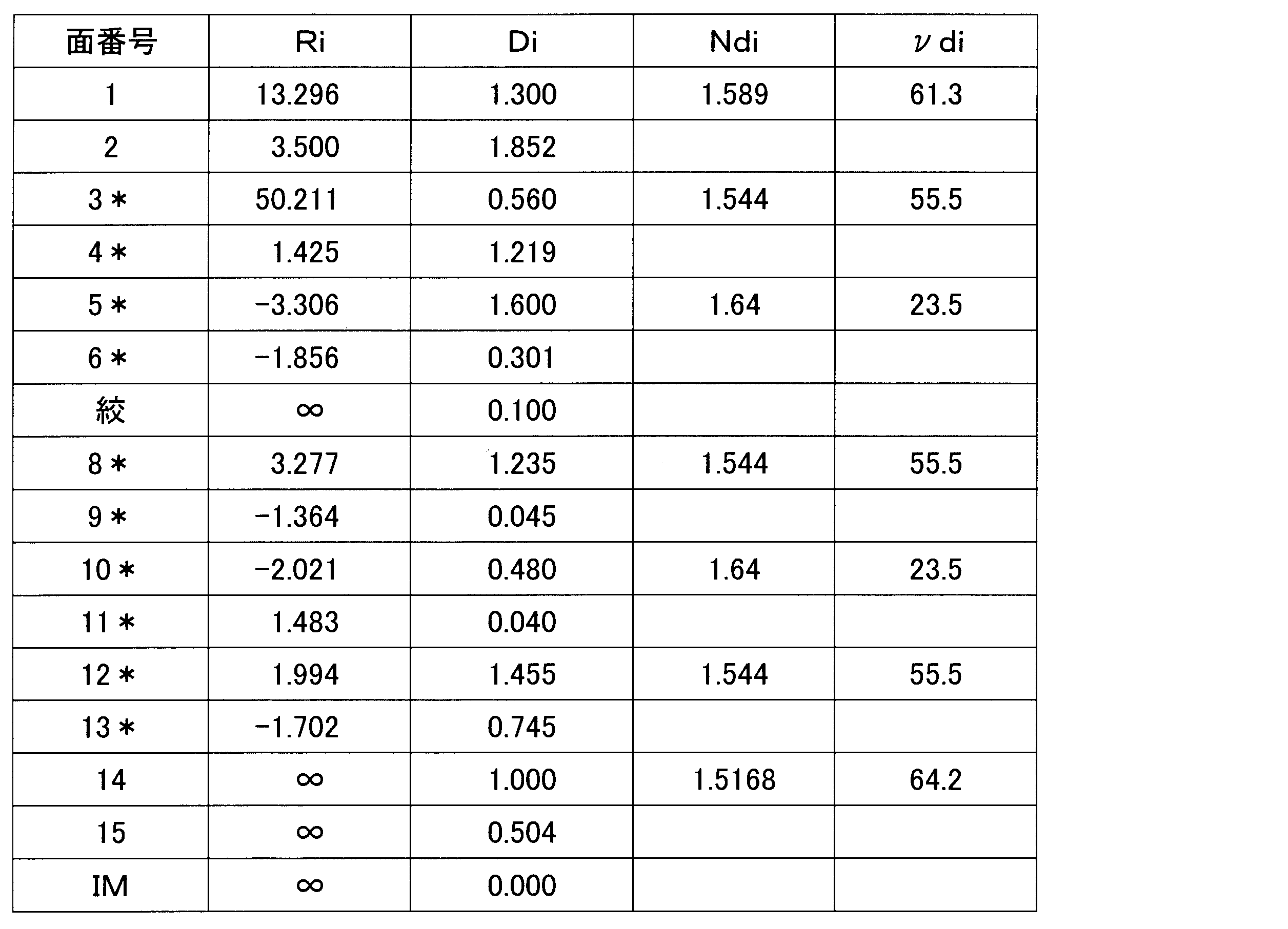
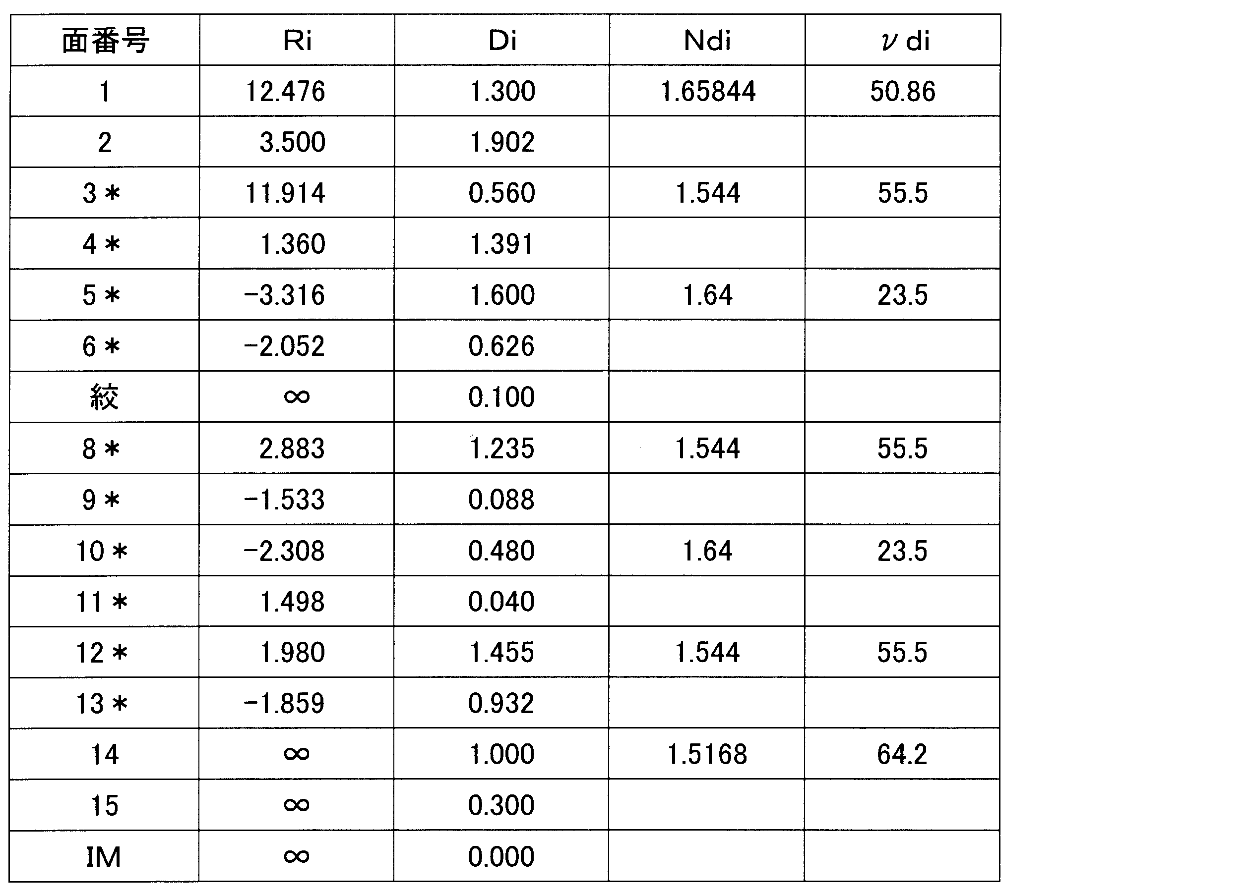
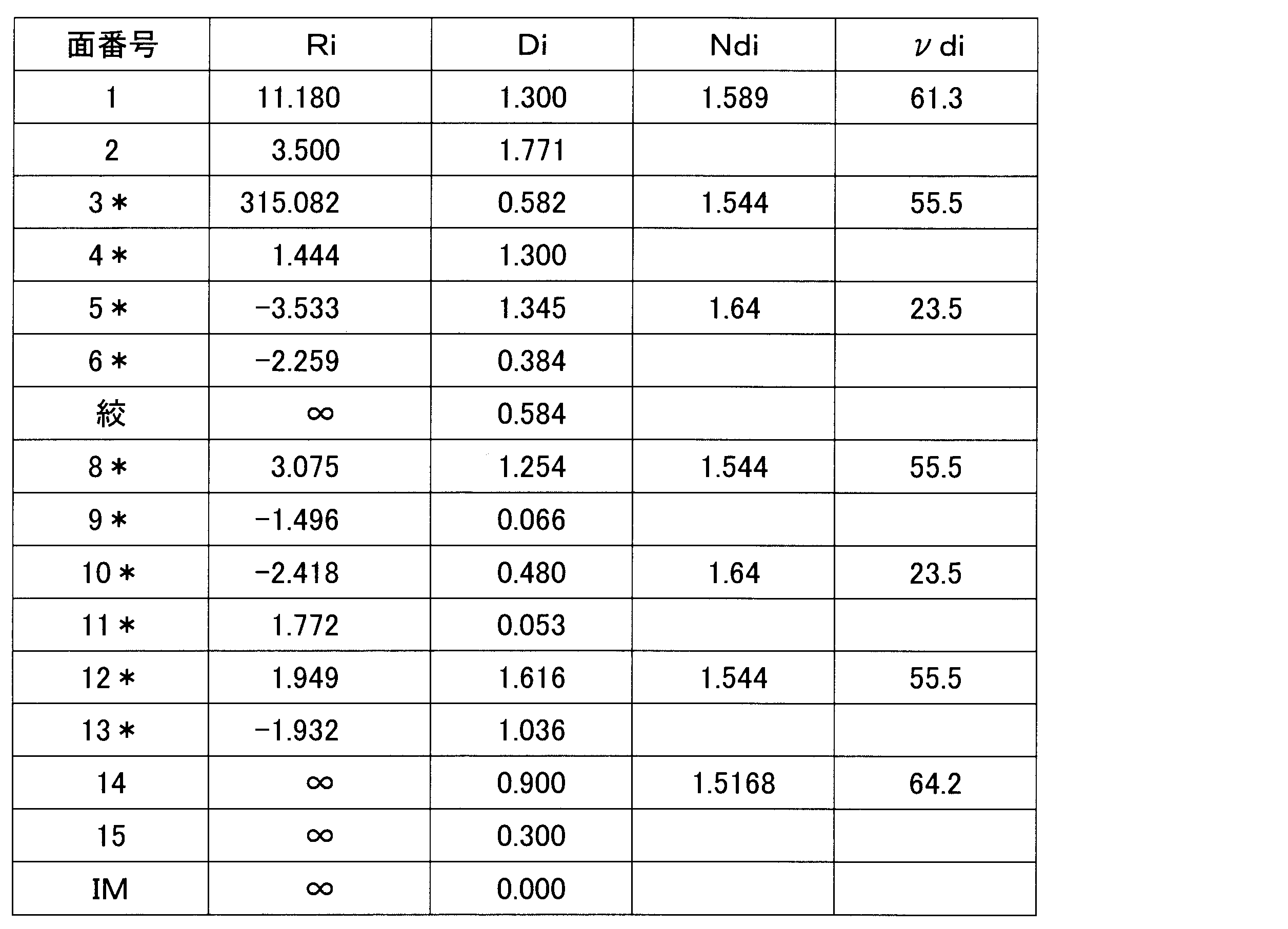
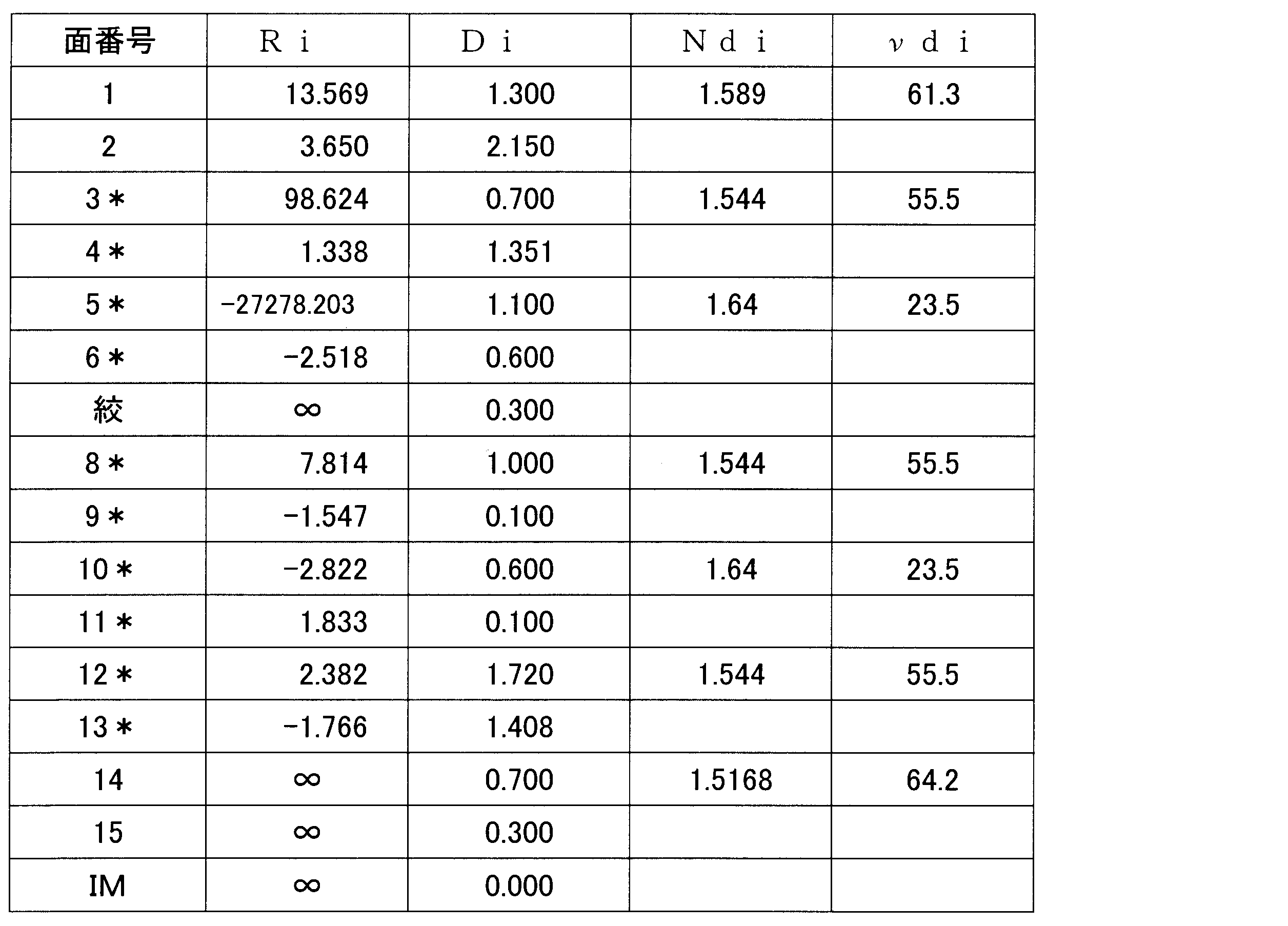
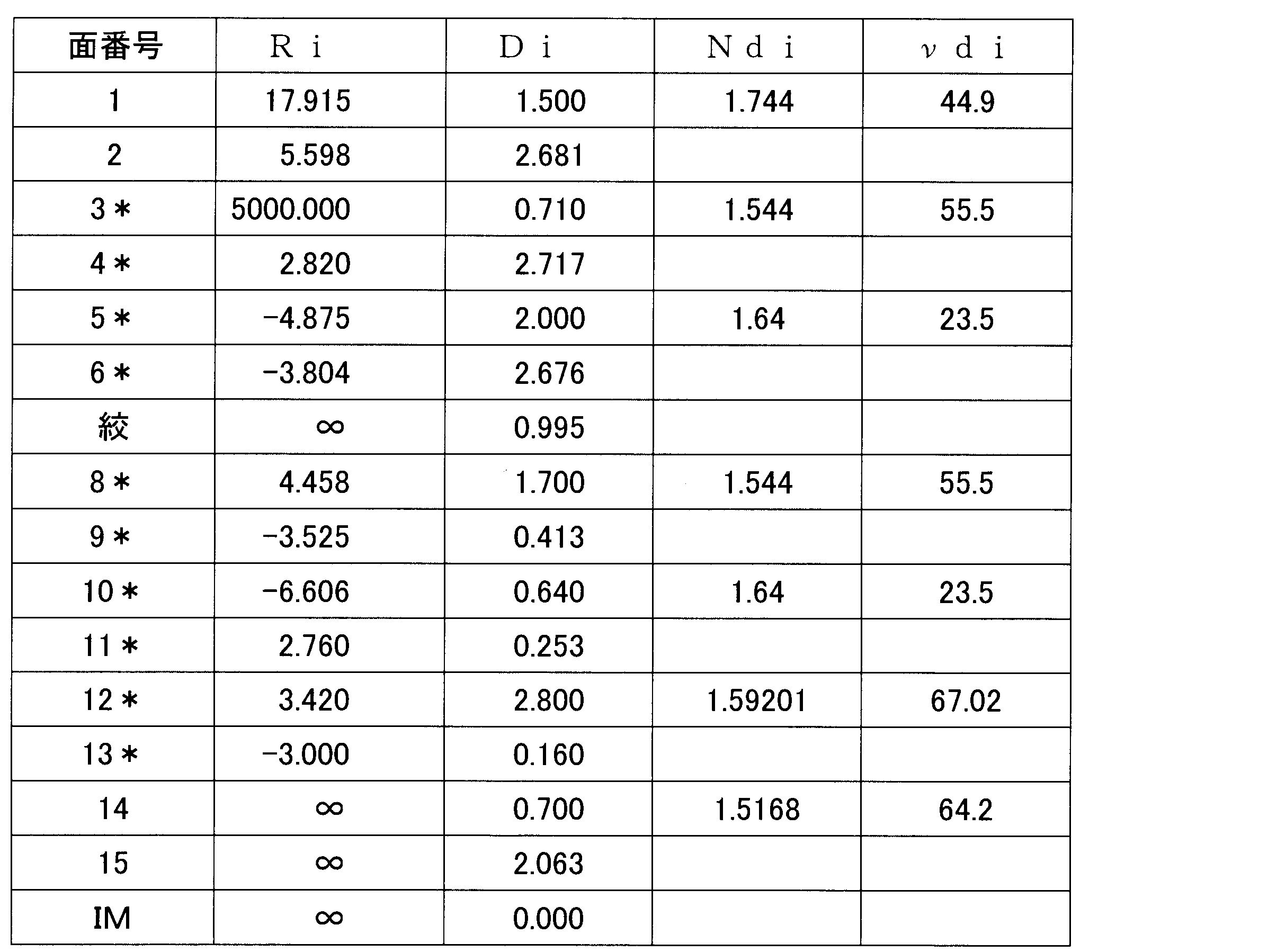
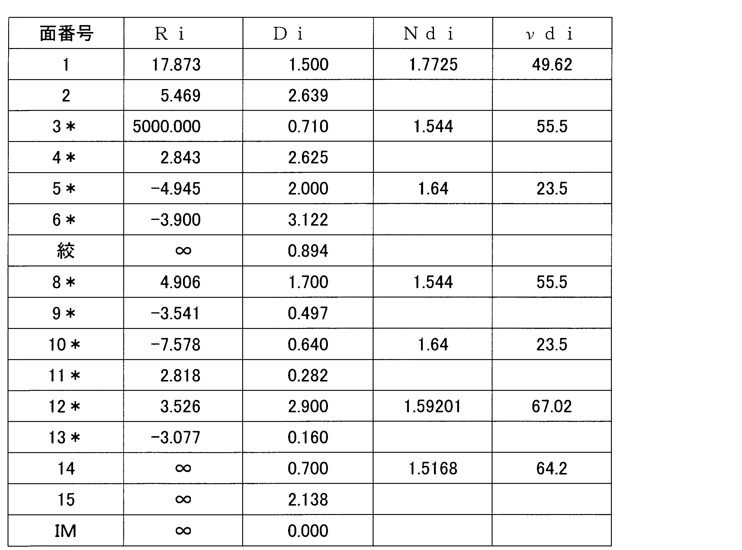
- “Surface number” indicates the number of the i-th surface counted from the object side to the image side.
- “Ri” indicates a value (mm) of a radius of curvature of the paraxial axis of the i-th surface, that is, on the optical axis.
- “Di” indicates a value (mm) of an axial upper surface interval (lens center thickness or air interval) between the i-th surface and the (i + 1) -th surface.
- “Ndi” indicates the value of the refractive index of the d-line (wavelength 587.56 nm) of a material such as a lens starting from the i-th surface.
- ⁇ di indicates the value of the Abbe number in the d-line of a material such as a lens starting from the i-th surface.
- the portion where the value of “Ri” is “ ⁇ ” indicates a flat surface or a diaphragm surface (aperture stop S).
- aperture stop S the surface described as “aperture” indicates the aperture stop S.
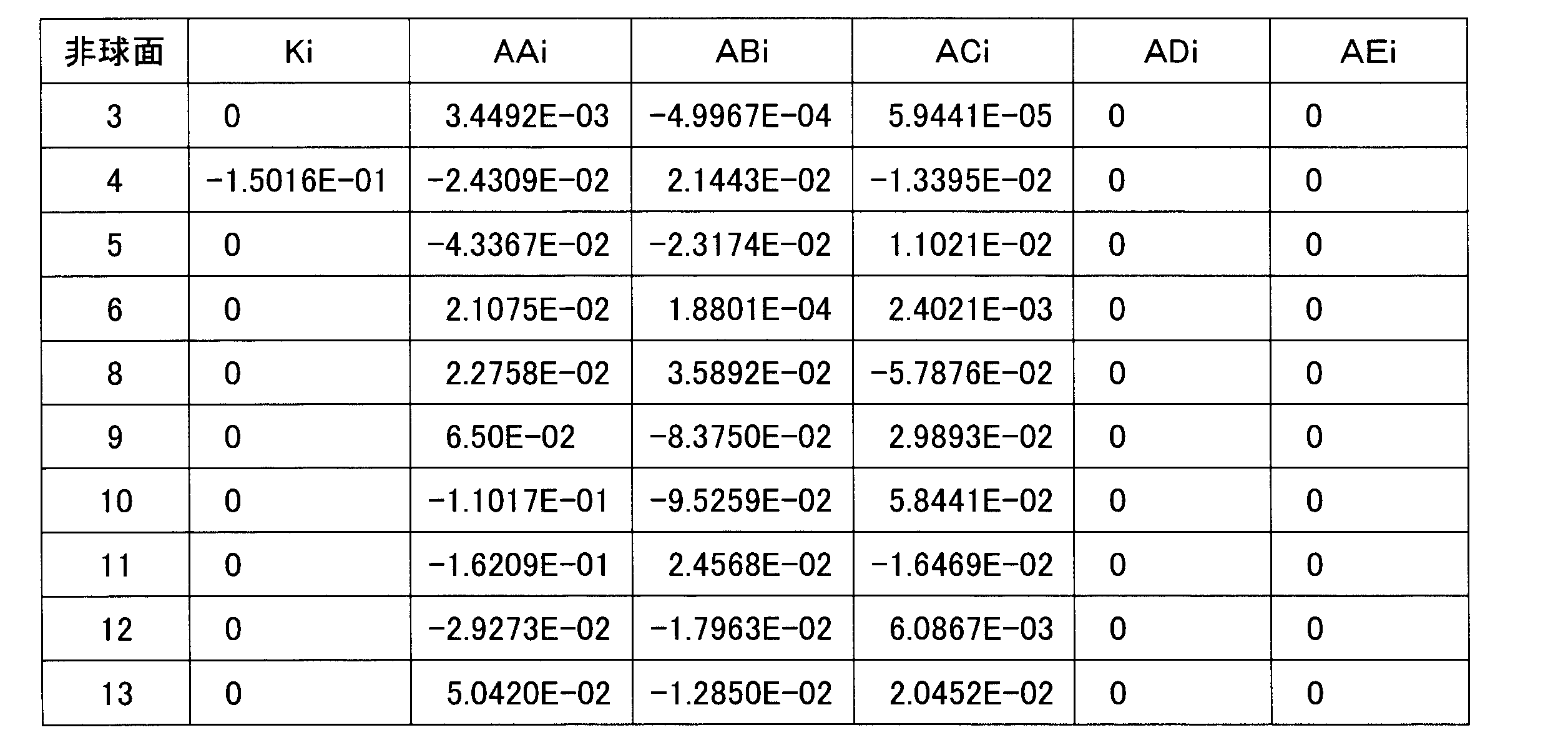
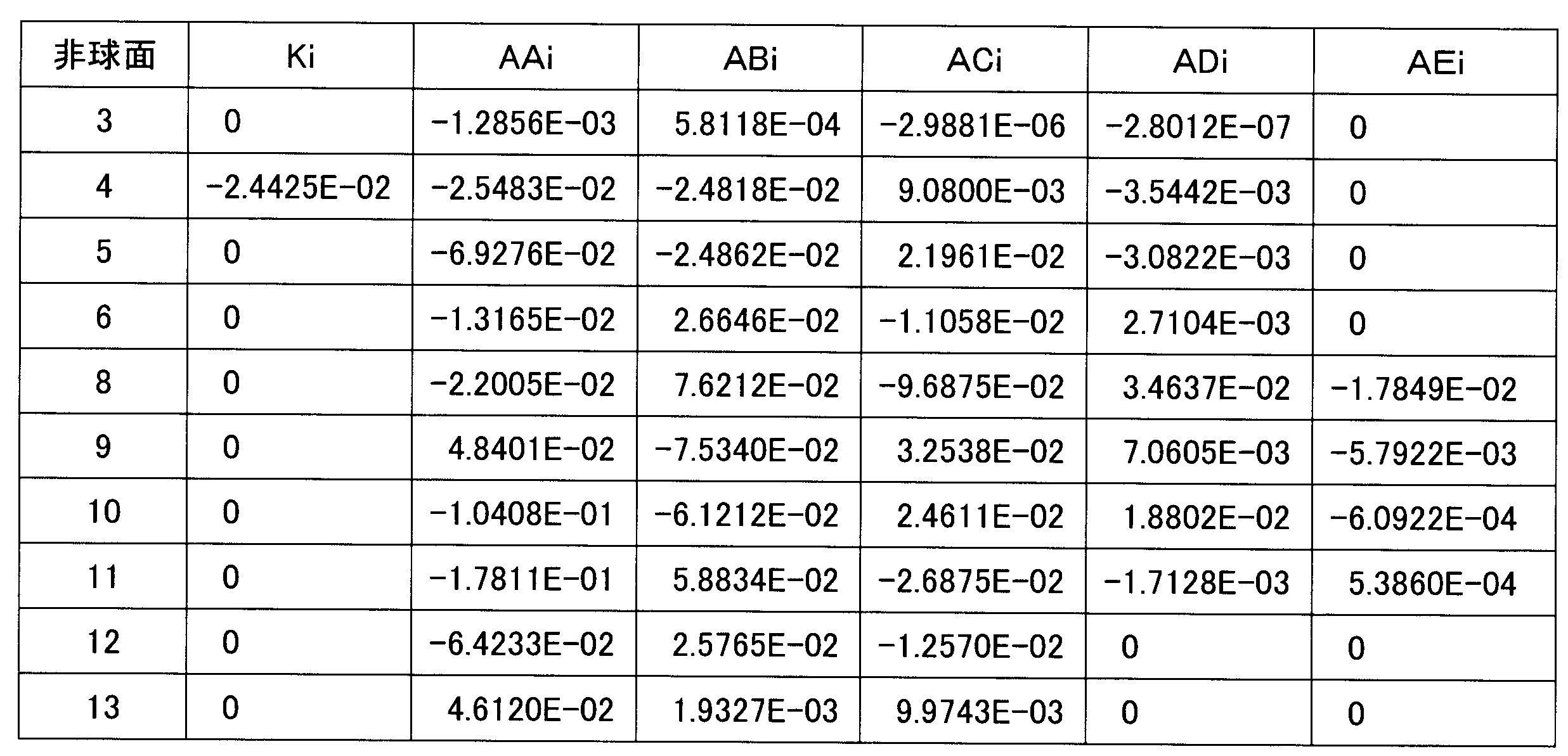
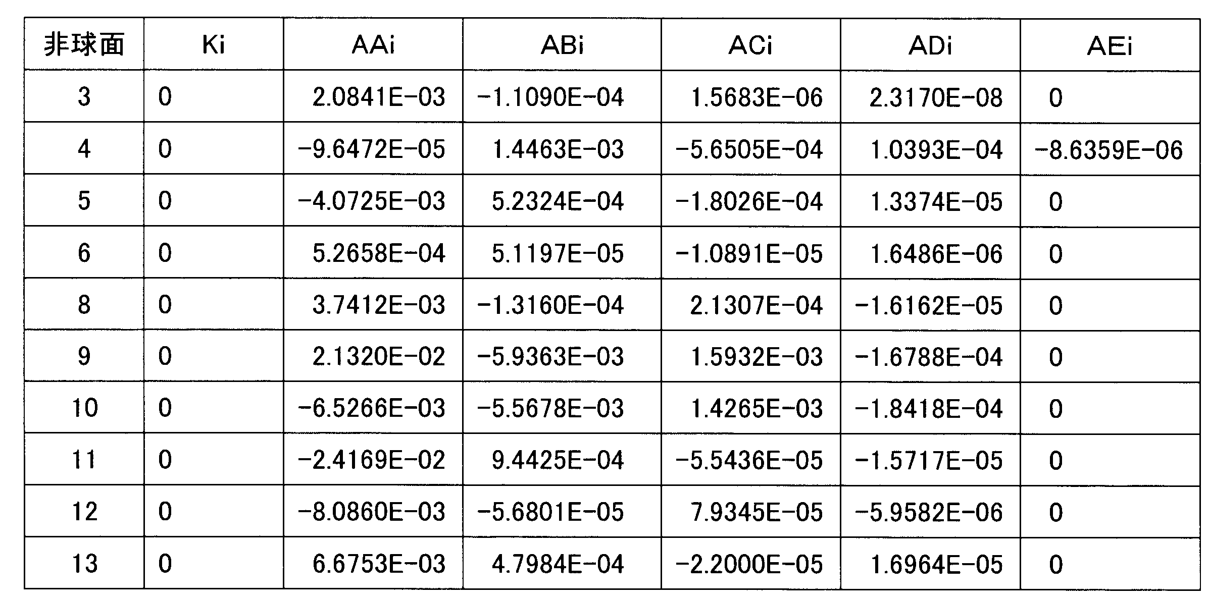
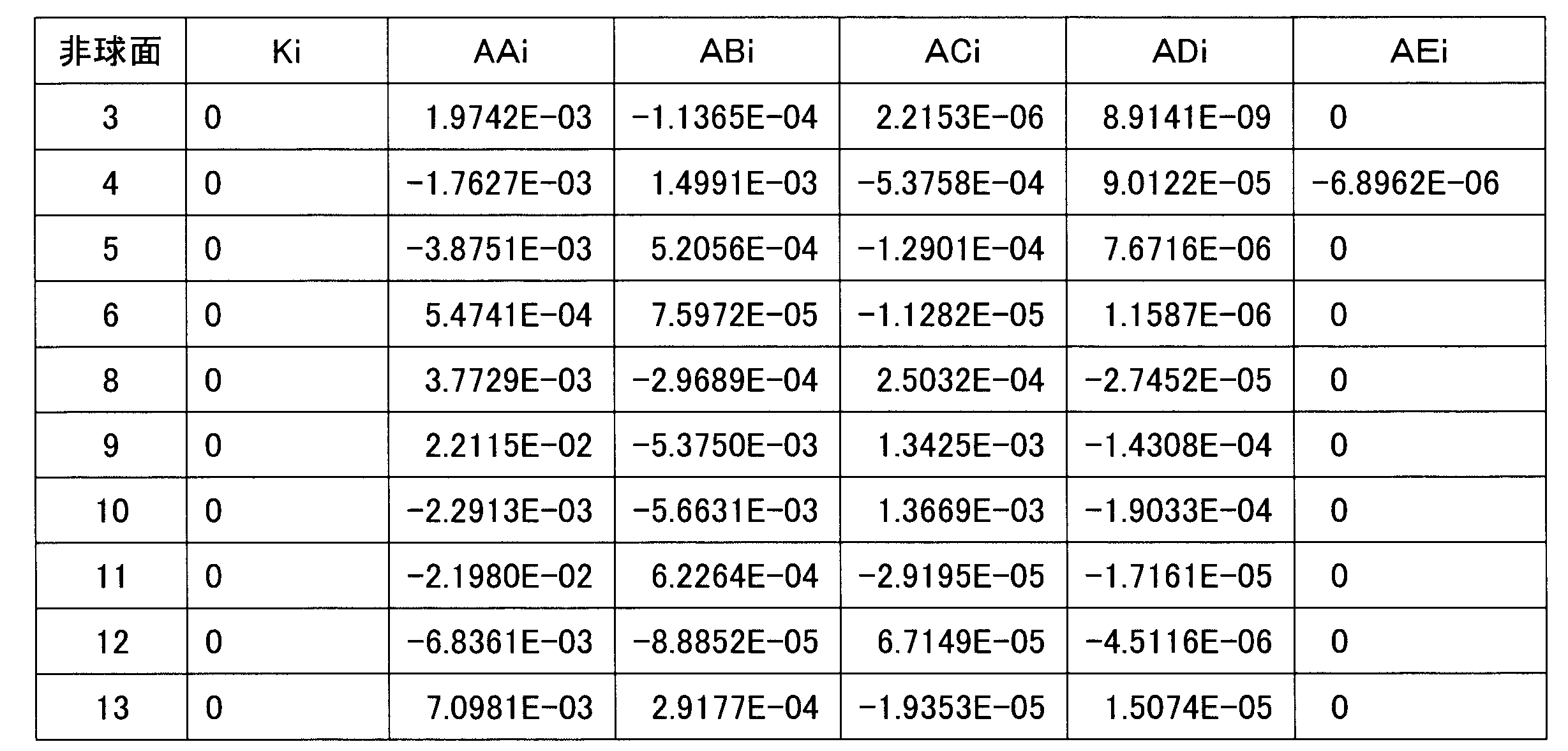
- Some lenses used in the numerical examples have an aspherical lens surface.
- the surface marked with “*” in “surface number” indicates that it is an aspherical surface.
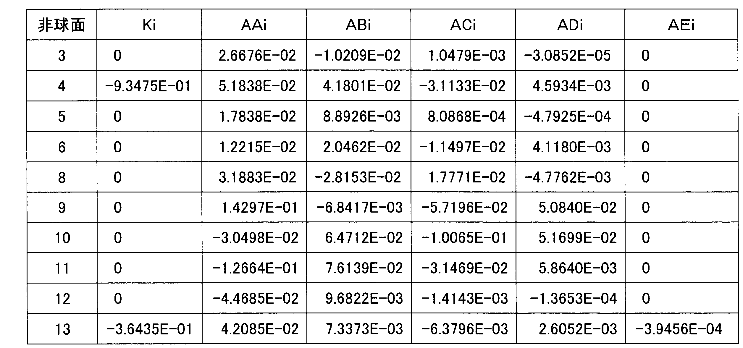
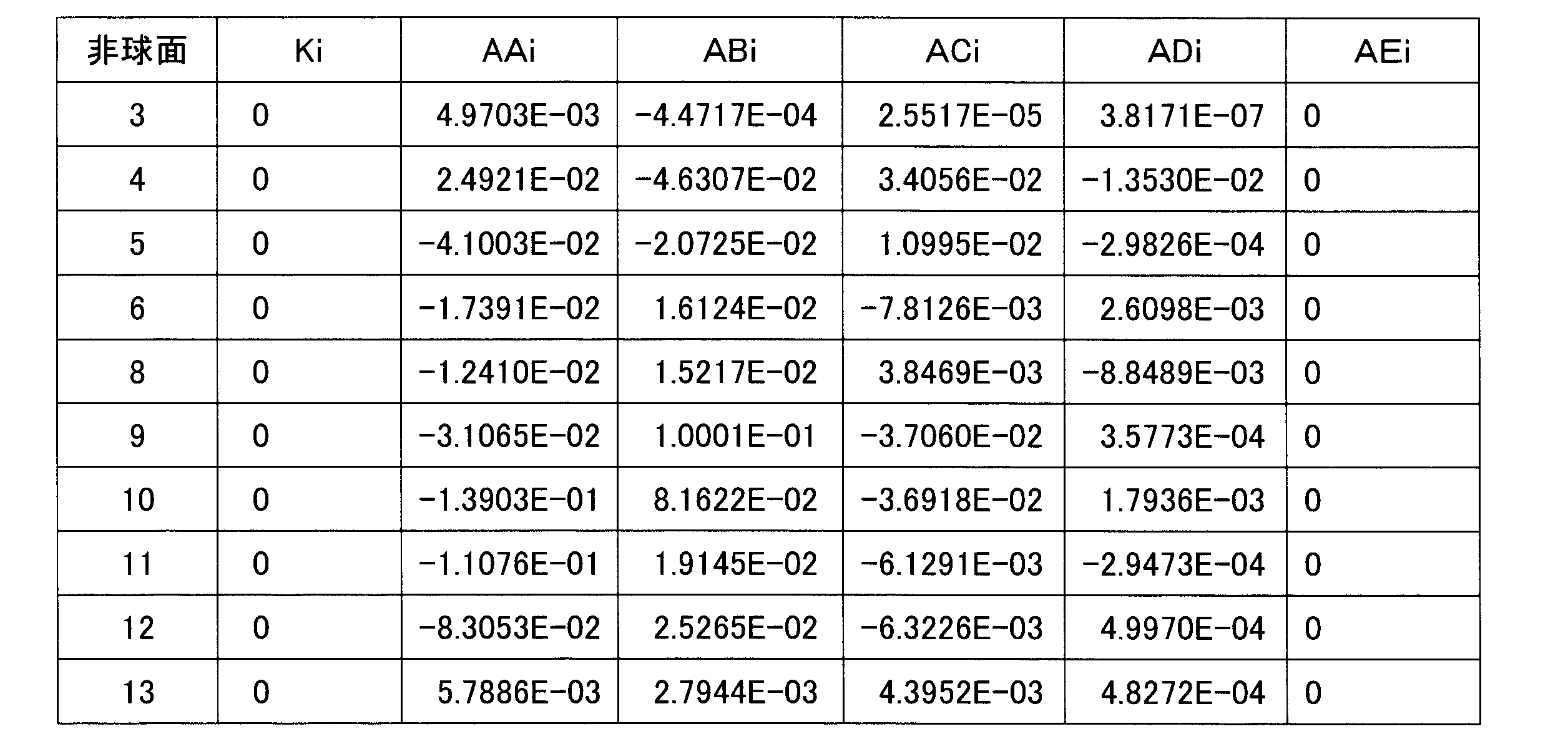
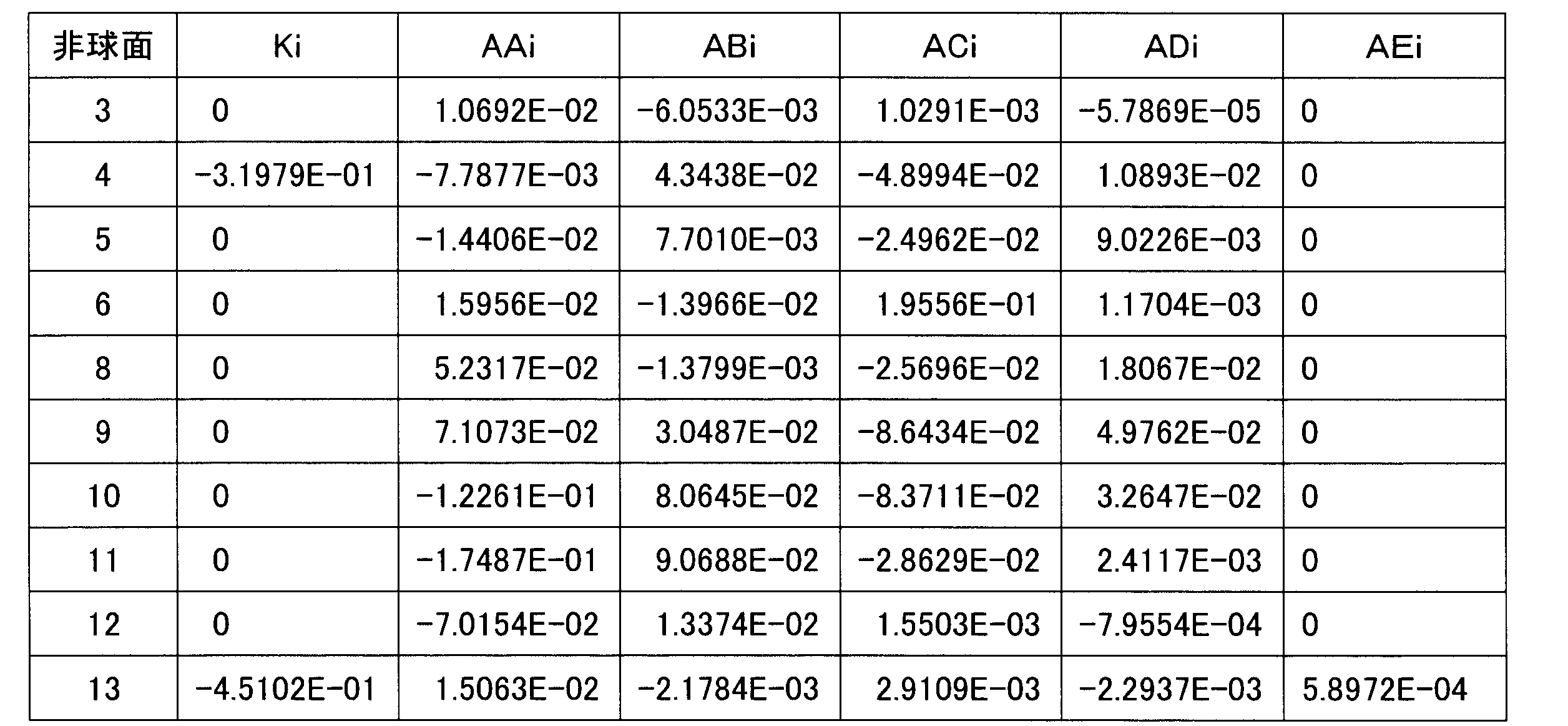
- the aspherical shape is defined by the following equation. In each table indicating the aspherical coefficient, “E ⁇ n” represents an exponential expression with a base of 10, that is, “10 to the negative n”, for example, “1.2345E-05” represents “1. 2345 ⁇ (10 to the fifth power) ”.
- the shape of the aspherical surface is expressed by the following formula.
- Z [(Y ⁇ 2 / R) / [1 + SQRT ⁇ 1- (1 + K) * (Y / R) ⁇ 2 ⁇ ] + AA * Y ⁇ 4 + AB * Y ⁇ 6 + AC * Y ⁇ 8 + AD * Y ⁇ 10 + AE * Y ⁇ 12
- the distance in the optical axis direction from the apex of the lens surface is “Z”, and the polarity is positive on the image surface side.
- the height in the direction perpendicular to the optical axis is “Y”, the radius of curvature of the surface on the optical axis is R, and the conic constant (conic constant) is “K”.
- AA”, “AB”, “AC”, “AD”, and “AE” indicate fourth-order, sixth-order, eighth-order, tenth-order, and twelfth-order aspheric coefficients, respectively.
- the imaging lenses 1 to 12 to which the following numerical examples are applied all have a total angle of view of 176 degrees or more, and have negative refractive power arranged in order from the object side to the image plane side.
- a biconvex sixth lens L6 having a positive refractive power passes through the parallel plate CG, and forms an image on the image plane IM.
- the first lens L1 is made of glass, and both surfaces are formed into spherical surfaces, and the second lens L2 to the fifth lens L5 are made of plastic.
- the sixth lens L6 is made of plastic in Numerical Examples 1 to 9, and made of glass in Numerical Examples 10 to 12, and both surfaces are aspherical.
- Table 1-1 shows the lens data of Numerical Example 1 in the imaging lens 1 shown in FIG. 1, and Table 1-2 shows the aspheric data.
- the total angle of view is 176 degrees, the F value is 2.05, and the focal length f of the entire imaging lens system is 1.048 mm.
- the lens data of Numerical Example 2 in the imaging lens 2 shown in FIG. 3 are shown in Table 2-1, and aspherical data are shown in Table 2-2.
- the total angle of view is 176 degrees, the F value is 2.05, and the focal length f of the entire imaging lens system is 1.042 mm.
- the lens data of Numerical Example 3 in the imaging lens 3 shown in FIG. 5 is shown in Table 3-1, and the aspherical data is shown in Table 3-2.
- the total angle of view is 176 degrees, the F value is 2.03, and the focal length f of the entire imaging lens system is 1.141 mm.
- FIG. 7 shows lens data of Numerical Example 4 in the imaging lens 4 shown in FIG. 7, and Table 4-2 shows aspheric data.
- the total angle of view is 210 degrees, the F value is 2.02, and the focal length f of the entire imaging lens system is 1.046 mm.
- the lens data of Numerical Example 5 in the imaging lens 5 shown in FIG. 9 is shown in Table 5-1, and the aspherical data is shown in Table 5-2.
- the total angle of view is 210 degrees, the F value is 2.02, and the focal length f of the entire imaging lens system is 1.050 mm.
- the lens data of Numerical Example 6 in the imaging lens 6 shown in FIG. 11 is shown in Table 6-1, and aspherical data is shown in Table 6-2.
- the total angle of view is 210 degrees, the F value is 2.02, and the focal length f of the entire imaging lens system is 1.061 mm.
- Table 7-1 shows lens data of Numerical Example 7 in the imaging lens 7 shown in FIG. 13, and Table 7-2 shows aspherical data.
- the total angle of view is 210 degrees, the F value is 2.05, and the focal length f of the entire imaging lens system is 1.045 mm.
- Table 8-1 shows lens data of Numerical Example 8 in the imaging lens 8 shown in FIG. 15, and Table 8-2 shows aspherical data.
- the total angle of view is 210 degrees, the F value is 2.05, and the focal length f of the entire imaging lens system is 1.061 mm.
- the lens data of Numerical Example 9 in the imaging lens 9 shown in FIG. 17 is shown in Table 9-1 and aspherical data is shown in Table 9-2.
- the total angle of view is 176 degrees
- the F value is 2.03
- the focal length f of the entire imaging lens system is 1.216 mm.
- the lens data of Numerical Example 10 in the imaging lens 10 shown in FIG. 19 are shown in Table 10-1, and aspherical data are shown in Table 10-2.
- the total angle of view is 206 degrees, the F value is 1.46, and the focal length f of the entire imaging lens system is 1.388 mm.
- the lens data of Numerical Example 11 in the imaging lens 11 shown in FIG. 21 is shown in Table 11-1, and aspherical data is shown in Table 11-2.
- the total angle of view is 206 degrees, the F value is 1.47, and the focal length f of the entire imaging lens system is 1.377 mm.
- Lens data of Numerical Example 12 in the imaging lens 12 shown in FIG. 23 is shown in Table 12-1, and aspherical data is shown in Table 12-2.
- the total angle of view is 206 degrees, the F value is 1.43, and the focal length f of the entire imaging lens system is 1.407 mm.
- Table 13 shows the main specifications of Numerical Example 1 to Numerical Example 12 and the values of conditional expressions (1) to (11).
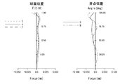
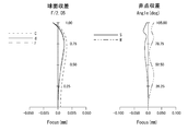
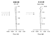
- FIGS. Point aberration is shown.
- the short dotted line in spherical aberration indicates the C line (656.27 nm)
- the solid line indicates the d line (587.56 nm)
- the long dotted line indicates the F line (486.13 nm)
- the solid line in astigmatism indicates The d-line sagittal image plane and the broken line.
- FIG. 25 shows an installation example 1 for in-vehicle use
- FIG. 26 shows an installation example 2.
- Installation example 1 for in-vehicle use is an installation example in which an image of 360 degrees around the vehicle 11 is obtained by four cameras each using an imaging lens.
- a camera 21 on the front, a camera 22 on the side, a camera 23 on the side, and a camera 24 on the back are installed, and an image captured by the cameras 21, 22, 23, and 24 is synthesized to obtain a 360-degree image.
- the imaging lens it is desirable to use a lens having a specification with a total angle of view of 200 degrees or more and a horizontal total field angle of 180 degrees or more.
- Installation example 2 for in-vehicle use is an installation example in which a rear image of the vehicle 11 is obtained by a single camera using an imaging lens.
- the camera 25 is installed behind.
- the imaging lens it is desirable to use a lens having a specification with a total angle of view of 150 degrees to 190 degrees and a horizontal angle of view of 120 degrees to 160 degrees.
- the lens configuration of the imaging lens of the present technology is substantially six lens configurations of the first lens L1 to the sixth lens L6.
- the present technology may be configured as follows.
- a meniscus first lens having negative refractive power and having a convex surface facing the object side
- a meniscus second lens having negative refractive power and having a convex surface facing the object side
- a third lens having a meniscus shape having a positive refractive power and a concave surface facing the object side
- An aperture stop A fourth lens having a positive refractive power and a biconvex shape
- a fifth lens having negative refractive power and a biconcave shape
- a biconvex sixth lens having positive refractive power, It consists of 6 elements in 6 groups with 6 independent lenses as a whole.
- the total angle of view is set to 150 degrees or more, An imaging lens that satisfies the following conditional expression (1), conditional expression (2), and conditional expression (3).
- ⁇ d1 Abbe number Nd1 at the d-line of the first lens
- Nd1 Refractive index f456 at the d-line of the first lens f456: Combined focal length of the fourth lens, fifth lens, and sixth lens f: The focal length of the entire system.
- ⁇ 4> The imaging lens according to any one of ⁇ 1> to ⁇ 3>, wherein the following conditional expression (6) is satisfied.
- (6) 0.1 ⁇ (R8 + R9) / (R8 ⁇ R9) ⁇ 0.8
- R8 radius of curvature on the optical axis of the object side surface of the fourth lens
- R9 radius of curvature on the optical axis of the image side surface of the fourth lens.
- ⁇ 5> The imaging lens according to any one of ⁇ 1> to ⁇ 4>, wherein the following conditional expression (7) is satisfied. (7) -2.3 ⁇ f5 / f ⁇ -1.1 However, f5: focal length of the fifth lens f: focal length of the entire system.
- a meniscus first lens having negative refractive power and having a convex surface facing the object side
- a meniscus second lens having negative refractive power and having a convex surface facing the object side
- a third lens having a meniscus shape having a positive refractive power and a concave surface facing the object side
- An aperture stop A fourth lens having a positive refractive power and a biconvex shape
- a fifth lens having negative refractive power and a biconcave shape
- a biconvex sixth lens having positive refractive power, It consists of 6 elements in 6 groups with 6 independent lenses as a whole.
- the total angle of view is set to 150 degrees or more, An imaging lens that satisfies the following conditional expression (1), conditional expression (2), and conditional expression (8).
- ⁇ d1 Abbe number Nd1 at the d-line of the first lens
- Nd1 Refractive index R1 at the d-line of the first lens
- R1 Radius of curvature on the optical axis of the object side surface of the first lens f: Focal length of the entire system.
- ⁇ 9> The imaging lens according to any one of ⁇ 6> to ⁇ 8>, wherein the following conditional expression (6) is satisfied. (6) 0.1 ⁇ (R8 + R9) / (R8 ⁇ R9) ⁇ 0.8 However, R8: radius of curvature on the optical axis of the object side surface of the fourth lens R9: radius of curvature on the optical axis of the image side surface of the fourth lens.
- a meniscus first lens having negative refractive power and having a convex surface facing the object side
- a meniscus second lens having negative refractive power and having a convex surface facing the object side
- a third lens having a meniscus shape having a positive refractive power and a concave surface facing the object side
- An aperture stop A fourth lens having a positive refractive power and a biconvex shape
- a fifth lens having negative refractive power and a biconcave shape
- a biconvex sixth lens having positive refractive power, It consists of 6 elements in 6 groups with 6 independent lenses as a whole.
- the total angle of view is set to 150 degrees or more, An imaging lens that satisfies the following conditional expression (1), conditional expression (2), and conditional expression (9).
- ⁇ d1 Abbe number Nd1 at the d-line of the first lens
- Nd1 Refractive index L at the d-line of the first lens
- L Distance from the vertex on the optical axis of the object-side surface of the first lens to the image plane
- f Focal point of the entire system Distance.
- ⁇ 15> The imaging lens according to any one of ⁇ 11> to ⁇ 14>, wherein the following conditional expression (7) is satisfied. (7) -2.3 ⁇ f5 / f ⁇ -1.1 However, f5: focal length of the fifth lens f: focal length of the entire system.
- a meniscus first lens having negative refractive power and having a convex surface facing the object side
- a meniscus second lens having negative refractive power and having a convex surface facing the object side
- a third lens having a meniscus shape having a positive refractive power and a concave surface facing the object side
- An aperture stop A fourth lens having a positive refractive power and a biconvex shape
- a fifth lens having negative refractive power and a biconcave shape
- a biconvex sixth lens having positive refractive power, It consists of 6 elements in 6 groups with 6 independent lenses as a whole.
- the total angle of view is set to 150 degrees or more
- An imaging lens that satisfies the following conditional expression (10). (10) 1.77 ⁇ f6 / f ⁇ 2.415
- f6 Focal length of the sixth lens
- f The focal length of the entire system.
- ⁇ 20> The imaging lens according to any one of ⁇ 16> to ⁇ 19>, wherein the following conditional expression (7) is satisfied. (7) -2.3 ⁇ f5 / f ⁇ -1.1 However, f5: focal length of the fifth lens f: focal length of the entire system.
- a meniscus first lens having negative refractive power and having a convex surface facing the object side
- a meniscus second lens having negative refractive power and having a convex surface facing the object side
- a third lens having a meniscus shape having a positive refractive power and a concave surface facing the object side
- An aperture stop A fourth lens having a positive refractive power and a biconvex shape
- a fifth lens having negative refractive power and a biconcave shape
- a biconvex sixth lens having positive refractive power, It consists of 6 elements in 6 groups with 6 independent lenses as a whole.
- the total angle of view is set to 150 degrees or more, An imaging lens that satisfies the following conditional expression (11). (11) 1.75 ⁇ R12 / f ⁇ 2.7 However, R12: radius of curvature on the optical axis of the object side surface of the sixth lens f: the focal length of the entire system.
- ⁇ 25> The imaging lens according to any one of ⁇ 21> to ⁇ 24>, wherein the following conditional expression (7) is satisfied. (7) -2.3 ⁇ f5 / f ⁇ -1.1 However, f5: focal length of the fifth lens f: focal length of the entire system.
- SYMBOLS 1 ... Imaging lens, 2 ... Imaging lens, 3 ... Imaging lens, 4 ... Imaging lens, 5 ... Imaging lens, 6 ... Imaging lens, 7 ... Imaging lens, 9 ... Imaging lens, 9 ... Imaging lens, 10 ... Imaging lens, DESCRIPTION OF SYMBOLS 11 ... Imaging lens, 12 ... Imaging lens, L1 ... 1st lens, L2 ... 2nd lens, L3 ... 3rd lens, L4 ... 4th lens, L5 ... 5th lens, L6 ... 6th lens, S ... Aperture stop CG ... Parallel plate, IM ... Image plane, Z ... Optical axis
Abstract
Description
(1)44<νd1
(2)Nd1<1.78
(3)2.505<f456/f<3.5
但し、
νd1:第1レンズのd線におけるアッベ数
Nd1:第1レンズのd線における屈折率
f456:第4レンズ、第5レンズ、第6レンズの合成焦点距離
f:全系の焦点距離
とする。 The first imaging lens according to the present technology includes a meniscus first lens having negative refractive power and a convex surface facing the object side, which is arranged in order from the object side to the image plane side, and negative refraction A second meniscus lens having a convex surface facing the object side, a third meniscus lens having a positive refractive power and a concave surface facing the object side, an aperture stop, and a positive refractive power And a biconvex fourth lens having negative refractive power, a biconcave fifth lens having negative refractive power, and a biconvex sixth lens having positive refractive power. It is composed of 6 elements in 6 groups with independent lenses, and the total angle of view is 150 degrees or more, which satisfies the following conditional expressions (1), (2) and (3).
(1) 44 <νd1
(2) Nd1 <1.78
(3) 2.505 <f456 / f <3.5
However,
νd1: Abbe number Nd1 at the d-line of the first lens Nd1: Refractive index f456 at the d-line of the first lens f456: Combined focal length of the fourth lens, fifth lens, and sixth lens f: The focal length of the entire system.
(1)44<νd1
(2)Nd1<1.78
(8)10.5<R1/f<16
但し、
νd1:第1レンズのd線におけるアッベ数
Nd1:第1レンズのd線における屈折率
R1:第1レンズの物体側の面の光軸上の曲率半径
f:全系の焦点距離
とする。 The second imaging lens according to the present technology includes a first meniscus lens having negative refractive power and a convex surface facing the object side, which is arranged in order from the object side to the image plane side, and negative refraction A second meniscus lens having a convex surface facing the object side, a third meniscus lens having a positive refractive power and a concave surface facing the object side, an aperture stop, and a positive refractive power And a biconvex fourth lens having negative refractive power, a biconcave fifth lens having negative refractive power, and a biconvex sixth lens having positive refractive power. Consists of 6 elements in 6 groups with independent lenses, the total angle of view is 150 degrees or more, and the following conditional expression (1), conditional expression (2) and conditional expression (8) are satisfied.
(1) 44 <νd1
(2) Nd1 <1.78
(8) 10.5 <R1 / f <16
However,
νd1: Abbe number Nd1 at the d-line of the first lens Nd1: Refractive index R1 at the d-line of the first lens R1: Radius of curvature on the optical axis of the object side surface of the first lens f: Focal length of the entire system.
(1)44<νd1
(2)Nd1<1.78
(9)10.7<L/f<16.5
但し、
νd1:第1レンズのd線におけるアッベ数
Nd1:第1レンズのd線における屈折率
L:第1レンズの物体側の面の光軸上の頂点から像面までの距離
f:全系の焦点距離
とする。 The third imaging lens according to the present technology includes a first meniscus lens having negative refractive power and a convex surface facing the object side, which is arranged in order from the object side to the image plane side, and negative refraction A second meniscus lens having a convex surface facing the object side, a third meniscus lens having a positive refractive power and a concave surface facing the object side, an aperture stop, and a positive refractive power And a biconvex fourth lens having negative refractive power, a biconcave fifth lens having negative refractive power, and a biconvex sixth lens having positive refractive power. It is composed of 6 groups of 6 elements with independent lenses, and has a total angle of view of 150 degrees or more, which satisfies the following conditional expressions (1), (2) and (9).
(1) 44 <νd1
(2) Nd1 <1.78
(9) 10.7 <L / f <16.5
However,
νd1: Abbe number Nd1 at the d-line of the first lens Nd1: Refractive index L at the d-line of the first lens L: Distance from the vertex on the optical axis of the object-side surface of the first lens to the image plane f: Focal point of the entire system Distance.
(10)1.77<f6/f<2.415
但し、
f6:第6レンズの焦点距離
f:全系の焦点距離
とする。 A fourth imaging lens according to the present technology includes a first meniscus lens having negative refractive power and a convex surface facing the object side, which is arranged in order from the object side to the image plane side, and negative refraction A second meniscus lens having a convex surface facing the object side, a third meniscus lens having a positive refractive power and a concave surface facing the object side, an aperture stop, and a positive refractive power And a biconvex fourth lens having negative refractive power, a biconcave fifth lens having negative refractive power, and a biconvex sixth lens having positive refractive power. It is composed of 6 elements in 6 groups with independent lenses, and the total angle of view is 150 degrees or more, which satisfies the following conditional expression (10).
(10) 1.77 <f6 / f <2.415
However,
f6: Focal length of the sixth lens f: The focal length of the entire system.
(11)1.75<R12/f<2.7
但し、
R12:第6レンズの物体側の面の光軸上の曲率半径
f:全系の焦点距離
とする。 A fifth imaging lens according to the present technology includes a first meniscus lens having negative refractive power and a convex surface facing the object side, which is arranged in order from the object side to the image plane side, and negative refraction A second meniscus lens having a convex surface facing the object side, a third meniscus lens having a positive refractive power and a concave surface facing the object side, an aperture stop, and a positive refractive power And a biconvex fourth lens having negative refractive power, a biconcave fifth lens having negative refractive power, and a biconvex sixth lens having positive refractive power. Consists of 6 elements in 6 groups with independent lenses, the total angle of view is 150 degrees or more, and the following conditional expression (11) is satisfied.
(11) 1.75 <R12 / f <2.7
However,
R12: radius of curvature on the optical axis of the object side surface of the sixth lens f: the focal length of the entire system.
(4)-0.25<(R10+R11)/(R10-R11)<0.6
(5)-4<R6/f<-1
(6)0.1<(R8+R9)/(R8-R9)<0.8
(7)-2.3<f5/f<-1.1
但し、
R10:第5レンズの物体側の面の光軸上の曲率半径
R11:第5レンズの像側の面の光軸上の曲率半径
R6:第3レンズの像側の面の光軸上の曲率半径
f:全系の焦点距離
R8:第4レンズの物体側の面の光軸上の曲率半径
R9:第4レンズの像側の面の光軸上の曲率半径
f5:第5レンズの焦点距離
とする。 In the imaging lens according to the present technology, it is preferable that at least one of the following conditional expressions (4), (5), (6), and (7) is satisfied. As a form, any of independent and combination may be sufficient.
(4) -0.25 <(R10 + R11) / (R10-R11) <0.6
(5) -4 <R6 / f <-1
(6) 0.1 <(R8 + R9) / (R8−R9) <0.8
(7) -2.3 <f5 / f <-1.1
However,
R10: radius of curvature on the optical axis of the object side surface of the fifth lens R11: radius of curvature on the optical axis of the image side surface of the fifth lens R6: curvature on the optical axis of the image side surface of the third lens Radius f: focal length of the entire system R8: radius of curvature on the optical axis of the object side surface of the fourth lens R9: radius of curvature on the optical axis of the image side surface of the fourth lens f5: focal length of the fifth lens And
以下に、本技術の実施形態に係る撮像レンズについて図面を参照して説明する。尚、本技術においては、凸面、凹面と言ったレンズ形状、正の屈折力、負の屈折力と言ったレンズの屈折力の符号は、近軸領域で定義されるものである。また、曲率半径も近軸領域で定義されるものであり、極性は、物体側に凸の面を正、像側に凸の面を負とする。さらに、各レンズ、合成、全系の焦点距離は、波長としてd線の587.56nmでの値で定義する。 [Imaging Lens according to Embodiment of Present Technology]
Hereinafter, an imaging lens according to an embodiment of the present technology will be described with reference to the drawings. In the present technology, the sign of the lens shape such as convex surface and concave surface, the refractive power of the lens such as positive refractive power and negative refractive power is defined in the paraxial region. The radius of curvature is also defined in the paraxial region, and the polarity is positive for the convex surface on the object side and negative for the convex surface on the image side. Further, the focal length of each lens, the synthesis, and the entire system is defined as a value at 587.56 nm of the d-line as a wavelength.
(1)44<νd1
(2)Nd1<1.78
(3)2.505<f456/f<3.5
(8)10.5<R1/f<16
(9)10.7<L/f<16.5
(10)1.77<f6/f<2.415
(11)1.75<R12/f<2.7
但し、
νd1:第1レンズのd線におけるアッベ数
Nd1:第1レンズのd線における屈折率
f456:第4レンズ、第5レンズ、第6レンズの合成焦点距離
f:全系の焦点距離
R1:第1レンズの物体側の面の光軸上の曲率半径
L:第1レンズの物体側の面の光軸上の頂点から像面までの距離
f6:第6レンズの焦点距離
R12:第6レンズの物体側の面の光軸上の曲率半径
とする。 The imaging lens of the present technology may include all of conditional expression (1), conditional expression (2), and conditional expression (3), or conditional expression (1), conditional expression (2), and conditional expression (8), or Conditional expression (1), conditional expression (2), and conditional expression (9) are all satisfied, or conditional expression (10) or conditional expression (11) is satisfied.
(1) 44 <νd1
(2) Nd1 <1.78
(3) 2.505 <f456 / f <3.5
(8) 10.5 <R1 / f <16
(9) 10.7 <L / f <16.5
(10) 1.77 <f6 / f <2.415
(11) 1.75 <R12 / f <2.7
However,
νd1: Abbe number at the d-line of the first lens Nd1: Refractive index at the d-line of the first lens f456: Combined focal length of the fourth lens, fifth lens, and sixth lens f: Focal length R1 of the entire system R1: First Radius of curvature L on the optical axis of the object-side surface of the lens: Distance from the vertex on the optical axis of the object-side surface of the first lens to the image plane f6: Focal length of the sixth lens R12: Object of the sixth lens The radius of curvature on the optical axis of the side surface.
(3-1)2.505<f456/f<3.3
(9-1)11<L/f<16.5
(11-1)1.8<R12/f<2.6
但し、
f456:第4レンズ、第5レンズ、第6レンズの合成焦点距離
f:全系の焦点距離
L:第1レンズの物体側の面の光軸上の頂点から像面までの距離
R12:第6レンズの物体側の面の光軸上の曲率半径
とする。 In the imaging lens of the present technology, instead of conditional expression (3), conditional expression (9), and conditional expression (11), conditional expression (3-1), conditional expression (9-1), and conditional expression respectively. It may be configured to satisfy (11-1).
(3-1) 2.505 <f456 / f <3.3
(9-1) 11 <L / f <16.5
(11-1) 1.8 <R12 / f <2.6
However,
f456: Composite focal length of the fourth lens, fifth lens, and sixth lens f: Focal length of the entire system L: Distance from the vertex on the optical axis of the object side surface of the first lens to the image plane R12: Sixth The radius of curvature on the optical axis of the object side surface of the lens.
(4)-0.25<(R10+R11)/(R10-R11)<0.6
(5)-4<R6/f<-1
(6)0.1<(R8+R9)/(R8-R9)<0.8
(7)-2.3<f5/f<-1.1
但し、
R10:第5レンズの物体側の面の光軸上の曲率半径
R11:第5レンズの像側の面の光軸上の曲率半径
R6:第3レンズの像側の面の光軸上の曲率半径
f:全系の焦点距離
R8:第4レンズの物体側の面の光軸上の曲率半径
R9:第4レンズの像側の面の光軸上の曲率半径
f5:第5レンズの焦点距離
とする。 In the imaging lens according to the present technology, it is preferable that at least one of the following conditional expressions (4), (5), (6), and (7) is satisfied. As a form, any of independent and combination may be sufficient.
(4) -0.25 <(R10 + R11) / (R10-R11) <0.6
(5) -4 <R6 / f <-1
(6) 0.1 <(R8 + R9) / (R8−R9) <0.8
(7) -2.3 <f5 / f <-1.1
However,
R10: radius of curvature on the optical axis of the object side surface of the fifth lens R11: radius of curvature on the optical axis of the image side surface of the fifth lens R6: curvature on the optical axis of the image side surface of the third lens Radius f: focal length of the entire system R8: radius of curvature on the optical axis of the object side surface of the fourth lens R9: radius of curvature on the optical axis of the image side surface of the fourth lens f5: focal length of the fifth lens And
(4-1)-0.2<(R10+R11)/(R10-R11)<0.5
(5-1)-3.5<R6/f<-1.5
(6-1)0.115<(R8+R9)/(R8-R9)<0.75
但し、
R10:第5レンズの物体側の面の光軸上の曲率半径
R11:第5レンズの像側の面の光軸上の曲率半径
R6:第3レンズの像側の面の光軸上の曲率半径
f:全系の焦点距離
R8:第4レンズの物体側の面の光軸上の曲率半径
R9:第4レンズの像側の面の光軸上の曲率半径
とする。 Note that in the imaging lens of the present technology, instead of the conditional expression (4), the conditional expression (5), and the conditional expression (6), the conditional expression (4-1), the conditional expression (5-1), and the conditional expression respectively. It may be configured to satisfy (6-1).
(4-1) -0.2 <(R10 + R11) / (R10-R11) <0.5
(5-1) -3.5 <R6 / f <-1.5
(6-1) 0.115 <(R8 + R9) / (R8-R9) <0.75
However,
R10: radius of curvature on the optical axis of the object side surface of the fifth lens R11: radius of curvature on the optical axis of the image side surface of the fifth lens R6: curvature on the optical axis of the image side surface of the third lens Radius f: focal length of entire system R8: radius of curvature on optical axis of object side surface of fourth lens R9: radius of curvature on optical axis of image side surface of fourth lens.
本実施の形態に係る撮像レンズの具体的な数値実施例について説明する。ここでは、図1、図3、図5、図7、図9、図11、図13、図15、図17、図19、図21及び図23にそれぞれ示した各構成例の撮像レンズ1乃至撮像レンズ12に、具体的な数値を適用した数値実施例を説明する。 [Numerical example of imaging lens]
Specific numerical examples of the imaging lens according to the present embodiment will be described. Here, the
Z=[(Y^2/R)/[1+SQRT{1-(1+K)*(Y/R)^2}]+AA *Y^4+AB *Y^6+AC *Y^8+AD *Y^10+AE *Y^12
上記の非球面式において、レンズ面の頂点から光軸方向における距離を「Z」とし、極性は像面側を正とする。光軸と垂直な方向における高さを「Y」、面の光軸上の曲率半径をR、円錐定数(コーニック定数)を「K」とする。「AA」、「AB」、「AC」、「AD」、「AE」はそれぞれ4次、6次、8次、10次、12次の非球面係数を示す。 The shape of the aspherical surface is expressed by the following formula.
Z = [(Y ^ 2 / R) / [1 + SQRT {1- (1 + K) * (Y / R) ^ 2}] + AA * Y ^ 4 + AB * Y ^ 6 + AC * Y ^ 8 + AD * Y ^ 10 + AE * Y ^ 12
In the above aspheric formula, the distance in the optical axis direction from the apex of the lens surface is “Z”, and the polarity is positive on the image surface side. The height in the direction perpendicular to the optical axis is “Y”, the radius of curvature of the surface on the optical axis is R, and the conic constant (conic constant) is “K”. “AA”, “AB”, “AC”, “AD”, and “AE” indicate fourth-order, sixth-order, eighth-order, tenth-order, and twelfth-order aspheric coefficients, respectively.


車載用途としての設置例1を図25に、設置例2を図26に示す。 [Installation example for in-vehicle use]
FIG. 25 shows an installation example 1 for in-vehicle use, and FIG. 26 shows an installation example 2.
本技術撮像レンズにおいては、第1レンズL1乃至第6レンズL6に加えて屈折力を有さないレンズ等の他の光学要素が配置されていてもよい。この場合において、本技術撮像レンズのレンズ構成は第1レンズL1乃至第6レンズL6の実質的に6枚のレンズ構成にされる。 [Others]
In the imaging lens of the present technology, in addition to the first lens L1 to the sixth lens L6, other optical elements such as a lens having no refractive power may be disposed. In this case, the lens configuration of the imaging lens of the present technology is substantially six lens configurations of the first lens L1 to the sixth lens L6.
本技術は、以下の構成にすることもできる。 [Technology]
The present technology may be configured as follows.
物体側から像面側に向けて順に配列された、
負の屈折力を有し物体側に凸面を向けたメニスカス形状の第1レンズと、
負の屈折力を有し物体側に凸面を向けたメニスカス形状の第2レンズと、
正の屈折力を有し物体側に凹面を向けたメニスカス形状の第3レンズと、
開口絞りと、
正の屈折力を有し両凸形状の第4レンズと、
負の屈折力を有し両凹形状の第5レンズと、
正の屈折力を有し両凸形状の第6レンズとから成り、
全体として6枚の独立したレンズによる6群6枚で構成され、
全画角が150度以上にされ、
下記の条件式(1)、条件式(2)及び条件式(3)を満足する
撮像レンズ。
(1)44<νd1
(2)Nd1<1.78
(3)2.505<f456/f<3.5
但し、
νd1:第1レンズのd線におけるアッベ数
Nd1:第1レンズのd線における屈折率
f456:第4レンズ、第5レンズ、第6レンズの合成焦点距離
f:全系の焦点距離
とする。 <1>
Arranged in order from the object side to the image plane side,
A meniscus first lens having negative refractive power and having a convex surface facing the object side;
A meniscus second lens having negative refractive power and having a convex surface facing the object side;
A third lens having a meniscus shape having a positive refractive power and a concave surface facing the object side;
An aperture stop,
A fourth lens having a positive refractive power and a biconvex shape;
A fifth lens having negative refractive power and a biconcave shape;
A biconvex sixth lens having positive refractive power,
It consists of 6 elements in 6 groups with 6 independent lenses as a whole.
The total angle of view is set to 150 degrees or more,
An imaging lens that satisfies the following conditional expression (1), conditional expression (2), and conditional expression (3).
(1) 44 <νd1
(2) Nd1 <1.78
(3) 2.505 <f456 / f <3.5
However,
νd1: Abbe number Nd1 at the d-line of the first lens Nd1: Refractive index f456 at the d-line of the first lens f456: Combined focal length of the fourth lens, fifth lens, and sixth lens f: The focal length of the entire system.
下記の条件式(4)を満足する
前記<1>に記載の撮像レンズ。
(4)-0.25<(R10+R11)/(R10-R11)<0.6
但し、
R10:第5レンズの物体側の面の光軸上の曲率半径
R11:第5レンズの像側の面の光軸上の曲率半径
とする。 <2>
The imaging lens according to <1>, wherein the following conditional expression (4) is satisfied.
(4) -0.25 <(R10 + R11) / (R10-R11) <0.6
However,
R10: radius of curvature on the optical axis of the object side surface of the fifth lens R11: radius of curvature on the optical axis of the image side surface of the fifth lens.
下記の条件式(5)を満足する
前記<1>または前記<2>に記載の撮像レンズ。
(5)-4<R6/f<-1
但し、
R6:第3レンズの像側の面の光軸上の曲率半径
f:全系の焦点距離
とする。 <3>
The imaging lens according to <1> or <2>, wherein the following conditional expression (5) is satisfied.
(5) -4 <R6 / f <-1
However,
R6: radius of curvature on the optical axis of the image side surface of the third lens f: the focal length of the entire system.
下記の条件式(6)を満足する
前記<1>から前記<3>の何れかに記載の撮像レンズ。
(6)0.1<(R8+R9)/(R8-R9)<0.8
但し、
R8:第4レンズの物体側の面の光軸上の曲率半径
R9:第4レンズの像側の面の光軸上の曲率半径
とする。 <4>
The imaging lens according to any one of <1> to <3>, wherein the following conditional expression (6) is satisfied.
(6) 0.1 <(R8 + R9) / (R8−R9) <0.8
However,
R8: radius of curvature on the optical axis of the object side surface of the fourth lens R9: radius of curvature on the optical axis of the image side surface of the fourth lens.
下記の条件式(7)を満足する
前記<1>から前記<4>の何れかに記載の撮像レンズ。
(7)-2.3<f5/f<-1.1
但し、
f5:第5レンズの焦点距離
f:全系の焦点距離
とする。 <5>
The imaging lens according to any one of <1> to <4>, wherein the following conditional expression (7) is satisfied.
(7) -2.3 <f5 / f <-1.1
However,
f5: focal length of the fifth lens f: focal length of the entire system.
物体側から像面側に向けて順に配列された、
負の屈折力を有し物体側に凸面を向けたメニスカス形状の第1レンズと、
負の屈折力を有し物体側に凸面を向けたメニスカス形状の第2レンズと、
正の屈折力を有し物体側に凹面を向けたメニスカス形状の第3レンズと、
開口絞りと、
正の屈折力を有し両凸形状の第4レンズと、
負の屈折力を有し両凹形状の第5レンズと、
正の屈折力を有し両凸形状の第6レンズとから成り、
全体として6枚の独立したレンズによる6群6枚で構成され、
全画角が150度以上にされ、
下記の条件式(1)、条件式(2)及び条件式(8)を満足する
撮像レンズ。
(1)44<νd1
(2)Nd1<1.78
(8)10.5<R1/f<16
但し、
νd1:第1レンズのd線におけるアッベ数
Nd1:第1レンズのd線における屈折率
R1:第1レンズの物体側の面の光軸上の曲率半径
f:全系の焦点距離
とする。 <6>
Arranged in order from the object side to the image plane side,
A meniscus first lens having negative refractive power and having a convex surface facing the object side;
A meniscus second lens having negative refractive power and having a convex surface facing the object side;
A third lens having a meniscus shape having a positive refractive power and a concave surface facing the object side;
An aperture stop,
A fourth lens having a positive refractive power and a biconvex shape;
A fifth lens having negative refractive power and a biconcave shape;
A biconvex sixth lens having positive refractive power,
It consists of 6 elements in 6 groups with 6 independent lenses as a whole.
The total angle of view is set to 150 degrees or more,
An imaging lens that satisfies the following conditional expression (1), conditional expression (2), and conditional expression (8).
(1) 44 <νd1
(2) Nd1 <1.78
(8) 10.5 <R1 / f <16
However,
νd1: Abbe number Nd1 at the d-line of the first lens Nd1: Refractive index R1 at the d-line of the first lens R1: Radius of curvature on the optical axis of the object side surface of the first lens f: Focal length of the entire system.
下記の条件式(4)を満足する
前記<6>に記載の撮像レンズ。
(4)-0.25<(R10+R11)/(R10-R11)<0.6
但し、
R10:第5レンズの物体側の面の光軸上の曲率半径
R11:第5レンズの像側の面の光軸上の曲率半径
とする。 <7>
The imaging lens according to <6>, wherein the following conditional expression (4) is satisfied.
(4) -0.25 <(R10 + R11) / (R10-R11) <0.6
However,
R10: radius of curvature on the optical axis of the object side surface of the fifth lens R11: radius of curvature on the optical axis of the image side surface of the fifth lens.
下記の条件式(5)を満足する
前記<6>または前記<7>に記載の撮像レンズ。
(5)-4<R6/f<-1
但し、
R6:第3レンズの像側の面の光軸上の曲率半径
f:全系の焦点距離
とする。 <8>
The imaging lens according to <6> or <7>, wherein the following conditional expression (5) is satisfied.
(5) -4 <R6 / f <-1
However,
R6: radius of curvature on the optical axis of the image side surface of the third lens f: the focal length of the entire system.
下記の条件式(6)を満足する
前記<6>から前記<8>の何れかに記載の撮像レンズ。
(6)0.1<(R8+R9)/(R8-R9)<0.8
但し、
R8:第4レンズの物体側の面の光軸上の曲率半径
R9:第4レンズの像側の面の光軸上の曲率半径
とする。 <9>
The imaging lens according to any one of <6> to <8>, wherein the following conditional expression (6) is satisfied.
(6) 0.1 <(R8 + R9) / (R8−R9) <0.8
However,
R8: radius of curvature on the optical axis of the object side surface of the fourth lens R9: radius of curvature on the optical axis of the image side surface of the fourth lens.
下記の条件式(7)を満足する
前記<6>から前記<9>の何れかに記載の撮像レンズ。
(7)-2.3<f5/f<-1.1
但し、
f5:第5レンズの焦点距離
f:全系の焦点距離
とする。 <10>
The imaging lens according to any one of <6> to <9>, wherein the following conditional expression (7) is satisfied.
(7) -2.3 <f5 / f <-1.1
However,
f5: focal length of the fifth lens f: focal length of the entire system.
物体側から像面側に向けて順に配列された、
負の屈折力を有し物体側に凸面を向けたメニスカス形状の第1レンズと、
負の屈折力を有し物体側に凸面を向けたメニスカス形状の第2レンズと、
正の屈折力を有し物体側に凹面を向けたメニスカス形状の第3レンズと、
開口絞りと、
正の屈折力を有し両凸形状の第4レンズと、
負の屈折力を有し両凹形状の第5レンズと、
正の屈折力を有し両凸形状の第6レンズとから成り、
全体として6枚の独立したレンズによる6群6枚で構成され、
全画角が150度以上にされ、
下記の条件式(1)、条件式(2)及び条件式(9)を満足する
撮像レンズ。
(1)44<νd1
(2)Nd1<1.78
(9)10.7<L/f<16.5
但し、
νd1:第1レンズのd線におけるアッベ数
Nd1:第1レンズのd線における屈折率
L:第1レンズの物体側の面の光軸上の頂点から像面までの距離
f:全系の焦点距離
とする。 <11>
Arranged in order from the object side to the image plane side,
A meniscus first lens having negative refractive power and having a convex surface facing the object side;
A meniscus second lens having negative refractive power and having a convex surface facing the object side;
A third lens having a meniscus shape having a positive refractive power and a concave surface facing the object side;
An aperture stop,
A fourth lens having a positive refractive power and a biconvex shape;
A fifth lens having negative refractive power and a biconcave shape;
A biconvex sixth lens having positive refractive power,
It consists of 6 elements in 6 groups with 6 independent lenses as a whole.
The total angle of view is set to 150 degrees or more,
An imaging lens that satisfies the following conditional expression (1), conditional expression (2), and conditional expression (9).
(1) 44 <νd1
(2) Nd1 <1.78
(9) 10.7 <L / f <16.5
However,
νd1: Abbe number Nd1 at the d-line of the first lens Nd1: Refractive index L at the d-line of the first lens L: Distance from the vertex on the optical axis of the object-side surface of the first lens to the image plane f: Focal point of the entire system Distance.
下記の条件式(4)を満足する
前記<11>に記載の撮像レンズ。
(4)-0.25<(R10+R11)/(R10-R11)<0.6
但し、
R10:第5レンズの物体側の面の光軸上の曲率半径
R11:第5レンズの像側の面の光軸上の曲率半径
とする。 <12>
The imaging lens according to <11>, wherein the following conditional expression (4) is satisfied.
(4) -0.25 <(R10 + R11) / (R10-R11) <0.6
However,
R10: radius of curvature on the optical axis of the object side surface of the fifth lens R11: radius of curvature on the optical axis of the image side surface of the fifth lens.
下記の条件式(5)を満足する
前記<11>または前記<12>に記載の撮像レンズ。
(5)-4<R6/f<-1
但し、
R6:第3レンズの像側の面の光軸上の曲率半径
f:全系の焦点距離
とする。 <13>
The imaging lens according to <11> or <12>, wherein the following conditional expression (5) is satisfied.
(5) -4 <R6 / f <-1
However,
R6: radius of curvature on the optical axis of the image side surface of the third lens f: the focal length of the entire system.
下記の条件式(6)を満足する
前記<11>から前記<13>の何れかに記載の撮像レンズ。
(6)0.1<(R8+R9)/(R8-R9)<0.8
但し、
R8:第4レンズの物体側の面の光軸上の曲率半径
R9:第4レンズの像側の面の光軸上の曲率半径
とする。 <14>
The imaging lens according to any one of <11> to <13>, wherein the following conditional expression (6) is satisfied.
(6) 0.1 <(R8 + R9) / (R8−R9) <0.8
However,
R8: radius of curvature on the optical axis of the object side surface of the fourth lens R9: radius of curvature on the optical axis of the image side surface of the fourth lens.
下記の条件式(7)を満足する
前記<11>から前記<14>の何れかに記載の撮像レンズ。
(7)-2.3<f5/f<-1.1
但し、
f5:第5レンズの焦点距離
f:全系の焦点距離
とする。 <15>
The imaging lens according to any one of <11> to <14>, wherein the following conditional expression (7) is satisfied.
(7) -2.3 <f5 / f <-1.1
However,
f5: focal length of the fifth lens f: focal length of the entire system.
物体側から像面側に向けて順に配列された、
負の屈折力を有し物体側に凸面を向けたメニスカス形状の第1レンズと、
負の屈折力を有し物体側に凸面を向けたメニスカス形状の第2レンズと、
正の屈折力を有し物体側に凹面を向けたメニスカス形状の第3レンズと、
開口絞りと、
正の屈折力を有し両凸形状の第4レンズと、
負の屈折力を有し両凹形状の第5レンズと、
正の屈折力を有し両凸形状の第6レンズとから成り、
全体として6枚の独立したレンズによる6群6枚で構成され、
全画角が150度以上にされ、
下記の条件式(10)を満足する
撮像レンズ。
(10)1.77<f6/f<2.415
但し、
f6:第6レンズの焦点距離
f:全系の焦点距離
とする。 <16>
Arranged in order from the object side to the image plane side,
A meniscus first lens having negative refractive power and having a convex surface facing the object side;
A meniscus second lens having negative refractive power and having a convex surface facing the object side;
A third lens having a meniscus shape having a positive refractive power and a concave surface facing the object side;
An aperture stop,
A fourth lens having a positive refractive power and a biconvex shape;
A fifth lens having negative refractive power and a biconcave shape;
A biconvex sixth lens having positive refractive power,
It consists of 6 elements in 6 groups with 6 independent lenses as a whole.
The total angle of view is set to 150 degrees or more,
An imaging lens that satisfies the following conditional expression (10).
(10) 1.77 <f6 / f <2.415
However,
f6: Focal length of the sixth lens f: The focal length of the entire system.
下記の条件式(4)を満足する
前記<16>に記載の撮像レンズ。
(4)-0.25<(R10+R11)/(R10-R11)<0.6
但し、
R10:第5レンズの物体側の面の光軸上の曲率半径
R11:第5レンズの像側の面の光軸上の曲率半径
とする。 <17>
The imaging lens according to <16>, wherein the following conditional expression (4) is satisfied.
(4) -0.25 <(R10 + R11) / (R10-R11) <0.6
However,
R10: radius of curvature on the optical axis of the object side surface of the fifth lens R11: radius of curvature on the optical axis of the image side surface of the fifth lens.
下記の条件式(5)を満足する
前記<16>または前記<17>に記載の撮像レンズ。
(5)-4<R6/f<-1
但し、
R6:第3レンズの像側の面の光軸上の曲率半径
f:全系の焦点距離
とする。 <18>
The imaging lens according to <16> or <17>, wherein the following conditional expression (5) is satisfied.
(5) -4 <R6 / f <-1
However,
R6: radius of curvature on the optical axis of the image side surface of the third lens f: the focal length of the entire system.
下記の条件式(6)を満足する
前記<16>から前記<18>の何れかに記載の撮像レンズ。
(6)0.1<(R8+R9)/(R8-R9)<0.8
但し、
R8:第4レンズの物体側の面の光軸上の曲率半径
R9:第4レンズの像側の面の光軸上の曲率半径
とする。 <19>
The imaging lens according to any one of <16> to <18>, wherein the following conditional expression (6) is satisfied.
(6) 0.1 <(R8 + R9) / (R8−R9) <0.8
However,
R8: radius of curvature on the optical axis of the object side surface of the fourth lens R9: radius of curvature on the optical axis of the image side surface of the fourth lens.
下記の条件式(7)を満足する
前記<16>から前記<19>の何れかに記載の撮像レンズ。
(7)-2.3<f5/f<-1.1
但し、
f5:第5レンズの焦点距離
f:全系の焦点距離
とする。 <20>
The imaging lens according to any one of <16> to <19>, wherein the following conditional expression (7) is satisfied.
(7) -2.3 <f5 / f <-1.1
However,
f5: focal length of the fifth lens f: focal length of the entire system.
物体側から像面側に向けて順に配列された、
負の屈折力を有し物体側に凸面を向けたメニスカス形状の第1レンズと、
負の屈折力を有し物体側に凸面を向けたメニスカス形状の第2レンズと、
正の屈折力を有し物体側に凹面を向けたメニスカス形状の第3レンズと、
開口絞りと、
正の屈折力を有し両凸形状の第4レンズと、
負の屈折力を有し両凹形状の第5レンズと、
正の屈折力を有し両凸形状の第6レンズとから成り、
全体として6枚の独立したレンズによる6群6枚で構成され、
全画角が150度以上にされ、
下記の条件式(11)を満足する
撮像レンズ。
(11)1.75<R12/f<2.7
但し、
R12:第6レンズの物体側の面の光軸上の曲率半径
f:全系の焦点距離
とする。 <21>
Arranged in order from the object side to the image plane side,
A meniscus first lens having negative refractive power and having a convex surface facing the object side;
A meniscus second lens having negative refractive power and having a convex surface facing the object side;
A third lens having a meniscus shape having a positive refractive power and a concave surface facing the object side;
An aperture stop,
A fourth lens having a positive refractive power and a biconvex shape;
A fifth lens having negative refractive power and a biconcave shape;
A biconvex sixth lens having positive refractive power,
It consists of 6 elements in 6 groups with 6 independent lenses as a whole.
The total angle of view is set to 150 degrees or more,
An imaging lens that satisfies the following conditional expression (11).
(11) 1.75 <R12 / f <2.7
However,
R12: radius of curvature on the optical axis of the object side surface of the sixth lens f: the focal length of the entire system.
下記の条件式(4)を満足する
前記<21>に記載の撮像レンズ。
(4)-0.25<(R10+R11)/(R10-R11)<0.6
但し、
R10:第5レンズの物体側の面の光軸上の曲率半径
R11:第5レンズの像側の面の光軸上の曲率半径
とする。 <22>
The imaging lens according to <21>, wherein the following conditional expression (4) is satisfied.
(4) -0.25 <(R10 + R11) / (R10-R11) <0.6
However,
R10: radius of curvature on the optical axis of the object side surface of the fifth lens R11: radius of curvature on the optical axis of the image side surface of the fifth lens.
下記の条件式(5)を満足する
前記<21>または前記<22>に記載の撮像レンズ。
(5)-4<R6/f<-1
但し、
R6:第3レンズの像側の面の光軸上の曲率半径
f:全系の焦点距離
とする。 <23>
The imaging lens according to <21> or <22>, wherein the following conditional expression (5) is satisfied.
(5) -4 <R6 / f <-1
However,
R6: radius of curvature on the optical axis of the image side surface of the third lens f: the focal length of the entire system.
下記の条件式(6)を満足する
前記<21>から前記<23>の何れかに記載の撮像レンズ。
(6)0.1<(R8+R9)/(R8-R9)<0.8
但し、
R8:第4レンズの物体側の面の光軸上の曲率半径
R9:第4レンズの像側の面の光軸上の曲率半径
とする。 <24>
The imaging lens according to any one of <21> to <23>, wherein the following conditional expression (6) is satisfied.
(6) 0.1 <(R8 + R9) / (R8−R9) <0.8
However,
R8: radius of curvature on the optical axis of the object side surface of the fourth lens R9: radius of curvature on the optical axis of the image side surface of the fourth lens.
下記の条件式(7)を満足する
前記<21>から前記<24>の何れかに記載の撮像レンズ。
(7)-2.3<f5/f<-1.1
但し、
f5:第5レンズの焦点距離
f:全系の焦点距離
とする。 <25>
The imaging lens according to any one of <21> to <24>, wherein the following conditional expression (7) is satisfied.
(7) -2.3 <f5 / f <-1.1
However,
f5: focal length of the fifth lens f: focal length of the entire system.
Claims (25)
- 物体側から像面側に向けて順に配列された、
負の屈折力を有し物体側に凸面を向けたメニスカス形状の第1レンズと、
負の屈折力を有し物体側に凸面を向けたメニスカス形状の第2レンズと、
正の屈折力を有し物体側に凹面を向けたメニスカス形状の第3レンズと、
開口絞りと、
正の屈折力を有し両凸形状の第4レンズと、
負の屈折力を有し両凹形状の第5レンズと、
正の屈折力を有し両凸形状の第6レンズとから成り、
全体として6枚の独立したレンズによる6群6枚で構成され、
全画角が150度以上にされ、
下記の条件式(1)、条件式(2)及び条件式(3)を満足する
撮像レンズ。
(1)44<νd1
(2)Nd1<1.78
(3)2.505<f456/f<3.5
但し、
νd1:第1レンズのd線におけるアッベ数
Nd1:第1レンズのd線における屈折率
f456:第4レンズ、第5レンズ、第6レンズの合成焦点距離
f:全系の焦点距離
とする。 Arranged in order from the object side to the image plane side,
A meniscus first lens having negative refractive power and having a convex surface facing the object side;
A meniscus second lens having negative refractive power and having a convex surface facing the object side;
A third lens having a meniscus shape having a positive refractive power and a concave surface facing the object side;
An aperture stop,
A fourth lens having a positive refractive power and a biconvex shape;
A fifth lens having negative refractive power and a biconcave shape;
A biconvex sixth lens having positive refractive power,
It consists of 6 elements in 6 groups with 6 independent lenses as a whole.
The total angle of view is set to 150 degrees or more,
An imaging lens that satisfies the following conditional expression (1), conditional expression (2), and conditional expression (3).
(1) 44 <νd1
(2) Nd1 <1.78
(3) 2.505 <f456 / f <3.5
However,
νd1: Abbe number Nd1 at the d-line of the first lens Nd1: Refractive index f456 at the d-line of the first lens f456: Combined focal length of the fourth lens, fifth lens, and sixth lens f: The focal length of the entire system. - 下記の条件式(4)を満足する
請求項1に記載の撮像レンズ。
(4)-0.25<(R10+R11)/(R10-R11)<0.6
但し、
R10:第5レンズの物体側の面の光軸上の曲率半径
R11:第5レンズの像側の面の光軸上の曲率半径
とする。 The imaging lens according to claim 1, wherein the following conditional expression (4) is satisfied.
(4) -0.25 <(R10 + R11) / (R10-R11) <0.6
However,
R10: radius of curvature on the optical axis of the object side surface of the fifth lens R11: radius of curvature on the optical axis of the image side surface of the fifth lens. - 下記の条件式(5)を満足する
請求項1に記載の撮像レンズ。
(5)-4<R6/f<-1
但し、
R6:第3レンズの像側の面の光軸上の曲率半径
f:全系の焦点距離
とする。 The imaging lens according to claim 1, wherein the following conditional expression (5) is satisfied.
(5) -4 <R6 / f <-1
However,
R6: radius of curvature on the optical axis of the image side surface of the third lens f: the focal length of the entire system. - 下記の条件式(6)を満足する
請求項1に記載の撮像レンズ。
(6)0.1<(R8+R9)/(R8-R9)<0.8
但し、
R8:第4レンズの物体側の面の光軸上の曲率半径
R9:第4レンズの像側の面の光軸上の曲率半径
とする。 The imaging lens according to claim 1, wherein the following conditional expression (6) is satisfied.
(6) 0.1 <(R8 + R9) / (R8−R9) <0.8
However,
R8: radius of curvature on the optical axis of the object side surface of the fourth lens R9: radius of curvature on the optical axis of the image side surface of the fourth lens. - 下記の条件式(7)を満足する
請求項1に記載の撮像レンズ。
(7)-2.3<f5/f<-1.1
但し、
f5:第5レンズの焦点距離
f:全系の焦点距離
とする。 The imaging lens according to claim 1, wherein the following conditional expression (7) is satisfied.
(7) -2.3 <f5 / f <-1.1
However,
f5: focal length of the fifth lens f: focal length of the entire system. - 物体側から像面側に向けて順に配列された、
負の屈折力を有し物体側に凸面を向けたメニスカス形状の第1レンズと、
負の屈折力を有し物体側に凸面を向けたメニスカス形状の第2レンズと、
正の屈折力を有し物体側に凹面を向けたメニスカス形状の第3レンズと、
開口絞りと、
正の屈折力を有し両凸形状の第4レンズと、
負の屈折力を有し両凹形状の第5レンズと、
正の屈折力を有し両凸形状の第6レンズとから成り、
全体として6枚の独立したレンズによる6群6枚で構成され、
全画角が150度以上にされ、
下記の条件式(1)、条件式(2)及び条件式(8)を満足する
撮像レンズ。
(1)44<νd1
(2)Nd1<1.78
(8)10.5<R1/f<16
但し、
νd1:第1レンズのd線におけるアッベ数
Nd1:第1レンズのd線における屈折率
R1:第1レンズの物体側の面の光軸上の曲率半径
f:全系の焦点距離
とする。 Arranged in order from the object side to the image plane side,
A meniscus first lens having negative refractive power and having a convex surface facing the object side;
A meniscus second lens having negative refractive power and having a convex surface facing the object side;
A third lens having a meniscus shape having a positive refractive power and a concave surface facing the object side;
An aperture stop,
A fourth lens having a positive refractive power and a biconvex shape;
A fifth lens having negative refractive power and a biconcave shape;
A biconvex sixth lens having positive refractive power,
It consists of 6 elements in 6 groups with 6 independent lenses as a whole.
The total angle of view is set to 150 degrees or more,
An imaging lens that satisfies the following conditional expression (1), conditional expression (2), and conditional expression (8).
(1) 44 <νd1
(2) Nd1 <1.78
(8) 10.5 <R1 / f <16
However,
νd1: Abbe number Nd1 at the d-line of the first lens Nd1: Refractive index R1 at the d-line of the first lens R1: Radius of curvature on the optical axis of the object side surface of the first lens f: Focal length of the entire system. - 下記の条件式(4)を満足する
請求項6に記載の撮像レンズ。
(4)-0.25<(R10+R11)/(R10-R11)<0.6
但し、
R10:第5レンズの物体側の面の光軸上の曲率半径
R11:第5レンズの像側の面の光軸上の曲率半径
とする。 The imaging lens according to claim 6, wherein the following conditional expression (4) is satisfied.
(4) -0.25 <(R10 + R11) / (R10-R11) <0.6
However,
R10: radius of curvature on the optical axis of the object side surface of the fifth lens R11: radius of curvature on the optical axis of the image side surface of the fifth lens. - 下記の条件式(5)を満足する
請求項6に記載の撮像レンズ。
(5)-4<R6/f<-1
但し、
R6:第3レンズの像側の面の光軸上の曲率半径
f:全系の焦点距離
とする。 The imaging lens according to claim 6, wherein the following conditional expression (5) is satisfied.
(5) -4 <R6 / f <-1
However,
R6: radius of curvature on the optical axis of the image side surface of the third lens f: the focal length of the entire system. - 下記の条件式(6)を満足する
請求項6に記載の撮像レンズ。
(6)0.1<(R8+R9)/(R8-R9)<0.8
但し、
R8:第4レンズの物体側の面の光軸上の曲率半径
R9:第4レンズの像側の面の光軸上の曲率半径
とする。 The imaging lens according to claim 6, wherein the following conditional expression (6) is satisfied.
(6) 0.1 <(R8 + R9) / (R8−R9) <0.8
However,
R8: radius of curvature on the optical axis of the object side surface of the fourth lens R9: radius of curvature on the optical axis of the image side surface of the fourth lens. - 下記の条件式(7)を満足する
請求項6に記載の撮像レンズ。
(7)-2.3<f5/f<-1.1
但し、
f5:第5レンズの焦点距離
f:全系の焦点距離
とする。 The imaging lens according to claim 6, wherein the following conditional expression (7) is satisfied.
(7) -2.3 <f5 / f <-1.1
However,
f5: focal length of the fifth lens f: focal length of the entire system. - 物体側から像面側に向けて順に配列された、
負の屈折力を有し物体側に凸面を向けたメニスカス形状の第1レンズと、
負の屈折力を有し物体側に凸面を向けたメニスカス形状の第2レンズと、
正の屈折力を有し物体側に凹面を向けたメニスカス形状の第3レンズと、
開口絞りと、
正の屈折力を有し両凸形状の第4レンズと、
負の屈折力を有し両凹形状の第5レンズと、
正の屈折力を有し両凸形状の第6レンズとから成り、
全体として6枚の独立したレンズによる6群6枚で構成され、
全画角が150度以上にされ、
下記の条件式(1)、条件式(2)及び条件式(9)を満足する
撮像レンズ。
(1)44<νd1
(2)Nd1<1.78
(9)10.7<L/f<16.5
但し、
νd1:第1レンズのd線におけるアッベ数
Nd1:第1レンズのd線における屈折率
L:第1レンズの物体側の面の光軸上の頂点から像面までの距離
f:全系の焦点距離
とする。 Arranged in order from the object side to the image plane side,
A meniscus first lens having negative refractive power and having a convex surface facing the object side;
A meniscus second lens having negative refractive power and having a convex surface facing the object side;
A third lens having a meniscus shape having a positive refractive power and a concave surface facing the object side;
An aperture stop,
A fourth lens having a positive refractive power and a biconvex shape;
A fifth lens having negative refractive power and a biconcave shape;
A biconvex sixth lens having positive refractive power,
It consists of 6 elements in 6 groups with 6 independent lenses as a whole.
The total angle of view is set to 150 degrees or more,
An imaging lens that satisfies the following conditional expression (1), conditional expression (2), and conditional expression (9).
(1) 44 <νd1
(2) Nd1 <1.78
(9) 10.7 <L / f <16.5
However,
νd1: Abbe number Nd1 at the d-line of the first lens Nd1: Refractive index L at the d-line of the first lens L: Distance from the vertex on the optical axis of the object-side surface of the first lens to the image plane f: Focal point of the entire system Distance. - 下記の条件式(4)を満足する
請求項11に記載の撮像レンズ。
(4)-0.25<(R10+R11)/(R10-R11)<0.6
但し、
R10:第5レンズの物体側の面の光軸上の曲率半径
R11:第5レンズの像側の面の光軸上の曲率半径
とする。 The imaging lens according to claim 11, wherein the following conditional expression (4) is satisfied.
(4) -0.25 <(R10 + R11) / (R10-R11) <0.6
However,
R10: radius of curvature on the optical axis of the object side surface of the fifth lens R11: radius of curvature on the optical axis of the image side surface of the fifth lens. - 下記の条件式(5)を満足する
請求項11に記載の撮像レンズ。
(5)-4<R6/f<-1
但し、
R6:第3レンズの像側の面の光軸上の曲率半径
f:全系の焦点距離
とする。 The imaging lens according to claim 11, wherein the following conditional expression (5) is satisfied.
(5) -4 <R6 / f <-1
However,
R6: radius of curvature on the optical axis of the image side surface of the third lens f: the focal length of the entire system. - 下記の条件式(6)を満足する
請求項11に記載の撮像レンズ。
(6)0.1<(R8+R9)/(R8-R9)<0.8
但し、
R8:第4レンズの物体側の面の光軸上の曲率半径
R9:第4レンズの像側の面の光軸上の曲率半径
とする。 The imaging lens according to claim 11, wherein the following conditional expression (6) is satisfied.
(6) 0.1 <(R8 + R9) / (R8−R9) <0.8
However,
R8: radius of curvature on the optical axis of the object side surface of the fourth lens R9: radius of curvature on the optical axis of the image side surface of the fourth lens. - 下記の条件式(7)を満足する
請求項11に記載の撮像レンズ。
(7)-2.3<f5/f<-1.1
但し、
f5:第5レンズの焦点距離
f:全系の焦点距離
とする。 The imaging lens according to claim 11, wherein the following conditional expression (7) is satisfied.
(7) -2.3 <f5 / f <-1.1
However,
f5: focal length of the fifth lens f: focal length of the entire system. - 物体側から像面側に向けて順に配列された、
負の屈折力を有し物体側に凸面を向けたメニスカス形状の第1レンズと、
負の屈折力を有し物体側に凸面を向けたメニスカス形状の第2レンズと、
正の屈折力を有し物体側に凹面を向けたメニスカス形状の第3レンズと、
開口絞りと、
正の屈折力を有し両凸形状の第4レンズと、
負の屈折力を有し両凹形状の第5レンズと、
正の屈折力を有し両凸形状の第6レンズとから成り、
全体として6枚の独立したレンズによる6群6枚で構成され、
全画角が150度以上にされ、
下記の条件式(10)を満足する
撮像レンズ。
(10)1.77<f6/f<2.415
但し、
f6:第6レンズの焦点距離
f:全系の焦点距離
とする。 Arranged in order from the object side to the image plane side,
A meniscus first lens having negative refractive power and having a convex surface facing the object side;
A meniscus second lens having negative refractive power and having a convex surface facing the object side;
A third lens having a meniscus shape having a positive refractive power and a concave surface facing the object side;
An aperture stop,
A fourth lens having a positive refractive power and a biconvex shape;
A fifth lens having negative refractive power and a biconcave shape;
A biconvex sixth lens having positive refractive power,
It consists of 6 elements in 6 groups with 6 independent lenses as a whole.
The total angle of view is set to 150 degrees or more,
An imaging lens that satisfies the following conditional expression (10).
(10) 1.77 <f6 / f <2.415
However,
f6: Focal length of the sixth lens f: The focal length of the entire system. - 下記の条件式(4)を満足する
請求項16に記載の撮像レンズ。
(4)-0.25<(R10+R11)/(R10-R11)<0.6
但し、
R10:第5レンズの物体側の面の光軸上の曲率半径
R11:第5レンズの像側の面の光軸上の曲率半径
とする。 The imaging lens according to claim 16, wherein the following conditional expression (4) is satisfied.
(4) -0.25 <(R10 + R11) / (R10-R11) <0.6
However,
R10: radius of curvature on the optical axis of the object side surface of the fifth lens R11: radius of curvature on the optical axis of the image side surface of the fifth lens. - 下記の条件式(5)を満足する
請求項16に記載の撮像レンズ。
(5)-4<R6/f<-1
但し、
R6:第3レンズの像側の面の光軸上の曲率半径
f:全系の焦点距離
とする。 The imaging lens according to claim 16, wherein the following conditional expression (5) is satisfied.
(5) -4 <R6 / f <-1
However,
R6: radius of curvature on the optical axis of the image side surface of the third lens f: the focal length of the entire system. - 下記の条件式(6)を満足する
請求項16に記載の撮像レンズ。
(6)0.1<(R8+R9)/(R8-R9)<0.8
但し、
R8:第4レンズの物体側の面の光軸上の曲率半径
R9:第4レンズの像側の面の光軸上の曲率半径
とする。 The imaging lens according to claim 16, wherein the following conditional expression (6) is satisfied.
(6) 0.1 <(R8 + R9) / (R8−R9) <0.8
However,
R8: radius of curvature on the optical axis of the object side surface of the fourth lens R9: radius of curvature on the optical axis of the image side surface of the fourth lens. - 下記の条件式(7)を満足する
請求項16に記載の撮像レンズ。
(7)-2.3<f5/f<-1.1
但し、
f5:第5レンズの焦点距離
f:全系の焦点距離
とする。 The imaging lens according to claim 16, wherein the following conditional expression (7) is satisfied.
(7) -2.3 <f5 / f <-1.1
However,
f5: focal length of the fifth lens f: focal length of the entire system. - 物体側から像面側に向けて順に配列された、
負の屈折力を有し物体側に凸面を向けたメニスカス形状の第1レンズと、
負の屈折力を有し物体側に凸面を向けたメニスカス形状の第2レンズと、
正の屈折力を有し物体側に凹面を向けたメニスカス形状の第3レンズと、
開口絞りと、
正の屈折力を有し両凸形状の第4レンズと、
負の屈折力を有し両凹形状の第5レンズと、
正の屈折力を有し両凸形状の第6レンズとから成り、
全体として6枚の独立したレンズによる6群6枚で構成され、
全画角が150度以上にされ、
下記の条件式(11)を満足する
撮像レンズ。
(11)1.75<R12/f<2.7
但し、
R12:第6レンズの物体側の面の光軸上の曲率半径
f:全系の焦点距離
とする。 Arranged in order from the object side to the image plane side,
A meniscus first lens having negative refractive power and having a convex surface facing the object side;
A meniscus second lens having negative refractive power and having a convex surface facing the object side;
A third lens having a meniscus shape having a positive refractive power and a concave surface facing the object side;
An aperture stop,
A fourth lens having a positive refractive power and a biconvex shape;
A fifth lens having negative refractive power and a biconcave shape;
A biconvex sixth lens having positive refractive power,
It consists of 6 elements in 6 groups with 6 independent lenses as a whole.
The total angle of view is set to 150 degrees or more,
An imaging lens that satisfies the following conditional expression (11).
(11) 1.75 <R12 / f <2.7
However,
R12: radius of curvature on the optical axis of the object side surface of the sixth lens f: the focal length of the entire system. - 下記の条件式(4)を満足する
請求項21に記載の撮像レンズ。
(4)-0.25<(R10+R11)/(R10-R11)<0.6
但し、
R10:第5レンズの物体側の面の光軸上の曲率半径
R11:第5レンズの像側の面の光軸上の曲率半径
とする。 The imaging lens according to claim 21, wherein the following conditional expression (4) is satisfied.
(4) -0.25 <(R10 + R11) / (R10-R11) <0.6
However,
R10: radius of curvature on the optical axis of the object side surface of the fifth lens R11: radius of curvature on the optical axis of the image side surface of the fifth lens. - 下記の条件式(5)を満足する
請求項21に記載の撮像レンズ。
(5)-4<R6/f<-1
但し、
R6:第3レンズの像側の面の光軸上の曲率半径
f:全系の焦点距離
とする。 The imaging lens according to claim 21, wherein the following conditional expression (5) is satisfied.
(5) -4 <R6 / f <-1
However,
R6: radius of curvature on the optical axis of the image side surface of the third lens f: the focal length of the entire system. - 下記の条件式(6)を満足する
請求項21に記載の撮像レンズ。
(6)0.1<(R8+R9)/(R8-R9)<0.8
但し、
R8:第4レンズの物体側の面の光軸上の曲率半径
R9:第4レンズの像側の面の光軸上の曲率半径
とする。 The imaging lens according to claim 21, wherein the following conditional expression (6) is satisfied.
(6) 0.1 <(R8 + R9) / (R8−R9) <0.8
However,
R8: radius of curvature on the optical axis of the object side surface of the fourth lens R9: radius of curvature on the optical axis of the image side surface of the fourth lens. - 下記の条件式(7)を満足する
請求項21に記載の撮像レンズ。
(7)-2.3<f5/f<-1.1
但し、
f5:第5レンズの焦点距離
f:全系の焦点距離
とする。 The imaging lens according to claim 21, wherein the following conditional expression (7) is satisfied.
(7) -2.3 <f5 / f <-1.1
However,
f5: focal length of the fifth lens f: focal length of the entire system.
Priority Applications (4)
| Application Number | Priority Date | Filing Date | Title |
|---|---|---|---|
| JP2017551769A JP6741019B2 (en) | 2015-11-20 | 2016-10-07 | Imaging lens and in-vehicle imaging device |
| US15/775,573 US10838178B2 (en) | 2015-11-20 | 2016-10-07 | Imaging lens |
| CN201680066135.5A CN108292025B (en) | 2015-11-20 | 2016-10-07 | Imaging lens |
| EP16866053.8A EP3379317B1 (en) | 2015-11-20 | 2016-10-07 | Imaging lens |
Applications Claiming Priority (2)
| Application Number | Priority Date | Filing Date | Title |
|---|---|---|---|
| JP2015227643 | 2015-11-20 | ||
| JP2015-227643 | 2015-11-20 |
Publications (1)
| Publication Number | Publication Date |
|---|---|
| WO2017086051A1 true WO2017086051A1 (en) | 2017-05-26 |
Family
ID=58718688
Family Applications (1)
| Application Number | Title | Priority Date | Filing Date |
|---|---|---|---|
| PCT/JP2016/079993 WO2017086051A1 (en) | 2015-11-20 | 2016-10-07 | Imaging lens |
Country Status (5)
| Country | Link |
|---|---|
| US (1) | US10838178B2 (en) |
| EP (1) | EP3379317B1 (en) |
| JP (1) | JP6741019B2 (en) |
| CN (1) | CN108292025B (en) |
| WO (1) | WO2017086051A1 (en) |
Cited By (3)
| Publication number | Priority date | Publication date | Assignee | Title |
|---|---|---|---|---|
| JP2021012311A (en) * | 2019-07-08 | 2021-02-04 | 株式会社リコー | Imaging optical system, imaging apparatus, stereo camera, distance measuring device, and movable body |
| CN113311518A (en) * | 2021-05-17 | 2021-08-27 | 广州市焦汇光电科技有限公司 | Single-chip type ultrashort-focus imaging lens, preparation method and near-to-eye wearable system |
| US11460679B2 (en) * | 2018-04-05 | 2022-10-04 | Tokyo Visionary Optics Co., Ltd. | Imaging lens |
Families Citing this family (5)
| Publication number | Priority date | Publication date | Assignee | Title |
|---|---|---|---|---|
| US10877251B2 (en) | 2015-11-20 | 2020-12-29 | Sony Corporation | Imaging lens |
| CN108351494B (en) * | 2015-11-20 | 2021-03-09 | 索尼公司 | Imaging lens |
| CN108663774B (en) * | 2017-03-31 | 2020-10-27 | 宁波舜宇车载光学技术有限公司 | Optical lens and imaging apparatus |
| EP3767363B1 (en) * | 2019-07-19 | 2024-03-06 | Hoya Corporation | Wide field of view objective lens |
| CN110426826A (en) * | 2019-08-12 | 2019-11-08 | 浙江舜宇光学有限公司 | Optical imaging system |
Citations (8)
| Publication number | Priority date | Publication date | Assignee | Title |
|---|---|---|---|---|
| JP2000292692A (en) * | 1999-02-01 | 2000-10-20 | Olympus Optical Co Ltd | Photographing optical system |
| JP2004029282A (en) * | 2002-06-25 | 2004-01-29 | Kyocera Corp | Super wide angle lens |
| JP2007164079A (en) * | 2005-12-16 | 2007-06-28 | Elmo Co Ltd | Fisheye lens unit |
| JP2007249073A (en) * | 2006-03-17 | 2007-09-27 | Sony Corp | Lens unit |
| JP2007279632A (en) * | 2006-04-12 | 2007-10-25 | Matsushita Electric Ind Co Ltd | Super wide angle lens |
| JP2013073164A (en) * | 2011-09-29 | 2013-04-22 | Fujifilm Corp | Image pickup lens and image pickup apparatus |
| US20150062720A1 (en) * | 2013-08-28 | 2015-03-05 | Young Optics Inc. | Fixed-focus lens |
| WO2016125613A1 (en) * | 2015-02-06 | 2016-08-11 | ソニー株式会社 | Imaging lens and imaging device |
Family Cites Families (20)
| Publication number | Priority date | Publication date | Assignee | Title |
|---|---|---|---|---|
| US6339508B1 (en) | 1999-01-02 | 2002-01-15 | Olympus Optical Co., Ltd. | Photographic optical system |
| JP2006349920A (en) * | 2005-06-15 | 2006-12-28 | Ricoh Co Ltd | Photographing optical system, photographic lens unit, camera and personal digital assistant |
| JP2008058387A (en) * | 2006-08-29 | 2008-03-13 | Nidec Copal Corp | Superwide-angle lens |
| JP4947700B2 (en) | 2006-09-21 | 2012-06-06 | 富士フイルム株式会社 | Wide-angle imaging lens, imaging device, and camera module |
| JP5064154B2 (en) | 2007-09-07 | 2012-10-31 | 日本電産ニッシン株式会社 | Super wide angle lens |
| JP2009092798A (en) | 2007-10-05 | 2009-04-30 | Fujinon Corp | Imaging lens and imaging device |
| KR100961124B1 (en) | 2008-04-04 | 2010-06-07 | 삼성전기주식회사 | Optical system for super wide angle |
| JP2010160479A (en) | 2008-12-10 | 2010-07-22 | Fujinon Corp | Imaging lens and imaging apparatus using imaging lens |
| EP2385406A4 (en) * | 2009-01-21 | 2017-03-22 | Olympus Corporation | Optical element and optical unit using the same |
| JP5272858B2 (en) | 2009-04-03 | 2013-08-28 | 株式会社リコー | Wide angle lens and imaging device |
| CN201434931Y (en) * | 2009-06-09 | 2010-03-31 | 宁波舜宇车载光学技术有限公司 | Super wide angle megapixel vehicle-mounted camera lens |
| CN201852987U (en) | 2010-11-10 | 2011-06-01 | 大立光电股份有限公司 | Image capture lens set with wide viewing angle |
| JP5647569B2 (en) | 2011-06-22 | 2014-12-24 | 富士フイルム株式会社 | Imaging lens and imaging apparatus |
| JP2013073156A (en) * | 2011-09-29 | 2013-04-22 | Fujifilm Corp | Image pickup lens and image pickup apparatus |
| KR101417763B1 (en) | 2012-08-07 | 2014-07-14 | 주식회사 세코닉스 | F-theta wide angle lens system for rear view camera of vehicle |
| US8873167B2 (en) | 2012-11-07 | 2014-10-28 | Alex Ning | Wide-angle lenses with reduced ghost reflections |
| JP6048882B2 (en) * | 2013-02-28 | 2016-12-21 | 株式会社オプトロジック | Imaging lens |
| CN203630431U (en) | 2013-10-30 | 2014-06-04 | 宁波舜宇车载光学技术有限公司 | Wide-angle lens |
| CN104297904B (en) * | 2014-09-22 | 2017-04-26 | 青岛歌尔声学科技有限公司 | Large-aperture ultra wide angle lens |
| US10877251B2 (en) | 2015-11-20 | 2020-12-29 | Sony Corporation | Imaging lens |
-
2016
- 2016-10-07 US US15/775,573 patent/US10838178B2/en active Active
- 2016-10-07 EP EP16866053.8A patent/EP3379317B1/en active Active
- 2016-10-07 CN CN201680066135.5A patent/CN108292025B/en active Active
- 2016-10-07 WO PCT/JP2016/079993 patent/WO2017086051A1/en active Application Filing
- 2016-10-07 JP JP2017551769A patent/JP6741019B2/en active Active
Patent Citations (8)
| Publication number | Priority date | Publication date | Assignee | Title |
|---|---|---|---|---|
| JP2000292692A (en) * | 1999-02-01 | 2000-10-20 | Olympus Optical Co Ltd | Photographing optical system |
| JP2004029282A (en) * | 2002-06-25 | 2004-01-29 | Kyocera Corp | Super wide angle lens |
| JP2007164079A (en) * | 2005-12-16 | 2007-06-28 | Elmo Co Ltd | Fisheye lens unit |
| JP2007249073A (en) * | 2006-03-17 | 2007-09-27 | Sony Corp | Lens unit |
| JP2007279632A (en) * | 2006-04-12 | 2007-10-25 | Matsushita Electric Ind Co Ltd | Super wide angle lens |
| JP2013073164A (en) * | 2011-09-29 | 2013-04-22 | Fujifilm Corp | Image pickup lens and image pickup apparatus |
| US20150062720A1 (en) * | 2013-08-28 | 2015-03-05 | Young Optics Inc. | Fixed-focus lens |
| WO2016125613A1 (en) * | 2015-02-06 | 2016-08-11 | ソニー株式会社 | Imaging lens and imaging device |
Non-Patent Citations (1)
| Title |
|---|
| See also references of EP3379317A4 * |
Cited By (3)
| Publication number | Priority date | Publication date | Assignee | Title |
|---|---|---|---|---|
| US11460679B2 (en) * | 2018-04-05 | 2022-10-04 | Tokyo Visionary Optics Co., Ltd. | Imaging lens |
| JP2021012311A (en) * | 2019-07-08 | 2021-02-04 | 株式会社リコー | Imaging optical system, imaging apparatus, stereo camera, distance measuring device, and movable body |
| CN113311518A (en) * | 2021-05-17 | 2021-08-27 | 广州市焦汇光电科技有限公司 | Single-chip type ultrashort-focus imaging lens, preparation method and near-to-eye wearable system |
Also Published As
| Publication number | Publication date |
|---|---|
| EP3379317A4 (en) | 2019-03-20 |
| JP6741019B2 (en) | 2020-08-19 |
| US10838178B2 (en) | 2020-11-17 |
| EP3379317B1 (en) | 2022-03-02 |
| CN108292025B (en) | 2021-03-09 |
| CN108292025A (en) | 2018-07-17 |
| JPWO2017086051A1 (en) | 2018-09-13 |
| US20180341089A1 (en) | 2018-11-29 |
| EP3379317A1 (en) | 2018-09-26 |
Similar Documents
| Publication | Publication Date | Title |
|---|---|---|
| CN113640971B (en) | Image pickup lens | |
| JP5576717B2 (en) | Imaging lens and imaging apparatus | |
| JP6741019B2 (en) | Imaging lens and in-vehicle imaging device | |
| US20210181464A1 (en) | Imaging lens | |
| WO2013125213A1 (en) | Imaging lens and imaging device equipped with same | |
| JP6711361B2 (en) | Imaging lens | |
| CN113064259B (en) | Camera lens | |
| CN112394479B (en) | Image pickup lens | |
| CN101149465A (en) | Wide-angle imaging lens, imaging device and camera module | |
| CN112596203B (en) | Camera lens | |
| JP2008268268A (en) | Imaging lens | |
| JP2019045665A (en) | Image capturing lens | |
| JP2015172655A (en) | Imaging lens and imaging apparatus | |
| JP2009145809A (en) | Image pickup lens and image pickup apparatus | |
| CN109143550B (en) | Camera lens | |
| JP2019184723A (en) | Image capturing lens | |
| JP6711360B2 (en) | Imaging lens | |
| CN113640946B (en) | Image pickup lens | |
| JP2012177736A (en) | Imaging lens | |
| CN113640945B (en) | Image pickup lens | |
| CN219533496U (en) | Image pickup lens | |
| JP5680794B2 (en) | Magnification optical system and imaging device | |
| JP2007033476A (en) | Zoom lens | |
| CN113759507A (en) | Optical system, lens module and electronic equipment | |
| CN115373105A (en) | Optical system and image pickup apparatus |
Legal Events
| Date | Code | Title | Description |
|---|---|---|---|
| 121 | Ep: the epo has been informed by wipo that ep was designated in this application |
Ref document number: 16866053 Country of ref document: EP Kind code of ref document: A1 |
|
| ENP | Entry into the national phase |
Ref document number: 2017551769 Country of ref document: JP Kind code of ref document: A |
|
| WWE | Wipo information: entry into national phase |
Ref document number: 15775573 Country of ref document: US |
|
| NENP | Non-entry into the national phase |
Ref country code: DE |
|
| WWE | Wipo information: entry into national phase |
Ref document number: 2016866053 Country of ref document: EP |