WO2017082344A1 - Ue、mme、ueの通信制御方法及びmmeの通信制御方法 - Google Patents
Ue、mme、ueの通信制御方法及びmmeの通信制御方法 Download PDFInfo
- Publication number
- WO2017082344A1 WO2017082344A1 PCT/JP2016/083365 JP2016083365W WO2017082344A1 WO 2017082344 A1 WO2017082344 A1 WO 2017082344A1 JP 2016083365 W JP2016083365 W JP 2016083365W WO 2017082344 A1 WO2017082344 A1 WO 2017082344A1
- Authority
- WO
- WIPO (PCT)
- Prior art keywords
- message
- attach
- mode
- procedure
- mme
- Prior art date
Links
- 238000000034 method Methods 0.000 title claims abstract description 363
- 238000004891 communication Methods 0.000 title claims abstract description 59
- 230000004044 response Effects 0.000 claims abstract description 34
- 230000005540 biological transmission Effects 0.000 claims description 254
- 230000008569 process Effects 0.000 claims description 53
- 238000003860 storage Methods 0.000 description 60
- 230000007704 transition Effects 0.000 description 60
- 230000006870 function Effects 0.000 description 39
- 230000004913 activation Effects 0.000 description 26
- 238000012217 deletion Methods 0.000 description 22
- 230000037430 deletion Effects 0.000 description 22
- 238000007726 management method Methods 0.000 description 18
- 230000008859 change Effects 0.000 description 12
- 238000012545 processing Methods 0.000 description 12
- 230000009471 action Effects 0.000 description 11
- 210000004027 cell Anatomy 0.000 description 11
- 238000010295 mobile communication Methods 0.000 description 11
- 239000004065 semiconductor Substances 0.000 description 8
- 230000011664 signaling Effects 0.000 description 8
- 238000012546 transfer Methods 0.000 description 7
- 238000005516 engineering process Methods 0.000 description 6
- 230000001413 cellular effect Effects 0.000 description 5
- 238000001514 detection method Methods 0.000 description 5
- 102000018059 CS domains Human genes 0.000 description 4
- 108050007176 CS domains Proteins 0.000 description 4
- 230000002159 abnormal effect Effects 0.000 description 3
- 230000000737 periodic effect Effects 0.000 description 3
- 238000013468 resource allocation Methods 0.000 description 3
- ATJFFYVFTNAWJD-UHFFFAOYSA-N Tin Chemical compound [Sn] ATJFFYVFTNAWJD-UHFFFAOYSA-N 0.000 description 2
- 230000002457 bidirectional effect Effects 0.000 description 2
- 238000000605 extraction Methods 0.000 description 2
- 210000004754 hybrid cell Anatomy 0.000 description 2
- 238000011084 recovery Methods 0.000 description 2
- CSRZQMIRAZTJOY-UHFFFAOYSA-N trimethylsilyl iodide Substances C[Si](C)(C)I CSRZQMIRAZTJOY-UHFFFAOYSA-N 0.000 description 2
- 238000013475 authorization Methods 0.000 description 1
- 230000008901 benefit Effects 0.000 description 1
- VYLDEYYOISNGST-UHFFFAOYSA-N bissulfosuccinimidyl suberate Chemical compound O=C1C(S(=O)(=O)O)CC(=O)N1OC(=O)CCCCCCC(=O)ON1C(=O)C(S(O)(=O)=O)CC1=O VYLDEYYOISNGST-UHFFFAOYSA-N 0.000 description 1
- 238000005520 cutting process Methods 0.000 description 1
- 238000009795 derivation Methods 0.000 description 1
- 238000013461 design Methods 0.000 description 1
- 230000006866 deterioration Effects 0.000 description 1
- 238000010586 diagram Methods 0.000 description 1
- 230000000694 effects Effects 0.000 description 1
- 238000005538 encapsulation Methods 0.000 description 1
- 239000000284 extract Substances 0.000 description 1
- 230000010354 integration Effects 0.000 description 1
- 230000007774 longterm Effects 0.000 description 1
- 230000014759 maintenance of location Effects 0.000 description 1
- 238000004519 manufacturing process Methods 0.000 description 1
- 230000004048 modification Effects 0.000 description 1
- 238000012986 modification Methods 0.000 description 1
- 230000003287 optical effect Effects 0.000 description 1
- 238000005457 optimization Methods 0.000 description 1
- 230000000717 retained effect Effects 0.000 description 1
- 101150079036 rnc gene Proteins 0.000 description 1
- 238000010187 selection method Methods 0.000 description 1
- 238000012384 transportation and delivery Methods 0.000 description 1
- 238000004846 x-ray emission Methods 0.000 description 1
Images


Classifications
-
- H—ELECTRICITY
- H04—ELECTRIC COMMUNICATION TECHNIQUE
- H04W—WIRELESS COMMUNICATION NETWORKS
- H04W4/00—Services specially adapted for wireless communication networks; Facilities therefor
- H04W4/20—Services signaling; Auxiliary data signalling, i.e. transmitting data via a non-traffic channel
-
- H—ELECTRICITY
- H04—ELECTRIC COMMUNICATION TECHNIQUE
- H04W—WIRELESS COMMUNICATION NETWORKS
- H04W76/00—Connection management
- H04W76/10—Connection setup
-
- H—ELECTRICITY
- H04—ELECTRIC COMMUNICATION TECHNIQUE
- H04W—WIRELESS COMMUNICATION NETWORKS
- H04W36/00—Hand-off or reselection arrangements
- H04W36/0005—Control or signalling for completing the hand-off
- H04W36/0011—Control or signalling for completing the hand-off for data sessions of end-to-end connection
- H04W36/0022—Control or signalling for completing the hand-off for data sessions of end-to-end connection for transferring data sessions between adjacent core network technologies
-
- H—ELECTRICITY
- H04—ELECTRIC COMMUNICATION TECHNIQUE
- H04W—WIRELESS COMMUNICATION NETWORKS
- H04W4/00—Services specially adapted for wireless communication networks; Facilities therefor
- H04W4/70—Services for machine-to-machine communication [M2M] or machine type communication [MTC]
-
- H—ELECTRICITY
- H04—ELECTRIC COMMUNICATION TECHNIQUE
- H04W—WIRELESS COMMUNICATION NETWORKS
- H04W72/00—Local resource management
- H04W72/20—Control channels or signalling for resource management
-
- H—ELECTRICITY
- H04—ELECTRIC COMMUNICATION TECHNIQUE
- H04W—WIRELESS COMMUNICATION NETWORKS
- H04W76/00—Connection management
- H04W76/10—Connection setup
- H04W76/12—Setup of transport tunnels
-
- H—ELECTRICITY
- H04—ELECTRIC COMMUNICATION TECHNIQUE
- H04W—WIRELESS COMMUNICATION NETWORKS
- H04W76/00—Connection management
- H04W76/10—Connection setup
- H04W76/15—Setup of multiple wireless link connections
- H04W76/16—Involving different core network technologies, e.g. a packet-switched [PS] bearer in combination with a circuit-switched [CS] bearer
-
- H—ELECTRICITY
- H04—ELECTRIC COMMUNICATION TECHNIQUE
- H04W—WIRELESS COMMUNICATION NETWORKS
- H04W76/00—Connection management
- H04W76/20—Manipulation of established connections
- H04W76/27—Transitions between radio resource control [RRC] states
-
- H—ELECTRICITY
- H04—ELECTRIC COMMUNICATION TECHNIQUE
- H04W—WIRELESS COMMUNICATION NETWORKS
- H04W76/00—Connection management
- H04W76/20—Manipulation of established connections
- H04W76/28—Discontinuous transmission [DTX]; Discontinuous reception [DRX]
-
- H—ELECTRICITY
- H04—ELECTRIC COMMUNICATION TECHNIQUE
- H04W—WIRELESS COMMUNICATION NETWORKS
- H04W76/00—Connection management
- H04W76/30—Connection release
-
- H—ELECTRICITY
- H04—ELECTRIC COMMUNICATION TECHNIQUE
- H04W—WIRELESS COMMUNICATION NETWORKS
- H04W8/00—Network data management
- H04W8/22—Processing or transfer of terminal data, e.g. status or physical capabilities
-
- H—ELECTRICITY
- H04—ELECTRIC COMMUNICATION TECHNIQUE
- H04W—WIRELESS COMMUNICATION NETWORKS
- H04W88/00—Devices specially adapted for wireless communication networks, e.g. terminals, base stations or access point devices
- H04W88/16—Gateway arrangements
-
- H—ELECTRICITY
- H04—ELECTRIC COMMUNICATION TECHNIQUE
- H04W—WIRELESS COMMUNICATION NETWORKS
- H04W84/00—Network topologies
- H04W84/02—Hierarchically pre-organised networks, e.g. paging networks, cellular networks, WLAN [Wireless Local Area Network] or WLL [Wireless Local Loop]
- H04W84/10—Small scale networks; Flat hierarchical networks
- H04W84/12—WLAN [Wireless Local Area Networks]
-
- Y—GENERAL TAGGING OF NEW TECHNOLOGICAL DEVELOPMENTS; GENERAL TAGGING OF CROSS-SECTIONAL TECHNOLOGIES SPANNING OVER SEVERAL SECTIONS OF THE IPC; TECHNICAL SUBJECTS COVERED BY FORMER USPC CROSS-REFERENCE ART COLLECTIONS [XRACs] AND DIGESTS
- Y02—TECHNOLOGIES OR APPLICATIONS FOR MITIGATION OR ADAPTATION AGAINST CLIMATE CHANGE
- Y02D—CLIMATE CHANGE MITIGATION TECHNOLOGIES IN INFORMATION AND COMMUNICATION TECHNOLOGIES [ICT], I.E. INFORMATION AND COMMUNICATION TECHNOLOGIES AIMING AT THE REDUCTION OF THEIR OWN ENERGY USE
- Y02D30/00—Reducing energy consumption in communication networks
- Y02D30/70—Reducing energy consumption in communication networks in wireless communication networks
Definitions
- the present invention relates to UE, MME, UE communication control method, and MME communication control method.
- This application claims the benefit of priority to Japanese Patent Application No. 2015-220105 filed in Japan on November 10, 2015. By referring to it, the entire contents of this application are It is included in the application.
- 3GPP The 3rd Generation Partnership Project
- SAE System Architecture Enhancement
- LTE Long Term Evolution
- 3GPP is making specifications for EPS (Evolved Packet System) that realizes all-IP.
- EPS Evolved Packet System
- the LTE core network is called EPC (Evolved-Packet-Core).
- M2M Machine-to-Machine
- the M2M communication may be machine-machine type communication.
- 3GPP is investigating CIoT (Cellular Internet of Things) as a technology to support IoT (Internet of Things) in 3GPP cellular networks.
- CIoT Cellular Internet of Things
- IoT refers to various IT devices such as personal computers and sensor devices including mobile phone terminals such as smartphones.
- CIoT extracts technical issues for connecting these various terminal devices to cellular networks, and solutions Is specified.
- CIoT optimization of communication procedures for terminals that require high power consumption efficiency, such as enabling batteries to be maintained for several years, compatibility with indoor and underground communication, and mass production at low cost It is required to provide connectivity for a large number of terminals produced.
- CIoT is also required to support low data rate communication with simple end nodes.
- terminals that are allowed to connect to the 3GPP core network are expressed as CIoT terminals.
- CIoT is considering placing multiple functional units in the core network to increase the efficiency of control signals. Specifically, we are considering installing C-SGN (CIoT-Serving-Gateway-Node), which is responsible for conventional MME, SGW, and PGW functions, in the core network.
- C-SGN CIoT-Serving-Gateway-Node
- 3GPP is considering connecting CIoT terminals to the core network via the CIoT access network.
- the core network to which the CIoT terminal is connected may be a conventional core network that accommodates mobile phone terminals such as smartphones, or a core network that accommodates logically divided CIoT terminals. It may be a core network that is physically different from the conventional core network. However, how to connect to these core networks and the procedure for sending and receiving data are not clear.
- the present invention has been made in view of such circumstances, and an object thereof is to provide a communication procedure such as attachment suitable for a CIoT terminal.
- a UE includes a transmission / reception unit that executes an attach procedure, and a control unit.
- the transmission / reception unit transmits an attach request message to an MME. (Mobility Management Entity), and as a response to the attach request message, an attach accept message or an attach reject message can be received from the MME, and the UE changes mode A based on the transmission of the attach request message.
- MME Mobility Management Entity
- the attach accept message includes network capability information indicating that the mode A is supported, and the attach reject message includes the mode A Network function information indicating that the If the network acceptance information is received, network function information indicating that the mode A is supported is received to recognize that the mode A is accepted, and after the attach procedure is completed, Based on the acceptance of mode A, at least the first process can be executed.
- the first process receives a message for suspending the RRC connection from the base station apparatus, the first process shifts to the idle mode. Thus, it is a process that continues to hold the UE context.
- the MME includes a transmission / reception unit that executes an attach procedure, and a control unit.
- the transmission / reception unit receives an attach request message from a UE (User Equipment), and As a response to the attach request message, an attach accept message or an attach reject message can be transmitted.
- the UE supports mode A, and the UE requests the mode A.
- the attach accept message including the network capability information indicating that the mode A is supported is transmitted to the UE, and the attach request message is rejected. Includes network function information indicating that mode A is not supported.
- the network capability information indicating that the mode A is supported is transmitted to the UE, and the network capability information included in the attach acceptance message indicates that the mode A is accepted.
- the control unit is capable of executing at least a first process based on acceptance of the mode A after completion of the attach procedure, and the first process sends an S1AP message to a base station In the case of receiving from the device, the process is a process of transitioning to the idle mode and keeping the bearer context.
- the UE communication control method includes a transmission / reception step for executing an attach procedure, and a control step.
- the transmission / reception step sends an attach request message to an MME (Mobility Management). Entity), and as a response to the attach request message, an attach accept message or an attach reject message can be received from the MME, and the UE supports mode A based on the send of the attach request message.
- MME Mobility Management
- the UE requests the mode A
- the attach accept message includes network capability information indicating that the mode A is supported
- the attach reject message does not support the mode A.
- Network control information indicating that the control
- the TEP receives the attach accept message, it recognizes that the mode A is accepted by receiving network function information indicating that the mode A is supported, and the attach procedure is completed. Thereafter, based on acceptance of the mode A, at least a first process can be executed.
- the first process receives a message for suspending the RRC connection from the base station apparatus, the first process It is the process which changes to, and keeps holding
- the MME communication control method includes a transmission / reception step for executing an attach procedure, and a control step.
- the transmission / reception step receives an attach request message from a UE (User Equipment), and As a response to the attach request message, an attach accept message or an attach reject message can be transmitted.
- the UE supports mode A, and the UE requests the mode A.
- the attach accept message including the network capability information indicating that the mode A is supported is transmitted to the UE, and the attach request message is rejected.
- Network attachment information including network function information is transmitted to the UE, and the network function information included in the attach acceptance message indicating that the mode A is supported is received by the UE when the mode A is accepted.
- the control step is capable of executing at least a first process based on acceptance of the mode A after completion of the attach procedure, and the first process is performed by S1AP When the message is received from the base station apparatus, it is a process that transitions to the idle mode and keeps the bearer context.
- a CIoT terminal can communicate by attaching and / or detaching to a core network that can provide a plurality of transmission methods including a user data transmission method optimized for the CIoT terminal.
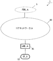
- FIG. 1 is a diagram for explaining an outline of a mobile communication system in the present embodiment.
- the mobile communication system 1 includes mobile terminal apparatuses UE_A10, eNB_A45, a core network_A90, and PDN_A5.
- UE_A10 may be a terminal device that can be wirelessly connected, and may be UE (User equipment), ME (Mobile equipment), or MS (Mobile equipment).
- UE User equipment
- ME Mobile equipment
- MS Mobile equipment
- the UE_A10 may be a CIoT terminal.
- the CIoT terminal is an IoT terminal that can be connected to the core network A90, and the IoT terminal includes a mobile phone terminal such as a smartphone, and may be various IT devices such as a personal computer and a sensor device.
- UE_A10 may request a connection optimized for CIoT terminals based on UE_A10 policies or network requests, or may request a conventional connection .
- UE_A10 may be set as a terminal device that connects to core network_A90 only by a communication procedure optimized for CIoT terminals in advance at the time of shipment.
- core network_A90 is an IP mobile communication network operated by a mobile operator.
- the core network_A90 may be a core network for a mobile communication operator that operates and manages the mobile communication system 1, or a core for a virtual mobile communication operator such as MVNO (Mobile Virtual Network Operator). It can be a network.
- the core network_A90 may be a core network for accommodating CIoT terminals.
- ENB_A45 is a base station constituting a radio access network used for UE_A10 to connect to core network_A90. That is, UE_A10 connects to core network_A90 using eNB_A45.
- core network_A90 is connected to PDN_A5.
- PDN_A5 is a packet data service network that provides a communication service to UE_A10, and may be configured for each service.
- a communication terminal is connected to the PDN, and UE_A10 can transmit and receive user data to and from the communication terminal arranged in PDN_A5.
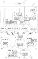
- Fig. 2 shows the first example of the configuration of the core network_90.
- the core network_A90 in Figure 2 (a) is HSS (Home Subscriber Server) _A50, AAA (Authentication, Authorization, Accounting) _A55, PCRF (Policy (enhanced Packet Data Gateway) _A65, SGW (Serving ⁇ Gateway) _A35, MME (Mobility Management Entity) _A40, SGSN (Serving GPRS Support Node) _A42.
- HSS Home Subscriber Server
- AAA Authentication, Authorization, Accounting
- PCRF Policy (enhanced Packet Data Gateway) _A65
- SGW Serving ⁇ Gateway
- MME Mobility Management Entity
- SGSN Serving GPRS Support Node
- the core network_A90 can be connected to a plurality of radio access networks (LTE AN_A80, WLAN ⁇ ANb75, WLAN ANa70, UTRAN_A20, GERAN_A25).
- LTE AN_A80, WLAN ⁇ ANb75, WLAN ANa70, UTRAN_A20, GERAN_A25 radio access networks
- the radio access network may be configured to be connected to a plurality of different access networks, or may be configured to be connected to any one access network. Furthermore, UE_A 10 can wirelessly connect to the radio access network.
- the access networks that can be connected by the WLAN access system are WLAN access network b (WLAN ANb75) connected to the core network via ePDG_A65, and WLAN access network a (WLAN ANa75) connected to PGW_A, PCRF_A60, and AAA_A55. Is configurable.
- each device is configured in the same manner as a conventional device in a mobile communication system using EPS, detailed description is omitted. Hereinafter, each device will be briefly described.
- PGW_A30 is connected to PDN_A5, SGW_A35, ePDG_A65, WLAN ANa70, PCRF_A60 and AAA_A55, and is a relay device that transfers user data as a gateway device for PDN_A5 and core network_A90.
- SGW_A35 is connected to PGW30, MME_A40, LTE AN80, SGSN_A42 and UTRAN_A20, and relay device that transfers user data as a gateway device between core network_A90 and 3GPP access network (UTRAN_A20, GERAN_A25, LTE AN_A80) It is.
- MME_A40 is connected to SGW_A35, LTE AN80, and HSS_A50, and is an access control device that performs location information management and access control of UE_A10 via LTE AN80.
- the core network_A90 may be configured to include a plurality of location management devices. For example, a location management device different from MME_A40 may be configured. A location management device different from MME_A40 may be connected to SGW_A35, LTE AN80, and HSS_A50 in the same manner as MME_A40.
- the MMEs may be connected to each other. Thereby, transmission / reception of the context of UE_A10 may be performed between MMEs.
- HSS_A50 is connected to MME_A40 and AAA_A55, and is a management node that manages subscriber information.
- the subscriber information of HSS_A50 is referred to at the time of access control of MME_A40, for example. Further, the HSS_A50 may be connected to a location management device different from the MME_A40.
- AAA_A55 is connected to PGW30, HSS_A50, PCRF_A60, and WLAN ANa70, and performs access control for UE_A10 connected via WLAN ANa70.
- PCRF_A60 is connected to PGW_A30, WLAN ANA75, AAA_A55, and PDN_A5, and performs QoS management for data delivery. For example, the QoS of the communication path between UE_A10 and PDN_A5 is managed.
- EPDG_A65 is connected to PGW30 and WLANWANb75, and delivers user data as a gateway device between core network_A90 and WLAN ANb75.
- SGSN_A42 is connected to UTRAN_A20, GERAN_A25 and SGW_A35 and is a control device for location management between 3G / 2G access network (UTRAN / GERAN) and LTE access network (E-UTRAN). Furthermore, SGSN_A42 has a PGW and SGW selection function, a UE time zone management function, and an MME selection function at the time of handover to E-UTRAN.
- each radio access network includes devices (for example, base station devices and access point devices) to which UE_A 10 is actually connected.
- devices for example, base station devices and access point devices
- a device used for connection a device adapted to a radio access network can be considered.
- LTE-AN80 is configured to include eNB_A45.
- eNB_A45 is a radio base station to which UE_A10 is connected in the LTE access system
- LTE-AN_A80 may be configured to include one or a plurality of radio base stations.
- WLAN AAN70 is configured to include WLAN APa72 and TWAG_A74.
- WLAN APa72 is a wireless base station to which UE_A10 connects with a WLAN access system that is reliable to the operator operating the core network_A90
- WLAN ANa70 is configured to include one or more wireless base stations It's okay.
- TWAG_A74 is a gateway device between the core network_A90 and the WLAN AAN70. Further, the WLAN APA 72 and the TWAG_A 74 may be configured by a single device.
- WLAN ANb75 includes WLAN ⁇ ⁇ APb76.
- WLAN APb76 is a wireless base station to which UE_A10 is connected in the WLAN access system when a trust relationship is not established with the operator operating the core network_A90, and WLAN ⁇ ⁇ ANb75 has one or more wireless base stations May be included.
- WLAN ANb75 is connected to core network_A90 using ePDG_A65, which is a device included in core network_A90, as a gateway.
- ePDG_A65 has a security function to ensure safety.
- UTRAN_A20 includes RNC (Radio Network Controller) _A24 and eNB (UTRAN) _A22.
- eNB (UTRAN) _A22 is a radio base station to which UE_A 10 is connected by UTRA (UMTS Terrestrial Radio Access), and UTRAN_A20 may be configured to include one or a plurality of radio base stations.
- the RNC_A24 is a control unit that connects the core network_A90 and the eNB (UTRAN) _A22, and the UTRAN_A20 may be configured to include one or a plurality of RNCs.
- the RNC_A24 may be connected to one or more eNB (UTRAN) _A22.
- the RNC_A24 may be connected to a radio base station (BSS (Base Station Subsystem) _A26) included in the GERAN_A25.
- BSS Base Station Subsystem
- GERAN_A25 includes BSS_A26.
- BSS_A26 is a radio base station to which UE_A10 is connected by GERA (GSM (registered trademark) / EDGE radio access), and GERAN_A25 may be configured by one or a plurality of radio base stations BSS. A plurality of BSSs may be connected to each other. BSS_A26 may be connected to RNC_A24.
- the core network_A90 may have the configuration shown in FIG.
- the core network_A90 in FIG. 3 (a) is composed of C-SGN (CIoT Serving Gateway Node) _A95 and HSS_A50.
- the core network_A90 includes AAA_A55 and / or PCRF_A60 and / or ePDG_A65 and / or SGSN_A42 in the core network_A90 in order to provide connectivity with access networks other than LTE. May be.
- C-SGN_A95 may be a node that plays the role of MME_A40, SGW_A35, and PGW_A30 in FIG.
- C-SGN_A95 may be a node for CIoT terminals.
- C-SGN_A95 may have a gateway device function between PDN_A and core network_A90, a gateway device function between core network_A90 and CIOTAN_A100, and a location management function of UE_A10.
- UE_A10 is connected to the core network_A90 via the radio access network CIOT AN_A100.
- Fig. 3 (b) shows the configuration of CIOT AN_A100.
- CIOT AN_A100 may be configured to include eNB_A45.
- ENB_A45 included in CIOT AN_A100 may be the same base station as eNB_A45 included in LTE AN_A80.
- eNB_A45 included in CIOT AN_A100 may be a base station for CIoT different from eNB_A45 included in LTE AN_A80.
- first core network and / or the second core network may be configured by a system optimized for IoT.
- UE_A10 being connected to each radio access network means being connected to a base station device, an access point, etc. included in each radio access network. Also via a base station device or access point.
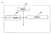
- FIG. 4 (a) shows the device configuration of eNB_A45.
- the eNB_A45 includes a network connection unit_A420, a control unit_A400, and a storage unit_A440.
- the network connection unit _A420 and the storage unit _A440 are connected to the control unit _A400 via a bus.
- Control unit_A400 is a functional unit for controlling eNB_A45.
- the control unit_A400 implements various processes by reading and executing various programs stored in the storage unit_A440.
- the network connection unit_A420 is a functional unit for the eNB_A45 to connect to the MME_A40 and / or SGW_A35 or C-SGN_A95. Furthermore, the network connection unit_A420 is a transmission / reception function unit in which the eNB_A45 transmits / receives user data and / or control data from the MME_A40 and / or SGW_A35 or C-SGN_A95.
- Storage unit_A440 is a functional unit that stores programs and data necessary for each operation of eNB_A45.
- the storage unit 640 includes, for example, a semiconductor memory, an HDD (Hard Disk Drive), or the like.
- the storage unit _A440 stores at least identification information and / or control information and / or flags and / or parameters included in control messages transmitted and received in the attach procedure and data transmission procedure described in 1.3 and 1.4. Good.
- eNB_A45 is provided with the transmission / reception part which transmits / receives UE_A10 and control information and / or user data. Further, an external antenna is connected to the transmission / reception unit.
- FIG. 6 (a) shows the device configuration of MME_A40.
- the MME_A 40 includes a network connection unit_B620, a control unit_B600, and a storage unit_B640.
- the network connection unit_B620 and the storage unit_B640 are connected to the control unit_B600 via a bus.
- Control unit_B600 is a functional unit for controlling MME_A40.
- the control unit_B600 implements various processes by reading and executing various programs stored in the storage unit_B640.
- the network connection unit_B620 is a functional unit for the MME_A40 to connect with the HSS_A50 and / or SGW_A35. Furthermore, the network connection unit_B620 is a transmission / reception function unit that allows the MME_A40 to transmit and receive user data and / or control data from the HSS_A50 and / or SGW_A35.
- Storage unit_B640 is a functional unit that stores programs and data necessary for each operation of MME_A40.
- the storage unit_B640 is configured by, for example, a semiconductor memory, an HDD (Hard Disk Drive), or the like.
- the storage unit _B640 stores at least identification information and / or control information and / or flags and / or parameters included in control messages transmitted and received in the attach procedure and data transmission procedure described in 1.3 and 1.4. Good.
- the storage unit_B640 stores an MME context 642, a security context 648, and MME emergency configuration data 650, as shown in the figure.
- the MME context includes an MM context and an EPS bearer context.
- the MME context may be composed of an EMM context and an ESM context.
- the MM context is an EMM context
- the EPS bearer context may be an ESM context.
- Fig. 7 (b), Fig. 8 (b) and Fig. 9 (b) show information elements of MME context stored for each UE.
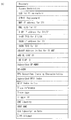
- the MME context stored for each UE is IMSI, IMSI-unauthenticated-indicator, MSISDN, MM State, GUTI, ME Identity, Tracking Area List, TAI of last TAU, ECGI (E-UTRAN Cell Global Identity), E-UTRAN Cell Identity Identity, CSG ID, CSG membership, Access mode, Authentication Vector, UE Radio Access Capability, MS Classmark 2, MS Classmark 3, Supported Codecs, UE Network Capability, MS Network Capability, UE Specific DRX Parameters , Selected NAS Algorithm, eKSI, K_ASME, NAS Keys and COUNT, Selected CN operator ID, Recovery, Access Restriction, ODB for PS parameters, APN-OI Replacement, MME IP address for S11, MME TEID for S11, S-GW for S11 / S4,
- IMSI is the user's permanent identification information. Same as IMSI stored in HSS_A50.
- IMSI-unauthenticated-indicator is instruction information indicating that this IMSI is not authenticated.
- MSISDN represents the phone number of the UE. MSISDN is indicated by the storage part of HSS_A50.
- MM State indicates the MME mobility management state.
- This management information includes the ECM-IDLE state in which the connection between the eNB and the core network is released, the ECM-CONNECTED state in which the connection between the eNB and the core network is not released, or the MME stores the location information of the UE. No EMM-DEREGISTERED state.
- GUTI Globally Unique Unique Temporary Identity
- MME identification information GUMMEI: GloballyGlobalUnique MME Identifier
- M-TMSI UE identification information
- the ID of ME IdentityUE for example, IMEI / IMISV.
- Tracking Area List is a list of tracking area identification information assigned to the UE.
- TAI of last TAU is tracking area identification information indicated in the latest tracking area update procedure.
- ECGI is the latest UE cell identification information known to MME_A40.
- E-UTRAN Cell Identity Age indicates the elapsed time since the MME acquired ECGI.
- the CSG ID is identification information of a CSG (Closed Subscriber Group) operated by a recent UE as known by the MME.
- CSG membership is the latest UE CSG member information known to MME.
- CSG membership indicates whether the UE is a CSG member.
- Access mode is an access mode of a cell identified by ECGI, and may be identification information indicating that ECGI is a hybrid that allows access to both CSG and non-CSG UEs.
- Authentication Vector indicates a temporary AKA (Authentication and Key Agreement) of a specific UE that the MME follows.
- the Authentication Vector is composed of a random value RAND used for authentication, an expected response XRES, a key K_ASME, and a language (token) AUTN authenticated by the network.
- Radio Access Capability is identification information indicating the radio access capability of the UE.
- MS Classmark 2 is a 3G / 2G (UTRAN / GERAN) CS domain core network classmark. MS Classmark 2 is used when the UE supports SRVCC (Single Radio Voice Call Continuit) for GERAN or UTRAN.
- SRVCC Single Radio Voice Call Continuit
- MS Classmark 3 is the class mark of the GERAN CS domain wireless network. MS Classmark 3 is used when the UE supports SRVCC (Single Radio Voice Call Continuit) for GERAN.
- SRVCC Single Radio Voice Call Continuit
- SupportedcsCodecs is a list of codes supported by CS domain. This list is used when the UE supports SRVCC for GERAN or UTRAN.
- UE Network Capability includes security algorithms and key derivation functions supported by the UE.
- MS Network Capability is information including at least one piece of information necessary for SGSN for UE having GERAN and / or UTRAN functions.
- UE Specific DRX Parameters are parameters used to determine the UE DRX (Discontinuous Reception) cycle length.
- DRX is a function for switching the UE to a low power consumption state when there is no communication for a certain period of time in order to reduce the power consumption of the battery of the UE as much as possible.
- “Selected NAS Algorithm” is a selected security algorithm of NAS (Non-Access Stream).
- EKSI is a set of keys indicating K_ASME. Whether or not to use a security key acquired by UTRAN or E-UTRAN security authentication may be indicated.
- K_ASME is an E-UTRAN key hierarchy key generated based on the encryption key CK (Cipher Key) and the complete key IK (Integrity Key).
- NAS Keys and COUNT consists of key K_NASint, key K_NASenc and NAS COUNT parameter.
- Key K_NASint is a key for encryption between UE and MME
- key K_NASenc is a key for security protection between UE and MME.
- NAS COUNT is a count that starts counting when a new key is set when security between the UE and the MME is established.
- the “selected CN” operator ID is identification information of the selected core network operator used for sharing the network among operators.
- Recovery is identification information indicating whether the HSS performs database restoration.
- Access Restriction is registration information for access restriction.
- ODB for PS parameters indicate the state of ODB (operator determined) barring.
- ODB is an access rule determined by a telecommunications carrier (operator).
- APN-OI Replacement is a domain name that replaces APN when constructing a PGW FQDN to perform DNS resolution. This alternate domain name applies to all APNs.
- MME IP address for S11 is the IP address of MME used for the interface with SGW.
- MME TEID for S11 is a TEID (Tunnel Endpoint Identifier) used in the interface with SGW.
- S-GW IP address for S11 / S4 is the IP address of SGW used at the interface between MME and SGW or between SGSN and MME.
- S GW TEID for S11 / S4 is the TEID of SGW used at the interface between MME and SGW or between SGSN and MME.
- SGSN IP address for S3 is the IP address of SGSN used for the interface between MME and SGSN.
- SGSN TEID for S3 is the SGSN TEID used in the interface between MME and SGSN.
- EnodeB Address in “Use” for “S1-MME” is the IP address of eNB that was recently used in the interface between MME and eNB.
- ENB UE S1AP ID is identification information of UE within eNB.
- MME UE S1AP ID is identification information of UE in MME.
- Subscribed UE-AMBR indicates the maximum value of MBR (Maximum Bit Rate) for uplink and downlink communication for sharing all Non-GBR (Guaranteed Bit Rate) bearers (non-guaranteed bearers) according to user registration information.
- MBR Maximum Bit Rate
- Non-GBR Guard Bit Rate
- UE-AMBR indicates the maximum value of MBR of uplink communication and downlink communication recently used to share all Non-GBR bearers (non-guaranteed bearers).
- EPS Subscribed ”Charging Characteristics indicates the charging characteristics of the UE.
- EPS Subscribed Charging Characteristics may indicate registration information such as normal, prepaid, fixed charge rate, or immediate billing.
- Subscribed RFSP Index is an index for a specific RRM configuration in E-UTRAN obtained from HSS.
- RFSP Index In Use is an index for a specific RRM configuration in E-UTRAN that has been used recently.
- Trace reference is identification information for identifying a specific trace record or a set of records.
- Trace type indicates the type of trace. For example, the type that HSS traces and / or the type that MME, SGW, or PGW traces may be indicated.
- Trigger ID is identification information that identifies the component that starts the trace.
- OMCM Identity is identification information that identifies the OMC that received the traced record.
- URRP-MME is identification information indicating that the UE activity notification from the MME is requested by the HSS.
- CSG Subscription Data is a related list of roaming destination PLMN (VPLMN) CSG ID and roaming destination equivalent PLMN.
- Each CSG ID may be associated with an expiration date indicating the expiration date of the CSG ID or an absent date indicating that there is no expiration date.
- the CSG ID may be used for a specific PDN connection via LIPA.
- Subscribed Periodic RAU / TAU Timer is a periodic RAU and / or TAU timer.
- MPS CS priority indicates that the UE is registered with eMLPP or 1x RTT priority service in the CS domain.
- MPS EPS priority is identification information indicating that it is registered in the MPS within the EPS domain.
- Voice Support Match Indicator indicates whether the UE's radio capabilities are compatible with the network configuration. For example, it indicates whether the SRVCC support by the UE matches the support for network voice calls.
- Homogenous Support of IMS Voice over PS Sessions for MME is instruction information indicating for each UE whether to support IMS voice calls over PS sessions.
- Homogenous Support of IMS Voice over PS Sessions for MME supports all IMS (IP Multimedia Subsystem) voice calls over PS (Packet Switched) sessions with all TAs (Tracking Area) managed by MME. ”And“ Not Supported ”indicating that there is no TA supporting IMS voice call on the PS session.
- IMS IP Multimedia Subsystem
- PS Packet Switched
- TAs Track Area
- the MME notifies the HSS of this instruction information. do not do.
- Fig. 10 (c) shows the information elements included in the MME context stored in the transmit / receive enabled state.
- the transmission / reception enabled state will be described later.
- the MME stored in the transmit / receive enabled state may be stored for each PDN connection.
- the MME context stored in the send / receive enabled state is APN Use, APN Restriction, APN Subscribed, PDN Type, IP Address, EPS PDN Charging Characteristics, APN-OI Replacement, SIPTO permissions, Local Home Network ID , LIPA permissions, WLAN offloadability, VPLMN Address Allowed, PDN GW Address Address Use (control information), PDN GW TEID for S5 / S8 (control information), MS Info Change Reporting Action, CSG Information Reporting Action, EPS Include subscribed QoS profile, Subscribed APN-AMBR, APN-AMBR, PDN GW GRE Key, forlink traffic (user data), Default bearer, and low access priority.
- APN in ⁇ Use indicates the recently used APN.
- This APN is composed of APN network identification information and default operator identification information.
- APN Restriction indicates the restriction of the combination of APN types for the APN associated with this bearer context. That is, it is information that limits the number of APNs that can be established and the type of APN.
- APINscribedSubscribed means registered APN received from HSS.
- PDN Type indicates the IP address type.
- the PDN type indicates IPv4, IPv6 or IPv4v6.
- IP Address indicates an IPv4 address or IPv6 Prefix.
- the IP address may store both IPv4 and IPv6 prefixes.
- EPS PDN Charging Characteristics indicates billing characteristics. EPS PDN Charging Characteristics may indicate, for example, normal, prepaid, fixed charge rate, or instant billing.
- APN-OI Replacement is a proxy domain name of APN that has the same role as APN-OI Replacement registered for each UE. However, the priority is higher than APN-OI Replacement for each UE.
- SIPTO permission indicates permission information for SIPTO (Selected IP Traffic Offload) of traffic using this APN. Specifically, SIPTO permissions prohibits the use of SIPTO, permits the use of SIPTO outside of the local network, permits the use of SIPTO in networks that include the local network, or allows only the local network to use SIPTO. Identify that you are allowed to use
- Local Home Network ID indicates identification information of the home network to which the base station belongs when SIPTO (SIPTO @ LN) using the local network is available.
- LIPA permissions is identification information indicating whether this PDN can be accessed via LIPA.
- the LIPA-permissions may be LIPA-prohibited that does not allow LIPA, or LIPA-only that allows LIPA only, or LIPA-conditional that permits LIPA by condition.
- WLAN offloadability is identification information indicating whether traffic connected by this APN can be offloaded to a wireless run using a link function between the wireless run and 3GPP, or whether a 3GPP connection is maintained.
- WLAN load ability may be divided for each RAT type. Specifically, different WLAN offload ability may exist between LTE (E-UTRA) and 3G (UTRA).
- VPLMN Address Allowed indicates that the UE is allowed to use only the HPLMN domain (IP address) PGW in the roaming PLMN (VPLMN), or the PGW in the VPLMN domain is connected using this APN. Indicates whether it will be added.
- IP address IP address
- PGW Address in Use indicates the latest IP address of the PGW. This address is used when transmitting a control signal.
- PDN GW TEID for S5 / S8 (control information) is a TEID used for transmission / reception of control information at the interface (S5 / S8) between SGW and PGW.
- MS Info Change Reporting Action is an information element indicating that it is necessary to notify the PGW that the user location information has been changed.
- CSG Information Reporting Action is an information element indicating that it is necessary to notify the PGW that the CSG information has been changed.
- Presence Reporting Area Action indicates that it is necessary to notify the change of whether or not the UE exists in the presence reporting area (Presence Reporting Area).
- This information element is divided into identification information of the presence report area and elements included in the presence report area.
- the EPS “subscribed” QoS profile shows the QoS parameters at the bearer level for the default bearer.
- Subscribed APN-AMBR is the maximum value of MBR (Maximum Bit Rate) for uplink and downlink communication for sharing all Non-GBR bearers (non-guaranteed bearers) established for this APN according to user registration information Indicates.
- MBR Maximum Bit Rate
- APN-AMBR is the maximum value of MBR (Maximum Bit ⁇ ⁇ Rate) for uplink and downlink communication to share all Non-GBR bearers (non-guaranteed bearers) established for this APN determined by PGW Indicates.
- PDN-GW-GRE-Key-for-link-traffic (user data) is a GRE (Generic Routing Encapsulation) key for uplink communication of user data at the interface between SGW and PGW.
- GRE Generic Routing Encapsulation
- Default bearer is EPS bearer identification information for identifying the default bearer in the PDN connection.
- Low access priority indicates that the UE requested a low access priority (low access priority) when the PDN connection is open.
- Fig. 11 (d) shows the MME context stored for each bearer.
- the MME context stored for each bearer is EPS Bearer ID, TI, S-GW IP address for S1-u, S-GW TEID for S1u, PDN GW TEID for S5 / S8, PDN GW IP Include address for S5 / S8, EPS bearer QoS, TFT.
- EPS Bearer ID is the only identification information that identifies EPS bearer for UE connection via E-UTRAN.
- TI is an abbreviation for Transaction Identifier, and is identification information that identifies a bidirectional message flow (Transaction).
- S-GW IP address for S1-u is the IP address of SGW used at the interface between eNB and SGW.
- S-GW TEID for S1u is the SGW TEID used at the interface between eNB and SGW.
- PDN GW TEID for S5 / S8 is PGW TEID for user data transmission of the interface between SGW and PGW.
- PDN “GW IP address” for “S5 / S8” is the IP address of PGW for user data transmission of the interface between SGW and PGW.
- EPS bearer QoS consists of QCI (QoS Class Identifier) and ARP (Allocation and Retention Priority).
- QCI indicates the class to which QoS belongs.
- QoS can be divided into classes according to the presence / absence of bandwidth control, allowable delay time, and packet loss rate.
- QCI includes information indicating priority.
- ARP is information indicating the priority related to maintaining a bearer.
- TFT Traffic Flow Template
- the information elements included in the MME context shown in FIGS. 7 to 11 are included in either the MM context 644 or the EPS bearer context 646.
- the MME context for each bearer shown in FIG. 11 (d) may be stored in the EPS bearer context, and other information elements may be stored in the MM context.
- the MME context stored in the transmit / receive enabled state shown in FIG. 10 (c) and the MME context for each bearer shown in FIG. 11 (d) may be stored in the EPS bearer context, and other information elements may be stored in the MM context. Good.
- the MME storage unit_B640 may store a security context 648.
- FIG. 12 (e) shows information elements included in the security context 648.
- FIG. 12 (e) shows information elements included in the security context 648.
- the security context consists of EPS AS security context and EPS NAS security context.
- the EPS AS security context is a context related to the security of the access layer (AS: Access Stream)
- the EPS NAS security context is a context related to the security of the non-access layer (NAS: Non-Access Stream).
- Fig. 12 (f) shows the information elements included in the EPS AS security context.
- the EPS AS security context includes a cryptographic key, Next Hop parameter (NH), Next Hop Chaining Counter parameter (NCC), and identifiers of the selected AS level cryptographic algorithms.
- Cryptographic key is an encryption key in the access layer.
- NH is an information element determined from K_ASME. It is an information element for realizing forward security.
- NCC is an information element associated with NH. This represents the number of vertical handovers that switch networks.
- Figure 12 (g) shows the information elements included in the EPS NAS security context.
- the EPS-NAS-security context may include K_ASME, UE-security-capabilitie, and NAS-COUNT.
- K_ASME is an E-UTRAN key hierarchy key generated based on keys CK and IK.
- UE Security Capabilitie is a set of identification information corresponding to the ciphers and algorithms used in the UE. This information includes information for the access layer and information for the non-access layer. Furthermore, if the UE supports access to UTRAN / GERAN, this information includes information for UTRAN / GERAN.
- NAS COUN is a counter that indicates the time during which K_ASME is operating.
- the security context 648 may be included in the MME context 642. Further, as shown in FIG. 6 (a), the security context 648 and the MME context 642 may exist separately.
- FIG. 12 (h) shows information elements stored in the MME emergency configuration data 650.
- the MME emergency configuration data is information used instead of the UE registration information acquired from the HSS.
- the MME emergency configuration data 650 includes em APN (Emergency Access Point Name), Emergency QoS profile, Emergency APN-AMBR, Emergency PDN GW identity, Non-3GPP HO Emergency PDN GW identity.
- [Em APN indicates the name of the access point used for emergency PDN connection.
- Emergency QoS profile indicates the QoS of the default bearer of em N APN at the bearer level.
- Emergency APN-AMBR indicates the maximum value of MBR for uplink and downlink for sharing Non-GBR bearer (non-guaranteed bearer) established for em APN. This value is determined by PGW.
- Emergency PDN GW identity is PGW identification information statically set for em APN. This identification information may be an FQDN or an IP address.
- Non-3GPP HO Emergency PDN GW identity is PGW identification information that is statically set for em APN when the PLMN supports handover to an access network other than 3GPP.
- This identification information may be an FQDN or an IP address.
- the MME_A 40 may manage the connection state for the UE while synchronizing with the UE.
- FIG. 13 (a) shows the device configuration of SGW_A35.
- the SGW_A35 includes a network connection unit_C1320, a control unit_C1300, and a storage unit_C1340.
- the network connection unit _C1320 and the storage unit _C1340 are connected to the control unit _C1300 via a bus.
- Control unit_C1300 is a functional unit for controlling SGW_A35.
- the control unit_C1300 implements various processes by reading and executing various programs stored in the storage unit_C1340.
- the network connection unit_C1320 is a functional unit for the SGW_A35 to connect to the MME_A40 and / or PGW_A30 and / or SGSN_A42. Furthermore, the network connection unit_C1320 is a transmission / reception function unit in which the SGW_A35 transmits / receives user data and / or control data from the MME_A40 and / or PGW_A30 and / or SGSN_A42.
- Storage unit_C1340 is a functional unit that stores programs and data necessary for each operation of SGW_A35.
- the storage unit_C1340 includes, for example, a semiconductor memory, an HDD (Hard Disk Disk Drive), or the like.
- the storage unit _C1340 stores at least identification information and / or control information and / or flags and / or parameters included in control messages transmitted and received in the attach procedure and data transmission procedure described in 1.3 and 1.4. Good.
- Storage unit_C1340 stores EPS bearer context 1342 as shown in the figure.
- the EPS bearer context includes one stored for each UE, one stored for each PDN, and one stored for each bearer.
- Fig. 14 (b) shows the information elements of EPS bearer context stored for each UE.
- the EPS bearer context stored for each UE is IMSI, MSI-unauthenticated-indicator, ME Identity, MSISDN, Selected CN CN operator id, MME TEID for S11, MME IP address for S11, S-GW TEID for S11 / S4, S-GW IP address for S11 / S4, SGSN IP address for S4, SGSN TEID for S4, Trace reference, Trace type, Trigger ID, OMC identity, Last known Cell Id, Last known Cell Include Id age.
- IMSI is the user's permanent identification information. Equivalent to IMSI of HSS_A50.
- IMSI-unauthenticated-indicator is instruction information indicating that this IMSI is not authenticated.
- ME Identity is UE identification information, and may be, for example, IMEI / IMISV.
- MSISDN represents the basic phone number of the UE. MSISDN is indicated by the storage part of HSS_A50.
- Selected CN operator “id” is identification information of the selected core network operator used for sharing the network among operators.
- MME TEID for S11 is the MME TEID used in the interface between MME and SGW.
- MME IP address for S11 is the MME IP address used in the interface between MME and SGW.
- S-GW TEID for S11 / S4 is the TEID of SGW used in the interface between MME and SGW or the interface between SGSN and SGW.
- S-GW IP address for S11 / S4 is the IP address of SGW used in the interface between MME and SGW or the interface between SGSN and SGW.
- SGSN IP address for S4 is the IP address of SGSN used in the interface between SGSN and SGW.
- SGSN TEID for S4 is the SGSN TEID used in the interface between SGSN and SGW.
- Trace reference is identification information for identifying a specific trace record or a set of records.
- Race ⁇ ⁇ Type indicates the type of trace. For example, the type that HSS traces and / or the type that MME, SGW, or PGW traces may be indicated.
- Trigger ID is identification information that identifies the component that starts the trace.
- OMCM Identity is identification information that identifies the OMC that received the traced record.
- “Last known Cell ID” is the latest location information of the UE notified from the network.
- Last known Cell ID is information indicating the period from when the Last known Cell ID is stored.
- the EPS bearer context includes an EPS bearer context stored in a transmit / receive enabled state.
- the transmission / reception enabled state will be described later.
- the EPS bearer context stored in the transmission / reception enabled state may be stored for each PDN connection.
- FIG. 15 (c) shows an EPS bearer context stored in a transmit / receive enabled state.
- the EPS bearer context stored in the transmit / receive enabled state is APN Use, EPS PDN Charging Characteristics, P-GW Address in Use (control information), P-GW TEID for S5 / S8 (control information) , P-GW Address in Use (user data), P-GW GRE Key for uplink (user data), S-GW IP address for S5 / S8 (control information), S-GW TEID for S5 / S8 (control information) , S GW Address in Use (user data), S-GW GRE Key for downlink traffic (user data), Default Bearer are included.
- APN in ⁇ Use indicates the recently used APN.
- This APN is composed of APN network identification information and default operator identification information. This information is information acquired from the MME or SGSN.
- EPS PDN Charging Characteristics indicates billing characteristics. EPS PDN Charging Characteristics may indicate, for example, normal, prepaid, fixed charge rate, or instant billing.
- P-GW Address in Use is the IP address of the PGW that was used when the SGW recently sent control information.
- P-GW TEID for S5 / S8 (control information) is an interface between SGW and PGW, and is TEGW of PGW used for transmission of control information.
- P-GW In Use is the IP address of the PGW that SGW used recently when sending user data.
- P-GW GRE Key for uplink (user data) is a GRE key for user data uplink communication of the interface between SGW and PGW.
- S-GW IP address for S5 / S8 (control information) is the IP address of SGW used for the interface of control information between SGW and PGW.
- S-GW TEID for S5 / S8 (control information) is the TEID of SGW used for the interface of control information between GW and PGW.
- S GW Address Use is the IP address of the SGW that was recently used by the SGW to send user data.
- S-GW GRE Key downlink traffic (user data) is an uplink GRE key used for user data interface between SGW and PGW.
- Default Bearer is identification information for identifying the default bearer in the PDN connection when the PDN connection is established.
- EPS bearer context of SGW includes EPS bearer context for each bearer.
- FIG. 15 (d) shows an EPS bearer context for each bearer.
- EPS bearer context for each bearer is EPS Bearer Id, TFT, P-GW Address in Use (user data), P-GW TEID for S5 / S8 (user data), S-GW IP address for S5 / S8 (user data), S-GW TEID for S5 / S8 (user data), S-GW IP address for S1-u, S12 and S4 (user data), S-GW TEID for S1-u, S12 and S4 (user data), eNodeB IP address for S1-u, eNodeB TEID for S1-u, RNC IP address for S12, RNC TEID for S12, SGSN IP address for S4 (user data), SGSN TEID for S4 (user data) , EPS Bearer QoS, Charging Id.
- EPS Bearer Id is the only identification information that identifies EPS bearers for UE connections via E-UTRAN. That is, it is identification information for identifying a bearer.
- TFT indicates all packet filters associated with the EPS bearer.
- PP-GW In ⁇ ⁇ ⁇ Use is the interface between SGW and PGW, and is the IP address of the PGW that was recently used for user data transmission.
- P-GW TEID for S5 / S8 (user data) is the PGW TEID for user data interface between SGW and PGW.
- S-GW IP address for S5 / S8 (user data) is the IP address of SGW for user data received from PGW.
- S-GW TEID for S5 / S8 (user data) is SGW's TEID for user data interface between SGW and PGW.
- S-GW IP address for S1-u, S12 and S4 are SGW IP addresses used at the interface between SGW and 3GPP access network (LTE access network or GERAN / UTRAN).
- S-GW TEID for S1-u, S12 and ⁇ ⁇ ⁇ S4 (user data) are SGW TEIDs used at the interface between SGW and 3GPP access network (LTE access network or GERAN / UTRAN).
- ENodeB IP address for S1-u is the IP address of eNB used for transmission between SGW and eNB.
- ENodeB TEID for S1-u is the eNB TEID used for transmission between SGW and eNB.
- RNC IP address for S12 is the RNC IP address used for the interface between SGW and UTRAN.
- RNC TEID for S12 is the RNC TEID used for the interface between SGW and UTRAN.
- SGSN IP address for S4 (user data) is an IP address of SGSN used for transmission of user data between SGW and SGSN.
- SGSN TEID for S4 (user data) is the SGSN TEID used to transmit user data between SGW and SGSN.
- EPS Bearer QoS represents the QoS of this bearer and may include ARP, GBR, MBR, and QCI.
- ARP is information indicating the priority related to maintaining a bearer.
- GBR Guaranteed Bit Bit Rate
- MBR Maximum Bit Bit Rate
- QCI can be divided into classes according to the presence / absence of bandwidth control, allowable delay time, packet loss rate, and the like. QCI includes information indicating priority.
- Charging Id is identification information for recording the billing generated by SGW and PGW.
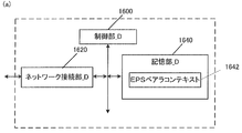
- FIG. 16 (a) shows the device configuration of PGW_A30.
- the PGW_A 30 includes a network connection unit_D1620, a control unit_D1600, and a storage unit_D1640.
- the network connection unit _D1620 and the storage unit _D1640 are connected to the control unit _D1600 via a bus.
- Control unit_D1600 is a functional unit for controlling PGW_A30.
- the control unit_D1600 implements various processes by reading and executing various programs stored in the storage unit_D1640.
- the network connection unit_D1620 is a functional unit for the PGW_A30 to connect to the SGW_A35 and / or PCRF_A60 and / or ePDG_A65 and / or AAA_A55 and / or GW_A74.
- the network connection unit_D1620 is a transmission / reception function unit in which the PGW_A30 transmits / receives user data and / or control data from / to the SGW_A35 and / or PCRF_A60 and / or ePDG_A65 and / or AAA_A55 and / or GW_A74.
- Storage unit_D1640 is a functional unit that stores programs and data necessary for each operation of PGW_A30.
- the storage unit_D1640 is configured by, for example, a semiconductor memory, an HDD (Hard Disk Disk Drive), or the like.
- the storage unit_D1640 may store at least identification information and / or control information and / or flags and / or parameters included in a control message transmitted and received in an attach procedure and a data transmission procedure described later.
- the storage unit_D1640 stores the EPS bearer context 1642 as shown in the figure.
- EPS bearer context what is stored for each UE, what is stored for each APN, what is stored in a transmit / receive enabled state, and what is stored for each bearer are separately stored. May be.
- FIG. 17 (b) shows information elements included in the EPS bearer context stored for each UE.
- EPS bearer context stored for each UE includes IMSI, IMSI-unauthenticated-indicator, ME Identity, MSISDN, Selected CN operator id, RAT type, Trace reference, Trace type, Trigger id, OMC identity. Including.
- IMSI is identification information assigned to a user who uses the UE.
- IMSI-unauthenticated-indicator is instruction information indicating that this IMSI is not authenticated.
- ME Identity is the UE ID, and may be, for example, IMEI / IMISV.
- MSISDN represents the basic phone number of the UE. MSISDN is indicated by the storage part of HSS_A50.
- the “selected CN” operator ID is identification information of the selected core network operator used for sharing the network among operators.
- RAT type indicates the UE's recent RAT (Radio Access Technology).
- the RAT type may be, for example, E-UTRA (LTE) or UTRA.
- Trace reference is identification information for identifying a specific trace record or a set of records.
- Trace type indicates the type of trace. For example, the type that HSS traces and / or the type that MME, SGW, or PGW traces may be indicated.
- Trigger ID is identification information that identifies the component that starts the trace.
- OMCM Identity is identification information that identifies the OMC that received the traced record.
- Fig. 17 (c) shows the EPS bearer context stored for each APN.
- the EPS bearer context stored for each APN of the PGW storage unit includes APN in use and APN-AMBR.
- APN in ⁇ Use indicates the recently used APN.
- This APN is composed of APN network identification information and default operator identification information. This information is obtained from SGW.
- APN-AMBR indicates the maximum value of MBR (Maximum Bit Rate) of uplink communication and downlink communication for sharing all Non-GBR bearers (non-guaranteed bearers) established for this APN.
- MBR Maximum Bit Rate
- Fig. 18 (d) shows the EPS bearer context stored in the transmit / receive enabled state.
- the transmission / reception enabled state will be described later.
- the EPS bearer context stored in the transmission / reception enabled state may be stored for each PDN connection.
- the EPS bearer context stored in the transmit / receive enabled state is IP Address, PDN type, S-GW Address In use (control information), S-GW TEID for S5 / S8 (control information), S- GW Address In use (user data), S-GW GRE Key for downlink traffic (user data), P-GW IP address for S5 / S8 (control information), P-GW TEID for S5 / S8 (control information), P -GW Address in ⁇ ⁇ ⁇ Use (user data), P-GW GRE Key for uplink traffic (user data), MS Info Change Reporting support indication, MS Info Change Reporting Action, CSG Information Reporting Action, Presence Reporting Area Action, BCM, Default Bearer Include EPS PDN Charging Characteristics.
- IP Address indicates the IP address to which the UE is assigned in the transmit / receive enabled state.
- the IP address may be IPv4 and / or IPv6 prefix.
- PDN type indicates the type of IP address.
- PDN type indicates, for example, IPv4, IPv6, or IPv4v6.
- S-GW Address in Use is the IP address of the SGW that is recently used to transmit control information.
- S-GW TEID for S5 / S8 (control information) is the TEID of SGW used for transmission / reception of control information between SGW and PGW.
- S-GW In Use is the IP address of the SGW that was recently used for sending user data on the interface between the SGW and the PGW.
- S-GW GRE Key for downlink traffic is an interface between SGW and PGW, and is a GRE key assigned for use in downlink communication of user data from PGW to SGW.
- P-GW IP address for S5 / S8 (control information) is the IP address of the PGW used for control information communication.
- P-GW TEID for S5 / S8 (control information) is PGW TEID for communication of control information using the interface between SGW and PGW.
- P-GW Address in Use is the IP address of the PGW that was recently used to transmit user data using the interface between the SGW and the PGW.
- GRE Key for “uplink traffic” (user data) is a GRE key assigned for user data uplink communication between SGW and PGW, that is, transmission of user data from SGW to PGW.
- MS Info Change Reporting Reporting support indication indicates that the MME and / or SGSN supports the process of notifying the user location information and / or the user CSG information.
- MS Info Change Reporting Action is information indicating whether the MME and / or SGSN is requested to transmit a change in the user location information.
- CSG Information Reporting Action is information indicating whether the MME and / or SGSN is requested to transmit a change of the user's CSG information.
- This information includes (a) for CSG cells, (b) for hybrid cells where the user is a CSG member, (c) for hybrid cells where the user is not a CSG member, and combinations thereof. Shown separately.
- Presence Reporting Area Action indicates that it is necessary to notify the change of whether or not the UE exists in the presence reporting area (Presence Reporting Area).
- This information element is divided into identification information of the presence report area and elements included in the presence report area.
- BCM Breast Control Mode
- Default Bearer is identification information for identifying the default bearer included in the PDN connection when the PDN connection is established.
- EPS PDN Charging Characteristics is a charging characteristic.
- the charging characteristics may indicate, for example, normal (normal), prepaid, fixed charging rate, and immediate charging.
- FIG. 18 (e) shows an EPS bearer context stored for each EPS bearer.
- EPS bearer contexts are EPS Bearer Id, TFT, S-GW Address in Use (user data), S-GW TEID for S5 / S8 (user data), P-GW IP address for S5 / S8 (User data), P-GW TEID for S5 / S8 (User data), EPS Bearer QoS, Charging Id are included.
- EPS Bearer Id is identification information that identifies access via UE's E-UTRAN.
- TFT Traffic Flow Template
- S-GW Address in Use is the IP address of the SGW that was recently used for user data transmission.
- S-GW TEID for S5 / S8 (user data) is the SGW TEID for user data communication using the interface between SGW and PGW.
- P-GW IP address for S5 / S8 (user data) is the IP address of the PGW for user data received from the PGW.
- P-GW TEID for S5 / S8 (user data) is PGW TEID for user data communication between SGW and PGW.
- EPS Bearer QoS indicates the bearer QoS and may include ARP, GBR, MBR and QCI.
- ARP is information indicating the priority related to maintaining a bearer.
- GBR Guaranteed Bit Bit Rate
- MBR Maximum Bit Bit Rate
- QCI can be divided into classes according to the presence / absence of bandwidth control, allowable delay time, packet loss rate, and the like. QCI includes information indicating priority.
- Charging Id is billing identification information for identifying a record related to billing generated by SGW and PGW.
- FIG. 19 (a) shows a device configuration of C-SGN_A95.
- C-SGN_A95 includes a network connection unit_E1920, a control unit_E1900, and a storage unit_E1940.
- the network connection unit_E1920 and the storage unit_E1940 are connected to the control unit_E1900 via a bus.
- Control unit_E1900 is a functional unit for controlling C-SGN_A95.
- the control unit_E1900 realizes various processes by reading and executing various programs stored in the storage unit_E1940.
- Network connection unit_E1920 is a functional unit for C-SGN_A95 to connect with eNB_A45 and / or HSS_A50 and / or PDN_A5. Further, the network connection unit_E1920 is a transmission / reception function unit in which the C-SGN_A95 transmits / receives user data and / or control data from the eNB_A45 and / or HSS_A50 and / or PDN_A5.
- Storage unit_E1940 is a functional unit that stores programs and data necessary for each operation of C-SGN_A95.
- the storage unit_E1940 is configured by, for example, a semiconductor memory, an HDD (Hard Disk Disk Drive), or the like.
- the storage unit _E 1940 stores at least identification information and / or control information and / or flags and / or parameters included in control messages transmitted and received in the attach procedure and data transmission procedure described in 1.3 and 1.4. Good.
- the storage unit_E1940 stores a context A1942, a context B1944, a context C1946, and a context D1948 as shown in the figure.
- Context A 1942 may be the MME context 642 shown in FIG.
- the context B1944 may be the security context 648 shown in FIG. 6 (a).
- the context C1946 may be the MME emergency configuration data 650 shown in FIG. 6 (a).
- context D1948 may be the EPS bearer context 1342 shown in FIG. 13 (a).
- context E1950 may be the EPS bearer context 1642 shown in FIG.
- the IMSI may be included in each of the context A 1942, the context D 1948, and the context E 1950, or may be stored in any context.
- FIG. 20 (a) shows the device configuration of UE_A10.
- UE_A 10 includes a transmission / reception unit 2020, a control unit 2000, and a storage unit 2040.
- the transmission / reception unit 2020 and the storage unit 2040 are connected to the control unit 2000 via a bus.
- Control unit 2000 is a functional unit for controlling UE_A10.
- the control unit 2000 implements various processes by reading and executing various programs stored in the storage unit 2040.
- the transmission / reception unit 2020 is a functional unit for UE_A10 to connect to the LTE base station and connect to the IP access network.
- An external antenna 2010 is connected to the transmission / reception unit 2020.
- the storage unit 2040 is a functional unit that stores programs and data necessary for each operation of the UE_A10.
- the storage unit 2040 is configured by, for example, a semiconductor memory, an HDD (Hard Disk Drive), or the like.
- the storage unit 2040 stores the UE context 2042 as shown in the figure. Hereinafter, the information elements stored in the storage unit 2040 will be described.
- FIG. 21 (b) shows information elements included in the UE context stored for each UE.
- the UE context stored for each UE is IMSI, EMMEMState, GUTI, ME Identity, Tracking Area List, last visited TAI, Selected NAS Algorithm, Selected AS Algorithm, eKSI, K_ASME, NAS Keys and COUNT , TIN, UE Specific DRX Parameters, Allowed CSG list, Operator CSG list.
- IMSI is the permanent identification information of the subscriber.
- EMMM State indicates the UE mobility management status.
- the EMM-REGISTERED registered state, registered state
- the EMM-DEREGISTERD unregistered state, deregistered state
- GUTI is an abbreviation for Globally Unique Unique Temporary Identity and is temporary identification information of UE.
- the GUTI includes MME identification information (GUMMEI: GloballyGlobalUnique MME Identifier) and UE identification information (M-TMSI) in the specific MME.
- GUMMEI GloballyGlobalUnique MME Identifier
- M-TMSI UE identification information
- ME Identity is the ID of ME, and may be, for example, IMEI / IMISV.
- Tracking Area List is a list of tracking area identification information assigned to the UE.
- “Last” visited ”TAI is tracking area identification information included in the Tracking” Area ”List, and is identification information of the latest tracking area visited by the UE.
- “Selected NAS” Algorithm is the selected security algorithm of the NAS.
- “Selected AS” Algorithm is a security algorithm selected by AS.
- EKSI is a set of keys indicating K_ASME. Whether or not to use a security key acquired by UTRAN or E-UTRAN security authentication may be indicated.
- K_ASME is an E-UTRAN key hierarchy key generated based on keys CK and IK.
- NAS Keys and COUNT is composed of key K_NASint, key K_NASenc and NAS COUNT.
- K_NASint is a key for encryption between UE and MME
- K_NASenc is a key for security protection between UE and MME.
- NAS COUNT is a count that starts counting when a new key is set when security between the UE and the MME is established.
- TIN Temporal Identity used in Next update
- RAU / TAU location information update procedure
- UE Specific DRX Parameters is the DRX (Discontinuous Reception) cycle length of the selected UE.
- the Allowed CSG list is a list of PLMNs associated with the CSG ID of the member to which the authorized UE belongs under the control of both the user and the operator.
- the Operator CSG list is a list of PLMNs associated with the CSG ID of the member to which the authorized UE belongs under the control of the operator only.
- FIG. 21 (c) shows the UE context stored in the transmit / receive enabled state.
- the transmission / reception enabled state will be described later.
- the UE context stored in the transmit / receive enabled state may be stored for each PDN connection.
- the UE context stored in the transmission / reception enabled state includes APN in Use, APN-AMBR, Assigned PDN Type, IP Address, Default Bearer, and WLAN offloadability.
- APNAPin Use is a recently used APN. This APN may be composed of network identification information and default operator identification information.
- APN-AMBR indicates the maximum value of MBR for uplink and downlink for sharing Non-GBR bearer (non-guaranteed bearer). APN-AMBR is established for each APN.
- Assigned PDN Type is the type of PDN assigned from the network. Assigned PDN Type may be, for example, IPv4, IPv6, or IPv4v6.
- the IP address is an IP address assigned to the UE, and may be an IPv4 address or an IPv6 prefix.
- Default Bearer is EPS bearer identification information that identifies the default bearer in a PDN connection when a PDN connection is established.
- WLAN offloadability is WLAN offload permission information indicating whether to permit offload to WLAN using the interworking function between WLAN and 3GPP or to maintain 3GPP access.
- FIG. 21 (d) shows a UE context for each bearer stored in the UE storage unit.
- the UE context for each bearer includes EPS Bearer ID, TI, EPS bearer QoS, and TFT.
- EPS Bearer ID is bearer identification information.
- TI is an abbreviation for Transaction Identifier, and is identification information that identifies a bidirectional message flow (Transaction).
- TFT Traffic Flow Template
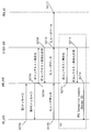
- the communication procedure in this embodiment includes an attach procedure (S2200), a transmission / reception means selection process (S2202), a first transmission / reception procedure (S2204), a second transmission / reception procedure (S2206), and a third transmission / reception procedure. (S2208).
- first transmission / reception procedure (S2204) and / or the second transmission / reception procedure (S2206) and / or the third transmission / reception procedure (S2208) can be omitted depending on conditions. Details of the conditions under which each procedure is executed and the processing will be described below.
- the connectionless communication in the present embodiment may be a communication in which UE_A 10 includes at least a process of including a NAS (Non Access Stratum) message including a data packet in an RRC (Radio R Source Control) message and transmitting it to eNB_A45. And or communication which transmits / receives a data packet between UE_A10 and eNB_A45, without establishing an RRC connection. And or communication which performs transmission / reception of a data packet in UE_A10 in an idle state may be sufficient.
- NAS Non Access Stratum
- RRC Radio R Source Control
- the active mode in the present embodiment means that UE_A10 and / or eNB_A45 and / or C-SGN_A95 establishes a DRB (Data Radio Bearer) and / or Default Bearer and / or PDN connection, and It may be a mode indicating a state where data can be transmitted and received.
- DRB Data Radio Bearer
- the DRB in the present embodiment may be a communication path such as a radio bearer established for transmission / reception of user data.
- the PDN connection in the present embodiment may be a connection for user data transmission / reception established between UE_A10 and C-SGN_A95.
- the idle mode in the present embodiment refers to UE_A10 and / or eNB_A45 and / or C-SGN_A95 releasing DRB and / or Default Bearer and / or PDN connection resources, and transmitting and receiving user data. It may be a mode indicating an incapable state.
- UE_A10, and / or eNB_A45, and / or C-SGN_A95 indicates that DRB, and / or Default Bearer, and / or PDN connection continue to be retained. It may be.
- the transmission / reception enabled state in the present embodiment is a state in which user data can be transmitted / received between UE_A 10 and PDN_A 5.
- the transmission / reception enabled state may be a state in which UE_A10 and / or PDN_A5, and / or eNB_A45, and / or C-SGN_A95 perform transmission / reception of user data.
- the transmission / reception enabled state may include a first mode, a second mode, a third mode, and a fourth mode.
- the first mode may be a mode in which UE_A10 and / or eNB_A45 and / or C-SGN_A95 transmits and receives user data without connection.
- the first mode may be a mode in which UE_A10 and / or eNB_A45 transmits and receives user data without establishing an RRC connection.
- the first mode may be a mode in which UE_A10 and / or C-SGN_A95 transmits and receives user data included in the NAS message.
- the first mode may be a mode in which UE_A10 and / or eNB_A45 transmits / receives user data included in the RRC message.
- the first mode may be a mode in which UE_A10 and / or eNB_A45 transmits and receives a NAS-PDU (Packet Data Unit) included in the RRC message.
- the NAS-PDU may be a control message including user data in a NAS message.
- the first mode may be a mode in which UE_A10 and / or eNB_A45 transmits / receives user data using SRB (Signalling Radio Bearer).
- SRB Synignalling Radio Bearer
- the first mode may be a mode in which UE_A10 and / or eNB_A45 transmits / receives user data using CRB (Control Signaling Radio Radio).
- CRB Control Signaling Radio Radio
- the SRB and CRB may be communication paths such as a radio bearer used for transmission / reception of control messages.
- the first mode may be a mode in which user data is transmitted and received using a bearer that UE_A10 and / or eNB_A45 and / or C-SGN_A95 transmits and receives control information.
- UE_A10 and / or eNB_A45 and / or C-SGN_A95 may transmit and receive user data using the first transmission / reception procedure.
- the second mode may be a mode in which UE_A10 and / or eNB_A45 and / or C-SGN_A95 establishes a connection and transmits / receives user data.
- the second mode may be a mode in which UE_A10 and / or eNB_A45 establishes an RRC connection and transmits / receives user data.
- the second mode may be a mode in which UE_A10 and / or eNB_A45 and / or C-SGN_A95 establishes a PDN connection and transmits / receives user data.
- the second mode may be a mode in which UE_A10 and / or eNB_A45 transmits and receives user data using DRB (Data Radio Bearer).
- DRB Data Radio Bearer
- the second mode may be a mode in which UE_A10 and / or eNB_A45 and / or C-SGN_A95 establishes a bearer for transmitting and receiving user data and transmits and receives user data.
- the second mode may be a mode in which UE_A10 and / or eNB_A45 and / or C-SGN_A95 establishes a default bearer and transmits / receives user data.
- the second mode may be a mode in which the context is maintained even when UE_A10 and / or eNB_A45 and / or C-SGN_A95 transitions to the idle mode.
- the second mode may be a mode in which UE_A10 and / or eNB_A45 can send and receive a NAS message in the third RRC message.
- UE_A10 and / or eNB_A45 and / or C-SGN_A95 may transmit and receive user data using the second transmission / reception procedure.
- the third mode may be a mode in which UE_A10, and / or eNB_A45, and / or C-SGN_A95 transmits and receives user data without connection, and is a mode in which a connection is established and user data is transmitted and received. Also good.
- the third mode may be a mode in which UE_A10 and / or eNB_A45 transmits / receives user data without establishing an RRC connection.
- the third mode may be a mode in which UE_A10 and / or C-SGN_A95 is included in the NAS message to transmit / receive user data.
- the third mode may be a mode in which UE_A10 and / or eNB_A45 transmits / receives user data included in the RRC message.
- the first mode may be a mode in which UE_A10 and / or eNB_A45 transmits and receives a NAS-PDU (Packet Data Unit) included in the RRC message.
- NAS-PDU Packet Data Unit
- the third mode may be a mode in which UE_A10 and / or eNB_A45 transmits / receives user data using SRB (Signalling Radio Bearer).
- SRB Synignalling Radio Bearer
- the third mode may be a mode in which UE_A10 and / or eNB_A45 transmits / receives user data using CRB (Control Signalling Radio Radio).
- CRB Control Signalling Radio Radio
- the third mode may be a mode in which user data is transmitted and received using a bearer that UE_A10 and / or eNB_A45 and / or C-SGN_A95 transmits and receives control information.
- the third mode may be a mode in which UE_A10 and / or eNB_A45 establishes an RRC connection and transmits / receives user data.
- the third mode may be a mode in which UE_A10 and / or eNB_A45 and / or C-SGN_A95 establishes a PDN connection and transmits / receives user data.
- the third mode may be a mode in which UE_A10 and / or eNB_A45 transmits / receives user data using DRB (Data Radio Bearer).
- DRB Data Radio Bearer
- the third mode may be a mode in which UE_A10 and / or eNB_A45 and / or C-SGN_A95 establishes a bearer for transmitting and receiving user data and transmits and receives user data.
- the third mode may be a mode in which UE_A10 and / or eNB_A45 and / or C-SGN_A95 establishes a default bearer and transmits / receives user data.
- the third mode may be a mode in which the context is kept even when UE_A10 and / or eNB_A45 and / or C-SGN_A95 transitions to the idle mode.
- the third mode may be a mode in which UE_A10 and / or eNB_A45 can transmit and receive a NAS message in the third message of RRC.
- UE_A10 and / or eNB_A45 and / or C-SGN_A95 may transmit / receive user data using the first transmission / reception procedure and / or the second transmission / reception procedure.
- the fourth mode may be a mode in which UE_A10 and / or eNB_A45 and / or C-SGN_A95 establishes a connection and transmits / receives user data.
- the fourth mode may be a mode in which UE_A10 and / or eNB_A45 establishes an RRC connection and transmits / receives user data.
- the fourth mode may be a mode in which UE_A10 and / or eNB_A45 and / or C-SGN_A95 establishes a PDN connection and transmits / receives user data.
- the fourth mode may be a mode in which UE_A10 and / or eNB_A45 transmits and receives user data using DRB.
- the fourth mode may be a mode in which UE_A10 and / or eNB_A45 and / or C-SGN_A95 establishes a bearer for transmitting and receiving user data and transmits and receives user data.
- the fourth mode may be a mode in which UE_A10 and / or eNB_A45 and / or C-SGN_A95 establishes a default bearer and transmits / receives user data.
- the fourth mode may be a mode in which UE_A10 and / or eNB_A45 and / or C-SGN_A95 establishes two or more bearers and transmits / receives user data.
- the fourth mode may be a mode in which the context is discarded when UE_A10 and / or eNB_A45 and / or C-SGN_A95 transitions to the idle mode.
- the fourth mode may be a mode in which UE_A10 and / or eNB_A45 cannot transmit / receive by putting a NAS message in the third message of RRC.
- UE_A10 and / or eNB_A45 and / or C-SGN_A95 may transmit and receive user data using the third transmission / reception procedure.
- the first identification information in the present embodiment may be information indicating that the UE_A 10 that performs the attach procedure is a CIoT (Cellular Internet Of Things) terminal.
- CIoT Cellular Internet Of Things
- the first identification information may be information indicating an attachment type indicating attachment by the CIoT terminal.
- the information indicating the attach type may be an attach type.
- the attachment type indicating attachment by a CIoT terminal may be CIoT attachment.
- the attachment by the CIoT terminal may be an attachment in which eNB_A45 selects C-SGN_A95 optimized for CIoT and UE_A10 connects to the selected C-SGN_A95.
- the first identification information may be information indicating that the UE_A 10 requests to connect to a system optimized for CIoT and / or IoT.
- the first identification information may be information indicating that the UE_A 10 has the capability of the CIoT terminal.
- the information indicating that UE_A10 has the capability of a CIoT terminal may be UE Capability.
- And / or the first identification information may be information indicating that the terminal has a terminal capability of transmitting user data using a radio bearer for transmitting and receiving a control message.
- the first identification information may be information indicating that the UE_A 10 performs transmission / reception of user data by the first transmission / reception procedure.
- the first identification information may be information indicating that it is requested to transmit user data using a radio bearer for transmitting and receiving a control message. More specifically, it may be information indicating that the UE_A 10 requests permission for performing transmission / reception of user data by the first transmission / reception procedure.
- the first identification information may be information indicating that the UE_A 10 requests transmission / reception of user data by the first transmission / reception procedure.
- / or the first identification information may be information indicating that user data is transmitted and received by being included in the NAS message.
- / or 1st identification information may be information which shows requesting
- And / or the first identification information may be information indicating that user data is transmitted and received by being included in the RRC message.
- And / or the first identification information may be information indicating that it is requested to transmit / receive user data included in the RRC message.
- / or the first identification information may be information indicating that UE_A10 and / or eNB_A45 transmits and receives a NAS-PDU (Packet Data Unit) included in the RRC message.
- NAS-PDU Packet Data Unit
- / or the first identification information may be information indicating that UE_A10 and / or eNB_A45 is included in the RRC message and requests to transmit / receive a NAS-PDU (Packet-Data Unit).
- NAS-PDU Packet-Data Unit
- the NAS PDU may be a control message including user data in a NAS message.
- the second identification information in the present embodiment may be information indicating that attachment by information indicating an attachment type indicating attachment by a CIoT terminal is permitted.
- the second identification information is network function information (Network Capability Information) indicating that it has a network capability capable of transmitting and receiving user data using a radio bearer for transmitting and receiving control messages. Good. More specifically, it may be information indicating that the C-SGN_A95 and / or the core network_A90 has an ability to connect to the CIoT terminal. Note that the information indicating that the C-SGN_A95 and / or the core network_A90 has the ability to connect to the CIoT terminal may be NW Capability.
- And / or the second identification information may be information indicating that C-SGN_A95 performs transmission / reception of user data by the first transmission / reception procedure.
- the second identification information may be information indicating that transmission of user data is permitted using a radio bearer for transmitting and receiving a control message. More specifically, it may be information indicating that C-SGN_A 95 permits the transmission / reception of user data by the first transmission / reception procedure.
- And / or the second identification information may be information indicating that the system is connected to a system optimized for IoT.
- the third identification information in the present embodiment may be UE function information (UE Capability Information) indicating that it has network capability to establish a radio bearer for user data transmission / reception and perform user data transmission / reception. . More specifically, it may be UE function information indicating that UE_A 10 has a function for transmitting and receiving user data by the second transmission and reception procedure.
- UE Capability Information UE Capability Information
- And / or the third identification information may be information indicating that the UE_A 10 performs transmission / reception of user data by the second transmission / reception procedure.
- And / or the third identification information may be information indicating that a radio bearer for user data transmission / reception is established to request transmission / reception of user data. More specifically, it may be information indicating that the UE_A 10 requests permission to perform transmission / reception of user data by the second transmission / reception procedure.
- And / or the third identification information may be information indicating that the UE_A 10 requests to transmit / receive user data by the second transmission / reception procedure.
- the third identification information indicates that the terminal has the ability to perform the first state transition, and / or requests to perform the first state transition. It may be information.
- the first state transition may be a state transition that transitions between an active state and an idle state based on a resume ID (Resume) ID) described later.
- the fourth identification information in the present embodiment may be network function information (Network Capability Information) indicating that a network bearer capable of transmitting / receiving user data by establishing a radio bearer for user data transmission / reception is provided. . More specifically, it may be network function information indicating that C-SGN_A95 and / or core network_A90 has a function for transmitting / receiving user data by the second transmission / reception procedure.
- Network Capability Information Network Capability Information
- And / or the fourth identification information may be information indicating that C-SGN_A95 performs transmission / reception of user data by the second transmission / reception procedure.
- / or the fourth identification information may be information indicating that a radio bearer for user data transmission / reception is established and transmission / reception of user data is permitted. More specifically, it may be information indicating that C-SGN_A 95 permits the transmission / reception of user data by the second transmission / reception procedure.
- the fourth identification information is information indicating that the network capability is capable of performing the first state transition, and / or information indicating that the first state transition is permitted. It may be.
- the first state transition may be a state transition that transitions between an active state and an idle state based on a resume ID that will be described later.
- the fifth identification information in the present embodiment may be information indicating that the eNB_A45 has a function for transmitting / receiving user data by the second transmission / reception procedure.
- the information indicating that the eNB_A45 has a function for transmitting and receiving user data by the second transmission / reception procedure may be eNB ⁇ ⁇ Capability.
- And / or the fifth identification information may be information indicating that the eNB_A45 performs transmission / reception of user data by the second transmission / reception procedure.
- And / or the fifth identification information may be information indicating that the eNB_A45 permits the transmission / reception of user data by the second transmission / reception procedure.
- And / or the fifth identification information may be information indicating that the eNB_A45 requests that user data be transmitted / received by the second transmission / reception procedure.
- the sixth identification information in the present embodiment may be information indicating the type of PDN address (PDN Address) requested by UE_A 10 for allocation.
- the information indicating the type of PDN address may be a PDN type (PDN Type).
- the PDN type may be information indicating IPv4, may be information indicating IPv6, or may be information indicating IPv4v6.
- / or the sixth identification information may be information indicating that it is required to establish DRB (Data Radio Bearer) and / or Default Bearer in the attach procedure.
- DRB Data Radio Bearer
- the seventh identification information in the present embodiment may be information indicating a PDN address assigned to UE_A10 by C-SGN_A95.
- the PDN address may be an IPv4 address (IPv4 Address), may be an interface ID (Interface Identifier) indicating information of the lower 64 bits of an IPv6 address (IPv6 Address), and both an IPv4 address and an IPv6 interface ID are used. It may be included.
- the PDN address may be composed of an IPv4 address field including an IPv4 address and / or an IPv6 address field including an IPv6 interface ID.
- the seventh identification information is the IP address of UE_A10. May be used as information indicating that it is permitted to establish DRB (Data Radio Bearer) and / or Default Bearer in the attach procedure.
- DRB Data Radio Bearer
- the seventh identification information may be used as information indicating that the UE_A 10 does not establish DRB (Data ⁇ Radio Bearer) and / or Default Bearer in the attach procedure in order to acquire the IP address.
- the seventh identification information may be used as information indicating that it is not necessary to acquire an IP address after the attach procedure is completed.
- the seventh identification information instructs UE_A10 to acquire an IPv4 address by DHCP after the attach procedure is completed or It may be used as requested information.
- the seventh identification information is generated and acquired by the stateless address setting procedure after the attach procedure is completed for UE_A10. Therefore, it may be used as information for instructing or requesting acquisition of an IPv6 prefix indicating information of upper 64 bits of an IPv6 address.
- the eighth identification information in this embodiment is information indicating that C-SGN_A95 and / or core network_A90 does not have a function for transmitting and receiving user data by the second transmission and reception procedure. Also good. Note that the information indicating that the C-SGN_A95 and / or the core network_A90 does not have a function for transmitting / receiving user data by the second transmission / reception procedure may be NW Capability.
- And / or the eighth identification information may be information indicating that C-SGN_A95 does not transmit / receive user data by the second transmission / reception procedure.
- And / or the eighth identification information may be information indicating that C-SGN_A95 does not permit transmission / reception of user data by the second transmission / reception procedure.
- the ninth identification information in the present embodiment may be information indicating the reason why C-SGN_A95 has decided not to transmit / receive user data by the second transmission / reception procedure.
- And / or the eighth identification information may be information indicating the reason why C-SGN_A95 has decided not to permit transmission / reception of user data by the second transmission / reception procedure.
- the tenth identification information in the present embodiment may be information indicating that UE_A10 performing the detach procedure is a CIoT terminal.
- the tenth identification information may be information indicating a detachment type indicating detachment by the CIoT terminal.
- the information indicating the detachment type may be a detachment type.
- the detach type indicating detachment by the CIoT terminal may be CIoT detach.
- And / or the eleventh identification information may be a detach type that requires disconnecting the connection to a system optimized for IoT (.
- / or the detachment by the CIoT terminal may be a detachment for the purpose of disconnecting the UE_A10 connected for the CIoT terminal.
- / or the tenth identification information may be information indicating that the UE_A10 disconnects the connection for transmitting / receiving user data using the first transmission / reception procedure and / or the second transmission / reception procedure.
- / or the tenth identification information is information indicating that the UE_A 10 requests to disconnect the connection for transmitting / receiving user data using the first transmission / reception procedure and / or the second transmission / reception procedure. May be.
- And / or the tenth identification information may be information indicating that the UE_A 10 requests to disconnect the connection to the system optimized for CIoT and / or IoT.
- the transmit / receive enabled state of the UE_A 10 that performs the detach procedure is the first mode, and / or the second mode, and / or the third mode.
- the eleventh identification information in the present embodiment may be information indicating that C-SGN_A95 performing the detach procedure is connected to the CIoT terminal.
- the eleventh identification information may be information indicating a detachment type indicating detachment by the CIoT terminal.
- the information indicating the detachment type may be a detachment type.
- the detach type indicating detachment by the CIoT terminal may be CIoT detach.
- the detachment by the CIoT terminal may be a detachment intended to disconnect the UE_A10 that is the CIoT terminal.
- And / or the eleventh identification information may be a detach type that requires disconnecting the connection to a system optimized for IoT (.
- / or the eleventh identification information is information indicating that C-SGN_A95 disconnects the connection for transmitting / receiving user data using the first transmission / reception procedure and / or the second transmission / reception procedure. Also good.
- / or the eleventh identification information is information indicating that C-SGN_A95 requests to disconnect the connection for transmitting / receiving user data using the first transmission / reception procedure and / or the second transmission / reception procedure. It may be.
- the twelfth identification information in the present embodiment may be information indicating the reason why C-SGN_A95 has decided to perform the detach procedure.
- the reason for deciding to detach is that UE_A10, C-SGN_A95, and / or eNB_A45 is in the first mode and / or the second mode, based on changes in subscriber information, operator policy, etc. And / or information indicating that the transmission / reception enabled state in the third mode is prohibited.
- UE_A10, C-SGN_A95, and / or eNB_A45 may transmit / receive user data in the first transmission / reception procedure and / or the second transmission / reception procedure based on changes in subscriber information, operator policy, etc. It may be information indicating that it is prohibited.
- And / or the twelfth identification information may be information indicating a reason why transmission / reception of user data by the first transmission / reception procedure and / or the second transmission / reception procedure is prohibited.
- the reason why the C-SGN_A95 has decided to perform the detach procedure, the reason that the transmission / reception of user data by the first transmission / reception procedure and / or the second transmission / reception procedure is prohibited may be included in the EMM cause.
- each identification information when two or more pieces of identification information among the first to twelfth identification information are included in the same control message and transmitted, each identification information may be included and transmitted. However, it may be included in the control message as one piece of identification information having the meaning indicated by each piece of identification information.
- the identification information may be an information element configured as a flag or a parameter.
- the attach procedure is a procedure initiated by UE_A10.
- UE_A 10 is a procedure for connecting to the network.
- the normal attach procedure is a procedure for connecting to the access network including the eNB 45, and further a procedure for connecting to the core network via the access network.
- UE_A10 establishes a communication path for transmitting / receiving user data to / from PDN_A5 by a normal attach procedure.
- the trigger for the UE_A 10 to start the attach procedure may be when the terminal power is turned on. Regardless of this, UE_A10 may start at any timing as long as UE_A10 is not connected to core network_A90. Further, UE_A10 may transition to a transmission / reception enabled state based on connection to the core network_A90 network and / or completion of the attach procedure.
- UE_A10 is a procedure that cannot connect to the network when the attach procedure is completed.
- the abnormal attach procedure is a procedure in which the UE_A10 connection attempt to the network ends in failure, and the UE_A10 and / or C-SGN_A95 rejects the UE_A10 from connecting to the network. Details of an example of an abnormal attach procedure will be described as a second attach procedure example and a third attach procedure example.
- UE_A10 transmits an attach request message to C-SGN_A95 (S2300).
- UE_A10 may transmit an attach request message to eNB_A45, and the transmitted attach request message may be transferred to C-SGN_A95 via eNB_A45.
- UE_A10 may transmit a PDN connection request message together with an attach request message.
- the attach request message is described as a combination of the attach request message and the PDN connection request message.
- the description of the present embodiment expresses that the identification information is included in the attach request message, it means that the identification information is included in the attach request message and / or the PDN connection request message.
- UE_A10 may include at least the first identification information and / or the third identification information and / or the sixth identification information in the attach request message.
- the UE_A 10 may request a transition to a transmission / reception enabled state by transmitting an attach request message including the first identification information and / or the third identification information.
- the eNB_A45 may include the fifth identification information in the attach request message and / or the message for transferring the attach request message.
- the eNB_A45 may request the transition to the transmission / reception enabled state by transmitting the fifth identification information in the attach request message and / or the message for transferring the attach request message.
- the first identification information and / or the third identification information and / or the sixth identification information is not included in the attach request message and transmitted to the C-SGN_A95, but is attached within the attach procedure. It may be transmitted in a control message different from the above.
- UE_A 10 may execute a request for ESM (EPS Session Management) information and a transmission / reception procedure of a control message that makes a response based on the request (S2302).
- ESM EPS Session Management
- C-SGN_A95 sends an ESM request message to UE_A10.
- UE_A10 receives the ESM request message and sends a response message to C-SGN_A95.
- the UE_A 10 may transmit the first identification information and / or the third identification information and / or the sixth identification information included in the response message.
- UE_A10 may encrypt and transmit the ESM response message. Further, UE_A10 may receive information for encrypting the ESM response message from C-SGN_A95. C-SGN_A95 may transmit information for encrypting the NAS message to UE_A10 upon reception of the attach request message.
- the NAS message that transmits information for encrypting the NAS message may be a Security Mode Command message.
- C-SGN_A95 receives the attach request message. Furthermore, the first identification information and / or the third identification information and / or the fifth identification information and / or the sixth identification information based on the reception of the attach request message or the reception of the ESM response message. To get.
- C-SGN_A95 may decide to make a transition to a transmit / receive enabled state for UE_A10 based on information included in the attach request message, subscriber information, and identification information held by C-SGN. Also, the first identification information, and / or the third identification information, and / or the fifth identification information, and / or the sixth identification information, and / or the subscriber information, and / or the second identification information. And / or based on the fourth identification information, the transmission / reception enabled state for transition may be determined.
- C -SGN_A95 approves and decides the transitionable transmission / reception enabled state. More specifically, the C-SGN_A95 includes the first identification information and / or the third identification information, and / or the fifth identification information, and / or the second identification information, and / or the fourth identification. Based on the information, it may be approved and determined whether the transitional transmittable / receiveable state is the first mode, the second mode, the third mode, or the fourth mode. .
- the above-described approval / determination process will be described as a first determination.
- C-SGN_A95 includes the first identification information, the third identification information, and the fifth identification information in the attach request, and C-SGN_A95 has the second identification information. If the terminal does not have the fourth identification information, the state may transit to the transmission / reception enabled state of the first mode.
- C-SGN_A95 includes the first identification information in the attach request, and the attachment request does not include the third identification information and / or the fifth identification information, and C-SGN_A95 includes the second identification information. If it has identification information, it may transition to the transmission / reception enabled state of the first mode.
- C-SGN_A95 includes the first identification information, the third identification information, and the fifth identification information in the attach request, and C-SGN_A95 does not have the second identification information.
- the state may transit to the transmission / reception enabled state of the second mode.
- C-SGN_A95 includes the first identification information, the third identification information, and the fifth identification information in the attach request, and C-SGN_A95 includes the second identification information and the fourth identification information. If it has, it may transition to the transmission / reception enabled state of the third mode.
- C-SGN_A95 may transition to a transmission / reception enabled state in the fourth mode.
- C-SGN_A95 may transition to the transmission / reception enabled state of the fourth mode when C-SGN_A95 does not have the second identification information and the fourth identification information.
- C-SGN_A95 decides to transition to a transmission / reception enabled state other than the first mode, it starts an IP-CAN session update procedure (S2304). Since the IP-CAN session update procedure may be the same as the conventional procedure, detailed description thereof is omitted.
- C-SGN_A95 may assign an IP address to UE_A10 as before. More specifically, C-SGN_A95 may assign the IP address of UE_A10 and include it in the seventh identification information.
- C-SGN_A95 transmits an attach acceptance message to eNB_A45 upon completion of the IP-CAN session update procedure (S2306).
- C-SGN_A95 may send a default EPS bearer context activation request message together with an attach acceptance message.
- the attach acceptance message is described as a combination of the attach acceptance message and the default EPS bearer context activation request message.
- the identification information when it is expressed that the identification information is included in the attach acceptance message, it means that the identification information is included in the attach acceptance message and / or the default EPS bearer context activation request message.
- C-SGN_A95 may include at least the second identification information and / or the fourth identification information and / or the seventh identification information in the attach acceptance message.
- C-SGN_A95 may set the connection state for UE_A10 to the idle mode in accordance with the transmission of the attach acceptance message based on the first determination.
- C-SGN_A95 may set the connection state to UE_A10 to the idle mode based on the transition to the transmission / reception enabled state.
- C-SGN_A95 may set the connection state to UE_A10 to the idle mode based on the fact that the transitionable transmission / reception enabled state is the first mode.
- the connection state to UE_A10 may be set to the active mode.
- C-SGN_A95 when the transmission / reception enabled state to be shifted is the first mode, based on the sixth identification information and / or the seventh identification information, C-SGN_A95 is connected to UE_A10 and / or eNB_A45, A DRB and / or Default Bearer and / or PDN connection for address acquisition may be established. In that case, based on the acquisition of the IP address of UE_A10, C-SGN_A95 may use the DRB and / or Default Bearer and / or PDN connection established with UE_A10 and / or eNB_A45 for IP address acquisition. It may be deleted.
- ENB_A45 receives the attach acceptance message and transmits an RRC message including the attach acceptance message to UE_A10 (S2308).
- the RRC message may be an RRC connection reconfiguration request message.
- the UE_A10 receives the RRC message including the attach acceptance message. Furthermore, when the second identification information, and / or the fourth identification information, and / or the seventh identification information is included in the attach acceptance message, the UE_A 10 acquires each identification information.
- UE_A10 transmits the RRC message to eNB_A45 (S2310).
- the RRC message may be an RRC connection reconfiguration completion message.
- ENB_A45 receives the RRC connection reconfiguration message and transmits a bearer configuration message to C-SGN_A95 based on the reception (S2312).
- UE_A10 transmits an RRC message including an attach completion message to eNB_A45 based on the reception of the attach acceptance message (S2314).
- UE_A10 may transmit a default EPS bearer context activation acceptance message together with an attach completion message.
- the attach completion message is described as a combination of the attach completion message and the default EPS bearer context activation acceptance message.
- the identification information is included in the attach completion message in the description of the present embodiment, it means that the identification information is included in the attach completion message and / or the default EPS bearer context activation acceptance message.
- the RRC message to be transmitted including the attach completion message may be a Direct Transfer message.
- the default EPS bearer context activation request message requires that the DRB and / or Default Bearer be established. It may be determined whether the message is a message to be received.
- the attach identification includes the second identification information and does not include the fourth identification information
- the default EPS bearer context activation request message establishes DRB and / or Default Bearer. The message may not be intended.
- the default EPS bearer context activation acceptance message may be a message intended to establish DRB and / or DefaulterBearer.
- UE_A10 transits to a transmit / receive enabled state based on the reception of the attach acceptance message and / or the transmission of the attach completion message.
- the UE_A 10 may recognize and detect the transitioned transmission / reception enabled state based on the second identification information and / or the fourth identification information and / or the seventh identification information. More specifically, the UE_A 10 determines whether the transitioned transmission / reception enabled state is the first mode based on the second identification information and / or the fourth identification information and / or the seventh identification information. Whether the mode is the second mode, the third mode, or the fourth mode may be recognized and detected.
- the above-described recognition and determination process will be described as a second determination.
- the UE_A 10 may transition to the transmission / reception enabled state of the first mode.
- UE_A10 may transition to the transmission / reception enabled state of the second mode when the second identification information is not included in the attachment acceptance and the fourth identification information is included.
- UE_A10 may transition to the transmission / reception enabled state of the third mode when the second identification information is included in the attachment acceptance and the fourth identification information is included.
- UE_A10 may transition to the transmission / reception enabled state of the fourth mode when the second identification information is not included in the attachment acceptance and the fourth identification information is not included.
- UE_A10 may establish DRB and / or Default Bearer and / or PDN connection based on reception of attach accept message and / or transmission of attach complete message.
- UE_A10 and / or eNB_A45 and / or C-SGN_A95 may not establish DRB and / or Default Bearer and / or PDN connection.
- UE_A10 and / or eNB_A45, And / or C-SGN_A95 may establish DRB and / or Default Bearer and / or PDN connection.
- ENB_45 receives the RRC message including the attach completion message, and transmits the attach completion message to C-SGN_A95 (S2316).
- UE_A10 may transition to the idle mode with the transmission of the attach completion message based on the second determination.
- the RRC message may be received from eNB_A45 as a response to the Direct Transfer message including the attach completion message, and UE_A10 may transition to the idle mode with the reception of the response message based on the second determination.
- the UE_A 10 may transmit the attach complete message and / or the direct transfer message including the identification information indicating the transition to the idle mode.
- eNB_A45 that has received the Direct Transfer message may transmit an RRC message as a response to UE_A10 based on the received identification information.
- the RRC message as a response may be a message for permitting transition to the idle mode.
- UE_A 10 can select whether to transition to the idle mode or maintain the active mode based on the second determination.
- UE_A10 when the transitionable transmission / reception enabled state is the first mode, based on the sixth identification information and / or the seventh identification information, UE_A10 is between eNB_A45 and / or C-SGN_A95, A connection for obtaining an IP address may be established.
- the connection may be DRB and / or Default ⁇ ⁇ Bearer and / or PDN connection.
- UE_A10 is eNB_A45 and / or C -A connection for obtaining an IP address may be established with SGN_A95.
- the established transmission / reception is the first mode
- the seventh identification information includes an IPv4 address indicated by all zeros such as 0.0.0.0 and / or some IPv6 interface ID.
- UE_A10 may establish a connection for acquiring an IP address.
- UE_A10 may lead the DHCP procedure to acquire an IPv4 address when the IPv4 address field of the seventh identification information includes an all-zero IPv4 address such as 0.0.0.0.
- UE_A10 may send a message requesting an IPv4 address to the DHCP server based on the above conditions. Then, UE_A10 may acquire the IPv4 address by receiving a response message including the IPv4 address assigned to UE_A10 from the DHCP server.
- UE_A10 obtains an IPv6 prefix indicating information of upper 64 bits of the IPv6 address by a stateless address setting procedure when any IPv6 interface ID is included in the IPv6 address field of the seventh identification information, An IPv6 address may be generated and acquired.
- UE_A10 may transmit an RS (Router Solicitation) message requesting an IPv6 prefix to the router and / or server based on the above conditions. Then, the UE_A 10 may acquire the IPv6 prefix by receiving an RA (Router Advertisement) including the allocated IPv6 prefix from the router and / or the server. Further, the UE_A 10 may generate and acquire IPv6 from the acquired IPv6 prefix and the IPv6 interface ID based on reception of the RA message and / or reception of the IPv6 prefix included in the RA message.
- RS Radio Solicitation
- RA Resource Advertisement
- the transitioned transmission / reception enabled state is the first mode
- the sixth identification information indicates IPv4
- the seventh identification information is not all zero as 0.0.0.0
- UE_A10 is When the IPv4 address to be used is included and the IPv6 interface ID is not included in the seventh identification information, the UE_A 10 does not need to establish a connection for acquiring the IP address.
- UE_A10 is established with eNB_A45 and / or C-SGN_A95 based on the acquisition of the IP address. Deleted connections may be deleted.
- the UE_A10 transmits a connection deletion request message to eNB_A45 and / or C-SGN_A95.
- the connection deletion request message may be a message for requesting deletion of a connection.
- ENB_A45 receives the connection deletion request message sent by UE_A10.
- eNB_A45 transmits a connection deletion request message to C-SGN_A95 based on the reception of the connection deletion request message.
- C-SGN_A95 receives the connection deletion request message transmitted by eNB_A45 and / or UE_A10.
- C-SGN_A95 transmits a connection deletion acceptance message to eNB_A45 and / or UE_A10 based on the reception of the connection deletion request message.
- the connection deletion acceptance message may be a response message of the connection deletion request message.
- C-SGN_A95 deletes the context of C-SGN_A95 for the connection based on the reception of the connection deletion request message and / or the transmission of the connection deletion acceptance message.
- the context of C-SGN_A95 for connection may be context D and / or context E shown in FIG.
- ENB_A45 receives the connection deletion acceptance message sent by C-SGN_A95.
- eNB_A45 transmits a connection deletion acceptance message to UE_A10 based on the reception of the connection deletion acceptance message.
- ENB_A45 deletes the context of eNB_A45 for the connection based on the reception of the connection deletion request message and / or the reception of the connection deletion acceptance message and / or the transmission of the connection deletion acceptance message.
- UE_A10 receives the connection deletion acceptance message transmitted by eNB_A45 and / or C-SGN_A95.
- UE_A10 deletes the context of UE_A10 for the connection based on the transmission of the connection deletion request message and / or the reception of the connection deletion acceptance message.
- the context of UE_A10 for connection may be a UE context stored in a transmit / receive enabled state illustrated in (c) of FIG. 21 and / or a UE context for each bearer illustrated in (d).
- UE_A10 and / or eNB_A45 and / or C-SGN_A95 delete the context for the connection, and the connection between UE_A10 and eNB_A45 and / or C-SGN_A95 is deleted.
- C-SGN_A95 receives the attach complete message.
- C-SGN_A95 may transition the connection state for UE_A10 to the idle mode based on the reception of the attach completion message.
- C-SGN_A95 may manage the state of UE_A10 as the idle mode based on the transmission of the attach acceptance message or the reception of the attach completion message.
- C-SGN_A95 transmits an attach acceptance message or attach complete when the transitioned transmit / receive enabled state is the second mode and / or the third mode and / or the fourth mode. Based on reception of the message, the state of UE_A10 may be managed as an idle mode.
- the UE_A 10 can acquire and store the UE context described in FIG. 21 from the core network_A 90 according to the attach procedure.
- C-SGN_A95 can acquire and store the contexts A to E described in FIG. 19 (a) from UE_A10, eNB_A45, or HSS_A50 by the attach procedure.
- UE_A10 connects to the network and completes the first attach procedure.
- UE_A10 and / or C-SGN_A95 transition to a transmission / reception enabled state.
- C-SGN_A95 receives the attach request message. Furthermore, the first identification information and / or the third identification information and / or the fifth identification information and / or the sixth identification information based on the reception of the attach request message or the reception of the ESM response message. To get.
- C-SGN_A95 may determine not to make a transition to a transmit / receive enabled state for UE_A10 based on information included in the attach request message and subscriber information. Further, based on the first identification information, and / or the third identification information, and / or the fifth identification information, and / or the sixth identification information, and / or the subscriber information, C-SGN_A95 is: You may determine not to change to a transmission / reception possible state.
- the above-described determination process will be described as the thirteenth determination.
- C-SGN_A95 transmits an attach rejection message to eNB_A45 based on the thirteenth determination (S2402).
- C-SGN_A95 may send a PDN connection rejection message together with an attach rejection message.
- the attach rejection message is described as a combination of the attach rejection message and the PDN connection rejection message.
- identification information is included in the attach rejection message, it means that the identification information is included in the attach rejection message and / or the PDN connection rejection message.
- C-SGN_A95 may include at least the second identification information and / or the eighth identification information in the attach rejection message.
- ENB_A45 receives the attach rejection message and transmits an RRC message including the attach rejection message to UE_A10 (S2208).
- the RRC message may be an RRC connection reconfiguration request message.
- UE_A10 receives the RRC message including the attach rejection message.
- UE_A10 may detect the failure to transition to the transmit / receive enabled state based on the reception of the attach rejection message and / or the second identification information and / or the eighth identification information included in the attach rejection message .
- UE_A10 may detect that the suspend process cannot be executed when each identification information included in the attach rejection message and / or the attach rejection message is received.
- the C-SGN_A95 or the MME_A40 may detect that the suspend process cannot be performed when the attach rejection message and / or the identification information included in the attach rejection message is transmitted.
- the suspend process refers to UE_A10, and / or C-SGN_A95, and / or MME_A40, when receiving a message for suspending the RRC connection from the base station apparatus, transitioning to the idle mode, And / or processing that keeps bearer context.
- UE_A10 fails to connect to the network and completes the second attach procedure.
- the UE_A10 may perform a new attach procedure based on the failure to connect to the network. More specifically, the UE_A 10 may perform a new attach procedure based on the second identification information and / or the eighth identification information included in the attach rejection message.
- the UE_A10 receives the RRC message including the attach acceptance message. Furthermore, when the second identification information, and / or the fourth identification information, and / or the seventh identification information is included in the attach acceptance message, the UE_A 10 acquires each identification information.
- UE_A10 may recognize and detect the transmission / reception enabled state permitted by C-SGN_A95 based on the second identification information and / or the fourth identification information and / or the seventh identification information.
- the transmission / reception enabled state permitted by C-SGN_A95 is based on the second identification information and / or the fourth identification information and / or the seventh identification information. It may be recognized and detected whether it is the second mode, the third mode, or the fourth mode.
- UE_A10 may decide to reject the transition to the transmission / reception enabled state based on authentication and detection of the transmission / reception enabled state permitted by C-SGN_A95. More specifically, when a transmission / reception enabled state different from the mode intended by UE_A10 is permitted by C-SGN_A95, UE_A10 may decide to reject the transition to the transmission / reception enabled state.
- the above-described recognition and determination process will be described as a fourteenth determination.
- UE_A10 determines to reject the transition to the transmit / receive enabled state by the fourteenth determination, UE_A10 transmits a default EPS bearer context activation rejection message to C-SGN_A95 via eNB_A45 (S2504).
- UE_A10 may include at least the ninth identification information in the default EPS bearer context activation rejection message. UE_A10 may reject the transition to the transmit / receive enabled state by transmitting an attach request message including the ninth identification information.
- C-SGN_A95 receives the default EPS bearer context activation rejection message.
- C-SGN_A95 detects that the transition to the transmit / receive enabled state has failed based on the received default EPS bearer context activation rejection message and / or the ninth identification information included in the default EPS bearer context activation rejection message. May be.
- C-SGN_A95 determines whether the received default EPS bearer context activation rejection message and / or the ninth identification information included in the default EPS bearer context activation rejection message is based on FIG. 19 (a).
- the context shown for UE_A10 may be released.
- the UE_A10 receives the attach acceptance message and / or each identification information included in the attach acceptance message, the UE_A10 receives the default EPS bearer context activation rejection message or the ESM dummy message (ESM (EPS Session Management) DUMMY MESSAGE) may be sent to C-SGN_A95 or MME_A40 to notify that the suspend process cannot be executed.
- ESM EPS Session Management
- UE_A10 fails to connect to the network and completes the third attach procedure.
- the UE_A10 may perform a new attach procedure based on the failure to connect to the network. More specifically, the UE_A 10 may perform a new attach procedure based on the second identification information and / or the eighth identification information included in the attach rejection message.
- the core network_A90 in the example of the attach procedure described above has been described with reference to the attach procedure in the case of the core network having the configuration including the C-SGN_A95 described with reference to FIG. It may be configured to include PGW_A30, SGW_A35, MME_A40, etc. as described above.
- the NAS message such as the attach request message and attach complete message transmitted by UE_A10 described in this procedure is received by MME45 instead of C-SGN_A95.
- UE_A10 selects and determines whether to use the first transmission / reception procedure, the second transmission / reception procedure, or the third transmission / reception procedure to transmit UL user data.
- the first transmission / reception procedure may be a procedure for performing connectionless transmission / reception
- the second transmission / reception procedure and / or the third transmission / reception procedure is a procedure for establishing a connection and performing transmission / reception. It may be.
- the third transmission / reception procedure may be a conventional transmission / reception procedure.
- UE_A10 may perform these detections and determinations based on the transitioned transmission / reception enabled state. In other words, the UE_A 10 may make these selections and determinations based on the transmission / reception enabled mode determined in the second determination. Moreover, UE_A10 may perform these detections and determinations based on the data size of the UL user data to be transmitted.
- UE_A 10 may select and determine to use the first transmission / reception procedure based on whether the transmission / reception enabled state is the first mode and / or the third mode.
- UE_A 10 may select and determine to use the second transmission / reception procedure based on whether the transmission / reception enabled state is the second mode and / or the third mode.
- UE_A 10 may select and determine to use the third transmission / reception procedure based on the fact that the transmission / reception enabled state is the fourth mode.
- UE_A10 may select and determine to use the second transmission / reception procedure and / or the third transmission / reception procedure based on the large data size of the UL user data to be transmitted.
- the large data size may indicate a case where the data size is larger than a threshold value.
- UE_A10 may branch to the first transmission / reception procedure, branch to the second transmission / reception procedure, or branch to the third transmission / reception procedure regardless of these conditions.
- the selection of the first transmission / reception procedure, the second transmission / reception procedure, or the third transmission / reception procedure is selected and determined to transmit UL user data.
- UE_A10 transmits the first message to eNB_A45.
- the first message is a message for requesting at least transmission timing information and resource allocation information, and UE_A10 transmits to eNB_A45 including a randomly selected preamble.
- the first message is a control signal of the Physical layer, and may be a RACH (Randam-Access-Channel) -Preamble message of Message1.
- the first message may be transmitted using PRACH (Phycisal Random Access Channel).
- ENB_A45 receives the first message and transmits the second message to UE_A10 as a response to the first message.
- the second message is transmitted including at least transmission timing information and resource allocation information. More specifically, the transmission timing information may be Timing Advance, and the resource allocation information may be UL Grant.
- the second message is a MAC (Media Access Control) control signal, and may be transmitted using MAC RAR (Medium Access Control Random Access Response).
- the second message may be a RACH Response message of Message2.
- the communication procedure after the UE_A 10 receives the second message can be branched into a first transmission / reception procedure example, a second transmission / reception procedure example, and a third transmission / reception procedure example which will be described later.
- UE_A10 may branch to the first transmission / reception procedure example and / or the second transmission / reception procedure example and / or the third transmission / reception procedure example based on the third determination.
- the first transmission / reception procedure example is a procedure in which UE_A 10 transmits / receives user data without establishing a DRB (Data Radio Bearer).
- the first transmission / reception procedure example is a procedure for transmitting user data using a radio bearer for transmitting / receiving a control message.
- UE_A10 transmits a third message to eNB_A45 based on the reception of the second message from eNB_A45 (S2600).
- ENB_A45 receives the third message transmitted by UE_A10.
- the eNB_A45 transmits the fourth message to the UE_A10 based on the reception of the third message (S2602).
- UE_A10 transmits the fourth message transmitted by eNB_A45.
- UE_A10 transmits the fifth message to eNB_A45 based on the reception of the fourth message (S2604).
- UE_A10 may transmit the NAS message including the UL user data included in the third message and / or the fifth message.
- UE_A10 may encrypt and transmit UL user data or NAS messages including UL user data.
- ENB_A45 receives the NAS message including the UL user data based on the reception of the third message and / or the fifth message.
- ENB_A45 sends an S1AP (S1 Application Protocol) Initial UE message to C-SGN_A95 based on the reception of the NAS message including the UL user data (S2606).
- S1AP S1 Application Protocol
- ENB_A45 may transmit an S1AP Initial UE message including at least a NAS message including UL user data.
- the eNB_A45 may transmit a completion message to the UE_A10 based on the reception of the third message and / or the fifth message and / or the transmission of the S1AP initial UE message (S2608).
- UE_A10 receives the completion message transmitted by eNB_A45.
- C-SGN_A95 receives the NAS message including the UL user data contained in the S1AP Initial UE message and / or the S1AP Initial UE message transmitted by eNB_A45.
- C-SGN_A95 is based on the reception of the NAS message that contains the UL user data included in the S1AP Initial UE message, and the decryption of the received NAS message and / or the extraction of the user data included in the received NAS message (S2610). Note that C-SGN_A95 may decrypt the extracted user data if necessary.
- C-SGN_A95 transmits user data to PDN_A5 based on extraction and / or decryption of user data included in the NAS message (S2612).
- the C-SGN_A95 may be transmitted to the PDN_A5 after decoding the user data.
- UE_A10 can transmit a small data packet, which is UL user data, to PDN_A5 without establishing DRB (Data Radio Bearer). Furthermore, after the first transmission / reception procedure example is completed, the UE_A 10 can transition to the idle state or maintain the idle state.
- DRB Data Radio Bearer
- UE_A10 and / or C-SGN_A95 does not transmit / receive user data in the first transmission / reception procedure, but may transmit user data using the second transmission / reception procedure. Good.
- the second transmission / reception procedure example is a procedure in which UE_A 10 transmits / receives user data after establishing DRB.
- UE_A10 transmits the third message to eNB_A45 based on the reception of the second message from eNB_A45 (S2700).
- UE_A10 may transmit at least the NAS message and / or the resume ID included in the third message.
- the NAS message may be a message for re-establishing the DRB.
- the resume ID may be identification information for identifying the DRB to be reestablished.
- / or resume ID may be the identification information which identifies the context which eNB_A45 hold
- / or resume ID may be the identification information which instruct
- / or resume ID may be the identification information which instruct
- eNB_A45 may transition from the active state to the idle state by transmitting a resume ID to UE_A10.
- UE_A10 may change from an active state to an idle state by receiving a resume ID from eNB_A45.
- UE_A10 may transition from the idle state to the active state by transmitting the received resume ID to eNB_A45. Further, the eNB_A45 may transition from the idle state to the active state by receiving the resume ID from the UE_A10.
- resume ID transmitted and received for transition from the active state to the idle state and the resume ID transmitted and received for transition from the idle state to the active state are the same as the previous active state.
- the UE_A10 and the eNB_A45 can return to the communication state similar to the previous active state, such as re-establishing DRB based on the identified context.
- UE_A10 and eNB_A45 can transition between the active state and the idle state based on the resume ID.
- eNB_A45 receives the third message transmitted by UE_A10.
- the eNB_A45 receives the NAS message and / or the resume ID based on the reception of the third message.
- ENB_A45 re-establishes the DRB identified by the resume ID based on the receipt of the resume ID included in the third message.
- ENB_A45 transmits the fourth message to UE_A10 based on the reception of the third message and / or the re-establishment of the DRB identified by the resume ID (S2702).
- ENB_A45 may include at least the resume ID for identifying the re-established DRB in the fourth message and transmit it.
- eNB_A45 sets the status of eNB_A45 to active mode based on the reception of the third message and / or the reception of the NAS message and / or the re-establishment of the DRB identified by the resume ID and / or the transmission of the fourth message. Transition to.
- eNB_A45 receives third message and / or NAS message, and / or re-establishes DRB identified by resume ID, and / or sends fourth message, and / or active in status of eNB_A45 Based on the transition to the mode, a UE context activation message of S1AP (S1 Application Protocol) is transmitted to C-SGN_A95 (S2704).
- the eNB_A45 may transmit the S1AP UE context activation message including the NAS message.
- C-SGN_A95 receives the UE context activation message of S1AP.
- C-SGN_A95 transitions the state of C-SGN_A95 to the active mode based on the reception of the UE context activation message of S1AP.
- the C-SGN_A95 receives the UE context activation response of the S1AP to the eNB_A45 based on the reception of the UE context activation message of the S1AP and / or the reception of the NAS message and / or the transition to the active mode of the state of the C-SGN_A95.
- a message is transmitted (S2706).
- UE_A10 receives the fourth message transmitted by eNB_A45.
- UE_A10 transitions the state of UE_A10 to the active mode based on reception of the fourth message and / or reception of a resume ID for identifying the re-established DRB included in the fourth message.
- UE_A10 receives eNB_A45 based on reception of the fourth message and / or reception of a resume ID for identifying a re-established DRB included in the fourth message and / or transition of UE_A10 state to active mode And / or UL user data is transmitted to PDN_A5 via C-SGN_A95 (S2708) (S2710) (S2712).
- UE_A10 continues to transmit UL user data to PDN_A5 via eNB_A45 and / or C-SGN_A95 as long as UL user data to be transmitted exists. Note that the presence / absence of data to be transmitted may be determined from the remaining amount of data in a buffer that stores UL user data to be transmitted.
- UE_A10 can transmit UL user data. Furthermore, UE_A10 can also receive DL (DownLink) user data by the above procedure. DL user data is transmitted from PDN_A5 and can be received via C-SGN_A95 and eNB_A45.
- DL DownLink
- ENB_A45 transfers UL user data received from UE_A10 to C-SGN_A95.
- eNB_A45 When eNB_A45 detects that UL user data is not received for a certain period of time, it starts a procedure for transitioning the UE_A10 and / or eNB_A45 and / or C-SGN_A95 state to idle mode as shown in FIG. To do. In other words, as long as eNB_A45 continues to receive UL user data, the procedure as shown in (A) of FIG. 27 is not performed.
- ENB_A45 transmits a UE context invalidation message of S1AP to C-SGN_A95 based on the detection that reception of UL user data is not for a certain time (S2714).
- C-SGN_A95 receives the S1AP UE context invalidation message.
- C-SGN_A95 changes the state of C-SGN_A95 to the idle mode based on the reception of the UE context invalidation message of S1AP.
- the C-SGN_A95 transmits an S1AP UE context invalidation response message to the eNB_A45 based on the reception of the S1AP UE context invalidation message and / or the transition of the C-SGN_A95 state to the idle mode (S2716).
- ENB_A45 transmits a RRC Connection Suspend message to UE_A10 based on the transmission of the UE context invalidation message and / or the reception of the UE context invalidation response (S2718).
- ENB_A45 may transmit at least the resume ID included in the RRC Connection Suspend message.
- the resume ID may be identification information for identifying the DRB to be disconnected. More specifically, the resume ID may be identification information that identifies the context held by UE_A10 and / or eNB_A45 corresponding to the DRB to be disconnected.
- ENB_A45 disconnects the DRB identified by the resume ID based on the transmission of the RRC Connection Suspend message with the resume ID. Note that the eNB_A45 performs the cutting of the DRB identified by the resume ID, but may keep the context corresponding to the DRB to be cut without deleting it.
- ENB_A45 changes the state of eNB_A45 to the idle mode based on the disconnection of the DRB identified by the resume ID.
- UE_A10 receives the RRC Connection Suspend message sent by eNB_A45.
- UE_A10 disconnects the DRB identified by the resume ID based on the reception of the RRC Connection Suspend message and / or the reception of the resume ID included in the RRC Connection Suspend message. Note that UE_A10 performs the disconnection of the DRB identified by the resume ID, but may continue to hold the context corresponding to the DRB to be disconnected without deleting it.
- UE_A10 changes the state of UE_A10 to the idle mode based on the disconnection of the DRB identified by the resume ID.
- UE_A10 and / or eNB_A45 and / or C-SGN_A95 can transition to the idle mode by disconnecting DRB while maintaining the context of UE_A10 and / or eNB_A45.
- the third transmission / reception procedure example is a conventional transmission / reception procedure.
- the third transmission / reception procedure example is a procedure in which UE_A 10 transmits / receives user data after establishing DRB.
- the third transmission / reception procedure may be the same procedure as the second transmission / reception procedure. Therefore, the detailed description here is omitted.
- UE_A 10 may transmit the fifth message including the NAS message in the fifth message without including the NAS message and / or the resume ID in the third message.
- the S1AP message transmitted / received between eNB_A45 and C-SGN_A95 is not limited to the UE context activation message and / or the UE context activation response message, but may be any message that transmits / receives a NAS message.
- UE_A10 may transmit UL user data based on reception of a response message to the fifth message.
- the core network_A90 in the above-described UL user data transmission / reception procedure example has been described with reference to the attach procedure in the case of a core network including the C-SGN_A95 described with reference to FIG. 2 may be configured to include PGW_A30, SGW_A35, MME_A40, and the like described using 2.
- the NAS message transmitted by UE_A10 described in this procedure is received by MME45, not C-SGN_A95.
- the detach procedure is a procedure initiated by UE_A10 and / or C-SGN_A95 and / or HSS_A50, and is a procedure for disconnecting from the network.
- the trigger for UE_A10 and / or C-SGN_A95 and / or HSS_A50 to start the detach procedure may be detection of deterioration of the radio wave condition of the 3GPP access system, unstable connectivity, or the like.
- UE_A10 may start at any timing as long as UE_A10 is connected to core network_A90. Further, C-SGN_A95 and / or HSS_A50 may be started at an arbitrary timing.
- detach procedure may be a procedure shown in an example of a UE-initiated detach procedure or a procedure shown in an example of a network-driven detach procedure.
- UE_A10 transmits a detach request message to C-SGN_A95 (S2800).
- UE_A10 may transmit a detach request message to eNB_A45, and the transmitted detach request message may be transferred to C-SGN_A95 via eNB45.
- UE_A10 may include at least the 10th identification information in the detach request message.
- UE_A10 may request disconnection of the network by transmitting a detach request message including the tenth identification information.
- C-SGN_A95 receives the detach request message. Further, tenth identification information is acquired based on the reception of the detach request message.
- C-SGN_A95 may start the IP-CAN session disconnection procedure based on the reception of the detach request and / or the tenth identification information included in the detach request (S2802). Since the IP-CAN session disconnection procedure may be the same as the conventional procedure, detailed description thereof is omitted.
- C-SGN_A95 transmits a detach acceptance message to UE_A10 via eNB_A45 upon completion of the IP-CAN session disconnection procedure (S2804).
- the detach acceptance message may be a response message to the detach request message.
- C-SGN_A95 receives the detach request and / or completes the IP-CAN session disconnection procedure and / or transmits the detach acceptance and / or connects to the network based on the tenth identification information included in the detach request. May be cut. More specifically, the C-SGN_A 95 may disconnect the connection with the network by deleting the context used for the connection with the network.
- UE_A10 receives the detach acceptance sent by C-SGN_A95.
- UE_A10 may disconnect from the network based on the reception of the detach acceptance. More specifically, the UE_A 10 may disconnect the connection with the network by deleting the context used for the connection with the network.
- the context used for connection with the network to be deleted may be a UE context stored in a transmit / receive enabled state illustrated in (c) of FIG. 21 and / or a UE context for each bearer illustrated in (d). .
- UE_A10 may execute a signaling connection release procedure with eNB_A45 based on reception of detach acceptance.
- eNB_A45 may perform a signaling connection release procedure with UE_A10 based on transmission of detach acceptance.
- UE_A10 and / or C-SGN_A95 disconnects from the network and completes the detach procedure.
- the core network_A90 in the above example of the detach procedure has been described with respect to the detach procedure in the case of the core network having the configuration including the C-SGN_A95 described with reference to FIG. It may be configured to include PGW_A30, SGW_A35, MME_A40, and the like as described with reference to FIG.
- the NAS message such as the detach request message transmitted by UE_A10 described in this procedure is received by MME45 instead of C-SGN_A95.
- HSS_A50 transmits a Cancel location message to C-SGN_A95 (S2900).
- the HSS_A50 may include the 12th identification information in the Cancel-Location message.
- C-SGN_A95 receives the Cancel Location message.
- the C-SGN_A95 transmits a detach request message to the UE_A10 via the eNB_A45 based on the Cancel-Location message and / or the twelfth identification information included in the Cancel-Location message (S2902).
- C-SGN_A95 may transmit a detach request message to UE_A10 via eNB_A45 at an arbitrary timing, not based on reception of the Cancel-Location message.
- C-SGN_A95 may include at least eleventh identification information and / or twelfth identification information in the detach request message.
- the C-SGN_A 95 may request disconnection from the network by transmitting a detach request message including the eleventh identification information and / or the twelfth identification information.
- C-SGN_A95 transmits a Cancel-Location-ACK message to HSS_A50 based on the reception of the Cancel-Location message and / or the reception of the eleventh identification information included in the Cancel-Location message and / or the transmission of the detach request message (S2904). ).
- the Cancel-Location-ACK message may be a response message to the Cancel-Location message.
- C-SGN_A95 is based on the reception of the Cancel-Location message and / or the reception of the eleventh identification information included in the Cancel-Location message and / or the transmission of the detach request message and / or the transmission of the Cancel-Location-ACK message.
- the CAN session disconnection procedure may be started (S2906). Since the IP-CAN session disconnection procedure may be the same as the conventional procedure, detailed description thereof is omitted.
- the UE_A10 receives the detach request message transmitted by C-SGN_A95. Further, the UE_A 10 acquires the eleventh identification information and / or the twelfth identification information based on the reception of the detach request message.
- UE_A10 transmits a detach acceptance message to C-SGN_A95 via eNB_A45 based on reception of the detach request message and / or the eleventh identification information included in the detach request message and / or the twelfth identification information (S2908).
- the detach acceptance message may be a response message to the detach request message.
- UE_A10 may receive a detach request and / or send a detach acceptance and / or disconnect from the network based on the eleventh identification information and / or the twelfth identification information included in the detach request. Good. More specifically, the UE_A 10 may disconnect the connection with the network by deleting the context used for the connection with the network.
- the context used for connection with the network to be deleted may be a UE context stored in a transmit / receive enabled state illustrated in (c) of FIG. 21 and / or a UE context for each bearer illustrated in (d). .
- C-SGN_A95 receives the detach acceptance sent by UE_A10.
- ⁇ C-SGN_A95 receives detach acceptance. And / or based on completion of the IP-CAN session disconnection procedure and / or transmission of a Cancel-Location-ACK message. More specifically, the C-SGN_A 95 may disconnect the connection with the network by deleting the context used for the connection with the network.
- UE_A10 may execute a signaling connection release procedure with eNB_A45 based on transmission of detach acceptance.
- eNB_A45 may perform a signaling connection release procedure with UE_A10 based on reception of detach acceptance.
- UE_A10 and / or C-SGN_A95 disconnects from the network and completes the detach procedure.
- the core network_A90 in the above example of the detach procedure has been described with respect to the detach procedure in the case of the core network having the configuration including the C-SGN_A95 described with reference to FIG. It may be configured to include PGW_A30, SGW_A35, MME_A40, and the like as described with reference to FIG.
- the NAS message such as the detach request message transmitted by UE_A10 described in this procedure is received by MME45 instead of C-SGN_A95.
- the program that operates in the mobile station apparatus and the base station apparatus related to the present invention is a program (a program that causes a computer to function) that controls the CPU and the like so as to realize the functions of the above-described embodiments related to the present invention.
- Information handled by these devices is temporarily stored in the RAM at the time of processing, and then stored in various ROMs and HDDs, and is read, modified, and written by the CPU as necessary.
- a recording medium for storing the program a semiconductor medium (for example, ROM, nonvolatile memory card, etc.), an optical recording medium (for example, DVD, MO, MD, CD, BD, etc.), a magnetic recording medium (for example, magnetic tape, Any of a flexible disk etc. may be sufficient.
- the processing is performed in cooperation with the operating system or other application programs.
- the functions of the invention may be realized.
- the program when distributing to the market, can be stored and distributed on a portable recording medium, or transferred to a server computer connected via a network such as the Internet.
- the storage device of the server computer is also included in the present invention.
- part or all of the mobile station apparatus and the base station apparatus in the above-described embodiment may be realized as an LSI that is typically an integrated circuit.
- Each functional block of the mobile station apparatus and the base station apparatus may be individually chipped, or a part or all of them may be integrated into a chip.
- the method of circuit integration is not limited to LSI, and may be realized by a dedicated circuit or a general-purpose processor.
- LTE and WLAN for example, IEEE802.11a / b / n
- WiMAX instead of WLAN
Landscapes
- Engineering & Computer Science (AREA)
- Computer Networks & Wireless Communication (AREA)
- Signal Processing (AREA)
- Databases & Information Systems (AREA)
- Mobile Radio Communication Systems (AREA)
- Communication Control (AREA)
- Telephonic Communication Services (AREA)
Priority Applications (6)
| Application Number | Priority Date | Filing Date | Title |
|---|---|---|---|
| US15/774,923 US10531501B2 (en) | 2015-11-10 | 2016-11-10 | UE, MME, communication control method of UE, and communication control method of MME |
| CN201680064182.6A CN108353456B (zh) | 2015-11-10 | 2016-11-10 | Ue、mme、ue的通信控制方法以及mme的通信控制方法 |
| EP16864305.4A EP3376819B1 (en) | 2015-11-10 | 2016-11-10 | Ue, mme, ue communication control method, and mme communication control method |
| CN202110591713.XA CN113225701B (zh) | 2015-11-10 | 2016-11-10 | Ue、控制装置以及通信控制方法 |
| US16/728,237 US10887930B2 (en) | 2015-11-10 | 2019-12-27 | UE, MME, communication control method of UE, and communication control method of MME |
| US17/121,316 US11382147B2 (en) | 2015-11-10 | 2020-12-14 | UE, MME, communication control method of UE, and communication control method of MME |
Applications Claiming Priority (2)
| Application Number | Priority Date | Filing Date | Title |
|---|---|---|---|
| JP2015220105A JP2019009481A (ja) | 2015-11-10 | 2015-11-10 | 端末装置、c−sgnおよび通信制御方法 |
| JP2015-220105 | 2015-11-10 |
Related Child Applications (2)
| Application Number | Title | Priority Date | Filing Date |
|---|---|---|---|
| US15/774,923 A-371-Of-International US10531501B2 (en) | 2015-11-10 | 2016-11-10 | UE, MME, communication control method of UE, and communication control method of MME |
| US16/728,237 Continuation US10887930B2 (en) | 2015-11-10 | 2019-12-27 | UE, MME, communication control method of UE, and communication control method of MME |
Publications (1)
| Publication Number | Publication Date |
|---|---|
| WO2017082344A1 true WO2017082344A1 (ja) | 2017-05-18 |
Family
ID=58695483
Family Applications (1)
| Application Number | Title | Priority Date | Filing Date |
|---|---|---|---|
| PCT/JP2016/083365 WO2017082344A1 (ja) | 2015-11-10 | 2016-11-10 | Ue、mme、ueの通信制御方法及びmmeの通信制御方法 |
Country Status (6)
| Country | Link |
|---|---|
| US (3) | US10531501B2 (zh) |
| EP (1) | EP3376819B1 (zh) |
| JP (1) | JP2019009481A (zh) |
| CN (2) | CN108353456B (zh) |
| CL (1) | CL2018001254A1 (zh) |
| WO (1) | WO2017082344A1 (zh) |
Cited By (2)
| Publication number | Priority date | Publication date | Assignee | Title |
|---|---|---|---|---|
| CN109150807A (zh) * | 2017-06-19 | 2019-01-04 | 上海中兴软件有限责任公司 | 凭证分发方法、用户终端、用户签约认证管理单元及介质 |
| CN114885019A (zh) * | 2022-03-30 | 2022-08-09 | 中国移动通信有限公司研究院 | 消息业务的处理方法、装置、终端、服务器及存储介质 |
Families Citing this family (13)
| Publication number | Priority date | Publication date | Assignee | Title |
|---|---|---|---|---|
| JP2019009481A (ja) * | 2015-11-10 | 2019-01-17 | シャープ株式会社 | 端末装置、c−sgnおよび通信制御方法 |
| EP3406093B1 (en) | 2016-01-22 | 2021-11-03 | BlackBerry Limited | Access point name determination for mission critical services |
| EP3429262B1 (en) * | 2016-03-09 | 2020-08-12 | LG Electronics Inc. -1- | Method and device for configuring bearer for transmission of user data |
| CN107318176B (zh) * | 2016-04-26 | 2022-12-20 | 中兴通讯股份有限公司 | 恢复标识的获取、发送方法及装置、ue、接入网设备 |
| CN108076461B (zh) * | 2016-11-18 | 2020-09-18 | 华为技术有限公司 | 一种鉴权方法、基站、用户设备和核心网网元 |
| US10568031B2 (en) * | 2017-02-23 | 2020-02-18 | Futurewei Technologies, Inc. | System and method for recovering a communications station in sleep mode |
| US10812532B2 (en) | 2017-06-15 | 2020-10-20 | Palo Alto Networks, Inc. | Security for cellular internet of things in mobile networks |
| US10721272B2 (en) | 2017-06-15 | 2020-07-21 | Palo Alto Networks, Inc. | Mobile equipment identity and/or IOT equipment identity and application identity based security enforcement in service provider networks |
| US10834136B2 (en) | 2017-06-15 | 2020-11-10 | Palo Alto Networks, Inc. | Access point name and application identity based security enforcement in service provider networks |
| US11050789B2 (en) | 2017-06-15 | 2021-06-29 | Palo Alto Networks, Inc. | Location based security in service provider networks |
| US10708306B2 (en) | 2017-06-15 | 2020-07-07 | Palo Alto Networks, Inc. | Mobile user identity and/or SIM-based IoT identity and application identity based security enforcement in service provider networks |
| US10693918B2 (en) | 2017-06-15 | 2020-06-23 | Palo Alto Networks, Inc. | Radio access technology based security in service provider networks |
| CN112911659B (zh) * | 2019-12-04 | 2022-03-22 | 大唐移动通信设备有限公司 | 一种基于nr的信息上报方法及装置 |
Citations (2)
| Publication number | Priority date | Publication date | Assignee | Title |
|---|---|---|---|---|
| JP2013529402A (ja) * | 2010-03-23 | 2013-07-18 | インターデイジタル パテント ホールディングス インコーポレイテッド | マシンタイプ通信のための効率的なシグナリング |
| JP2015510371A (ja) * | 2012-02-29 | 2015-04-02 | アルカテル−ルーセント | 非アクセス層(nas)信号を使用するネットワークでのマシン・タイプ通信(mtc) |
Family Cites Families (12)
| Publication number | Priority date | Publication date | Assignee | Title |
|---|---|---|---|---|
| EP2487959B1 (en) * | 2009-09-18 | 2015-05-27 | NEC Corporation | Communication system and communication controlling method |
| KR101609580B1 (ko) * | 2010-02-10 | 2016-04-07 | 삼성전자주식회사 | 무선 통신 시스템 및 그의 사용자 단말기와 이동성 관리 엔티티 간 연결 방법 |
| CN102378394B (zh) * | 2010-08-12 | 2015-04-15 | 华为技术有限公司 | 一种网络连接方法和系统 |
| CN102340754B (zh) * | 2011-09-23 | 2014-07-23 | 电信科学技术研究院 | 数据发送和接收方法及设备 |
| CN105392153B (zh) * | 2011-09-30 | 2018-05-11 | 日本电气株式会社 | 通信系统、方法和装置 |
| CN103959868B (zh) * | 2011-11-12 | 2018-04-06 | Lg电子株式会社 | 用于在无线通信系统中允许终端确定上行链路传输功率的方法及其装置 |
| TW201412156A (zh) * | 2012-05-31 | 2014-03-16 | Interdigital Patent Holdings | 在使用WiFi存取演進型封包核心上短訊息服務(SMS) |
| EP3063971A1 (en) * | 2013-10-31 | 2016-09-07 | Nec Corporation | Apparatus, system and method for mtc |
| EP3213558A4 (en) * | 2014-10-28 | 2017-10-18 | Telefonaktiebolaget LM Ericsson (PUBL) | Establishing a connection between the user equipment and a wireless communications network |
| WO2016192804A1 (en) * | 2015-06-04 | 2016-12-08 | Telefonaktiebolaget Lm Ericsson (Publ) | Controlling communication mode of a mobile terminal |
| JP2019009481A (ja) * | 2015-11-10 | 2019-01-17 | シャープ株式会社 | 端末装置、c−sgnおよび通信制御方法 |
| US10728952B2 (en) * | 2017-01-09 | 2020-07-28 | Huawei Technologies Co., Ltd. | System and methods for session management |
-
2015
- 2015-11-10 JP JP2015220105A patent/JP2019009481A/ja active Pending
-
2016
- 2016-11-10 CN CN201680064182.6A patent/CN108353456B/zh active Active
- 2016-11-10 CN CN202110591713.XA patent/CN113225701B/zh active Active
- 2016-11-10 EP EP16864305.4A patent/EP3376819B1/en active Active
- 2016-11-10 US US15/774,923 patent/US10531501B2/en active Active
- 2016-11-10 WO PCT/JP2016/083365 patent/WO2017082344A1/ja active Application Filing
-
2018
- 2018-05-09 CL CL2018001254A patent/CL2018001254A1/es unknown
-
2019
- 2019-12-27 US US16/728,237 patent/US10887930B2/en active Active
-
2020
- 2020-12-14 US US17/121,316 patent/US11382147B2/en active Active
Patent Citations (2)
| Publication number | Priority date | Publication date | Assignee | Title |
|---|---|---|---|---|
| JP2013529402A (ja) * | 2010-03-23 | 2013-07-18 | インターデイジタル パテント ホールディングス インコーポレイテッド | マシンタイプ通信のための効率的なシグナリング |
| JP2015510371A (ja) * | 2012-02-29 | 2015-04-02 | アルカテル−ルーセント | 非アクセス層(nas)信号を使用するネットワークでのマシン・タイプ通信(mtc) |
Non-Patent Citations (1)
| Title |
|---|
| See also references of EP3376819A4 * |
Cited By (3)
| Publication number | Priority date | Publication date | Assignee | Title |
|---|---|---|---|---|
| CN109150807A (zh) * | 2017-06-19 | 2019-01-04 | 上海中兴软件有限责任公司 | 凭证分发方法、用户终端、用户签约认证管理单元及介质 |
| CN109150807B (zh) * | 2017-06-19 | 2022-06-17 | 中兴通讯股份有限公司 | 凭证分发方法、用户终端、用户签约认证管理单元及介质 |
| CN114885019A (zh) * | 2022-03-30 | 2022-08-09 | 中国移动通信有限公司研究院 | 消息业务的处理方法、装置、终端、服务器及存储介质 |
Also Published As
| Publication number | Publication date |
|---|---|
| US20210100043A1 (en) | 2021-04-01 |
| US10887930B2 (en) | 2021-01-05 |
| US10531501B2 (en) | 2020-01-07 |
| EP3376819B1 (en) | 2021-01-20 |
| CN113225701A (zh) | 2021-08-06 |
| US20180332650A1 (en) | 2018-11-15 |
| EP3376819A1 (en) | 2018-09-19 |
| CL2018001254A1 (es) | 2018-09-21 |
| CN108353456A (zh) | 2018-07-31 |
| EP3376819A4 (en) | 2019-05-08 |
| CN108353456B (zh) | 2022-11-29 |
| US11382147B2 (en) | 2022-07-05 |
| JP2019009481A (ja) | 2019-01-17 |
| CN113225701B (zh) | 2022-07-19 |
| US20200137809A1 (en) | 2020-04-30 |
Similar Documents
| Publication | Publication Date | Title |
|---|---|---|
| WO2017082344A1 (ja) | Ue、mme、ueの通信制御方法及びmmeの通信制御方法 | |
| JP7097696B2 (ja) | 端末装置、コアネットワーク内装置、端末装置の通信制御方法及びコアネットワーク内装置の通信制御方法 | |
| WO2017082343A1 (ja) | Ue、mme、ueの通信制御方法及びmmeの通信制御方法 | |
| WO2017082342A1 (ja) | 端末装置、mme及び通信方法 | |
| CN108432334B (zh) | 终端装置、mme、终端装置的通信方法以及mme的通信方法 | |
| CN108464055B (zh) | 终端装置、mme、终端装置的通信方法以及mme的通信方法 | |
| WO2017026465A1 (ja) | 端末装置、基地局装置、端末装置の通信制御方法及び基地局装置の通信制御方法 | |
| CN108605372B (zh) | 终端装置、mme、终端装置的通信方法以及mme的通信方法 | |
| WO2017141992A1 (ja) | 端末装置、MME(Mobility Management Entity)、及び通信制御方法 | |
| WO2017141990A1 (ja) | 端末装置、MME(Mobility Management Entity)、及び通信制御方法 |
Legal Events
| Date | Code | Title | Description |
|---|---|---|---|
| 121 | Ep: the epo has been informed by wipo that ep was designated in this application |
Ref document number: 16864305 Country of ref document: EP Kind code of ref document: A1 |
|
| WWE | Wipo information: entry into national phase |
Ref document number: 15774923 Country of ref document: US |
|
| NENP | Non-entry into the national phase |
Ref country code: DE |
|
| WWE | Wipo information: entry into national phase |
Ref document number: 2016864305 Country of ref document: EP |
|
| NENP | Non-entry into the national phase |
Ref country code: JP |