WO2017081957A1 - 液面検出装置 - Google Patents
液面検出装置 Download PDFInfo
- Publication number
- WO2017081957A1 WO2017081957A1 PCT/JP2016/079373 JP2016079373W WO2017081957A1 WO 2017081957 A1 WO2017081957 A1 WO 2017081957A1 JP 2016079373 W JP2016079373 W JP 2016079373W WO 2017081957 A1 WO2017081957 A1 WO 2017081957A1
- Authority
- WO
- WIPO (PCT)
- Prior art keywords
- liquid level
- level detection
- extending
- detection device
- gap
- Prior art date
- Legal status (The legal status is an assumption and is not a legal conclusion. Google has not performed a legal analysis and makes no representation as to the accuracy of the status listed.)
- Ceased
Links
Images





Classifications
-
- G—PHYSICS
- G01—MEASURING; TESTING
- G01F—MEASURING VOLUME, VOLUME FLOW, MASS FLOW OR LIQUID LEVEL; METERING BY VOLUME
- G01F23/00—Indicating or measuring liquid level or level of fluent solid material, e.g. indicating in terms of volume or indicating by means of an alarm
- G01F23/30—Indicating or measuring liquid level or level of fluent solid material, e.g. indicating in terms of volume or indicating by means of an alarm by floats
- G01F23/64—Indicating or measuring liquid level or level of fluent solid material, e.g. indicating in terms of volume or indicating by means of an alarm by floats of the free float type without mechanical transmission elements
- G01F23/72—Indicating or measuring liquid level or level of fluent solid material, e.g. indicating in terms of volume or indicating by means of an alarm by floats of the free float type without mechanical transmission elements using magnetically actuated indicating means
- G01F23/74—Indicating or measuring liquid level or level of fluent solid material, e.g. indicating in terms of volume or indicating by means of an alarm by floats of the free float type without mechanical transmission elements using magnetically actuated indicating means for sensing changes in level only at discrete points
-
- H—ELECTRICITY
- H01—ELECTRIC ELEMENTS
- H01H—ELECTRIC SWITCHES; RELAYS; SELECTORS; EMERGENCY PROTECTIVE DEVICES
- H01H36/00—Switches actuated by change of magnetic field or of electric field, e.g. by change of relative position of magnet and switch, by shielding
- H01H36/02—Switches actuated by change of magnetic field or of electric field, e.g. by change of relative position of magnet and switch, by shielding actuated by movement of a float carrying a magnet
Definitions
- the present disclosure relates to a liquid level detection device that detects a liquid level of a liquid stored in a container.
- a liquid level detection device for detecting a liquid level of a liquid stored in a container.
- the liquid level detection device disclosed in Patent Document 1 is connected to a float that floats on a liquid, an elongated detection element that detects the position of the float, a fixed part that is fixed, and a detection element that extends from the fixed part.
- a terminal having an elongated plate-like extending portion and a body for fixing the fixing portion.
- the liquid level detection device has a hollow cylindrical portion that opens to the body side, and in the cylindrical portion, the detection element and the extending portion are disposed along the central axis of the cylindrical portion and between the inner wall of the cylindrical portion and the gap. And a cover that is arranged in a state where the space is left open.
- the terminal since the tip of the extended portion of the terminal is in a free state, the terminal is in a so-called cantilever state.
- shock or vibration may be applied to the liquid level detection device.
- the elongated plate-like extending portion in a state like a so-called cantilever is bent or shaken. Therefore, for example, the detection element connected to the extension part contacts the inner wall of the cylinder part, and an excessive stress load is applied between the fixed part fixed to the body and the extension part, for example. There is concern about the load on
- the present disclosure has been made in view of the above-described problems, and an object thereof is to provide a liquid level detection device that suppresses a load on a detection element or a terminal.
- a liquid level detection device for detecting a liquid level of a liquid stored in a container, A float floating in a liquid, A detection element for detecting the position of the float; A fixed part to be fixed, and a terminal having an elongated plate-like extended part that extends from the fixed part and is connected to the detection element; A body for fixing the fixing part; A cover that has a hollow cylindrical portion that opens to the body side, and in which the detection element and the extending portion are arranged along the central axis of the cylindrical portion with a gap between the inner wall of the cylindrical portion And comprising The cover has a pair of restricting portions that are positioned opposite to the tip of the extending portion, are opposed to each other, and whose opposing gap is smaller than the inner diameter of the cylindrical portion and larger than the plate thickness of the extending portion.
- the extending portion provides a liquid level detecting device that is disposed in a facing gap of the restricting portion in a state where the tip is sandwiched from both sides of the extending portion
- the liquid level of the liquid is detected by detecting the position of the float where the detection element floats in the liquid.
- the terminal to which the detection element is connected has a fixed portion fixed to the body and an elongated plate-shaped extending portion extending from the fixed portion.
- the rigidity in the plate thickness direction is lower than the rigidity in the width direction, so that bending and deflection in the plate thickness direction are likely to occur in the extended portion.
- the restricting portion of the present disclosure is located at a position facing the tip of the extending portion and is opposed to each other, and the facing gap is smaller than the inner diameter of the cylindrical portion and larger than the plate thickness of the extending portion.
- the extending portion is disposed with the tip sandwiched from both sides in the thickness direction. For this reason, even if the stretching portion is bent or shaken in the thickness direction in accordance with the impact or vibration applied to the apparatus, the displacement of the stretching portion is regulated by the leading end of the stretching portion coming into contact with the regulating portion.
- By restricting the displacement by such a restricting portion it is suppressed that the detection element comes into contact with the inner wall of the cylindrical portion or an excessive stress load is applied between the fixed portion and the extending portion.
- FIG. 1 It is sectional drawing which shows the state in which the liquid level detection apparatus in 1st Embodiment was installed in the oil pan. It is a top view of the body in a 1st embodiment. It is a perspective view which expands and shows the connection part in 1st Embodiment. It is a top view of the cover in a 1st embodiment. It is an enlarged view which shows the cylinder part of FIG. It is a fragmentary sectional view which shows arrangement
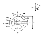
- FIG. 5 is a diagram corresponding to FIG. 5 in Modification 3.
- the liquid level detection device 100 As shown in FIG. 1, the liquid level detection device 100 according to the first embodiment of the present disclosure is mounted on an internal combustion engine of a vehicle and installed in an oil pan 1 as a container.
- the oil pan 1 is attached to the bottom surface of a cylinder block of an internal combustion engine, and stores engine oil as a liquid.
- the liquid level detection device 100 is in an environment where it can be subjected to, for example, an impact when a vehicle rides on a step, vibrations generated in an engine, and the like.
- the liquid level detection device 100 mainly includes a connector part 5, a main body part 7, and a wire 6.
- the connector part 5 is capable of liquid tightly closing the opening 1a provided on the side part of the oil pan 1 and can be fitted with a mating connector for electrical connection with an external on-vehicle device (for example, a combination meter). Is formed.
- the main body 7 is fixed to the oil pan 1 in the installed state of FIG.
- the main body 7 can detect the level LL of the engine oil stored in the oil pan 1.
- the wire 6 electrically connects the connector part 5 and the main body part 7, and is arranged, for example, over the bracket 3. In this way, the liquid level detection device 100 can output a detection signal from the main body portion 7 to the outside via the wire 6 and the connector portion 5.
- the main body 7 of the liquid level detection device 100 includes a float 10, a reed switch 20, terminals 30 and 34, a body 40, and a cover 50.
- the float 10 has a foam 12 and a magnet 14 and can float on the liquid level of the engine oil.
- the foam 12 is formed in a cylindrical shape by a material having a specific gravity smaller than that of engine oil such as foamed phenol resin.
- An annular holding groove 12 a is formed on the inner peripheral side of the foam 12.
- the magnet 14 is a permanent magnet such as a ferrite magnet, and is formed in a cylindrical shape. The magnet 14 is held in the foam 12 by being fitted in the holding groove 12a.
- the reed switch 20 is a detection element that detects the position of the float 10.
- the reed switch 20 includes a glass tube 22 formed in a cylindrical shape, and a pair of leads 24 and 25 extending from both ends of the glass tube 22 in a band shape.
- the glass tube 22 is a hollow cylindrical glass tube, and accommodates the opposing portions which are the ends of the leads 24 and 25 in a liquid-tight manner.
- Each facing portion is provided so as to be able to bend, and faces each other with a predetermined interval.
- the opposing portions come into contact with each other, and the reed switch 20 is turned on so that it can conduct between the leads 24 and 25.
- the reed switch 20 is turned off.
- the terminals 30 and 34 are formed by plating (for example, tin plating) on the surface of a conductor material such as brass.
- One terminal 30 is connected to one lead 24 of the reed switch 20 and to a ground wire (not shown).
- the other terminal 34 is connected to the other lead 25 and to the wire 6.
- the terminals 30 and 34 are fixed to the body 40 by, for example, insert molding to the body 40.
- the body 40 is provided integrally with the terminals 30 and 34, and is provided in a plate shape as a whole mainly made of synthetic resin such as polyphenylene sulfide (PPS) resin having excellent oil resistance.
- PPS polyphenylene sulfide
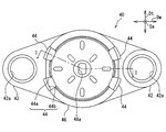
- the body 40 includes a flange portion 42, an engagement structure portion 44, and a base portion 46.
- the flange portion 42 is provided in a hook shape on the outside of the engagement structure portion 44 and the base portion 46.
- a mounting ring 42a formed in a cylindrical shape with metal is embedded in order to screw the main body portion 7 to the bracket 3.
- the engagement structure portion 44 is provided at a plurality of locations (for example, 4 locations) between the flange portion 42 and the base portion 46, and forms an engagement structure for engaging with the cover 50 described in detail later.
- the engagement structure 44 has a structure in which an engagement protrusion 44b is provided in the engagement hole 44a at each location.
- the base part 46 has a disk shape formed integrally with the flange part 42.
- the base portion 46 embeds a part of the terminal 30.
- the terminal 30 integrally includes a fixing portion 31 that is fixed by being embedded in the base portion 46 and an extending portion 32 that extends from the fixing portion 31.
- a part of the terminal 34 is embedded in the base portion 46 and is exposed on a surface of the base portion 46 that is opposite to the cover 50.
- the terminal 34 is connected to the lead 25 at this exposed portion.
- a through hole 46a that penetrates the cover 50 side and the exposed portion side is provided. By inserting the lead 25 into the through hole 46a, most of the reed switch 20 is a base. It is arranged closer to the cover 50 than the portion 46.
- the reed switch 20 is arranged to extend toward the cover 50 along the direction in which the through hole 46a is opened.
- an elongated plate-like extending portion 32 of the terminal 30 extends substantially parallel to the reed switch 20.
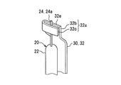
- stretching part 32 has the connection part 32a connected with the lead
- a clip plate 32c that can be bent in the width direction Dw and the plate thickness direction Dt of the extending portion 32 of the terminal 30 is provided integrally with the extending portion main body plate 32b at the distal end 32e of the extending portion 32.
- stretching part 32 is a direction orthogonal to the plane of the extending
- stretching part 32 is orthogonal to the plate
- the direction perpendicular to the longitudinal direction of the extending portion 32 that is, the axial direction Da of the central axis CA shown in FIG. 5).
- the leading end 24a of the lead 24 is sandwiched between the extending portion main body plate 32b and the sandwiching plate 32c from both sides in the plate thickness direction Dt. ing.
- the extending portion 32 and the reed switch 20 are electrically and mechanically connected by such a connecting portion 32a.
- the cover 50 is formed in a cylindrical shape as a whole by synthetic resin such as PPS resin, and is disposed to face the base portion 46 of the body 40.
- the cover 50 integrally includes an outer peripheral engaging portion 52, a cylindrical portion 54, and a pair of restricting portions 58.
- the outer peripheral engagement portion 52 is formed in a hollow cylindrical shape that opens to the body 40 side on the outermost peripheral side of the cover 50.
- the outer peripheral engaging portion 52 has engaging claws 52a at a plurality of locations (for example, four locations) on the body 40 side.
- the width of each engagement claw 52a is set smaller than the circumferential dimension of each corresponding engagement hole 44a.
- the cover 50 is held by the body 40 as each engaging claw 52a engages with each engaging protrusion 44b in the corresponding engaging hole 44a.
- the cylindrical portion 54 is formed in a hollow cylindrical shape having an opening on the body 40 side on the inner peripheral side with respect to the outer peripheral engaging portion 52 and a bottom surface 57 provided on the opposite side to the body 40. Since the body side opening 55 of the cylindrical portion 54 communicates with the through hole 46a, the direction in which the through hole 46a is opened and the axial direction Da of the central axis CA of the cylindrical portion 54 substantially match. In this way, the extending portion 32 of the reed switch 20 and the terminal 30 is disposed along the central axis CA in the cylindrical portion 54 with a gap from the inner wall 56 of the cylindrical portion 54.
- the float 10 is disposed in the space between the outer peripheral engaging portion 52 and the cylindrical portion 54.
- the float 10 moves up and down while being guided by the cylindrical portion 54 following the liquid level LL by being inserted into the cylindrical portion 54.
- the float 10 is restricted to move up and down within a predetermined range by contact with the body 40 or the cover 50.
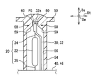
- a pair of regulating portions 58 are formed at positions facing the tip 32 e of the extending portion 32 inside the inner wall 56.
- the pair of restricting portions 58 are disposed to face each other, and an opposing gap FG is formed between the restricting portions 58.
- the facing gap FG is smaller than the inner diameter ID of the cylindrical portion 54 and larger than the plate thickness ET of the extending portion 32.
- stretching part 32 is arrange
- the plate thickness ET of the extending portion 32 is the thickness of the tip 32e of the extending portion 32 in the plate thickness direction Dt, more specifically, the thickness of the connecting portion 32a in the plate thickness direction Dt.
- the opposing gap FG is equal to the thickness of the extension portion main body plate 32b, the lead 24, in accordance with the connection portion 32a in which the lead 24 is sandwiched between the extension portion main body plate 32b and the sandwiching plate 32c from both sides.
- the thickness of the connecting portion 32a obtained by adding the thickness of the sandwiching plate 32c.
- the connecting portion 32 a including the lead 24 in the extending portion 32 is disposed in the facing gap FG of the restricting portion 58.
- Each restricting portion 58 of the present embodiment is provided in the shape of a protrusion that projects from the inner wall 56 of the cylindrical portion 54 toward the central axis CA so as to narrow the opposing gap FG.
- each regulating portion 58 is connected to the bottom surface 57 of the cylindrical portion 54 on the side opposite to the body 40.
- Each restricting portion 58 has an inclined surface 59 on the body 40 side. The inclined surface 59 is formed in a planar shape in which the distance from the central axis CA decreases (ie, approaches the central axis CA) as it faces the body 40 and toward the opposite side of the body 40.
- each restricting portion 58 has a flat opposed plane 60 that faces the extending portion 32.
- the opposing flat surfaces 60 are provided at positions where the central axis CA is sandwiched between them and where the opposing gap FG is minimum.
- Each opposing plane 60 extends along the width direction Dw so that the opposing gap FG between the opposing planes 60 has a substantially constant size at each location in the width direction Dw. Further, the length PL in the width direction Dw of the opposing plane 60 is smaller than the plate width EW of the extending portion 32.
- the side surfaces 61 on both sides of the width direction Dw connected to the facing plane 60 are inclined so as to move away from the central axis CA as the distance from the facing plane 60 increases. Thereby, on the outer side in the width direction Dw with respect to the facing plane 60, the facing gap FG between the corresponding side surfaces 61 increases as the distance from the central axis CA in the width direction Dw increases.
- a pair of enlarged spaces 62 formed by such enlargement is provided in the cylindrical portion 54 with the central axis CA sandwiched in the width direction Dw.
- the reed switch 20 is connected to the terminals 30 and 34. Specifically, before the connecting step, at the tip 32e of the extending portion 32 of the terminal 30 inserted into the body 40, the extending portion main body plate 32b and the sandwiching plate 32c are not bent and are integrated on the same plane. It is in a state of being lined up.
- the lead 24 of the reed switch 20 is disposed at the distal end 32e of the extending portion 32, and the sandwiching plate 32c is bent with respect to the extending portion main body plate 32b, whereby the lead 24 is formed between the extending portion main body plate 32b and the sandwiching plate 32c. Put in between.
- the reed switch 20 is connected to the terminal 30 by pressurization and energization, for example, by energization heat caulking, and the connection portion 32a is formed.
- One terminal 34 is also connected to the lead 25 of the reed switch 20 by, for example, energization heat caulking.
- the float 10 is inserted between the tube portion 54 and the outer peripheral engagement portion 52 of the cover 50.
- the extending portion 32 of the terminal 30 and the reed switch 20 are inserted into the cylindrical portion 54.
- the body 40 and the cover 50 are opposed to each other in a posture in which the extending direction (longitudinal direction) of the extending portion 32 and the axial direction Da of the cylindrical portion 54 are matched.
- the extending portion 32 and the reed switch 20 are inserted into the cylindrical portion 54 by moving the cover 50 toward the body 40 along the axial direction Da.
- the pair of regulating portions 58 in the cylindrical portion 54 face each other.
- the plate thickness direction Dt matches.
- the body side opening 55 of the cylinder portion 54 is just the base portion 46. It contacts the outer peripheral contour portion of the through hole 46a.
- the tip 32e (more specifically, the connecting portion 32a in the present embodiment) of the extending portion 32 in the cylindrical portion 54 is formed by the restricting portion 58 in a state of being sandwiched from both sides in the plate thickness direction Dt. It is arranged in the opposite gap FG.
- the liquid level LL of the liquid is detected by detecting the position of the float 10 that floats on the engine oil as the liquid by the reed switch 20 as the detection element.
- the terminal 30 to which the reed switch 20 is connected has a fixing portion 31 fixed to the body 40 and an elongated plate-like extending portion 32 extending from the fixing portion 31.
- the rigidity in the plate thickness direction Dt is lower than the rigidity in the width direction Dw. Therefore, the extension portion 32 is likely to bend and shake in the plate thickness direction Dt.
- the restricting portion 58 provided in the present disclosure is located at a position facing the tip 32e of the extending portion 32, and is opposed to each other, and the facing gap FG is smaller than the inner diameter ID of the cylindrical portion 54, and It is larger than the plate thickness ET of the extending portion 32.
- the extending portion 32 is disposed in the facing gap FG with the tip 32e sandwiched from both sides in the plate thickness direction Dt. For this reason, even if bending or vibration in the thickness direction Dt occurs in the extending portion 32 in accordance with the impact or vibration applied to the apparatus 100, the extending portion 32 is brought into contact with the restriction portion 58 by the tip 32e of the extending portion 32 coming into contact with the regulating portion 58. Displacement is regulated.
- the restricting portion 58 is provided in the cylindrical portion 54 in a protruding shape that protrudes from the inner wall 56 toward the central axis CA.
- the displacement of the extending portion 32 is easily restricted by the restricting portion 58 provided in such a protruding shape without impairing the strength of the cover 50. Therefore, the load on the reed switch 20 and the terminal 30 can be suppressed.
- the restricting portion 58 has the enlarged space 62 formed by enlarging as the facing gap FG is further away from the central axis CA in the width direction Dw. Even if the cover 50 is slightly rotated in the circumferential direction from the normal angle with respect to the body 40, the reed switch 20 and the terminal 30 during use or assembling, the plate thickness direction Dt The edges in the width direction Dw of the extending portion 32 sandwiched between the restricting portions 58 from both sides of the plate are difficult to contact the restricting portions 58. In this way, the extension part 32 and the reed switch 20 connected to the extension part 32 are less susceptible to torsional stress, so that the load on the reed switch 20 and the terminal 30 can be suppressed.
- the periphery of the restricting portion 58 can be thinned by the presence of the enlarged space 62, so that the performance degradation of the restricting portion 58 due to the occurrence of sink marks is suppressed. can do.
- the restricting portion 58 has a flat opposed plane 60 that faces the extending portion 32. Since the distal end 32e of the extending portion 32 comes into contact with the flat opposed flat surface 60, the stress received by the restricting portion 58 at the time of contact can be dispersed, and the restricting portion 58 can be prevented from being degraded due to wear or the like. .
- the restricting portion 58 has the inclined surface 59 in which the distance from the central axis CA decreases as it faces the body 40 and toward the opposite side of the body 40.
- the extending portion 32 is bent at the tip 32e and sandwiches the lead 24 corresponding to the connection terminal of the reed switch 20 from both sides, thereby connecting the reed switch 20 to the connecting portion. 32a, and the connecting portion 32a is disposed in the facing gap FG.
- the load to the reed switch 20 and the terminal 30 can be reliably suppressed by sandwiching the lead 24 and the extending portion 32 together.
- the second embodiment of the present disclosure is a modification of the first embodiment.
- the second embodiment will be described with a focus on differences from the first embodiment.
- the restricting portion 258 is formed by providing a notched groove on the bottom surface 57 of the cylindrical portion 54.
- the opposing flat surfaces 260 included in the pair of restricting portions 258 extend to both sides in the width direction Dw and reach the inner wall 56 of the cylindrical portion 54. Therefore, the opposing gap FG has a substantially constant size at each location in the width direction Dw.
- the extending portion 232 in the second embodiment is not connected to the reed switch 20 at the tip 232e of the extending portion 232. Specifically, as shown in FIG. 10, the extending portion 232 extends further to the opposite side of the body 40 than the connection portion with the reed switch 20. In addition, at the tip 232e of the extending portion 232, one extending portion main body plate 232b exists. In addition, in the connection location with the reed switch 20, the connection part 232a which pinches
- the extending portion 232 is disposed in the facing gap FG of the restricting portion 258 with the front end 232e in a state where the extending portion main body plate 232b is one sheet from both sides in the plate thickness direction Dt.
- the facing gap FG is smaller than the inner diameter ID of the cylindrical portion 54 and larger than the plate thickness ET of the extending portion main body plate 232b.
- the plate thickness (plate thickness of the extended portion 232) ET of the extended portion main body plate 232b is the thickness of the tip 232e of the extended portion 232 in the plate thickness direction Dt, more specifically, the extension in the plate thickness direction Dt. This is the thickness of the part main body plate 232b.
- the extending portion 232 extends to the opposite side of the body 40 from the connection point with the reed switch 20.
- the restricting portion 258 sandwiches only the extending portion 32, the size of the facing gap FG can be designed considering only the thickness tolerance of the extending portion 232. Therefore, the facing gap FG can be reduced and the performance of the restricting portion 258 can be improved.
- the bottom portion 57 is not provided in the cylindrical portion 54, and the extending portion 32 is arranged in the through-hole-like facing gap FG with the tip 232 e sandwiched therebetween. It may be.
- the restricting portion 58 has a flat plane 959 substantially perpendicular to the axial direction Da of the central axis CA, instead of the inclined surface 59 facing the body 40 side. May be.
- a curved opposing curved surface 960 that faces the extending portion 32 may be provided.
- the connecting portion 32a of the extending portion 32 may be connected to the lead 24 by a method other than energizing heat caulking such as soldering.
- the application target of the present disclosure is not limited to the detection of the engine oil liquid level LL.
- the present disclosure can be applied to a liquid level detection device in a container for other liquids mounted on the vehicle, such as brake fluid, engine coolant, and fuel.
- the present disclosure can be applied to a liquid level detection device in a container provided in various consumer devices and various transport devices, not limited to vehicles.
Landscapes
- Physics & Mathematics (AREA)
- Fluid Mechanics (AREA)
- General Physics & Mathematics (AREA)
- Level Indicators Using A Float (AREA)
Abstract
オイルパンに貯留されたエンジンオイルの液面レベルを検出する液面検出装置は、エンジンオイルに浮かぶフロートと、フロートの位置を検出するリードスイッチ(20)と、固定される固定部から延伸してリードスイッチ(20)と接続される細長板状の延伸部(32)を有するターミナル(30)と、固定部を固定するボデー(40)と、ボデー(40)側に開口する中空状の筒部(54)を有し、筒部(54)内において、リードスイッチ(20)及び延伸部(32)を配置するカバー(50)と、を備える。カバー(50)は、延伸部(32)の先端と対向する位置にあって、互いに対向配置されていて、その対向隙間(FG)が筒部(54)の内径よりも小さく、かつ延伸部(32)の板厚よりは大きい一対の規制部(58)を有する。延伸部(32)は、板厚方向(Dt)の両側から先端を挟んだ状態で規制部(58)の対向隙間(FG)に配置されている。
Description
本願は、2015年11月9日に出願された日本国特許出願第2015-219720号に基づくものであり、この開示をもってその内容を本明細書中に開示したものとする。
本開示は、容器に貯留された液体の液面レベルを検出する液面検出装置に関する。
従来、容器に貯留された液体の液面レベルを検出する液面検出装置が知られている。特許文献1に開示の液面検出装置は、液体に浮かぶフロートと、フロートの位置を検出する細長状の検出素子と、固定される固定部、及び、固定部から延伸して検出素子と接続される細長板状の延伸部を有するターミナルと、固定部を固定するボデーと、を備えている。さらに液面検出装置は、ボデー側に開口する中空状の筒部を有し、筒部内において、検出素子及び延伸部を、筒部の中心軸に沿って、かつ、前記筒部の内壁と隙間を空けた状態で配置するカバーと、さらに備えている。
ここで、ターミナルの延伸部先端は自由な状態となっているため、当該ターミナルは、所謂片持ち梁のような状態となっている。
しかしながら、液面検出装置に衝撃又は振動が加わることがある。このような衝撃又は振動により、所謂片持ち梁のような状態の細長板状の延伸部が撓んだり、振れたりする。したがって、例えば延伸部に接続された検出素子が筒部の内壁と接触すること、また例えばボデーに固定された固定部と延伸部との間に過度な応力負荷がかかること等、検出素子又はターミナルへの負荷が懸念されている。
本開示は、以上説明した問題に鑑みてなされたものであって、その目的は、検出素子又はターミナルへの負荷を抑制する液面検出装置を提供することにある。
本開示では、容器に貯留された液体の液面レベルを検出する液面検出装置であって、
液体に浮かぶフロートと、
フロートの位置を検出する検出素子と、
固定される固定部、及び、固定部から延伸して検出素子と接続される細長板状の延伸部を有するターミナルと、
固定部を固定するボデーと、
ボデー側に開口する中空状の筒部を有し、筒部内において、検出素子及び延伸部を、筒部の中心軸に沿って、かつ、筒部の内壁と隙間を空けた状態で配置するカバーと、を備え、
カバーは、延伸部の先端と対向する位置にあって、互いに対向配置されていて、その対向隙間が筒部の内径よりも小さく、かつ延伸部の板厚よりは大きい一対の規制部を有し、
延伸部は、前記延伸部の板厚方向の両側から前記先端を挟んだ状態で規制部の対向隙間に配置されている液面検出装置を提供する。
液体に浮かぶフロートと、
フロートの位置を検出する検出素子と、
固定される固定部、及び、固定部から延伸して検出素子と接続される細長板状の延伸部を有するターミナルと、
固定部を固定するボデーと、
ボデー側に開口する中空状の筒部を有し、筒部内において、検出素子及び延伸部を、筒部の中心軸に沿って、かつ、筒部の内壁と隙間を空けた状態で配置するカバーと、を備え、
カバーは、延伸部の先端と対向する位置にあって、互いに対向配置されていて、その対向隙間が筒部の内径よりも小さく、かつ延伸部の板厚よりは大きい一対の規制部を有し、
延伸部は、前記延伸部の板厚方向の両側から前記先端を挟んだ状態で規制部の対向隙間に配置されている液面検出装置を提供する。
この構成によると、検出素子が液体に浮かぶフロートの位置を検出することで、当該液体の液面レベルが検出される。この検出素子が接続されるターミナルは、ボデーに固定される固定部、及び当該固定部から延伸する細長板状の延伸部を有している。このようなターミナルの延伸部では、幅方向の剛性に対して板厚方向の剛性が低いため、当該延伸部において板厚方向の撓み及び振れが生じ易くなる。
本開示の規制部は、延伸部の先端と対向する位置にあって、互いに対向配置されていて、その対向隙間が筒部の内径よりも小さく、かつ延伸部の板厚よりは大きい。この対向隙間に、延伸部は、板厚方向の両側から先端を挟んだ状態で配置されている。このため、装置に加わった衝撃又は振動に従って、延伸部に板厚方向の撓み又は振れが生じようとしても、延伸部の先端が規制部と接触することで、延伸部の変位が規制される。このような規制部による変位の規制により、検出素子が筒部の内壁と接触すること、又は、固定部と延伸部との間に過度な応力負荷がかかることが抑制される。
以下、本開示の複数の実施形態を図面に基づいて説明する。なお、各実施形態において対応する構成要素には同一の符号を付すことにより、重複する説明を省略する場合がある。各実施形態において構成の一部分のみを説明している場合、当該構成の他の部分については、先行して説明した他の実施形態の構成を適用することができる。また、各実施形態の説明において明示している構成の組み合わせばかりではなく、特に組み合わせに支障が生じなければ、明示していなくても複数の実施形態の構成同士を部分的に組み合せることができる。
(第1実施形態)
本開示の第1実施形態による液面検出装置100は、図1に示すように、車両の内燃機関に搭載され、容器としてのオイルパン1内に設置されている。オイルパン1は、内燃機関のシリンダーブロックの底面に取り付けられ、液体としてのエンジンオイルを貯留している。液面検出装置100は、例えば車両が段差に乗り上げた場合の衝撃、また例えばエンジンに発生する振動等を受け得る環境にある。
本開示の第1実施形態による液面検出装置100は、図1に示すように、車両の内燃機関に搭載され、容器としてのオイルパン1内に設置されている。オイルパン1は、内燃機関のシリンダーブロックの底面に取り付けられ、液体としてのエンジンオイルを貯留している。液面検出装置100は、例えば車両が段差に乗り上げた場合の衝撃、また例えばエンジンに発生する振動等を受け得る環境にある。
液面検出装置100は、コネクタ部5、本体部7、及びワイヤ6を主として構成されている。コネクタ部5は、オイルパン1側部に設けられた開口1aを液密に塞ぐと共に、外部の車載機器(例えば、コンビネーションメータ等)と電気的な接続をとるための相手側コネクタと嵌合可能に形成されている。本体部7は、例えばブラケット3を介して、図1の設置状態においてオイルパン1に対して固定されている。そして、本体部7は、オイルパン1に貯留されたエンジンオイルの液面レベルLLを検出可能となっている。ワイヤ6は、コネクタ部5と本体部7とを電気的に接続しており、例えばブラケット3に這わせて配置されている。このようにして、液面検出装置100は、本体部7からの検出信号を、ワイヤ6及びコネクタ部5を介して、外部へ出力可能となっている。
以下、図1~5に基づいて、液面検出装置100の本体部7について詳細に説明する。液面検出装置100の本体部7は、フロート10、リードスイッチ20、ターミナル30,34、ボデー40、及びカバー50を備えている。
フロート10は、図1に示すように、発泡体12及びマグネット14を有しており、エンジンオイルの液面に浮かぶことが可能となっている。発泡体12は、例えば発泡させたフェノール樹脂等のエンジンオイルよりも比重の小さい材料によって円筒状に形成されている。発泡体12の内周側には、円環状の保持溝12aが形成されている。マグネット14は、例えばフェライト磁石等の永久磁石であり、円筒状に形成されている。そして、マグネット14は、保持溝12a内に内嵌されることにより、発泡体12に保持されている。
リードスイッチ20は、フロート10の位置を検出する検出素子である。リードスイッチ20は、円筒状に形成されたガラス管22、及びガラス管22の両端から帯線状に延出する一対のリード24,25を有している。具体的に、ガラス管22は、中空円筒状のガラス管であって、各リード24,25の端部である対向部を液密に収容している。各対向部は、撓み可能に設けられており、所定の間隔を開けて対向している。各対向部にマグネット14からの磁界が作用すると、各対向部は、異なる磁極に磁化することで、互いに引き合う。こうして各対向部が互いに接触することとなり、リードスイッチ20は、各リード24,25間において導通可能なオン状態となる。反対に、各リード24,25にマグネット14からの十分な磁界が作用しなければ、各対向部は互いに接触せず、リードスイッチ20はオフ状態となる。
ターミナル30,34は、黄銅等の導体材料の表面に、めっき(例えばスズめっき)を施すこと等により形成されている。一方のターミナル30は、リードスイッチ20の一方のリード24と接続されていると共に、アース線(図示しない)と接続されている。他方のターミナル34は、他方のリード25と接続されていると共に、ワイヤ6と接続されている。このような電気的接続により、リードスイッチ20の検出信号が外部に出力されるのである。
ここで、ターミナル30,34は、ボデー40に例えばインサート成形されることで、このボデー40に固定されている。こうしてボデー40は、ターミナル30,34と一体的に設けられ、例えば耐油性に優れたポリフェニレンサルファイド(PPS)樹脂等の合成樹脂を主体として、全体としては板状に設けられている。ボデー40は、図1,2に示すように、フランジ部42、係合構造部44、及びベース部46を有している。
フランジ部42は、係合構造部44及びベース部46の外側に鍔状に設けられている。フランジ部42には、本体部7をブラケット3にネジ止めするために、金属により円筒状に形成された取付リング42aが埋設されている。
係合構造部44は、フランジ部42とベース部46との間の複数箇所(例えば4箇所)に設けられ、後に詳述するカバー50と係合するための係合構造を形成している。具体的に係合構造部44は、各箇所において係合孔44aの中に係合突起44bが設けられた構造となっている。
ベース部46は、フランジ部42と一体的に形成される円板状を呈している。ベース部46は、ターミナル30の一部を埋設している。これによりターミナル30は、ベース部46に埋設されることで固定される固定部31、及び当該固定部31から延伸する延伸部32を一体的に有している。ターミナル34は、一部がベース部46に埋設されていると共に、ベース部46においてカバー50とは反対側となる面に露出している。この露出箇所において、ターミナル34は、リード25と接続されている。ベース部46の中央には、カバー50側と露出箇所側とを貫通する貫通孔46aが設けられており、リード25が当該貫通孔46aに挿通されることで、リードスイッチ20の大部分はベース部46よりもカバー50側に配置されている。
こうしたリードスイッチ20は、図1に示すように、貫通孔46aが開けられた方向に沿って、カバー50側に延伸して配置される。これと共に、ターミナル30の細長板状の延伸部32がリードスイッチ20と略平行に延伸している。そして、延伸部32は、図3に拡大して示すように、その先端32eにおいて、リードスイッチ20のカバー50側の先端であるリード24と接続される接続部32aを有している。具体的に、延伸部32の先端32eには、ターミナル30の延伸部32の幅方向Dw及び板厚方向Dtに折り曲げ可能な挟み板32cが延伸部本体板32bと一体的に設けられている。なお、延伸部32の板厚方向Dtとは、延伸部本体板32bの平面に直交する方向であり、延伸部32の幅方向Dwとは、延伸部32の板厚方向Dtに直交し、かつ、延伸部32の長手方向(即ち、図5に示す中心軸CAの軸方向Da)に直交する方向である。そして、挟み板32cが延伸部本体板32bに対して折り曲げられることにより、リード24の先端部24aは、延伸部本体板32bと挟み板32cとの間において、板厚方向Dtの両側から挟まれている。こうした接続部32aにより、電気的及び機械的に、延伸部32とリードスイッチ20とが接続されている。
カバー50は、図1,4,5に示すように、例えばPPS樹脂等の合成樹脂により、全体としては円筒状に形成され、ボデー40のベース部46と対向して配置されている。カバー50は、外周係合部52、筒部54、及び一対の規制部58を一体的に有している。外周係合部52は、カバー50において最も外周側において、ボデー40側に開口する中空円筒状に形成されている。外周係合部52は、ボデー40側の複数箇所(例えば4箇所)において係合爪52aを有している。各係合爪52aの幅は、対応する各係合孔44aの周方向の寸法よりも小さく設定されている。各係合爪52aが対応する各係合孔44a中の各係合突起44bと係合することで、カバー50はボデー40に保持されている。
筒部54は、外周係合部52よりも内周側において、ボデー40側に開口し、ボデー40とは反対側に底面57を設けた中空円筒状に形成されている。筒部54のボデー側開口部55が貫通孔46aと連通することで、貫通孔46aが開けられた方向と、筒部54の中心軸CAの軸方向Daとは、実質一致している。こうして、筒部54内には、リードスイッチ20及びターミナル30のうち延伸部32が、中心軸CAに沿って、かつ、筒部54の内壁56とは隙間を空けた状態で配置されている。
図1に示すように、外周係合部52と筒部54との間の空間には、フロート10が配置されている。フロート10は、筒部54に挿通されることにより、液面レベルLLに追従して、筒部54に案内されつつ、上下動する。また、フロート10は、ボデー40又はカバー50との接触により所定範囲に上下動を制限される。
規制部58は、図4~6に示すように、内壁56の内側において、延伸部32の先端32eと対向する位置に一対形成されている。一対の規制部58は、互いに対向配置され、当該規制部58間に対向隙間FGを形成している。特に図5に示すように、こうした対向隙間FGは、筒部54の内径IDよりも小さく、かつ、延伸部32の板厚ETよりは大きい寸法となっている。そして、延伸部32は、板厚方向Dtの両側から、その先端32eを挟んだ状態で規制部58の対向隙間FGに配置されている。なお、本実施形態における延伸部32の板厚ETとは、板厚方向Dtにおける延伸部32の先端32eの厚み、より具体的には、板厚方向Dtにおける接続部32aの厚みである。
特に本実施形態では、リード24が延伸部本体板32bと挟み板32cとに両側から挟まれた状態の接続部32aに合わせて、対向隙間FGは、延伸部本体板32bの板厚、リード24の厚み、及び挟み板32cの板厚を合算した接続部32aの厚みよりも大きい寸法となっている。そして、延伸部32にリード24を含めた接続部32aは、規制部58の対向隙間FGに配置されているのである。
ここで、規制部58の形状をより詳細に説明する。本実施形態の各規制部58は、筒部54の内壁56から中心軸CAに向かって、互いに対向隙間FGを狭めるように突出する突起状に設けられている。図6に示すように、各規制部58は、ボデー40とは反対側おいて、筒部54の底面57と接続されている。また、各規制部58は、ボデー40側において傾斜面59を有している。傾斜面59は、ボデー40側を向き、ボデー40とは反対側に向かう程、中心軸CAからの距離が縮小する(すなわち、中心軸CAに近づく)平面状に形成されている。
さらに各規制部58は、延伸部32と対向する平面状の対向平面60を有している。各対向平面60は、図5に示すように、互いに中心軸CAを挟む位置かつ、対向隙間FGが最小となる位置に設けられている。各対向平面60は、幅方向Dwに沿って延伸することで、当該対向平面60間の対向隙間FGは、当該幅方向Dwの各箇所において実質一定の寸法となっている。また、対向平面60の幅方向Dwの長さPLは、延伸部32の板幅EWよりも小さくなっている。
対向平面60に接続された幅方向Dw両側の側面61は、対向平面60から遠ざかる程、中心軸CAから遠ざかるように傾斜している。これにより、対向平面60よりも幅方向Dwの外側では、対応する側面61間の対向隙間FGは、中心軸CAから幅方向Dwに遠ざかる程、拡大している。このような拡大により形成された拡大空間62が、筒部54内において、中心軸CAを幅方向Dwに挟んで一対設けられている。
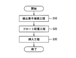
ここで、このような液面検出装置100の製造方法について、延伸部32を対向隙間FGに配置する方法を中心に、図7のフローチャートを用いて説明する。
最初に、検出素子接続工程では、リードスイッチ20をターミナル30,34と接続する。具体的に、接続工程前には、ボデー40にインサートされたターミナル30の延伸部32の先端32eにおいて、延伸部本体板32bと挟み板32cとは、折り曲げられておらず、同一平面上に一体に並んでいる状態となっている。ここで、リードスイッチ20のリード24を延伸部32の先端32eに配置し、挟み板32cを延伸部本体板32bに対して折り曲げることで、リード24を延伸部本体板32bと挟み板32cとの間に挟み込む。これと共に、例えば通電熱かしめによって加圧及び通電することで、リードスイッチ20はターミナル30と接続されて、接続部32aが形成されるのである。一方のターミナル34についても、例えば通電熱かしめによってリードスイッチ20のリード25と接続される。
次に、フロート配置工程では、カバー50の筒部54と外周係合部52との間に、フロート10を挿通する。
次に、挿入工程では、図8に示すように、ターミナル30の延伸部32及びリードスイッチ20を筒部54内に挿入する。具体的に、延伸部32の延伸方向(長手方向)と、筒部54の軸方向Daとを合わせた姿勢で、ボデー40とカバー50とを対向させる。そして、カバー50を軸方向Daに沿ってボデー40側に移動させることで、延伸部32及びリードスイッチ20を筒部54内に挿入する。
ここで、各4箇所のボデー40の係合構造部44と、カバー50の係合爪52aとの周方向の位置を合わせると、筒部54内の一対の規制部58が対向する方向と、板厚方向Dtとが合致するようになっている。
こうして、カバー50をボデー40側に移動させて、カバー50の係合爪52aとボデー40の係合突起44bとを係合させると、筒部54のボデー側開口部55は、丁度ベース部46の貫通孔46aの外周輪郭箇所に当接する。これと共に、筒部54内の延伸部32の先端32e(本実施形態では、より具体的には接続部32a)は、板厚方向Dtの両側から挟まれた状態で、規制部58により形成された対向隙間FGに配置されるのである。
(作用効果)
以上説明した第1実施形態の作用効果を以下に説明する。
以上説明した第1実施形態の作用効果を以下に説明する。
第1実施形態によると、検出素子としてのリードスイッチ20が液体としてのエンジンオイルに浮かぶフロート10の位置を検出することで、当該液体の液面レベルLLが検出される。このリードスイッチ20が接続されるターミナル30は、ボデー40に固定される固定部31、及び当該固定部31から延伸する細長板状の延伸部32を有している。このようなターミナル30の延伸部32では、幅方向Dwの剛性に対して板厚方向Dtの剛性が低いため、当該延伸部32において板厚方向Dtの撓み及び振れが生じ易くなる。
ここで本開示において設けられた規制部58は、延伸部32の先端32eと対向する位置にあって、互いに対向配置されていて、その対向隙間FGが筒部54の内径IDよりも小さく、かつ延伸部32の板厚ETよりは大きい。この対向隙間FGに、延伸部32は、板厚方向Dtの両側から先端32eを挟んだ状態で配置されている。このため、装置100に加わった衝撃又は振動に従って、延伸部32に板厚方向Dtの撓み又は振れが生じようとしても、延伸部32の先端32eが規制部58と接触することで、延伸部32の変位が規制される。このような規制部58による変位の規制により、リードスイッチ20が筒部54の内壁56と接触すること、又は、固定部31と延伸部32との間に過度な応力負荷がかかることが抑制される。また、第1実施形態によると、規制部58は、筒部54に内壁56から中心軸CAへ向かって突出する突起状に設けられる。このような突起状に設けられた規制部58により、カバー50の強度を損なうことなく、容易に延伸部32の変位が規制される。したがって、リードスイッチ20及びターミナル30への負荷を抑制することができる。
また、第1実施形態によると、規制部58は、対向隙間FGが中心軸CAから幅方向Dwに遠ざかる程、拡大することで形成された拡大空間62を有する。このような拡大空間62により、使用時又は組立時に、ボデー40、リードスイッチ20及びターミナル30に対して、カバー50が正規の角度から少し周方向に回転してしまったとしても、板厚方向Dtの両側から規制部58に挟まれた延伸部32における幅方向Dwの縁が規制部58に接触し難くなる。こうして、延伸部32と、当該延伸部32に接続されたリードスイッチ20がねじり応力を受け難くなることで、リードスイッチ20及びターミナル30への負荷を抑制することができる。
加えて、カバー50を例えば樹脂材料にて型成形して製造する場合では、拡大空間62の存在によって規制部58の周辺を薄肉化できるので、ヒケの発生等による規制部58の性能低下を抑制することができる。
また、第1実施形態によると、規制部58は、延伸部32と対向する平面状の対向平面60を有する。延伸部32の先端32eが平面状の対向平面60と接触するようになるので、接触時に規制部58が受ける応力が分散され、規制部58が摩耗等によって性能低下することを抑制することができる。
また、第1実施形態によると、規制部58は、ボデー40側を向き、ボデー40とは反対側に向かう程、中心軸CAからの距離が縮小する傾斜面59を有する。このような傾斜面59により、組立時においてリードスイッチ20及びターミナル30を筒部54に挿入する場合に、延伸部32の先端32eが中心軸CA側に案内されるので、スムーズな液面検出装置100の組立が可能となる。
また、第1実施形態によると、延伸部32は、その先端32eにおいて、折り曲げられてリードスイッチ20の接続端子に相当するリード24を両側から挟むことで、当該リードスイッチ20と接続される接続部32aを有し、接続部32aが対向隙間FGに配置されている。このようにリード24及び延伸部32がまとめて挟まれることで、確実にリードスイッチ20及びターミナル30への負荷を抑制することができる。
(第2実施形態)
図9~11に示すように、本開示の第2実施形態は第1実施形態の変形例である。第2実施形態について、第1実施形態とは異なる点を中心に説明する。
図9~11に示すように、本開示の第2実施形態は第1実施形態の変形例である。第2実施形態について、第1実施形態とは異なる点を中心に説明する。
第2実施形態では、図9,11に示すように、筒部54の底面57に切込み状の溝を設けることで、規制部258が形成されている。一対の規制部258が有する各対向平面260は、幅方向Dw両側に延伸して筒部54の内壁56まで到達している。したがって、対向隙間FGは、幅方向Dwの各箇所において実質一定の寸法となっている。
第2実施形態における延伸部232は、第1実施形態とは異なり、当該延伸部232の先端232eにてリードスイッチ20と接続されているわけではない。具体的に延伸部232は、図10に示すように、リードスイッチ20との接続箇所よりもボデー40とは反対側にさらに延伸している。そして、延伸部232の先端232eには、延伸部本体板232bが1枚存在する状態となっている。なお、リードスイッチ20との接続箇所においては、第1実施形態と同様にリード24を挟む接続部232aが設けられている。
延伸部232は、第1実施形態と同様に、板厚方向Dtの両側から、その延伸部本体板232bが1枚である状態の先端232eを挟んだ状態で規制部258の対向隙間FGに配置されている。そして、対向隙間FGは、筒部54の内径IDよりは小さく、かつ、延伸部本体板232bの板厚ETよりは大きい寸法となっている。本実施形態における延伸部本体板232bの板厚(延伸部232の板厚)ETとは、板厚方向Dtにおける延伸部232の先端232eの厚み、より具体的には、板厚方向Dtにおける延伸部本体板232bの厚みである。
このような第2実施形態によると、延伸部232は、リードスイッチ20との接続箇所よりもボデー40とは反対側に延伸する。このようにすることで、規制部258は、延伸部32のみを挟むこととなるため、対向隙間FGの寸法は、延伸部232の板厚公差だけを考慮して設計可能となる。したがって、当該対向隙間FGを小さくし、規制部258の性能を高めることができる。
(他の実施形態)
以上、本開示の複数の実施形態について説明したが、本開示は、それらの実施形態に限定して解釈されるものではなく、本開示の要旨を逸脱しない範囲内において種々の実施形態及び組み合わせに適用することができる。
以上、本開示の複数の実施形態について説明したが、本開示は、それらの実施形態に限定して解釈されるものではなく、本開示の要旨を逸脱しない範囲内において種々の実施形態及び組み合わせに適用することができる。
具体的に、変形例1としては、図12に示すように、筒部54に底面57を設けずに、貫通孔状の対向隙間FGに、延伸部32が先端232eを挟んだ状態で配置されていてもよい。
変形例2としては、図12に示すように、規制部58は、ボデー40側を向く傾斜面59の代わりに、中心軸CAの軸方向Daと実質垂直な平面状の平面959を有していてもよい。
変形例3としては、図13に示すように、対向平面60の代わりに、延伸部32と対向する曲面状の対向曲面960を有していてもよい。
変形例4としては、延伸部32が有する接続部32aは、例えば半田付け等の通電熱かしめ以外の方法によりリード24と接続されるものであってもよい。
変形例5としては、本開示の適用対象は、エンジンオイルの液面レベルLLの検出に限られない。車両に搭載される他の液体、例えばブレーキフルード、エンジン冷却水、燃料等の容器内の液面検出装置に本開示は適用可能である。さらに、車両用に限らず、各種民生用機器、各種輸送機器が備える容器内の液面検出装置に、本開示は適用可能である。
Claims (7)
- 容器(1)に貯留された液体の液面レベル(LL)を検出する液面検出装置であって、
前記液体に浮かぶフロート(10)と、
前記フロート(10)の位置を検出する検出素子(20)と、
固定される固定部(31)、及び、前記固定部(31)から延伸して前記検出素子(20)と接続される細長板状の延伸部(32,232)を有するターミナル(30)と、
前記固定部(31)を固定するボデー(40)と、
前記ボデー(40)側に開口する中空状の筒部(54)を有し、前記筒部(54)内において、前記検出素子(20)及び前記延伸部(32,232)を、前記筒部(54)の中心軸(CA)に沿って、かつ、前記筒部(54)の内壁(56)と隙間を空けた状態で配置するカバー(50)と、を備え、
前記カバー(50)は、前記延伸部(32,232)の先端(32e,232e)と対向する位置にあって、互いに対向配置されていて、その対向隙間(FG)が前記筒部(54)の内径(ID)よりも小さく、かつ前記延伸部(32,232)の板厚(ET)よりは大きい一対の規制部(58,258)を有し、
前記延伸部(32,232)は、前記延伸部(32,232)の板厚方向(Dt)の両側から前記先端(32e,232e)を挟んだ状態で前記規制部(58,258)の前記対向隙間(FG)に配置されている液面検出装置。 - 前記規制部(58,258)は、前記内壁(56)から前記中心軸(CA)へ向かって突出する突起状に設けられる請求項1に記載の液面検出装置。
- 前記規制部(58)において、前記対向隙間(FG)が前記中心軸(CA)から前記延伸部(32)の幅方向(Dw)に遠ざかる程、拡大することで形成された拡大空間(62)が設けられている請求項1又は2に記載の液面検出装置。
- 前記規制部(58,258)は、前記延伸部(32,232)と対向する平面状の対向平面(60,260)を有する請求項1から3のいずれか1項に記載の液面検出装置。
- 前記規制部(58,258)は、前記ボデー(40)側を向き、前記ボデー(40)とは反対側に向かう程、前記中心軸(CA)からの距離が縮小する傾斜面(59)を有する請求項1から4のいずれか1項に記載の液面検出装置。
- 前記延伸部(32)は、その先端(32e)において、折り曲げられて前記検出素子(20)の接続端子(24)を両側から挟むことで、前記検出素子(20)と接続される接続部(32a)を有し、
前記接続部(32a)が前記対向隙間(FG)に配置されている請求項1から5のいずれか1項に記載の液面検出装置。 - 前記延伸部(232)は、前記検出素子(20)との接続箇所よりも前記ボデー(40)とは反対側にさらに延伸する請求項1から5のいずれか1項に記載の液面検出装置。
Priority Applications (1)
| Application Number | Priority Date | Filing Date | Title |
|---|---|---|---|
| DE112016004529.8T DE112016004529T5 (de) | 2015-11-09 | 2016-10-04 | Flüssigkeitsniveauerfassungsvorrichtung |
Applications Claiming Priority (2)
| Application Number | Priority Date | Filing Date | Title |
|---|---|---|---|
| JP2015219720A JP6365508B2 (ja) | 2015-11-09 | 2015-11-09 | 液面検出装置 |
| JP2015-219720 | 2015-11-09 |
Publications (1)
| Publication Number | Publication Date |
|---|---|
| WO2017081957A1 true WO2017081957A1 (ja) | 2017-05-18 |
Family
ID=58695046
Family Applications (1)
| Application Number | Title | Priority Date | Filing Date |
|---|---|---|---|
| PCT/JP2016/079373 Ceased WO2017081957A1 (ja) | 2015-11-09 | 2016-10-04 | 液面検出装置 |
Country Status (3)
| Country | Link |
|---|---|
| JP (1) | JP6365508B2 (ja) |
| DE (1) | DE112016004529T5 (ja) |
| WO (1) | WO2017081957A1 (ja) |
Citations (6)
| Publication number | Priority date | Publication date | Assignee | Title |
|---|---|---|---|---|
| JPH0272937U (ja) * | 1988-11-23 | 1990-06-04 | ||
| JPH03101429U (ja) * | 1990-02-02 | 1991-10-23 | ||
| JPH0429838U (ja) * | 1990-07-03 | 1992-03-10 | ||
| JPH10281855A (ja) * | 1997-04-04 | 1998-10-23 | Nippon Vinylon Kk | フロート式液面計 |
| WO2010146823A1 (ja) * | 2009-06-15 | 2010-12-23 | ボッシュ株式会社 | 液面検出器およびこれを備えたリザーバタンク |
| JP2013002965A (ja) * | 2011-06-16 | 2013-01-07 | Denso Corp | 液面レベルセンサ |
Family Cites Families (2)
| Publication number | Priority date | Publication date | Assignee | Title |
|---|---|---|---|---|
| JP2014235157A (ja) | 2013-06-05 | 2014-12-15 | 株式会社デンソー | 液面検出装置 |
| JP5938065B2 (ja) | 2014-05-16 | 2016-06-22 | ソフトバンク株式会社 | 表示制御装置及びプログラム |
-
2015
- 2015-11-09 JP JP2015219720A patent/JP6365508B2/ja active Active
-
2016
- 2016-10-04 WO PCT/JP2016/079373 patent/WO2017081957A1/ja not_active Ceased
- 2016-10-04 DE DE112016004529.8T patent/DE112016004529T5/de active Pending
Patent Citations (6)
| Publication number | Priority date | Publication date | Assignee | Title |
|---|---|---|---|---|
| JPH0272937U (ja) * | 1988-11-23 | 1990-06-04 | ||
| JPH03101429U (ja) * | 1990-02-02 | 1991-10-23 | ||
| JPH0429838U (ja) * | 1990-07-03 | 1992-03-10 | ||
| JPH10281855A (ja) * | 1997-04-04 | 1998-10-23 | Nippon Vinylon Kk | フロート式液面計 |
| WO2010146823A1 (ja) * | 2009-06-15 | 2010-12-23 | ボッシュ株式会社 | 液面検出器およびこれを備えたリザーバタンク |
| JP2013002965A (ja) * | 2011-06-16 | 2013-01-07 | Denso Corp | 液面レベルセンサ |
Also Published As
| Publication number | Publication date |
|---|---|
| DE112016004529T5 (de) | 2018-06-21 |
| JP2017090206A (ja) | 2017-05-25 |
| JP6365508B2 (ja) | 2018-08-01 |
Similar Documents
| Publication | Publication Date | Title |
|---|---|---|
| JP5179295B2 (ja) | 温度センサの取付装置 | |
| CN113853837B (zh) | 电子控制装置 | |
| CN106533415B (zh) | 静电电容检测式压力开关 | |
| US10648878B2 (en) | Oil pressure sensor attachment structure | |
| JP6020360B2 (ja) | 液面検出装置 | |
| US6851315B2 (en) | Hermetic fuel level sender | |
| US11101718B2 (en) | Motor rotation detection device | |
| JP6011385B2 (ja) | 内燃機関用の点火コイル | |
| JP6597005B2 (ja) | 内燃機関用の点火コイル | |
| JP6123578B2 (ja) | 液面検出装置の製造方法 | |
| US20160341592A1 (en) | Flow rate detecting device for fuel tank | |
| US20180275006A1 (en) | Oil pressure sensor attachment structure | |
| JP5494091B2 (ja) | 液面検出装置の製造方法 | |
| JP6365508B2 (ja) | 液面検出装置 | |
| EP2585688B1 (en) | Sensor apparatus | |
| JP6555090B2 (ja) | 液面検出装置 | |
| CN109642658B (zh) | 非接触式抑制器开关 | |
| JP2013036886A (ja) | センサおよびその製造方法 | |
| WO2016088325A1 (ja) | 液面検出装置 | |
| US20180003541A1 (en) | Liquid surface detection apparatus and manufacturing method of same | |
| JP3724747B2 (ja) | 非接触式液面レベルセンサ | |
| JP6624544B2 (ja) | 近接センサ | |
| WO2015182109A1 (ja) | 液面検出装置 | |
| US20240208566A1 (en) | Vehicle steering device | |
| JP6344222B2 (ja) | 液面検出装置 |
Legal Events
| Date | Code | Title | Description |
|---|---|---|---|
| 121 | Ep: the epo has been informed by wipo that ep was designated in this application |
Ref document number: 16863921 Country of ref document: EP Kind code of ref document: A1 |
|
| WWE | Wipo information: entry into national phase |
Ref document number: 112016004529 Country of ref document: DE |
|
| 122 | Ep: pct application non-entry in european phase |
Ref document number: 16863921 Country of ref document: EP Kind code of ref document: A1 |