WO2017080189A1 - 液晶显示装置红粉拖色的显示控制方法及液晶显示装置 - Google Patents
液晶显示装置红粉拖色的显示控制方法及液晶显示装置 Download PDFInfo
- Publication number
- WO2017080189A1 WO2017080189A1 PCT/CN2016/084339 CN2016084339W WO2017080189A1 WO 2017080189 A1 WO2017080189 A1 WO 2017080189A1 CN 2016084339 W CN2016084339 W CN 2016084339W WO 2017080189 A1 WO2017080189 A1 WO 2017080189A1
- Authority
- WO
- WIPO (PCT)
- Prior art keywords
- liquid crystal
- control signal
- dimming
- frequency
- backlight
- Prior art date
- Legal status (The legal status is an assumption and is not a legal conclusion. Google has not performed a legal analysis and makes no representation as to the accuracy of the status listed.)
- Ceased
Links
Images




Classifications
-
- G—PHYSICS
- G09—EDUCATION; CRYPTOGRAPHY; DISPLAY; ADVERTISING; SEALS
- G09G—ARRANGEMENTS OR CIRCUITS FOR CONTROL OF INDICATING DEVICES USING STATIC MEANS TO PRESENT VARIABLE INFORMATION
- G09G3/00—Control arrangements or circuits, of interest only in connection with visual indicators other than cathode-ray tubes
- G09G3/20—Control arrangements or circuits, of interest only in connection with visual indicators other than cathode-ray tubes for presentation of an assembly of a number of characters, e.g. a page, by composing the assembly by combination of individual elements arranged in a matrix no fixed position being assigned to or needed to be assigned to the individual characters or partial characters
- G09G3/34—Control arrangements or circuits, of interest only in connection with visual indicators other than cathode-ray tubes for presentation of an assembly of a number of characters, e.g. a page, by composing the assembly by combination of individual elements arranged in a matrix no fixed position being assigned to or needed to be assigned to the individual characters or partial characters by control of light from an independent source
- G09G3/36—Control arrangements or circuits, of interest only in connection with visual indicators other than cathode-ray tubes for presentation of an assembly of a number of characters, e.g. a page, by composing the assembly by combination of individual elements arranged in a matrix no fixed position being assigned to or needed to be assigned to the individual characters or partial characters by control of light from an independent source using liquid crystals
Definitions
- the present invention relates to the field of liquid crystal display technology, and in particular, to a display control method for a red toner drag of a liquid crystal display device and a liquid crystal display device.
- the phosphor composition is the K2SiF6 ground state and the Mn4 + activated state chemical, wherein the response time of Mn 4+ is greater than 10 ms, relative to the nanosecond response of the blue chip and the ordinary YAG powder.
- Mn 4+ the response time of Mn 4+ is greater than 10 ms, relative to the nanosecond response of the blue chip and the ordinary YAG powder.
- the motion picture compensation technology controls the backlight to perform dimming and flicker at a certain frequency, that is, the backlight LED has a switching mode, and the red afterglow caused by the response delay of the Mn4+ acts on the moving picture, which may cause dragging, which affects the image quality effect.
- the main object of the present invention is to provide a display control method for a red toner dragging of a liquid crystal display device and a liquid crystal display device, which aim to solve the problem that in the motion picture compensation technology, the backlight is controlled to perform dimming and flicker at a certain frequency, that is, the backlight LED exists.
- the red afterglow caused by the response delay of Mn4+ acts on the moving picture, which may cause dragging, which affects the image quality effect.
- the present invention provides a display control method for red powder dragging of a liquid crystal display device, the liquid crystal display device comprising a liquid crystal panel and a backlight, the liquid crystal panel including a main control unit, and the backlight panel includes a light emitting unit And a backlight driving circuit, the liquid crystal display device red powder dragging display control method comprises the steps of:
- the main control unit outputs a backlight dimming control signal, where the backlight dimming control signal includes a backlight dimming control frequency;
- the backlight driving circuit outputs at least one dimming control signal according to the dimming control frequency in the backlight dimming control signal output by the main control unit, and periodically controls the lighting unit to emit light and extinguish according to the dimming control signal;
- the frequency of the dimming control signal is not synchronized with the frequency of the liquid crystal panel scanning screen.
- the frequency of the dimming control signal is greater than the frequency of the liquid crystal panel scanning screen.
- a difference between a frequency of the dimming control signal and a frequency of the liquid crystal panel scanning screen is greater than a preset frequency threshold, and the preset frequency threshold is 24 KHz.
- the frequency of the dimming control signal is not an integer multiple of the frequency of the liquid crystal panel scanning screen.
- the liquid crystal display device display control method further includes the steps of:
- the main control unit outputs a periodic control signal of the dimming signal
- the backlight driving circuit adjusts an active period of the dimming control signal according to a periodic control signal output by the main control unit to control brightness when the light emitting unit emits light.
- the liquid crystal display device display control method further includes the steps of:
- the main control unit When two or more dimming control signals are output, the main control unit outputs a dimming phase control signal, so that each dimming control signal controls the lighting units to alternately emit light and extinguish according to different timings.
- the present invention further provides a liquid crystal display device for controlling red toner drag, comprising:
- the liquid crystal display panel includes a main control unit for outputting a backlight dimming control signal, and the backlight dimming control signal includes a backlight dimming control frequency;
- a backlight board comprising a light emitting unit and a backlight driving circuit
- the backlight driving circuit is configured to output at least one dimming control signal according to a dimming control frequency in a backlight dimming control signal output by the main control unit, and periodically control the lighting unit to emit light according to the dimming control signal Extinguished
- the frequency of the dimming control signal is not synchronized with the frequency of the liquid crystal panel scanning screen.
- the frequency of the dimming control signal is greater than the frequency of the liquid crystal panel scanning screen.
- a difference between a frequency of the dimming control signal and a frequency of the liquid crystal panel scanning screen is greater than a preset frequency threshold, and the preset frequency threshold is 24 KHz.
- the frequency of the dimming control signal is not an integer multiple of the frequency of the liquid crystal panel scanning screen.
- the main control unit outputs a periodic control signal of the dimming signal; the backlight driving circuit adjusts an active period of the dimming control signal according to the periodic control signal output by the main control unit to control the light emitting unit.
- the main control unit when two or more dimming control signals are output, the main control unit outputs a dimming phase control signal, so that each dimming control signal controls the lighting units to alternately emit light and extinguish according to different timings.
- the invention is not synchronized with the scanning frequency of the liquid crystal panel, that is, the dimming phase of the backlight is not synchronized with the rotating phase of the liquid crystal molecules, and the afterglow effect of the new red powder appears for each cycle of the liquid crystal molecule rotation period.
- the time points are all changing.
- the backlight will be controlled at a certain frequency. Dimming flashing, that is, the backlight LED has a switching mode, and the red afterglow caused by the response delay of Mn4+ acts on the moving picture, which may cause dragging, which affects the image quality effect.
- the red afterglow caused by the response delay of Mn4+ is improved to cause dragging in the moving picture, thereby improving the image quality of the liquid crystal panel display.
- FIG. 1 is a schematic structural view of a preferred embodiment of a liquid crystal display device for controlling red toner dragging according to the present invention
- FIG. 2 is a schematic diagram of a curve on both sides of a motion switching in a backlight steady light mode
- FIG. 3 is a schematic diagram of the smear appearing in the backlight in the light and dark dimming mode
- Figure 4 is a schematic diagram showing the brightness curve of the smear of the new red powder LED
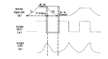
- FIG. 5 is a schematic diagram of a single pixel timing sequence of a conventional backlight dimming frequency and an Open Cell scanning frequency
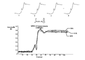
- RGB luminance variation curves in a conventional backlight and Open Cell scanning frequency design
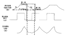
- FIG. 7 is a schematic diagram of a single pixel point timing design of a backlight dimming frequency and an Open Cell scanning frequency according to the present invention
- FIG. 8 is a schematic diagram of a RGB luminance variation curve in a backlight and Open Cell scanning frequency design according to the present invention.
- FIG. 9 is a schematic diagram of functional modules of a first embodiment of a display control method for red toner dragging of a liquid crystal display device according to the present invention.
- FIG. 10 is a schematic diagram of functional modules of a second embodiment of a display control method for a liquid crystal display device according to the present invention.
- the main solution of the embodiment of the present invention is: the main control unit outputs a backlight dimming control signal, the backlight dimming control signal includes a backlight dimming control frequency; and the backlight driving circuit is configured according to the backlight dimming control signal output by the main control unit.
- the dimming control frequency outputs at least one dimming control signal, and the dimming control signal periodically controls the lighting unit to emit light and extinguish; wherein the frequency of the dimming control signal is not synchronized with the frequency of the liquid crystal panel scanning screen .
- the afterglow effect of the new red powder is the time of occurrence of each period in the rotation period of the liquid crystal molecules. Points are all changing.
- the backlight will be controlled to perform dimming and flicker at a certain frequency, that is, the backlight LED has a switching mode, and the red afterglow caused by the response delay of Mn4+ acts on the moving picture, which may cause dragging, affecting the drawing.
- the problem of quality effects The red afterglow caused by the response delay of Mn4+ is improved to cause dragging in the moving picture, thereby improving the image quality of the liquid crystal panel display.
- the backlight is controlled to perform dimming and blinking at a certain frequency, that is, the backlight LED There is a switch mode, and the red afterglow caused by the response delay of Mn4+ acts on the moving picture, which may cause dragging, which affects the image quality effect.
- the present invention further provides a liquid crystal display device for controlling red toner drag.
- FIG. 1 is a schematic structural diagram of an embodiment of a liquid crystal display device for controlling red toner dragging according to the present invention.
- the liquid crystal display device for controlling red toner dragging includes a liquid crystal panel and a backlight panel, and the pixel unit 110 of the x rows and y columns is arranged on the array substrate 100 of the liquid crystal display panel.
- the backlight panel includes a plurality of sets of light emitting units 210, and each set of light emitting units 210 corresponds to a plurality of rows of pixel units 110 of the array substrate 100.
- the liquid crystal display panel further includes a panel driving circuit such as a timing control unit 120, a scan driving unit 130, a data driving unit 140, and a main control unit 150 such as an MCU processor; the backlight further includes a backlight driving circuit electrically connected to the light emitting unit 210. 220. among them:
- the input end of the timing control unit 120 is electrically connected to the main control unit 150, and the output end is electrically connected to the scan driving unit 130, the data driving unit 140 and the backlight driving circuit 220 for receiving the control signal sent by the main control unit 150, and according to the control.
- the signal output picture refresh signal S sync is supplied to the scan driving unit 130, the data driving unit 140, and the backlight driving circuit 220 to coordinate the operation of each circuit unit to drive the liquid crystal molecules to rotate and refresh the screen of the liquid crystal panel screen.
- the scan driving unit 130 receives the picture refresh signal S sync and outputs the scan signals S scan 1 to S scan m in time series, and turns on the switching elements of the pixel units 110 of 1 to m rows from top to bottom.
- the data driving unit 140 receives the picture refresh signal S sync and writes the data signals S data 1 to S data n carrying the picture information to the corresponding pixels when the scan driving unit 130 turns on a certain row of pixel units 110 in 1 to m rows.
- Unit 110 The backlight driving unit 220 is not only electrically connected to the timing control unit 120, but also receives the picture refresh signal S sync , and is also electrically connected to the main control unit 150, and receives the cycle control signal S duty and the frequency control signal S f sent by the main control unit 150, and
- the dimming control signals S dim 1 to S dimn are outputted according to the received periodic control signal S duty and the frequency control signal S f for periodically driving the operation of the light emitting unit 210.
- the period control signal S duty is used to control the duty cycle of S dim 1 to S dim n of the dimming control signal
- the frequency control signal S f is used to control the output frequency of the dimming control signals S dim 1 to S dim n , that is, Backlight dimming frequency.
- the main control unit 150 outputs a backlight dimming control signal, where the backlight dimming control signal includes a backlight dimming control frequency;
- the image signal is received, and the image signal is displayed according to the image signal and through the liquid crystal panel of the electronic terminal product.
- image In the process of displaying the image by the liquid crystal panel, the main control unit 150 outputs a backlight dimming control signal, and the backlight dimming control signal includes a backlight dimming control frequency.
- the electronic terminal product includes an electronic terminal product having a liquid crystal display panel such as a mobile phone, a pad or a notebook computer.
- the main control unit 150 outputs the backlight dimming control signal to the backlight driving circuit 220 electrically connected thereto.
- the backlight driving circuit 220 performs dimming control according to a backlight dimming control signal output by the main control unit 150. Frequency-outputting at least one dimming control signal, and periodically controlling the light-emitting unit to emit light and extinguish according to the dimming control signal;
- the frequency of the dimming control signal is not synchronized with the frequency of the liquid crystal panel scanning screen.
- the backlight driving circuit 220 receives the backlight dimming control signal output by the main control unit 150, and after receiving the backlight dimming control signal, according to the backlight dimming control signal output by the main control unit 150
- the light control frequency outputs at least one dimming control signal, and periodically controls the light emitting unit 210 to emit light and extinguish according to the dimming control signal; wherein, the frequency of the dimming control signal is not synchronized with the frequency of the liquid crystal panel scanning screen, Avoid red toner dragging of the liquid crystal display device.
- the frequency of the dimming control signal is A
- the frequency of the liquid crystal panel scanning screen is B
- Red powder high color gamut technology and movement motion compensation function corresponding single pixel timing, because the backlight dimming frequency is not synchronized with the liquid crystal panel scanning frequency, that is, the dimming phase of the backlight is not synchronized with the rotating phase of the liquid crystal molecules, the new red powder
- the afterglow effect changes the time point at which each liquid crystal molecule rotates in each cycle.
- the frequency of the dimming control signal is greater than the frequency of the liquid crystal panel scanning screen.
- the frequency of the dimming control signal is not synchronized with the frequency of the liquid crystal panel scanning screen, the afterglow effect can be improved, and when the frequency of the dimming control signal is greater than the frequency of the liquid crystal panel scanning screen, Good improvement afterglow effect.
- a difference between a frequency of the dimming control signal and a frequency of the liquid crystal panel scanning screen is greater than a preset frequency threshold.
- the preset frequency threshold is preferably 24 kHz, and the afterglow effect can be further improved when the difference between the frequency of the dimming control signal and the frequency of the liquid crystal panel scanning screen is greater than 24 kHz.
- the preset frequency threshold may also be a frequency value greater than 24 kHz. According to user requirements or performance settings of the electronic terminal product, if not set, the preset frequency threshold is 24 kHz.
- the frequency of the dimming control signal is not an integer multiple of the frequency of the liquid crystal scanning screen.
- the dimming frequency of the backlight is not synchronized with the scanning frequency of the liquid crystal panel, that is, the dimming phase of the backlight is not synchronized with the rotational phase of the liquid crystal molecules, and the afterglow effect of the new red powder is for each period of the liquid crystal molecule rotation period.
- the time points that appear are all changing.
- the backlight will be controlled to perform dimming and flicker at a certain frequency, that is, the backlight LED has a switching mode, and the red afterglow caused by the response delay of Mn4+ acts on the moving picture, which may cause dragging, affecting the drawing.
- the problem of quality effects The red afterglow caused by the response delay of Mn4+ is improved to cause dragging in the moving picture, thereby improving the image quality of the liquid crystal panel display.
- the main control unit 150 outputs a periodic control signal of the dimming signal
- the backlight driving circuit 220 adjusts an active period of the dimming control signal according to the periodic control signal output by the main control unit 150 to control the brightness when the light emitting unit 210 emits light.
- the main control unit 150 outputs a periodic control signal of the dimming signal when outputting the backlight dimming control signal, and the periodic control signal is used to control the action period of the dimming control signal.
- the periodic control signal includes a periodic control time, that is, a duty cycle of controlling the dimming control signal according to the periodic control time.
- the main control unit 150 sends a periodic control signal to the backlight driving circuit 220 electrically connected thereto, and the backlight driving circuit 220 receives the periodic control signal output by the main control unit, and the backlight driving circuit 220 according to the The periodic control signal output by the main control unit adjusts the active period of the dimming control signal to control the brightness when the light emitting unit emits light.
- the main control unit 150 when two or more dimming control signals are output, the main control unit 150 outputs a dimming phase control signal, so that each dimming control signal controls the lighting unit according to different timings. 210 turns to light and extinguish. The lighting timing of the light emitting unit 210 is controlled by the dimming phase control signal, thereby more effectively controlling the display of the liquid crystal panel.
- the main control unit 150 sends a periodic control signal to the backlight driving unit 220 to periodically adjust the active period of the dimming control signal to control the brightness when the light emitting unit 210 emits light.
- the display effect of the liquid crystal panel is better controlled by controlling the brightness of the light emitting unit 210 while solving the problem of the afterglow drag.
- T is the entire change cycle time.
- the generated curve is smooth, which is reflected in the liquid crystal display, and the image quality is clear.
- Figure 3 shows the synchronous response timing of the blue chip, green and red phosphor in the white LED when the backlight is in the light and dark dimming mode. Due to the afterglow effect of the new red powder, hysteresis will occur in the timing response, and the red smear problem will appear in the application.
- Figure 4 is a graph showing the brightness change of the red smear of the new red powder LED; when the backlight is turned off, the blue chip and the green phosphor react rapidly at the nanometer-level response speed, and the new red powder has a response time of more than 10 ms due to the response time. The two are inconsistent. It can be clearly seen from the figure that the brightness of blue and green has decreased, but the red brightness remains. This phenomenon is reflected in the liquid crystal display, which will produce a red smear.
- the brightness change function changes.
- Figure 6 shows the traditional backlight and Open Cell scanning frequency design, equipped with new red powder high color gamut technology and movement motion compensation function, using MPRT instrument to test the moving picture switching process, singular averaging RGB brightness curve of single pixel point S ( S>20). Since the generation of the residual effect of the new red powder is fixed phase for the liquid crystal rotation period, S periodic brightness change functions can be obtained from Equation 0 and Equation 6.
- Equation 8 the brightness change curve changes with time, and is affected by three factors of K2, K3, and K4, and the change curve is not a smooth transition. It can be clearly observed from the integral curve of the MPRT measurement that there are inflection points of the three primary colors of RGB, and R and the GB curve deviate, which is the cause of the liquid crystal display drag.
- Figure 8 shows the new backlight dimming frequency and Open Cell scanning frequency design, equipped with new red powder high color gamut technology and movement motion compensation function, using MPRT instrument to test the motion picture switching process, RGB brightness of a single pixel point S period integral average Change curve (S>20). Due to the rotation period of each liquid crystal molecule, the time points of the afterglow effect of the new red powder are random. For the integration of S cycles, the relative phase is not fixed due to the afterglow effect. From Equation 0 and Equation 6, and according to the discrete superposition principle, the brightness variation function of S cycles is feasible.
- Equation 10 It can be obtained from Equation 10 that the brightness change curve changes with time and is only affected by the K1 factor, that is, the brightness curve of the entire integral will be relatively smooth transition; that is, the drag effect generated by the afterglow effect is dispersed at each phase point. From the liquid crystal display, the liquid crystal drag phenomenon is diluted, and the human eye cannot recognize it. Obvious from the integral curve of MPRT measurement It is observed that there are no inflection points in the three primary colors of RGB, and the RGB three primary color curves are highly coincident, and there is no dragging phenomenon.
- the application of asynchronous design of backlight dimming and Open Cell scanning is introduced into the new red powder high color gamut liquid crystal display, and combined with the superposition principle of liquid crystal display, the liquid crystal display discrete superposition can effectively overcome the afterglow characteristics of the new red powder material itself.
- the new red powder LED achieves high color gamut technology and can be widely used in liquid crystal display.
- the present invention also proposes a liquid crystal display device including the liquid crystal display device display control device as described above.
- the liquid crystal display device controls the frequency of the dimming control signal to be not a multiple of the frequency at which the liquid crystal panel scans the screen.
- the red afterglow caused by the response delay of Mn4+ is improved to cause dragging in the moving picture, thereby improving the image quality of the liquid crystal panel display.
- the invention provides a display control method for red powder dragging of a liquid crystal display device.
- FIG. 9 is a schematic flow chart of a first embodiment of a display control method for red toner dragging of a liquid crystal display device according to the present invention.
- the display control method of the red powder drag of the liquid crystal display device includes:
- Step S10 the main control unit outputs a backlight dimming control signal, where the backlight dimming control signal includes a backlight dimming control frequency;
- the image signal is received, and the image signal is displayed according to the image signal and through the liquid crystal panel of the electronic terminal product.
- image In the process of displaying the image by the liquid crystal panel, the main control unit outputs a backlight dimming control signal, and the backlight dimming control signal includes a backlight dimming control frequency.
- the electronic terminal product includes an electronic terminal product having a liquid crystal display panel such as a mobile phone, a pad or a notebook computer.
- the main control unit outputs the backlight dimming control signal to a backlight driving circuit electrically connected thereto.
- step S20 the backlight driving circuit outputs at least one dimming control signal according to the dimming control frequency in the backlight dimming control signal output by the main control unit, and periodically controls the lighting unit to emit light and extinguish according to the dimming control signal;
- the frequency of the dimming control signal is not synchronized with the frequency of the liquid crystal panel scanning screen.
- the backlight driving circuit receives the backlight dimming control signal output by the main control unit, and after receiving the backlight dimming control signal, according to the dimming control frequency in the backlight dimming control signal output by the main control unit Outputting at least one dimming control signal, periodically controlling the illumination unit to emit light and extinguish according to the dimming control signal; wherein, the frequency of the dimming control signal is not synchronized with the frequency of the liquid crystal panel scanning screen to avoid the liquid crystal display device The red powder drags.
- the frequency of the dimming control signal is A
- the frequency of the liquid crystal panel scanning screen is B
- Red powder high color gamut technology and movement motion compensation function corresponding single pixel timing, because the backlight dimming frequency is not synchronized with the liquid crystal panel scanning frequency, that is, the dimming phase of the backlight is not synchronized with the rotating phase of the liquid crystal molecules, the new red powder Afterglow effect for liquid crystal molecules rotating in every cycle The time points within which they appear are all changing.
- the frequency of the dimming control signal is greater than the frequency of the liquid crystal panel scanning screen.
- the frequency of the dimming control signal is not synchronized with the frequency of the liquid crystal panel scanning screen, the afterglow effect can be improved, and the frequency of the dimming control signal is better when the frequency of the liquid crystal panel scan screen is greater than Improve the afterglow effect.
- a difference between a frequency of the dimming control signal and a frequency of the liquid crystal panel scanning screen is greater than a preset frequency threshold.
- the preset frequency threshold is preferably 24 kHz, and the afterglow effect can be further improved when the difference between the frequency of the dimming control signal and the frequency of the liquid crystal panel scanning screen is greater than 24 kHz.
- the preset frequency threshold may also be a frequency value greater than 24 kHz. According to user requirements or performance settings of the electronic terminal product, if not set, the preset frequency threshold is 24 kHz.
- the frequency of the dimming control signal is not an integer multiple of the frequency of the liquid crystal scanning screen.
- the dimming frequency of the backlight is not synchronized with the scanning frequency of the liquid crystal panel, that is, the dimming phase of the backlight is not synchronized with the rotational phase of the liquid crystal molecules, and the afterglow effect of the new red powder is for each period of the liquid crystal molecule rotation period.
- the time points that appear are all changing.
- the backlight will be controlled to perform dimming and flicker at a certain frequency, that is, the backlight LED has a switching mode, and the red afterglow caused by the response delay of Mn4+ acts on the moving picture, which may cause dragging, affecting the drawing.
- the problem of quality effects The red afterglow caused by the response delay of Mn4+ is improved to cause dragging in the moving picture, thereby improving the image quality of the liquid crystal panel display.
- FIG. 10 is a schematic flow chart of a second embodiment of a display control method for red toner dragging of a liquid crystal display device according to the present invention.
- the first embodiment of the display control method based on the red color drag of the liquid crystal display device, the method further includes:
- Step S30 the main control unit outputs a periodic control signal of the dimming signal
- Step S40 the backlight driving circuit adjusts an active period of the dimming control signal according to a periodic control signal output by the main control unit to control brightness when the light emitting unit emits light.
- the main control unit outputs a periodic control signal of the dimming signal when outputting the backlight dimming control signal, and the periodic control signal is used to control a duty cycle of the dimming control signal.
- the periodic control signal includes a periodic control time, that is, a duty cycle of controlling the dimming control signal according to the periodic control time.
- the periodic control signal is sent to a backlight driving circuit electrically connected thereto, the backlight driving circuit receiving a periodic control signal output by the main control unit, and the backlight driving circuit is periodically controlled according to the output of the main control unit The signal adjusts an action period of the dimming control signal to control brightness when the light emitting unit emits light.
- the main control unit when two or more dimming control signals are output, the main control unit outputs a dimming phase control signal, so that each dimming control signal controls the lighting unit to rotate according to different timings. Lights up and goes out. The light-emitting timing of the light-emitting unit is controlled by the dimming phase control signal, thereby more effectively controlling the display of the liquid crystal panel.
- the main control unit sends a periodic control signal to the backlight driving unit to periodically adjust the active period of the dimming control signal to control the brightness when the light emitting unit emits light. Therefore, while solving the problem of the afterglow drag, the display effect of the liquid crystal panel is better controlled by controlling the brightness of the light emitting unit.
- T is the entire change cycle time.
- the generated curve is smooth, which is reflected in the liquid crystal display, and the image quality is clear.
- Figure 3 shows the synchronous response timing of the blue chip, green and red phosphor in the white LED when the backlight is in the light and dark dimming mode. Due to the afterglow effect of the new red powder, hysteresis will occur in the timing response, and the red smear problem will appear in the application.
- Figure 4 is a graph showing the brightness change of the red smear of the new red powder LED; when the backlight is turned off, the blue chip and the green phosphor react rapidly at the nanometer-level response speed, and the new red powder has a response time of more than 10 ms due to the response time. The two are inconsistent. It can be clearly seen from the figure that the brightness of blue and green has decreased, but the red brightness remains. This phenomenon is reflected in the liquid crystal display, which will produce a red smear.
- the brightness change function changes.
- Figure 6 shows the traditional backlight and Open Cell scanning frequency design, equipped with new red powder high color gamut technology and movement motion compensation function, using MPRT instrument to test the moving picture switching process, singular averaging RGB brightness curve of single pixel point S ( S>20). Since the generation of the residual effect of the new red powder is fixed phase for the liquid crystal rotation period, S periodic brightness change functions can be obtained from Equation 0 and Equation 6.
- Equation 8 the brightness change curve changes with time, and is affected by three factors of K2, K3, and K4, and the change curve is not a smooth transition. It can be clearly observed from the integral curve of the MPRT measurement that there are inflection points of the three primary colors of RGB, and R and the GB curve deviate, which is the cause of the liquid crystal display drag.
- Figure 8 shows the new backlight dimming frequency and Open Cell scanning frequency design, equipped with new red powder high color gamut technology and movement motion compensation function, using MPRT instrument to test the motion picture switching process, RGB brightness of a single pixel point S period integral average Change curve (S>20). Due to the rotation period of each liquid crystal molecule, the time points of the afterglow effect of the new red powder are random. For the integration of S cycles, the relative phase is not fixed due to the afterglow effect. From Equation 0 and Equation 6, and according to the discrete superposition principle, the brightness variation function of S cycles can be obtained.
- Equation 10 It can be obtained from Equation 10 that the brightness change curve changes with time and is only affected by the K1 factor, that is, the brightness curve of the entire integral will be relatively smooth transition; that is, the drag effect generated by the afterglow effect is dispersed at each phase point. From the liquid crystal display, the liquid crystal drag phenomenon is diluted, and the human eye cannot recognize it. It can be clearly observed from the integral curve of the MPRT measurement that there is no inflection point in the RGB three primary colors, and the RGB three primary color curves are highly coincident, and there is no dragging phenomenon.
- the application of asynchronous design of backlight dimming and Open Cell scanning is introduced into the new red powder high color gamut liquid crystal display, and combined with the superposition principle of liquid crystal display, the liquid crystal display discrete superposition can effectively overcome the afterglow characteristics of the new red powder material itself.
- the new red powder LED achieves high color gamut technology and can be widely used in liquid crystal display.
Landscapes
- Engineering & Computer Science (AREA)
- Chemical & Material Sciences (AREA)
- Crystallography & Structural Chemistry (AREA)
- Physics & Mathematics (AREA)
- Computer Hardware Design (AREA)
- General Physics & Mathematics (AREA)
- Theoretical Computer Science (AREA)
- Liquid Crystal Display Device Control (AREA)
- Control Of Indicators Other Than Cathode Ray Tubes (AREA)
Abstract
一种液晶显示装置红粉拖色的显示控制方法及液晶显示装置显示控制装置,所述液晶显示装置包括液晶面板和背光板,所述液晶面板包括主控单元(150),所述背光板包括发光单元(210)和背光驱动电路(220),包括步骤:主控单元(150)输出背光调光控制信号,所述背光调光控制信号包括背光调光控制频率(S10);背光驱动电路(220)根据所述主控单元(150)输出的背光调光控制信号中的调光控制频率输出至少一个调光控制信号(Sdim1~Sdimn),根据所述调光控制信号(Sdim1~Sdimn)周期性的控制发光单元(210)发光、熄灭;其中,所述调光控制信号(Sdim1~Sdimn)的频率与液晶面板扫描屏幕的频率不同步(S20)。从而改善了拖色现象,进而提高了液晶面板显示的画质效果。
Description
本发明涉及液晶显示技术领域,尤其涉及液晶显示装置红粉拖色的显示控制方法及液晶显示装置。
随着液晶显示技术的发展以及消费市场对液晶显示产品显示画质的高要求,衍生出了高色域液晶显示技术。在实现高色域的技术方案中,采用蓝光芯片+新红粉(K2SiF6+Mn4+)是有效提升液晶显示色域,同时成本增加较少的一种方案。对于新红粉高色域液晶显示技术,由于其具有高色域特性,色彩表现出色,且在液晶显示技术中应用具有成本优势,已有部分液晶平板显示制造商引入生产。
然而,由于新红粉高色域LED中,荧光粉成分为K2SiF6基态和Mn4+激活态化学物,其中Mn4+的响应时间大于10ms,相对于蓝光芯片及普通YAG粉的纳秒级响应来说,Mn4+的响应会存在一个延迟。也就是说,LED在执行开关动作时,会产生红色余辉。目前,对于高阶画质的液晶显示,会搭配运动画面补偿功能,来实现超清晰超细腻的运动画面。运动画面补偿技术,会控制背光按一定频率进行调光闪烁,即背光LED存在开关模式,由于Mn4+的响应延迟导致的红色余辉作用于运动画面中会产生拖色现象,影响画质效果。
上述内容仅用于辅助理解本发明的技术方案,并不代表承认上述内容是现有技术。
发明内容
本发明的主要目的在于提供一种液晶显示装置红粉拖色的显示控制方法及液晶显示装置,旨在解决目前在运动画面补偿技术中,会控制背光按一定频率进行调光闪烁,即背光LED存在开关模式,由于Mn4+的响应延迟导致的红色余辉作用于运动画面中会产生拖色现象,影响画质效果的问题。
为实现上述目的,本发明提供的一种液晶显示装置红粉拖色的显示控制方法,所述液晶显示装置包括液晶面板和背光板,所述液晶面板包括主控单元,所述背光板包括发光单元和背光驱动电路,所述液晶显示装置红粉拖色的显示控制方法包括步骤:
主控单元输出背光调光控制信号,所述背光调光控制信号包括背光调光控制频率;
背光驱动电路根据所述主控单元输出的背光调光控制信号中的调光控制频率输出至少一个调光控制信号,根据所述调光控制信号周期性的控制发光单元发光、熄灭;
其中,所述调光控制信号的频率与液晶面板扫描屏幕的频率不同步。
优选地,所述调光控制信号的频率大于所述液晶面板扫描屏幕的频率。
优选地,所述调光控制信号的频率与所述液晶面板扫描屏幕的频率的差值大于预设频率阈值,所述预设频率阈值为24KHz。
优选地,所述调光控制信号的频率不为所述液晶面板扫描屏幕的频率的整数倍。
优选地,所述液晶显示装置显示控制方法,还包括步骤:
所述主控单元输出调光信号的周期性控制信号;
所述背光驱动电路根据所述主控单元输出的周期性控制信号调整所述调光控制信号的作用周期,以控制发光单元发光时的亮度。
优选地,所述液晶显示装置显示控制方法,还包括步骤:
在输出两个或两个以上的调光控制信号时,所述主控单元输出调光相位控制信号,以使各调光控制信号按照不同的时序控制发光单元轮流发光、熄灭。
此外,为实现上述目的,本发明还提供一种控制红粉拖色的液晶显示装置,包括:
液晶显示面板,包括用于输出背光调光控制信号的主控单元,所述背光调光控制信号包括背光调光控制频率;
背光板,包括发光单元和背光驱动电路;
所述背光驱动电路用于根据所述主控单元输出的背光调光控制信号中的调光控制频率输出至少一个调光控制信号,根据所述调光控制信号周期性的控制所述发光单元发光、熄灭;
其中,所述调光控制信号的频率与液晶面板扫描屏幕的频率不同步。
优选地,所述调光控制信号的频率大于所述液晶面板扫描屏幕的频率。
优选地,所述调光控制信号的频率与所述液晶面板扫描屏幕的频率的差值大于预设频率阈值,所述预设频率阈值为24KHz。
优选地,所述调光控制信号的频率不为所述液晶面板扫描屏幕的频率的整数倍。
优选地,所述主控单元输出调光信号的周期性控制信号;所述背光驱动电路根据所述主控单元输出的周期性控制信号调整所述调光控制信号的作用周期,以控制发光单元发光时的亮度。
优选地,在输出两个或两个以上的调光控制信号时,所述主控单元输出调光相位控制信号,以使各调光控制信号按照不同的时序控制发光单元轮流发光、熄灭。
本发明通过将调光频率与液晶面板扫描频率不同步,即背光的调光相位与液晶分子的旋转相位不同步,新红粉的余辉效应对于液晶分子旋转周期来说,在每一个周期内其出现的时间点都是变化的。有效避免目前在运动画面补偿技术中,会控制背光按一定频率进行
调光闪烁,即背光LED存在开关模式,由于Mn4+的响应延迟导致的红色余辉作用于运动画面中会产生拖色现象,影响画质效果的问题。改善了由于Mn4+的响应延迟导致的红色余辉作用于运动画面中会产生拖色现象,进而提高了液晶面板显示的画质效果。
图1为本发明控制红粉拖色的液晶显示装置较佳实施例的架构示意图;
图2为背光常亮模式下运动切换两侧曲线示意图;
图3为背光进行亮暗调光模式下出现拖影的示意图;
图4为新红粉LED出现拖影的亮度曲线示意图;
图5为传统的背光调光频率与Open Cell扫描频率设计单像素点时序示意图;
图6为传统的背光与Open Cell扫描频率设计中RGB亮度变化曲线示意图;
图7为本发明背光调光频率与Open Cell扫描频率设计单像素点时序示意图;
图8为本发明背光与Open Cell扫描频率设计中RGB亮度变化曲线示意图;
图9为本发明液晶显示装置红粉拖色的显示控制方法的第一实施例的功能模块示意图;
图10为本发明液晶显示装置显示控制方法的第二实施例的功能模块示意图。
本发明目的的实现、功能特点及优点将结合实施例,参照附图做进一步说明。
应当理解,此处所描述的具体实施例仅仅用以解释本发明,并不用于限定本发明。
本发明实施例的主要解决方案是:主控单元输出背光调光控制信号,所述背光调光控制信号包括背光调光控制频率;背光驱动电路根据所述主控单元输出的背光调光控制信号中的调光控制频率输出至少一个调光控制信号,据所述调光控制信号周期性的控制发光单元发光、熄灭;其中,所述调光控制信号的频率与液晶面板扫描屏幕的频率不同步。通过将调光频率与液晶面板扫描频率不同步,即背光的调光相位与液晶分子的旋转相位不同步,新红粉的余辉效应对于液晶分子旋转周期来说,在每一个周期内其出现的时间点都是变化的。有效避免目前在运动画面补偿技术中,会控制背光按一定频率进行调光闪烁,即背光LED存在开关模式,由于Mn4+的响应延迟导致的红色余辉作用于运动画面中会产生拖色现象,影响画质效果的问题。改善了由于Mn4+的响应延迟导致的红色余辉作用于运动画面中会产生拖色现象,进而提高了液晶面板显示的画质效果。
由于目前在运动画面补偿技术中,会控制背光按一定频率进行调光闪烁,即背光LED
存在开关模式,由于Mn4+的响应延迟导致的红色余辉作用于运动画面中会产生拖色现象,影响画质效果的问题。
基于上述问题,本发明进一步提供一种控制红粉拖色的液晶显示装置。
参照图1,图1为本发明控制红粉拖色的液晶显示装置的一实施例的架构示意图。
所述控制红粉拖色的液晶显示装置包括液晶面板和背光板,所述液晶显示面板的阵列基板100上排布有x行y列的像素单元110。所述背光板包括多组发光单元210,每一组发光单元210对应于阵列基板100的若干行像素单元110。此外,液晶显示面板还包括时序控制单元120、扫描驱动单元130、数据驱动单元140和如MCU处理器的主控单元150等面板驱动电路;背光板还包括与发光单元210电连接的背光驱动电路220。其中:
时序控制单元120的输入端与主控单元150电连接,输出端与扫描驱动单元130、数据驱动单元140和背光驱动电路220电连接,用以接收主控单元150发出的控制信号,并根据控制信号输出画面刷新信号Ssync给扫描驱动单元130、数据驱动单元140和背光驱动电路220,以协调各电路单元同步工作,驱动液晶分子转动刷新液晶面板屏幕的画面。
扫描驱动单元130接收画面刷新信号Ssync,并依时序输出扫描信号Sscan1至Sscanm,从上至下逐行地开启1至m行像素单元110的开关元件。
数据驱动单元140接收画面刷新信号Ssync,并在扫描驱动单元130开启1至m行中某一行像素单元110时,将载有画面信息的数据信号Sdata1至Sdatan写入对应的像素单元110。背光驱动单元220不仅与时序控制单元120电连接,接收画面刷新信号Ssync,而且还与主控单元150电连接,接收主控单元150发出的周期控制信号Sduty和频率控制信号Sf,并根据接收的周期控制信号Sduty和频率控制信号Sf输出调光控制信号Sdim1至Sdimn,用于周期性地依序驱动发光单元210工作。其中,周期控制信号Sduty用于控制调光控制信号的Sdim1至Sdimn的作用周期,频率控制信号Sf用于控制调光控制信号Sdim1至Sdimn的输出频率,即背光调光频率。
主控单元150输出背光调光控制信号,所述背光调光控制信号包括背光调光控制频率;
在本实施例中,在基于用户对电子终端产品的开机指令后,开启电子终端产品后,接收影像信号,根据所述影像信号并通过所述电子终端产品的液晶面板显示所述影像信号对应的图像。在所述液晶面板显示所述图像的过程中,主控单元150输出背光调光控制信号,所述背光调光控制信号包括背光调光控制频率。所述电子终端产品包括手机、pad或笔记本电脑等具有液晶显示面板的电子终端产品。所述主控单元150将所述背光调光控制信号输出至与其电连接的背光驱动电路220。
所述背光驱动电路220根据所述主控单元150输出的背光调光控制信号中的调光控制
频率输出至少一个调光控制信号,根据所述调光控制信号周期性的控制发光单元发光、熄灭;
其中,所述调光控制信号的频率与液晶面板扫描屏幕的频率不同步。
所述背光驱动电路220接收所述主控单元150输出的背光调光控制信号,在接收到所述背光调光控制信号后,根据所述主控单元150输出的背光调光控制信号中的调光控制频率输出至少一个调光控制信号,根据所述调光控制信号周期性的控制发光单元210发光、熄灭;其中,所述调光控制信号的频率与液晶面板扫描屏幕的频率不同步,以避免液晶显示装置的红粉拖色。即,例如,调光控制信号的频率为A,液晶面板扫描屏幕的频率为B,A≠N*B(N=1,2,3……),通过调整调光控制信号的频率,搭载新红粉高色域技术和机芯运动补偿功能,对应的单像素点时序,由于背光调光频率与液晶面板扫描频率不同步,即背光的调光相位与液晶分子的旋转相位不同步,新红粉的余辉效应对于液晶分子旋转来说,在每一个周期内其出现的时间点都是变化的。
优选地,所述调光控制信号的频率大于所述液晶面板扫描屏幕的频率。在所述调光控制信号的频率与所述液晶面板扫描屏幕的频率的不同步时,能改善余辉效果,在所述调光控制信号的频率大于所述液晶面板扫描屏幕的频率时,能更好的改善余辉效果。
进一步地,所述调光控制信号的频率与所述液晶面板扫描屏幕的频率的差值大于预设频率阈值。所述预设频率阈值优选为24KHz,在所述调光控制信号的频率与所述液晶面板扫描屏幕的频率的差值大于24KHz时,能更进一步地改善余辉效果。在本发明其他实施例中,所述预设频率阈值还可以是大于24KHz的频率数值,根据用户需求或者电子终端产品的性能设置,在未设置的情况下,所述预设频率阈值为24KHz。
进一步地,所述调光控制信号的频率不为所述液晶扫描屏幕的频率的整数倍。通过控制调光控制信号的频率不为所述液晶扫描屏幕的频率的整数倍,进一步提高控制红粉拖色的问题。
本实施例通过将调光频率与液晶面板扫描频率不同步,即背光的调光相位与液晶分子的旋转相位不同步,新红粉的余辉效应对于液晶分子旋转周期来说,在每一个周期内其出现的时间点都是变化的。有效避免目前在运动画面补偿技术中,会控制背光按一定频率进行调光闪烁,即背光LED存在开关模式,由于Mn4+的响应延迟导致的红色余辉作用于运动画面中会产生拖色现象,影响画质效果的问题。改善了由于Mn4+的响应延迟导致的红色余辉作用于运动画面中会产生拖色现象,进而提高了液晶面板显示的画质效果。
进一步地,所述主控单元150输出调光信号的周期性控制信号;
所述背光驱动电路220根据所述主控单元150输出的周期性控制信号调整所述调光控制信号的作用周期,以控制发光单元210发光时的亮度。
在本实施例中,所述主控单元150在输出背光调光控制信号时,输出调光信号的周期性控制信号,所述周期性控制信号用于控制所述调光控制信号的作用周期,所述周期性控制信号包括周期性控制时间,即,根据所述周期性控制时间控制所述调光控制信号的作用周期。所述主控单元150将周期性控制信号发送至与其电连接的背光驱动电路220,所述背光驱动电路220接收所述主控单元输出的周期性控制信号,所述背光驱动电路220根据所述主控单元输出的周期性控制信号调整所述调光控制信号的作用周期,以控制发光单元发光时的亮度。
在本发明一实施例中,在输出两个或两个以上的调光控制信号时,所述主控单元150输出调光相位控制信号,以使各调光控制信号按照不同的时序控制发光单元210轮流发光、熄灭。通过调光相位控制信号控制发光单元210的发光时序,从而更加有效的控制液晶面板的显示。
本实施例通过主控单元150发出周期性控制信号发送至背光驱动单元220以周期性调整所述调光控制信号的作用周期,以控制发光单元210发光时的亮度。使得在解决余辉拖色的问题的同时,通过控制发光单元210的亮度来更好的控制液晶面板的显示效果。
基于上述液晶显示装置显示控制的实施例,从如下过程描述本发明实施例所达到的效果:

图3为背光进行亮暗调光模式时,白光LED中蓝光芯片,绿色和红色荧光粉同步响应时序。由于新红粉的余辉效应,在时序响应上会产生滞后现象,应用上会出现红色拖影问题。
图4为新红粉LED出现红色拖影的亮度变化曲线图;在背光关闭瞬间,蓝光芯片和绿色荧光粉以纳米级响应速度迅速反应,而新红粉由于响应时间为大于10ms,会造成响应与前面两者不一致,从图中可明显观察到,蓝色和绿色的亮度已经下降,但红色亮度仍保持。此现象反应到液晶显示中,即会产生红色拖影。
由于背光进入亮暗切换的调光模式,且受新红粉的延迟响应作用,亮度变化函数产生变化。对于0≤t≤T/2区间,亮度变化函数 ---公式2;
对于T/2<t≤T区间,亮度变化函数Y3=Y4+Y5---公式3;其中 ---公式4,
 ---公式5,由公式即
对于整个周期T区间,亮度变化函数 ---公式6;
对于公式1和公式6,由Y1(0)=Y6(0),Y1(T)=Y6(T),可得K1=K2+K4+K5---公式7;
图5为传统的背光调光频率与Open Cell(液晶面板)扫描频率设计,A=N*B(N=1,2,3……),搭载新红粉高色域技术和机芯运动补偿功能,对应的单像素点时序图。由于背光调光相位与液晶分子旋转相位是同步的,新红粉的余辉效应对于液晶分子旋转周期来说,在每一个周期内其出现的时间点是固定的。
图6为传统的背光与Open Cell扫描频率设计,搭载新红粉高色域技术和机芯运动补偿功能,使用MPRT仪器测试运动画面切换过程,单个像素点S个周期积分平均的RGB亮度变化曲线(S>20)。由于新红粉余辉效应的产生对于液晶旋转周期来说都是固定相位的,由公式0和公式6可得S个周期亮度变化函数

即由公式8可得,亮度变化曲线随时间变化,受K2,K3,K4三个因子影响,变化曲线不是平滑过渡的。从MPRT量测的积分曲线中可明显观察到RGB三原色存在拐点,且R与GB曲线偏离,此为产生液晶显示拖色原因。
图7为新型的背光调光频率与Open Cell扫描频率设计,A>B+24HZ,且A≠N*B(N=1,2,3……),搭载新红粉高色域技术和机芯运动补偿功能,对应的单像素点时序图。由于新型背光调光频率与Open Cell扫描频率不同步,即背光的调光相位与液晶分子的旋转相位不同步;新红粉的余辉效应对于液晶分子旋转周期来说,在每一个周期内其出现的时间点都是变化的。
图8为新型的背光调光频率与Open Cell扫描频率设计,搭载新红粉高色域技术和机芯运动补偿功能,使用MPRT仪器测试运动画面切换过程,单个像素点S个周期积分平均的RGB亮度变化曲线(S>20)。由于每个液晶分子旋转周期内,新红粉的余辉效应产生时间点都是随机性的。对于S个周期的积分来说,由于余辉效应产生相对相位的不固定性,由公式0和公式6,再根据离散叠加原理,可行S个周期的亮度变化函数

由公式9和公式7可得

由公式10可得,亮度变化曲线随时间变化,只受K1因子影响,即整个积分的亮度曲线会是相对平滑过渡的;即余辉效应所产生的拖色现象被分散在每一个相位点上,从液晶显示上表现,液晶拖色现象被淡化,人眼无法识别。从MPRT量测的积分曲线中可明显
观察到RGB三原色不存在拐点,且RGB三原色曲线高度重合,不存在拖色现象。
通过把背光调光与Open Cell扫描的异步设计的应用引入到新红粉高色域液晶显示中,再结合液晶显示的叠加原理,实现液晶显示离散叠加,能够有效克服新红粉材料本身的余辉特性问题,使新红粉LED实现高色域技术能够广泛应用于液晶显示中。
基于上述液晶显示装置显示控制装置,本发明还提出一种液晶显示装置,所述液晶显示装置包括如上所述的液晶显示装置显示控制装置。所述液晶显示装置通过将调光控制信号的频率控制成不为液晶面板扫描屏幕的频率的倍数。改善了由于Mn4+的响应延迟导致的红色余辉作用于运动画面中会产生拖色现象,进而提高了液晶面板显示的画质效果。
本发明提供一种液晶显示装置红粉拖色的显示控制方法。
参照图9,图9为本发明液晶显示装置红粉拖色的显示控制方法的第一实施例的流程示意图。
在一实施例中,所述液晶显示装置红粉拖色的显示控制方法包括:
步骤S10,主控单元输出背光调光控制信号,所述背光调光控制信号包括背光调光控制频率;
在本实施例中,在基于用户对电子终端产品的开机指令后,开启电子终端产品后,接收影像信号,根据所述影像信号并通过所述电子终端产品的液晶面板显示所述影像信号对应的图像。在所述液晶面板显示所述图像的过程中,主控单元输出背光调光控制信号,所述背光调光控制信号包括背光调光控制频率。所述电子终端产品包括手机、pad或笔记本电脑等具有液晶显示面板的电子终端产品。所述主控单元将所述背光调光控制信号输出至与其电连接的背光驱动电路。
步骤S20,背光驱动电路根据所述主控单元输出的背光调光控制信号中的调光控制频率输出至少一个调光控制信号,根据所述调光控制信号周期性的控制发光单元发光、熄灭;其中,所述调光控制信号的频率与液晶面板扫描屏幕的频率不同步。
所述背光驱动电路接收所述主控单元输出的背光调光控制信号,在接收到所述背光调光控制信号后,根据所述主控单元输出的背光调光控制信号中的调光控制频率输出至少一个调光控制信号,根据所述调光控制信号周期性的控制发光单元发光、熄灭;其中,所述调光控制信号的频率与液晶面板扫描屏幕的频率不同步,以避免液晶显示装置的红粉拖色。即,例如,调光控制信号的频率为A,液晶面板扫描屏幕的频率为B,A≠N*B(N=1,2,3……),通过调整调光控制信号的频率,搭载新红粉高色域技术和机芯运动补偿功能,对应的单像素点时序,由于背光调光频率与液晶面板扫描频率不同步,即背光的调光相位与液晶分子的旋转相位不同步,新红粉的余辉效应对于液晶分子旋转来说,在每一个周期
内其出现的时间点都是变化的。
优选地,所述调光控制信号的频率大于所述液晶面板扫描屏幕的频率。在所述调光控制信号的频率与所述液晶面板扫描屏幕的频率不同步时,能改善余辉效果,在所述调光控制信号的频率大于所述液晶面板扫描屏幕的频率时,能更好的改善余辉效果。
进一步地,所述调光控制信号的频率与所述液晶面板扫描屏幕的频率的差值大于预设频率阈值。所述预设频率阈值优选为24KHz,在所述调光控制信号的频率与所述液晶面板扫描屏幕的频率的差值大于24KHz时,能更进一步地改善余辉效果。在本发明其他实施例中,所述预设频率阈值还可以是大于24KHz的频率数值,根据用户需求或者电子终端产品的性能设置,在未设置的情况下,所述预设频率阈值为24KHz。
进一步地,所述调光控制信号的频率不为所述液晶扫描屏幕的频率的整数倍。通过控制调光控制信号的频率不为所述液晶扫描屏幕的频率的整数倍,进一步提高控制红粉拖色的问题。
本实施例通过将调光频率与液晶面板扫描频率不同步,即背光的调光相位与液晶分子的旋转相位不同步,新红粉的余辉效应对于液晶分子旋转周期来说,在每一个周期内其出现的时间点都是变化的。有效避免目前在运动画面补偿技术中,会控制背光按一定频率进行调光闪烁,即背光LED存在开关模式,由于Mn4+的响应延迟导致的红色余辉作用于运动画面中会产生拖色现象,影响画质效果的问题。改善了由于Mn4+的响应延迟导致的红色余辉作用于运动画面中会产生拖色现象,进而提高了液晶面板显示的画质效果。
参照图10,图10为本发明液晶显示装置红粉拖色的显示控制方法的第二实施例的流程示意图。基于上述液晶显示装置红粉拖色的显示控制方法的第一实施例,所述方法还包括:
步骤S30,所述主控单元输出调光信号的周期性控制信号;
步骤S40,所述背光驱动电路根据所述主控单元输出的周期性控制信号调整所述调光控制信号的作用周期,以控制发光单元发光时的亮度。
在本实施例中,所述主控单元在输出背光调光控制信号时,输出调光信号的周期性控制信号,所述周期性控制信号用于控制所述调光控制信号的作用周期,所述周期性控制信号包括周期性控制时间,即,根据所述周期性控制时间控制所述调光控制信号的作用周期。所述周期性控制信号发送至与其电连接的背光驱动电路,所述背光驱动电路接收所述主控单元输出的周期性控制信号,所述背光驱动电路根据所述主控单元输出的周期性控制信号调整所述调光控制信号的作用周期,以控制发光单元发光时的亮度。
在本发明一实施例中,在输出两个或两个以上的调光控制信号时,所述主控单元输出调光相位控制信号,以使各调光控制信号按照不同的时序控制发光单元轮流发光、熄灭。
通过调光相位控制信号控制发光单元的发光时序,从而更加有效的控制液晶面板的显示。
本实施例通过主控单元发出周期性控制信号发送至背光驱动单元以周期性调整所述调光控制信号的作用周期,以控制发光单元发光时的亮度。使得,在解决余辉拖色的问题的同时,通过控制发光单元的亮度来更好的控制液晶面板的显示效果。
基于上述方法的第一和第二实施例,从如下过程描述本发明实施例所达到的效果:

图3为背光进行亮暗调光模式时,白光LED中蓝光芯片,绿色和红色荧光粉同步响应时序。由于新红粉的余辉效应,在时序响应上会产生滞后现象,应用上会出现红色拖影问题。
图4为新红粉LED出现红色拖影的亮度变化曲线图;在背光关闭瞬间,蓝光芯片和绿色荧光粉以纳米级响应速度迅速反应,而新红粉由于响应时间为大于10ms,会造成响应与前面两者不一致,从图中可明显观察到,蓝色和绿色的亮度已经下降,但红色亮度仍保持。此现象反应到液晶显示中,即会产生红色拖影。
由于背光进入亮暗切换的调光模式,且受新红粉的延迟响应作用,亮度变化函数产生变化。对于0≤t≤T/2区间,亮度变化函数 ---公式2;
对于T/2<t≤T区间,亮度变化函数Y3=Y4+Y5---公式3;其中 ---公式4,
 ---公式5,由公式即
对于整个周期T区间,亮度变化函数 ---公式6;
对于公式1和公式6,由Y1(0)=Y6(0),Y1(T)=Y6(T),可得K1=K2+K4+K5---公式7;
图5为传统的背光调光频率与Open Cell(液晶面板)扫描频率设计,A=N*B(N=1,2,3……),搭载新红粉高色域技术和机芯运动补偿功能,对应的单像素点时序图。由于背光调光相位与液晶分子旋转相位是同步的,新红粉的余辉效应对于液晶分子旋转周期来说,在每一个周期内其出现的时间点是固定的。
图6为传统的背光与Open Cell扫描频率设计,搭载新红粉高色域技术和机芯运动补偿功能,使用MPRT仪器测试运动画面切换过程,单个像素点S个周期积分平均的RGB亮度变化曲线(S>20)。由于新红粉余辉效应的产生对于液晶旋转周期来说都是固定相位的,由公式0和公式6可得S个周期亮度变化函数

即由公式8可得,亮度变化曲线随时间变化,受K2,K3,K4三个因子影响,变化曲线不是平滑过渡的。从MPRT量测的积分曲线中可明显观察到RGB三原色存在拐点,且R与GB曲线偏离,此为产生液晶显示拖色原因。
图7为新型的背光调光频率与Open Cell扫描频率设计,A>B+24HZ,且A≠N*B(N=1,2,3……),搭载新红粉高色域技术和机芯运动补偿功能,对应的单像素点时序图。由于新型背光调光频率与Open Cell扫描频率不同步,即背光的调光相位与液晶分子的旋转相位不同步;新红粉的余辉效应对于液晶分子旋转周期来说,在每一个周期内其出现的时间点都是变化的。
图8为新型的背光调光频率与Open Cell扫描频率设计,搭载新红粉高色域技术和机芯运动补偿功能,使用MPRT仪器测试运动画面切换过程,单个像素点S个周期积分平均的RGB亮度变化曲线(S>20)。由于每个液晶分子旋转周期内,新红粉的余辉效应产生时间点都是随机性的。对于S个周期的积分来说,由于余辉效应产生相对相位的不固定性,由公式0和公式6,再根据离散叠加原理,可得S个周期的亮度变化函数

由公式9和公式7可得

由公式10可得,亮度变化曲线随时间变化,只受K1因子影响,即整个积分的亮度曲线会是相对平滑过渡的;即余辉效应所产生的拖色现象被分散在每一个相位点上,从液晶显示上表现,液晶拖色现象被淡化,人眼无法识别。从MPRT量测的积分曲线中可明显观察到RGB三原色不存在拐点,且RGB三原色曲线高度重合,不存在拖色现象。
通过把背光调光与Open Cell扫描的异步设计的应用引入到新红粉高色域液晶显示中,再结合液晶显示的叠加原理,实现液晶显示离散叠加,能够有效克服新红粉材料本身的余辉特性问题,使新红粉LED实现高色域技术能够广泛应用于液晶显示中。
以上仅为本发明的优选实施例,并非因此限制本发明的专利范围,凡是利用本发明说明书及附图内容所作的等效结构或等效流程变换,或直接或间接运用在其他相关的技术领域,均同理包括在本发明的专利保护范围内。
Claims (16)
- 一种液晶显示装置红粉拖色的显示控制方法,所述液晶显示装置包括液晶面板和背光板,所述液晶面板包括主控单元,所述背光板包括发光单元和背光驱动电路,其特征在于,所述液晶显示装置红粉拖色的显示控制方法包括步骤:主控单元输出背光调光控制信号,所述背光调光控制信号包括背光调光控制频率;背光驱动电路根据所述主控单元输出的背光调光控制信号中的调光控制频率输出至少一个调光控制信号,根据所述调光控制信号周期性的控制发光单元发光、熄灭;其中,所述调光控制信号的频率与液晶面板扫描屏幕的频率不同步。
- 如权利要求1所述的液晶显示装置红粉拖色的显示控制方法,其特征在于,所述调光控制信号的频率大于所述液晶面板扫描屏幕的频率。
- 如权利要求2所述的液晶显示装置红粉拖色的显示控制方法,其特征在于,所述调光控制信号的频率与所述液晶面板扫描屏幕的频率的差值大于预设频率阈值,所述预设频率阈值为24KHz。
- 如权利要求3所述的液晶显示装置红粉拖色的显示控制方法,其特征在于,所述调光控制信号的频率不为所述液晶面板扫描屏幕的频率的整数倍。
- 如权利要求3所述的液晶显示装置红粉拖色的显示控制方法,其特征在于,所述液晶显示装置显示控制方法,还包括步骤:所述主控单元输出调光信号的周期性控制信号;所述背光驱动电路根据所述主控单元输出的周期性控制信号调整所述调光控制信号的作用周期,以控制发光单元发光时的亮度。
- 如权利要求3所述的液晶显示装置红粉拖色的显示控制方法,其特征在于,所述液晶显示装置显示控制方法,还包括步骤:在输出两个或两个以上的调光控制信号时,所述主控单元输出调光相位控制信号,以使各调光控制信号按照不同的时序控制发光单元轮流发光、熄灭。
- 如权利要求1所述的液晶显示装置红粉拖色的显示控制方法,其特征在于,所述 液晶显示装置显示控制方法,还包括步骤:所述主控单元输出调光信号的周期性控制信号;所述背光驱动电路根据所述主控单元输出的周期性控制信号调整所述调光控制信号的作用周期,以控制发光单元发光时的亮度。
- 如权利要求1所述的液晶显示装置红粉拖色的显示控制方法,其特征在于,所述液晶显示装置显示控制方法,还包括步骤:在输出两个或两个以上的调光控制信号时,所述主控单元输出调光相位控制信号,以使各调光控制信号按照不同的时序控制发光单元轮流发光、熄灭。
- 一种控制红粉拖色的液晶显示装置,其特征在于,包括:液晶显示面板,包括用于输出背光调光控制信号的主控单元,所述背光调光控制信号包括背光调光控制频率;背光板,包括发光单元和背光驱动电路;所述背光驱动电路用于根据所述主控单元输出的背光调光控制信号中的调光控制频率输出至少一个调光控制信号,根据所述调光控制信号周期性的控制所述发光单元发光、熄灭;其中,所述调光控制信号的频率与液晶面板扫描屏幕的频率不同步。
- 如权利要求9所述的控制红粉拖色的液晶显示装置,其特征在于,所述调光控制信号的频率大于所述液晶面板扫描屏幕的频率。
- 如权利要求10所述的控制红粉拖色的液晶显示装置,其特征在于,所述调光控制信号的频率与所述液晶面板扫描屏幕的频率的差值大于预设频率阈值,所述预设频率阈值为24KHz。
- 如权利要求11所述的控制红粉拖色的液晶显示装置,其特征在于,所述调光控制信号的频率不为所述液晶面板扫描屏幕的频率的整数倍。
- 如权利要求11所述的控制红粉拖色的液晶显示装置,其特征在于,所述主控单元输出调光信号的周期性控制信号;所述背光驱动电路根据所述主控单元输出的周期性控制信号调整所述调光控制信号的作用周期,以控制发光单元发光时的亮度。
- 如权利要求11所述的控制红粉拖色的液晶显示装置,其特征在于,在输出两个或两个以上的调光控制信号时,所述主控单元输出调光相位控制信号,以使各调光控制信号按照不同的时序控制发光单元轮流发光、熄灭。
- 如权利要求9所述的控制红粉拖色的液晶显示装置,其特征在于,所述主控单元输出调光信号的周期性控制信号;所述背光驱动电路根据所述主控单元输出的周期性控制信号调整所述调光控制信号的作用周期,以控制发光单元发光时的亮度。
- 如权利要求9所述的控制红粉拖色的液晶显示装置,其特征在于,在输出两个或两个以上的调光控制信号时,所述主控单元输出调光相位控制信号,以使各调光控制信号按照不同的时序控制发光单元轮流发光、熄灭。
Applications Claiming Priority (2)
| Application Number | Priority Date | Filing Date | Title |
|---|---|---|---|
| CN201510780836.2 | 2015-11-13 | ||
| CN201510780836.2A CN105374329A (zh) | 2015-11-13 | 2015-11-13 | 液晶显示装置红粉拖色的显示控制方法及液晶显示装置 |
Publications (1)
| Publication Number | Publication Date |
|---|---|
| WO2017080189A1 true WO2017080189A1 (zh) | 2017-05-18 |
Family
ID=55376463
Family Applications (1)
| Application Number | Title | Priority Date | Filing Date |
|---|---|---|---|
| PCT/CN2016/084339 Ceased WO2017080189A1 (zh) | 2015-11-13 | 2016-06-01 | 液晶显示装置红粉拖色的显示控制方法及液晶显示装置 |
Country Status (2)
| Country | Link |
|---|---|
| CN (1) | CN105374329A (zh) |
| WO (1) | WO2017080189A1 (zh) |
Families Citing this family (6)
| Publication number | Priority date | Publication date | Assignee | Title |
|---|---|---|---|---|
| CN105374329A (zh) * | 2015-11-13 | 2016-03-02 | 深圳Tcl新技术有限公司 | 液晶显示装置红粉拖色的显示控制方法及液晶显示装置 |
| CN107633818B (zh) * | 2016-07-18 | 2019-12-10 | 群创光电股份有限公司 | 背光驱动装置及包含其的显示器 |
| CN106981272B (zh) * | 2017-05-26 | 2019-08-23 | 京东方科技集团股份有限公司 | 显示面板的背光驱动方法、装置和显示面板 |
| CN107749277B (zh) * | 2017-10-16 | 2022-05-17 | 维沃移动通信有限公司 | 一种屏幕亮度的控制方法、装置及移动终端 |
| CN111048053B (zh) * | 2020-01-03 | 2021-11-02 | Tcl华星光电技术有限公司 | 液晶显示装置及其驱动方法 |
| CN114023273B (zh) * | 2021-11-22 | 2023-03-21 | 深圳创维-Rgb电子有限公司 | 局域调光驱动电路、方法、系统及电子设备 |
Citations (7)
| Publication number | Priority date | Publication date | Assignee | Title |
|---|---|---|---|---|
| US20040217715A1 (en) * | 2003-02-27 | 2004-11-04 | Wu.Chang Yang | Switch frequency adjusting system and method for burst mode of liquid crystal display |
| JP2006119206A (ja) * | 2004-10-19 | 2006-05-11 | Toshiba Matsushita Display Technology Co Ltd | 液晶表示装置 |
| US20060187363A1 (en) * | 2005-02-24 | 2006-08-24 | Jui-Ming Wang | Television and back lighting source module capable of preventing harmonic interference |
| CN101018281A (zh) * | 2006-02-09 | 2007-08-15 | 瑞轩科技股份有限公司 | 具防谐振干扰功能的电视及其背光模组 |
| CN101188097A (zh) * | 2007-12-20 | 2008-05-28 | 上海广电光电子有限公司 | 液晶显示系统 |
| CN101826296A (zh) * | 2010-05-20 | 2010-09-08 | 友达光电股份有限公司 | 背光驱动方法以及显示器 |
| CN105374329A (zh) * | 2015-11-13 | 2016-03-02 | 深圳Tcl新技术有限公司 | 液晶显示装置红粉拖色的显示控制方法及液晶显示装置 |
-
2015
- 2015-11-13 CN CN201510780836.2A patent/CN105374329A/zh active Pending
-
2016
- 2016-06-01 WO PCT/CN2016/084339 patent/WO2017080189A1/zh not_active Ceased
Patent Citations (7)
| Publication number | Priority date | Publication date | Assignee | Title |
|---|---|---|---|---|
| US20040217715A1 (en) * | 2003-02-27 | 2004-11-04 | Wu.Chang Yang | Switch frequency adjusting system and method for burst mode of liquid crystal display |
| JP2006119206A (ja) * | 2004-10-19 | 2006-05-11 | Toshiba Matsushita Display Technology Co Ltd | 液晶表示装置 |
| US20060187363A1 (en) * | 2005-02-24 | 2006-08-24 | Jui-Ming Wang | Television and back lighting source module capable of preventing harmonic interference |
| CN101018281A (zh) * | 2006-02-09 | 2007-08-15 | 瑞轩科技股份有限公司 | 具防谐振干扰功能的电视及其背光模组 |
| CN101188097A (zh) * | 2007-12-20 | 2008-05-28 | 上海广电光电子有限公司 | 液晶显示系统 |
| CN101826296A (zh) * | 2010-05-20 | 2010-09-08 | 友达光电股份有限公司 | 背光驱动方法以及显示器 |
| CN105374329A (zh) * | 2015-11-13 | 2016-03-02 | 深圳Tcl新技术有限公司 | 液晶显示装置红粉拖色的显示控制方法及液晶显示装置 |
Also Published As
| Publication number | Publication date |
|---|---|
| CN105374329A (zh) | 2016-03-02 |
Similar Documents
| Publication | Publication Date | Title |
|---|---|---|
| WO2017080189A1 (zh) | 液晶显示装置红粉拖色的显示控制方法及液晶显示装置 | |
| TWI780808B (zh) | 顯示設備及其操作方法與背光控制裝置 | |
| WO2020199007A1 (zh) | 显示驱动方法、驱动装置及显示装置 | |
| TWI383365B (zh) | 彩色序列式顯示器之驅動方法 | |
| JP2011512548A (ja) | 電子ディスプレイのバックライト制御のためのシステムおよび方法 | |
| TW200530993A (en) | Liquid crystal display and driving method used for same | |
| WO2022141567A1 (zh) | 显示面板及电子设备 | |
| CN104332140A (zh) | 用于区域调光的背光驱动系统及区域调光方法 | |
| CN108206016A (zh) | 像素单元及其驱动方法、显示装置 | |
| TWI455100B (zh) | 背光控制方法與背光系統 | |
| JPWO2011111711A1 (ja) | カラー表示装置及び方法 | |
| TWI757000B (zh) | 液晶顯示器以及畫面顯示方法 | |
| JP6976687B2 (ja) | 表示装置 | |
| US10176766B2 (en) | Display driving method and apparatus and display device comprising the display driving apparatus | |
| TW200818091A (en) | System and driving method for color sequencial liquid crystal display (LCD) | |
| WO2019000157A1 (zh) | 一种液晶显示屏的背光功率控制方法及液晶显示屏 | |
| TW201237842A (en) | Liquid crystal display and controller and driving method of panel thereof | |
| CN102915715B (zh) | 一种显示画面调整方法及装置 | |
| US20250210003A1 (en) | Display device and electronic device | |
| TWI408652B (zh) | 顯示方法與彩色序列式顯示器 | |
| CN101256758A (zh) | 液晶显示面板的驱动方法及其液晶显示器 | |
| JP2006235461A (ja) | 液晶表示装置 | |
| TW201322231A (zh) | 顯示器及其產生電源輸出之方法 | |
| TWI430222B (zh) | 低成本發光二極體背光掃描方法 | |
| CN105810159B (zh) | 液晶显示控制方法及液晶显示器 |
Legal Events
| Date | Code | Title | Description |
|---|---|---|---|
| 121 | Ep: the epo has been informed by wipo that ep was designated in this application |
Ref document number: 16863370 Country of ref document: EP Kind code of ref document: A1 |
|
| NENP | Non-entry into the national phase |
Ref country code: DE |
|
| 122 | Ep: pct application non-entry in european phase |
Ref document number: 16863370 Country of ref document: EP Kind code of ref document: A1 |