WO2017073577A1 - Refrigeration device - Google Patents
Refrigeration device Download PDFInfo
- Publication number
- WO2017073577A1 WO2017073577A1 PCT/JP2016/081631 JP2016081631W WO2017073577A1 WO 2017073577 A1 WO2017073577 A1 WO 2017073577A1 JP 2016081631 W JP2016081631 W JP 2016081631W WO 2017073577 A1 WO2017073577 A1 WO 2017073577A1
- Authority
- WO
- WIPO (PCT)
- Prior art keywords
- compressor
- heating operation
- defrosting
- refrigerant
- refrigerant circuit
- Prior art date
Links
Images


Classifications
-
- F—MECHANICAL ENGINEERING; LIGHTING; HEATING; WEAPONS; BLASTING
- F25—REFRIGERATION OR COOLING; COMBINED HEATING AND REFRIGERATION SYSTEMS; HEAT PUMP SYSTEMS; MANUFACTURE OR STORAGE OF ICE; LIQUEFACTION SOLIDIFICATION OF GASES
- F25B—REFRIGERATION MACHINES, PLANTS OR SYSTEMS; COMBINED HEATING AND REFRIGERATION SYSTEMS; HEAT PUMP SYSTEMS
- F25B49/00—Arrangement or mounting of control or safety devices
- F25B49/02—Arrangement or mounting of control or safety devices for compression type machines, plants or systems
- F25B49/022—Compressor control arrangements
-
- F—MECHANICAL ENGINEERING; LIGHTING; HEATING; WEAPONS; BLASTING
- F24—HEATING; RANGES; VENTILATING
- F24F—AIR-CONDITIONING; AIR-HUMIDIFICATION; VENTILATION; USE OF AIR CURRENTS FOR SCREENING
- F24F11/00—Control or safety arrangements
- F24F11/89—Arrangement or mounting of control or safety devices
-
- F—MECHANICAL ENGINEERING; LIGHTING; HEATING; WEAPONS; BLASTING
- F25—REFRIGERATION OR COOLING; COMBINED HEATING AND REFRIGERATION SYSTEMS; HEAT PUMP SYSTEMS; MANUFACTURE OR STORAGE OF ICE; LIQUEFACTION SOLIDIFICATION OF GASES
- F25B—REFRIGERATION MACHINES, PLANTS OR SYSTEMS; COMBINED HEATING AND REFRIGERATION SYSTEMS; HEAT PUMP SYSTEMS
- F25B47/00—Arrangements for preventing or removing deposits or corrosion, not provided for in another subclass
- F25B47/02—Defrosting cycles
- F25B47/022—Defrosting cycles hot gas defrosting
- F25B47/025—Defrosting cycles hot gas defrosting by reversing the cycle
-
- F—MECHANICAL ENGINEERING; LIGHTING; HEATING; WEAPONS; BLASTING
- F25—REFRIGERATION OR COOLING; COMBINED HEATING AND REFRIGERATION SYSTEMS; HEAT PUMP SYSTEMS; MANUFACTURE OR STORAGE OF ICE; LIQUEFACTION SOLIDIFICATION OF GASES
- F25B—REFRIGERATION MACHINES, PLANTS OR SYSTEMS; COMBINED HEATING AND REFRIGERATION SYSTEMS; HEAT PUMP SYSTEMS
- F25B13/00—Compression machines, plants or systems, with reversible cycle
-
- F—MECHANICAL ENGINEERING; LIGHTING; HEATING; WEAPONS; BLASTING
- F25—REFRIGERATION OR COOLING; COMBINED HEATING AND REFRIGERATION SYSTEMS; HEAT PUMP SYSTEMS; MANUFACTURE OR STORAGE OF ICE; LIQUEFACTION SOLIDIFICATION OF GASES
- F25B—REFRIGERATION MACHINES, PLANTS OR SYSTEMS; COMBINED HEATING AND REFRIGERATION SYSTEMS; HEAT PUMP SYSTEMS
- F25B2500/00—Problems to be solved
- F25B2500/12—Sound
-
- F—MECHANICAL ENGINEERING; LIGHTING; HEATING; WEAPONS; BLASTING
- F25—REFRIGERATION OR COOLING; COMBINED HEATING AND REFRIGERATION SYSTEMS; HEAT PUMP SYSTEMS; MANUFACTURE OR STORAGE OF ICE; LIQUEFACTION SOLIDIFICATION OF GASES
- F25B—REFRIGERATION MACHINES, PLANTS OR SYSTEMS; COMBINED HEATING AND REFRIGERATION SYSTEMS; HEAT PUMP SYSTEMS
- F25B2600/00—Control issues
- F25B2600/02—Compressor control
- F25B2600/022—Compressor control for multi-stage operation
-
- F—MECHANICAL ENGINEERING; LIGHTING; HEATING; WEAPONS; BLASTING
- F25—REFRIGERATION OR COOLING; COMBINED HEATING AND REFRIGERATION SYSTEMS; HEAT PUMP SYSTEMS; MANUFACTURE OR STORAGE OF ICE; LIQUEFACTION SOLIDIFICATION OF GASES
- F25B—REFRIGERATION MACHINES, PLANTS OR SYSTEMS; COMBINED HEATING AND REFRIGERATION SYSTEMS; HEAT PUMP SYSTEMS
- F25B2600/00—Control issues
- F25B2600/02—Compressor control
- F25B2600/025—Compressor control by controlling speed
- F25B2600/0253—Compressor control by controlling speed with variable speed
-
- F—MECHANICAL ENGINEERING; LIGHTING; HEATING; WEAPONS; BLASTING
- F25—REFRIGERATION OR COOLING; COMBINED HEATING AND REFRIGERATION SYSTEMS; HEAT PUMP SYSTEMS; MANUFACTURE OR STORAGE OF ICE; LIQUEFACTION SOLIDIFICATION OF GASES
- F25B—REFRIGERATION MACHINES, PLANTS OR SYSTEMS; COMBINED HEATING AND REFRIGERATION SYSTEMS; HEAT PUMP SYSTEMS
- F25B2700/00—Sensing or detecting of parameters; Sensors therefor
- F25B2700/21—Temperatures
- F25B2700/2103—Temperatures near a heat exchanger
-
- F—MECHANICAL ENGINEERING; LIGHTING; HEATING; WEAPONS; BLASTING
- F25—REFRIGERATION OR COOLING; COMBINED HEATING AND REFRIGERATION SYSTEMS; HEAT PUMP SYSTEMS; MANUFACTURE OR STORAGE OF ICE; LIQUEFACTION SOLIDIFICATION OF GASES
- F25B—REFRIGERATION MACHINES, PLANTS OR SYSTEMS; COMBINED HEATING AND REFRIGERATION SYSTEMS; HEAT PUMP SYSTEMS
- F25B2700/00—Sensing or detecting of parameters; Sensors therefor
- F25B2700/21—Temperatures
- F25B2700/2104—Temperatures of an indoor room or compartment
-
- F—MECHANICAL ENGINEERING; LIGHTING; HEATING; WEAPONS; BLASTING
- F25—REFRIGERATION OR COOLING; COMBINED HEATING AND REFRIGERATION SYSTEMS; HEAT PUMP SYSTEMS; MANUFACTURE OR STORAGE OF ICE; LIQUEFACTION SOLIDIFICATION OF GASES
- F25B—REFRIGERATION MACHINES, PLANTS OR SYSTEMS; COMBINED HEATING AND REFRIGERATION SYSTEMS; HEAT PUMP SYSTEMS
- F25B2700/00—Sensing or detecting of parameters; Sensors therefor
- F25B2700/21—Temperatures
- F25B2700/2106—Temperatures of fresh outdoor air
-
- F—MECHANICAL ENGINEERING; LIGHTING; HEATING; WEAPONS; BLASTING
- F25—REFRIGERATION OR COOLING; COMBINED HEATING AND REFRIGERATION SYSTEMS; HEAT PUMP SYSTEMS; MANUFACTURE OR STORAGE OF ICE; LIQUEFACTION SOLIDIFICATION OF GASES
- F25B—REFRIGERATION MACHINES, PLANTS OR SYSTEMS; COMBINED HEATING AND REFRIGERATION SYSTEMS; HEAT PUMP SYSTEMS
- F25B2700/00—Sensing or detecting of parameters; Sensors therefor
- F25B2700/21—Temperatures
- F25B2700/2115—Temperatures of a compressor or the drive means therefor
- F25B2700/21151—Temperatures of a compressor or the drive means therefor at the suction side of the compressor
-
- F—MECHANICAL ENGINEERING; LIGHTING; HEATING; WEAPONS; BLASTING
- F25—REFRIGERATION OR COOLING; COMBINED HEATING AND REFRIGERATION SYSTEMS; HEAT PUMP SYSTEMS; MANUFACTURE OR STORAGE OF ICE; LIQUEFACTION SOLIDIFICATION OF GASES
- F25B—REFRIGERATION MACHINES, PLANTS OR SYSTEMS; COMBINED HEATING AND REFRIGERATION SYSTEMS; HEAT PUMP SYSTEMS
- F25B2700/00—Sensing or detecting of parameters; Sensors therefor
- F25B2700/21—Temperatures
- F25B2700/2117—Temperatures of an evaporator
- F25B2700/21171—Temperatures of an evaporator of the fluid cooled by the evaporator
- F25B2700/21173—Temperatures of an evaporator of the fluid cooled by the evaporator at the outlet
-
- Y—GENERAL TAGGING OF NEW TECHNOLOGICAL DEVELOPMENTS; GENERAL TAGGING OF CROSS-SECTIONAL TECHNOLOGIES SPANNING OVER SEVERAL SECTIONS OF THE IPC; TECHNICAL SUBJECTS COVERED BY FORMER USPC CROSS-REFERENCE ART COLLECTIONS [XRACs] AND DIGESTS
- Y02—TECHNOLOGIES OR APPLICATIONS FOR MITIGATION OR ADAPTATION AGAINST CLIMATE CHANGE
- Y02B—CLIMATE CHANGE MITIGATION TECHNOLOGIES RELATED TO BUILDINGS, e.g. HOUSING, HOUSE APPLIANCES OR RELATED END-USER APPLICATIONS
- Y02B30/00—Energy efficient heating, ventilation or air conditioning [HVAC]
- Y02B30/70—Efficient control or regulation technologies, e.g. for control of refrigerant flow, motor or heating
Definitions
- the present invention relates to a refrigeration apparatus that circulates refrigerant in a refrigerant circuit using a compressor.
- Patent Document 1 can suppress noise generated when the heating operation is restored, but is difficult to improve in terms of securing the heating capacity.
- An object of the present invention is to provide a refrigeration apparatus that can easily secure a heating capacity while suppressing noise generated when the heating operation is restored.
- a refrigeration apparatus is a refrigeration apparatus including a refrigerant circuit in which a vapor compression refrigeration cycle is performed, the compressor being provided in the refrigerant circuit and capable of changing an operating frequency, and the refrigerant circuit And an evaporator for evaporating the refrigerant circulated by the compressor during the heating operation and exchanging heat, and the refrigerant provided in the refrigerant circuit and condensed by the compressor during the heating operation to generate heat.
- the refrigerant circuit is configured such that the high pressure value of the refrigerant circuit during the defrosting operation is lower than the high pressure value of the refrigerant circuit during the heating operation.
- Reduction in operating frequency Defrosting end frequency decrease rate is the rate is set to be faster than the normal frequency decrease rate is a decreasing rate for the operating frequency of the compressor during the heating operation.
- the refrigeration apparatus according to the second aspect of the present invention is the refrigeration apparatus according to the first aspect, wherein the frequency reduction speed at the end of defrosting is set to a reduction speed that is at least twice the normal frequency reduction speed. .
- the refrigeration apparatus according to the third aspect of the present invention is the refrigeration apparatus according to the first aspect or the second aspect. Keep things.
- the compressor when the compressor returns from the defrosting operation to the heating operation, the compressor keeps an operating frequency of a predetermined value or higher without stopping, so when the compressor returns to the heating operation, the compressor operates at an operating frequency of the predetermined value or higher. Since it is driven, the compressor can be raised to the required operating frequency in a short time compared to the conventional case where, for example, the compressor is stopped when returning to the heating operation.
- the refrigeration apparatus is the refrigeration apparatus according to the third aspect, wherein the compressor is operated at a constant operating frequency over a predetermined time period before the heating operation is started after changing at the frequency reduction rate at the end of defrosting. Is to maintain.
- the switching mechanism can be sufficiently pressure-equalized by maintaining a constant operation frequency for a predetermined time until the heating operation is started.
- the heating capacity is easily improved.
- the refrigeration apparatus it is easy to increase the operating frequency of the compressor when returning to the heating operation, and it becomes easy to ensure the low-temperature heating capacity.
- the noise generated by the switching mechanism when returning to the heating operation can be suppressed without stopping the compressor when returning to the heating operation.
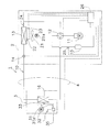
- the perspective view which shows the external appearance of the air conditioner which concerns on embodiment.
- a circuit diagram showing an outline of composition of an air harmony machine concerning an embodiment.
- the block diagram which shows schematic structure of the control system of an air conditioner.
- the ph diagram for demonstrating the concept of the refrigerating cycle of the air conditioner which concerns on embodiment.
- the perspective view of a four-way selector valve Typical sectional drawing for demonstrating the state of the four-way selector valve during a defrost operation. Typical sectional drawing for demonstrating the state of the four-way selector valve during heating operation.
- Timing chart regarding operating frequency of compressor (b) Timing chart regarding defrost request flag, (c) Timing chart regarding residual operation command, (d) Timing chart regarding upper limit of indoor fan, (e) Four-way switching The timing chart regarding the switching of a valve, (f) The timing chart regarding ON / OFF of an outdoor fan, (g) The timing chart regarding the opening degree of an expansion mechanism.
- FIGS. 1 and 2 An outline of the configuration of the air conditioner according to this embodiment is shown in FIGS. 1 and 2.
- An air conditioner 1 shown in FIG. 1 includes an indoor unit 3 attached to an indoor wall surface WL and the like, and an outdoor unit 2 installed outdoors.
- the outdoor unit 2 is indicated by a broken line because the outdoor unit 2 is outside the indoor unit 3 with the wall surface WL interposed therebetween.
- FIG. 2 shows a circuit configuration of the air conditioner 1.
- the air conditioner 1 includes a refrigerant circuit 10 and can perform a vapor compression refrigeration cycle by circulating the refrigerant in the refrigerant circuit 10.
- the indoor unit 3 and the outdoor unit 2 are connected by a communication pipe 4.
- the air conditioner 1 is provided with the control part 50 in order to control an internal apparatus.
- a remote controller 5 is attached to the air conditioner 1, and the remote controller 5 has a function of communicating with the control unit 50 using, for example, infrared rays. Therefore, the user can make various settings for the air conditioner 1 using the remote controller 5.
- the refrigerant circuit 10 includes a compressor 11, a four-way switching valve 12, an outdoor heat exchanger 13, an expansion mechanism 14, an accumulator 15, and an indoor heat exchanger 16.
- the compressor 11 discharges the refrigerant compressed by sucking the refrigerant from the suction port to the first port of the four-way switching valve 12 from the discharge port.
- the four-way switching valve 12 further has a second port connected to the outdoor heat exchanger 13, a third port connected to the accumulator 15, and a fourth port connected to the indoor heat exchanger 16.
- the four-way switching valve 12 causes the refrigerant to flow between the first port and the fourth port as shown by the broken line when the air conditioner 1 performs the heating operation, and at the same time the second port and the second port. A refrigerant is circulated between the three ports. Further, when the air conditioner 1 performs the cooling operation and the reverse cycle defrost operation, the four-way switching valve 12 circulates the refrigerant between the first port and the second port, as indicated by the solid line. At the same time, the refrigerant is circulated between the third port and the fourth port.
- the outdoor heat exchanger 13 has a gas side inlet / outlet for mainly allowing the gas refrigerant to flow between the second port of the four-way switching valve 12 and allows the liquid refrigerant to mainly flow between the expansion mechanism 14. For the liquid side.
- the outdoor heat exchanger 13 exchanges heat between the refrigerant flowing through a heat transfer tube (not shown) connected between the liquid side inlet and outlet and the gas side inlet and outlet of the outdoor heat exchanger 13 and the outdoor air.
- the expansion mechanism 14 is disposed between the outdoor heat exchanger 13 and the indoor heat exchanger 16.
- the expansion mechanism 14 has a function of expanding and depressurizing the refrigerant flowing between the outdoor heat exchanger 13 and the indoor heat exchanger 16.
- the indoor heat exchanger 16 has a liquid side inlet / outlet for flowing the liquid refrigerant to / from the expansion mechanism 14 and a gas side for flowing the gas refrigerant to / from the fourth port of the four-way switching valve 12. Has a doorway.
- the indoor heat exchanger 16 exchanges heat between refrigerant flowing through a heat transfer tube (not shown) connected between the liquid side inlet and outlet and the gas side inlet and outlet of the indoor heat exchanger 16 and the room air.
- An accumulator 15 is disposed between the third port of the four-way switching valve 12 and the suction port of the compressor 11.
- the refrigerant flowing from the third port of the four-way switching valve 12 to the compressor 11 is separated into gas refrigerant and liquid refrigerant.
- a gas refrigerant is mainly supplied from the accumulator 15 to the suction port of the compressor 11.
- the outdoor unit 2 includes an outdoor fan 21 that generates an air flow of outdoor air passing through the outdoor heat exchanger 13 in order to promote heat exchange between the refrigerant flowing through the heat transfer tube and the outdoor air.
- the outdoor fan 21 is driven by an outdoor fan motor 21a that can change the rotational speed.
- the indoor unit 3 also includes an indoor fan 31 that generates an air flow of indoor air that passes through the indoor heat exchanger 16 in order to promote heat exchange between the refrigerant flowing through the heat transfer tubes and the room air.
- the indoor fan 31 is driven by an indoor fan motor 31a whose rotation speed can be changed.
- the indoor unit 3 is provided with a wind direction adjusting blade 36.
- the indoor unit 3 shown in FIG. 1 is in a state where the air outlet is closed by the wind direction adjusting blade 36.
- the wind direction adjusting blade 36 is driven by a wind direction adjusting blade drive motor 37 (see FIG. 3), and hot air is blown out from the open outlet.
- the indoor air sucked into the indoor unit 3 is sucked from a suction port (not shown) above the indoor unit 3.
- control unit 50 is built in the outdoor control device 26 built in the outdoor unit 2 and the indoor unit 3.
- the indoor control device 35 is provided.
- the outdoor control device 26 and the indoor control device 35 are connected to each other through signal lines, and are configured to be able to transmit and receive signals to each other.
- the outdoor control device 26 of the outdoor unit 2 controls the compressor 11, the four-way switching valve 12, the expansion mechanism 14, the outdoor fan 21, and the like. Therefore, the outdoor unit 2 includes an outdoor temperature sensor 22 for measuring the temperature of the outdoor air, an outdoor heat exchanger temperature sensor 23 for measuring the temperature of the refrigerant flowing in a specific place of the outdoor heat exchanger 13, and The outlet pipe temperature sensor 24 for detecting the temperature of the refrigerant flowing out from the gas side inlet / outlet of the outdoor heat exchanger 13 functioning as an evaporator during the heating operation, and the temperature of the gas refrigerant sucked into the compressor 11 And a suction pipe temperature sensor 25 for detection.
- the outdoor control device 26 is connected to the outdoor temperature sensor 22 and the outdoor heat exchanger temperature sensor 23 in order to receive signals related to the temperatures measured by the outdoor temperature sensor 22 and the outdoor heat exchanger temperature sensor 23.
- the outdoor control device 26 includes, for example, a CPU (not shown) and a memory (not shown), and is configured to be able to control the outdoor unit 2 according to a stored program or the like.
- the indoor control device 35 of the indoor unit 3 controls the indoor fan 31 and the like. Therefore, the indoor unit 3 includes an indoor temperature sensor 32 for measuring the temperature of the indoor air, an indoor heat exchanger temperature sensor 33 for measuring the temperature of the refrigerant flowing in a specific place of the indoor heat exchanger 16, and It has. And the indoor control apparatus 35 is connected to the indoor temperature sensor 32 and the indoor heat exchanger temperature sensor 33 in order to receive the signal regarding the temperature which the indoor temperature sensor 32 and the indoor heat exchanger temperature sensor 33 measured.
- the indoor control device 35 includes, for example, a CPU (not shown) and a memory (not shown), and is configured to be able to control the outdoor unit 2 according to a stored program or the like.
- the remote controller 5 has a liquid crystal display device 5a and a button 5b shown in FIG.
- the remote controller 5 is provided with an operation switch 51, an operation changeover switch 52, a temperature setting switch 53, and an air volume setting switch 54, and the user can operate these switches using the button 5b.
- the operation switch 51 is a switch for switching between the operation and the stop of the air conditioner 1, and the operation and the stop are alternately switched every time the operation switch 51 is operated.
- the operation changeover switch 52 is used, for example, when selecting a cooling operation or a heating operation.
- the temperature setting switch 53 is a switch used to input a room temperature desired by the user.
- the air volume setting switch 54 is a switch used to input an air volume desired by the user.
- the controller 50 sets the target indoor temperature Tt based on the set temperature Ts input using the temperature setting switch 53. For example, (Ts + ⁇ 1) obtained by adding a constant value ⁇ 1 to the set temperature Ts is set as the target indoor temperature Tt.
- the control unit 50 causes the air conditioner 1 to be thermo-off. Note that the control unit 50 causes the air conditioner 1 to be thermo-ON if the room temperature Tr becomes lower than a value obtained by subtracting the constant value ⁇ 2 from the set temperature Ts (Ts ⁇ 2).
- the control unit 50 controls various devices constituting the air conditioner 1 based on the measurement values of the various sensors as described above and the commands input from the remote controller 5. Further, the control unit 50 notifies the user of the state of the input command and the state of control using the liquid crystal display device 5a of the remote controller 5.
- the low-temperature and high-pressure refrigerant deprived of the temperature by the indoor heat exchanger 16 is decompressed by the expansion mechanism 14 to be changed to a low-temperature and low-pressure refrigerant.
- the refrigerant that has flowed into the outdoor heat exchanger 13 via the expansion mechanism 14 is warmed by heat exchange with the outdoor air, evaporates, and changes from liquid refrigerant to gas refrigerant.
- the outdoor heat exchanger 13 functions as an evaporator.
- refrigerant composed mainly of low-temperature gas refrigerant is sucked into the compressor 11 from the outdoor heat exchanger 13 through the four-way switching valve 12 and the accumulator 15.
- FIG. 4 shows the concept of a Mollier diagram (ph diagram) during heating operation.
- the air conditioner 1 is configured such that the refrigerant circulates by repeatedly repeating four state changes of evaporation, compression, condensation, and expansion.
- the high pressure value P1 of the refrigerant circuit 10 shown in FIG. 4 is the condensation pressure of the outdoor heat exchanger 13, and the low pressure value P2 of the refrigerant circuit 10 is the evaporation pressure of the indoor heat exchanger 16.
- This high pressure value P1 (condensation pressure) is substantially the same as the discharge pressure of the compressor 11.
- the low-temperature and high-pressure refrigerant whose temperature has been deprived by the outdoor heat exchanger 13 is reduced in pressure by the expansion mechanism 14 and changed to a low-temperature and low-pressure refrigerant.
- the refrigerant that has flowed into the indoor heat exchanger 16 through the expansion mechanism 14 cools the indoor air by heat exchange with the indoor air, is warmed, and evaporates to change from a liquid refrigerant to a gas refrigerant.
- the indoor heat exchanger 16 functions as an evaporator.
- the refrigerant mainly composed of low-temperature gas refrigerant is sucked into the compressor 11 from the indoor heat exchanger 16 through the four-way switching valve 12 and the accumulator 15.
- the reverse cycle defrost operation is performed to remove frost attached to the outdoor heat exchanger 13 due to the heating operation. Accordingly, the operation is switched to the reverse cycle defrost operation in the middle of the heating operation, and when the reverse cycle defrost operation is completed, the operation returns to the heating operation again.
- the reverse cycle defrost operation as in the cooling operation, the four-way switching valve 12 is switched to the solid line state shown in FIG. In the reverse cycle defrost operation, the same vapor compression refrigeration cycle as in the cooling operation is repeated.
- the reverse cycle defrost operation is performed in the reverse cycle of the heating operation, and the vapor compression is performed by flowing the refrigerant in the order of the compressor 11, the outdoor heat exchanger 13, the expansion mechanism 14, and the indoor heat exchanger 16. It is the reverse cycle which repeats a formula refrigeration cycle.
- the high pressure value P3 of the refrigerant circuit 10 shown by the broken line in FIG. 4 is the condensation pressure of the outdoor heat exchanger 13 that functions as a condenser.
- the portions other than the high pressure value P3 of the refrigerant circuit 10 during the reverse cycle defrost operation are omitted, but the refrigerant evaporates, compresses, condenses, and expands during the reverse cycle defrost operation as in the heating operation. Cycle through one state change in sequence.
- the high pressure value P3 (condensation pressure) is substantially the same as the discharge pressure of the compressor 11. As shown in FIG. 4, the high pressure value P3 of the refrigerant circuit 10 during the reverse cycle defrost operation is set to be lower than the high pressure value P1 of the refrigerant circuit 10 during the heating operation.
- the outdoor control device 26 of the outdoor unit 2 When entering the reverse cycle defrost operation, it is determined that the outdoor control device 26 of the outdoor unit 2 performs defrosting when the heating control is being performed. When it is determined that the outdoor unit 2 performs defrosting, the defrosting request flag shown in FIG. 8B is changed from “0” to “1”, and the outdoor control device 26 of the outdoor unit 2 changes to the indoor unit. The defrost request signal is transmitted to the three indoor control devices 35.
- the indoor control device 35 transmits a defrost permission signal to the outdoor control device 26.
- the outdoor control device 26 receives the defrost permission signal, the outdoor control device 26 starts the defrost control and transmits a signal indicating that defrosting is being performed to the indoor control device 35.
- the outdoor control device 26 determines that the defrosting is finished in the outdoor unit 2
- the defrost request flag in FIG. 8B changes from “1” to “0”
- the outdoor control device 26 changes to the indoor unit 3.
- a normal notification signal for notifying that the indoor control device 35 is returned to the normal heating operation is transmitted.
- the indoor unit 3 that has received the normal notification signal returns to the heating control for the heating operation.
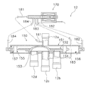
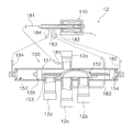
- FIG. 5 is a perspective view of the four-way switching valve 12.
- 6 and 7 are schematic cross-sectional views for explaining the configuration of the four-way switching valve 12. 5, 6, and 7, the four-way switching valve 12 includes a main body mechanism 150 and a pilot mechanism 170.
- the main body mechanism 150 includes a cylinder 151, a slide base 153, and a slide valve 152 (see FIG. 6).
- the slide table 153 is a table arranged at the center part in the cylinder 151.
- a third port 12c is disposed at the center of the slide table 153, and a second port 12b and a fourth port 12d are provided on both sides thereof along the axial direction of the cylinder.
- a first port 12 a is provided at a position facing the third port 12 c of the slide base 153.
- the state shown in FIG. 6 is a state during the reverse cycle defrost operation or the cooling operation, and is in the connection state shown by the solid line in FIG.
- the state shown in FIG. 7 is a state during heating operation, and is in a connected state shown by a broken line in FIG.
- a slide valve 152 is arranged in the cylinder 151, It is configured to be slidable in the axial direction.
- the slide valve 152 slides on the slide table 153. Further, the center portion of the slide valve 152 is processed into an inverted U shape.
- the slide valve 152 is connected by the inverted U-shaped portion so that the refrigerant can flow between the adjacent ports.
- partition members 154 and 155 on both sides of the slide valve 152, a first chamber 156 is formed between the partition member 154 and the cylinder 151, and a second chamber 157 is formed between the partition member 155 and the cylinder 151. Is formed.
- the slide valve 152 is driven by the pressure difference between the first chamber 156 and the second chamber 157.
- the main body mechanism 150 and the pilot mechanism 170 are connected by four first pilot pipes 181, second pilot pipes 182, third pilot pipes 183, and fourth pilot pipes 184.
- the first pilot pipe 181 is connected to the first port 12a.
- the third pilot pipe 183 is connected to the third port 12c.
- the second pilot pipe 182 is connected to the first chamber 156, and the fourth pilot pipe 184 is connected to the second chamber 157.
- the pilot mechanism 170 switches the connection from the first pilot pipe 181 to the third pilot pipe 183 using a built-in spring and electromagnet.
- the first chamber 156 of the cylinder 151 of the main body mechanism 150 has a low pressure and the second chamber 157 has a high pressure as shown in FIG. 6 (hereinafter referred to as a left side position state), or the first chamber.
- the state shown in FIG. 7 (hereinafter referred to as the right-side position state) is switched to make 156 a high pressure and make the second chamber 157 a low pressure.
- the four-way switching valve 12 is switched without the pressure difference between the first port 12a and the second port 12b being eliminated, the first port 12a suddenly changes to the second port 12b, which was at a low pressure until just before. Since the high pressure from acts, an impact sound is generated by the impact at that time. In the air conditioner 1, as will be described later, when returning from the reverse cycle defrost operation to the heating operation, the pressure difference is eliminated as much as possible to reduce the impact sound as much as possible.
- FIGS. 8 (a) to 8 (g) Start of reverse cycle defrost operation
- the operation of the air conditioner 1 during reverse cycle defrost operation is shown in FIGS. 8 (a) to 8 (g).
- the timing chart will be described.
- the defrost request flag changes from “0” to “1” at time t1, and the outdoor of the control unit 50 is detected at this timing.
- a defrost request signal is transmitted from the control device 26 to the indoor control device 35.
- the upper limit of the rotation speed of the indoor fan 31 is less than the limit during normal heating operation.
- the compressor 11 reaches a predetermined operating frequency Fmin at time t2.
- the operating frequency decreasing speed (normal frequency decreasing speed) when reaching from time t1 to time t2 is, for example, 2 Hz / second.
- the increase rate of the operation frequency during the heating operation is also set to 2 Hz / second.
- the four-way switching valve 12 is switched from the heating side to the cooling side.
- the connection state of the four-way switching valve 12 in which the four-way switching valve 12 is shown in FIG. 5 is switched from the broken line connection state in FIG. 2 to the solid line connection state.
- the compressor 11 thereafter starts to increase the rotational speed (time t5 in FIG. 8A).
- the operating frequency of the compressor 11 (see FIG. 8A) and the opening of the expansion mechanism 14 (see FIG. 8B) are: It is controlled by the outdoor control device 26 according to the sequence stored in the memory.
- the outdoor control device 26 performs a defrosting completion determination for ending the defrosting operation.
- the residual operation command is changed from “0” to “0” at time t6 as shown in FIG. 1 "and a command to perform the residual operation is issued.
- the operating frequency of the compressor 11 is gradually lowered to the residual operating frequency Fmin (time t7), and this residual operating frequency Fmin is held for a predetermined time (t8-t7).
- time t6 when the residual operation command is issued, as shown in FIG. 4, the high pressure value P3 of the refrigerant circuit 10 is lower than the high pressure value P1 of the refrigerant circuit 10 during the heating operation. Therefore, the speed of decrease in the operating frequency of the compressor 11 (frequency reduction speed at the end of defrosting) is set to 10 Hz / second, for example.
- the rotational frequency of the compressor 11 that has been operated at several tens Hz is reduced to several tens of Hz (residual operating frequency Fmin) in a few seconds.
- the frequency reduction speed at the end of defrosting is set to 5 times the normal frequency reduction speed, but an improvement in heating capacity can be expected even if it is set to, for example, twice or more.
- the heating operation is interrupted. Therefore, as the value of heating operation time ⁇ (heating operation time + defrosting operation time) is larger, it becomes easier to obtain a high heating capacity, particularly a high low temperature heating capacity. Further, by switching from the reverse cycle defrost operation to the heating operation while maintaining the residual operation frequency Fmin without stopping the compressor 11, it becomes easy to obtain a higher low-temperature heating capacity.
- the pressure difference between the first port 12a and the third port 12c of the four-way switching valve 12 can be reduced.
- the impact sound of the four-way switching valve 12 is significantly suppressed by performing the residual operation as compared with the case where the residual operation is not performed.
- the four-way switching valve 12 is discharged from the solid line connection to the broken line connection, that is, from the compressor 11, as shown in FIG. 8 (e).
- the refrigerant is sent to the indoor heat exchanger 16, and the refrigerant flowing out of the outdoor heat exchanger 13 is switched to a path for sucking into the compressor 11 (time t8).
- the outdoor control device 26 of the control unit 50 changes the residual operation command from “1” to “0” and starts to increase the operating frequency of the compressor 11.
- the indoor control device 35 changes the upper limit of the rotation speed of the indoor fan 31 from time t8 to the normal limit from the defrosting limit.
- the four-way switching valve 12 has been described as the switching mechanism, but the switching mechanism is not limited to the four-way switching valve 12. Used for switching between heating operation and defrosting operation, in order to suppress noise during switching between these operations, a port connected to the discharge port of the compressor 11 and a port connected to the suction port of the compressor Any switching mechanism that requires pressure equalization may be used other than the four-way switching valve.
- the compressor 11 is in the defrosting operation from time t6 to time t7 shown in FIG.
- the defrosting end frequency reduction rate becomes faster than, for example, the normal frequency reduction rate from time t1 to time t2.
- the time from the time t6 to the time t7 can be shortened, and when the defrosting operation is completed, the operating frequency at which the pressure equalization of the four-way switching valve 12 that is the switching mechanism can be quickly reached can be achieved.
- the time until the four-way switching valve 12 is switched can be shortened.
- the frequency reduction speed at the end of defrosting is 10 Hz / second and is set to a speed that is twice or more the normal frequency reduction speed of 2 Hz / second. Greater time reduction effect.
- the reduction speed is preferably as short as possible within a range that does not adversely affect the compressor 11, and should be 5 times or more (frequency reduction speed at the end of defrosting / normal frequency reduction speed) as in the above-described embodiment. Further preferred.
- the operation when the operating frequency of the compressor 11 is decreased from time t6 at the normal frequency reduction speed instead of the frequency reduction speed at the time of defrosting is indicated by a broken line.
- the time from the time t8 to the time t9 is shortened compared to the conventional case.
- the value of ⁇ heating operation time / (heating operation time + defrosting operation time) ⁇ related to the heating capacity of the above embodiment is shortened by the amount of time from time t8 to time t9. It can be seen that the heating capacity is easily improved.
- the air conditioner 1 described above does not stop and the compressor 11 does not stop when returning from the defrosting operation to the heating operation (between time t6 and time t8).
- Maintaining the frequency Fmin (an example of maintaining an operating frequency equal to or higher than a predetermined value) means that the compressor 11 is driven at an operating frequency equal to or higher than a predetermined value when returning to the heating operation.
- the compressor can be raised to the required operating frequency in a short time compared to the conventional case where the compressor 11 is stopped when the heating operation is restored, and it becomes easy to ensure the low-temperature heating capacity.
- Air conditioner (example of refrigeration equipment) 2 outdoor unit 3 indoor unit 10 refrigerant circuit 11 compressor 12 four-way switching valve (example of switching mechanism) 13 Outdoor heat exchanger (example of evaporator during heating operation) 14 Expansion mechanism 16 Indoor heat exchanger (example of condenser during heating operation) 21 outdoor fan 22 outdoor temperature sensor 23 outdoor heat exchanger temperature sensor 24 outdoor control device 31 indoor fan 32 indoor temperature sensor 33 indoor heat exchanger temperature sensor 34 indoor control device 50 controller
Landscapes
- Engineering & Computer Science (AREA)
- Mechanical Engineering (AREA)
- General Engineering & Computer Science (AREA)
- Physics & Mathematics (AREA)
- Thermal Sciences (AREA)
- Chemical & Material Sciences (AREA)
- Combustion & Propulsion (AREA)
- Air Conditioning Control Device (AREA)
- Air-Conditioning For Vehicles (AREA)
Abstract
Description
以下、本発明の一実施形態に係る冷凍装置として空気調和機を例に挙げて説明する。この一実施形態に係る空気調和機の構成の概要が図1及び図2に示されている。図1に示されている空気調和機1は、室内の壁面WLなどに取り付けられる室内機3と、屋外に設置される室外機2とを備えている。なお、図1においては、室外機2が壁面WLを挟んで室内機3とは反対側の屋外にあることから、室外機2が破線で示されている。図2には、空気調和機1の回路構成が示されている。この空気調和機1は、冷媒回路10を備えており、冷媒回路10の中の冷媒を循環させることにより蒸気圧縮式冷凍サイクルを実行することができる。冷媒が循環する冷媒回路10を形成するために、連絡配管4によって、室内機3と室外機2が接続されている。また、空気調和機1は、内部の機器を制御するために制御部50を備えている。空気調和機1には、リモートコントローラ5が付属しており、このリモートコントローラ5は、例えば赤外線を用いて制御部50と通信する機能を持っている。従って、ユーザは、リモートコントローラ5を用いて空気調和機1に対して種々の設定を行うことができる。 (1) Outline of Configuration of Air Conditioner Hereinafter, an air conditioner will be described as an example of a refrigeration apparatus according to an embodiment of the present invention. An outline of the configuration of the air conditioner according to this embodiment is shown in FIGS. 1 and 2. An
冷媒回路10は、圧縮機11と、四路切換弁12と、室外熱交換器13と、膨張機構14と、アキュムレータ15と、室内熱交換器16とを備えている。吸入口から冷媒を吸入して圧縮した冷媒を、圧縮機11は、吐出口から四路切換弁12の第1ポートに対して吐出する。四路切換弁12は、さらに、室外熱交換器13に接続された第2ポートと、アキュムレータ15に接続された第3ポートと、室内熱交換器16に接続された第4ポートとを有する。 (1-1) Refrigerant
The
図3に示されているように、制御部50は、室外機2内に内蔵されている室外制御装置26と室内機3内に内蔵されている室内制御装置35とを有している。これら室外制御装置26と室内制御装置35とは、相互に信号線で接続され、互いに信号を送受信できるように構成されている。 (1-2) Configuration Overview of Control System of
(2-1)暖房運転
空気調和機1の暖房運転のときは、四路切換弁12は、図2に示された破線の状態に切り換わる。すなわち、圧縮機11から吐出された高温高圧のガス冷媒は、四路切換弁12を介して室内熱交換器16に流れ込む。このとき、室内熱交換器16は、凝縮器として機能する。そのため、室内熱交換器16の中を流れるに従って、冷媒は、室内空気との熱交換によって室内空気を暖めて自身が冷やされ、凝縮してガス冷媒から液冷媒に変化する。室内熱交換器16で温度を奪われた低温高圧の冷媒は、膨張機構14によって減圧されて低温低圧の冷媒に変化する。膨張機構14を経て室外熱交換器13に流れ込んだ冷媒は、室外空気との熱交換によって暖められ、蒸発して液冷媒からガス冷媒に変化する。このとき、室外熱交換器13は、蒸発器として機能している。そして、室外熱交換器13から四路切換弁12及びアキュムレータ15を介して、主に低温のガス冷媒からなる冷媒が圧縮機11に吸入される。このような圧縮機11、室内熱交換器16、膨張機構14及び室外熱交換器13の順に冷媒を流して、このような蒸気圧縮式冷凍サイクルを繰り返すのが正サイクルである。図4には、暖房運転時のモリエル線図(p-h線図)の概念が示されている。図4に示されているように、空気調和機1では、冷媒が蒸発、圧縮、凝縮、膨張の4つの状態変化を順に繰り返して循環するように構成されている。図4に示されている冷媒回路10の高圧値P1は室外熱交換器13の凝縮圧力であり、冷媒回路10の低圧値P2は室内熱交換器16の蒸発圧力である。この高圧値P1(凝縮圧力)は、圧縮機11の吐出圧力と実質的に同じである。 (2) Overview of heating operation, cooling operation and reverse cycle defrost operation (2-1) Heating operation During the heating operation of the
空気調和機1の冷房運転のときは、四路切換弁12は、図2に示された実線の状態に切り換わる。すなわち、圧縮機11から吐出された高温高圧のガス冷媒は、四路切換弁12を介して室外熱交換器13に流れ込む。このとき、室外熱交換器13は、凝縮器として機能する。そのため、室外熱交換器13の中を流れるに従って、冷媒は、室外空気との熱交換によって冷やされ、凝縮してガス冷媒から液冷媒に変化する。室外熱交換器13で温度を奪われた低温高圧の冷媒は、膨張機構14によって減圧されて低温低圧の冷媒に変化する。膨張機構14を経て室内熱交換器16に流れ込んだ冷媒は、室内空気との熱交換によって室内空気を冷やして自身が暖められ、蒸発して液冷媒からガス冷媒に変化する。このとき、室内熱交換器16は、蒸発器として機能している。そして、室内熱交換器16から四路切換弁12及びアキュムレータ15を介して、主に低温のガス冷媒からなる冷媒が圧縮機11に吸入される。 (2-2) Cooling Operation When the
逆サイクルデフロスト運転は、暖房運転が行なわれたことで室外熱交換器13に付着した霜を取るために行われる。従って、暖房運転の途中で逆サイクルデフロスト運転に切り換わり、逆サイクルデフロスト運転が終了すると再び暖房運転に復帰する。逆サイクルデフロスト運転では、冷房運転と同じように、四路切換弁12が、図2に示された実線の状態に切り換わる。そして、逆サイクルデフロスト運転でも、冷房運転と同様の蒸気圧縮式冷凍サイクルが繰り返される。つまり、暖房運転時の正サイクルとは逆に、逆サイクルデフロスト運転で行なわれるのは、圧縮機11、室外熱交換器13、膨張機構14及び室内熱交換器16の順に冷媒を流して蒸気圧縮式冷凍サイクルを繰り返す逆サイクルである。逆サイクルデフロスト運転では、図4に破線で示されている冷媒回路10の高圧値P3は、凝縮器として機能する室外熱交換器13の凝縮圧力である。図4において逆サイクルデフロスト運転時の冷媒回路10の高圧値P3以外の部分は省略されているが、暖房運転と同様に、逆サイクルデフロスト運転時においても冷媒が蒸発、圧縮、凝縮、膨張の4つの状態変化を順に繰り返して循環する。この高圧値P3(凝縮圧力)は、実質的に圧縮機11の吐出圧力と同じである。図4に示されているように、暖房運転時の冷媒回路10の高圧値P1に比べて逆サイクルデフロスト運転時の冷媒回路10の高圧値P3が低くなるように設定されている。 (2-3) Reverse cycle defrost operation The reverse cycle defrost operation is performed to remove frost attached to the
(3-1)四路切換弁12の構成
図5は、四路切換弁12の斜視図である。また、図6及び図7は、四路切換弁12の構成を説明するための模式的な断面図である。図5、図6及び図7において、四路切換弁12は、本体機構150とパイロット機構170とを備えている。本体機構150は、シリンダ151と、スライド台153と、スライド弁152とを有している(図6参照)。 (3) Impact Sound at Four-way Switching Valve Operation (3-1) Configuration of Four-
上記構成の四路切換弁12において、左側位置状態では、シリンダ151内のスライド弁152が図6に示されているように左側に位置し、第1ポート12aと第2ポート12bとが連通し、第4ポート12dと第3ポート12cとが連通している。左側位置状態では、第1パイロット管181と第2パイロット管182が接続され、第3パイロット管183と第4パイロット管184が接続されている。この左側位置状態で、パイロット機構170の電磁石が励磁されると第1パイロット管181と第4パイロット管184が接続されるとともに第2パイロット管182と第3パイロット管183が接続されて、シリンダ151の両端の圧力差はスライド弁152が右側に移動するような圧力差となる。スライド弁152が右側に移動して右側位置状態になると、第1ポート12aと第4ポート12dとが連通し、第3ポート12cと第2ポート12bとが連通する。 (3-2) Operation of Four-
例えば暖房運転中は、パイロット機構170の電磁石が非励磁であるので、スライド弁152は図7に示されている右側位置状態にあり、第1ポート12aと第4ポート12dとが連通し、第2ポート12bと第3ポート12cとが連通している。このとき、逆サイクルデフロスト運転への移行指令が入ると、シリンダ151の両端の圧力差はスライド弁152が左側に移動するような圧力差となり、スライド弁152が左側に移動する。その結果、第1ポート12aと第2ポート12bとが連通し、第3ポート12cと第4ポート12dとが連通する。もし、第1ポート12aと第2ポート12bの圧力差が解消されないままで四路切換弁12の切り換えが行われてしまうと、直前まで低圧であった第2ポート12bに、いきなり第1ポート12aからの高圧が作用するので、そのときの衝撃によって衝撃音が発生することになる。空気調和機1では、後ほど説明するが、逆サイクルデフロスト運転から暖房運転に復帰する際には、この圧力差をできるだけ解消して衝撃音をできる限り小さくすることが行われている。 (3-3) Impact Sound Generation Mechanism During the heating operation, for example, since the electromagnet of the
(4-1)逆サイクルデフロスト運転の開始
逆サイクルデフロスト運転時の空気調和機1の動作について、図8(a)~図8(g)に示されているタイミングチャートを用いて説明する。図8(b)に示されている除霜要求フラグのタイミングチャートを見ると、時刻t1において除霜要求フラグが「0」から「1」に変化しており、このタイミングで制御部50の室外制御装置26から室内制御装置35に除霜要求信号が送信される。また時刻t1には、図8(d)に示されているように、除霜要求信号を受信した室内機3では、室内ファン31の回転数の上限制限が、通常の暖房運転時の制限から除霜用の制限に切り換えられる。通常の暖房運転では、例えば、風量設定スイッチ54で入力可能な最大風量に対応して室内ファン31の回転数の上限制限が設けられている。それに対して、除霜用の制限が室内ファン31に課されているときには、風量設定スイッチ54で最大風量に設定されていても、制御部50は、室内ファン31の回転数を最大風量時の回転数よりも小さな回転数に制限する。このような除霜用の制限が室内ファン31の回転数に設けられることにより、除霜運転時に吹出される冷風によってユーザが感じる不快感が抑制される。そして、室外機2では、室外制御装置26により、時刻t1から圧縮機11の運転周波数を徐々に下げる制御が開始される。 (4) Operation during reverse cycle defrost operation (4-1) Start of reverse cycle defrost operation The operation of the
逆サイクルデフロスト運転中は、圧縮機11の運転周波数(図8(a)参照)及び膨張機構14の開度(図8(b)参照)が、メモリに記憶されているシーケンスに従って室外制御装置26により制御される。室外制御装置26は、除霜運転を終了するための除霜完了判定が行なわれる。除霜運転を終了するための除霜完了判定で、除霜運転を完了する判定がでると、図8(c)に示されているように、時刻t6において残留運転指令が「0」から「1」に変化し、残留運転を行なう指令が出される。残留運転指令が出されると、圧縮機11の運転周波数を徐々に下げていって残留運転周波数Fminまで下げ(時刻t7)、この残留運転周波数Fminを所定時間(t8-t7)だけ保持する。残留運転指令が出される時刻t6においては、図4に示されているように、冷媒回路10の高圧値P3は、暖房運転時の冷媒回路10の高圧値P1よりも低くなっている。そのため、圧縮機11の運転周波数の減少速度(除霜終了時周波数減少速度)は、例えば、10Hz/秒に設定されている。例えば、数十Hzで運転されていた圧縮機11の回転周波数を、数秒で十数Hz(残留運転周波数Fmin)まで低下させる。ここでは、除霜終了時周波数減少速度が通常周波数減少速度の5倍に設定されているが、例えば2倍以上に設定されていても暖房能力の向上は見込める。逆サイクルデフロスト運転(除霜運転)の間は、暖房運転が中断される。従って、暖房運転時間÷(暖房運転時間+除霜運転時間)の値が大きい程、高い暖房能力、特に高い低温暖房能力を得ることが容易になる。また、圧縮機11を停止せずに残留運転周波数Fminを維持した状態で、逆サイクルデフロスト運転から暖房運転に切り換えることによって、さらに高い低温暖房能力を得ることが容易になる。 (4-2) Control during reverse cycle defrost operation During the reverse cycle defrost operation, the operating frequency of the compressor 11 (see FIG. 8A) and the opening of the expansion mechanism 14 (see FIG. 8B) are: It is controlled by the
(5-1)変形例A
上記実施形態では、切換機構として四路切換弁12について説明したが、切換機構は四路切換弁12に限られるものではない。暖房運転と除霜運転の切換に用いられ、これらの運転の切換時の騒音を抑制するために圧縮機11の吐出口に接続されているポートと圧縮機の吸入口に接続されているポートの均圧を要する切換機構であれば、四路切換弁以外のものであってもよい。 (5) Modification (5-1) Modification A
In the above embodiment, the four-
上記実施形態では、図8(a)の時刻t7から時刻t8までの残留運転周波数が一定である場合について説明したが、均圧を行える範囲であればこの間の残留運転周波数を変化させてもよい。 (5-2) Modification B
In the above embodiment, the case where the residual operating frequency from time t7 to time t8 in FIG. 8A is constant has been described. However, the residual operating frequency may be changed as long as pressure equalization is possible. .
(6-1)
以上説明したように、本発明の一実施形態に係る冷凍装置である空気調和機1においては、圧縮機11は、図8(a)に示されている時刻t6から時刻t7における除霜運転中の除霜終了時周波数減少速度が、例えば時刻t1から時刻t2までの通常周波数減少速度よりも速くなる。その結果、時刻t6から時刻t7までの時間を短縮して、除霜運転を終了するときに切換機構である四路切換弁12の均圧が可能な運転周波数に速く到達させることができるので、四路切換弁12を切り換えるまでの時間を短縮することができる。例えば、時刻t6から通常周波数減少速度で運転周波数を減少させた場合、図8(a)の時刻t9まで掛かり、除霜運転時間が長くなる。同じ残留運転周波数Fminに到達するまでの時間が短縮されることで、除霜運転時間を短縮して、暖房運転の復帰時に発生する騒音の抑制とともに暖房能力を確保することが容易になる。 (6) Features (6-1)
As described above, in the
上述の空気調和機1では、除霜終了時周波数減少速度が10Hz/秒であって2Hz/秒の通常周波数減少速度の2倍以上の減少速度に設定されていることから、除霜運転時間の時間短縮効果が大きくなる。勿論、減少速度は、圧縮機11に悪影響を及ぼさない範囲でできるだけ短い方が好ましく、上述の実施形態のように5倍以上(除霜終了時周波数減少速度/通常周波数減少速度)であることがさらに好ましい。 (6-2)
In the
上述の空気調和機1は、図8(a)に示されているように、除霜運転から暖房運転に復帰するとき(時刻t6から時刻t8の間)、圧縮機11が止まらずに残留運転周波数Fminを維持する(所定値以上の運転周波数を保つ例)ということは、暖房運転に復帰したときに圧縮機11が所定値以上の運転周波数で駆動されているということである。その結果、暖房運転復帰時に例えば圧縮機11が停止していた従来の場合に比べて、圧縮機を必要な運転周波数に短い時間で上昇させることができ、低温暖房能力を確保し易くなる。 (6-3)
As shown in FIG. 8 (a), the
除霜終了時周波数減少速度で変化した後に、図8(a)の時刻t7から時刻t8までの期間のように暖房運転に入るまでに所定時間にわたって一定の運転周波数を維持することで、切換機構である四路切換弁12の均圧を十分に行うことができる。その結果、暖房運転への復帰時に圧縮機11が停止せずに残留運転周波数Fminで駆動されていても、四路切換弁12で発生する騒音を抑制することができる。 (6-4)
After changing at the frequency reduction speed at the time of defrosting completion, the switching mechanism is maintained by maintaining a constant operating frequency for a predetermined time until the heating operation is started as in the period from time t7 to time t8 in FIG. The pressure equalization of the four-
2 室外機
3 室内機
10 冷媒回路
11 圧縮機
12 四路切換弁(切換機構の例)
13 室外熱交換器(暖房運転時の蒸発器の例)
14 膨張機構
16 室内熱交換器(暖房運転時の凝縮器の例)
21 室外ファン
22 室外温度センサ
23 室外熱交換器温度センサ
24 室外制御装置
31 室内ファン
32 室内温度センサ
33 室内熱交換器温度センサ
34 室内制御装置
50 制御部 1 Air conditioner (example of refrigeration equipment)
2
13 Outdoor heat exchanger (example of evaporator during heating operation)
14
21
Claims (4)
- 蒸気圧縮式冷凍サイクルが行われる冷媒回路(10)を含む冷凍装置(1)であって、
前記冷媒回路中に設けられ、運転周波数を変更可能な圧縮機(11)と、
前記冷媒回路中に設けられ、前記圧縮機により循環させられる冷媒を暖房運転時に蒸発させて熱交換を行なうための蒸発器(13)と、
前記冷媒回路中に設けられ、前記圧縮機により循環させられる冷媒を暖房運転時に凝縮させて熱交換を行なうための凝縮器(16)と、
前記冷媒回路中に設けられ、前記凝縮器を用いた暖房運転と前記蒸発器の除霜を行う除霜運転とを切り換えるときに前記冷媒回路の冷媒の流れを切り換えるための切換機構(12)と
を備え、
前記冷媒回路は、除霜運転時の前記冷媒回路の高圧値が暖房運転時の前記冷媒回路の高圧値よりも低くなるように構成され、
前記圧縮機は、除霜運転時の前記圧縮機の運転周波数についての減少速度である除霜終了時周波数減少速度が、暖房運転時の前記圧縮機の運転周波数についての減少速度である通常周波数減少速度よりも速くなるように設定されている、冷凍装置。 A refrigeration apparatus (1) including a refrigerant circuit (10) in which a vapor compression refrigeration cycle is performed,
A compressor (11) provided in the refrigerant circuit and capable of changing an operating frequency;
An evaporator (13) provided in the refrigerant circuit, for evaporating a refrigerant circulated by the compressor during heating operation to exchange heat;
A condenser (16) provided in the refrigerant circuit, for condensing the refrigerant circulated by the compressor during heating operation to exchange heat;
A switching mechanism (12) provided in the refrigerant circuit for switching a refrigerant flow in the refrigerant circuit when switching between a heating operation using the condenser and a defrosting operation for defrosting the evaporator; With
The refrigerant circuit is configured such that the high pressure value of the refrigerant circuit during the defrosting operation is lower than the high pressure value of the refrigerant circuit during the heating operation,
The compressor has a normal frequency reduction in which a defrosting end frequency reduction speed that is a reduction speed for the compressor operating frequency during the defrosting operation is a reduction speed for the compressor operating frequency during the heating operation. A refrigeration system set to be faster than the speed. - 前記除霜終了時周波数減少速度は、前記通常周波数減少速度の2倍以上の減少速度に設定されている、
請求項1に記載の冷凍装置。 The frequency reduction speed at the end of the defrosting is set to a reduction speed that is twice or more the normal frequency reduction speed.
The refrigeration apparatus according to claim 1. - 前記圧縮機は、除霜運転から暖房運転に復帰するときに、止まらずに所定値以上の運転周波数を保つ、
請求項1又は請求項2に記載の冷凍装置。 When the compressor returns from the defrosting operation to the heating operation, the compressor keeps an operation frequency equal to or higher than a predetermined value without stopping.
The refrigeration apparatus according to claim 1 or 2. - 前記圧縮機は、前記除霜終了時周波数減少速度で変化した後に、暖房運転に入るまでに所定時間にわたって一定の運転周波数を維持する、
請求項3に記載の冷凍装置。 The compressor maintains a constant operating frequency for a predetermined time until it enters the heating operation after changing at the frequency reduction speed at the end of the defrosting.
The refrigeration apparatus according to claim 3.
Priority Applications (5)
| Application Number | Priority Date | Filing Date | Title |
|---|---|---|---|
| US15/771,293 US10753662B2 (en) | 2015-10-30 | 2016-10-25 | Refrigeration apparatus |
| ES16859807T ES2861532T3 (en) | 2015-10-30 | 2016-10-25 | Cooling device |
| AU2016344865A AU2016344865B2 (en) | 2015-10-30 | 2016-10-25 | Refrigeration apparatus |
| CN201680062695.3A CN108351136B (en) | 2015-10-30 | 2016-10-25 | Refrigerating device |
| EP16859807.6A EP3370021B1 (en) | 2015-10-30 | 2016-10-25 | Refrigeration device |
Applications Claiming Priority (2)
| Application Number | Priority Date | Filing Date | Title |
|---|---|---|---|
| JP2015215168A JP6210103B2 (en) | 2015-10-30 | 2015-10-30 | Refrigeration equipment |
| JP2015-215168 | 2015-10-30 |
Publications (1)
| Publication Number | Publication Date |
|---|---|
| WO2017073577A1 true WO2017073577A1 (en) | 2017-05-04 |
Family
ID=58631607
Family Applications (1)
| Application Number | Title | Priority Date | Filing Date |
|---|---|---|---|
| PCT/JP2016/081631 WO2017073577A1 (en) | 2015-10-30 | 2016-10-25 | Refrigeration device |
Country Status (7)
| Country | Link |
|---|---|
| US (1) | US10753662B2 (en) |
| EP (1) | EP3370021B1 (en) |
| JP (1) | JP6210103B2 (en) |
| CN (1) | CN108351136B (en) |
| AU (1) | AU2016344865B2 (en) |
| ES (1) | ES2861532T3 (en) |
| WO (1) | WO2017073577A1 (en) |
Cited By (1)
| Publication number | Priority date | Publication date | Assignee | Title |
|---|---|---|---|---|
| US20220252314A1 (en) * | 2019-07-25 | 2022-08-11 | Mitsubishi Electric Corporation | Refrigeration cycle apparatus |
Families Citing this family (6)
| Publication number | Priority date | Publication date | Assignee | Title |
|---|---|---|---|---|
| WO2017129224A1 (en) * | 2016-01-25 | 2017-08-03 | Bitzer Kühlmaschinenbau Gmbh | Method for controlling a compressor system |
| JP6620800B2 (en) * | 2017-10-30 | 2019-12-18 | ダイキン工業株式会社 | Air conditioner |
| US11002454B2 (en) * | 2019-07-23 | 2021-05-11 | Lennox Industries Inc. | Detection of refrigerant side faults |
| CN110906581A (en) * | 2019-12-03 | 2020-03-24 | 无锡同方人工环境有限公司 | Defrosting method of variable-frequency air source heat pump unit |
| CN111981641B (en) * | 2020-08-20 | 2022-03-01 | 青岛海信日立空调系统有限公司 | Air conditioner defrosting control method and air conditioner system |
| CN114893867B (en) * | 2022-06-21 | 2023-07-14 | 珠海格力节能环保制冷技术研究中心有限公司 | Air conditioner control method and air conditioner |
Citations (4)
| Publication number | Priority date | Publication date | Assignee | Title |
|---|---|---|---|---|
| JPS6069446A (en) * | 1983-09-27 | 1985-04-20 | Toshiba Corp | Method for controlling operation of compressor |
| JPH05346256A (en) * | 1990-06-01 | 1993-12-27 | Samsung Electronics Co Ltd | Method for controlling compressor of air conditioner |
| JP2008256264A (en) * | 2007-04-05 | 2008-10-23 | Matsushita Electric Ind Co Ltd | Air conditioner |
| JP2014129957A (en) * | 2012-12-28 | 2014-07-10 | Daikin Ind Ltd | Heat pump device |
Family Cites Families (3)
| Publication number | Priority date | Publication date | Assignee | Title |
|---|---|---|---|---|
| US5285646A (en) * | 1990-06-01 | 1994-02-15 | Samsung Electronics Co., Ltd. | Method for reversing a compressor in a heat pump |
| CN101957067B (en) * | 2010-11-01 | 2012-09-05 | 江苏天舒电器有限公司 | Frequency conversion control method for heat pump water heater |
| JP5516695B2 (en) | 2012-10-31 | 2014-06-11 | ダイキン工業株式会社 | Air conditioner |
-
2015
- 2015-10-30 JP JP2015215168A patent/JP6210103B2/en active Active
-
2016
- 2016-10-25 AU AU2016344865A patent/AU2016344865B2/en active Active
- 2016-10-25 US US15/771,293 patent/US10753662B2/en active Active
- 2016-10-25 CN CN201680062695.3A patent/CN108351136B/en active Active
- 2016-10-25 ES ES16859807T patent/ES2861532T3/en active Active
- 2016-10-25 EP EP16859807.6A patent/EP3370021B1/en active Active
- 2016-10-25 WO PCT/JP2016/081631 patent/WO2017073577A1/en active Application Filing
Patent Citations (4)
| Publication number | Priority date | Publication date | Assignee | Title |
|---|---|---|---|---|
| JPS6069446A (en) * | 1983-09-27 | 1985-04-20 | Toshiba Corp | Method for controlling operation of compressor |
| JPH05346256A (en) * | 1990-06-01 | 1993-12-27 | Samsung Electronics Co Ltd | Method for controlling compressor of air conditioner |
| JP2008256264A (en) * | 2007-04-05 | 2008-10-23 | Matsushita Electric Ind Co Ltd | Air conditioner |
| JP2014129957A (en) * | 2012-12-28 | 2014-07-10 | Daikin Ind Ltd | Heat pump device |
Cited By (2)
| Publication number | Priority date | Publication date | Assignee | Title |
|---|---|---|---|---|
| US20220252314A1 (en) * | 2019-07-25 | 2022-08-11 | Mitsubishi Electric Corporation | Refrigeration cycle apparatus |
| US11927376B2 (en) * | 2019-07-25 | 2024-03-12 | Mitsubishi Electric Corporation | Refrigeration cycle apparatus |
Also Published As
| Publication number | Publication date |
|---|---|
| AU2016344865A1 (en) | 2018-06-07 |
| JP6210103B2 (en) | 2017-10-11 |
| CN108351136B (en) | 2021-04-13 |
| ES2861532T3 (en) | 2021-10-06 |
| EP3370021B1 (en) | 2021-03-03 |
| US20180313592A1 (en) | 2018-11-01 |
| EP3370021A4 (en) | 2018-09-05 |
| JP2017083144A (en) | 2017-05-18 |
| EP3370021A1 (en) | 2018-09-05 |
| US10753662B2 (en) | 2020-08-25 |
| CN108351136A (en) | 2018-07-31 |
| AU2016344865B2 (en) | 2019-09-26 |
Similar Documents
| Publication | Publication Date | Title |
|---|---|---|
| JP6210103B2 (en) | Refrigeration equipment | |
| JP6576552B2 (en) | Air conditioner | |
| JP5709993B2 (en) | Refrigeration air conditioner | |
| JP6323431B2 (en) | Air conditioner | |
| JP3894221B1 (en) | Air conditioner | |
| JP6123853B2 (en) | air conditioner | |
| KR100758902B1 (en) | multi type air conditioning system and controlling method of the system | |
| WO2004111554A1 (en) | Freezer apparatus | |
| JP5274174B2 (en) | Air conditioner | |
| AU2019436796B2 (en) | Air-conditioning apparatus | |
| JP2018128158A (en) | Air conditioner | |
| JP6379769B2 (en) | Air conditioner | |
| JP6551437B2 (en) | air conditioner | |
| JP6896076B2 (en) | Refrigeration cycle equipment | |
| JP5999163B2 (en) | Air conditioner | |
| JP2020148405A (en) | Refrigeration cycle device and abnormality determination method for four-way changeover valve | |
| WO2018025614A1 (en) | Refrigeration device | |
| JP2005180764A (en) | Heat-pump type air conditioner | |
| JP2023032538A (en) | Refrigeration device | |
| JP2016102638A (en) | Air conditioner | |
| JP2005233451A (en) | Air conditioner |
Legal Events
| Date | Code | Title | Description |
|---|---|---|---|
| 121 | Ep: the epo has been informed by wipo that ep was designated in this application |
Ref document number: 16859807 Country of ref document: EP Kind code of ref document: A1 |
|
| WWE | Wipo information: entry into national phase |
Ref document number: 15771293 Country of ref document: US |
|
| NENP | Non-entry into the national phase |
Ref country code: DE |
|
| WWE | Wipo information: entry into national phase |
Ref document number: 2016859807 Country of ref document: EP |
|
| ENP | Entry into the national phase |
Ref document number: 2016344865 Country of ref document: AU Date of ref document: 20161025 Kind code of ref document: A |