WO2017073259A1 - Return filter - Google Patents
Return filter Download PDFInfo
- Publication number
- WO2017073259A1 WO2017073259A1 PCT/JP2016/079425 JP2016079425W WO2017073259A1 WO 2017073259 A1 WO2017073259 A1 WO 2017073259A1 JP 2016079425 W JP2016079425 W JP 2016079425W WO 2017073259 A1 WO2017073259 A1 WO 2017073259A1
- Authority
- WO
- WIPO (PCT)
- Prior art keywords
- discharge pipe
- filter
- discharge
- tank
- oil
- Prior art date
Links
- 239000003921 oil Substances 0.000 description 56
- 239000010720 hydraulic oil Substances 0.000 description 31
- 230000002093 peripheral effect Effects 0.000 description 9
- 238000001914 filtration Methods 0.000 description 6
- 238000013459 approach Methods 0.000 description 5
- 230000012447 hatching Effects 0.000 description 3
- 239000002184 metal Substances 0.000 description 3
- 238000005192 partition Methods 0.000 description 3
- 229920005989 resin Polymers 0.000 description 2
- 239000011347 resin Substances 0.000 description 2
- 238000003466 welding Methods 0.000 description 2
- 230000007797 corrosion Effects 0.000 description 1
- 238000005260 corrosion Methods 0.000 description 1
- 230000007423 decrease Effects 0.000 description 1
- 238000007599 discharging Methods 0.000 description 1
- 239000006260 foam Substances 0.000 description 1
- 238000012423 maintenance Methods 0.000 description 1
- 239000000463 material Substances 0.000 description 1
- 229920003002 synthetic resin Polymers 0.000 description 1
- 239000000057 synthetic resin Substances 0.000 description 1
Images


Classifications
-
- B—PERFORMING OPERATIONS; TRANSPORTING
- B01—PHYSICAL OR CHEMICAL PROCESSES OR APPARATUS IN GENERAL
- B01D—SEPARATION
- B01D29/00—Filters with filtering elements stationary during filtration, e.g. pressure or suction filters, not covered by groups B01D24/00 - B01D27/00; Filtering elements therefor
- B01D29/01—Filters with filtering elements stationary during filtration, e.g. pressure or suction filters, not covered by groups B01D24/00 - B01D27/00; Filtering elements therefor with flat filtering elements
- B01D29/05—Filters with filtering elements stationary during filtration, e.g. pressure or suction filters, not covered by groups B01D24/00 - B01D27/00; Filtering elements therefor with flat filtering elements supported
- B01D29/07—Filters with filtering elements stationary during filtration, e.g. pressure or suction filters, not covered by groups B01D24/00 - B01D27/00; Filtering elements therefor with flat filtering elements supported with corrugated, folded or wound filtering sheets
-
- B—PERFORMING OPERATIONS; TRANSPORTING
- B01—PHYSICAL OR CHEMICAL PROCESSES OR APPARATUS IN GENERAL
- B01D—SEPARATION
- B01D24/00—Filters comprising loose filtering material, i.e. filtering material without any binder between the individual particles or fibres thereof
- B01D24/38—Feed or discharge devices
-
- B—PERFORMING OPERATIONS; TRANSPORTING
- B01—PHYSICAL OR CHEMICAL PROCESSES OR APPARATUS IN GENERAL
- B01D—SEPARATION
- B01D29/00—Filters with filtering elements stationary during filtration, e.g. pressure or suction filters, not covered by groups B01D24/00 - B01D27/00; Filtering elements therefor
- B01D29/01—Filters with filtering elements stationary during filtration, e.g. pressure or suction filters, not covered by groups B01D24/00 - B01D27/00; Filtering elements therefor with flat filtering elements
-
- B—PERFORMING OPERATIONS; TRANSPORTING
- B01—PHYSICAL OR CHEMICAL PROCESSES OR APPARATUS IN GENERAL
- B01D—SEPARATION
- B01D29/00—Filters with filtering elements stationary during filtration, e.g. pressure or suction filters, not covered by groups B01D24/00 - B01D27/00; Filtering elements therefor
- B01D29/11—Filters with filtering elements stationary during filtration, e.g. pressure or suction filters, not covered by groups B01D24/00 - B01D27/00; Filtering elements therefor with bag, cage, hose, tube, sleeve or like filtering elements
- B01D29/13—Supported filter elements
-
- B—PERFORMING OPERATIONS; TRANSPORTING
- B01—PHYSICAL OR CHEMICAL PROCESSES OR APPARATUS IN GENERAL
- B01D—SEPARATION
- B01D29/00—Filters with filtering elements stationary during filtration, e.g. pressure or suction filters, not covered by groups B01D24/00 - B01D27/00; Filtering elements therefor
- B01D29/88—Filters with filtering elements stationary during filtration, e.g. pressure or suction filters, not covered by groups B01D24/00 - B01D27/00; Filtering elements therefor having feed or discharge devices
- B01D29/92—Filters with filtering elements stationary during filtration, e.g. pressure or suction filters, not covered by groups B01D24/00 - B01D27/00; Filtering elements therefor having feed or discharge devices for discharging filtrate
-
- B—PERFORMING OPERATIONS; TRANSPORTING
- B01—PHYSICAL OR CHEMICAL PROCESSES OR APPARATUS IN GENERAL
- B01D—SEPARATION
- B01D35/00—Filtering devices having features not specifically covered by groups B01D24/00 - B01D33/00, or for applications not specifically covered by groups B01D24/00 - B01D33/00; Auxiliary devices for filtration; Filter housing constructions
- B01D35/02—Filters adapted for location in special places, e.g. pipe-lines, pumps, stop-cocks
-
- F—MECHANICAL ENGINEERING; LIGHTING; HEATING; WEAPONS; BLASTING
- F15—FLUID-PRESSURE ACTUATORS; HYDRAULICS OR PNEUMATICS IN GENERAL
- F15B—SYSTEMS ACTING BY MEANS OF FLUIDS IN GENERAL; FLUID-PRESSURE ACTUATORS, e.g. SERVOMOTORS; DETAILS OF FLUID-PRESSURE SYSTEMS, NOT OTHERWISE PROVIDED FOR
- F15B1/00—Installations or systems with accumulators; Supply reservoir or sump assemblies
- F15B1/26—Supply reservoir or sump assemblies
-
- F—MECHANICAL ENGINEERING; LIGHTING; HEATING; WEAPONS; BLASTING
- F15—FLUID-PRESSURE ACTUATORS; HYDRAULICS OR PNEUMATICS IN GENERAL
- F15B—SYSTEMS ACTING BY MEANS OF FLUIDS IN GENERAL; FLUID-PRESSURE ACTUATORS, e.g. SERVOMOTORS; DETAILS OF FLUID-PRESSURE SYSTEMS, NOT OTHERWISE PROVIDED FOR
- F15B21/00—Common features of fluid actuator systems; Fluid-pressure actuator systems or details thereof, not covered by any other group of this subclass
- F15B21/04—Special measures taken in connection with the properties of the fluid
- F15B21/041—Removal or measurement of solid or liquid contamination, e.g. filtering
-
- B—PERFORMING OPERATIONS; TRANSPORTING
- B01—PHYSICAL OR CHEMICAL PROCESSES OR APPARATUS IN GENERAL
- B01D—SEPARATION
- B01D2201/00—Details relating to filtering apparatus
- B01D2201/04—Supports for the filtering elements
- B01D2201/043—Filter tubes connected to plates
- B01D2201/0453—Filter tubes connected to plates positioned between at least two plates
-
- B—PERFORMING OPERATIONS; TRANSPORTING
- B01—PHYSICAL OR CHEMICAL PROCESSES OR APPARATUS IN GENERAL
- B01D—SEPARATION
- B01D2201/00—Details relating to filtering apparatus
- B01D2201/12—Pleated filters
Definitions
- the present invention relates to a return filter.
- Patent Document 1 discloses a return circuit in which an oil tight holding cylinder is provided so as to protrude below the filter element, and a diffuser having a large number of small holes is provided so as to protrude laterally from the tip of the oil tight holding cylinder. A filter is disclosed.
- the present invention has been made in view of such circumstances, and an object thereof is to provide a return filter capable of preventing bubbles from being discharged near the bottom of a tank.
- a return filter is, for example, a return filter provided in a tank, and includes a filter element having a substantially cylindrical filter medium, and the filter element provided therein.
- a bottomed substantially cylindrical filter case which includes an inflow hole formed in the side surface and an outflow hole formed in the bottom surface, and a substantially cylindrical first discharge pipe having openings at both ends.
- a second discharge pipe having a substantially cylindrical shape and projecting toward the second end, the first end being in contact with the bottom surface of the filter case, and a second end other than the first end. End is covered by a bottom cover, characterized by comprising a second discharge pipe having a plurality of discharge holes in a region near the bottom of the filter case side is formed, the.
- the substantially cylindrical first discharge pipe having openings at both ends is inserted into the outflow hole of the filter case, and is provided to protrude from the bottom surface of the filter case toward the bottom surface of the tank.
- the substantially cylindrical second discharge pipe is provided so as to protrude from the bottom surface of the filter case toward the bottom surface of the tank so as to cover the first discharge pipe.
- a 2nd discharge pipe the 1st end contacts the bottom of a filter case, and the 2nd end is covered with a bottom cover.
- a plurality of discharge holes are formed in an area near the bottom surface of the filter case (an area near the upper end).
- the oil discharged from the outflow hole of the filter case flows downward in the first discharge pipe, and then flows upward between the first discharge pipe and the second discharge pipe, near the bottom surface of the filter case. It is discharged only from the area. Thereby, it is possible to prevent bubbles from being discharged near the bottom of the tank.
- the diameter of the discharge hole may increase as it approaches the bottom surface of the filter case. In this way, by causing more oil to flow out of the holes located above the discharge holes, as much oil (including bubbles) as possible can be discharged at a position close to the oil level.
- the discharge hole has a total area of the discharge holes, the area of the second discharge pipe and the area of the first discharge pipe in a cross section orthogonal to the central axis of the second discharge pipe. You may form so that it may become more than a difference. Thereby, the oil which flows between the 1st discharge pipe and the 2nd discharge pipe can be discharged outside, without staying in the inside of the 2nd discharge pipe.
- the discharge hole may be formed only in a substantially half-circumferential region facing the first wall surface.
- the bottom cover may have a substantially frustoconical shape with a tip projecting into the second discharge pipe.
- FIG. 3 is a front view showing a main part of a hydraulic oil tank 100 with a perspective view. It is a side view which shows the outline of the hydraulic oil tank 100A in which the return filter 2 which is one Embodiment of this invention was provided inside. It is a front view which shows the outline of the hydraulic oil tank 100 'in which the conventional return filter 1' was provided.
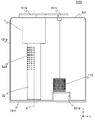
- FIG. 1 is a front view showing an outline of a hydraulic oil tank 100 in which a return filter 1 according to an embodiment of the present invention is provided.
- FIG. 2 is a side view showing an outline of the hydraulic oil tank 100 in which the return filter 1 is provided. 1 and 2, the main part of the hydraulic oil tank 100 is shown through. Moreover, in FIG. 2, the principal part is displayed in cross section (however, hatching indicating the cross section is omitted).
- the hydraulic oil tank 100 is installed in a working machine (not shown) (for example, a hydraulic device), and is a tank for storing hydraulic oil provided in a hydraulic circuit for hydraulic oil supplied to the hydraulic device. is there. In the hydraulic circuit, the hydraulic oil is introduced into the hydraulic oil tank 100 through the hydraulic device.
- a working machine for example, a hydraulic device
- the hydraulic oil is introduced into the hydraulic oil tank 100 through the hydraulic device.
- the hydraulic oil tank 100 includes, for example, a box-shaped tank body 101, and the inside of the tank body 101 is hollow. Inside the tank body 101, a return filter 1 and a suction strainer 110 (see FIG. 1) are mainly provided.
- the return filter 1 is provided adjacent to the wall surface 101e (see FIG. 1) of the tank body 101.
- An inflow port 101a through which hydraulic oil flows into the tank body 101 is formed on the wall surface 101g (see FIG. 2) of the tank body 101.
- the hydraulic oil that has flowed in through the inflow port 101a is guided to the return filter 1.
- the hydraulic oil is filtered by the return filter 1 and stored in the tank body 101.
- lids 101b and 101c used for maintenance of the return filter 1 and the suction strainer 110 are provided at the upper end of the tank body 101.
- the return filter 1 is attached to the lid 101b.
- an outlet 101d (see FIG. 1) through which hydraulic oil in the tank body 101 flows out to a hydraulic pump (not shown) is formed.
- a suction pipe 103 (see FIG. 3) connected to the suction port of a hydraulic pump (not shown) from the outside of the tank body 101 is fitted into the outflow port 101d.
- a suction strainer 110 is provided on the upper side of the outlet 101d (inside the tank body 101) in order to prevent foreign matter from entering the suction pipe 103.
- the hydraulic oil stored in the tank body 101 is sucked by a hydraulic pump (not shown), flows out to the suction pipe 103 via the suction strainer 110, and is supplied to the hydraulic device again.
- the return filter 1 mainly includes a filter case 10, a filter element 20, and a discharge unit 30.
- the filter case 10 is a bottomed substantially cylindrical member and is formed of metal.
- the filter case 10 is integrally formed with the tank body 101 at the upper end.
- the opening at the upper end of the filter case 10 is covered with a lid 101b.
- An inflow hole 10 a for allowing oil to flow into the space inside the filter case 10 is formed on the side surface of the filter case 10.
- the inflow hole 10 a is connected to an inflow port 101 a formed in the tank body 101.
- the hydraulic oil that has flowed in from the inflow port 101a and the inflow hole 10a is guided to the space between the filter case 10 and the filter element 20.
- An outflow hole 10c through which oil filtered by the filter element 20 flows out is formed in the bottom surface 10b of the filter case 10.
- the outflow hole 10c is schematically shown by a dotted line in FIG. Show.
- the filter element 20 is a substantially cylindrical member provided inside the filter case 10.
- a lid 21 is provided at the upper end of the filter element 20, and an elastic member 22 is provided between the lid 21 and the lid 101b.
- the filter element 20 is fixed inside the filter case 10 by pressing the filter element 20 downward ( ⁇ z direction) by the elastic member 22.
- the filter element 20 mainly includes an inner cylinder 23, a filter medium 24, and plates 25 and 26.
- the inner cylinder 23 is a substantially hollow cylindrical member having openings at both ends.
- the inner cylinder 23 is formed using a resin or metal that is a highly corrosion-resistant material.
- the inner cylinder 23 is formed with a hole 23a through which hydraulic oil passes substantially throughout.
- a filter medium 24 is provided outside the inner cylinder 23.
- the filter medium 24 has a substantially cylindrical shape having a thickness in the radial direction.
- the height of the filter medium 24 is substantially the same as the height of the inner cylinder 23.
- the filter medium 24 is formed by folding a filter paper made of synthetic resin, paper, or the like, and connecting both ends of the filter paper that has been folded and rounding it into a cylindrical shape. Thereby, the filter medium 24 is formed in a substantially cylindrical pleat shape.
- the filter medium 24 is for filtering hydraulic oil.
- a plate 25 is provided at one end of the inner cylinder 23 and the filter medium 24, and a plate 26 is provided at the other end.
- the plate 25 and the plate 26 are members having a substantially disc shape or a bottomed substantially cylindrical shape, and are formed using resin or metal.
- the plate 25 and the plate 26 are provided so as to cover the end surfaces of the inner cylinder 23 and the filter medium 24. In other words, the plate 25 and the plate 26 sandwich the inner cylinder 23 and the filter medium 24.
- the plate 25 covers the inner cylinder 23 and the lower end of the filter medium 24.
- the bottom surface of the plate 25 is in contact with the bottom surface 10b, and the inner peripheral surface of the plate 25 is fitted into a first discharge pipe 31 (detailed later).
- a seal member (not shown) that prevents hydraulic oil before filtration from entering the first discharge pipe 31 from between the plate 25 and the filter case 10 is provided on the inner peripheral surface or bottom surface of the plate 25. .
- the plate 26 covers the upper ends of the inner cylinder 23 and the filter medium 24.
- the lid 21 abuts against the plate 26 so that oil before filtration does not flow from the openings of the inner cylinder 23 and the filter medium 24.
- the lid body 21 is provided with a valve 27.
- the valve 27 opens and closes according to the difference between the pressure between the filter case 10 and the filter element 20 (outside the filter element 20) and the pressure inside the filter element 20.
- the outer peripheral surface of the valve 27 is fitted to the inner peripheral surface of the bypass strainer 28.
- the bypass strainer 28 has a substantially cylindrical shape as a whole, and has a mesh-like filtration unit that filters unfiltered oil that flows in when the valve 27 is opened.
- a buffer plate 29 is provided around the filter element 20.
- the buffer plate 29 is a substantially semi-cylindrical plate-like member, and prevents the hydraulic oil flowing in from the inlet 101a and the inflow hole 10a from directly hitting the filter element 20.
- the discharge unit 30 mainly includes a first discharge pipe 31 and a second discharge pipe 32.
- the first discharge pipe 31 and the second discharge pipe 32 are substantially cylindrical members, and are provided to project from the bottom surface 10b toward the bottom surface 101f (downward ( ⁇ z direction)).
- the first discharge pipe 31 is provided coaxially with the second discharge pipe 32 inside the second discharge pipe 32. That is, the central axis A of the first discharge pipe 31 and the central axis A of the second discharge pipe 32 are the same.
- the first discharge pipe 31 has a substantially cylindrical shape having openings at both ends, and is inserted through the inner peripheral surface of the outflow hole 10 c and the inner peripheral surface of the plate 25.
- the outer periphery of the first discharge pipe 31 and the inner periphery of the outflow hole 10c are integrated by welding or the like. No hole is formed on the side surface (cylindrical surface) of the first discharge pipe 31.
- the second discharge pipe 32 has a substantially cylindrical shape with both ends covered, and is provided so as to cover the first discharge pipe 31.
- the diameter of the second discharge pipe 32 is larger than the diameter of the first discharge pipe 31, and the length of the second discharge pipe 32 is longer than the length of the first discharge pipe 31.
- the diameter of the second discharge pipe 32 is such that the difference between the area of the second discharge pipe 32 and the area of the first discharge pipe 31 on the plane orthogonal to the central axis A (hereinafter referred to as the orthogonal plane) It is formed so as to be larger than the area of the first discharge pipe 31.
- the length of the second discharge pipe 32 is determined by the distance between the end 32b of the second discharge pipe 32 and the tip (end 31a) of the first discharge pipe 31 and the area of the second discharge pipe 32.
- the product is formed so as to be equal to or larger than the area of the first discharge pipe 31 in the orthogonal plane.
- the one end 32a of the second discharge pipe 32 is in contact with 10b of the filter case 10, and is integrated by welding or the like.
- the other end 32b of the second discharge pipe 32 is covered with a plate-shaped bottom cover 32c.
- the region in the vicinity of the bottom surface 10b is a region from the upper end of the second discharge pipe 32 to a height of about half, and does not include a portion that contacts the bottom surface 10b.
- the region near the bottom surface 10b is not limited to this form.
- the region in the vicinity of the bottom surface 10b may include a portion that contacts the bottom surface 10b.
- the lower end of the region in the vicinity of the bottom surface 10b may be a position (upward (+ z side)) higher than the position shown in FIGS.
- the diameter of the discharge hole 32d increases as it approaches the bottom surface 10b. That is, the diameter of the discharge hole 32d increases as it approaches the end 32a, and the diameter decreases as it approaches the end 32b.
- the discharge hole 32d is formed only in a substantially half-circumferential region (the left half-circular region in FIG. 1) facing the wall surface 101e. This is to prevent oil flowing between the first discharge pipe 31 and the second discharge pipe 32 from being discharged toward the center of the tank main body 101.
- the discharge holes 32d are formed such that the total area of the discharge holes 32d is equal to or greater than the difference between the area of the second discharge pipe 32 and the area of the first discharge pipe 31 in the orthogonal plane. As a result, the oil flowing between the first discharge pipe 31 and the second discharge pipe 32 is discharged outside the second discharge pipe 32 without staying inside the second discharge pipe 32.
- FIG. 3 is a front view of the main part of the hydraulic oil tank 100 displayed through.
- the main part is shown in cross section (however, hatching indicating the cross section is omitted).
- the oil flow is indicated by arrows.
- the hydraulic oil that has flowed in from the inlet 101a and the inlet hole 10a (not shown in FIG. 3) is guided to the space between the filter case 10 and the filter element 20. Oil that has flowed into the space between the filter case 10 and the filter element 20 is filtered by the filter medium 24. The filtered oil passes through the hole 23 a formed in the inner cylinder 23 and flows into the space inside the inner cylinder 23. The oil after filtration contains bubbles generated during filtration and the like.
- the filtered oil that has flowed into the space inside the inner cylinder 23 flows downward (toward the ⁇ z direction) inside the first discharge pipe 31, and an opening formed at the end 31 a of the first discharge pipe 31. To the inside of the second discharge pipe 32.
- the oil that has flowed into the second discharge pipe 32 is between the first discharge pipe 31 and the second discharge pipe 32. Flows upward (toward the + z direction).
- the oil that has flowed upward in the space between the first discharge pipe 31 and the second discharge pipe 32 is discharged into the tank body 101 from the discharge hole 32d. Since the diameter of the discharge hole 32d increases as it approaches the bottom surface 10b, more oil flows out from a hole located above the discharge hole 32d (a hole close to the bottom surface 10b). As a result, as much oil as possible, that is, the bubbles B, can be discharged to a position close to the oil level. Further, since the oil flows upward in the space between the first discharge pipe 31 and the second discharge pipe 32, the discharged oil and the bubbles B flow upward toward the oil surface. Therefore, the bubbles B are not discharged in the vicinity of the bottom surface 101f, and the bubbles B can be hardly sucked into the suction strainer 110.
- the discharge hole 32d is formed only in a substantially half-circumferential region (region on the left half in FIG. 3) facing the wall surface 101e. Therefore, the oil flowing through the space between the first discharge pipe 31 and the second discharge pipe 32 is discharged only on the left side in FIG. 3, and is not discharged on the right side in FIG. That is, the oil discharged from the return filter 1 is discharged toward the wall surface 101e, but is not discharged toward the center of the tank body 101, that is, toward the suction strainer 110. As a result, it is possible to make it difficult for the bubbles B contained in the oil discharged from the return filter 1 to be sucked into the suction strainer 110.
- the present embodiment it is possible to discharge the oil filtered by the return filter 1 (that is, the bubbles B) from a position close to the oil surface and not to the vicinity of the bottom surface 101f. As a result, the bubbles B are less likely to be sucked into the suction strainer 110, and failure of the pump or the like can be reduced.
- the oil filtered with the return filter 1 is discharged
- the bubbles B contained in the air are more difficult to be sucked into the suction strainer 110.
- FIG. 5 is a front view showing an outline of a hydraulic oil tank 100 ′ in which a conventional return filter 1 ′ is provided. Since oil containing bubbles is discharged from the return filter 1 ′ toward the suction strainer 110, a partition plate 111 is provided to prevent the suction strainer 110 from sucking bubbles, and oil discharged from the return filter 1 ′ (bubbles) It was necessary to prevent it from directly hitting the suction strainer 110. However, in the present embodiment, since the oil filtered by the return filter 1 is discharged only from a substantially half-circumferential region facing the wall surface 101e, the partition plate 111 becomes unnecessary. Thereby, the configuration of the hydraulic oil tank 100 can be simplified and the cost can be reduced.
- the lengths of the first discharge pipe 31 and the second discharge pipe 32 are set so that the end 32b of the second discharge pipe 32 is positioned in the vicinity of the bottom surface 101f.
- the lengths of the discharge pipe 31 and the second discharge pipe 32 are not limited to this. However, in order to make the oil discharged from the discharge holes 32d and the bubbles B easily flow upward toward the oil surface, the lengths of the first discharge pipe 31 and the second discharge pipe 32 should be made as long as possible. desirable.
- the discharge hole 32d is formed in a substantially half circumference of the second discharge pipe 32. However, depending on the size of the tank main body 101 and the arrangement position of the suction strainer 110, the discharge hole 32d is formed in the second discharge pipe 32d. You may form in the perimeter of the discharge pipe 32. FIG.
- the end 32b of the second discharge pipe 32 is covered by the plate-shaped bottom cover 32c, but the form covering the end 32b is not limited to this.
- the end 32b of the second discharge pipe 32 is covered with a bottom cover having a substantially truncated cone shape.
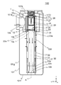
- the return filter 2 according to the second embodiment will be described.
- the difference between the return filter 1 and the return filter 2 is only the bottom cover that covers the end 32b, and the description of the same parts in the return filter 1 and the return filter 2 is omitted.
- FIG. 4 is a side view showing an outline of a hydraulic oil tank 100A in which the return filter 2 is provided.
- the essential part of the hydraulic oil tank 100 is seen through and shown in cross section (however, hatching indicating the cross section is omitted).
- the flow of oil is indicated by arrows.
- the discharge unit 30A mainly includes a first discharge pipe 31 and a second discharge pipe 32A.
- the end 32b of the second discharge pipe 32A is covered with a bottom cover 32e.
- the bottom cover 32e has a substantially truncated cone shape, and is provided so that the tip 32f projects into the second discharge pipe 32A (projects upward).
- the oil that flows downward in the first discharge pipe 31 collides with the bottom cover 32e and flows along the bottom cover 32e toward the outer peripheral surface of the second discharge pipe 32A. Thereafter, the oil collides with the outer peripheral surface of the second discharge pipe 32A and changes to an upward flow.
- the bottom cover 32e by forming the bottom cover 32e in a substantially truncated cone shape, oil flows along the bottom cover 32e, and the oil flow can be naturally formed. Therefore, an upward flow is created in the oil that flows downward from the first discharge pipe 31 into the second discharge pipe 32, and the oil that flows upward naturally forms the first discharge pipe 31 and the second discharge pipe. 32 can flow into the space between the two. Further, when the oil collides with the bottom cover 32e, it is possible to prevent the generation of the bubbles B inside the oil.
- substantially is a concept that includes not only a case where they are exactly the same but also errors and deformations that do not lose the identity.
- substantially half is not limited to exactly half, and is a concept including an error that does not lose the identity (for example, an error of several millimeters).
- orthogonal, parallel, identical, etc. not only strictly orthogonal, parallel, coincident, etc. but also cases of substantially parallel, substantially orthogonal, substantially identical, etc. are included.
- neighboring means including an area in a certain range (which can be arbitrarily determined) near the reference position.
- a certain range which can be arbitrarily determined
Abstract
In order to prevent discharge of bubbles near the bottom surface of a tank, an approximately cylindrical first discharge tube (31) having an opening at both ends is inserted into an outflow hole (10c) of a filter case (19) and is disposed to project towards the bottom surface of the tank. An approximately cylindrical second discharge tube (32) is provided to cover the first discharge tube (31). The second discharge tube (32) is disposed such that a first end (32a) contacts the bottom surface (10b) of the filter case and so as to project from the bottom surface (10b) of the filter case towards the bottom surface of the tank. The leading end (32b) of the second discharge tube (32) is covered by a bottom surface cover (32c), and multiple discharge holes (32d) are formed in a region near the upper end of the lateral surface. For that reason, oil discharged from the outflow hole (10c) flows downwards through the first discharge tube (31), then flows upwards between the first discharge tube (31) and the second discharge tube (32), and is discharged from the region near the upper end of the second discharge tube (32).
Description
本発明は、リターンフィルタに関する。
The present invention relates to a return filter.
特許文献1には、濾過エレメントの下方に突出するように油密保持筒が設けられ、油密保持筒の先端から横方向に突出するように多数の小孔を有するディフューザーが設けられたリターン回路用フィルタが開示されている。
Patent Document 1 discloses a return circuit in which an oil tight holding cylinder is provided so as to protrude below the filter element, and a diffuser having a large number of small holes is provided so as to protrude laterally from the tip of the oil tight holding cylinder. A filter is disclosed.
しかしながら、特許文献1に記載の発明では、ディフューザーから流出した油がタンクの底面にぶつかり、それによりタンク底面近傍で泡が発生するおそれがある。タンク底面近傍で発生した泡はサクションストレーナに流入しやすいため、タンク底面近傍からはできるだけ泡を無くすことが好ましい。
However, in the invention described in Patent Document 1, the oil that has flowed out of the diffuser collides with the bottom surface of the tank, which may cause bubbles in the vicinity of the tank bottom surface. Foam generated in the vicinity of the tank bottom tends to flow into the suction strainer. Therefore, it is preferable to eliminate bubbles from the vicinity of the tank bottom as much as possible.
本発明はこのような事情に鑑みてなされたもので、タンク底面近傍に泡を排出しないようにすることができるリターンフィルタを提供することを目的とする。
The present invention has been made in view of such circumstances, and an object thereof is to provide a return filter capable of preventing bubbles from being discharged near the bottom of a tank.
上記課題を解決するために、本発明に係るリターンフィルタは、例えば、タンクの内部に設けられるリターンフィルタであって、略円筒状の濾材を有するフィルタエレメントと、前記フィルタエレメントが内部に設けられた有底略円筒形状のフィルタケースであって、側面に流入孔が形成されるとともに、底面に流出孔が形成されたフィルタケースと、両端に開口を有する略円筒形状の第1の排出管であって、前記流出孔に挿通され、前記タンクの底面に向かって突出して設けられる第1の排出管と、前記第1の排出管を覆うように、かつ前記フィルタケースの底面から前記タンクの底面に向かって突出して設けられる略円筒形状の第2の排出管であって、第1の端は前記フィルタケースの底面に当接し、前記第1の端以外の端である第2の端は底面カバーにより覆われ、側面の前記フィルタケースの底面近傍の領域に複数の排出孔が形成される第2の排出管と、を備えたことを特徴とする。
In order to solve the above problems, a return filter according to the present invention is, for example, a return filter provided in a tank, and includes a filter element having a substantially cylindrical filter medium, and the filter element provided therein. A bottomed substantially cylindrical filter case, which includes an inflow hole formed in the side surface and an outflow hole formed in the bottom surface, and a substantially cylindrical first discharge pipe having openings at both ends. A first discharge pipe that is inserted through the outflow hole and protrudes toward the bottom surface of the tank, and covers the first discharge pipe from the bottom surface of the filter case to the bottom surface of the tank. A second discharge pipe having a substantially cylindrical shape and projecting toward the second end, the first end being in contact with the bottom surface of the filter case, and a second end other than the first end. End is covered by a bottom cover, characterized by comprising a second discharge pipe having a plurality of discharge holes in a region near the bottom of the filter case side is formed, the.
本発明に係るリターンフィルタによれば、両端に開口を有する略円筒形状の第1の排出管は、フィルタケースの流出孔に挿通され、フィルタケースの底面からタンクの底面に向かって突出して設けられる。略円筒形状の第2の排出管は、第1の排出管を覆うように、フィルタケースの底面からタンクの底面に向かって突出して設けられる。第2の排出管は、第1の端がフィルタケースの底面に当接し、第2の端が底面カバーにより覆われる。第2の排出管の側面には、フィルタケースの底面近傍の領域(上端近傍の領域)に複数の排出孔が形成される。このため、フィルタケースの流出孔から排出された油は、第1の排出管を下向きに流れ、その後第1の排出管と第2の排出管との間を上向きに流れ、フィルタケースの底面近傍の領域のみから排出される。これにより、タンク底面近傍に泡を排出しないようにすることができる。
According to the return filter of the present invention, the substantially cylindrical first discharge pipe having openings at both ends is inserted into the outflow hole of the filter case, and is provided to protrude from the bottom surface of the filter case toward the bottom surface of the tank. . The substantially cylindrical second discharge pipe is provided so as to protrude from the bottom surface of the filter case toward the bottom surface of the tank so as to cover the first discharge pipe. As for a 2nd discharge pipe, the 1st end contacts the bottom of a filter case, and the 2nd end is covered with a bottom cover. On the side surface of the second discharge pipe, a plurality of discharge holes are formed in an area near the bottom surface of the filter case (an area near the upper end). For this reason, the oil discharged from the outflow hole of the filter case flows downward in the first discharge pipe, and then flows upward between the first discharge pipe and the second discharge pipe, near the bottom surface of the filter case. It is discharged only from the area. Thereby, it is possible to prevent bubbles from being discharged near the bottom of the tank.
ここで、前記排出孔は、前記フィルタケースの底面に近づくにつれて直径が大きくなってもよい。このように、排出孔のうちのより上方に位置する孔からより多くの油を流出させることで、できるだけ多くの油(気泡を含む)を油面に近い位置で排出することができる。
Here, the diameter of the discharge hole may increase as it approaches the bottom surface of the filter case. In this way, by causing more oil to flow out of the holes located above the discharge holes, as much oil (including bubbles) as possible can be discharged at a position close to the oil level.
ここで、前記排出孔は、前記排出孔の面積の合計が、前記第2の排出管の中心軸と直交する断面における前記第2の排出管の面積と前記第1の排出管の面積との差以上となるように形成してもよい。これにより、第1の排出管と第2の排出管との間を流れる油を、第2の排出管の内部に滞留させずに外部に排出させることができる。
Here, the discharge hole has a total area of the discharge holes, the area of the second discharge pipe and the area of the first discharge pipe in a cross section orthogonal to the central axis of the second discharge pipe. You may form so that it may become more than a difference. Thereby, the oil which flows between the 1st discharge pipe and the 2nd discharge pipe can be discharged outside, without staying in the inside of the 2nd discharge pipe.
ここで、前記タンクの第1の壁面に隣接して設けられたリターンフィルタであって、前記排出孔は、前記第1の壁面と対向する略半周の領域にのみ形成されてもよい。このように、リターンフィルタから排出される油を第1の壁面に向けて排出させることで、リターンフィルタから排出される油がサクションストレーナに向けて排出されないようにすることができる。その結果、リターンフィルタから排出される油に含まれる気泡が、サクションストレーナに吸い込まれにくくなる。
Here, in the return filter provided adjacent to the first wall surface of the tank, the discharge hole may be formed only in a substantially half-circumferential region facing the first wall surface. Thus, by discharging the oil discharged from the return filter toward the first wall surface, it is possible to prevent the oil discharged from the return filter from being discharged toward the suction strainer. As a result, bubbles included in the oil discharged from the return filter are not easily sucked into the suction strainer.
ここで、前記底面カバーは、先端が前記第2の排出管の内部に突出する略円錐台形状であってもよい。これにより、底面カバーに沿って油を流すことで、油の流れを自然に形成し、気泡の発生を減らすことができる。
Here, the bottom cover may have a substantially frustoconical shape with a tip projecting into the second discharge pipe. Thereby, by flowing oil along a bottom cover, the flow of oil can be formed naturally and the generation of bubbles can be reduced.
本発明によれば、タンク底面近傍に泡を排出しないようにすることができる。
According to the present invention, it is possible to prevent bubbles from being discharged near the bottom of the tank.
以下、本発明の実施形態を、図面を参照して詳細に説明する。
Hereinafter, embodiments of the present invention will be described in detail with reference to the drawings.
<第1の実施の形態>
図1は、本発明の一実施形態であるリターンフィルタ1が内部に設けられた作動油タンク100の概略を示す正面図である。図2は、リターンフィルタ1が内部に設けられた作動油タンク100の概略を示す側面図である。図1、2では、作動油タンク100の要部を透視して図示している。また、図2においては、要部を断面表示している(ただし、断面を示すハッチングを省略している)。 <First Embodiment>
FIG. 1 is a front view showing an outline of ahydraulic oil tank 100 in which a return filter 1 according to an embodiment of the present invention is provided. FIG. 2 is a side view showing an outline of the hydraulic oil tank 100 in which the return filter 1 is provided. 1 and 2, the main part of the hydraulic oil tank 100 is shown through. Moreover, in FIG. 2, the principal part is displayed in cross section (however, hatching indicating the cross section is omitted).
図1は、本発明の一実施形態であるリターンフィルタ1が内部に設けられた作動油タンク100の概略を示す正面図である。図2は、リターンフィルタ1が内部に設けられた作動油タンク100の概略を示す側面図である。図1、2では、作動油タンク100の要部を透視して図示している。また、図2においては、要部を断面表示している(ただし、断面を示すハッチングを省略している)。 <First Embodiment>
FIG. 1 is a front view showing an outline of a
作動油タンク100は、図示しない作業機械(例えば、油圧装置)に設置されるものであり、この油圧装置へ供給する作動油の油圧回路内に設けられた、作動油を貯留するためのタンクである。油圧回路において、作動油は、油圧装置を通って作動油タンク100へ導入される。
The hydraulic oil tank 100 is installed in a working machine (not shown) (for example, a hydraulic device), and is a tank for storing hydraulic oil provided in a hydraulic circuit for hydraulic oil supplied to the hydraulic device. is there. In the hydraulic circuit, the hydraulic oil is introduced into the hydraulic oil tank 100 through the hydraulic device.
作動油タンク100は、例えば箱形のタンク本体101を備えており、このタンク本体101はその内部が空洞となっている。タンク本体101の内部には、主として、リターンフィルタ1と、サクションストレーナ110(図1参照)と、が設けられる。
The hydraulic oil tank 100 includes, for example, a box-shaped tank body 101, and the inside of the tank body 101 is hollow. Inside the tank body 101, a return filter 1 and a suction strainer 110 (see FIG. 1) are mainly provided.
リターンフィルタ1は、タンク本体101の壁面101e(図1参照)に隣接して設けられる。タンク本体101の壁面101g(図2参照)には、作動油をタンク本体101の内部へ流入させる流入口101aが形成される。流入口101aを介して流入した作動油は、リターンフィルタ1に導かれる。作動油は、リターンフィルタ1によって濾過されて、タンク本体101内に貯留される。
The return filter 1 is provided adjacent to the wall surface 101e (see FIG. 1) of the tank body 101. An inflow port 101a through which hydraulic oil flows into the tank body 101 is formed on the wall surface 101g (see FIG. 2) of the tank body 101. The hydraulic oil that has flowed in through the inflow port 101a is guided to the return filter 1. The hydraulic oil is filtered by the return filter 1 and stored in the tank body 101.
また、タンク本体101の上端部には、リターンフィルタ1やサクションストレーナ110のメンテナンス等に利用する蓋101b、101cが設けられる。蓋101bには、リターンフィルタ1が取り付けられる。
Further, lids 101b and 101c used for maintenance of the return filter 1 and the suction strainer 110 are provided at the upper end of the tank body 101. The return filter 1 is attached to the lid 101b.
タンク本体101の底面101f近傍には、タンク本体101内の作動油を油圧ポンプ(図示せず)へ流出させる流出口101d(図1参照)が形成される。流出口101dには、タンク本体101の外側から、油圧ポンプ(図示せず)の吸い込みポートへ繋がるサクションパイプ103(図3参照)が嵌挿されている。
In the vicinity of the bottom surface 101f of the tank body 101, an outlet 101d (see FIG. 1) through which hydraulic oil in the tank body 101 flows out to a hydraulic pump (not shown) is formed. A suction pipe 103 (see FIG. 3) connected to the suction port of a hydraulic pump (not shown) from the outside of the tank body 101 is fitted into the outflow port 101d.
流出口101dの上側(タンク本体101の内側)には、サクションパイプ103への異物の進入を防止するため、サクションストレーナ110が設けられる。タンク本体101内に貯留された作動油は、油圧ポンプ(図示せず)に吸引されて、サクションストレーナ110を介してサクションパイプ103へ流出し、再度油圧装置へ供給される。
A suction strainer 110 is provided on the upper side of the outlet 101d (inside the tank body 101) in order to prevent foreign matter from entering the suction pipe 103. The hydraulic oil stored in the tank body 101 is sucked by a hydraulic pump (not shown), flows out to the suction pipe 103 via the suction strainer 110, and is supplied to the hydraulic device again.
次に、図2を用いてリターンフィルタ1について説明する。図2においては、油の流れを矢印で示す。リターンフィルタ1は、主として、フィルタケース10と、フィルタエレメント20と、排出部30と、を有する。
Next, the return filter 1 will be described with reference to FIG. In FIG. 2, the oil flow is indicated by arrows. The return filter 1 mainly includes a filter case 10, a filter element 20, and a discharge unit 30.
フィルタケース10は、有底略円筒形状の部材であり、金属により形成される。フィルタケース10は、上端がタンク本体101と一体形成されている。また、フィルタケース10の上端の開口部は、蓋101bにより覆われる。
The filter case 10 is a bottomed substantially cylindrical member and is formed of metal. The filter case 10 is integrally formed with the tank body 101 at the upper end. The opening at the upper end of the filter case 10 is covered with a lid 101b.
フィルタケース10の側面には、フィルタケース10内部の空間に油を流入させる流入孔10aが形成される。流入孔10aは、タンク本体101に形成された流入口101aと連結されている。流入口101a及び流入孔10aから流入した作動油は、フィルタケース10とフィルタエレメント20との間の空間に導かれる。
An inflow hole 10 a for allowing oil to flow into the space inside the filter case 10 is formed on the side surface of the filter case 10. The inflow hole 10 a is connected to an inflow port 101 a formed in the tank body 101. The hydraulic oil that has flowed in from the inflow port 101a and the inflow hole 10a is guided to the space between the filter case 10 and the filter element 20.
フィルタケース10の底面10bには、フィルタエレメント20により濾過された油が流出する流出孔10cが形成される。本実施の形態では、流出孔10cの内周面に第1の排出管31(後の詳述)が挿入されて一体化されているため、図2においては流出孔10cを点線で模式的に示す。
An outflow hole 10c through which oil filtered by the filter element 20 flows out is formed in the bottom surface 10b of the filter case 10. In the present embodiment, since the first discharge pipe 31 (described later in detail) is inserted and integrated with the inner peripheral surface of the outflow hole 10c, the outflow hole 10c is schematically shown by a dotted line in FIG. Show.
フィルタエレメント20は、フィルタケース10の内部に設けられる略円筒状の部材である。フィルタエレメント20の上端には蓋体21が設けられ、蓋体21と蓋101bとの間には弾性部材22が設けられる。弾性部材22によりフィルタエレメント20が下方(-z方向)に押圧されることで、フィルタケース10の内部でフィルタエレメント20が固定される。
The filter element 20 is a substantially cylindrical member provided inside the filter case 10. A lid 21 is provided at the upper end of the filter element 20, and an elastic member 22 is provided between the lid 21 and the lid 101b. The filter element 20 is fixed inside the filter case 10 by pressing the filter element 20 downward (−z direction) by the elastic member 22.
フィルタエレメント20は、主として、内筒23と、濾材24と、プレート25、26と、を有する。
The filter element 20 mainly includes an inner cylinder 23, a filter medium 24, and plates 25 and 26.
内筒23は、両端に開口を有する略中空円筒形状の部材である。内筒23は、耐腐食性の高い材料である樹脂又は金属を用いて形成される。内筒23には、略全域に作動油が通過する孔23aが形成されている。
The inner cylinder 23 is a substantially hollow cylindrical member having openings at both ends. The inner cylinder 23 is formed using a resin or metal that is a highly corrosion-resistant material. The inner cylinder 23 is formed with a hole 23a through which hydraulic oil passes substantially throughout.
内筒23の外側には、濾材24が設けられる。濾材24は、径方向に厚みを有する略円筒形状である。濾材24の高さは、内筒23の高さと略同一である。濾材24は、合成樹脂や紙等を用いたろ紙をひだ折りにし、ひだ折りにしたろ紙の両端を連結して円筒状に丸めることによって形成される。これにより、濾材24は、略円筒プリーツ形状に形成される。濾材24は作動油を濾過するためのものである。
A filter medium 24 is provided outside the inner cylinder 23. The filter medium 24 has a substantially cylindrical shape having a thickness in the radial direction. The height of the filter medium 24 is substantially the same as the height of the inner cylinder 23. The filter medium 24 is formed by folding a filter paper made of synthetic resin, paper, or the like, and connecting both ends of the filter paper that has been folded and rounding it into a cylindrical shape. Thereby, the filter medium 24 is formed in a substantially cylindrical pleat shape. The filter medium 24 is for filtering hydraulic oil.
内筒23及び濾材24の一方の端にはプレート25が設けられ、他方の端にはプレート26が設けられる。プレート25及びプレート26は、略円板状又は有底略円筒形状の部材であり、樹脂又は金属を用いて形成される。
A plate 25 is provided at one end of the inner cylinder 23 and the filter medium 24, and a plate 26 is provided at the other end. The plate 25 and the plate 26 are members having a substantially disc shape or a bottomed substantially cylindrical shape, and are formed using resin or metal.
プレート25及びプレート26は、内筒23及び濾材24の端面を覆うように設けられる。言い換えると、プレート25及びプレート26は、内筒23及び濾材24を挟持する。
The plate 25 and the plate 26 are provided so as to cover the end surfaces of the inner cylinder 23 and the filter medium 24. In other words, the plate 25 and the plate 26 sandwich the inner cylinder 23 and the filter medium 24.
プレート25は、内筒23及び濾材24の下端を覆う。プレート25の底面は、底面10bに当接し、プレート25の内周面は第1の排出管31(後に詳述)に嵌合する。
The plate 25 covers the inner cylinder 23 and the lower end of the filter medium 24. The bottom surface of the plate 25 is in contact with the bottom surface 10b, and the inner peripheral surface of the plate 25 is fitted into a first discharge pipe 31 (detailed later).
プレート25の内周面又は底面には、プレート25とフィルタケース10との間から、濾過前の作動油が第1の排出管31に侵入しないようにするシール部材(図示せず)が設けられる。
A seal member (not shown) that prevents hydraulic oil before filtration from entering the first discharge pipe 31 from between the plate 25 and the filter case 10 is provided on the inner peripheral surface or bottom surface of the plate 25. .
プレート26は、内筒23及び濾材24の上端を覆う。プレート26には、内筒23及び濾材24の開口部から濾過前の油が流入しないように、蓋体21が当接する。
The plate 26 covers the upper ends of the inner cylinder 23 and the filter medium 24. The lid 21 abuts against the plate 26 so that oil before filtration does not flow from the openings of the inner cylinder 23 and the filter medium 24.
蓋体21には、バルブ27が設けられる。バルブ27は、フィルタケース10とフィルタエレメント20との間(フィルタエレメント20の外側)の圧力と、フィルタエレメント20の内側の圧力との差に応じて開閉する。バルブ27の外周面は、バイパスストレーナ28の内周面に嵌合する。
The lid body 21 is provided with a valve 27. The valve 27 opens and closes according to the difference between the pressure between the filter case 10 and the filter element 20 (outside the filter element 20) and the pressure inside the filter element 20. The outer peripheral surface of the valve 27 is fitted to the inner peripheral surface of the bypass strainer 28.
バイパスストレーナ28は、全体として略円筒形状であり、バルブ27が開いたときに流入する未濾過の油を濾過するメッシュ状の濾過部を有する。
The bypass strainer 28 has a substantially cylindrical shape as a whole, and has a mesh-like filtration unit that filters unfiltered oil that flows in when the valve 27 is opened.
フィルタエレメント20の周囲には、バッファ板29が設けられる。バッファ板29は、略半円筒形の板状の部材であり、流入口101a及び流入孔10aから流入した作動油が直接フィルタエレメント20に当たらないようにする。
A buffer plate 29 is provided around the filter element 20. The buffer plate 29 is a substantially semi-cylindrical plate-like member, and prevents the hydraulic oil flowing in from the inlet 101a and the inflow hole 10a from directly hitting the filter element 20.
排出部30は、主として、第1の排出管31と、第2の排出管32と、を有する。第1の排出管31及び第2の排出管32は、略円筒形状の部材であり、底面10bから底面101fに向かって(下方(-z方向)に)突出して設けられる。
The discharge unit 30 mainly includes a first discharge pipe 31 and a second discharge pipe 32. The first discharge pipe 31 and the second discharge pipe 32 are substantially cylindrical members, and are provided to project from the bottom surface 10b toward the bottom surface 101f (downward (−z direction)).
第1の排出管31は、第2の排出管32の内部に、第2の排出管32と同軸上に設けられる。つまり、第1の排出管31の中心軸Aと第2の排出管32の中心軸Aとは同一である。
The first discharge pipe 31 is provided coaxially with the second discharge pipe 32 inside the second discharge pipe 32. That is, the central axis A of the first discharge pipe 31 and the central axis A of the second discharge pipe 32 are the same.
第1の排出管31は、両端に開口を有する略円筒形状であり、流出孔10cの内周面及びプレート25の内周面に挿通される。第1の排出管31の外周と流出孔10cの内周とは、溶接等により一体化される。第1の排出管31の側面(円筒面)には、孔は形成されていない。
The first discharge pipe 31 has a substantially cylindrical shape having openings at both ends, and is inserted through the inner peripheral surface of the outflow hole 10 c and the inner peripheral surface of the plate 25. The outer periphery of the first discharge pipe 31 and the inner periphery of the outflow hole 10c are integrated by welding or the like. No hole is formed on the side surface (cylindrical surface) of the first discharge pipe 31.
第2の排出管32は、両端が覆われた略円筒形状であり、第1の排出管31を覆うように設けられる。第2の排出管32の直径は、第1の排出管31の直径よりも大きく、第2の排出管32の長さは、第1の排出管31の長さよりも長い。
The second discharge pipe 32 has a substantially cylindrical shape with both ends covered, and is provided so as to cover the first discharge pipe 31. The diameter of the second discharge pipe 32 is larger than the diameter of the first discharge pipe 31, and the length of the second discharge pipe 32 is longer than the length of the first discharge pipe 31.
第2の排出管32の直径は、中心軸Aと直交する面(以下、直交面という)における第2の排出管32の面積と第1の排出管31の面積との差が、直交面における第1の排出管31の面積以上となるように形成される。また、第2の排出管32の長さは、第2の排出管32の端32bと第1の排出管31の先端(端31a)との距離と、第2の排出管32の面積との積が、直交面における第1の排出管31の面積以上となるように形成される。これにより、第1の排出管31から排出された油が、第1の排出管31と第2の排出管32との間に安定して流入する。
The diameter of the second discharge pipe 32 is such that the difference between the area of the second discharge pipe 32 and the area of the first discharge pipe 31 on the plane orthogonal to the central axis A (hereinafter referred to as the orthogonal plane) It is formed so as to be larger than the area of the first discharge pipe 31. The length of the second discharge pipe 32 is determined by the distance between the end 32b of the second discharge pipe 32 and the tip (end 31a) of the first discharge pipe 31 and the area of the second discharge pipe 32. The product is formed so as to be equal to or larger than the area of the first discharge pipe 31 in the orthogonal plane. As a result, the oil discharged from the first discharge pipe 31 stably flows between the first discharge pipe 31 and the second discharge pipe 32.
第2の排出管32の一方の端32aはフィルタケース10の10bに当接し、溶接等により一体化される。第2の排出管32の他方の端32bは、板状の底面カバー32cにより覆われる。
The one end 32a of the second discharge pipe 32 is in contact with 10b of the filter case 10, and is integrated by welding or the like. The other end 32b of the second discharge pipe 32 is covered with a plate-shaped bottom cover 32c.
第2の排出管32の側面(円筒面)には、底面10b近傍の領域(第2の排出管32の上端近傍の領域)に複数の排出孔32dが形成される。本実施の形態においては、底面10b近傍の領域とは、第2の排出管32の上端から略半分程度の高さまでの領域であり、底面10bと当接する部分を含まない。ただし、底面10b近傍の領域はこの形態に限定されない。例えば、底面10b近傍の領域は、底面10bと当接する部分を含んでもよい。また、底面10b近傍の領域の下端は、図1、2に示す位置よりも高い位置(上方(+z側))でもよい。
On the side surface (cylindrical surface) of the second discharge pipe 32, a plurality of discharge holes 32d are formed in an area near the bottom surface 10b (an area near the upper end of the second discharge pipe 32). In the present embodiment, the region in the vicinity of the bottom surface 10b is a region from the upper end of the second discharge pipe 32 to a height of about half, and does not include a portion that contacts the bottom surface 10b. However, the region near the bottom surface 10b is not limited to this form. For example, the region in the vicinity of the bottom surface 10b may include a portion that contacts the bottom surface 10b. Further, the lower end of the region in the vicinity of the bottom surface 10b may be a position (upward (+ z side)) higher than the position shown in FIGS.
図1に示すように、排出孔32dは、底面10bに近づくにつれて直径が大きくなる。つまり、排出孔32dは、端32aに近づくにつれて直径が大きくなり、端32bに近づくにつれて直径が小さくなる。
As shown in FIG. 1, the diameter of the discharge hole 32d increases as it approaches the bottom surface 10b. That is, the diameter of the discharge hole 32d increases as it approaches the end 32a, and the diameter decreases as it approaches the end 32b.
また、排出孔32dは、壁面101eと対向する略半周の領域(図1においては、左側半周の領域)にのみ形成される。これは、第1の排出管31と第2の排出管32との間を流れる油が、タンク本体101の中央に向けて排出されないようにするためである。
Further, the discharge hole 32d is formed only in a substantially half-circumferential region (the left half-circular region in FIG. 1) facing the wall surface 101e. This is to prevent oil flowing between the first discharge pipe 31 and the second discharge pipe 32 from being discharged toward the center of the tank main body 101.
排出孔32dは、排出孔32dの面積の合計が、直交面における第2の排出管32の面積と第1の排出管31の面積との差以上となるように形成される。これにより、第1の排出管31と第2の排出管32との間を流れる油が、第2の排出管32の内部に滞留せずに第2の排出管32外部に排出される。
The discharge holes 32d are formed such that the total area of the discharge holes 32d is equal to or greater than the difference between the area of the second discharge pipe 32 and the area of the first discharge pipe 31 in the orthogonal plane. As a result, the oil flowing between the first discharge pipe 31 and the second discharge pipe 32 is discharged outside the second discharge pipe 32 without staying inside the second discharge pipe 32.
次に、リターンフィルタ1及びタンク本体101内の油の流れを、図3を用いて説明する。図3は、作動油タンク100の要部を透視して表示した正面図である。図3においては、要部を断面表示している(ただし、断面を示すハッチングを省略している)。図3においては、油の流れを矢印で示す。
Next, the flow of oil in the return filter 1 and the tank body 101 will be described with reference to FIG. FIG. 3 is a front view of the main part of the hydraulic oil tank 100 displayed through. In FIG. 3, the main part is shown in cross section (however, hatching indicating the cross section is omitted). In FIG. 3, the oil flow is indicated by arrows.
流入口101a及び流入孔10a(図3では図示せず)から流入した作動油は、フィルタケース10とフィルタエレメント20との間の空間に導かれる。フィルタケース10とフィルタエレメント20との間の空間に流入した油は、濾材24で濾過される。濾過後の油は、内筒23に形成された孔23aを通過して、内筒23の内側の空間に流入する。この濾過後の油には、濾過時等に発生した気泡が含まれている。
The hydraulic oil that has flowed in from the inlet 101a and the inlet hole 10a (not shown in FIG. 3) is guided to the space between the filter case 10 and the filter element 20. Oil that has flowed into the space between the filter case 10 and the filter element 20 is filtered by the filter medium 24. The filtered oil passes through the hole 23 a formed in the inner cylinder 23 and flows into the space inside the inner cylinder 23. The oil after filtration contains bubbles generated during filtration and the like.
内筒23の内側の空間に流入した濾過後の油は、第1の排出管31内部を下向きに(-z方向に向かって)流れ、第1の排出管31の端31aに形成された開口から第2の排出管32の内部に排出される。
The filtered oil that has flowed into the space inside the inner cylinder 23 flows downward (toward the −z direction) inside the first discharge pipe 31, and an opening formed at the end 31 a of the first discharge pipe 31. To the inside of the second discharge pipe 32.
第2の排出管32の端32bは底面カバー32cにより覆われているため、第2の排出管32の内部に流入した油は、第1の排出管31と第2の排出管32との間の空間を上向きに(+z方向に向かって)流れる。
Since the end 32 b of the second discharge pipe 32 is covered with the bottom cover 32 c, the oil that has flowed into the second discharge pipe 32 is between the first discharge pipe 31 and the second discharge pipe 32. Flows upward (toward the + z direction).
第1の排出管31と第2の排出管32との間の空間を上向きに流れた油は、排出孔32dからタンク本体101の内部に排出される。排出孔32dは、底面10bに近づくにつれて直径が大きくなるため、排出孔32dのうちのより上方に位置する孔(底面10bに近い孔)からより多くの油が流出する。これにより、油面に近い位置に、できるだけ多くの油、すなわち気泡Bを排出することができる。また、油は第1の排出管31と第2の排出管32との間の空間を上向きに流れているため、排出された油及び気泡Bは、油面に向けて上側へ流れる。したがって、底面101fの近傍に気泡Bが排出されず、気泡Bがサクションストレーナ110に吸い込まれにくくすることができる。
The oil that has flowed upward in the space between the first discharge pipe 31 and the second discharge pipe 32 is discharged into the tank body 101 from the discharge hole 32d. Since the diameter of the discharge hole 32d increases as it approaches the bottom surface 10b, more oil flows out from a hole located above the discharge hole 32d (a hole close to the bottom surface 10b). As a result, as much oil as possible, that is, the bubbles B, can be discharged to a position close to the oil level. Further, since the oil flows upward in the space between the first discharge pipe 31 and the second discharge pipe 32, the discharged oil and the bubbles B flow upward toward the oil surface. Therefore, the bubbles B are not discharged in the vicinity of the bottom surface 101f, and the bubbles B can be hardly sucked into the suction strainer 110.
排出孔32dは、壁面101eと対向する略半周の領域(図3における左側半周の領域)にのみ形成される。したがって、第1の排出管31と第2の排出管32との間の空間を流れる油は、図3における左側にのみ排出され、図3における右側には排出されない。つまり、リターンフィルタ1から排出される油は、壁面101eに向けて排出されるが、タンク本体101の中央に向けて、すなわちサクションストレーナ110に向けて排出されない。その結果、リターンフィルタ1から排出される油に含まれる気泡Bが、サクションストレーナ110に吸い込まれにくくすることができる。
The discharge hole 32d is formed only in a substantially half-circumferential region (region on the left half in FIG. 3) facing the wall surface 101e. Therefore, the oil flowing through the space between the first discharge pipe 31 and the second discharge pipe 32 is discharged only on the left side in FIG. 3, and is not discharged on the right side in FIG. That is, the oil discharged from the return filter 1 is discharged toward the wall surface 101e, but is not discharged toward the center of the tank body 101, that is, toward the suction strainer 110. As a result, it is possible to make it difficult for the bubbles B contained in the oil discharged from the return filter 1 to be sucked into the suction strainer 110.
本実施の形態によれば、リターンフィルタ1で濾過された油(すなわち気泡B)を、油面に近い位置から排出し、底面101fの近傍に排出しないようにすることができる。その結果、気泡Bがサクションストレーナ110に吸い込まれにくくなり、ポンプ等の故障を減らすことができる。
According to the present embodiment, it is possible to discharge the oil filtered by the return filter 1 (that is, the bubbles B) from a position close to the oil surface and not to the vicinity of the bottom surface 101f. As a result, the bubbles B are less likely to be sucked into the suction strainer 110, and failure of the pump or the like can be reduced.
また、本実施の形態によれば、リターンフィルタ1で濾過された油を、リターンフィルタ1に隣接する壁面101eと対向する略半周の領域からのみ排出することで、リターンフィルタ1で濾過された油に含まれる気泡Bが、よりサクションストレーナ110に吸い込まれにくくなる。
Moreover, according to this Embodiment, the oil filtered with the return filter 1 is discharged | emitted only from the area | region of the substantially half circumference facing the wall surface 101e adjacent to the return filter 1, and the oil filtered with the return filter 1 The bubbles B contained in the air are more difficult to be sucked into the suction strainer 110.
また、本実施の形態によれば、従来タンク100内部に設けられていた仕切り板を無くすことができる。図5は、従来のリターンフィルタ1’が内部に設けられた作動油タンク100’の概略を示す正面図である。リターンフィルタ1’からサクションストレーナ110に向けて気泡を含む油が排出されるため、サクションストレーナ110が気泡を吸い込まないように、仕切り板111を設けて、リターンフィルタ1’から排出される油(気泡を含む)が直接サクションストレーナ110に当たらないようにする必要があった。しかしながら、本実施の形態では、リターンフィルタ1で濾過された油を、壁面101eと対向する略半周の領域からのみ油を排出するため、仕切り板111が不要となる。それにより、作動油タンク100の構成を簡単にし、コストダウンを図ることができる。
Further, according to the present embodiment, the partition plate that has been conventionally provided in the tank 100 can be eliminated. FIG. 5 is a front view showing an outline of a hydraulic oil tank 100 ′ in which a conventional return filter 1 ′ is provided. Since oil containing bubbles is discharged from the return filter 1 ′ toward the suction strainer 110, a partition plate 111 is provided to prevent the suction strainer 110 from sucking bubbles, and oil discharged from the return filter 1 ′ (bubbles) It was necessary to prevent it from directly hitting the suction strainer 110. However, in the present embodiment, since the oil filtered by the return filter 1 is discharged only from a substantially half-circumferential region facing the wall surface 101e, the partition plate 111 becomes unnecessary. Thereby, the configuration of the hydraulic oil tank 100 can be simplified and the cost can be reduced.
なお、本実施の形態では、第2の排出管32の端32bが底面101f近傍に位置するように、第1の排出管31及び第2の排出管32の長さを設定したが、第1の排出管31及び第2の排出管32の長さはこれに限られない。ただし、排出孔32dから排出された油及び気泡Bを油面に向けて上側へ流しやすくするためには、第1の排出管31及び第2の排出管32の長さをできるだけ長くすることが望ましい。また、本実施の形態では、排出孔32dが第2の排出管32の略半周に形成されていたが、タンク本体101の大きさやサクションストレーナ110の配置位置によっては、排出孔32dを第2の排出管32の全周に形成してもよい。
In the present embodiment, the lengths of the first discharge pipe 31 and the second discharge pipe 32 are set so that the end 32b of the second discharge pipe 32 is positioned in the vicinity of the bottom surface 101f. The lengths of the discharge pipe 31 and the second discharge pipe 32 are not limited to this. However, in order to make the oil discharged from the discharge holes 32d and the bubbles B easily flow upward toward the oil surface, the lengths of the first discharge pipe 31 and the second discharge pipe 32 should be made as long as possible. desirable. Further, in the present embodiment, the discharge hole 32d is formed in a substantially half circumference of the second discharge pipe 32. However, depending on the size of the tank main body 101 and the arrangement position of the suction strainer 110, the discharge hole 32d is formed in the second discharge pipe 32d. You may form in the perimeter of the discharge pipe 32. FIG.
<第2の実施の形態>
本発明の第1の実施の形態は、第2の排出管32の端32bが板状の底面カバー32cにより覆われたが、端32bを覆う形態はこれに限られない。 <Second Embodiment>
In the first embodiment of the present invention, theend 32b of the second discharge pipe 32 is covered by the plate-shaped bottom cover 32c, but the form covering the end 32b is not limited to this.
本発明の第1の実施の形態は、第2の排出管32の端32bが板状の底面カバー32cにより覆われたが、端32bを覆う形態はこれに限られない。 <Second Embodiment>
In the first embodiment of the present invention, the
本発明の第2の実施の形態は、第2の排出管32の端32bを略円錐台形状の底面カバーで覆う形態である。以下、第2の実施の形態にかかるリターンフィルタ2について説明する。リターンフィルタ1とリターンフィルタ2との差異は、端32bを覆う底面カバーだけであり、リターンフィルタ1とリターンフィルタ2とで同一の部分については説明を省略する。
In the second embodiment of the present invention, the end 32b of the second discharge pipe 32 is covered with a bottom cover having a substantially truncated cone shape. Hereinafter, the return filter 2 according to the second embodiment will be described. The difference between the return filter 1 and the return filter 2 is only the bottom cover that covers the end 32b, and the description of the same parts in the return filter 1 and the return filter 2 is omitted.
図4は、リターンフィルタ2が内部に設けられた作動油タンク100Aの概略を示す側面図である。図4では、作動油タンク100の要部を透視して断面表示している(ただし、断面を示すハッチングを省略している)。図4においては、油の流れを矢印で示す。
FIG. 4 is a side view showing an outline of a hydraulic oil tank 100A in which the return filter 2 is provided. In FIG. 4, the essential part of the hydraulic oil tank 100 is seen through and shown in cross section (however, hatching indicating the cross section is omitted). In FIG. 4, the flow of oil is indicated by arrows.
排出部30Aは、主として、第1の排出管31と、第2の排出管32Aと、を有する。第2の排出管32Aの端32bは、底面カバー32eにより覆われる。
The discharge unit 30A mainly includes a first discharge pipe 31 and a second discharge pipe 32A. The end 32b of the second discharge pipe 32A is covered with a bottom cover 32e.
底面カバー32eは、略円錐台形状であり、先端32fが第2の排出管32Aの内部に突出するように(上方に突出するように)設けられる。第1の排出管31内部を下向きに流れた油は、底面カバー32eにぶつかり、底面カバー32eに沿って第2の排出管32Aの外周面に向かって流れる。その後、油は、第2の排出管32Aの外周面にぶつかって、上向きの流れに変わる。
The bottom cover 32e has a substantially truncated cone shape, and is provided so that the tip 32f projects into the second discharge pipe 32A (projects upward). The oil that flows downward in the first discharge pipe 31 collides with the bottom cover 32e and flows along the bottom cover 32e toward the outer peripheral surface of the second discharge pipe 32A. Thereafter, the oil collides with the outer peripheral surface of the second discharge pipe 32A and changes to an upward flow.
本実施の形態によれば、底面カバー32eを略円錐台形状に形成することで、底面カバー32eに沿って油が流れ、油の流れを自然に形成することができる。したがって、第1の排出管31から第2の排出管32の内部に下向きに流入した油に上向きの流れをつくり、上向きに流れた油が自然に第1の排出管31と第2の排出管32との間の空間に流入するようにすることができる。また、油が底面カバー32eにぶつかったときに、油の内部に気泡Bが発生することを防ぐことができる。
According to the present embodiment, by forming the bottom cover 32e in a substantially truncated cone shape, oil flows along the bottom cover 32e, and the oil flow can be naturally formed. Therefore, an upward flow is created in the oil that flows downward from the first discharge pipe 31 into the second discharge pipe 32, and the oil that flows upward naturally forms the first discharge pipe 31 and the second discharge pipe. 32 can flow into the space between the two. Further, when the oil collides with the bottom cover 32e, it is possible to prevent the generation of the bubbles B inside the oil.
以上、この発明の実施形態を、図面を参照して詳述してきたが、具体的な構成はこの実施形態に限られるものではなく、この発明の要旨を逸脱しない範囲の設計変更等も含まれる。例えば、上記の実施例は本発明を分かりやすく説明するために詳細に説明したものであり、必ずしも説明した全ての構成を備えるものに限定されるものではない。また、実施形態の構成の一部を他の実施形態の構成に置き換えることが可能であり、また、実施形態の構成に他の構成の追加、削除、置換等をすることが可能である。
The embodiment of the present invention has been described in detail with reference to the drawings. However, the specific configuration is not limited to this embodiment, and design changes and the like within a scope not departing from the gist of the present invention are included. . For example, the above-described embodiments have been described in detail for easy understanding of the present invention, and are not necessarily limited to those having all the configurations described. In addition, a part of the configuration of the embodiment can be replaced with the configuration of the other embodiment, and other configurations can be added to, deleted from, or replaced with the configuration of the embodiment.
また、本発明において、「略」とは、厳密に同一である場合のみでなく、同一性を失わない程度の誤差や変形を含む概念である。例えば、「略半分」とは、厳密に半分の場合には限られず、同一性を失わない程度の誤差(例えば数ミリ程度の誤差)を含む概念である。また、例えば、単に直交、平行、同一等と表現する場合において、厳密に直交、平行、一致等の場合のみでなく、略平行、略直交、略同一等の場合を含むものとする。
Further, in the present invention, “substantially” is a concept that includes not only a case where they are exactly the same but also errors and deformations that do not lose the identity. For example, “substantially half” is not limited to exactly half, and is a concept including an error that does not lose the identity (for example, an error of several millimeters). Further, for example, when simply expressed as orthogonal, parallel, identical, etc., not only strictly orthogonal, parallel, coincident, etc. but also cases of substantially parallel, substantially orthogonal, substantially identical, etc. are included.
また、本発明において「近傍」とは、基準となる位置の近くのある範囲(任意に定めることができる)の領域を含むことを意味する。例えば、端近傍という場合に、端の近くのある範囲の領域であって、端を含んでもいても含んでいなくてもよいことを示す概念である。
Also, in the present invention, “neighboring” means including an area in a certain range (which can be arbitrarily determined) near the reference position. For example, in the case of the vicinity of the end, it is a concept indicating that the region is in a certain range near the end and may or may not include the end.
1、2 :リターンフィルタ
10 :フィルタケース
10a :流入孔
10b :底面
10c :流出孔
20 :フィルタエレメント
21 :蓋体
22 :弾性部材
23 :内筒
23a :孔
24 :濾材
25、26 :プレート
27 :バルブ
28 :バイパスストレーナ
29 :バッファ板
30、30A :排出部
31 :第1の排出管
31a :端
32、32A :第2の排出管
32a、32b :端
32c、32e :底面カバー
32d :排出孔
32f :先端
100、100A :作動油タンク
101 :タンク本体
101a :流入口
101b、101c:蓋
101d :流出口
101e、101g:壁面
101f :底面
103 :サクションパイプ
110 :サクションストレーナ 1, 2: Return filter 10:Filter case 10a: Inflow hole 10b: Bottom surface 10c: Outflow hole 20: Filter element 21: Cover body 22: Elastic member 23: Inner cylinder 23a: Hole 24: Filter medium 25 and 26: Plate 27: Valve 28: Bypass strainer 29: Buffer plate 30, 30A: Discharge portion 31: First discharge pipe 31a: End 32, 32A: Second discharge pipe 32a, 32b: End 32c, 32e: Bottom cover 32d: Discharge hole 32f : Tip 100, 100A: hydraulic oil tank 101: tank body 101a: inlet 101b, 101c: lid 101d: outlet 101e, 101g: wall surface 101f: bottom surface 103: suction pipe 110: sakushi Strainer
10 :フィルタケース
10a :流入孔
10b :底面
10c :流出孔
20 :フィルタエレメント
21 :蓋体
22 :弾性部材
23 :内筒
23a :孔
24 :濾材
25、26 :プレート
27 :バルブ
28 :バイパスストレーナ
29 :バッファ板
30、30A :排出部
31 :第1の排出管
31a :端
32、32A :第2の排出管
32a、32b :端
32c、32e :底面カバー
32d :排出孔
32f :先端
100、100A :作動油タンク
101 :タンク本体
101a :流入口
101b、101c:蓋
101d :流出口
101e、101g:壁面
101f :底面
103 :サクションパイプ
110 :サクションストレーナ 1, 2: Return filter 10:
Claims (5)
- タンクの内部に設けられるリターンフィルタであって、
略円筒状の濾材を有するフィルタエレメントと、
前記フィルタエレメントが内部に設けられた有底略円筒形状のフィルタケースであって、側面に流入孔が形成されるとともに、底面に流出孔が形成されたフィルタケースと、
両端に開口を有する略円筒形状の第1の排出管であって、前記流出孔に挿通され、前記タンクの底面に向かって突出して設けられる第1の排出管と、
前記第1の排出管を覆うように、かつ前記フィルタケースの底面から前記タンクの底面に向かって突出して設けられる略円筒形状の第2の排出管であって、第1の端は前記フィルタケースの底面に当接し、前記第1の端以外の端である第2の端は底面カバーにより覆われ、側面の前記フィルタケースの底面近傍の領域に複数の排出孔が形成される第2の排出管と、
を備えたことを特徴とするリターンフィルタ。 A return filter provided inside the tank,
A filter element having a substantially cylindrical filter medium;
A filter case having a substantially cylindrical shape with a bottom provided inside the filter element, wherein an inflow hole is formed on a side surface and an outflow hole is formed on a bottom surface,
A first discharge pipe having a substantially cylindrical shape having openings at both ends, the first discharge pipe being inserted into the outflow hole and projecting toward the bottom surface of the tank;
A substantially cylindrical second discharge pipe provided to cover the first discharge pipe and project from the bottom surface of the filter case toward the bottom surface of the tank, the first end of the filter case The second end, which is in contact with the bottom surface of the first cover, is covered with a bottom cover, and a plurality of discharge holes are formed in a region near the bottom surface of the filter case on the side surface. Tube,
A return filter characterized by comprising: - 前記排出孔は、前記フィルタケースの底面に近づくにつれて直径が大きくなることを特徴とする請求項1に記載のリターンフィルタ。 2. The return filter according to claim 1, wherein the discharge hole has a diameter that increases toward the bottom surface of the filter case.
- 前記排出孔は、前記排出孔の面積の合計が、前記第2の排出管の中心軸と直交する断面における前記第2の排出管の面積と前記第1の排出管の面積との差以上となるように形成されることを特徴とする請求項1又は2に記載のリターンフィルタ。 In the discharge hole, the total area of the discharge holes is not less than the difference between the area of the second discharge pipe and the area of the first discharge pipe in a cross section orthogonal to the central axis of the second discharge pipe. The return filter according to claim 1, wherein the return filter is formed as follows.
- 前記タンクの第1の壁面に隣接して設けられたリターンフィルタであって、
前記排出孔は、前記第1の壁面と対向する略半周の領域にのみ形成されることを特徴とする請求項1から3のいずれか一項に記載のリターンフィルタ。 A return filter provided adjacent to the first wall surface of the tank,
The return filter according to any one of claims 1 to 3, wherein the discharge hole is formed only in a substantially half-circumferential region facing the first wall surface. - 前記底面カバーは、先端が前記第2の排出管の内部に突出する略円錐台形状であることを特徴とする請求項1から4のいずれか一項に記載のリターンフィルタ。 The return filter according to any one of claims 1 to 4, wherein the bottom cover has a substantially truncated cone shape with a tip projecting into the second discharge pipe.
Priority Applications (2)
| Application Number | Priority Date | Filing Date | Title |
|---|---|---|---|
| EP16859496.8A EP3369942A4 (en) | 2015-10-26 | 2016-10-04 | Return filter |
| US15/953,534 US20180229157A1 (en) | 2015-10-26 | 2018-04-16 | Return filter |
Applications Claiming Priority (2)
| Application Number | Priority Date | Filing Date | Title |
|---|---|---|---|
| JP2015210264A JP6613101B2 (en) | 2015-10-26 | 2015-10-26 | Return filter |
| JP2015-210264 | 2015-10-26 |
Related Child Applications (1)
| Application Number | Title | Priority Date | Filing Date |
|---|---|---|---|
| US15/953,534 Continuation US20180229157A1 (en) | 2015-10-26 | 2018-04-16 | Return filter |
Publications (1)
| Publication Number | Publication Date |
|---|---|
| WO2017073259A1 true WO2017073259A1 (en) | 2017-05-04 |
Family
ID=58631513
Family Applications (1)
| Application Number | Title | Priority Date | Filing Date |
|---|---|---|---|
| PCT/JP2016/079425 WO2017073259A1 (en) | 2015-10-26 | 2016-10-04 | Return filter |
Country Status (4)
| Country | Link |
|---|---|
| US (1) | US20180229157A1 (en) |
| EP (1) | EP3369942A4 (en) |
| JP (1) | JP6613101B2 (en) |
| WO (1) | WO2017073259A1 (en) |
Cited By (2)
| Publication number | Priority date | Publication date | Assignee | Title |
|---|---|---|---|---|
| CN109281895A (en) * | 2018-11-20 | 2019-01-29 | 中联重科股份有限公司 | Hydraulic oil container and its oil-returning filtering device |
| CN111093794A (en) * | 2017-11-17 | 2020-05-01 | 雅玛信过滤器株式会社 | Filter device |
Families Citing this family (6)
| Publication number | Priority date | Publication date | Assignee | Title |
|---|---|---|---|---|
| US10441899B2 (en) * | 2016-05-27 | 2019-10-15 | Yamashin-Filter Corp. | Filter apparatus |
| JP7191437B2 (en) * | 2019-03-12 | 2022-12-19 | 株式会社竹内製作所 | Working vehicle hydraulic oil tank |
| WO2024047539A1 (en) * | 2022-08-30 | 2024-03-07 | Mp Filtri S.P.A. | Filter for hydraulic fluids for hydraulic circuits |
| WO2024047541A1 (en) * | 2022-08-30 | 2024-03-07 | Mp Filtri S.P.A. | Filter for hydraulic fluids for hydraulic circuits |
| WO2024047543A1 (en) * | 2022-08-30 | 2024-03-07 | Mp Filtri S.P.A. | Filter for hydraulic fluids for hydraulic circuits |
| WO2024047542A1 (en) * | 2022-08-30 | 2024-03-07 | Mp Filtri S.P.A. | Filter for hydraulic fluids for hydraulic circuits |
Citations (1)
| Publication number | Priority date | Publication date | Assignee | Title |
|---|---|---|---|---|
| JP5796068B2 (en) * | 2013-02-27 | 2015-10-21 | 株式会社小松製作所 | Work vehicle |
Family Cites Families (6)
| Publication number | Priority date | Publication date | Assignee | Title |
|---|---|---|---|---|
| JP2001090701A (en) * | 1999-09-22 | 2001-04-03 | Komatsu Ltd | Filter device for operating oil tank |
| JP4184103B2 (en) * | 2003-01-30 | 2008-11-19 | 株式会社小松製作所 | Bubble removal device |
| US8043420B2 (en) * | 2006-03-13 | 2011-10-25 | Komatsu Ltd. | Liquid tank |
| US8430122B2 (en) * | 2008-08-29 | 2013-04-30 | Helgesen Design Services, Llc | Fluid tank with contamination containment system |
| JP5550576B2 (en) * | 2010-02-03 | 2014-07-16 | 株式会社ユーテック | Oil tank |
| KR20150008228A (en) * | 2013-07-11 | 2015-01-22 | 현대중공업 주식회사 | Oil flushing pipes for hydraulic tank of construction machinery and oil flushing method using the same |
-
2015
- 2015-10-26 JP JP2015210264A patent/JP6613101B2/en active Active
-
2016
- 2016-10-04 WO PCT/JP2016/079425 patent/WO2017073259A1/en active Application Filing
- 2016-10-04 EP EP16859496.8A patent/EP3369942A4/en not_active Withdrawn
-
2018
- 2018-04-16 US US15/953,534 patent/US20180229157A1/en not_active Abandoned
Patent Citations (1)
| Publication number | Priority date | Publication date | Assignee | Title |
|---|---|---|---|---|
| JP5796068B2 (en) * | 2013-02-27 | 2015-10-21 | 株式会社小松製作所 | Work vehicle |
Cited By (4)
| Publication number | Priority date | Publication date | Assignee | Title |
|---|---|---|---|---|
| CN111093794A (en) * | 2017-11-17 | 2020-05-01 | 雅玛信过滤器株式会社 | Filter device |
| EP3711837A4 (en) * | 2017-11-17 | 2020-12-09 | Yamashin-Filter Corp. | Filter device |
| CN111093794B (en) * | 2017-11-17 | 2022-05-13 | 雅玛信过滤器株式会社 | Filter device |
| CN109281895A (en) * | 2018-11-20 | 2019-01-29 | 中联重科股份有限公司 | Hydraulic oil container and its oil-returning filtering device |
Also Published As
| Publication number | Publication date |
|---|---|
| JP2017082862A (en) | 2017-05-18 |
| US20180229157A1 (en) | 2018-08-16 |
| JP6613101B2 (en) | 2019-11-27 |
| EP3369942A1 (en) | 2018-09-05 |
| EP3369942A4 (en) | 2020-01-15 |
Similar Documents
| Publication | Publication Date | Title |
|---|---|---|
| JP6613101B2 (en) | Return filter | |
| US10272373B2 (en) | Return filter | |
| US10525386B2 (en) | Filter device | |
| WO2017209054A1 (en) | Filter device | |
| JP2018086625A (en) | Filter device and filtration device | |
| WO2018199102A1 (en) | Strainer | |
| JP6892279B2 (en) | Filter device and filtration device | |
| JP2018202365A (en) | Tank device and filter device | |
| JP2017048778A5 (en) | ||
| WO2018168847A1 (en) | Filter device and filtering device | |
| JP6486472B2 (en) | Fuel pump assembly | |
| JP2017213555A (en) | Filter device | |
| WO2018194060A1 (en) | Filter device | |
| CN109890477B (en) | Filter device | |
| JP6435152B2 (en) | Cartridge filter housing | |
| WO2018139273A1 (en) | Filter device | |
| JP7454941B2 (en) | Filter element and filter container | |
| JP2018065113A (en) | Filter device or filter element |
Legal Events
| Date | Code | Title | Description |
|---|---|---|---|
| 121 | Ep: the epo has been informed by wipo that ep was designated in this application |
Ref document number: 16859496 Country of ref document: EP Kind code of ref document: A1 |
|
| NENP | Non-entry into the national phase |
Ref country code: DE |
|
| WWE | Wipo information: entry into national phase |
Ref document number: 2016859496 Country of ref document: EP |