WO2017073205A1 - 外接歯車式の燃料ポンプ - Google Patents
外接歯車式の燃料ポンプ Download PDFInfo
- Publication number
- WO2017073205A1 WO2017073205A1 PCT/JP2016/077771 JP2016077771W WO2017073205A1 WO 2017073205 A1 WO2017073205 A1 WO 2017073205A1 JP 2016077771 W JP2016077771 W JP 2016077771W WO 2017073205 A1 WO2017073205 A1 WO 2017073205A1
- Authority
- WO
- WIPO (PCT)
- Prior art keywords
- gear
- oil grooves
- fuel
- pair
- fuel pump
- Prior art date
- Legal status (The legal status is an assumption and is not a legal conclusion. Google has not performed a legal analysis and makes no representation as to the accuracy of the status listed.)
- Ceased
Links
Images





Classifications
-
- F—MECHANICAL ENGINEERING; LIGHTING; HEATING; WEAPONS; BLASTING
- F02—COMBUSTION ENGINES; HOT-GAS OR COMBUSTION-PRODUCT ENGINE PLANTS
- F02M—SUPPLYING COMBUSTION ENGINES IN GENERAL WITH COMBUSTIBLE MIXTURES OR CONSTITUENTS THEREOF
- F02M37/00—Apparatus or systems for feeding liquid fuel from storage containers to carburettors or fuel-injection apparatus; Arrangements for purifying liquid fuel specially adapted for, or arranged on, internal-combustion engines
- F02M37/04—Feeding by means of driven pumps
- F02M37/08—Feeding by means of driven pumps electrically driven
-
- F—MECHANICAL ENGINEERING; LIGHTING; HEATING; WEAPONS; BLASTING
- F02—COMBUSTION ENGINES; HOT-GAS OR COMBUSTION-PRODUCT ENGINE PLANTS
- F02M—SUPPLYING COMBUSTION ENGINES IN GENERAL WITH COMBUSTIBLE MIXTURES OR CONSTITUENTS THEREOF
- F02M59/00—Pumps specially adapted for fuel-injection and not provided for in groups F02M39/00 -F02M57/00, e.g. rotary cylinder-block type of pumps
- F02M59/12—Pumps specially adapted for fuel-injection and not provided for in groups F02M39/00 -F02M57/00, e.g. rotary cylinder-block type of pumps having other positive-displacement pumping elements, e.g. rotary
-
- F—MECHANICAL ENGINEERING; LIGHTING; HEATING; WEAPONS; BLASTING
- F04—POSITIVE - DISPLACEMENT MACHINES FOR LIQUIDS; PUMPS FOR LIQUIDS OR ELASTIC FLUIDS
- F04C—ROTARY-PISTON, OR OSCILLATING-PISTON, POSITIVE-DISPLACEMENT MACHINES FOR LIQUIDS; ROTARY-PISTON, OR OSCILLATING-PISTON, POSITIVE-DISPLACEMENT PUMPS
- F04C15/00—Component parts, details or accessories of machines, pumps or pumping installations, not provided for in groups F04C2/00 - F04C14/00
-
- F—MECHANICAL ENGINEERING; LIGHTING; HEATING; WEAPONS; BLASTING
- F04—POSITIVE - DISPLACEMENT MACHINES FOR LIQUIDS; PUMPS FOR LIQUIDS OR ELASTIC FLUIDS
- F04C—ROTARY-PISTON, OR OSCILLATING-PISTON, POSITIVE-DISPLACEMENT MACHINES FOR LIQUIDS; ROTARY-PISTON, OR OSCILLATING-PISTON, POSITIVE-DISPLACEMENT PUMPS
- F04C15/00—Component parts, details or accessories of machines, pumps or pumping installations, not provided for in groups F04C2/00 - F04C14/00
- F04C15/0088—Lubrication
-
- F—MECHANICAL ENGINEERING; LIGHTING; HEATING; WEAPONS; BLASTING
- F04—POSITIVE - DISPLACEMENT MACHINES FOR LIQUIDS; PUMPS FOR LIQUIDS OR ELASTIC FLUIDS
- F04C—ROTARY-PISTON, OR OSCILLATING-PISTON, POSITIVE-DISPLACEMENT MACHINES FOR LIQUIDS; ROTARY-PISTON, OR OSCILLATING-PISTON, POSITIVE-DISPLACEMENT PUMPS
- F04C2/00—Rotary-piston machines or pumps
- F04C2/08—Rotary-piston machines or pumps of intermeshing-engagement type, i.e. with engagement of co-operating members similar to that of toothed gearing
- F04C2/082—Details specially related to intermeshing engagement type machines or pumps
- F04C2/084—Toothed wheels
-
- F—MECHANICAL ENGINEERING; LIGHTING; HEATING; WEAPONS; BLASTING
- F04—POSITIVE - DISPLACEMENT MACHINES FOR LIQUIDS; PUMPS FOR LIQUIDS OR ELASTIC FLUIDS
- F04C—ROTARY-PISTON, OR OSCILLATING-PISTON, POSITIVE-DISPLACEMENT MACHINES FOR LIQUIDS; ROTARY-PISTON, OR OSCILLATING-PISTON, POSITIVE-DISPLACEMENT PUMPS
- F04C2/00—Rotary-piston machines or pumps
- F04C2/08—Rotary-piston machines or pumps of intermeshing-engagement type, i.e. with engagement of co-operating members similar to that of toothed gearing
- F04C2/10—Rotary-piston machines or pumps of intermeshing-engagement type, i.e. with engagement of co-operating members similar to that of toothed gearing of internal-axis type with the outer member having more teeth or tooth-equivalents, e.g. rollers, than the inner member
- F04C2/102—Rotary-piston machines or pumps of intermeshing-engagement type, i.e. with engagement of co-operating members similar to that of toothed gearing of internal-axis type with the outer member having more teeth or tooth-equivalents, e.g. rollers, than the inner member the two members rotating simultaneously around their respective axes
-
- F—MECHANICAL ENGINEERING; LIGHTING; HEATING; WEAPONS; BLASTING
- F04—POSITIVE - DISPLACEMENT MACHINES FOR LIQUIDS; PUMPS FOR LIQUIDS OR ELASTIC FLUIDS
- F04C—ROTARY-PISTON, OR OSCILLATING-PISTON, POSITIVE-DISPLACEMENT MACHINES FOR LIQUIDS; ROTARY-PISTON, OR OSCILLATING-PISTON, POSITIVE-DISPLACEMENT PUMPS
- F04C2/00—Rotary-piston machines or pumps
- F04C2/08—Rotary-piston machines or pumps of intermeshing-engagement type, i.e. with engagement of co-operating members similar to that of toothed gearing
- F04C2/12—Rotary-piston machines or pumps of intermeshing-engagement type, i.e. with engagement of co-operating members similar to that of toothed gearing of other than internal-axis type
- F04C2/14—Rotary-piston machines or pumps of intermeshing-engagement type, i.e. with engagement of co-operating members similar to that of toothed gearing of other than internal-axis type with toothed rotary pistons
- F04C2/18—Rotary-piston machines or pumps of intermeshing-engagement type, i.e. with engagement of co-operating members similar to that of toothed gearing of other than internal-axis type with toothed rotary pistons with similar tooth forms
-
- F—MECHANICAL ENGINEERING; LIGHTING; HEATING; WEAPONS; BLASTING
- F04—POSITIVE - DISPLACEMENT MACHINES FOR LIQUIDS; PUMPS FOR LIQUIDS OR ELASTIC FLUIDS
- F04C—ROTARY-PISTON, OR OSCILLATING-PISTON, POSITIVE-DISPLACEMENT MACHINES FOR LIQUIDS; ROTARY-PISTON, OR OSCILLATING-PISTON, POSITIVE-DISPLACEMENT PUMPS
- F04C2210/00—Fluid
- F04C2210/10—Fluid working
- F04C2210/1044—Fuel
Definitions
- the present disclosure relates to an external gear type fuel pump that sucks fuel whose viscosity is lower than that of light oil, pressurizes the fuel, and supplies the fuel to the engine side.
- the fuel pump includes a pair of gears that rotate in mesh with each other, a pair of side plates installed on both sides of the pair of gears in the rotation axis direction, and a gear chamber formed between the pair of side plates.
- a discharge side space in the fuel pump and a suction side space in the fuel pump are formed.
- a pair of gears are rotatably accommodated in the gear chamber.
- At least one side plate is pressed against each side of the pair of gears from both sides in the axial direction by an elastic member. As a result, the side surfaces of the pair of gears rotate and slide on the contact surfaces of the pair of side plates.
- Patent Document 1 discloses a fuel pump in which an oil groove that communicates a discharge-side space and a suction-side space is provided on a contact surface of a side plate.
- the fuel pump is configured to flow the fuel from the discharge side space toward the suction side space and improve the lubricity at the contact portion between the pair of gears and the pair of side plates.
- the present disclosure is an external gear type that can improve lubricity in a contact portion and suppress a decrease in pump efficiency even when a fuel having a viscosity lower than that of light oil is used as a lubricating oil.
- An object is to provide a fuel pump.
- the external gear type fuel pump sucks in a fuel having a viscosity lower than that of light oil, raises the pressure, and discharges the fuel to the engine side.
- the external gear type fuel pump includes a pair of gears that mesh with each other and rotate, and a pair of side plates that are disposed on both sides in the rotation axis direction of the pair of gears.
- the pair of gears respectively have gear side surfaces formed on both sides in the rotation axis direction.
- the pair of side plates respectively have contact surfaces on which the gear side surfaces of the pair of gears come into contact with each other so as to be able to rotate and slide.
- a part of the low-viscosity fuel is connected to either the gear side surfaces of the pair of gears or the contact surfaces of the pair of side plates through the discharge side space in the fuel pump and the suction side space in the fuel pump.
- a plurality of oil grooves are formed to supply the contact portion between the pair of gears and the pair of side plates. When the groove depth of each of the plurality of oil grooves is h, the relationship of 5 ⁇ m ⁇ h ⁇ 10 ⁇ m is satisfied.
- each of the plurality of oil grooves is less than 5 ⁇ m, the amount of low-viscosity fuel leaking from the discharge side space to the suction side space is small, and the lubricity at the contact portion cannot be maintained.
- each groove depth in the plurality of oil grooves is larger than 10 ⁇ m, the amount of low-viscosity fuel flowing through the oil grooves is large and the pump efficiency is lowered. Therefore, even when a fuel having a viscosity lower than that of light oil is used as the lubricating oil, it is possible to improve the lubricity at the contact portion and to suppress a decrease in pump efficiency.
- the external gear type fuel pump according to the second aspect of the present disclosure may include a first gear, a second gear, a first side plate, and a second side plate.
- the first gear and the second gear are driven by the drive shaft and mesh with each other to rotate.
- the first side plate and the second side plate are respectively disposed on both sides of the first gear and the second gear in the axial direction of the drive shaft.
- the first gear has two gear sides facing each other in the axial direction.
- the second gear has two gear side surfaces facing each other in the axial direction.
- the first side plate is opposed in the axial direction, and is in contact with two of the two gear side surfaces of the first gear and slidably in contact with one gear side surface of the two gear side surfaces of the second gear.
- the second side plate is opposed in the axial direction, and is in two contact with the other gear side surface of the two gear side surfaces of the first gear and the other gear side surface of the two gear side surfaces of the second gear. Has a surface.
- the fuel pump has a discharge side space and a suction side space.
- a plurality of oil grooves are formed on one of the gear side surfaces of the first and second gears or the contact surfaces of the first and second side plates.
- the plurality of oil grooves communicate with the discharge side space and the suction side space, and contact portions between the first and second gears and the first side plate, and contact portions between the first and second gears and the second side plate. Then, a part of the low-viscosity fuel is supplied.
- the groove depth of the plurality of oil grooves is h, the relationship of 5 ⁇ m ⁇ h ⁇ 10 ⁇ m is satisfied.
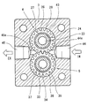
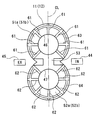
- FIG. 2 is a cross-sectional view taken along line II-II in FIG. It is the front view which showed the contact surface of the side plate based on 1st Embodiment. It is the graph which showed the relationship of the amount of fuel leaks and groove area / contact part total area based on 1st Embodiment. It is explanatory drawing which showed the contact surface of the side plate based on the comparative example of 1st Embodiment. It is the front view which showed the contact surface of the side plate based on 2nd Embodiment.
- the fuel supply device of the present embodiment is a dimethyl ether fuel (hereinafter referred to as dimethyl ether fuel) mainly composed of dimethyl ether having a viscosity lower than that of light oil and containing a component that vaporizes under atmospheric pressure as a fuel for a traveling engine mounted on an automobile. , Called DME fuel).
- DME fuel is a liquid fuel having a kinematic viscosity at 25 ° C. of 0.27 cst.
- the fuel supply device includes a low pressure fuel pump, a high pressure fuel pump (not shown), a common rail (not shown), and a plurality of fuel injection valves (not shown).
- an external gear type fuel pump is used as the low-pressure fuel pump.
- the external gear type fuel pump is referred to as a low pressure fuel pump 1.
- the low-pressure fuel pump 1 sucks DME fuel from a fuel tank (not shown) and raises the pressure.
- the high pressure fuel pump pressurizes the DME fuel sent from the low pressure fuel pump 1.
- DME fuel is introduced into the common rail from a high-pressure fuel pump. DME fuel is distributed and supplied from the common rail to the plurality of fuel injection valves.
- the high-pressure fuel pump has a known configuration, pressurizes and pressurizes the DME fuel sucked into the pressurizing chamber by reciprocating the plunger in the cylinder, and discharges it to the engine side.
- the common rail has a known configuration and has a pressure accumulating chamber for accumulating DME fuel.
- the plurality of fuel injection valves have a known configuration, and inject the DME fuel accumulated in the pressure accumulation chamber into the cylinder of the engine.
- the low-pressure fuel pump 1 is installed in a fuel tank. However, the low-pressure fuel pump 1 may be installed outside the fuel tank.
- the low-pressure fuel pump 1 increases the pressure of the sucked DME fuel and feeds it toward the high-pressure fuel pump.
- the low-pressure fuel pump 1 includes an electric motor 2 and a pair of gears.
- the electric motor 2 is energized and controlled by an electronic control unit (hereinafter referred to as ECU).
- the pair of gears includes a drive gear 4 and a driven gear 5, and is rotationally driven by the drive shaft 3 of the electric motor 2.
- the low-pressure fuel pump 1 includes the drive gear 4 (first gear) and the driven gear 5 (second gear) that are arranged in pairs and are driven by the drive shaft 3 to mesh with each other and rotate.
- the low-pressure fuel pump 1 includes a pump case 7, a pair of side plates (first side plate 11 and second side plate 12), and screws 13 and 14.
- the pump case 7 is attached to the bracket 6 of the electric motor 2.
- the pair of side plates are disposed on both sides of the drive gear 4 in the axial direction of the drive shaft 3 (rotation axis RL1 direction) and on both sides of the driven gear 5 in the axial direction (rotation axis RL2 direction). That is, the pair of side plates has the first side plate 11 and the second side plate 12 that are respectively disposed on both sides of the drive gear 4 and the driven gear 5 in the axial direction of the drive shaft 3.
- the screw 13 is a screw for adjusting a gap for eliminating a gap between the drive gear 4 and the pair of side plates.
- the screw 14 is a gap adjusting screw for eliminating a gap between the driven gear 5 and the pair of side plates.
- the electric motor 2 When the electric motor 2 is supplied with electric power, the electric motor 2 generates rotational power for rotating the drive gear 4.
- the electric motor 2 is electrically connected to a battery (not shown) via a motor drive circuit electronically controlled by the ECU.
- the drive gear 4 is made of metal.
- the drive gear 4 rotates in a predetermined rotation direction about the rotation axis RL1 shown in FIG.
- the drive gear 4 is fixed to the outer periphery on the tip side of the drive shaft 3 via a key 15.
- the drive gear 4 is connected to the drive shaft 3 so as to be integrally rotatable.
- Two gear side surfaces 21 and 22 that can rotate and slide with respect to the first side plate 11 and the second side plate 12 are formed on both sides of the drive gear 4 in the axial direction.
- the two gear side surfaces 21 and 22 face each other in the axial direction of the drive shaft 3.
- the drive gear 4 has a cylindrical sleeve 24 and an annular tooth forming portion 25.
- a through hole 23 extending in the axial direction is formed inside the sleeve 24.
- the tooth forming portion 25 protrudes radially outward from the outer peripheral surface of the sleeve 24.
- the tip side of the drive shaft 3 is inserted into the sleeve 24.
- the sleeve 24 is rotatably supported on the motor side of the tooth forming portion 25 via a bearing 26.
- the sleeve 24 is rotatably supported on the opposite side to the motor side of the tooth forming portion 25 via a bearing 27.
- a plurality of gear tooth portions 28 that mesh with the driven gear 5 in the entire circumferential direction are provided on the outer periphery of the tooth forming portion 25.
- the driven gear 5 is made of metal.
- the driven gear 5 rotates in a predetermined rotation direction about the rotation axis RL2 shown in FIG.
- two gear side surfaces 31 and 32 are formed that can rotate and slide with respect to the first side plate 11 and the second side plate 12, respectively.
- the two gear side surfaces 31 and 32 face each other in the axial direction of the drive shaft 3.
- the driven gear 5 includes a cylindrical sleeve 34 in which a through hole 33 extending in the axial direction is formed, and an annular tooth forming portion 35 that protrudes radially outward from the outer peripheral surface of the sleeve 34.
- the sleeve 34 has a hollow inside.
- the sleeve 34 is rotatably supported at a motor side portion of the tooth forming portion 35 via a bearing 36.
- the sleeve 34 is rotatably supported at a portion opposite to the motor side of the tooth forming portion 35 via a bearing 37.
- On the outer periphery of the tooth forming portion 35 a plurality of gear tooth portions 38 that mesh with the plurality of gear tooth portions 28 are provided in the entire circumferential direction.
- the bracket 6 is integrally attached to the front side of the electric motor 2.
- the bracket 6 fastens and fixes a flange (not shown) of the pump case 7 using a plurality of screws (not shown). Further, a coupling end surface for coupling the pump case 7 is formed on the pump side end surface of the bracket 6.
- the bracket 6 is formed with a bearing hole 41 through which the drive shaft 3 slides rotatably.
- the pump case 7 forms a pump chamber 42 between the end face of the bracket 6 on the pump side.
- the drive gear 4 and the driven gear 5 are rotatably accommodated.
- the first side plate 11 and the second side plate 12 are accommodated in the pump chamber 42.
- the first side plate 11 and the second side plate 12 are made of metal.
- a gear chamber 43 that accommodates the drive gear 4 and the driven gear 5 is formed between the first side plate 11 and the second side plate 12.
- the first side plate 11 and the second side plate 12 are disposed to face each other with the gear chamber 43 therebetween.
- the pump chamber 42 has a suction side space 44 and a discharge side space 45 of the low pressure fuel pump 1.
- DME fuel is sucked into the suction side space 44 from the fuel tank via a suction passage (not shown) formed in the pump case 7.
- the suction side space 44 communicates with the gear chamber 43 through the fuel suction passage 44a.
- DME fuel supplied to the high-pressure fuel pump is introduced into the discharge side space 45 via a discharge passage (not shown) formed in the pump case 7.
- the discharge side space 45 communicates with the gear chamber 43 through the fuel discharge passage 45a.
- the DME fuel that moves on the outer peripheral side of the drive gear 4 and the DME fuel that moves on the outer peripheral side of the driven gear 5 reach the discharge side of the pump chamber 42 and merge.
- the DME fuel on the suction side of the pump chamber 42 is formed between the tooth surfaces of the plurality of gear tooth portions 28 and the inner peripheral surface of the gear chamber 43 when the drive gear 4 rotates about the rotation shaft RL1. Inhaled between.
- the DME fuel moves on the outer peripheral side of the drive gear 4 in the gear rotation direction and reaches the discharge side of the pump chamber 42.
- the driven gear 5 rotates about the rotation axis RL 2
- the DME fuel on the suction side of the pump chamber 42 is sucked between the tooth surfaces of the plurality of gear tooth portions 38 and the inner peripheral surface of the gear chamber 43.
- the DME fuel moves on the outer peripheral side of the driven gear 5 in the gear rotation direction and reaches the discharge side of the pump chamber 42.
- the DME fuel from the outer peripheral side of the drive gear 4 and the DME fuel from the outer peripheral side of the driven gear 5 merge on the discharge side of the pump chamber 42 and reach the discharge side space 45 through the fuel discharge passage 45a.
- the DME fuel that has reached the discharge side space 45 is supplied from the low pressure fuel pump 1 to the high pressure fuel pump.
- the first side plate 11 and the second side plate 12 have a bearing hole 46 and a bearing hole 47, respectively.
- the bearing hole 46 supports the outer peripheral surface of the sleeve 24 via the bearings 26 and 27.
- the bearing hole 47 supports the outer peripheral surface of the sleeve 34 via the bearings 36 and 37.
- the first side plate 11 has plate contact surfaces 51a, 52a, 53 (contact surfaces) that are in sliding contact with the drive gear 4 and the driven gear 5.
- the second side plate 12 has plate contact surfaces 51 b, 52 b, 53 that are in sliding contact with the drive gear 4 and the driven gear 5.
- the first side plate 11 has two plate contact surfaces 51a and 52a (two contact surfaces).
- the plate contact surface 51 a is in sliding contact with one gear side surface 21 of the two gear side surfaces 21 and 22 of the drive gear 4.
- the plate contact surface 52 a is in sliding contact with one gear side surface 31 of the two gear side surfaces 31 and 32 of the driven gear 5.
- the second side plate 12 has two plate contact surfaces 51b and 52b (two contact surfaces).
- the plate contact surface 51 b is in sliding contact with the other gear side surface 22 of the two gear side surfaces 21, 22 of the drive gear 4.
- the plate contact surface 52 b is in sliding contact with the other gear side surface 32 of the two gear side surfaces 31 and 32 of the driven gear 5.
- the plate contact surfaces 51a and 51b are in sliding contact with the gear side surfaces 31 and 32 of the drive gear 4, respectively.
- the plate contact surface 51 is formed in an annular shape so as to surround the bearing hole 46 in the circumferential direction. In other words, the bearing hole 46 opens at the plate contact surface 51.
- the plate contact surfaces 52a and 52b are in sliding contact with the gear side surfaces 31 and 32 of the driven gear 5, respectively.
- the plate contact surface 52 is formed in an annular shape so as to surround the bearing hole 47 in the circumferential direction. In other words, the bearing hole 47 opens at the plate contact surface 52.
- the plate contact surface 53 is formed on both side surfaces in the axial direction of the plurality of gear tooth portions 28 and in the axial direction of the plurality of gear tooth portions 38 at meshing portions of the plurality of gear tooth portions 28 and the plurality of gear tooth portions 38. Makes sliding contact with both sides.
- the plate contact surface 53 connects the plate contact surface 51a and the plate contact surface 52a.
- the plate contact surface 53 connects the plate contact surface 51b and the plate contact surface 52b.
- the major axis CL direction of the first side plate 11 and the second side plate 12 is the longitudinal direction (up and down direction in FIG. 3), and the direction perpendicular to the longitudinal direction is the transverse direction (FIG. 3).
- the plate contact surface 51 is disposed above the plate contact surface 53, and the plate contact surface 52 is disposed below the plate contact surface 53.
- the right side of the long axis CL of the first side plate 11 and the second side plate 12 is the suction side of the pump chamber 42 and the gear chamber 43
- the left side of the long axis CL is It becomes the discharge side of the pump chamber 42 and the gear chamber 43.
- the plate contact surfaces 51 a and 51 b are formed with a plurality of oil grooves 61 and 63 that communicate the discharge side space 45 of the pump chamber 42 and the suction side space 44 of the pump chamber 42, respectively.
- a plurality of oil grooves 62 and 64 communicating with the discharge side space 45 of the pump chamber 42 and the suction side space 44 of the pump chamber 42 are formed in the plate contact surfaces 52a and 52b, respectively.
- the plurality of oil grooves 61 to 64 include a contact portion between the two gear side surfaces 21 and 22 of the drive gear 4 and the plate contact surfaces 51a and 51b, and two gear side surfaces 31 and 32 of the driven gear 5 and the plate contact surface 52a, A part of the DME fuel is supplied to the contact portion with 52b.
- the plurality of oil grooves 61 are a plurality of radial oil grooves provided in each of the plate contact surfaces 51a and 51b and extending in the radial direction.
- the plurality of oil grooves 61 extend radially around the bearing hole 46.
- the plurality of oil grooves 62 are a plurality of radial oil grooves provided in each of the plate contact surfaces 52a and 52b and extending in the radial direction.
- the plurality of oil grooves 62 extend radially around the bearing hole 47.
- the oil groove 63 is a circumferential oil groove provided so as to extend in the circumferential direction on the radially outer side of the plate contact surfaces 51a and 51b.
- the oil groove 63 intersects each of the plurality of oil grooves 61 so as to connect the plurality of oil grooves 61.
- the oil groove 64 is a circumferential oil groove provided to extend in the circumferential direction on the radially outer side of the plate contact surfaces 52a and 52b.
- the oil groove 64 intersects each of the plurality of oil grooves 62 so as to connect the plurality of oil grooves 62.
- the groove width and groove depth of the plurality of oil grooves 61 and 62 are constant over the entire length in the radial direction.
- the groove width and groove depth of the oil grooves 63 and 64 are constant over the entire circumferential length of each plate contact surface 51a, 51b, 52a, 52b.
- the groove depth of the plurality of oil grooves 61 to 64 is h, they are provided so as to satisfy the relationship of 5 ⁇ m ⁇ h ⁇ 10 ⁇ m.
- each of the plurality of oil grooves 61 to 64 is less than 5 ⁇ m, the contact portion between the gear side surface 21 and the plate contact surface 51a, the contact portion between the gear side surface 22 and the plate contact surface 51b, and the gear DME fuel hardly flows through the contact portion between the side surface 31 and the plate contact surface 52a and the contact portion between the gear side surface 32 and the plate contact surface 52b. As a result, a decrease in pump efficiency can be suppressed, but the lubricity at the contact portion tends to decrease.
- each of the plurality of oil grooves 61 to 64 is deeper than 10 ⁇ m, a large amount of DME fuel is transferred from the discharge side space 45 to the suction side space 44 via the plurality of oil grooves 61 to 64.
- the lubricity at the contact portion can be ensured, but the pump efficiency tends to decrease.
- equation (1) shows an arithmetic expression showing the relationship between the fuel leak amount Q leaking from the discharge side space 45 to the suction side space 44 and the groove depth h.
- ⁇ is the kinematic viscosity of the liquid fuel
- L is the linear distance between the discharge side space 45 and the suction side space 44
- b is the groove width of the plurality of oil grooves 61 to 64
- h is the groove depth of the plurality of oil grooves 61 to 64. It is.
- ⁇ P is a pressure difference between the fuel pressure in the suction side space 44 and the fuel pressure in the discharge side space 45.
- the contact portions between the gear side surfaces 21 and 22 and the plate contact surfaces 51a and 51b, and the contact portions between the gear side surfaces 31 and 32 and the plate contact surfaces 52a and 52b are provided so as to extend in the radial direction so that they do not contact each other over the entire circumference in the circumferential direction. Furthermore, oil grooves 63 and 64 that cross the plurality of oil grooves 61 and 62 and connect the plurality of oil grooves 61 and 62 in the circumferential direction are provided so as to extend in the circumferential direction so that the DME fuel spreads over the entire surface. Yes.
- the discharge side space 45 and the suction side space 44 communicate with each other through the bearing holes 46 and 47 through the plurality of oil grooves 61 to 64, so that the flow of DME fuel into the plurality of oil grooves 61 to 64 is achieved. Is always formed. Thereby, the contact portion between the gear side surface 21 and the plate contact surface 51a, the contact portion between the gear side surface 22 and the plate contact surface 51b, the contact portion between the gear side surface 31 and the plate contact surface 52a, and the gear side surface 32 and the plate contact surface. Even when the DME fuel in the plurality of oil grooves 61 to 64 is locally vaporized due to local sliding resistance at the contact portion with 52b, the vaporized fuel is promptly transferred to the suction side space 44. Can be discharged.
- Patent Document 1 oil grooves for ensuring slidability between the gear side surfaces of the pair of gears and the plate contact surfaces of the pair of side plates are provided on the discharge side space and the suction side space of the fuel pump. A configuration that does not communicate with is also disclosed.
- a plurality of oil grooves 61 to 64 that connect the discharge side space 45 and the suction side space 44 are provided for the purpose of lubricating the contact portion.
- the DME fuel in a liquid state always flows through .about.64. Thereby, the lubricity in a contact part can be improved.
- the groove depth h of the oil grooves 61 to 64 is made extremely shallow, such as 10 ⁇ m or less. Desirably, by setting the groove depth h to 5 to 10 ⁇ m, the amount of DME fuel flowing out from the discharge side space 45 to the suction side space 44 through the oil grooves 61 to 64 is minimized. Thereby, the fall of pump efficiency can be suppressed.
- FIG. 4 shows the result of this experiment, and is a graph showing the relationship between the amount of fuel leak and the groove area / total contact area.
- FIG. 5 is an explanatory diagram of the plate contact surface of the side plate according to the comparative example in this experiment.
- 5A is a front view showing the plate contact surface of the side plate according to the first condition (condition j1) of the comparative example
- FIG. 5B is a cross-sectional view of FIG. is there.
- FIG. 5C is a front view showing the plate contact surface of the side plate according to the second condition (condition j2) of the comparative example
- FIG. 5D is a cross-sectional view of FIG. is there.
- the groove width b of the plurality of oil grooves 65 and 66 is 0.8 mm, and the groove depth h (clearance). Is 15 ⁇ m.
- the groove width b of the plurality of oil grooves 65 and 66 is 1.7 mm, and the groove depth h (clearance). Is 15 ⁇ m.
- the groove width b of the plurality of oil grooves 65 and 66 is 0.8 mm, and the groove depth h (clearance) is 8 ⁇ m.
- the groove width b of the plurality of oil grooves 65 and 66 is 1.7 mm, and the groove depth h (clearance) is 8 ⁇ m.
- the groove area is The amount of fuel leak decreases as it decreases.
- the amount of fuel leakage is larger than the target value that can suppress the decrease in pump efficiency even when the groove area / total contact area is changed to the condition j1.
- the amount of fuel leakage in the condition J1 is smaller than the target value that can suppress the decrease in pump efficiency.
- the fuel leak amount Q decreases in inverse proportion to the cube of the groove depth h of the plurality of oil grooves 61 to 64 as shown in the above formula (1). That is, the smaller the groove depth h, the smaller the fuel leak amount Q.
- the discharge side space 45 and the suction side space 44 are communicated with each other by the plurality of oil grooves 61 to 64 through the bearing holes 46 and 47, and the groove depth h of the plurality of oil grooves 61 to 64 is 5 ⁇ m or more. And by setting it as 10 micrometers or less, even when it is a case where DME fuel is used as lubricating oil, coexistence with ensuring of the lubricity in a contact part and suppression of a pump efficiency fall can be aimed at.
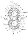
- a plurality of oil grooves 71 and 73 are formed on the plate contact surfaces 51a and 51b of the present embodiment, respectively.
- the plurality of oil grooves 71 and 73 supply a part of the DME fuel to the contact portion between the gear side surface 21 and the plate contact surface 51a and the contact portion between the gear side surface 22 and the plate contact surface 51b.
- a plurality of oil grooves 72 and 74 are formed in the plate contact surfaces 52a and 52b, respectively.
- the plurality of oil grooves 72 and 74 supply a part of the DME fuel to the contact portion between the gear side surface 31 and the plate contact surface 52a and the contact portion between the gear side surface 32 and the plate contact surface 52b.
- the major axis CL direction of the first side plate 11 and the second side plate 12 is the longitudinal direction (up and down direction in FIG. 6), and the minor axis direction perpendicular to the longitudinal direction is the short direction (left and right direction in FIG. 6).
- the plurality of oil grooves 71 to 74 are a plurality of oil grooves 71 and 72 that are a plurality of vertical grooves extending in the longitudinal direction, and a plurality of oil grooves 73 and 74 that are a plurality of vertical grooves extending in the short direction. It has.
- the plurality of oil grooves 71 vertically intersect with the plurality of oil grooves 73 so as to connect the plurality of oil grooves 73 to each other on each of the plate contact surfaces 51a and 51b.
- the plurality of oil grooves 72 vertically intersect with the plurality of oil grooves 74 so as to connect the plurality of oil grooves 74 to each other on each of the plate contact surfaces 52a and 52b.
- the low-pressure fuel pump 1 of the present embodiment has the same effect as that of the first embodiment.
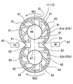
- a plurality of oil grooves 81 and 83 are formed in each of the plate contact surfaces 51a and 51b of the present embodiment.
- the plurality of oil grooves 81 and 83 supply a part of the DME fuel to the contact portion between the gear side surface 21 and the plate contact surface 51a and the contact portion between the gear side surface 22 and the plate contact surface 51b.
- a plurality of oil grooves 82 and 84 are formed on the plate contact surfaces 52a and 52b, respectively.
- the plurality of oil grooves 82 and 84 supply a part of the DME fuel to the contact portion between the gear side surface 31 and the plate contact surface 51a and the contact portion between the gear side surface 32 and the plate contact surface 52b.
- the plurality of oil grooves 81 are radial oil grooves extending in the radial direction on each of the plate contact surfaces 51a and 51b.
- the plurality of oil grooves 81 are inclined by a predetermined angle toward the gear rotation direction indicated by the arrow RD1 in FIG. 7 with respect to the radial direction.
- the plurality of oil grooves 82 are radial oil grooves extending in the radial direction on each of the plate contact surfaces 52a and 52b.
- the plurality of oil grooves 82 are inclined by a predetermined angle in the gear rotation direction indicated by the arrow RD2 in FIG. 7 with respect to the radial direction.
- the oil groove 83 is a circumferential oil groove provided so as to extend in the circumferential direction on the radially outer side of the plate contact surfaces 51a and 51b.
- the oil groove 83 intersects each of the plurality of oil grooves 81 so as to connect the plurality of oil grooves 81 to each other.
- the oil groove 84 is a circumferential oil groove provided so as to extend in the circumferential direction on the radially outer side of each of the plate contact surfaces 52a and 52b.
- the oil groove 84 intersects each of the plurality of oil grooves 82 so as to connect the non-empty oil grooves 82 to each other.
- the low-pressure fuel pump 1 of the present embodiment has the same effects as those of the first and second embodiments.
- a plurality of oil grooves 85 and 87 are formed in the plate contact surfaces 51a and 51b of the present embodiment, respectively.
- the plurality of oil grooves 85 and 87 respectively supply part of the DME fuel to the contact portion between the gear side surface 21 and the plate contact surface 51a and the contact portion between the gear side surface 22 and the plate contact surface 51b.
- a plurality of oil grooves 86 and 88 are formed in the plate contact surfaces 52a and 52b, respectively.
- the plurality of oil grooves 86 and 88 supply a part of the DME fuel to the contact portion between the gear side surface 31 and the plate contact surface 52a and the contact portion between the gear side surface 32 and the plate contact surface 52b.
- the plurality of oil grooves 85 are radial oil grooves extending in the radial direction.
- the plurality of oil grooves 85 are inclined in the gear rotation direction indicated by the arrow RD1 in FIG. 8 with respect to the radial direction. Further, the plurality of oil grooves 85 are gradually narrowed from the radially outer side toward the bearing hole 46 side.
- the plurality of oil grooves 86 are radial oil grooves extending in the radial direction.
- the plurality of oil grooves 86 are inclined in the gear rotation direction indicated by the arrow RD2 in FIG. 8 with respect to the radial direction. Further, the plurality of oil grooves 86 have a groove width that gradually decreases from the radially outer side toward the bearing hole 47 side.
- the oil groove 87 is a circumferential oil groove provided so as to extend in the circumferential direction on the radially outer side of the plate contact surfaces 51a and 51b.
- the oil groove 87 intersects each of the plurality of oil grooves 85 so as to connect the plurality of oil grooves 85 to each other.
- the oil groove 88 is a circumferential oil groove provided to extend in the circumferential direction on the radially outer side of each of the plate contact surfaces 52a and 52b.
- the oil groove 88 intersects each of the plurality of oil grooves 85 so as to connect the plurality of oil grooves 85 to each other.
- the groove widths of the plurality of oil grooves 85, 86 are set like the oil grooves 81, 82 of FIG. 7. If it is constant in the radial direction, the DME fuel is likely to stay on the radially outer peripheral side of the plurality of oil grooves 85 and 86. For this reason, in the plurality of oil grooves 85, 86, the width on the outer circumferential side in the radial direction is made wider than the groove width on the inner circumferential side in the radial direction, thereby preventing the DME fuel from staying due to the difference in speed. As a result, the DME fuel easily flows from the discharge side space 45 through the oil grooves 85 to 88 toward the suction side space 44.
- the low-pressure fuel pump 1 of the present embodiment has the same effects as those of the first, second, and third embodiments.
- a plurality of oil grooves 91 and 93 are formed on each of the plate contact surfaces 51a and 51b of the present embodiment.
- the plurality of oil grooves 91 and 93 supply a contact portion between the gear side surface 21 and the plate contact surface 51a, a contact portion between the gear side surface 22 and the plate contact surface 51b, and a part of the DME fuel.
- a plurality of oil grooves 92 and 94 are formed in the plate contact surfaces 52a and 52b, respectively.
- the plurality of oil grooves 92 and 94 supply a contact portion between the gear side surface 31 and the plate contact surface 52a, a contact portion between the gear side surface 32 and the plate contact surface 52b, and a part of the DME fuel.
- the plurality of oil grooves 91 are radial oil grooves extending in the radial direction. Further, the plurality of oil grooves 91 are gradually narrowed from the radially outer side toward the bearing hole 46 side.
- the plurality of oil grooves 92 are radial oil grooves extending in the radial direction. Further, the plurality of oil grooves 92 have a groove width that gradually decreases from the radially outer side toward the bearing hole 47 side.
- the oil groove 93 is a circumferential oil groove provided so as to extend in the circumferential direction on the radially outer side of each of the plate contact surfaces 51a and 51b.
- the oil groove 93 intersects each of the plurality of oil grooves 91 so as to connect the plurality of oil grooves 91.
- the oil groove 94 is a circumferential oil groove provided so as to extend in the circumferential direction on the radially outer side of each of the plate contact surfaces 52a and 52b.
- the oil groove 94 intersects each of the plurality of oil grooves 92 so as to connect the plurality of oil grooves 92 to each other.
- the plurality of oil grooves 91 may be referred to as oil grooves 91 a to 91 g in order from the oil groove 91 on the discharge side closest to the discharge side space 45 to the oil groove 91 on the suction side closest to the suction side space 44. is there.
- the plurality of oil grooves 92 may be referred to as oil grooves 92 a to 92 g in order from the discharge-side oil groove 92 closest to the discharge-side space 45 to the suction-side oil groove 92 closest to the suction-side space 44. .
- DME fuel leaks from the discharge-side space 45 having a relatively high pressure to the suction-side space 44 having a relatively low pressure.
- DME fuel flows from the oil grooves 91a and 92a on the discharge side.
- the DME fuel flowing in from the oil grooves 91a and 92a passes through the oil grooves 93 and 94, the oil grooves 91b and 92b, and the oil grooves 91c and 92c as shown by an arrow F in FIG. It flows out from 92g.
- the plurality of oil grooves 91 have a groove shape in which the groove width gradually decreases from the radially outer side toward the radially inner side.
- the plurality of oil grooves 92 have a groove shape in which the groove width gradually decreases from the radially outer side toward the radially inner side.
- a plurality of such groove-shaped oil grooves 91 and 92 form a lubricating flow path through which sufficient DME fuel flows at the inlets of the oil grooves 91a and 92a. Since the groove widths of the oil grooves 91a and 92a gradually become narrower toward the bearing holes 46 and 47, the amount of DME fuel flowing through the oil grooves 91a and 92a is reduced as compared with the case where the groove width and the groove depth are constant. It becomes possible.
- DME fuel can be supplied to the other oil grooves 91b to 91f and 92b to 92f as a lubricating oil, the entire oil grooves 91 and 93 formed on the plate contact surfaces 51a and 51b, DME fuel can be supplied to the entire oil grooves 92 and 94 formed on the plate contact surfaces 52a and 52b.
- the low-pressure fuel pump 1 of the present embodiment has the same effects as those of the first, second, third, and fourth embodiments.
- the groove widths of the oil grooves 91 and 92 of the present embodiment are gradually narrowed from the radially outer side toward the radially inner side.
- the groove depths of the oil grooves 91 and 92 may be made shallower in the radial direction, that is, toward the bearing holes 46 and 47. Even in this case, the same effect as the present embodiment can be obtained.
- a DME fuel having a kinematic viscosity of 0.27 cst at 25 ° C. is used as a liquid fuel having a viscosity lower than that of light oil.
- a liquid fuel having a kinematic viscosity at 25 ° C. higher than 0.27 cst may be used as a liquid fuel having a viscosity lower than that of light oil.
- a liquid fuel having a kinematic viscosity at 25 ° C. of 1 cst or less is used.
- any liquid fuel of propane, isobutane, butane, butene, or propylene may be used.
- a mixed fuel obtained by mixing any two of DME, propane, isobutane, butane, butene, and propylene may be used as the fuel used.
- the fuel used may be a mixed fuel obtained by mixing any one or more of propane, isobutane, butane, butene, and propylene with light oil at an arbitrary ratio.
- the fuel used may be a high-concentration DME mixed fuel obtained by mixing DME and light oil at an arbitrary ratio, or a DME 100% fuel. Further, the fuel used may be LPG or gasoline oil.
- the low-pressure fuel pump 1 that boosts the liquid fuel sucked from the fuel tank and feeds the fuel toward the high-pressure fuel pump is employed as the fuel pump of the present disclosure.
- a fuel pump that boosts the liquid fuel sucked from the fuel tank and feeds the fuel toward the engine may be employed as the fuel pump of the present disclosure.
- a fuel pump that feeds liquid fuel toward the fuel injection valve may be employed.
- a plurality of oil grooves 61 to 64, 71 to 74, 81 to 88, and 91 to 94 are provided on the plate contact surfaces 51a, 51b, 52a, and 52b of the pair of side plates.
- a plurality of oil grooves 61 to 64, 71 to 74, 81 to 88, and 91 to 94 may be provided on the gear side surfaces 21 and 22 of the drive gear 4 and the gear side surfaces 31 and 32 of the driven gear 5.
- the first side plate 11 is pressed against the gear side surface 21 of the drive gear 4 and the gear side surface 31 of the driven gear 5, and the second side plate 12 is pressed against the drive gear 4.
- An elastic member such as a spring that generates a biasing force may be provided so as to press against each of the gear side surface 22 and the gear side surface 32 of the driven gear 5.
Landscapes
- Engineering & Computer Science (AREA)
- Mechanical Engineering (AREA)
- General Engineering & Computer Science (AREA)
- Chemical & Material Sciences (AREA)
- Combustion & Propulsion (AREA)
- Rotary Pumps (AREA)
- Details And Applications Of Rotary Liquid Pumps (AREA)
Abstract
外接歯車式の燃料ポンプは、軽油よりも低粘度の燃料を吸入して昇圧し、エンジン側へ吐出する。燃料ポンプは、一対のギヤ(4、5)と、一対のギヤの回転軸(RL1、RL2)方向の両側に配置される一対のサイドプレート(11、12)と、を備える。一対のギヤは、回転軸方向の両側に形成されるギヤ側面(21、22、31、32)をそれぞれ有している。一対のサイドプレートは、各ギヤ側面が回転摺動可能に接触する接触面(51a、51b、52a、52b)をそれぞれ有している。各ギヤ側面または各接触面のうちのいずれか一方には、燃料ポンプにおける吐出側空間(45)と吸入側空間(44)とを連通して低粘度の燃料の一部を一対のギヤと一対のサイドプレートとの接触部に供給する複数の油溝(61~66、71~74、81~88、91~94)が形成されている。複数の油溝それぞれの溝深さをhとした場合、5μm≦h≦10μmの関係が満たされる。
Description
本出願は、当該開示内容が参照によって本出願に組み込まれた、2015年10月29日に出願された日本特許出願2015-213416号を基にしている。
本開示は、軽油よりも低粘度の燃料を吸入して昇圧し、エンジン側へ送油する外接歯車式の燃料ポンプに関するものである。
燃料タンクから吸入した燃料を昇圧し、エンジン側へ送油する外接歯車式の燃料ポンプが提案されている(例えば、特許文献1参照)。
燃料ポンプは、互いに噛み合って回転する一対のギヤと、一対のギヤの回転軸方向の両側に設置された一対のサイドプレートと、一対のサイドプレート間に形成されるギヤ室とを備えている。
ギヤ室には、燃料ポンプにおける吐出側の空間と、燃料ポンプにおける吸入側の空間とが形成されている。また、ギヤ室内には、一対のギヤが回転可能に収容されている。
そして、少なくとも一方のサイドプレートは、弾性部材によって軸方向両側から一対のギヤの各側面に押し付けられている。これにより、一対のサイドプレートの各接触面に一対のギヤの各側面が回転摺動する。
ここで、特許文献1には、サイドプレートの接触面に、吐出側の空間と吸入側の空間とを連通する油溝を設けた燃料ポンプが開示されている。燃料ポンプは、吐出側の空間から吸入側の空間へ向けて燃料を流し、一対のギヤと一対のサイドプレートとの接触部における潤滑性を高めるように構成されている。
ところが、軽油よりも粘度が低いDME燃料を潤滑油として使用した場合には、吐出側の空間から吸入側の空間へリークするDME燃料が軽油よりも増加する。このため、燃料ポンプでDME燃料を昇圧する昇圧効率が低下するので、ポンプ効率が低下するという問題がある。
したがって、DME燃料を潤滑油として使用する場合には、接触部における潤滑性を高めるとともに、ポンプ効率の低下を抑えることが可能な外接歯車式の燃料ポンプが要望される。
上記点に鑑み、本開示は、軽油よりも粘度が低い燃料を潤滑油として使用する場合であっても、接触部における潤滑性を高めるとともに、ポンプ効率の低下を抑えることのできる外接歯車式の燃料ポンプを提供することを目的とする。
本開示の第1態様に係る外接歯車式の燃料ポンプは、軽油よりも低粘度の燃料を吸入して昇圧し、エンジン側へ吐出する。
外接歯車式の燃料ポンプは、互いに噛み合って回転する一対のギヤと、一対のギヤの回転軸方向の両側に配置される一対のサイドプレートと、を備える。一対のギヤは、その回転軸方向の両側に形成されるギヤ側面をそれぞれ有している。一対のサイドプレートは、一対のギヤの各ギヤ側面が回転摺動可能に接触する接触面をそれぞれ有している。一対のギヤの各ギヤ側面または一対のサイドプレートの各接触面のうちのいずれか一方には、燃料ポンプにおける吐出側空間と燃料ポンプにおける吸入側空間とを連通して低粘度の燃料の一部を一対のギヤと一対のサイドプレートとの接触部に供給する複数の油溝が形成されている。複数の油溝それぞれの溝深さをhとした場合、5μm≦h≦10μmの関係が満たされる。
ここで、複数の油溝における各溝深さが5μmよりも小さいと、吐出側空間から吸入側空間へリークする低粘度の燃料量が少なく、接触部における潤滑性を維持することができない。複数の油溝における各溝深さが10μmよりも大きいと、油溝を流れる低粘度の燃料量が多くポンプ効率を低下させる。したがって、軽油よりも粘度が低い燃料を潤滑油として使用する場合であっても、接触部における潤滑性を高めるとともに、ポンプ効率の低下を抑えることができる。
あるいは、本開示の第2態様に係る外接歯車式の燃料ポンプは、第1ギヤ、第2ギヤ、第1サイドプレート、および第2サイドプレートを有してもよい。
第1ギヤおよび第2ギヤは、駆動軸により駆動されて互いに噛み合って回転する。第1サイドプレートおよび第2サイドプレートは、駆動軸の軸方向において第1ギヤおよび第2ギヤの両側にそれぞれ配置される。第1ギヤは軸方向において対向する2つのギヤ側面を有している。第2ギヤは軸方向において対向する2つのギヤ側面を有している。
第1サイドプレートは、軸方向において対向し、第1ギヤの2つのギヤ側面のうちの一方のギヤ側面および第2ギヤの2つのギヤ側面のうちの一方のギヤ側面とそれぞれ摺接する2つの接触面を有している。第2サイドプレートは、軸方向において対向し、第1ギヤの2つのギヤ側面のうちの他方のギヤ側面および第2ギヤの2つのギヤ側面のうちの他方のギヤ側面とそれぞれ摺接する2つの接触面を有している。
燃料ポンプは、吐出側空間と吸入側空間を有している。第1および第2ギヤのギヤ側面、または第1および第2サイドプレートの接触面のうちのいずれか一方には、複数の油溝が形成されている。複数の油溝は、吐出側空間と吸入側空間とを連通して第1および第2ギヤと第1サイドプレートとの接触部と、第1および第2ギヤと第2サイドプレートとの接触部と、に低粘度の燃料の一部を供給する。複数の油溝の溝深さをhとした場合、5μm≦h≦10μmの関係が満たされている。
第2態様によっても、第1態様と同様の効果を得ることができる。
本開示についての上記目的およびその他の目的、特徴や利点は、添付の図面を参照しながら下記の詳細な記述により、より明確になる。
第1実施形態に係る外接歯車式の燃料ポンプを示した断面図である。
図1のII-II線における断面図である。
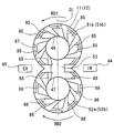
第1実施形態に係る、サイドプレートの接触面を示した正面図である。
第1実施形態に係る、燃料リーク量と溝面積/接触部全面積の関係を示したグラフである。
第1実施形態の比較例に係る、サイドプレートの接触面を示した説明図ある。
第2実施形態に係る、サイドプレートの接触面を示した正面図である。
第3実施形態に係る、サイドプレートの接触面を示した正面図である。
第4実施形態に係る、サイドプレートの接触面を示した正面図である。
第5実施形態に係る、サイドプレートの接触面を示した正面図である。
第5実施形態に係る、燃料の流れを示した説明図である。
以下に、図面を参照しながら本開示を実施するための複数の実施形態を説明する。各実施形態において先行する実施形態で説明した事項に対応する部分には同一の参照符号を付して重複する説明を省略する場合がある。各実施形態において構成の一部のみを説明している場合は、構成の他の部分については先行して説明した実施形態と同様とする。各実施形態で具体的に説明している部分の組合せばかりではなく、特に組合せに支障が生じなければ、実施形態同士を部分的に組み合せることも可能である。
(第1実施形態)
第1実施形態を図1から図5を参照して説明する。
第1実施形態を図1から図5を参照して説明する。
本実施形態の燃料供給装置は、自動車に搭載された走行用エンジンの燃料として、軽油よりも低粘度で、しかも大気圧下で気化する成分が含まれたジメチルエーテルを主成分としたジメチルエーテル燃料(以下、DME燃料と称する)を使用している。DME燃料は、25℃における動粘度が0.27cstの液体燃料である。
燃料供給装置は、低圧燃料ポンプと、高圧燃料ポンプ(図示せず)と、コモンレール(図示せず)と、複数の燃料噴射弁(図示せず)と、を備えている。本実施形態では、低圧燃料ポンプとして外接歯車式の燃料ポンプを使用している。以下、外接歯車式の燃料ポンプを低圧燃料ポンプ1と称する。低圧燃料ポンプ1は、燃料タンク(図示せず)からDME燃料を吸入して昇圧する。高圧燃料ポンプは、低圧燃料ポンプ1から送油されたDME燃料を加圧する。コモンレールには、高圧燃料ポンプからDME燃料が導入される。複数の燃料噴射弁には、コモンレールからDME燃料が分配供給される。
高圧燃料ポンプは、公知の構成を備え、シリンダ内をプランジャが往復移動することによって加圧室に吸入したDME燃料を加圧して高圧化し、エンジン側へ吐出する。コモンレールは、公知の構成を備え、内部にDME燃料を蓄圧する蓄圧室を有している。複数の燃料噴射弁は、公知の構成を備え、蓄圧室に蓄圧されたDME燃料をエンジンの気筒内に噴射する。
第1実施形態では、低圧燃料ポンプ1は、燃料タンク内に設置されている。しかしながら、低圧燃料ポンプ1を燃料タンク外に設置しても良い。低圧燃料ポンプ1は、吸入したDME燃料を昇圧して高圧燃料ポンプに向かって送油する。低圧燃料ポンプ1は、電動モータ2と一対のギヤを備えている。電動モータ2は、電子制御装置(以下、ECUと称する)によって通電制御される。一対のギヤは駆動ギヤ4および従動ギヤ5から構成されて、電動モータ2の駆動軸3によって回転駆動される。換言すれば、低圧燃料ポンプ1は、対を成して配置され、駆動軸3により駆動されて互いに噛み合って回転する駆動ギヤ4(第1ギヤ)および従動ギヤ5(第2ギヤ)を備える。
低圧燃料ポンプ1は、ポンプケース7と、一対のサイドプレート(第1サイドプレート11および第2サイドプレート12)と、スクリュー13、14と、を備えている。
ポンプケース7は、電動モータ2のブラケット6に取り付けられる。一対のサイドプレートは、駆動軸3の軸方向(回転軸RL1方向)における駆動ギヤ4の両側、および当該軸方向(回転軸RL2方向)における従動ギヤ5の両側に配置される。つまり、一対のサイドプレートは、駆動軸3の軸方向において駆動ギヤ4および従動ギヤ5の両側にそれぞれ配置される第1サイドプレート11および第2サイドプレート12を有している。
スクリュー13は、駆動ギヤ4と一対のサイドプレートとの間の隙間をなくすための隙間調整用のスクリューである。スクリュー14は、従動ギヤ5と一対のサイドプレートとの間の隙間をなくすための隙間調整用のスクリューである。
電動モータ2は、電力の供給を受けると、駆動ギヤ4を回転駆動する回転動力を発生する。電動モータ2は、ECUによって電子制御されるモータ駆動回路を介して、バッテリ(図示せず)に電気接続されている。
駆動ギヤ4は、金属によって形成されている。駆動ギヤ4は、図1に示す回転軸RL1を軸に所定の回転方向に回転する。駆動ギヤ4は、駆動軸3の先端側の外周にキー15を介して固定されている。駆動ギヤ4は、駆動軸3と一体回転可能に連結している。
駆動ギヤ4の軸方向の両側には、第1サイドプレート11および第2サイドプレート12に対してそれぞれ回転摺動可能な2つのギヤ側面21、22が形成されている。2つのギヤ側面21、22は、駆動軸3の軸方向において対向している。駆動ギヤ4は、円筒状のスリーブ24および円環状の歯形成部25を有している。スリーブ24の内部には、軸方向に延びる貫通孔23が形成されている。歯形成部25は、スリーブ24の外周面から径方向外側へ突出している。
スリーブ24の内部には、駆動軸3の先端側が挿し込まれている。スリーブ24は、歯形成部25のモータ側が、ベアリング26を介して回転可能に支持されている。また、スリーブ24は、歯形成部25のモータ側に対して反対側が、ベアリング27を介して回転可能に支持されている。歯形成部25の外周には、周方向全体に従動ギヤ5と噛み合う複数のギヤ歯部28が設けられている。
従動ギヤ5は、金属によって形成されている。従動ギヤ5は、図1に示す回転軸RL2を軸に所定の回転方向に回転する。従動ギヤ5の軸方向の両側には、第1サイドプレート11および第2サイドプレート12に対してそれぞれ回転摺動可能な2つのギヤ側面31、32が形成されている。2つのギヤ側面31、32は、駆動軸3の軸方向において対向している。従動ギヤ5は、内部に軸方向に延びる貫通孔33が形成された円筒状のスリーブ34、およびスリーブ34の外周面から径方向外側へ突出する円環状の歯形成部35を有している。
スリーブ34は、内部に空洞を有している。スリーブ34は、歯形成部35のモータ側の部位が、ベアリング36を介して回転可能に支持されている。また、スリーブ34は、歯形成部35のモータ側に対して反対側の部位が、ベアリング37を介して回転可能に支持されている。歯形成部35の外周には、周方向全体に複数のギヤ歯部28と噛み合う複数のギヤ歯部38が設けられている。
ブラケット6は、電動モータ2のフロント側に一体的に取り付けられている。ブラケット6は、複数のスクリュー(図示せず)を用いてポンプケース7のフランジ(図示せず)を締結固定している。また、ブラケット6のポンプ側端面には、ポンプケース7を結合する結合端面が形成されている。また、ブラケット6には、駆動軸3が回転可能に摺動する軸受孔41が形成されている。
ポンプケース7は、ブラケット6のポンプ側端面との間にポンプ室42を形成している。ポンプ室42内には、駆動ギヤ4および従動ギヤ5を回転可能に収容している。また、ポンプ室42内には、第1サイドプレート11および第2サイドプレート12が収容されている。
第1サイドプレート11および第2サイドプレート12は、金属によって形成されている。第1サイドプレート11と第2サイドプレート12との間には、駆動ギヤ4および従動ギヤ5を収容するギヤ室43が形成されている。第1サイドプレート11と第2サイドプレート12は、ギヤ室43を隔てて対向して配置されている。
図1および図2に示すように、ポンプ室42は、低圧燃料ポンプ1の吸入側空間44および吐出側空間45を有している。吸入側空間44には、ポンプケース7に形成される吸入通路(図示せず)を介して、燃料タンクからDME燃料が吸入される。吸入側空間44は、燃料吸入通路44aを介してギヤ室43と連通している。吐出側空間45には、ポンプケース7に形成される吐出通路(図示せず)を介して、高圧燃料ポンプへ供給されるDME燃料が導入される。吐出側空間45は、燃料吐出通路45aを介してギヤ室43と連通している。
ここで、吸入側空間44から燃料吸入通路44aを通ってポンプ室42の吸入側に到達したDME燃料は、駆動ギヤ4の外周側を移動するDME燃料と従動ギヤ5の外周側を移動するDME燃料とに別れる。駆動ギヤ4の外周側を移動するDME燃料と従動ギヤ5の外周側を移動するDME燃料は、ポンプ室42の吐出側に到達して合流する。
より具体的には、ポンプ室42の吸入側のDME燃料は、駆動ギヤ4が回転軸RL1を軸に回転すると、複数のギヤ歯部28の各歯面とギヤ室43の内周面との間に吸入される。当該DME燃料は、駆動ギヤ4の外周側をギヤ回転方向に移動してポンプ室42の吐出側に到達する。一方、従動ギヤ5が回転軸RL2を軸に回転すると、ポンプ室42の吸入側のDME燃料は、複数のギヤ歯部38の各歯面とギヤ室43の内周面との間に吸入される。当該DME燃料は、従動ギヤ5の外周側をギヤ回転方向に移動してポンプ室42の吐出側に到達する。
駆動ギヤ4の外周側からのDME燃料と従動ギヤ5の外周側からのDME燃料は、ポンプ室42の吐出側にて合流し、燃料吐出通路45aを通って吐出側空間45に到達する。吐出側空間45に到達したDME燃料は、低圧燃料ポンプ1から高圧燃料ポンプへ供給される。
第1サイドプレート11および第2サイドプレート12はそれぞれ、軸受孔46および軸受孔47を有している。軸受孔46は、ベアリング26、27を介してスリーブ24の外周面を軸受する。軸受孔47は、ベアリング36、37を介してスリーブ34の外周面を軸受する。
第1サイドプレート11は、駆動ギヤ4および従動ギヤ5と摺動接触するプレート接触面51a,52a,53(接触面)を有している。第2サイドプレート12は、駆動ギヤ4および従動ギヤ5と摺動接触するプレート接触面51b,52b,53を有している。
具体的には、第1サイドプレート11は、2つのプレート接触面51a、52a(2つの接触面)を有している。プレート接触面51aは、駆動ギヤ4の2つのギヤ側面21、22のうちの一方のギヤ側面21と摺接する。プレート接触面52aは、従動ギヤ5の2つのギヤ側面31、32のうちの一方のギヤ側面31と摺接する。第2サイドプレート12は、2つのプレート接触面51b、52b(2つの接触面)を有している。プレート接触面51bは、駆動ギヤ4の2つのギヤ側面21、22のうちの他方のギヤ側面22と摺接する。プレート接触面52bは、従動ギヤ5の2つのギヤ側面31、32のうちの他方のギヤ側面32と摺接する。
プレート接触面51a、51bは、駆動ギヤ4のギヤ側面31、32とそれぞれ摺接する。プレート接触面51は、軸受孔46の周囲を周方向に取り囲むように環状に形成されている。換言すれば、軸受孔46は、プレート接触面51にて開口している。プレート接触面52a、52bは、従動ギヤ5のギヤ側面31、32とそれぞれ摺接する。プレート接触面52は、軸受孔47の周囲を周方向に取り囲むように環状に形成されている。換言すれば、軸受孔47は、プレート接触面52にて開口している。
また、プレート接触面53は、複数のギヤ歯部28と複数のギヤ歯部38との噛合部分において、複数のギヤ歯部28の軸方向の両側面および複数のギヤ歯部38の軸方向の両側面の双方と摺接する。第1サイドプレート11において、プレート接触面53は、プレート接触面51aとプレート接触面52aとを連結している。第2サイドプレート12において、プレート接触面53は、プレート接触面51bとプレート接触面52bとを連結している。
ここで、図3に示すように、第1サイドプレート11および第2サイドプレート12の長軸CL方向を長手方向(図3における上下方向)とし、長手方向に垂直な方向を短手方向(図3における左右方向)とする。図3に示す状態で、プレート接触面51がプレート接触面53よりも上側に配置され、また、プレート接触面52がプレート接触面53よりも下側に配置される。また、図3に示す状態で、第1サイドプレート11および第2サイドプレート12の長軸CLよりも右側が、ポンプ室42およびギヤ室43の吸入側となり、また、長軸CLよりも左側が、ポンプ室42およびギヤ室43の吐出側となる。
プレート接触面51a、51bにはそれぞれ、ポンプ室42の吐出側空間45とポンプ室42の吸入側空間44とを連通する複数の油溝61、63が形成されている。プレート接触面52a、52bにはそれぞれ、ポンプ室42の吐出側空間45とポンプ室42の吸入側空間44とを連通する複数の油溝62,64が形成されている。複数の油溝61~64は、駆動ギヤ4の2つのギヤ側面21、22とプレート接触面51a、51bとの接触部と、従動ギヤ5の2つのギヤ側面31、32とプレート接触面52a、52bとの接触部と、にDME燃料の一部を供給する。
複数の油溝61は、プレート接触面51a、51bのそれぞれに設けられて径方向に延びる複数の径方向油溝である。複数の油溝61は、軸受孔46を中心にして放射状に延びている。複数の油溝62は、プレート接触面52a、52bのそれぞれに設けられて径方向に延びる複数の径方向油溝である。複数の油溝62は、軸受孔47を中心にして放射状に延びている。
油溝63は、プレート接触面51a、51bの径方向外側において、周方向に延びるように設けられている周方向油溝である。油溝63は、複数の油溝61を連結するように複数の油溝61のそれぞれと交差している。油溝64は、プレート接触面52a、52bの径方向外側において、周方向に延びるように設けられている周方向油溝である。油溝64は、複数の油溝62を連結するように複数の油溝62のそれぞれと交差している。
なお、複数の油溝61、62の溝幅および溝深さは、径方向の全長に亘って一定である。また、油溝63、64の溝幅および溝深さは、各プレート接触面51a、51b、52a、52bの周方向の全長に亘って一定である。
ここで、複数の油溝61~64の溝深さをhとした場合、5μm≦h≦10μmの関係を満たすように設けられる。
複数の油溝61~64それぞれの溝深さhを5μmよりも浅くした場合、ギヤ側面21とプレート接触面51aとの接触部と、ギヤ側面22とプレート接触面51bとの接触部と、ギヤ側面31とプレート接触面52aとの接触部と、ギヤ側面32とプレート接触面52bとの接触部と、にDME燃料が流れ難くなる。その結果、ポンプ効率の低下を抑制できるが、接触部における潤滑性が低下する傾向にある。また、複数の油溝61~64それぞれの溝深さhを10μmよりも深くした場合には、複数の油溝61~64を介して、吐出側空間45から吸入側空間44へ大量にDME燃料が漏れるため、接触部における潤滑性を確保できるが、ポンプ効率が低下する傾向にある。
また、吐出側空間45から吸入側空間44へ漏れる燃料リーク量Qと溝深さhとの関係を示す演算式を下記の数式(1)に示す。
Q={(b・h3)÷(12・μ・L)}×ΔP ・・・(1)
μは液体燃料の動粘度、Lは吐出側空間45と吸入側空間44との直線距離、bは複数の油溝61~64の溝幅、hは複数の油溝61~64の溝深さである。また、ΔPは吸入側空間44内の燃料圧と吐出側空間45内の燃料圧との圧力差である。
μは液体燃料の動粘度、Lは吐出側空間45と吸入側空間44との直線距離、bは複数の油溝61~64の溝幅、hは複数の油溝61~64の溝深さである。また、ΔPは吸入側空間44内の燃料圧と吐出側空間45内の燃料圧との圧力差である。
以上のように、本実施形態の低圧燃料ポンプ1においては、ギヤ側面21、22とプレート接触面51a、51bとの接触部と、ギヤ側面31、32とプレート接触面52a、52bとの接触部と、がそれぞれ周方向の全周に亘って接触することがないように、複数の油溝61、62が径方向に延びるように設けられている。さらに、DME燃料が全面に行き渡るように、複数の油溝61、62と交差して複数の油溝61、62を周方向に連結する油溝63、64が周方向に延びるように設けられている。
これによって、軸受孔46、47を介して、複数の油溝61~64によって吐出側空間45と吸入側空間44とが連通しているので、複数の油溝61~64内にDME燃料の流れが常時に形成される。これにより、ギヤ側面21とプレート接触面51aとの接触部、ギヤ側面22とプレート接触面51bとの接触部、ギヤ側面31とプレート接触面52aとの接触部、およびギヤ側面32とプレート接触面52bとの接触部において局所的な摺動抵抗によって発熱が生じ、複数の油溝61~64内のDME燃料が局所的に気化した場合であっても、速やかに気化燃料を吸入側空間44へ排出することができる。したがって、ギヤ側面21とプレート接触面51aとの接触部、ギヤ側面22とプレート接触面51bとの接触部、ギヤ側面31とプレート接触面52aとの接触部、およびギヤ側面32とプレート接触面52bとの接触部における焼き付きを防止することができる。換言すれば、駆動ギヤ4と一対のサイドプレートとの接触部、および従動ギヤ5と一対のサイドプレートとの接触部における焼き付きを防止することができる。
ここで、特許文献1には、一対のギヤの各ギヤ側面と一対のサイドプレートの各プレート接触面との摺動性を確保するための油溝が、燃料ポンプの吐出側空間と吸入側空間とを連通しない構成も開示されている。
しかしながら、沸点の低いDME燃料を潤滑油として使用した場合には、各ギヤ側面と各プレート接触面との摺動抵抗による発熱が生じる恐れがある。この場合には、DME燃料の温度上昇に伴って飽和蒸気圧が上昇するため、油溝内に液体状態で供給されたDME燃料の一部が気化する恐れがある。
したがって、特許文献1の燃料ポンプでは、油溝が燃料ポンプの吐出側空間と吸入側空間とを連通させない構成を採用しているので、油溝中のDME燃料が置換(循環)されず、気相状態のDME燃料がそのまま滞ってしまう恐れがある。このため、DME燃料が気相状態で存在する領域において潤滑が非常に低下し、摺動抵抗の増加、さらには各ギヤ側面と各プレート接触面との接触部が焼き付く恐れがある。
そこで、本実施形態の低圧燃料ポンプ1においては、接触部を潤滑するという目的で、吐出側空間45と吸入側空間44とを連通する複数の油溝61~64を設け、複数の油溝61~64中を液体状態のDME燃料が常時に流れるようにしている。これにより、接触部における潤滑性を高めることができる。
また、油溝61~64の溝深さhを、10μm以下と極浅くする。望ましくは溝深さhを、5~10μmとすることで、吐出側空間45から油溝61~64を通って吸入側空間44へ流出するDME燃料の量を最少としている。これにより、ポンプ効率の低下を抑制することができる。
次に、溝面積/接触部全面積を変化させて、低圧燃料ポンプ1における吐出側空間45から吸入側空間44へ漏れる燃料リーク量がどのように変化するかについて調査した実験について説明する。図4はこの実験結果を示すものであり、燃料リーク量と溝面積/接触部全面積の関係を示したグラフである。
図5は、この実験における比較例に係るサイドプレートのプレート接触面の説明図である。図5の(a)は比較例の第1条件(条件j1)に係るサイドプレートのプレート接触面を示した正面図であり、図5の(b)は図5の(a)の断面図である。図5の(c)は比較例の第2条件(条件j2)に係るサイドプレートのプレート接触面を示した正面図であり、図5の(d)は図5の(c)の断面図である。
比較例の条件j1では、図4と図5の(a)および(b)に示したように、複数の油溝65、66の溝幅bが0.8mmで、溝深さh(クリアランス)が15μmである。比較例の条件j2では、図4と図5の(c)および(d)に示したように、複数の油溝65、66の溝幅bが1.7mmで、溝深さh(クリアランス)が15μmである。
第1実施形態の条件J1では、複数の油溝65、66の溝幅bが0.8mmで、溝深さh(クリアランス)が8μmである。第1実施形態の条件J2では、複数の油溝65、66の溝幅bが1.7mmで、溝深さh(クリアランス)が8μmである。
図4のグラフからも確認できるように、溝深さhを15μmに固定した比較例では、条件j2から条件j1へ向かって徐々に溝面積/接触部全面積を変化させた場合、溝面積が小さくなるにつれて燃料リーク量は低減する。しかし、比較例は、条件j1まで溝面積/接触部全面積を変化させた場合でも、ポンプ効率の低下を抑制可能な目標値よりも燃料リーク量が多いことが分かる。
一方、溝深さhが8μmの第1実施形態は、条件J2から条件J1へ向かって徐々に溝面積/接触部全面積を変化させた場合、溝面積が小さくなるにつれて燃料リーク量は低減する。その上、第1実施形態は、条件J1における燃料リーク量が、ポンプ効率の低下を抑制可能な目標値よりも少ないことが分かる。
また、燃料リーク量Qは、上記の数式(1)に示したように、複数の油溝61~64の溝深さhの3乗に反比例して少なくなる。すなわち、溝深さhを小さくすればする程、燃料リーク量Qが少なくなる。
したがって、軸受孔46、47を介して、複数の油溝61~64によって吐出側空間45と吸入側空間44とが連通させ、且つ複数の油溝61~64の溝深さhを、5μm以上で、且つ10μm以下とすることにより、DME燃料を潤滑油として使用する場合であっても、接触部における潤滑性の確保と、ポンプ効率の低下抑制との両立を図ることができる。
(第2実施形態)
第2実施形態を、図6を参照して説明する。
第2実施形態を、図6を参照して説明する。
本実施形態のプレート接触面51a、51bにはそれぞれ、複数の油溝71、73が形成されている。複数の油溝71、73は、ギヤ側面21とプレート接触面51aとの接触部と、ギヤ側面22とプレート接触面51bとの接触部と、にDME燃料の一部を供給する。また、プレート接触面52a、52bにはそれぞれ、複数の油溝72、74が形成されている。複数の油溝72、74は、ギヤ側面31とプレート接触面52aとの接触部と、ギヤ側面32とプレート接触面52bとの接触部と、にDME燃料の一部を供給する。
ここで、第1サイドプレート11および第2サイドプレート12の長軸CL方向を長手方向(図6における上下方向)とし、長手方向に垂直な短軸方向を短手方向(図6における左右方向)とする。この場合、複数の油溝71~74は、長手方向に延びる複数の縦溝である複数の油溝71、72と、短手方向に延びる複数の縦溝である複数の油溝73、74とを備えている。
複数の油溝71は、プレート接触面51a、51bのそれぞれにおいて、複数の油溝73を互いに連結するように複数の油溝73とそれぞれ垂直に交差している。複数の油溝72は、プレート接触面52a、52bのそれぞれにおいて、複数の油溝74を互いに連結するように複数の油溝74とそれぞれ垂直に交差している。
本実施形態の低圧燃料ポンプ1においては、第1実施形態と同様な効果を奏する。
(第3実施形態)
第3実施形態について、図7を参照して説明する。
第3実施形態について、図7を参照して説明する。
本実施形態のプレート接触面51a、51bのそれぞれには、複数の油溝81、83が形成されている。複数の油溝81、83は、ギヤ側面21とプレート接触面51aとの接触部と、ギヤ側面22とプレート接触面51bとの接触部と、にDME燃料の一部を供給する。また、プレート接触面52a、52bのそれぞれには、複数の油溝82、84が形成されている。複数の油溝82、84は、ギヤ側面31とプレート接触面51aとの接触部と、ギヤ側面32とプレート接触面52bとの接触部と、にDME燃料の一部を供給する。
複数の油溝81は、プレート接触面51a、51bのそれぞれにおいて径方向に延びる径方向油溝である。複数の油溝81は、径方向に対して図7の矢印RD1が示すギヤ回転方向に向かって所定の角度だけ傾斜している。
複数の油溝82は、プレート接触面52a、52bのそれぞれにおいて径方向に延びる径方向油溝である。複数の油溝82は、径方向に対して図7の矢印RD2が示すギヤ回転方向に向かって所定の角度だけ傾斜している。
油溝83は、プレート接触面51a、51bそれぞれの径方向外側において、周方向に延びるように設けられている周方向油溝である。油溝83は、複数の油溝81を互いに連結するように、複数の油溝81のそれぞれと交差している。油溝84は、プレート接触面52a、52bそれぞれの径方向外側において、周方向に延びるように設けられている周方向油溝である。油溝84は、不空数の油溝82を互いに連結するように、複数の油溝82のそれぞれと交差している。
本実施形態の低圧燃料ポンプ1においては、第1および第2実施形態と同様な効果を奏する。
(第4実施形態)
第4実施形態について、図8を参照して説明する。
第4実施形態について、図8を参照して説明する。
本実施形態のプレート接触面51a、51bにはそれぞれ、複数の油溝85、87が形成されている。複数の油溝85、87はそれぞれ、ギヤ側面21とプレート接触面51aとの接触部と、ギヤ側面22とプレート接触面51bとの接触部と、にDME燃料の一部を供給する。また、プレート接触面52a、52bにはそれぞれ、複数の油溝86、88が形成されている。複数の油溝86、88は、ギヤ側面31とプレート接触面52aとの接触部と、ギヤ側面32とプレート接触面52bとの接触部と、にDME燃料の一部を供給する。
複数の油溝85は、径方向に延びる径方向油溝である。複数の油溝85は、径方向に対して図8の矢印RD1が示すギヤ回転方向に向かって傾斜している。また、複数の油溝85は、径方向外側から軸受孔46側へ向かって溝幅が次第に狭くなっている。
複数の油溝86は、径方向に延びる径方向油溝である。複数の油溝86は、径方向に対して図8の矢印RD2が示すギヤ回転方向に向かって傾斜している。また、複数の油溝86は、径方向外側から軸受孔47側へ向かって溝幅が次第に狭くなっている。
油溝87は、プレート接触面51a、51bそれぞれの径方向外側において、周方向に延びるように設けられている周方向油溝である。油溝87は、複数の油溝85を互いに連結するように、複数の油溝85のそれぞれと交差している。油溝88は、プレート接触面52a、52bそれぞれの径方向外側において、周方向に延びるように設けられている周方向油溝である。油溝88は、複数の油溝85を互いに連結するように、複数の油溝85それぞれと交差している。
ここで、駆動ギヤ4および従動ギヤ5の径方向内側の速度よりも径方向外側速度の方が速いため、図7の油溝81、82のように複数の油溝85、86の溝幅を径方向で一定とすると、複数の油溝85、86の径方向外周側にDME燃料が滞留し易くなる。このため、複数の油溝85、86において径方向内周側の溝幅よりも径方向外周側の幅を広くすることにより、速度の違いによるDME燃料の滞留を防ぐことができる。これにより、吐出側空間45から各油溝85~88を通って吸入側空間44へ向かってDME燃料が流れ易くなる。
以上のように、本実施形態の低圧燃料ポンプ1においては、第1、第2、第3実施形態と同様な効果を奏する。
(第5実施形態)
第5実施形態について、図9および図10を参照して説明する。
第5実施形態について、図9および図10を参照して説明する。
本実施形態のプレート接触面51a、51bのそれぞれには、複数の油溝91、93が形成されている。複数の油溝91、93は、ギヤ側面21とプレート接触面51aとの接触部と、ギヤ側面22とプレート接触面51bとの接触部と、DME燃料の一部を供給する。また、プレート接触面52a、52bのそれぞれには、複数の油溝92、94が形成されている。複数の油溝92、94は、ギヤ側面31とプレート接触面52aとの接触部と、ギヤ側面32とプレート接触面52bとの接触部と、DME燃料の一部を供給する。
複数の油溝91は、径方向に延びる径方向油溝である。また、複数の油溝91は、径方向外側から軸受孔46側へ向かって溝幅が次第に狭くなっている。
複数の油溝92は、径方向に延びる径方向油溝である。また、複数の油溝92は、径方向外側から軸受孔47側へ向かって溝幅が次第に狭くなっている。油溝93は、プレート接触面51a、51bそれぞれの径方向外側において、周方向に延びるように設けられている周方向油溝である。油溝93は、複数の油溝91を連結するように、複数の油溝91のそれぞれと交差している。油溝94は、プレート接触面52a、52bそれぞれの径方向外側において、周方向に延びるように設けられている周方向油溝である。油溝94は、複数の油溝92を互いに連結するように、複数の油溝92のそれぞれと交差している。
ここで、複数の油溝91を、吐出側空間45に最も近い吐出側の油溝91から吸入側空間44に最も近い吸入側の油溝91まで順番に、油溝91a~91gと呼ぶ場合がある。また、複数の油溝92を、吐出側空間45に最も近い吐出側の油溝92から吸入側空間44に最も近い吸入側の油溝92まで順番に、油溝92a~92gと呼ぶ場合がある。
本実施形態の低圧燃料ポンプ1においては、比較的高圧になる吐出側空間45から比較的低圧になる吸入側空間44にDME燃料がリークする。
しかし、図3の油溝61、62のように油溝91、92の溝幅および溝深さを一定とすると、吐出側の油溝91a、92aからDME燃料が流入する。油溝91a、92aから流入したDME燃料は、図10において矢印Fで示すように、油溝93、94、油溝91b、92bおよび油溝91c、92cを通って、吸入側の油溝91g、92gから流出する。
この場合、油溝91a、92aから流入したDME燃料が軸受孔46、47を介して油溝91g、92gより流出する場合には、潤滑流路が比較的短くなる。潤滑流路を通るDME燃料の量が多い場合には、それ以外の油溝91d~91f、92d~92fへの燃料供給が不十分となる恐れがある。
そこで、本実施形態では、複数の油溝91を、溝幅が径方向外側から径方向内側へ向かって次第に細くなる溝形状とした。同様に、複数の油溝92を、溝幅が径方向外側から径方向内側へ向かって次第に細くなる溝形状とした。
このような溝形状の複数の油溝91、92によって、油溝91a、92aの入口には、十分なDME燃料が流れる潤滑流路が形成される。油溝91a、92aの溝幅は軸受孔46、47に向かって次第に狭くなるので、油溝91a、92aを流れるDME燃料の量を溝幅および溝深さを一定とした場合と比べて少なくすることが可能となる。また、他の油溝91b~91f、92b~92fに対しても、DME燃料を潤滑油として満足する程度に供給できるので、プレート接触面51a、51bに形成された油溝91、93全体と、プレート接触面52a、52bに形成された油溝92、94全体と、へのDME燃料の供給が可能となる。
以上のように、本実施形態の低圧燃料ポンプ1においては、第1、第2、第3、第4実施形態と同様な効果を奏する。
上述したように、本実施形態の油溝91、92の溝幅は、径方向外側から径方向内側へ向かって次第に細くなっている。しかしながら、油溝91、92の溝深さを径方向内側、つまり軸受孔46、47に向かって浅くしてもよい。この場合でも、本実施形態と同様な効果が得られる。
(その他の実施例)
以上、本開示の好ましい実施形態について説明したが、本開示は上述した実施形態に何ら制限されることなく、本開示の主旨を逸脱しない範囲において種々変形して実施することが可能である。上記実施形態の構造は、あくまで例示であって、本開示の範囲はこれらの記載の範囲に限定されるものではない。本開示の範囲は、本開示における記載と均等の意味及び範囲内での全ての変更を含むものである。
以上、本開示の好ましい実施形態について説明したが、本開示は上述した実施形態に何ら制限されることなく、本開示の主旨を逸脱しない範囲において種々変形して実施することが可能である。上記実施形態の構造は、あくまで例示であって、本開示の範囲はこれらの記載の範囲に限定されるものではない。本開示の範囲は、本開示における記載と均等の意味及び範囲内での全ての変更を含むものである。
上述した実施形態では、軽油よりも低粘度の液体燃料として、25℃における動粘度が0.27cstのDME燃料を使用している。しかしながら、軽油よりも低粘度の液体燃料として、25℃における動粘度が0.27cstよりも高粘度の液体燃料を使用しても良い。望ましくは、25℃における動粘度が1cst以下の液体燃料を使用する。
エンジンの燃料および潤滑油(以下使用燃料とも言う)として、プロパン、イソブタン、ブタン、ブテン、プロピレンのいずれかの液体燃料を使用しても良い。あるいは使用燃料として、DME、プロパン、イソブタン、ブタン、ブテン、プロピレンのうちのいずれか2つを混合した混合燃料を使用しても良い。
使用燃料は、プロパン、イソブタン、ブタン、ブテン、プロピレンのうちのいずれか1つ以上と軽油とを任意の割合で混合した混合燃料であっても良い。使用燃料は、DMEと軽油とを任意の割合で混合した高濃度DME混合燃料、あるいはDME100%燃料であっても良い。また、使用燃料は、LPGあるいはガソリン油であっても良い。
上述した実施形態では、本開示の燃料ポンプとして、燃料タンクから吸入した液体燃料を昇圧して高圧燃料ポンプに向かって送油する低圧燃料ポンプ1を採用している。しかしながら、本開示の燃料ポンプとして、燃料タンクから吸入した液体燃料を昇圧してエンジン側に向かって送油する燃料ポンプを採用しても良い。例えば燃料噴射弁に向かって液体燃料を送油する燃料ポンプを採用しても良い。
本実施形態では、一対のサイドプレートのプレート接触面51a、51b、52a、52bに複数の油溝61~64、71~74、81~88、91~94を設けている。しかしながら、駆動ギヤ4のギヤ側面21,22および従動ギヤ5のギヤ側面31,32に複数の油溝61~64、71~74、81~88、91~94を設けても良い。
また、隙間調整用スクリュー13、14の代わりに、第1サイドプレート11を駆動ギヤ4のギヤ側面21および従動ギヤ5のギヤ側面31のそれぞれに押し当てるとともに、第2サイドプレート12を駆動ギヤ4のギヤ側面22および従動ギヤ5のギヤ側面32のそれぞれに押し当てるように付勢力を発生するスプリング等の弾性部材を設置しても良い。これにより、駆動ギヤ4および従動ギヤ5と第1サイドプレート11との隙間、および駆動ギヤ4および従動ギヤ5と第2サイドプレート12との間の隙間をなくすことが可能となる。あるいは隙間を必要最少限とすることが可能となる。
Claims (8)
- 軽油よりも低粘度の燃料を吸入して昇圧し、エンジン側へ吐出する外接歯車式の燃料ポンプにおいて、
互いに噛み合って回転する一対のギヤ(4、5)と、
前記一対のギヤの回転軸(RL1、RL2)方向の両側に配置される一対のサイドプレート(11、12)と、を備え、
前記一対のギヤは、その回転軸方向の両側に形成されるギヤ側面(21、22、31、32)をそれぞれ有し、
前記一対のサイドプレートは、前記一対のギヤの各ギヤ側面が回転摺動可能に接触する接触面(51a、51b、52a、52b)をそれぞれ有し、
前記一対のギヤの各ギヤ側面または前記一対のサイドプレートの各接触面のうちのいずれか一方には、前記燃料ポンプにおける吐出側空間(45)と前記燃料ポンプにおける吸入側空間(44)とを連通して前記低粘度の燃料の一部を前記一対のギヤと前記一対のサイドプレートとの接触部に供給する複数の油溝(61~66、71~74、81~88、91~94)が形成されており、
前記複数の油溝それぞれの溝深さをhとした場合、5μm≦h≦10μmの関係を満たす外接歯車式の燃料ポンプ。 - 前記軽油よりも低粘度の燃料は、ジメチルエーテルを主成分としたDME燃料である請求項1に記載の外接歯車式の燃料ポンプ。
- 前記軽油よりも低粘度の燃料は、25℃における動粘度が1cst以下の液体燃料である請求項1または2に記載の外接歯車式の燃料ポンプ。
- 前記複数の油溝は、径方向に延びる複数の径方向油溝(61、62、81、82、85、86、91、92)を有している請求項1ないし3のいずれか1つに記載の外接歯車式の燃料ポンプ。
- 前記複数の径方向油溝は、径方向外側から径方向内側へ向かって溝幅が次第に狭くなっている請求項4に記載の外接歯車式の燃料ポンプ。
- 前記複数の油溝は、周方向に延びる周方向油溝(63、64、83、84、87、88、93、94)を有し、
前記周方向油溝は、前記複数の径方向油溝と交差して前記複数の径方向油溝を連結している請求項4または5に記載の外接歯車式の燃料ポンプ。 - 前記一対のサイドプレートの長軸(CL)方向を長手方向とし、前記長手方向に垂直な短軸方向を短手方向とした場合、
前記複数の油溝は、前記長手方向に延びる複数の縦溝(71、72)、および前記短手方向に延びる複数の横溝(73、74)を有し、
前記複数の縦溝は、前記複数の横溝と垂直に交差して前記複数の横溝を連結している請求項1ないし6のいずれか1つに記載の外接歯車式の燃料ポンプ。 - 軽油よりも低粘度の燃料を吸入して昇圧し、エンジン側へ吐出する外接歯車式の燃料ポンプにおいて、
駆動軸(3)により駆動されて互いに噛み合って回転する第1ギヤ(4)および第2ギヤ(5)と、
前記駆動軸の軸方向において前記第1ギヤおよび前記第2ギヤの一方側に配置される第1サイドプレート(11)と、
前記軸方向において前記第1ギヤおよび前記第2ギヤの他方側に配置される第2サイドプレート(12)と、を備え、
前記第1ギヤ(4)は前記軸方向において対向する2つのギヤ側面(21,22)を有し、
前記第2ギヤ(5)は前記軸方向において対向する2つのギヤ側面(31、32)を有し、
前記第1サイドプレート(11)は、前記軸方向において対向する2つの接触面(51a,52a)を有し、前記2つの接触面は、前記第1ギヤの2つのギヤ側面のうち前記軸方向の一方側のギヤ側面(21)および前記第2ギヤの2つのギヤ側面のうち前記軸方向の一方側のギヤ側面(31)とそれぞれ摺接し、
前記第2サイドプレート(12)は、前記軸方向において対向する2つの接触面(51b,52b)を有し、前記2つの接触面は、前記第1ギヤの2つのギヤ側面のうち前記軸方向の他方側のギヤ側面(22)および前記第2ギヤの2つのギヤ側面のうち前記軸方向の他方側のギヤ側面(32)とそれぞれ摺接し、
前記燃料ポンプは、吐出側空間(45)と吸入側空間(44)を有し、
前記第1および第2ギヤのギヤ側面、または前記第1および第2サイドプレートの接触面には、複数の油溝(61~66、71~74、81~88、91~94)が形成されており、
前記複数の油溝は、前記吐出側空間と前記吸入側空間とを連通して、前記第1および第2ギヤと前記第1サイドプレートとの接触部と、前記第1および第2ギヤと前記第2サイドプレートとの接触部と、に前記低粘度の燃料の一部を供給し、
前記複数の油溝の溝深さをhとした場合、5μm≦h≦10μmの関係が満たされている外接歯車式の燃料ポンプ。
Priority Applications (1)
| Application Number | Priority Date | Filing Date | Title |
|---|---|---|---|
| DE112016004930.7T DE112016004930T5 (de) | 2015-10-29 | 2016-09-21 | Außenzahnradkraftstoffpumpe |
Applications Claiming Priority (2)
| Application Number | Priority Date | Filing Date | Title |
|---|---|---|---|
| JP2015-213416 | 2015-10-29 | ||
| JP2015213416A JP6348092B2 (ja) | 2015-10-29 | 2015-10-29 | 外接歯車式の燃料ポンプ |
Publications (1)
| Publication Number | Publication Date |
|---|---|
| WO2017073205A1 true WO2017073205A1 (ja) | 2017-05-04 |
Family
ID=58630214
Family Applications (1)
| Application Number | Title | Priority Date | Filing Date |
|---|---|---|---|
| PCT/JP2016/077771 Ceased WO2017073205A1 (ja) | 2015-10-29 | 2016-09-21 | 外接歯車式の燃料ポンプ |
Country Status (3)
| Country | Link |
|---|---|
| JP (1) | JP6348092B2 (ja) |
| DE (1) | DE112016004930T5 (ja) |
| WO (1) | WO2017073205A1 (ja) |
Cited By (1)
| Publication number | Priority date | Publication date | Assignee | Title |
|---|---|---|---|---|
| CN117072435A (zh) * | 2023-09-26 | 2023-11-17 | 河南科技大学 | 一种叶片泵 |
Families Citing this family (2)
| Publication number | Priority date | Publication date | Assignee | Title |
|---|---|---|---|---|
| CN107605731B (zh) * | 2017-07-13 | 2019-04-05 | 北京航空航天大学 | 一种用于两冲程航空活塞发动机扫气泵的端面间隙自动补偿装置 |
| CN110685899B (zh) * | 2019-11-28 | 2021-11-23 | 河南航天液压气动技术有限公司 | 一种齿轮泵 |
Citations (4)
| Publication number | Priority date | Publication date | Assignee | Title |
|---|---|---|---|---|
| JPH0442278U (ja) * | 1990-08-07 | 1992-04-09 | ||
| JPH0530482U (ja) * | 1991-09-28 | 1993-04-23 | 株式会社島津製作所 | ギヤポンプ |
| JPH1182323A (ja) * | 1997-09-11 | 1999-03-26 | Hitachi Ltd | 燃料ポンプ |
| JP2004278381A (ja) * | 2003-03-14 | 2004-10-07 | Toyota Industries Corp | ギヤポンプ |
Family Cites Families (1)
| Publication number | Priority date | Publication date | Assignee | Title |
|---|---|---|---|---|
| JP6361467B2 (ja) | 2014-04-14 | 2018-07-25 | 株式会社デンソー | ロータ、及びモータ |
-
2015
- 2015-10-29 JP JP2015213416A patent/JP6348092B2/ja active Active
-
2016
- 2016-09-21 DE DE112016004930.7T patent/DE112016004930T5/de not_active Ceased
- 2016-09-21 WO PCT/JP2016/077771 patent/WO2017073205A1/ja not_active Ceased
Patent Citations (4)
| Publication number | Priority date | Publication date | Assignee | Title |
|---|---|---|---|---|
| JPH0442278U (ja) * | 1990-08-07 | 1992-04-09 | ||
| JPH0530482U (ja) * | 1991-09-28 | 1993-04-23 | 株式会社島津製作所 | ギヤポンプ |
| JPH1182323A (ja) * | 1997-09-11 | 1999-03-26 | Hitachi Ltd | 燃料ポンプ |
| JP2004278381A (ja) * | 2003-03-14 | 2004-10-07 | Toyota Industries Corp | ギヤポンプ |
Cited By (1)
| Publication number | Priority date | Publication date | Assignee | Title |
|---|---|---|---|---|
| CN117072435A (zh) * | 2023-09-26 | 2023-11-17 | 河南科技大学 | 一种叶片泵 |
Also Published As
| Publication number | Publication date |
|---|---|
| JP2017082715A (ja) | 2017-05-18 |
| DE112016004930T5 (de) | 2018-07-26 |
| JP6348092B2 (ja) | 2018-06-27 |
Similar Documents
| Publication | Publication Date | Title |
|---|---|---|
| US20040213680A1 (en) | Multistage gear pump | |
| JP5744326B2 (ja) | 燃料ポンプの改良 | |
| JP6348092B2 (ja) | 外接歯車式の燃料ポンプ | |
| JP2010533818A (ja) | ローラタペットを有する燃料高圧ポンプ | |
| US20170122316A1 (en) | Gerotor pump for a vehicle | |
| WO2017037980A1 (ja) | スクリュポンプ | |
| JP2015137637A (ja) | 高圧燃料ポンプ | |
| US8342156B2 (en) | Bearing arrangement for a pump | |
| JPWO2017013932A1 (ja) | ポンプ装置 | |
| CN105736358A (zh) | 液体用泵以及兰金循环装置 | |
| US9885356B2 (en) | Variable displacement pump | |
| US7654806B2 (en) | External toothed wheel pump comprising a relieving pocket | |
| RU2287087C2 (ru) | Комбинированный центробежно-шестеренный насос | |
| EP2857685B1 (en) | Internal gear pump | |
| CN104081038A (zh) | 高压泵 | |
| KR101251535B1 (ko) | 자동차의 오일펌프 | |
| EP2711547B1 (en) | Plunger arrangement for a high-pressure pump | |
| JP2015209787A (ja) | 内燃機関の流量制御弁 | |
| JP2015209788A (ja) | 内燃機関の流量制御弁 | |
| JP6106834B2 (ja) | 油圧式無段変速機 | |
| WO2000032935A1 (fr) | Pompe a engrenages, dispositif d'alimentation en combustible comportant la pompe a engrenages, et moteur a engrenages | |
| CN104487699A (zh) | 高压泵 | |
| US7455507B2 (en) | Structure for preventing cavitation erosion of oil pump | |
| WO2018114332A1 (de) | Fluidpumpe für ein abwärmerückgewinnungssystem | |
| EP2535584A1 (en) | Pump assembly |
Legal Events
| Date | Code | Title | Description |
|---|---|---|---|
| 121 | Ep: the epo has been informed by wipo that ep was designated in this application |
Ref document number: 16859442 Country of ref document: EP Kind code of ref document: A1 |
|
| WWE | Wipo information: entry into national phase |
Ref document number: 112016004930 Country of ref document: DE |
|
| 122 | Ep: pct application non-entry in european phase |
Ref document number: 16859442 Country of ref document: EP Kind code of ref document: A1 |