WO2017069252A1 - Composition for photo-alignment films, photo-alignment film, optical laminate and image display device - Google Patents
Composition for photo-alignment films, photo-alignment film, optical laminate and image display device Download PDFInfo
- Publication number
- WO2017069252A1 WO2017069252A1 PCT/JP2016/081306 JP2016081306W WO2017069252A1 WO 2017069252 A1 WO2017069252 A1 WO 2017069252A1 JP 2016081306 W JP2016081306 W JP 2016081306W WO 2017069252 A1 WO2017069252 A1 WO 2017069252A1
- Authority
- WO
- WIPO (PCT)
- Prior art keywords
- photo
- group
- composition
- optically anisotropic
- compound
- Prior art date
Links
Images


Classifications
-
- G—PHYSICS
- G02—OPTICS
- G02F—OPTICAL DEVICES OR ARRANGEMENTS FOR THE CONTROL OF LIGHT BY MODIFICATION OF THE OPTICAL PROPERTIES OF THE MEDIA OF THE ELEMENTS INVOLVED THEREIN; NON-LINEAR OPTICS; FREQUENCY-CHANGING OF LIGHT; OPTICAL LOGIC ELEMENTS; OPTICAL ANALOGUE/DIGITAL CONVERTERS
- G02F1/00—Devices or arrangements for the control of the intensity, colour, phase, polarisation or direction of light arriving from an independent light source, e.g. switching, gating or modulating; Non-linear optics
- G02F1/01—Devices or arrangements for the control of the intensity, colour, phase, polarisation or direction of light arriving from an independent light source, e.g. switching, gating or modulating; Non-linear optics for the control of the intensity, phase, polarisation or colour
- G02F1/13—Devices or arrangements for the control of the intensity, colour, phase, polarisation or direction of light arriving from an independent light source, e.g. switching, gating or modulating; Non-linear optics for the control of the intensity, phase, polarisation or colour based on liquid crystals, e.g. single liquid crystal display cells
- G02F1/133—Constructional arrangements; Operation of liquid crystal cells; Circuit arrangements
- G02F1/1333—Constructional arrangements; Manufacturing methods
- G02F1/1337—Surface-induced orientation of the liquid crystal molecules, e.g. by alignment layers
- G02F1/133711—Surface-induced orientation of the liquid crystal molecules, e.g. by alignment layers by organic films, e.g. polymeric films
-
- C—CHEMISTRY; METALLURGY
- C08—ORGANIC MACROMOLECULAR COMPOUNDS; THEIR PREPARATION OR CHEMICAL WORKING-UP; COMPOSITIONS BASED THEREON
- C08F—MACROMOLECULAR COMPOUNDS OBTAINED BY REACTIONS ONLY INVOLVING CARBON-TO-CARBON UNSATURATED BONDS
- C08F120/00—Homopolymers of compounds having one or more unsaturated aliphatic radicals, each having only one carbon-to-carbon double bond, and only one being terminated by only one carboxyl radical or a salt, anhydride, ester, amide, imide or nitrile thereof
- C08F120/02—Monocarboxylic acids having less than ten carbon atoms; Derivatives thereof
- C08F120/10—Esters
- C08F120/26—Esters containing oxygen in addition to the carboxy oxygen
- C08F120/32—Esters containing oxygen in addition to the carboxy oxygen containing epoxy radicals
-
- C—CHEMISTRY; METALLURGY
- C08—ORGANIC MACROMOLECULAR COMPOUNDS; THEIR PREPARATION OR CHEMICAL WORKING-UP; COMPOSITIONS BASED THEREON
- C08F—MACROMOLECULAR COMPOUNDS OBTAINED BY REACTIONS ONLY INVOLVING CARBON-TO-CARBON UNSATURATED BONDS
- C08F222/00—Copolymers of compounds having one or more unsaturated aliphatic radicals, each having only one carbon-to-carbon double bond, and at least one being terminated by a carboxyl radical and containing at least one other carboxyl radical in the molecule; Salts, anhydrides, esters, amides, imides, or nitriles thereof
- C08F222/10—Esters
-
- C—CHEMISTRY; METALLURGY
- C08—ORGANIC MACROMOLECULAR COMPOUNDS; THEIR PREPARATION OR CHEMICAL WORKING-UP; COMPOSITIONS BASED THEREON
- C08F—MACROMOLECULAR COMPOUNDS OBTAINED BY REACTIONS ONLY INVOLVING CARBON-TO-CARBON UNSATURATED BONDS
- C08F8/00—Chemical modification by after-treatment
- C08F8/14—Esterification
-
- C—CHEMISTRY; METALLURGY
- C08—ORGANIC MACROMOLECULAR COMPOUNDS; THEIR PREPARATION OR CHEMICAL WORKING-UP; COMPOSITIONS BASED THEREON
- C08K—Use of inorganic or non-macromolecular organic substances as compounding ingredients
- C08K5/00—Use of organic ingredients
- C08K5/0008—Organic ingredients according to more than one of the "one dot" groups of C08K5/01 - C08K5/59
- C08K5/0025—Crosslinking or vulcanising agents; including accelerators
-
- C—CHEMISTRY; METALLURGY
- C08—ORGANIC MACROMOLECULAR COMPOUNDS; THEIR PREPARATION OR CHEMICAL WORKING-UP; COMPOSITIONS BASED THEREON
- C08K—Use of inorganic or non-macromolecular organic substances as compounding ingredients
- C08K5/00—Use of organic ingredients
- C08K5/04—Oxygen-containing compounds
- C08K5/10—Esters; Ether-esters
- C08K5/101—Esters; Ether-esters of monocarboxylic acids
-
- C—CHEMISTRY; METALLURGY
- C08—ORGANIC MACROMOLECULAR COMPOUNDS; THEIR PREPARATION OR CHEMICAL WORKING-UP; COMPOSITIONS BASED THEREON
- C08L—COMPOSITIONS OF MACROMOLECULAR COMPOUNDS
- C08L101/00—Compositions of unspecified macromolecular compounds
- C08L101/02—Compositions of unspecified macromolecular compounds characterised by the presence of specified groups, e.g. terminal or pendant functional groups
- C08L101/06—Compositions of unspecified macromolecular compounds characterised by the presence of specified groups, e.g. terminal or pendant functional groups containing oxygen atoms
- C08L101/08—Carboxyl groups
-
- C—CHEMISTRY; METALLURGY
- C08—ORGANIC MACROMOLECULAR COMPOUNDS; THEIR PREPARATION OR CHEMICAL WORKING-UP; COMPOSITIONS BASED THEREON
- C08L—COMPOSITIONS OF MACROMOLECULAR COMPOUNDS
- C08L33/00—Compositions of homopolymers or copolymers of compounds having one or more unsaturated aliphatic radicals, each having only one carbon-to-carbon double bond, and only one being terminated by only one carboxyl radical, or of salts, anhydrides, esters, amides, imides or nitriles thereof; Compositions of derivatives of such polymers
- C08L33/04—Homopolymers or copolymers of esters
- C08L33/14—Homopolymers or copolymers of esters of esters containing halogen, nitrogen, sulfur, or oxygen atoms in addition to the carboxy oxygen
-
- C—CHEMISTRY; METALLURGY
- C08—ORGANIC MACROMOLECULAR COMPOUNDS; THEIR PREPARATION OR CHEMICAL WORKING-UP; COMPOSITIONS BASED THEREON
- C08L—COMPOSITIONS OF MACROMOLECULAR COMPOUNDS
- C08L83/00—Compositions of macromolecular compounds obtained by reactions forming in the main chain of the macromolecule a linkage containing silicon with or without sulfur, nitrogen, oxygen or carbon only; Compositions of derivatives of such polymers
- C08L83/04—Polysiloxanes
- C08L83/06—Polysiloxanes containing silicon bound to oxygen-containing groups
-
- C—CHEMISTRY; METALLURGY
- C09—DYES; PAINTS; POLISHES; NATURAL RESINS; ADHESIVES; COMPOSITIONS NOT OTHERWISE PROVIDED FOR; APPLICATIONS OF MATERIALS NOT OTHERWISE PROVIDED FOR
- C09D—COATING COMPOSITIONS, e.g. PAINTS, VARNISHES OR LACQUERS; FILLING PASTES; CHEMICAL PAINT OR INK REMOVERS; INKS; CORRECTING FLUIDS; WOODSTAINS; PASTES OR SOLIDS FOR COLOURING OR PRINTING; USE OF MATERIALS THEREFOR
- C09D133/00—Coating compositions based on homopolymers or copolymers of compounds having one or more unsaturated aliphatic radicals, each having only one carbon-to-carbon double bond, and at least one being terminated by only one carboxyl radical, or of salts, anhydrides, esters, amides, imides, or nitriles thereof; Coating compositions based on derivatives of such polymers
- C09D133/04—Homopolymers or copolymers of esters
- C09D133/14—Homopolymers or copolymers of esters of esters containing halogen, nitrogen, sulfur or oxygen atoms in addition to the carboxy oxygen
-
- C—CHEMISTRY; METALLURGY
- C09—DYES; PAINTS; POLISHES; NATURAL RESINS; ADHESIVES; COMPOSITIONS NOT OTHERWISE PROVIDED FOR; APPLICATIONS OF MATERIALS NOT OTHERWISE PROVIDED FOR
- C09D—COATING COMPOSITIONS, e.g. PAINTS, VARNISHES OR LACQUERS; FILLING PASTES; CHEMICAL PAINT OR INK REMOVERS; INKS; CORRECTING FLUIDS; WOODSTAINS; PASTES OR SOLIDS FOR COLOURING OR PRINTING; USE OF MATERIALS THEREFOR
- C09D183/00—Coating compositions based on macromolecular compounds obtained by reactions forming in the main chain of the macromolecule a linkage containing silicon, with or without sulfur, nitrogen, oxygen, or carbon only; Coating compositions based on derivatives of such polymers
- C09D183/04—Polysiloxanes
- C09D183/06—Polysiloxanes containing silicon bound to oxygen-containing groups
-
- C—CHEMISTRY; METALLURGY
- C09—DYES; PAINTS; POLISHES; NATURAL RESINS; ADHESIVES; COMPOSITIONS NOT OTHERWISE PROVIDED FOR; APPLICATIONS OF MATERIALS NOT OTHERWISE PROVIDED FOR
- C09D—COATING COMPOSITIONS, e.g. PAINTS, VARNISHES OR LACQUERS; FILLING PASTES; CHEMICAL PAINT OR INK REMOVERS; INKS; CORRECTING FLUIDS; WOODSTAINS; PASTES OR SOLIDS FOR COLOURING OR PRINTING; USE OF MATERIALS THEREFOR
- C09D4/00—Coating compositions, e.g. paints, varnishes or lacquers, based on organic non-macromolecular compounds having at least one polymerisable carbon-to-carbon unsaturated bond ; Coating compositions, based on monomers of macromolecular compounds of groups C09D183/00 - C09D183/16
-
- G—PHYSICS
- G02—OPTICS
- G02B—OPTICAL ELEMENTS, SYSTEMS OR APPARATUS
- G02B5/00—Optical elements other than lenses
- G02B5/30—Polarising elements
- G02B5/3016—Polarising elements involving passive liquid crystal elements
-
- G—PHYSICS
- G02—OPTICS
- G02B—OPTICAL ELEMENTS, SYSTEMS OR APPARATUS
- G02B5/00—Optical elements other than lenses
- G02B5/30—Polarising elements
- G02B5/3025—Polarisers, i.e. arrangements capable of producing a definite output polarisation state from an unpolarised input state
- G02B5/3033—Polarisers, i.e. arrangements capable of producing a definite output polarisation state from an unpolarised input state in the form of a thin sheet or foil, e.g. Polaroid
- G02B5/3041—Polarisers, i.e. arrangements capable of producing a definite output polarisation state from an unpolarised input state in the form of a thin sheet or foil, e.g. Polaroid comprising multiple thin layers, e.g. multilayer stacks
- G02B5/305—Polarisers, i.e. arrangements capable of producing a definite output polarisation state from an unpolarised input state in the form of a thin sheet or foil, e.g. Polaroid comprising multiple thin layers, e.g. multilayer stacks including organic materials, e.g. polymeric layers
-
- G—PHYSICS
- G02—OPTICS
- G02F—OPTICAL DEVICES OR ARRANGEMENTS FOR THE CONTROL OF LIGHT BY MODIFICATION OF THE OPTICAL PROPERTIES OF THE MEDIA OF THE ELEMENTS INVOLVED THEREIN; NON-LINEAR OPTICS; FREQUENCY-CHANGING OF LIGHT; OPTICAL LOGIC ELEMENTS; OPTICAL ANALOGUE/DIGITAL CONVERTERS
- G02F1/00—Devices or arrangements for the control of the intensity, colour, phase, polarisation or direction of light arriving from an independent light source, e.g. switching, gating or modulating; Non-linear optics
- G02F1/01—Devices or arrangements for the control of the intensity, colour, phase, polarisation or direction of light arriving from an independent light source, e.g. switching, gating or modulating; Non-linear optics for the control of the intensity, phase, polarisation or colour
- G02F1/13—Devices or arrangements for the control of the intensity, colour, phase, polarisation or direction of light arriving from an independent light source, e.g. switching, gating or modulating; Non-linear optics for the control of the intensity, phase, polarisation or colour based on liquid crystals, e.g. single liquid crystal display cells
- G02F1/133—Constructional arrangements; Operation of liquid crystal cells; Circuit arrangements
- G02F1/1333—Constructional arrangements; Manufacturing methods
- G02F1/1335—Structural association of cells with optical devices, e.g. polarisers or reflectors
- G02F1/133528—Polarisers
-
- G—PHYSICS
- G02—OPTICS
- G02F—OPTICAL DEVICES OR ARRANGEMENTS FOR THE CONTROL OF LIGHT BY MODIFICATION OF THE OPTICAL PROPERTIES OF THE MEDIA OF THE ELEMENTS INVOLVED THEREIN; NON-LINEAR OPTICS; FREQUENCY-CHANGING OF LIGHT; OPTICAL LOGIC ELEMENTS; OPTICAL ANALOGUE/DIGITAL CONVERTERS
- G02F1/00—Devices or arrangements for the control of the intensity, colour, phase, polarisation or direction of light arriving from an independent light source, e.g. switching, gating or modulating; Non-linear optics
- G02F1/01—Devices or arrangements for the control of the intensity, colour, phase, polarisation or direction of light arriving from an independent light source, e.g. switching, gating or modulating; Non-linear optics for the control of the intensity, phase, polarisation or colour
- G02F1/13—Devices or arrangements for the control of the intensity, colour, phase, polarisation or direction of light arriving from an independent light source, e.g. switching, gating or modulating; Non-linear optics for the control of the intensity, phase, polarisation or colour based on liquid crystals, e.g. single liquid crystal display cells
- G02F1/133—Constructional arrangements; Operation of liquid crystal cells; Circuit arrangements
- G02F1/1333—Constructional arrangements; Manufacturing methods
- G02F1/1337—Surface-induced orientation of the liquid crystal molecules, e.g. by alignment layers
- G02F1/13378—Surface-induced orientation of the liquid crystal molecules, e.g. by alignment layers by treatment of the surface, e.g. embossing, rubbing or light irradiation
- G02F1/133788—Surface-induced orientation of the liquid crystal molecules, e.g. by alignment layers by treatment of the surface, e.g. embossing, rubbing or light irradiation by light irradiation, e.g. linearly polarised light photo-polymerisation
-
- C—CHEMISTRY; METALLURGY
- C08—ORGANIC MACROMOLECULAR COMPOUNDS; THEIR PREPARATION OR CHEMICAL WORKING-UP; COMPOSITIONS BASED THEREON
- C08G—MACROMOLECULAR COMPOUNDS OBTAINED OTHERWISE THAN BY REACTIONS ONLY INVOLVING UNSATURATED CARBON-TO-CARBON BONDS
- C08G77/00—Macromolecular compounds obtained by reactions forming a linkage containing silicon with or without sulfur, nitrogen, oxygen or carbon in the main chain of the macromolecule
- C08G77/04—Polysiloxanes
- C08G77/14—Polysiloxanes containing silicon bound to oxygen-containing groups
-
- C—CHEMISTRY; METALLURGY
- C09—DYES; PAINTS; POLISHES; NATURAL RESINS; ADHESIVES; COMPOSITIONS NOT OTHERWISE PROVIDED FOR; APPLICATIONS OF MATERIALS NOT OTHERWISE PROVIDED FOR
- C09K—MATERIALS FOR MISCELLANEOUS APPLICATIONS, NOT PROVIDED FOR ELSEWHERE
- C09K2323/00—Functional layers of liquid crystal optical display excluding electroactive liquid crystal layer characterised by chemical composition
- C09K2323/02—Alignment layer characterised by chemical composition
-
- C—CHEMISTRY; METALLURGY
- C09—DYES; PAINTS; POLISHES; NATURAL RESINS; ADHESIVES; COMPOSITIONS NOT OTHERWISE PROVIDED FOR; APPLICATIONS OF MATERIALS NOT OTHERWISE PROVIDED FOR
- C09K—MATERIALS FOR MISCELLANEOUS APPLICATIONS, NOT PROVIDED FOR ELSEWHERE
- C09K2323/00—Functional layers of liquid crystal optical display excluding electroactive liquid crystal layer characterised by chemical composition
- C09K2323/03—Viewing layer characterised by chemical composition
-
- G—PHYSICS
- G02—OPTICS
- G02F—OPTICAL DEVICES OR ARRANGEMENTS FOR THE CONTROL OF LIGHT BY MODIFICATION OF THE OPTICAL PROPERTIES OF THE MEDIA OF THE ELEMENTS INVOLVED THEREIN; NON-LINEAR OPTICS; FREQUENCY-CHANGING OF LIGHT; OPTICAL LOGIC ELEMENTS; OPTICAL ANALOGUE/DIGITAL CONVERTERS
- G02F1/00—Devices or arrangements for the control of the intensity, colour, phase, polarisation or direction of light arriving from an independent light source, e.g. switching, gating or modulating; Non-linear optics
- G02F1/01—Devices or arrangements for the control of the intensity, colour, phase, polarisation or direction of light arriving from an independent light source, e.g. switching, gating or modulating; Non-linear optics for the control of the intensity, phase, polarisation or colour
- G02F1/13—Devices or arrangements for the control of the intensity, colour, phase, polarisation or direction of light arriving from an independent light source, e.g. switching, gating or modulating; Non-linear optics for the control of the intensity, phase, polarisation or colour based on liquid crystals, e.g. single liquid crystal display cells
- G02F1/133—Constructional arrangements; Operation of liquid crystal cells; Circuit arrangements
- G02F1/1333—Constructional arrangements; Manufacturing methods
- G02F1/1335—Structural association of cells with optical devices, e.g. polarisers or reflectors
- G02F1/13363—Birefringent elements, e.g. for optical compensation
-
- G—PHYSICS
- G02—OPTICS
- G02F—OPTICAL DEVICES OR ARRANGEMENTS FOR THE CONTROL OF LIGHT BY MODIFICATION OF THE OPTICAL PROPERTIES OF THE MEDIA OF THE ELEMENTS INVOLVED THEREIN; NON-LINEAR OPTICS; FREQUENCY-CHANGING OF LIGHT; OPTICAL LOGIC ELEMENTS; OPTICAL ANALOGUE/DIGITAL CONVERTERS
- G02F1/00—Devices or arrangements for the control of the intensity, colour, phase, polarisation or direction of light arriving from an independent light source, e.g. switching, gating or modulating; Non-linear optics
- G02F1/01—Devices or arrangements for the control of the intensity, colour, phase, polarisation or direction of light arriving from an independent light source, e.g. switching, gating or modulating; Non-linear optics for the control of the intensity, phase, polarisation or colour
- G02F1/13—Devices or arrangements for the control of the intensity, colour, phase, polarisation or direction of light arriving from an independent light source, e.g. switching, gating or modulating; Non-linear optics for the control of the intensity, phase, polarisation or colour based on liquid crystals, e.g. single liquid crystal display cells
- G02F1/133—Constructional arrangements; Operation of liquid crystal cells; Circuit arrangements
- G02F1/1333—Constructional arrangements; Manufacturing methods
- G02F1/1337—Surface-induced orientation of the liquid crystal molecules, e.g. by alignment layers
- G02F1/133711—Surface-induced orientation of the liquid crystal molecules, e.g. by alignment layers by organic films, e.g. polymeric films
- G02F1/133715—Surface-induced orientation of the liquid crystal molecules, e.g. by alignment layers by organic films, e.g. polymeric films by first depositing a monomer
-
- G—PHYSICS
- G02—OPTICS
- G02F—OPTICAL DEVICES OR ARRANGEMENTS FOR THE CONTROL OF LIGHT BY MODIFICATION OF THE OPTICAL PROPERTIES OF THE MEDIA OF THE ELEMENTS INVOLVED THEREIN; NON-LINEAR OPTICS; FREQUENCY-CHANGING OF LIGHT; OPTICAL LOGIC ELEMENTS; OPTICAL ANALOGUE/DIGITAL CONVERTERS
- G02F1/00—Devices or arrangements for the control of the intensity, colour, phase, polarisation or direction of light arriving from an independent light source, e.g. switching, gating or modulating; Non-linear optics
- G02F1/01—Devices or arrangements for the control of the intensity, colour, phase, polarisation or direction of light arriving from an independent light source, e.g. switching, gating or modulating; Non-linear optics for the control of the intensity, phase, polarisation or colour
- G02F1/13—Devices or arrangements for the control of the intensity, colour, phase, polarisation or direction of light arriving from an independent light source, e.g. switching, gating or modulating; Non-linear optics for the control of the intensity, phase, polarisation or colour based on liquid crystals, e.g. single liquid crystal display cells
- G02F1/133—Constructional arrangements; Operation of liquid crystal cells; Circuit arrangements
- G02F1/1333—Constructional arrangements; Manufacturing methods
- G02F1/1337—Surface-induced orientation of the liquid crystal molecules, e.g. by alignment layers
- G02F1/133711—Surface-induced orientation of the liquid crystal molecules, e.g. by alignment layers by organic films, e.g. polymeric films
- G02F1/133726—Surface-induced orientation of the liquid crystal molecules, e.g. by alignment layers by organic films, e.g. polymeric films made of a mesogenic material
-
- G—PHYSICS
- G02—OPTICS
- G02F—OPTICAL DEVICES OR ARRANGEMENTS FOR THE CONTROL OF LIGHT BY MODIFICATION OF THE OPTICAL PROPERTIES OF THE MEDIA OF THE ELEMENTS INVOLVED THEREIN; NON-LINEAR OPTICS; FREQUENCY-CHANGING OF LIGHT; OPTICAL LOGIC ELEMENTS; OPTICAL ANALOGUE/DIGITAL CONVERTERS
- G02F2202/00—Materials and properties
- G02F2202/28—Adhesive materials or arrangements
Definitions
- the present invention relates to a composition for a photo-alignment film, a photo-alignment film, an optical laminate, and an image display device.
- Optical films such as optical compensation sheets and retardation films are used in various image display devices in order to eliminate image coloring and expand the viewing angle.
- a stretched birefringent film has been used as the optical film, but recently, it has been proposed to use an optically anisotropic layer made of a liquid crystalline compound instead of the stretched birefringent film.
- optically anisotropic layer is provided with an alignment film on a support on which the optically anisotropic layer is formed in order to align the liquid crystalline compound.
- a photo-alignment film subjected to a photo-alignment process instead of the process is known.
- Patent Document 1 discloses that “a thermosetting film having photo-alignment property, which contains an acrylic copolymer having a photodimerization site and a thermal crosslinking site as component (A) and a crosslinking agent as component (B).
- Forming composition ([Claim 1]), and also describes an embodiment in which the photodimerization site of the component (A) is a cinnamoyl group ([Claim 3]).
- the present inventors examined the conventional composition for photo-alignment films described in Patent Document 1 and the like, and found that the material for the support (for example, a polymer film, a polarizer, etc.) that forms the composition for photo-alignment films. It has been clarified that there is a problem that the orientation of the formed photo-alignment film becomes insufficient depending on the conditions of the photo-alignment treatment caused by the above.
- the material for the support for example, a polymer film, a polarizer, etc.
- the present invention provides a composition for a photo-alignment film that can produce a photo-alignment film having excellent orientation, and a photo-alignment film, an optical laminate, and an image display device that are produced using the composition. Is an issue.
- the inventors of the present invention are formed by using a composition containing a polymer having a structural unit containing a cinnamate group and a low molecular compound having a cinnamate group.
- the inventors have found that the alignment property of the photo-alignment film is good and completed the present invention. That is, it has been found that the above-described problem can be achieved by the following configuration.
- a polymer A having a structural unit a1 containing a cinnamate group A composition for a photoalignment film, comprising a low molecular compound B having a cinnamate group and having a molecular weight smaller than that of the polymer A.
- a composition for photoalignment film comprising a low molecular compound B having a cinnamate group and having a molecular weight smaller than that of the polymer A.
- the composition for photoalignment film according to [1] wherein the molecular weight of the low molecular compound B is 200 to 500.
- a represents an integer of 0 to 5
- R 1 represents a hydrogen atom or a monovalent organic group
- R 2 represents a monovalent organic group.
- the plurality of R 1 may be the same or different from each other.
- a photoalignment film composition as described in any one of [1] to [6] is used, A light having at least one selected from the group consisting of a cyclobutane ring in which the cinnamate groups of the polymer A and the low-molecular compound B included in the composition for photo-alignment films are dimerized and a structure in which the cinnamate groups are isomerized.
- An optical laminate having the photo-alignment film according to [7] and an optically anisotropic layer provided on the photo-alignment film and containing a liquid crystalline compound.
- the optical laminate according to [8] which includes a support, a photo-alignment film, and an optically anisotropic layer in this order.
- a resin layer is further provided between the support and the photo-alignment film, The optical laminate according to [9], wherein the resin layer contains a compound having a partial structure represented by the following formula (X).
- the image display device according to [16] which does not have a support between the display element and the display element.
- a photoalignment film composition capable of producing a photoalignment film having excellent orientation, and a photoalignment film, an optical laminate and an image display device produced using the composition are provided. Can do.
- FIG. 1A is a schematic cross-sectional view showing an example of the optical layered body of the present invention.
- FIG. 1B is a schematic cross-sectional view showing an example of the optical layered body of the present invention.
- FIG. 1C is a schematic cross-sectional view showing an example of the optical layered body of the present invention.
- FIG. 1D is a schematic cross-sectional view showing an example of the optical layered body of the present invention.
- FIG. 1E is a schematic cross-sectional view showing an example of the optical layered body of the present invention.
- FIG. 1F is a schematic cross-sectional view showing an example of the optical layered body of the present invention.
- FIG. 1G is a schematic cross-sectional view showing an example of the optical layered body of the present invention.
- a numerical range expressed using “to” means a range including numerical values described before and after “to” as a lower limit value and an upper limit value.
- composition for a photoalignment film of the present invention comprises a polymer A having a structural unit a1 containing a cinnamate group, and a low molecular compound B having a cinnamate group and having a molecular weight smaller than that of the polymer A. It is a composition for alignment films.
- the cinnamate group is a group having a cinnamic acid structure containing cinnamic acid or a derivative thereof as a basic skeleton, and a group represented by the following formula (I) or the following formula (II): Say.
- R 1 represents a hydrogen atom or a monovalent organic group
- R 2 represents a monovalent organic group.
- a is 2 or more, a plurality of R 1 May be the same or different. * Indicates a bond.
- the composition for photo-alignment films of the present invention contains both the polymer A and the low-molecular compound B as described above, the orientation of the produced photo-alignment film becomes good.
- the present inventors presume as follows. First, the present inventors use a composition that does not contain the low-molecular compound B, such as when the temperature condition of the photo-alignment treatment is relaxed by the support material that forms the composition for the photo-alignment film. Found that the alignment did not proceed sufficiently. Therefore, in the present invention, it is considered that the orientation of the cinnamate group of the polymer A can be improved by blending the low molecular compound B with the orientation of the low molecular compound B as an auxiliary or starting point.
- the polymer A contained in the composition for photo-alignment film of the present invention is not particularly limited as long as it is a polymer having a structural unit a1 containing a cinnamate group, and a conventionally known polymer can be used.
- the preferred molecular weight range of the polymer A is preferably from 1,000 to 500,000, more preferably from 2,000 to 300,000, and still more preferably from 3,000 to 200,000 in terms of weight average molecular weight.
- the weight average molecular weight is defined as a polystyrene (PS) conversion value by gel permeation chromatography (GPC) measurement
- GPC gel permeation chromatography
- HLC-8220 GPC manufactured by Tosoh Corporation
- TSKgel Super HZM-H, HZ4000, HZ2000 TSKgel Super HZM-H, HZ4000, HZ2000.
- Examples of the structural unit a1 containing a cinnamate group in the polymer A include repeating units represented by the following formulas (A1) to (A4).
- R 3 represents a hydrogen atom or a methyl group
- R 4 represents an alkyl group having 1 to 6 carbon atoms
- L 1 represents a single bond or a divalent linking group
- a represents an integer of 0 to 5
- R 1 represents a hydrogen atom or a monovalent organic group
- L 2 represents a divalent linking group
- R 2 represents a monovalent organic group.
- alkyl group having 1 to 6 carbon atoms of R 4 include a methyl group, an ethyl group, an n-propyl group, an isopropyl group, and an n-butyl group.
- An ethyl group is preferred.
- Specific examples of L 1 include —CO—O—Ph—, —CO—O—Ph—Ph—, —CO—O— (CH 2 ) n —, and — (CH 2 ) n. -Cy- and the like.
- Ph represents a divalent benzene ring (for example, phenylene group) which may have a substituent
- Cy represents a divalent cyclohexane ring (for example, cyclohexane-) which may have a substituent.
- 1,4-diyl group and the like and n represents an integer of 1 to 4.
- L 2 include —O—CO—, —O—CO— (CH 2 ) m —O—, and the like.
- m represents an integer of 1 to 6.
- Examples of the monovalent organic group represented by R 1 include, for example, a chain or cyclic alkyl group having 1 to 20 carbon atoms, an alkoxy group having 1 to 20 carbon atoms, and an optionally substituted carbon group having 6 carbon atoms. ⁇ 20 aryl groups and the like.
- Examples of the monovalent organic group for R 2 include a chain or cyclic alkyl group having 1 to 20 carbon atoms and an aryl group having 6 to 20 carbon atoms which may have a substituent. . Further, a is preferably 1 , and R 1 is preferably in the para position.
- a substituent which Ph, Cy, and an aryl group mentioned above may have, an alkoxy group, a hydroxy group, a carboxyl group, an amino group etc. are mentioned, for example.
- Examples of the structural units represented by the above formulas (A3) and (A4) include the structural units having the following cinnamate groups described in paragraph [0016] of JP-A-2015-026050.
- * indicates a bonding position with the main chain structure of the polymer.
- the polymer A further has a structural unit a2 containing a crosslinkable group because the orientation is further improved.
- the crosslinkable group is preferably a heat crosslinkable group that causes a curing reaction by the action of heat.
- the structural unit a2 having a crosslinkable group is represented by, for example, an epoxy group, an oxetanyl group, —NH—CH 2 —O—R (R represents a hydrogen atom or an alkyl group having 1 to 20 carbon atoms).
- a structural unit containing at least one selected from the group consisting of an ethylenically unsaturated group and a blocked isocyanate group a structural unit having an epoxy group and / or an oxetanyl group is preferable.
- a 3-membered cyclic ether group is also called an epoxy group, and a 4-membered cyclic ether group is also called an oxetanyl group.
- radical polymerizable monomer used for forming the structural unit having an epoxy group include, for example, glycidyl acrylate, glycidyl methacrylate, glycidyl ⁇ -ethyl acrylate, and glycidyl ⁇ -n-propyl acrylate.
- radical polymerizable monomer used for forming the structural unit having an oxetanyl group include, for example, a (meth) acryl having an oxetanyl group described in paragraphs 0011 to 0016 of JP-A No. 2001-330953. Acid esters, and the like, the contents of which are incorporated herein.
- radical polymerizable monomer used for forming the structural unit a2-1 having the epoxy group and / or oxetanyl group include a monomer having a methacrylic ester structure and an acrylic ester structure. A monomer is preferred.
- glycidyl methacrylate 3,4-epoxycyclohexylmethyl acrylate, 3,4-epoxycyclohexylmethyl methacrylate, (3-ethyloxetane-3-yl) methyl acrylate, and methacrylic acid.
- Acid (3-ethyloxetane-3-yl) methyl.
- R 3 and R 4 are each the same meaning as R 3 and R 4 in the above-mentioned formula (A1) and formula (A1).
- the structural unit a2 having a crosslinkable group includes a structural unit having an ethylenically unsaturated group.
- a structural unit having an ethylenically unsaturated group a structural unit having an ethylenically unsaturated group in the side chain is preferable, a structure having an ethylenically unsaturated group at the terminal and a side chain having 3 to 16 carbon atoms. Units are more preferred.
- the polymer A may have a structural unit other than the structural unit a1 and the structural unit a2 described above.
- structural units for example, solvent solubility, heat resistance, reactivity, and the like can be improved.
- examples of such a monomer that forms another structural unit include acrylic ester compounds, methacrylic ester compounds, maleimide compounds, acrylamide compounds, acrylonitrile, maleic anhydride, styrene compounds, and vinyl compounds.
- the content of the polymer A is preferably 0.1 to 50 parts by mass, and 0.5 to 10 parts by mass with respect to 100 parts by mass of the solvent when the organic solvent described later is contained. It is more preferable that
- the low molecular compound B contained in the composition for photo-alignment films of the present invention is a compound having a cinnamate group and having a molecular weight smaller than that of the polymer A.
- the composition for a photo-alignment film of the present invention contains the low molecular compound B, so that the alignment property of the produced photo-alignment film becomes good.
- the molecular weight of the low molecular weight compound B is preferably 200 to 500, more preferably 200 to 400, because the orientation is further improved.
- Examples of the low molecular compound B include a compound represented by the following formula (B1).
- a represents an integer of 0 to 5
- R 1 represents a hydrogen atom or a monovalent organic group
- R 2 represents a monovalent organic group.
- the plurality of R 1 may be the same or different from each other.
- the monovalent organic group represented by R 1 include, for example, a chain or cyclic alkyl group having 1 to 20 carbon atoms, an alkoxy group having 1 to 20 carbon atoms, and an optionally substituted carbon group having 6 carbon atoms. Among them, an aryl group having 20 to 20 carbon atoms and the like can be mentioned.
- an alkoxy group having 1 to 20 carbon atoms is preferable, an alkoxy group having 1 to 6 carbon atoms is more preferable, and a methoxy group and an ethoxy group are further preferable.
- the monovalent organic group represented by R 2 include a linear or cyclic alkyl group having 1 to 20 carbon atoms and an aryl group having 6 to 20 carbon atoms which may have a substituent. Among them, a chain alkyl group having 1 to 20 carbon atoms is preferable, and a branched alkyl group having 1 to 10 carbon atoms is more preferable. Further, a is preferably 1 , and R 1 is preferably in the para position.
- a substituent which the aryl group mentioned above may have, an alkoxy group, a hydroxy group, a carboxyl group, an amino group etc. are mentioned, for example.
- Specific examples of the compound represented by the above formula (B1) include octyl cinnamate, ethyl-4-isopropyl cinnamate, ethyl-2,4-diisopropyl cinnamate, methyl-2,4-diisopropyl cinnamate.
- the content of the low molecular compound B is 10 to 500% by mass with respect to the mass of the structural unit a1 of the polymer A because the orientation of the produced photoalignment film becomes better. It is preferably 30 to 300% by mass.
- the content of the low molecular compound B is preferably 0.01 to 50 parts by mass, and preferably 0.1 to 10 parts by mass with respect to 100 parts by mass of the solvent. Is more preferable.
- the composition for photo-alignment films of the present invention contains a crosslinking agent C having a crosslinkable group separately from the polymer A having the structural unit a2 containing a crosslinkable group, for the reason that the orientation is further improved. It is preferable.
- the molecular weight of the crosslinking agent C is preferably 1000 or less, and more preferably 100 to 500.
- the crosslinkable group is preferably a heat crosslinkable group that causes a curing reaction by the action of heat.
- the crosslinking agent C include compounds having two or more epoxy groups or oxetanyl groups in the molecule, blocked isocyanate compounds (compounds having a protected isocyanato group), and alkoxymethyl group-containing compounds. Of these, compounds having two or more epoxy groups or oxetanyl groups in the molecule and block isocyanate compounds, which are shown below as specific examples, are preferred.
- ⁇ Compound having two or more epoxy groups in the molecule include aliphatic epoxy compounds. These are available as commercial products. For example, Denacol EX-611, EX-612, EX-614, EX-614B, EX-622, EX-512, EX-521, EX-411, EX-421, EX-313, EX-314, EX-321 , EX-211, EX-212, EX-810, EX-811, EX-850, EX-851, EX-821, EX-830, EX-832, EX-841, EX-911, EX-941, EX -920, EX-931, EX-212L, EX-214L, EX-216L, EX-321L, EX-850L, DLC-201, DLC-203, DLC-204, DLC-205, DLC-206, DLC-301 DLC-402 (manufactured by Nag
- the blocked isocyanate compound is not particularly limited as long as the isocyanate group has a chemically protected blocked isocyanate group, but is a compound having two or more blocked isocyanate groups in one molecule from the viewpoint of curability. It is preferable.
- the blocked isocyanate group in this invention is a group which can produce
- the group which reacted the blocking agent and the isocyanate group and protected the isocyanate group can illustrate preferably.
- the blocked isocyanate group is preferably a group capable of generating an isocyanate group by heat at 90 ° C. to 250 ° C.
- the skeleton of the blocked isocyanate compound is not particularly limited and may be any as long as it has two isocyanate groups in one molecule, and is aliphatic, alicyclic or aromatic.
- Polyisocyanates may be used, for example, 2,4-tolylene diisocyanate, 2,6-tolylene diisocyanate, isophorone diisocyanate, 1,6-hexamethylene diisocyanate, 1,3-trimethylene diisocyanate, 1,4-tetramethylene Diisocyanate, 2,2,4-trimethylhexamethylene diisocyanate, 2,4,4-trimethylhexamethylene diisocyanate, 1,9-nonamethylene diisocyanate, 1,10-decamethylene diisocyanate, 1,4-cyclohexane diisocyanate, 2 2'-diethyl ether diisocyanate, diphenylmethane-4,4'-diisocyanate, o-xylene diisocyan
- prepolymer type skeleton compounds derived from these compounds can be suitably used.
- tolylene diisocyanate (TDI) diphenylmethane diisocyanate (MDI), hexamethylene diisocyanate (HDI), and isophorone diisocyanate (IPDI) are particularly preferable.
- Examples of the matrix structure of the blocked isocyanate compound include biuret type, isocyanurate type, adduct type, and bifunctional prepolymer type.
- Examples of the blocking agent that forms the block structure of the blocked isocyanate compound include oxime compounds, lactam compounds, phenol compounds, alcohol compounds, amine compounds, active methylene compounds, pyrazole compounds, mercaptan compounds, imidazole compounds, and imide compounds. be able to.
- a blocking agent selected from oxime compounds, lactam compounds, phenol compounds, alcohol compounds, amine compounds, active methylene compounds, and pyrazole compounds is particularly preferable.
- the blocked isocyanate compound is available as a commercial product.
- Coronate AP Stable M Coronate 2503, 2515, 2507, 2513, 2555, Millionate MS-50 (above, manufactured by Nippon Polyurethane Industry Co., Ltd.), Takenate B -830, B-815N, B-820NSU, B-842N, B-846N, B-870N, B-874N, B-882N (manufactured by Mitsui Chemicals, Inc.), Duranate 17B-60PX, 17B-60P, TPA-B80X, TPA-B80E, MF-B60X, MF-B60B, MF-K60X, MF-K60B, E402-B80B, SBN-70D, SBB-70P, K6000 (above, manufactured by Asahi Kasei Chemicals Corporation), Death Module BL1100, BL1265 MPA / X BL3575 / 1, BL3272MPA, BL
- the content when the crosslinking agent C is contained, the content is preferably 1 to 1000 parts by mass with respect to 100 parts by mass of the structural unit a1 of the polymer A, and is 10 to 500 parts by mass. Is preferred. Further, when the crosslinking agent C is contained, the content is preferably 0.05 to 50 parts by mass with respect to 100 parts by mass of the solvent, and preferably 1 to 10 parts by mass when the organic solvent described later is contained. More preferably.
- the composition for photo-alignment film of the present invention preferably contains an organic solvent from the viewpoint of workability for producing the photo-alignment film.
- organic solvent include ketones (eg, acetone, 2-butanone, methyl isobutyl ketone, cyclohexanone, cyclopentanone, etc.), ethers (eg, dioxane, tetrahydrofuran, etc.), aliphatic hydrocarbons, and the like.
- hexane alicyclic hydrocarbons (e.g., cyclohexane), aromatic hydrocarbons (e.g., toluene, xylene, trimethylbenzene), halogenated carbons (e.g., dichloromethane, dichloroethane, di) Chlorobenzene, chlorotoluene, etc.), esters (eg, methyl acetate, ethyl acetate, butyl acetate, etc.), water, alcohols (eg, ethanol, isopropanol, butanol, cyclohexanol, etc.), cellosolves (eg, methyl cellosolve, ethyl) Rosolve, etc.), cellosolve acetates, sulfoxides (eg, dimethyl sulfoxide, etc.), amides (eg, dimethylformamide, dimethylacetamide, etc.), etc., and these
- the polymerizable liquid crystal composition of the present invention may contain components other than those described above, and examples thereof include a crosslinking catalyst, an adhesion improving agent, a leveling agent, a surfactant, and a plasticizer.
- the crosslinking catalyst means a compound that does not have a crosslinkable group and is different from the crosslinking agent C.
- the crosslinking catalyst include a group in which the crosslinking agent C is represented by an epoxy group, an oxetanyl group, —NH—CH 2 —O—R (R represents a hydrogen atom or an alkyl group having 1 to 20 carbon atoms).
- the thermal acid generator is not particularly limited as long as it is a compound that releases an acid by heat.
- an organic halogenated compound for example, an organic halogenated compound, a disulfonic acid compound, an oxime ester compound, a sulfonic acid ester compound, a phosphoric acid ester compound, a phosphonic acid
- thermal acid generators such as ester compounds, sulfonium, iodonium, diazonium, pyridinium, phosphonium, and onium salt compounds such as ammonium can be used.
- the photoacid generator is preferably a compound that reacts with actinic rays having a wavelength of 300 nm or more, preferably 300 to 450 nm, and generates an acid, but is not limited to its chemical structure.
- photoacid generators that are not directly sensitive to actinic rays having a wavelength of 300 nm or longer
- a compound that reacts with actinic rays having a wavelength of 300 nm or longer to generate an acid when used in combination with a sensitizer can be used.
- the photoacid generator include trichloromethyl-s-triazines, sulfonium salts and iodonium salts (onium salts), quaternary ammonium salts, diazomethane compounds, imide sulfonate compounds, and oxime sulfonate compounds. it can. Among these, it is preferable to use an oxime sulfonate compound from the viewpoint of insulation and sensitivity.
- photoacid generators can be used singly or in combination of two or more.
- Specific examples of trichloromethyl-s-triazines, diaryliodonium salts, triarylsulfonium salts, quaternary ammonium salts, and diazomethane derivatives are described in paragraphs [0083] to [0088] of JP2011-212494A.
- the compounds described can be exemplified.
- the metal chelate compound is preferably an acetylacetone complex or acetoacetic acid complex of at least one metal selected from the group consisting of aluminum, titanium and zirconium.
- an aluminum chelate compound for example, diisopropoxyethyl acetoacetate aluminum, diisopropoxyacetylacetonate aluminum, isopropoxybis (ethylacetoacetate) aluminum, isopropoxybis (acetylacetonate) aluminum, tris ( Ethyl acetoacetate) aluminum, tris (acetylacetonate) aluminum, and monoacetylacetonate bis (ethylacetoacetate) aluminum; titanium chelate compounds such as diisopropoxybis (ethylacetoacetate) titanium and di Isopropoxybis (acetylacetonate) titanium, etc .; as a chelate compound of zirconium, for example, tri-n-butoxy Tylacetoacetate zirconium, di-n-butoxybis (ethylacetoacetate) zirconium, n-butoxytris (ethylacetoacetate) zirconium, tetrakis (n-propyl ace
- a metal chelate compound 1 type selected from these can be used individually or in combination of 2 or more types.
- the compound which has a phenol group, a silanol group, a thiol group, a phosphoric acid group, a sulfonic acid group, a carboxyl group, a carboxylic anhydride group, etc. can be used.
- compounds having a phenol group, silanol group or carboxyl group are preferred, and compounds having a phenol group or silanol group are more preferred.
- the compound having a phenol group or silanol group include a crosslinking catalyst having a phenol group such as cyanophenol, nitrophenol, methoxyphenoxyphenol, thiophenoxyphenol, bis (4-hydroxyphenyl) sulfone, bis (hydroxynaphthyl).
- the photo-alignment film of the present invention is produced using the above-described composition for photo-alignment film of the present invention, and cyclobutane in which the cinnamate groups of the polymer A and the low-molecular compound B contained in the composition for photo-alignment film are dimerized.
- the thickness of the photo-alignment film is not particularly limited and may be appropriately selected depending on the intended purpose, but is preferably 10 to 1000 nm, and more preferably 10 to 700 nm.
- the photo-alignment film of the present invention can be produced by a conventionally known production method except that the above-described composition for a photo-alignment film of the present invention is used.
- the photo-alignment film of the present invention described above is supported. It can be produced by a production method having a coating step of applying to the body surface and a light irradiation step of irradiating the coating film of the composition for photo-alignment film with polarized light or non-polarized light from an oblique direction with respect to the coating film surface. it can.
- a support body it demonstrates in the optical laminated body of this invention mentioned later.
- the application method in the application step is not particularly limited and can be appropriately selected depending on the purpose. Examples thereof include spin coating, die coating, gravure coating, flexographic printing, and inkjet printing.
- the polarized light applied to the coating film of the composition for photo-alignment film is not particularly limited, and examples thereof include linearly polarized light, circularly polarized light, and elliptically polarized light. Among these, linearly polarized light is preferable.
- the “oblique direction” for irradiating non-polarized light is not particularly limited as long as it is a direction inclined by a polar angle ⁇ (0 ⁇ ⁇ 90 °) with respect to the normal direction of the coating film surface, and depending on the purpose.
- the angle ⁇ is preferably 20 to 80 °.
- the wavelength in polarized light or non-polarized light is not particularly limited as long as the coating film of the composition for photo-alignment film can impart alignment controllability to liquid crystalline molecules. Etc. Of these, near-ultraviolet rays of 250 nm to 450 nm are particularly preferable.
- the light source for irradiating polarized light or non-polarized light include a xenon lamp, a high-pressure mercury lamp, an ultrahigh-pressure mercury lamp, and a metal halide lamp.
- an interference filter, a color filter, or the like for ultraviolet rays or visible light obtained from such a light source the wavelength range to be irradiated can be limited.
- linearly polarized light can be obtained by using a polarizing filter or a polarizing prism for the light from these light sources.
- the integrated light quantity of polarized light or non-polarized light is not particularly limited as long as it can provide alignment controllability for liquid crystalline molecules to the coating film of the composition for photo-alignment film, but is not particularly limited, but is 1 to 300 mJ. / Cm 2 is preferable, and 5 to 100 mJ / cm 2 is more preferable.
- the illuminance of polarized light or non-polarized light is not particularly limited as long as it can provide the alignment controllability for liquid crystalline molecules to the coating film of the composition for photo-alignment film, but is 0.1 to 300 mW / cm 2. 1 to 100 mW / cm 2 is more preferable.
- the optical laminate of the present invention is an optical laminate having the above-described photo-alignment film of the present invention and an optically anisotropic layer provided on the photo-alignment film and containing a liquid crystalline compound.
- the optical layered body of the present invention preferably further has a support, and specifically, preferably has a support, a photo-alignment film, and an optically anisotropic layer in this order.
- the optical laminated body of this invention has a support body in the order mentioned above, it is preferable to have a resin layer between a support body and a photo-alignment film, It is preferable to have another optically anisotropic layer between the photo-alignment film.
- 1A to 1G are schematic cross-sectional views each showing an example of the optical layered body of the present invention.
- 1A to 1G are schematic diagrams, and the relationship between the thicknesses of the layers does not necessarily match the actual one.
- the optical laminated body 10 shown to FIG. 1A has the photo-alignment film 1 and the optically anisotropic layer 2 in this order.
- the optical laminated body 20 shown to FIG. 1B has the support body 3, the photo-alignment film 1, and the optically anisotropic layer 2 in this order.
- the optical laminated body 30 shown to FIG. 1C has the polymer film 3b and the polarizer 3a, the photo-alignment film
- the optical laminated body 50 shown to FIG. 1E has the temporary support body 3c, the resin layer 4, the photo-alignment film 1, and the optically anisotropic layer 2 in this order.
- the optical laminated body 60 shown to FIG. 1F has the temporary support body 3c, the resin layer 4, the other optically anisotropic layer 6, the photo-alignment film 1, and the optically anisotropic layer 2 in this order.
- 1G includes an optical layered body 70, a resin layer 4, another optically anisotropic layer 6, a photo-alignment film 1, an optically anisotropic layer 2, an adhesive layer or a pressure-sensitive adhesive layer 5, and a polarizing layer. It has child 3a and polymer film 3b in this order.
- optically anisotropic layer The optically anisotropic layer of the optical layered body of the present invention is not particularly limited as long as it is an optically anisotropic layer containing a liquid crystalline compound, and a conventionally known optically anisotropic layer may be appropriately employed and used. it can.
- Such an optically anisotropic layer is a layer obtained by curing a composition containing a liquid crystal compound having a polymerizable group (hereinafter also referred to as “optically anisotropic layer forming composition”).
- it may have a single layer structure, for example, a structure (stacked body) in which a plurality of layers as shown in FIG. 1D are stacked.
- the liquid crystalline compound and optional additives contained in the composition for forming an optically anisotropic layer will be described.
- the liquid crystalline compound contained in the composition for forming an optically anisotropic layer is a liquid crystalline compound having a polymerizable group.
- liquid crystal compounds can be classified into a rod-shaped type and a disk-shaped type based on their shapes. In addition, there are low and high molecular types, respectively.
- Polymer generally refers to a polymer having a degree of polymerization of 100 or more (Polymer Physics / Phase Transition Dynamics, Masao Doi, 2 pages, Iwanami Shoten, 1992).
- any liquid crystal compound can be used, but a rod-like liquid crystal compound or a discotic liquid crystal compound is preferably used, and a rod-like liquid crystal compound is more preferably used.
- a liquid crystalline compound having a polymerizable group is used for immobilizing the above-mentioned liquid crystalline compound, but it is more preferable that the liquid crystalline compound has two or more polymerizable groups in one molecule.
- a liquid crystalline compound is a 2 or more types of mixture, it is preferable that at least 1 type of liquid crystalline compound has a 2 or more polymeric group in 1 molecule.
- after the liquid crystal compound is fixed by polymerization it is no longer necessary to exhibit liquid crystallinity.
- the type of the polymerizable group is not particularly limited, and a functional group capable of addition polymerization reaction is preferable, and a polymerizable ethylenically unsaturated group or a ring polymerizable group is preferable. More specifically, a (meth) acryloyl group, a vinyl group, a styryl group, an allyl group, etc. are mentioned preferably, and a (meth) acryloyl group is more preferable.
- the (meth) acryloyl group is a notation meaning a methacryloyl group or an acryloyl group.
- rod-like liquid crystal compound for example, those described in claim 1 of JP-T-11-53019 and paragraphs [0026] to [0098] of JP-A-2005-289980 can be preferably used.
- tick liquid crystalline compound for example, those described in paragraphs [0020] to [0067] of JP-A-2007-108732 and paragraphs [0013] to [0108] of JP-A-2010-244038 are preferably used. However, it is not limited to these.
- the composition for forming an optically anisotropic layer may contain components other than the liquid crystalline compounds described above.
- the composition for forming an optically anisotropic layer may contain a polymerization initiator.
- the polymerization initiator used is selected according to the type of the polymerization reaction, and examples thereof include a thermal polymerization initiator and a photopolymerization initiator.
- photopolymerization initiators include ⁇ -carbonyl compounds, acyloin ethers, ⁇ -hydrocarbon substituted aromatic acyloin compounds, polynuclear quinone compounds, combinations of triarylimidazole dimers and p-aminophenyl ketones. It is done.
- the amount of the polymerization initiator used is preferably 0.01 to 20% by mass, more preferably 0.5 to 5% by mass, based on the total solid content of the composition.
- the polymerizable monomer may be contained in the composition for optically anisotropic layer formation from the point of the uniformity of a coating film and the intensity
- the polymerizable monomer include radically polymerizable or cationically polymerizable compounds.
- it is a polyfunctional radically polymerizable monomer and is preferably copolymerizable with the polymerizable group-containing liquid crystalline compound. Examples thereof include those described in paragraphs [0018] to [0020] in JP-A No. 2002-296423.
- the content of the polymerizable monomer is preferably 1 to 50% by mass and more preferably 2 to 30% by mass with respect to the total mass of the liquid crystal compound.
- composition for forming an optically anisotropic layer may contain a surfactant from the viewpoint of the uniformity of the coating film and the strength of the film.
- the surfactant include conventionally known compounds, and fluorine compounds are particularly preferable. Specifically, for example, compounds described in paragraphs [0028] to [0056] in JP-A No. 2001-330725, compounds described in paragraphs [0069] to [0126] in Japanese Patent Application No. 2003-295212, and the like. Is mentioned.
- composition for forming an optically anisotropic layer may contain an organic solvent.
- organic solvent the thing similar to what was demonstrated in the composition for photo-alignment films
- the composition for forming an optically anisotropic layer includes a vertical alignment accelerator such as a polarizer interface side vertical alignment agent and an air interface side vertical alignment agent, a polarizer interface side horizontal alignment agent, and air.
- a vertical alignment accelerator such as a polarizer interface side vertical alignment agent and an air interface side vertical alignment agent
- a polarizer interface side horizontal alignment agent such as an interface side horizontal alignment agent
- air such as an interface side horizontal alignment agent
- Various alignment agents such as a horizontal alignment accelerator such as an interface side horizontal alignment agent may be contained.
- the composition for forming an optically anisotropic layer may contain an adhesion improving agent, a plasticizer, a polymer, and the like.
- the method for forming an optically anisotropic layer using the composition for forming an optically anisotropic layer having such a component is not particularly limited.
- the optically anisotropic layer is formed on the above-described photo-alignment film of the present invention. It can form by apply
- the composition for forming an optically anisotropic layer can be applied by a known method (for example, a wire bar coating method, an extrusion coating method, a direct gravure coating method, a reverse gravure coating method, or a die coating method).
- the thickness of the optically anisotropic layer is not particularly limited, but is preferably 0.1 to 10 ⁇ m, and more preferably 0.5 to 5 ⁇ m.
- the optically anisotropic layer when the optically anisotropic layer functions as a positive A plate, a liquid crystal display that does not require a pre-tilt angle of the driving liquid crystal, particularly an IPS (In-Plane-Switching) mode liquid crystal display device.
- An optically anisotropic layer in which a rod-like liquid crystalline compound is homogeneously (horizontal) oriented is preferable because it is useful for optical compensation in the apparatus.
- the optically anisotropic layer is made of, for example, a rod-like liquid crystalline compound homogeneous (horizontal) in a structure in which a plurality of layers as shown in FIG. 1D are laminated. It is preferable to have an oriented first optically anisotropic layer and a second optically anisotropic layer in which a rod-like liquid crystal compound is homeotropically (vertically) oriented.
- the optically anisotropic layer is polymerized after orienting the optically anisotropic layer forming composition described above into a smectic phase ( A layer obtained by fixing the orientation is preferable.
- the optically anisotropic layer of the optical laminate of the present invention preferably satisfies the following formula (II) or (III) from the viewpoint of imparting excellent viewing angle characteristics. 0.75 ⁇ Re (450) / Re (550) ⁇ 1.00 (II) 0.75 ⁇ Rth (450) / Rth (550) ⁇ 1.02 (III)
- Re (450) represents the in-plane retardation of the optically anisotropic layer at a wavelength of 450 nm
- Re (550) represents the in-plane retardation of the optically anisotropic layer at a wavelength of 550 nm. Represents.
- Rth (450) represents the retardation in the thickness direction of the optically anisotropic layer at a wavelength of 450 nm
- Rth (550) represents the thickness retardation of the optically anisotropic layer at a wavelength of 550 nm.
- the values of in-plane retardation and retardation in the thickness direction are values measured using AxoScan OPMF-1 (manufactured by Optoscience) and using light having a measurement wavelength.
- optical layered body of the present invention preferably has another optically anisotropic layer different from the optically anisotropic layer described above between the resin layer described later and the above-described photoalignment film.
- Other optically anisotropic layers are not particularly limited, and known optically anisotropic layers can be used.
- the other optically anisotropic layer preferably contains a liquid crystal compound, and more preferably a layer obtained by curing the composition for forming an optically anisotropic layer.
- liquid crystalline compound and a composition for optical anisotropic layers For example, as a liquid crystalline compound which an optical anisotropic layer contains, and a composition for optical anisotropic layer formation The aspect already demonstrated is mentioned.
- the other optically anisotropic layers also preferably satisfy the above formula (II) or (III) from the viewpoint of imparting excellent viewing angle characteristics.
- optical compensation in an IPS (In-Plane-Switching) mode liquid crystal display device is further improved, for example, in a structure in which a plurality of layers are laminated as shown in FIG. It is preferable to have the aligned optically anisotropic layer and the other optically anisotropic layer in which a rod-like liquid crystalline compound is homeotropically (vertically) aligned.
- the arbitrary resin layer used in the optical laminate of the present invention is preferably a layer obtained by polymerizing and curing two or more types of polyfunctional monomers.
- the polymerizable group contained in the polyfunctional monomer is more preferably a (meth) acryloyl group, and at least one of the two or more polyfunctional monomers is a partial structure represented by the following formula (X) (hereinafter referred to as the following structure). And a monomer having a "tricyclodecane skeleton").
- the temporary support described later is maintained while maintaining the film strength of the resin layer.
- the optically anisotropic layer can be easily transferred to the polarizer.
- the polyfunctional monomer is a compound that can be polymerized using light or heat, and becomes a component that forms a resin layer by polymerization and curing.
- the polyfunctional monomer includes a plurality of polymerizable groups.
- the definition of a polymeric group is as above-mentioned, and a (meth) acryloyl group is preferable.
- the number of polymerizable groups contained in the polyfunctional monomer is not particularly limited, and may be a plurality (2 or more), preferably 3 to 32, more preferably 3 to 20 in terms of more excellent film strength of the resin layer. .
- polyfunctional monomer examples include, for example, ethylene glycol di (meth) acrylate, triethylene glycol di (meth) acrylate, tetramethylene glycol di (meth) acrylate, propylene glycol di (meth) acrylate, and polyethylene glycol di (meth).
- the composition for forming the resin layer includes a surfactant in addition to the polyfunctional monomer, in terms of the uniformity of the coating film and the strength of the film. May be included.
- the surfactant include the same as those described in the above-described composition for forming an optically anisotropic layer.
- the organic solvent may be contained in the composition for resin layer formation.
- an organic solvent the thing similar to what was demonstrated in the composition for photo-alignment films
- the resin layer forming composition may contain an adhesion improving agent, a plasticizer, a polymer and the like in addition to the above components.
- the method for forming the resin layer is not particularly limited.
- the resin layer forming composition is applied to form a coating film, and the obtained coating film is cured (irradiated with ultraviolet rays (light irradiation process) or heated). Can be formed.
- Examples of the application of the resin layer forming composition include the same ones as described in the optical anisotropic layer forming composition used in the present invention.
- the thickness of the resin layer is not particularly limited, but is preferably 0.5 to 5 ⁇ m, and more preferably 0.5 to 2 ⁇ m.
- the optical layered body of the present invention may have a support as a base material for forming the optically anisotropic layer.
- a support include a polarizer and a polymer film, and combinations thereof, for example, a laminate of a polarizer and a polymer film, a laminate of a polymer film, a polarizer and a polymer film.
- the support may be a body.
- the support may be a temporary support that can be peeled after the optically anisotropic layer is formed (hereinafter, sometimes simply referred to as “temporary support”).
- temporary support Specifically, a polymer film that functions as a temporary support may be peeled from the optical laminate to provide an optically anisotropic layer.
- the laminated body of the support body containing a polarizer and an optical anisotropic layer may be provided by peeling the temporary support body contained in the said optical anisotropic layer.
- a polarizer when the optical layered body of the present invention is used for an image display device, it is preferable to use at least a polarizer as a support.
- a polarizer will not be specifically limited if it is a member which has the function to convert light into specific linearly polarized light, A conventionally well-known absorption type polarizer and reflection type polarizer can be utilized.
- the absorption polarizer an iodine polarizer, a dye polarizer using a dichroic dye, a polyene polarizer, and the like are used.
- Iodine polarizers and dye polarizers include coating polarizers and stretchable polarizers, both of which can be applied.
- Patent No. 5048120, Patent No. 5143918, Patent No. 5048120, Patent No. 4691205, Japanese Patent No. 4751481, and Japanese Patent No. 4751486 can be cited, and known techniques relating to these polarizers can also be preferably used.
- a polarizer in which thin films having different birefringence are stacked, a wire grid polarizer, a polarizer in which a cholesteric liquid crystal having a selective reflection region and a quarter wavelength plate are combined, or the like is used.
- a polyvinyl alcohol resin (a polymer containing —CH 2 —CHOH— as a repeating unit is intended.
- a polarizer including one is preferable.
- the polarizing plate can be produced, for example, as follows.
- the support is peeled off from the optical laminate described above, and the layer including the optically anisotropic layer is stacked on the support including the polarizer.
- the above-mentioned optical laminated body is laminated
- both layers may be bonded with an adhesive or the like.
- the adhesive is not particularly limited, but is an epoxy compound curable adhesive that does not contain an aromatic ring in the molecule, as disclosed in JP-A No.
- An active energy ray-curable adhesive comprising a photopolymerization initiator having a molar extinction coefficient of 400 or more at a wavelength of 450 nm and an ultraviolet curable compound as essential components, and a (meth) acrylic compound described in JP-A-2008-174667 (A) a (meth) acrylic compound having 2 or more (meth) acryloyl groups in the molecule and (b) a hydroxyl group in the molecule, and having only a polymerizable double bond (Meth) acrylic compound and (c) phenolethylene oxide modified acrylate or nonylphenol ethylene oxide modified acrylic Such as an active energy ray-curable adhesive containing a chromatography bets and the like.
- the thickness of the polarizer is not particularly limited, but is preferably 1 to 60 ⁇ m, more preferably 1 to 30 ⁇ m, and still more preferably 2 to 20 ⁇ m.
- a polymer film is not specifically limited,
- the polymer film (for example, polarizer protective film etc.) used normally can be used.
- the polymer constituting the polymer film is, for example, a cellulose-based polymer; an acrylic polymer having an acrylate polymer such as polymethyl methacrylate or a lactone ring-containing polymer; a thermoplastic norbornene-based polymer; a polycarbonate-based polymer.
- Polyester polymers such as polyethylene terephthalate and polyethylene naphthalate; Styrene polymers such as polystyrene and acrylonitrile / styrene copolymer (AS resin); Polyolefin polymers such as polyethylene, polypropylene and ethylene / propylene copolymer; Vinyl polymers; Amide polymers such as nylon and aromatic polyamide; Imide polymers; Sulfone polymers; Polyether sulfone polymers; Polyether ether keto System polymers; polyphenylene sulfide-based polymers; vinylidene chloride polymer; vinyl alcohol-based polymer, vinyl butyral-based polymers; arylate polymers; polyoxymethylene polymers, epoxy-based polymers; or polymers obtained by mixing these polymers.
- Styrene polymers such as polystyrene and acrylonitrile / styrene copolymer (AS resin); Polyolefin polymers such as polyethylene, polypropy
- a cellulose polymer represented by triacetyl cellulose (hereinafter also referred to as “cellulose acylate”) can be preferably used.
- cellulose acylate a cellulose polymer represented by triacetyl cellulose
- acrylic polymer examples include polymethyl methacrylate and lactone ring-containing polymers described in paragraphs [0017] to [0107] of JP-A-2009-98605.
- the thickness of the polymer film used for the polarizer protective film or the like is not particularly limited, but is preferably 40 ⁇ m or less because the thickness of the optical laminate can be reduced. Although a minimum is not specifically limited, Usually, it is 5 micrometers or more.
- the glass transition temperature of the support is preferably 100 ° C. or lower because the advantage of using the composition for photo-alignment films of the present invention is increased.
- a differential scanning calorimeter (X-DSC7000 (produced by IT Measurement Control Co., Ltd.)
- 20 mg of the sample of the support is placed in a measurement pan, and the rate is measured in a nitrogen residence.
- the temperature was raised from 30 ° C. to 120 ° C. at 10 ° C./min and held for 15 minutes, and then cooled to 30 ° C. at ⁇ 20 ° C./min. Thereafter, the temperature is raised again from 30 ° C. to 250 ° C., and the temperature at which the baseline starts to change from the low temperature side is defined as the glass transition temperature Tg.
- the thickness of the support is not particularly limited, but is preferably 1 to 100 ⁇ m, more preferably 5 to 50 ⁇ m, and still more preferably 5 to 20 ⁇ m.
- the thickness of the said support body means the total thickness of these thickness, when it has both a polarizer and a polymer film.
- a cellulose polymer or a polyester polymer can be preferably used as a support that can be peeled from the optical laminate.
- the thickness of the polymer film is not particularly limited, but is preferably 5 ⁇ m to 100 ⁇ m, more preferably 20 ⁇ m to 90 ⁇ m, for reasons such as handling during production.
- the image display device of the present invention is an image display device having the optical laminate of the present invention.
- the display element used in the image display device of the present invention is not particularly limited, and examples thereof include a liquid crystal cell, an organic electroluminescence (hereinafter abbreviated as “EL”) display panel, a plasma display panel, and the like.
- EL organic electroluminescence
- a liquid crystal cell and an organic EL display panel are preferable, and a liquid crystal cell is more preferable.
- the image display device of the present invention is preferably a liquid crystal display device using a liquid crystal cell as a display element, and an organic EL display device using an organic EL display panel as a display element, and is a liquid crystal display device. More preferred.
- the liquid crystal display device which is an example of the image display device of the present invention is a liquid crystal display device having the above-described optical laminate of the present invention and a liquid crystal cell.
- the optical layered body of the present invention it is preferable to use the optical layered body of the present invention as a polarizing plate on the front side.
- the liquid crystal cell used in the liquid crystal display device is preferably in a VA (Virtual Alignment Bend) mode, an OCB (Optically Compensated Bend) mode, an IPS (In-Plane-Switching) mode, or a TN (Twisted Nematic). It is not limited to.
- a TN mode liquid crystal cell rod-like liquid crystal molecules (rod-like liquid crystal compounds) are substantially horizontally aligned when no voltage is applied, and are further twisted and aligned at 60 to 120 °.
- the TN mode liquid crystal cell is most frequently used as a color TFT liquid crystal display device, and is described in many documents.
- VA mode liquid crystal cell rod-like liquid crystalline molecules are aligned substantially vertically when no voltage is applied.
- the VA mode liquid crystal cell includes: (1) a narrowly defined VA mode liquid crystal cell in which rod-like liquid crystalline molecules are aligned substantially vertically when no voltage is applied, and substantially horizontally when a voltage is applied (Japanese Patent Laid-Open No. Hei 2-). (2) Liquid crystal cell (SID97, Digest of tech.
- any of a PVA (Patterned Vertical Alignment) type, a photo-alignment type (Optical Alignment), and a PSA (Polymer-Stained Alignment) may be used. Details of these modes are described in Japanese Patent Application Laid-Open No. 2006-215326 and Japanese Patent Publication No. 2008-538819.
- IPS mode liquid crystal cell rod-like liquid crystal molecules are aligned substantially parallel to the substrate, and the liquid crystal molecules respond in a planar manner when an electric field parallel to the substrate surface is applied.
- the IPS mode displays black when no electric field is applied, and the absorption axes of the pair of upper and lower polarizing plates are orthogonal.
- JP-A-10-54982, JP-A-11-202323, and JP-A-9-292522 are methods for reducing leakage light during black display in an oblique direction and improving the viewing angle using an optical compensation sheet.
- the resulting epoxy-containing polymethacrylate had a weight average molecular weight Mw of 25,000.
- 286 parts by mass of the solution containing the epoxy-containing polymethacrylate obtained above (100 parts by mass in terms of polymethacrylate), obtained by the method of Synthesis Example 1 of JP-A-2015-26050.
- 120 parts by mass of the resulting cinnamic acid derivative, 20 parts by mass of tetrabutylammonium bromide as a catalyst, and 150 parts by mass of propylene glycol monomethyl ether acetate as a diluting solvent were allowed to react with stirring at 90 ° C. for 12 hours in a nitrogen atmosphere. went.
- the epoxy-containing polyorganosiloxane had a weight average molecular weight Mw of 2,200 and an epoxy equivalent of 186 g / mol.
- acrylic group-containing carboxylic acid Toa Gosei Co., Ltd., trade name “Aronix M-5300”, acrylic acid ⁇ -carboxypolyethylene 0.5 parts by mass of caprolactone (degree of polymerization n ⁇ 2), 20 parts by mass of butyl acetate, 1.5 parts by mass of cinnamic acid derivative obtained by the method of Synthesis Example 1 of JP-A-2015-26050, and tetra 0.3 parts by mass of butylammonium bromide was charged and stirred at 90 ° C.
- the reaction solution was diluted with an equal amount (mass) of butyl acetate and washed with water three times. The operation of concentrating this solution and diluting with butyl acetate was repeated twice to finally obtain a solution containing a polyorganosiloxane having a photo-alignment group (the following polymer A2).
- the weight average molecular weight Mw of the polymer A2 was 9,000.
- the component having a cinnamate group in the polymer A2 was 23.7% by mass.
- Polymer A3 In the production of the polymer A2, a polymer A3 was obtained in the same manner as the polymer A2, except that the addition amounts of the acrylic group-containing carboxylic acid and cinnamic acid derivative were changed.
- the weight average molecular weight Mw of the polymer A3 was 10,000.
- the content of the cinnamate group in the polymer A3 was 47.9% by mass.
- the obtained polymer solution was dropped into hexane, re-precipitated, recovered by filtration, and dried to obtain a white powder of white powder of an epoxy-containing polymethacrylate.
- Mw of the obtained epoxy-containing polymethacrylate was 11,000.
- Polymer A5 was obtained by mixing 5 parts by mass of polymer A3 and 5 parts by mass of polymer A4.
- Low molecular compound B2 A low molecular compound B2 (Nomcoat TAB, manufactured by Nisshin Oilio Co., Ltd.) represented by the following formula was used.
- Cross-linking agent C1 A cross-linking agent C1 (Denacol EX411, manufactured by Nagase ChemteX Corporation) represented by the following formula was used.
- Compound D1 A compound D1 represented by the following formula (aluminum chelate A (W), manufactured by Kawaken Fine Chemical Co., Ltd.) was used.
- optically anisotropic layer forming composition A coating solution for an optically anisotropic layer having the following composition (liquid crystals 1 to 4) was prepared.
- liquid crystal 1 ⁇ -80.00 parts by mass of the following liquid crystalline compound L-1-20.00 parts by mass of the following liquid crystalline compound L-2-Polymerization initiator (IRGACURE 184, manufactured by BASF) 3.00 parts by mass / polymerization initiator (IRGACURE OXE-01, manufactured by BASF) 3.00 parts by mass, leveling agent (compound G-1 below) 0.20 parts by mass, 424.8 parts by mass of methyl ethyl ketone ⁇ ⁇
- the numerical value in the structure of the compound G-1 represents mass%.
- Liquid crystalline compound R-1 is a 83: 15: 2 (mass ratio) mixture of the following liquid crystalline compounds (RA) (RB) (RC).
- the numerical value in the structure of the compound G-2 represents mass%.
- a polarizer 1 having a film thickness of 8 ⁇ m was prepared by adsorbing iodine to a stretched polyvinyl alcohol film.
- Each composition for photo-alignment films prepared above was applied to one surface of the produced polarizer 1 by a spin coating method. After application, the solvent was removed by drying on an 80 ° C. hot plate for 5 minutes to form a photoisomerizable composition layer having a thickness of 0.2 ⁇ m. The obtained photoisomerizable composition layer was irradiated with polarized ultraviolet rays (20 mJ / cm 2 , using an ultrahigh pressure mercury lamp) to form a photo-alignment film. Next, the liquid crystal 1 or 2 (the composition for forming an optically anisotropic layer) prepared previously was applied on the photo-alignment film by a spin coating method to form a composition layer.
- the formed composition layer was once heated to 90 ° C. on a hot plate and then cooled to 60 ° C. to stabilize the orientation. At this time, when the liquid crystal 2 was used, the orientation was stable in the smectic A phase. Thereafter, the orientation is fixed by ultraviolet irradiation (500 mJ / cm 2 , using an ultra-high pressure mercury lamp) in a nitrogen atmosphere (oxygen concentration 100 ppm) while maintaining the temperature at 60 ° C. to form an optically anisotropic layer A1 having a thickness of 2.0 ⁇ m. Then, an optical laminate was produced.
- ultraviolet irradiation 500 mJ / cm 2 , using an ultra-high pressure mercury lamp
- oxygen concentration 100 ppm oxygen concentration 100 ppm
- Example 10 [Production of Cellulose Support 1] ⁇ Preparation of core layer cellulose acylate dope> The following composition was put into a mixing tank and stirred to dissolve each component to prepare a cellulose acetate solution used as a core layer cellulose acylate dope.
- Core layer cellulose acylate dope ⁇ Cellulose acetate with an acetyl substitution degree of 2.88 100 parts by weight Polyester A 12 parts by weight Methylene chloride (first solvent) 430 parts by weight Methanol (second solvent) 64 parts by weight ⁇ ⁇
- polyester A polyester A described in [Table 1] of JP-A-2015-227956 was used.
- Matting agent solution ⁇ Silica particles having an average particle size of 20 nm (AEROSIL R972, manufactured by Nippon Aerosil Co., Ltd.) 2 parts by mass Methylene chloride (first solvent) 76 parts by mass Methanol (second solvent) 11 parts by mass Core layer cellulose acylate dope 1 part by mass ⁇
- the core layer cellulose acylate dope and the outer layer cellulose acylate dope are filtered through a filter paper having an average pore diameter of 34 ⁇ m and a sintered metal filter having an average pore diameter of 10 ⁇ m, and then the core layer cellulose acylate dope and the outer layers provided on both sides thereof.
- the cellulose acylate dope was cast on a drum at 20 ° C. simultaneously from the casting port in three layers using a band casting machine. Subsequently, it peeled off in the state whose solvent content rate is about 20 mass%, the both ends of the width direction of the film were fixed with the tenter clip, and it dried, extending
- FIG. 1 The thickness of the core layer in the produced cellulose support 1 was 15 ⁇ m, and the thickness of the outer layers arranged on both sides of the core layer was 2.5 ⁇ m.
- the liquid crystal 2 prepared previously (a composition for forming an optically anisotropic layer) was applied on the photo-alignment film by a spin coating method to form a composition layer.
- the formed composition layer was once heated to 90 ° C. on a hot plate and then cooled to 60 ° C. to stabilize the orientation. At this time, the orientation was stable in the smectic A phase. Thereafter, the orientation is fixed by irradiation with ultraviolet rays (500 mJ / cm 2 , using an ultrahigh pressure mercury lamp) in a nitrogen atmosphere (oxygen concentration 100 ppm) while maintaining the temperature at 60 ° C. to form an optically anisotropic layer A10 having a thickness of 2.0 ⁇ m. did.
- ⁇ Saponification of film> The cellulose support 1 with an optically anisotropic layer prepared above was immersed in a 4.5 mol / L sodium hydroxide aqueous solution (saponification solution) adjusted to 37 ° C. for 1 minute, and then the film was washed with water. After immersing in a 0.05 mol / L sulfuric acid aqueous solution for 30 seconds, the solution was further passed through a washing bath. Then, draining with an air knife was repeated three times, and after dropping the water, the film was retained in a drying zone at 70 ° C. for 15 seconds and dried to produce a saponified film.
- the polarizer 1 produced above and the surface of the saponified film on the cellulose support 1 side were coated with a 3% aqueous solution of polyvinyl alcohol (PVA-117H, manufactured by Kuraray Co., Ltd.) as an adhesive,
- the optical laminated body was produced by laminating by roll-to-roll so that the longitudinal direction of the film was orthogonal.
- Example 11 [Production of Cellulose Support 2] The following composition was put into a mixing tank and stirred while heating to 30 ° C. to dissolve each component to prepare a cellulose acylate solution (inner layer dope A and outer layer dope B).
- Cellulose acylate solution composition (parts by mass) Inner layer Outer layer ⁇ Cellulose acetate with an acetylation degree of 60.9% 100 100 Triphenyl phosphate (plasticizer) 7.8 7.8 Biphenyl diphenyl phosphate (plasticizer) 3.9 3.9 Methylene chloride (first solvent) 293 314 Methanol (second solvent) 71 76 1-butanol (third solvent) 1.5 1.6 Silica fine particles (AEROSIL R972, manufactured by Nippon Aerosil Co., Ltd.) 0 0.8 The following additive (J-1) 1.7 0 ⁇
- the obtained inner layer dope A and outer layer dope B were cast on a drum cooled to 0 ° C. using a three-layer co-casting die.
- the film having a residual solvent amount of 70% by mass was peeled off from the drum, both ends were fixed with a pin tenter, and the film was dried at 80 ° C. while being transported at a draw ratio of 110% in the transport direction, resulting in a residual solvent amount of 10%. By the way, it was dried at 110 ° C. Thereafter, it was dried at a temperature of 140 ° C.
- a cellulose acylate film (thickness 80 ⁇ m (outer layer: 3 ⁇ m, inner layer: 74 ⁇ m, outer layer: 3 ⁇ m)) having a residual solvent of 0.3% by mass.
- the produced cellulose acylate film had Re (550) of 5 nm and Rth (550) of 90 nm.
- Resin layer coating solution (resin layer 1) ⁇ Tricyclodecane dimethanol dimethacrylate (manufactured by Shin-Nakamura Chemical Co., Ltd., trade name “DCP”, H-1 below) 75.00 parts by mass, the following pentaerythritol tetraacrylate (manufactured by Shin-Nakamura Chemical Co., Ltd., trade name “A-TMMT”, H-2 below) 25.00 parts by mass / polymerization initiator S-1 (oxime type) 1.50 parts by mass / leveling agent (compound G-2 below) 0.10 parts by mass / modified ethanol (manufactured by Wako Pure Chemical Industries, Ltd., product) Name “86% ethanol-IP”) 424.8 parts by mass ⁇
- the prepared resin layer forming composition was applied to one surface of the produced cellulose support 2 using a die coater. After drying at 100 ° C. for 60 seconds, using an ultrahigh pressure mercury lamp in a nitrogen atmosphere (oxygen concentration of 100 ppm), the coating layer is cured by irradiating with an ultraviolet ray with an irradiation amount of 60 mJ / cm 2 , and having a thickness of 1.0 ⁇ m. A resin layer was formed. Next, the photo-alignment film composition prepared above is applied onto the resin layer prepared above by a bar coater method, dried at 125 ° C. for 5 minutes to remove the solvent, and photoisomerized to a thickness of 0.2 ⁇ m.
- a composition layer was formed.
- the obtained photoisomerizable composition layer was irradiated with polarized ultraviolet rays (20 mJ / cm 2 , using an ultrahigh pressure mercury lamp) to form a photo-alignment film.
- the liquid crystal 3 prepared previously (a composition for forming an optically anisotropic layer) was applied on the photo-alignment film by a bar coater method to form a composition layer.
- the formed composition layer was once heated to 105 ° C. and then gradually cooled to 60 ° C. to stabilize the orientation. At this time, the orientation was stable in the smectic A phase.
- the orientation is fixed by irradiation with ultraviolet rays (500 mJ / cm 2 , using an ultra-high pressure mercury lamp) in a nitrogen atmosphere (oxygen concentration 100 ppm) while maintaining the temperature at 60 ° C. to form an optically anisotropic layer A11 having a thickness of 2.0 ⁇ m. did.
- Example 12 In the same manner as in Example 11, an optical laminate having a release layer, a photoalignment film, and an optically anisotropic layer A12 in this order on the cellulose support 2 was produced.
- the polarizer 1 and the optical element were optically treated in the same manner as in Example 11 except that the polarizer and the optically anisotropic layer A12 were bonded together using an acrylic adhesive instead of the adhesive.
- An optical layered body including the anisotropic layer A12 was produced.
- a photo-alignment film was formed on the triacetyl cellulose film by the same method as that for the optical laminate.
- methyl ethyl ketone was applied by a spin coating method simulating application of the composition for forming an optically anisotropic layer, and dried to prepare a laminate sample.
- a UV-visible near-infrared spectrophotometer V-7200 manufactured by JASCO Corporation
- Glan-Thompson polarizer linearly polarized measurement light was incident and the absorbance of the prepared laminate sample at a wavelength of 290 nm was measured. .
- the absorbance of the photo-alignment film alone was determined by subtracting the absorbance of the triacetyl cellulose film from the measured value.
- the absorption ratio (Ac / Ap) was determined with Ap as the absorbance in the direction parallel to the polarization direction of the polarized ultraviolet light irradiated during the preparation of the photo-alignment film and Ac as the absorbance in the orthogonal direction. The results are shown in Table 1 below. The higher the absorption ratio, the higher the degree of orientation.
- AAA The liquid crystal director is finely aligned and aligned, and the display performance is very excellent.
- AA The liquid crystal director is uniformly aligned and aligned, and the display performance is excellent.
- the stable planar shape means unevenness or poor alignment when observed by installing an optical laminate between two polarizing plates arranged in crossed Nicols. Intended to be free of defects.
- the liquid crystal director is intended to be a vector in the direction (major axis of alignment) in which the long axes of liquid crystal molecules are aligned.
- Example 9 the surface opposite to the optically anisotropic layer side of the photo-alignment film is adjacent to the polarizer even if it is adjacent to the polarizer.
- good orientation can be realized in any case.
- Examples 9 to 12 it was found that good orientation can be realized even when the surface of the optically anisotropic layer is adjacent to the polarizer via an adhesive or an adhesive.
- Example 13 (Production of optical laminate) ⁇ Formation of optically anisotropic layer B13>
- the previously prepared liquid crystal 4 an optically anisotropic layer forming composition
- the formed composition layer was heated at 70 ° C. for 50 seconds. At this time, the liquid crystal molecules were aligned perpendicular to the film surface. Thereafter, the orientation was fixed by ultraviolet irradiation (500 mJ / cm 2 , using an ultrahigh pressure mercury lamp) in a nitrogen atmosphere (oxygen concentration: 100 ppm) at 60 ° C. to form an optically anisotropic layer B13 having a thickness of 1.3 ⁇ m.
- Example 14 (Production of optical laminate) ⁇ Formation of optically anisotropic layer B14>
- an optical anisotropy was formed on the optically anisotropic layer A10 in the same manner as in Example 13, except that the optical laminate of Example 10 was used instead of the optical laminate of Example 9.
- Layer B14 was formed.
- Example 15 (Production of optical laminate) ⁇ Formation of optically anisotropic layer B15>
- the prepared resin layer forming composition was applied to one surface of the produced cellulose support 2 using a die coater. After drying at 100 ° C. for 60 seconds, using an ultrahigh pressure mercury lamp in a nitrogen atmosphere (oxygen concentration of 100 ppm), the coating layer is cured by irradiating with an ultraviolet ray with a dose of 60 mJ / cm 2 , and having a thickness of 1.0 ⁇ m. A resin layer was formed. Next, the liquid crystal 4 (a composition for forming an optically anisotropic layer) prepared previously was applied onto the prepared resin layer by a bar coater method to form a composition layer.
- the formed composition layer was heated at 70 ° C. for 50 seconds. At this time, the liquid crystal molecules were aligned perpendicular to the film surface. Thereafter, the orientation was fixed by ultraviolet irradiation (200 mJ / cm 2 , using an ultrahigh pressure mercury lamp) in an atmosphere having an oxygen concentration of 3% at 60 ° C. to form an optically anisotropic layer B15 having a thickness of 1.3 ⁇ m. .
- optically anisotropic layer A15 ⁇ Formation of optically anisotropic layer A15>
- the previously prepared composition for photoalignment film was applied by a bar coater method, dried at 125 ° C. for 5 minutes to remove the solvent, and photoisomerism having a thickness of 0.2 ⁇ m.
- the chemical composition layer was formed.
- the obtained photoisomerizable composition layer was irradiated with polarized ultraviolet rays (20 mJ / cm 2 , using an ultrahigh pressure mercury lamp) to form a photo-alignment film.
- the liquid crystal 3 prepared previously was applied on the photo-alignment film by a bar coater method to form a composition layer.
- the formed composition layer was once heated to 105 ° C. and then gradually cooled to 60 ° C. to stabilize the orientation. At this time, the orientation was stable in the smectic A phase. Thereafter, the orientation is fixed by irradiation with ultraviolet rays (500 mJ / cm 2 , using an ultra-high pressure mercury lamp) in a nitrogen atmosphere (oxygen concentration 100 ppm) under a nitrogen atmosphere to form an optically anisotropic layer A15 having a thickness of 2.0 ⁇ m. did.
- Example 16 (Production of optical laminate) ⁇ Formation of optically anisotropic layers A16 and B16> In the same manner as in Example 15, an optical laminate having a release layer, an optically anisotropic layer B16, a photoalignment film, and an optically anisotropic layer A16 in this order on the cellulose support 2 was produced.
- Example 15 the polarizer 1 and the optical fiber were bonded in the same manner as in Example 15 except that an acrylic adhesive was used instead of the adhesive and the polarizer and the optically anisotropic layer A16 were bonded together.
- the absorption axis of the polarizer of the optical laminates of Examples 13 to 16 is orthogonal to the absorption axis of the rear polarizing plate, and the optically anisotropic layer is disposed closer to the liquid crystal cell than the polarizer.
Landscapes
- Chemical & Material Sciences (AREA)
- Physics & Mathematics (AREA)
- Organic Chemistry (AREA)
- Nonlinear Science (AREA)
- Chemical Kinetics & Catalysis (AREA)
- Medicinal Chemistry (AREA)
- Health & Medical Sciences (AREA)
- Polymers & Plastics (AREA)
- General Physics & Mathematics (AREA)
- Optics & Photonics (AREA)
- Crystallography & Structural Chemistry (AREA)
- Mathematical Physics (AREA)
- Engineering & Computer Science (AREA)
- Life Sciences & Earth Sciences (AREA)
- Materials Engineering (AREA)
- Wood Science & Technology (AREA)
- Spectroscopy & Molecular Physics (AREA)
- General Chemical & Material Sciences (AREA)
- Polarising Elements (AREA)
- Liquid Crystal (AREA)
- Compositions Of Macromolecular Compounds (AREA)
- Addition Polymer Or Copolymer, Post-Treatments, Or Chemical Modifications (AREA)
Abstract
Description
光学フィルムとしては延伸複屈折フィルムが使用されていたが、近年、延伸複屈折フィルムに代えて、液晶性化合物からなる光学異方性層を使用することが提案されている。 Optical films such as optical compensation sheets and retardation films are used in various image display devices in order to eliminate image coloring and expand the viewing angle.
A stretched birefringent film has been used as the optical film, but recently, it has been proposed to use an optically anisotropic layer made of a liquid crystalline compound instead of the stretched birefringent film.
すなわち、以下の構成により上記課題を達成することができることを見出した。 As a result of intensive studies to achieve the above-mentioned problems, the inventors of the present invention are formed by using a composition containing a polymer having a structural unit containing a cinnamate group and a low molecular compound having a cinnamate group. The inventors have found that the alignment property of the photo-alignment film is good and completed the present invention.
That is, it has been found that the above-described problem can be achieved by the following configuration.
シンナメート基を有し、重合体Aよりも分子量が小さい低分子化合物Bと、を含有する、光配向膜用組成物。
[2] 低分子化合物Bの分子量が、200~500である、[1]に記載の光配向膜用組成物。
[3] 低分子化合物Bの含有量が、重合体Aの構成単位a1の質量に対して10~500質量%である、[1]または[2]に記載の光配向膜用組成物。
[4] 低分子化合物Bが、下記式(B1)で表される化合物である、[1]~[3]のいずれかに記載の光配向膜用組成物。

ここで、式(B1)中、aは0~5の整数を表し、R1は、水素原子または1価の有機基を表し、R2は、1価の有機基を表す。aが2以上の場合、複数のR1は、それぞれ同一であっても異なっていてもよい。
[5] 重合体Aが、更に、架橋性基を含む構成単位a2を有する、[1]~[4]のいずれかに記載の光配向膜用組成物。
[6] 更に、架橋性基を有する架橋剤Cを含有する、[1]~[5]のいずれかに記載の光配向膜用組成物。 [1] a polymer A having a structural unit a1 containing a cinnamate group;
A composition for a photoalignment film, comprising a low molecular compound B having a cinnamate group and having a molecular weight smaller than that of the polymer A.
[2] The composition for photoalignment film according to [1], wherein the molecular weight of the low molecular compound B is 200 to 500.
[3] The composition for a photoalignment film according to [1] or [2], wherein the content of the low molecular compound B is 10 to 500% by mass with respect to the mass of the structural unit a1 of the polymer A.
[4] The composition for a photoalignment film according to any one of [1] to [3], wherein the low molecular compound B is a compound represented by the following formula (B1).
In the formula (B1), a represents an integer of 0 to 5, R 1 represents a hydrogen atom or a monovalent organic group, and R 2 represents a monovalent organic group. When a is 2 or more, the plurality of R 1 may be the same or different from each other.
[5] The composition for photoalignment film according to any one of [1] to [4], wherein the polymer A further has a structural unit a2 containing a crosslinkable group.
[6] The composition for photoalignment film according to any one of [1] to [5], further comprising a crosslinking agent C having a crosslinkable group.
光配向膜用組成物に含まれる重合体Aおよび低分子化合物Bのシンナメート基が二量化したシクロブタン環、および、シンナメート基が異性化した構造からなる群から選択される少なくとも1種を有する、光配向膜。
[8] [7]に記載の光配向膜と、光配向膜上に設けられ、液晶性化合物を含有する光学異方性層とを有する、光学積層体。
[9] 支持体と、光配向膜と、光学異方性層とをこの順に有する、[8]に記載の光学積層体。
[10] 支持体のガラス転移温度が、100℃以下である、[9]に記載の光学積層体。
[11] 支持体が、偏光子である、[9]または[10]に記載の光学積層体。
[12] 支持体と光配向膜の間に、更に樹脂層を有し、
樹脂層が下記式(X)で表される部分構造を有する化合物を含有する、[9]に記載の光学積層体。

[13] 樹脂層と光配向膜の間に、上記光学異方性層とは異なる他の光学異方性層を有する、[12]に記載の光学積層体。
[14] 他の光学異方性層が液晶性化合物を含有する、[13]に記載の光学積層体。
[15] [9]および[12]~[14]のいずれかに記載の光学積層体を偏光子に積層し、その後、光学積層体中の支持体を剥離することで作製される、光学異方性層と偏光子とが積層された光学積層体。
[16] [8]~[15]のいずれかに記載の光学積層体を有する、画像表示装置。
[17] 偏光子と、接着剤層または粘着剤層と、光学異方性層と、光配向膜と、接着剤層または粘着剤層と、表示素子とをこの順に有し、光配向膜と表示素子との間に支持体を有していない、[16]に記載の画像表示装置。 [7] A photoalignment film composition as described in any one of [1] to [6] is used,
A light having at least one selected from the group consisting of a cyclobutane ring in which the cinnamate groups of the polymer A and the low-molecular compound B included in the composition for photo-alignment films are dimerized and a structure in which the cinnamate groups are isomerized. Alignment film.
[8] An optical laminate having the photo-alignment film according to [7] and an optically anisotropic layer provided on the photo-alignment film and containing a liquid crystalline compound.
[9] The optical laminate according to [8], which includes a support, a photo-alignment film, and an optically anisotropic layer in this order.
[10] The optical laminate according to [9], wherein the support has a glass transition temperature of 100 ° C. or lower.
[11] The optical laminate according to [9] or [10], wherein the support is a polarizer.
[12] A resin layer is further provided between the support and the photo-alignment film,
The optical laminate according to [9], wherein the resin layer contains a compound having a partial structure represented by the following formula (X).
[13] The optical laminate according to [12], which has another optical anisotropic layer different from the optical anisotropic layer between the resin layer and the photo-alignment film.
[14] The optical laminate according to [13], wherein the other optically anisotropic layer contains a liquid crystalline compound.
[15] The optical laminate produced by laminating the optical laminate according to any one of [9] and [12] to [14] on a polarizer and then peeling the support in the optical laminate. An optical laminate in which an isotropic layer and a polarizer are laminated.
[16] An image display device comprising the optical laminate according to any one of [8] to [15].
[17] A polarizer, an adhesive layer or a pressure-sensitive adhesive layer, an optically anisotropic layer, a photo-alignment film, an adhesive layer or a pressure-sensitive adhesive layer, and a display element in this order, The image display device according to [16], which does not have a support between the display element and the display element.
以下に記載する構成要件の説明は、本発明の代表的な実施態様に基づいてなされることがあるが、本発明はそのような実施態様に限定されるものではない。
なお、本願明細書において、「~」を用いて表される数値範囲は、「~」の前後に記載される数値を下限値および上限値として含む範囲を意味する。 Hereinafter, the present invention will be described in detail.
The description of the constituent elements described below may be made based on typical embodiments of the present invention, but the present invention is not limited to such embodiments.
In the present specification, a numerical range expressed using “to” means a range including numerical values described before and after “to” as a lower limit value and an upper limit value.
本発明の光配向膜用組成物は、シンナメート基を含む構成単位a1を有する重合体Aと、シンナメート基を有し、重合体Aよりも分子量が小さい低分子化合物Bと、を含有する、光配向膜用の組成物である。
ここで、本願明細書において、シンナメート基とは、桂皮酸またはその誘導体を基本骨格として含有する桂皮酸構造を有する基であって、下記式(I)または下記式(II)で表される基をいう。

(式中、aは0~5の整数を表し、R1は水素原子または1価の有機基を表し、R2は1価の有機基を表す。aが2以上の場合、複数のR1はそれぞれ同一であっても異なっていてもよい。*は結合手であることを示す。) [Composition for photo-alignment film]
The composition for a photoalignment film of the present invention comprises a polymer A having a structural unit a1 containing a cinnamate group, and a low molecular compound B having a cinnamate group and having a molecular weight smaller than that of the polymer A. It is a composition for alignment films.
Here, in the present specification, the cinnamate group is a group having a cinnamic acid structure containing cinnamic acid or a derivative thereof as a basic skeleton, and a group represented by the following formula (I) or the following formula (II): Say.
(Wherein, a represents an integer of 0 to 5, R 1 represents a hydrogen atom or a monovalent organic group, and R 2 represents a monovalent organic group. When a is 2 or more, a plurality of R 1 May be the same or different. * Indicates a bond.)
これは、詳細には明らかではないが、本発明者らは以下のように推測している。
まず、本発明者らは、光配向膜用組成物を形成する支持体の材料によって光配向処理の温度条件を緩和させた場合等においては、低分子化合物Bを含有しない組成物を用いた場合は、配向が十分に進行しないことを突き止めた。
そのため、本発明においては、低分子化合物Bを配合することにより、低分子化合物Bの配向が補助または起点となって重合体Aのシンナメート基の配向性を向上することができたと考えられる。 Since the composition for photo-alignment films of the present invention contains both the polymer A and the low-molecular compound B as described above, the orientation of the produced photo-alignment film becomes good.
Although this is not clear in detail, the present inventors presume as follows.
First, the present inventors use a composition that does not contain the low-molecular compound B, such as when the temperature condition of the photo-alignment treatment is relaxed by the support material that forms the composition for the photo-alignment film. Found that the alignment did not proceed sufficiently.
Therefore, in the present invention, it is considered that the orientation of the cinnamate group of the polymer A can be improved by blending the low molecular compound B with the orientation of the low molecular compound B as an auxiliary or starting point.
本発明の光配向膜用組成物が含有する重合体Aは、シンナメート基を含む構成単位a1を有する重合体であれば特に限定されず、従来公知の重合体を用いることができる。
重合体Aの好ましい分子量範囲は、重量平均分子量で1000~500000であるのが好ましく、2000~300000であるのがより好ましく、3000~200000であるのが更に好ましい。
ここで、重量平均分子量は、ゲルパーミエーションクロマトグラフィ(GPC)測定によるポリスチレン(PS)換算値として定義され、本発明におけるGPCによる測定は、HLC-8220GPC(東ソー(株)製)を用い、カラムとしてTSKgel Super HZM-H、HZ4000、HZ2000を用いて測定することができる。 [Polymer A]
The polymer A contained in the composition for photo-alignment film of the present invention is not particularly limited as long as it is a polymer having a structural unit a1 containing a cinnamate group, and a conventionally known polymer can be used.
The preferred molecular weight range of the polymer A is preferably from 1,000 to 500,000, more preferably from 2,000 to 300,000, and still more preferably from 3,000 to 200,000 in terms of weight average molecular weight.
Here, the weight average molecular weight is defined as a polystyrene (PS) conversion value by gel permeation chromatography (GPC) measurement, and the measurement by GPC in the present invention uses HLC-8220 GPC (manufactured by Tosoh Corporation) as a column. It can be measured using TSKgel Super HZM-H, HZ4000, HZ2000.
上記重合体Aが有するシンナメート基を含む構成単位a1としては、下記式(A1)~(A4)で表される繰り返し単位が挙げられる。

Examples of the structural unit a1 containing a cinnamate group in the polymer A include repeating units represented by the following formulas (A1) to (A4).
式(A1)および式(A2)中、L1は単結合または2価の連結基を表し、aは0~5の整数を表し、R1は水素原子または1価の有機基を表す。
式(A3)および式(A4)中、L2は2価の連結基を表し、R2は1価の有機基を表す。
また、R4の炭素数1~6のアルキル基としては、具体的には、例えば、メチル基、エチル基、n-プロピル基、イソプロピル基、n-ブチル基等が挙げられ、中でも、メチル基、エチル基であるのが好ましい。
また、L1としては、具体的には、例えば、-CO-O-Ph-、-CO-O-Ph-Ph-、-CO-O-(CH2)n-、-(CH2)n-Cy-等が挙げられる。ここで、Phは置換基を有していてもよい2価のベンゼン環(例えば、フェニレン基など)を表し、Cyは置換基を有していてもよい2価のシクロヘキサン環(例えば、シクロヘキサン-1,4-ジイル基など)を表し、nは1~4の整数を表す。
また、L2としては、具体的には、例えば、-O-CO-、-O-CO-(CH2)m-O-等が挙げられる。ここで、mは1~6の整数を表す。
また、R1の1価の有機基としては、例えば、炭素数1~20の鎖状または環状のアルキル基、炭素数1~20のアルコキシ基、置換基を有していてもよい炭素数6~20のアリール基等が挙げられる。
また、R2の1価の有機基としては、例えば、炭素数1~20の鎖状または環状のアルキル基、置換基を有していてもよい炭素数6~20のアリール基等が挙げられる。
また、aは1であるのが好ましく、R1がパラ位に有しているのが好ましい。
また、上述したPh、Cyおよびアリール基が有していてもよい置換基としては、例えば、アルコキシ基、ヒドロキシ基、カルボキシル基、アミノ基等が挙げられる。 Here, in Formula (A1) and Formula (A3), R 3 represents a hydrogen atom or a methyl group, and in Formula (A2) and Formula (A4), R 4 represents an alkyl group having 1 to 6 carbon atoms.
In Formula (A1) and Formula (A2), L 1 represents a single bond or a divalent linking group, a represents an integer of 0 to 5, and R 1 represents a hydrogen atom or a monovalent organic group.
In formula (A3) and formula (A4), L 2 represents a divalent linking group, and R 2 represents a monovalent organic group.
Specific examples of the alkyl group having 1 to 6 carbon atoms of R 4 include a methyl group, an ethyl group, an n-propyl group, an isopropyl group, and an n-butyl group. An ethyl group is preferred.
Specific examples of L 1 include —CO—O—Ph—, —CO—O—Ph—Ph—, —CO—O— (CH 2 ) n —, and — (CH 2 ) n. -Cy- and the like. Here, Ph represents a divalent benzene ring (for example, phenylene group) which may have a substituent, and Cy represents a divalent cyclohexane ring (for example, cyclohexane-) which may have a substituent. 1,4-diyl group and the like, and n represents an integer of 1 to 4.
Specific examples of L 2 include —O—CO—, —O—CO— (CH 2 ) m —O—, and the like. Here, m represents an integer of 1 to 6.
Examples of the monovalent organic group represented by R 1 include, for example, a chain or cyclic alkyl group having 1 to 20 carbon atoms, an alkoxy group having 1 to 20 carbon atoms, and an optionally substituted carbon group having 6 carbon atoms. ˜20 aryl groups and the like.
Examples of the monovalent organic group for R 2 include a chain or cyclic alkyl group having 1 to 20 carbon atoms and an aryl group having 6 to 20 carbon atoms which may have a substituent. .
Further, a is preferably 1 , and R 1 is preferably in the para position.
Moreover, as a substituent which Ph, Cy, and an aryl group mentioned above may have, an alkoxy group, a hydroxy group, a carboxyl group, an amino group etc. are mentioned, for example.


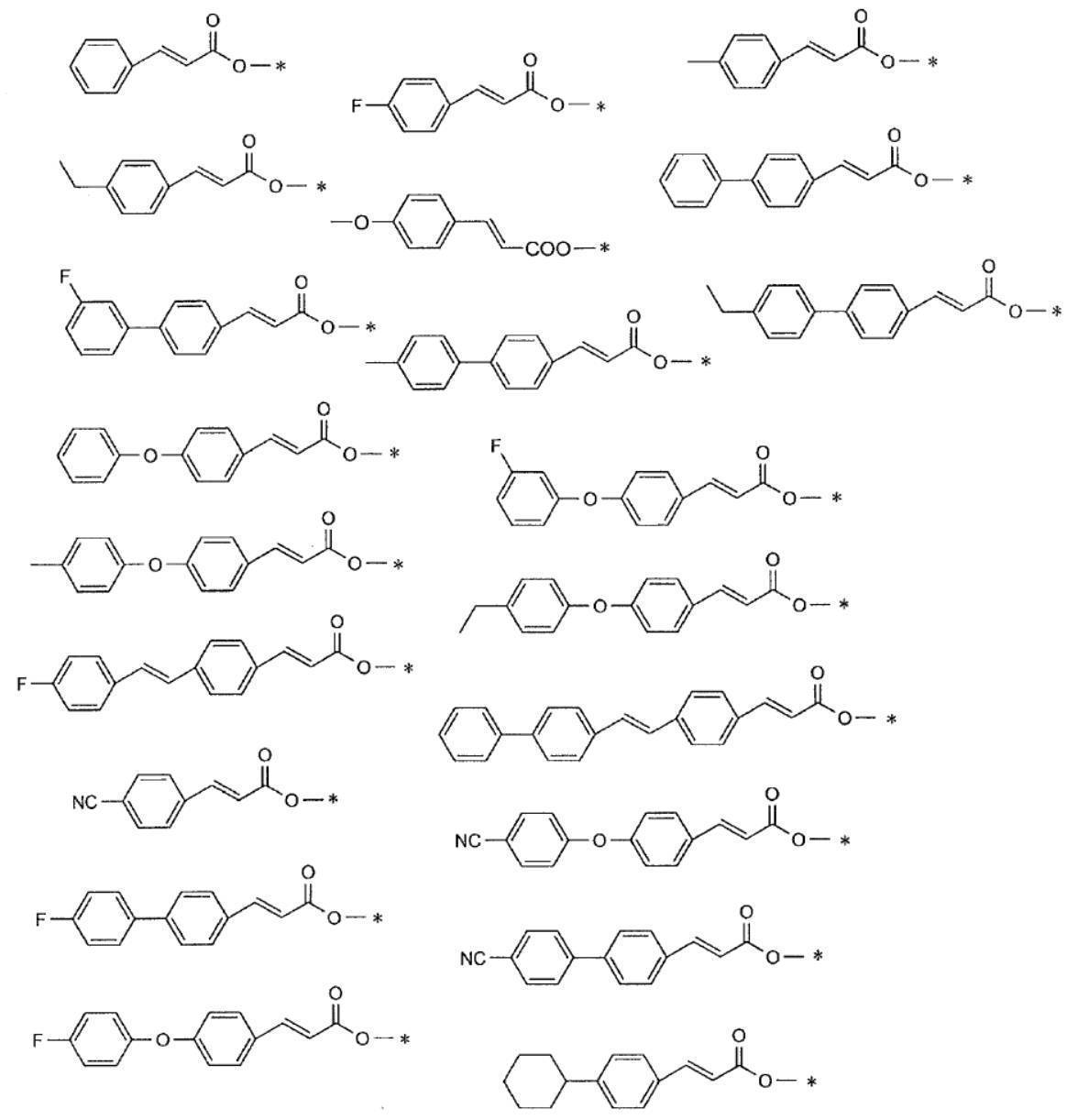

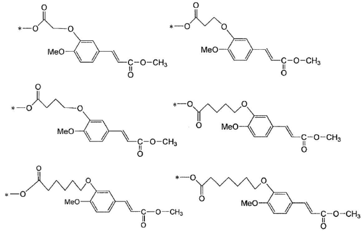
本発明においては、配向性がより向上する理由から、上記重合体Aが、更に、架橋性基を含む構成単位a2を有しているのが好ましい。
上記架橋性基は、熱の作用により硬化反応を起こす熱架橋性基であるのが好ましい。
上記架橋性基を有する構成単位a2としては、例えば、エポキシ基、オキセタニル基、-NH-CH2-O-R(Rは水素原子または炭素数1~20のアルキル基を表す。)で表される基、エチレン性不飽和基、および、ブロックイソシアネート基よりなる群から選ばれた少なくとも1つを含む構成単位が挙げられる。
これらのうち、エポキシ基および/またはオキセタニル基を有する構成単位であることが好ましい。なお、3員環の環状エーテル基はエポキシ基とも呼ばれ、4員環の環状エーテル基はオキセタニル基とも呼ばれる。 <Structural Unit a2 Containing Crosslinkable Group>
In the present invention, it is preferable that the polymer A further has a structural unit a2 containing a crosslinkable group because the orientation is further improved.
The crosslinkable group is preferably a heat crosslinkable group that causes a curing reaction by the action of heat.
The structural unit a2 having a crosslinkable group is represented by, for example, an epoxy group, an oxetanyl group, —NH—CH 2 —O—R (R represents a hydrogen atom or an alkyl group having 1 to 20 carbon atoms). And a structural unit containing at least one selected from the group consisting of an ethylenically unsaturated group and a blocked isocyanate group.
Among these, a structural unit having an epoxy group and / or an oxetanyl group is preferable. A 3-membered cyclic ether group is also called an epoxy group, and a 4-membered cyclic ether group is also called an oxetanyl group.
オキセタニル基を有する構成単位を形成するために用いられるラジカル重合性単量体の具体例としては、例えば、特開2001-330953号公報の段落0011~0016に記載のオキセタニル基を有する(メタ)アクリル酸エステルなどが挙げられ、これらの内容は本願明細書に組み込まれる。
上記エポキシ基および/またはオキセタニル基を有する構成単位a2-1を形成するために用いられるラジカル重合性単量体の具体例としては、メタクリル酸エステル構造を含有するモノマー、アクリル酸エステル構造を含有するモノマーであることが好ましい。 Specific examples of the radical polymerizable monomer used for forming the structural unit having an epoxy group include, for example, glycidyl acrylate, glycidyl methacrylate, glycidyl α-ethyl acrylate, and glycidyl α-n-propyl acrylate. Glycidyl α-n-butyl acrylate, 3,4-epoxybutyl acrylate, 3,4-epoxybutyl methacrylate, 3,4-epoxycyclohexylmethyl acrylate, 3,4-epoxycyclohexyl methacrylate Methyl, α-ethylacrylic acid-3,4-epoxycyclohexylmethyl, o-vinylbenzyl glycidyl ether, m-vinylbenzyl glycidyl ether, p-vinylbenzyl glycidyl ether, described in paragraphs 0031 to 0035 of Japanese Patent No. 4168443 Alicyclic epoch Such compounds may be mentioned containing shea skeleton, the contents of which are incorporated herein.
Specific examples of the radical polymerizable monomer used for forming the structural unit having an oxetanyl group include, for example, a (meth) acryl having an oxetanyl group described in paragraphs 0011 to 0016 of JP-A No. 2001-330953. Acid esters, and the like, the contents of which are incorporated herein.
Specific examples of the radical polymerizable monomer used for forming the structural unit a2-1 having the epoxy group and / or oxetanyl group include a monomer having a methacrylic ester structure and an acrylic ester structure. A monomer is preferred.

エチレン性不飽和基を有する構成単位については、特開2011-215580号公報の段落0072~0090の記載、および、特開2008-256974号公報の段落0013~0031の記載を参酌でき、これらの内容は本願明細書に組み込まれる。 Another example of the structural unit a2 having a crosslinkable group includes a structural unit having an ethylenically unsaturated group. As the structural unit having an ethylenically unsaturated group, a structural unit having an ethylenically unsaturated group in the side chain is preferable, a structure having an ethylenically unsaturated group at the terminal and a side chain having 3 to 16 carbon atoms. Units are more preferred.
Regarding the structural unit having an ethylenically unsaturated group, the description in paragraphs 0072 to 0090 of JP2011-215580A and the description in paragraphs 0013 to 0031 of JP2008-256974A can be referred to, and the contents thereof Is incorporated herein.
本発明においては、上記重合体Aは、上述した構成単位a1および構成単位a2以外の他の構成単位を有していてもよい。共重合体に他の構成単位が含まれることにより、例えば溶媒溶解性、耐熱性、反応性等を高めることができる。
このような他の構成単位を形成するモノマーとしては、例えば、アクリル酸エステル化合物、メタクリル酸エステル化合物、マレイミド化合物、アクリルアミド化合物、アクリロニトリル、マレイン酸無水物、スチレン化合物、ビニル化合物等が挙げられる。 <Other structural units>
In the present invention, the polymer A may have a structural unit other than the structural unit a1 and the structural unit a2 described above. By including other structural units in the copolymer, for example, solvent solubility, heat resistance, reactivity, and the like can be improved.
Examples of such a monomer that forms another structural unit include acrylic ester compounds, methacrylic ester compounds, maleimide compounds, acrylamide compounds, acrylonitrile, maleic anhydride, styrene compounds, and vinyl compounds.
本発明においては、上記重合体Aの含有量は、後述する有機溶媒を含有する場合、溶媒100質量部に対して0.1~50質量部であるのが好ましく、0.5~10質量部であるのがより好ましい。 <Content>
In the present invention, the content of the polymer A is preferably 0.1 to 50 parts by mass, and 0.5 to 10 parts by mass with respect to 100 parts by mass of the solvent when the organic solvent described later is contained. It is more preferable that
本発明の光配向膜用組成物が含有する低分子化合物Bは、シンナメート基を有し、重合体Aよりも分子量が小さい化合物である。
本発明の光配向膜用組成物は、上述した通り、低分子化合物Bを含有することにより、作製される光配向膜の配向性が良好となる。 [Low molecular compound B]
The low molecular compound B contained in the composition for photo-alignment films of the present invention is a compound having a cinnamate group and having a molecular weight smaller than that of the polymer A.
As described above, the composition for a photo-alignment film of the present invention contains the low molecular compound B, so that the alignment property of the produced photo-alignment film becomes good.

また、R1の1価の有機基としては、例えば、炭素数1~20の鎖状または環状のアルキル基、炭素数1~20のアルコキシ基、置換基を有していてもよい炭素数6~20のアリール基等が挙げられ、中でも、炭素数1~20のアルコキシ基が好ましく、炭素数1~6のアルコキシ基がより好ましく、メトキシ基、エトキシ基が更に好ましい。
また、R2の1価の有機基としては、例えば、炭素数1~20の鎖状または環状のアルキル基、置換基を有していてもよい炭素数6~20のアリール基等が挙げられ、中でも、炭素数1~20の鎖状のアルキル基が好ましく、炭素数1~10の分岐鎖状のアルキル基がより好ましい。
また、aは1であるのが好ましく、R1がパラ位に有しているのが好ましい。
また、上述したアリール基が有していてもよい置換基としては、例えば、アルコキシ基、ヒドロキシ基、カルボキシル基、アミノ基等が挙げられる。 In the formula (B1), a represents an integer of 0 to 5, R 1 represents a hydrogen atom or a monovalent organic group, and R 2 represents a monovalent organic group. When a is 2 or more, the plurality of R 1 may be the same or different from each other.
Examples of the monovalent organic group represented by R 1 include, for example, a chain or cyclic alkyl group having 1 to 20 carbon atoms, an alkoxy group having 1 to 20 carbon atoms, and an optionally substituted carbon group having 6 carbon atoms. Among them, an aryl group having 20 to 20 carbon atoms and the like can be mentioned. Among them, an alkoxy group having 1 to 20 carbon atoms is preferable, an alkoxy group having 1 to 6 carbon atoms is more preferable, and a methoxy group and an ethoxy group are further preferable.
Examples of the monovalent organic group represented by R 2 include a linear or cyclic alkyl group having 1 to 20 carbon atoms and an aryl group having 6 to 20 carbon atoms which may have a substituent. Among them, a chain alkyl group having 1 to 20 carbon atoms is preferable, and a branched alkyl group having 1 to 10 carbon atoms is more preferable.
Further, a is preferably 1 , and R 1 is preferably in the para position.
Moreover, as a substituent which the aryl group mentioned above may have, an alkoxy group, a hydroxy group, a carboxyl group, an amino group etc. are mentioned, for example.
本発明においては、作製される光配向膜の配向性がより良好となる理由から、上記低分子化合物Bの含有量は、重合体Aの構成単位a1の質量に対して10~500質量%であるのが好ましく、30~300質量%であるのが好ましい。
また、上記低分子化合物Bの含有量は、後述する有機溶媒を含有する場合、溶媒100質量部に対して0.01~50質量部であるのが好ましく、0.1~10質量部であるのがより好ましい。 <Content>
In the present invention, the content of the low molecular compound B is 10 to 500% by mass with respect to the mass of the structural unit a1 of the polymer A because the orientation of the produced photoalignment film becomes better. It is preferably 30 to 300% by mass.
In addition, when the organic solvent described later is contained, the content of the low molecular compound B is preferably 0.01 to 50 parts by mass, and preferably 0.1 to 10 parts by mass with respect to 100 parts by mass of the solvent. Is more preferable.
本発明の光配向膜用組成物は、配向性がより向上する理由から、架橋性基を含む構成単位a2を有する重合体Aとは別に、架橋性基を有する架橋剤Cを含有していることが好ましい。
上記架橋剤Cの分子量は、1000以下であるのが好ましく、100~500であるのがより好ましい。 [Crosslinking agent C]
The composition for photo-alignment films of the present invention contains a crosslinking agent C having a crosslinkable group separately from the polymer A having the structural unit a2 containing a crosslinkable group, for the reason that the orientation is further improved. It is preferable.
The molecular weight of the crosslinking agent C is preferably 1000 or less, and more preferably 100 to 500.
上記架橋剤Cとしては、例えば、分子内に2個以上のエポキシ基またはオキセタニル基を有する化合物、ブロックイソシアネート化合物(保護されたイソシアナト基を有する化合物)、アルコキシメチル基含有化合物等が挙げられる。
これらのうち、以下に具体例を示す、分子内に2個以上のエポキシ基またはオキセタニル基を有する化合物、ブロックイソシアネート化合物が好ましい。 The crosslinkable group is preferably a heat crosslinkable group that causes a curing reaction by the action of heat.
Examples of the crosslinking agent C include compounds having two or more epoxy groups or oxetanyl groups in the molecule, blocked isocyanate compounds (compounds having a protected isocyanato group), and alkoxymethyl group-containing compounds.
Of these, compounds having two or more epoxy groups or oxetanyl groups in the molecule and block isocyanate compounds, which are shown below as specific examples, are preferred.
分子内に2個以上のエポキシ基を有する化合物の具体例としては、脂肪族エポキシ化合物等を挙げることができる。
これらは市販品として入手できる。例えば、デナコールEX-611、EX-612、EX-614、EX-614B、EX-622、EX-512、EX-521、EX-411、EX-421、EX-313、EX-314、EX-321、EX-211、EX-212、EX-810、EX-811、EX-850、EX-851、EX-821、EX-830、EX-832、EX-841、EX-911、EX-941、EX-920、EX-931、EX-212L、EX-214L、EX-216L、EX-321L、EX-850L、DLC-201、DLC-203、DLC-204、DLC-205、DLC-206、DLC-301、DLC-402(以上ナガセケムテックス(株)製)、セロキサイド2021P、2081、3000、EHPE3150、エポリードGT400、セルビナースB0134、B0177((株)ダイセル製)、などが挙げられる。
これらは1種単独または2種類以上を組み合わせて使用することができる。 <Compound having two or more epoxy groups in the molecule>
Specific examples of the compound having two or more epoxy groups in the molecule include aliphatic epoxy compounds.
These are available as commercial products. For example, Denacol EX-611, EX-612, EX-614, EX-614B, EX-622, EX-512, EX-521, EX-411, EX-421, EX-313, EX-314, EX-321 , EX-211, EX-212, EX-810, EX-811, EX-850, EX-851, EX-821, EX-830, EX-832, EX-841, EX-911, EX-941, EX -920, EX-931, EX-212L, EX-214L, EX-216L, EX-321L, EX-850L, DLC-201, DLC-203, DLC-204, DLC-205, DLC-206, DLC-301 DLC-402 (manufactured by Nagase ChemteX Corporation), Celoxide 2021P, 2081, 3000, EHPE31 0, Epolead GT400, Serubinasu B0134, B0177 ((Ltd.) manufactured by Daicel), and the like.
These can be used alone or in combination of two or more.
分子内に2個以上のオキセタニル基を有する化合物の具体例としては、アロンオキセタンOXT-121、OXT-221、OX-SQ、PNOX(以上、東亜合成(株)製)を用いることができる。 <Compounds having two or more oxetanyl groups in the molecule>
As specific examples of the compound having two or more oxetanyl groups in the molecule, Aron oxetane OXT-121, OXT-221, OX-SQ, and PNOX (above, manufactured by Toagosei Co., Ltd.) can be used.
ブロックイソシアネート化合物は、イソシアネート基が化学的に保護されたブロックイソシアネート基を有する化合物であれば特に制限はないが、硬化性の観点から、1分子中に2以上のブロックイソシアネート基を有する化合物であることが好ましい。
なお、本発明におけるブロックイソシアネート基とは、熱によりイソシアネート基を生成することが可能な基であり、例えば、ブロック剤とイソシアネート基とを反応させイソシアネート基を保護した基が好ましく例示できる。また、上記ブロックイソシアネート基は、90℃~250℃の熱によりイソシアネート基を生成することが可能な基であることが好ましい。
また、ブロックイソシアネート化合物としては、その骨格は特に限定されるものではなく、1分子中にイソシアネート基を2個有するものであればどのようなものでもよく、脂肪族、脂環族または芳香族のポリイソシアネートであってよいが、例えば2,4-トリレンジイソシアネート、2,6-トリレンジイソシアネート、イソホロンジイソシアネート、1,6-ヘキサメチレンジイソシアネート、1,3-トリメチレンジイソシアネート、1,4-テトラメチレンジイソシアネート、2,2,4-トリメチルヘキサメチレンジイソシアネート、2,4,4-トリメチルヘキサメチレンジイソシアネート、1,9-ノナメチレンジイソシアネート、1,10-デカメチレンジイソシアネート、1,4-シクロヘキサンジイソシアネート、2,2’-ジエチルエーテルジイソシアネート、ジフェニルメタン-4,4’-ジイソシアネート、o-キシレンジイソシアネート、m-キシレンジイソシアネート、p-キシレンジイソシアネート、メチレンビス(シクロヘキシルイソシアネート)、シクロヘキサン-1,3-ジメチレンジイソシアネート、シクロヘキサン-1,4-ジメチレンジイソシアネート、1,5-ナフタレンジイソシアネート、p-フェニレンジイソシアネート、3,3’-メチレンジトリレン-4,4’-ジイソシアネート、4,4’-ジフェニルエーテルジイソシアネート、テトラクロロフェニレンジイソシアネート、ノルボルナンジイソシアネート、水素化1,3-キシリレンジイソシアネート、水素化1,4-キシリレンジイソシアネート等のイソシアネート化合物およびこれらの化合物から派生するプレポリマー型の骨格の化合物を好適に用いることができる。これらの中でも、トリレンジイソシアネート(TDI)やジフェニルメタンジイソシアネート(MDI)、ヘキサメチレンジイソシアネート(HDI)、イソホロンジイソシアネート(IPDI)が特に好ましい。 <Block isocyanate compound>
The blocked isocyanate compound is not particularly limited as long as the isocyanate group has a chemically protected blocked isocyanate group, but is a compound having two or more blocked isocyanate groups in one molecule from the viewpoint of curability. It is preferable.
In addition, the blocked isocyanate group in this invention is a group which can produce | generate an isocyanate group with a heat | fever, For example, the group which reacted the blocking agent and the isocyanate group and protected the isocyanate group can illustrate preferably. The blocked isocyanate group is preferably a group capable of generating an isocyanate group by heat at 90 ° C. to 250 ° C.
Further, the skeleton of the blocked isocyanate compound is not particularly limited and may be any as long as it has two isocyanate groups in one molecule, and is aliphatic, alicyclic or aromatic. Polyisocyanates may be used, for example, 2,4-tolylene diisocyanate, 2,6-tolylene diisocyanate, isophorone diisocyanate, 1,6-hexamethylene diisocyanate, 1,3-trimethylene diisocyanate, 1,4-tetramethylene Diisocyanate, 2,2,4-trimethylhexamethylene diisocyanate, 2,4,4-trimethylhexamethylene diisocyanate, 1,9-nonamethylene diisocyanate, 1,10-decamethylene diisocyanate, 1,4-cyclohexane diisocyanate, 2 2'-diethyl ether diisocyanate, diphenylmethane-4,4'-diisocyanate, o-xylene diisocyanate, m-xylene diisocyanate, p-xylene diisocyanate, methylene bis (cyclohexyl isocyanate), cyclohexane-1,3-dimethylene diisocyanate, cyclohexane-1 , 4-Dimethylene diisocyanate, 1,5-naphthalene diisocyanate, p-phenylene diisocyanate, 3,3'-methylene ditolylene-4,4'-diisocyanate, 4,4'-diphenyl ether diisocyanate, tetrachlorophenylene diisocyanate, norbornane diisocyanate ,
上記ブロックイソシアネート化合物のブロック構造を形成するブロック剤としては、オキシム化合物、ラクタム化合物、フェノール化合物、アルコール化合物、アミン化合物、活性メチレン化合物、ピラゾール化合物、メルカプタン化合物、イミダゾール系化合物、イミド系化合物等を挙げることができる。これらの中でも、オキシム化合物、ラクタム化合物、フェノール化合物、アルコール化合物、アミン化合物、活性メチレン化合物、ピラゾール化合物から選ばれるブロック剤が特に好ましい。 Examples of the matrix structure of the blocked isocyanate compound include biuret type, isocyanurate type, adduct type, and bifunctional prepolymer type.
Examples of the blocking agent that forms the block structure of the blocked isocyanate compound include oxime compounds, lactam compounds, phenol compounds, alcohol compounds, amine compounds, active methylene compounds, pyrazole compounds, mercaptan compounds, imidazole compounds, and imide compounds. be able to. Among these, a blocking agent selected from oxime compounds, lactam compounds, phenol compounds, alcohol compounds, amine compounds, active methylene compounds, and pyrazole compounds is particularly preferable.
本発明においては、上記架橋剤Cを含有する場合の含有量は、重合体Aの構成単位a1の100質量部に対して1~1000質量部であるのが好ましく、10~500質量部であるのが好ましい。
また、上記架橋剤Cを含有する場合の含有量は、後述する有機溶媒を含有する場合、溶媒100質量部に対して0.05~50質量部であるのが好ましく、1~10質量部であるのがより好ましい。 <Content>
In the present invention, when the crosslinking agent C is contained, the content is preferably 1 to 1000 parts by mass with respect to 100 parts by mass of the structural unit a1 of the polymer A, and is 10 to 500 parts by mass. Is preferred.
Further, when the crosslinking agent C is contained, the content is preferably 0.05 to 50 parts by mass with respect to 100 parts by mass of the solvent, and preferably 1 to 10 parts by mass when the organic solvent described later is contained. More preferably.
本発明の光配向膜用組成物は、光配向膜を作製する作業性等の観点から、有機溶媒を含有するのが好ましい。
有機溶媒としては、具体的には、例えば、ケトン類(例えば、アセトン、2-ブタノン、メチルイソブチルケトン、シクロヘキサノン、シクロペンタノンなど)、エーテル類(例えば、ジオキサン、テトラヒドロフランなど)、脂肪族炭化水素類(例えば、ヘキサンなど)、脂環式炭化水素類(例えば、シクロヘキサンなど)、芳香族炭化水素類(例えば、トルエン、キシレン、トリメチルベンゼンなど)、ハロゲン化炭素類(例えば、ジクロロメタン、ジクロロエタン、ジクロロベンゼン、クロロトルエンなど)、エステル類(例えば、酢酸メチル、酢酸エチル、酢酸ブチルなど)、水、アルコール類(例えば、エタノール、イソプロパノール、ブタノール、シクロヘキサノールなど)、セロソルブ類(例えば、メチルセロソルブ、エチルセロソルブなど)、セロソルブアセテート類、スルホキシド類(例えば、ジメチルスルホキシドなど)、アミド類(例えば、ジメチルホルムアミド、ジメチルアセトアミドなど)等が挙げられ、これらを1種単独で用いてもよく、2種類以上を併用してもよい。 [Organic solvent]
The composition for photo-alignment film of the present invention preferably contains an organic solvent from the viewpoint of workability for producing the photo-alignment film.
Specific examples of the organic solvent include ketones (eg, acetone, 2-butanone, methyl isobutyl ketone, cyclohexanone, cyclopentanone, etc.), ethers (eg, dioxane, tetrahydrofuran, etc.), aliphatic hydrocarbons, and the like. (E.g., hexane), alicyclic hydrocarbons (e.g., cyclohexane), aromatic hydrocarbons (e.g., toluene, xylene, trimethylbenzene), halogenated carbons (e.g., dichloromethane, dichloroethane, di) Chlorobenzene, chlorotoluene, etc.), esters (eg, methyl acetate, ethyl acetate, butyl acetate, etc.), water, alcohols (eg, ethanol, isopropanol, butanol, cyclohexanol, etc.), cellosolves (eg, methyl cellosolve, ethyl) Rosolve, etc.), cellosolve acetates, sulfoxides (eg, dimethyl sulfoxide, etc.), amides (eg, dimethylformamide, dimethylacetamide, etc.), etc., and these may be used alone or in combination of two or more. You may use together.
本発明の重合性液晶組成物は、上記以外の他の成分を含有してもよく、例えば、架橋触媒、密着改良剤、レベリング剤、界面活性剤、可塑剤などが挙げられる。
なお、本願明細書において、架橋触媒とは架橋性基を有さず、上記架橋剤Cとは異なる化合物を意図する。
架橋触媒としては、例えば、上記架橋剤Cがエポキシ基、オキセタニル基、-NH-CH2-O-R(Rは水素原子または炭素数1~20のアルキル基を表す。)で表される基、および/または、ブロックイソシアネート基を有する場合に、架橋性基間の架橋反応に対する触媒作用を有する成分、および/または、架橋性基間の架橋反応を促進する機能を有する成分として、熱酸発生剤、光酸発生剤、金属キレート化合物、および、硬化促進剤等が挙げられる。
上記熱酸発生剤としては、熱により酸を放出する化合物であれば特に限定されず、例えば、有機ハロゲン化化合物、ジスルホン酸化合物、オキシムエステル化合物、スルホン酸エステル化合物、リン酸エステル化合物、ホスホン酸エステル化合物、スルホニウム、ヨードニウム、ジアゾニウム、ピリジニウム、ホスホニウム、および、アンモニウム等のオニウム塩化合物等の公知の熱酸発生剤が挙げられる。
上記光酸発生剤としては、波長300nm以上、好ましくは波長300~450nmの活性光線に感応し、酸を発生する化合物が好ましいが、その化学構造に限定されるものではない。また、波長300nm以上の活性光線に直接感応しない光酸発生剤のうち、増感剤と併用することによって波長300nm以上の活性光線に感応し、酸を発生する化合物を用いることもできる。上記光酸発生剤の例として、トリクロロメチル-s-トリアジン類、スルホニウム塩およびヨードニウム塩(オニウム塩)、第四級アンモニウム塩類、ジアゾメタン化合物、イミドスルホネート化合物、及び、オキシムスルホネート化合物などを挙げることができる。これらのなかでも、絶縁性、および、感度の観点から、オキシムスルホネート化合物を用いることが好ましい。これら光酸発生剤は、1種単独又は2種類以上を組み合わせて使用することができる。トリクロロメチル-s-トリアジン類、ジアリールヨードニウム塩類、トリアリールスルホニウム塩類、第四級アンモニウム塩類、及び、ジアゾメタン誘導体の具体例としては、特開2011-221494号公報の段落[0083]~[0088]に記載の化合物が例示できる。
上記金属キレート化合物としては、アルミニウム、チタニウム及びジルコニウムからなる群から選択される少なくとも1種の金属のアセチルアセトン錯体又はアセト酢酸錯体が好ましい。具体的には、アルミニウムのキレート化合物として、例えばジイソプロポキシエチルアセトアセテートアルミニウム、ジイソプロポキシアセチルアセトネートアルミニウム、イソプロポキシビス(エチルアセトアセテート)アルミニウム、イソプロポキシビス(アセチルアセトネート)アルミニウム、トリス(エチルアセトアセテート)アルミニウム、トリス(アセチルアセトネート)アルミニウム、および、モノアセチルアセトネートビス(エチルアセトアセテート)アルミニウムなど;チタニウムのキレート化合物として、例えばジイソプロポキシビス(エチルアセトアセテート)チタニウム、および、ジイソプロポキシビス(アセチルアセトネート)チタニウムなど;ジルコニウムのキレート化合物として、例えばトリ-n-ブトキシエチルアセトアセテートジルコニウム、ジ-n-ブトキシビス(エチルアセトアセテート)ジルコニウム、n-ブトキシトリス(エチルアセトアセテート)ジルコニウム、テトラキス(n-プロピルアセトアセテート)ジルコニウム、テトラキス(アセチルアセトネート)ジルコニウム、および、テトラキス(エチルアセトアセテート)ジルコニウムなどを、それぞれ挙げることができる。金属キレート化合物としては、これらのうちから選択される1種を単独で又は2種以上を組み合わせて使用することができる。
上記架橋触媒としては、フェノール基、シラノール基、チオール基、リン酸基、スルホン酸基、カルボキシル基、および、カルボン酸無水物基などを有する化合物を使用することができる。これらのうち、フェノール基、シラノール基またはカルボキシル基を有する化合物が好ましく、フェノール基又はシラノール基を有する化合物がより好ましい。
フェノール基またはシラノール基を有する化合物の具体例としては、フェノール基を有する架橋触媒として、例えばシアノフェノール、ニトロフェノール、メトキシフェノキシフェノール、チオフェノキシフェノール、ビス(4-ヒドロキシフェニル)スルホン、ビス(ヒドロキシナフチル)スルホン、(3-ヒドロキシフェニル)(4-ヒドロキシフェニル)スルホン、フェニル(4-ヒドロキシフェニル)スルホン、(メトキシフェニル)(4-ヒドロキシフェニル)スルホン、4-ベンジルフェノール、および、2,2-ビス(4-ヒドロキシフェニル)プロパンなどを;シラノール基を有する硬化促進剤として、例えばトリメチルシラノール、トリエチルシラノール、1,1,3,3-テトラフェニル-1,3-ジシロキサンジオール、1,4-ビス(ヒドロキシジメチルシリル)ベンゼン、トリフェニルシラノール、トリ(p-トリル)シラノール、トリ(m-トリフルオロメチルフェニル)シラノール、トリ(o-トリフルオロメチルフェニル)シラノール、トリ(m-フルオロフェニル)シラノール、トリ(o-フルオロフェニル)シラノール、ジフェニルシランジオール、ジ(o-トリル)シランジオールなどを、それぞれ挙げることができる。なお、硬化促進剤としては、これらのうちから選択される1種を単独で又は2種以上を組み合わせて使用することができる。 [Other ingredients]
The polymerizable liquid crystal composition of the present invention may contain components other than those described above, and examples thereof include a crosslinking catalyst, an adhesion improving agent, a leveling agent, a surfactant, and a plasticizer.
In the present specification, the crosslinking catalyst means a compound that does not have a crosslinkable group and is different from the crosslinking agent C.
Examples of the crosslinking catalyst include a group in which the crosslinking agent C is represented by an epoxy group, an oxetanyl group, —NH—CH 2 —O—R (R represents a hydrogen atom or an alkyl group having 1 to 20 carbon atoms). And / or a component having a catalytic action for a cross-linking reaction between crosslinkable groups and / or a component having a function of promoting a cross-linking reaction between crosslinkable groups when having a blocked isocyanate group Agents, photoacid generators, metal chelate compounds, and curing accelerators.
The thermal acid generator is not particularly limited as long as it is a compound that releases an acid by heat. For example, an organic halogenated compound, a disulfonic acid compound, an oxime ester compound, a sulfonic acid ester compound, a phosphoric acid ester compound, a phosphonic acid Known thermal acid generators such as ester compounds, sulfonium, iodonium, diazonium, pyridinium, phosphonium, and onium salt compounds such as ammonium can be used.
The photoacid generator is preferably a compound that reacts with actinic rays having a wavelength of 300 nm or more, preferably 300 to 450 nm, and generates an acid, but is not limited to its chemical structure. In addition, among photoacid generators that are not directly sensitive to actinic rays having a wavelength of 300 nm or longer, a compound that reacts with actinic rays having a wavelength of 300 nm or longer to generate an acid when used in combination with a sensitizer can be used. Examples of the photoacid generator include trichloromethyl-s-triazines, sulfonium salts and iodonium salts (onium salts), quaternary ammonium salts, diazomethane compounds, imide sulfonate compounds, and oxime sulfonate compounds. it can. Among these, it is preferable to use an oxime sulfonate compound from the viewpoint of insulation and sensitivity. These photoacid generators can be used singly or in combination of two or more. Specific examples of trichloromethyl-s-triazines, diaryliodonium salts, triarylsulfonium salts, quaternary ammonium salts, and diazomethane derivatives are described in paragraphs [0083] to [0088] of JP2011-212494A. The compounds described can be exemplified.
The metal chelate compound is preferably an acetylacetone complex or acetoacetic acid complex of at least one metal selected from the group consisting of aluminum, titanium and zirconium. Specifically, as an aluminum chelate compound, for example, diisopropoxyethyl acetoacetate aluminum, diisopropoxyacetylacetonate aluminum, isopropoxybis (ethylacetoacetate) aluminum, isopropoxybis (acetylacetonate) aluminum, tris ( Ethyl acetoacetate) aluminum, tris (acetylacetonate) aluminum, and monoacetylacetonate bis (ethylacetoacetate) aluminum; titanium chelate compounds such as diisopropoxybis (ethylacetoacetate) titanium and di Isopropoxybis (acetylacetonate) titanium, etc .; as a chelate compound of zirconium, for example, tri-n-butoxy Tylacetoacetate zirconium, di-n-butoxybis (ethylacetoacetate) zirconium, n-butoxytris (ethylacetoacetate) zirconium, tetrakis (n-propylacetoacetate) zirconium, tetrakis (acetylacetonate) zirconium, and tetrakis ( And ethyl acetoacetate) zirconium. As a metal chelate compound, 1 type selected from these can be used individually or in combination of 2 or more types.
As said crosslinking catalyst, the compound which has a phenol group, a silanol group, a thiol group, a phosphoric acid group, a sulfonic acid group, a carboxyl group, a carboxylic anhydride group, etc. can be used. Of these, compounds having a phenol group, silanol group or carboxyl group are preferred, and compounds having a phenol group or silanol group are more preferred.
Specific examples of the compound having a phenol group or silanol group include a crosslinking catalyst having a phenol group such as cyanophenol, nitrophenol, methoxyphenoxyphenol, thiophenoxyphenol, bis (4-hydroxyphenyl) sulfone, bis (hydroxynaphthyl). ) Sulfone, (3-hydroxyphenyl) (4-hydroxyphenyl) sulfone, phenyl (4-hydroxyphenyl) sulfone, (methoxyphenyl) (4-hydroxyphenyl) sulfone, 4-benzylphenol, and 2,2-bis (4-hydroxyphenyl) propane and the like; as a curing accelerator having a silanol group, for example, trimethylsilanol, triethylsilanol, 1,1,3,3-tetraphenyl-1,3-
本発明の光配向膜は、上述した本発明の光配向膜用組成物を用いて作製され、光配向膜用組成物に含まれる重合体Aおよび低分子化合物Bのシンナメート基が二量化したシクロブタン環、および/または、上記シンナメート基が異性化した構造を有する光配向膜である。 [Photo-alignment film]
The photo-alignment film of the present invention is produced using the above-described composition for photo-alignment film of the present invention, and cyclobutane in which the cinnamate groups of the polymer A and the low-molecular compound B contained in the composition for photo-alignment film are dimerized. A photo-alignment film having a structure in which a ring and / or the cinnamate group is isomerized.
本発明の光配向膜は、上述した本発明の光配向膜用組成物を用いる以外は従来公知の製造方法により製造することができ、例えば、上述した本発明の光配向膜用組成物を支持体表面に塗布する塗布工程と、光配向膜用組成物の塗膜に対し、偏光または塗膜表面に対して斜め方向から非偏光を照射する光照射工程とを有する製造方法により作製することができる。
なお、支持体については、後述する本発明の光学積層体において説明する。 〔Production method〕
The photo-alignment film of the present invention can be produced by a conventionally known production method except that the above-described composition for a photo-alignment film of the present invention is used. For example, the photo-alignment film of the present invention described above is supported. It can be produced by a production method having a coating step of applying to the body surface and a light irradiation step of irradiating the coating film of the composition for photo-alignment film with polarized light or non-polarized light from an oblique direction with respect to the coating film surface. it can.
In addition, about a support body, it demonstrates in the optical laminated body of this invention mentioned later.
塗布工程における塗布方法は特に限定されず、目的に応じて適宜選択することができ、例えば、スピンコーティング、ダイコーティング、グラビアコーティング、フレキソ印刷、インクジェット印刷などが挙げられる。 <Application process>
The application method in the application step is not particularly limited and can be appropriately selected depending on the purpose. Examples thereof include spin coating, die coating, gravure coating, flexographic printing, and inkjet printing.
光照射工程において、光配向膜用組成物の塗膜に対して照射する偏光は特に制限はなく、例えば、直線偏光、円偏光、楕円偏光などが挙げられ、中でも、直線偏光が好ましい。
また、非偏光を照射する「斜め方向」とは、塗膜表面の法線方向に対して極角θ(0<θ<90°)傾けた方向である限り、特に制限はなく、目的に応じて適宜選択することができるが、θが20~80°であることが好ましい。 <Light irradiation process>
In the light irradiation step, the polarized light applied to the coating film of the composition for photo-alignment film is not particularly limited, and examples thereof include linearly polarized light, circularly polarized light, and elliptically polarized light. Among these, linearly polarized light is preferable.
Further, the “oblique direction” for irradiating non-polarized light is not particularly limited as long as it is a direction inclined by a polar angle θ (0 <θ <90 °) with respect to the normal direction of the coating film surface, and depending on the purpose. The angle θ is preferably 20 to 80 °.
また、偏光または非偏光を照射するための光源としては、例えば、キセノンランプ、高圧水銀ランプ、超高圧水銀ランプ、メタルハライドランプなどが挙げられる。このような光源から得た紫外線や可視光線に対して、干渉フィルタや色フィルタなどを用いることで、照射する波長範囲を制限することができる。また、これらの光源からの光に対して、偏光フィルタや偏光プリズムを用いることで、直線偏光を得ることができる。 The wavelength in polarized light or non-polarized light is not particularly limited as long as the coating film of the composition for photo-alignment film can impart alignment controllability to liquid crystalline molecules. Etc. Of these, near-ultraviolet rays of 250 nm to 450 nm are particularly preferable.
Examples of the light source for irradiating polarized light or non-polarized light include a xenon lamp, a high-pressure mercury lamp, an ultrahigh-pressure mercury lamp, and a metal halide lamp. By using an interference filter, a color filter, or the like for ultraviolet rays or visible light obtained from such a light source, the wavelength range to be irradiated can be limited. Moreover, linearly polarized light can be obtained by using a polarizing filter or a polarizing prism for the light from these light sources.
偏光または非偏光の照度としては、光配向膜用組成物の塗膜に、液晶性分子に対する配向制御能を付与することができる限り、特に制限はないが、0.1~300mW/cm2が好ましく、1~100mW/cm2がより好ましい。 The integrated light quantity of polarized light or non-polarized light is not particularly limited as long as it can provide alignment controllability for liquid crystalline molecules to the coating film of the composition for photo-alignment film, but is not particularly limited, but is 1 to 300 mJ. / Cm 2 is preferable, and 5 to 100 mJ / cm 2 is more preferable.
The illuminance of polarized light or non-polarized light is not particularly limited as long as it can provide the alignment controllability for liquid crystalline molecules to the coating film of the composition for photo-alignment film, but is 0.1 to 300 mW /
本発明の光学積層体は、上述した本発明の光配向膜と、光配向膜上に設けられ、液晶性化合物を含有する光学異方性層とを有する、光学積層体である。
また、本発明の光学積層体は、更に支持体を有しているのが好ましく、具体的には、支持体と光配向膜と光学異方性層とをこの順に有しているのが好ましい。
また、本発明の光学積層体は、上述した順で支持体を有している場合、支持体と光配向膜との間に、樹脂層を有していることが好ましく、更に、樹脂層と光配向膜との間に、他の光学異方性層を有していることが好ましい。 [Optical laminate]
The optical laminate of the present invention is an optical laminate having the above-described photo-alignment film of the present invention and an optically anisotropic layer provided on the photo-alignment film and containing a liquid crystalline compound.
Further, the optical layered body of the present invention preferably further has a support, and specifically, preferably has a support, a photo-alignment film, and an optically anisotropic layer in this order. .
Moreover, when the optical laminated body of this invention has a support body in the order mentioned above, it is preferable to have a resin layer between a support body and a photo-alignment film, It is preferable to have another optically anisotropic layer between the photo-alignment film.
図1Aに示す光学積層体10は、光配向膜1と、光学異方性層2とをこの順で有する。
図1Bに示す光学積層体20は、支持体3と、光配向膜1と、光学異方性層2とをこの順で有する。
図1Cに示す光学積層体30は、ポリマーフィルム3bおよび偏光子3aと、光配向膜1と、光学異方性層2とをこの順で有する。
図1Dに示す光学積層体40は、支持体3と、光配向膜1と、第1光学異方性層2aおよび他の第2光学異方性層2bとをこの順で有する。
図1Eに示す光学積層体50は、仮支持体3cと、樹脂層4と、光配向膜1と、光学異方性層2とをこの順で有する。
図1Fに示す光学積層体60は、仮支持体3cと、樹脂層4と、他の光学異方性層6と、光配向膜1と、光学異方性層2とをこの順で有する。
図1Gに示す光学積層体70は、樹脂層4と、他の光学異方性層6と、光配向膜1と、光学異方性層2と、接着剤層または粘着剤層5と、偏光子3aおよびポリマーフィルム3bとをこの順で有する。 1A to 1G are schematic cross-sectional views each showing an example of the optical layered body of the present invention. 1A to 1G are schematic diagrams, and the relationship between the thicknesses of the layers does not necessarily match the actual one.
The optical
The optical
The optical
The optical
The optical
The optical
1G includes an optical
本発明の光学積層体が有する光学異方性層は、液晶性化合物を含有する光学異方性層であれば特に限定されず、従来公知の光学異方性層を適宜採用して用いることができる。
このような光学異方性層は、重合性基を有する液晶性化合物を含有する組成物(以下、「光学異方性層形成用組成物」ともいう。)を硬化させて得られる層であるのが好ましく、単層構造であってもよく、例えば、図1Dに示すような複数層を積層した構造(積層体)であってもよい。
以下に、光学異方性層形成用組成物が含有している液晶性化合物および任意の添加剤について説明する。 (Optically anisotropic layer)
The optically anisotropic layer of the optical layered body of the present invention is not particularly limited as long as it is an optically anisotropic layer containing a liquid crystalline compound, and a conventionally known optically anisotropic layer may be appropriately employed and used. it can.
Such an optically anisotropic layer is a layer obtained by curing a composition containing a liquid crystal compound having a polymerizable group (hereinafter also referred to as “optically anisotropic layer forming composition”). Preferably, it may have a single layer structure, for example, a structure (stacked body) in which a plurality of layers as shown in FIG. 1D are stacked.
Below, the liquid crystalline compound and optional additives contained in the composition for forming an optically anisotropic layer will be described.
光学異方性層形成用組成物が含有する液晶性化合物は、重合性基を有する液晶性化合物である。
一般的に、液晶性化合物はその形状から、棒状タイプと円盤状タイプに分類できる。更にそれぞれ低分子と高分子タイプがある。高分子とは一般に重合度が100以上のものを指す(高分子物理・相転移ダイナミクス,土井 正男 著,2頁,岩波書店,1992)。
本発明においては、いずれの液晶性化合物を用いることもできるが、棒状液晶性化合物またはディスコティック液晶性化合物を用いるのが好ましく、棒状液晶性化合物を用いるのがより好ましい。 <Liquid crystal compound>
The liquid crystalline compound contained in the composition for forming an optically anisotropic layer is a liquid crystalline compound having a polymerizable group.
In general, liquid crystal compounds can be classified into a rod-shaped type and a disk-shaped type based on their shapes. In addition, there are low and high molecular types, respectively. Polymer generally refers to a polymer having a degree of polymerization of 100 or more (Polymer Physics / Phase Transition Dynamics, Masao Doi, 2 pages, Iwanami Shoten, 1992).
In the present invention, any liquid crystal compound can be used, but a rod-like liquid crystal compound or a discotic liquid crystal compound is preferably used, and a rod-like liquid crystal compound is more preferably used.
光学異方性層形成用組成物には、上述した液晶性化合物以外の成分が含まれていてもよい。
例えば、光学異方性層形成用組成物には、重合開始剤が含まれていてもよい。使用される重合開始剤は、重合反応の形式に応じて選択され、例えば、熱重合開始剤、光重合開始剤が挙げられる。例えば、光重合開始剤の例には、α-カルボニル化合物、アシロインエーテル、α-炭化水素置換芳香族アシロイン化合物、多核キノン化合物、トリアリールイミダゾールダイマーとp-アミノフェニルケトンとの組み合わせなどが挙げられる。
重合開始剤の使用量は、組成物の全固形分に対して、0.01~20質量%であることが好ましく、0.5~5質量%であることがより好ましい。 <Additives>
The composition for forming an optically anisotropic layer may contain components other than the liquid crystalline compounds described above.
For example, the composition for forming an optically anisotropic layer may contain a polymerization initiator. The polymerization initiator used is selected according to the type of the polymerization reaction, and examples thereof include a thermal polymerization initiator and a photopolymerization initiator. Examples of photopolymerization initiators include α-carbonyl compounds, acyloin ethers, α-hydrocarbon substituted aromatic acyloin compounds, polynuclear quinone compounds, combinations of triarylimidazole dimers and p-aminophenyl ketones. It is done.
The amount of the polymerization initiator used is preferably 0.01 to 20% by mass, more preferably 0.5 to 5% by mass, based on the total solid content of the composition.
重合性モノマーとしては、ラジカル重合性またはカチオン重合性の化合物が挙げられる。好ましくは、多官能性ラジカル重合性モノマーであり、上記の重合性基含有の液晶性化合物と共重合性のものが好ましい。例えば、特開2002-296423号公報中の段落[0018]~[0020]に記載のものが挙げられる。
重合性モノマーの含有量は、液晶性化合物の全質量に対して、1~50質量%であることが好ましく、2~30質量%であることがより好ましい。 Moreover, the polymerizable monomer may be contained in the composition for optically anisotropic layer formation from the point of the uniformity of a coating film and the intensity | strength of a film | membrane.
Examples of the polymerizable monomer include radically polymerizable or cationically polymerizable compounds. Preferably, it is a polyfunctional radically polymerizable monomer and is preferably copolymerizable with the polymerizable group-containing liquid crystalline compound. Examples thereof include those described in paragraphs [0018] to [0020] in JP-A No. 2002-296423.
The content of the polymerizable monomer is preferably 1 to 50% by mass and more preferably 2 to 30% by mass with respect to the total mass of the liquid crystal compound.
界面活性剤としては、従来公知の化合物が挙げられるが、特にフッ素系化合物が好ましい。具体的には、例えば特開2001-330725号公報中の段落[0028]~[0056]に記載の化合物、特願2003-295212号明細書中の段落[0069]~[0126]に記載の化合物が挙げられる。 Further, the composition for forming an optically anisotropic layer may contain a surfactant from the viewpoint of the uniformity of the coating film and the strength of the film.
Examples of the surfactant include conventionally known compounds, and fluorine compounds are particularly preferable. Specifically, for example, compounds described in paragraphs [0028] to [0056] in JP-A No. 2001-330725, compounds described in paragraphs [0069] to [0126] in Japanese Patent Application No. 2003-295212, and the like. Is mentioned.
更に、光学異方性層形成用組成物には、上記成分以外に、密着改良剤、可塑剤、ポリマーなどが含まれていてもよい。 Further, the composition for forming an optically anisotropic layer includes a vertical alignment accelerator such as a polarizer interface side vertical alignment agent and an air interface side vertical alignment agent, a polarizer interface side horizontal alignment agent, and air. Various alignment agents such as a horizontal alignment accelerator such as an interface side horizontal alignment agent may be contained.
Furthermore, in addition to the above components, the composition for forming an optically anisotropic layer may contain an adhesion improving agent, a plasticizer, a polymer, and the like.
光学異方性層形成用組成物の塗布は、公知の方法(例えば、ワイヤーバーコーティング法、押し出しコーティング法、ダイレクトグラビアコーティング法、リバースグラビアコーティング法、ダイコーティング法)により実施できる。 The method for forming an optically anisotropic layer using the composition for forming an optically anisotropic layer having such a component is not particularly limited. For example, the optically anisotropic layer is formed on the above-described photo-alignment film of the present invention. It can form by apply | coating the composition for formation, forming a coating film, and performing a hardening process (ultraviolet irradiation (light irradiation process) or heat processing) with respect to the obtained coating film.
The composition for forming an optically anisotropic layer can be applied by a known method (for example, a wire bar coating method, an extrusion coating method, a direct gravure coating method, a reverse gravure coating method, or a die coating method).
また、IPSモード液晶表示装置における光学補償がより向上する理由から、上記光学異方性層は、例えば、図1Dに示すような複数層を積層した構造のうち、棒状液晶性化合物をホモジニアス(水平)配向させた第1光学異方性層と、棒状液晶性化合物をホメオトロピック(垂直)配向させた第2光学異方性層とを有しているのが好ましい。 In the present invention, when the optically anisotropic layer functions as a positive A plate, a liquid crystal display that does not require a pre-tilt angle of the driving liquid crystal, particularly an IPS (In-Plane-Switching) mode liquid crystal display device. An optically anisotropic layer in which a rod-like liquid crystalline compound is homogeneously (horizontal) oriented is preferable because it is useful for optical compensation in the apparatus.
Further, for the reason that the optical compensation in the IPS mode liquid crystal display device is further improved, the optically anisotropic layer is made of, for example, a rod-like liquid crystalline compound homogeneous (horizontal) in a structure in which a plurality of layers as shown in FIG. 1D are laminated. It is preferable to have an oriented first optically anisotropic layer and a second optically anisotropic layer in which a rod-like liquid crystal compound is homeotropically (vertically) oriented.
0.75<Re(450)/Re(550)<1.00 ・・・(II)
0.75<Rth(450)/Rth(550)≦1.02 ・・・(III)
ここで、式(II)中、Re(450)は、光学異方性層の波長450nmにおける面内レターデーションを表し、Re(550)は、光学異方性層の波長550nmにおける面内レターデーションを表す。式(III)中、Rth(450)は、光学異方性層の波長450nmにおける厚み方向のレターデーションを表し、Rth(550)は、光学異方性層の波長550nmにおける厚みレターデーションを表す。
また、面内レターデーションおよび厚み方向のレターデーションの値は、AxoScan OPMF-1(オプトサイエンス社製)を用い、測定波長の光を用いて測定した値をいう。 The optically anisotropic layer of the optical laminate of the present invention preferably satisfies the following formula (II) or (III) from the viewpoint of imparting excellent viewing angle characteristics.
0.75 <Re (450) / Re (550) <1.00 (II)
0.75 <Rth (450) / Rth (550) ≦ 1.02 (III)
Here, in formula (II), Re (450) represents the in-plane retardation of the optically anisotropic layer at a wavelength of 450 nm, and Re (550) represents the in-plane retardation of the optically anisotropic layer at a wavelength of 550 nm. Represents. In formula (III), Rth (450) represents the retardation in the thickness direction of the optically anisotropic layer at a wavelength of 450 nm, and Rth (550) represents the thickness retardation of the optically anisotropic layer at a wavelength of 550 nm.
Further, the values of in-plane retardation and retardation in the thickness direction are values measured using AxoScan OPMF-1 (manufactured by Optoscience) and using light having a measurement wavelength.
本発明の光学積層体は、後述する樹脂層と、上述した光配向膜の間に、上述した光学異方性層とは異なる、他の光学異方性層を有することが好ましい。
他の光学異方性層としては特に制限されず、公知の光学異方性層を用いることができる。他の光学異方性層は、液晶性化合物を含有することが好ましく、光学異方性層形成用組成物を硬化させて得られる層であるのがより好ましい。
なお、上記液晶性化合物、及び、光学異方性層用組成物としては特に制限されないが、例えば、光学異方性層が含有する液晶性化合物、及び、光学異方性層形成用組成物として既に説明した態様が挙げられる。他の光学異方性層についても、優れた視野角特性を付与する観点から、上記式(II)または(III)を満たすのが好ましい。
また、IPS(In-Plane-Switching)モード液晶表示装置における光学補償がより向上する理由から、例えば、図1Fに示すような複数層を積層した構造のうち、棒状液晶性化合物をホモジニアス(水平)配向させた上記光学異方性層と、棒状液晶性化合物をホメオトロピック(垂直)配向させた上記他の光学異方性層とを有しているのが好ましい。 [Other optically anisotropic layers]
The optical layered body of the present invention preferably has another optically anisotropic layer different from the optically anisotropic layer described above between the resin layer described later and the above-described photoalignment film.
Other optically anisotropic layers are not particularly limited, and known optically anisotropic layers can be used. The other optically anisotropic layer preferably contains a liquid crystal compound, and more preferably a layer obtained by curing the composition for forming an optically anisotropic layer.
In addition, although it does not restrict | limit especially as said liquid crystalline compound and a composition for optical anisotropic layers, For example, as a liquid crystalline compound which an optical anisotropic layer contains, and a composition for optical anisotropic layer formation The aspect already demonstrated is mentioned. The other optically anisotropic layers also preferably satisfy the above formula (II) or (III) from the viewpoint of imparting excellent viewing angle characteristics.
Also, for the reason that optical compensation in an IPS (In-Plane-Switching) mode liquid crystal display device is further improved, for example, in a structure in which a plurality of layers are laminated as shown in FIG. It is preferable to have the aligned optically anisotropic layer and the other optically anisotropic layer in which a rod-like liquid crystalline compound is homeotropically (vertically) aligned.
本発明の光学積層体に用いられる任意の樹脂層は、2種類以上の多官能モノマーを重合硬化させて得られる層であることが好ましい。
多官能モノマーに含まれる重合性基が(メタ)アクリロイル基であることがより好ましく、2種類以上の多官能モノマーのうち、少なくとも1種類は、下記式(X)で表される部分構造(以下、「トリシクロデカン骨格」ともいう。)を有するモノマーであることが好ましい。下記式(X)で表されるトリシクロデカン骨格を有するモノマーと多官能モノマーとを重合硬化させて得られる樹脂層を用いることで、樹脂層の膜強度を保持しつつ、後述する仮支持体との接着力を低減することができ、偏光子に光学異方性層を容易に転写させることができる。
以下、樹脂層の原料について詳述した後に樹脂層の製造手順などについて詳述する。

The arbitrary resin layer used in the optical laminate of the present invention is preferably a layer obtained by polymerizing and curing two or more types of polyfunctional monomers.
The polymerizable group contained in the polyfunctional monomer is more preferably a (meth) acryloyl group, and at least one of the two or more polyfunctional monomers is a partial structure represented by the following formula (X) (hereinafter referred to as the following structure). And a monomer having a "tricyclodecane skeleton"). By using a resin layer obtained by polymerizing and curing a monomer having a tricyclodecane skeleton represented by the following formula (X) and a polyfunctional monomer, the temporary support described later is maintained while maintaining the film strength of the resin layer. The optically anisotropic layer can be easily transferred to the polarizer.
Hereinafter, after detailed description of the raw material of the resin layer, the manufacturing procedure of the resin layer and the like will be described in detail.
多官能モノマーは、光や熱を用いて重合可能な化合物であり、重合硬化して樹脂層を構成する成分となる。
多官能モノマーには、複数の重合性基が含まれる。重合性基の定義は、上述の通りであり、(メタ)アクリロイル基が好ましい。
多官能モノマー中に含まれる重合性基の数は特に制限されず、複数(2以上)であればよく、樹脂層の膜強度がより優れる点で3~32が好ましく、3~20がより好ましい。 <Multifunctional monomer>
The polyfunctional monomer is a compound that can be polymerized using light or heat, and becomes a component that forms a resin layer by polymerization and curing.
The polyfunctional monomer includes a plurality of polymerizable groups. The definition of a polymeric group is as above-mentioned, and a (meth) acryloyl group is preferable.
The number of polymerizable groups contained in the polyfunctional monomer is not particularly limited, and may be a plurality (2 or more), preferably 3 to 32, more preferably 3 to 20 in terms of more excellent film strength of the resin layer. .
これらの多官能モノマーは、1種のみを用いてもよいし、2種類以上を合わせて使用してもよい。
なお、(メタ)アクリレートとは、アクリレートまたはメタアクリレートを意味する表記である。 Specific examples of the polyfunctional monomer include, for example, ethylene glycol di (meth) acrylate, triethylene glycol di (meth) acrylate, tetramethylene glycol di (meth) acrylate, propylene glycol di (meth) acrylate, and polyethylene glycol di (meth). ) Acrylate, polypropylene glycol di (meth) acrylate, 1,3-butanediol di (meth) acrylate, trimethylolethane triacrylate, trimethylolpropane tri (meth) acrylate, trimethylolpropane di (meth) acrylate, neopentyl glycol Di (meth) acrylate, pentaerythritol tetra (meth) acrylate, pentaerythritol tri (meth) acrylate, pentaerythritol hexa (meth) Acrylate, dipentaerythritol hexa (meth) acrylate, dipentaerythritol penta (meth) acrylate, 1,4-hexanediol (meth) acrylate, hexanediol di (meth) acrylate, trimethylolpropane tri (acryloyloxypropyl) ether, Tri (acryloyloxyethyl) isocyanurate, tri (acryloyloxyethyl) cyanurate, glycerin tri (meth) acrylate, trimethylolpropane or glycerin and other polyfunctional alcohols after addition reaction with ethylene oxide or propylene oxide (meth) acrylate And polyfunctional (meth) acrylates such as those obtained.
These polyfunctional monomers may be used alone or in combination of two or more.
In addition, (meth) acrylate is a description meaning acrylate or methacrylate.
更に、樹脂層形成用組成物には、上記成分以外に、密着改良剤、可塑剤、ポリマーなどが含まれていてもよい。 Moreover, the organic solvent may be contained in the composition for resin layer formation. As an organic solvent, the thing similar to what was demonstrated in the composition for photo-alignment films | membranes of this invention mentioned above can be mentioned.
Further, the resin layer forming composition may contain an adhesion improving agent, a plasticizer, a polymer and the like in addition to the above components.
本発明の光学積層体は、上述したように、光学異方性層を形成するための基材として支持体を有していてもよい。
このような支持体としては、例えば、偏光子、ポリマーフィルム等が挙げられ、これらが組み合わされたもの、例えば、偏光子とポリマーフィルムとの積層体、ポリマーフィルムと偏光子とポリマーフィルムとの積層体などであってもよい。
また、支持体は、光学異方性層を形成した後に、剥離可能な仮支持体(以下、単に「仮支持体」とのみ表記する場合もある。)であってもよい。具体的には、仮支持体として機能するポリマーフィルムを光学積層体から剥離して、光学異方性層を提供できるものであってもよい。例えば、光学異方性層と仮支持体を含む光学積層体を用意し、光学積層体の光学異方性層側を、偏光子を含む支持体に粘着剤または接着剤で貼り合わせた後、前記光学異方性層に含まれる仮支持体を剥離することで、偏光子を含む支持体と光学異方性層との積層体を提供できるものであってもよい。 [Support]
As described above, the optical layered body of the present invention may have a support as a base material for forming the optically anisotropic layer.
Examples of such a support include a polarizer and a polymer film, and combinations thereof, for example, a laminate of a polarizer and a polymer film, a laminate of a polymer film, a polarizer and a polymer film. It may be a body.
Further, the support may be a temporary support that can be peeled after the optically anisotropic layer is formed (hereinafter, sometimes simply referred to as “temporary support”). Specifically, a polymer film that functions as a temporary support may be peeled from the optical laminate to provide an optically anisotropic layer. For example, after preparing an optical laminate including an optically anisotropic layer and a temporary support, and bonding the optically anisotropic layer side of the optical laminate to a support containing a polarizer with an adhesive or an adhesive, The laminated body of the support body containing a polarizer and an optical anisotropic layer may be provided by peeling the temporary support body contained in the said optical anisotropic layer.
本発明においては、本発明の光学積層体を画像表示装置に用いる場合は、支持体として少なくとも偏光子を用いるのが好ましい。
偏光子は、光を特定の直線偏光に変換する機能を有する部材であれば特に限定されず、従来公知の吸収型偏光子および反射型偏光子を利用することができる。
吸収型偏光子としては、ヨウ素系偏光子、二色性染料を利用した染料系偏光子、およびポリエン系偏光子などが用いられる。ヨウ素系偏光子および染料系偏光子には、塗布型偏光子と延伸型偏光子があり、いずれも適用できるが、ポリビニルアルコールにヨウ素または二色性染料を吸着させ、延伸して作製される偏光子が好ましい。
また、基材上にポリビニルアルコール層を形成した積層フィルムの状態で延伸および染色を施すことで偏光子を得る方法として、特許第5048120号公報、特許第5143918号公報、特許第5048120号公報、特許第4691205号公報、特許第4751481号公報、特許第4751486号公報を挙げることができ、これらの偏光子に関する公知の技術も好ましく利用することができる。
反射型偏光子としては、複屈折の異なる薄膜を積層した偏光子、ワイヤーグリッド型偏光子、選択反射域を有するコレステリック液晶と1/4波長板とを組み合わせた偏光子などが用いられる。
なかでも、取り扱い性の点から、ポリビニルアルコール系樹脂(-CH2-CHOH-を繰り返し単位として含むポリマーを意図する。特に、ポリビニルアルコールおよびエチレン-ビニルアルコール共重合体からなる群から選択される少なくとも1つが好ましい)を含む偏光子であることが好ましい。 <Polarizer>
In the present invention, when the optical layered body of the present invention is used for an image display device, it is preferable to use at least a polarizer as a support.
A polarizer will not be specifically limited if it is a member which has the function to convert light into specific linearly polarized light, A conventionally well-known absorption type polarizer and reflection type polarizer can be utilized.
As the absorption polarizer, an iodine polarizer, a dye polarizer using a dichroic dye, a polyene polarizer, and the like are used. Iodine polarizers and dye polarizers include coating polarizers and stretchable polarizers, both of which can be applied. Polarized light produced by adsorbing iodine or dichroic dye to polyvinyl alcohol and stretching. A child is preferred.
In addition, as a method for obtaining a polarizer by stretching and dyeing in the state of a laminated film in which a polyvinyl alcohol layer is formed on a substrate, Patent No. 5048120, Patent No. 5143918, Patent No. 5048120, Patent No. 4691205, Japanese Patent No. 4751481, and Japanese Patent No. 4751486 can be cited, and known techniques relating to these polarizers can also be preferably used.
As the reflective polarizer, a polarizer in which thin films having different birefringence are stacked, a wire grid polarizer, a polarizer in which a cholesteric liquid crystal having a selective reflection region and a quarter wavelength plate are combined, or the like is used.
Among them, from the viewpoint of handleability, a polyvinyl alcohol resin (a polymer containing —CH 2 —CHOH— as a repeating unit is intended. In particular, at least selected from the group consisting of polyvinyl alcohol and ethylene-vinyl alcohol copolymers. A polarizer including one is preferable.
上述の光学積層体中から支持体を剥離し、光学異方性層を含む層を、偏光子を含む支持体に積層する。または、上述の光学積層体を、偏光子を含む支持体に積層し、その後、光学積層体中に含まれる剥離可能な支持体を剥離する。積層の際は両層を接着剤等により接着してもよい。接着剤としては特に限定はないが、特開2004-245925号公報に示されるような、分子内に芳香環を含まないエポキシ化合物の硬化性接着剤、特開2008-174667号公報記載の360~450nmの波長におけるモル吸光係数が400以上である光重合開始剤と紫外線硬化性化合物とを必須成分とする活性エネルギー線硬化型接着剤、特開2008-174667号公報記載の(メタ)アクリル系化合物の合計量100質量部中に(a)分子中に(メタ)アクリロイル基を2以上有する(メタ)アクリル系化合物と、(b)分子中に水酸基を有し、重合性二重結合をただ1個有する(メタ)アクリル系化合物と、(c)フェノールエチレンオキサイド変性アクリレートまたはノニルフェノールエチレンオキサイド変性アクリレートとを含有する活性エネルギー線硬化型接着剤などがあげられる。 In the aspect in which the optical laminate of the present invention includes a peelable support, the polarizing plate can be produced, for example, as follows.
The support is peeled off from the optical laminate described above, and the layer including the optically anisotropic layer is stacked on the support including the polarizer. Or the above-mentioned optical laminated body is laminated | stacked on the support body containing a polarizer, and the peelable support body contained in an optical laminated body is peeled after that. When laminating, both layers may be bonded with an adhesive or the like. The adhesive is not particularly limited, but is an epoxy compound curable adhesive that does not contain an aromatic ring in the molecule, as disclosed in JP-A No. 2004-245925, and is disclosed in JP-A-2008-174667. An active energy ray-curable adhesive comprising a photopolymerization initiator having a molar extinction coefficient of 400 or more at a wavelength of 450 nm and an ultraviolet curable compound as essential components, and a (meth) acrylic compound described in JP-A-2008-174667 (A) a (meth) acrylic compound having 2 or more (meth) acryloyl groups in the molecule and (b) a hydroxyl group in the molecule, and having only a polymerizable double bond (Meth) acrylic compound and (c) phenolethylene oxide modified acrylate or nonylphenol ethylene oxide modified acrylic Such as an active energy ray-curable adhesive containing a chromatography bets and the like.
ポリマーフィルムは、特に限定されず、通常用いるポリマーフィルム(例えば、偏光子保護フィルムなど)を用いることができる。
ポリマーフィルムを構成するポリマーとしては、具体的には、例えば、セルロース系ポリマー;ポリメチルメタクリレート、ラクトン環含有重合体等のアクリル酸エステル重合体を有するアクリル系ポリマー;熱可塑性ノルボルネン系ポリマー;ポリカーボネート系ポリマー;ポリエチレンテレフタレート、ポリエチレンナフタレート等のポリエステル系ポリマー;ポリスチレン、アクリロニトリル・スチレン共重合体(AS樹脂)等のスチレン系ポリマー;ポリエチレン、ポリプロピレン、エチレン・プロピレン共重合体等のポリオレフィン系ポリマー;、塩化ビニル系ポリマー;ナイロン、芳香族ポリアミド等のアミド系ポリマー;イミド系ポリマー;スルホン系ポリマー;ポリエーテルスルホン系ポリマー;ポリエーテルエーテルケトン系ポリマー;ポリフェニレンスルフィド系ポリマー;塩化ビニリデン系ポリマー;ビニルアルコール系ポリマー;ビニルブチラール系ポリマー;アリレート系ポリマー;ポリオキシメチレン系ポリマー;エポキシ系ポリマー;またはこれらのポリマーを混合したポリマーが挙げられる。 <Polymer film>
A polymer film is not specifically limited, The polymer film (for example, polarizer protective film etc.) used normally can be used.
Specifically, the polymer constituting the polymer film is, for example, a cellulose-based polymer; an acrylic polymer having an acrylate polymer such as polymethyl methacrylate or a lactone ring-containing polymer; a thermoplastic norbornene-based polymer; a polycarbonate-based polymer. Polymers: Polyester polymers such as polyethylene terephthalate and polyethylene naphthalate; Styrene polymers such as polystyrene and acrylonitrile / styrene copolymer (AS resin); Polyolefin polymers such as polyethylene, polypropylene and ethylene / propylene copolymer; Vinyl polymers; Amide polymers such as nylon and aromatic polyamide; Imide polymers; Sulfone polymers; Polyether sulfone polymers; Polyether ether keto System polymers; polyphenylene sulfide-based polymers; vinylidene chloride polymer; vinyl alcohol-based polymer, vinyl butyral-based polymers; arylate polymers; polyoxymethylene polymers, epoxy-based polymers; or polymers obtained by mixing these polymers.
また、加工性および光学性能の観点から、アクリル系ポリマーを用いるのも好ましい。
アクリル系ポリマーとしては、ポリメチルメタクリレートや、特開2009-98605号公報の段落[0017]~[0107]に記載されるラクトン環含有重合体等が挙げられる。 Among these, a cellulose polymer represented by triacetyl cellulose (hereinafter also referred to as “cellulose acylate”) can be preferably used.
From the viewpoint of processability and optical performance, it is also preferable to use an acrylic polymer.
Examples of the acrylic polymer include polymethyl methacrylate and lactone ring-containing polymers described in paragraphs [0017] to [0107] of JP-A-2009-98605.
ここで、本願明細書においては、示差走査熱量測定装置(X-DSC7000(アイティー計測制御(株)製))にて、支持体のサンプル20mgを測定パンに入れ、これを窒素寄留中で速度10℃/分で30℃から120℃まで昇温して15分間保持した後、30℃まで-20℃/分で冷却した。この後、再度30℃から250℃まで昇温して、ベースラインが低温側から変化し始める温度をガラス転移温度Tgとする。 In an embodiment in which a polymer film is used as a support that does not peel from the optical laminate, the glass transition temperature of the support is preferably 100 ° C. or lower because the advantage of using the composition for photo-alignment films of the present invention is increased. .
Here, in the present specification, with a differential scanning calorimeter (X-DSC7000 (produced by IT Measurement Control Co., Ltd.)), 20 mg of the sample of the support is placed in a measurement pan, and the rate is measured in a nitrogen residence. The temperature was raised from 30 ° C. to 120 ° C. at 10 ° C./min and held for 15 minutes, and then cooled to 30 ° C. at −20 ° C./min. Thereafter, the temperature is raised again from 30 ° C. to 250 ° C., and the temperature at which the baseline starts to change from the low temperature side is defined as the glass transition temperature Tg.
本発明の画像表示装置は、本発明の光学積層体を有する、画像表示装置である。
本発明の画像表示装置に用いられる表示素子は特に限定されず、例えば、液晶セル、有機エレクトロルミネッセンス(以下、「EL」と略す。)表示パネル、プラズマディスプレイパネル等が挙げられる。
これらのうち、液晶セル、有機EL表示パネルであるのが好ましく、液晶セルであるのがより好ましい。すなわち、本発明の画像表示装置としては、表示素子として液晶セルを用いた液晶表示装置、表示素子として有機EL表示パネルを用いた有機EL表示装置であるのが好ましく、液晶表示装置であるのがより好ましい。 [Image display device]
The image display device of the present invention is an image display device having the optical laminate of the present invention.
The display element used in the image display device of the present invention is not particularly limited, and examples thereof include a liquid crystal cell, an organic electroluminescence (hereinafter abbreviated as “EL”) display panel, a plasma display panel, and the like.
Among these, a liquid crystal cell and an organic EL display panel are preferable, and a liquid crystal cell is more preferable. That is, the image display device of the present invention is preferably a liquid crystal display device using a liquid crystal cell as a display element, and an organic EL display device using an organic EL display panel as a display element, and is a liquid crystal display device. More preferred.
本発明の画像表示装置の一例である液晶表示装置は、上述した本発明の光学積層体と、液晶セルとを有する液晶表示装置である。
なお、本発明においては、液晶セルの両側に設けられる偏光板のうち、フロント側の偏光板として本発明の光学積層体を用いるのが好ましい。
以下に、液晶表示装置を構成する液晶セルについて詳述する。 [Liquid Crystal Display]
The liquid crystal display device which is an example of the image display device of the present invention is a liquid crystal display device having the above-described optical laminate of the present invention and a liquid crystal cell.
In the present invention, among the polarizing plates provided on both sides of the liquid crystal cell, it is preferable to use the optical layered body of the present invention as a polarizing plate on the front side.
Below, the liquid crystal cell which comprises a liquid crystal display device is explained in full detail.
液晶表示装置に利用される液晶セルは、VA(Virtical Alignment)モード、OCB(Optically Compensated Bend)モード、IPS(In-Plane-Switching)モード、またはTN(Twisted Nematic)であることが好ましいが、これらに限定されるものではない。
TNモードの液晶セルでは、電圧無印加時に棒状液晶性分子(棒状液晶性化合物)が実質的に水平配向し、更に60~120゜にねじれ配向している。TNモードの液晶セルは、カラーTFT液晶表示装置として最も多く利用されており、多数の文献に記載がある。
VAモードの液晶セルでは、電圧無印加時に棒状液晶性分子が実質的に垂直に配向している。VAモードの液晶セルには、(1)棒状液晶性分子を電圧無印加時に実質的に垂直に配向させ、電圧印加時に実質的に水平に配向させる狭義のVAモードの液晶セル(特開平2-176625号公報記載)に加えて、(2)視野角拡大のため、VAモードをマルチドメイン化した(MVA(Multi-domain Vertical Alignment)モードの)液晶セル(SID97、Digest of tech.Papers(予稿集)28(1997)845記載)、(3)棒状液晶性分子を電圧無印加時に実質的に垂直配向させ、電圧印加時にねじれマルチドメイン配向させるモード(n-ASMモード(Axially symmetric aligned microcell))の液晶セル(日本液晶討論会の予稿集58~59(1998)記載)および(4)SURVIVAL(Super Ranged Viewing by Vertical Alignment)モードの液晶セル(LCD(liquid crystal display)インターナショナル98で発表)が含まれる。また、PVA(Patterned Vertical Alignment)型、光配向型(Optical Alignment)、およびPSA(Polymer-Sustained Alignment)のいずれであってもよい。これらのモードの詳細については、特開2006-215326号公報、および特表2008-538819号公報に詳細な記載がある。
IPSモードの液晶セルは、棒状液晶性分子が基板に対して実質的に平行に配向しており、基板面に平行な電界が印加することで液晶性分子が平面的に応答する。IPSモードは電界無印加時で黒表示となり、上下一対の偏光板の吸収軸は直交している。光学補償シートを用いて、斜め方向での黒表示時の漏れ光を低減させ、視野角を改良する方法が、特開平10-54982号公報、特開平11-202323号公報、特開平9-292522号公報、特開平11-133408号公報、特開平11-305217号公報、特開平10-307291号公報などに開示されている。 <Liquid crystal cell>
The liquid crystal cell used in the liquid crystal display device is preferably in a VA (Virtual Alignment Bend) mode, an OCB (Optically Compensated Bend) mode, an IPS (In-Plane-Switching) mode, or a TN (Twisted Nematic). It is not limited to.
In a TN mode liquid crystal cell, rod-like liquid crystal molecules (rod-like liquid crystal compounds) are substantially horizontally aligned when no voltage is applied, and are further twisted and aligned at 60 to 120 °. The TN mode liquid crystal cell is most frequently used as a color TFT liquid crystal display device, and is described in many documents.
In a VA mode liquid crystal cell, rod-like liquid crystalline molecules are aligned substantially vertically when no voltage is applied. The VA mode liquid crystal cell includes: (1) a narrowly defined VA mode liquid crystal cell in which rod-like liquid crystalline molecules are aligned substantially vertically when no voltage is applied, and substantially horizontally when a voltage is applied (Japanese Patent Laid-Open No. Hei 2-). (2) Liquid crystal cell (SID97, Digest of tech. Papers) (Preliminary collection) in which VA mode is multi-domained (in MVA (Multi-domain Vertical Alignment) mode) for viewing angle expansion 28 (1997) 845), (3) a mode in which rod-like liquid crystalline molecules are substantially vertically aligned when no voltage is applied, and twisted multi-domain alignment is applied when a voltage is applied (n-ASM mode (axially aligned aligned microcell)). Liquid crystal cell (Preliminary Collection 58 59 (1998)) and (4) SURVIVAL (Super Ranged Viewing by Vertical Alignment) mode liquid crystal cell (announced at LCD (Liquid Crystal Display) International 98). Further, any of a PVA (Patterned Vertical Alignment) type, a photo-alignment type (Optical Alignment), and a PSA (Polymer-Stained Alignment) may be used. Details of these modes are described in Japanese Patent Application Laid-Open No. 2006-215326 and Japanese Patent Publication No. 2008-538819.
In an IPS mode liquid crystal cell, rod-like liquid crystal molecules are aligned substantially parallel to the substrate, and the liquid crystal molecules respond in a planar manner when an electric field parallel to the substrate surface is applied. The IPS mode displays black when no electric field is applied, and the absorption axes of the pair of upper and lower polarizing plates are orthogonal. JP-A-10-54982, JP-A-11-202323, and JP-A-9-292522 are methods for reducing leakage light during black display in an oblique direction and improving the viewing angle using an optical compensation sheet. No. 11-133408, No. 11-305217, No. 10-307291, and the like.
冷却管および撹拌機を備えたフラスコに、重合開始剤として2,2’-アゾビス(イソブチロニトリル)1質量部と、および、溶媒としてジエチレングリコールメチルエチルエーテル180質量部とを仕込んだ。ここに、3,4-エポキシシクロヘキシルメチルメタアクリレート100質量部を加え、フラスコ内を窒素置換した後、緩やかに攪拌をした。溶液温度を80℃に上昇させ、この温度を5時間維持することにより、エポキシ基を有するポリメタクリレートを約35質量%含有する重合体溶液を得た。得られたエポキシ含有ポリメタクリレートの重量平均分子量Mwは25,000であった。
次いで、別の反応容器中に、上記で得たエポキシ含有ポリメタクリレートを含む溶液286質量部(ポリメタクリレートに換算して100質量部)、特開2015-26050号公報の合成例1の方法で得られた桂皮酸誘導体120質量部、触媒としてテトラブチルアンモニウムブロミド20質量部、および、希釈溶媒としてプロピレングリコールモノメチルエーテルアセテート150質量部を仕込み、窒素雰囲気下、90℃において12時間、撹拌下に反応を行った。反応終了後、反応混合物にプロピレングリコールモノメチルエーテルアセテート100質量部を加えて希釈し、これを3回水洗した。水洗後の有機相を大過剰のメタノール中に投入して重合体を沈殿させ、回収した沈殿物を40℃において12時間真空乾燥することにより、光配向性基を有する下記重合体A1を得た。

A flask equipped with a condenser and a stirrer was charged with 1 part by mass of 2,2′-azobis (isobutyronitrile) as a polymerization initiator and 180 parts by mass of diethylene glycol methyl ethyl ether as a solvent. To this, 100 parts by mass of 3,4-epoxycyclohexylmethyl methacrylate was added, the inside of the flask was purged with nitrogen, and then gently stirred. By raising the solution temperature to 80 ° C. and maintaining this temperature for 5 hours, a polymer solution containing about 35% by mass of polymethacrylate having an epoxy group was obtained. The resulting epoxy-containing polymethacrylate had a weight average molecular weight Mw of 25,000.
Then, in another reaction vessel, 286 parts by mass of the solution containing the epoxy-containing polymethacrylate obtained above (100 parts by mass in terms of polymethacrylate), obtained by the method of Synthesis Example 1 of JP-A-2015-26050. 120 parts by mass of the resulting cinnamic acid derivative, 20 parts by mass of tetrabutylammonium bromide as a catalyst, and 150 parts by mass of propylene glycol monomethyl ether acetate as a diluting solvent were allowed to react with stirring at 90 ° C. for 12 hours in a nitrogen atmosphere. went. After completion of the reaction, 100 parts by mass of propylene glycol monomethyl ether acetate was added to the reaction mixture for dilution, and this was washed with water three times. The organic phase after washing with water was poured into a large excess of methanol to precipitate a polymer, and the collected precipitate was vacuum-dried at 40 ° C. for 12 hours to obtain the following polymer A1 having a photo-alignment group. .
撹拌機、温度計、滴下漏斗および還流冷却管を備えた反応容器に、2-(3,4-エポキシシクロヘキシル)エチルトリメトキシシラン100.0質量部、メチルイソブチルケトン500質量部、および、トリエチルアミン10.0質量部を仕込み、室温で混合した。次いで、脱イオン水100質量部を滴下漏斗より30分かけて滴下した後、還流下で混合しつつ、80℃で6時間反応させた。反応終了後、有機相を取り出し、0.2質量%硝酸アンモニウム水溶液により洗浄後の水が中性になるまで洗浄した後、減圧下で溶媒および水を留去することにより、エポキシ含有ポリオルガノシロキサンを粘調な透明液体として得た。
このエポキシ含有ポリオルガノシロキサンについて、1H-NMR(nuclear magnetic resonance)分析を行ったところ、化学シフト(δ)=3.2ppm付近にオキシラニル基に基づくピークが理論強度どおりに得られ、反応中にエポキシ基の副反応が起こっていないことが確認された。このエポキシ含有ポリオルガノシロキサンの重量平均分子量Mwは2,200、エポキシ当量は186g/モルであった。
次に、100mLの三口フラスコに、上記で得たエポキシ含有ポリオルガノシロキサン10.1質量部、アクリル基含有カルボン酸(東亜合成株式会社、商品名「アロニックスM-5300」、アクリル酸ω-カルボキシポリカプロラクトン(重合度n≒2))0.5質量部、酢酸ブチル20質量部、特開2015-26050号公報の合成例1の方法で得られた桂皮酸誘導体1.5質量部、および、テトラブチルアンモニウムブロミド0.3質量部を仕込み、90℃で12時間撹拌した。反応終了後、反応溶液と等量(質量)の酢酸ブチルで希釈し、3回水洗した。この溶液を濃縮し、酢酸ブチルで希釈する操作を2回繰り返し、最終的に、光配向性基を有するポリオルガノシロキサン(下記重合体A2)を含む溶液を得た。この重合体A2の重量平均分子量Mwは9,000であった。また、1H-NMR分析の結果、重合体A2中のシンナメート基を有する成分は23.7質量%であった。

In a reaction vessel equipped with a stirrer, thermometer, dropping funnel and reflux condenser, 100.0 parts by mass of 2- (3,4-epoxycyclohexyl) ethyltrimethoxysilane, 500 parts by mass of methyl isobutyl ketone, and 10 parts of triethylamine 0.0 parts by weight were charged and mixed at room temperature. Next, 100 parts by mass of deionized water was dropped from the dropping funnel over 30 minutes, and the mixture was reacted at 80 ° C. for 6 hours while mixing under reflux. After completion of the reaction, the organic phase is taken out, washed with 0.2% by mass ammonium nitrate aqueous solution until the water after washing becomes neutral, and then the solvent and water are distilled off under reduced pressure to obtain an epoxy-containing polyorganosiloxane. Obtained as a viscous clear liquid.
When this epoxy-containing polyorganosiloxane was analyzed by 1 H-NMR (nuclear magnetic resonance), a peak based on an oxiranyl group was obtained in the vicinity of the chemical shift (δ) = 3.2 ppm according to the theoretical intensity. It was confirmed that no side reaction of the epoxy group occurred. The epoxy-containing polyorganosiloxane had a weight average molecular weight Mw of 2,200 and an epoxy equivalent of 186 g / mol.
Next, in a 100 mL three-necked flask, 10.1 parts by mass of the epoxy-containing polyorganosiloxane obtained above, acrylic group-containing carboxylic acid (Toa Gosei Co., Ltd., trade name “Aronix M-5300”, acrylic acid ω-carboxypolyethylene 0.5 parts by mass of caprolactone (degree of polymerization n≈2), 20 parts by mass of butyl acetate, 1.5 parts by mass of cinnamic acid derivative obtained by the method of Synthesis Example 1 of JP-A-2015-26050, and tetra 0.3 parts by mass of butylammonium bromide was charged and stirred at 90 ° C. for 12 hours. After completion of the reaction, the reaction solution was diluted with an equal amount (mass) of butyl acetate and washed with water three times. The operation of concentrating this solution and diluting with butyl acetate was repeated twice to finally obtain a solution containing a polyorganosiloxane having a photo-alignment group (the following polymer A2). The weight average molecular weight Mw of the polymer A2 was 9,000. As a result of 1 H-NMR analysis, the component having a cinnamate group in the polymer A2 was 23.7% by mass.
重合体A2の作製において、アクリル基含有カルボン酸と桂皮酸誘導体の添加量を変更した以外は重合体A2と同様の方法で重合体A3を得た。この重合体A3の重量平均分子量Mwは10,000であった。また、1H-NMR分析の結果、重合体A3中のシンナメート基を有する成分は47.9質量%であった。 [Polymer A3]
In the production of the polymer A2, a polymer A3 was obtained in the same manner as the polymer A2, except that the addition amounts of the acrylic group-containing carboxylic acid and cinnamic acid derivative were changed. The weight average molecular weight Mw of the polymer A3 was 10,000. As a result of 1 H-NMR analysis, the content of the cinnamate group in the polymer A3 was 47.9% by mass.
冷却管と撹拌機を備えたフラスコに、2,2’-アゾビス(2,4-ジメチルバレロニトリル)7質量部と、α-メチルスチレンダイマー3質量部と、および、ジエチレングリコールメチルエチルエーテル220質量部とを仕込んだ。引き続きメタクリル酸エポキシシクロヘキシルメチル(ダイセル株式会社、商品名「サイクロマーM100」)100質量部を仕込み窒素置換した後ゆるやかに加熱攪拌し、溶液を70℃に上昇させ、この温度を5時間保持し重合体を含む重合体溶液を得た。得られた重合体溶液をヘキサン中に滴下し再沈殿し、ろ過により回収した後乾燥することで、白色粉末のエポキシ含有ポリメタクリレートの白色粉末を得た。得られたエポキシ含有ポリメタクリレートのMwは11,000であった。
続いて、100mLの三口フラスコに、上記で得たエポキシ含有ポリメタクリレート5.1質量部、アクリル基含有カルボン酸(東亜合成株式会社、商品名「アロニックスM-5300」、アクリル酸ω-カルボキシポリカプロラクトン(重合度n≒2))8.4質量部、メチルイソブチルケトン32質量部、および、テトラブチルアンモニウムブロミド0.3質量部を仕込み、90℃で12時間撹拌した。反応終了後、メタノールで再沈殿を行い、沈殿物を酢酸エチルに溶解して溶液を得、3回水洗した。この溶液を濃縮し、酢酸エチルで希釈する操作を2回繰り返し、最終的に、側鎖にアクリレート基とエポキシ基を有するポリメタクリレート共重合体の白色粉末を得た。このポリメタクリレート共重合体の重量平均分子量Mwは8,000であった。 [Polymer A4]
In a flask equipped with a condenser and a stirrer, 7 parts by mass of 2,2′-azobis (2,4-dimethylvaleronitrile), 3 parts by mass of α-methylstyrene dimer, and 220 parts by mass of diethylene glycol methyl ethyl ether And charged. Subsequently, 100 parts by mass of epoxy cyclohexylmethyl methacrylate (Daicel Corporation, trade name “Cyclomer M100”) was charged and purged with nitrogen, followed by gently heating and stirring to raise the solution to 70 ° C., and maintaining this temperature for 5 hours. A polymer solution containing the coalesced was obtained. The obtained polymer solution was dropped into hexane, re-precipitated, recovered by filtration, and dried to obtain a white powder of white powder of an epoxy-containing polymethacrylate. Mw of the obtained epoxy-containing polymethacrylate was 11,000.
Subsequently, in a 100 mL three-necked flask, 5.1 parts by mass of the epoxy-containing polymethacrylate obtained above, acrylic group-containing carboxylic acid (Toa Gosei Co., Ltd., trade name “Aronix M-5300”, acrylic acid ω-carboxypolycaprolactone) (Polymerization degree n≈2)) 8.4 parts by mass, methyl isobutyl ketone 32 parts by mass and tetrabutylammonium bromide 0.3 parts by mass were charged and stirred at 90 ° C. for 12 hours. After completion of the reaction, reprecipitation was performed with methanol, and the precipitate was dissolved in ethyl acetate to obtain a solution, which was washed with water three times. The operation of concentrating this solution and diluting with ethyl acetate was repeated twice to finally obtain a white powder of a polymethacrylate copolymer having acrylate groups and epoxy groups in the side chain. The weight average molecular weight Mw of this polymethacrylate copolymer was 8,000.
重合体A3を5質量部、重合体A4を5質量部混合することで、重合体A5を得た。 [Polymer A5]
Polymer A5 was obtained by mixing 5 parts by mass of polymer A3 and 5 parts by mass of polymer A4.
メトキシ桂皮酸(3.56g、20mmol)、2-ヘキシル-1-デカノール(4.8g、20mmol)、ジメチルアミノピリジン(0.2g、2mmol)をテトラヒドロフラン(以下、「THF」と略す)30mlに溶解させ、0℃で撹拌した。
上記THF溶液に対して、ジシクロヘキシルカルボジイミド(4.126g、20mmol)を添加し、室温で6時間撹拌した。
次いで、THFを留去した後、酢酸エチルを150ml加え、析出固体をフィルタろ過で除去した。酢酸エチル30mlで洗浄した後、ろ液に含まれる酢酸エチルを留去し、粗体8gを得た。粗体をシリカゲルカラム(ヘキサン/酢酸エチル=3/1)にて単離精製し、下記式で表される低分子化合物B1を得た。

Methoxycinnamic acid (3.56 g, 20 mmol), 2-hexyl-1-decanol (4.8 g, 20 mmol) and dimethylaminopyridine (0.2 g, 2 mmol) are dissolved in 30 ml of tetrahydrofuran (hereinafter abbreviated as “THF”). And stirred at 0 ° C.
To the above THF solution, dicyclohexylcarbodiimide (4.126 g, 20 mmol) was added and stirred at room temperature for 6 hours.
Subsequently, THF was distilled off, 150 ml of ethyl acetate was added, and the precipitated solid was removed by filtration. After washing with 30 ml of ethyl acetate, ethyl acetate contained in the filtrate was distilled off to obtain 8 g of a crude product. The crude product was isolated and purified with a silica gel column (hexane / ethyl acetate = 3/1) to obtain a low molecular compound B1 represented by the following formula.
下記式で表される低分子化合物B2(ノムコートTAB,日清オイリオ社製)を用いた。

A low molecular compound B2 (Nomcoat TAB, manufactured by Nisshin Oilio Co., Ltd.) represented by the following formula was used.
下記式で表される架橋剤C1(デナコールEX411,ナガセケムテックス社製)を用いた。

A cross-linking agent C1 (Denacol EX411, manufactured by Nagase ChemteX Corporation) represented by the following formula was used.
下記式で表される化合物D1(アルミキレートA(W),川研ファインケミカル社製)を用いた。

A compound D1 represented by the following formula (aluminum chelate A (W), manufactured by Kawaken Fine Chemical Co., Ltd.) was used.
下記式で表される化合物D2(トリフェニルシラノール,東洋サイエンス社製)を用いた。

Compound D2 (triphenylsilanol, manufactured by Toyo Science Co., Ltd.) represented by the following formula was used.
下記式で表される化合物D3(TA-60B,サンアプロ社製)を用いた。

A compound D3 (TA-60B, manufactured by San Apro) represented by the following formula was used.
100mLのオートクレーブに、ノムコートTAB(日清オイリオ社製)10質量部、酢酸ブチル20質量部、パラジウム活性炭5質量部を仕込み、水素置換した後、わずかに加圧して、室温で6時間撹拌した。反応終了後、反応溶液をセライトろ過し、ろ液を3回水洗した。この溶液を濃縮し、クロマトグラフィー精製(シリカゲル、酢酸エチル/ヘキサン混合溶離液)を2回繰り返し、最終的に、下記式E1で表される光配向性基を有さないp-メトキシフェニルプロピオン酸2-エチルヘキシル(以下、「化合物E1」という。)を得た。

A 100 mL autoclave was charged with 10 parts by weight of Nomcoat TAB (manufactured by Nisshin Oillio Co., Ltd.), 20 parts by weight of butyl acetate, and 5 parts by weight of palladium activated carbon. After hydrogen substitution, the mixture was slightly pressurized and stirred at room temperature for 6 hours. After completion of the reaction, the reaction solution was filtered through Celite, and the filtrate was washed with water three times. This solution was concentrated, and chromatographic purification (silica gel, ethyl acetate / hexane mixed eluent) was repeated twice. Finally, p-methoxyphenylpropionic acid having no photo-alignment group represented by the following formula E1 2-Ethylhexyl (hereinafter referred to as “Compound E1”) was obtained.
〔光配向膜用組成物の調製〕
酢酸ブチルに対して、下記表1に示す重合体A、低分子化合物Bなどを下記表1に示す質量部で添加し、光配向膜用組成物を調製した。 [Examples 1 to 9 and Comparative Examples 1 and 2]
[Preparation of composition for photo-alignment film]
The polymer A, the low molecular weight compound B, etc. which are shown in following Table 1 with respect to butyl acetate were added by the mass part shown in following Table 1, and the composition for photo-alignment films was prepared.
下記組成(液晶1~4)の光学異方性層用塗布液を調製した。 [Preparation of optically anisotropic layer forming composition]
A coating solution for an optically anisotropic layer having the following composition (
光学異方性層用塗布液(液晶1)
―――――――――――――――――――――――――――――――――
・下記液晶性化合物L-1 80.00質量部
・下記液晶性化合物L-2 20.00質量部
・重合開始剤(IRGACURE 184、BASF社製)
3.00質量部
・重合開始剤(IRGACURE OXE-01、BASF社製)
3.00質量部
・レベリング剤(下記化合物G-1) 0.20質量部
・メチルエチルケトン 424.8質量部
――――――――――――――――――――――――――――――――― ―――――――――――――――――――――――――――――――――
Coating liquid for optically anisotropic layer (liquid crystal 1)
―――――――――――――――――――――――――――――――――
-80.00 parts by mass of the following liquid crystalline compound L-1-20.00 parts by mass of the following liquid crystalline compound L-2-Polymerization initiator (IRGACURE 184, manufactured by BASF)
3.00 parts by mass / polymerization initiator (IRGACURE OXE-01, manufactured by BASF)
3.00 parts by mass, leveling agent (compound G-1 below) 0.20 parts by mass, 424.8 parts by mass of methyl ethyl ketone ――――――――――――――――――――――― ――――――――――

光学異方性層用塗布液(液晶2)
―――――――――――――――――――――――――――――――――
・下記液晶性化合物L-3 43.75質量部
・下記液晶性化合物L-4 43.75質量部
・下記重合性化合物A-1 12.50質量部
・下記重合開始剤S-1(オキシム型) 3.00質量部
・レベリング剤(上記化合物G-1) 0.20質量部
・ハイソルブMTEM(東邦化学工業社製) 2.00質量部
・NKエステルA-200(新中村化学工業社製) 1.00質量部
・メチルエチルケトン 424.8質量部
―――――――――――――――――――――――――――――――――
なお、下記液晶性化合物L-3およびL-4のアクリロイルオキシ基に隣接する基は、プロピレン基(メチル基がエチレン基に置換した基)を表し、下記液晶性化合物L-3およびL-4は、メチル基の位置が異なる位置異性体の混合物を表す。 ―――――――――――――――――――――――――――――――――
Coating liquid for optically anisotropic layer (liquid crystal 2)
―――――――――――――――――――――――――――――――――
-43.75 parts by mass of the following liquid crystalline compound L-3-43.75 parts by mass of the following liquid crystalline compound L-4-12.50 parts by mass of the following polymerizable compound A-1-The following polymerization initiator S-1 (oxime type) ) 3.00 parts by mass Leveling agent (Compound G-1) 0.20 parts by mass Hisolv MTEM (manufactured by Toho Chemical Co., Ltd.) 2.00 parts by mass NK ester A-200 (manufactured by Shin-Nakamura Chemical Co., Ltd.) 1.00 parts by mass ・ Methyl ethyl ketone 424.8 parts by mass ――――――――――――――――――――――――――――――――――
The groups adjacent to the acryloyloxy groups of the following liquid crystal compounds L-3 and L-4 represent propylene groups (groups in which a methyl group is substituted with an ethylene group), and the following liquid crystal compounds L-3 and L-4 Represents a mixture of positional isomers having different methyl group positions.


光学異方性層用塗布液(液晶3)
―――――――――――――――――――――――――――――――――
・上記液晶性化合物L-3 42.00質量部
・上記液晶性化合物L-4 42.00質量部
・上記重合性化合物A-1 16.00質量部
・上記重合開始剤S-1(オキシム型) 0.50質量部
・レベリング剤(上記化合物G-1) 0.20質量部
・ハイソルブMTEM(東邦化学工業社製) 2.00質量部
・NKエステルA-200(新中村化学工業社製) 1.00質量部
・メチルエチルケトン 424.8質量部
――――――――――――――――――――――――――――――――― ―――――――――――――――――――――――――――――――――
Coating liquid for optically anisotropic layer (liquid crystal 3)
―――――――――――――――――――――――――――――――――
-42.00 parts by mass of the above liquid crystalline compound L-3-42.00 parts by mass of the above liquid crystalline compound L-4-16.00 parts by mass of the above polymerizable compound A-1-The above polymerization initiator S-1 (oxime type) ) 0.50 parts by mass / leveling agent (compound G-1) 0.20 parts by mass / high-solve MTEM (manufactured by Toho Chemical Co., Ltd.) 2.00 parts by mass / NK ester A-200 (manufactured by Shin-Nakamura Chemical Co., Ltd.) 1.00 parts by mass ・ Methyl ethyl ketone 424.8 parts by mass ――――――――――――――――――――――――――――――――――
光学異方性層用塗布液(液晶4)
―――――――――――――――――――――――――――――――――
・上記液晶性化合物L-3 36.10質量部
・上記液晶性化合物L-4 18.90質量部
・下記液晶性化合物R-1 45.00質量部
・下記重合性化合物A-2 0.50質量部
・上記重合開始剤S-1(オキシム型) 1.50質量部
・レベリング剤(下記化合物G-2) 0.03質量部
・エチレンオキサイド変性トリメチロールプロパントリアクリレート
(V#360、大阪有機化学(株)製) 12.00質量部
・メチルエチルケトン 424.8質量部
――――――――――――――――――――――――――――――――― ―――――――――――――――――――――――――――――――――
Coating liquid for optically anisotropic layer (liquid crystal 4)
―――――――――――――――――――――――――――――――――
-Liquid crystalline compound L-3 36.10 parts by mass-Liquid crystalline compound L-4 18.90 parts by mass-Liquid crystalline compound R-1 45.00 parts by mass-Polymeric compound A-2 0.50 below Part by mass-Polymerization initiator S-1 (oxime type) 1.50 parts by mass-Leveling agent (compound G-2 below) 0.03 parts by mass-Ethylene oxide-modified trimethylolpropane triacrylate (V # 360, Osaka Organic) (Made by Chemical Co., Ltd.) 12.00 parts by mass, methyl ethyl ketone 424.8 parts by mass ―――――――――――――――――――――――――――――――――― -


特開2001-141926号公報の実施例1に従い、延伸したポリビニルアルコールフィルムにヨウ素を吸着させることにより、膜厚8μmの偏光子1を作製した。 [Production of Polarizer 1]
According to Example 1 of JP 2001-141926 A, a
作製した偏光子1の片側の面に、先に調製した各光配向膜用組成物をスピンコート法によって塗布した。
塗布後、80℃のホットプレート上で5分間乾燥して溶媒を除去し、厚さ0.2μmの光異性化組成物層を形成した。
得られた光異性化組成物層を偏光紫外線照射(20mJ/cm2、超高圧水銀ランプ使用)することで、光配向膜を形成した。
次いで、光配向膜上に、先に調製した液晶1または2(光学異方性層形成用組成物)をスピンコート法によって塗布し、組成物層を形成した。
形成した組成物層をホットプレート上でいったん90℃まで加熱した後、60℃に冷却させて配向を安定化させた。このとき、液晶2を用いた場合にはスメクチックA相で配向が安定した。
その後、60℃に保ち、窒素雰囲気下(酸素濃度100ppm)で紫外線照射(500mJ/cm2、超高圧水銀ランプ使用)によって配向を固定化し、厚さ2.0μmの光学異方性層A1を形成し、光学積層体を作製した。 (Production of optical laminate)
Each composition for photo-alignment films prepared above was applied to one surface of the produced
After application, the solvent was removed by drying on an 80 ° C. hot plate for 5 minutes to form a photoisomerizable composition layer having a thickness of 0.2 μm.
The obtained photoisomerizable composition layer was irradiated with polarized ultraviolet rays (20 mJ / cm 2 , using an ultrahigh pressure mercury lamp) to form a photo-alignment film.
Next, the
The formed composition layer was once heated to 90 ° C. on a hot plate and then cooled to 60 ° C. to stabilize the orientation. At this time, when the
Thereafter, the orientation is fixed by ultraviolet irradiation (500 mJ / cm 2 , using an ultra-high pressure mercury lamp) in a nitrogen atmosphere (oxygen concentration 100 ppm) while maintaining the temperature at 60 ° C. to form an optically anisotropic layer A1 having a thickness of 2.0 μm. Then, an optical laminate was produced.
〔セルロース支持体1の作製〕
<コア層セルロースアシレートドープの作製>
下記の組成物をミキシングタンクに投入し、攪拌して、各成分を溶解し、コア層セルロースアシレートドープとして用いるセルロースアセテート溶液を調製した。
―――――――――――――――――――――――――――――――――
コア層セルロースアシレートドープ
―――――――――――――――――――――――――――――――――
アセチル置換度2.88のセルロースアセテート 100質量部
ポリエステルA 12質量部
メチレンクロライド(第1溶媒) 430質量部
メタノール(第2溶媒) 64質量部
―――――――――――――――――――――――――――――――――
なお、ポリエステルAは、特開2015-227956号公報の[表1]に記載のポリエステルAを使用した。 [Example 10]
[Production of Cellulose Support 1]
<Preparation of core layer cellulose acylate dope>
The following composition was put into a mixing tank and stirred to dissolve each component to prepare a cellulose acetate solution used as a core layer cellulose acylate dope.
―――――――――――――――――――――――――――――――――
Core layer cellulose acylate dope ――――――――――――――――――――――――――――――――――
Cellulose acetate with an acetyl substitution degree of 2.88 100 parts by weight Polyester A 12 parts by weight Methylene chloride (first solvent) 430 parts by weight Methanol (second solvent) 64 parts by weight ――――――――――――― ―――――――――――――――――――
As polyester A, polyester A described in [Table 1] of JP-A-2015-227956 was used.
上記のコア層セルロースアシレートドープ90質量部に下記のマット剤溶液を10質量部加え、外層セルロースアシレートドープとして用いるセルロースアセテート溶液を調製した。
――――――――――――――――――――――――――――――――
マット剤溶液
――――――――――――――――――――――――――――――――
平均粒子サイズ20nmのシリカ粒子
(AEROSIL R972、日本アエロジル(株)製) 2質量部
メチレンクロライド(第1溶媒) 76質量部
メタノール(第2溶媒) 11質量部
コア層セルロースアシレートドープ 1質量部
―――――――――――――――――――――――――――――――― <Preparation of outer layer cellulose acylate dope>
10 parts by mass of the following matting agent solution was added to 90 parts by mass of the core layer cellulose acylate dope to prepare a cellulose acetate solution used as an outer layer cellulose acylate dope.
――――――――――――――――――――――――――――――――
Matting agent solution ――――――――――――――――――――――――――――――――
Silica particles having an average particle size of 20 nm (AEROSIL R972, manufactured by Nippon Aerosil Co., Ltd.) 2 parts by mass Methylene chloride (first solvent) 76 parts by mass Methanol (second solvent) 11 parts by mass Core layer
次いで、溶媒含有率が約20質量%の状態で剥ぎ取り、フィルムの幅方向の両端をテンタークリップで固定し、横方向に延伸倍率1.1倍で延伸しつつ乾燥した。
その後、熱処理装置のロール間を搬送することにより、更に乾燥し、厚み20μmのセルロース支持体1を作製した。作製したセルロース支持体1におけるコア層の厚みは15μmであり、コア層の両側に配置された外層の厚みはそれぞれ2.5μmであった。 The core layer cellulose acylate dope and the outer layer cellulose acylate dope are filtered through a filter paper having an average pore diameter of 34 μm and a sintered metal filter having an average pore diameter of 10 μm, and then the core layer cellulose acylate dope and the outer layers provided on both sides thereof. The cellulose acylate dope was cast on a drum at 20 ° C. simultaneously from the casting port in three layers using a band casting machine.
Subsequently, it peeled off in the state whose solvent content rate is about 20 mass%, the both ends of the width direction of the film were fixed with the tenter clip, and it dried, extending | stretching by the draw ratio 1.1 times in the horizontal direction.
Then, it dried further by conveying between the rolls of a heat processing apparatus, and produced the 20-micrometer-thick
<光学異方性層の形成>
作製したセルロース支持体1の片側の面に、先に調製した光配向膜用組成物をスピンコート法によって塗布した。
塗布後、80℃のホットプレート上で5分間乾燥して溶媒を除去し、厚さ0.5μmの光異性化組成物層を形成した。
得られた光異性化組成物層を偏光紫外線照射(20mJ/cm2、超高圧水銀ランプ使用)することで、光配向膜を形成した。
次いで、光配向膜上に、先に調製した液晶2(光学異方性層形成用組成物)をスピンコート法によって塗布し、組成物層を形成した。
形成した組成物層をホットプレート上でいったん90℃まで加熱した後、60℃に冷却させて配向を安定化させた。このとき、スメクチックA相で配向が安定した。
その後、60℃に保ち、窒素雰囲気下(酸素濃度100ppm)で紫外線照射(500mJ/cm2、超高圧水銀ランプ使用)によって配向を固定化し、厚さ2.0μmの光学異方性層A10を形成した。 (Production of optical laminate)
<Formation of optically anisotropic layer>
The composition for photo-alignment film prepared previously was applied to one surface of the produced
After the application, the solvent was removed by drying on a hot plate at 80 ° C. for 5 minutes to form a photoisomerized composition layer having a thickness of 0.5 μm.
The obtained photoisomerizable composition layer was irradiated with polarized ultraviolet rays (20 mJ / cm 2 , using an ultrahigh pressure mercury lamp) to form a photo-alignment film.
Subsequently, the
The formed composition layer was once heated to 90 ° C. on a hot plate and then cooled to 60 ° C. to stabilize the orientation. At this time, the orientation was stable in the smectic A phase.
Thereafter, the orientation is fixed by irradiation with ultraviolet rays (500 mJ / cm 2 , using an ultrahigh pressure mercury lamp) in a nitrogen atmosphere (oxygen concentration 100 ppm) while maintaining the temperature at 60 ° C. to form an optically anisotropic layer A10 having a thickness of 2.0 μm. did.
上記で作製した光学異方性層付きセルロース支持体1を37℃に調温した4.5mol/Lの水酸化ナトリウム水溶液(けん化液)に1分間浸漬した後、フィルムを水洗し、その後、0.05mol/Lの硫酸水溶液に30秒浸漬した後、更に水洗浴を通した。そして、エアナイフによる水切りを3回繰り返し、水を落とした後に70℃の乾燥ゾーンに15秒間滞留させて乾燥し、鹸化処理したフィルムを作製した。 <Saponification of film>
The
上記で作製した偏光子1と、上記鹸化処理したフィルムのセルロース支持体1側の表面とを、ポリビニルアルコール(PVA-117H、(株)クラレ製)3%水溶液を接着剤として用い、偏光軸とフィルムの長手方向とが直交するようにロールツーロールで貼り合わせて、光学積層体を作製した。 <Lamination>
The
〔セルロース支持体2の作製〕
下記の組成物をミキシングタンクに投入し、30℃に加熱しながら攪拌して、各成分を溶解し、セルロースアシレート溶液(内層用ドープAおよび外層用ドープB)を調製した。 [Example 11]
[Production of Cellulose Support 2]
The following composition was put into a mixing tank and stirred while heating to 30 ° C. to dissolve each component to prepare a cellulose acylate solution (inner layer dope A and outer layer dope B).
セルロースアシレート溶液組成(質量部) 内層 外層
──────────────────────────────────
酢化度60.9%のセルロースアセテート 100 100
トリフェニルホスフェート(可塑剤) 7.8 7.8
ビフェニルジフェニルホスフェート(可塑剤) 3.9 3.9
メチレンクロライド(第1溶媒) 293 314
メタノール(第2溶媒) 71 76
1-ブタノール(第3溶媒) 1.5 1.6
シリカ微粒子(AEROSIL R972、日本アエロジル(株)製)
0 0.8
下記添加剤(J-1) 1.7 0
────────────────────────────────── ──────────────────────────────────
Cellulose acylate solution composition (parts by mass) Inner layer Outer layer ───────────────────────────────────
Cellulose acetate with an acetylation degree of 60.9% 100 100
Triphenyl phosphate (plasticizer) 7.8 7.8
Biphenyl diphenyl phosphate (plasticizer) 3.9 3.9
Methylene chloride (first solvent) 293 314
Methanol (second solvent) 71 76
1-butanol (third solvent) 1.5 1.6
Silica fine particles (AEROSIL R972, manufactured by Nippon Aerosil Co., Ltd.)
0 0.8
The following additive (J-1) 1.7 0
──────────────────────────────────

<樹脂層形成用組成物の調製>
下記組成(樹脂層1)の樹脂層用塗布液を調製した。 (Production of optical laminate)
<Preparation of resin layer forming composition>
A coating solution for a resin layer having the following composition (resin layer 1) was prepared.
樹脂層用塗布液(樹脂層1)
――――――――――――――――――――――――――――――――――
・トリシクロデカンジメタノールジメタクリレート
(新中村化学工業(株)製、商品名「DCP」、下記H-1)
75.00質量部
・下記ペンタエリスリトールテトラアクリレート
(新中村化学工業(株)製、商品名「A-TMMT」、下記H-2)
25.00質量部
・上記重合開始剤S-1(オキシム型) 1.50質量部
・レベリング剤(下記化合物G-2) 0.10質量部
・変性エタノール
(和光純薬(株)製、商品名「86%エタノール-IP」)
424.8質量部
―――――――――――――――――――――――――――――――――― ――――――――――――――――――――――――――――――――――
Resin layer coating solution (resin layer 1)
――――――――――――――――――――――――――――――――――
Tricyclodecane dimethanol dimethacrylate (manufactured by Shin-Nakamura Chemical Co., Ltd., trade name “DCP”, H-1 below)
75.00 parts by mass, the following pentaerythritol tetraacrylate (manufactured by Shin-Nakamura Chemical Co., Ltd., trade name “A-TMMT”, H-2 below)
25.00 parts by mass / polymerization initiator S-1 (oxime type) 1.50 parts by mass / leveling agent (compound G-2 below) 0.10 parts by mass / modified ethanol (manufactured by Wako Pure Chemical Industries, Ltd., product) Name “86% ethanol-IP”)
424.8 parts by mass ――――――――――――――――――――――――――――――――――

作製したセルロース支持体2の片側の面に、先に調製した樹脂層形成用組成物をダイコーターを用いて塗布した。100℃で60秒間乾燥した後、窒素雰囲気下(酸素濃度100ppm)で超高圧水銀ランプを用いて、照射量60mJ/cm2の紫外線を照射して塗布層を硬化させ、厚さ1.0μmの樹脂層を形成した。
次いで、上記作製した樹脂層上に、先に調製した光配向膜用組成物をバーコーター法によって塗布し、125℃で5分間乾燥して溶媒を除去し、厚さ0.2μmの光異性化組成物層を形成した。
得られた光異性化組成物層を偏光紫外線照射(20mJ/cm2、超高圧水銀ランプ使用)することで、光配向膜を形成した。
次いで、光配向膜上に、先に調製した液晶3(光学異方性層形成用組成物)をバーコーター法によって塗布し、組成物層を形成した。形成した組成物層をいったん105℃まで加熱した後、60℃まで徐冷して配向を安定化させた。このとき、スメクチックA相で配向が安定した。
その後、60℃に保ち、窒素雰囲気下(酸素濃度100ppm)で紫外線照射(500mJ/cm2、超高圧水銀ランプ使用)によって配向を固定化し、厚さ2.0μmの光学異方性層A11を形成した。 <Formation of optically anisotropic layer>
The prepared resin layer forming composition was applied to one surface of the produced
Next, the photo-alignment film composition prepared above is applied onto the resin layer prepared above by a bar coater method, dried at 125 ° C. for 5 minutes to remove the solvent, and photoisomerized to a thickness of 0.2 μm. A composition layer was formed.
The obtained photoisomerizable composition layer was irradiated with polarized ultraviolet rays (20 mJ / cm 2 , using an ultrahigh pressure mercury lamp) to form a photo-alignment film.
Subsequently, the
Thereafter, the orientation is fixed by irradiation with ultraviolet rays (500 mJ / cm 2 , using an ultra-high pressure mercury lamp) in a nitrogen atmosphere (oxygen concentration 100 ppm) while maintaining the temperature at 60 ° C. to form an optically anisotropic layer A11 having a thickness of 2.0 μm. did.
上記で作製した偏光子1と、上記作製したセルロース支持体2上に形成した光学異方性層A11とを、粘着剤SK-2057(綜研化学(株)製)を用いて貼り合わせた。次いで、セルロース支持体2を剥離することで、偏光子1と光学異方性層A11を含む光学積層体を作製した。 <Transfer>
The
実施例11と同様の方法で、セルロース支持体2上に剥離層、光配向膜、光学異方性層A12とをこの順に有する光学積層体を作製した。
実施例11において、粘着剤の代わりに、アクリル系接着剤を用いて、偏光子と光学異方性層A12とを貼り合わせた以外は、実施例11と同様の方法で、偏光子1と光学異方性層A12を含む光学積層体を作製した。 [Example 12]
In the same manner as in Example 11, an optical laminate having a release layer, a photoalignment film, and an optically anisotropic layer A12 in this order on the
In Example 11, the
トリアセチルセルロースフィルム上に、光学積層体と同様の方法で光配向膜を形成した。
次いで、光配向膜上に、光学異方性層形成用組成物の塗布を模擬してメチルエチルケトンをスピンコート法によって塗布し、乾燥させ、積層体サンプルを作製した。
グラントムソン偏光子を備えた紫外可視近赤外分光光度計(日本分光社製V-7200)を用いて、直線偏光の測定光を入射させ、作製した積層体サンプルの波長290nmにおける吸光度を測定した。測定した値からトリアセチルセルロースフィルムの吸光度を差し引いて、光配向膜単独の吸光度を求めた。
光配向膜作製時に照射した偏光紫外線の偏光方向と平行方向の吸光度をAp、直交方向の吸光度をAcとして、吸収比(Ac/Ap)を求めた。結果を下記表1に示す。なお、吸収比が高いほど配向度が高いことを示す。 <Absorption ratio>
A photo-alignment film was formed on the triacetyl cellulose film by the same method as that for the optical laminate.
Next, on the photo-alignment film, methyl ethyl ketone was applied by a spin coating method simulating application of the composition for forming an optically anisotropic layer, and dried to prepare a laminate sample.
Using a UV-visible near-infrared spectrophotometer (V-7200 manufactured by JASCO Corporation) equipped with a Glan-Thompson polarizer, linearly polarized measurement light was incident and the absorbance of the prepared laminate sample at a wavelength of 290 nm was measured. . The absorbance of the photo-alignment film alone was determined by subtracting the absorbance of the triacetyl cellulose film from the measured value.
The absorption ratio (Ac / Ap) was determined with Ap as the absorbance in the direction parallel to the polarization direction of the polarized ultraviolet light irradiated during the preparation of the photo-alignment film and Ac as the absorbance in the orthogonal direction. The results are shown in Table 1 below. The higher the absorption ratio, the higher the degree of orientation.
作製した光学積層体について、偏光顕微鏡を用いて消光位から2度ずらした状態で観察した。その結果、以下の基準で評価した。結果を下記表1に示す。
AAA:液晶ダイレクタがキメ細かく整って配向し、表示性能が非常に優れる
AA:液晶ダイレクタが均一に整って配向し、表示性能が優れる
A:液晶ダイレクタの乱れがなく、面状が安定している
B:液晶ダイレクタの乱れがごくわずかであり、面状が安定している
C:液晶ダイレクタの乱れが部分的であり、面状が安定している
D:液晶ダイレクタが大幅に乱れて面状が安定せず、表示性能が非常に劣る
なお、本願明細書において、安定した面状とは、クロスニコル配置した2枚の偏光板の間に光学積層体を設置して観察した際にムラや配向不良等の欠陥がない状態を意図する。
また、本願明細書において、液晶ダイレクタとは液晶性分子の長軸が配向している方向(配向主軸)のベクトルを意図する。 <Orientation>
About the produced optical laminated body, it observed in the state shifted | deviated twice from the quenching position using the polarizing microscope. As a result, the following criteria were evaluated. The results are shown in Table 1 below.
AAA: The liquid crystal director is finely aligned and aligned, and the display performance is very excellent. AA: The liquid crystal director is uniformly aligned and aligned, and the display performance is excellent. A: The liquid crystal director is not disturbed and the surface state is stable. B : Disturbance of the liquid crystal director is negligible and the surface is stable. C: Disturbance of the liquid crystal director is partial and the surface is stable. D: The liquid crystal director is greatly disturbed and the surface is stable. In addition, in the present specification, the stable planar shape means unevenness or poor alignment when observed by installing an optical laminate between two polarizing plates arranged in crossed Nicols. Intended to be free of defects.
In the present specification, the liquid crystal director is intended to be a vector in the direction (major axis of alignment) in which the long axes of liquid crystal molecules are aligned.

これに対し、重合体Aおよび低分子化合物Bをいずれも配合して調製した場合は、配向性が良好となることが分かった(実施例1~12)。
特に、実施例1~4の対比から、低分子化合物Bの含有量は、重合体Aの構成単位a1の質量に対して30~300質量%であると、配向性がより良好となることが分かった。
また、実施例7および8の対比から、光学異方性層がスメクチック性を示す液晶性化合物で形成されている場合は、配向性が更に良好となることが分かった。
また、実施例9と実施例10との対比から、光配向膜の光学異方性層側と反対側の表面が、偏光子と隣接する場合であってもポリマーフィルムと隣接する場合であっても、いずれも良好な配向性を実現できることが分かった。
更に、実施例9~12の対比から、光学異方性層の表面が粘着剤または接着剤を介して偏光子と隣接する場合であっても、良好な配向性を実現できることが分かった。 From the results shown in Table 1, it was found that when only the polymer A was blended and prepared without blending the low molecular compound B, the orientation was inferior (Comparative Examples 1 and 2).
In contrast, it was found that when both the polymer A and the low molecular compound B were prepared, the orientation was good (Examples 1 to 12).
In particular, from the comparison with Examples 1 to 4, when the content of the low molecular compound B is 30 to 300% by mass with respect to the mass of the structural unit a1 of the polymer A, the orientation may be better. I understood.
Further, from the comparison between Examples 7 and 8, it was found that the orientation was further improved when the optically anisotropic layer was formed of a liquid crystalline compound exhibiting smectic properties.
Further, from the comparison between Example 9 and Example 10, the surface opposite to the optically anisotropic layer side of the photo-alignment film is adjacent to the polarizer even if it is adjacent to the polarizer. In addition, it was found that good orientation can be realized in any case.
Further, from the comparison with Examples 9 to 12, it was found that good orientation can be realized even when the surface of the optically anisotropic layer is adjacent to the polarizer via an adhesive or an adhesive.
〔光学積層体の作製〕
<光学異方性層B13の形成>
上記で作製した実施例9の光学積層体の光学異方性層A9上に、先に調製した液晶4(光学異方性層形成用組成物)をバーコーター法によって塗布し、組成物層を形成した。形成した組成物層を70℃で50秒加熱した。このとき、液晶性分子が膜面に対して垂直に配向していた。
その後、60℃で窒素雰囲気下(酸素濃度100ppm)で紫外線照射(500mJ/cm2、超高圧水銀ランプ使用)によって配向を固定化し、厚さ1.3μmの光学異方性層B13を形成した。 [Example 13]
(Production of optical laminate)
<Formation of optically anisotropic layer B13>
On the optically anisotropic layer A9 of the optical laminate of Example 9 prepared above, the previously prepared liquid crystal 4 (an optically anisotropic layer forming composition) was applied by a bar coater method, and the composition layer was applied. Formed. The formed composition layer was heated at 70 ° C. for 50 seconds. At this time, the liquid crystal molecules were aligned perpendicular to the film surface.
Thereafter, the orientation was fixed by ultraviolet irradiation (500 mJ / cm 2 , using an ultrahigh pressure mercury lamp) in a nitrogen atmosphere (oxygen concentration: 100 ppm) at 60 ° C. to form an optically anisotropic layer B13 having a thickness of 1.3 μm.
〔光学積層体の作製〕
<光学異方性層B14の形成>
実施例13において、実施例9の光学積層体の代わりに、実施例10の光学積層体を使用した以外は、実施例13と同様の方法で、光学異方性層A10上に光学異方性層B14を形成した。 [Example 14]
(Production of optical laminate)
<Formation of optically anisotropic layer B14>
In Example 13, an optical anisotropy was formed on the optically anisotropic layer A10 in the same manner as in Example 13, except that the optical laminate of Example 10 was used instead of the optical laminate of Example 9. Layer B14 was formed.
〔光学積層体の作製〕
<光学異方性層B15の形成>
作製したセルロース支持体2の片側の面に、先に調製した樹脂層形成用組成物をダイコーターを用いて塗布した。100℃で60秒乾燥した後、窒素雰囲気下(酸素濃度100ppm)で超高圧水銀ランプを用いて、照射量60mJ/cm2の紫外線を照射して塗布層を硬化させ、厚さ1.0μmの樹脂層を形成した。
次いで、上記作製した樹脂層上に、先に調製した液晶4(光学異方性層形成用組成物)をバーコーター法によって塗布し、組成物層を形成した。形成した組成物層を70℃で50秒加熱した。このとき、液晶性分子が膜面に対して垂直に配向していた。
その後、60℃で酸素濃度3%の雰囲気下にて、紫外線照射(200mJ/cm2、超高圧水銀ランプ使用)によって配向を固定化し、厚さ1.3μmの光学異方性層B15を形成した。 [Example 15]
(Production of optical laminate)
<Formation of optically anisotropic layer B15>
The prepared resin layer forming composition was applied to one surface of the produced
Next, the liquid crystal 4 (a composition for forming an optically anisotropic layer) prepared previously was applied onto the prepared resin layer by a bar coater method to form a composition layer. The formed composition layer was heated at 70 ° C. for 50 seconds. At this time, the liquid crystal molecules were aligned perpendicular to the film surface.
Thereafter, the orientation was fixed by ultraviolet irradiation (200 mJ / cm 2 , using an ultrahigh pressure mercury lamp) in an atmosphere having an oxygen concentration of 3% at 60 ° C. to form an optically anisotropic layer B15 having a thickness of 1.3 μm. .
次いで、光学異方性層B15上に、先に調製した光配向膜用組成物をバーコーター法によって塗布し、125℃で5分間乾燥して溶媒を除去し、厚さ0.2μmの光異性化組成物層を形成した。
得られた光異性化組成物層を偏光紫外線照射(20mJ/cm2、超高圧水銀ランプ使用)することで、光配向膜を形成した。
次いで、光配向膜上に、先に調製した液晶3(光学異方性層形成用組成物)をバーコーター法によって塗布し、組成物層を形成した。形成した組成物層をいったん105℃まで加熱した後、60℃まで徐冷して配向を安定化させた。このとき、スメクチックA相で配向が安定した。
その後、60℃に保ち、窒素雰囲気下(酸素濃度100ppm)で紫外線照射(500mJ/cm2、超高圧水銀ランプ使用)によって配向を固定化し、厚さ2.0μmの光学異方性層A15を形成した。 <Formation of optically anisotropic layer A15>
Next, on the optically anisotropic layer B15, the previously prepared composition for photoalignment film was applied by a bar coater method, dried at 125 ° C. for 5 minutes to remove the solvent, and photoisomerism having a thickness of 0.2 μm. The chemical composition layer was formed.
The obtained photoisomerizable composition layer was irradiated with polarized ultraviolet rays (20 mJ / cm 2 , using an ultrahigh pressure mercury lamp) to form a photo-alignment film.
Subsequently, the
Thereafter, the orientation is fixed by irradiation with ultraviolet rays (500 mJ / cm 2 , using an ultra-high pressure mercury lamp) in a nitrogen atmosphere (oxygen concentration 100 ppm) under a nitrogen atmosphere to form an optically anisotropic layer A15 having a thickness of 2.0 μm. did.
上記で作製した偏光子1と、上記作製したセルロース支持体2上に形成した光学異方性層A15とを、粘着剤SK-2057(綜研化学(株)製)を用いて貼り合わせた。このとき、偏光子1の吸収軸が、光学異方性層A15の面内遅相軸と直交するように貼り合わせた。
次いで、セルロース支持体2を剥離することで、偏光子1と光学異方性層A15および光学異方性層B15を含む光学積層体を作製した。 <Transfer>
The
Subsequently, the
〔光学積層体の作製〕
<光学異方性層A16およびB16の形成>
実施例15と同様の方法で、セルロース支持体2上に剥離層、光学異方性層B16、光配向膜、光学異方性層A16とをこの順に有する光学積層体を作製した。 [Example 16]
(Production of optical laminate)
<Formation of optically anisotropic layers A16 and B16>
In the same manner as in Example 15, an optical laminate having a release layer, an optically anisotropic layer B16, a photoalignment film, and an optically anisotropic layer A16 in this order on the
実施例15において、粘着剤の代わりに、アクリル系接着剤を用いて、偏光子と光学異方性層A16とを貼り合わせた以外は、実施例15と同様の方法で、偏光子1と光学異方性層A16および光学異方性層B16を含む光学積層体を作製した。 <Transfer>
In Example 15, the
<液晶表示装置への実装>
IPSモードの液晶表示装置であるiPad(登録商標)(APPLE社製)を分解し、液晶セルからフロント偏光板を剥離した。次いで、上記作製した実施例13~16の光学積層体を準備し、粘着剤SK-2057(綜研化学(株)製)を用いて、液晶セルのフロント側に貼合し、液晶表示装置を作製した。このとき、実施例13~16の光学積層体の偏光子の吸収軸がリア偏光板の吸収軸と直交し、かつ、偏光子よりも光学異方性層が液晶セル側に配置されるように実装した。 [Mounting on liquid crystal display devices and evaluation of display performance]
<Mounting on liquid crystal display devices>
The iPad (registered trademark) (manufactured by APPLE), which is an IPS mode liquid crystal display device, was disassembled, and the front polarizing plate was peeled off from the liquid crystal cell. Next, the optical laminates of Examples 13 to 16 prepared above were prepared and bonded to the front side of the liquid crystal cell using an adhesive SK-2057 (manufactured by Soken Chemical Co., Ltd.) to produce a liquid crystal display device. did. At this time, the absorption axis of the polarizer of the optical laminates of Examples 13 to 16 is orthogonal to the absorption axis of the rear polarizing plate, and the optically anisotropic layer is disposed closer to the liquid crystal cell than the polarizer. Implemented.
実施例13~16の光学積層体を実装した液晶表示装置は、正面CRが製品同等に高く、視野角CRは製品よりも高いことを確認した。更に、黒表示時の斜めから視認した際の色変化が小さく、液晶表示装置として優れた特性を有していた。 <Evaluation of liquid crystal display device>
It was confirmed that the liquid crystal display devices mounted with the optical laminates of Examples 13 to 16 had a front CR as high as that of the product and a viewing angle CR higher than that of the product. Further, the color change when viewed from an oblique direction during black display is small, and the liquid crystal display device has excellent characteristics.
2 光学異方性層
2a 第1の光学異方性層
2b 第2の光学異方性層
3 支持体
3a 偏光子
3b ポリマーフィルム
3c 仮支持体
4 樹脂層
5 接着剤層または粘着剤層
6 他の光学異方性層
10,20,30,40,50,60,70 光学積層体 DESCRIPTION OF
Claims (17)
- シンナメート基を含む構成単位a1を有する重合体Aと、
シンナメート基を有し、前記重合体Aよりも分子量が小さい低分子化合物Bと、を含有する、光配向膜用組成物。 A polymer A having a structural unit a1 containing a cinnamate group;
A composition for a photo-alignment film, comprising a low molecular compound B having a cinnamate group and having a molecular weight smaller than that of the polymer A. - 前記低分子化合物Bの分子量が、200~500である、請求項1に記載の光配向膜用組成物。 2. The composition for a photoalignment film according to claim 1, wherein the molecular weight of the low molecular compound B is 200 to 500.
- 前記低分子化合物Bの含有量が、前記重合体Aの前記構成単位a1の質量に対して10~500質量%である、請求項1または2に記載の光配向膜用組成物。 3. The composition for a photoalignment film according to claim 1, wherein the content of the low molecular compound B is 10 to 500% by mass with respect to the mass of the structural unit a1 of the polymer A.
- 前記低分子化合物Bが、下記式(B1)で表される化合物である、請求項1~3のいずれか1項に記載の光配向膜用組成物。

- 前記重合体Aが、更に、架橋性基を含む構成単位a2を有する、請求項1~4のいずれか1項に記載の光配向膜用組成物。 The composition for a photoalignment film according to any one of claims 1 to 4, wherein the polymer A further has a structural unit a2 containing a crosslinkable group.
- 更に、架橋性基を有する架橋剤Cを含有する、請求項1~5のいずれか1項に記載の光配向膜用組成物。 The composition for photoalignment film according to any one of claims 1 to 5, further comprising a crosslinking agent C having a crosslinkable group.
- 請求項1~6のいずれか1項に記載の光配向膜用組成物を用いて作製し、
前記光配向膜用組成物に含まれる重合体Aおよび低分子化合物Bのシンナメート基が二量化したシクロブタン環、および、前記シンナメート基が異性化した構造からなる群から選択される少なくとも1種を有する、光配向膜。 Produced using the composition for photo-alignment film according to any one of claims 1 to 6,
It has at least one selected from the group consisting of a cyclobutane ring in which the cinnamate groups of the polymer A and the low molecular weight compound B contained in the composition for photo-alignment films are dimerized, and a structure in which the cinnamate groups are isomerized. , Photo-alignment film. - 請求項7に記載の光配向膜と、前記光配向膜上に設けられ、液晶性化合物を含有する光学異方性層とを有する、光学積層体。 An optical laminate comprising the photo-alignment film according to claim 7 and an optically anisotropic layer provided on the photo-alignment film and containing a liquid crystalline compound.
- 支持体と、前記光配向膜と、前記光学異方性層とをこの順に有する、請求項8に記載の光学積層体。 The optical laminate according to claim 8, comprising a support, the photo-alignment film, and the optically anisotropic layer in this order.
- 前記支持体のガラス転移温度が、100℃以下である、請求項9に記載の光学積層体。 The optical laminate according to claim 9, wherein the support has a glass transition temperature of 100 ° C or lower.
- 前記支持体が、偏光子である、請求項9または10に記載の光学積層体。 The optical laminate according to claim 9 or 10, wherein the support is a polarizer.
- 前記支持体と前記光配向膜の間に、更に樹脂層を有し、
前記樹脂層が下記式(X)で表される部分構造を有する化合物を含有する、請求項9に記載の光学積層体。

The optical laminated body according to claim 9, wherein the resin layer contains a compound having a partial structure represented by the following formula (X).
- 前記樹脂層と前記光配向膜の間に、前記光学異方性層とは異なる他の光学異方性層を有する、請求項12に記載の光学積層体。 The optical laminate according to claim 12, further comprising another optical anisotropic layer different from the optical anisotropic layer between the resin layer and the photo-alignment film.
- 前記他の光学異方性層が液晶性化合物を含有する、請求項13に記載の光学積層体。 The optical laminate according to claim 13, wherein the other optically anisotropic layer contains a liquid crystalline compound.
- 請求項9および請求項12~14のいずれか1項に記載の光学積層体を偏光子に積層し、その後、前記光学積層体中の支持体を剥離することで作製される、前記光学異方性層と前記偏光子とが積層された光学積層体。 The optically anisotropic body produced by laminating the optical layered body according to any one of claims 9 and 12 to 14 on a polarizer and then peeling the support in the optical layered body. An optical layered body in which a functional layer and the polarizer are stacked.
- 請求項8~15のいずれか1項に記載の光学積層体を有する、画像表示装置。 An image display device comprising the optical laminate according to any one of claims 8 to 15.
- 偏光子と、接着剤層または粘着剤層と、光学異方性層と、光配向膜と、接着剤層または粘着剤層と、表示素子とをこの順に有し、前記光配向膜と前記表示素子との間に支持体を有していない、請求項16に記載の画像表示装置。 It has a polarizer, an adhesive layer or an adhesive layer, an optical anisotropic layer, a photo-alignment film, an adhesive layer or an adhesive layer, and a display element in this order, and the photo-alignment film and the display The image display device according to claim 16, wherein the image display device does not have a support between the element.
Priority Applications (4)
| Application Number | Priority Date | Filing Date | Title |
|---|---|---|---|
| CN201680060926.7A CN108139532B (en) | 2015-10-23 | 2016-10-21 | Composition for photo-alignment film, optical laminate, and image display device |
| KR1020187011262A KR102119328B1 (en) | 2015-10-23 | 2016-10-21 | Composition for photo-alignment film, photo-alignment film, optical laminate and image display device |
| JP2017545814A JP6698677B2 (en) | 2015-10-23 | 2016-10-21 | Composition for photo-alignment film, photo-alignment film, optical laminate and image display device |
| US15/957,367 US10620481B2 (en) | 2015-10-23 | 2018-04-19 | Optical alignment film composition, optical alignment film, optical laminate, and image display device |
Applications Claiming Priority (6)
| Application Number | Priority Date | Filing Date | Title |
|---|---|---|---|
| JP2015-208966 | 2015-10-23 | ||
| JP2015208966 | 2015-10-23 | ||
| JP2016002397 | 2016-01-08 | ||
| JP2016-002397 | 2016-01-08 | ||
| JP2016-183221 | 2016-09-20 | ||
| JP2016183221 | 2016-09-20 |
Related Child Applications (1)
| Application Number | Title | Priority Date | Filing Date |
|---|---|---|---|
| US15/957,367 Continuation US10620481B2 (en) | 2015-10-23 | 2018-04-19 | Optical alignment film composition, optical alignment film, optical laminate, and image display device |
Publications (1)
| Publication Number | Publication Date |
|---|---|
| WO2017069252A1 true WO2017069252A1 (en) | 2017-04-27 |
Family
ID=58557206
Family Applications (1)
| Application Number | Title | Priority Date | Filing Date |
|---|---|---|---|
| PCT/JP2016/081306 WO2017069252A1 (en) | 2015-10-23 | 2016-10-21 | Composition for photo-alignment films, photo-alignment film, optical laminate and image display device |
Country Status (5)
| Country | Link |
|---|---|
| US (1) | US10620481B2 (en) |
| JP (1) | JP6698677B2 (en) |
| KR (1) | KR102119328B1 (en) |
| CN (1) | CN108139532B (en) |
| WO (1) | WO2017069252A1 (en) |
Cited By (15)
| Publication number | Priority date | Publication date | Assignee | Title |
|---|---|---|---|---|
| WO2019124090A1 (en) * | 2017-12-21 | 2019-06-27 | Dic株式会社 | Retardation film, elliptically polarizing plate and display device using same |
| WO2019159888A1 (en) * | 2018-02-14 | 2019-08-22 | 住友化学株式会社 | Layered body and method for manufacturing same |
| JP2019139220A (en) * | 2018-02-14 | 2019-08-22 | 住友化学株式会社 | Laminate and method for manufacturing the same |
| WO2019159889A1 (en) * | 2018-02-14 | 2019-08-22 | 住友化学株式会社 | Layered body and method for manufacturing same |
| WO2019177119A1 (en) * | 2018-03-16 | 2019-09-19 | 富士フイルム株式会社 | Optical film, polarizing plate, and image display device |
| WO2019220970A1 (en) * | 2018-05-18 | 2019-11-21 | 富士フイルム株式会社 | Photo-alignable copolymer, photo-alignment film, and optical laminate |
| WO2019225632A1 (en) * | 2018-05-25 | 2019-11-28 | 富士フイルム株式会社 | Photo-alignable copolymer, photo-alignment film, and optical laminate |
| WO2020116174A1 (en) * | 2018-12-04 | 2020-06-11 | 富士フイルム株式会社 | Optical laminate and polarizing plate |
| WO2020179873A1 (en) * | 2019-03-07 | 2020-09-10 | 富士フイルム株式会社 | Copolymer, composition for photo-alignment films, photo-alignment film, optically anisotropic element and polarizing element |
| KR20210082501A (en) | 2018-11-28 | 2021-07-05 | 후지필름 가부시키가이샤 | Photo-alignment copolymer, binder composition, binder layer, optical laminate and image display device |
| KR20210114476A (en) | 2019-02-28 | 2021-09-23 | 후지필름 가부시키가이샤 | Composition for photo-alignment film, photo-alignment film, laminate |
| JP2022078095A (en) * | 2018-04-17 | 2022-05-24 | 富士フイルム株式会社 | Polarization element, circular polarization plate and image display device |
| KR20220120677A (en) | 2020-02-06 | 2022-08-30 | 후지필름 가부시키가이샤 | optical film, liquid crystal film |
| US11487152B2 (en) | 2018-12-13 | 2022-11-01 | Fujifilm Corporation | Laminate and image display device |
| JP7492196B2 (en) | 2018-03-27 | 2024-05-29 | 日産化学株式会社 | Cured film-forming composition, alignment material and retardation material |
Families Citing this family (3)
| Publication number | Priority date | Publication date | Assignee | Title |
|---|---|---|---|---|
| US20200325327A1 (en) * | 2017-10-16 | 2020-10-15 | Nissan Chemical Corporation | Cured-film-forming composition, orientation material, and retardation material |
| KR102267513B1 (en) * | 2018-06-22 | 2021-06-22 | 주식회사 엘지화학 | Method for manufacturing polarizing plate |
| JP7319599B2 (en) * | 2018-11-29 | 2023-08-02 | 日産化学株式会社 | Liquid crystal alignment agent, liquid crystal alignment film and retardation material |
Citations (9)
| Publication number | Priority date | Publication date | Assignee | Title |
|---|---|---|---|---|
| JPH10239688A (en) * | 1996-12-17 | 1998-09-11 | Samsung Display Devices Co Ltd | Optically alignable composition, alignment layer formed by the same and liquid crystal display element having the alignment layer |
| JP2004053770A (en) * | 2002-07-17 | 2004-02-19 | Fuji Photo Film Co Ltd | Polarizing plate and its manufacture method |
| JP2006209073A (en) * | 2004-12-28 | 2006-08-10 | Dainippon Printing Co Ltd | Optical element and method for manufacturing the same |
| JP2006209098A (en) * | 2004-12-28 | 2006-08-10 | Dainippon Printing Co Ltd | Optical element and method for manufacturing the same |
| WO2010150748A1 (en) * | 2009-06-23 | 2010-12-29 | 日産化学工業株式会社 | Composition for forming thermoset film having photo alignment properties |
| JP2014170130A (en) * | 2013-03-04 | 2014-09-18 | Fujifilm Corp | Optical film and production method of the same, polarizing plate and liquid crystal display device |
| WO2015068678A1 (en) * | 2013-11-05 | 2015-05-14 | 富士フイルム株式会社 | Polarizing plate and method for manufacturing polarizing plate |
| WO2015122334A1 (en) * | 2014-02-13 | 2015-08-20 | 大日本印刷株式会社 | Thermosetting composition having photo-alignment properties, alignment layer, substrate with alignment later, phase difference plate, and device |
| JP2015163951A (en) * | 2014-01-30 | 2015-09-10 | 日東電工株式会社 | Polarizing plate and method for manufacturing polarizing plate |
Family Cites Families (9)
| Publication number | Priority date | Publication date | Assignee | Title |
|---|---|---|---|---|
| CN1187522A (en) * | 1996-12-17 | 1998-07-15 | 三星电管株式会社 | Optical alignment composition, alignment layer formed using same and LCD having alignment layer |
| US7527836B2 (en) * | 2004-12-28 | 2009-05-05 | Dai Nippon Printing Co., Ltd. | Optical element and method for manufacturing the same |
| JP6097619B2 (en) * | 2012-04-06 | 2017-03-15 | 富士フイルム株式会社 | Optical film, polarizing plate, and image display device using the same |
| JP2014173130A (en) | 2013-03-08 | 2014-09-22 | Nagoya Institute Of Technology | Plasma film deposition apparatus, and production method of thin film |
| JP2015043073A (en) * | 2013-07-25 | 2015-03-05 | 富士フイルム株式会社 | Retardation film, polarizing plate, and liquid crystal display device |
| CN110058344A (en) * | 2013-08-09 | 2019-07-26 | 住友化学株式会社 | Optical film |
| CN104345368B (en) * | 2013-08-09 | 2018-10-16 | 住友化学株式会社 | Elliptical polarization plate |
| JP2015152743A (en) * | 2014-02-13 | 2015-08-24 | 大日本印刷株式会社 | Thermosetting composition having photo-aligning property, alignment layer, substrate with alignment layer, retardation plate, and device |
| JP5626492B1 (en) * | 2014-04-14 | 2014-11-19 | 大日本印刷株式会社 | Thermosetting composition having photo-alignment, alignment layer, substrate with alignment layer, retardation plate, and device |
-
2016
- 2016-10-21 CN CN201680060926.7A patent/CN108139532B/en active Active
- 2016-10-21 KR KR1020187011262A patent/KR102119328B1/en active IP Right Grant
- 2016-10-21 JP JP2017545814A patent/JP6698677B2/en active Active
- 2016-10-21 WO PCT/JP2016/081306 patent/WO2017069252A1/en active Application Filing
-
2018
- 2018-04-19 US US15/957,367 patent/US10620481B2/en active Active
Patent Citations (9)
| Publication number | Priority date | Publication date | Assignee | Title |
|---|---|---|---|---|
| JPH10239688A (en) * | 1996-12-17 | 1998-09-11 | Samsung Display Devices Co Ltd | Optically alignable composition, alignment layer formed by the same and liquid crystal display element having the alignment layer |
| JP2004053770A (en) * | 2002-07-17 | 2004-02-19 | Fuji Photo Film Co Ltd | Polarizing plate and its manufacture method |
| JP2006209073A (en) * | 2004-12-28 | 2006-08-10 | Dainippon Printing Co Ltd | Optical element and method for manufacturing the same |
| JP2006209098A (en) * | 2004-12-28 | 2006-08-10 | Dainippon Printing Co Ltd | Optical element and method for manufacturing the same |
| WO2010150748A1 (en) * | 2009-06-23 | 2010-12-29 | 日産化学工業株式会社 | Composition for forming thermoset film having photo alignment properties |
| JP2014170130A (en) * | 2013-03-04 | 2014-09-18 | Fujifilm Corp | Optical film and production method of the same, polarizing plate and liquid crystal display device |
| WO2015068678A1 (en) * | 2013-11-05 | 2015-05-14 | 富士フイルム株式会社 | Polarizing plate and method for manufacturing polarizing plate |
| JP2015163951A (en) * | 2014-01-30 | 2015-09-10 | 日東電工株式会社 | Polarizing plate and method for manufacturing polarizing plate |
| WO2015122334A1 (en) * | 2014-02-13 | 2015-08-20 | 大日本印刷株式会社 | Thermosetting composition having photo-alignment properties, alignment layer, substrate with alignment later, phase difference plate, and device |
Cited By (35)
| Publication number | Priority date | Publication date | Assignee | Title |
|---|---|---|---|---|
| WO2019124090A1 (en) * | 2017-12-21 | 2019-06-27 | Dic株式会社 | Retardation film, elliptically polarizing plate and display device using same |
| JPWO2019124090A1 (en) * | 2017-12-21 | 2021-01-14 | Dic株式会社 | Phase difference film, elliptical polarizing plate and display device using it |
| WO2019159889A1 (en) * | 2018-02-14 | 2019-08-22 | 住友化学株式会社 | Layered body and method for manufacturing same |
| JP2019139220A (en) * | 2018-02-14 | 2019-08-22 | 住友化学株式会社 | Laminate and method for manufacturing the same |
| WO2019159888A1 (en) * | 2018-02-14 | 2019-08-22 | 住友化学株式会社 | Layered body and method for manufacturing same |
| JP7329926B2 (en) | 2018-02-14 | 2023-08-21 | 住友化学株式会社 | Laminate and its manufacturing method |
| JP2019139219A (en) * | 2018-02-14 | 2019-08-22 | 住友化学株式会社 | Laminate and method for manufacturing the same |
| US11518938B2 (en) | 2018-03-16 | 2022-12-06 | Fujifilm Corporation | Optical film, polarizing plate, and image display device |
| KR102493119B1 (en) * | 2018-03-16 | 2023-01-27 | 후지필름 가부시키가이샤 | Optical film, polarizer, image display device |
| KR20200115641A (en) * | 2018-03-16 | 2020-10-07 | 후지필름 가부시키가이샤 | Optical film, polarizing plate, image display device |
| CN111868581A (en) * | 2018-03-16 | 2020-10-30 | 富士胶片株式会社 | Optical film, polarizing plate, and image display device |
| WO2019177119A1 (en) * | 2018-03-16 | 2019-09-19 | 富士フイルム株式会社 | Optical film, polarizing plate, and image display device |
| JPWO2019177119A1 (en) * | 2018-03-16 | 2021-02-25 | 富士フイルム株式会社 | Optical film, polarizing plate, image display device |
| JP6992158B2 (en) | 2018-03-16 | 2022-01-13 | 富士フイルム株式会社 | Optical film, polarizing plate, image display device |
| JP7492196B2 (en) | 2018-03-27 | 2024-05-29 | 日産化学株式会社 | Cured film-forming composition, alignment material and retardation material |
| JP7457739B2 (en) | 2018-04-17 | 2024-03-28 | 富士フイルム株式会社 | Polarizing elements, circular polarizing plates and image display devices |
| JP2022078095A (en) * | 2018-04-17 | 2022-05-24 | 富士フイルム株式会社 | Polarization element, circular polarization plate and image display device |
| WO2019220970A1 (en) * | 2018-05-18 | 2019-11-21 | 富士フイルム株式会社 | Photo-alignable copolymer, photo-alignment film, and optical laminate |
| US11914248B2 (en) | 2018-05-25 | 2024-02-27 | Fujifilm Corporation | Photo-alignment copolymer, photo-alignment film, and optical laminate |
| JPWO2019225632A1 (en) * | 2018-05-25 | 2021-05-13 | 富士フイルム株式会社 | Photo-aligned copolymer, photo-aligned film and optical laminate |
| JP7033198B2 (en) | 2018-05-25 | 2022-03-09 | 富士フイルム株式会社 | Photo-aligned copolymer, photo-aligned film and optical laminate |
| CN112262162A (en) * | 2018-05-25 | 2021-01-22 | 富士胶片株式会社 | Photo-alignment copolymer, photo-alignment film, and optical laminate |
| KR20200138364A (en) | 2018-05-25 | 2020-12-09 | 후지필름 가부시키가이샤 | Photo-alignment copolymer, photo-alignment film and optical laminate |
| KR102467728B1 (en) | 2018-05-25 | 2022-11-16 | 후지필름 가부시키가이샤 | Photo-alignment copolymer, photo-alignment film, and optical laminate |
| WO2019225632A1 (en) * | 2018-05-25 | 2019-11-28 | 富士フイルム株式会社 | Photo-alignable copolymer, photo-alignment film, and optical laminate |
| KR20210082501A (en) | 2018-11-28 | 2021-07-05 | 후지필름 가부시키가이샤 | Photo-alignment copolymer, binder composition, binder layer, optical laminate and image display device |
| US11692050B2 (en) | 2018-11-28 | 2023-07-04 | Fujifilm Corporation | Photo-alignment copolymer, binder composition, binder layer, optical laminate, and image display device |
| WO2020116174A1 (en) * | 2018-12-04 | 2020-06-11 | 富士フイルム株式会社 | Optical laminate and polarizing plate |
| US11487152B2 (en) | 2018-12-13 | 2022-11-01 | Fujifilm Corporation | Laminate and image display device |
| KR20210114476A (en) | 2019-02-28 | 2021-09-23 | 후지필름 가부시키가이샤 | Composition for photo-alignment film, photo-alignment film, laminate |
| JP7181376B2 (en) | 2019-03-07 | 2022-11-30 | 富士フイルム株式会社 | Copolymer, composition for photo-alignment film, photo-alignment film, optically anisotropic element and polarizing element |
| JPWO2020179873A1 (en) * | 2019-03-07 | 2021-12-02 | 富士フイルム株式会社 | Copolymers, compositions for photoalignment films, photoalignment films, optically anisotropic elements and polarizing elements |
| WO2020179873A1 (en) * | 2019-03-07 | 2020-09-10 | 富士フイルム株式会社 | Copolymer, composition for photo-alignment films, photo-alignment film, optically anisotropic element and polarizing element |
| KR20220120677A (en) | 2020-02-06 | 2022-08-30 | 후지필름 가부시키가이샤 | optical film, liquid crystal film |
| US11966008B2 (en) | 2020-02-06 | 2024-04-23 | Fujifilm Corporation | Optical film and liquid crystal film |
Also Published As
| Publication number | Publication date |
|---|---|
| JPWO2017069252A1 (en) | 2018-08-09 |
| KR102119328B1 (en) | 2020-06-04 |
| JP6698677B2 (en) | 2020-05-27 |
| US10620481B2 (en) | 2020-04-14 |
| US20180246381A1 (en) | 2018-08-30 |
| KR20180058766A (en) | 2018-06-01 |
| CN108139532B (en) | 2020-06-16 |
| CN108139532A (en) | 2018-06-08 |
Similar Documents
| Publication | Publication Date | Title |
|---|---|---|
| JP6698677B2 (en) | Composition for photo-alignment film, photo-alignment film, optical laminate and image display device | |
| JP7265024B2 (en) | Liquid crystal composition, optically anisotropic layer, optical film, polarizing plate and image display device | |
| JP6667983B2 (en) | Laminate and manufacturing method thereof, polarizing plate, liquid crystal display, organic EL display | |
| JP7182533B2 (en) | Liquid crystal composition, optically anisotropic layer, optical film, polarizing plate and image display device | |
| KR100666895B1 (en) | Liquid crystalline dimethacrylate compound, phase difference film, optical film, polarizing plate, liquid crystal panel and liquid crystal display device | |
| JP7317939B2 (en) | Polarizing element and image display device | |
| CN106324911B (en) | Viewing angle compensation film, manufacturing method and application thereof | |
| JP2014211601A (en) | Optical film, polarizing plate, and liquid crystal display apparatus | |
| WO2019131976A1 (en) | Light-absorbing anisotropic film, optical layered product, and image display device | |
| TW201447399A (en) | Optical film, polarizing plate, image display device, and optical film fabrication method | |
| JP2018124528A (en) | Composition for optical alignment film, optical alignment film, optical laminate, and image display device | |
| TWI821855B (en) | Manufacturing method and display device of laminated film, laminated body, polarizing plate, polarizing plate roll | |
| JP2024103795A (en) | Optical film, optical laminate and image display device | |
| JP7181376B2 (en) | Copolymer, composition for photo-alignment film, photo-alignment film, optically anisotropic element and polarizing element | |
| JP4297436B2 (en) | Liquid crystalline di (meth) acrylate compound and retardation film, optical film, polarizing plate, liquid crystal panel and liquid crystal display device using the same | |
| CN112639553B (en) | Liquid crystal film, polarizing plate, circularly polarizing plate, and image display device | |
| CN111868581B (en) | Optical film, polarizing plate, and image display device | |
| WO2023132148A1 (en) | Polarizing plate and organic electroluminescent display device | |
| JP2024124305A (en) | Optical laminate | |
| JP2024126446A (en) | Polarizing plate with surface protection film |
Legal Events
| Date | Code | Title | Description |
|---|---|---|---|
| 121 | Ep: the epo has been informed by wipo that ep was designated in this application |
Ref document number: 16857565 Country of ref document: EP Kind code of ref document: A1 |
|
| ENP | Entry into the national phase |
Ref document number: 2017545814 Country of ref document: JP Kind code of ref document: A |
|
| ENP | Entry into the national phase |
Ref document number: 20187011262 Country of ref document: KR Kind code of ref document: A |
|
| NENP | Non-entry into the national phase |
Ref country code: DE |
|
| 122 | Ep: pct application non-entry in european phase |
Ref document number: 16857565 Country of ref document: EP Kind code of ref document: A1 |