WO2017065197A1 - 複合センサ - Google Patents
複合センサ Download PDFInfo
- Publication number
- WO2017065197A1 WO2017065197A1 PCT/JP2016/080316 JP2016080316W WO2017065197A1 WO 2017065197 A1 WO2017065197 A1 WO 2017065197A1 JP 2016080316 W JP2016080316 W JP 2016080316W WO 2017065197 A1 WO2017065197 A1 WO 2017065197A1
- Authority
- WO
- WIPO (PCT)
- Prior art keywords
- sensor
- heat flux
- detection result
- control unit
- temperature
- Prior art date
- Legal status (The legal status is an assumption and is not a legal conclusion. Google has not performed a legal analysis and makes no representation as to the accuracy of the status listed.)
- Ceased
Links
Images


Classifications
-
- G—PHYSICS
- G01—MEASURING; TESTING
- G01D—MEASURING NOT SPECIALLY ADAPTED FOR A SPECIFIC VARIABLE; ARRANGEMENTS FOR MEASURING TWO OR MORE VARIABLES NOT COVERED IN A SINGLE OTHER SUBCLASS; TARIFF METERING APPARATUS; MEASURING OR TESTING NOT OTHERWISE PROVIDED FOR
- G01D21/00—Measuring or testing not otherwise provided for
- G01D21/02—Measuring two or more variables by means not covered by a single other subclass
-
- G—PHYSICS
- G01—MEASURING; TESTING
- G01D—MEASURING NOT SPECIALLY ADAPTED FOR A SPECIFIC VARIABLE; ARRANGEMENTS FOR MEASURING TWO OR MORE VARIABLES NOT COVERED IN A SINGLE OTHER SUBCLASS; TARIFF METERING APPARATUS; MEASURING OR TESTING NOT OTHERWISE PROVIDED FOR
- G01D3/00—Indicating or recording apparatus with provision for the special purposes referred to in the subgroups
- G01D3/08—Indicating or recording apparatus with provision for the special purposes referred to in the subgroups with provision for safeguarding the apparatus, e.g. against abnormal operation, against breakdown
-
- G—PHYSICS
- G01—MEASURING; TESTING
- G01J—MEASUREMENT OF INTENSITY, VELOCITY, SPECTRAL CONTENT, POLARISATION, PHASE OR PULSE CHARACTERISTICS OF INFRARED, VISIBLE OR ULTRAVIOLET LIGHT; COLORIMETRY; RADIATION PYROMETRY
- G01J5/00—Radiation pyrometry, e.g. infrared or optical thermometry
- G01J5/10—Radiation pyrometry, e.g. infrared or optical thermometry using electric radiation detectors
- G01J5/12—Radiation pyrometry, e.g. infrared or optical thermometry using electric radiation detectors using thermoelectric elements, e.g. thermocouples
-
- G—PHYSICS
- G01—MEASURING; TESTING
- G01K—MEASURING TEMPERATURE; MEASURING QUANTITY OF HEAT; THERMALLY-SENSITIVE ELEMENTS NOT OTHERWISE PROVIDED FOR
- G01K17/00—Measuring quantity of heat
- G01K17/02—Calorimeters using transport of an indicating substances, e.g. evaporation calorimeters
-
- G—PHYSICS
- G01—MEASURING; TESTING
- G01K—MEASURING TEMPERATURE; MEASURING QUANTITY OF HEAT; THERMALLY-SENSITIVE ELEMENTS NOT OTHERWISE PROVIDED FOR
- G01K17/00—Measuring quantity of heat
- G01K17/06—Measuring quantity of heat conveyed by flowing media, e.g. in heating systems e.g. the quantity of heat in a transporting medium, delivered to or consumed in an expenditure device
- G01K17/08—Measuring quantity of heat conveyed by flowing media, e.g. in heating systems e.g. the quantity of heat in a transporting medium, delivered to or consumed in an expenditure device based upon measurement of temperature difference or of a temperature
- G01K17/10—Measuring quantity of heat conveyed by flowing media, e.g. in heating systems e.g. the quantity of heat in a transporting medium, delivered to or consumed in an expenditure device based upon measurement of temperature difference or of a temperature between an inlet and an outlet point, combined with measurement of rate of flow of the medium if such, by integration during a certain time-interval
- G01K17/12—Indicating product of flow and temperature difference directly or temperature
- G01K17/16—Indicating product of flow and temperature difference directly or temperature using electrical or magnetic means for both measurements
-
- G—PHYSICS
- G01—MEASURING; TESTING
- G01K—MEASURING TEMPERATURE; MEASURING QUANTITY OF HEAT; THERMALLY-SENSITIVE ELEMENTS NOT OTHERWISE PROVIDED FOR
- G01K17/00—Measuring quantity of heat
- G01K17/06—Measuring quantity of heat conveyed by flowing media, e.g. in heating systems e.g. the quantity of heat in a transporting medium, delivered to or consumed in an expenditure device
- G01K17/08—Measuring quantity of heat conveyed by flowing media, e.g. in heating systems e.g. the quantity of heat in a transporting medium, delivered to or consumed in an expenditure device based upon measurement of temperature difference or of a temperature
- G01K17/20—Measuring quantity of heat conveyed by flowing media, e.g. in heating systems e.g. the quantity of heat in a transporting medium, delivered to or consumed in an expenditure device based upon measurement of temperature difference or of a temperature across a radiating surface, combined with ascertainment of the heat-transmission coefficient
-
- G—PHYSICS
- G01—MEASURING; TESTING
- G01K—MEASURING TEMPERATURE; MEASURING QUANTITY OF HEAT; THERMALLY-SENSITIVE ELEMENTS NOT OTHERWISE PROVIDED FOR
- G01K19/00—Testing or calibrating calorimeters
Definitions
- the present invention relates to a composite sensor.
- a thermal image sensor and a distance image sensor are provided, and the wiring area of the thermal image sensor and the wiring area of the distance image sensor are viewed from the stacking direction. Some are arranged so as to overlap each other.
- the composite sensor described in Patent Document 1 incorporates a plurality of different types of sensors, the frequency of occurrence of failures increases.
- the composite sensor described in Patent Document 1 does not have a configuration for detecting a failure of each sensor, and the sensor is broken even if some of the built-in sensors fail. There was a problem of not being able to recognize that.
- the present invention has been made in view of the above, and an object of the present invention is to provide a technique that enables a sensor failure to be detected when some of the sensors fail.
- a composite sensor includes a first sensor that detects a first physical quantity, and a second sensor that is the same type as the first physical quantity or correlates with the first physical quantity. And a second sensor that detects the physical quantity of the first sensor, and performs a fault diagnosis of at least one of the first sensor and the second sensor by comparing the detection result of the first sensor and the detection result of the second sensor with each other. Is provided.
- control unit performs failure diagnosis of at least one of the first sensor and the second sensor by comparing the detection result of the first sensor and the detection result of the second sensor. It is possible to detect the failure of the sensor when the sensor of the part fails.
- FIG. 4 is a sectional view taken along line IV-IV in FIG. 3. It is a block diagram of the compound sensor of a 1st embodiment. It is a flowchart of the process performed by the internal control part of the composite sensor of 1st Embodiment. It is a figure for demonstrating the change of the temperature difference of a 1st temperature sensor and a 2nd temperature sensor.
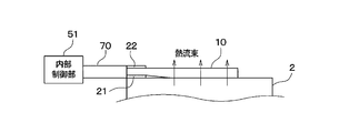
- FIG. 1 shows the overall configuration of the composite sensor 1 according to the first embodiment of the present invention.
- the composite sensor 1 includes a heat flux sensor 10, a first temperature sensor 21, a second temperature sensor 22, an internal control unit 51, and a wiring member 70.
- the composite sensor 1 of the present embodiment has a sensing unit including a heat flux sensor 10, a first temperature sensor 21, and a second temperature sensor 22, and this sensing unit is the surface of the engine 2 of the vehicle shown in FIG. Is placed in contact with.
- the heat flux sensor 10 detects a heat flux that is one of the fluxes as the first physical quantity.
- the heat flux is the amount of heat that crosses the unit area per unit time, and the unit is W / m2.
- the heat flux sensor 10 of the present embodiment detects a heat flux that is generated inside the engine 2 of the vehicle and flows from the inside of the engine 2 to the outside, and a signal for specifying the heat flux is detected as an internal control unit 51. Output to.
- the first temperature sensor 21 and the second temperature sensor 22 are different types of sensors from the heat flux sensor 10, respectively, and detect temperature as a second physical quantity correlated with the heat flux detected by the heat flux sensor 10, A signal for specifying the temperature is output as a detection result.
- 1st temperature sensor 21 and 2nd temperature sensor 22 can be constituted using a thermocouple, a thermistor, etc., for example.
- the wiring member 70 is composed of an insulating substrate on which a conductive pattern is formed.
- the conductive pattern is formed on the insulating substrate so as to connect the heat flux sensor 10, the first temperature sensor 21, the second temperature sensor 22, and the internal control unit 51.
- the internal control unit 51 is configured as a computer including a CPU (central processing unit), an input / output interface (I / O), etc. (not shown), and the internal control unit 51 is a storage medium for storing various data.
- the CPU of the internal control unit 51 performs various processes according to the program stored in the memory 51a.
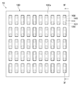
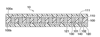
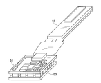
- the configuration of the heat flux sensor 10 will be described. As shown in FIGS. 3 and 4, in the heat flux sensor 10, the insulating base material 100, the surface protection member 110, and the back surface protection member 120 are integrated, and the first and second interlayer connections are formed inside the integrated body. The members 130 and 140 are alternately connected in series.
- the insulating base material 100, the surface protection member 110, and the back surface protection member 120 are in the form of a film and are made of a flexible resin material such as a thermoplastic resin.
- the insulating base material 100 is formed with a plurality of first and second via holes 101 and 102 penetrating in the thickness direction.
- First and second interlayer connection members 130 and 140 made of different thermoelectric materials such as metals and semiconductors are embedded in the first and second via holes.
- One connection portion of the first and second interlayer connection members 130 and 140 is constituted by the surface conductor pattern 111 disposed on the surface 100 a of the insulating base material 100.
- the other connection portion of the first and second interlayer connection members 130 and 140 is constituted by the back surface conductor pattern 121 arranged on the back surface 100b of the insulating base material 100.
- thermoelectromotive force is generated in the first and second interlayer connection members 130 and 140 by the Seebeck effect.
- the heat flux sensor 10 outputs this thermoelectromotive force (for example, voltage) as a sensor signal.
- the first temperature sensor 21 is disposed on the upstream surface of the heat flux passing through the insulating base material 100 of the heat flux sensor 10 from the vehicle engine 2
- the second temperature sensor 22 is The heat flux sensor 10 is disposed on the downstream surface of the heat flux passing through the insulating substrate 100 of the heat flux sensor 10 from the engine 2 of the vehicle.
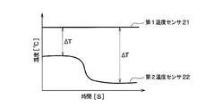
- thermoelectromotive force according to the temperature difference ⁇ T between the temperature detected by the first temperature sensor 21 and the temperature detected by the second temperature sensor 22 is the first and second interlayer connecting members 130 and 140 of the heat flux sensor 10. Will occur in between.
- FIG. 5 is a block diagram of the composite sensor 1 of the present embodiment.
- the composite sensor 1 of the present embodiment includes a heat flux sensor 10, a first temperature sensor 21, a second temperature sensor 22, an internal control unit 51, and a communication unit 60.
- the communication unit 60 performs wireless communication between the internal control unit 51 and the external control unit 52.
- the communication unit 60 of the present embodiment wirelessly transmits the data input from the internal control unit 51 to the external control unit 52 according to a predetermined communication format.
- the external control unit 52 accumulates and stores data received from the internal control unit 51 via the communication unit 60 in a storage medium (shown as a memory 52a), and displays information based on the data accumulated and stored in the storage medium (display unit ( A process of displaying on the screen (not shown) is performed.
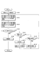
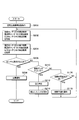
- FIG. 6 shows a flowchart of processing executed in the internal control unit 51.
- the internal control unit 51 periodically performs the process shown in FIG. Note that each control step in the flowchart of each drawing constitutes various function realizing means of the internal control unit 51.
- step S100 the internal control unit 51 instructs the engine start of the vehicle. Specifically, the internal control unit 51 controls the ignition switch so as to turn on the ignition switch of the vehicle.
- step S102 the internal control unit 51 acquires the detection result of the first temperature sensor 21, the detection result of the second temperature sensor 22, and the detection result of the heat flux sensor 10. Specifically, the temperature is specified based on the signal output from the first temperature sensor 21, the temperature is specified based on the signal output from the second temperature sensor 22, and further output from the heat flux sensor 10. The heat flux is identified based on the received signal.
- step S104 the internal control unit 51 uses the detection result of the first temperature sensor 21, the detection result of the second temperature sensor 22 and the detection result of the heat flux sensor 10 acquired in step S102 as the internal control unit 51. Is stored in the memory 51a, which is a storage medium.
- the temperature specified based on the signal output from the first temperature sensor 21, the temperature specified based on the signal output from the second temperature sensor 22, and the heat flux output from the heat flux sensor 10 It is stored in the memory 51a.
- the memory 51a stores not only the latest value but also statistical data for a certain amount of data in the memory 51a.
- the data stored in the memory 51a is used when setting a preventive maintenance threshold Mth described later.
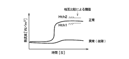
- step S106 the internal control unit 51 determines whether or not there is an abnormality in the sensor. Specifically, the difference D1 between the temperature detected by the first temperature sensor 21 and the temperature detected by the second temperature sensor 22 is calculated, and the difference D1 and the output value of the heat flux sensor 10 are compared with each other. It is determined whether there is an abnormality in the sensor.
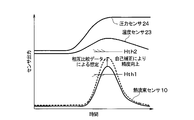
- the heat flux detected by the normal heat flux sensor 10 falls within the standard range in which the lower limit threshold value is Hth1 and the upper limit threshold value is Hth2, as indicated by “normal” in FIG.
- the heat flux detected by the normal heat flux sensor 10 falls within the standard range. Enter.
- a failure occurs when the heat flux detected by the heat flux sensor 10 does not fall within the standard range where the lower limit threshold is Hth1 and the upper limit threshold is Hth2. Is determined.
- the internal control unit 51 detects the temperature detected by the first temperature sensor 21 in step S108.
- the fact that there is a failure is wirelessly transmitted to the external control unit 52, and this process ends.
- the external control unit 52 when the external control unit 52 receives data from the internal control unit 51, the external control unit 52 performs processing for accumulating and storing the received data in the memory 52a. Further, the external control unit 52 reads out the data stored and stored in the storage medium in response to a user operation from the memory 52a, displays it in a graph on the display unit, and displays a message indicating a failure.
- the temperature difference ⁇ T between the first temperature sensor 21 and the second temperature sensor 22 changes with the passage of time. At this time, as indicated by “normal” in FIG. In addition, it is assumed that the heat flux detected by the heat flux sensor 10 falls within the standard range where the lower limit threshold is Hth1 and the upper limit threshold is Hth2.
- step S106 the determination in step S106 is NO, and then in step S110, the internal control unit 51 determines whether or not the accuracy deviation is large. Specifically, the internal control unit 51 determines that the difference between the heat flux detected by the heat flux sensor 10 and the lower limit threshold Hth1t is less than the reference value, or the difference between the heat flux detected by the heat flux sensor 10 and the upper limit threshold Hth2. Is determined to be less than the reference value.
- the difference between the heat flux detected by the heat flux sensor 10 and the lower limit threshold Hth1t is less than the reference value, or the difference between the heat flux detected by the heat flux sensor 10 and the upper limit threshold Hth2 is less than the reference value.
- the internal control unit 51 performs self-correction in step S112.
- FIG. 9 shows a state where the difference between the heat flux detected by the heat flux sensor 10 and the lower limit threshold Hth1t is less than the reference value.
- the value of the heat flux detected by the heat flux sensor 10 is multiplied by a predetermined coefficient, and this multiplied value is used as the value of the heat flux detected by the heat flux sensor 10. In this way, self-correction is performed.
- step S ⁇ b> 114 the internal control unit 51 includes the temperature detected by the first temperature sensor 21, the temperature detected by the second temperature sensor 22, and the value of the heat flux detected by the heat flux sensor 10.
- the fact that the detection result of the heat flux sensor 10 has been corrected is wirelessly transmitted to the external control unit 52, and the process flow returns to step S102.
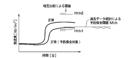
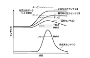
- the internal control unit 51 determines in step S116 whether or not there is a high possibility of failure of the heat flux sensor 10. Specifically, as shown in FIG. 10, the internal control unit 51 sets the preventive maintenance threshold value Mth based on the statistical data of the heat flux previously stored in the memory 51a in step S104, and this time, the heat flux It is determined whether the value of the heat flux detected by the sensor 10 is greater than or equal to the preventive maintenance threshold Mth.
- the preventive maintenance threshold value Mth can be set to a value obtained by multiplying the average value of past heat fluxes stored in the memory 51a by a certain constant (for example, 10%), for example.
- the internal control unit 51 detects the detection result of the heat flux sensor 10, the detection results of the first and second temperature sensors 21, 22, and the heat flux stored in the memory 51a in the past.
- a failure prediction unit 51d that compares the detection results of the sensor 10 and the detection results of the first and second temperature sensors 21 and 22 to predict failure of the heat flux sensor 10 and the first and second temperature sensors 21 and 22 is provided. Yes.
- step S116 When it is determined in step S116 that the possibility of failure of the heat flux sensor 10 is high, the internal control unit 51 detects the temperature detected by the first temperature sensor 21 and the second temperature sensor 22 in step S118. Along with the measured temperature and each value of the heat flux detected by the heat flux sensor 10, the fact that there is a high possibility that the heat flux sensor 10 will fail is wirelessly transmitted to the external control unit 52, and the process flow is step S102. Return to.
- the internal control unit 51 performs failure diagnosis of at least one of the first sensor and the second sensor by comparing the detection result of the first sensor and the detection result of the second sensor. It is possible to detect a sensor failure when some of the sensors fail.
- the first sensor may be the heat flux sensor 10 that detects the heat flux as the first physical quantity.
- a plurality of first and second via holes 101 and 102 penetrating in the thickness direction are formed in an insulating base material 100 made of a thermoplastic resin, and different metals are formed in the first and second via holes.
- the first and second interlayer connection members 130 and 140 formed in (1) are embedded, and the first and second interlayer connection members 130 and 140 are alternately connected in series.
- thermoelectromotive force may generate
- the composite sensor 1 includes first and second temperature sensors 21 and 22 that detect a temperature as a second sensor that detects a second physical quantity that is the same as the first physical quantity or correlates with the first physical quantity. ing.
- the internal control unit 51 compares the change in the heat flux detected by the heat flux sensor 10 with the temperature change detected by the first and second temperature sensors 21 and 22 to thereby compare the heat flux sensor 10 and the first heat flux sensor 10. Failure diagnosis of at least one of the first and second temperature sensors 21 and 22 can be performed.
- the composite sensor 1 includes a first temperature sensor 21 disposed on the upstream surface of the heat flux passing through the insulating base material 100 of the heat flux sensor 10 and an insulating base material of the heat flux sensor 10 as the second sensor. And a second temperature sensor 22 disposed on the downstream surface of the heat flux passing through 100. Then, the internal control unit 51 compares the change in the heat flux detected by the heat flux sensor 10 with the temperature difference between the temperature detected by the first temperature sensor 21 and the temperature detected by the second temperature sensor 22. By doing so, failure diagnosis of at least one of the heat flux sensor 10, the first temperature sensor 21, and the second temperature sensor 22 can be performed.
- the internal control unit 51 determines that the failure diagnosis result of at least one of the heat flux sensor 10 and the first and second temperature sensors 21 and 22 is not a failure
- the detection result of the heat flux sensor 10 and A correction unit 51b that compares the detection results of the first and second temperature sensors 21 and 22 and corrects at least one of the detection results of the heat flux sensor 10 and the detection results of the first and second temperature sensors 21 and 22 (step) S112).
- the detection result of the heat flux sensor 10 is self-corrected in advance. Is possible.
- the internal control unit 51 includes a storage control unit 51c that stores the detection result of the heat flux sensor 10 and the detection results of the first and second temperature sensors 21 and 22 in the memory 51a.
- the internal control unit 51 also detects the detection result of the heat flux sensor 10, the detection results of the first and second temperature sensors 21, 22, the detection result of the heat flux sensor 10 previously stored in the memory 51a, and the first,
- a failure prediction unit 51d (step S116) that compares the detection results of the second temperature sensors 21 and 22 and predicts failure of the heat flux sensor 10 and the first and second temperature sensors 21 and 22 is provided. Thereby, it is possible to perform preventive maintenance such as exchanging the composite sensor in advance before the composite sensor 1 breaks down.
- the CPU of the internal control unit 51 executes various functions related to the correction unit 51b, the storage control unit 51c, and the failure prediction unit 51d by executing various programs stored in the memory 51a.
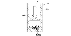
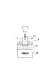
- FIG. 11 shows a state in which the composite sensor according to the second embodiment of the present invention is provided in the air compression mechanism 3.
- the air compression mechanism 3 includes a bottomed cylindrical cylinder 90 and a piston 91.
- the piston 91 reciprocates in the cylinder 90 as the electric motor rotates.
- the pressure of the air in the cylinder 90 is changed by the reciprocating motion of the piston 91.
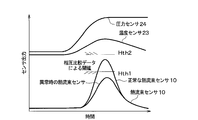
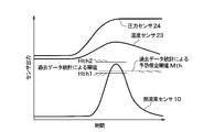
- the composite sensor according to the present embodiment has a sensing unit including a pressure sensor 24, a heat flux sensor 10, and a temperature sensor 23, and the sensing unit is disposed so as to come into contact with the bottom surface of the cylinder 90 shown in FIG. .
- the heat flux sensor 10 and the temperature sensor 23 are arranged side by side so as to be in contact with the bottom surface of the cylinder 90, and the pressure sensor 24 is sandwiched between the bottom surface of the cylinder 90 and the heat flux sensor 10 and the temperature sensor 23. Has been placed. Therefore, the pressure sensor 24 is disposed so as to be in contact with the air in the cylinder 90.
- the piston 91 reciprocates in the cylinder 90, so that the temperature of air in the cylinder 90 rises.
- a heat flux that flows from the inside of the cylinder 90 to the surface of the cylinder 90 is generated due to the temperature rise of the air in the cylinder 90.
- the heat flux sensor 10 detects a heat flux that is one of the fluxes as the first physical quantity.
- the pressure sensor 24 detects the pressure of the air in the cylinder 90 as a second physical quantity correlated with the heat flux detected by the heat flux sensor 10 and outputs a signal for specifying the pressure as a detection result.
- the temperature sensor 23 detects the temperature of the air in the cylinder 90 as a second physical quantity that correlates with the heat flux detected by the heat flux sensor 10, and outputs a signal for specifying the temperature of the air in the cylinder 90. Output as detection result.
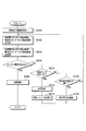
- FIG. 13 shows a flowchart of processing executed in the internal control unit 51.
- the internal control unit 51 periodically performs the process shown in FIG. Note that each control step in the flowchart of each drawing constitutes various function realizing means of the internal control unit 51.
- step S200 the internal control unit 51 instructs the start of the air compression mechanism 3. Specifically, the internal control unit 51 starts power feeding to the electric motor so as to operate an electric motor (not shown) of the air compression mechanism 3.
- step S202 the internal control unit 51 acquires the detection result of the temperature sensor 23, the detection result of the heat flux sensor 10, and the detection result of the pressure sensor 24. Specifically, the internal control unit 51 identifies the temperature of the air in the cylinder 90 based on the signal output from the temperature sensor 23, and from the cylinder 90 to the cylinder based on the signal output from the heat flux sensor 10. The heat flux flowing to the surface of 90 is specified, and the pressure of air in the cylinder 90 is specified based on the signal output from the pressure sensor 24.
- step S204 the internal control unit 51 stores the detection result of the temperature sensor 23, the detection result of the heat flux sensor 10 and the detection result of the pressure sensor 24 acquired in step S202 in the memory 51a. Specifically, the internal control unit 51 detects the temperature of the air in the cylinder 90 specified based on the signal output from the temperature sensor 23 and the inside of the cylinder 90 specified based on the signal output from the heat flux sensor 10. Based on the heat flux flowing to the surface of the cylinder 90 and the signal output from the pressure sensor 24, the pressure of the air in the cylinder 90 is stored in the memory 51a.
- the memory 51a stores not only the latest value but also statistical data for a certain amount of data in the memory 51a.
- the data stored in the memory 51a is used when setting a preventive maintenance threshold Mth described later.
- step S206 the internal control unit 51 determines whether or not there is an abnormality in the sensor.
- the temperature sensor 23 and the pressure sensor 24 are normal among the temperature sensor 23, the heat flux sensor 10, and the pressure sensor 24.
- a standard range in which the lower limit threshold of the heat flux sensor 10 is Hth1 and the upper limit threshold is Hth2 is determined based on the detection result of the temperature sensor 23 and the detection result of the pressure sensor 24. Then, it is determined whether or not the heat flux sensor 10 has failed based on whether or not the value of the heat flux detected by the heat flux sensor 10 falls within the standard range where the lower limit threshold is Hth1 and the upper limit threshold is Hth2. To do.
- the output value of the heat flux sensor 10 falls within a standard range in which the lower limit threshold is Hth1 and the upper limit threshold is Hth2, and in the case of an abnormal heat flux sensor 10.
- the output value of the heat flux sensor 10 does not fall within the standard range where the lower threshold is Hth1 and the upper threshold is Hth2.
- the appropriate ranges of the heat flux sensor 10 and the pressure sensor 24 are determined from the detection result of the temperature sensor 23.
- the lower limit threshold of the appropriate range of the heat flux sensor 10 is Hth1
- the upper limit threshold is Hth2
- the lower limit threshold of the appropriate range of the pressure sensor 24 is Pth1
- the upper limit threshold is Pth2.
- the heat flux sensor 10 is within the appropriate range, it is determined that the heat flux sensor 10 is normal. If the output value of the heat flux sensor 10 is outside the appropriate range, the heat flux sensor 10 is normal. Is determined.
- the pressure sensor 24 is determined to be normal, and if the output value of the pressure sensor 24 is outside the proper range, the pressure sensor 24 is determined to be abnormal.
- step S208 the internal control unit 51 determines the temperature of the air in the cylinder 90 detected by the temperature sensor 23 and the heat flux detected by the heat flux sensor 10. Along with the value and the pressure of the air in the cylinder 90 detected by the pressure sensor 24, the fact that there is a failure is wirelessly transmitted to the external control unit 52, and this process ends.
- step S210 the internal control unit 51 determines whether or not the accuracy deviation is large. Specifically, the internal control unit 51 determines that the difference between the heat flux detected by the heat flux sensor 10 and the lower limit threshold Hth1t is less than the reference value, or the difference between the heat flux detected by the heat flux sensor 10 and the upper limit threshold Hth2. Is determined to be less than the reference value.
- the internal control unit 51 determines that the difference between the heat flux detected by the heat flux sensor 10 and the lower limit threshold Hth1t is less than the reference value, or the difference between the heat flux detected by the heat flux sensor 10 and the upper limit threshold Hth2 is the reference. If it is less than the value, self correction is performed in step S212.
- FIG. 16 shows a state where the difference between the heat flux detected by the heat flux sensor 10 and the lower limit threshold Hth1t is less than the reference value.
- the value of the heat flux detected by the heat flux sensor 10 is multiplied by a predetermined coefficient, and this multiplied value is used as the value of the heat flux detected by the heat flux sensor 10. In this way, self-correction is performed.
- step S214 the internal control unit 51 determines the surface of the cylinder 90 from within the cylinder 90 specified based on the temperature of the air in the cylinder 90 detected by the temperature sensor 23 and the signal output from the heat flux sensor 10.
- the value of the heat flux flowing into the cylinder, and the correction result of the detection result of the heat flux sensor 10 together with the self-corrected value and the pressure of the air in the cylinder 90 specified based on the signal output from the pressure sensor 24 Wireless transmission is performed to the external control unit 52, and the process flow returns to step S202.
- the internal control unit 51 determines in step S116 whether or not there is a high possibility of failure of the heat flux sensor 10. Specifically, as shown in FIG. 17, the internal control unit 51 sets the preventive maintenance threshold Mth based on the statistical data of the heat flux previously stored in the memory 51a in step S204, and this time the heat flux It is determined whether the value of the heat flux detected by the sensor 10 is greater than or equal to the preventive maintenance threshold Mth.
- the preventive maintenance threshold value Mth can be set to a value obtained by multiplying the average value of past heat fluxes stored in the memory 51a by a certain constant (for example, 10%), for example.
- step S116 if it is determined in step S116 that the possibility of failure of the heat flux sensor 10 is high, the internal control unit 51 then detects the temperature detected by the temperature sensor 23 and the pressure sensor 24 in step S118. Along with the pressure and the value of the heat flux detected by the heat flux sensor 10, the fact that the possibility that the heat flux sensor 10 is broken is wirelessly transmitted to the external control unit 52, and the process returns to step S202. If it is determined that the possibility of failure of the heat flux sensor 10 is not high, the process flow returns to step S202.
- the second sensor includes a temperature sensor 23 that detects temperature as a physical quantity that correlates with the first physical quantity, and a pressure sensor 24 that detects pressure as a physical quantity that correlates with the first physical quantity.
- the internal control unit 51 compares at least one of the first sensor and the second sensor by comparing the change in the heat flux detected by the heat flux sensor with the detection result of the temperature sensor and the detection result of the pressure sensor. Fault diagnosis can be performed.
- the cutting machine 4 is a processing apparatus for making a hole in a workpiece 94 that is a workpiece.
- the cutting machine 4 includes a chuck 95 for fixing a workpiece 94 that is a workpiece, and a drill 93 that is rotated by a motor (not shown).
- the drill 93 is a cutting tool used for cutting.
- the work 94 is fixed on the chuck 95.
- a work 94 is installed under the drill 93.
- Examples of the work 94 include a metal block.
- the user operates a handle (not shown) downward while the drill 31 is rotated. As a result, the rotated drill 93 moves downward while machining the workpiece 94. In this way, the workpiece 94 is drilled.
- thermal energy increases due to friction between the drill 93 and the workpiece 94, and a heat flux that flows from the contact portion between the drill 93 and the workpiece 94 to the surface of the workpiece 94 is generated.
- a heat flux has a correlation with the cutting resistance at the time of cutting.
- the composite sensor of the present embodiment includes a heat flux sensor 10 that detects a heat flux and a cutting dynamometer 25 that is a cutting resistance detector that detects a cutting resistance at the time of cutting.
- the heat flux sensor 10 is fixed to the surface of the workpiece 94.
- the heat flux sensor 10 detects a heat flux flowing from the contact portion between the drill 93 and the workpiece 94 to the surface of the workpiece 94 as a first physical quantity, and outputs a signal for specifying the heat flux to the internal control unit 51. To do.
- the cutting dynamometer 25 is disposed below the chuck 95 that fixes the workpiece 94.
- the cutting dynamometer 25 detects a cutting resistance at the time of cutting as a second physical quantity correlated with the first physical quantity, and outputs a signal indicating the detected cutting resistance to the internal control unit 51.
- FIG. 19 shows a flowchart of processing executed in the internal control unit 51.
- the internal control unit 51 periodically performs the process shown in FIG.
- the internal control unit 51 performs the process shown in FIG.
- the internal control unit 51 instructs to start the cutting machine 4 in step S300.
- power supply to the motor is started so as to operate a motor (not shown) that rotates the drill 93.
- the internal control unit 51 acquires the detection result of the cutting dynamometer 25 and the detection result of the heat flux sensor 10 in step S302. Specifically, the internal control unit 51 specifies the cutting resistance value based on the signal output from the cutting dynamometer 25 and specifies the heat flux based on the signal output from the heat flux sensor 10.
- step S304 the internal control unit 51 stores the detection result of the cutting dynamometer 25 and the detection result of the heat flux sensor 10 acquired in step S302 in the memory 51a. Specifically, the temperature specified based on the signal output from the cutting dynamometer 25 and the heat flux output from the heat flux sensor 10 are stored in the memory 51a.
- the memory 51a stores not only the latest value but also statistical data for a certain amount of data in the memory 51a.
- the data stored in the memory 51a is used when setting a preventive maintenance threshold Mth described later.
- step S306 the internal control unit 51 determines whether or not there is an abnormality in the sensor. More specifically, the cutting resistance detected by the cutting dynamometer 25 and the output value of the heat flux sensor 10 are compared with each other to determine whether or not the sensor is abnormal.
- a standard range is set in which the lower threshold is Hth1 and the upper threshold is Hth2. Then, it is determined whether or not the output value of the heat flux sensor 10 is within the standard range where the lower limit threshold is Hth1 and the upper limit threshold is Hth2.
- the output value of the normal heat flux sensor 10 falls within the standard range where the lower threshold is Hth1 and the upper threshold is Hth2. However, if the output value of the heat flux sensor 10 at the time of abnormality does not fall within the standard range where the lower limit threshold is Hth1 and the upper limit threshold is Hth2, it is determined that there is a failure.
- the internal control unit 51 determines the cutting resistance detected by the cutting dynamometer 25 in step S308. At the same time, together with the value of the heat flux detected by the heat flux sensor 10, the fact that there is a failure is wirelessly transmitted to the external control unit 52, and this process is terminated.
- step S306 determines whether the accuracy deviation is large.
- the internal control unit 51 determines that the difference between the heat flux detected by the heat flux sensor 10 and the lower limit threshold Hth1t is less than the reference value, or the difference between the heat flux detected by the heat flux sensor 10 and the upper limit threshold Hth2. Is determined to be less than the reference value.
- the difference between the heat flux detected by the heat flux sensor 10 and the lower limit threshold Hth1t is less than the reference value, or the difference between the heat flux detected by the heat flux sensor 10 and the upper limit threshold Hth2 is less than the reference value.
- the internal control unit 51 performs self-correction in step S312.
- FIG. 9 shows a state where the difference between the heat flux detected by the heat flux sensor 10 and the lower limit threshold Hth1t is less than the reference value.
- the value of the heat flux detected by the heat flux sensor 10 is multiplied by a predetermined coefficient, and this multiplied value is used as the value of the heat flux detected by the heat flux sensor 10. In this way, self-correction is performed.
- step S314 the internal control unit 51 includes the cutting resistance detected by the cutting dynamometer 25, the value of the heat flux detected by the heat flux sensor 10, and the self-corrected value.
- the fact that the detection result is corrected is wirelessly transmitted to the external control unit 52, and the process flow returns to step S302.
- step S116 the internal control unit 51 determines whether or not there is a high possibility of failure of the heat flux sensor 10, and the heat flux sensor 10 If the possibility of failure is high, notification of failure prediction is made in step S118, and if the possibility of failure of the heat flux sensor 10 is not high, the process flow returns to step S302.
- the second sensor is a cutting dynamometer 25 which is a cutting resistance detector that detects a cutting resistance in the cutting machine as the second physical quantity.
- the internal control unit 51 compares at least the first sensor and the second sensor by comparing the change in the heat flux detected by the heat flux sensor 10 with the change in the cutting resistance detected by the cutting dynamometer 25. One failure diagnosis can be performed.
- FIG. 21 shows the overall configuration of the composite sensor according to the fourth embodiment of the present invention.
- the composite sensor of the present embodiment includes a power generation unit 53 having a Peltier element.
- the Peltier element has a structure in which two kinds of metals are joined. When a direct current is passed between the two kinds of metals, the Peltier element has the property that heat is transferred from one metal to the other. .
- the Peltier element can also generate thermal power when a temperature difference is given between two types of metals. This action is called Seebeck effect.
- the power generation unit 53 is a thermoelectric conversion module that generates power by the Seebeck effect of the Peltier element.
- the composite sensor of this embodiment is different from the composite sensor of the first embodiment in that a Peltier element is incorporated as a thermoelectric conversion module.
- the composite sensor of the present embodiment includes a power generation unit 53 that generates power by the Seebeck effect of the Peltier element.
- the heat flux sensor 10, the first and second temperature sensors 21, 22 and the internal control unit 51 generate power. It is configured to operate with electric power.
- the same effect as that of the first embodiment can be obtained, and it is not necessary to provide a power source or a battery for supplying power for driving the composite sensor. Is not limited.
- the heat flux specified by the internal control unit 51 based on the signal output from the heat flux sensor 10 and the first and second temperature sensors 21 and 22 are used.
- Each temperature specified based on the output signal is configured to be transmitted to the external control unit 52, but the external control unit 52 specifies the heat flux based on the signal output from the heat flux sensor 10, Furthermore, the temperature may be specified based on signals output from the first and second temperature sensors 21 and 22.
- the communication unit 60 for performing wireless communication between the internal control unit 51 and the external control unit 52 is provided, and the internal control unit 51 via the communication unit 60 is provided.
- the data is wirelessly transmitted to the external control unit 52, the data may be transmitted by wire.
- the power generation unit includes a power generation unit that uses a Peltier element, and the first sensor, the second sensor, and the internal control unit 51 are configured to be operated by the power generated by the power generation unit.
- the internal control unit 51 may be configured to operate with the power generated by these power generation units.
- control unit compares the detection result of the first sensor and the detection result of the second sensor with each other. Since at least one failure diagnosis with the second sensor is performed, it is possible to detect the failure of the sensor when some of the sensors fail.
- the first sensor can be the heat flux sensor 10 that detects the heat flux as the first physical quantity.
- the heat flux sensor 10 includes a plurality of first, through the insulating base material 100 made of a thermoplastic resin in the thickness direction. Second via holes 101 and 102 are formed, and first and second interlayer connection members 130 and 140 formed of different metals are embedded in the first and second via holes, and the first and second interlayers are buried. Connection members 130 and 140 are alternately connected in series.
- thermoelectromotive force may generate
- the second sensor is a temperature sensor that detects a temperature as a physical quantity correlated with the first physical quantity.
- the control unit performs failure diagnosis of at least one of the first sensor and the second sensor by comparing the change in the heat flux detected by the first sensor and the temperature change detected by the second sensor. be able to.
- the second sensor is disposed on the upstream surface of the heat flux passing through the insulating base of the heat flux sensor.
- 1 temperature sensor 21, and the 2nd temperature sensor 22 arrange
- the control unit compares the change in the heat flux detected by the first sensor with the temperature difference between the temperature detected by the first temperature sensor and the temperature detected by the second temperature sensor, thereby comparing the heat flux. Failure diagnosis of at least one of the sensor, the first temperature sensor, and the second temperature sensor can be performed.
- a correction unit (51b, steps S112, S212, S312) that compares the detection result of the first sensor and the detection result of the second sensor and corrects at least one of the detection result of the first sensor and the detection result of the second sensor; It has. Accordingly, at least one of the detection result of the first sensor and the detection result of the second sensor can be corrected in advance before it is determined that at least one of the first sensor and the second sensor is out of order.
- the second sensor includes a temperature sensor that detects a temperature as a physical quantity correlated with the first physical quantity, and the first physical quantity A pressure sensor that detects pressure as a correlated physical quantity. Further, the control unit compares the change in the heat flux detected by the heat flux sensor with the detection result of the temperature sensor and the detection result of the pressure sensor, thereby diagnosing a failure of at least one of the first sensor and the second sensor. It can be performed.
- the second sensor is a cutting resistance detection unit that detects cutting resistance in a cutting machine as the second physical quantity. it can. Further, the control unit compares at least one of the failure of the first sensor and the second sensor by comparing the change of the heat flux detected by the heat flux sensor with the change of the cutting resistance detected by the cutting resistance detection unit. Diagnosis can be made.
- the control unit stores the detection result of the first sensor and the detection result of the second sensor in the storage medium (51a).
- the control unit includes a control unit (51c, S104, S204, S304).
- the control unit further detects the detection result of the first sensor and the detection result of the second sensor, and the detection of the first sensor stored in the storage medium in the past.
- a failure prediction unit (51d, step S116) is provided that compares the result and the detection result of the second sensor to predict failure of the first sensor and the second sensor. Thereby, failure prediction of the first sensor and the second sensor can be performed.
- the control unit includes a communication unit for communication. Furthermore, the control unit includes an internal control unit that acquires the detection result of the first sensor and the detection result of the second sensor, and transmits the detection result of the first sensor and the detection result of the second sensor via the communication unit. Yes. Further, the control unit performs an external control for performing failure diagnosis of at least one of the first sensor and the second sensor by comparing the detection result of the first sensor and the detection result of the second sensor transmitted from the internal control unit. And a section. Thereby, failure diagnosis of at least one of the first sensor and the second sensor can be performed.
- the communication unit performs wireless communication
- the internal control unit performs the first sensor and the first communication by wireless communication via the communication unit. Since the detection results of the two sensors are transmitted to the external control unit, the installation location of the composite sensor is not limited.
- the power generation unit that generates power is provided, and the first sensor, the second sensor, and the control unit are based on the power generated by the power generation unit. Since it operates, the installation location is not limited.
Landscapes
- Physics & Mathematics (AREA)
- General Physics & Mathematics (AREA)
- Chemical & Material Sciences (AREA)
- Engineering & Computer Science (AREA)
- Combustion & Propulsion (AREA)
- Spectroscopy & Molecular Physics (AREA)
- Measuring Temperature Or Quantity Of Heat (AREA)
- Testing Or Calibration Of Command Recording Devices (AREA)
- Testing Of Devices, Machine Parts, Or Other Structures Thereof (AREA)
Priority Applications (4)
| Application Number | Priority Date | Filing Date | Title |
|---|---|---|---|
| CN201680060160.2A CN108139280A (zh) | 2015-10-14 | 2016-10-13 | 复合传感器 |
| US15/768,488 US20180306611A1 (en) | 2015-10-14 | 2016-10-13 | Composite sensor |
| EP16855450.9A EP3361227A4 (en) | 2015-10-14 | 2016-10-13 | Composite sensor |
| KR1020187010313A KR20180053354A (ko) | 2015-10-14 | 2016-10-13 | 복합 센서 |
Applications Claiming Priority (2)
| Application Number | Priority Date | Filing Date | Title |
|---|---|---|---|
| JP2015203211A JP2017075844A (ja) | 2015-10-14 | 2015-10-14 | 複合センサ |
| JP2015-203211 | 2015-10-14 |
Publications (1)
| Publication Number | Publication Date |
|---|---|
| WO2017065197A1 true WO2017065197A1 (ja) | 2017-04-20 |
Family
ID=58517265
Family Applications (1)
| Application Number | Title | Priority Date | Filing Date |
|---|---|---|---|
| PCT/JP2016/080316 Ceased WO2017065197A1 (ja) | 2015-10-14 | 2016-10-13 | 複合センサ |
Country Status (7)
| Country | Link |
|---|---|
| US (1) | US20180306611A1 (cg-RX-API-DMAC7.html) |
| EP (1) | EP3361227A4 (cg-RX-API-DMAC7.html) |
| JP (1) | JP2017075844A (cg-RX-API-DMAC7.html) |
| KR (1) | KR20180053354A (cg-RX-API-DMAC7.html) |
| CN (1) | CN108139280A (cg-RX-API-DMAC7.html) |
| TW (1) | TWI647432B (cg-RX-API-DMAC7.html) |
| WO (1) | WO2017065197A1 (cg-RX-API-DMAC7.html) |
Cited By (1)
| Publication number | Priority date | Publication date | Assignee | Title |
|---|---|---|---|---|
| CN111757823A (zh) * | 2018-03-21 | 2020-10-09 | 罗伯特·博世有限公司 | 用于车辆的传感器组件和用于监控传感器的方法 |
Families Citing this family (11)
| Publication number | Priority date | Publication date | Assignee | Title |
|---|---|---|---|---|
| KR101922105B1 (ko) * | 2017-07-06 | 2018-11-26 | 주식회사 코아칩스 | 무전원 무선 센서를 이용한 온도 측정 시스템 및 그에 의한 온도 측정 방법 |
| JP7087376B2 (ja) * | 2017-12-21 | 2022-06-21 | 株式会社デンソー | 熱交換器の異常検出装置 |
| JP6981336B2 (ja) * | 2018-03-26 | 2021-12-15 | 株式会社デンソー | 熱流測定装置およびその製造方法 |
| CN109654662B (zh) * | 2018-11-01 | 2020-05-01 | 珠海格力电器股份有限公司 | 检测元件控制方法、装置及空调机组 |
| DE102019108564A1 (de) * | 2019-04-02 | 2020-10-08 | Endress+Hauser SE+Co. KG | Zusatzmodul für ein Feldgerät |
| CN111024269B (zh) * | 2019-12-25 | 2020-12-08 | 中国计量大学 | 一种测量沿壁面热流的平面型热流传感器及其标定方法 |
| TWI770496B (zh) * | 2020-04-20 | 2022-07-11 | 達明機器人股份有限公司 | 機器人感測器的檢知方法 |
| JP7780143B2 (ja) * | 2021-11-09 | 2025-12-04 | 株式会社Eサーモジェンテック | 生体の深部体温測定システム |
| CN114708718A (zh) * | 2022-06-07 | 2022-07-05 | 东方电气风电股份有限公司 | 风力发电机组温度集群管控方法、装置、设备及介质 |
| JP7846363B2 (ja) * | 2022-06-10 | 2026-04-15 | 株式会社デンソーウェーブ | 空調用コントローラのセンサ検査装置、センサ検査方法 |
| CN116534240A (zh) * | 2023-06-16 | 2023-08-04 | 天津天航智远科技有限公司 | 一种系留飞艇压力控制系统及其压力控制方法 |
Citations (4)
| Publication number | Priority date | Publication date | Assignee | Title |
|---|---|---|---|---|
| JP2006350707A (ja) * | 2005-06-16 | 2006-12-28 | Hitachi Ltd | 検出手段の故障診断装置 |
| JP2012018045A (ja) * | 2010-07-07 | 2012-01-26 | Yamatake Corp | センサ異常診断装置及びセンサシステム |
| JP2012215403A (ja) * | 2011-03-31 | 2012-11-08 | Panasonic Corp | センサ装置 |
| JP2015077658A (ja) * | 2013-10-17 | 2015-04-23 | 株式会社神戸製鋼所 | 状態計測装置及び状態計測システム |
Family Cites Families (18)
| Publication number | Priority date | Publication date | Assignee | Title |
|---|---|---|---|---|
| JPH0640031B2 (ja) * | 1985-10-23 | 1994-05-25 | 英弘精機産業株式会社 | 熱流計センサ−及びその製法 |
| EP0524330B1 (de) * | 1991-07-22 | 1994-11-30 | Siemens Aktiengesellschaft | Verfahren zur Fehlererkennung und -lokalisierung von redundanten Signalgebern einer Automatisierungsanlage |
| JPH07180536A (ja) * | 1993-12-22 | 1995-07-18 | Nissan Motor Co Ltd | 触媒の劣化検出装置 |
| US6278051B1 (en) * | 1997-10-09 | 2001-08-21 | Vatell Corporation | Differential thermopile heat flux transducer |
| US6363330B1 (en) * | 1998-04-10 | 2002-03-26 | Satnam Singh Sampuran Alag | Thermocouple failure detection in power generation turbines |
| DE19840944B4 (de) * | 1998-09-08 | 2004-10-21 | Continental Teves Ag & Co. Ohg | Sicherheitsrelevantes System, insbesondere elektromechanisches Bremssystem |
| TW454872U (en) * | 1998-10-09 | 2001-09-11 | Chen Chao Wang | Infrared thermometer using unitary Bi-sensor and EEPROM |
| EP1078729A1 (de) * | 1999-08-25 | 2001-02-28 | Engel Maschinenbau Gesellschaft Mbh | Spritzgiessmaschine mit Mittel zum Nachweisen des Versagen eines Sensors |
| KR100690926B1 (ko) * | 2006-02-03 | 2007-03-09 | 삼성전자주식회사 | 마이크로 열유속 센서 어레이 |
| TWI434032B (zh) * | 2007-01-11 | 2014-04-11 | Marvell World Trade Ltd | 溫度感測系統 |
| DE102010012988B4 (de) * | 2010-03-26 | 2012-02-09 | Continental Automotive Gmbh | Verfahren zur Diagnose eines flüssigkeitsgekühlten Abgaskrümmers einer Brennkraftmaschine |
| KR20120046821A (ko) * | 2010-10-27 | 2012-05-11 | 파웰테크윈주식회사 | 범용 센서 자가 진단 장치 및 그 진단 방법 |
| JP5927865B2 (ja) * | 2011-11-25 | 2016-06-01 | 株式会社アドヴィックス | センサ故障診断機能を有する制御装置 |
| DE102011088296A1 (de) * | 2011-12-12 | 2013-06-13 | Robert Bosch Gmbh | Verfahren und Vorrichtung zur Dynamiküberwachung von Gas-Sensoren |
| US20140012511A1 (en) * | 2012-07-09 | 2014-01-09 | Dexcom, Inc. | Systems and methods for leveraging smartphone features in continuous glucose monitoring |
| US20140074380A1 (en) * | 2012-09-07 | 2014-03-13 | Continental Controls Corporation | Gas substitution control system and method for bi-fuel engine |
| TWM466413U (zh) * | 2013-06-20 | 2013-11-21 | Jin Sheng Technology Co Ltd | 具有迴路異常自我檢測之溫度感應電路 |
| TWM506964U (zh) * | 2015-03-03 | 2015-08-11 | Univ Nat Yunlin Sci & Tech | 感測裝置與陣列型感測器量測系統 |
-
2015
- 2015-10-14 JP JP2015203211A patent/JP2017075844A/ja active Pending
-
2016
- 2016-10-13 CN CN201680060160.2A patent/CN108139280A/zh active Pending
- 2016-10-13 US US15/768,488 patent/US20180306611A1/en not_active Abandoned
- 2016-10-13 KR KR1020187010313A patent/KR20180053354A/ko not_active Withdrawn
- 2016-10-13 WO PCT/JP2016/080316 patent/WO2017065197A1/ja not_active Ceased
- 2016-10-13 EP EP16855450.9A patent/EP3361227A4/en not_active Withdrawn
- 2016-10-14 TW TW105133268A patent/TWI647432B/zh not_active IP Right Cessation
Patent Citations (4)
| Publication number | Priority date | Publication date | Assignee | Title |
|---|---|---|---|---|
| JP2006350707A (ja) * | 2005-06-16 | 2006-12-28 | Hitachi Ltd | 検出手段の故障診断装置 |
| JP2012018045A (ja) * | 2010-07-07 | 2012-01-26 | Yamatake Corp | センサ異常診断装置及びセンサシステム |
| JP2012215403A (ja) * | 2011-03-31 | 2012-11-08 | Panasonic Corp | センサ装置 |
| JP2015077658A (ja) * | 2013-10-17 | 2015-04-23 | 株式会社神戸製鋼所 | 状態計測装置及び状態計測システム |
Cited By (1)
| Publication number | Priority date | Publication date | Assignee | Title |
|---|---|---|---|---|
| CN111757823A (zh) * | 2018-03-21 | 2020-10-09 | 罗伯特·博世有限公司 | 用于车辆的传感器组件和用于监控传感器的方法 |
Also Published As
| Publication number | Publication date |
|---|---|
| EP3361227A8 (en) | 2018-12-05 |
| TWI647432B (zh) | 2019-01-11 |
| JP2017075844A (ja) | 2017-04-20 |
| EP3361227A4 (en) | 2018-12-05 |
| TW201719128A (zh) | 2017-06-01 |
| KR20180053354A (ko) | 2018-05-21 |
| US20180306611A1 (en) | 2018-10-25 |
| EP3361227A1 (en) | 2018-08-15 |
| CN108139280A (zh) | 2018-06-08 |
Similar Documents
| Publication | Publication Date | Title |
|---|---|---|
| WO2017065197A1 (ja) | 複合センサ | |
| JP5987811B2 (ja) | 車両用の異常判定装置 | |
| US7330046B2 (en) | Circuits and methods for failure prediction of parallel MOSFETs | |
| US20190353605A1 (en) | Track pin communication system and method | |
| US10330514B2 (en) | Apparatus for monitoring a predetermined fill level | |
| JP2017075844A5 (cg-RX-API-DMAC7.html) | ||
| US10788379B2 (en) | Abnormality diagnosis apparatus | |
| CN101354586A (zh) | 监控系统和温度控制器 | |
| KR102260477B1 (ko) | 열화상을 이용한 회로기판의 고장 예지 시스템 | |
| JP2015032747A (ja) | 熱電変換素子の固定構造 | |
| EP2725336B1 (en) | Apparatus and Method To Detect Damage of a Component of a System | |
| JP6504125B2 (ja) | 亀裂監視装置及び異常予測装置 | |
| US20220333725A1 (en) | Hose system having means for detecting the temperature inside the hose | |
| JP7116215B2 (ja) | 防爆構造を有する電気回路 | |
| JP2009257863A (ja) | 電子回路基板 | |
| JP2019117154A (ja) | 歪み検出装置およびそれを用いた診断装置 | |
| JP2014138103A (ja) | 熱電発電ユニット | |
| JP6435503B2 (ja) | 発電装置 | |
| US20140149016A1 (en) | Conduit Degradation Detection System and Method | |
| JP2018189554A (ja) | 熱流式センサモジュール | |
| JP2018045293A (ja) | 絶縁型信号伝達装置、電子機器 | |
| KR20150104777A (ko) | 다이오드를 이용한 회로 상의 임계 온도 측정 장치 및 이를 포함하는 전장품 제어 시스템 | |
| JP6345930B2 (ja) | 半導体装置およびその設計方法 | |
| KR102046503B1 (ko) | 대기 환경 센서의 고장을 검출하기 위한 장치 | |
| JP6371634B2 (ja) | 表示装置 |
Legal Events
| Date | Code | Title | Description |
|---|---|---|---|
| 121 | Ep: the epo has been informed by wipo that ep was designated in this application |
Ref document number: 16855450 Country of ref document: EP Kind code of ref document: A1 |
|
| ENP | Entry into the national phase |
Ref document number: 20187010313 Country of ref document: KR Kind code of ref document: A |
|
| WWE | Wipo information: entry into national phase |
Ref document number: 15768488 Country of ref document: US |
|
| NENP | Non-entry into the national phase |
Ref country code: DE |
|
| WWE | Wipo information: entry into national phase |
Ref document number: 2016855450 Country of ref document: EP |