WO2017065092A1 - Information processing device - Google Patents
Information processing device Download PDFInfo
- Publication number
- WO2017065092A1 WO2017065092A1 PCT/JP2016/079855 JP2016079855W WO2017065092A1 WO 2017065092 A1 WO2017065092 A1 WO 2017065092A1 JP 2016079855 W JP2016079855 W JP 2016079855W WO 2017065092 A1 WO2017065092 A1 WO 2017065092A1
- Authority
- WO
- WIPO (PCT)
- Prior art keywords
- sound
- information processing
- processing apparatus
- unit
- sound collection
- Prior art date
Links
Images


Classifications
-
- H—ELECTRICITY
- H04—ELECTRIC COMMUNICATION TECHNIQUE
- H04M—TELEPHONIC COMMUNICATION
- H04M1/00—Substation equipment, e.g. for use by subscribers
- H04M1/02—Constructional features of telephone sets
- H04M1/03—Constructional features of telephone transmitters or receivers, e.g. telephone hand-sets
-
- G—PHYSICS
- G10—MUSICAL INSTRUMENTS; ACOUSTICS
- G10L—SPEECH ANALYSIS OR SYNTHESIS; SPEECH RECOGNITION; SPEECH OR VOICE PROCESSING; SPEECH OR AUDIO CODING OR DECODING
- G10L21/00—Processing of the speech or voice signal to produce another audible or non-audible signal, e.g. visual or tactile, in order to modify its quality or its intelligibility
- G10L21/02—Speech enhancement, e.g. noise reduction or echo cancellation
- G10L21/0208—Noise filtering
-
- G—PHYSICS
- G10—MUSICAL INSTRUMENTS; ACOUSTICS
- G10K—SOUND-PRODUCING DEVICES; METHODS OR DEVICES FOR PROTECTING AGAINST, OR FOR DAMPING, NOISE OR OTHER ACOUSTIC WAVES IN GENERAL; ACOUSTICS NOT OTHERWISE PROVIDED FOR
- G10K11/00—Methods or devices for transmitting, conducting or directing sound in general; Methods or devices for protecting against, or for damping, noise or other acoustic waves in general
- G10K11/16—Methods or devices for protecting against, or for damping, noise or other acoustic waves in general
- G10K11/175—Methods or devices for protecting against, or for damping, noise or other acoustic waves in general using interference effects; Masking sound
- G10K11/178—Methods or devices for protecting against, or for damping, noise or other acoustic waves in general using interference effects; Masking sound by electro-acoustically regenerating the original acoustic waves in anti-phase
- G10K11/1781—Methods or devices for protecting against, or for damping, noise or other acoustic waves in general using interference effects; Masking sound by electro-acoustically regenerating the original acoustic waves in anti-phase characterised by the analysis of input or output signals, e.g. frequency range, modes, transfer functions
- G10K11/17821—Methods or devices for protecting against, or for damping, noise or other acoustic waves in general using interference effects; Masking sound by electro-acoustically regenerating the original acoustic waves in anti-phase characterised by the analysis of input or output signals, e.g. frequency range, modes, transfer functions characterised by the analysis of the input signals only
- G10K11/17823—Reference signals, e.g. ambient acoustic environment
-
- G—PHYSICS
- G10—MUSICAL INSTRUMENTS; ACOUSTICS
- G10K—SOUND-PRODUCING DEVICES; METHODS OR DEVICES FOR PROTECTING AGAINST, OR FOR DAMPING, NOISE OR OTHER ACOUSTIC WAVES IN GENERAL; ACOUSTICS NOT OTHERWISE PROVIDED FOR
- G10K11/00—Methods or devices for transmitting, conducting or directing sound in general; Methods or devices for protecting against, or for damping, noise or other acoustic waves in general
- G10K11/16—Methods or devices for protecting against, or for damping, noise or other acoustic waves in general
- G10K11/175—Methods or devices for protecting against, or for damping, noise or other acoustic waves in general using interference effects; Masking sound
- G10K11/178—Methods or devices for protecting against, or for damping, noise or other acoustic waves in general using interference effects; Masking sound by electro-acoustically regenerating the original acoustic waves in anti-phase
- G10K11/1785—Methods, e.g. algorithms; Devices
- G10K11/17853—Methods, e.g. algorithms; Devices of the filter
-
- H—ELECTRICITY
- H04—ELECTRIC COMMUNICATION TECHNIQUE
- H04M—TELEPHONIC COMMUNICATION
- H04M1/00—Substation equipment, e.g. for use by subscribers
-
- H—ELECTRICITY
- H04—ELECTRIC COMMUNICATION TECHNIQUE
- H04M—TELEPHONIC COMMUNICATION
- H04M1/00—Substation equipment, e.g. for use by subscribers
- H04M1/02—Constructional features of telephone sets
-
- H—ELECTRICITY
- H04—ELECTRIC COMMUNICATION TECHNIQUE
- H04R—LOUDSPEAKERS, MICROPHONES, GRAMOPHONE PICK-UPS OR LIKE ACOUSTIC ELECTROMECHANICAL TRANSDUCERS; DEAF-AID SETS; PUBLIC ADDRESS SYSTEMS
- H04R1/00—Details of transducers, loudspeakers or microphones
- H04R1/02—Casings; Cabinets ; Supports therefor; Mountings therein
- H04R1/025—Arrangements for fixing loudspeaker transducers, e.g. in a box, furniture
-
- H—ELECTRICITY
- H04—ELECTRIC COMMUNICATION TECHNIQUE
- H04R—LOUDSPEAKERS, MICROPHONES, GRAMOPHONE PICK-UPS OR LIKE ACOUSTIC ELECTROMECHANICAL TRANSDUCERS; DEAF-AID SETS; PUBLIC ADDRESS SYSTEMS
- H04R1/00—Details of transducers, loudspeakers or microphones
- H04R1/20—Arrangements for obtaining desired frequency or directional characteristics
- H04R1/32—Arrangements for obtaining desired frequency or directional characteristics for obtaining desired directional characteristic only
- H04R1/40—Arrangements for obtaining desired frequency or directional characteristics for obtaining desired directional characteristic only by combining a number of identical transducers
-
- H—ELECTRICITY
- H04—ELECTRIC COMMUNICATION TECHNIQUE
- H04R—LOUDSPEAKERS, MICROPHONES, GRAMOPHONE PICK-UPS OR LIKE ACOUSTIC ELECTROMECHANICAL TRANSDUCERS; DEAF-AID SETS; PUBLIC ADDRESS SYSTEMS
- H04R3/00—Circuits for transducers, loudspeakers or microphones
-
- H—ELECTRICITY
- H04—ELECTRIC COMMUNICATION TECHNIQUE
- H04R—LOUDSPEAKERS, MICROPHONES, GRAMOPHONE PICK-UPS OR LIKE ACOUSTIC ELECTROMECHANICAL TRANSDUCERS; DEAF-AID SETS; PUBLIC ADDRESS SYSTEMS
- H04R3/00—Circuits for transducers, loudspeakers or microphones
- H04R3/005—Circuits for transducers, loudspeakers or microphones for combining the signals of two or more microphones
-
- G—PHYSICS
- G10—MUSICAL INSTRUMENTS; ACOUSTICS
- G10K—SOUND-PRODUCING DEVICES; METHODS OR DEVICES FOR PROTECTING AGAINST, OR FOR DAMPING, NOISE OR OTHER ACOUSTIC WAVES IN GENERAL; ACOUSTICS NOT OTHERWISE PROVIDED FOR
- G10K2210/00—Details of active noise control [ANC] covered by G10K11/178 but not provided for in any of its subgroups
- G10K2210/10—Applications
- G10K2210/108—Communication systems, e.g. where useful sound is kept and noise is cancelled
- G10K2210/1081—Earphones, e.g. for telephones, ear protectors or headsets
-
- G—PHYSICS
- G10—MUSICAL INSTRUMENTS; ACOUSTICS
- G10K—SOUND-PRODUCING DEVICES; METHODS OR DEVICES FOR PROTECTING AGAINST, OR FOR DAMPING, NOISE OR OTHER ACOUSTIC WAVES IN GENERAL; ACOUSTICS NOT OTHERWISE PROVIDED FOR
- G10K2210/00—Details of active noise control [ANC] covered by G10K11/178 but not provided for in any of its subgroups
- G10K2210/30—Means
- G10K2210/301—Computational
- G10K2210/3028—Filtering, e.g. Kalman filters or special analogue or digital filters
-
- G—PHYSICS
- G10—MUSICAL INSTRUMENTS; ACOUSTICS
- G10K—SOUND-PRODUCING DEVICES; METHODS OR DEVICES FOR PROTECTING AGAINST, OR FOR DAMPING, NOISE OR OTHER ACOUSTIC WAVES IN GENERAL; ACOUSTICS NOT OTHERWISE PROVIDED FOR
- G10K2210/00—Details of active noise control [ANC] covered by G10K11/178 but not provided for in any of its subgroups
- G10K2210/30—Means
- G10K2210/301—Computational
- G10K2210/3046—Multiple acoustic inputs, multiple acoustic outputs
-
- H—ELECTRICITY
- H04—ELECTRIC COMMUNICATION TECHNIQUE
- H04M—TELEPHONIC COMMUNICATION
- H04M1/00—Substation equipment, e.g. for use by subscribers
- H04M1/02—Constructional features of telephone sets
- H04M1/04—Supports for telephone transmitters or receivers
- H04M1/05—Supports for telephone transmitters or receivers specially adapted for use on head, throat or breast
-
- H—ELECTRICITY
- H04—ELECTRIC COMMUNICATION TECHNIQUE
- H04M—TELEPHONIC COMMUNICATION
- H04M1/00—Substation equipment, e.g. for use by subscribers
- H04M1/60—Substation equipment, e.g. for use by subscribers including speech amplifiers
- H04M1/6008—Substation equipment, e.g. for use by subscribers including speech amplifiers in the transmitter circuit
-
- H—ELECTRICITY
- H04—ELECTRIC COMMUNICATION TECHNIQUE
- H04R—LOUDSPEAKERS, MICROPHONES, GRAMOPHONE PICK-UPS OR LIKE ACOUSTIC ELECTROMECHANICAL TRANSDUCERS; DEAF-AID SETS; PUBLIC ADDRESS SYSTEMS
- H04R1/00—Details of transducers, loudspeakers or microphones
- H04R1/02—Casings; Cabinets ; Supports therefor; Mountings therein
- H04R1/04—Structural association of microphone with electric circuitry therefor
-
- H—ELECTRICITY
- H04—ELECTRIC COMMUNICATION TECHNIQUE
- H04R—LOUDSPEAKERS, MICROPHONES, GRAMOPHONE PICK-UPS OR LIKE ACOUSTIC ELECTROMECHANICAL TRANSDUCERS; DEAF-AID SETS; PUBLIC ADDRESS SYSTEMS
- H04R1/00—Details of transducers, loudspeakers or microphones
- H04R1/20—Arrangements for obtaining desired frequency or directional characteristics
- H04R1/32—Arrangements for obtaining desired frequency or directional characteristics for obtaining desired directional characteristic only
- H04R1/40—Arrangements for obtaining desired frequency or directional characteristics for obtaining desired directional characteristic only by combining a number of identical transducers
- H04R1/406—Arrangements for obtaining desired frequency or directional characteristics for obtaining desired directional characteristic only by combining a number of identical transducers microphones
-
- H—ELECTRICITY
- H04—ELECTRIC COMMUNICATION TECHNIQUE
- H04R—LOUDSPEAKERS, MICROPHONES, GRAMOPHONE PICK-UPS OR LIKE ACOUSTIC ELECTROMECHANICAL TRANSDUCERS; DEAF-AID SETS; PUBLIC ADDRESS SYSTEMS
- H04R2410/00—Microphones
- H04R2410/07—Mechanical or electrical reduction of wind noise generated by wind passing a microphone
-
- H—ELECTRICITY
- H04—ELECTRIC COMMUNICATION TECHNIQUE
- H04R—LOUDSPEAKERS, MICROPHONES, GRAMOPHONE PICK-UPS OR LIKE ACOUSTIC ELECTROMECHANICAL TRANSDUCERS; DEAF-AID SETS; PUBLIC ADDRESS SYSTEMS
- H04R2420/00—Details of connection covered by H04R, not provided for in its groups
- H04R2420/07—Applications of wireless loudspeakers or wireless microphones
Definitions
- This disclosure relates to an information processing apparatus.
- so-called information processing devices In recent years, with the advancement of communication technology and the miniaturization of various devices, the type of equipment called so-called information processing devices has also diversified, not limited to PCs (Personal Computers) etc., like smartphones and tablet terminals, Information processing apparatuses configured to be carried by users are also becoming popular. In particular, in recent years, a so-called wearable device has also been proposed that is configured to be used while being carried by a user wearing it on a part of the body.
- PCs Personal Computers
- Patent Document 1 discloses an example of a mechanism for suppressing noise.
- the present disclosure proposes an information processing apparatus capable of collecting a target sound in a more preferable manner even in an environment where noise is randomly generated.
- At least a part of the sound collecting part and a convex part having a streamline shape is provided, and the sound collecting part is supported so as to be positioned at or near the tip of the convex part.
- An information processing apparatus comprising a support member is provided.
- an information processing apparatus that can collect a target sound in a more preferable manner even in an environment where noise is randomly generated.
- FIG. 4 is an explanatory diagram for describing an example of a schematic configuration of an information processing device according to a first embodiment of the present disclosure.
- FIG. Explanatory drawing for demonstrating an example of schematic structure of the information processing apparatus which concerns on the embodiment
- It is explanatory drawing for demonstrating an example of the observation environment for observing the influence of a wind noise.
- An example of an installation position of each of a plurality of sound collection units provided in the information processing apparatus is illustrated.
- It is the block diagram which showed an example of the function structure of the information processing apparatus which concerns on the embodiment.
- the information processing apparatus which concerns on the embodiment has shown an example of the process which acquires a target sound based on the sound collection result of each of several sound collection parts.
- 5 is a flowchart illustrating an example of a flow of a series of processes of the information processing apparatus according to the embodiment.
- 1 is an explanatory diagram for describing an example of an information processing apparatus according to a first embodiment
- FIG. 6 is an explanatory diagram for explaining another example of the information processing apparatus according to the first embodiment.
- FIG. 6 is an explanatory diagram for explaining another example of the information processing apparatus according to the first embodiment.
- FIG. 9 is an explanatory diagram for describing an example of an information processing apparatus according to a second embodiment.
- FIG. 10 is an explanatory diagram for explaining another example of the information processing apparatus according to the second embodiment.
- FIG. 10 is an explanatory diagram for explaining another example of the information processing apparatus according to the second embodiment.
- FIG. 10 is an explanatory diagram for explaining another example of the information processing apparatus according to the second embodiment.
- FIG. 9 is an explanatory diagram for describing an example of an information processing apparatus according to a third embodiment. It is explanatory drawing for demonstrating an example of the utilization form of the information processing apparatus 30 which concerns on the modification 3.
- FIG. 10 is an explanatory diagram for describing an example of an information processing apparatus according to a fourth embodiment.
- FIG. 10 is an explanatory diagram for explaining another example of the information processing apparatus according to the fourth embodiment.
- FIG. 10 is an explanatory diagram illustrating an example of an information processing apparatus according to a fifth embodiment.
- FIG. 10 is an explanatory diagram for explaining an example of a schematic configuration in the vicinity of a lens of an imaging unit in an information processing apparatus according to Embodiment 5.
- FIG. It is a block diagram showing an example of functional composition of an information processor concerning a 2nd embodiment of this indication. It is explanatory drawing for demonstrating the basic principle of a process of a non-correlation component power estimation part. It is the block diagram which showed an example of the function structure of the information processing apparatus which concerns on 3rd Embodiment of this indication. It is the figure which showed an example of the hardware constitutions of the signal processing apparatus which concerns on the same embodiment.
- Example 1 An example of a wearable device worn on the neck 1.5.2.
- Example 2 An example of a wearable device worn on the head 1.5.3.
- Example 3 Application example to portable information terminal 1.5.4.
- Example 4 Application example to a watch-type wearable device 1.5.5.
- Example 5 Application example to imaging apparatus Second Embodiment 2.1. Outline 2.2. Functional configuration 2.3. Details of Uncorrelated Component Power Estimator 2.4. Details of random noise power estimation section 2.5. Evaluation Third Embodiment 3.1. Outline 3.2. Functional configuration 3.3. Details of calculation method of multi-channel winner filter 3.4. Evaluation 4. 4. Hardware configuration Conclusion
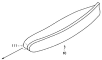
- FIG. 1 is an explanatory diagram for describing an example of a schematic configuration of the information processing apparatus according to the first embodiment of the present disclosure.
- the information processing apparatus 10 is configured as a so-called wearable device. More specifically, the information processing apparatus 10 has a ring shape that is partially opened (in other words, a headband shape or a U-shape), and at least one of the inner surfaces of the ring-shaped portion. The part is attached to the user so as to contact a part of the user's neck (that is, to hang around the neck).
- the information processing apparatus 10 includes a sound collection unit such as a so-called microphone, and collects sound emitted by the user from the sound collection unit as acoustic information.
- the information processing apparatus 10 includes a plurality of sound collection units denoted by reference numerals 111 to 113. More specifically, the sound collection units 111 to 113 are supported by the housing 101 of the information processing apparatus 10, for example.
- FIG. 2 is an explanatory diagram for explaining an example of a schematic configuration of the information processing apparatus 10 according to the present embodiment, and a configuration of a portion of the information processing apparatus 10 in which the sound collection unit 111 is provided. It is the figure which showed an example.
- the information processing apparatus 10 has a streamlined shape so as to protrude toward the front of the user in the vicinity of the user's mouth when worn on the user's neck.
- the sound collecting portion 111 is provided at the tip of the convex portion (or in the vicinity of the tip) so as to face the direction in which the convex portion protrudes.
- the sound collection unit 111 is configured as a device separate from the information processing apparatus 10, and faces the direction in which the convex portion protrudes with respect to the tip of the convex portion (or the vicinity of the tip). It may be supported.
- the sound collection unit 110 is provided for the information processing device 10
- the sound collection unit 110 is separated from the information processing device 10 and the information processing device 10 is provided. The case where it is supported by at least a part of the device 10 can also be included.
- the sound collection units 112 and 113 are provided to face the information processing apparatus 10 in different directions. More specifically, the sound collection units 112 and 113 are provided at positions that are substantially symmetric with respect to the user's neck when the information processing apparatus 10 is attached to the user's neck. Details of the position where each sound collecting unit is provided will be described later.
- the sound collecting portions 112 and 113 are provided so as to face the outside of the ring (that is, the side opposite to the center of the ring) with respect to the ring-shaped casing 101. ing. That is, the sound collection unit 112 and the sound collection unit 113 are provided so as to face opposite directions.
- the information processing apparatus 10 uses the voice recognition technology or the natural language processing technology for the user's voice (acoustic information) collected by the sound collection unit (for example, the sound collection units 111 to 113). By performing an analysis based on the above, the content spoken by the user may be recognized. Thereby, the information processing apparatus 10 can recognize, for example, the instruction content from the user and execute various processes (applications) according to the recognition result.
- the information processing apparatus 10 may have a so-called call function.
- the information processing apparatus 10 may transfer the sound collected by the sound collection unit (for example, the sound collection units 111 to 113) to another information processing apparatus that is a call partner.
- the information processing apparatus 10 configured to be carried by the user like a so-called wearable device as shown in FIG. 1 has various usage scenes such as when used outdoors, and the information A situation is assumed in which the environment around the processing apparatus 10 changes dynamically. Under such circumstances, for example, randomly generated noise such as wind noise, noise due to vibration, and rubbing due to wearing of the apparatus is collected by the sound collecting unit of the information processing apparatus 10. There is a case.
- the information processing apparatus 10 is configured as a wearable device that is worn on the user's neck.
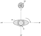
- the result of the examination regarding the installation position of the sound collecting unit that can be performed will be described. More specifically, it is assumed that a so-called wind noise is assumed to be noise, and each of the sound collection units when the wind is applied from different angles to the information processing apparatus 10 in which the sound collection units are installed at a plurality of locations. An example of the observation result of wind noise by will be described.
- FIG. 3 is an explanatory diagram for explaining an example of an observation environment for observing the effect of wind noise.
- the information processing apparatus 10 is mounted on the neck of a dummy doll U1 that imitates a part above the user's chest, and the circulator U2 is disposed in front of the dummy doll U1. Then, with the vertical direction of the dummy doll U1 as an axis, the dummy doll U1 is rotated in increments of 10 degrees within a range of 0 degrees to 360 degrees, so that the wind from the circulator U2 arrives at the information processing apparatus 10 The level of wind noise collected by each sound collecting unit was observed.
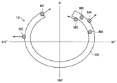
- FIG. 4 shows an example of the installation positions of the plurality of sound collection units provided in the information processing apparatus 10 in this observation.
- sound collection units M1 to M6 are installed for the information processing apparatus 10.
- the markers attached to the information processing apparatus 10 schematically indicate the positions where the sound collecting units M1 to M6 are installed.
- the said arrow has shown the direction of the sound collection part corresponding to the said marker.
- the sound collection unit corresponding to the marker that is, the sound collection units M3 and M6
- the sound collection unit M1 corresponds to the sound collection unit 111 in the information processing apparatus 10 described with reference to FIG. That is, the sound collection unit M1 is a convex portion provided so as to protrude toward the front of the user at a position corresponding to the vicinity of the user's mouth when the information processing apparatus 10 is worn by the user. It is provided at the tip.
- the sound collection unit M5 corresponds to the sound collection unit 112 in the information processing apparatus 10 described with reference to FIG. That is, when the information processing apparatus 10 is attached to the user, the sound collecting unit M5 is located at a position corresponding to the left side of the user (direction of approximately 270 degrees in FIG. 3). Outside the housing 101 (in other words, approximately 270 degrees in FIG. 3).
- the sound collection units M2 to M4 and M6 are positions corresponding to the area on the right front side of the user (in other words, the direction of approximately 45 degrees in FIG. 3) when the information processing apparatus 10 is worn by the user. Is provided.
- the sound collection unit M ⁇ b> 2 is interposed between the housing 101 of the information processing apparatus 10 and the user's neck and is installed so as to face the inside of the housing 101.
- the sound collection unit M4 is provided outside the housing 101 of the information processing apparatus 10 so as to face the outside of the housing 101 (in other words, the direction of approximately 45 degrees in FIG. 3).
- the sound collection units M3 and M6 are provided so as to face vertically upward as described above.
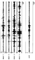
- FIG. 5 is an explanatory diagram for explaining an example of observation results of wind noise by each of the sound collection units when wind is applied to the information processing apparatus 10 from different angles. That is, FIG. 5 shows an example of a wind noise collection result by each of the sound collection units M1 to M6 described with reference to FIG. 4 in the observation environment described with reference to FIG.
- the numerical values described in the circumferential direction indicate the direction in which the wind from the circulator U2 arrives.
- the numerical values described along the radial direction of the graph indicate the level of the sound collected by the corresponding sound collection unit (that is, the observation level of the sound collection unit). That is, in the graph showing the sound collection results of the sound collection units M1 to M6 shown in FIG. 5, the smaller the observation level (in other words, the more the observation value is located inside the graph), the wind noise (ie, noise). ) Is less affected.
- the influence of the wind noise is small particularly in the situation where the wind comes from the front of the user (ie, the direction of 0 degree).
- the sound collecting unit M1 it can be seen that the effect of wind noise is small compared to other sound collecting units even when the wind comes from directions other than the front.
- the sound collection unit 111 shown in FIG. 1 the sound collection unit is provided at the tip of the streamlined projection (or in the vicinity of the tip) so that the projection protrudes.
- the influence of randomly generated noise such as wind noise can be reduced.
- the user's part for example, the neck or the head
- the information processing apparatus 10 can be used as a shield against wind or the like.
- the sound collection unit it is estimated that the characteristics of other sound collection units (for example, the sound collection unit 111 shown in FIG. 1) can be supplemented.
- the information processing apparatus 10 is configured as a wearable device that is worn on the user's neck as an example.
- the result of the study on the installation position of the sound collection unit that can collect sound ie, reduce the influence of noise such as wind noise has been described.
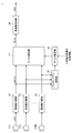
- FIG. 6 is a block diagram illustrating an example of a functional configuration of the information processing apparatus 10 according to the present embodiment.
- the information processing apparatus 10 includes a plurality of sound collecting units 111 to 11M (M is a positive integer), a frequency resolving unit 13, a channel power estimating unit 15, a filter estimating unit 16, a filter A processing unit 17 and a frequency synthesis unit 18 are included.
- the sound collection units 111 to 11M may be referred to as “sound collection unit 110” unless they are particularly distinguished.
- the number of sound collecting units 110 (that is, M) is not particularly limited as long as it is plural, but is more preferably 3 or more.
- the sound collection unit 110 is configured as a sound collection device for collecting sound of the external environment (that is, sound that propagates through the external environment) like a so-called microphone. Note that the voice input from the user is also taken into the information processing apparatus 10 by being collected by the sound collection unit 110.
- the sound collection unit 110 may include a plurality of sound collection devices such as a microphone array.
- the sound collection unit 110 outputs an acoustic signal based on the sound collection result of the sound of the external environment to the frequency decomposition unit 13. Note that the acoustic signal output from the sound collection unit 110 may be input to the frequency decomposition unit 13 after the gain is adjusted by an amplifier or the like, converted from an analog signal to a digital signal by AD conversion, and the like.
- the channel number of the sound collection unit 110 is m (1 ⁇ m ⁇ M) and the discrete time is n
- the acoustic signal output from the sound collection unit 110 is represented by x m (n). It shall be expressed as
- the frequency decomposing unit 13 is configured to decompose the acoustic signal x m (n) output from the sound collecting unit 110 into frequency components and output the frequency components. Specifically, the frequency resolving unit 13 performs frame division, application of a predetermined window function, and time-frequency conversion (for example, FFT (Fast Fourier Transform), etc.) on the acquired acoustic signal x m (n). The acoustic signal x m (n) is decomposed into frequency components by performing processing such as DFT (Discrete Fourier Transform). In the following description, the frequency component of the acoustic signal x m (n) may be described as X m (i, k).
- each frequency component X m (i, k) of the acquired acoustic signal x m (n) is output to each of the filter processing unit 17 and the channel power estimation unit 15 located in the subsequent stage. To do. Thereby, for each of the sound collecting units 111 to 11M, each frequency component X m (i, k) of the acoustic signal x m (n) is output to the filter processing unit 17 and the channel power estimation unit 15, respectively. It will be.
- the channel power estimation unit 15 acquires each frequency component X m (i, k) of the acoustic signal x m (n) for each sound collection unit 110 (that is, for each of the sound collection units 111 to 11M) from the frequency decomposition unit 13. To do. Next, the channel power estimation unit 15 determines the power of each sound collecting unit 110 for each frequency based on each frequency component X m (i, k) of the acoustic signal x m (n) corresponding to each sound collecting unit 110. Estimate the spectrum.
- the power spectrum corresponding to the i frame and the frequency k in the m-th sound collecting unit 110 is P m (i, k)
- the power spectrum P m (i, k) is expressed by a calculation formula shown as (Formula 1) below.
- X m * (i, k) represents a conjugate complex number of X m (i, k).
- r represents a smoothing coefficient in the frame direction for suppressing a rapid change in power spectrum (0 ⁇ r ⁇ 1).
- the channel power estimation unit 15 outputs the estimation result of the power spectrum P m (i, k) of each sound collection unit 110 to the filter estimation unit 16 for each frequency.
- the filter estimation unit 16 Based on the estimation result of the power spectrum P m (i, k) of each sound collection unit 110 for each frequency output from the channel power estimation unit 15, the filter estimation unit 16 performs filtering after that. A filter coefficient for executing the process is calculated.
- the filter estimation unit 16 performs the following (Equation 2) based on the estimation result of the power spectrum P m (i, k) of each sound collection unit 110 acquired from the channel power estimation unit 15 for each frequency.
- Equation 2 A matrix R (i, k) shown as follows is generated.
- the filter estimation unit 16 determines, for each of the sound collection units 110, the frequency of each sound collection unit 110 based on the distance between the sound collection unit 110 and the target sound source (for example, the user's mouth).
- An array manifold vector a (k) showing attenuation and delay characteristics up to 110 is calculated. Note that the distance between the sound source of the target sound and each sound collection unit 110 is determined when the information processing apparatus 10 is attached to the user by the information processing apparatus 10 (and thus each information processing apparatus 10 provided with the information processing apparatus 10). It is possible to specify in advance based on the relative positional relationship between the sound collection unit 110) and the sound source.
- the array manifold vector a (k) is expressed by the following calculation formulas (Equation 3) and (Equation 4).
- d m is the target sound source (e.g., mouth) and, m-th sound collecting portion 110 (i.e., the sound collecting portion 11m) represents the distance between the.
- g m indicates the amount of attenuation until the target sound reaches the sound collecting unit 11m.
- ⁇ k indicates an angular frequency corresponding to the discrete frequency number k.
- C indicates the speed of sound.
- a matrix with a superscript T is used to indicate transposition of the matrix. In the following description, a matrix with a superscript T may be referred to as a “transposed vector matrix”.
- a matrix with a superscript H indicates a complex conjugate transpose of the matrix.
- a matrix with a superscript H may be referred to as a “complex conjugate transposed vector matrix”.
- the filter coefficient w (i, k) for each frequency is expressed by the following calculation formula (Formula 6). Note that i indicates a frame number, and k indicates a discrete frequency number.
- the filter coefficient w (i, k) shown as (Equation 6) above indicates the gain of the component a (k) coming from the target sound source (for example, the mouth), as shown in (Equation 5) above. 1 and a coefficient that minimizes noise components (for example, wind noise). Then, the filter estimation unit 16 outputs the filter coefficient w (i, k) calculated for each frequency to the filter processing unit 17.
- the filter processing unit 17 acquires each frequency component X m (i, k) of the acoustic signal x m (n) for each sound collection unit 110 (ie, for each of the sound collection units 111 to 11M) from the frequency decomposition unit 13. . Further, the filter processing unit 17 acquires the filter coefficient w (i, k) calculated for each frequency from the filter estimation unit 16. The filter processing unit 17 uses each frequency component X m (i, k) of the acoustic signal x m (n) for each sound collecting unit 110 as an input signal and is based on the acquired filter coefficient w (i, k) for each frequency. By performing the filtering process, an output signal Y (i, k) is generated.
- the filter processing unit 17 uses each frequency component X m (i, k) of the acoustic signal x m (n) for each sound collecting unit 110 as an input signal, and obtains a filter coefficient w (i for each acquired frequency. , K), the input signal is weighted and added to generate an output signal Y (i, k) for each frequency.
- the output signal Y (i, k) is expressed by a calculation formula shown as (Formula 7) below. Note that i indicates a frame number, and k indicates a discrete frequency number.
- the filter processing unit 17 outputs the output signal Y (i, k) generated for each frequency to the frequency synthesis unit 18.
- the frequency synthesizer 18 acquires the output signal Y (i, k) generated for each frequency from the filter processor 17.
- the frequency synthesizer 18 generates the acoustic signal y (n) by synthesizing the acquired output signal Y (i, k) for each frequency. That is, the frequency synthesizing unit 18 performs the reverse process of the frequency decomposing unit 13 described above. Specifically, the frequency synthesizer 18 performs frequency-time conversion (for example, IFFT (Inverse FFT), IDFT (Inverse DFT), etc.), a predetermined window for the output signal Y (i, k) for each frequency. By performing processing such as function application and frame synthesis, an acoustic signal y (n) in which the output signal Y (i, k) for each frequency is synthesized is generated.
- IFFT Inverse FFT
- IDFT Inverse DFT
- FIG. 7 shows an example of processing in which the information processing apparatus 10 according to the present embodiment acquires the target sound based on the sound collection results of the plurality of sound collection units 110.
- FIG. 7 an example in which four microphones of the sound collection units 111 to 114 are used as the plurality of sound collection units 110 is illustrated. That is, in the example shown in FIG. 7, each of the sound collection units 111 to 114 is obtained by an example of the sound collection result by each of the sound collection units 111 to 114 (ie, the collected sound signal) and the signal processing by the information processing apparatus 10.
- An example of an acoustic signal (synthetic sound) obtained by synthesizing the sound collection results is shown.
- the filtering process for synthesizing the sound collection results (more specifically, each frequency component X m (i, k) of the acoustic signal x m (n)) by each of the plurality of sound collection units 110.
- the coefficient w (i, k) is a characteristic that keeps the gain of the component a (k) coming from the sound source (for example, the mouth) of the target sound at 1 and minimizes the noise component (for example, wind noise).
- weighting is performed so that the input of the sound collecting unit 110 having a smaller noise component level (in other words, the sound collecting unit 110 having a smaller noise component effect) is prioritized, and each sound collecting unit 110 is prioritized.
- the sound collection results are synthesized.
- the information processing apparatus 10 is configured to synthesize the target sound from the sound collection results of each of the plurality of sound collection units 110. This is different from the configuration in which the sound collection unit 110 that obtains the sound collection result is simply switched. More specifically, in the case of a configuration in which the sound collecting unit 110 that acquires the sound collection result is simply switched, the acoustic signal may be deteriorated before and after the switching, and particularly noise such as wind noise. In a situation where the direction of arrival of the sound changes dynamically, the deterioration of the acoustic signal tends to be more obvious.
- the information processing apparatus 10 synthesizes the target sound by the signal processing described above, so that the direction in which noise such as wind noise arrives dynamically changes.
- the target sound can be acquired in a more natural manner without causing deterioration of the acoustic signal.
- the signal processing for the sound collection result of each sound collection unit 110 described above is merely an example, and weighting is performed so that the input of the sound collection unit 110 having a smaller noise component level is prioritized, and each sound collection unit 110 is prioritized.
- the content is not particularly limited as long as the sound collection results of the sound unit 110 can be synthesized.
- the frequency synthesizer 18 outputs the generated acoustic signal y (n) as a target sound collection result.
- the acoustic signal y (n) output from the frequency synthesizer 18 is used for various processes (for example, voice recognition, voice call, etc.) executed by the information processing apparatus 10, for example.
- the configuration illustrated in FIG. 6 is merely an example, and the configuration of the information processing apparatus 10 is not necessarily limited to the example illustrated in FIG. 6 as long as the various processes described above can be realized.
- the frequency resolving unit 13 is provided for each of the sound collecting units 111 to 11m. It is good also as a structure to process.
- a part of the configuration may be externally attached to the information processing apparatus 10.
- at least some of the plurality of sound collecting units 110 may be configured to be detachable from the information processing apparatus 10.
- the information processing apparatus 10 has the target sound based on the sound collection results of the plurality of sound collection units. The description has been given focusing on the process of acquiring the.
- FIG. 8 is a flowchart illustrating an example of a flow of a series of processes of the information processing apparatus 10 according to the present embodiment.
- Step S101 The sound of the external environment is taken into the information processing apparatus 10 by being collected by the plurality of sound collection units 110.
- the sound collection unit 110 adjusts the gain of an acoustic signal (analog signal) based on the sound collection result, converts the analog signal from a digital signal by AD conversion, and then converts the converted acoustic signal (digital signal) x m (n ) Is output to the frequency resolving unit 13.
- the frequency resolving unit 13 performs processing such as frame division, application of a predetermined window function, time-frequency conversion, and the like on the acoustic signal x m (n) output from the sound collecting unit 110.
- the acoustic signal x m (n) is decomposed into frequency components.
- the frequency resolving unit 13 outputs each frequency component X m (i, k) of the acoustic signal x m (n) to each of the filter processing unit 17 and the channel power estimating unit 15 located in the subsequent stage.
- each frequency component X m (i, k) of the acoustic signal x m (n) is output to the filter processing unit 17 and the channel power estimation unit 15, respectively. It will be.
- Step S105 The channel power estimation unit 15 acquires each frequency component X m (i, k) of the acoustic signal x m (n) from the frequency resolution unit 13 for each sound collection unit 110. Next, the channel power estimation unit 15 determines the power of each sound collecting unit 110 for each frequency based on each frequency component X m (i, k) of the acoustic signal x m (n) corresponding to each sound collecting unit 110. Estimate the spectrum. Then, the channel power estimation unit 15 outputs the estimation result of the power spectrum P m (i, k) of each sound collection unit 110 to the filter estimation unit 16 for each frequency.
- Step S107 Based on the estimation result of the power spectrum P m (i, k) of each sound collection unit 110 for each frequency output from the channel power estimation unit 15, the filter estimation unit 16 performs filtering after that. A filter coefficient w (i, k) for executing the processing is calculated.
- the filter estimation unit 16 generates a matrix R (i, k) based on the power spectrum P m (i, k) of each sound collection unit 110. Further, the filter estimation unit 16 determines, for each frequency, the attenuation and delay characteristics to the sound collection unit 110 based on the distance between the sound collection unit 110 and the target sound source for each frequency. The indicated array manifold vector a (k) is calculated. Then, the filter estimation unit 16 calculates a filter coefficient w (i, k) based on the generated matrix R (i, k) and the calculated array manifold vector a (k), and the filter coefficient w (i , K) is output to the filter processing unit 17.
- Step S109 The filter processing unit 17 acquires each frequency component X m (i, k) of the acoustic signal x m (n) for each sound collection unit 110 from the frequency decomposition unit 13. Further, the filter processing unit 17 acquires the filter coefficient w (i, k) calculated for each frequency from the filter estimation unit 16. The filter processing unit 17 uses each frequency component X m (i, k) of the acoustic signal x m (n) for each sound collecting unit 110 as an input signal, based on the acquired filter coefficient w (i, k) for each frequency. By weighting and adding the input signals, an output signal Y (i, k) for each frequency is generated. Then, the filter processing unit 17 outputs the output signal Y (i, k) generated for each frequency to the frequency synthesis unit 18.
- Step S111 The frequency synthesizer 18 performs processing such as frequency-time conversion, application of a predetermined window function, and frame synthesis on the output signal Y (i, k) for each frequency output from the filter processor 17.
- the output signal Y (i, k) for each frequency is synthesized.
- an acoustic signal y (n) in which the sound collection results by the sound collection units 110 are combined is generated.
- the acoustic signal y (n) generated by the frequency synthesizer 18 is used as a sound collection result for various processes (for example, voice recognition, voice call, etc.) executed by the information processing apparatus 10. .
- the information processing apparatus 10 performs the target sound based on the sound collection results of the plurality of sound collection units.
- the description has been given focusing on the process of acquiring the.
- Example> Next, another example of the information processing apparatus 10 according to the present embodiment will be described as an example.
- Example 1 An example of a wearable device attached to the neck> First, referring to FIG. 9 to FIG. 11, as an example 1, an information processing apparatus configured as a wearable device that can be worn on the user's neck like the so-called neckband type wearable device shown in FIG. An example will be described.
- FIG. 9 is an explanatory diagram for describing an example of the information processing apparatus according to the first embodiment, and illustrates an example of the information processing apparatus configured as a wearable device that can be worn on the user's neck.
- the information processing apparatus shown in FIG. 9 is referred to as an “information processing apparatus 10a” in order to distinguish it from the information processing apparatus 10 according to the above-described embodiment and the information processing apparatuses according to other examples. There is a case.
- the information processing apparatus 10a includes sound collection units 111 to 114.
- the sound collection units 111 to 113 correspond to the sound collection units 111 to 113 in the information processing apparatus 10 described above with reference to FIG.
- the sound collecting unit 114 is provided at a position behind the user so that the information processing apparatus 10a is attached to the user's neck so as to face the rear side of the user. With such a configuration, for example, it is possible to further reduce the influence of noise coming from behind the user.
- the information processing apparatus 10a is provided with convex portions having a streamlined shape protruding in the direction in which each of the sound collecting portions 112 to 114 faces at a position where the sound collecting portions 112 to 114 are installed.
- Each of the sound collecting portions 112 to 114 is provided at the tip.
- the sound collecting portions 112 to 114 also reduce the influence of noise such as wind noise as in the sound collecting portion 111, and the direction in which the convex portion protrudes (that is, the sound collecting portion). It is possible to collect sound coming from the direction in which the sound part is directed in a more preferable manner.
- the position where the convex portion is provided (that is, the position where the sound collecting portion 110 is provided) is not particularly limited. Therefore, for example, by providing various circuits such as a driver, a battery, and the like, a convex portion is provided at a location where the casing 101 may swell, and the sound collection unit 110 is provided at the tip of the convex portion (or in the vicinity of the tip). It is good also as a structure which provides.
- FIG. 10 is an explanatory diagram for explaining another example of the information processing apparatus according to the first embodiment, and illustrates an example of the information processing apparatus configured as a wearable device that can be worn on the user's neck.
- the information processing apparatus shown in FIG. 10 is referred to as an “information processing apparatus 10b” in order to distinguish it from the information processing apparatus 10 according to the above-described embodiment and the information processing apparatuses according to other examples. There is a case.
- the information processing apparatus 10b has a ring shape and is configured to be openable at a portion indicated by reference numeral 19. In addition, it is comprised so that attachment or detachment is possible between the edge parts which mutually spaces apart because the part shown with the referential mark 19 opens. With such a configuration, the information processing apparatus 10b is attached to the user so that the inner surface of the ring-shaped portion is in contact with the user's neck (that is, wound around the neck).
- the information processing apparatus 10b has the sound collecting units 115 to 118 at positions different from each other along the circumference of the ring-shaped casing (ie, on the side opposite to the center of the ring). It is provided to face.
- the sound collection units 115 to 118 correspond to the sound collection unit 110 (for example, the sound collection units 111 to 113 shown in FIG. 1) in the information processing apparatus 10 according to the above-described embodiment. To do.
- each of the sound collection units 115 to 118 shields noise coming from the opposite side to the direction in which the sound collection unit is facing by the user's part (that is, the neck) to which the information processing apparatus 10b is attached. Therefore, the influence of the noise is mitigated.
- each of the sound collection units 115 to 118 is supported so as to be closer to the user's neck than the information processing apparatus 10 shown in FIG. The influence of noise such as noise (particularly noise coming from the user's neck) is further alleviated.
- each of the sound collection units 115 to 118 is provided so as to face different directions, for example, the characteristics of other sound collection units may be supplemented based on the sound collection results of some sound collection units. It becomes possible.
- a streamline-shaped convex portion is provided on at least a part of the housing, and a sound collecting unit 110 (for example, at the vicinity of the convex portion) , At least a part of the sound collecting units 115 to 118) may be provided.
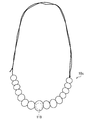
- FIG. 11 is an explanatory diagram for explaining another example of the information processing apparatus according to the first embodiment, and shows an example of the information processing apparatus configured as a wearable device having a shape like a so-called necklace. Yes.
- the information processing apparatus shown in FIG. 11 is referred to as an “information processing apparatus 10c” in order to distinguish it from the information processing apparatus 10 according to the above-described embodiment and the information processing apparatuses according to other examples. There is a case.
- reference numeral 119 indicates an example of the sound collection unit 110 in the information processing apparatus 10 according to the above-described embodiment. That is, in the information processing apparatus 10c having a shape like a necklace, for example, a streamline-shaped convex portion is provided in a portion corresponding to a so-called pendant so as to face the front of the user when the user wears the convex portion.
- the sound collecting unit 119 may be provided at the tip of the head (or in the vicinity of the tip).
- one sound collection unit 110 is provided for the information processing apparatus 10c, but a plurality of sound collection units 110 may be provided. Further, when a plurality of sound collecting units 110 are provided for the information processing apparatus 10c, the plurality of sound collecting units 110 may be provided so as to face different directions.
- an information processing apparatus configured as a wearable device that can be worn on the user's neck like the so-called neckband type wearable device shown in FIG. An example has been described.
- Example 2 Example of wearable device worn on head> Next, as a second embodiment, an example of an information processing apparatus configured as a wearable device that can be worn on the head will be described with reference to FIGS.
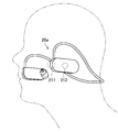
- FIG. 12 is an explanatory diagram for explaining an example of the information processing apparatus according to the second embodiment, and illustrates an example of the information processing apparatus configured as a wearable device that can be worn on the user's head.
- the information processing apparatus shown in FIG. 12 is referred to as an “information processing apparatus 20a” in order to distinguish it from the information processing apparatus 10 according to the above-described embodiment and the information processing apparatuses according to other examples. There is a case.
- the information processing apparatus 20a is mounted on the user's head so that a housing in which circuits and the like for realizing various functions are incorporated is held near the user's ear.
- the information processing device 20 a includes an earphone unit that is inserted into the user's ear canal and a cable-shaped support member that supports the housing by being hooked on the user's ear. Prepare.
- the housing is held near the user's ear by the earphone unit and the cable-shaped support member.
- the information processing apparatus 20a includes sound collection units 211 and 212.
- the sound collection units 211 and 212 are connected to the sound collection unit 110 (for example, the sound collection units 111 to 113 shown in FIG. 1) in the information processing apparatus 10 according to the above-described embodiment. Equivalent to.
- the information processing apparatus 20a when attached to the user's head, places the front side on an end portion of the casing that is held near the user's ear and located on the front side of the user.
- a convex portion having a streamline shape protruding so as to face is provided.
- the sound-collecting part 211 is provided in the front-end
- the information processing device 20a when the information processing device 20a is attached to the user's head, the information processing device 20a has at least a part of a side surface located outside the housing (that is, opposite to the head) in the direction of the outside ( That is, the sound collection unit 212 is provided so as to face the user's lateral direction.
- the information processing apparatus 20a includes a convex portion having a streamline shape that protrudes toward the outer side of the casing with respect to the side surface of the casing, and the sound collection unit 212 is provided at the tip of the convex portion. It may be provided.
- a configuration similar to the case to be held can be taken.
- the housing held on the right ear side may be provided with only a configuration corresponding to the sound collection unit 212, or a configuration corresponding to the sound collection units 211 and 212. Also good.
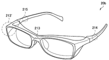
- FIG. 13 is an explanatory diagram for explaining another example of the information processing apparatus according to the second embodiment.
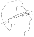
- the information processing apparatus is configured as a so-called glasses-type wearable device that is worn on the user's head. An example is shown.
- the information processing apparatus shown in FIG. 13 is referred to as an “information processing apparatus 20b” in order to distinguish it from the information processing apparatus 10 according to the above-described embodiment and the information processing apparatuses according to other examples. There is a case.
- the information processing apparatus 20b includes sound collection units 213 to 215.
- the sound collection units 213 to 215 are connected to the sound collection unit 110 (for example, the sound collection units 111 to 113 shown in FIG. 1) in the information processing apparatus 10 according to the embodiment described above. Equivalent to.
- a sound collection unit 213 is provided at least at a part corresponding to the front of the glasses.
- the information processing apparatus 20b includes a convex portion having a streamline shape that protrudes forward at a portion corresponding to a bridge of glasses, and a sound collecting portion is provided at the tip of the convex portion. 213 is provided so as to face the direction in which the convex portion protrudes.
- the convex portion and the sound collecting portion are provided in a portion corresponding to the front of the glasses other than the portion corresponding to the bridge. May be.
- the information processing apparatus 20b is provided with sound collection units 214 and 215 at least at a part corresponding to the temples of the glasses.
- the sound collection units 214 and 215 are provided so as to face in the direction opposite to the head (that is, the lateral direction of the user) when the information processing apparatus 20b is mounted on the user's head, for example. It is good to have been.
- FIG. 14 is an explanatory diagram for explaining another example of the information processing apparatus according to the second embodiment.
- the information processing apparatus shown in FIG. 14 is referred to as an “information processing apparatus 20c” in order to distinguish it from the information processing apparatus 10 according to the above-described embodiment and the information processing apparatuses according to other examples. There is a case.
- the information processing apparatus 20c includes sound collection units 216 to 218.
- the sound collection units 216 to 218 are connected to the sound collection unit 110 (for example, the sound collection units 111 to 113 shown in FIG. 1) in the information processing apparatus 10 according to the embodiment described above. Equivalent to.
- the sound collecting portions 216 to 218 are provided at different positions of the portions corresponding to the frame of the glasses (for example, the front and the temple) so as to face different directions. More specifically, each of the sound collection units 216 to 218 is provided so as to face the direction opposite to the head when the information processing apparatus 20c is attached to the user's head.
- each of the sound collecting units 216 to 218 is shielded by the user's head from the noise coming from the side opposite to the direction in which the sound collecting unit 216 is facing, so that the influence of the noise is not affected. Alleviated.
- the characteristics of other sound collection units may be supplemented based on the sound collection results of some sound collection units. It becomes possible.
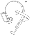
- FIG. 15 is an explanatory diagram for explaining another example of the information processing apparatus according to the second embodiment, and illustrates an example of the information processing apparatus configured as an overhead wearable device such as a so-called headphone. ing.
- the information processing apparatus shown in FIG. 15 is referred to as an “information processing apparatus 20d” in order to distinguish it from the information processing apparatus 10 according to the above-described embodiment and the information processing apparatuses according to other examples. There is a case.
- the information processing apparatus 20 d includes an imaging unit 25 and a sound collection unit 219.
- the sound collection unit 219 corresponds to the sound collection unit 110 (for example, the sound collection units 111 to 113 shown in FIG. 1) in the information processing apparatus 10 according to the above-described embodiment. .
- the imaging unit 25 can store the front of the user of the housing of the information processing device 20d within the angle of view. In the position.
- the imaging unit 25 is provided in the housing of the information processing device 20 d so as to face the front of the user.
- the information processing apparatus 20d includes a convex portion having a streamline shape that protrudes toward the front side of the user in a state of being mounted on the user's head in at least a part of the housing, and the convex portion
- a sound collecting portion 219 is provided at the front end of the head so as to face the direction in which the convex portion protrudes.
- the sound collection unit 219 is provided in the vicinity of the imaging unit 25.
- a streamline projecting so as to face the front side of the user on at least a part of the holding member for holding the information processing apparatus 20d on the head of the user.
- a sound collecting part may be provided at the tip of the convex part so as to face the direction in which the convex part protrudes.
- an example of an information processing apparatus configured as a wearable device that can be worn on the head has been described with reference to FIGS. 12 to 15.
- the example demonstrated above is an example to the last, and is not necessarily limited to the example shown above.
- a configuration corresponding to the sound collection unit 110 in the information processing apparatus 10 according to the above-described embodiment with respect to the information processing apparatus configured as a head-mounted wearable device having a so-called headband shape. May be provided.
- Example 3 Application example to portable information terminal> Next, as Example 3, an example of an information processing apparatus configured as a portable information terminal such as a so-called smartphone will be described with reference to FIGS. 16 and 17.
- FIG. 16 is an explanatory diagram for explaining an example of the information processing apparatus according to the third embodiment.
- the information processing apparatus shown in FIG. 16 is referred to as an “information processing apparatus 30” in order to distinguish it from the information processing apparatus 10 according to the above-described embodiment and the information processing apparatuses according to other examples. There is a case.
- the information processing apparatus 30 includes sound collection units 311 to 314.
- the sound collection units 311 to 314 are connected to the sound collection unit 110 (for example, the sound collection units 111 to 113 shown in FIG. 1) in the information processing apparatus 10 according to the above-described embodiment. Equivalent to.
- the housing of the information processing apparatus 30 has a substantially rectangular surface 36 at least in part, and a predetermined region including the corner of the surface 36 (that is, the corner or the vicinity of the corner). ), A convex portion having a streamline shape is formed so as to face the outside of the housing.
- the housing of the information processing apparatus 30 includes a substantially planar surface 36 and a plurality of side surfaces 371 to 374 formed so as to face different directions along the end of the surface 36, and are adjacent to each other.
- a convex portion having a streamline shape is formed in a predetermined region including a portion where the matching side surfaces are connected.
- the surface 36 may correspond to a surface on which a display unit such as a display is provided, for example.
- each of the sound collection units 311 to 314 is provided at the tip of any one of the convex portions (or in the vicinity of the tip) so as to face the outside of the casing of the information processing apparatus 30.
- FIG. 17 is an explanatory diagram for explaining an example of a usage form of the information processing apparatus 30 according to the modification 3. An example of a case where the user performs a voice call using the information processing apparatus 30 is illustrated. Show.
- the information is set so that the sound collecting unit 312 faces the front of the user.
- the processing device 30 is held.
- the sound collecting unit 312 is affected by wind noise caused by the wind coming from the front due to the movement of the user. It becomes difficult. It can be assumed that the user makes a voice call while holding the information processing apparatus 30 in the vicinity of his / her left ear.
- the information processing apparatus 30 is held so that the sound collecting unit 311 faces substantially in front of the user, and the sound collecting unit 311 winds off due to wind coming from the front due to the movement of the user. Less affected by sound. That is, the information processing apparatus 30 can mitigate the influence of wind noise caused by the wind coming from the front due to the movement of the user based on the configuration described above.
- the information processing apparatus 30 is provided so that the sound collecting units 311 to 314 face different directions. With such a configuration, the information processing apparatus 30 can supplement the characteristics of the other sound collection units based on the sound collection results of at least some of the sound collection units.
- FIGS. 16 and 17 As described above, as an example 3, an example of an information processing apparatus configured as a portable information terminal such as a so-called smartphone has been described with reference to FIGS. 16 and 17.
- Example 4 Application example to watch-type wearable device> Next, as Example 4, an example of an information processing apparatus configured as a so-called watch-type wearable device that can be worn on an arm will be described with reference to FIGS. 18 and 19.
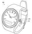
- FIG. 18 is an explanatory diagram for explaining an example of the information processing apparatus according to the fourth embodiment.
- the information processing apparatus shown in FIG. 18 is referred to as an “information processing apparatus 40a” in order to distinguish it from the information processing apparatus 10 according to the above-described embodiment and the information processing apparatuses according to other examples. There is a case.
- the information processing apparatus 40a includes sound collection units 411 to 415.
- the sound collection units 411 to 415 are connected to the sound collection unit 110 (for example, the sound collection units 111 to 113 shown in FIG. 1) in the information processing apparatus 10 according to the above-described embodiment. Equivalent to.
- the information processing apparatus 40a includes a casing 481 in which circuits for realizing various functions are incorporated, and a belt-like support member 482 that supports the casing 481 on the user's arm.
- the casing 481 has at least a part of a substantially rectangular surface, and the casing 481 has a predetermined area including corners of the substantially rectangular surface.
- a convex portion having a streamline shape is formed so as to face the outside of the body 481.
- the substantially rectangular surface corresponds to a surface on the side where a dial in a so-called timepiece is provided.
- Each of the sound collecting portions 411 to 414 is provided at the tip of one of the convex portions (or in the vicinity of the tip) so as to face the outside of the housing 481.
- the support member 482 includes a sound collection unit 415 at a position that is substantially symmetric with respect to the housing 481 with respect to the arm, and is opposite to the arm. It is provided so as to face the direction.
- the information processing apparatus 40a allows at least any one of the sound collection units 411 to 414 even under a situation where the user is waving the arm on the side on which the information processing apparatus 40a is mounted. However, it is in a state of facing the direction substantially equal to the direction in which the arm is swung. Therefore, the information processing apparatus 40a can mitigate the effect of wind noise caused by arm swing based on the sound collection results of the sound collection units 411 to 414. In addition, the information processing apparatus 40a is provided so that the sound collecting units 411 to 415 face different directions.
- the information processing apparatus 40a can supplement the characteristics of other sound collection units based on the sound collection results of at least some of the sound collection units 411 to 415.
- FIG. 19 is an explanatory diagram for explaining another example of the information processing apparatus according to the fourth embodiment.
- the information processing apparatus shown in FIG. 19 is referred to as an “information processing apparatus 40b” in order to distinguish it from the information processing apparatus 10 according to the above-described embodiment and the information processing apparatuses according to other examples. There is a case.
- the information processing apparatus 40b includes a sound collecting unit 416 in a portion corresponding to a so-called screw portion of a timepiece indicated by reference numeral 483 (hereinafter referred to as “screw portion 483”).
- the screw part 483 may be used as a convex part for providing the sound collection part 416 by forming the screw part 483 to have a streamlined shape.
- the sound collection unit 416 corresponds to the sound collection unit 110 (for example, the sound collection unit 111) in the information processing apparatus 10 according to the above-described embodiment.
- Example 5 Application Example to Imaging Device> Next, as Example 5, an example of an information processing apparatus configured as an imaging apparatus capable of capturing a moving image or a still image will be described with reference to FIGS. 20 and 21.
- FIG. 5 An example of an information processing apparatus configured as an imaging apparatus capable of capturing a moving image or a still image will be described with reference to FIGS. 20 and 21.
- FIG. 20 is an explanatory diagram for explaining an example of the information processing apparatus according to the fifth embodiment.
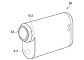
- the information processing apparatus shown in FIG. 20 is referred to as an “information processing apparatus 50” in order to distinguish it from the information processing apparatus 10 according to the above-described embodiment and the information processing apparatuses according to other examples. There is a case.
- reference numeral 53 corresponds to an image capturing unit for capturing images such as moving images and still images.
- Reference numerals 511 and 512 correspond to an example of a sound collection unit provided in the information processing apparatus 50.
- the sound collection units 511 and 512 are connected to the sound collection unit 110 (for example, the sound collection units 111 to 113 shown in FIG. 1) in the information processing apparatus 10 according to the embodiment described above. Equivalent to.
- the information processing device 50 includes, for example, a direction of the casing that supports the imaging unit 53 in which the imaging unit 53 captures an image (hereinafter referred to as “imaging direction”).
- imaging direction a direction of the casing that supports the imaging unit 53 in which the imaging unit 53 captures an image
- a convex portion having a streamline shape protruding in the imaging direction is provided on a part of the surface facing (which may be).
- a sound collection unit 511 is provided at the tip of the convex portion (or in the vicinity of the tip) so as to face the imaging direction of the imaging unit 53 (in other words, forward).
- FIG. 21 is an explanatory diagram for explaining an example of a schematic configuration in the vicinity of the lens of the imaging unit 53 in the information processing apparatus 50 according to the fifth embodiment.
- the information processing device 50 is provided with a convex portion 551 that protrudes toward the outside of the housing of the information processing device 50 in the vicinity of the lens of the imaging unit 53.
- the convex portion 551 includes a convex portion 553 having a streamline shape that protrudes in the imaging direction (that is, the front side) of the imaging unit 53, and is collected at the tip of the convex portion 553 (or in the vicinity of the tip).
- a sound unit 513 is provided.
- the information processing apparatus 50 can mitigate the effect of wind noise caused by the wind coming from the front due to the movement of the user, for example, even in a situation where an image is captured while the user is moving. Is possible.
- the information processing apparatus 50 may include another sound collection unit different from the sound collection units 511 and 512.
- the other sound collecting unit may be provided so as to face a different direction from the sound collecting units 511 and 512.
- the housing of the information processing device 50 is directed to the surface opposite to the imaging direction of the imaging unit 53 and to the direction opposite to the imaging direction (that is, rearward).
- the other sound collecting unit may be provided. With such a configuration, for example, the characteristics of the sound collection units 511 and 512 can be supplemented based on the sound collection result by another sound collection unit.
- Example 5 an example of an information processing apparatus configured as an imaging apparatus capable of capturing a moving image or a still image has been described with reference to FIGS. 20 and 21.
- Second Embodiment >> ⁇ 2.1. Overview> Subsequently, a second embodiment of the present disclosure will be described.
- the input of the sound collection unit having a smaller observation level that is, the level of the collected sound
- the filtering process so as to be prioritized, the influence of noise generated randomly such as wind noise has been reduced.
- Such control makes it possible to mitigate the influence of the noise in a more preferable manner, particularly when the influence of randomly generated noise such as wind noise is larger.
- the target sound is more accurately obtained in a situation where the target sound such as speech is collected as a main component.
- the sound collection result of the sound collection unit collected at a high level may not be used. That is, in the situation where the influence of randomly generated noise such as wind noise is small, for example, the sound collection result of the sound collection unit having a small signal-to-noise ratio is preferentially used. There is.
- the present embodiment maintains the effect of suppressing noise generated randomly such as wind noise as in the first embodiment described above, and is more preferable when the influence of randomly generated noise is small.
- An example of a mechanism that can acquire the target sound in various ways is proposed.
- FIG. 22 is a block diagram illustrating an example of a functional configuration of the information processing apparatus according to the present embodiment.
- information processing apparatus 60 May be called.
- the information processing apparatus 60 includes a plurality of sound collecting units 111 to 11M (M is a positive integer), a frequency resolving unit 13, a channel power estimating unit 65, and filter estimation.
- a unit 66, a filter processing unit 17, and a frequency synthesis unit 18 are included.
- the plurality of sound collecting units 111 to 11M (M is a positive integer), the frequency resolving unit 13, the filter processing unit 17, and the frequency synthesizing unit 18 are the information processing apparatus according to the first embodiment described above. 10 (refer to FIG. 6) corresponds to the configuration with the same reference numerals.
- the information processing apparatus 60 according to the present embodiment is different from the information processing apparatus 10 according to the first embodiment described above in the processing contents of the channel power estimation unit 65 and the filter estimation unit 66. Therefore, hereinafter, the functional configuration of the information processing apparatus 60 according to the present embodiment will be described, particularly focusing on differences from the information processing apparatus 10 according to the first embodiment described above. Detailed description of the same configuration as in FIG.
- the channel power estimation unit 65 includes an input power estimation unit 651, a non-correlated component power estimation unit 653, and a random noise power estimation unit 655.
- the input power estimation unit 651 corresponds to the channel power estimation unit 15 in the information processing apparatus 10 according to the first embodiment described above. That is, the input power estimation unit 651 is configured to output the power of each sound collecting unit 110 for each frequency based on each frequency component X m (i, k) of the acoustic signal x m (n) corresponding to each sound collecting unit 110. Estimate the spectrum. Then, the input power estimation unit 651 outputs the estimation result of the power spectrum P m (i, k) of each sound collection unit 110 to the random noise power estimation unit 655 for each frequency.
- the uncorrelated component power estimation unit 653 receives feedback of the output signal Y (i, k) generated by the filtering processing unit 17 performing the filtering process.
- the output signal Y (i, k) is noise (random noise) in each frequency component X m (i, k) of the acoustic signal x m (n) for each sound collecting unit 110 that has been previously collected.
- the sound of which the influence is suppressed corresponds to a frequency component of each sound collection unit 110 of a target sound such as a voice spoken by the user.
- the decorrelation component power estimation unit 653 outputs each frequency component X m (i, k) of the acoustic signal x m (n) corresponding to each sound collection unit 110 and the feedback output signal Y (i, k).
- the frequency component X m (i, k) the component that is uncorrelated with the output signal Y (i, k) (hereinafter, also simply referred to as “non-correlated component”) is the frequency component X m (i, k). This corresponds to a noise component such as random noise included in k).
- the uncorrelated component power estimation unit 653 outputs the estimation result of the power spectrum Q m (i, k) of each sound collection unit 110 to the random noise power estimation unit 655 for each frequency.
- the random noise power estimation unit 655 acquires an estimation result of the power spectrum P m (i, k) of each sound collection unit 110 for each frequency from the input power estimation unit 651. In addition, the random noise power estimation unit 655 acquires an estimation result of the power spectrum Q m (i, k) of the uncorrelated component corresponding to each sound collecting unit 110 for each frequency from the uncorrelated component power estimation unit 653. . Then, the random noise power estimation unit 655 uses the filter estimation unit 66 to calculate the filter coefficient w (i, k) based on the obtained estimation results of the power spectra P m (i, k) and Q m (i, k). The power spectrum Wm (i, k) of each sound collection unit 110 for each frequency for calculation is determined.
- the random noise power estimation unit 655 outputs information indicating the power spectrum Wm (i, k) of each sound collection unit 110 to the filter estimation unit 66 for each frequency.
- the filter estimation unit 66 Based on information indicating the power spectrum Wm (i, k) of each sound collection unit 110 for each frequency output from the channel power estimation unit 65, the filter estimation unit 66 performs a filtering process. A filter coefficient w (i, k) for calculating the value is calculated. At this time, when generating the above-described matrix R (i, k) shown as (Equation 2), the filter estimation unit 66 replaces the power spectrum P m (i, k) with the power spectrum Wm (i , K) is different from the filter estimation unit 16 according to the first embodiment described above.
- the filter coefficient w based on the array manifold vector a (k) and the generated matrix R (i, k) generated as described above based on the subsequent processing that is, (Expression 3) to (Expression 6).
- the processing related to the calculation of (i, k) is the same as that of the filter estimation unit 16 according to the first embodiment described above. Therefore, detailed description of the contents of the processing is omitted.
- the filter estimation unit 66 calculates the filter coefficient w (i, k) based on the information indicating the power spectrum Wm (i, k) of each sound collection unit 110 for each acquired frequency.
- the filtered filter coefficient w (i, k) is output to the filter processing unit 17.
- the subsequent processing is the same as that of the information processing apparatus 10 (see FIG. 6) according to the first embodiment described above.
- the sound (signal) input to the sound collection unit such as a microphone includes, for example, a target sound S m such as a user's voice, a so-called background noise N m, and a random noise W m such as a wind noise. And are included. That is, each frequency component X m (i, k) of the acoustic signal x m (n) for each sound collecting unit 110 is based on the target sound S m , the background noise N m , and the random noise W m as follows: It is represented by the relational expression shown as 8).
- S is for the target sound S m summarizes the M sound collecting unit.
- N represents the background noise
- N m is a summary for M sound collecting unit
- W is one in which the random noise W m summarizes the M sound collecting unit.
- S, N, and W are each shown as a vector.
- S org indicates the target sound itself output from the sound source, and is represented by a scalar value.
- a k corresponds to the array manifold vector a (k) described above.
- S indicates a component of the target sound that takes into account the effects of signal degradation, delay, and the like that occur when the target sound S org output from the sound source propagates through the space until it reaches the sound collection unit. Yes.
- the generation timing of random noise W such as wind noise is random, and in the information processing apparatus according to the present disclosure, a plurality of sound collection units (particularly, sound collections arranged in a distributed manner as shown in FIG. 1). Part) can be defined as signals having no correlation.
- Equation 9 can be defined as a relationship between vectors as shown in FIG.
- FIG. 23 is an explanatory diagram for explaining a basic principle of processing of the uncorrelated component power estimation unit 653.
- the vector space shown in FIG. 23 is defined based on the manifold vector ak .
- X represents the sound collected by the sound collection unit (that is, the input signal), and corresponds to X shown in (Equation 9).
- Y ideally corresponds to a component based on the estimation result of the target sound S org with respect to the input signal X (that is, a user's utterance component). That is, the component Y schematically shows a user's speech component (or a component having a correlation with the user's speech component) among the components included in the input signal X.
- Z corresponds to a component having a small correlation (or no correlation) with the user's speech component among the components included in the input signal X.
- the component Z is only the background noise N and the random noise W.
- the background noise N is , It is observed as a component having a correlation between the sound collecting parts. Therefore, the component Y includes a background noise N component in addition to the user's utterance component S.
- random noise W such as wind noise is indicated as a component Z because the correlation with the user's speech component is small.
- the uncorrelated component power estimation unit 653 uses the feedback of the output signal Y (that is, the user's utterance component), thereby having a small correlation (or correlation) with the output signal Y.
- a component having no property is extracted as a component of random noise W.
- the component Z is also referred to as “non-correlated component Z”.
- the array manifold vector a k is expressed by the calculation formula shown below as (Formula 10) based on the calculation formula described above as (Formula 4).
- an input signal X based on the inner product of the manifold vector a k, it is possible to extract a component obtained by projecting the input signal X to the manifold vectors a k. From such characteristics, it is possible to extract the non-correlated component Z as a component orthogonal to the manifold vector ak based on the calculation formula shown below as (Equation 11).
- the power spectrum Q m (i, k) of the decorrelation component Z corresponding to the i frame and the frequency k in the m-th sound collecting unit 110 (that is, the sound collecting unit 11m) is expressed as (Equation 14) below. It is expressed by the calculation formula shown as In (Expression 14) shown below, Z m * (i, k) represents a conjugate complex number of Z m (i, k). In (Expression 14), r represents a smoothing coefficient in the frame direction for suppressing a rapid change in power spectrum (0 ⁇ r ⁇ 1).
- the uncorrelated component power estimation unit 653 calculates the power spectrum Q m (i, k) of the uncorrelated component.
- the non-correlated component power estimation unit 653 may not necessarily collect all the sound collection units 110 if the sound collection results of two or more sound collection units 110 can be used when estimating the power spectrum Q m (i, k). There is no need to use sound results.
- the uncorrelated component power estimation unit 653 is installed at a position where it is difficult to collect a target sound such as a voice, such as the sound collection unit 110 located behind the user's head. The sound collection result of the sound unit 110 may not be used for estimating the power spectrum Q m (i, k).
- the random noise power estimation unit 655 includes the power spectrum P m (i, k) acquired from the input power estimation unit 651 and the power spectrum of the non-correlation component acquired from the non-correlation component power estimation unit 653.
- a power spectrum Wm (i, k) is determined based on each estimation result of Q m (i, k).
- the random noise power estimation unit 655 may output the estimation result of the power spectrum Q m (i, k) of the uncorrelated component to the filter estimation unit 66 as the power spectrum Wm (i, k).
- the channel power estimation unit 65 may not include the input power estimation unit 651.
- the random noise power estimation unit 655 selectively selects one of the estimation results of the power spectra P m (i, k) and Q m (i, k) based on a predetermined condition.
- the power spectrum Wm (i, k) may be output to the filter estimation unit 66.
- the random noise power estimation unit 655 adaptively applies the power spectrum Wm (i, k) based on the estimation results of the power spectra P m (i, k) and Q m (i, k). May be calculated.
- the random noise power estimation unit 655 receives the power spectrums P m (i, k) and Q m (i, k) as inputs, and based on the calculation formula shown below as (Equation 15), the target sound (sound, etc.)
- the power spectrum W m ⁇ taking into account the relationship between the noise and the random noise is calculated. Note that “W m ⁇ ” indicates characters with a tilde on “W m ”. Further, Pm and Qm shown below are generalized descriptions of the power spectra P m (i, k) and Q m (i, k).
- Equation 16 calculates the power spectrum W m ⁇ taking into account the relationship between the target sound and random noise, using the power spectra P m (i, k) and Q m (i, k) as inputs.
- Equation 16 calculates the power spectrum W m ⁇ taking into account the relationship between the target sound and random noise, using the power spectra P m (i, k) and Q m (i, k) as inputs.
- a specific example of the function F for doing this is shown.
- the random noise power estimation unit 655 calculates the power spectrum Wm based on the calculation formula shown below as (Equation 17) based on the power spectrum W m ⁇ in consideration of the relationship between the target sound and the random noise.
- Equation 17 r represents a smoothing coefficient in the frame direction for suppressing a sudden change in power spectrum (0 ⁇ r ⁇ 1). That is, the random noise power estimation unit 655 may smooth the power spectrum Wm calculated based on the calculation formula shown below as (Equation 17) between frames based on the setting of the coefficient r.
- the power spectrum P m shown in (Equation 16), that is, the estimation result of the power spectrum P m (i, k) by the input power estimation unit 651 is collected by the sound collection unit 110 as described above.
- the power spectrum Q m shown in (Equation 16) that is, the estimation result of the power spectrum Q m (i, k) by the uncorrelated component power estimation unit 653 is the random noise such as wind noise.
- the weight Q m / (P m + Q m ) shown in (Equation 16) changes based on the relationship between the target sound such as speech and random noise such as wind noise.
- the weight Q m / (P m + Q m ) indicates control that further suppresses use of the sound collection result of the corresponding channel (that is, the sound collection unit 110).
- the reciprocal of the weight Q m / (P m + Q m ) is applied to the calculation of the filter coefficient w (i, k). Therefore, when the signal level of the target sound is sufficiently high with respect to random noise, the filter coefficient w (i, k) is calculated so that the use of the sound collection result by the corresponding channel is given higher priority. It becomes.
- weight Q m / (P m + Q m) indicates control that gives priority to the use of the sound collection result of the corresponding channel (that is, the sound collection unit 110).
- the reciprocal of the weight Q m / (P m + Q m ) is applied to the calculation of the filter coefficient w (i, k). Therefore, when the influence of random noise is greater, the filter coefficient w (i, k) is calculated so that the use of the sound collection result by the corresponding channel is suppressed.
- the sound collecting unit 110 that has collected the sound at a higher sound level. The result is used more preferentially to calculate the filter coefficient w (i, k).
- the sound collection result of the sound collection unit 110 having a smaller observation level is more preferentially the same as in the first embodiment described above.
- the random noise power estimation unit 655 uses the power spectrum Wm (i, k) for calculating the filter coefficient w (i, k) as the target sound such as speech and the wind noise. It is possible to calculate adaptively according to the relationship with random noise.
- the random noise power estimation unit 655 may output the power spectrum Wm (i, k) calculated based on (Equation 17) to the filter estimation unit 66.
- the random noise power estimation unit 655 determines the power spectrum Wm (i, k) of each sound collection unit 110 for each frequency used for calculating the filter coefficient w (i, k) have been described above. did.
- the example described above is merely an example, and the power spectrum Wm (i, k) is calculated based on the estimation result of at least one of the power spectra P m (i, k) and Q m (i, k).
- the content is not particularly limited as long as it can be determined.
- the information processing apparatus 60 includes the sound collection results obtained by at least two or more sound collection units 110 among the plurality of sound collection units 110 and the output signal Y (i, The power spectrum Q m (i, k) of the non-correlated component is estimated based on the feedback of k).
- the information processing apparatus 60 uses the estimation result of the power spectrum Q m (i, k) of the non-correlated component for estimation of the filter coefficient w (i, k).
- the information processing apparatus 60 maintains the effect of suppressing noise generated randomly such as wind noise as in the first embodiment described above, and further, the influence of noise generated randomly is small. In some cases, the target sound can be acquired in a more preferable manner.
- the signal processing according to the present embodiment has been described focusing on the case where it is applied to the so-called neckband type wearable device shown in FIG.
- the application destination of the signal processing according to the present embodiment is not necessarily limited to the example shown in FIG.
- the signal processing according to the present embodiment can be applied to any device that includes a plurality of sound collection units. More preferably, the plurality of sound collection units may be arranged so that the distances from the sound source of the target sound (for example, the mouth where the voice is spoken) are different from each other. More preferably, the plurality of sound collecting units may be arranged so as to be positioned in different directions with respect to the sound source of the target sound.
- the multi-channel Wiener filter is a technique used for background noise suppression or the like.
- W mwf is calculated based on the calculation formula shown as (Equation 18) below.
- Equation 18 S indicates the target sound, such as sound or the like, corresponding to S org shown in the foregoing (Equation 9).
- X represents the sound collected by the sound collection unit (that is, the input signal), and corresponds to X shown in (Equation 9) described above.
- W schematically shows a filter applied to the input signal X in the multi-channel Wiener filter.
- the multi-channel Wiener filter ideally restores the original signal based on the filter that minimizes the cost function shown in (Equation 18) above.
- X i represents an output signal based on the sound collection result by the channel used as a reference.
- the reference channel is also referred to as a “reference microphone”.
- N represents background noise, and corresponds to N shown in the above (Equation 9).
- the coefficient ⁇ is a coefficient (weight) set according to the amount of noise suppression for the target sound, and is set in advance based on, for example, a result of a prior experiment or the like.
- R x and R n in the above (Formula 19) are represented by the following calculation formulas as (Formula 20) and (Formula 21).
- the reference microphone is specified by e i.
- e i is an M-order vector in which only the i-th value is 1 and the other values are 0, and is expressed as (Equation 22) shown below, for example.
- X represents an input signal based on the sound collection results from each of a plurality of channels as a vector. That is, R x is calculated from the input signal X itself. Further, in (Expression 21), N is an input signal based on the sound collection results of each of a plurality of channels in a section where the target sound is not collected (hereinafter also referred to as “pause section”) (ie, equivalent to noise). Signal) is represented by a vector. Therefore, R n is calculated, for example, in a pause period that is specified based on a detection result of a section in which the target sound is collected (hereinafter also referred to as “target sound section”).
- R x is also referred to as “input correlation matrix”
- R n is also referred to as “noise correlation matrix”.
- Random noise such as clothing rubbing may be collected by the sound collection unit.
- the random noise is mixed into e i by sound collecting unit which is determined fixedly in (Equation 19) (i.e., reference microphone) is the random noise Is difficult to suppress.
- this embodiment proposes an example of a mechanism for further reducing the influence of random noise in the multichannel Wiener filter by applying the technique described above in the other embodiments to the multichannel Wiener filter.
- a sound collection unit that is less influenced by random noise is adaptively selected as a reference microphone based on the estimation result of the power spectrum Pm (or power spectrum Wm) described above. By doing so, the influence of random noise is further reduced.
- the calculation formula shown below as (Formula 23) shows the basic principle relating to the derivation of the multi-channel Wiener filter W mwf in the information processing apparatus according to the present embodiment.
- the output signal X i based on the sound collection result by the reference microphone is described in the other embodiments.
- the output signal Y based on the estimation result of the power spectrum Pm (or power spectrum Wm) is applied.
- the information processing apparatus according to the present embodiment can generate random noise even in a situation where the influence of random noise appears more significantly (that is, in a situation where the surrounding environment changes dynamically).
- the sound collecting part having a smaller influence is dynamically selected as a reference microphone.
- the influence of random noise is further reduced as compared with a conventional apparatus to which a multi-channel Wiener filter is applied, and thus the target sound is extracted in a more preferable manner. It becomes possible to do.
- the information processing apparatus according to the present embodiment will be described in more detail.
- FIG. 24 is a block diagram illustrating an example of a functional configuration of the information processing apparatus according to the present embodiment.
- device 70 In the following description, in order to explicitly distinguish the information processing apparatus according to the present embodiment from the information processing apparatuses according to the other embodiments described above (for example, the information processing apparatuses 10 and 60), Sometimes referred to as device 70 ".
- the information processing apparatus 70 includes a plurality of sound collecting units 111 to 11M (M is a positive integer), a frequency resolving unit 13, a channel power estimating unit 71, and filter estimation.
- Unit 72 input correlation matrix calculation unit 73, noise correlation matrix calculation unit 74, multichannel winner filter calculation unit 75, multichannel winner filter processing unit 76, and frequency synthesis unit 77.
- the plurality of sound collecting units 111 to 11M (M is a positive integer) and the frequency resolving unit 13 have the same signs in the information processing apparatus 10 (see FIG. 6) according to the first embodiment described above. It corresponds to the attached structure.
- the information processing apparatus 70 includes a channel power estimation unit 71, a filter estimation unit 72, an input correlation matrix calculation unit 73, a noise correlation matrix calculation unit 74, and a multichannel winner filter calculation unit 75.
- the processing contents of the multi-channel winner filter processing unit 76 and the frequency synthesis unit 77 are different from those of the information processing apparatus 10 according to the first embodiment described above. Therefore, hereinafter, the functional configuration of the information processing apparatus 70 according to the present embodiment will be described, particularly focusing on differences from the information processing apparatus 10 according to the first embodiment described above. Detailed description of the same configuration as in FIG.
- Multi-channel winner filter processing unit 76 The multi-channel Wiener filter processing unit 76 acquires each frequency component X m (i, k) of the acoustic signal x m (n) for each sound collection unit 110 from the frequency decomposition unit 13. In addition, the multi-channel winner filter processing unit 76 acquires the calculation result of the multi-channel winner filter W mwf (i, k) for each frequency from the multi-channel winner filter calculation unit 75 described later. The details of the method for calculating the multi-channel winner filter W mwf (i, k) will be described later.
- the multi-channel Wiener filter processing unit 76 the frequency components X m (i, k) of the acoustic signal x m for each sound collector 110 (n) as an input signal, the multi-channel Wiener filter W mwf (i, By performing the filtering process based on k), the output signal S is generated for each frequency.
- the output signal S is expressed by a calculation formula shown as (Equation 24) below. In the following (Equation 24), the description of the frame number i and the discrete frequency number k is omitted.
- the multi-channel winner filter processing unit 76 outputs the output signal S generated for each frequency to the frequency synthesis unit 77.
- the frequency synthesizer 77 acquires the output signal S generated for each frequency from the multi-channel Wiener filter processor 76.
- the frequency synthesizer 77 generates an acoustic signal by synthesizing the acquired output signal S for each frequency.
- the processing by the frequency synthesizer 77 is performed by the frequency synthesizer 18 according to the first and second embodiments described above to synthesize the output signal Y (i, k) for each frequency so that the acoustic signal y (n). Since the process is the same as the process of generating, detailed description is omitted.
- the channel power estimation unit 71 and the filter estimation unit 72 may be configured by applying the same mechanism as that of the information processing apparatus 10 according to the first embodiment described above, or the information processing apparatus according to the second embodiment. The same mechanism as 60 may be applied. Therefore, the following description will be given focusing on each case.
- the channel power estimator 71 sets each sound collector for each frequency based on each frequency component X m (i, k) of the acoustic signal x m (n) corresponding to each sound collector 110. 110 power spectra P m (i, k) are estimated.
- the filter estimation unit 72 calculates a filter coefficient w (i, k) based on the estimation result of the power spectrum P m (i, k). Then, the filter estimation unit 72 calculates the filter G for each frequency based on the calculation result of the filter coefficient w (i, k), and outputs the calculation result of the filter G to the multichannel Wiener filter calculation unit 75 described later.
- the channel power estimator 71 sets each sound collector for each frequency based on each frequency component X m (i, k) of the acoustic signal x m (n) corresponding to each sound collector 110. 110 power spectra P m (i, k) are estimated.
- the channel power estimation unit 71 receives feedback of an acoustic signal for each frequency in which the influence of noise (particularly random noise) is suppressed based on the filtering process.
- the filter estimation unit 72 may receive feedback of the acoustic signal S for each frequency output as a result of the filtering process by the multi-channel Wiener filter processing unit 76.
- the filter estimation unit 72 allows each frequency for which noise components are suppressed from the configuration. You may receive feedback of the acoustic signal. In this case, the filter estimation unit 72 receives feedback of an acoustic signal corresponding to the output signal Y (i, k) in the information processing apparatus 60 according to the second embodiment.
- the channel power estimation unit 71 Upon receiving the feedback, the channel power estimation unit 71, between the frequency components X m (i, k) of the acoustic signal x m (n) corresponding to each sound collecting portion 110 respectively, and the feedback acoustic signal Based on the correlation, the power spectrum Q m (i, k) of the component uncorrelated with the acoustic signal is estimated.
- the channel power estimation unit 71 calculates the filter coefficient w (i, k) based on the estimation results of the power spectra P m (i, k) and Q m (i, k).
- the power spectrum Wm (i, k) of each sound collection unit 110 for each frequency may be determined.
- the power spectrum P m (i, k) and Q m (i, k) and each of calculation methods for a method of determining the power spectrum Wm (i, k) is the channel power according to the second embodiment described above Since it is the same as the estimation part 65, detailed description is abbreviate
- the filter estimation unit 72 calculates the filter coefficient w (i, k) based on the estimation result of the power spectrum W m (i, k). And the filter estimation part 72 will calculate the filter G for every frequency based on the calculation result of filter coefficient w (i, k), and will output the calculation result of the said filter G to the multichannel Wiener filter calculation part 75 mentioned later. Good.
- the filter G is calculated based on the filter coefficient w (i, k). Therefore, in view of the above-described (Expression 2) to (Expression 6), for example, (Expression 25) and ( It can be expressed by a calculation formula shown as Formula 26).
- R w corresponds to the matrix R (i, k) in (Expression 6) described above. That is, when based on the same idea as in the first embodiment, R w is a matrix based on the estimation result of the power spectrum P m (i, k). Further, in the case of being based on the same idea as in the first embodiment, the power spectrum Wm (i, k) determined according to the estimation results of the power spectra P m (i, k) and Q m (i, k). a matrix based on k).
- Input correlation matrix calculation unit 73 acquires the respective frequency components X m of the audio signal x m (n) (i, k) from the frequency decomposition unit 13 for each sound collecting portion 110. Next, the input correlation matrix calculation unit 73 receives each acquired frequency component X m (i, k) as an input, and calculates the input correlation matrix R x for each frequency based on the above (Equation 20). Then, the input correlation matrix calculation unit 73 outputs the input correlation matrix Rx calculated for each frequency to the multi-channel Wiener filter calculation unit 75.
- the noise correlation matrix calculation unit 74 acquires each frequency component X m (i, k) of the acoustic signal x m (n) for each sound collection unit 110 from the frequency decomposition unit 13. Next, the noise correlation matrix calculation unit 74 specifies a pause interval based on the acquisition result of each frequency component X m (i, k) of the acoustic signal x m (n). Next, the noise correlation matrix calculation unit 74 receives each frequency component X m (i, k) in the identified pause period as an input, and calculates the noise correlation matrix R n for each frequency based on the above (Equation 21). . Then, the noise correlation matrix calculation unit 74 outputs the noise correlation matrix R n calculated for each frequency to the multi-channel Wiener filter calculation unit 75.
- the multi-channel winner filter calculation unit 75 acquires the calculation result of the filter G based on the filter coefficient w (i, k) from the filter estimation unit 72 for each frequency. In addition, the multi-channel Wiener filter calculation unit 75 acquires the calculation result of the input correlation matrix R x from the input correlation matrix calculation unit 73 for each frequency. In addition, the multi-channel Wiener filter calculation unit 75 acquires the calculation result of the noise correlation matrix R n from the noise correlation matrix calculation unit 74 for each frequency. Next, the multi-channel winner filter calculation unit 75 calculates the multi-channel winner filter W mwf (i for each frequency based on the calculation results of the filter G, the input correlation matrix R x , and the noise correlation matrix R n acquired for each frequency.
- the multichannel winner filter calculation unit 75 outputs the calculation result of the multichannel winner filter W mwf (i, k) to the multichannel winner filter processing unit 76.
- the multi-channel winner filter processing unit 76 performs the multi-channel winner filter W mwf (i, k) for each frequency component X m (i, k) of the acoustic signal x m (n) for each sound collection unit 110. It becomes possible to perform a filtering process based on k).
- the calculation method of the multi-channel winner filter W mwf (i, k) will be described later in detail.
- the multi-channel winner filter calculation unit 75 and the multi-channel winner filter processing unit 76 correspond to an example of an “output control unit”.
- Equation 23 the filter G is calculated based on the filter coefficient w (i, k). For this reason, the output signal Y shown in (Equation 23) takes into account the following (Equation 27) by the filter G based on the filter coefficient w (i, k) and the input signal X in view of the aforementioned (Equation 7). It is possible to express with the calculation formula shown as.
- Equation 23 described above is expressed as (Equation 28) below using the output signal Y shown in (Equation 27), the filter G, the input correlation matrix R x , and the noise correlation matrix R n. It can be expressed by the calculation formula shown.
- the above (Equation 28) is obtained by replacing the matrix e i specifying the reference microphone with the filter G in the above (Equation 19). It turns out that it is equivalent to the calculation formula replaced with.
- the filter G can also be expressed by a calculation formula shown below as (Formula 29) in view of the above-described (Formula 25) and (Formula 26).
- the coefficients g 1 ,..., G i ,..., G M are coefficients determined based on the matrix R w in (Expression 25) and (Expression 26). More specifically, the coefficients g 1 ,..., G i ,..., G M are, for example, the estimation result of the power spectrum P m (i, k) in the first embodiment described above or the second embodiment. Is determined based on the estimation result of the power spectrum Wm (i, k) at. That is, the coefficients g 1 ,..., G i ,..., G M indicate weights according to the magnitude of the influence of random noise on each sound collecting unit 110, in other words, each sound collecting unit 110. The sound collection result indicates how reliable the sound collection result of the target sound is.
- acoustic (especially random noise) by the sound collecting unit 110 according to the sound collecting results of the coefficients g 1, ..., g i, ..., g M is changed
- the sound collection unit 110 that is less influenced by random noise is dynamically selected as the reference microphone.
- the information processing apparatus 70 is based on each frequency component X m (i, k) of the acoustic signal x m (n) corresponding to each sound collection unit 110 for each frequency.
- the power spectrum of each sound collecting unit 110 (for example, the power spectrum P m (i, k) or the power spectrum Wm (i, k) described above) is estimated.
- the information processing apparatus 70 estimates the filter coefficient w (i, k) based on the estimation result of the power spectrum, and uses the multi-channel Wiener filter W mwf (i, k) as the estimation result of the filter coefficient w (i, k). k) is used for calculation.
- the information processing apparatus 70 can dynamically select, as a reference microphone, the sound collection unit 110 having a smaller influence of random noise among the plurality of sound collection units 110. Become. That is, according to the information processing apparatus 70 according to the present embodiment, the influence of random noise is further reduced as compared with the case where a conventional multi-channel Wiener filter in which a reference microphone is fixedly set is applied. The target sound can be extracted in a more preferable manner.
- the application destination of the signal processing according to this embodiment is not necessarily limited to an example of a so-called neckband type wearable device as shown in FIG.
- the signal processing according to the present embodiment can be applied to any device that includes a plurality of sound collection units.
- the plurality of sound collection units may be arranged so that the distances from the sound source of the target sound (for example, the mouth where the voice is spoken) are different from each other.
- the plurality of sound collecting units may be arranged so as to be positioned in different directions with respect to the sound source of the target sound.
- FIG. 25 is a diagram illustrating an example of a hardware configuration of the information processing apparatus 10 according to each embodiment of the present disclosure.
- the information processing apparatus 10 includes a processor 901, a memory 903, a storage 905, an operation device 907, a notification device 909, an acoustic device 911, and a sound collection device 913. And bus 917. Further, the information processing apparatus 10 may include a communication device 915.
- the processor 901 may be, for example, a CPU (Central Processing Unit), a GPU (Graphics Processing Unit), a DSP (Digital Signal Processor), or a SoC (System on Chip), and executes various processes of the information processing apparatus 10.
- the processor 901 can be configured by, for example, an electronic circuit for executing various arithmetic processes. Note that the frequency resolving unit 13, the channel power estimating unit 15, the filter estimating unit 16, the filter processing unit 17, and the frequency synthesizing unit 18 described above can be realized by the processor 901.
- the memory 903 includes RAM (Random Access Memory) and ROM (Read Only Memory), and stores programs and data executed by the processor 901.
- the storage 905 can include a storage medium such as a semiconductor memory or a hard disk.
- the operation device 907 has a function of generating an input signal for a user to perform a desired operation.
- the operation device 907 can be configured as a touch panel, for example.
- the operation device 907 generates an input signal based on an input by the user, such as buttons, switches, and a keyboard, and an input for the user to input information, and supplies the input signal to the processor 901. It may be composed of a control circuit or the like.
- the notification device 909 is an example of an output device, and may be a device such as a liquid crystal display (LCD) device or an organic EL (OLED: Organic Light Emitting Diode) display, for example. In this case, the notification device 909 can notify the user of predetermined information by displaying the screen.
- LCD liquid crystal display
- OLED Organic Light Emitting Diode
- the notification device 909 described above is merely an example, and the aspect of the notification device 909 is not particularly limited as long as predetermined information can be notified to the user.
- the notification device 909 may be a device that notifies the user of predetermined information using a lighting or blinking pattern, such as an LED (Light Emitting Diode).
- the notification device 909 may be a device that notifies a user of predetermined information by vibrating like a so-called vibrator.
- the acoustic device 911 is a device that notifies a user of predetermined information by outputting a predetermined acoustic signal, such as a speaker.
- the sound collection device 913 is a device such as a microphone that collects sound emitted from the user and the sound of the surrounding environment and acquires it as acoustic information (acoustic signal).
- the sound collection device 913 may acquire data indicating an analog sound signal indicating collected sound or sound as sound information, or convert the analog sound signal into a digital sound signal, Data indicating a later digital acoustic signal may be acquired as acoustic information.
- the above-described sound collection unit 110 for example, the sound collection units 111 to 11M shown in FIG. 6) can be realized by the sound collection device 913.
- the communication device 915 is a communication unit included in the information processing apparatus 10 and communicates with an external apparatus via a network.
- the communication device 915 is a wired or wireless communication interface.
- the communication device 915 may include a communication antenna, an RF (Radio Frequency) circuit, a baseband processor, and the like.
- the communication device 915 has a function of performing various kinds of signal processing on a signal received from an external device, and can supply a digital signal generated from the received analog signal to the processor 901.
- the bus 917 connects the processor 901, the memory 903, the storage 905, the operation device 907, the notification device 909, the acoustic device 911, the sound collection device 913, and the communication device 915 to each other.
- the bus 917 may include a plurality of types of buses.
- the information processing apparatus 10 includes a convex portion having a streamline shape at least in part, and is positioned at or near the tip of the convex portion.
- the sound collection unit 110 is supported.
- the information processing apparatus 10 may include a plurality of sound collecting units 110 and may be supported so that the plurality of sound collecting units 110 face different directions.
- some sound collection units i.e., the influence of noise is Based on the sound collection results of a small number of sound collection units
- the sound collection section A support member for supporting the sound collection unit so as to be located at or near the tip of the protrusion, or at least part of the protrusion having a streamlined shape;
- An information processing apparatus comprising: (2) The information processing apparatus according to (1), further including one or more second sound collecting units different from the first sound collecting unit in addition to the first sound collecting unit which is the sound collecting unit. (3) The information processing apparatus according to (2), wherein the support member supports each of the plurality of second sound collection units so as to face different directions. (4) The information processing apparatus according to (1), wherein the support member is attached to a predetermined part of a user and supports the sound collection unit so that the sound collection unit and the part have a predetermined positional relationship.
- the part is a neck; When the support member is attached to the neck, the convex portion is provided so that the tip of the convex portion faces substantially forward of the user.
- the information processing apparatus according to (4).
- (6) In addition to the first sound collection unit that is the sound collection unit, a plurality of second sound collection units different from the first sound collection unit are provided, Supporting at least two or more second sound collecting parts among the plurality of second sound collecting parts at positions that are substantially symmetrical with each other with respect to the part; The information processing apparatus according to (4) or (5).
- the information processing apparatus Based on the sound collected by each of the first sound collection unit and the one or more second sound collection units, a noise component for sound coming from a predetermined direction with respect to the first sound collection unit
- the information processing apparatus further including a signal processing unit that suppresses noise.
- the signal processing unit estimates a signal level of each frequency component of the sound based on the sound collected by each of the first sound collecting unit and the one or more second sound collecting units, and The information processing apparatus according to (7), wherein the noise component is suppressed based on a signal level estimation result.
- the signal processing unit includes a first sound collected by each of at least a plurality of sound collection units of the first sound collection unit and the one or more second sound collection units, and a previous process.
- the information processing apparatus according to (7), wherein the noise component included in the first sound is suppressed based on a correlation with the second sound in which the noise component is suppressed.
- the support member supports the plurality of sound collection units such that a distance between each of at least two or more of the plurality of sound collection units and a predetermined sound source is different from each other.
- the information processing apparatus according to 9).
- the support member supports the plurality of sound collection units such that at least two or more of the plurality of sound collection units are located in different directions with respect to a predetermined sound source, (9) The information processing apparatus according to (10).
- An output control unit that selectively outputs sound collected by a part of the first sound collecting unit and one or more second sound collecting units;
- the output control unit estimates the signal level of each frequency component of the sound based on the sound collected by each of the first sound collecting unit and the one or more second sound collecting units, Based on the estimation result of the signal level, select the part of the sound collection unit,
- the information processing apparatus according to (2) (13) The information processing apparatus according to (12), wherein the output control unit includes a multichannel Wiener filter, and selects a reference microphone of the multichannel Wiener filter based on the estimation result of the signal level.
- the support member is a housing having a substantially rectangular surface at least in part, The housing has the convex portion in a predetermined region including a corner of the substantially rectangular surface, and supports the sound collecting portion at the tip of the convex portion or in the vicinity of the tip.
- the information processing apparatus according to (1).
- a plurality of the sound collecting units; The housing has the convex portion in a predetermined region including the corner for each of a plurality of corners of the substantially rectangular surface, and at or near the tip of the convex portion.
- the information processing apparatus according to (14), which supports the sound collection unit.
- the support member is a glasses-type frame attached to the user's head, The frame has the convex portion on at least a part of the front, and supports the sound collecting portion at the tip of the convex portion or in the vicinity of the tip.
- the information processing apparatus according to (1).
Abstract
Description
1.第1の実施形態
1.1.概要
1.2.集音部の設置位置の検討
1.3.機能構成
1.4.処理
1.5.実施例
1.5.1.実施例1:首に装着されるウェアラブルデバイスの一例
1.5.2.実施例2:頭部に装着されるウェアラブルデバイスの一例
1.5.3.実施例3:携帯型情報端末への適用例
1.5.4.実施例4:時計型のウェアラブルデバイスへの適用例
1.5.5.実施例5:撮像装置への適用例
2.第2の実施形態
2.1.概要
2.2.機能構成
2.3.非相関成分パワー推定部の詳細
2.4.ランダムノイズパワー推定部の詳細
2.5.評価
3.第3の実施形態
3.1.概要
3.2.機能構成
3.3.マルチチャネルウィナーフィルタの算出方法の詳細
3.4.評価
4.ハードウェア構成
5.むすび The description will be made in the following order.
1. 1. First embodiment 1.1. Outline 1.2. Examination of installation location of sound collection section 1.3. Functional configuration 1.4. Processing 1.5. Example 1.5.1. Example 1: An example of a wearable device worn on the neck 1.5.2. Example 2: An example of a wearable device worn on the head 1.5.3. Example 3: Application example to portable information terminal 1.5.4. Example 4: Application example to a watch-type wearable device 1.5.5. Example 5: Application example to imaging apparatus Second Embodiment 2.1. Outline 2.2. Functional configuration 2.3. Details of Uncorrelated Component Power Estimator 2.4. Details of random noise power estimation section 2.5. Evaluation Third Embodiment 3.1. Outline 3.2. Functional configuration 3.3. Details of calculation method of multi-channel winner filter 3.4. Evaluation 4. 4. Hardware configuration Conclusion
<1.1.概要>
まず、図1を参照して、本開示の第1の実施形態に係る情報処理装置の概略的な構成の一例について説明し、次いで、本実施形態に係る情報処理装置の技術的課題について説明する。図1は、本開示の第1の実施形態に係る情報処理装置の概略的な構成の一例について説明するための説明図である。 << 1. First Embodiment >>
<1.1. Overview>
First, an example of a schematic configuration of the information processing apparatus according to the first embodiment of the present disclosure will be described with reference to FIG. 1, and then a technical problem of the information processing apparatus according to the present embodiment will be described. . FIG. 1 is an explanatory diagram for describing an example of a schematic configuration of the information processing apparatus according to the first embodiment of the present disclosure.
まず、本実施形態に係る情報処理装置10が、図1に示すように、ユーザの首に装着されるウェアラブルデバイスとして構成される場合を例に、当該ユーザの音声をより好適な態様で集音することが可能な集音部の設置位置に関する検討の結果について説明する。より具体的には、所謂風切音を雑音として想定し、複数箇所に集音部が設置された情報処理装置10に対して、互いに異なる角度から風を当てた場合における、当該集音部それぞれによる風切音の観測結果の一例について説明する。 <1.2. Examination of the location of the sound collector>
First, as shown in FIG. 1, the
次いで、図6を参照して、本実施形態に係る情報処理装置10の機能構成の一例について、特に、情報処理装置10が、複数の集音部それぞれの集音結果に基づき目的音(例えば、ユーザの音声)を取得する処理に着目して説明する。図6は、本実施形態に係る情報処理装置10の機能構成の一例を示したブロック図である。 <1.3. Functional configuration>
Next, with reference to FIG. 6, with respect to an example of the functional configuration of the


・・・(式4)
... (Formula 4)

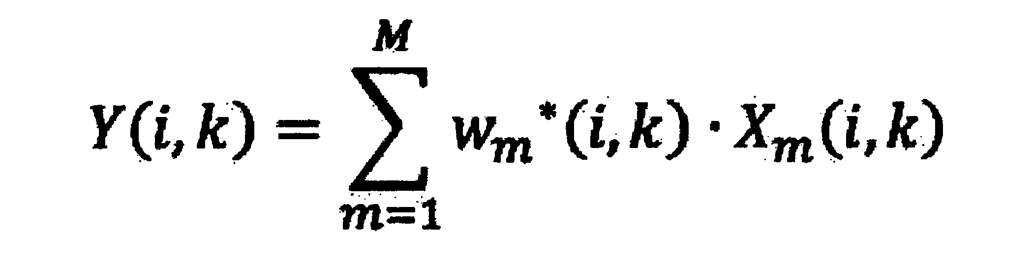
次に、図8を参照して、本実施形態に係る情報処理装置10の一連の処理の流れの一例について、特に、情報処理装置10が、複数の集音部それぞれの集音結果に基づき目的音(例えば、ユーザの音声)を取得する処理に着目して説明する。図8は、本実施形態に係る情報処理装置10の一連の処理の流れの一例を示したフローチャートである。 <1.4. Processing>
Next, referring to FIG. 8, an example of a flow of a series of processes of the
外部環境の音響は、複数の集音部110により集音されることで、情報処理装置10に取り込まれる。集音部110は、集音結果に基づく音響信号(アナログ信号)のゲインの調整し、AD変換によりアナログ信号からデジタル信号に変換したうえで、変換後の音響信号(デジタル信号)xm(n)を周波数分解部13に出力する。 (Step S101)
The sound of the external environment is taken into the
周波数分解部13は、集音部110から出力される音響信号xm(n)に対して、フレーム分割、所定の窓関数の適用、及び、時間-周波数変換等の処理を施すことで、当該音響信号xm(n)を周波数成分に分解する。そして、周波数分解部13は、音響信号xm(n)の各周波数成分Xm(i,k)を、後段に位置するフィルタ処理部17と、チャネルパワー推定部15とのそれぞれに出力する。これにより、複数の集音部110それぞれについて、音響信号xm(n)の各周波数成分Xm(i,k)が、フィルタ処理部17と、チャネルパワー推定部15とのそれぞれに出力されることとなる。 (Step S103)
The
チャネルパワー推定部15は、周波数分解部13から集音部110ごとに音響信号xm(n)の各周波数成分Xm(i,k)を取得する。次いで、チャネルパワー推定部15は、各集音部110それぞれに対応する音響信号xm(n)の各周波数成分Xm(i,k)に基づき、周波数ごとに、各集音部110のパワースペクトルを推定する。そして、チャネルパワー推定部15は、周波数ごとに、各集音部110のパワースペクトルPm(i,k)の推定結果をフィルタ推定部16に出力する。 (Step S105)
The channel
フィルタ推定部16は、チャネルパワー推定部15から出力される、周波数ごとの、各集音部110のパワースペクトルPm(i,k)の推定結果に基づき、後述するフィルタ処理部17が、フィルタリング処理を実行するためのフィルタ係数w(i,k)を算出する。 (Step S107)
Based on the estimation result of the power spectrum P m (i, k) of each sound collection unit 110 for each frequency output from the channel
フィルタ処理部17は、周波数分解部13から集音部110ごとに音響信号xm(n)の各周波数成分Xm(i,k)を取得する。また、フィルタ処理部17は、フィルタ推定部16から周波数ごとに算出されたフィルタ係数w(i,k)を取得する。フィルタ処理部17は、集音部110ごとの音響信号xm(n)の各周波数成分Xm(i,k)を入力信号として、取得した周波数ごとのフィルタ係数w(i,k)に基づき当該入力信号を重み付け加算することで、周波数ごとの出力信号Y(i,k)を生成する。そして、フィルタ処理部17は、周波数ごとに生成した出力信号Y(i,k)を、周波数合成部18に出力する。 (Step S109)
The
周波数合成部18は、フィルタ処理部17から出力される周波数ごとの出力信号Y(i,k)に対して、周波数-時間変換、所定の窓関数の適用、及びフレーム合成等の処理を施すことで、当該周波数ごとの出力信号Y(i,k)を合成する。これにより、各集音部110による集音結果が合成された音響信号y(n)が生成される。なお、周波数合成部18により生成された音響信号y(n)は、集音結果として、情報処理装置10により実行される各種処理(例えば、音声認識や音声通話等)に利用されることとなる。 (Step S111)
The
次に、実施例として、本実施形態に係る情報処理装置10の他の一態様について説明する。 <1.5. Example>
Next, another example of the
まず、実施例1として、図9~図11を参照して、図1に示した所謂ネックバンド型のウェアラブルデバイスのように、ユーザの首に装着され得るウェアラブルデバイスとして構成された情報処理装置の一例について説明する。 <1.5.1. Example 1: An example of a wearable device attached to the neck>
First, referring to FIG. 9 to FIG. 11, as an example 1, an information processing apparatus configured as a wearable device that can be worn on the user's neck like the so-called neckband type wearable device shown in FIG. An example will be described.
次に、実施例2として、図12~図15を参照して、頭部に装着され得るウェアラブルデバイスとして構成された情報処理装置の一例について説明する。 <1.5.2. Example 2: Example of wearable device worn on head>
Next, as a second embodiment, an example of an information processing apparatus configured as a wearable device that can be worn on the head will be described with reference to FIGS.
次に、実施例3として、図16及び図17を参照して、所謂スマートフォン等のような携帯型情報端末として構成された情報処理装置の一例について説明する。 <1.5.3. Example 3: Application example to portable information terminal>
Next, as Example 3, an example of an information processing apparatus configured as a portable information terminal such as a so-called smartphone will be described with reference to FIGS. 16 and 17.
次に、実施例4として、図18及び図19を参照して、腕に装着され得る、所謂時計型のウェアラブルデバイスとして構成された情報処理装置の一例について説明する。 <1.5.4. Example 4: Application example to watch-type wearable device>
Next, as Example 4, an example of an information processing apparatus configured as a so-called watch-type wearable device that can be worn on an arm will be described with reference to FIGS. 18 and 19.
次に、実施例5として、図20及び図21を参照して、動画像や静止画像を撮像可能な撮像装置として構成された情報処理装置の一例について説明する。 <1.5.5. Example 5: Application Example to Imaging Device>
Next, as Example 5, an example of an information processing apparatus configured as an imaging apparatus capable of capturing a moving image or a still image will be described with reference to FIGS. 20 and 21. FIG.
<2.1.概要>
続いて、本開示の第2の実施形態について説明する。前述した第1の実施形態に係る情報処理装置10では、複数の集音部それぞれの集音結果に基づき、観測レベル(即ち、集音された音響のレベル)のより小さい集音部の入力が優先されるようにフィルタリング処理を施すことで、風切音のようなランダムに発生する雑音の影響を低減していた。このような制御により、特に、風切音のようなランダムに発生する雑音の影響がより大きい場合に、より好適な態様で当該雑音の影響を緩和することが可能となる。 << 2. Second Embodiment >>
<2.1. Overview>
Subsequently, a second embodiment of the present disclosure will be described. In the
まず、図22を参照して、本実施形態に係る情報処理装置の機能構成の一例について説明する。図22は、本実施形態に係る情報処理装置の機能構成の一例を示したブロック図である。なお、以降の説明では、本実施形態に係る情報処理装置を、前述した第1の実施形態に係る情報処理装置10(図6参照)と明示的に区別するために、「情報処理装置60」と称する場合がある。 <2.2. Functional configuration>
First, an example of a functional configuration of the information processing apparatus according to the present embodiment will be described with reference to FIG. FIG. 22 is a block diagram illustrating an example of a functional configuration of the information processing apparatus according to the present embodiment. In the following description, in order to explicitly distinguish the information processing apparatus according to the present embodiment from the
続いて、非相関成分パワー推定部653が、周波数ごとに、各集音部110に対応する非相関成分のパワースペクトルQm(i,k)を算出する処理の詳細について説明する。 <2.3. Details of uncorrelated component power estimation unit>
Next, details of processing in which the decorrelation component


続いて、ランダムノイズパワー推定部655が、フィルタ係数w(i,k)の算出に用いられる、周波数ごとの、各集音部110のパワースペクトルWm(i,k)を決定する処理の詳細について説明する。 <2.4. Details of Random Noise Power Estimator>
Subsequently, details of the process in which the random noise
例えば、ランダムノイズパワー推定部655は、非相関成分のパワースペクトルQm(i,k)の推定結果を、パワースペクトルWm(i,k)としてフィルタ推定部66に出力してもよい。なお、この場合には、チャネルパワー推定部65は、入力パワー推定部651を含まなくてもよい。 (Case of applying the power spectrum Q m)
For example, the random noise
また、他の一例として、ランダムノイズパワー推定部655は、所定の条件に基づき、パワースペクトルPm(i,k)及びQm(i,k)それぞれの推定結果のうちのいずれかを選択的に、パワースペクトルWm(i,k)としてフィルタ推定部66に出力してもよい。 (Case where the power spectra P m and Q m are selectively switched)
As another example, the random noise
また、他の一例として、ランダムノイズパワー推定部655は、パワースペクトルPm(i,k)及びQm(i,k)それぞれの推定結果に基づき、パワースペクトルWm(i,k)を適応的に算出してもよい。 (Case where the power spectrum W m is calculated adaptively)
As another example, the random noise


以上説明したように、本実施形態に係る情報処理装置60は、複数の集音部110のうち少なくとも2以上の集音部110による集音結果と、フィルタ処理部17の出力信号Y(i,k)のフィードバックとに基づき、非相関成分のパワースペクトルQm(i,k)を推定する。そして、情報処理装置60は、非相関成分のパワースペクトルQm(i,k)の推定結果を、フィルタ係数w(i,k)の推定に利用する。このような構成により、情報処理装置60は、前述した第1の実施形態と同様に風切音等のランダムに発生する雑音の抑圧効果を維持し、さらに、ランダムに発生する雑音の影響が小さい場合において、より好適な態様で目的音を取得することが可能となる。 <2.5. Evaluation>
As described above, the
<3.1.概要>
続いて、本開示の第3の実施形態として、本開示に係る技術を、所謂マルチチャネルウィナーフィルタ(MWF:Multi Channel Wiener Filter)に適用した場合の一例について説明する。 << Third Embodiment >>
<3.1. Overview>
Subsequently, as a third embodiment of the present disclosure, an example in which the technique according to the present disclosure is applied to a so-called multi-channel Wiener filter (MWF) will be described.


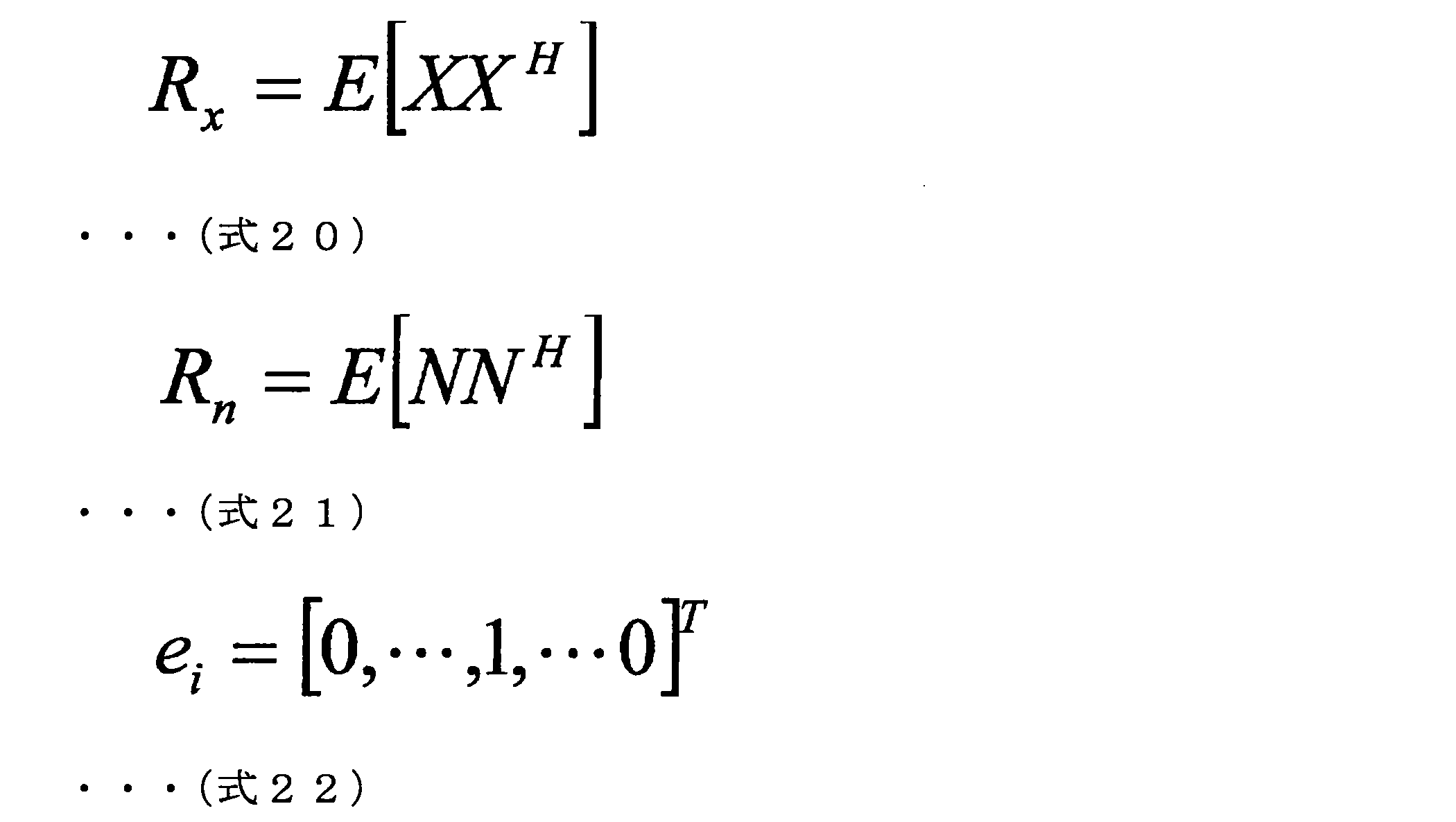
・・・(式22)
... (Formula 22)

図24を参照して、本実施形態に係る情報処理装置の機能構成の一例について説明する。図24は、本実施形態に係る情報処理装置の機能構成の一例を示したブロック図である。なお、以降の説明では、本実施形態に係る情報処理装置を、前述した他の実施形態に係る情報処理装置(例えば、情報処理装置10及び60)と明示的に区別するために、「情報処理装置70」と称する場合がある。 <3.2. Functional configuration>
With reference to FIG. 24, an example of a functional configuration of the information processing apparatus according to the present embodiment will be described. FIG. 24 is a block diagram illustrating an example of a functional configuration of the information processing apparatus according to the present embodiment. In the following description, in order to explicitly distinguish the information processing apparatus according to the present embodiment from the information processing apparatuses according to the other embodiments described above (for example, the
マルチチャネルウィナーフィルタ処理部76は、周波数分解部13から集音部110ごとに音響信号xm(n)の各周波数成分Xm(i,k)を取得する。また、マルチチャネルウィナーフィルタ処理部76は、後述するマルチチャネルウィナーフィルタ算出部75から、周波数ごとにマルチチャネルウィナーフィルタWmwf(i,k)の算出結果を取得する。なお、マルチチャネルウィナーフィルタWmwf(i,k)の算出方法については詳細を別途後述する。そして、マルチチャネルウィナーフィルタ処理部76は、集音部110ごとの音響信号xm(n)の各周波数成分Xm(i,k)を入力信号として、当該マルチチャネルウィナーフィルタWmwf(i,k)に基づくフィルタリング処理を施すことで、出力信号Sを周波数ごとに生成する。例えば、出力信号Sは、以下に(式24)として示す計算式で表される。なお、以下に示す(式24)では、フレーム番号i及び離散周波数番号kの記載を省略している。 (Multi-channel winner filter processing unit 76)
The multi-channel Wiener

周波数合成部77は、マルチチャネルウィナーフィルタ処理部76から周波数ごとに生成された出力信号Sを取得する。周波数合成部77は、取得した周波数ごとの出力信号Sを合成することで音響信号を生成する。なお、周波数合成部77による処理は、前述した第1及び第2の実施形態に係る周波数合成部18が、周波数ごとの出力信号Y(i,k)を合成することで音響信号y(n)を生成する処理と同様のため、詳細な説明は省略する。 (Frequency synthesizer 77)
The
続いて、チャネルパワー推定部71及びフィルタ推定部72の構成について説明する。チャネルパワー推定部71及びフィルタ推定部72は、前述した第1の実施形態に係る情報処理装置10と同様の仕組みを適用して構成してもよいし、第2の実施形態に係る情報処理装置60と同様の仕組みを適用して構成してもよい。そこで、以下にそれぞれの場合に着目して説明する。 (Channel
Next, the configuration of the channel
まず、前述した第1の実施形態に係る情報処理装置10(図6参照)と同様の仕組みを適用して、チャネルパワー推定部71及びフィルタ推定部72を構成する場合について説明する。この場合には、チャネルパワー推定部71及びフィルタ推定部72は、第1の実施形態に係るチャネルパワー推定部15及びフィルタ推定部16に相当することとなる。 (Configuration example 1 of channel
First, a case where the channel
続いて、前述した第2の実施形態に係る情報処理装置60(図22参照)と同様の仕組みを適用して、チャネルパワー推定部71及びフィルタ推定部72を構成する場合について説明する。この場合には、チャネルパワー推定部71及びフィルタ推定部72は、第2の実施形態に係るチャネルパワー推定部65及びフィルタ推定部66に相当することとなる。 (Configuration example 2 of channel
Subsequently, a case where the channel

入力相関行列算出部73は、周波数分解部13から集音部110ごとに音響信号xm(n)の各周波数成分Xm(i,k)を取得する。次いで、入力相関行列算出部73は、取得した各周波数成分Xm(i,k)を入力として、前述した(式20)に基づき、入力相関行列Rxを周波数ごとに算出する。そして、入力相関行列算出部73は、周波数ごとに算出した入力相関行列Rxをマルチチャネルウィナーフィルタ算出部75に出力する。 (Input correlation matrix calculation unit 73)
Input correlation
ノイズ相関行列算出部74は、周波数分解部13から集音部110ごとに音響信号xm(n)の各周波数成分Xm(i,k)を取得する。次いで、ノイズ相関行列算出部74は、音響信号xm(n)の各周波数成分Xm(i,k)の取得結果に基づき休止区間を特定する。次いで、ノイズ相関行列算出部74は、特定した休止区間における当該各周波数成分Xm(i,k)を入力として、前述した(式21)に基づき、ノイズ相関行列Rnを周波数ごとに算出する。そして、ノイズ相関行列算出部74は、周波数ごとに算出したノイズ相関行列Rnをマルチチャネルウィナーフィルタ算出部75に出力する。 (Noise correlation matrix calculation unit 74)
The noise correlation
マルチチャネルウィナーフィルタ算出部75は、フィルタ推定部72から、フィルタ係数w(i,k)に基づくフィルタGの算出結果を周波数ごとに取得する。また、マルチチャネルウィナーフィルタ算出部75は、入力相関行列算出部73から、入力相関行列Rxの算出結果を周波数ごとに取得する。また、マルチチャネルウィナーフィルタ算出部75は、ノイズ相関行列算出部74から、ノイズ相関行列Rnの算出結果を周波数ごとに取得する。次いで、マルチチャネルウィナーフィルタ算出部75は、周波数ごとに取得した、フィルタG、入力相関行列Rx、及びノイズ相関行列Rnそれぞれの算出結果に基づき、周波数ごとにマルチチャネルウィナーフィルタWmwf(i,k)を算出する。そして、マルチチャネルウィナーフィルタ算出部75は、マルチチャネルウィナーフィルタWmwf(i,k)の算出結果をマルチチャネルウィナーフィルタ処理部76に出力する。これにより、マルチチャネルウィナーフィルタ処理部76は、集音部110ごとの音響信号xm(n)の各周波数成分Xm(i,k)に対して、当該マルチチャネルウィナーフィルタWmwf(i,k)に基づきフィルタリング処理を施すことが可能となる。なお、マルチチャネルウィナーフィルタWmwf(i,k)の算出方法については、より詳細な内容について別途後述する。 (Multi-channel winner filter calculation unit 75)
The multi-channel winner
続いて、マルチチャネルウィナーフィルタWmwf(i,k)の算出方法についてより詳しく説明する。なお、本説明では、フレーム番号i及び離散周波数番号kの記載については省略するものとする。 <3.3. Details of multi-channel winner filter calculation method>
Next, the calculation method of the multi-channel winner filter W mwf (i, k) will be described in more detail. In this description, description of the frame number i and the discrete frequency number k is omitted.


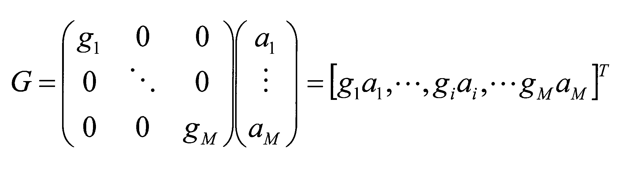
以上説明したように、本実施形態に係る情報処理装置70は、各集音部110それぞれに対応する音響信号xm(n)の各周波数成分Xm(i,k)に基づき、周波数ごとに、各集音部110のパワースペクトル(例えば、前述したパワースペクトルPm(i,k)やパワースペクトルWm(i,k))を推定する。そして、情報処理装置70は、当該パワースペクトルの推定結果に基づきフィルタ係数w(i,k)を推定し、当該フィルタ係数w(i,k)の推定結果をマルチチャネルウィナーフィルタWmwf(i,k)の算出に利用する。このような構成により、本実施形態に係る情報処理装置70は、複数の集音部110のうち、ランダムノイズの影響がより小さい集音部110をリファレンスマイクとして動的に選択することが可能となる。即ち、本実施形態に係る情報処理装置70に依れば、リファレンスマイクが固定的に設定される従来のマルチチャネルウィナーフィルタを適用した場合に比べて、ランダムノイズの影響をより低減し、ひいては、より好適な態様で目的音を抽出することが可能となる。 <3.4. Evaluation>
As described above, the
次に、図25を参照して、本開示の各実施形態に係る情報処理装置10(即ち、上述した信号処理装置11~14)のハードウェア構成の一例について説明する。図25は、本開示の各実施形態に係る情報処理装置10のハードウェア構成の一例を示した図である。 << 4. Hardware configuration >>
Next, an example of a hardware configuration of the information processing apparatus 10 (that is, the above-described signal processing apparatuses 11 to 14) according to each embodiment of the present disclosure will be described with reference to FIG. FIG. 25 is a diagram illustrating an example of a hardware configuration of the
以上、説明したように、本実施形態に係る情報処理装置10は、少なくとも一部に流線形の形状を有する凸部を備え、当該凸部の先端、または、当該先端の近傍に位置するように集音部110が支持される。このような構成とすることで、例えば、風切音、振動に伴う雑音、及び装置の装着に伴う衣擦れ等のようなランダムに発生する雑音の影響を緩和し、より好適な態様で目的音(例えば、ユーザの音声)を集音することが可能となる。 << 5. Conclusion >>
As described above, the
(1)
集音部と、
流線形の形状を有する凸部を少なくとも一部に備え、前記凸部の先端、または、当該先端の近傍に位置するように前記集音部を支持する支持部材と、
を備える、情報処理装置。
(2)
前記集音部である第1の集音部に加えて、当該第1の集音部とは異なる1以上の第2の集音部を備える、前記(1)に記載の情報処理装置。
(3)
前記支持部材は、複数の前記第2の集音部のそれぞれが、互いに異なる方向を向くように支持する、前記(2)に記載の情報処理装置。
(4)
前記支持部材は、ユーザの所定の部位に装着され、前記集音部と当該部位とが所定の位置関係となるように当該集音部を支持する、前記(1)に記載の情報処理装置。
(5)
前記部位は、首であり、
前記支持部材は、前記首に装着された場合に、前記凸部の先端が当該ユーザの略前方を向くように当該凸部が設けられている、
前記(4)に記載の情報処理装置。
(6)
前記集音部である第1の集音部に加えて、当該第1の集音部とは異なる複数の第2の集音部を備え、
複数の前記第2の集音部のうち少なくとも2以上の第2の集音部を、前記部位を基準として互いに略対称となる位置に支持する、
前記(4)または(5)に記載の情報処理装置。
(7)
前記第1の集音部と1以上の前記第2の集音部とのそれぞれにより集音された音響に基づき、前記第1の集音部に対して所定の方向から到来する音響に対する雑音成分を抑圧する信号処理部を備える、前記(2)に記載の情報処理装置。
(8)
前記信号処理部は、前記第1の集音部と1以上の前記第2の集音部とのそれぞれにより集音された音響に基づき、当該音響の周波数成分それぞれの信号レベルを推定し、当該信号レベルの推定結果に基づき、前記雑音成分を抑圧する、前記(7)に記載の情報処理装置。
(9)
前記信号処理部は、前記第1の集音部と1以上の前記第2の集音部とのうちの少なくとも複数の集音部それぞれにより集音された第1の音響と、従前の処理により前記雑音成分が抑圧された第2の音響との間の相関性に基づき、前記第1の音響に含まれる前記雑音成分を抑圧する、前記(7)に記載の情報処理装置。
(10)
前記支持部材は、前記複数の集音部のうち少なくとも2以上の集音部のそれぞれと、所定の音源との間の距離が互いに異なるように、当該複数の集音部を支持する、前記(9)に記載の情報処理装置。
(11)
前記支持部材は、前記複数の集音部のうち少なくとも2以上の集音部のそれぞれが、所定の音源に対して互いに異なる方向に位置するように、当該複数の集音部を支持する、前記(9)または(10)に記載の情報処理装置。
(12)
前記第1の集音部と1以上の前記第2の集音部とのうち一部の集音部により集音された音響を選択的に出力する出力制御部を備え、
前記出力制御部は、前記第1の集音部と1以上の前記第2の集音部とのそれぞれにより集音された音響に基づき、当該音響の周波数成分それぞれの信号レベルを推定し、当該信号レベルの推定結果に基づき、前記一部の集音部を選択する、
前記(2)に記載の情報処理装置。
(13)
前記出力制御部は、マルチチャネルウィナーフィルタを含み、当該マルチチャネルウィナーフィルタのリファレンスマイクを、前記信号レベルの推定結果に基づき選択する、前記(12)に記載の情報処理装置。
(14)
前記支持部材は、少なくとも一部に略矩形状の面を有する筐体であり、
前記筐体は、前記略矩形状の面の角を含む所定の領域中に前記凸部を有し、当該凸部の先端、または、当該先端の近傍に前記集音部を支持する、
前記(1)に記載の情報処理装置。
(15)
複数の前記集音部を備え、
前記筐体は、前記略矩形状の面の角のうち複数の角それぞれについて、当該角を含む所定の領域中に前記凸部を有し、当該凸部の先端、または、当該先端の近傍に前記集音部を支持する、前記(14)に記載の情報処理装置。
(16)
ユーザの腕に対して前記筐体を支持するバンド部を備え、
前記バンド部は、前記腕に装着された場合に、当該腕を基準として前記筐体と略対称となる位置に前記集音部とは異なる他の集音部を備える、
前記(14)または(15)に記載の情報処理装置。
(17)
前記支持部材は、ユーザの頭部に装着されるメガネ型のフレームであり、
前記フレームは、フロントの少なくとも一部に前記凸部を有し、当該凸部の先端、または、当該先端の近傍に前記集音部を支持する、
前記(1)に記載の情報処理装置。
(18)
前記フレームは、ブリッジ、または、当該ブリッジの近傍に前記凸部を有し、当該凸部の先端、または、当該先端の近傍に前記集音部を支持する、前記(17)に記載の情報処理装置。 The following configurations also belong to the technical scope of the present disclosure.
(1)
The sound collection section;
A support member for supporting the sound collection unit so as to be located at or near the tip of the protrusion, or at least part of the protrusion having a streamlined shape;
An information processing apparatus comprising:
(2)
The information processing apparatus according to (1), further including one or more second sound collecting units different from the first sound collecting unit in addition to the first sound collecting unit which is the sound collecting unit.
(3)
The information processing apparatus according to (2), wherein the support member supports each of the plurality of second sound collection units so as to face different directions.
(4)
The information processing apparatus according to (1), wherein the support member is attached to a predetermined part of a user and supports the sound collection unit so that the sound collection unit and the part have a predetermined positional relationship.
(5)
The part is a neck;
When the support member is attached to the neck, the convex portion is provided so that the tip of the convex portion faces substantially forward of the user.
The information processing apparatus according to (4).
(6)
In addition to the first sound collection unit that is the sound collection unit, a plurality of second sound collection units different from the first sound collection unit are provided,
Supporting at least two or more second sound collecting parts among the plurality of second sound collecting parts at positions that are substantially symmetrical with each other with respect to the part;
The information processing apparatus according to (4) or (5).
(7)
Based on the sound collected by each of the first sound collection unit and the one or more second sound collection units, a noise component for sound coming from a predetermined direction with respect to the first sound collection unit The information processing apparatus according to (2), further including a signal processing unit that suppresses noise.
(8)
The signal processing unit estimates a signal level of each frequency component of the sound based on the sound collected by each of the first sound collecting unit and the one or more second sound collecting units, and The information processing apparatus according to (7), wherein the noise component is suppressed based on a signal level estimation result.
(9)
The signal processing unit includes a first sound collected by each of at least a plurality of sound collection units of the first sound collection unit and the one or more second sound collection units, and a previous process. The information processing apparatus according to (7), wherein the noise component included in the first sound is suppressed based on a correlation with the second sound in which the noise component is suppressed.
(10)
The support member supports the plurality of sound collection units such that a distance between each of at least two or more of the plurality of sound collection units and a predetermined sound source is different from each other. The information processing apparatus according to 9).
(11)
The support member supports the plurality of sound collection units such that at least two or more of the plurality of sound collection units are located in different directions with respect to a predetermined sound source, (9) The information processing apparatus according to (10).
(12)
An output control unit that selectively outputs sound collected by a part of the first sound collecting unit and one or more second sound collecting units;
The output control unit estimates the signal level of each frequency component of the sound based on the sound collected by each of the first sound collecting unit and the one or more second sound collecting units, Based on the estimation result of the signal level, select the part of the sound collection unit,
The information processing apparatus according to (2).
(13)
The information processing apparatus according to (12), wherein the output control unit includes a multichannel Wiener filter, and selects a reference microphone of the multichannel Wiener filter based on the estimation result of the signal level.
(14)
The support member is a housing having a substantially rectangular surface at least in part,
The housing has the convex portion in a predetermined region including a corner of the substantially rectangular surface, and supports the sound collecting portion at the tip of the convex portion or in the vicinity of the tip.
The information processing apparatus according to (1).
(15)
A plurality of the sound collecting units;
The housing has the convex portion in a predetermined region including the corner for each of a plurality of corners of the substantially rectangular surface, and at or near the tip of the convex portion. The information processing apparatus according to (14), which supports the sound collection unit.
(16)
A band portion for supporting the housing with respect to a user's arm;
When the band portion is attached to the arm, the band portion includes another sound collecting portion different from the sound collecting portion at a position that is substantially symmetrical with the housing with respect to the arm.
The information processing apparatus according to (14) or (15).
(17)
The support member is a glasses-type frame attached to the user's head,
The frame has the convex portion on at least a part of the front, and supports the sound collecting portion at the tip of the convex portion or in the vicinity of the tip.
The information processing apparatus according to (1).
(18)
The information processing according to (17), wherein the frame has the convex portion in the vicinity of the bridge or the bridge, and supports the sound collecting portion in the front end of the convex portion or in the vicinity of the front end. apparatus.
13 周波数分解部
15 チャネルパワー推定部
16 フィルタ推定部
17 フィルタ処理部
18 周波数合成部
110~113 集音部
60 情報処理装置
65 チャネルパワー推定部
651 入力パワー推定部
653 非相関成分パワー推定部
655 ランダムノイズパワー推定部
66 フィルタ推定部 DESCRIPTION OF
Claims (18)
- 集音部と、
流線形の形状を有する凸部を少なくとも一部に備え、前記凸部の先端、または、当該先端の近傍に位置するように前記集音部を支持する支持部材と、
を備える、情報処理装置。 The sound collection section;
A support member for supporting the sound collection unit so as to be located at or near the tip of the protrusion, or at least part of the protrusion having a streamlined shape;
An information processing apparatus comprising: - 前記集音部である第1の集音部に加えて、当該第1の集音部とは異なる1以上の第2の集音部を備える、請求項1に記載の情報処理装置。 The information processing apparatus according to claim 1, further comprising one or more second sound collecting units different from the first sound collecting unit in addition to the first sound collecting unit which is the sound collecting unit.
- 前記支持部材は、複数の前記第2の集音部のそれぞれが、互いに異なる方向を向くように支持する、請求項2に記載の情報処理装置。 The information processing apparatus according to claim 2, wherein the support member supports each of the plurality of second sound collection units so as to face different directions.
- 前記支持部材は、ユーザの所定の部位に装着され、前記集音部と当該部位とが所定の位置関係となるように当該集音部を支持する、請求項1に記載の情報処理装置。 The information processing apparatus according to claim 1, wherein the support member is attached to a predetermined part of a user and supports the sound collection unit so that the sound collection unit and the part have a predetermined positional relationship.
- 前記部位は、首であり、
前記支持部材は、前記首に装着された場合に、前記凸部の先端が当該ユーザの略前方を向くように当該凸部が設けられている、
請求項4に記載の情報処理装置。 The part is a neck;
When the support member is attached to the neck, the convex portion is provided so that the tip of the convex portion faces substantially forward of the user.
The information processing apparatus according to claim 4. - 前記集音部である第1の集音部に加えて、当該第1の集音部とは異なる複数の第2の集音部を備え、
複数の前記第2の集音部のうち少なくとも2以上の第2の集音部を、前記部位を基準として互いに略対称となる位置に支持する、
請求項4に記載の情報処理装置。 In addition to the first sound collection unit that is the sound collection unit, a plurality of second sound collection units different from the first sound collection unit are provided,
Supporting at least two or more second sound collecting parts among the plurality of second sound collecting parts at positions that are substantially symmetrical with each other with respect to the part;
The information processing apparatus according to claim 4. - 前記第1の集音部と1以上の前記第2の集音部とのそれぞれにより集音された音響に基づき、前記第1の集音部に対して所定の方向から到来する音響に対する雑音成分を抑圧する信号処理部を備える、請求項2に記載の情報処理装置。 Based on the sound collected by each of the first sound collection unit and the one or more second sound collection units, a noise component for sound coming from a predetermined direction with respect to the first sound collection unit The information processing apparatus according to claim 2, further comprising: a signal processing unit that suppresses noise.
- 前記信号処理部は、前記第1の集音部と1以上の前記第2の集音部とのそれぞれにより集音された音響に基づき、当該音響の周波数成分それぞれの信号レベルを推定し、当該信号レベルの推定結果に基づき、前記雑音成分を抑圧する、請求項7に記載の情報処理装置。 The signal processing unit estimates a signal level of each frequency component of the sound based on the sound collected by each of the first sound collecting unit and the one or more second sound collecting units, and The information processing apparatus according to claim 7, wherein the noise component is suppressed based on a signal level estimation result.
- 前記信号処理部は、前記第1の集音部と1以上の前記第2の集音部とのうちの少なくとも複数の集音部それぞれにより集音された第1の音響と、従前の処理により前記雑音成分が抑圧された第2の音響との間の相関性に基づき、前記第1の音響に含まれる前記雑音成分を抑圧する、請求項7に記載の情報処理装置。 The signal processing unit includes a first sound collected by each of at least a plurality of sound collection units of the first sound collection unit and the one or more second sound collection units, and a previous process. The information processing apparatus according to claim 7, wherein the noise component included in the first sound is suppressed based on a correlation with the second sound in which the noise component is suppressed.
- 前記支持部材は、前記複数の集音部のうち少なくとも2以上の集音部のそれぞれと、所定の音源との間の距離が互いに異なるように、当該複数の集音部を支持する、請求項9に記載の情報処理装置。 The said support member supports the said several sound collection part so that the distance between each of at least 2 or more sound collection parts of the said several sound collection parts and a predetermined sound source may mutually differ. 9. The information processing apparatus according to 9.
- 前記支持部材は、前記複数の集音部のうち少なくとも2以上の集音部のそれぞれが、所定の音源に対して互いに異なる方向に位置するように、当該複数の集音部を支持する、請求項9に記載の情報処理装置。 The support member supports the plurality of sound collection units such that at least two or more of the plurality of sound collection units are located in different directions with respect to a predetermined sound source. Item 10. The information processing device according to Item 9.
- 前記第1の集音部と1以上の前記第2の集音部とを含む複数の集音部のうち、一部の集音部により集音された音響を選択的に出力する出力制御部を備え、
前記出力制御部は、前記第1の集音部と1以上の前記第2の集音部とのそれぞれにより集音された音響に基づき、当該音響の周波数成分それぞれの信号レベルを推定し、当該信号レベルの推定結果に基づき、前記一部の集音部を選択する、
請求項2に記載の情報処理装置。 An output control unit that selectively outputs the sound collected by some of the sound collecting units among the plurality of sound collecting units including the first sound collecting unit and the one or more second sound collecting units. With
The output control unit estimates the signal level of each frequency component of the sound based on the sound collected by each of the first sound collecting unit and the one or more second sound collecting units, Based on the estimation result of the signal level, select the part of the sound collection unit,
The information processing apparatus according to claim 2. - 前記出力制御部は、マルチチャネルウィナーフィルタを含み、当該マルチチャネルウィナーフィルタのリファレンスマイクを、前記信号レベルの推定結果に基づき選択する、請求項12に記載の情報処理装置。 The information processing apparatus according to claim 12, wherein the output control unit includes a multichannel winner filter, and selects a reference microphone of the multichannel winner filter based on the estimation result of the signal level.
- 前記支持部材は、少なくとも一部に略矩形状の面を有する筐体であり、
前記筐体は、前記略矩形状の面の角を含む所定の領域中に前記凸部を有し、当該凸部の先端、または、当該先端の近傍に前記集音部を支持する、
請求項1に記載の情報処理装置。 The support member is a housing having a substantially rectangular surface at least in part,
The housing has the convex portion in a predetermined region including a corner of the substantially rectangular surface, and supports the sound collecting portion at the tip of the convex portion or in the vicinity of the tip.
The information processing apparatus according to claim 1. - 複数の前記集音部を備え、
前記筐体は、前記略矩形状の面の角のうち複数の角それぞれについて、当該角を含む所定の領域中に前記凸部を有し、当該凸部の先端、または、当該先端の近傍に前記集音部を支持する、請求項14に記載の情報処理装置。 A plurality of the sound collecting units;
The housing has the convex portion in a predetermined region including the corner for each of a plurality of corners of the substantially rectangular surface, and at or near the tip of the convex portion. The information processing apparatus according to claim 14, wherein the information collection unit is supported. - ユーザの腕に対して前記筐体を支持するバンド部を備え、
前記バンド部は、前記腕に装着された場合に、当該腕を基準として前記筐体と略対称となる位置に前記集音部とは異なる他の集音部を備える、
請求項14に記載の情報処理装置。 A band portion for supporting the housing with respect to a user's arm;
When the band portion is attached to the arm, the band portion includes another sound collecting portion different from the sound collecting portion at a position that is substantially symmetrical with the housing with respect to the arm.
The information processing apparatus according to claim 14. - 前記支持部材は、ユーザの頭部に装着されるメガネ型のフレームであり、
前記フレームは、フロントの少なくとも一部に前記凸部を有し、当該凸部の先端、または、当該先端の近傍に前記集音部を支持する、
請求項1に記載の情報処理装置。 The support member is a glasses-type frame attached to the user's head,
The frame has the convex portion on at least a part of the front, and supports the sound collecting portion at the tip of the convex portion or in the vicinity of the tip.
The information processing apparatus according to claim 1. - 前記フレームは、ブリッジ、または、当該ブリッジの近傍に前記凸部を有し、当該凸部の先端、または、当該先端の近傍に前記集音部を支持する、請求項17に記載の情報処理装置。 The information processing apparatus according to claim 17, wherein the frame has the convex portion in the vicinity of the bridge or the bridge, and supports the sound collection unit in a front end of the convex portion or in the vicinity of the front end. .
Priority Applications (10)
| Application Number | Priority Date | Filing Date | Title |
|---|---|---|---|
| RU2018112178A RU2727883C2 (en) | 2015-10-13 | 2016-10-06 | Information processing device |
| US15/766,241 US10565976B2 (en) | 2015-10-13 | 2016-10-06 | Information processing device |
| KR1020187008290A KR102524931B1 (en) | 2015-10-13 | 2016-10-06 | information processing device |
| JP2017545183A JP6496941B2 (en) | 2015-10-13 | 2016-10-06 | Information processing device |
| CN201680058465.XA CN108141654B (en) | 2015-10-13 | 2016-10-06 | Information processing apparatus |
| BR112018007055-6A BR112018007055A2 (en) | 2015-10-13 | 2016-10-06 | Information processor |
| EP16855346.9A EP3364663B1 (en) | 2015-10-13 | 2016-10-06 | Information processing device |
| EP19168684.9A EP3544311B1 (en) | 2015-10-13 | 2016-10-06 | Information processing device |
| PH12018500760A PH12018500760A1 (en) | 2015-10-13 | 2018-04-05 | Information processing device |
| US16/517,365 US11232777B2 (en) | 2015-10-13 | 2019-07-19 | Information processing device |
Applications Claiming Priority (8)
| Application Number | Priority Date | Filing Date | Title |
|---|---|---|---|
| JP2015-201723 | 2015-10-13 | ||
| JP2015201723 | 2015-10-13 | ||
| JP2016-133593 | 2016-07-05 | ||
| JP2016133593 | 2016-07-05 | ||
| JPPCT/JP2016/073655 | 2016-08-10 | ||
| PCT/JP2016/073655 WO2017064914A1 (en) | 2015-10-13 | 2016-08-10 | Information-processing device |
| JP2016177402 | 2016-09-12 | ||
| JP2016-177402 | 2016-09-12 |
Related Parent Applications (1)
| Application Number | Title | Priority Date | Filing Date |
|---|---|---|---|
| PCT/JP2016/073655 Continuation-In-Part WO2017064914A1 (en) | 2015-10-13 | 2016-08-10 | Information-processing device |
Related Child Applications (2)
| Application Number | Title | Priority Date | Filing Date |
|---|---|---|---|
| US15/766,241 A-371-Of-International US10565976B2 (en) | 2015-10-13 | 2016-10-06 | Information processing device |
| US16/517,365 Continuation US11232777B2 (en) | 2015-10-13 | 2019-07-19 | Information processing device |
Publications (1)
| Publication Number | Publication Date |
|---|---|
| WO2017065092A1 true WO2017065092A1 (en) | 2017-04-20 |
Family
ID=58517591
Family Applications (1)
| Application Number | Title | Priority Date | Filing Date |
|---|---|---|---|
| PCT/JP2016/079855 WO2017065092A1 (en) | 2015-10-13 | 2016-10-06 | Information processing device |
Country Status (3)
| Country | Link |
|---|---|
| US (1) | US11232777B2 (en) |
| CN (1) | CN110493692B (en) |
| WO (1) | WO2017065092A1 (en) |
Cited By (4)
| Publication number | Priority date | Publication date | Assignee | Title |
|---|---|---|---|---|
| WO2018051663A1 (en) * | 2016-09-13 | 2018-03-22 | ソニー株式会社 | Sound source position estimating device and wearable device |
| WO2018207453A1 (en) * | 2017-05-08 | 2018-11-15 | ソニー株式会社 | Information processing device |
| WO2019128390A1 (en) * | 2017-12-28 | 2019-07-04 | 安克创新科技股份有限公司 | Neck ring bluetooth headset |
| JPWO2022190245A1 (en) * | 2021-03-10 | 2022-09-15 |
Families Citing this family (1)
| Publication number | Priority date | Publication date | Assignee | Title |
|---|---|---|---|---|
| CN113421566B (en) * | 2021-08-20 | 2021-11-12 | 航天科工通信技术研究院有限责任公司 | Portable voice noise reduction device based on wind noise |
Citations (9)
| Publication number | Priority date | Publication date | Assignee | Title |
|---|---|---|---|---|
| JPS51248Y1 (en) * | 1971-05-26 | 1976-01-07 | ||
| US5793875A (en) * | 1996-04-22 | 1998-08-11 | Cardinal Sound Labs, Inc. | Directional hearing system |
| JP2005534269A (en) * | 2002-07-26 | 2005-11-10 | オークレイ・インコーポレイテッド | Wireless interactive headset |
| JP2007519342A (en) * | 2004-01-09 | 2007-07-12 | コス コーポレイション | Hands-free personal communication device |
| JP2008507926A (en) * | 2004-07-22 | 2008-03-13 | ソフトマックス,インク | Headset for separating audio signals in noisy environments |
| JP2012133250A (en) * | 2010-12-24 | 2012-07-12 | Sony Corp | Sound information display apparatus, method and program |
| JP2014023141A (en) * | 2012-07-23 | 2014-02-03 | Satoru Katsumata | Holder for carrying mobile information terminal |
| JP2014045236A (en) * | 2012-08-24 | 2014-03-13 | Akoo:Kk | Surface sound pressure measurement microphone with windbreak layer |
| WO2015003220A1 (en) * | 2013-07-12 | 2015-01-15 | Wolfson Dynamic Hearing Pty Ltd | Wind noise reduction |
Family Cites Families (34)
| Publication number | Priority date | Publication date | Assignee | Title |
|---|---|---|---|---|
| US5251263A (en) * | 1992-05-22 | 1993-10-05 | Andrea Electronics Corporation | Adaptive noise cancellation and speech enhancement system and apparatus therefor |
| CN1643571A (en) * | 2002-03-27 | 2005-07-20 | 艾黎弗公司 | Nicrophone and voice activity detection (vad) configurations for use with communication systems |
| WO2004016037A1 (en) * | 2002-08-13 | 2004-02-19 | Nanyang Technological University | Method of increasing speech intelligibility and device therefor |
| US7711110B2 (en) | 2007-03-16 | 2010-05-04 | Midas Technology, Llc | Universal speakerphone with adaptable interface |
| US8411880B2 (en) | 2008-01-29 | 2013-04-02 | Qualcomm Incorporated | Sound quality by intelligently selecting between signals from a plurality of microphones |
| JP4506873B2 (en) * | 2008-05-08 | 2010-07-21 | ソニー株式会社 | Signal processing apparatus and signal processing method |
| US20110317858A1 (en) * | 2008-05-28 | 2011-12-29 | Yat Yiu Cheung | Hearing aid apparatus |
| US20090296966A1 (en) * | 2008-05-28 | 2009-12-03 | Yat Yiu Cheung | Hearing Kit |
| US8842848B2 (en) * | 2009-09-18 | 2014-09-23 | Aliphcom | Multi-modal audio system with automatic usage mode detection and configuration capability |
| US8897455B2 (en) * | 2010-02-18 | 2014-11-25 | Qualcomm Incorporated | Microphone array subset selection for robust noise reduction |
| JP2012203122A (en) | 2011-03-24 | 2012-10-22 | Panasonic Corp | Voice selection device, and media device and hands-free talking device using the same |
| CN102300140B (en) * | 2011-08-10 | 2013-12-18 | 歌尔声学股份有限公司 | Speech enhancing method and device of communication earphone and noise reduction communication earphone |
| JP5772447B2 (en) | 2011-09-27 | 2015-09-02 | 富士ゼロックス株式会社 | Speech analyzer |
| US10223710B2 (en) * | 2013-01-04 | 2019-03-05 | Visa International Service Association | Wearable intelligent vision device apparatuses, methods and systems |
| EP2842348B1 (en) | 2012-04-27 | 2016-07-20 | Sony Mobile Communications AB | Noise suppression based on correlation of sound in a microphone array |
| EP2893532B1 (en) | 2012-09-03 | 2021-03-24 | Fraunhofer-Gesellschaft zur Förderung der Angewandten Forschung e.V. | Apparatus and method for providing an informed multichannel speech presence probability estimation |
| CN202998463U (en) * | 2012-12-11 | 2013-06-12 | 启通科技有限公司 | Neck hanging hearing aid |
| JP6174856B2 (en) * | 2012-12-27 | 2017-08-02 | キヤノン株式会社 | Noise suppression device, control method thereof, and program |
| KR101498087B1 (en) | 2013-02-21 | 2015-03-03 | 엘지전자 주식회사 | Bluetooth headset |
| EP2973556B1 (en) * | 2013-03-13 | 2018-07-11 | Kopin Corporation | Noise cancelling microphone apparatus |
| EP2840807A1 (en) | 2013-08-19 | 2015-02-25 | Oticon A/s | External microphone array and hearing aid using it |
| US20160205453A1 (en) | 2013-08-23 | 2016-07-14 | Binauric SE | External speaker/microphone apparatus for use with an electrical device for providing audio signals and/or for voice communication |
| KR102145735B1 (en) * | 2013-11-07 | 2020-08-19 | 엘지전자 주식회사 | Mobile terminal and method for controlling the same |
| CN103700373A (en) * | 2013-12-21 | 2014-04-02 | 刘兴超 | Sound denoising system and denoising processing method of wearable equipment |
| EP2919482B1 (en) | 2014-03-13 | 2019-11-06 | LG Electronics Inc. | Wireless ear piece |
| KR102091520B1 (en) | 2014-03-25 | 2020-03-20 | 엘지전자 주식회사 | Mobile terminal |
| KR102127390B1 (en) | 2014-06-10 | 2020-06-26 | 엘지전자 주식회사 | Wireless receiver and method for controlling the same |
| US20150382096A1 (en) * | 2014-06-25 | 2015-12-31 | Roam, Llc | Headphones with pendant audio processing |
| US9900688B2 (en) | 2014-06-26 | 2018-02-20 | Intel Corporation | Beamforming audio with wearable device microphones |
| KR101545147B1 (en) * | 2014-09-15 | 2015-08-24 | 주식회사 블루콤 | Bluetooth stereo headset including manners call function |
| US9654868B2 (en) * | 2014-12-05 | 2017-05-16 | Stages Llc | Multi-channel multi-domain source identification and tracking |
| CN204993794U (en) * | 2015-09-15 | 2016-01-20 | 新科实业有限公司 | Sound system of device of making an uproar falls in area initiative |
| EP3544311B1 (en) | 2015-10-13 | 2022-11-30 | Sony Group Corporation | Information processing device |
| US10368162B2 (en) | 2015-10-30 | 2019-07-30 | Google Llc | Method and apparatus for recreating directional cues in beamformed audio |
-
2016
- 2016-10-06 CN CN201910827384.7A patent/CN110493692B/en active Active
- 2016-10-06 WO PCT/JP2016/079855 patent/WO2017065092A1/en active Application Filing
-
2019
- 2019-07-19 US US16/517,365 patent/US11232777B2/en active Active
Patent Citations (9)
| Publication number | Priority date | Publication date | Assignee | Title |
|---|---|---|---|---|
| JPS51248Y1 (en) * | 1971-05-26 | 1976-01-07 | ||
| US5793875A (en) * | 1996-04-22 | 1998-08-11 | Cardinal Sound Labs, Inc. | Directional hearing system |
| JP2005534269A (en) * | 2002-07-26 | 2005-11-10 | オークレイ・インコーポレイテッド | Wireless interactive headset |
| JP2007519342A (en) * | 2004-01-09 | 2007-07-12 | コス コーポレイション | Hands-free personal communication device |
| JP2008507926A (en) * | 2004-07-22 | 2008-03-13 | ソフトマックス,インク | Headset for separating audio signals in noisy environments |
| JP2012133250A (en) * | 2010-12-24 | 2012-07-12 | Sony Corp | Sound information display apparatus, method and program |
| JP2014023141A (en) * | 2012-07-23 | 2014-02-03 | Satoru Katsumata | Holder for carrying mobile information terminal |
| JP2014045236A (en) * | 2012-08-24 | 2014-03-13 | Akoo:Kk | Surface sound pressure measurement microphone with windbreak layer |
| WO2015003220A1 (en) * | 2013-07-12 | 2015-01-15 | Wolfson Dynamic Hearing Pty Ltd | Wind noise reduction |
Non-Patent Citations (1)
| Title |
|---|
| TOBY CHRISTIAN LAWIN-ORE ET AL.: "Reference Microphone Selection for MWF-based Noise Reduction Using Distributed Microphone Arrays", PROC. 10.ITG SYMPOSIUM ON SPEECH COMMUNICATION, 25 September 2012 (2012-09-25), XP055375849, ISBN: 978-3-8007-3455-9 * |
Cited By (11)
| Publication number | Priority date | Publication date | Assignee | Title |
|---|---|---|---|---|
| WO2018051663A1 (en) * | 2016-09-13 | 2018-03-22 | ソニー株式会社 | Sound source position estimating device and wearable device |
| JPWO2018051663A1 (en) * | 2016-09-13 | 2019-06-24 | ソニー株式会社 | Sound source position estimation device and wearable device |
| US11402461B2 (en) | 2016-09-13 | 2022-08-02 | Sony Corporation | Sound source position estimation device and wearable device |
| WO2018207453A1 (en) * | 2017-05-08 | 2018-11-15 | ソニー株式会社 | Information processing device |
| JPWO2018207453A1 (en) * | 2017-05-08 | 2020-03-12 | ソニー株式会社 | Information processing device |
| JP7103353B2 (en) | 2017-05-08 | 2022-07-20 | ソニーグループ株式会社 | Information processing equipment |
| US11468884B2 (en) | 2017-05-08 | 2022-10-11 | Sony Corporation | Method, apparatus and computer program for detecting voice uttered from a particular position |
| WO2019128390A1 (en) * | 2017-12-28 | 2019-07-04 | 安克创新科技股份有限公司 | Neck ring bluetooth headset |
| JPWO2022190245A1 (en) * | 2021-03-10 | 2022-09-15 | ||
| WO2022190245A1 (en) * | 2021-03-10 | 2022-09-15 | 三菱電機株式会社 | Noise suppression device, noise suppression method, and noise suppression program |
| JP7345702B2 (en) | 2021-03-10 | 2023-09-15 | 三菱電機株式会社 | Noise suppression device, noise suppression method, and noise suppression program |
Also Published As
| Publication number | Publication date |
|---|---|
| US20190341019A1 (en) | 2019-11-07 |
| CN110493692B (en) | 2022-01-25 |
| US11232777B2 (en) | 2022-01-25 |
| CN110493692A (en) | 2019-11-22 |
Similar Documents
| Publication | Publication Date | Title |
|---|---|---|
| WO2017065092A1 (en) | Information processing device | |
| CN108600907B (en) | Method for positioning sound source, hearing device and hearing system | |
| JP2019110593A (en) | Information processing apparatus | |
| CN108370471A (en) | Distributed audio captures and mixing | |
| US20160112817A1 (en) | Head wearable acoustic system with noise canceling microphone geometry apparatuses and methods | |
| US11146897B2 (en) | Method of operating a hearing aid system and a hearing aid system | |
| JP2017092732A (en) | Auditory supporting system and auditory supporting device | |
| WO2016100460A1 (en) | Systems and methods for source localization and separation | |
| US10186278B2 (en) | Microphone array noise suppression using noise field isotropy estimation | |
| TW202242855A (en) | Acoustic device | |
| JP2007336460A (en) | Listening device | |
| WO2016147020A1 (en) | Microphone array speech enhancement | |
| CN109417669A (en) | For obtaining device, the method and computer program of audio signal | |
| WO2017064914A1 (en) | Information-processing device | |
| CN110890100A (en) | Voice enhancement method, multimedia data acquisition method, multimedia data playing method, device and monitoring system | |
| CN114708881A (en) | Directional selectable pickup method based on double microphones, electronic equipment and storage medium | |
| WO2022226696A1 (en) | Open earphone | |
| D'Olne et al. | Model-based beamforming for wearable microphone arrays | |
| US11937047B1 (en) | Ear-worn device with neural network for noise reduction and/or spatial focusing using multiple input audio signals | |
| CN115665606B (en) | Sound reception method and sound reception device based on four microphones | |
| US11812224B2 (en) | Hearing device comprising a delayless adaptive filter | |
| US11683634B1 (en) | Joint suppression of interferences in audio signal | |
| US20220240026A1 (en) | Hearing device comprising a noise reduction system | |
| CN115529537A (en) | Differential beam forming method, device and storage medium | |
| JP2023554206A (en) | open type sound equipment |
Legal Events
| Date | Code | Title | Description |
|---|---|---|---|
| 121 | Ep: the epo has been informed by wipo that ep was designated in this application |
Ref document number: 16855346 Country of ref document: EP Kind code of ref document: A1 |
|
| ENP | Entry into the national phase |
Ref document number: 2017545183 Country of ref document: JP Kind code of ref document: A |
|
| ENP | Entry into the national phase |
Ref document number: 20187008290 Country of ref document: KR Kind code of ref document: A |
|
| WWE | Wipo information: entry into national phase |
Ref document number: 15766241 Country of ref document: US Ref document number: 12018500760 Country of ref document: PH Ref document number: 2018112178 Country of ref document: RU |
|
| NENP | Non-entry into the national phase |
Ref country code: DE |
|
| REG | Reference to national code |
Ref country code: BR Ref legal event code: B01A Ref document number: 112018007055 Country of ref document: BR |
|
| ENP | Entry into the national phase |
Ref document number: 112018007055 Country of ref document: BR Kind code of ref document: A2 Effective date: 20180406 |