JP6496941B2 - Information processing device - Google Patents
Information processing device Download PDFInfo
- Publication number
- JP6496941B2 JP6496941B2 JP2017545183A JP2017545183A JP6496941B2 JP 6496941 B2 JP6496941 B2 JP 6496941B2 JP 2017545183 A JP2017545183 A JP 2017545183A JP 2017545183 A JP2017545183 A JP 2017545183A JP 6496941 B2 JP6496941 B2 JP 6496941B2
- Authority
- JP
- Japan
- Prior art keywords
- information processing
- processing apparatus
- unit
- sound
- sound collection
- Prior art date
- Legal status (The legal status is an assumption and is not a legal conclusion. Google has not performed a legal analysis and makes no representation as to the accuracy of the status listed.)
- Active
Links
Images


Classifications
-
- G—PHYSICS
- G10—MUSICAL INSTRUMENTS; ACOUSTICS
- G10K—SOUND-PRODUCING DEVICES; METHODS OR DEVICES FOR PROTECTING AGAINST, OR FOR DAMPING, NOISE OR OTHER ACOUSTIC WAVES IN GENERAL; ACOUSTICS NOT OTHERWISE PROVIDED FOR
- G10K11/00—Methods or devices for transmitting, conducting or directing sound in general; Methods or devices for protecting against, or for damping, noise or other acoustic waves in general
- G10K11/16—Methods or devices for protecting against, or for damping, noise or other acoustic waves in general
- G10K11/175—Methods or devices for protecting against, or for damping, noise or other acoustic waves in general using interference effects; Masking sound
- G10K11/178—Methods or devices for protecting against, or for damping, noise or other acoustic waves in general using interference effects; Masking sound by electro-acoustically regenerating the original acoustic waves in anti-phase
- G10K11/1781—Methods or devices for protecting against, or for damping, noise or other acoustic waves in general using interference effects; Masking sound by electro-acoustically regenerating the original acoustic waves in anti-phase characterised by the analysis of input or output signals, e.g. frequency range, modes, transfer functions
- G10K11/17821—Methods or devices for protecting against, or for damping, noise or other acoustic waves in general using interference effects; Masking sound by electro-acoustically regenerating the original acoustic waves in anti-phase characterised by the analysis of input or output signals, e.g. frequency range, modes, transfer functions characterised by the analysis of the input signals only
- G10K11/17823—Reference signals, e.g. ambient acoustic environment
-
- G—PHYSICS
- G10—MUSICAL INSTRUMENTS; ACOUSTICS
- G10K—SOUND-PRODUCING DEVICES; METHODS OR DEVICES FOR PROTECTING AGAINST, OR FOR DAMPING, NOISE OR OTHER ACOUSTIC WAVES IN GENERAL; ACOUSTICS NOT OTHERWISE PROVIDED FOR
- G10K11/00—Methods or devices for transmitting, conducting or directing sound in general; Methods or devices for protecting against, or for damping, noise or other acoustic waves in general
- G10K11/16—Methods or devices for protecting against, or for damping, noise or other acoustic waves in general
- G10K11/175—Methods or devices for protecting against, or for damping, noise or other acoustic waves in general using interference effects; Masking sound
- G10K11/178—Methods or devices for protecting against, or for damping, noise or other acoustic waves in general using interference effects; Masking sound by electro-acoustically regenerating the original acoustic waves in anti-phase
- G10K11/1785—Methods, e.g. algorithms; Devices
- G10K11/17853—Methods, e.g. algorithms; Devices of the filter
-
- G—PHYSICS
- G10—MUSICAL INSTRUMENTS; ACOUSTICS
- G10L—SPEECH ANALYSIS OR SYNTHESIS; SPEECH RECOGNITION; SPEECH OR VOICE PROCESSING; SPEECH OR AUDIO CODING OR DECODING
- G10L21/00—Processing of the speech or voice signal to produce another audible or non-audible signal, e.g. visual or tactile, in order to modify its quality or its intelligibility
- G10L21/02—Speech enhancement, e.g. noise reduction or echo cancellation
- G10L21/0208—Noise filtering
-
- H—ELECTRICITY
- H04—ELECTRIC COMMUNICATION TECHNIQUE
- H04M—TELEPHONIC COMMUNICATION
- H04M1/00—Substation equipment, e.g. for use by subscribers
- H04M1/02—Constructional features of telephone sets
- H04M1/03—Constructional features of telephone transmitters or receivers, e.g. telephone hand-sets
-
- H—ELECTRICITY
- H04—ELECTRIC COMMUNICATION TECHNIQUE
- H04R—LOUDSPEAKERS, MICROPHONES, GRAMOPHONE PICK-UPS OR LIKE ACOUSTIC ELECTROMECHANICAL TRANSDUCERS; DEAF-AID SETS; PUBLIC ADDRESS SYSTEMS
- H04R1/00—Details of transducers, loudspeakers or microphones
- H04R1/02—Casings; Cabinets ; Supports therefor; Mountings therein
- H04R1/025—Arrangements for fixing loudspeaker transducers, e.g. in a box, furniture
-
- H—ELECTRICITY
- H04—ELECTRIC COMMUNICATION TECHNIQUE
- H04R—LOUDSPEAKERS, MICROPHONES, GRAMOPHONE PICK-UPS OR LIKE ACOUSTIC ELECTROMECHANICAL TRANSDUCERS; DEAF-AID SETS; PUBLIC ADDRESS SYSTEMS
- H04R3/00—Circuits for transducers, loudspeakers or microphones
- H04R3/005—Circuits for transducers, loudspeakers or microphones for combining the signals of two or more microphones
-
- G—PHYSICS
- G10—MUSICAL INSTRUMENTS; ACOUSTICS
- G10K—SOUND-PRODUCING DEVICES; METHODS OR DEVICES FOR PROTECTING AGAINST, OR FOR DAMPING, NOISE OR OTHER ACOUSTIC WAVES IN GENERAL; ACOUSTICS NOT OTHERWISE PROVIDED FOR
- G10K2210/00—Details of active noise control [ANC] covered by G10K11/178 but not provided for in any of its subgroups
- G10K2210/10—Applications
- G10K2210/108—Communication systems, e.g. where useful sound is kept and noise is cancelled
- G10K2210/1081—Earphones, e.g. for telephones, ear protectors or headsets
-
- G—PHYSICS
- G10—MUSICAL INSTRUMENTS; ACOUSTICS
- G10K—SOUND-PRODUCING DEVICES; METHODS OR DEVICES FOR PROTECTING AGAINST, OR FOR DAMPING, NOISE OR OTHER ACOUSTIC WAVES IN GENERAL; ACOUSTICS NOT OTHERWISE PROVIDED FOR
- G10K2210/00—Details of active noise control [ANC] covered by G10K11/178 but not provided for in any of its subgroups
- G10K2210/30—Means
- G10K2210/301—Computational
- G10K2210/3028—Filtering, e.g. Kalman filters or special analogue or digital filters
-
- G—PHYSICS
- G10—MUSICAL INSTRUMENTS; ACOUSTICS
- G10K—SOUND-PRODUCING DEVICES; METHODS OR DEVICES FOR PROTECTING AGAINST, OR FOR DAMPING, NOISE OR OTHER ACOUSTIC WAVES IN GENERAL; ACOUSTICS NOT OTHERWISE PROVIDED FOR
- G10K2210/00—Details of active noise control [ANC] covered by G10K11/178 but not provided for in any of its subgroups
- G10K2210/30—Means
- G10K2210/301—Computational
- G10K2210/3046—Multiple acoustic inputs, multiple acoustic outputs
-
- H—ELECTRICITY
- H04—ELECTRIC COMMUNICATION TECHNIQUE
- H04M—TELEPHONIC COMMUNICATION
- H04M1/00—Substation equipment, e.g. for use by subscribers
- H04M1/02—Constructional features of telephone sets
- H04M1/04—Supports for telephone transmitters or receivers
- H04M1/05—Supports for telephone transmitters or receivers specially adapted for use on head, throat or breast
-
- H—ELECTRICITY
- H04—ELECTRIC COMMUNICATION TECHNIQUE
- H04M—TELEPHONIC COMMUNICATION
- H04M1/00—Substation equipment, e.g. for use by subscribers
- H04M1/60—Substation equipment, e.g. for use by subscribers including speech amplifiers
- H04M1/6008—Substation equipment, e.g. for use by subscribers including speech amplifiers in the transmitter circuit
-
- H—ELECTRICITY
- H04—ELECTRIC COMMUNICATION TECHNIQUE
- H04R—LOUDSPEAKERS, MICROPHONES, GRAMOPHONE PICK-UPS OR LIKE ACOUSTIC ELECTROMECHANICAL TRANSDUCERS; DEAF-AID SETS; PUBLIC ADDRESS SYSTEMS
- H04R1/00—Details of transducers, loudspeakers or microphones
- H04R1/02—Casings; Cabinets ; Supports therefor; Mountings therein
- H04R1/04—Structural association of microphone with electric circuitry therefor
-
- H—ELECTRICITY
- H04—ELECTRIC COMMUNICATION TECHNIQUE
- H04R—LOUDSPEAKERS, MICROPHONES, GRAMOPHONE PICK-UPS OR LIKE ACOUSTIC ELECTROMECHANICAL TRANSDUCERS; DEAF-AID SETS; PUBLIC ADDRESS SYSTEMS
- H04R1/00—Details of transducers, loudspeakers or microphones
- H04R1/20—Arrangements for obtaining desired frequency or directional characteristics
- H04R1/32—Arrangements for obtaining desired frequency or directional characteristics for obtaining desired directional characteristic only
- H04R1/40—Arrangements for obtaining desired frequency or directional characteristics for obtaining desired directional characteristic only by combining a number of identical transducers
- H04R1/406—Arrangements for obtaining desired frequency or directional characteristics for obtaining desired directional characteristic only by combining a number of identical transducers microphones
-
- H—ELECTRICITY
- H04—ELECTRIC COMMUNICATION TECHNIQUE
- H04R—LOUDSPEAKERS, MICROPHONES, GRAMOPHONE PICK-UPS OR LIKE ACOUSTIC ELECTROMECHANICAL TRANSDUCERS; DEAF-AID SETS; PUBLIC ADDRESS SYSTEMS
- H04R2410/00—Microphones
- H04R2410/07—Mechanical or electrical reduction of wind noise generated by wind passing a microphone
-
- H—ELECTRICITY
- H04—ELECTRIC COMMUNICATION TECHNIQUE
- H04R—LOUDSPEAKERS, MICROPHONES, GRAMOPHONE PICK-UPS OR LIKE ACOUSTIC ELECTROMECHANICAL TRANSDUCERS; DEAF-AID SETS; PUBLIC ADDRESS SYSTEMS
- H04R2420/00—Details of connection covered by H04R, not provided for in its groups
- H04R2420/07—Applications of wireless loudspeakers or wireless microphones
Description
本開示は、情報処理装置に関する。 The present disclosure relates to an information processing apparatus.
近年では、通信技術の進歩や各種デバイスの小型化に伴い、所謂情報処理装置と呼ばれる機器の種別も多様化してきており、PC(Personal Computer)等に限らず、スマートフォンやタブレット端末のように、ユーザが携行可能に構成された情報処理装置も普及してきている。特に、近年では、ユーザが身体の一部に装着することで携行しながら使用可能に構成された、所謂ウェアラブルデバイスも提案されている。 In recent years, with the advancement of communication technology and the miniaturization of various devices, the type of equipment called so-called information processing devices has also diversified, not limited to PCs (Personal Computers) and the like, such as smartphones and tablet terminals, Information processing apparatuses configured to be carried by users are also becoming popular. In particular, in recent years, a so-called wearable device has also been proposed that is configured to be used while being carried by a user wearing it on a part of the body.
また、近年では、所謂音声認識技術や自然言語処理技術の発展に伴い、ユーザが音声入力により、各種処理を指示することが可能なユーザインタフェース(UI:User Interface)を有する情報処理装置も普及してきている。 In recent years, with the development of so-called speech recognition technology and natural language processing technology, information processing devices having a user interface (UI) that allows a user to instruct various processes by speech input have become widespread. ing.
また、音声認識や音声通話等のためにユーザが発する音声を集音可能に構成された情報処理装置においては、集音対象となる音声以外の他の音響(即ち、雑音)を抑圧することで、当該音声の集音品質をより向上させることが可能な仕組みが検討されている。例えば、特許文献1には、雑音を抑圧するための仕組みの一例が開示されている。 In addition, in an information processing apparatus configured to be able to collect a voice uttered by a user for voice recognition, a voice call, and the like, by suppressing other sounds (that is, noise) other than the voice to be collected. Therefore, a mechanism capable of further improving the sound collection quality of the sound has been studied. For example, Patent Document 1 discloses an example of a mechanism for suppressing noise.
一方で、情報処理装置が屋外で使用される場合等のように、当該情報処理装置の利用シーンの多様化に伴い、当該情報処理装置の周囲の環境が動的に変化するような状況が想定される。このような状況下においては、風切音や振動に伴う音のように、情報処理装置上で発生する音が、雑音として集音される場合も想定され得る。このような音は、発生する箇所、発生する時刻が不規則でランダムに発生する雑音となる。 On the other hand, it is assumed that the environment surrounding the information processing device changes dynamically as the usage scene of the information processing device diversifies, such as when the information processing device is used outdoors. Is done. Under such circumstances, it may be assumed that sound generated on the information processing apparatus such as wind noise or sound accompanying vibration is collected as noise. Such a sound becomes a noise which is randomly generated with irregular locations and times.
そこで、本開示では、雑音がランダムに発生するような環境下においても、目的音をより好適な態様で集音することが可能な情報処理装置を提案する。 Therefore, the present disclosure proposes an information processing apparatus that can collect a target sound in a more preferable manner even in an environment where noise is randomly generated.
本開示によれば、集音部と、流線形の形状を有する凸部を少なくとも一部に備え、前記凸部の先端、または、当該先端の近傍に位置するように前記集音部を支持する支持部材と、を備える、情報処理装置が提供される。 According to the present disclosure, at least a part of the sound collecting part and a convex part having a streamline shape is provided, and the sound collecting part is supported so as to be positioned at or near the tip of the convex part. An information processing apparatus comprising a support member is provided.
以上説明したように本開示によれば、雑音がランダムに発生するような環境下においても、目的音をより好適な態様で集音することが可能な情報処理装置が提供される。 As described above, according to the present disclosure, there is provided an information processing apparatus capable of collecting a target sound in a more preferable manner even in an environment where noise is randomly generated.
なお、上記の効果は必ずしも限定的なものではなく、上記の効果とともに、または上記の効果に代えて、本明細書に示されたいずれかの効果、または本明細書から把握され得る他の効果が奏されてもよい。 Note that the above effects are not necessarily limited, and any of the effects shown in the present specification, or other effects that can be grasped from the present specification, together with or in place of the above effects. May be played.
以下に添付図面を参照しながら、本開示の好適な実施の形態について詳細に説明する。なお、本明細書及び図面において、実質的に同一の機能構成を有する構成要素については、同一の符号を付することにより重複説明を省略する。 Hereinafter, preferred embodiments of the present disclosure will be described in detail with reference to the accompanying drawings. In addition, in this specification and drawing, about the component which has the substantially same function structure, duplication description is abbreviate | omitted by attaching | subjecting the same code | symbol.
なお、説明は以下の順序で行うものとする。
1.第1の実施形態
1.1.概要
1.2.集音部の設置位置の検討
1.3.機能構成
1.4.処理
1.5.実施例
1.5.1.実施例1:首に装着されるウェアラブルデバイスの一例
1.5.2.実施例2:頭部に装着されるウェアラブルデバイスの一例
1.5.3.実施例3:携帯型情報端末への適用例
1.5.4.実施例4:時計型のウェアラブルデバイスへの適用例
1.5.5.実施例5:撮像装置への適用例
2.第2の実施形態
2.1.概要
2.2.機能構成
2.3.非相関成分パワー推定部の詳細
2.4.ランダムノイズパワー推定部の詳細
2.5.評価
3.第3の実施形態
3.1.概要
3.2.機能構成
3.3.マルチチャネルウィナーフィルタの算出方法の詳細
3.4.評価
4.ハードウェア構成
5.むすびThe description will be made in the following order.
1. 1. First embodiment 1.1. Outline 1.2. Examination of installation location of sound collection section 1.3. Functional configuration 1.4. Processing 1.5. Example 1.5.1. Example 1: An example of a wearable device worn on the neck 1.5.2. Example 2: An example of a wearable device worn on the head 1.5.3. Example 3: Application example to portable information terminal 1.5.4. Example 4: Application example to a watch-type wearable device 1.5.5. Example 5: Application example to imaging apparatus Second Embodiment 2.1. Outline 2.2. Functional configuration 2.3. Details of Uncorrelated Component Power Estimator 2.4. Details of random noise power estimation section 2.5. Evaluation Third Embodiment 3.1. Overview 3.2. Functional configuration 3.3. Details of calculation method of multi-channel winner filter 3.4. Evaluation 4. 4. Hardware configuration Conclusion
<<1.第1の実施形態>>
<1.1.概要>
まず、図1を参照して、本開示の第1の実施形態に係る情報処理装置の概略的な構成の一例について説明し、次いで、本実施形態に係る情報処理装置の技術的課題について説明する。図1は、本開示の第1の実施形態に係る情報処理装置の概略的な構成の一例について説明するための説明図である。<< 1. First Embodiment >>
<1.1. Overview>
First, an example of a schematic configuration of the information processing apparatus according to the first embodiment of the present disclosure will be described with reference to FIG. 1, and then a technical problem of the information processing apparatus according to the present embodiment will be described. . FIG. 1 is an explanatory diagram for describing an example of a schematic configuration of the information processing apparatus according to the first embodiment of the present disclosure.
図1に示す例では、情報処理装置10は、所謂ウェアラブルデバイスとして構成されている。より具体的には、情報処理装置10は、一部が開口したリング状の形状(換言すると、カチューシャ状、または、U字状の形状)を成し、リング状の部分の内面のうち少なくとも一部が、ユーザの首の一部に当接するように(即ち、首に掛けるように)当該ユーザに装着される。
In the example illustrated in FIG. 1, the
また、情報処理装置10は、所謂マイクロフォンのような集音部を備え、当該集音部からユーザが発する音声を音響情報として集音する。例えば、図1に示す例では、情報処理装置10は、参照符号111〜113で示される複数の集音部を備える。より具体的には、集音部111〜113は、例えば、情報処理装置10の筐体101により支持される。
In addition, the
例えば、図2は、本実施形態に係る情報処理装置10の概略的な構成の一例について説明するための説明図であり、当該情報処理装置10のうち集音部111が設けられた部分の構成の一例を示した図である。図1及び図2に示すように、情報処理装置10は、ユーザの首に装着されたときに、当該ユーザの口の近傍に、当該ユーザの前方に向かって突出するように流線形の形状を有する凸部が設けられており、当該凸部の先端(または、当該先端の近傍)に、当該凸部が突出する方向を向くように集音部111が設けられている。また、集音部111は、情報処理装置10とは個別のデバイスとして構成され、当該凸部の先端(または、当該先端の近傍)に対して、当該凸部が突出する方向を向くように支持されていてもよい。なお、以降の説明においては、情報処理装置10に対して集音部110が設けられていると記載した場合には、当該集音部110が情報処理装置10とは別体として、当該情報処理装置10の少なくとも一部に支持されている場合も含み得るものとする。
For example, FIG. 2 is an explanatory diagram for explaining an example of a schematic configuration of the
また、図1に示すように、集音部112及び113は、情報処理装置10に対して、互いに異なる方向を向くように設けられている。より具体的には、集音部112及び113は、情報処理装置10がユーザの首に装着されたときに、当該ユーザの首を基準として、互いに略対称となる位置に設けられている。なお、各集音部が設けられる位置については、詳細を別途後述する。また、図1に示す例では、集音部112及び113は、リング状の形状の筐体101に対して、当該リングの外側(即ち、リングの中心とは逆側)を向くように設けられている。即ち、集音部112と集音部113とは、互いに逆側の方向を向くように設けられていることとなる。
Further, as illustrated in FIG. 1, the
このような構成に基づき、例えば、情報処理装置10は、集音部(例えば、集音部111〜113)により集音されたユーザの音声(音響情報)を、音声認識技術や自然言語処理技術に基づく解析を施すことで、ユーザが発話した内容を認識してもよい。これにより、情報処理装置10は、例えば、ユーザからの指示内容を認識し、認識結果に応じて各種処理(アプリケーション)を実行することが可能となる。
Based on such a configuration, for example, the
また、他の一例として、情報処理装置10は、所謂通話機能を備えていてもよい。この場合には、情報処理装置10は、集音部(例えば、集音部111〜113)により集音された音声を、通話の相手である他の情報処理装置に転送してもよい。
As another example, the
一方で、図1に示すような所謂ウェアラブルデバイスのように、ユーザが携行可能に構成された情報処理装置10は、例えば、屋外で使用される場合等のように利用シーンが多岐にわたり、当該情報処理装置10の周囲の環境が動的に変化する状況が想定される。このような状況下においては、例えば、風切音、振動に伴う雑音、及び装置の装着に伴う衣擦れ等のようなランダムに発生する雑音が、情報処理装置10の集音部により集音される場合がある。
On the other hand, the
そこで、本開示では、雑音がランダムに発生するような環境下においても、目的音をより好適な態様で集音することが可能な仕組みの一例として、各集音部の設置位置や、当該集音部による集音結果に基づく信号処理の一例について詳細に説明する。 Therefore, in the present disclosure, as an example of a mechanism that can collect the target sound in a more preferable manner even in an environment where noise is randomly generated, the installation position of each sound collection unit and the collection An example of signal processing based on the sound collection result by the sound unit will be described in detail.
<1.2.集音部の設置位置の検討>
まず、本実施形態に係る情報処理装置10が、図1に示すように、ユーザの首に装着されるウェアラブルデバイスとして構成される場合を例に、当該ユーザの音声をより好適な態様で集音することが可能な集音部の設置位置に関する検討の結果について説明する。より具体的には、所謂風切音を雑音として想定し、複数箇所に集音部が設置された情報処理装置10に対して、互いに異なる角度から風を当てた場合における、当該集音部それぞれによる風切音の観測結果の一例について説明する。<1.2. Examination of the location of the sound collector>
First, as shown in FIG. 1, the
例えば、図3は、風切音の影響を観測するための観測環境の一例について説明するための説明図である。本観測では、図3に示すように、ユーザの胸より上の部位を模したダミー人形U1の首に情報処理装置10を装着し、当該ダミー人形U1の正面にサーキュレーターU2を配置する。そして、ダミー人形U1の鉛直方向を軸として、当該ダミー人形U1を、0度〜360度の範囲内において10度刻みで回転させることで、情報処理装置10に対してサーキュレーターU2からの風が到来する角度を変更し、各集音部により集音される風切音のレベルを観測した。
For example, FIG. 3 is an explanatory diagram for explaining an example of an observation environment for observing the influence of wind noise. In this observation, as shown in FIG. 3, the
図4は、今回の観測において、情報処理装置10に設けられた複数の集音部それぞれの設置位置の一例を示している。具体的には、図4に示す例では、情報処理装置10に対して、集音部M1〜M6が設置されている。情報処理装置10に付されたマーカは、集音部M1〜M6それぞれが設置された位置を模式的に示している。なお、矢印が付されたマーカにおいて、当該矢印は、当該マーカに対応する集音部の向きを示している。また、矢印が付されていないマーカについては、当該マーカに対応する集音部(即ち、集音部M3及びM6)は、情報処理装置10の鉛直上方向(即ち、図面に対して奥行き方向の手前側)を向くように設定されているものとする。
FIG. 4 shows an example of the installation positions of each of the plurality of sound collection units provided in the
具体的には、集音部M1は、図1を参照して説明した情報処理装置10における集音部111に相当する。即ち、集音部M1は、情報処理装置10がユーザに装着されたときに、当該ユーザの口の近傍に相当する位置に、当該ユーザの前方に向けて突出するように設けられた凸部の先端に設けられている。また、集音部M5は、図1を参照して説明した情報処理装置10における集音部112に相当する。即ち、集音部M5は、情報処理装置10がユーザに装着されたときに、当該ユーザの左側(図3における略270度の方向)に相当する位置に、当該情報処理装置10の筐体101の外側に、当該筐体101の外側(換言すると、図3における略270度の方向)を向くように設けられている。
Specifically, the sound collection unit M1 corresponds to the
また、集音部M2〜M4、及びM6は、情報処理装置10がユーザに装着されたときに、当該ユーザの右前方(換言すると、図3における略45度の方向)の領域に相当する位置に設けられている。このとき、集音部M2は、情報処理装置10の筐体101とユーザの首との間に介在し、当該筐体101の内側を向くように設置されている。また、集音部M4は、情報処理装置10の筐体101の外側に、当該筐体101の外側(換言すると、図3における略45度の方向)を向くように設けられている。なお、集音部M3及びM6については、前述したように、鉛直上方向を向くように設けられている。
In addition, the sound collection units M2 to M4 and M6 are positions corresponding to the area on the right front side of the user (in other words, the direction of approximately 45 degrees in FIG. 3) when the
また、図5は、情報処理装置10に対して、互いに異なる角度から風を当てた場合における、当該集音部それぞれによる風切音の観測結果の一例について説明するための説明図である。即ち、図5は、図3を参照して説明した観測環境における、図4を参照して説明した集音部M1〜M6それぞれによる風切音の集音結果の一例を示している。なお、図5に示した、集音部M1〜M6それぞれの集音結果を示すグラフにおいて、円周方向に記載された数値は、サーキュレーターU2からの風が到来する方向を示している。また、グラフの半径方向に沿って記載された数値は、対応する集音部により集音された音響のレベル(即ち、当該集音部の観測レベル)を示している。即ち、図5に示す集音部M1〜M6それぞれの集音結果を示すグラフにおいて、観測レベルが小さいほど(換言すると、観測値がグラフの内側に位置するほど)、風切音(即ち、雑音)の影響が小さいことを意味している。
FIG. 5 is an explanatory diagram for explaining an example of a wind noise observation result by each of the sound collection units when the
ここで、集音部M1の観測結果に着目すると、特に、ユーザの正面(即ち、0度の方向)から風が到来する状況下において風切音の影響が小さいことがわかる。また、集音部M1については、正面以外の方向から風が到来する場合においても、他の集音部に比べて、風切音の影響が小さいことがわかる。 Here, paying attention to the observation result of the sound collection unit M1, it can be seen that the influence of the wind noise is small particularly in a situation where the wind comes from the front of the user (ie, the direction of 0 degree). In addition, regarding the sound collecting unit M1, it can be seen that the effect of wind noise is small compared to other sound collecting units even when the wind comes from directions other than the front.
このことから、例えば、図1に示す集音部111のように、流線形の凸部の先端(または、当該先端の近傍)に当該凸部が突出する方向に向くように集音部を設けることで、風切音のようなランダムに発生する雑音の影響を小さくすることが可能となるものと推定される。
For this reason, for example, as in the
また、集音部M5及びM6の観測結果に着目すると、当該集音部に対してユーザの首側から風が到来する場合において、風切音の影響が小さいことがわかる。これは、ユーザの首や頭部により風が遮蔽されることで、風切音の影響が小さくなったものと推定される。 Further, when attention is paid to the observation results of the sound collection units M5 and M6, it is understood that the influence of wind noise is small when the wind comes from the neck side of the user to the sound collection unit. This is presumed that the influence of wind noise is reduced by the wind being shielded by the user's neck and head.
このことから、例えば、図1に示す集音部112及び113のように、情報処理装置10が装着されるユーザの部位(例えば、首や頭部)を、風等に対する遮蔽物として利用可能な集音部を設けることで、他の集音部(例えば、図1に示す集音部111)の特性を補うことが可能であるものと推定される。
From this, for example, like the
以上、図3〜図5を参照して、本実施形態に係る情報処理装置10が、ユーザの首に装着されるウェアラブルデバイスとして構成される場合を例に、当該ユーザの音声をより好適な態様で集音する(即ち、風切音等の雑音の影響をより小さくする)ことが可能な集音部の設置位置に関する検討の結果について説明した。
As described above, with reference to FIGS. 3 to 5, the
<1.3.機能構成>
次いで、図6を参照して、本実施形態に係る情報処理装置10の機能構成の一例について、特に、情報処理装置10が、複数の集音部それぞれの集音結果に基づき目的音(例えば、ユーザの音声)を取得する処理に着目して説明する。図6は、本実施形態に係る情報処理装置10の機能構成の一例を示したブロック図である。<1.3. Functional configuration>
Next, with reference to FIG. 6, with respect to an example of the functional configuration of the
図6に示すように、情報処理装置10は、複数の集音部111〜11M(Mは正の整数)と、周波数分解部13と、チャネルパワー推定部15と、フィルタ推定部16と、フィルタ処理部17と、周波数合成部18とを含む。なお、以降の説明では、集音部111〜11Mを特に区別しない場合には、「集音部110」と称する場合がある。また、集音部110の数(即ち、M)は、複数であれば特に限定はされないが、3以上であることがより望ましい。
As shown in FIG. 6, the
集音部110は、所謂マイクロフォンのように、外部環境の音響(即ち、外部環境を伝搬して到達する音響)を集音するための集音デバイスとして構成される。なお、ユーザからの音声入力についても、集音部110により集音されることで、情報処理装置10に取り込まれることとなる。また、集音部110は、例えば、マイクロフォンアレイのように、複数の集音デバイスを含んでもよい。集音部110は、外部環境の音響の集音結果に基づく音響信号を周波数分解部13に出力する。なお、集音部110から出力される音響信号は、例えば、アンプ等によりゲインが調整され、AD変換によりアナログ信号からデジタル信号に変換されたうえで、周波数分解部13に入力されてもよい。なお、以降の説明では、集音部110のチャネル番号をm(1≦m≦M)、離散時間をnとした場合に、当該集音部110から出力される音響信号をxm(n)で表すものとする。The sound collection unit 110 is configured as a sound collection device for collecting sound of the external environment (that is, sound that propagates through the external environment) like a so-called microphone. Note that the voice input from the user is also taken into the
周波数分解部13は、集音部110から出力される音響信号xm(n)を周波数成分に分解して出力するための構成である。具体的には、周波数分解部13は、取得した音響信号xm(n)に対して、フレーム分割、所定の窓関数の適用、及び、時間−周波数変換(例えば、FFT(Fast Fourier Transform)、DFT(Discrete Fourier Transform)等)等の処理を施すことで、当該音響信号xm(n)を周波数成分に分解する。なお、以降の説明では、音響信号xm(n)の周波数成分を、Xm(i,k)と記載する場合がある。ここで、iはフレーム番号を示し、kは離散周波数番号を示すものとする。そして、周波数分解部13は、取得した音響信号xm(n)の各周波数成分Xm(i,k)を、後段に位置するフィルタ処理部17と、チャネルパワー推定部15とのそれぞれに出力する。これにより、集音部111〜11Mそれぞれについて、音響信号xm(n)の各周波数成分Xm(i,k)が、フィルタ処理部17と、チャネルパワー推定部15とのそれぞれに出力されることとなる。The
チャネルパワー推定部15は、周波数分解部13から集音部110ごとに(即ち、集音部111〜11Mそれぞれについて)音響信号xm(n)の各周波数成分Xm(i,k)を取得する。次いで、チャネルパワー推定部15は、各集音部110それぞれに対応する音響信号xm(n)の各周波数成分Xm(i,k)に基づき、周波数ごとに、各集音部110のパワースペクトルを推定する。ここで、m番目の集音部110(即ち、集音部11m)における、iフレーム、周波数kに対応するパワースペクトルをPm(i,k)とした場合に、パワースペクトルPm(i,k)は、以下に(式1)として示す計算式で表される。なお、以下に示す(式1)において、Xm *(i,k)は、Xm(i,k)の共役複素数を示している。また、(式1)において、rは、急激なパワースペクトルの変化を抑制するためのフレーム方向の平滑化係数を表すものとする(0≦r<1)。The channel power estimation unit 15 obtains each frequency component X m (i, k) of the acoustic signal x m (n) for each sound collection unit 110 (that is, for each of the

そして、チャネルパワー推定部15は、周波数ごとに、各集音部110のパワースペクトルPm(i,k)の推定結果をフィルタ推定部16に出力する。Then, the channel power estimation unit 15 outputs the estimation result of the power spectrum P m (i, k) of each sound collection unit 110 to the filter estimation unit 16 for each frequency.
フィルタ推定部16は、チャネルパワー推定部15から出力される、周波数ごとの、各集音部110のパワースペクトルPm(i,k)の推定結果に基づき、後述するフィルタ処理部17が、フィルタリング処理を実行するためのフィルタ係数を算出する。Based on the estimation result of the power spectrum P m (i, k) of each sound collection unit 110 for each frequency output from the channel power estimation unit 15, the filter estimation unit 16 performs filtering after that. A filter coefficient for executing the process is calculated.
具体的には、フィルタ推定部16は、周波数ごとに、チャネルパワー推定部15から取得した各集音部110のパワースペクトルPm(i,k)の推定結果に基づき、以下に(式2)として示す行列R(i,k)を生成する。Specifically, the filter estimation unit 16 performs the following (Equation 2) based on the estimation result of the power spectrum P m (i, k) of each sound collection unit 110 acquired from the channel power estimation unit 15 for each frequency. A matrix R (i, k) shown as follows is generated.
また、フィルタ推定部16は、各集音部110それぞれについて、周波数ごとに、当該集音部110と目的音の音源(例えば、ユーザの口元等)との間の距離に基づき、当該集音部110までの減衰及び遅延特性を示すアレイマニフォールドベクトルa(k)を算出する。なお、目的音の音源と各集音部110との間の距離については、情報処理装置10がユーザに装着されたときに、情報処理装置10(ひいては、当該情報処理装置10に設けられた各集音部110)と当該音源との間の相対的な位置関係に基づき、あらかじめ特定することが可能である。
Further, the filter estimation unit 16 determines, for each of the sound collection units 110, the frequency of each sound collection unit 110 based on the distance between the sound collection unit 110 and the target sound source (for example, the user's mouth). An array manifold vector a (k) showing attenuation and delay characteristics up to 110 is calculated. Note that the distance between the sound source of the target sound and each sound collection unit 110 is determined when the
ここで、アレイマニフォールドベクトルa(k)は、以下に(式3)及び(式4)として示す計算式で表される。なお、以下に示す計算式において、dmは、目的音の音源(例えば、口元)と、m番目の集音部110(即ち、集音部11m)との間の距離を示している。また、gmは、目的音が集音部11mに到達するまでの減衰量を示している。また、ωkは、離散周波数番号kに対応する角周波数を示している。また、Cは、音速を示している。また、上付き文字のTが付された行列は、当該行列の転置を示すものとする。なお、以降の説明では、上付き文字のTが付された行列を、「転置ベクトル行列」と称する場合がある。Here, the array manifold vector a (k) is expressed by the following calculation formulas (Equation 3) and (Equation 4). Incidentally, in the calculation formula shown below, d m is the target sound source (e.g., mouth) and, m-th sound collecting portion 110 (i.e., the sound collecting portion 11m) represents the distance between the. Further, g m indicates the amount of attenuation until the target sound reaches the sound collecting unit 11m. Further, ω k indicates an angular frequency corresponding to the discrete frequency number k. C indicates the speed of sound. A matrix with a superscript T is used to indicate transposition of the matrix. In the following description, a matrix with a superscript T may be referred to as a “transposed vector matrix”.
・・・(式4)
... (Formula 4)
そして、フィルタ推定部16は、生成した行列R(i,k)と、算出したアレイマニフォールドベクトルa(k)と、以下に(式5)として示す条件とに基づき、後述するフィルタ処理部17が、フィルタリング処理を実行するためのフィルタ係数w(i,k)を算出する。ここで、上付き文字のHが付された行列は、当該行列の複素共役転置を示すものとする。なお、以降の説明では、上付き文字のHが付された行列を、「複素共役転置ベクトル行列」と称する場合がある。 Based on the generated matrix R (i, k), the calculated array manifold vector a (k), and the condition shown below as (Equation 5), the filter estimation unit 16 The filter coefficient w (i, k) for executing the filtering process is calculated. Here, a matrix with a superscript H indicates a complex conjugate transpose of the matrix. In the following description, a matrix with a superscript H may be referred to as a “complex conjugate transposed vector matrix”.
![]()
![]()
周波数ごとのフィルタ係数w(i,k)は、以下に(式6)として示す計算式で表される。なお、iはフレーム番号を示し、kは離散周波数番号を示すものとする。 The filter coefficient w (i, k) for each frequency is expressed by a calculation formula shown as (Formula 6) below. Note that i indicates a frame number, and k indicates a discrete frequency number.
なお、上記(式6)として示したフィルタ係数w(i,k)は、上記(式5)に示すように、目的音の音源(例えば、口元)から到来する成分a(k)の利得を1に保ち、かつ、ノイズ成分(例えば、風切音等)を最小にする係数となっている。そして、フィルタ推定部16は、周波数ごとに算出したフィルタ係数w(i,k)を、フィルタ処理部17に出力する。
Note that the filter coefficient w (i, k) shown as (Equation 6) above indicates the gain of the component a (k) coming from the target sound source (for example, the mouth), as shown in (Equation 5) above. 1 and a coefficient that minimizes noise components (for example, wind noise). Then, the filter estimation unit 16 outputs the filter coefficient w (i, k) calculated for each frequency to the
フィルタ処理部17は、周波数分解部13から集音部110ごとに(即ち、集音部111〜11Mそれぞれについて)音響信号xm(n)の各周波数成分Xm(i,k)を取得する。また、フィルタ処理部17は、フィルタ推定部16から周波数ごとに算出されたフィルタ係数w(i,k)を取得する。フィルタ処理部17は、集音部110ごとの音響信号xm(n)の各周波数成分Xm(i,k)を入力信号として、取得した周波数ごとのフィルタ係数w(i,k)に基づくフィルタリング処理を施すことで、出力信号Y(i,k)を生成する。The
具体的には、フィルタ処理部17は、集音部110ごとの音響信号xm(n)の各周波数成分Xm(i,k)を入力信号として、取得した周波数ごとのフィルタ係数w(i,k)に基づき当該入力信号を重み付け加算することで、周波数ごとの出力信号Y(i,k)を生成する。例えば、出力信号Y(i,k)は、以下に(式7)として示す計算式で表される。なお、iはフレーム番号を示し、kは離散周波数番号を示すものとする。Specifically, the
そして、フィルタ処理部17は、周波数ごとに生成した出力信号Y(i,k)を、周波数合成部18に出力する。
Then, the
周波数合成部18は、フィルタ処理部17から周波数ごとに生成された出力信号Y(i,k)を取得する。周波数合成部18は、取得した周波数ごとの出力信号Y(i,k)を合成することで、音響信号y(n)を生成する。即ち、周波数合成部18は、前述した周波数分解部13とは逆の処理を実行することとなる。具体的には、周波数合成部18は、周波数ごとの出力信号Y(i,k)に対して、周波数−時間変換(例えば、IFFT(Inverse FFT)、IDFT(Inverse DFT)等)、所定の窓関数の適用、及びフレーム合成等の処理を施すことで、当該周波数ごとの出力信号Y(i,k)が合成された音響信号y(n)を生成する。
The
例えば、図7は、本実施形態に係る情報処理装置10が、複数の集音部110それぞれの集音結果に基づき目的音を取得する処理の一例を示している。図7に示す例では、複数の集音部110として、集音部111〜114の4つのマイクロフォンを使用した場合の一例を示している。即ち、図7に示す例では、集音部111〜114それぞれによる集音結果の一例(即ち、集音された音響信号)と、情報処理装置10による信号処理により、集音部111〜114それぞれの集音結果が合成された音響信号(合成音)の一例とを示している。
For example, FIG. 7 illustrates an example of processing in which the
前述したように、複数の集音部110それぞれによる集音結果(より具体的には、音響信号xm(n)の各周波数成分Xm(i,k))を合成するためのフィルタリング処理の係数w(i,k)は、目的音の音源(例えば、口元)から到来する成分a(k)の利得を1に保ち、かつ、ノイズ成分(例えば、風切音等)を最小にする特性を有する。このような構成により、ノイズ成分のレベルがより小さい集音部110(換言するとノイズ成分の影響がより小さい集音部110)の入力がより優先されるように重み付けされて、各集音部110の集音結果が合成される。このような処理により、風切音のような雑音がランダムに発生するような環境下においても、当該雑音の影響を抑圧し、目的音をより好適な態様で集音することが可能となる。As described above, the filtering process for synthesizing the sound collection results (more specifically, each frequency component X m (i, k) of the acoustic signal x m (n)) by each of the plurality of sound collection units 110. The coefficient w (i, k) is a characteristic that keeps the gain of the component a (k) coming from the sound source (for example, the mouth) of the target sound at 1 and minimizes the noise component (for example, wind noise). Have With such a configuration, weighting is performed so that the input of the sound collecting unit 110 having a smaller noise component level (in other words, the sound collecting unit 110 having a smaller noise component effect) is prioritized, and each sound collecting unit 110 is prioritized. The sound collection results are synthesized. By such processing, even in an environment where noise such as wind noise is generated randomly, it is possible to suppress the influence of the noise and collect the target sound in a more preferable manner.
なお、上記に説明したように本実施形態に係る情報処理装置10は、複数の集音部110それぞれの集音結果から目的音を合成する構成となっており、複数の集音部110の中から集音結果を取得する集音部110を単に切り替える構成とは異なる。より具体的には、集音結果を取得する集音部110を単に切り替えるような構成の場合には、当該切り替えの前後で音響信号に劣化が生じる場合があり、特に、風切音等の雑音が到来する方向が動的に変化するような状況下では当該音響信号の劣化がより顕在化しやすい傾向にある。これに対して、本実施形態に係る情報処理装置10は、上述した信号処理により目的音が合成されるため、風切音等の雑音が到来する方向が動的に変化するような状況下においても音響信号の劣化が発生せずに、より自然なかたちで目的音を取得することが可能となる。
As described above, the
なお、上記に説明した各集音部110の集音結果に対する信号処理はあくまで一例であり、ノイズ成分のレベルがより小さい集音部110の入力がより優先されるように重み付けされて、各集音部110の集音結果を合成することが可能であれば、その内容は特に限定されない。 The signal processing for the sound collection result of each sound collection unit 110 described above is merely an example, and weighting is performed so that the input of the sound collection unit 110 having a smaller noise component level is prioritized, and each sound collection unit 110 is prioritized. The content is not particularly limited as long as the sound collection results of the sound unit 110 can be synthesized.
そして、周波数合成部18は、生成した音響信号y(n)を目的音の集音結果として出力する。周波数合成部18から出力される音響信号y(n)は、例えば、情報処理装置10により実行される各種処理(例えば、音声認識や音声通話等)に利用されることとなる。
Then, the
なお、図6に示す構成はあくまで一例であり、上記に説明した各種処理が実現可能であれば、情報処理装置10の構成は、必ずしも図6に示す例には限定されない。例えば、図6に示す例では、集音部111〜11mそれぞれについて周波数分解部13が設けられているが、複数の集音部110それぞれから出力される音響信号を、1つの周波数分解部13が処理する構成としてもよい。また、一部の構成が、情報処理装置10に対して外付けされてもよい。具体的な一例として、複数の集音部110のうち、少なくとも一部が、情報処理装置10に対して着脱可能に構成されていてもよい。
Note that the configuration illustrated in FIG. 6 is merely an example, and the configuration of the
以上、図6及び図7を参照して、本実施形態に係る情報処理装置10の機能構成の一例について、特に、情報処理装置10が、複数の集音部それぞれの集音結果に基づき目的音を取得する処理に着目して説明した。
As described above, with reference to FIG. 6 and FIG. 7, with regard to an example of the functional configuration of the
<1.4.処理>
次に、図8を参照して、本実施形態に係る情報処理装置10の一連の処理の流れの一例について、特に、情報処理装置10が、複数の集音部それぞれの集音結果に基づき目的音(例えば、ユーザの音声)を取得する処理に着目して説明する。図8は、本実施形態に係る情報処理装置10の一連の処理の流れの一例を示したフローチャートである。<1.4. Processing>
Next, referring to FIG. 8, an example of a flow of a series of processes of the
(ステップS101)
外部環境の音響は、複数の集音部110により集音されることで、情報処理装置10に取り込まれる。集音部110は、集音結果に基づく音響信号(アナログ信号)のゲインの調整し、AD変換によりアナログ信号からデジタル信号に変換したうえで、変換後の音響信号(デジタル信号)xm(n)を周波数分解部13に出力する。(Step S101)
The sound of the external environment is taken into the
(ステップS103)
周波数分解部13は、集音部110から出力される音響信号xm(n)に対して、フレーム分割、所定の窓関数の適用、及び、時間−周波数変換等の処理を施すことで、当該音響信号xm(n)を周波数成分に分解する。そして、周波数分解部13は、音響信号xm(n)の各周波数成分Xm(i,k)を、後段に位置するフィルタ処理部17と、チャネルパワー推定部15とのそれぞれに出力する。これにより、複数の集音部110それぞれについて、音響信号xm(n)の各周波数成分Xm(i,k)が、フィルタ処理部17と、チャネルパワー推定部15とのそれぞれに出力されることとなる。(Step S103)
The
(ステップS105)
チャネルパワー推定部15は、周波数分解部13から集音部110ごとに音響信号xm(n)の各周波数成分Xm(i,k)を取得する。次いで、チャネルパワー推定部15は、各集音部110それぞれに対応する音響信号xm(n)の各周波数成分Xm(i,k)に基づき、周波数ごとに、各集音部110のパワースペクトルを推定する。そして、チャネルパワー推定部15は、周波数ごとに、各集音部110のパワースペクトルPm(i,k)の推定結果をフィルタ推定部16に出力する。(Step S105)
The channel power estimation unit 15 acquires each frequency component X m (i, k) of the acoustic signal x m (n) from the
(ステップS107)
フィルタ推定部16は、チャネルパワー推定部15から出力される、周波数ごとの、各集音部110のパワースペクトルPm(i,k)の推定結果に基づき、後述するフィルタ処理部17が、フィルタリング処理を実行するためのフィルタ係数w(i,k)を算出する。(Step S107)
Based on the estimation result of the power spectrum P m (i, k) of each sound collection unit 110 for each frequency output from the channel power estimation unit 15, the filter estimation unit 16 performs filtering after that. A filter coefficient w (i, k) for executing the processing is calculated.
具体的には、フィルタ推定部16は、各集音部110のパワースペクトルPm(i,k)に基づき、行列R(i,k)を生成する。また、フィルタ推定部16は、各集音部110それぞれについて、周波数ごとに、当該集音部110と目的音の音源との間の距離に基づき、当該集音部110までの減衰及び遅延特性を示すアレイマニフォールドベクトルa(k)を算出する。そして、フィルタ推定部16は、生成した行列R(i,k)と、算出したアレイマニフォールドベクトルa(k)とに基づき、フィルタ係数w(i,k)を算出し、当該フィルタ係数w(i,k)をフィルタ処理部17に出力する。Specifically, the filter estimation unit 16 generates a matrix R (i, k) based on the power spectrum P m (i, k) of each sound collection unit 110. Further, the filter estimation unit 16 determines, for each frequency, the attenuation and delay characteristics to the sound collection unit 110 based on the distance between the sound collection unit 110 and the target sound source for each frequency. The indicated array manifold vector a (k) is calculated. Then, the filter estimation unit 16 calculates a filter coefficient w (i, k) based on the generated matrix R (i, k) and the calculated array manifold vector a (k), and the filter coefficient w (i , K) is output to the
(ステップS109)
フィルタ処理部17は、周波数分解部13から集音部110ごとに音響信号xm(n)の各周波数成分Xm(i,k)を取得する。また、フィルタ処理部17は、フィルタ推定部16から周波数ごとに算出されたフィルタ係数w(i,k)を取得する。フィルタ処理部17は、集音部110ごとの音響信号xm(n)の各周波数成分Xm(i,k)を入力信号として、取得した周波数ごとのフィルタ係数w(i,k)に基づき当該入力信号を重み付け加算することで、周波数ごとの出力信号Y(i,k)を生成する。そして、フィルタ処理部17は、周波数ごとに生成した出力信号Y(i,k)を、周波数合成部18に出力する。(Step S109)
The
(ステップS111)
周波数合成部18は、フィルタ処理部17から出力される周波数ごとの出力信号Y(i,k)に対して、周波数−時間変換、所定の窓関数の適用、及びフレーム合成等の処理を施すことで、当該周波数ごとの出力信号Y(i,k)を合成する。これにより、各集音部110による集音結果が合成された音響信号y(n)が生成される。なお、周波数合成部18により生成された音響信号y(n)は、集音結果として、情報処理装置10により実行される各種処理(例えば、音声認識や音声通話等)に利用されることとなる。(Step S111)
The
以上、図8を参照して、本実施形態に係る情報処理装置10の一連の処理の流れの一例について、特に、情報処理装置10が、複数の集音部それぞれの集音結果に基づき目的音を取得する処理に着目して説明した。
As described above, with reference to FIG. 8, with regard to an example of a series of processing flow of the
<1.5.実施例>
次に、実施例として、本実施形態に係る情報処理装置10の他の一態様について説明する。<1.5. Example>
Next, another example of the
<1.5.1.実施例1:首に装着されるウェアラブルデバイスの一例>
まず、実施例1として、図9〜図11を参照して、図1に示した所謂ネックバンド型のウェアラブルデバイスのように、ユーザの首に装着され得るウェアラブルデバイスとして構成された情報処理装置の一例について説明する。<1.5.1. Example 1: An example of a wearable device attached to the neck>
First, referring to FIGS. 9 to 11, as an example 1, an information processing apparatus configured as a wearable device that can be worn on a user's neck like the so-called neckband type wearable device shown in FIG. 1. An example will be described.
例えば、図9は、実施例1に係る情報処理装置の一例について説明するための説明図であり、ユーザの首に装着され得るウェアラブルデバイスとして構成された情報処理装置の一例を示している。なお、本説明では、図9に示す情報処理装置を、前述した実施形態に係る情報処理装置10や、他の実施例に係る情報処理装置と区別するために、「情報処理装置10a」と称する場合がある。
For example, FIG. 9 is an explanatory diagram for explaining an example of the information processing apparatus according to the first embodiment, and illustrates an example of the information processing apparatus configured as a wearable device that can be worn on the user's neck. In this description, the information processing apparatus shown in FIG. 9 is referred to as an “
図9に示すように、情報処理装置10aは、集音部111〜114を備える。集音部111〜113は、図1を参照して前述した情報処理装置10における集音部111〜113に対応している。また、集音部114は、情報処理装置10aがユーザの首に装着された場合に、当該ユーザの後方の位置に、当該ユーザの後方側を向くように設けられている。このような構成とすることで、例えば、ユーザの後方から到来する雑音の影響をより緩和することが可能となる。
As illustrated in FIG. 9, the
また、情報処理装置10aは、集音部112〜114が設置される位置に、当該集音部112〜114それぞれが向く方向に突出し流線形の形状を有する凸部が設けられ、各凸部の先端に集音部112〜114のそれぞれが設けられている。このような構成とすることで、集音部112〜114についても、集音部111と同様に、風切音等のような雑音の影響を緩和し、凸部が突出する方向(即ち、集音部が向いた方向)から到来する音響をより好適な態様で集音することが可能となる。
In addition, the
なお、凸部を設ける位置(即ち、集音部110を設ける位置)については、特に限定はされない。そのため、例えば、ドライバ等の各種回路やバッテリー等が設けられることで筐体101にふくらみが生じ得る箇所に凸部を設け、当該凸部の先端(または、当該先端の近傍)に集音部110を設ける構成としてもよい。
The position where the convex portion is provided (that is, the position where the sound collecting portion 110 is provided) is not particularly limited. Therefore, for example, by providing various circuits such as a driver, a battery, and the like, a convex portion is provided at a position where the
また、図10は、実施例1に係る情報処理装置の他の一例について説明するための説明図であり、ユーザの首に装着され得るウェアラブルデバイスとして構成された情報処理装置の一例を示している。なお、本説明では、図10に示す情報処理装置を、前述した実施形態に係る情報処理装置10や、他の実施例に係る情報処理装置と区別するために、「情報処理装置10b」と称する場合がある。
FIG. 10 is an explanatory diagram for explaining another example of the information processing apparatus according to the first embodiment, and illustrates an example of the information processing apparatus configured as a wearable device that can be worn on the user's neck. . In this description, the information processing apparatus shown in FIG. 10 is referred to as an “
図10に示すように、情報処理装置10bは、リング状の形状を成し、参照符号19で示された部分が開口可能に構成されている。なお、参照符号19で示された部分が開口することで互いに離間する端部間は着脱可能に構成されている。このような構成により、情報処理装置10bは、リング状の部分の内面がユーザの首に当接するように(即ち、首に巻きつけるように)当該ユーザに装着される。
As shown in FIG. 10, the
また、情報処理装置10bは、集音部115〜118が、リング状に形成された筐体の円周に沿って互いに異なる位置に、当該リングの外側(即ち、リングの中心とは逆側)を向くように設けられている。なお、情報処理装置10bにおいては、集音部115〜118が、前述した実施形態に係る情報処理装置10における、集音部110(例えば、図1に示す集音部111〜113等)に相当する。
Further, the
このような構成により、集音部115〜118のそれぞれは、自身が向いている方向とは逆側から到来する雑音が、情報処理装置10bが装着されるユーザの部位(即ち、首)により遮蔽されるため、当該雑音の影響が緩和されることとなる。特に、図10に示す情報処理装置10bにおいては、集音部115〜118のそれぞれが、図1に示した情報処理装置10に比べてよりユーザの首に近接するように支持されるため、風切音等の雑音(特に、ユーザの首側から到来する雑音)の影響がより緩和される。このことは、図5を参照して説明した、集音部M5及びM6(即ち、よりユーザの部位に近接する集音部)において、ユーザの部位側から到来する雑音の影響がより緩和されていることからも明らかである。また、集音部115〜118のそれぞれは、互いに異なる方向を向くように設けられているため、例えば、一部の集音部の集音結果に基づき他の集音部の特性を補うことも可能となる。
With such a configuration, each of the
なお、図10に示す情報処理装置10bにおいても、筐体の少なくとも一部に流線形の形状の凸部を設け、当該凸部の先端(または、当該先端の近傍)に集音部110(例えば、集音部115〜118のうちの少なくとも一部)を設けてもよい。
In the
また、図11は、実施例1に係る情報処理装置の他の一例について説明するための説明図であり、所謂ネックレスのような形状を成すウェアラブルデバイスとして構成された情報処理装置の一例を示している。なお、本説明では、図11に示す情報処理装置を、前述した実施形態に係る情報処理装置10や、他の実施例に係る情報処理装置と区別するために、「情報処理装置10c」と称する場合がある。
FIG. 11 is an explanatory diagram for explaining another example of the information processing apparatus according to the first embodiment, and shows an example of the information processing apparatus configured as a wearable device having a shape like a so-called necklace. Yes. In this description, the information processing apparatus shown in FIG. 11 is referred to as an “
図11において、参照符号119は、前述した実施形態に係る情報処理装置10における集音部110の一例を示している。即ち、ネックレスのような形状を成す情報処理装置10cにおいては、例えば、所謂ペンダントに相当する部分に、ユーザが装着したときに当該ユーザの前方を向くように流線型の凸部を設け、当該凸部の先端(または、当該先端の近傍)に集音部119を設ければよい。
In FIG. 11,
なお、図11に示す例では、情報処理装置10cに対して集音部110を1つ設けているが、集音部110が複数設けられていてもよい。また、情報処理装置10cに対して集音部110を複数設ける場合には、当該複数の集音部110のそれぞれが、互いに異なる方向を向くように設けられているとよい。
In the example illustrated in FIG. 11, one sound collection unit 110 is provided for the
以上、実施例1として、図9〜図11を参照して、図1に示した所謂ネックバンド型のウェアラブルデバイスのように、ユーザの首に装着され得るウェアラブルデバイスとして構成された情報処理装置の一例について説明した。 As described above, the information processing apparatus configured as a wearable device that can be worn on the user's neck like the so-called neckband type wearable device shown in FIG. An example has been described.
<1.5.2.実施例2:頭部に装着されるウェアラブルデバイスの一例>
次に、実施例2として、図12〜図15を参照して、頭部に装着され得るウェアラブルデバイスとして構成された情報処理装置の一例について説明する。<1.5.2. Example 2: Example of wearable device worn on head>
Next, as Example 2, an example of an information processing apparatus configured as a wearable device that can be worn on the head will be described with reference to FIGS.
例えば、図12は、実施例2に係る情報処理装置の一例について説明するための説明図であり、ユーザの頭部に装着され得るウェアラブルデバイスとして構成された情報処理装置の一例を示している。なお、本説明では、図12に示す情報処理装置を、前述した実施形態に係る情報処理装置10や、他の実施例に係る情報処理装置と区別するために、「情報処理装置20a」と称する場合がある。
For example, FIG. 12 is an explanatory diagram for explaining an example of the information processing apparatus according to the second embodiment, and illustrates an example of the information processing apparatus configured as a wearable device that can be worn on the user's head. In this description, the information processing apparatus shown in FIG. 12 is referred to as an “
図12に示すように、情報処理装置20aは、ユーザの頭部に装着されることで、各種機能を実現するための回路等が組み込まれた筐体が、ユーザの耳の近傍に保持される。具体的な一例として、図12に示す例では、情報処理装置20aは、ユーザの耳孔内に挿入されるイヤフォン部と、ユーザの耳に掛けることで筐体を支持するケーブル状の支持部材とを備える。情報処理装置20aは、このイヤフォン部とケーブル状の支持部材とにより、筐体がユーザの耳の近傍に保持される。
As shown in FIG. 12, the
また、図12に示すように、情報処理装置20aは、集音部211及び212を備える。なお、情報処理装置20aおいては、集音部211及び212が、前述した実施形態に係る情報処理装置10における、集音部110(例えば、図1に示す集音部111〜113等)に相当する。
Also, as illustrated in FIG. 12, the
具体的には、情報処理装置20aは、ユーザの頭部に装着された状態において、当該ユーザの耳の近傍に保持される筐体のユーザの前方側に位置する端部に、当該前方側を向くように突出した流線形の形状を有する凸部を備える。そして、当該凸部の先端には、集音部211が、当該凸部が突出する方向(即ち、ユーザの前方)を向くように設けられている。また、情報処理装置20aは、ユーザの頭部に装着された場合に、当該筐体の外側(即ち、当該頭部とは逆側)に位置する側面の少なくとも一部に、当該外側の方向(即ち、ユーザの横方向)を向くように集音部212が設けられている。また、情報処理装置20aは、筐体の側面に対して、当該筐体の外側の方向に向けて突出した流線形の形状を有する凸部を備え、当該凸部の先端に集音部212が設けられていてもよい。
Specifically, the
なお、図12に示す例では、ユーザの左耳の近傍に保持される筐体に着目して説明したが、当該ユーザの右耳の近傍に保持される筐体についても、左耳の近傍に保持される筐体と類似する構成をとり得る。具体的には、右耳側に保持される筐体には、集音部212に相当する構成のみが設けられていてもよいし、集音部211及び212に相当する構成が設けられていてもよい。
In the example illustrated in FIG. 12, the description has been given focusing on the housing held near the user's left ear, but the housing held near the user's right ear is also located near the left ear. A configuration similar to the case to be held can be taken. Specifically, the housing held on the right ear side may be provided with only a configuration corresponding to the
また、図13は、実施例2に係る情報処理装置の他の一例について説明するための説明図であり、ユーザの頭部に装着される所謂メガネ型のウェアラブルデバイスとして構成された情報処理装置の一例を示している。なお、本説明では、図13に示す情報処理装置を、前述した実施形態に係る情報処理装置10や、他の実施例に係る情報処理装置と区別するために、「情報処理装置20b」と称する場合がある。
FIG. 13 is an explanatory diagram for explaining another example of the information processing apparatus according to the second embodiment. The information processing apparatus is configured as a so-called glasses-type wearable device that is worn on the user's head. An example is shown. In this description, the information processing apparatus shown in FIG. 13 is referred to as an “
図13に示すように、情報処理装置20bは、集音部213〜215を備える。なお、情報処理装置20bおいては、集音部213〜215が、前述した実施形態に係る情報処理装置10における、集音部110(例えば、図1に示す集音部111〜113等)に相当する。
As illustrated in FIG. 13, the
例えば、情報処理装置20bは、メガネのフロントに相当する部分の少なくとも一部に集音部213が設けられている。より具体的な一例として、情報処理装置20bは、メガネのブリッジに相当する部分に、前方に向けて突出した流線形の形状を有する凸部を備え、当該凸部の先端には、集音部213が、当該凸部が突出する方向を向くように設けられている。また、他の一例として、参照符号213’として示すように、メガネのフロントに相当する部分のうち、ブリッジに相当する部分とは異なる他の部分に当該凸部及び当該集音部が設けられていてもよい。
For example, in the
また、情報処理装置20bは、メガネのテンプルに相当する部分の少なくとも一部に集音部214及び215が設けられている。なお、集音部214及び215は、例えば、情報処理装置20bがユーザの頭部に装着された場合に、当該頭部とは逆側の方向(即ち、ユーザの横方向)に向くように設けられているとよい。
In addition, the
また、図14は、実施例2に係る情報処理装置の他の一例について説明するための説明図であり、ユーザの頭部に装着され得るウェアラブルデバイスとして構成された情報処理装置の他の一例を示している。なお、本説明では、図14に示す情報処理装置を、前述した実施形態に係る情報処理装置10や、他の実施例に係る情報処理装置と区別するために、「情報処理装置20c」と称する場合がある。
FIG. 14 is an explanatory diagram for explaining another example of the information processing apparatus according to the second embodiment. Another example of the information processing apparatus configured as a wearable device that can be worn on the user's head. Show. In this description, the information processing apparatus shown in FIG. 14 is referred to as an “
図14に示すように、情報処理装置20cは、集音部216〜218を備える。なお、情報処理装置20cおいては、集音部216〜218が、前述した実施形態に係る情報処理装置10における、集音部110(例えば、図1に示す集音部111〜113等)に相当する。
As illustrated in FIG. 14, the
より具体的には、メガネのフレームに相当する部分(例えば、フロント及びテンプル)の互いに異なる位置に、集音部216〜218が互いに異なる方向を向くように設けられている。より具体的には、集音部216〜218のそれぞれは、情報処理装置20cがユーザの頭部に装着された場合に、当該頭部とは逆側の方向を向くように設けられる。
More specifically, the
このような構成とすることで、集音部216〜218のそれぞれは、自身が向いている方向とは逆側から到来する雑音が、ユーザの頭部により遮蔽されるため、当該雑音の影響が緩和される。また、集音部216〜218のそれぞれは、互いに異なる方向を向くように設けられているため、例えば、一部の集音部の集音結果に基づき他の集音部の特性を補うことも可能となる。
By adopting such a configuration, each of the
また、図15は、実施例2に係る情報処理装置の他の一例について説明するための説明図であり、所謂ヘッドフォン等のようなオーバヘッド型のウェアラブルデバイスとして構成された情報処理装置の一例を示している。なお、本説明では、図15に示す情報処理装置を、前述した実施形態に係る情報処理装置10や、他の実施例に係る情報処理装置と区別するために、「情報処理装置20d」と称する場合がある。
FIG. 15 is an explanatory diagram for explaining another example of the information processing apparatus according to the second embodiment, and illustrates an example of the information processing apparatus configured as an overhead wearable device such as a so-called headphone. ing. In this description, the information processing apparatus shown in FIG. 15 is referred to as an “
図15に示す例では、情報処理装置20dは、撮像部25と、集音部219とを備える。なお、情報処理装置20dおいては、集音部219が、前述した実施形態に係る情報処理装置10における、集音部110(例えば、図1に示す集音部111〜113等)に相当する。
In the example illustrated in FIG. 15, the
具体的には、撮像部25は、情報処理装置20dがユーザの頭部に装着された場合に、当該情報処理装置20dの筐体の、当該ユーザの前方を画角内に収めることが可能な位置に設けられている。例えば、図15に示す例では、撮像部25は、情報処理装置20dの筐体に、ユーザの前方を向くように設けられている。
Specifically, when the
また、情報処理装置20dは、筐体の少なくとも一部に、ユーザの頭部に装着された状態においてユーザの前方側を向くように突出した流線形の形状を有する凸部を備え、当該凸部の先端には、集音部219が、当該凸部が突出する方向を向くように設けられている。例えば、図15に示す例では、集音部219は、撮像部25の近傍に設けられている。また、他の一例として、参照符号219’に示すように、情報処理装置20dをユーザの頭部に保持するための保持部材の少なくとも一部に、ユーザの前方側を向くように突出した流線形の形状を有する凸部を設け、当該凸部の先端に、当該凸部が突出する方向を向くように集音部を設けてもよい。
Further, the
以上、実施例2として、図12〜図15を参照して、頭部に装着され得るウェアラブルデバイスとして構成された情報処理装置の一例について説明した。なお、上記に説明した例はあくまで一例であり、必ずしも上記に示す例には限定されない。具体的な一例として、所謂カチューシャ状の形状を有する頭部装着型のウェアラブルデバイスとして構成された情報処理装置に対して、前述した実施形態に係る情報処理装置10における集音部110に相当する構成を設けてもよい。
As described above, as the second embodiment, an example of the information processing apparatus configured as a wearable device that can be worn on the head has been described with reference to FIGS. In addition, the example demonstrated above is an example to the last, and is not necessarily limited to the example shown above. As a specific example, a configuration corresponding to the sound collection unit 110 in the
<1.5.3.実施例3:携帯型情報端末への適用例>
次に、実施例3として、図16及び図17を参照して、所謂スマートフォン等のような携帯型情報端末として構成された情報処理装置の一例について説明する。<1.5.3. Example 3: Application example to portable information terminal>
Next, as Example 3, an example of an information processing apparatus configured as a portable information terminal such as a so-called smartphone will be described with reference to FIGS. 16 and 17.
例えば、図16は、実施例3に係る情報処理装置の一例について説明するための説明図である。なお、本説明では、図16に示す情報処理装置を、前述した実施形態に係る情報処理装置10や、他の実施例に係る情報処理装置と区別するために、「情報処理装置30」と称する場合がある。
For example, FIG. 16 is an explanatory diagram for explaining an example of the information processing apparatus according to the third embodiment. In this description, the information processing apparatus shown in FIG. 16 is referred to as an “
図16に示すように、情報処理装置30は、集音部311〜314を含む。なお、情報処理装置30おいては、集音部311〜314が、前述した実施形態に係る情報処理装置10における、集音部110(例えば、図1に示す集音部111〜113等)に相当する。
As illustrated in FIG. 16, the
具体的には、情報処理装置30の筐体は、少なくとも一部に略矩形状の面36を有し、当該面36の角を含む所定の領域(即ち、当該角、または、当該角の近傍)に、当該筐体の外側を向くように流線型の形状を有する凸部が形成されている。換言すると、情報処理装置30の筐体は、略平面状の面36と、当該面36の端部に沿って異なる方向を向くように形成された複数の側面371〜374とを備え、互いに隣り合う側面が連接する部分を含む所定の領域に流線形の形状を有する凸部が形成されている。なお、面36は、例えば、ディスプレイ等の表示部が設けられる面に相当し得る。また、情報処理装置30の筐体の角自体が、当該凸部であってもよい。そして、集音部311〜314のそれぞれは、当該凸部のうちのいずれかの先端(または、当該先端の近傍)に、情報処理装置30の筐体の外側を向くように設けられている。
Specifically, the housing of the
また、図17は、変形例3に係る情報処理装置30の利用形態の一例について説明するための説明図であり、ユーザが情報処理装置30を利用して音声通話を行っている場合の一例を示している。
FIG. 17 is an explanatory diagram for explaining an example of a usage form of the
図17に示すように、例えば、ユーザが情報処理装置30を自身の右耳の近傍に保持しながら音声通話を行う場合には、集音部312が当該ユーザの略前方を向くように当該情報処理装置30が保持されることとなる。このような構成により、例えば、ユーザが移動しながら音声通話を行っているような状況下においても、集音部312は、ユーザの移動により前方から到来する風に伴う風切音の影響を受けにくくなる。なお、ユーザが情報処理装置30を自身の左耳の近傍に保持しながら音声通話を行う場合も想定され得る。この場合には、集音部311がユーザの略前方を向くように当該情報処理装置30が保持されることとなり、当該集音部311が、ユーザの移動により前方から到来する風に伴う風切音の影響を受けにくくなる。即ち、情報処理装置30は、上記に説明した構成に基づき、ユーザの移動により前方から到来する風に伴う風切音の影響を緩和することが可能となる。
As shown in FIG. 17, for example, when the user makes a voice call while holding the
また、情報処理装置30は、集音部311〜314が互いに異なる方向を向くように設けられている。このような構成により、情報処理装置30は、少なくとも一部の集音部の集音結果に基づき、他の集音部の特性を補うことも可能となる。
In addition, the
以上、実施例3として、図16及び図17を参照して、所謂スマートフォン等のような携帯型情報端末として構成された情報処理装置の一例について説明した。 As described above, as an example 3, an example of an information processing apparatus configured as a portable information terminal such as a so-called smartphone has been described with reference to FIGS. 16 and 17.
<1.5.4.実施例4:時計型のウェアラブルデバイスへの適用例>
次に、実施例4として、図18及び図19を参照して、腕に装着され得る、所謂時計型のウェアラブルデバイスとして構成された情報処理装置の一例について説明する。<1.5.4. Example 4: Application example to watch-type wearable device>
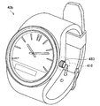
Next, as Example 4, an example of an information processing apparatus configured as a so-called watch-type wearable device that can be worn on an arm will be described with reference to FIGS. 18 and 19.
例えば、図18は、実施例4に係る情報処理装置の一例について説明するための説明図である。なお、本説明では、図18に示す情報処理装置を、前述した実施形態に係る情報処理装置10や、他の実施例に係る情報処理装置と区別するために、「情報処理装置40a」と称する場合がある。
For example, FIG. 18 is an explanatory diagram for explaining an example of the information processing apparatus according to the fourth embodiment. In this description, the information processing apparatus shown in FIG. 18 is referred to as an “
図18に示すように、情報処理装置40aは、集音部411〜415を含む。なお、情報処理装置40aおいては、集音部411〜415が、前述した実施形態に係る情報処理装置10における、集音部110(例えば、図1に示す集音部111〜113等)に相当する。
As illustrated in FIG. 18, the
具体的には、情報処理装置40aは、各種機能を実現するための回路等が組み込まれた筐体481と、当該筐体481をユーザの腕に支持するベルト状の支持部材482とを含む。筐体481は、前述した実施例3に係る情報処理装置30と同様に、少なくとも一部に略矩形状の面を有し、当該略矩形状の面の角を含む所定の領域に、当該筐体481の外側を向くように流線型の形状を有する凸部が形成されている。なお、当該略矩形状の面は、所謂時計における文字盤が設けられる側の面に相当する。そして、集音部411〜414のそれぞれは、当該凸部のうちのいずれかの先端(または、当該先端の近傍)に、筐体481の外側を向くように設けられている。
Specifically, the
また、支持部材482には、情報処理装置40aが腕に装着された状態において、当該腕を基準として、筐体481とは略対称となる位置に集音部415が、当該腕とは逆側の方向を向くように設けられている。
In addition, in the state where the
このような構成により、情報処理装置40aは、例えば、ユーザが、情報処理装置40aが装着された側の腕を振っているような状況下においても、集音部411〜414のうちの少なくともいずれかが、腕が振られる方向と略等しい方向を向いている状態となる。そのため、情報処理装置40aは、集音部411〜414による集音結果により、腕の振りに伴う風切音の影響を緩和することが可能となる。また、情報処理装置40aは、集音部411〜415が互いに異なる方向を向くように設けられている。特に、集音部415については、当該集音部415が向いている方向とは逆側から到来する雑音が、情報処理装置40aが装着された腕により遮蔽される。このような構成により、情報処理装置40aは、集音部411〜415のうち、少なくとも一部の集音部の集音結果に基づき、他の集音部の特性を補うことも可能となる。
With such a configuration, the
また、図19は、実施例4に係る情報処理装置の他の一例について説明するための説明図である。なお、本説明では、図19に示す情報処理装置を、前述した実施形態に係る情報処理装置10や、他の実施例に係る情報処理装置と区別するために、「情報処理装置40b」と称する場合がある。
FIG. 19 is an explanatory diagram for explaining another example of the information processing apparatus according to the fourth embodiment. In this description, the information processing apparatus shown in FIG. 19 is referred to as an “
図19に示すように、情報処理装置40bは、参照符号483で示された所謂時計のネジ部に相当する部分(以降では、「ネジ部483」と称する)に、集音部416を備える。具体的には、ネジ部483を、流線形の形状を有するように形成することで、当該ネジ部483を、集音部416を設けるための凸部として利用してもよい。なお、情報処理装置40bおいては、集音部416が、前述した実施形態に係る情報処理装置10における、集音部110(例えば、集音部111)に相当する。
As illustrated in FIG. 19, the
以上、実施例4として、図18及び図19を参照して、腕に装着され得る、所謂時計型のウェアラブルデバイスとして構成された情報処理装置の一例について説明した。 As described above, as the fourth embodiment, an example of the information processing apparatus configured as a so-called watch-type wearable device that can be worn on the arm has been described with reference to FIGS. 18 and 19.
<1.5.5.実施例5:撮像装置への適用例>
次に、実施例5として、図20及び図21を参照して、動画像や静止画像を撮像可能な撮像装置として構成された情報処理装置の一例について説明する。<1.5.5. Example 5: Application Example to Imaging Device>
Next, as Example 5, an example of an information processing apparatus configured as an imaging apparatus capable of capturing a moving image or a still image will be described with reference to FIGS. 20 and 21. FIG.
例えば、図20は、実施例5に係る情報処理装置の一例について説明するための説明図である。なお、本説明では、図20に示す情報処理装置を、前述した実施形態に係る情報処理装置10や、他の実施例に係る情報処理装置と区別するために、「情報処理装置50」と称する場合がある。
For example, FIG. 20 is an explanatory diagram for explaining an example of the information processing apparatus according to the fifth embodiment. In this description, the information processing apparatus shown in FIG. 20 is referred to as an “
図20において、参照符号53は、動画像や静止画像等の画像を撮像するための撮像部に相当する。また、参照符号511及び512は、情報処理装置50に設けられた集音部の一例に相当する。なお、情報処理装置50おいては、集音部511及び512が、前述した実施形態に係る情報処理装置10における、集音部110(例えば、図1に示す集音部111〜113等)に相当する。
In FIG. 20,
具体的には、図20に示すように、情報処理装置50は、例えば、撮像部53を支持する筐体の、当該撮像部53が画像を撮像する方向(以降では、「撮像方向」と称する場合がある)を向いた面の一部に、当該撮像方向に突出した流線形の形状を有する凸部を備える。そして、当該凸部の先端(または、当該先端の近傍)には、撮像部53の撮像方向(換言すると、前方)を向くように集音部511が設けられている。
Specifically, as illustrated in FIG. 20, the
また、撮像部53の近傍(例えば、撮像部53のレンズの近傍)に、集音部512が設けられていてもよい。例えば、図21は、実施例5に係る情報処理装置50における撮像部53のレンズの近傍の概略的な構成の一例について説明するための説明図である。図21に示す例では、情報処理装置50は、撮像部53のレンズの近傍に、当該情報処理装置50の筐体の外側に向けて突出する凸部551が設けられている。また、凸部551は、撮像部53の撮像方向(即ち、前方)に向けて突出した流線型の形状を有する凸部553を備え、当該凸部553の先端(または、当該先端の近傍)に集音部513が設けられている。
Further, a
このような構成により、情報処理装置50は、例えば、ユーザが移動しながら画像を撮像するような状況下においても、ユーザの移動により前方から到来する風に伴う風切音の影響を緩和することが可能となる。
With such a configuration, the
また、図20及び図21には図示していないが、情報処理装置50は、集音部511及び512とは異なる他の集音部を備えていてもよい。この場合には、当該他の集音部は、集音部511及び512とは異なる方向を向くように設けられているとよい。より具体的な一例として、例えば、情報処理装置50の筐体の、撮像部53の撮像方向とは逆側の面に、当該撮像方向とは逆側の方向(即ち、後方)に向くように当該他の集音部が設けられていてもよい。このような構成とすることで、例えば、他の集音部による集音結果に基づき、集音部511及び512の特性を補うことも可能となる。
Although not shown in FIGS. 20 and 21, the
以上、実施例5として、図20及び図21を参照して、動画像や静止画像を撮像可能な撮像装置として構成された情報処理装置の一例について説明した。 As described above, as Example 5, an example of an information processing apparatus configured as an imaging apparatus capable of capturing a moving image or a still image has been described with reference to FIGS. 20 and 21.
<<2.第2の実施形態>>
<2.1.概要>
続いて、本開示の第2の実施形態について説明する。前述した第1の実施形態に係る情報処理装置10では、複数の集音部それぞれの集音結果に基づき、観測レベル(即ち、集音された音響のレベル)のより小さい集音部の入力が優先されるようにフィルタリング処理を施すことで、風切音のようなランダムに発生する雑音の影響を低減していた。このような制御により、特に、風切音のようなランダムに発生する雑音の影響がより大きい場合に、より好適な態様で当該雑音の影響を緩和することが可能となる。<< 2. Second Embodiment >>
<2.1. Overview>
Subsequently, a second embodiment of the present disclosure will be described. In the
一方で、上述した制御のように各集音部の集音結果をそのまま評価する場合には、音声等の目的音が主な成分として集音されるような状況下において、当該目的音をより高いレベルで集音した集音部の集音結果が使用されない場合がある。即ち、風切音等のランダムに発生する雑音の影響が小さい状況下においては、例えば、SN比(signal-to-noise ratio)の小さい集音部の集音結果が優先的に使用される場合がある。 On the other hand, when the sound collection result of each sound collection unit is evaluated as it is as in the above-described control, the target sound is more accurately obtained in a situation where the target sound such as speech is collected as a main component. The sound collection result of the sound collection unit collected at a high level may not be used. That is, in a situation where the influence of randomly generated noise such as wind noise is small, for example, the sound collection result of the sound collection unit having a small signal-to-noise ratio (SN) is preferentially used. There is.
そこで、本実施形態では、前述した第1の実施形態と同様に風切音等のランダムに発生する雑音の抑圧効果を維持し、さらに、ランダムに発生する雑音の影響が小さい場合において、より好適な態様で目的音を取得することが可能な仕組みの一例について提案する。 Therefore, the present embodiment maintains the effect of suppressing noise generated randomly such as wind noise as in the first embodiment described above, and is more preferable when the influence of randomly generated noise is small. An example of a mechanism that can acquire the target sound in various ways is proposed.
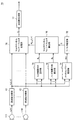
<2.2.機能構成>
まず、図22を参照して、本実施形態に係る情報処理装置の機能構成の一例について説明する。図22は、本実施形態に係る情報処理装置の機能構成の一例を示したブロック図である。なお、以降の説明では、本実施形態に係る情報処理装置を、前述した第1の実施形態に係る情報処理装置10(図6参照)と明示的に区別するために、「情報処理装置60」と称する場合がある。<2.2. Functional configuration>
First, an example of a functional configuration of the information processing apparatus according to the present embodiment will be described with reference to FIG. FIG. 22 is a block diagram illustrating an example of a functional configuration of the information processing apparatus according to the present embodiment. In the following description, in order to explicitly distinguish the information processing apparatus according to the present embodiment from the
図22に示すように、本実施形態に係る情報処理装置60は、複数の集音部111〜11M(Mは正の整数)と、周波数分解部13と、チャネルパワー推定部65と、フィルタ推定部66と、フィルタ処理部17と、周波数合成部18とを含む。なお、複数の集音部111〜11M(Mは正の整数)と、周波数分解部13と、フィルタ処理部17と、周波数合成部18とは、前述した第1の実施形態に係る情報処理装置10(図6参照)において、同様の符号が付された構成に相当する。即ち、本実施形態に係る情報処理装置60は、チャネルパワー推定部65及びフィルタ推定部66の処理内容が、前述した第1の実施形態に係る情報処理装置10と異なる。そこで、以降では、本実施系形態に係る情報処理装置60の機能構成について、特に、前述した第1の実施形態に係る情報処理装置10と異なる部分に着目して説明し、当該情報処理装置10と同様の構成については詳細な説明は省略する。
As illustrated in FIG. 22, the
図22に示すように、チャネルパワー推定部65は、入力パワー推定部651と、非相関成分パワー推定部653と、ランダムノイズパワー推定部655とを含む。
As shown in FIG. 22, channel
入力パワー推定部651は、前述した第1の実施形態に係る情報処理装置10におけるチャネルパワー推定部15に相当する。即ち、入力パワー推定部651は、各集音部110それぞれに対応する音響信号xm(n)の各周波数成分Xm(i,k)に基づき、周波数ごとに、各集音部110のパワースペクトルを推定する。そして、入力パワー推定部651は、周波数ごとに、各集音部110のパワースペクトルPm(i,k)の推定結果を、ランダムノイズパワー推定部655に出力する。The input
非相関成分パワー推定部653は、フィルタ処理部17によりフィルタリング処理が施されることで生成された出力信号Y(i,k)のフィードバックを受ける。なお、当該出力信号Y(i,k)は、従前に集音された集音部110ごとの音響信号xm(n)の各周波数成分Xm(i,k)において雑音(ランダムノイズ)の影響が抑圧された音響であり、例えば、ユーザが発話した音声等のような目的音の、集音部110ごとの周波数成分に相当する。次いで、非相関成分パワー推定部653は、各集音部110それぞれに対応する音響信号xm(n)の各周波数成分Xm(i,k)と、フィードバックされた出力信号Y(i,k)との間の相関性に基づき、当該出力信号Y(i,k)と非相関の成分のパワースペクトルQm(i,k)を推定する。なお、周波数成分Xm(i,k)のうち、出力信号Y(i,k)と非相関の成分(以降では、単に「非相関成分」とも称する)が、当該周波数成分Xm(i,k)に含まれるランダムノイズ等の雑音の成分に相当する。また、非相関成分パワー推定部653による信号処理の詳細については別途後述する。そして、非相関成分パワー推定部653は、周波数ごとに、各集音部110のパワースペクトルQm(i,k)の推定結果をランダムノイズパワー推定部655に出力する。The uncorrelated component
ランダムノイズパワー推定部655は、入力パワー推定部651から、周波数ごとに、各集音部110のパワースペクトルPm(i,k)の推定結果を取得する。また、ランダムノイズパワー推定部655は、非相関成分パワー推定部653から、周波数ごとに、各集音部110に対応する非相関成分のパワースペクトルQm(i,k)の推定結果を取得する。そして、ランダムノイズパワー推定部655は、取得したパワースペクトルPm(i,k)及びQm(i,k)それぞれの推定結果に基づき、フィルタ推定部66がフィルタ係数w(i,k)を算出するための、周波数ごとの、各集音部110のパワースペクトルWm(i,k)を決定する。なお、ランダムノイズパワー推定部655による、パワースペクトルWm(i,k)の決定に係る処理の詳細については別途後述する。そして、ランダムノイズパワー推定部655は、周波数ごとに、各集音部110のパワースペクトルWm(i,k)を示す情報を、フィルタ推定部66に出力する。The random noise
フィルタ推定部66は、チャネルパワー推定部65から出力される、周波数ごとの、各集音部110のパワースペクトルWm(i,k)を示す情報に基づき、フィルタ処理部17が、フィルタリング処理を実行するためのフィルタ係数w(i,k)を算出する。なお、このときフィルタ推定部66は、(式2)として示した前述した行列R(i,k)を生成する際に、パワースペクトルPm(i,k)に替えて、パワースペクトルWm(i,k)を適用する点で、前述した第1の実施形態に係るフィルタ推定部16と異なる。Based on information indicating the power spectrum Wm (i, k) of each sound collection unit 110 for each frequency output from the channel
一方で、以降の処理、即ち、(式3)〜(式6)に基づき前述した、アレイマニフォールドベクトルa(k)と、生成した行列R(i,k)とに基づきフィルタ係数w(i,k)の算出に係る処理については、前述した第1の実施形態に係るフィルタ推定部16と同様である。そのため、当該処理の内容については、詳細な説明は省略する。
On the other hand, filter coefficients w (i, k) based on the array manifold vector a (k) and the generated matrix R (i, k) described above based on the subsequent processing, that is, (Expression 3) to (Expression 6). The processing related to the calculation of k) is the same as that of the filter estimation unit 16 according to the first embodiment described above. Therefore, detailed description of the contents of the processing is omitted.
以上のようにして、フィルタ推定部66は、取得した周波数ごとの、各集音部110のパワースペクトルWm(i,k)を示す情報に基づきフィルタ係数w(i,k)を算出し、算出したフィルタ係数w(i,k)を、フィルタ処理部17に出力する。なお、以降の処理については、前述した第1の実施形態に係る情報処理装置10(図6参照)と同様である。
As described above, the
以上、図22を参照して、本実施形態に係る情報処理装置の機能構成の一例について説明した。 Heretofore, an example of the functional configuration of the information processing apparatus according to the present embodiment has been described with reference to FIG.
<2.3.非相関成分パワー推定部の詳細>
続いて、非相関成分パワー推定部653が、周波数ごとに、各集音部110に対応する非相関成分のパワースペクトルQm(i,k)を算出する処理の詳細について説明する。<2.3. Details of uncorrelated component power estimation unit>
Next, details of processing in which the decorrelation component
まず、非相関成分パワー推定部653が、パワースペクトルQm(i,k)を算出するための基本原理について説明する。マイクロフォン等の集音部に入力される音響(信号)には、例えば、ユーザの音声等のような目的音Smと、所謂背景ノイズNmと、風切音等のようなランダムノイズWmとが含まれる。即ち、集音部110ごとの音響信号xm(n)の各周波数成分Xm(i,k)は、目的音Sm、背景ノイズNm、及びランダムノイズWmに基づき、以下に(式8)として示す関係式で表される。First, the basic principle for the uncorrelated component
ここで、M個の集音部それぞれの入力される音響(信号)をまとめると、以下に(式9)として示す関係式で表される。 Here, the sounds (signals) input to each of the M sound collecting units are summarized and expressed by the relational expression shown as (Equation 9) below.
上記に示した(式9)において、Sは、目的音SmをM個の集音部についてまとめたものである。同様に、Nは、背景ノイズNmをM個の集音部についてまとめたものであり、Wは、ランダムノイズWmをM個の集音部についてまとめたものである。なお、S、N、及びWは、それぞれベクトルとして示される。また、Sorgは、音源から出力された目的音そのものを示しており、スカラー値で示される。また、akは、前述したアレイマニフォールドベクトルa(k)に相当する。即ち、Sは、音源から出力された目的音Sorgが、集音部に到達するまでの空間を伝搬する際に生じる、信号の劣化や遅延等の影響を考慮した目的音の成分を示している。In shown in (Equation 9), S is for the target sound S m summarizes the M sound collecting unit. Similarly, N represents the background noise N m is a summary for M sound collecting unit, W is one in which the random noise W m summarizes the M sound collecting unit. Note that S, N, and W are each shown as a vector. S org indicates the target sound itself output from the sound source, and is represented by a scalar value. Further, a k corresponds to the array manifold vector a (k) described above. In other words, S indicates a component of the target sound that takes into account the effects of signal degradation, delay, and the like that occur when the target sound S org output from the sound source propagates through the space until it reaches the sound collection unit. Yes.
ここで、風切音等のようなランダムノイズWの発生タイミングはランダムであり、本開示に係る情報処理装置では、複数の集音部(特に、図1に示すように分散配置された集音部)間において近似的には相関性の無い信号として定義することが可能である。 Here, the generation timing of random noise W such as wind noise is random, and in the information processing apparatus according to the present disclosure, a plurality of sound collection units (particularly, sound collections arranged in a distributed manner as shown in FIG. 1). Part) can be defined as signals having no correlation.
このような特性に基づき、上記(式9)は、図23に示すようなベクトル間の関係として規定することが可能である。図23は、非相関成分パワー推定部653の処理の基本原理について説明するための説明図である。なお、図23に示す例では、ユーザが発話した音声を目的音として集音する場合について示している。また、図23に示すベクトル空間は、マニフォールドベクトルakに基づき規定される。Based on such characteristics, (Equation 9) can be defined as a relationship between vectors as shown in FIG. FIG. 23 is an explanatory diagram for explaining a basic principle of processing of the uncorrelated component
図23において、Xは、集音部により集音された音響(即ち、入力信号)を示しており、(式9)に示したXに相当する。また、Yは、理想的には、入力信号Xに対する目的音Sorgの推定結果に基づく成分(即ち、ユーザの発話成分)に相当する。即ち、成分Yは、入力信号Xに含まれる各成分のうち、ユーザの発話成分(もしくは、ユーザの発話成分と相関性を有する成分)を模式的に示している。これに対して、Zは、入力信号Xに含まれる各成分のうち、ユーザの発話成分との相関性が小さい(もしくは、相関性の無い)成分に相当する。In FIG. 23, X represents the sound collected by the sound collection unit (that is, the input signal), and corresponds to X shown in (Equation 9). Y ideally corresponds to a component based on the estimation result of the target sound S org with respect to the input signal X (that is, a user's utterance component). That is, the component Y schematically shows a user's speech component (or a component having a correlation with the user's speech component) among the components included in the input signal X. On the other hand, Z corresponds to a component having a small correlation (or no correlation) with the user's speech component among the components included in the input signal X.
なお、背景ノイズNとランダムノイズWとを全て抑圧することが可能であれば、成分Zは、背景ノイズN及びランダムノイズWの成分のみとなる。しかしながら、本開示に係る情報処理装置(例えば、図1参照)のように首回りに各集音部が配置される構成では、集音部間が比較的近傍に位置するため、背景ノイズNは、当該集音部間において相関性を有する成分として観測される。そのため、成分Yには、ユーザの発話成分Sに加えて、背景ノイズNの成分が含まれる。一方で、風切音等のようなランダムノイズWは、ユーザの発話成分との相関性が小さいため、成分Zとして示される。 If it is possible to suppress both the background noise N and the random noise W, the component Z is only the components of the background noise N and the random noise W. However, in the configuration in which the sound collection units are arranged around the neck as in the information processing apparatus according to the present disclosure (see, for example, FIG. 1), the background noise N is , It is observed as a component having a correlation between the sound collecting parts. Therefore, the component Y includes a background noise N component in addition to the user's utterance component S. On the other hand, random noise W such as wind noise is indicated as a component Z because the correlation with the user's speech component is small.
以上のような特性を利用し、非相関成分パワー推定部653は、出力信号Y(即ち、ユーザの発話成分)のフィードバックを利用することで、当該出力信号Yと相関性の小さい(もしくは、相関性の無い)成分を、ランダムノイズWの成分として抽出する。なお、以降の説明では、成分Zを、「非相関成分Z」とも称する。
By utilizing the characteristics as described above, the uncorrelated component
例えば、集音部110の数が4個の場合には、(式4)として前述した計算式に基づき、アレイマニフォールドベクトルakは、以下に(式10)として示す計算式で表される。For example, when the number of the sound collecting units 110 is four, the array manifold vector a k is expressed by the calculation formula shown below as (Formula 10) based on the calculation formula described above as (Formula 4).
ここで、入力信号Xと、マニフォールドベクトルakとの内積に基づき、当該入力信号Xをマニフォールドベクトルakに射影した成分を抽出することが可能である。このような特性から、マニフォールドベクトルakに直交する成分として、非相関成分Zを、以下に(式11)として示す計算式に基づき抽出することが可能である。Here, an input signal X, based on the inner product of the manifold vector a k, it is possible to extract a component obtained by projecting the input signal X to the manifold vectors a k. From such characteristics, it is possible to extract the non-correlated component Z as a component orthogonal to the manifold vector ak based on the calculation formula shown below as (Equation 11).
ここで、上記(式11)において、(ak H・ak)−1・ak H・Xとして示された成分が、図23に示したユーザの発話成分Yに相当する。即ち、上記(式11)は、以下に(式12)として示す計算式で表すことが可能となる。Here, in the above equation (11), (a k H · a k) -1 · a k H · X as indicated component corresponds to the user's utterance component Y shown in FIG. 23. That is, the above (Formula 11) can be expressed by a calculation formula shown as (Formula 12) below.
ここで、上記(式12)における成分Yとして、フィードバックされた出力信号Y(即ち、フィルタ処理部17によるフィルタリング処理後の出力信号)を適用すると、上記(式12)は、前述した(式6)に基づき、以下に(式13)として示す計算式で表すことが可能となる。
Here, when the output signal Y fed back (that is, the output signal after the filtering process by the filter processing unit 17) is applied as the component Y in the above (Expression 12), the above (Expression 12) becomes the above-described (
以上のようにして算出された非相関成分Zに基づき信号のパワーを算出し、時間平滑化を行うことで、非相関成分Zのパワースペクトルを推定することが可能となる。ここで、m番目の集音部110(即ち、集音部11m)における、iフレーム、周波数kに対応する非相関成分ZのパワースペクトルQm(i,k)は、以下に(式14)として示す計算式で表される。なお、以下に示す(式14)において、Zm *(i,k)は、Zm(i,k)の共役複素数を示している。また、(式14)において、rは、急激なパワースペクトルの変化を抑制するためのフレーム方向の平滑化係数を表すものとする(0≦r<1)。It is possible to estimate the power spectrum of the uncorrelated component Z by calculating the signal power based on the uncorrelated component Z calculated as described above and performing time smoothing. Here, the power spectrum Q m (i, k) of the decorrelation component Z corresponding to the i frame and the frequency k in the m-th sound collecting unit 110 (that is, the sound collecting unit 11m) is expressed as (Equation 14) below. It is expressed by the calculation formula shown as In (Expression 14) shown below, Z m * (i, k) represents a conjugate complex number of Z m (i, k). In (Expression 14), r represents a smoothing coefficient in the frame direction for suppressing a rapid change in power spectrum (0 ≦ r <1).
以上のようにして、非相関成分パワー推定部653は、非相関成分のパワースペクトルQm(i,k)を算出する。As described above, the uncorrelated component
なお、非相関成分パワー推定部653は、パワースペクトルQm(i,k)を推定する際に、2以上の集音部110の集音結果を使用できれば、必ずしも全ての集音部110の集音結果を使用する必要はない。具体的な一例として、非相関成分パワー推定部653は、ユーザの頭部に対して後方に位置する集音部110のように、音声等の目的音を集音しにくい位置に設置された集音部110の集音結果については、パワースペクトルQm(i,k)の推定に使用しなくてもよい。Note that the non-correlated component
以上、非相関成分パワー推定部653が、周波数ごとに、各集音部110に対応する非相関成分のパワースペクトルQm(i,k)を算出する処理の詳細について説明した。The details of the process in which the decorrelation component
<2.4.ランダムノイズパワー推定部の詳細>
続いて、ランダムノイズパワー推定部655が、フィルタ係数w(i,k)の算出に用いられる、周波数ごとの、各集音部110のパワースペクトルWm(i,k)を決定する処理の詳細について説明する。<2.4. Details of Random Noise Power Estimator>
Subsequently, details of the process in which the random noise
前述したように、ランダムノイズパワー推定部655は、入力パワー推定部651から取得されるパワースペクトルPm(i,k)と、非相関成分パワー推定部653から取得される非相関成分のパワースペクトルQm(i,k)とのぞれぞれの推定結果に基づき、パワースペクトルWm(i,k)を決定する。As described above, the random noise
(パワースペクトルQmを適用するケース)
例えば、ランダムノイズパワー推定部655は、非相関成分のパワースペクトルQm(i,k)の推定結果を、パワースペクトルWm(i,k)としてフィルタ推定部66に出力してもよい。なお、この場合には、チャネルパワー推定部65は、入力パワー推定部651を含まなくてもよい。(Case of applying the power spectrum Q m)
For example, the random noise
(パワースペクトルPm及びQmを選択的に切り替えるケース)
また、他の一例として、ランダムノイズパワー推定部655は、所定の条件に基づき、パワースペクトルPm(i,k)及びQm(i,k)それぞれの推定結果のうちのいずれかを選択的に、パワースペクトルWm(i,k)としてフィルタ推定部66に出力してもよい。(Case where the power spectra P m and Q m are selectively switched)
As another example, the random noise
(パワースペクトルWmを適応的に算出するケース)
また、他の一例として、ランダムノイズパワー推定部655は、パワースペクトルPm(i,k)及びQm(i,k)それぞれの推定結果に基づき、パワースペクトルWm(i,k)を適応的に算出してもよい。(Case where the power spectrum W m is calculated adaptively)
As another example, the random noise
例えば、ランダムノイズパワー推定部655は、パワースペクトルPm(i,k)及びQm(i,k)を入力として、以下に(式15)として示す計算式に基づき、目的音(音声等)とランダムノイズとの関係を考慮したパワースペクトルWm 〜を算出する。なお、「Wm 〜」は、「Wm」の上にチルダが付された文字を示すものとする。また、以下に示すPm及びQmは、パワースペクトルPm(i,k)及びQm(i,k)を一般化して記載したものである。For example, the random noise
例えば、以下に示す(式16)は、パワースペクトルPm(i,k)及びQm(i,k)を入力として、目的音とランダムノイズとの関係を考慮したパワースペクトルWm 〜を算出するための関数Fの具体的な一例を示している。For example, (Equation 16) shown below calculates the power spectrum W m ˜ taking into account the relationship between the target sound and random noise, with the power spectra P m (i, k) and Q m (i, k) as inputs. A specific example of the function F for doing this is shown.
そして、ランダムノイズパワー推定部655は、上述した目的音とランダムノイズとの関係を考慮したパワースペクトルWm 〜に基づき、パワースペクトルWmを、以下に(式17)として示す計算式に基づき算出する。なお、(式17)において、rは、急激なパワースペクトルの変化を抑制するためのフレーム方向の平滑化係数を表している(0≦r<1)。即ち、ランダムノイズパワー推定部655は、以下に(式17)として示す計算式に基づき算出されるパワースペクトルWmを、係数rの設定に基づきフレーム間で平滑化してもよい。Then, random noise
ここで、(式16)に示すパワースペクトルPm、即ち、入力パワー推定部651によるパワースペクトルPm(i,k)の推定結果は、前述したように、集音部110により集音された音響のレベルに相当する。これに対して、(式16)に示すパワースペクトルQm、即ち、非相関成分パワー推定部653によるパワースペクトルQm(i,k)の推定結果は、風切音等のようなランダムノイズのレベルに相当する。即ち、(式16)に示した重みQm/(Pm+Qm)は、音声等の目的音と、風切音等のランダムノイズとの間の関係に基づき変化する。Here, the power spectrum P m shown in (Equation 16), that is, the estimation result of the power spectrum P m (i, k) by the input
具体的には、ランダムノイズに対して目的音の信号レベルが十分に大きい場合には、パワースペクトルPmの影響が支配的となり、重みQm/(Pm+Qm)はより小さくなる。即ち、この場合における当該重みQm/(Pm+Qm)は、対応するチャネル(即ち、集音部110)の集音結果の使用をより抑制する制御を示している。ここで、フィルタ係数w(i,k)の算出には、上記重みQm/(Pm+Qm)の逆数が適用される。そのため、ランダムノイズに対して目的音の信号レベルが十分に大きい場合には、該当するチャネルによる集音結果の使用がより優先されるように、フィルタ係数w(i,k)が算出されることとなる。Specifically, when the signal level of the target sound is sufficiently large with respect to random noise, the influence of the power spectrum P m becomes dominant, and the weight Q m / (P m + Q m ) becomes smaller. That is, the weight Q m / (P m + Q m ) in this case indicates control that further suppresses use of the sound collection result of the corresponding channel (that is, the sound collection unit 110). Here, the reciprocal of the weight Q m / (P m + Q m ) is applied to the calculation of the filter coefficient w (i, k). Therefore, when the signal level of the target sound is sufficiently high with respect to random noise, the filter coefficient w (i, k) is calculated so that the use of the sound collection result by the corresponding channel is given higher priority. It becomes.
一方で、風切音等のようなランダムノイズの影響がより大きい場合には、パワースペクトルQmの影響がより支配的となり、重みQm/(Pm+Qm)はより大きくなる。即ち、この場合における当該重みQm/(Pm+Qm)は、対応するチャネル(即ち、集音部110)の集音結果の使用をより優先する制御を示している。なお、前述したようにフィルタ係数w(i,k)の算出には、上記重みQm/(Pm+Qm)の逆数が適用される。そのため、ランダムノイズの影響がより大きい場合には、該当するチャネルによる集音結果の使用が抑制されるように、フィルタ係数w(i,k)が算出されることとなる。On the other hand, is greater than the effect of random noise such as wind noise, the influence of the power spectrum Q m becomes more dominant, weight Q m / (P m + Q m) is greater. That is, the weight Q m / (P m + Q m ) in this case indicates control that gives priority to the use of the sound collection result of the corresponding channel (that is, the sound collection unit 110). As described above, the reciprocal of the weight Q m / (P m + Q m ) is applied to the calculation of the filter coefficient w (i, k). Therefore, when the influence of random noise is greater, the filter coefficient w (i, k) is calculated so that the use of the sound collection result by the corresponding channel is suppressed.
即ち、上述した制御により、風切音等のランダムノイズの影響が小さく、主に音声が集音されるような状況下では、音声のレベルがより高く集音された集音部110の集音結果が、より優先的に使用されて、フィルタ係数w(i,k)が算出される。これに対して、風切音等のランダムノイズの影響が大きい状況下では、前述した第1の実施形態と同様に、観測レベルのより小さい集音部110の集音結果が、より優先的に使用されて、フィルタ係数w(i,k)が算出されることとなる。このように、ランダムノイズパワー推定部655は、フィルタ係数w(i,k)が算出するためのパワースペクトルWm(i,k)を、音声等のような目的音と、風切音等のようなランダムノイズとの関係に応じて、適応的に算出することが可能となる。
In other words, under the circumstances where random noise such as wind noise is small and the sound is mainly collected by the control described above, the sound collecting unit 110 that has collected the sound at a higher sound level. The result is used more preferentially to calculate the filter coefficient w (i, k). On the other hand, under the situation where the influence of random noise such as wind noise is large, the sound collection result of the sound collection unit 110 having a smaller observation level is more preferentially the same as in the first embodiment described above. Used to calculate the filter coefficient w (i, k). As described above, the random noise
そして、ランダムノイズパワー推定部655は、上記(式17)に基づき算出したパワースペクトルWm(i,k)を、フィルタ推定部66に出力してもよい。
Then, the random noise
以上、ランダムノイズパワー推定部655が、フィルタ係数w(i,k)の算出に用いられる、周波数ごとの、各集音部110のパワースペクトルWm(i,k)を決定する処理の詳細について説明した。なお、上記に説明した例は、あくまで一例であり、パワースペクトルPm(i,k)及びQm(i,k)の少なくともいずれかの推定結果に基づき、パワースペクトルWm(i,k)を決定することが可能であれば、その内容は特に限定されない。The details of the process in which the random noise
<2.5.評価>
以上説明したように、本実施形態に係る情報処理装置60は、複数の集音部110のうち少なくとも2以上の集音部110による集音結果と、フィルタ処理部17の出力信号Y(i,k)のフィードバックとに基づき、非相関成分のパワースペクトルQm(i,k)を推定する。そして、情報処理装置60は、非相関成分のパワースペクトルQm(i,k)の推定結果を、フィルタ係数w(i,k)の推定に利用する。このような構成により、情報処理装置60は、前述した第1の実施形態と同様に風切音等のランダムに発生する雑音の抑圧効果を維持し、さらに、ランダムに発生する雑音の影響が小さい場合において、より好適な態様で目的音を取得することが可能となる。<2.5. Evaluation>
As described above, the
なお、上記では、本実施形態に係る信号処理を、例えば、図1に示した所謂ネックバンド型のウェアラブルデバイスに適用する場合に着目して説明した。一方で、本実施形態に係る信号処理の適用先は、必ずしも図1に示す例のみには限定されない。具体的には、本実施系に係る信号処理は、複数の集音部を備える装置であれば適用することが可能である。なお、より好適には、複数の集音部は、目的音の音源(例えば、音声が発話される口元)からの距離が互いに異なるように配置されているとよい。また、より好適には、複数の集音部は、目的音の音源に対して互いに異なる方向に位置するように配置されているとよい。 In the above description, the signal processing according to the present embodiment has been described focusing on the case where it is applied to the so-called neckband type wearable device shown in FIG. On the other hand, the application destination of the signal processing according to the present embodiment is not necessarily limited to the example shown in FIG. Specifically, the signal processing according to the present embodiment can be applied to any device that includes a plurality of sound collection units. More preferably, the plurality of sound collection units may be arranged so that the distances from the sound source of the target sound (for example, the mouth where the voice is spoken) are different from each other. More preferably, the plurality of sound collecting units may be arranged so as to be positioned in different directions with respect to the sound source of the target sound.
<<第3の実施形態>>
<3.1.概要>
続いて、本開示の第3の実施形態として、本開示に係る技術を、所謂マルチチャネルウィナーフィルタ(MWF:Multi Channel Wiener Filter)に適用した場合の一例について説明する。<< Third Embodiment >>
<3.1. Overview>
Subsequently, as a third embodiment of the present disclosure, an example in which the technique according to the present disclosure is applied to a so-called multi-channel Wiener filter (MWF) will be described.
まず、本実施形態に係る情報処理装置の特徴をよりわかりやすくするために、マルチチャネルウィナーフィルタについて概要を説明する。マルチチャネルウィナーフィルタは、背景ノイズの抑圧等に利用される技術である。例えば、マルチチャネルウィナーフィルタをWmwfとした場合に、Wmwfは、以下に(式18)として示す計算式に基づき算出される。First, in order to make the characteristics of the information processing apparatus according to the present embodiment easier to understand, an outline of a multi-channel winner filter will be described. The multi-channel Wiener filter is a technique used for background noise suppression or the like. For example, when the multi-channel winner filter is W mwf , W mwf is calculated based on the calculation formula shown as (Equation 18) below.
上記(式18)において、Sは、音声等のような目的音を示しており、前述した(式9)に示したSorgに相当する。また、Xは、集音部により集音された音響(即ち、入力信号)を示しており、前述した(式9)に示したXに相当する。また、Wは、マルチチャネルウィナーフィルタにおいて、入力信号Xに対して適用されるフィルタを模式的に示したものである。即ち、マルチチャネルウィナーフィルタは、理想的には上記(式18)に示したコスト関数を最小化するフィルタに基づいて元となる信号を復元する。In the above (Expression 18), S indicates a target sound such as voice, and corresponds to S org shown in (Expression 9) described above. X represents the sound collected by the sound collection unit (that is, the input signal), and corresponds to X shown in (Equation 9) described above. W schematically shows a filter applied to the input signal X in the multi-channel Wiener filter. In other words, the multi-channel Wiener filter ideally restores the original signal based on the filter that minimizes the cost function shown in (Equation 18) above.
しかしながら、一般的には、目的音Sを独立して観測することは困難であるため、複数のチャネル(即ち、集音部)のうち一部のチャネルをリファレンスとして、信号劣化と、ノイズの抑圧量と、をトレードオフとした最小化問題に置き換える。この場合には、例えば、マルチチャネルウィナーフィルタWmwfは、以下に(式19)として示す計算式で表される。However, since it is generally difficult to observe the target sound S independently, signal degradation and noise suppression are performed using a part of a plurality of channels (that is, the sound collection unit) as a reference. It replaces it with the minimization problem that trades off quantity. In this case, for example, the multi-channel Wiener filter W mwf is expressed by a calculation formula shown as (Equation 19) below.
上記(式19)において、Xiは、リファレンスとしたチャネルによる集音結果に基づく出力信号を示している。なお、以降の説明においては、リファレンスとしたチャネルを「リファレンスマイク」とも称する。また、Nは、背景ノイズを示しており、前述した(式9)に示したNに相当する。また、係数μは、目的音に対するノイズの抑圧量に応じて設定される係数(重み)であり、例えば、事前の実験等の結果に基づきあらかじめ設定される。また、上記(式19)におけるRx及びRnは、以下に(式20)及び(式21)として示す計算式で表される。また、(式19)において、リファレンスマイクはeiにより特定される。eiは、i番目の値のみが1をとり他の値は0を示すM次ベクトルであり、例えば、以下に示す(式22)のように表される。In the above (Formula 19), X i represents an output signal based on the sound collection result by the channel used as a reference. In the following description, the reference channel is also referred to as a “reference microphone”. N represents background noise, and corresponds to N shown in the above (Equation 9). The coefficient μ is a coefficient (weight) set according to the amount of noise suppression for the target sound, and is set in advance based on, for example, a result of a prior experiment or the like. Further, R x and R n in the above (Formula 19) are represented by the following calculation formulas as (Formula 20) and (Formula 21). Further, in Equation (19), the reference microphone is specified by e i. e i is an M-order vector in which only the i-th value is 1 and the other values are 0, and is expressed as (Equation 22) shown below, for example.
・・・(式22)
... (Formula 22)
なお、上記(式20)において、Xは、複数のチャネルそれぞれによる集音結果に基づく入力信号をベクトルで表したものである。即ち、Rxは、入力信号Xそのものから算出される。また、(式21)において、Nは、目的音が集音されていない区間(以下、「休止区間」とも称する)における、複数のチャネルそれぞれによる集音結果に基づく入力信号(即ち、雑音に相当する信号)をベクトルで表したものである。そのため、Rnは、例えば、目的音が集音される区間(以下、「目的音区間」とも称する)の検出結果に基づき特定される休止区間において算出される。なお、以降では、Rxを「入力相関行列」とも称し、Rnを「ノイズ相関行列」とも称する。In the above (Equation 20), X represents an input signal based on the sound collection results from each of a plurality of channels as a vector. That is, R x is calculated from the input signal X itself. Further, in (Expression 21), N is an input signal based on the sound collection results of each of a plurality of channels in a section where the target sound is not collected (hereinafter also referred to as “pause section”) (ie, equivalent to noise). Signal) is represented by a vector. Therefore, R n is calculated, for example, in a pause period that is specified based on a detection result of a section in which the target sound is collected (hereinafter also referred to as “target sound section”). Hereinafter, R x is also referred to as “input correlation matrix”, and R n is also referred to as “noise correlation matrix”.
ここで、他の実施形態において前述したように、屋外で使用される場合等のような周囲の環境が動的に変化する状況下では、風切音、振動に伴う雑音、及び装置の装着に伴う衣擦れ等のようなランダムノイズが集音部により集音される場合がある。その一方で、従来のマルチチャネルウィナーフィルタにおいては、(式19)においてeiにより固定的に決定される集音部(即ち、リファレンスマイク)に上記ランダムノイズが混入した場合には、当該ランダムノイズを抑制することが困難である。Here, as described above in other embodiments, in situations where the surrounding environment dynamically changes, such as when used outdoors, wind noise, vibration noise, and device mounting. Random noise such as clothing rubbing may be collected by the sound collection unit. On the other hand, in the conventional multi-channel Wiener filter, in the case where the random noise is mixed into e i by sound collecting unit which is determined fixedly in (Equation 19) (i.e., reference microphone) is the random noise Is difficult to suppress.
そこで、本実施形態では、他の実施形態において上述した技術をマルチチャネルウィナーフィルタに対して適用することで、当該マルチチャネルウィナーフィルタにおけるランダムノイズの影響をより低減する仕組みの一例について提案する。 Therefore, this embodiment proposes an example of a mechanism that further reduces the influence of random noise in the multichannel Wiener filter by applying the technique described above in other embodiments to the multichannel Wiener filter.
具体的には、本実施形態に係る情報処理装置では、前述したパワースペクトルPm(または、パワースペクトルWm)の推定結果に基づきランダムノイズの影響がより小さい集音部をリファレンスマイクとして適応的に選択することで、ランダムノイズの影響をより低減する。例えば、以下に(式23)として示す計算式は、本実施形態に係る情報処理装置におけるマルチチャネルウィナーフィルタWmwfの導出に係る基本原理を示している。Specifically, in the information processing apparatus according to the present embodiment, a sound collection unit that is less influenced by random noise is adaptively selected as a reference microphone based on the estimation result of the power spectrum Pm (or power spectrum Wm) described above. By doing so, the influence of random noise is further reduced. For example, the calculation formula shown below as (Formula 23) shows the basic principle relating to the derivation of the multi-channel Wiener filter W mwf in the information processing apparatus according to the present embodiment.
上記(式23)を前述した(式19)と比較するとわかるように、本実施形態に係る情報処理装置では、リファレンスマイクによる集音結果に基づく出力信号Xiとして、他の実施形態において前述したパワースペクトルPm(または、パワースペクトルWm)の推定結果に基づく出力信号Yを適用する。このような構成に基づき、本実施形態に係る情報処理装置は、ランダムノイズの影響がより顕著に表れる状況下(即ち、周囲の環境が動的に変化するような状況下)においても、ランダムノイズの影響のより小さい集音部をリファレンスマイクとして動的に選択する。これにより、本実施形態に係る情報処理装置に依れば、従来のマルチチャネルウィナーフィルタを適用した装置に比べて、ランダムノイズの影響をより低減し、ひいては、より好適な態様で目的音を抽出することが可能となる。なお、以降では、本実施形態に係る情報処理装置についてさらに詳しく説明する。As can be seen by comparing the above (Equation 23) with the above (Equation 19), in the information processing apparatus according to the present embodiment, the output signal X i based on the sound collection result by the reference microphone is described in the other embodiments. The output signal Y based on the estimation result of the power spectrum Pm (or power spectrum Wm) is applied. Based on such a configuration, the information processing apparatus according to the present embodiment can generate random noise even in a situation where the influence of random noise appears more significantly (that is, in a situation where the surrounding environment changes dynamically). The sound collecting part having a smaller influence is dynamically selected as a reference microphone. Thereby, according to the information processing apparatus according to the present embodiment, the influence of random noise is further reduced as compared with a conventional apparatus to which a multi-channel Wiener filter is applied, and thus the target sound is extracted in a more preferable manner. It becomes possible to do. Hereinafter, the information processing apparatus according to the present embodiment will be described in more detail.
<3.2.機能構成>
図24を参照して、本実施形態に係る情報処理装置の機能構成の一例について説明する。図24は、本実施形態に係る情報処理装置の機能構成の一例を示したブロック図である。なお、以降の説明では、本実施形態に係る情報処理装置を、前述した他の実施形態に係る情報処理装置(例えば、情報処理装置10及び60)と明示的に区別するために、「情報処理装置70」と称する場合がある。<3.2. Functional configuration>
With reference to FIG. 24, an example of a functional configuration of the information processing apparatus according to the present embodiment will be described. FIG. 24 is a block diagram illustrating an example of a functional configuration of the information processing apparatus according to the present embodiment. In the following description, in order to explicitly distinguish the information processing apparatus according to the present embodiment from the information processing apparatuses according to the other embodiments described above (for example, the
図24に示すように、本実施形態に係る情報処理装置70は、複数の集音部111〜11M(Mは正の整数)と、周波数分解部13と、チャネルパワー推定部71と、フィルタ推定部72と、入力相関行列算出部73と、ノイズ相関行列算出部74と、マルチチャネルウィナーフィルタ算出部75と、マルチチャネルウィナーフィルタ処理部76と、周波数合成部77と、を含む。なお、複数の集音部111〜11M(Mは正の整数)と、周波数分解部13とは、前述した第1の実施形態に係る情報処理装置10(図6参照)において、同様の符号が付された構成に相当する。即ち、本実施形態に係る情報処理装置70は、チャネルパワー推定部71と、フィルタ推定部72と、入力相関行列算出部73と、ノイズ相関行列算出部74と、マルチチャネルウィナーフィルタ算出部75と、マルチチャネルウィナーフィルタ処理部76と、周波数合成部77との処理内容が、前述した第1の実施形態に係る情報処理装置10と異なる。そこで、以降では、本実施系形態に係る情報処理装置70の機能構成について、特に、前述した第1の実施形態に係る情報処理装置10と異なる部分に着目して説明し、当該情報処理装置10と同様の構成については詳細な説明は省略する。
As shown in FIG. 24, the
(マルチチャネルウィナーフィルタ処理部76)
マルチチャネルウィナーフィルタ処理部76は、周波数分解部13から集音部110ごとに音響信号xm(n)の各周波数成分Xm(i,k)を取得する。また、マルチチャネルウィナーフィルタ処理部76は、後述するマルチチャネルウィナーフィルタ算出部75から、周波数ごとにマルチチャネルウィナーフィルタWmwf(i,k)の算出結果を取得する。なお、マルチチャネルウィナーフィルタWmwf(i,k)の算出方法については詳細を別途後述する。そして、マルチチャネルウィナーフィルタ処理部76は、集音部110ごとの音響信号xm(n)の各周波数成分Xm(i,k)を入力信号として、当該マルチチャネルウィナーフィルタWmwf(i,k)に基づくフィルタリング処理を施すことで、出力信号Sを周波数ごとに生成する。例えば、出力信号Sは、以下に(式24)として示す計算式で表される。なお、以下に示す(式24)では、フレーム番号i及び離散周波数番号kの記載を省略している。(Multi-channel winner filter processing unit 76)
The multi-channel Wiener
そして、マルチチャネルウィナーフィルタ処理部76は、周波数ごとに生成した出力信号Sを、周波数合成部77に出力する。
Then, the multi-channel Wiener
(周波数合成部77)
周波数合成部77は、マルチチャネルウィナーフィルタ処理部76から周波数ごとに生成された出力信号Sを取得する。周波数合成部77は、取得した周波数ごとの出力信号Sを合成することで音響信号を生成する。なお、周波数合成部77による処理は、前述した第1及び第2の実施形態に係る周波数合成部18が、周波数ごとの出力信号Y(i,k)を合成することで音響信号y(n)を生成する処理と同様のため、詳細な説明は省略する。(Frequency synthesizer 77)
The
(チャネルパワー推定部71及びフィルタ推定部72)
続いて、チャネルパワー推定部71及びフィルタ推定部72の構成について説明する。チャネルパワー推定部71及びフィルタ推定部72は、前述した第1の実施形態に係る情報処理装置10と同様の仕組みを適用して構成してもよいし、第2の実施形態に係る情報処理装置60と同様の仕組みを適用して構成してもよい。そこで、以下にそれぞれの場合に着目して説明する。(Channel
Next, the configuration of the channel
(チャネルパワー推定部71及びフィルタ推定部72の構成例1)
まず、前述した第1の実施形態に係る情報処理装置10(図6参照)と同様の仕組みを適用して、チャネルパワー推定部71及びフィルタ推定部72を構成する場合について説明する。この場合には、チャネルパワー推定部71及びフィルタ推定部72は、第1の実施形態に係るチャネルパワー推定部15及びフィルタ推定部16に相当することとなる。(Configuration example 1 of channel
First, a case where the channel
具体的には、チャネルパワー推定部71は、各集音部110それぞれに対応する音響信号xm(n)の各周波数成分Xm(i,k)に基づき、周波数ごとに、各集音部110のパワースペクトルPm(i,k)を推定する。Specifically, the
また、フィルタ推定部72は、パワースペクトルPm(i,k)の推定結果に基づき、フィルタ係数w(i,k)を算出する。そして、フィルタ推定部72は、フィルタ係数w(i,k)の算出結果に基づきフィルタGを周波数ごとに算出し、当該フィルタGの算出結果を後述するマルチチャネルウィナーフィルタ算出部75に出力する。The filter estimation unit 72 calculates a filter coefficient w (i, k) based on the estimation result of the power spectrum P m (i, k). Then, the filter estimation unit 72 calculates the filter G for each frequency based on the calculation result of the filter coefficient w (i, k), and outputs the calculation result of the filter G to the multichannel Wiener
(チャネルパワー推定部71及びフィルタ推定部72の構成例2)
続いて、前述した第2の実施形態に係る情報処理装置60(図22参照)と同様の仕組みを適用して、チャネルパワー推定部71及びフィルタ推定部72を構成する場合について説明する。この場合には、チャネルパワー推定部71及びフィルタ推定部72は、第2の実施形態に係るチャネルパワー推定部65及びフィルタ推定部66に相当することとなる。(Configuration example 2 of channel
Subsequently, a case where the channel
具体的には、チャネルパワー推定部71は、各集音部110それぞれに対応する音響信号xm(n)の各周波数成分Xm(i,k)に基づき、周波数ごとに、各集音部110のパワースペクトルPm(i,k)を推定する。Specifically, the
また、チャネルパワー推定部71は、フィルタリング処理に基づき雑音(特に、ランダムノイズ)の影響が抑圧された周波数ごとの音響信号のフィードバックを受ける。
In addition, the channel
具体的な一例として、フィルタ推定部72は、マルチチャネルウィナーフィルタ処理部76によるフィルタリング処理の結果として出力される周波数ごとの音響信号Sのフィードバックを受けてもよい。
As a specific example, the filter estimation unit 72 may receive feedback of the acoustic signal S for each frequency output as a result of the filtering process by the multichannel Wiener
また、他の一例として、第2の実施形態に係る情報処理装置60におけるフィルタ処理部17に相当する構成を別途設けることで、フィルタ推定部72は、当該構成からノイズ成分が抑圧された周波数ごとの音響信号のフィードバックを受けてもよい。この場合には、フィルタ推定部72は、第2の実施形態に係る情報処理装置60における出力信号Y(i,k)に相当する音響信号のフィードバックを受けることとなる。
As another example, by separately providing a configuration corresponding to the
上記フィードバックを受けると、チャネルパワー推定部71は、各集音部110それぞれに対応する音響信号xm(n)の各周波数成分Xm(i,k)と、フィードバックされた音響信号との間の相関性に基づき、当該音響信号と非相関の成分のパワースペクトルQm(i,k)を推定する。Upon receiving the feedback, the channel
そして、チャネルパワー推定部71は、パワースペクトルPm(i,k)及びQm(i,k)それぞれの推定結果に基づき、フィルタ推定部72がフィルタ係数w(i,k)を算出するための、周波数ごとの、各集音部110のパワースペクトルWm(i,k)を決定すればよい。なお、パワースペクトルPm(i,k)及びQm(i,k)それぞれの算出方法や、パワースペクトルWm(i,k)の決定方法については、前述した第2の実施形態に係るチャネルパワー推定部65と同様のため詳細な説明は省略する。The channel
また、フィルタ推定部72は、パワースペクトルWm(i,k)の推定結果に基づき、フィルタ係数w(i,k)を算出する。そして、フィルタ推定部72は、フィルタ係数w(i,k)の算出結果に基づきフィルタGを周波数ごとに算出し、当該フィルタGの算出結果を後述するマルチチャネルウィナーフィルタ算出部75に出力すればよい。Further, the filter estimation unit 72 calculates the filter coefficient w (i, k) based on the estimation result of the power spectrum W m (i, k). And the filter estimation part 72 will calculate the filter G for every frequency based on the calculation result of filter coefficient w (i, k), and will output the calculation result of the said filter G to the multichannel Wiener
なお、上述した通り、フィルタGは、フィルタ係数w(i,k)に基づき算出されるため、前述した(式2)〜(式6)を鑑みると、例えば、以下に(式25)及び(式26)として示す計算式で表すことが可能である。 Note that, as described above, the filter G is calculated based on the filter coefficient w (i, k). Therefore, in view of the above-described (Expression 2) to (Expression 6), for example, (Expression 25) and ( It can be expressed by a calculation formula shown as Formula 26).
なお、上記(式25)及び(式26)において、Rwは、前述した(式6)における行列R(i,k)に相当する。即ち、第1の実施形態と同様の思想に基づく場合には、Rwは、パワースペクトルPm(i,k)の推定結果に基づく行列となる。また、第1の実施形態と同様の思想に基づく場合には、パワースペクトルPm(i,k)及びQm(i,k)それぞれの推定結果に応じて決定されたパワースペクトルWm(i,k)に基づく行列となる。In the above (Expression 25) and (Expression 26), R w corresponds to the matrix R (i, k) in (Expression 6) described above. That is, when based on the same idea as in the first embodiment, R w is a matrix based on the estimation result of the power spectrum P m (i, k). Further, in the case of being based on the same idea as in the first embodiment, the power spectrum Wm (i, k) determined according to the estimation results of the power spectra P m (i, k) and Q m (i, k). a matrix based on k).
次いで、入力相関行列算出部73、ノイズ相関行列算出部74、及びマルチチャネルウィナーフィルタ算出部75について説明する。
Next, the input correlation
(入力相関行列算出部73)
入力相関行列算出部73は、周波数分解部13から集音部110ごとに音響信号xm(n)の各周波数成分Xm(i,k)を取得する。次いで、入力相関行列算出部73は、取得した各周波数成分Xm(i,k)を入力として、前述した(式20)に基づき、入力相関行列Rxを周波数ごとに算出する。そして、入力相関行列算出部73は、周波数ごとに算出した入力相関行列Rxをマルチチャネルウィナーフィルタ算出部75に出力する。(Input correlation matrix calculation unit 73)
The input correlation
(ノイズ相関行列算出部74)
ノイズ相関行列算出部74は、周波数分解部13から集音部110ごとに音響信号xm(n)の各周波数成分Xm(i,k)を取得する。次いで、ノイズ相関行列算出部74は、音響信号xm(n)の各周波数成分Xm(i,k)の取得結果に基づき休止区間を特定する。次いで、ノイズ相関行列算出部74は、特定した休止区間における当該各周波数成分Xm(i,k)を入力として、前述した(式21)に基づき、ノイズ相関行列Rnを周波数ごとに算出する。そして、ノイズ相関行列算出部74は、周波数ごとに算出したノイズ相関行列Rnをマルチチャネルウィナーフィルタ算出部75に出力する。(Noise correlation matrix calculation unit 74)
The noise correlation
(マルチチャネルウィナーフィルタ算出部75)
マルチチャネルウィナーフィルタ算出部75は、フィルタ推定部72から、フィルタ係数w(i,k)に基づくフィルタGの算出結果を周波数ごとに取得する。また、マルチチャネルウィナーフィルタ算出部75は、入力相関行列算出部73から、入力相関行列Rxの算出結果を周波数ごとに取得する。また、マルチチャネルウィナーフィルタ算出部75は、ノイズ相関行列算出部74から、ノイズ相関行列Rnの算出結果を周波数ごとに取得する。次いで、マルチチャネルウィナーフィルタ算出部75は、周波数ごとに取得した、フィルタG、入力相関行列Rx、及びノイズ相関行列Rnそれぞれの算出結果に基づき、周波数ごとにマルチチャネルウィナーフィルタWmwf(i,k)を算出する。そして、マルチチャネルウィナーフィルタ算出部75は、マルチチャネルウィナーフィルタWmwf(i,k)の算出結果をマルチチャネルウィナーフィルタ処理部76に出力する。これにより、マルチチャネルウィナーフィルタ処理部76は、集音部110ごとの音響信号xm(n)の各周波数成分Xm(i,k)に対して、当該マルチチャネルウィナーフィルタWmwf(i,k)に基づきフィルタリング処理を施すことが可能となる。なお、マルチチャネルウィナーフィルタWmwf(i,k)の算出方法については、より詳細な内容について別途後述する。(Multi-channel winner filter calculation unit 75)
The multi-channel winner
以上、図24を参照して、本実施形態に係る情報処理装置の機能構成の一例について説明した。なお、上述した情報処理装置70の各構成のうち、例えば、マルチチャネルウィナーフィルタ算出部75及びマルチチャネルウィナーフィルタ処理部76が、「出力制御部」の一例に相当する。
The example of the functional configuration of the information processing apparatus according to the present embodiment has been described above with reference to FIG. Of each configuration of the
<3.3.マルチチャネルウィナーフィルタの算出方法の詳細>
続いて、マルチチャネルウィナーフィルタWmwf(i,k)の算出方法についてより詳しく説明する。なお、本説明では、フレーム番号i及び離散周波数番号kの記載については省略するものとする。<3.3. Details of multi-channel winner filter calculation method>
Next, the calculation method of the multi-channel winner filter W mwf (i, k) will be described in more detail. In this description, description of the frame number i and the discrete frequency number k is omitted.
まず、前述した(式23)に着目する。前述したように、フィルタGは、フィルタ係数w(i,k)に基づき算出される。そのため、(式23)に示す出力信号Yは、前述した(式7)を鑑みると、フィルタ係数w(i,k)に基づくフィルタGと、入力信号Xと、により、以下に(式27)として示す計算式で表すことが可能である。 First, pay attention to (Equation 23) described above. As described above, the filter G is calculated based on the filter coefficient w (i, k). For this reason, the output signal Y shown in (Equation 23) takes into account the following (Equation 27) by the filter G based on the filter coefficient w (i, k) and the input signal X in view of the aforementioned (Equation 7). It is possible to express with the calculation formula shown as.
即ち、前述した(式23)は、上記(式27)で示された出力信号Yと、フィルタG、入力相関行列Rx、及びノイズ相関行列Rnと、により、以下に(式28)として示す計算式で表すことが可能である。That is, (Equation 23) described above is expressed as (Equation 28) below using the output signal Y shown in (Equation 27), the filter G, the input correlation matrix R x , and the noise correlation matrix R n. It can be expressed by the calculation formula shown.
ここで、上記(式28)と前述した(式19)とを比較するとわかるように、上記(式28)は、前述した(式19)において、リファレンスマイクを特定する行列eiを、フィルタGに置き換えた計算式と等価であることがわかる。また、フィルタGは、前述した(式25)及び(式26)を鑑みると、以下に(式29)として示す計算式で表すことも可能である。Here, as can be seen by comparing the above (Equation 28) with the above (Equation 19), the above (Equation 28) is obtained by replacing the matrix e i specifying the reference microphone with the filter G in the above (Equation 19). It turns out that it is equivalent to the calculation formula replaced with. The filter G can also be expressed by a calculation formula shown below as (Formula 29) in view of the above-described (Formula 25) and (Formula 26).
ここで、上記(式29)において、係数g1、…、gi、…、gMは、(式25)及び(式26)における行列Rwに基づき決定される係数である。より具体的には、係数g1、…、gi、…、gMは、例えば、前述した第1の実施形態におけるパワースペクトルPm(i,k)の推定結果や、第2の実施形態におけるパワースペクトルWm(i,k)の推定結果に基づき決定されることとなる。即ち、係数g1、…、gi、…、gMは、各集音部110それぞれに対するランダムノイズの影響の大きさに応じた重みを示しており、換言すると、各集音部110それぞれの集音結果が、目的音の集音結果としてのどの程度信頼できるかを示している。Here, in the above (Expression 29), the coefficients g 1 ,..., G i ,..., G M are coefficients determined based on the matrix R w in (Expression 25) and (Expression 26). More specifically, the coefficients g 1 ,..., G i ,..., G M are, for example, the estimation result of the power spectrum P m (i, k) in the first embodiment described above or the second embodiment. Is determined based on the estimation result of the power spectrum Wm (i, k) at. That is, the coefficients g 1 ,..., G i ,..., G M indicate weights according to the magnitude of the influence of random noise on each sound collecting unit 110, in other words, each sound collecting unit 110. The sound collection result indicates how reliable the sound collection result of the target sound is.
即ち、本実施形態に係る情報処理装置70においては、各集音部110による音響(特に、ランダムノイズ)の集音結果に応じて、係数g1、…、gi、…、gMが変化し、当該係数に応じて、例えば、ランダムノイズの影響がより小さい集音部110がリファレンスマイクとして動的に選択されることとなる。That is, in the
<3.4.評価>
以上説明したように、本実施形態に係る情報処理装置70は、各集音部110それぞれに対応する音響信号xm(n)の各周波数成分Xm(i,k)に基づき、周波数ごとに、各集音部110のパワースペクトル(例えば、前述したパワースペクトルPm(i,k)やパワースペクトルWm(i,k))を推定する。そして、情報処理装置70は、当該パワースペクトルの推定結果に基づきフィルタ係数w(i,k)を推定し、当該フィルタ係数w(i,k)の推定結果をマルチチャネルウィナーフィルタWmwf(i,k)の算出に利用する。このような構成により、本実施形態に係る情報処理装置70は、複数の集音部110のうち、ランダムノイズの影響がより小さい集音部110をリファレンスマイクとして動的に選択することが可能となる。即ち、本実施形態に係る情報処理装置70に依れば、リファレンスマイクが固定的に設定される従来のマルチチャネルウィナーフィルタを適用した場合に比べて、ランダムノイズの影響をより低減し、ひいては、より好適な態様で目的音を抽出することが可能となる。<3.4. Evaluation>
As described above, the
なお、本実施形態に係る信号処理の適用先は、必ずしも図1に示すような所謂ネックバンド型のウェアラブルデバイスの例のみには限定されない。具体的には、本実施系に係る信号処理は、複数の集音部を備える装置であれば適用することが可能である。なお、より好適には、複数の集音部は、目的音の音源(例えば、音声が発話される口元)からの距離が互いに異なるように配置されているとよい。また、より好適には、複数の集音部は、目的音の音源に対して互いに異なる方向に位置するように配置されているとよい。 The application destination of the signal processing according to the present embodiment is not necessarily limited to an example of a so-called neckband type wearable device as shown in FIG. Specifically, the signal processing according to the present embodiment can be applied to any device that includes a plurality of sound collection units. More preferably, the plurality of sound collection units may be arranged so that the distances from the sound source of the target sound (for example, the mouth where the voice is spoken) are different from each other. More preferably, the plurality of sound collecting units may be arranged so as to be positioned in different directions with respect to the sound source of the target sound.
<<4.ハードウェア構成>>
次に、図25を参照して、本開示の各実施形態に係る情報処理装置10(即ち、上述した信号処理装置11〜14)のハードウェア構成の一例について説明する。図25は、本開示の各実施形態に係る情報処理装置10のハードウェア構成の一例を示した図である。<< 4. Hardware configuration >>
Next, an example of the hardware configuration of the information processing apparatus 10 (that is, the signal processing apparatuses 11 to 14 described above) according to each embodiment of the present disclosure will be described with reference to FIG. FIG. 25 is a diagram illustrating an example of a hardware configuration of the
図25に示すように、本実施形態に係る情報処理装置10は、プロセッサ901と、メモリ903と、ストレージ905と、操作デバイス907と、報知デバイス909と、音響デバイス911と、集音デバイス913と、バス917とを含む。また、情報処理装置10は、通信デバイス915を含んでもよい。
As illustrated in FIG. 25, the
プロセッサ901は、例えばCPU(Central Processing Unit)、GPU(Graphics Processing Unit)、DSP(Digital Signal Processor)又はSoC(System on Chip)であってよく、情報処理装置10の様々な処理を実行する。プロセッサ901は、例えば、各種演算処理を実行するための電子回路により構成することが可能である。なお、前述した周波数分解部13、チャネルパワー推定部15、フィルタ推定部16、フィルタ処理部17、及び周波数合成部18は、プロセッサ901により実現され得る。
The
メモリ903は、RAM(Random Access Memory)及びROM(Read Only Memory)を含み、プロセッサ901により実行されるプログラム及びデータを記憶する。ストレージ905は、半導体メモリ又はハードディスクなどの記憶媒体を含み得る。
The
操作デバイス907は、ユーザが所望の操作を行うための入力信号を生成する機能を有する。操作デバイス907は、例えば、タッチパネルとして構成され得る。また、他の一例として、操作デバイス907は、例えばボタン、スイッチ、及びキーボードなどユーザが情報を入力するための入力部と、ユーザによる入力に基づいて入力信号を生成し、プロセッサ901に供給する入力制御回路などから構成されてよい。
The
報知デバイス909は、出力デバイスの一例であり、例えば、液晶ディスプレイ(LCD:Liquid Crystal Display)装置、有機EL(OLED:Organic Light Emitting Diode)ディスプレイなどのデバイスであってよい。この場合には、報知デバイス909は、画面を表示することにより、ユーザに対して所定の情報を報知することができる。
The
なお、上記に示した報知デバイス909の例はあくまで一例であり、ユーザに対して所定の情報を報知可能であれば、報知デバイス909の態様は特に限定されない。具体的な一例として、報知デバイス909は、LED(Light Emitting Diode)のように、点灯又は点滅のパターンにより、所定の情報をユーザに報知するデバイスであってもよい。また、報知デバイス909は、所謂バイブレータのように、振動することで、所定の情報をユーザに報知するデバイスであってもよい。
Note that the example of the
音響デバイス911は、スピーカ等のように、所定の音響信号を出力することで、所定の情報をユーザに報知するデバイスである。
The
集音デバイス913は、マイクロフォン等のような、ユーザから発せられた音声や周囲の環境の音響を集音し、音響情報(音響信号)として取得するためのデバイスである。また、集音デバイス913は、集音された音声や音響を示すアナログの音響信号を示すデータを音響情報として取得してもよいし、当該アナログの音響信号をデジタルの音響信号に変換し、変換後のデジタルの音響信号を示すデータを音響情報として取得してもよい。なお、前述した集音部110(例えば、図6に示す集音部111〜11M)は、集音デバイス913により実現され得る。
The
通信デバイス915は、情報処理装置10が備える通信手段であり、ネットワークを介して外部装置と通信する。通信デバイス915は、有線または無線用の通信インタフェースである。通信デバイス915を、無線通信インタフェースとして構成する場合には、当該通信デバイス915は、通信アンテナ、RF(Radio Frequency)回路、ベースバンドプロセッサなどを含んでもよい。
The
通信デバイス915は、外部装置から受信した信号に各種の信号処理を行う機能を有し、受信したアナログ信号から生成したデジタル信号をプロセッサ901に供給することが可能である。
The
バス917は、プロセッサ901、メモリ903、ストレージ905、操作デバイス907、報知デバイス909、音響デバイス911、集音デバイス913、及び通信デバイス915を相互に接続する。バス917は、複数の種類のバスを含んでもよい。
The
また、コンピュータに内蔵されるプロセッサ、メモリ、及びストレージなどのハードウェアを、上記した情報処理装置10が有する構成と同等の機能を発揮させるためのプログラムも作成可能である。また、当該プログラムを記録した、コンピュータに読み取り可能な記憶媒体も提供され得る。
In addition, it is possible to create a program for causing hardware such as a processor, a memory, and a storage built in a computer to exhibit functions equivalent to the configuration of the
<<5.むすび>>
以上、説明したように、本実施形態に係る情報処理装置10は、少なくとも一部に流線形の形状を有する凸部を備え、当該凸部の先端、または、当該先端の近傍に位置するように集音部110が支持される。このような構成とすることで、例えば、風切音、振動に伴う雑音、及び装置の装着に伴う衣擦れ等のようなランダムに発生する雑音の影響を緩和し、より好適な態様で目的音(例えば、ユーザの音声)を集音することが可能となる。<< 5. Conclusion >>
As described above, the
また、本実施形態に係る情報処理装置10は、複数の集音部110を備え、当該複数の集音部110が互いに異なる方向を向くように支持されていてもよい。このような構成により、風切音、振動に伴う雑音、及び装置の装着に伴う衣擦れ等の雑音がランダムに発生するような状況下においても、一部の集音部(即ち、雑音の影響が少ない集音部)の集音結果に基づき、他の集音部の特性を補うことが可能となる。
In addition, the
以上、添付図面を参照しながら本開示の好適な実施形態について詳細に説明したが、本開示の技術的範囲はかかる例に限定されない。本開示の技術分野における通常の知識を有する者であれば、特許請求の範囲に記載された技術的思想の範疇内において、各種の変更例または修正例に想到し得ることは明らかであり、これらについても、当然に本開示の技術的範囲に属するものと了解される。 The preferred embodiments of the present disclosure have been described in detail above with reference to the accompanying drawings, but the technical scope of the present disclosure is not limited to such examples. It is obvious that a person having ordinary knowledge in the technical field of the present disclosure can come up with various changes or modifications within the scope of the technical idea described in the claims. Of course, it is understood that it belongs to the technical scope of the present disclosure.
また、本明細書に記載された効果は、あくまで説明的または例示的なものであって限定的ではない。つまり、本開示に係る技術は、上記の効果とともに、または上記の効果に代えて、本明細書の記載から当業者には明らかな他の効果を奏しうる。 Further, the effects described in the present specification are merely illustrative or exemplary and are not limited. That is, the technology according to the present disclosure can exhibit other effects that are apparent to those skilled in the art from the description of the present specification in addition to or instead of the above effects.
なお、以下のような構成も本開示の技術的範囲に属する。
(1)
集音部と、
流線形の形状を有する凸部を少なくとも一部に備え、前記凸部の先端、または、当該先端の近傍に位置するように前記集音部を支持する支持部材と、
を備える、情報処理装置。
(2)
前記集音部である第1の集音部に加えて、当該第1の集音部とは異なる1以上の第2の集音部を備える、前記(1)に記載の情報処理装置。
(3)
前記支持部材は、複数の前記第2の集音部のそれぞれが、互いに異なる方向を向くように支持する、前記(2)に記載の情報処理装置。
(4)
前記支持部材は、ユーザの所定の部位に装着され、前記集音部と当該部位とが所定の位置関係となるように当該集音部を支持する、前記(1)に記載の情報処理装置。
(5)
前記部位は、首であり、
前記支持部材は、前記首に装着された場合に、前記凸部の先端が当該ユーザの略前方を向くように当該凸部が設けられている、
前記(4)に記載の情報処理装置。
(6)
前記集音部である第1の集音部に加えて、当該第1の集音部とは異なる複数の第2の集音部を備え、
複数の前記第2の集音部のうち少なくとも2以上の第2の集音部を、前記部位を基準として互いに略対称となる位置に支持する、
前記(4)または(5)に記載の情報処理装置。
(7)
前記第1の集音部と1以上の前記第2の集音部とのそれぞれにより集音された音響に基づき、前記第1の集音部に対して所定の方向から到来する音響に対する雑音成分を抑圧する信号処理部を備える、前記(2)に記載の情報処理装置。
(8)
前記信号処理部は、前記第1の集音部と1以上の前記第2の集音部とのそれぞれにより集音された音響に基づき、当該音響の周波数成分それぞれの信号レベルを推定し、当該信号レベルの推定結果に基づき、前記雑音成分を抑圧する、前記(7)に記載の情報処理装置。
(9)
前記信号処理部は、前記第1の集音部と1以上の前記第2の集音部とのうちの少なくとも複数の集音部それぞれにより集音された第1の音響と、従前の処理により前記雑音成分が抑圧された第2の音響との間の相関性に基づき、前記第1の音響に含まれる前記雑音成分を抑圧する、前記(7)に記載の情報処理装置。
(10)
前記支持部材は、前記複数の集音部のうち少なくとも2以上の集音部のそれぞれと、所定の音源との間の距離が互いに異なるように、当該複数の集音部を支持する、前記(9)に記載の情報処理装置。
(11)
前記支持部材は、前記複数の集音部のうち少なくとも2以上の集音部のそれぞれが、所定の音源に対して互いに異なる方向に位置するように、当該複数の集音部を支持する、前記(9)または(10)に記載の情報処理装置。
(12)
前記第1の集音部と1以上の前記第2の集音部とのうち一部の集音部により集音された音響を選択的に出力する出力制御部を備え、
前記出力制御部は、前記第1の集音部と1以上の前記第2の集音部とのそれぞれにより集音された音響に基づき、当該音響の周波数成分それぞれの信号レベルを推定し、当該信号レベルの推定結果に基づき、前記一部の集音部を選択する、
前記(2)に記載の情報処理装置。
(13)
前記出力制御部は、マルチチャネルウィナーフィルタを含み、当該マルチチャネルウィナーフィルタのリファレンスマイクを、前記信号レベルの推定結果に基づき選択する、前記(12)に記載の情報処理装置。
(14)
前記支持部材は、少なくとも一部に略矩形状の面を有する筐体であり、
前記筐体は、前記略矩形状の面の角を含む所定の領域中に前記凸部を有し、当該凸部の先端、または、当該先端の近傍に前記集音部を支持する、
前記(1)に記載の情報処理装置。
(15)
複数の前記集音部を備え、
前記筐体は、前記略矩形状の面の角のうち複数の角それぞれについて、当該角を含む所定の領域中に前記凸部を有し、当該凸部の先端、または、当該先端の近傍に前記集音部を支持する、前記(14)に記載の情報処理装置。
(16)
ユーザの腕に対して前記筐体を支持するバンド部を備え、
前記バンド部は、前記腕に装着された場合に、当該腕を基準として前記筐体と略対称となる位置に前記集音部とは異なる他の集音部を備える、
前記(14)または(15)に記載の情報処理装置。
(17)
前記支持部材は、ユーザの頭部に装着されるメガネ型のフレームであり、
前記フレームは、フロントの少なくとも一部に前記凸部を有し、当該凸部の先端、または、当該先端の近傍に前記集音部を支持する、
前記(1)に記載の情報処理装置。
(18)
前記フレームは、ブリッジ、または、当該ブリッジの近傍に前記凸部を有し、当該凸部の先端、または、当該先端の近傍に前記集音部を支持する、前記(17)に記載の情報処理装置。The following configurations also belong to the technical scope of the present disclosure.
(1)
The sound collection section;
A support member for supporting the sound collection unit so as to be located at or near the tip of the protrusion, or at least part of the protrusion having a streamlined shape;
An information processing apparatus comprising:
(2)
The information processing apparatus according to (1), further including one or more second sound collecting units different from the first sound collecting unit in addition to the first sound collecting unit which is the sound collecting unit.
(3)
The information processing apparatus according to (2), wherein the support member supports each of the plurality of second sound collection units so as to face different directions.
(4)
The information processing apparatus according to (1), wherein the support member is attached to a predetermined part of a user and supports the sound collection unit so that the sound collection unit and the part have a predetermined positional relationship.
(5)
The part is a neck;
When the support member is attached to the neck, the convex portion is provided so that the tip of the convex portion faces substantially forward of the user.
The information processing apparatus according to (4).
(6)
In addition to the first sound collection unit that is the sound collection unit, a plurality of second sound collection units different from the first sound collection unit are provided,
Supporting at least two or more second sound collecting parts among the plurality of second sound collecting parts at positions that are substantially symmetrical with each other with respect to the part;
The information processing apparatus according to (4) or (5).
(7)
Based on the sound collected by each of the first sound collection unit and the one or more second sound collection units, a noise component for sound coming from a predetermined direction with respect to the first sound collection unit The information processing apparatus according to (2), further including a signal processing unit that suppresses noise.
(8)
The signal processing unit estimates a signal level of each frequency component of the sound based on the sound collected by each of the first sound collecting unit and the one or more second sound collecting units, and The information processing apparatus according to (7), wherein the noise component is suppressed based on a signal level estimation result.
(9)
The signal processing unit includes a first sound collected by each of at least a plurality of sound collection units of the first sound collection unit and the one or more second sound collection units, and a previous process. The information processing apparatus according to (7), wherein the noise component included in the first sound is suppressed based on a correlation with the second sound in which the noise component is suppressed.
(10)
The support member supports the plurality of sound collection units such that a distance between each of at least two or more of the plurality of sound collection units and a predetermined sound source is different from each other. The information processing apparatus according to 9).
(11)
The support member supports the plurality of sound collection units such that at least two or more of the plurality of sound collection units are located in different directions with respect to a predetermined sound source, (9) The information processing apparatus according to (10).
(12)
An output control unit that selectively outputs sound collected by a part of the first sound collecting unit and one or more second sound collecting units;
The output control unit estimates the signal level of each frequency component of the sound based on the sound collected by each of the first sound collecting unit and the one or more second sound collecting units, Based on the estimation result of the signal level, select the part of the sound collection unit,
The information processing apparatus according to (2).
(13)
The information processing apparatus according to (12), wherein the output control unit includes a multichannel Wiener filter, and selects a reference microphone of the multichannel Wiener filter based on the estimation result of the signal level.
(14)
The support member is a housing having a substantially rectangular surface at least in part,
The housing has the convex portion in a predetermined region including a corner of the substantially rectangular surface, and supports the sound collecting portion at the tip of the convex portion or in the vicinity of the tip.
The information processing apparatus according to (1).
(15)
A plurality of the sound collecting units;
The housing has the convex portion in a predetermined region including the corner for each of a plurality of corners of the substantially rectangular surface, and at or near the tip of the convex portion. The information processing apparatus according to (14), which supports the sound collection unit.
(16)
A band portion for supporting the housing with respect to a user's arm;
When the band portion is attached to the arm, the band portion includes another sound collecting portion different from the sound collecting portion at a position that is substantially symmetrical with the housing with respect to the arm.
The information processing apparatus according to (14) or (15).
(17)
The support member is a glasses-type frame attached to the user's head,
The frame has the convex portion on at least a part of the front, and supports the sound collecting portion at the tip of the convex portion or in the vicinity of the tip.
The information processing apparatus according to (1).
(18)
The information processing according to (17), wherein the frame has the convex portion in the vicinity of the bridge or the bridge, and supports the sound collecting portion in the front end of the convex portion or in the vicinity of the front end. apparatus.
10 情報処理装置
13 周波数分解部
15 チャネルパワー推定部
16 フィルタ推定部
17 フィルタ処理部
18 周波数合成部
110〜113 集音部
60 情報処理装置
65 チャネルパワー推定部
651 入力パワー推定部
653 非相関成分パワー推定部
655 ランダムノイズパワー推定部
66 フィルタ推定部DESCRIPTION OF
Claims (4)
前記第1の集音部とは異なる第2の集音部と、
前記第1の集音部と前記第2の集音部を支持する支持部材と、
前記第1の集音部により集音された音響信号と前記第2の集音部により集音された音響信号に基づいて、風切音が抑圧された音響信号を生成する信号処理部と、
を具備し、
前記支持部材は、
一部が開口したリング状の端部の少なくとも一部に、流線形の形状を有する凸部を備え、
前記凸部の先端、または、当該先端の近傍に位置し、かつ前記第1の集音部が当該凸部が突出する方向を向くように、当該第1の集音部を支持し、
前記支持部材がユーザの首に掛けられたときに、前記第2の集音部が当該ユーザの口の方向を向くように、当該第2の集音部を支持する、
情報処理装置。 A first sound collecting unit;
A second sound collection unit different from the first sound collection unit;
A support member that supports the first sound collection unit and the second sound collection unit;
A signal processing unit that generates an acoustic signal in which wind noise is suppressed based on the acoustic signal collected by the first sound collecting unit and the acoustic signal collected by the second sound collecting unit;
Comprising
The support member is
A convex part having a streamline shape is provided on at least a part of the ring-shaped end part that is partially open,
The first sound collecting unit is supported such that the first sound collecting unit is positioned at the tip of the convex portion or in the vicinity of the tip, and the first sound collecting portion faces a direction in which the convex portion protrudes,
Supporting the second sound collection unit so that the second sound collection unit faces the mouth of the user when the support member is hung on the user's neck;
Information processing device.
に記載の情報処理装置。 The information processing apparatus according to claim 1, further comprising a communication unit that wirelessly communicates with an external device and supplies an acoustic signal in which the wind noise is suppressed.
The information processing apparatus described in 1.
Applications Claiming Priority (9)
| Application Number | Priority Date | Filing Date | Title |
|---|---|---|---|
| JP2015201723 | 2015-10-13 | ||
| JP2015201723 | 2015-10-13 | ||
| JP2016133593 | 2016-07-05 | ||
| JP2016133593 | 2016-07-05 | ||
| JPPCT/JP2016/073655 | 2016-08-10 | ||
| PCT/JP2016/073655 WO2017064914A1 (en) | 2015-10-13 | 2016-08-10 | Information-processing device |
| JP2016177402 | 2016-09-12 | ||
| JP2016177402 | 2016-09-12 | ||
| PCT/JP2016/079855 WO2017065092A1 (en) | 2015-10-13 | 2016-10-06 | Information processing device |
Related Child Applications (1)
| Application Number | Title | Priority Date | Filing Date |
|---|---|---|---|
| JP2019037388A Division JP2019110593A (en) | 2015-10-13 | 2019-03-01 | Information processing apparatus |
Publications (2)
| Publication Number | Publication Date |
|---|---|
| JPWO2017065092A1 JPWO2017065092A1 (en) | 2018-07-26 |
| JP6496941B2 true JP6496941B2 (en) | 2019-04-10 |
Family
ID=62388378
Family Applications (2)
| Application Number | Title | Priority Date | Filing Date |
|---|---|---|---|
| JP2017545183A Active JP6496941B2 (en) | 2015-10-13 | 2016-10-06 | Information processing device |
| JP2019037388A Pending JP2019110593A (en) | 2015-10-13 | 2019-03-01 | Information processing apparatus |
Family Applications After (1)
| Application Number | Title | Priority Date | Filing Date |
|---|---|---|---|
| JP2019037388A Pending JP2019110593A (en) | 2015-10-13 | 2019-03-01 | Information processing apparatus |
Country Status (8)
| Country | Link |
|---|---|
| US (1) | US10565976B2 (en) |
| EP (2) | EP3544311B1 (en) |
| JP (2) | JP6496941B2 (en) |
| KR (1) | KR102524931B1 (en) |
| CN (1) | CN108141654B (en) |
| BR (1) | BR112018007055A2 (en) |
| PH (1) | PH12018500760A1 (en) |
| RU (1) | RU2727883C2 (en) |
Families Citing this family (4)
| Publication number | Priority date | Publication date | Assignee | Title |
|---|---|---|---|---|
| WO2017065092A1 (en) | 2015-10-13 | 2017-04-20 | ソニー株式会社 | Information processing device |
| JP2019122035A (en) * | 2018-01-05 | 2019-07-22 | オンキヨー株式会社 | Audio input output device |
| JP2021043337A (en) * | 2019-09-11 | 2021-03-18 | オンキヨーホームエンターテイメント株式会社 | system |
| JP6786139B1 (en) * | 2020-07-06 | 2020-11-18 | Fairy Devices株式会社 | Voice input device |
Family Cites Families (40)
| Publication number | Priority date | Publication date | Assignee | Title |
|---|---|---|---|---|
| JPS51248Y1 (en) | 1971-05-26 | 1976-01-07 | ||
| US5736928A (en) * | 1995-09-01 | 1998-04-07 | Pittway Corporation | Pre-processor apparatus and method |
| US5793875A (en) | 1996-04-22 | 1998-08-11 | Cardinal Sound Labs, Inc. | Directional hearing system |
| AU1519499A (en) * | 1997-11-07 | 1999-05-31 | Via, Inc. | Interactive devices and methods |
| US7206418B2 (en) * | 2001-02-12 | 2007-04-17 | Fortemedia, Inc. | Noise suppression for a wireless communication device |
| CA2494661A1 (en) | 2002-07-26 | 2004-02-05 | Oakley, Inc. | Wireless interactive headset |
| EP1532793A1 (en) * | 2002-07-30 | 2005-05-25 | Livedevices Limited | Served initiated authorised communication in the presence of network address translator (nat) or firewalls |
| US7428429B2 (en) | 2002-08-14 | 2008-09-23 | Sync1 Llc | Hands-free personal communication device |
| JP2004361938A (en) * | 2003-05-15 | 2004-12-24 | Takenaka Komuten Co Ltd | Noise reduction device |
| US7383181B2 (en) * | 2003-07-29 | 2008-06-03 | Microsoft Corporation | Multi-sensory speech detection system |
| US7099821B2 (en) * | 2003-09-12 | 2006-08-29 | Softmax, Inc. | Separation of target acoustic signals in a multi-transducer arrangement |
| US7773759B2 (en) * | 2006-08-10 | 2010-08-10 | Cambridge Silicon Radio, Ltd. | Dual microphone noise reduction for headset application |
| RU2345422C2 (en) * | 2006-11-20 | 2009-01-27 | Эдуард Борисович Попов | Imaging method and device intended for speech sound propagation detection |
| US7711110B2 (en) * | 2007-03-16 | 2010-05-04 | Midas Technology, Llc | Universal speakerphone with adaptable interface |
| US8175871B2 (en) * | 2007-09-28 | 2012-05-08 | Qualcomm Incorporated | Apparatus and method of noise and echo reduction in multiple microphone audio systems |
| US8411880B2 (en) * | 2008-01-29 | 2013-04-02 | Qualcomm Incorporated | Sound quality by intelligently selecting between signals from a plurality of microphones |
| US8897455B2 (en) * | 2010-02-18 | 2014-11-25 | Qualcomm Incorporated | Microphone array subset selection for robust noise reduction |
| JP2012133250A (en) | 2010-12-24 | 2012-07-12 | Sony Corp | Sound information display apparatus, method and program |
| JP2012203122A (en) | 2011-03-24 | 2012-10-22 | Panasonic Corp | Voice selection device, and media device and hands-free talking device using the same |
| JP5772447B2 (en) * | 2011-09-27 | 2015-09-02 | 富士ゼロックス株式会社 | Speech analyzer |
| US10223710B2 (en) | 2013-01-04 | 2019-03-05 | Visa International Service Association | Wearable intelligent vision device apparatuses, methods and systems |
| WO2013160735A1 (en) * | 2012-04-27 | 2013-10-31 | Sony Mobile Communications Ab | Noise suppression based on correlation of sound in a microphone array |
| EP2823631B1 (en) * | 2012-07-18 | 2017-09-06 | Huawei Technologies Co., Ltd. | Portable electronic device with directional microphones for stereo recording |
| JP2014023141A (en) | 2012-07-23 | 2014-02-03 | Satoru Katsumata | Holder for carrying mobile information terminal |
| JP6101018B2 (en) | 2012-08-24 | 2017-03-22 | 株式会社アコー | Surface sound pressure measurement microphone with windproof layer |
| JP6129316B2 (en) * | 2012-09-03 | 2017-05-17 | フラウンホーファー−ゲゼルシャフト・ツール・フェルデルング・デル・アンゲヴァンテン・フォルシュング・アインゲトラーゲネル・フェライン | Apparatus and method for providing information-based multi-channel speech presence probability estimation |
| JP2014116648A (en) * | 2012-12-06 | 2014-06-26 | Jvc Kenwood Corp | Sound source direction display device, sound source direction display method, sound source direction transmission method, and sound source direction display program |
| CN202998463U (en) * | 2012-12-11 | 2013-06-12 | 启通科技有限公司 | Neck hanging hearing aid |
| JP6174856B2 (en) | 2012-12-27 | 2017-08-02 | キヤノン株式会社 | Noise suppression device, control method thereof, and program |
| KR101498087B1 (en) * | 2013-02-21 | 2015-03-03 | 엘지전자 주식회사 | Bluetooth headset |
| WO2014163794A2 (en) * | 2013-03-13 | 2014-10-09 | Kopin Corporation | Sound induction ear speaker for eye glasses |
| WO2015003220A1 (en) * | 2013-07-12 | 2015-01-15 | Wolfson Dynamic Hearing Pty Ltd | Wind noise reduction |
| EP2840807A1 (en) * | 2013-08-19 | 2015-02-25 | Oticon A/s | External microphone array and hearing aid using it |
| EP3036912A1 (en) * | 2013-08-23 | 2016-06-29 | Binauric SE | External speaker/microphone apparatus for use with an electrical device for providing audio signals and/or for voice communication |
| EP2919482B1 (en) * | 2014-03-13 | 2019-11-06 | LG Electronics Inc. | Wireless ear piece |
| KR102091520B1 (en) * | 2014-03-25 | 2020-03-20 | 엘지전자 주식회사 | Mobile terminal |
| KR102127390B1 (en) * | 2014-06-10 | 2020-06-26 | 엘지전자 주식회사 | Wireless receiver and method for controlling the same |
| US9900688B2 (en) * | 2014-06-26 | 2018-02-20 | Intel Corporation | Beamforming audio with wearable device microphones |
| US9654868B2 (en) | 2014-12-05 | 2017-05-16 | Stages Llc | Multi-channel multi-domain source identification and tracking |
| US10368162B2 (en) | 2015-10-30 | 2019-07-30 | Google Llc | Method and apparatus for recreating directional cues in beamformed audio |
-
2016
- 2016-10-06 BR BR112018007055-6A patent/BR112018007055A2/en not_active Application Discontinuation
- 2016-10-06 EP EP19168684.9A patent/EP3544311B1/en active Active
- 2016-10-06 US US15/766,241 patent/US10565976B2/en active Active
- 2016-10-06 KR KR1020187008290A patent/KR102524931B1/en active IP Right Grant
- 2016-10-06 EP EP16855346.9A patent/EP3364663B1/en active Active
- 2016-10-06 RU RU2018112178A patent/RU2727883C2/en active
- 2016-10-06 CN CN201680058465.XA patent/CN108141654B/en active Active
- 2016-10-06 JP JP2017545183A patent/JP6496941B2/en active Active
-
2018
- 2018-04-05 PH PH12018500760A patent/PH12018500760A1/en unknown
-
2019
- 2019-03-01 JP JP2019037388A patent/JP2019110593A/en active Pending
Also Published As
| Publication number | Publication date |
|---|---|
| CN108141654A (en) | 2018-06-08 |
| BR112018007055A2 (en) | 2018-10-23 |
| US10565976B2 (en) | 2020-02-18 |
| JP2019110593A (en) | 2019-07-04 |
| PH12018500760A1 (en) | 2018-10-15 |
| EP3544311A1 (en) | 2019-09-25 |
| EP3544311B1 (en) | 2022-11-30 |
| EP3364663A4 (en) | 2018-11-14 |
| RU2727883C2 (en) | 2020-07-24 |
| EP3364663A1 (en) | 2018-08-22 |
| RU2018112178A (en) | 2019-10-07 |
| RU2018112178A3 (en) | 2020-02-10 |
| KR20180068962A (en) | 2018-06-22 |
| KR102524931B1 (en) | 2023-04-25 |
| US20180286376A1 (en) | 2018-10-04 |
| CN108141654B (en) | 2020-02-14 |
| EP3364663B1 (en) | 2020-12-02 |
| JPWO2017065092A1 (en) | 2018-07-26 |
Similar Documents
| Publication | Publication Date | Title |
|---|---|---|
| WO2017065092A1 (en) | Information processing device | |
| CN108600907B (en) | Method for positioning sound source, hearing device and hearing system | |
| JP2019110593A (en) | Information processing apparatus | |
| EP3413589B1 (en) | A microphone system and a hearing device comprising a microphone system | |
| US9094749B2 (en) | Head-mounted sound capture device | |
| CN108370471A (en) | Distributed audio captures and mixing | |
| US11146897B2 (en) | Method of operating a hearing aid system and a hearing aid system | |
| KR20170067682A (en) | Methods circuits devices systems and associated computer executable code for acquiring acoustic signals | |
| JP2017092732A (en) | Auditory supporting system and auditory supporting device | |
| TW202242855A (en) | Acoustic device | |
| WO2017064914A1 (en) | Information-processing device | |
| JP2009020472A (en) | Sound processing apparatus and program | |
| CN113889135A (en) | Method for estimating direction of arrival of sound source, electronic equipment and chip system | |
| WO2023087565A1 (en) | Open acoustic apparatus | |
| WO2022226696A1 (en) | Open earphone | |
| D'Olne et al. | Model-based beamforming for wearable microphone arrays | |
| US11937047B1 (en) | Ear-worn device with neural network for noise reduction and/or spatial focusing using multiple input audio signals | |
| CN115665606B (en) | Sound reception method and sound reception device based on four microphones | |
| US20220240026A1 (en) | Hearing device comprising a noise reduction system | |
| Ohlenbusch et al. | Multi-Microphone Noise Data Augmentation for DNN-Based Own Voice Reconstruction for Hearables in Noisy Environments | |
| CN115529537A (en) | Differential beam forming method, device and storage medium | |
| JP2023554206A (en) | open type sound equipment | |
| CN114708881A (en) | Directional selectable pickup method based on double microphones, electronic equipment and storage medium | |
| CN116781817A (en) | Binaural sound pickup method and device |
Legal Events
| Date | Code | Title | Description |
|---|---|---|---|
| A521 | Request for written amendment filed |
Free format text: JAPANESE INTERMEDIATE CODE: A523 Effective date: 20180626 |
|
| A621 | Written request for application examination |
Free format text: JAPANESE INTERMEDIATE CODE: A621 Effective date: 20180626 |
|
| A871 | Explanation of circumstances concerning accelerated examination |
Free format text: JAPANESE INTERMEDIATE CODE: A871 Effective date: 20180626 |
|
| A975 | Report on accelerated examination |
Free format text: JAPANESE INTERMEDIATE CODE: A971005 Effective date: 20180911 |
|
| A131 | Notification of reasons for refusal |
Free format text: JAPANESE INTERMEDIATE CODE: A131 Effective date: 20180918 |
|
| A521 | Request for written amendment filed |
Free format text: JAPANESE INTERMEDIATE CODE: A523 Effective date: 20181113 |
|
| TRDD | Decision of grant or rejection written | ||
| A01 | Written decision to grant a patent or to grant a registration (utility model) |
Free format text: JAPANESE INTERMEDIATE CODE: A01 Effective date: 20190205 |
|
| RD04 | Notification of resignation of power of attorney |
Free format text: JAPANESE INTERMEDIATE CODE: A7424 Effective date: 20190208 |
|
| RD03 | Notification of appointment of power of attorney |
Free format text: JAPANESE INTERMEDIATE CODE: A7423 Effective date: 20190214 |
|
| A61 | First payment of annual fees (during grant procedure) |
Free format text: JAPANESE INTERMEDIATE CODE: A61 Effective date: 20190218 |
|
| R151 | Written notification of patent or utility model registration |
Ref document number: 6496941 Country of ref document: JP Free format text: JAPANESE INTERMEDIATE CODE: R151 |