WO2017064842A1 - Nonaqueous electrolyte secondary battery - Google Patents
Nonaqueous electrolyte secondary battery Download PDFInfo
- Publication number
- WO2017064842A1 WO2017064842A1 PCT/JP2016/004424 JP2016004424W WO2017064842A1 WO 2017064842 A1 WO2017064842 A1 WO 2017064842A1 JP 2016004424 W JP2016004424 W JP 2016004424W WO 2017064842 A1 WO2017064842 A1 WO 2017064842A1
- Authority
- WO
- WIPO (PCT)
- Prior art keywords
- positive electrode
- cation exchange
- exchange resin
- electrolyte
- negative electrode
- Prior art date
Links
Images


Classifications
-
- H—ELECTRICITY
- H01—ELECTRIC ELEMENTS
- H01M—PROCESSES OR MEANS, e.g. BATTERIES, FOR THE DIRECT CONVERSION OF CHEMICAL ENERGY INTO ELECTRICAL ENERGY
- H01M10/00—Secondary cells; Manufacture thereof
- H01M10/04—Construction or manufacture in general
- H01M10/045—Cells or batteries with folded plate-like electrodes
-
- H—ELECTRICITY
- H01—ELECTRIC ELEMENTS
- H01M—PROCESSES OR MEANS, e.g. BATTERIES, FOR THE DIRECT CONVERSION OF CHEMICAL ENERGY INTO ELECTRICAL ENERGY
- H01M10/00—Secondary cells; Manufacture thereof
- H01M10/04—Construction or manufacture in general
- H01M10/049—Processes for forming or storing electrodes in the battery container
-
- H—ELECTRICITY
- H01—ELECTRIC ELEMENTS
- H01M—PROCESSES OR MEANS, e.g. BATTERIES, FOR THE DIRECT CONVERSION OF CHEMICAL ENERGY INTO ELECTRICAL ENERGY
- H01M10/00—Secondary cells; Manufacture thereof
- H01M10/05—Accumulators with non-aqueous electrolyte
- H01M10/052—Li-accumulators
-
- H—ELECTRICITY
- H01—ELECTRIC ELEMENTS
- H01M—PROCESSES OR MEANS, e.g. BATTERIES, FOR THE DIRECT CONVERSION OF CHEMICAL ENERGY INTO ELECTRICAL ENERGY
- H01M10/00—Secondary cells; Manufacture thereof
- H01M10/05—Accumulators with non-aqueous electrolyte
- H01M10/052—Li-accumulators
- H01M10/0525—Rocking-chair batteries, i.e. batteries with lithium insertion or intercalation in both electrodes; Lithium-ion batteries
-
- H—ELECTRICITY
- H01—ELECTRIC ELEMENTS
- H01M—PROCESSES OR MEANS, e.g. BATTERIES, FOR THE DIRECT CONVERSION OF CHEMICAL ENERGY INTO ELECTRICAL ENERGY
- H01M10/00—Secondary cells; Manufacture thereof
- H01M10/05—Accumulators with non-aqueous electrolyte
- H01M10/056—Accumulators with non-aqueous electrolyte characterised by the materials used as electrolytes, e.g. mixed inorganic/organic electrolytes
- H01M10/0561—Accumulators with non-aqueous electrolyte characterised by the materials used as electrolytes, e.g. mixed inorganic/organic electrolytes the electrolyte being constituted of inorganic materials only
-
- H—ELECTRICITY
- H01—ELECTRIC ELEMENTS
- H01M—PROCESSES OR MEANS, e.g. BATTERIES, FOR THE DIRECT CONVERSION OF CHEMICAL ENERGY INTO ELECTRICAL ENERGY
- H01M10/00—Secondary cells; Manufacture thereof
- H01M10/05—Accumulators with non-aqueous electrolyte
- H01M10/056—Accumulators with non-aqueous electrolyte characterised by the materials used as electrolytes, e.g. mixed inorganic/organic electrolytes
- H01M10/0564—Accumulators with non-aqueous electrolyte characterised by the materials used as electrolytes, e.g. mixed inorganic/organic electrolytes the electrolyte being constituted of organic materials only
- H01M10/0566—Liquid materials
- H01M10/0567—Liquid materials characterised by the additives
-
- H—ELECTRICITY
- H01—ELECTRIC ELEMENTS
- H01M—PROCESSES OR MEANS, e.g. BATTERIES, FOR THE DIRECT CONVERSION OF CHEMICAL ENERGY INTO ELECTRICAL ENERGY
- H01M10/00—Secondary cells; Manufacture thereof
- H01M10/05—Accumulators with non-aqueous electrolyte
- H01M10/056—Accumulators with non-aqueous electrolyte characterised by the materials used as electrolytes, e.g. mixed inorganic/organic electrolytes
- H01M10/0564—Accumulators with non-aqueous electrolyte characterised by the materials used as electrolytes, e.g. mixed inorganic/organic electrolytes the electrolyte being constituted of organic materials only
- H01M10/0566—Liquid materials
- H01M10/0568—Liquid materials characterised by the solutes
-
- H—ELECTRICITY
- H01—ELECTRIC ELEMENTS
- H01M—PROCESSES OR MEANS, e.g. BATTERIES, FOR THE DIRECT CONVERSION OF CHEMICAL ENERGY INTO ELECTRICAL ENERGY
- H01M10/00—Secondary cells; Manufacture thereof
- H01M10/05—Accumulators with non-aqueous electrolyte
- H01M10/056—Accumulators with non-aqueous electrolyte characterised by the materials used as electrolytes, e.g. mixed inorganic/organic electrolytes
- H01M10/0564—Accumulators with non-aqueous electrolyte characterised by the materials used as electrolytes, e.g. mixed inorganic/organic electrolytes the electrolyte being constituted of organic materials only
- H01M10/0566—Liquid materials
- H01M10/0569—Liquid materials characterised by the solvents
-
- H—ELECTRICITY
- H01—ELECTRIC ELEMENTS
- H01M—PROCESSES OR MEANS, e.g. BATTERIES, FOR THE DIRECT CONVERSION OF CHEMICAL ENERGY INTO ELECTRICAL ENERGY
- H01M10/00—Secondary cells; Manufacture thereof
- H01M10/05—Accumulators with non-aqueous electrolyte
- H01M10/058—Construction or manufacture
-
- H—ELECTRICITY
- H01—ELECTRIC ELEMENTS
- H01M—PROCESSES OR MEANS, e.g. BATTERIES, FOR THE DIRECT CONVERSION OF CHEMICAL ENERGY INTO ELECTRICAL ENERGY
- H01M4/00—Electrodes
- H01M4/02—Electrodes composed of, or comprising, active material
- H01M4/36—Selection of substances as active materials, active masses, active liquids
- H01M4/58—Selection of substances as active materials, active masses, active liquids of inorganic compounds other than oxides or hydroxides, e.g. sulfides, selenides, tellurides, halogenides or LiCoFy; of polyanionic structures, e.g. phosphates, silicates or borates
- H01M4/581—Chalcogenides or intercalation compounds thereof
- H01M4/5815—Sulfides
-
- H—ELECTRICITY
- H01—ELECTRIC ELEMENTS
- H01M—PROCESSES OR MEANS, e.g. BATTERIES, FOR THE DIRECT CONVERSION OF CHEMICAL ENERGY INTO ELECTRICAL ENERGY
- H01M50/00—Constructional details or processes of manufacture of the non-active parts of electrochemical cells other than fuel cells, e.g. hybrid cells
- H01M50/40—Separators; Membranes; Diaphragms; Spacing elements inside cells
- H01M50/46—Separators, membranes or diaphragms characterised by their combination with electrodes
-
- H—ELECTRICITY
- H01—ELECTRIC ELEMENTS
- H01M—PROCESSES OR MEANS, e.g. BATTERIES, FOR THE DIRECT CONVERSION OF CHEMICAL ENERGY INTO ELECTRICAL ENERGY
- H01M50/00—Constructional details or processes of manufacture of the non-active parts of electrochemical cells other than fuel cells, e.g. hybrid cells
- H01M50/40—Separators; Membranes; Diaphragms; Spacing elements inside cells
- H01M50/489—Separators, membranes, diaphragms or spacing elements inside the cells, characterised by their physical properties, e.g. swelling degree, hydrophilicity or shut down properties
-
- H—ELECTRICITY
- H01—ELECTRIC ELEMENTS
- H01M—PROCESSES OR MEANS, e.g. BATTERIES, FOR THE DIRECT CONVERSION OF CHEMICAL ENERGY INTO ELECTRICAL ENERGY
- H01M4/00—Electrodes
- H01M4/02—Electrodes composed of, or comprising, active material
- H01M2004/026—Electrodes composed of, or comprising, active material characterised by the polarity
- H01M2004/028—Positive electrodes
-
- H—ELECTRICITY
- H01—ELECTRIC ELEMENTS
- H01M—PROCESSES OR MEANS, e.g. BATTERIES, FOR THE DIRECT CONVERSION OF CHEMICAL ENERGY INTO ELECTRICAL ENERGY
- H01M2300/00—Electrolytes
- H01M2300/0017—Non-aqueous electrolytes
-
- H—ELECTRICITY
- H01—ELECTRIC ELEMENTS
- H01M—PROCESSES OR MEANS, e.g. BATTERIES, FOR THE DIRECT CONVERSION OF CHEMICAL ENERGY INTO ELECTRICAL ENERGY
- H01M2300/00—Electrolytes
- H01M2300/0017—Non-aqueous electrolytes
- H01M2300/0025—Organic electrolyte
- H01M2300/0028—Organic electrolyte characterised by the solvent
- H01M2300/0037—Mixture of solvents
-
- H—ELECTRICITY
- H01—ELECTRIC ELEMENTS
- H01M—PROCESSES OR MEANS, e.g. BATTERIES, FOR THE DIRECT CONVERSION OF CHEMICAL ENERGY INTO ELECTRICAL ENERGY
- H01M50/00—Constructional details or processes of manufacture of the non-active parts of electrochemical cells other than fuel cells, e.g. hybrid cells
- H01M50/40—Separators; Membranes; Diaphragms; Spacing elements inside cells
- H01M50/409—Separators, membranes or diaphragms characterised by the material
- H01M50/411—Organic material
- H01M50/414—Synthetic resins, e.g. thermoplastics or thermosetting resins
- H01M50/417—Polyolefins
-
- Y—GENERAL TAGGING OF NEW TECHNOLOGICAL DEVELOPMENTS; GENERAL TAGGING OF CROSS-SECTIONAL TECHNOLOGIES SPANNING OVER SEVERAL SECTIONS OF THE IPC; TECHNICAL SUBJECTS COVERED BY FORMER USPC CROSS-REFERENCE ART COLLECTIONS [XRACs] AND DIGESTS
- Y02—TECHNOLOGIES OR APPLICATIONS FOR MITIGATION OR ADAPTATION AGAINST CLIMATE CHANGE
- Y02E—REDUCTION OF GREENHOUSE GAS [GHG] EMISSIONS, RELATED TO ENERGY GENERATION, TRANSMISSION OR DISTRIBUTION
- Y02E60/00—Enabling technologies; Technologies with a potential or indirect contribution to GHG emissions mitigation
- Y02E60/10—Energy storage using batteries
-
- Y—GENERAL TAGGING OF NEW TECHNOLOGICAL DEVELOPMENTS; GENERAL TAGGING OF CROSS-SECTIONAL TECHNOLOGIES SPANNING OVER SEVERAL SECTIONS OF THE IPC; TECHNICAL SUBJECTS COVERED BY FORMER USPC CROSS-REFERENCE ART COLLECTIONS [XRACs] AND DIGESTS
- Y02—TECHNOLOGIES OR APPLICATIONS FOR MITIGATION OR ADAPTATION AGAINST CLIMATE CHANGE
- Y02P—CLIMATE CHANGE MITIGATION TECHNOLOGIES IN THE PRODUCTION OR PROCESSING OF GOODS
- Y02P70/00—Climate change mitigation technologies in the production process for final industrial or consumer products
- Y02P70/50—Manufacturing or production processes characterised by the final manufactured product
-
- Y—GENERAL TAGGING OF NEW TECHNOLOGICAL DEVELOPMENTS; GENERAL TAGGING OF CROSS-SECTIONAL TECHNOLOGIES SPANNING OVER SEVERAL SECTIONS OF THE IPC; TECHNICAL SUBJECTS COVERED BY FORMER USPC CROSS-REFERENCE ART COLLECTIONS [XRACs] AND DIGESTS
- Y02—TECHNOLOGIES OR APPLICATIONS FOR MITIGATION OR ADAPTATION AGAINST CLIMATE CHANGE
- Y02T—CLIMATE CHANGE MITIGATION TECHNOLOGIES RELATED TO TRANSPORTATION
- Y02T10/00—Road transport of goods or passengers
- Y02T10/60—Other road transportation technologies with climate change mitigation effect
- Y02T10/70—Energy storage systems for electromobility, e.g. batteries
Definitions
- the present invention relates to a non-aqueous electrolyte secondary battery.
- Non-aqueous electrolyte secondary batteries represented by lithium ion secondary batteries are widely used in portable terminals, electric vehicles, hybrid vehicles, and the like, and further improvements in energy density are expected in the future.
- lithium transition metal oxides are used as the positive electrode active material for lithium ion secondary batteries in practical use
- carbon materials are used as the negative electrode active material
- nonaqueous electrolytes in which a lithium salt is dissolved in a nonaqueous solvent are used as the electrolyte. It is used for.
- JP2015-128063A International Publication No. 2015/083314 Special table 2015-507837
- the present inventors can suppress the movement of lithium polysulfide from the positive electrode to the negative electrode by providing a cation exchange resin layer between the positive electrode and the negative electrode, but the energy density and charge / discharge cycle performance are not sufficiently high. I found out.
- the present invention aims to solve the above problems.
- a non-aqueous electrolyte secondary battery includes a positive electrode containing sulfur, a negative electrode, a cation exchange resin layer interposed between the positive electrode and the negative electrode, a positive electrode electrolyte, and a negative electrode electrolyte. It contains sulfide, and the sulfur equivalent concentration of the positive electrode electrolyte is higher than the sulfur equivalent concentration of the negative electrode electrolyte.
- a non-aqueous electrolyte secondary battery includes a positive electrode containing sulfur, a negative electrode, a cation exchange resin layer interposed between the positive electrode and the negative electrode, and a non-aqueous electrolyte.
- One is provided with a cation exchange resin, and the concentration of anions contained in the nonaqueous electrolyte is 0.7 mol / l or less.
- a nonaqueous electrolyte secondary battery manufacturing method is a nonaqueous electrolyte secondary battery including a positive electrode containing sulfur, a negative electrode, and a cation exchange resin layer interposed between the positive electrode and the negative electrode.
- a method for producing a battery wherein a positive electrode electrolyte containing lithium polysulfide is injected between a positive electrode and a cation exchange resin layer, and the lithium polysulfide is more interposed between the negative electrode and the cation exchange resin layer than the positive electrode electrolyte. Injecting a negative electrode electrolyte having a low concentration.
- a non-aqueous electrolyte secondary battery having excellent energy density and charge / discharge cycle performance can be provided.
- 1 is an external perspective view of a nonaqueous electrolyte secondary battery according to a first embodiment. It is a local typical sectional view of the nonaqueous electrolyte secondary battery concerning a first embodiment. It is the schematic which shows the electrical storage apparatus comprised by gathering together the nonaqueous electrolyte secondary battery which concerns on 1st embodiment. It is typical sectional drawing of the nonaqueous electrolyte secondary battery which concerns on 3rd embodiment. It is typical sectional drawing which shows the structure of the test cell used in the 1st Example etc. It is typical sectional drawing which shows the structure of the cell for resistance measurement used in the 2nd Example. It is typical sectional drawing which shows the structure of the test cell used in the 3rd Example.
- a non-aqueous electrolyte secondary battery includes a positive electrode containing sulfur, a negative electrode, a cation exchange resin layer interposed between the positive electrode and the negative electrode, a positive electrode electrolyte, and a negative electrode electrolyte. It contains sulfide, and the sulfur equivalent concentration of the negative electrode electrolyte is lower than the sulfur equivalent concentration of the positive electrode electrolyte.
- the sulfur equivalent concentration of the positive electrode electrolyte is preferably 1.2 mol / l or more.
- Such a configuration not only improves the charge / discharge cycle performance, but also increases the charge / discharge efficiency after the cycle.
- the concentration in terms of sulfur of the positive electrode electrolyte is preferably 3.0 mol / l or more.
- Such a configuration can provide a non-aqueous electrolyte secondary battery having a high capacity and a high energy density.
- the concentration in terms of sulfur of the positive electrode electrolyte is preferably 18 mol / l or less.
- the viscosity of the positive electrode electrolyte does not increase too much, and the interface resistance between the positive electrode electrolyte and the cation exchange resin layer does not become too high, so that a non-aqueous electrolyte secondary battery with high energy density can be obtained.
- the concentration of anions contained in at least one of the positive electrode electrolyte and the negative electrode electrolyte is 0.7 mol / l or less.
- a nonaqueous electrolyte secondary battery having a low interface resistance between the positive electrode electrolyte or the negative electrode electrolyte and the cation exchange resin layer can be obtained.
- the concentration of anions contained in the positive electrode electrolyte is preferably 0.3 mol / l or less.
- a non-aqueous electrolyte secondary battery includes a positive electrode containing sulfur, a negative electrode, a cation exchange resin layer interposed between the positive electrode and the negative electrode, and a non-aqueous electrolyte.
- One is provided with a cation exchange resin, and the concentration of anions contained in the nonaqueous electrolyte is 0.7 mol / l or less.
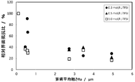
- the cation exchange resin layer preferably has a first surface having a roughness factor of 3 or more.
- the interface resistance of the first surface of the cation exchange resin layer is reduced, and the high-rate discharge performance of the nonaqueous electrolyte secondary battery is improved.
- the arithmetic average roughness Ra of the first surface of the cation exchange resin layer is preferably 0.5 ⁇ m or more.
- the interface resistance can be reduced.
- the maximum height roughness Rz of the first surface of the cation exchange resin layer is preferably 5 ⁇ m or more.
- the maximum height roughness Rz of the first surface of the cation exchange resin layer is 5 ⁇ m or more, even when the electrolyte salt concentration is low, the interface resistance of the first surface of the cation exchange resin layer can be reduced.
- the non-aqueous electrolyte secondary battery may further include a porous layer.
- the porous layer is preferably in contact with the first surface of the cation exchange resin layer.
- a nonaqueous electrolyte secondary battery manufacturing method is a nonaqueous electrolyte secondary battery including a positive electrode containing sulfur, a negative electrode, and a cation exchange resin layer interposed between the positive electrode and the negative electrode.
- a method for producing a battery wherein a positive electrode electrolyte containing lithium polysulfide is injected between a positive electrode and a cation exchange resin layer, and the lithium polysulfide is more interposed between the negative electrode and the cation exchange resin layer than the positive electrode electrolyte. Injecting a negative electrode electrolyte having a low concentration.
- the nonaqueous electrolyte secondary battery according to the first embodiment includes a positive electrode containing sulfur, a negative electrode, a cation exchange resin layer interposed between the positive electrode and the negative electrode, a positive electrode electrolyte, and a negative electrode electrolyte.
- the positive electrode electrolyte is lithium polysulfide.
- concentration of positive electrode electrolyte is higher than the sulfur conversion density
- the positive electrode electrolyte is disposed between the positive electrode and the cation exchange resin layer, and the negative electrode electrolyte is disposed between the cation exchange resin layer and the negative electrode.
- nonaqueous electrolyte used in the nonaqueous electrolyte secondary battery usually includes an electrolyte salt and a nonaqueous solvent.
- a nonaqueous solvent that does not include an electrolyte salt is referred to as a “nonaqueous electrolyte”.
- the cation exchange resin layer is a layer containing a cation exchange resin and serves as a separator that keeps the positive electrode and the negative electrode in an insulating state.
- the cation exchange resin has a structure in which an anionic functional group such as a sulfonic acid group or a carboxylic acid group is bonded to a polymer mainly composed of hydrocarbon. Due to the electrostatic interaction of this anionic group, it has a high cation permeability, while the anion permeability is low. That is, the cation exchange resin allows lithium ions to pass therethrough and slightly dissociates in the positive electrode electrolyte (electrolytic solution) to block the passage of anionic lithium polysulfide. Thereby, since the cation exchange resin layer suppresses the movement of the lithium polysulfide from the positive electrode to the negative electrode, the shuttle phenomenon is suppressed.
- the lithium polysulfide produced at the positive electrode during the charge / discharge reaction is highly soluble in a non-aqueous solvent. Elution easily into the positive electrolyte during the discharge cycle.
- the present inventors By mixing lithium polysulfide in advance with the positive electrode electrolyte disposed between the positive electrode and the cation exchange resin layer, the present inventors only suppress elution of lithium polysulfide produced at the positive electrode.
- the present inventors have found that lithium polysulfide in the positive electrode electrolyte can exhibit excellent energy density and charge / discharge cycle performance by contributing to the charge / discharge reaction as a positive electrode active material.
- the nonaqueous electrolyte secondary battery according to the present embodiment includes a cation exchange resin layer between the positive electrode and the negative electrode, the positive electrode electrolyte includes lithium polysulfide, and the sulfur equivalent concentration of the positive electrode electrolyte is sulfur of the negative electrode electrolyte.
- the sulfur equivalent concentration is a value obtained by converting the concentration of the sulfur compound in the non-aqueous electrolyte into the concentration of sulfur atoms.
- 1 mol / l lithium sulfide corresponds to a sulfur equivalent concentration of 1 mol / l
- 1 mol / l Li 2 S 6 corresponds to a sulfur equivalent concentration of 6 mol / l
- 1 mol / l sulfur corresponds to a sulfur equivalent concentration of 8 mol / l.
- the lower limit of the concentration in terms of sulfur of the positive electrode electrolyte is preferably 1.2 mol / l, more preferably 1.5 mol / l, and even more preferably 3.0 mol / l.
- the sulfur conversion concentration is 1.2 mol / l or more, the charge / discharge efficiency after the charge / discharge cycle is improved.
- the sulfur equivalent concentration is 3.0 mol / l or more, a non-aqueous electrolyte secondary battery having a high capacity and a high energy density can be provided.
- the upper limit of the concentration in terms of sulfur of the positive electrode electrolyte is preferably 18 mol / l, more preferably 12 mol / l, and even more preferably 9 mol / l.
- the sulfur equivalent concentration is not more than the above upper limit, the viscosity of the positive electrode electrolyte does not increase too much and the interface resistance between the positive electrode electrolyte and the cation exchange resin layer does not become too high, so a non-aqueous electrolyte secondary battery with high energy density can be obtained. can get.
- the nonaqueous electrolyte may contain an anion derived from an electrolyte salt.
- the anion in the present embodiment refers to an anion derived from an electrolyte salt dissolved in a non-aqueous electrolyte, an anionic functional group such as a sulfonic acid group contained in the molecular structure of the cation exchange resin, lithium It does not include compounds that are partly dissociated from sulfides and lithium polysulfides and are anionic.
- the upper limit of the concentration of the anion contained in at least one of the positive electrode electrolyte and the negative electrode electrolyte is preferably 0.7 mol / l, more preferably 0.5 mol / l, still more preferably 0.3 mol / l.
- the upper limit of the concentration of the anion contained in the positive electrode electrolyte is preferably 0.3 mol / l, more preferably 0.2 mol / l, and may be 0 mol / l.
- the anion concentration is not more than the above upper limit, it is possible to reduce the viscosity of the nonaqueous electrolyte, and it is possible to obtain a nonaqueous electrolyte secondary battery having a high discharge capacity and excellent charge / discharge cycle performance.
- the lower limit of the concentration of the anion contained in at least one of the positive electrode electrolyte and the negative electrode electrolyte may be 0 mol / l, preferably 0.1 mol / l, and more preferably 0.3 mol / l.
- the lithium polysulfides positive electrolyte contains, but are not limited to, lithium polysulfides represented by Li 2 S n (4 ⁇ n ⁇ 8) are preferred.
- the method for obtaining the lithium polysulfide represented by the composition formula Li 2 Sn (4 ⁇ n ⁇ 8) is not limited.
- the mixture is placed in a sealed container and allowed to react for 4 days or longer in a thermostatic bath at 80 ° C. Can be obtained.
- the negative electrode electrolyte has a lower sulfur equivalent concentration than the positive electrode electrolyte. That is, the sum of the concentrations of elemental sulfur, lithium polysulfide, and Li 2 S contained in the negative electrode electrolyte is lower than that of the positive electrode electrolyte.
- Lithium polysulfide reacts with the negative electrode active material to reduce the charging depth of the negative electrode active material, and produces Li 2 S as a reduction product. Since Li 2 S is insoluble in the non-aqueous solvent, it precipitates on the negative electrode surface and reduces the reaction area of the negative electrode.
- the upper limit of the sulfur equivalent concentration of the negative electrode electrolyte is preferably 0.5 mol / l, and may be 0 mol / l. Since lithium polysulfide is known to react on the negative electrode surface to form a solid electrolyte coating (SEI), the negative electrode electrolyte preferably contains a small amount of lithium polysulfide.
- the positive electrode according to the present embodiment includes a positive electrode base material and a positive electrode mixture layer disposed directly or via an intermediate layer on the positive electrode base material.
- the positive electrode base material a known material can be appropriately used as long as it is an electronic conductor that does not adversely affect the battery.
- the positive electrode base material include aluminum, titanium, stainless steel, nickel, baked carbon, conductive polymer, conductive glass, etc., and aluminum and copper for the purpose of improving adhesiveness, conductivity, and oxidation resistance. Or the like can be used which have been treated with carbon, nickel, titanium, silver or the like.
- the shape of the positive electrode base material a film shape, a sheet shape, a net shape, a punched or expanded material, a lath body, a porous body, a foamed body, a formed body of fiber groups, and the like are used in addition to a foil shape.
- the thickness is not particularly limited, but a thickness of 1 to 500 ⁇ m is used.
- the intermediate layer is a coating layer on the surface of the positive electrode substrate, and reduces the contact resistance between the positive electrode substrate and the positive electrode mixture layer by containing a conductive agent such as carbon particles.
- a conductive agent such as carbon particles.
- the configuration of the intermediate layer is not particularly limited, and can be formed by, for example, a composition containing a binder and a conductive agent.
- the positive electrode mixture layer includes an active material, a conductive agent, and a binder, and the active material includes sulfur.
- the active material sulfur combined with a conductive material is preferably used.
- the conductive substance include carbon materials such as porous carbon, carbon black, graphite, and carbon fiber, and electron conductive polymers such as polyaniline, polythiophene, polyacetylene, and polypyrrole.
- the positive electrode mixture layer may contain an active material other than sulfur, a thickener, a filler, and the like as necessary.
- the positive electrode mixture layer may not contain solid-state sulfur.
- the positive electrode mixture layer contains only the conductive agent and the binder, and the lithium polysulfide in the positive electrode electrolyte contributes to charge / discharge as an active material. It is preferable to contain solid sulfur because the discharge capacity and energy density of the nonaqueous electrolyte secondary battery can be improved.
- any known material can be used as long as it is a positive electrode active material capable of occluding and releasing lithium ions.
- a composite oxide represented by Li x MO y (M represents at least one transition metal) (Li x CoO 2 , Li x NiO 2 , Li x Mn 2 O 4 , Li x MnO 3 , Li x Ni y Co (1-y) O 2 , Li x Ni y Mn z Co (1-yz) O 2 , Li x Ni y Mn (2-y) O 4, etc.), or Li w Me x (XO y ) z (Me represents at least one kind of transition metal, and X represents, for example, P, Si, B, V) polyanion compounds (LiFePO 4 , LiMnPO 4 , LiNiPO 4 , LiCoPO 4 , Li 3 V 2 (PO) 4 ) 3 , Li 2 MnSiO 4 ,
- the elements or polyanions in these compounds may be partially substituted with other elements or anion species, and the surface is coated with a metal oxide such as ZrO 2 , MgO, Al 2 O 3 or carbon. Also good.
- examples include, but are not limited to, conductive polymer compounds such as disulfide, polypyrrole, polyaniline, polyparastyrene, polyacetylene, and polyacene materials, pseudographite-structured carbonaceous materials, and simple sulfur.
- these compounds may be used independently and may mix and use 2 or more types.
- the conductive agent is not limited as long as it is an electron conductive material that does not adversely affect the battery performance.
- natural graphite scale-like graphite, scale-like graphite, like-like graphite
- artificial graphite carbon black
- acetylene black Use of one or a mixture of two or more conductive materials such as ketjen black, carbon whisker, carbon fiber, metal (copper, nickel, aluminum, silver, gold, etc.) powder, metal fiber, and conductive ceramic material it can.
- acetylene black is preferable from the viewpoints of electron conductivity and coatability.
- the addition amount of the conductive agent is preferably 0.1% by mass to 50% by mass and more preferably 0.5% by mass to 30% by mass with respect to the total mass of the positive electrode mixture layer. It is preferable to use acetylene black by pulverizing it into ultrafine particles of 0.1 to 0.5 ⁇ m because the necessary carbon amount can be reduced.
- binders generally used for non-aqueous electrolyte secondary batteries can be used.
- thermoplastic resins such as polytetrafluoroethylene (PTFE), polyvinylidene fluoride (PVDF), polyethylene, and polypropylene
- PTFE polytetrafluoroethylene
- PVDF polyvinylidene fluoride
- EPDM ethylene-propylene-diene terpolymer
- SBR styrene butadiene rubber
- fluororubber ethylene-propylene-diene terpolymer
- the addition amount of the binder is preferably 1 to 50% by mass, and more preferably 2 to 30% by mass with respect to the total mass of the positive electrode mixture layer.
- the thickener examples include polysaccharide polymers such as carboxymethylcellulose (CMC) and methylcellulose.
- CMC carboxymethylcellulose
- methylcellulose a functional group that reacts with lithium
- the filler is not particularly limited as long as it does not adversely affect the battery performance.
- the main component of the filler include polyolefins such as polypropylene and polyethylene, silica, alumina, zeolite, and glass.
- the negative electrode according to the present embodiment includes a negative electrode substrate and a negative electrode mixture layer disposed on the negative electrode substrate directly or via an intermediate layer.
- the negative electrode mixture layer includes a negative electrode active material and a binder.
- the negative electrode mixture layer may contain a conductive agent, a thickener, a filler, and the like as necessary.
- the intermediate layer of the negative electrode can be the same as the intermediate layer of the positive electrode described above.
- the negative electrode active material used for the negative electrode mixture layer is not particularly limited as long as it is a substance capable of electrochemically occluding and releasing lithium ions, and a known material can be appropriately used.
- Examples thereof include carbonaceous materials, metal oxides such as tin oxide and silicon oxide, metal composite oxides, lithium alloys such as lithium alone and lithium aluminum alloys, and metals that can form alloys with lithium such as Sn and Si.
- Examples of the carbonaceous material include graphite (graphite), cokes, non-graphitizable carbon, graphitizable carbon, fullerene, carbon nanotube, carbon black, activated carbon and the like.
- graphite is preferable as a negative electrode active material because it has an operating potential very close to that of metallic lithium and can realize charge and discharge at a high operating voltage.
- artificial graphite and natural graphite are preferable.
- graphite in which the surface of the negative electrode active material particles is modified with amorphous carbon or the like is desirable because it generates less gas during charging.
- These may be used individually by 1 type, or may use 2 or more types together by arbitrary combinations and a ratio.
- carbonaceous materials or lithium composite oxides are preferably used from the viewpoint of safety.
- the various binders described above can be used.
- the negative mix layer may contain the above-mentioned electrically conductive agent, a thickener, a filler, etc.
- the negative electrode substrate in addition to copper, nickel, iron, stainless steel, titanium, aluminum, calcined carbon, conductive polymer, conductive glass, Al—Cd alloy, etc., adhesion, conductivity, reduction resistance
- a surface of copper or the like treated with carbon, nickel, titanium, silver or the like can be used.
- a film shape, a sheet shape, a net shape, a punched or expanded material, a lath body, a porous body, a foamed body, a formed body of fiber groups, and the like are used in addition to the foil shape.
- the thickness is not particularly limited, but a thickness of 1 to 500 ⁇ m is used.
- the cation exchange resin layer serves as a separator that insulates the positive electrode from the negative electrode.
- the cation exchange resin layer contains a cation exchange resin.
- the cation exchange resin include polyacrylic acid, polymethacrylic acid, polyvinylbenzenesulfonic acid, polybenzenemethanesulfonic acid, and polyacrylamide-2-methyl-1-propanesulfonic acid.
- a cation exchange resin can be obtained by introducing a sulfonic acid group (—SO 3 H), a carboxylic acid group (—COOH), or a hydroxyl group (—OH) into various resins.
- Examples of the various resins include perfluorocarbon resins, aromatic polyether ketone resins, polyphenylene sulfide resins, polyether sulfone resins, polyphenylene oxide resins, and polybenzimidazole resins.
- a perfluorocarbon sulfonic acid resin in which a sulfonic acid group is introduced into the perfluorocarbon resin is preferable because high ion conductivity is obtained.
- the form in which the cation exchange resin layer contains the cation exchange resin is not particularly limited.
- a cation exchange membrane in which a cation exchange resin is formed into a film may be used, or a commercially available ion exchange membrane may be used.
- Specific examples of commercially available ion exchange membranes include Nafion membrane (trade name, manufactured by DuPont), Flemion (trade name, manufactured by Asahi Glass Co., Ltd.), Aciplex (trade name, manufactured by Asahi Kasei Co., Ltd.), and the like.
- the thickness of the cation exchange membrane is preferably 20 to 180 ⁇ m.
- the cation exchange resin layer may be a mixture of a cation exchange resin and another polymer formed into a thin film.
- the other polymer materials constituting a porous film described later can be appropriately used.
- the cation exchange resin layer may have a structure in which a cation exchange resin is filled in the porous structure of the porous membrane.
- the filling method is not particularly limited, and examples thereof include a spray method, a dispensing method, a dipping method, and a blade coating method.
- the cation exchange resin layer does not have pores communicating from one surface to the other surface, that is, is non-porous. By being non-porous, the positive electrode electrolyte and the negative electrode electrolyte are not mixed, and the possibility that the lithium polysulfide reaches the negative electrode is reduced. Note that at least one surface may have pores or irregularities that do not communicate with the other surface. Details of such a configuration will be described in the third embodiment.
- a commercially available cation exchange resin or cation exchange membrane is a proton (H + ) type in which a proton is bonded to an anionic functional group.
- H + proton
- a cation exchange resin or a cation exchange membrane When applying a cation exchange resin or a cation exchange membrane to a non-aqueous electrolyte secondary battery, it is preferable to replace the H + type with a lithium (Li + ) type.
- the substitution to the Li + type is performed by immersing the separator in an aqueous lithium hydroxide solution. After immersion, the separator is washed with deionized water at 25 ° C. until the washing water becomes neutral.
- the temperature of the lithium hydroxide aqueous solution is preferably 70 to 90 ° C., and the immersion time is preferably 2 to 6 hours.
- the cation exchange resin layer preferably contains a non-aqueous solvent for the conduction of lithium ions therein.
- a non-aqueous solvent contained in the cation exchange resin layer various non-aqueous solvents that can be used for a positive electrode electrolyte or a negative electrode electrolyte described later can be appropriately used.
- a cation exchange resin layer not containing a non-aqueous solvent may be applied to a non-aqueous electrolyte secondary battery as it is, but some cation exchange resins have a low swelling property of a non-aqueous solvent (or non-aqueous electrolyte). Therefore, it is preferable to perform the swelling treatment with a non-aqueous solvent in advance before battery production.
- the swelling treatment is performed by immersing the cation exchange resin layer substituted with the Li + type in a non-aqueous solvent.
- the swelling treatment time is preferably 12 to 48 hours.
- the amount of the non-aqueous solvent contained in the cation exchange resin layer may be 30% by mass or less based on the cation exchange resin layer.
- a method for adjusting the mass of the nonaqueous solvent contained in the cation exchange resin layer it may be performed by using a nonaqueous solvent with low impregnation into the cation exchange resin, or a nonaqueous solvent in which the cation exchange resin is immersed. You may carry out the quantity of 30 mass% or less previously with respect to the quantity of a cation exchange resin.
- Examples of the solvent having low impregnation property to the cation exchange resin layer include 1,3-dioxane, 1,4-dioxane, 1,2-dimethoxyethane, 1,4-dibutoxyethane, methyl diglyme, dimethyl ether, diethyl
- examples include ethers such as ether, chain carbonates such as dimethyl carbonate, diethyl carbonate, and ethyl methyl carbonate, and cyclic carbonates such as ethylene carbonate, propylene carbonate, and butylene carbonate.
- a nonaqueous solvent used for a positive electrode electrolyte or a negative electrode electrolyte described later can be appropriately used.
- a porous membrane used in a normal nonaqueous electrolyte secondary battery may be used as a separator.
- a porous film a microporous film made of a synthetic resin, a woven or non-woven fabric, a natural fiber, a glass fiber or a ceramic fiber woven or non-woven fabric, paper, or the like can be used.
- Synthetic resins include, for example, polyolefin resins such as polyethylene and polypropylene, polyester resins such as polyethylene terephthalate and polybutylene terephthalate, polyvinylidene fluoride, vinylidene fluoride-hexafluoropropylene copolymer, and fluoride resin.
- a synthetic resin microporous film made of polyolefin resin such as woven fabric, nonwoven fabric, polyethylene or polypropylene, which is insoluble in an organic solvent.
- the porous membrane may be configured by laminating a plurality of microporous membranes having different materials, weight average molecular weights, or porosity, and various microplasticizers, antioxidants, or An appropriate amount of an additive such as a flame retardant may be contained.
- a microporous membrane made of polyethylene and polypropylene a microporous membrane made of polyethylene and polypropylene combined with aramid or polyimide, or a microporous membrane composited with these It is particularly preferable to use a polyolefin-based microporous membrane.
- the thickness of the porous membrane is preferably 5 to 35 ⁇ m.
- the nonaqueous solvent used for the positive electrode electrolyte and the negative electrode electrolyte is not limited, and those generally proposed for use in lithium secondary batteries and the like can be used.
- the non-aqueous solvent include cyclic carbonates such as propylene carbonate, ethylene carbonate, butylene carbonate, chloroethylene carbonate, and vinylene carbonate; cyclic esters such as ⁇ -butyrolactone and ⁇ -valerolactone; dimethyl carbonate, diethyl carbonate, Chain carbonates such as ethyl methyl carbonate; chain esters such as methyl formate, methyl acetate and methyl butyrate; tetrahydrofuran or derivatives thereof; 1,3-dioxane, 1,4-dioxane, 1,2-dimethoxyethane, 1 Ethers such as 1,4-dibutoxyethane and methyldiglyme; nitriles such as acetonitrile and benzonitrile; diox
- the positive electrode electrolyte or the negative electrode electrolyte may contain an additive.
- an electrolyte additive generally used for a nonaqueous electrolyte secondary battery can be used.
- aromatic compounds such as biphenyl, alkylbiphenyl, terphenyl, partially hydrogenated terphenyl, cyclohexylbenzene, t-butylbenzene, t-amylbenzene, diphenylether, dibenzofuran; 2-fluorobiphenyl, o-cyclohexylfluorobenzene , Fluorinated anisole compounds such as 2,4-difluoroanisole, 2,5-difluoroanisole, 2,6-difluoroanisole, and 3,5-difluoroanisole; Cyclic hydrocarbons such as vinylene carbonate, methyl vinylene carbonate, ethyl vinylene carbonate, fluoroethylene carbonate, difluoro
- electrolyte salt contained in the positive electrode electrolyte or the negative electrode electrolyte known electrolyte salts can be appropriately used.
- An inorganic ion salt containing one of sodium (Na) or potassium (K) LiCF 3 SO 3 , LiN (CF 3 SO 2 ) 2 , LiN (C 2 F 5 SO 2 ) 2 , LiN (CF 3 SO 2) (C 4 F 9 SO 2), LiC (CF 3 SO 2) 3, LiC (C 2 F 5 SO 2) 3, (CH 3) 4 NBF 4, (CH 3) 4 NBr, (C 2 H 5) 4 NClO 4, (C 2 H 5) 4 NI, (C 3 H 7) 4 NBr, (n-C 4 H 9) 4
- the viscosity of the electrolyte can be lowered.
- the performance can be improved, and self-discharge can be suppressed, which is more preferable.
- the non-aqueous electrolyte may contain a room temperature molten salt or an ionic liquid.
- a positive electrode electrolyte containing lithium polysulfide is injected between the positive electrode and the cation exchange resin layer, and between the negative electrode and the cation exchange resin layer, Injecting a negative electrode electrolyte having a concentration of lithium polysulfide lower than that of the positive electrode electrolyte.
- the manufacturing method includes, for example, (1) a step of producing a positive electrode, (2) a step of producing a negative electrode, (3) a step of preparing a positive electrode electrolyte and a negative electrode electrolyte, and (4) a cation exchange resin layer as a non-aqueous electrolyte or A step of immersing in a non-aqueous solvent, (5) a step of injecting a positive electrode electrolyte between the positive electrode and the cation exchange resin layer, (6) a step of injecting a negative electrode electrolyte between the negative electrode and the cation exchange resin layer, (7 ) A step of forming an electrode group in which the positive electrode and the negative electrode are alternately superimposed by stacking or winding the cation exchange resin layer, and (8) The positive electrode and the negative electrode (electrode group) are accommodated in a battery container (case).
- the positive electrode electrolyte prepared in the step (3) contains at least lithium polysulfide, and the negative electrode electrolyte has a lower sulfur equivalent concentration than the positive electrode electrolyte.
- the positive electrode electrolyte preferably has a sulfur equivalent concentration of 1.2 mol / l or more, more preferably 1.5 mol / l or more, and even more preferably 3.0 mol / l or more.
- the step (5) may be performed by dropping the positive electrode electrolyte directly on the positive electrode, or by placing a porous layer or the like impregnated with the positive electrode electrolyte between the positive electrode and the cation exchange resin layer. Also good.
- the steps (1) to (4) may be performed in any order, and the steps (5) to (7) may be performed simultaneously or sequentially.
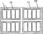
- non-aqueous electrolyte secondary battery of the present embodiment for example, a non-aqueous electrolyte secondary battery 1 (lithium ion secondary battery) shown in FIG.
- the nonaqueous electrolyte secondary battery 1 includes a container 3, a positive electrode terminal 4, and a negative electrode terminal 5, and the container 3 is a container main body and an upper wall that accommodate the electrode group 2 and the like. And a cover plate.
- an electrode group 2, a positive electrode lead 4 ', and a negative electrode lead 5' are arranged inside the container body.
- the positive electrode 11 is electrically connected to the positive electrode terminal 4 via the positive electrode lead 4 ′, and the negative electrode 13 is electrically connected to the negative electrode terminal 5 via the negative electrode lead 5 ′.
- the positive electrode 11 is impregnated with the positive electrode electrolyte and the negative electrode 13 is impregnated with the negative electrode electrolyte, the liquid is not shown.
- the electrode group 2 includes a positive electrode 11, a negative electrode 13, and a cation exchange resin layer 15 as a separator, and can store electricity. Specifically, as shown in FIG. 2, the electrode group 2 is formed in a layered manner so that the cation exchange resin layer 15 is sandwiched between the negative electrode 13 and the positive electrode 11.
- the electrode group 2 includes a positive electrode electrolyte 12 between the positive electrode 11 and the cation exchange resin layer 15, and a negative electrode electrolyte 14 between the negative electrode 13 and the cation exchange resin layer 15.
- the positive electrode electrolyte 12 contains lithium polysulfide.
- the cation exchange resin layer 15 contains a cation exchange resin.
- the sulfur equivalent concentration of the negative electrode electrolyte 14 is lower than the sulfur equivalent concentration of the positive electrode electrolyte 12.
- FIG. 2 the positive electrode 11 and the positive electrode electrolyte 12, and the negative electrode 13 and the negative electrode electrolyte 14 are shown separately.
- the positive electrode electrolyte 12 and the negative electrode electrolyte 14 are impregnated in the positive electrode 11 and the negative electrode 13, respectively.
- the positive electrode 11 is in contact with one surface of the cation exchange resin layer
- the negative electrode 13 is in contact with the other surface of the cation exchange resin layer 15.
- the positive electrode 11 is in contact with one surface of the cation exchange resin layer 15, and the negative electrode 13 is in contact with the other surface of the cation exchange resin layer 15.
- a porous layer may be disposed between and between the negative electrode 13 and the cation exchange resin layer 15. The porous layer disposed between the positive electrode 11 and the cation exchange resin layer 15 is impregnated with the positive electrode electrolyte, and the porous layer disposed between the negative electrode 13 and the cation exchange resin layer 15 is impregnated with the negative electrode electrolyte. Is done.
- the configuration of the nonaqueous electrolyte secondary battery according to the present invention is not particularly limited, and examples thereof include a cylindrical battery, a square battery (rectangular battery), a flat battery, and the like. It is good also as an electrical storage apparatus provided with two or more said nonaqueous electrolyte secondary batteries.
- a power storage device is shown in FIG. In FIG. 3, the power storage device 100 includes a plurality of power storage units 20. Each power storage unit 20 includes a plurality of nonaqueous electrolyte secondary batteries 1.
- the power storage device 100 can be mounted as a power source for vehicles such as an electric vehicle (EV), a hybrid vehicle (HEV), a plug-in hybrid vehicle (PHEV), and the like.
- the nonaqueous electrolyte secondary battery according to the second embodiment includes a positive electrode containing sulfur, a negative electrode, a cation exchange resin layer interposed between the positive electrode and the negative electrode, and a nonaqueous electrolyte, and at least one of the positive electrode and the negative electrode is a cation.
- An exchange resin is provided, and the concentration of anions contained in the nonaqueous electrolyte is 0.7 mol / l or less.
- the non-aqueous electrolyte secondary battery according to the second embodiment includes a positive electrode containing sulfur, a negative electrode, a cation exchange resin layer interposed between the positive electrode and the negative electrode, and between the positive electrode and the cation exchange resin layer.
- a positive electrode electrolyte (an example of a non-aqueous electrolyte) disposed, and a negative electrode electrolyte (an example of a non-aqueous electrolyte) disposed between a negative electrode and a cation exchange resin layer, wherein at least one of the positive electrode and the negative electrode comprises a cation exchange resin.
- concentration of anions contained in the positive electrode electrolyte and the negative electrode electrolyte is 0.7 mol / l or less.
- At least one of the positive electrode and the negative electrode includes a cation exchange resin.
- a cation exchange resin is not specifically limited, It is preferable to provide on the surface or inside of a positive mix layer or a negative mix layer. That is, the aspect which a cation exchange resin covers the surface of a mixture layer may be sufficient, and the aspect which exists in at least one part inside a mixture layer may be sufficient.
- the cation exchange resin allows only cations to pass and inhibits the passage of anions. Therefore, the transport number of lithium ions in the cation exchange resin is approximately 1. That is, the cation exchange resin is a single ion conductor.
- the transport number of lithium ions in a non-aqueous electrolyte containing a lithium salt since both lithium ions and counter anions move, the transport number of lithium ions is not 1, and the non-aqueous electrolyte is not a single ion conductor.
- the interface resistance is large at the interface between the nonaqueous electrolyte and the cation exchange resin layer.
- a cation exchange resin is contained in at least one of the positive electrode and the negative electrode, so that a lithium conduction path made of the cation exchange resin is formed between the cation exchange resin layer and the positive electrode active material or the negative electrode active material.
- the positive electrode according to the second embodiment includes a positive electrode base material and a positive electrode mixture layer formed directly or via an intermediate layer on the positive electrode base material.
- the configurations of the positive electrode substrate and the intermediate layer are the same as those in the first embodiment.
- the positive electrode mixture layer includes a positive electrode active material, a conductive agent, a binder, and a cation exchange resin.
- the positive electrode mixture layer may contain a thickener, a filler, and the like as necessary.
- the positive electrode active material, the conductive agent, the binder, the thickener, the filler, and the like the materials described in the first embodiment can be used.
- the cation exchange resin provided in the positive electrode mixture layer is preferably 10% by mass to 150% by mass with respect to the total mass of the positive electrode mixture layer. It is preferable that the amount of the cation exchange resin is 10% by mass to 150% by mass with respect to the total mass of the positive electrode mixture layer because a continuous lithium ion conduction channel can be formed in the positive electrode mixture layer.
- the negative electrode according to the second embodiment includes a negative electrode substrate and a negative electrode mixture layer disposed on the negative electrode substrate directly or via an intermediate layer.
- middle layer can be set as the structure similar to 1st embodiment.
- the negative electrode mixture layer includes a negative electrode active material, a binder, and a cation exchange resin.
- the negative electrode mixture layer may contain a conductive agent, a thickener, a filler, and the like as necessary.
- a negative electrode active material, a binder, a electrically conductive agent, a thickener, and a filler it can be set as the structure similar to 1st embodiment.
- the cation exchange resin provided in the negative electrode mixture layer is preferably 10% by mass to 150% by mass with respect to the total mass of the negative electrode mixture layer. It is preferable that the amount of the cation exchange resin is 10% by mass to 150% by mass with respect to the total mass of the negative electrode mixture layer because a continuous lithium ion conduction channel can be formed in the negative electrode mixture layer.
- the positive electrode in which the cation exchange resin is present in the positive electrode mixture layer can be produced as follows.
- a particulate positive electrode active material, a cation exchange resin, a conductive agent, and a binder are mixed with a dispersion medium such as alcohol or toluene to prepare a positive electrode mixture paste.
- the obtained positive electrode mixture paste is applied to both surfaces of a sheet-like positive electrode substrate, dried and then pressed to produce a positive electrode.
- a powder mixer such as a V-type mixer, an S-type mixer, a scraper, a ball mill, a planetary ball mill, or the like is used.
- a method of using dry or wet mixing is employed.
- the cation exchange resin the materials mentioned in the first embodiment can be used as appropriate.
- a negative electrode containing a cation exchange resin inside the negative electrode mixture layer can also be produced by the above-described method.
- a cation exchange resin covers the positive electrode or negative electrode surface by apply
- cation exchange resin exists in the mixture layer surface and inside because the solution containing a cation exchange resin permeates the inside of the mixture layer.
- the method for applying a solution containing a cation exchange resin include a spray method, a dispensing method, a dipping method, and a blade coating method.
- the cation exchange resin may be contained in at least one of the positive electrode and the negative electrode, but is preferably contained in the positive electrode, and may be contained in both the positive electrode and the negative electrode.
- the lithium polysulfide produced at the positive electrode during the charge / discharge reaction is suppressed from being eluted into the positive electrode electrolyte in the vicinity of the positive electrode, and the capacity of the positive electrode is unlikely to decrease.
- the cation exchange resin in the positive electrode and the negative electrode a lithium ion conduction path is formed by the cation exchange resin from the positive electrode through the cation exchange resin layer to the negative electrode. High discharge capacity and charge / discharge efficiency can be achieved.
- the positive electrode or negative electrode containing the cation exchange resin and the cation exchange resin layer may be provided integrally. That is, it is good also as an aspect by which the cation exchange resin layer is adhere
- concentration of the anion contained in a nonaqueous electrolyte is 0.7 mol / l or less.
- the non-aqueous electrolyte includes an electrolyte salt composed of a cation and an anion, a non-aqueous solvent, and optionally an additive.
- the non-aqueous electrolyte refers to a positive electrode electrolyte and a negative electrode electrolyte. That is, in this embodiment, the concentration of anions contained in both the positive electrode electrolyte and the negative electrode electrolyte is 0.7 mol / l or less.
- the anion in the present embodiment refers to an anion derived from an electrolyte salt dissolved in a non-aqueous electrolyte, an anionic functional group such as a sulfonic acid group contained in the molecular structure of the cation exchange resin, lithium It does not include compounds in which a part of sulfide and lithium polysulfide is dissociated and anionic.
- the electrolyte salt, the non-aqueous solvent, and the additive can have the same configuration as in the first embodiment.
- the upper limit of the concentration of anions contained in the non-aqueous electrolyte is 0.7 mol / l, preferably 0.5 mol / l, and more preferably 0.3 mol / l.
- the upper limit of the concentration of the anion contained in the positive electrode electrolyte is preferably 0.3 mol / l, more preferably 0.2 mol / l, and may be 0 mol / l.
- the anion concentration is not more than the above upper limit, it is possible to reduce the viscosity of the nonaqueous electrolyte, and it is possible to obtain a nonaqueous electrolyte secondary battery having a high discharge capacity and excellent charge / discharge cycle performance.
- the lower limit of the concentration of the anion contained in the nonaqueous electrolyte may be 0 mol / l, but is preferably 0.1 mol / l, more preferably 0.3 mol / l. By including a small amount of anion in the nonaqueous electrolyte, excellent charge / discharge cycle performance can be obtained.
- the positive electrode electrolyte according to the second embodiment may contain lithium polysulfide, and the sulfur-equivalent concentration of the negative electrode electrolyte may be lower than that of the positive electrode electrolyte.
- the porous membrane may be impregnated with at least one of the positive electrode electrolyte and the negative electrode electrolyte and disposed between the positive electrode and the cation exchange resin layer, or between the negative electrode and the cation exchange resin layer.
- the porous membrane the same configuration as the porous membrane described in the first embodiment can be adopted.
- the kind of the cation exchange resin included in the cation exchange resin layer according to the second embodiment, the form of the cation exchange resin layer, and the like can be the same as those in the first embodiment.
- the nonaqueous electrolyte secondary battery of the second embodiment can be produced in the same manner as the nonaqueous electrolyte secondary battery of the first embodiment, except that it includes a step of incorporating a cation exchange resin into the positive electrode or the negative electrode. That is, the method for producing a nonaqueous electrolyte secondary battery according to the second embodiment includes a cation exchange resin in at least one of the positive electrode and the negative electrode in the step (1) of producing a positive electrode or (2) the step of producing a negative electrode.
- (1) a step of including a cation exchange resin in at least one of the positive electrode and the negative electrode may be included after the step of (1) preparing the positive electrode or (2) preparing the negative electrode.
- the nonaqueous electrolyte secondary battery according to the second embodiment may have the same configuration as the nonaqueous electrolyte secondary battery according to the first embodiment. That is, the nonaqueous electrolyte secondary battery 1 includes a container 3, a positive electrode terminal 4, and a negative electrode terminal 5, and the container 3 includes a container body that houses the electrode group 2 and the like, and a lid plate that is an upper wall. ing. In addition, an electrode group 2, a positive electrode lead 4 ′, and a negative electrode lead 5 ′ are arranged inside the container body. As shown in FIG.
- the electrode group 2 includes a positive electrode electrolyte 12 (an example of a nonaqueous electrolyte) between the positive electrode 11 and the cation exchange resin layer 15, and a negative electrode between the negative electrode 13 and the cation exchange resin layer 15.
- An electrolyte 14 (an example of a non-aqueous electrolyte) is provided.
- the cation exchange resin layer 15 contains a cation exchange resin.
- At least one of the positive electrode 11 and the negative electrode 13 contains a cation exchange resin.
- the concentration of the anion contained in the positive electrode electrolyte and the negative electrode electrolyte is 0.7 mol / l or less.
- the positive electrode electrolyte and the negative electrode electrolyte may have the same configuration or different configurations.
- the positive electrode electrolyte may contain lithium polysulfide.
- a plurality of nonaqueous electrolyte secondary batteries according to the second embodiment may be assembled to form the power storage device shown in FIG.
- the nonaqueous electrolyte secondary battery according to the third embodiment includes a positive electrode containing sulfur, a negative electrode, a cation exchange resin layer interposed between the positive electrode and the negative electrode, and a nonaqueous electrolyte.
- the cation exchange resin layer has a roughness factor. Is provided with a first surface of 3 or more.
- the non-aqueous electrolyte includes a positive electrode electrolyte disposed between the positive electrode and the cation exchange resin layer, and a negative electrode electrolyte disposed between the negative electrode and the cation exchange resin layer.
- the roughness factor is the ratio of the actual surface area to the apparent unit surface area (geometric unit area).
- the lower limit of the roughness factor of the first surface which is at least one surface is 3, preferably 4, and more preferably 10.
- the upper limit of the roughness factor of the first surface of the cation exchange resin layer is preferably 20, more preferably 18, and still more preferably 16.
- the first surface of the cation exchange resin layer in the present embodiment has an arithmetic average roughness Ra specified in JIS B 0601: 2013, preferably 0.5 ⁇ m or more, more preferably 2 ⁇ m or more.
- the arithmetic average roughness Ra satisfies the above range, the resistance at the interface between the cation exchange resin layer and the positive electrode can be reduced.
- the arithmetic average roughness Ra is preferably 10 ⁇ m or less, more preferably 8 ⁇ m or less, and even more preferably 5 ⁇ m or less.
- the first surface of the cation exchange resin layer in the present embodiment preferably has a maximum height roughness Rz defined by JIS B 0601: 2013 of 5 ⁇ m or more, and more preferably 10 ⁇ m or more.
- the maximum height roughness Rz is preferably 30 ⁇ m or less, and more preferably 28 ⁇ m or less.
- the roughness factor, arithmetic average roughness Ra, and maximum height roughness Rz of the first surface of the cation exchange resin layer are determined by photographing and measuring the surface of the cation exchange resin layer under the following conditions and performing shape analysis.
- ⁇ Measuring equipment Ultra deep shape measuring microscope VK-8500 (manufactured by Keyence Corporation) Measurement range: 1.04 ⁇ 10 ⁇ 3 cm 2 -Shape analysis application: VK-H1A9 (manufactured by Keyence Corporation)
- Examples of the roughening treatment method in which the roughness factor of the cation exchange resin layer according to the third embodiment is 3 or more include a method of roughening the surface of the cation exchange resin layer with an abrasive such as sandpaper, a sandblasting method, Examples include chemical etching.
- an abrasive such as sandpaper, a sandblasting method
- Examples include chemical etching.
- the abrasive it is preferable to use sandpaper having a grain size of 320 to 1000 for abrasive cloth abrasives specified in JIS R 6010: 2000.
- the thickness of the cation exchange resin layer according to the third embodiment is preferably 20 to 180 ⁇ m, more preferably 30 to 180 ⁇ m.
- the thickness of the cation exchange resin layer can be sufficiently maintained even when the surface roughening treatment is performed, so that handling during battery manufacture becomes easy.
- the energy density of a battery can be improved.
- the cation exchange resin layer may be formed by forming a mixture of a cation exchange resin and other polymer into a thin film and roughening the surface.
- the other polymer the material constituting the porous film described in the first embodiment can be appropriately used.
- the nonaqueous electrolyte secondary battery according to the third embodiment may further include a porous layer. It is preferable that the porous layer is in contact with the first surface of the cation exchange resin layer.
- the porous layer the porous film described in the first embodiment is preferably used.
- the surface of a positive electrode and a negative electrode has the unevenness
- the porous layer containing a polymer is superior in flexibility to the cation exchange resin layer, so that the porous layer is in contact with the first surface of the cation exchange resin layer, so that the positive electrode-porous layer-cation exchange Good contact between the first surfaces of the resin layers or between the first surfaces of the negative electrode, the porous layer, and the cation exchange resin layer is maintained, and lithium ions are transmitted well. Furthermore, since the non-aqueous electrolyte can be held in the porous layer, uneven distribution of the non-aqueous electrolyte in the positive electrode or the negative electrode hardly occurs, and the charge / discharge reaction at the positive electrode or the negative electrode can be made uniform.
- the porous layer may be provided only between the positive electrode and the first surface of the cation exchange resin layer, or may be provided only between the negative electrode and the first surface of the cation exchange resin layer. Alternatively, a porous layer may be provided both between the positive electrode and the cation exchange resin layer and between the negative electrode and the cation exchange resin layer.
- the positive electrode and the negative electrode according to this embodiment can have the same configuration as in the first embodiment.
- the nonaqueous electrolyte according to the present embodiment can have the same configuration as that of the second embodiment.
- the nonaqueous electrolyte secondary battery according to the third embodiment is manufactured by the same method as in the first embodiment, except that it includes a step of setting the roughness factor of at least one surface of the cation exchange resin layer to 3 or more. it can. That is, in the method for producing a non-aqueous electrolyte secondary battery according to the present embodiment, (4) at least one of the cation exchange resin layers at a stage prior to the step of immersing the cation exchange resin layer in the non-aqueous electrolyte or non-aqueous solvent. A step of roughening the surface and setting the roughness factor to 3 or more.
- the nonaqueous electrolyte secondary battery according to the third embodiment may have the same configuration as the nonaqueous electrolyte secondary battery according to the first embodiment. That is, the nonaqueous electrolyte secondary battery 1 includes a container 3, a positive electrode terminal 4, and a negative electrode terminal 5, and the container 3 includes a container body that houses the electrode group 2 and the like, and a lid plate that is an upper wall. ing. In addition, an electrode group 2, a positive electrode lead 4 ′, and a negative electrode lead 5 ′ are arranged inside the container body. A plurality of nonaqueous electrolyte secondary batteries according to the third embodiment may be assembled to form the power storage device shown in FIG.
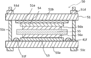
- FIG. 4 shows a local schematic cross-sectional view of the electrode group 2.
- the electrode group 2 includes the positive electrode electrolyte 22 between the positive electrode 21 and the separator 25, and includes the negative electrode electrolyte 24 between the negative electrode 23 and the separator 25.
- the positive electrode electrolyte 22 and the negative electrode electrolyte 24 may be the same or different.
- the separator 25 includes a cation exchange resin layer 25a having a first surface 25c and a second surface 25d and a porous layer 25b, and the first surface 25c and the porous layer 25b are in contact with each other.
- the roughness factor of the first surface 25c of the cation exchange resin layer 25a is 3 or more.
- the positive electrode electrolyte 22 is disposed between the positive electrode 21 and the porous layer 25b, and the negative electrode electrolyte 24 is disposed between the negative electrode 23 and the cation exchange resin layer 25a.
- the positive electrode electrolyte 22 is impregnated in the positive electrode 21 and the porous layer 25b, and the negative electrode electrolyte 24 is impregnated in the negative electrode 23, in a normal battery, the positive electrode 21 is in contact with the porous layer 25b, and the negative electrode 23 is It is in contact with the cation exchange resin layer 25a. That is, in the battery, the positive electrode 21, the porous layer 25b, the cation exchange resin layer 25a, and the negative electrode 23 are laminated in this order.
- the separator 25 has a structure in which a cation exchange resin layer 25a having a first surface 25c and a porous layer 25b are laminated.
- the first surface 25c is in contact with the porous layer 25b.
- the cation exchange resin layer 25a contains a cation exchange resin and suppresses the lithium polysulfide Li 2 S x (4 ⁇ x ⁇ 8) produced at the positive electrode 21 and / or contained in the positive electrode electrolyte 22 from reaching the negative electrode. To do. For this reason, the lithium polysulfide produced at the positive electrode 21 and / or contained in the positive electrode electrolyte 22 is prevented from reaching the negative electrode, and the shuttle phenomenon is suppressed.
- the positive electrode, the porous layer, the cation exchange resin layer, and the negative electrode are arranged in this order, and the roughness factor of the surface in contact with the porous layer, which is the first surface of the cation exchange resin layer
- the roughness factor of the surface in contact with the negative electrode, which is the second surface may be 3 or more. That is, the roughness factors of the first surface and the second surface of the cation exchange resin layer may be 3 or more, respectively.
- the positive electrode, the cation exchange resin layer, the porous layer, and the negative electrode may be arranged in this order, and the roughness factor of the surface of the cation exchange resin layer in contact with the porous layer may be 3 or more.
- the interface resistance of a cation exchange resin layer and a porous layer can be made low.
- the positive electrode electrolyte included in the nonaqueous electrolyte secondary battery according to the third embodiment may include lithium polysulfide, and the sulfur equivalent concentration of the negative electrode electrolyte may be lower than the sulfur equivalent concentration of the positive electrode electrolyte.
- the positive electrode electrolyte contains lithium polysulfide, the interfacial resistance of the cation exchange resin layer tends to increase. However, the interfacial resistance can be suppressed by adopting such a configuration.
- At least one of the positive electrode and the negative electrode included in the nonaqueous electrolyte secondary battery according to the third embodiment may contain a cation exchange resin.
- the cation exchange resin layer and the porous layer are each formed as a single layer, but a plurality of cation exchange resin layers or porous layers may be provided.
- the first surface having a roughness factor of 3 or more may be provided in all the cation exchange resin layers, but may be provided in at least one cation exchange resin layer. This is because the interfacial resistance of the cation exchange resin layer can be lowered and the high rate discharge performance of the battery can be improved.
- Example 1-1 Magnesium citrate was carbonized at 900 ° C. in an argon atmosphere for 1 hour, and then immersed in a 1 mol / l sulfuric acid aqueous solution to extract magnesium oxide (MgO). The residue was washed and dried to obtain porous carbon. This porous carbon and sulfur were mixed at a mass ratio of 30:70. The mixture was sealed in a sealed container under an argon atmosphere, heated to 150 ° C. at a heating rate of 5 ° C./min, held for 5 hours, and then allowed to cool to 80 ° C. Thereafter, the temperature was raised again to 300 ° C. at a heating rate of 5 ° C./min, and heat treatment was performed for 2 hours to obtain a carbon-sulfur composite (hereinafter also referred to as “SPC composite”).
- SPC composite carbon-sulfur composite
- An agent paste was prepared.
- the obtained positive electrode mixture paste was filled in a nickel mesh current collector and dried to prepare a positive electrode.
- a Nafion membrane manufactured by Sigma-Aldrich was substituted from the H + type to the Li + type. That is, the H + -type Nafion membrane was immersed in a 1 mol / l lithium hydroxide water / alcohol solution and stirred at 80 ° C. for 12 hours to exchange protons with lithium ions. The Nafion membrane after stirring was washed with deionized water and dried under vacuum at 120 ° C. to remove lithium hydroxide and the solvent.
- the obtained Li + -type Nafion membrane was swelled by immersing it in a solution in which 1,2-dimethoxyethane (DME) and 1,3-dioxolane (DOL) were mixed at a volume ratio of 50:50.
- DME 1,2-dimethoxyethane
- DOL 1,3-dioxolane
- the Nafion membrane after the swelling treatment was impregnated with 20% by mass of a non-aqueous electrolyte with respect to the mass of the Nafion membrane before the swelling treatment.
- the thicknesses of the Nafion membrane before and after the swelling treatment were 50 ⁇ m and 64 ⁇ m, respectively.
- a metal foil was attached to a copper foil having a thickness of 10 ⁇ m so that the total thickness of the negative electrode was 310 ⁇ m.
- the positive electrode electrolyte was produced as follows. In a glove box with a dew point of ⁇ 80 ° C. or less, DME and lithium polysulfide (Li 2 S) and sulfur (S 8 ) are in a stoichiometric ratio (molar ratio 8: 5) that Li 2 S 6 can produce. DOL and a non-aqueous electrolyte mixed at a volume ratio of 50:50 were added and stirred. This solution was sealed in an airtight container and left in a constant temperature bath at 80 ° C. for 4 days to react Li 2 S with S 8 . The obtained lithium polysulfide solution was used as a positive electrode electrolyte. In this lithium polysulfide solution, lithium polysulfide equivalent to 3.0 mol / l in terms of sulfur is dissolved.
- DME and DOL were mixed at a volume ratio of 50:50.
- the test cell 30 was produced using the electrochemical measurement cell 31 (manufactured by Nippon Tomcell) shown in FIG. First, the positive electrode 33 manufactured as described above is placed inside an O-ring 31f having an inner diameter of 26 mm and an outer diameter of 34 mm provided on a stainless steel plate support 31a. After dropping the positive electrode electrolyte, a cation exchange resin layer 35 having a size larger than the inner diameter of the O-ring was disposed. A negative electrode 34 impregnated with a negative electrode electrolyte was disposed thereon.
- a test cell 30 (hereinafter also referred to as a “battery”) is formed by placing an electrode 31e made of a stainless steel plate on the negative electrode 34, and overlapping a stainless steel plate lid 31b and fastening a bolt 31c and a nut 31d. Assembled.
- Example 1-5 Magnesium citrate was carbonized at 900 ° C. under an argon atmosphere for 1 hour, and then immersed in a 1 mol / l sulfuric acid aqueous solution to extract MgO. Subsequently, washing and drying were performed to obtain porous carbon. A positive electrode material mixture paste containing this porous carbon, acetylene black, and PVDF in a mass ratio of 85: 5: 10 and using NMP as a solvent was prepared. The obtained positive electrode mixture paste was filled in a nickel mesh current collector and dried to prepare a positive electrode. A battery of Example 1-5 was made in the same manner as Example 1-1, except that the positive electrode thus prepared was used.
- a battery of Comparative Example 1-2 was fabricated.
- the initial discharge capacities of the batteries of Examples 1-1 to 1-5 and Comparative Examples 1-1 to 1-5, and the capacity retention rate and charge / discharge efficiency at the fifth cycle were measured by the following method.
- a constant current discharge of 0.1 CA was performed up to 1.0 V at 25 ° C.
- constant current charging at 0.1 CA up to 3.0 V was performed at 25 ° C.
- the charge and discharge termination conditions were set until the set voltage was reached or 10 hours had passed. That is, the charging / discharging conditions of the present embodiment is a charge / discharge test with a so-called capacity limiting condition that terminates charging or discharging even when the charging or discharging end voltage is not reached when a certain amount of electricity is applied. .
- the value obtained by dividing the discharge capacity at this time by the mass of the positive electrode active material contained in the positive electrode mixture layer was defined as the initial discharge capacity.
- 1CA is included in the positive electrode when the capacity per mass of the positive electrode active material is 1675 mAh / g, which is the theoretical capacity per mass of sulfur.
- the capacity of the positive electrode active material to be discharged was set to a current value for discharging in 1 hour.
- 1CA was set to a current value of 1000 mA / g with respect to the mass of the porous carbon contained in the positive electrode.
- the above-described discharging and charging steps were taken as one cycle, and this cycle was repeated 6 cycles.
- the cycle capacity retention rate was calculated by dividing the discharge capacity at the fifth cycle by the initial discharge capacity. Further, the charge / discharge efficiency of the fifth cycle was calculated by dividing the discharge capacity of the sixth cycle by the charge capacity of the fifth cycle.
- Table 1 shows the cycle capacity retention rates and charge / discharge efficiencies after 5 cycles of the batteries of Examples 1-1 to 1-5 and Comparative Examples 1-1 to 1-5.
- the batteries of Examples 1-1 to 1-5 all have a cycle capacity retention rate of 5% and a Coulomb efficiency after 5 cycles of 100% or more, and clearly have excellent cycle performance. It became. This is because the lithium polysulfide contained in the positive electrode electrolyte did not reach the negative electrode due to the use of the cation exchange resin layer as a separator, and self-discharge was suppressed. Since 5 mol / l or more of lithium polysulfide was contained, it is considered that the lithium polysulfide produced in the positive electrode was suppressed from being eluted into the positive electrode electrolyte.
- Example 1-1 a comparison was made using a solution containing 1.0 mol / l lithium salt and a sulfur-converted concentration of 3.0 mol / l lithium polysulfide for the positive and negative electrode electrolytes (non-aqueous electrolyte), and a cation exchange membrane for the separator.
- Example 1-1 since the resistance was high and the charge / discharge end voltage was reached immediately after the start of charge / discharge, charging / discharging could not be performed. This is presumably because the conduction mechanism of lithium ions differs between the non-aqueous electrolyte and the cation exchange membrane.
- the lithium ion transport number is 1.
- the lithium ion transport number is smaller than that in the cation exchange membrane.
- a resistance measurement cell 40 was prepared using an electrochemical measurement cell 41 (manufactured by Nippon Tomcell) shown in FIG.
- a stainless steel plate electrode 41e and a porous membrane (porous layer) 46 sandwich a cation exchange resin layer 45 inside an O-ring 41f having an inner diameter of 26 mm and an outer diameter of 34 mm provided on a stainless steel plate support 41a. Laminated.
- a resistance measuring cell 40 was assembled by stacking a stainless steel plate lid 41b on the laminate and fastening bolts 41c and nuts 41d.
- the porous film 46 a polyethylene microporous film having a thickness of 25 ⁇ m impregnated with nonaqueous electrolytes having various lithium salt concentrations was used.
- the cation exchange resin layer 45 has a Nafion membrane (manufactured by Sigma-Aldrich) impregnated with a mixed solvent in which 1,2-dimethoxyethane (DME) and 1,3-dioxolane (DOL) are mixed at a volume ratio of 50:50. Was used.
- the thickness of the Nafion membrane before and after impregnation with the solution was 50 and 64 ⁇ m, respectively.
- the lithium salt concentration of the non-aqueous electrolyte impregnated in the porous membrane 46 is 0.01, 0.1, 0.5, 0.7 and 1.0 mol / l.
- the lithium salt includes lithium bis (trifluoromethanesulfonyl).
- Imido LiTFSI
- DME 1,2-dimethoxyethane
- DOL 1,3-dioxolane
- the electrolyte layer resistance R was measured by AC impedance measurement. The AC impedance measurement was performed at an applied voltage amplitude of 5 mV and a frequency of 1 MHz to 100 mHz.
- the electrolyte layer resistance R is the resistance of the porous layer Re, which is the resistance of the polyethylene microporous membrane, the interface resistance Ri, which is the resistance of the interface between the polyethylene microporous membrane and the cation exchange membrane after the impregnation treatment, and the cation after the impregnation treatment.
- the cation exchange resin layer resistance Rc which is the resistance of the exchange membrane, is included and is represented by the following formula (1).
- a non-aqueous electrolyte adjusted to be 1, 0.5, 0.7 and 1.0 mol / l is impregnated into a polyethylene microporous membrane to produce a resistance measurement cell, and the AC impedance measurement is performed in the same manner. Carried out.
- the resistance obtained by this measurement was defined as a porous layer resistance Re.
- the interface resistance Ri at each lithium salt concentration was calculated using the formula (1).
- the ratio (%) of the interfacial resistance at each lithium salt concentration was determined by setting the value of the interfacial resistance Ri when the lithium salt concentration was 1.0 mol / l as 100%. The results are shown in Table 2.
- Example 2-1 Magnesium citrate was carbonized at 900 ° C. under an argon atmosphere for 1 hour, and then immersed in a 1 mol / l sulfuric acid aqueous solution to extract MgO. Subsequently, washing and drying were performed to obtain porous carbon. This porous carbon and sulfur were mixed at a mass ratio of 30:70. The mixture was sealed in a sealed container under an argon atmosphere, heated to 150 ° C. at a heating rate of 5 ° C./min, held for 5 hours, and then allowed to cool to 80 ° C. Thereafter, the temperature was raised again to 300 ° C. at a heating rate of 5 ° C./min, and heat treatment was performed for 2 hours to obtain a carbon-sulfur composite (hereinafter also referred to as “SPC composite”).
- SPC composite carbon-sulfur composite
- an NMP solution of Li + type Nafion (solid content 5 mass%), a carbon-sulfur composite as a positive electrode active material, acetylene black as a conductive auxiliary agent, A positive electrode mixture paste containing Nafion as a binder at a mass ratio of 85: 5: 10 was prepared. During mixing, ultrasonic dispersion and vacuum impregnation were performed. The obtained positive electrode mixture paste was filled into a Ni mesh current collector and then dried to produce a positive electrode mixed with Li + -type Nafion. The thickness of the obtained positive electrode was about 80 ⁇ m.
- a copper foil having a thickness of 10 ⁇ m and a metal Li attached to a thickness of 310 ⁇ m was used.
- As the positive electrode electrolyte and the negative electrode electrolyte a solution in which 1,2-dimethoxyethane (DME) and 1,3-dioxolane (DOL) were mixed at a volume ratio of 50:50 was used.
- the cation exchange resin layer was used after replacing the H + type Nafion membrane (manufactured by Sigma-Aldrich) with Li + type and then swelling with the positive electrode electrolyte. By this treatment, the amount of the positive electrode electrolyte impregnated in the Nafion membrane was 20% by mass with respect to the mass of the Nafion membrane.
- the thicknesses of the Nafion membrane before and after the swelling treatment were 50 ⁇ m and 64 ⁇ m, respectively.
- a test cell (hereinafter also referred to as “battery”) having the configuration of FIG. did.
- Example 2-2 A carbon-sulfur composite as a positive electrode active material, acetylene black as a conductive additive, and PVDF as a binder were mixed at a mass ratio of 85: 5: 10, and a positive electrode paste was prepared using NMP as a solvent. . During mixing, ultrasonic dispersion and vacuum impregnation were performed. The obtained positive electrode paste was filled in a Ni mesh current collector and dried. By adding 1 mol / l aqueous lithium hydroxide solution to a water / ethanol solution (20%) of Nafion manufactured by Sigma-Aldrich, until the pH of the solution becomes 7.35, the H + type Nafion is converted into Li + type. Replaced with Nafion.
- the Li + type Nafion contained in this solution was 16.6% by mass.
- the water / alcohol solution of the Li + -type Nafion ionomer, diluted by the addition of water / alcohol mixture until a solid content of 5 wt% was adjusted with water / alcohol solution of Li + -type Nafion ionomer.
- the water / alcohol solution of this Li + type Nafion ionomer was dropped and impregnated so that the Li + type Nafion was 112.5% by mass relative to the mass of the positive electrode mixture layer.
- a positive electrode coated with Li + -type Nafion was obtained by drying at 100 ° C. for 12 hours. The thickness of the obtained positive electrode was about 80 ⁇ m.
- Example 2-2 A battery of Example 2-2 was produced in the same manner as Example 2-1, except that the above positive electrode was used.
- Comparative Example 2-1 A battery of Comparative Example 2-1 was produced in the same manner as in Example 2-1, except that polyvinylidene fluoride (PVDF) was used instead of Nafion as the binder.
- PVDF polyvinylidene fluoride
- a battery of Comparative Example 2-2 was fabricated in the same manner as Comparative Example 2-1, except that the polyethylene microporous membrane was disposed and the positive electrode electrolyte had the same composition as the negative electrode electrolyte.
- a constant current discharge of 0.1 CA was performed up to 1.0 V at 25 ° C. After a 10-minute rest after discharging, constant current charging at 0.1 CA up to 3.0 V was performed at 25 ° C.
- the charge and discharge termination conditions were 10 hours.
- the value obtained by dividing the discharge capacity at the first cycle by the mass of the positive electrode active material was taken as the initial discharge capacity.
- the average closed circuit voltage during the first cycle discharge was determined as the initial average discharge voltage.
- 1CA is the current value at which the capacity of the positive electrode active material is discharged in one hour when the capacity of the positive electrode active material is 1675 mAh / g, which is the theoretical capacity of sulfur.
- the above-described discharging and charging steps were taken as one cycle, and this cycle was repeated 6 cycles.
- the charge / discharge efficiency of the fifth cycle was calculated by dividing the discharge capacity of the sixth cycle by the charge capacity of the fifth cycle. Further, the cycle capacity retention rate was calculated by dividing the discharge capacity at the fifth cycle by the discharge capacity at the first
- the battery including the cation exchange resin in the positive electrode and including the cation exchange resin layer exhibited excellent initial discharge capacity, charge / discharge efficiency at the fifth cycle, and initial average discharge voltage.
- Comparative Example 2-1 in which the positive electrode did not contain a cation exchange resin had low initial discharge capacity and charge / discharge efficiency at the fifth cycle.
- the battery of Comparative Example 2-3 containing a cation exchange resin in the positive electrode and having a polyethylene microporous membrane instead of the cation exchange resin layer has low charge / discharge cycle performance, and the charge / discharge efficiency in the fifth cycle is 66. It was 6%.
- the battery of Comparative Example 2-4 in which the positive electrode does not contain a cation exchange resin and the cation exchange resin layer is impregnated with a nonaqueous electrolyte containing 1 mol / l LiTFSI does not provide a sufficient discharge capacity, and the average discharge voltage is also low. It was low.
- High initial discharge capacity and high charge / discharge efficiency by including a cation exchange resin in at least one of the positive electrode and the negative electrode, including a cation exchange resin layer, and the concentration of anions contained in the nonaqueous electrolyte being 0.7 mol / l or less
- the mechanism by which can be obtained is considered as follows.
- the cation exchange resin allows only cations to pass and inhibits the passage of anions. Therefore, the transport number of lithium ions in the cation exchange resin is approximately 1. That is, the cation exchange resin is a single ion conductor.
- Example 2-1 and Example 2-2 at least one of the positive electrode and the negative electrode and the separator contains a cation exchange resin, and the anion concentration in the nonaqueous electrolyte is as low as 0.7 mol / l or less. Since the space can be regarded as a single ion conductor, and the lithium ion transport number is constant and high, high charge / discharge efficiency and discharge capacity can be obtained.
- ⁇ Third embodiment> (Preliminary experiment) The interface resistance between the porous membrane and the cation exchange resin layer when the concentration of lithium polysulfide in the nonaqueous electrolyte impregnated in the porous membrane was changed was measured by the following method.
- the resistance measurement cell 40 shown in FIG. 6 was used for the measurement.
- As the porous film 46 a polyethylene microporous film having a thickness of 25 ⁇ m and impregnated with lithium polysulfide solutions having various sulfur equivalent concentrations was used.
- the cation exchange resin layer 45 is made of a Nafion membrane (manufactured by Sigma-Aldrich) impregnated with a mixed solvent (volume ratio 50:50) of 1,2-dimethoxyethane (DME) and 1,3-dioxolane (DOL). Using. The thicknesses of the Nafion membrane before and after impregnation with the mixed solvent were 50 and 64 ⁇ m, respectively. The sulfur equivalent concentration of the lithium polysulfide solution was 3.0, 6.0, 12.0 and 18.0 mol / l.
- a non-aqueous solvent contained in the lithium polysulfide solution As a non-aqueous solvent contained in the lithium polysulfide solution, a mixture (volume ratio 50:50) of 1,2-dimethoxyethane (DME) and 1,3-dioxolane (DOL) was used.
- DME 1,2-dimethoxyethane
- DOL 1,3-dioxolane
- Table 4 a resistance measurement cell was similarly produced. The AC impedance of these resistance measurement cells was measured. The measurement was performed at an applied voltage amplitude of 5 mV and a frequency of 1 MHz to 100 mHz.
- the interface resistance was calculated in the same manner as in the preliminary experiment of the second example. Table 4 shows the calculation results.
- Example 3-1 Magnesium citrate was carbonized at 900 ° C. under an argon atmosphere for 1 hour, and then immersed in a 1 mol / l sulfuric acid aqueous solution to extract MgO. The residue was washed and dried to obtain porous carbon. This porous carbon and sulfur were mixed at a mass ratio of 30:70. The mixture was sealed in a sealed container under an argon atmosphere, heated to 150 ° C. at a heating rate of 5 ° C./min, held for 5 hours, and then allowed to cool to 80 ° C. Thereafter, the temperature was raised again to 300 ° C. at a rate of temperature rise of 5 ° C./min, and heat treatment was performed for 2 hours to obtain a carbon-sulfur composite (hereinafter also referred to as SPC composite).
- SPC composite carbon-sulfur composite
- An agent paste was prepared.
- the obtained positive electrode mixture paste was filled in a nickel mesh current collector and dried to prepare a positive electrode.
- a Nafion membrane manufactured by Sigma-Aldrich was substituted from the H + type to the Li + type. That is, the H + -type Nafion membrane was immersed in a 1 mol / l lithium hydroxide water / alcohol solution and stirred at 80 ° C. for 12 hours to exchange protons with lithium ions. The Nafion membrane after stirring was washed with deionized water and dried under vacuum at 120 ° C. to remove lithium hydroxide and the solvent.
- the obtained Li + -type Nafion membrane was swelled by immersing it in a solution in which 1,2-dimethoxyethane (DME) and 1,3-dioxolane (DOL) were mixed at a volume ratio of 50:50.
- DME 1,2-dimethoxyethane
- DOL 1,3-dioxolane
- the Nafion membrane after the swelling treatment was impregnated with 20% by mass of a non-aqueous electrolyte with respect to the mass of the Nafion membrane before the swelling treatment.
- the thicknesses of the Nafion membrane before and after the swelling treatment were 50 ⁇ m and 64 ⁇ m, respectively.
- a metal foil was attached to a copper foil having a thickness of 10 ⁇ m so that the total thickness of the negative electrode was 310 ⁇ m.
- the positive electrode electrolyte was produced as follows. In a glove box with a dew point of ⁇ 80 ° C. or less, DME and lithium polysulfide (Li 2 S) and sulfur (S 8 ) are in a stoichiometric ratio (molar ratio 8: 5) that Li 2 S 6 can produce. DOL and a non-aqueous electrolyte mixed at a volume ratio of 50:50 were added and stirred. This solution was sealed in an airtight container and left in a constant temperature bath at 80 ° C. for 4 days to react Li 2 S with S 8 . The obtained lithium polysulfide solution was used as a positive electrode electrolyte. In this lithium polysulfide solution, lithium polysulfide equivalent to 3.0 mol / l in terms of sulfur is dissolved.
- a test cell 50 was fabricated using an electrochemical measurement cell 51 (manufactured by Nippon Tomcell) shown in FIG. First, the positive electrode 53 produced as described above is placed inside an O-ring 51f having an inner diameter of 26 mm and an outer diameter of 34 mm provided on a stainless steel plate support 51a. After laminating a porous membrane (porous layer) 56a impregnated with the positive electrode electrolyte, a cation exchange resin layer 35 having a size larger than the inner diameter of the O-ring was disposed. A porous film 56b impregnated with a negative electrode electrolyte was disposed thereon, and a negative electrode 54 was laminated.
- a test cell 50 (hereinafter also referred to as “battery”) is formed by disposing a stainless steel plate electrode 51e on the negative electrode 54, and overlapping a stainless steel plate lid 51b and fastening a bolt 51c and a nut 51d. Assembled.
- the porous films 56a and 56b polyethylene microporous films having a thickness of 25 ⁇ m were used.
- Example 3-2 to Example 3-6 Batteries of Example 3-2 to Example 3-6 were fabricated in the same manner as Example 3-1, except that the sulfur equivalent concentration of the positive electrode electrolyte and the LiTFSI concentration were changed as shown in Table 5. .
- Comparative Example 3-1 A battery of Comparative Example 3-1 was produced in the same manner as Example 3-1, except that the concentration in terms of sulfur of the positive electrode electrolyte was 0 mol / l and the concentration of LiTFSI was 0.3 mol / l.
- the initial discharge capacities of the batteries of Examples 3-1 to 3-6 and Comparative Example 3-1 as well as the capacity retention ratio and charge / discharge efficiency at the fifth cycle were measured by the following method.
- a constant current discharge with a final discharge voltage of 1.0 V and a discharge current of 0.1 CA was performed at 25 ° C.
- constant current charging was performed at 25 ° C. with a charge end voltage of 3.0 and a charging current of 0.1 CA.
- a value obtained by dividing the discharge capacity at the first cycle by the mass of the positive electrode active material contained in the positive electrode mixture layer was defined as the initial discharge capacity.
- the initial discharge capacity increased as the sulfur equivalent concentration of the positive electrode electrolyte was increased.
- the initial sulfur utilization rate indicating the utilization rate of sulfur contained in the positive electrode mixture layer and the positive electrode electrolyte is maximized when the sulfur equivalent concentration of the positive electrode electrolyte is 6.0 mol / l.
- the cycle capacity retention rate showed a high value even when the sulfur conversion concentration was 12.0 mol / l.
- the initial discharge capacity and the initial sulfur utilization rate are higher than those in Examples 3-1 to 3-3 that do not contain LiTFSI. Both values were low.
- the lithium salt concentration is preferably less than 0.3 mol / l
- the sulfur equivalent concentration is preferably 3.0 to 12.0 mol / l.
- Example 4-1 As a cation exchange membrane that is an example of a cation exchange resin layer, both sides of a 50 ⁇ m-thick Nafion membrane (manufactured by Sigma Aldrich) are applied to both sides of a P320 having a grain size of 320 ⁇ m of abrasive for abrasive cloth specified in JIS R 6010: 2000 No. sandpaper was used to roughen the surface. The number of times of sandpaper polishing was 80 per side. This membrane is referred to as a cation exchange membrane of Example 4-1.
- Example 4-2 The Nafion film was roughened in the same manner as in Example 4-1, except that P400 sandpaper was used. This membrane is referred to as a cation exchange membrane of Example 4-2.
- Example 4-3 A Nafion film was roughened in the same manner as in Example 4-1, except that P1000 sandpaper was used. This membrane is referred to as a cation exchange membrane of Example 4-3.
- Example 4-4 was carried out in the same manner as in Example 4-3, except that the number of polishing with sandpaper was changed and the roughness factor, arithmetic average roughness Ra, and maximum height roughness Rz were changed to the values shown in Table 6. Cation exchange membranes of ⁇ 4-6 were prepared.
- the obtained Li + -type cation exchange membrane was immersed in a solution in which 1,2-dimethoxyethane (DME) and 1,3-dioxolane (DOL) were mixed at a volume ratio of 50:50 at 25 ° C. for 12 hours.
- DME 1,2-dimethoxyethane
- DOL 1,3-dioxolane
- the impregnation treatment was performed.
- the cation exchange membrane after the impregnation treatment was impregnated with 20% by mass of a nonaqueous solvent based on the mass of the cation exchange membrane before the impregnation treatment.
- the thickness of the cation exchange membrane before and after the impregnation treatment was 50 ⁇ m and 64 ⁇ m, respectively.
- the electrolyte layer resistance R was measured by AC impedance measurement.
- the AC impedance measurement was performed at an applied voltage amplitude of 5 mV and a frequency of 1 MHz to 100 mHz.
- a Nyquist diagram of the measurement results was prepared, and fitting was performed using an equivalent circuit. The value on the low frequency side of the intersection of the curve and the real axis fitted with the arc appearing on the highest frequency side was read and used as the electrolyte resistance R.
- the electrolyte layer resistance R is the resistance of the porous layer Re, which is the resistance of the polyethylene microporous membrane, the interface resistance Ri, which is the resistance of the interface between the polyethylene microporous membrane and the cation exchange membrane after the impregnation treatment, and the cation after the impregnation treatment.
- the cation exchange resin layer resistance Rc which is the resistance of the exchange membrane, is included and is represented by the following formula (2).
- R 2Re + 2Ri + Rc (2)
- the interface resistance Ri was calculated using the formula (1).
- the concentration of LiTFSI in the non-aqueous electrolyte impregnated in the polyethylene microporous membrane was changed to the value shown in Table 7, and the AC impedance measurement was performed using the cation exchange membranes of the Examples and Comparative Examples after the impregnation treatment.
- the interface resistance Ri was calculated. When the LiTFSI concentration was 0.5 mol / l, only Examples 4-1 to 4-3 and Comparative Example 4-1 were measured.
- Example 4-2 Using the cation exchange membrane of Example 4-2 and Comparative Example 4-1, the sulfur equivalent concentration of lithium polysulfide in the nonaqueous electrolyte impregnated in the polyethylene microporous membrane was 3.0 mol / l, and the concentration of LiTFSI Was changed to the values shown in Table 8, AC impedance measurement was performed, and the interface resistance Ri was calculated.
- a nonaqueous electrolyte containing lithium polysulfide was produced as follows. In a glove box with a dew point of ⁇ 80 ° C. or less, DME and lithium polysulfide (Li 2 S) and sulfur (S 8 ) are in a stoichiometric ratio (molar ratio 8: 5) that Li 2 S 6 can produce.
- Table 6 shows the roughness factor, arithmetic average roughness Ra, and maximum height roughness Rz of the cation exchange membrane of each Example and Comparative Example, and the concentrations of the cation exchange membrane, LiTFSI and lithium polysulfide after impregnation were changed.
- Tables 7 and 8 show the interfacial resistance Ri with the polyethylene microporous membrane containing the nonaqueous electrolyte.
- Example 5-1 Magnesium citrate was carbonized at 900 ° C. under an argon atmosphere for 1 hour, and then immersed in a 1 mol / l sulfuric acid aqueous solution to extract MgO. Subsequently, washing and drying were performed to obtain porous carbon. This porous carbon and sulfur were mixed at a mass ratio of 30:70. The mixture was sealed in a sealed container under an argon atmosphere, heated to 150 ° C. at a heating rate of 5 ° C./min, held for 5 hours, and then allowed to cool to 80 ° C. Thereafter, the temperature was raised again to 300 ° C. at a heating rate of 5 ° C./min, and heat treatment was performed for 2 hours to obtain a carbon-sulfur composite (hereinafter also referred to as “SPC composite”).
- SPC composite carbon-sulfur composite
- An agent paste was prepared.
- the obtained positive electrode mixture paste was filled in a nickel mesh current collector and dried to prepare a positive electrode.
- the coating amount of the positive electrode mixture paste was 1.2 mg / cm 2 .
- a metal foil was attached to a copper foil having a thickness of 10 ⁇ m so that the total thickness of the negative electrode was 310 ⁇ m.
- a Nafion membrane which was subjected to a roughening treatment on only one side using a P400 sandpaper, was used.
- a solution containing lithium polysulfide in a sulfur conversion concentration of 3.0 mol / l and a mixture of DME and DOL at a volume ratio of 50:50 was used.
- a test cell 60 was produced using an electrochemical measurement cell 61 (manufactured by Nippon Tomcell) as shown in FIG.
- the positive electrode 63 produced as described above is placed inside an O-ring 61f having an inner diameter of 26 mm and an outer diameter of 34 mm provided on a stainless steel plate support 61a.
- a porous membrane (porous layer) 66 impregnated with the positive electrode electrolyte After laminating a porous membrane (porous layer) 66 impregnated with the positive electrode electrolyte, a cation exchange resin layer 65 having a size larger than the inner diameter of the O-ring was disposed. At this time, the cation exchange resin layer 65 was disposed so that the first surface 65 a subjected to the roughening treatment was in contact with the porous membrane 66.
- a negative electrode 64 impregnated with a negative electrode electrolyte was laminated thereon.
- a test cell 60 (hereinafter also referred to as a “battery”) is formed by disposing a stainless steel plate electrode 61e on the negative electrode 64, overlapping a stainless steel plate lid 61b, and fastening a bolt 61c and a nut 61d. Assembled. This is designated as Example Battery 5-1.
- Comparative Example 5-1 A test cell according to Comparative Example 5-1 was produced in the same manner as in Example 5-1, except that a Nafion membrane that had not been roughened was used as the cation exchange membrane. This is designated as Comparative Example Battery 5-1.
- Example Battery 5-1 and Comparative Example Battery 5-1 Measure the 0.1 C discharge capacity and the 0.2 C discharge capacity of Example Battery 5-1 and Comparative Example Battery 5-1, and divide the 0.2 C discharge capacity by the 0.1 C discharge capacity by the following method. Thus, a 0.2C / 0.1C ratio (%) was calculated.
- a 0.1 C constant current discharge up to 1.5 V at 25 ° C. and a 0.1 C constant current charge up to 3.0 V were performed.
- the charge and discharge termination conditions were set until the set voltage was reached or 10 hours had passed.
- the above-described 0.1 C discharging and charging step was set as one cycle, and this cycle was repeated three times.
- a value obtained by dividing the discharge capacity at the third cycle by the mass of the SPC composite was taken as 0.1 C discharge capacity (mAh / g).
- 1C is a current value at which the capacity of the positive electrode active material is discharged in one hour when the capacity per mass of the SPC composite used as the positive electrode active material is set to 1675 mAh / g which is a theoretical capacity.
- 0.2C constant current discharge to 1.5V and 25C constant current charge to 3.0V were performed at 25 degreeC.
- the charge and discharge termination conditions were until the set voltage was reached or 5 hours had passed.
- the above-described 0.2 C discharging and charging step was set as one cycle, and this cycle was repeated three times.
- a value obtained by dividing the discharge capacity at the third cycle by the mass of the SPC composite was defined as 0.2 C discharge capacity (mAh / g).
- the 0.2C / 0.1C ratio (%) was calculated by dividing the 0.2C discharge capacity by the 0.1C discharge capacity.
- Table 9 shows the 0.1 C discharge capacity, 0.2 C discharge capacity, and 0.2 C / 0.1 C ratio (%) of Example Battery 5-1 and Comparative Battery 5-1.
- FIG. 12 shows the discharge curves of 0.1 C and 0.2 C of Example battery 5-1 and Comparative example battery 5-1.
- Example battery 5-1 exhibited a high discharge capacity of 1150 mAh / g at both 0.1 C and 0.2 C discharge currents, and the 0.2 C / 0.1 C ratio was 100%.
- the comparative battery 5-1 had a 0.1C discharge capacity equivalent to that of the example battery 5-1, but the 0.2C discharge capacity was low, and the 0.2C / 0.1C ratio was 71.7. %Met. This is probably because, in Example Battery 5-1, a cation exchange membrane whose surface was roughened was used as the cation exchange resin layer, so that the interface resistance was lowered and the high rate discharge performance was improved.
- Example battery 5-1 as shown in FIG.
- the discharge potential did not decrease even after 1150 mAh / g discharge corresponding to the capacity of sulfur in the positive electrode active material layer.
- the comparative battery 5-1 as shown in FIG. 12B, a phenomenon in which the discharge potential decreases at the end of discharge was observed. This is presumably because the current distribution on the positive electrode surface became more uniform due to the decrease in the interface resistance of the cation exchange resin layer due to the roughening treatment.
- the surface roughening treatment has improved the retention of lithium polysulfide on the surface of the positive electrode, which contributes to the charge / discharge reaction of lithium polysulfide contained in the positive electrode non-aqueous electrolyte. This is probably because
- the present invention can be applied to electronic devices such as personal computers and communication terminals, non-aqueous electrolyte storage elements such as non-aqueous electric field secondary batteries used as power sources for automobiles, and negative electrodes provided therein.
Abstract
Description
しかしながら、充放電中に正極で生成したリチウム多硫化物(Li2Sn、4≦n≦8)が非水電解質に溶出し、負極に到達して還元されることにより自己放電が進行するシャトル現象が課題となっている。シャトル現象を抑制するために、正極と負極との間にカチオン交換樹脂層を配置する技術が知られている。(特許文献1~3、非特許文献1、2)。 As a positive electrode active material for non-aqueous electrolyte secondary batteries, studies are underway to use sulfur as an alternative to lithium transition metal oxides. Since sulfur has a large theoretical capacity per mass of 1675 mAh / g, it is expected as a next-generation positive electrode active material for higher capacity.
However, the lithium polysulfide (Li 2 Sn , 4 ≦ n ≦ 8) produced at the positive electrode during charge / discharge is eluted into the non-aqueous electrolyte, reaches the negative electrode and is reduced, and self-discharge proceeds. The phenomenon is an issue. In order to suppress the shuttle phenomenon, a technique of arranging a cation exchange resin layer between a positive electrode and a negative electrode is known. (
以下、第一実施形態に係る非水電解質二次電池について説明する。以下で説明する実施の形態は、いずれも本発明の好ましい一具体例を示している。以下の実施の形態で示される数値、形状、材料、構成要素、構成要素の配置位置及び接続形態等は、一例であり、本発明を限定する主旨ではない。また、以下の実施の形態における構成要素のうち、本発明の最上位概念を示す独立請求項に記載されていない構成要素については、より好ましい形態を構成する任意の構成要素として説明される。 <First embodiment>
Hereinafter, the nonaqueous electrolyte secondary battery according to the first embodiment will be described. Each of the embodiments described below shows a preferred specific example of the present invention. The numerical values, shapes, materials, constituent elements, arrangement positions and connecting forms of the constituent elements shown in the following embodiments are merely examples, and are not intended to limit the present invention. In addition, among the constituent elements in the following embodiments, constituent elements that are not described in the independent claims indicating the highest concept of the present invention are described as optional constituent elements that constitute a more preferable embodiment.
正極電解質及び負極電解質の少なくとも一方に含まれるアニオンの濃度の上限は、0.7mol/lが好ましく、0.5mol/lがより好ましく、0.3mol/lがさらに好ましい。正極電解質に含まれるアニオンの濃度の上限は、0.3mol/lが好ましく、0.2mol/lがより好ましく、0mol/lであってもよい。アニオンの濃度が上記上限以下であることにより、非水電解質の粘度を下げることが可能となり、放電容量が高く、充放電サイクル性能に優れた非水電解質二次電池を得ることができる。 The nonaqueous electrolyte (positive electrode electrolyte and negative electrode electrolyte) may contain an anion derived from an electrolyte salt. The anion in the present embodiment refers to an anion derived from an electrolyte salt dissolved in a non-aqueous electrolyte, an anionic functional group such as a sulfonic acid group contained in the molecular structure of the cation exchange resin, lithium It does not include compounds that are partly dissociated from sulfides and lithium polysulfides and are anionic.
The upper limit of the concentration of the anion contained in at least one of the positive electrode electrolyte and the negative electrode electrolyte is preferably 0.7 mol / l, more preferably 0.5 mol / l, still more preferably 0.3 mol / l. The upper limit of the concentration of the anion contained in the positive electrode electrolyte is preferably 0.3 mol / l, more preferably 0.2 mol / l, and may be 0 mol / l. When the anion concentration is not more than the above upper limit, it is possible to reduce the viscosity of the nonaqueous electrolyte, and it is possible to obtain a nonaqueous electrolyte secondary battery having a high discharge capacity and excellent charge / discharge cycle performance.
正極合剤層は、固体状態の硫黄を含まなくてもよい。この場合、正極合剤層は導電剤及び結着剤のみを含有し、正極電解質中のリチウム多硫化物が活物質として充放電に寄与する。固体状硫黄を含有することで、非水電解質二次電池の放電容量及びエネルギー密度を向上させられるため、好ましい。 The positive electrode mixture layer includes an active material, a conductive agent, and a binder, and the active material includes sulfur. As the active material, sulfur combined with a conductive material is preferably used. Examples of the conductive substance include carbon materials such as porous carbon, carbon black, graphite, and carbon fiber, and electron conductive polymers such as polyaniline, polythiophene, polyacetylene, and polypyrrole. The positive electrode mixture layer may contain an active material other than sulfur, a thickener, a filler, and the like as necessary.
The positive electrode mixture layer may not contain solid-state sulfur. In this case, the positive electrode mixture layer contains only the conductive agent and the binder, and the lithium polysulfide in the positive electrode electrolyte contributes to charge / discharge as an active material. It is preferable to contain solid sulfur because the discharge capacity and energy density of the nonaqueous electrolyte secondary battery can be improved.
負極基材の形状については、フォイル状の他、フィルム状、シート状、ネット状、パンチ又はエキスパンドされた物、ラス体、多孔質体、発泡体、繊維群の形成体等が用いられる。厚みの限定は特にないが、1~500μmのものが用いられる。 As the negative electrode substrate, in addition to copper, nickel, iron, stainless steel, titanium, aluminum, calcined carbon, conductive polymer, conductive glass, Al—Cd alloy, etc., adhesion, conductivity, reduction resistance For the purpose, a surface of copper or the like treated with carbon, nickel, titanium, silver or the like can be used.
Regarding the shape of the negative electrode substrate, a film shape, a sheet shape, a net shape, a punched or expanded material, a lath body, a porous body, a foamed body, a formed body of fiber groups, and the like are used in addition to the foil shape. The thickness is not particularly limited, but a thickness of 1 to 500 μm is used.
高いイオン伝導性が得られるため、パーフルオロカーボン樹脂にスルホン酸基を導入したパーフルオロカーボンスルホン酸樹脂が好ましい。 In the present embodiment, the cation exchange resin layer serves as a separator that insulates the positive electrode from the negative electrode. The cation exchange resin layer contains a cation exchange resin. Examples of the cation exchange resin include polyacrylic acid, polymethacrylic acid, polyvinylbenzenesulfonic acid, polybenzenemethanesulfonic acid, and polyacrylamide-2-methyl-1-propanesulfonic acid. Further, a cation exchange resin can be obtained by introducing a sulfonic acid group (—SO 3 H), a carboxylic acid group (—COOH), or a hydroxyl group (—OH) into various resins. Examples of the various resins include perfluorocarbon resins, aromatic polyether ketone resins, polyphenylene sulfide resins, polyether sulfone resins, polyphenylene oxide resins, and polybenzimidazole resins.
A perfluorocarbon sulfonic acid resin in which a sulfonic acid group is introduced into the perfluorocarbon resin is preferable because high ion conductivity is obtained.
カチオン交換樹脂を膜状に形成したカチオン交換膜を用いる場合、カチオン交換膜の厚みは20~180μmが好ましい。20μm以上とすることで、電池製造時のハンドリングが容易となる。また、180μm以下とすることで、電池の内部抵抗が大きなものとなる虞を低減できるとともに、電池のエネルギー密度を向上させることができる。
カチオン交換樹脂層は、カチオン交換樹脂とその他の高分子との混合物を薄膜状に成形したものであってもよい。その他の高分子としては、後述する多孔質膜を構成する材料を適宜用いることができる。 The form in which the cation exchange resin layer contains the cation exchange resin is not particularly limited. A cation exchange membrane in which a cation exchange resin is formed into a film may be used, or a commercially available ion exchange membrane may be used. Specific examples of commercially available ion exchange membranes include Nafion membrane (trade name, manufactured by DuPont), Flemion (trade name, manufactured by Asahi Glass Co., Ltd.), Aciplex (trade name, manufactured by Asahi Kasei Co., Ltd.), and the like. .
When a cation exchange membrane in which a cation exchange resin is formed into a film is used, the thickness of the cation exchange membrane is preferably 20 to 180 μm. When the thickness is 20 μm or more, handling during battery production becomes easy. Moreover, by setting it as 180 micrometers or less, while reducing the possibility that the internal resistance of a battery may become large, the energy density of a battery can be improved.
The cation exchange resin layer may be a mixture of a cation exchange resin and another polymer formed into a thin film. As the other polymer, materials constituting a porous film described later can be appropriately used.
(3)の工程で調整された正極電解質は、少なくともリチウム多硫化物を含み、負極電解質は、正極電解質よりも硫黄換算濃度が低い。正極電解質は、硫黄換算濃度が1.2mol/l以上であることが好ましく、1.5mol/l以上がより好ましく、3.0mol/l以上がさらに好ましい。
(5)の工程は、正極に直接正極電解質を滴下することにより行ってもよいし、正極電解質を含浸させた多孔質層等を正極とカチオン交換樹脂層との間に配置することにより行ってもよい。(6)の工程についても同様である。
上記(1)~(4)の工程はどのような順序で行ってもよく、(5)~(7)の工程は同時に行っても逐次行ってもよい。 In the method for producing a nonaqueous electrolyte secondary battery according to the present embodiment, a positive electrode electrolyte containing lithium polysulfide is injected between the positive electrode and the cation exchange resin layer, and between the negative electrode and the cation exchange resin layer, Injecting a negative electrode electrolyte having a concentration of lithium polysulfide lower than that of the positive electrode electrolyte. The manufacturing method includes, for example, (1) a step of producing a positive electrode, (2) a step of producing a negative electrode, (3) a step of preparing a positive electrode electrolyte and a negative electrode electrolyte, and (4) a cation exchange resin layer as a non-aqueous electrolyte or A step of immersing in a non-aqueous solvent, (5) a step of injecting a positive electrode electrolyte between the positive electrode and the cation exchange resin layer, (6) a step of injecting a negative electrode electrolyte between the negative electrode and the cation exchange resin layer, (7 ) A step of forming an electrode group in which the positive electrode and the negative electrode are alternately superimposed by stacking or winding the cation exchange resin layer, and (8) The positive electrode and the negative electrode (electrode group) are accommodated in a battery container (case). And (9) sealing the opening of the battery container.
The positive electrode electrolyte prepared in the step (3) contains at least lithium polysulfide, and the negative electrode electrolyte has a lower sulfur equivalent concentration than the positive electrode electrolyte. The positive electrode electrolyte preferably has a sulfur equivalent concentration of 1.2 mol / l or more, more preferably 1.5 mol / l or more, and even more preferably 3.0 mol / l or more.
The step (5) may be performed by dropping the positive electrode electrolyte directly on the positive electrode, or by placing a porous layer or the like impregnated with the positive electrode electrolyte between the positive electrode and the cation exchange resin layer. Also good. The same applies to the step (6).
The steps (1) to (4) may be performed in any order, and the steps (5) to (7) may be performed simultaneously or sequentially.
なお、図2では、正極11と正極電解質12、負極13と負極電解質14とを分けて示しているが、正極電解質12及び負極電解質14は、正極11及び負極13にそれぞれ含浸されているため、通常の電池では、正極11はカチオン交換樹脂層15の一方の面に接し、負極13はカチオン交換樹脂層15の他方の面に接している。 A local schematic cross-sectional view of the
In FIG. 2, the
以下、第二実施形態に係る非水電解質二次電池について説明する。以下で説明する実施の形態は、いずれも本発明の好ましい一具体例を示している。以下の実施の形態で示される数値、形状、材料、構成要素、構成要素の配置位置及び接続形態等は、一例であり、本発明を限定する主旨ではない。また、以下の実施の形態における構成要素のうち、本発明の最上位概念を示す独立請求項に記載されていない構成要素については、より好ましい形態を構成する任意の構成要素として説明される。なお、第一実施形態と共通する構成要件については、説明を省略する。 <Second embodiment>
Hereinafter, the nonaqueous electrolyte secondary battery according to the second embodiment will be described. Each of the embodiments described below shows a preferred specific example of the present invention. The numerical values, shapes, materials, constituent elements, arrangement positions and connecting forms of the constituent elements shown in the following embodiments are merely examples, and are not intended to limit the present invention. In addition, among the constituent elements in the following embodiments, constituent elements that are not described in the independent claims indicating the highest concept of the present invention are described as optional constituent elements that constitute a more preferable embodiment. In addition, description is abbreviate | omitted about the component requirements common to 1st embodiment.
本実施形態においては、カチオン交換樹脂が、正極及び負極の少なくとも一方に含まれることにより、カチオン交換樹脂層と正極活物質又は負極活物質との間にカチオン交換樹脂からなるリチウム伝導パスが形成される。すなわち、リチウムイオンは、非水電解質を経由することなく、カチオン交換樹脂層と正極活物質又は負極活物質との間を行き来できることから、カチオン交換樹脂層の界面抵抗を小さくすることができる。これにより、高いエネルギー密度と優れた充放電サイクル性能を有する非水電解質二次電池を得ることができると推測される。 As described above, the cation exchange resin allows only cations to pass and inhibits the passage of anions. Therefore, the transport number of lithium ions in the cation exchange resin is approximately 1. That is, the cation exchange resin is a single ion conductor. On the other hand, in a non-aqueous electrolyte containing a lithium salt, since both lithium ions and counter anions move, the transport number of lithium ions is not 1, and the non-aqueous electrolyte is not a single ion conductor. Thus, since the ion transmission mechanisms are different, the interface resistance is large at the interface between the nonaqueous electrolyte and the cation exchange resin layer.
In this embodiment, a cation exchange resin is contained in at least one of the positive electrode and the negative electrode, so that a lithium conduction path made of the cation exchange resin is formed between the cation exchange resin layer and the positive electrode active material or the negative electrode active material. The That is, since lithium ions can go back and forth between the cation exchange resin layer and the positive electrode active material or the negative electrode active material without going through the nonaqueous electrolyte, the interface resistance of the cation exchange resin layer can be reduced. Thereby, it is estimated that the nonaqueous electrolyte secondary battery which has a high energy density and the outstanding charging / discharging cycling performance can be obtained.
負極合剤層内部にカチオン交換樹脂が含まれている負極も、上述の方法により作製できる。 The positive electrode in which the cation exchange resin is present in the positive electrode mixture layer can be produced as follows. A particulate positive electrode active material, a cation exchange resin, a conductive agent, and a binder are mixed with a dispersion medium such as alcohol or toluene to prepare a positive electrode mixture paste. The obtained positive electrode mixture paste is applied to both surfaces of a sheet-like positive electrode substrate, dried and then pressed to produce a positive electrode. As a method of mixing the positive electrode active material, the cation exchange resin, the conductive agent, the binder, and the like, for example, a powder mixer such as a V-type mixer, an S-type mixer, a scraper, a ball mill, a planetary ball mill, or the like is used. A method of using dry or wet mixing is employed. As the cation exchange resin, the materials mentioned in the first embodiment can be used as appropriate.
A negative electrode containing a cation exchange resin inside the negative electrode mixture layer can also be produced by the above-described method.
なお、本実施形態におけるアニオンとは、非水電解質中に溶解している電解質塩由来のアニオンを指し、カチオン交換樹脂の分子構造中に含まれるスルホン酸基等のアニオン性官能基や、リチウム多硫化物及びリチウム多硫化物の一部が乖離してアニオン性を帯びた化合物は含まない。
電解質塩、非水溶媒、及び添加剤としては、第一実施形態と同様の構成とすることができる。 Furthermore, in 2nd embodiment, the density | concentration of the anion contained in a nonaqueous electrolyte is 0.7 mol / l or less. The non-aqueous electrolyte includes an electrolyte salt composed of a cation and an anion, a non-aqueous solvent, and optionally an additive. Here, the non-aqueous electrolyte refers to a positive electrode electrolyte and a negative electrode electrolyte. That is, in this embodiment, the concentration of anions contained in both the positive electrode electrolyte and the negative electrode electrolyte is 0.7 mol / l or less.
The anion in the present embodiment refers to an anion derived from an electrolyte salt dissolved in a non-aqueous electrolyte, an anionic functional group such as a sulfonic acid group contained in the molecular structure of the cation exchange resin, lithium It does not include compounds in which a part of sulfide and lithium polysulfide is dissociated and anionic.
The electrolyte salt, the non-aqueous solvent, and the additive can have the same configuration as in the first embodiment.
第二実施形態に係る非水電解質二次電池を複数個集合して、図3に示す蓄電装置としてもよい。 The nonaqueous electrolyte secondary battery according to the second embodiment may have the same configuration as the nonaqueous electrolyte secondary battery according to the first embodiment. That is, the nonaqueous electrolyte
A plurality of nonaqueous electrolyte secondary batteries according to the second embodiment may be assembled to form the power storage device shown in FIG.
以下、第二実施形態に係る非水電解質二次電池について説明する。以下で説明する実施の形態は、いずれも本発明の好ましい一具体例を示している。以下の実施の形態で示される数値、形状、材料、構成要素、構成要素の配置位置及び接続形態等は、一例であり、本発明を限定する主旨ではない。また、以下の実施の形態における構成要素のうち、本発明の最上位概念を示す独立請求項に記載されていない構成要素については、より好ましい形態を構成する任意の構成要素として説明される。なお、第一実施形態又は第二実施形態と共通する構成要件については、説明を省略する。 <Third embodiment>
Hereinafter, the nonaqueous electrolyte secondary battery according to the second embodiment will be described. Each of the embodiments described below shows a preferred specific example of the present invention. The numerical values, shapes, materials, constituent elements, arrangement positions and connecting forms of the constituent elements shown in the following embodiments are merely examples, and are not intended to limit the present invention. In addition, among the constituent elements in the following embodiments, constituent elements that are not described in the independent claims indicating the highest concept of the present invention are described as optional constituent elements that constitute a more preferable embodiment. In addition, description is abbreviate | omitted about the component requirements common to 1st embodiment or 2nd embodiment.
・測定機器:超深度形状測定顕微鏡VK-8500(キーエンス社製)
・測定範囲:1.04×10⁻³ cm2
・形状解析アプリケーション:VK-H1A9(キーエンス社製) The roughness factor, arithmetic average roughness Ra, and maximum height roughness Rz of the first surface of the cation exchange resin layer are determined by photographing and measuring the surface of the cation exchange resin layer under the following conditions and performing shape analysis.
・ Measuring equipment: Ultra deep shape measuring microscope VK-8500 (manufactured by Keyence Corporation)
Measurement range: 1.04 × 10 −3 cm 2
-Shape analysis application: VK-H1A9 (manufactured by Keyence Corporation)
通常、正極及び負極の表面は、粒子状の活物質に由来する凹凸を有している。そのため、柔軟性が低いカチオン交換樹脂層を用いた場合、粗面化した第一面と正極又は負極との接触面積が、粗面化していない場合に比べて低下する虞がある。ポリマーを含む多孔質層は、カチオン交換樹脂層に比べて柔軟性に優れているため、多孔質層がカチオン交換樹脂層の第一面に接していることで、正極-多孔質層-カチオン交換樹脂層の第一面間、又は負極-多孔質層-カチオン交換樹脂層の第一面間の接触が良好に保たれ、リチウムイオンが良好に伝達される。さらに、多孔質層に非水電解質を保持させることができるので、正極又は負極中での非水電解質の偏在が起こりにくく、正極又は負極での充放電反応を均一化できる。
なお、多孔質層は、正極とカチオン交換樹脂層の第一面との間のみに設けられてもよいし、負極とカチオン交換樹脂層の第一面との間のみに設けられてもよい。あるいは、正極とカチオン交換樹脂層の間及び負極とカチオン交換樹脂層の間の両方に、多孔質層を設けてもよい。 The nonaqueous electrolyte secondary battery according to the third embodiment may further include a porous layer. It is preferable that the porous layer is in contact with the first surface of the cation exchange resin layer. As the porous layer, the porous film described in the first embodiment is preferably used.
Usually, the surface of a positive electrode and a negative electrode has the unevenness | corrugation originating in a particulate-form active material. Therefore, when a cation exchange resin layer having low flexibility is used, the contact area between the roughened first surface and the positive electrode or the negative electrode may be lower than when the surface is not roughened. Since the porous layer containing a polymer is superior in flexibility to the cation exchange resin layer, the porous layer is in contact with the first surface of the cation exchange resin layer, so that the positive electrode-porous layer-cation exchange Good contact between the first surfaces of the resin layers or between the first surfaces of the negative electrode, the porous layer, and the cation exchange resin layer is maintained, and lithium ions are transmitted well. Furthermore, since the non-aqueous electrolyte can be held in the porous layer, uneven distribution of the non-aqueous electrolyte in the positive electrode or the negative electrode hardly occurs, and the charge / discharge reaction at the positive electrode or the negative electrode can be made uniform.
The porous layer may be provided only between the positive electrode and the first surface of the cation exchange resin layer, or may be provided only between the negative electrode and the first surface of the cation exchange resin layer. Alternatively, a porous layer may be provided both between the positive electrode and the cation exchange resin layer and between the negative electrode and the cation exchange resin layer.
第三実施形態に係る非水電解質二次電池を複数個集合して、図3に示す蓄電装置としてもよい。 The nonaqueous electrolyte secondary battery according to the third embodiment may have the same configuration as the nonaqueous electrolyte secondary battery according to the first embodiment. That is, the nonaqueous electrolyte
A plurality of nonaqueous electrolyte secondary batteries according to the third embodiment may be assembled to form the power storage device shown in FIG.
なお、図4では、正極21と多孔質層25bとの間に正極電解質22が配置され、負極23とカチオン交換樹脂層25aとの間に負極電解質24が配置されている。しかしながら、正極電解質22は、正極21及び多孔質層25bに含浸されており、負極電解質24は負極23に含浸されているため、通常の電池では正極21は多孔質層25bに接し、負極23はカチオン交換樹脂層25aに接している。すなわち、電池内では、正極21、多孔質層25b、カチオン交換樹脂層25a、負極23の順に積層されて配置されている。 FIG. 4 shows a local schematic cross-sectional view of the
In FIG. 4, the
(実施例1-1)
クエン酸マグネシウムを900℃、アルゴン雰囲気下で1時間炭化処理したのち、1mol/lの硫酸水溶液中に浸漬することによって、酸化マグネシウム(MgO)を抽出した。残留物を、洗浄及び乾燥して、多孔性カーボンを得た。この多孔性カーボンと硫黄とを質量比30:70で混合した。この混合物を、アルゴン雰囲気下で密閉容器に封入し、昇温速度5℃/分で150℃まで昇温し、5時間保持した後、80℃まで放冷した。その後、再び昇温速度5℃/分で300℃まで昇温し、2時間保持する熱処理を行い、カーボン-硫黄複合体(以下、「SPC複合体」ともいう)を得た。 <First Example>
Example 1-1
Magnesium citrate was carbonized at 900 ° C. in an argon atmosphere for 1 hour, and then immersed in a 1 mol / l sulfuric acid aqueous solution to extract magnesium oxide (MgO). The residue was washed and dried to obtain porous carbon. This porous carbon and sulfur were mixed at a mass ratio of 30:70. The mixture was sealed in a sealed container under an argon atmosphere, heated to 150 ° C. at a heating rate of 5 ° C./min, held for 5 hours, and then allowed to cool to 80 ° C. Thereafter, the temperature was raised again to 300 ° C. at a heating rate of 5 ° C./min, and heat treatment was performed for 2 hours to obtain a carbon-sulfur composite (hereinafter also referred to as “SPC composite”).
得られたLi+型ナフィオン膜を、1,2-ジメトキシエタン(DME)と1,3-ジオキソラン(DOL)とを体積比50:50で混合した溶液に浸漬することにより、膨潤処理した。この処理により、膨潤処理後のナフィオン膜には、膨潤処理前のナフィオン膜の質量に対して20質量%の非水電解質が含浸された。膨潤処理前後のナフィオン膜の厚みは、それぞれ50μm、64μmであった。 For the cation exchange resin layer, a Nafion membrane manufactured by Sigma-Aldrich was substituted from the H + type to the Li + type. That is, the H + -type Nafion membrane was immersed in a 1 mol / l lithium hydroxide water / alcohol solution and stirred at 80 ° C. for 12 hours to exchange protons with lithium ions. The Nafion membrane after stirring was washed with deionized water and dried under vacuum at 120 ° C. to remove lithium hydroxide and the solvent.
The obtained Li + -type Nafion membrane was swelled by immersing it in a solution in which 1,2-dimethoxyethane (DME) and 1,3-dioxolane (DOL) were mixed at a volume ratio of 50:50. By this treatment, the Nafion membrane after the swelling treatment was impregnated with 20% by mass of a non-aqueous electrolyte with respect to the mass of the Nafion membrane before the swelling treatment. The thicknesses of the Nafion membrane before and after the swelling treatment were 50 μm and 64 μm, respectively.
露点-80℃以下のグローブボックス内で、リチウム多硫化物(Li2S)と硫黄(S8)をLi2S6が生成し得る量論比(モル比8:5)にて、DMEとDOLとを体積比50:50で混合した非水電解質に投入し、撹拌した。この溶液を密閉容器に封入し、80℃の恒温槽内に4日間静置することにより、Li2SとS8とを反応させた。得られたリチウム多硫化物溶液を正極電解質として用いた。このリチウム多硫化物溶液には、硫黄に換算した場合3.0mol/lに相当するリチウム多硫化物が溶解している。 The positive electrode electrolyte was produced as follows.
In a glove box with a dew point of −80 ° C. or less, DME and lithium polysulfide (Li 2 S) and sulfur (S 8 ) are in a stoichiometric ratio (molar ratio 8: 5) that Li 2 S 6 can produce. DOL and a non-aqueous electrolyte mixed at a volume ratio of 50:50 were added and stirred. This solution was sealed in an airtight container and left in a constant temperature bath at 80 ° C. for 4 days to react Li 2 S with S 8 . The obtained lithium polysulfide solution was used as a positive electrode electrolyte. In this lithium polysulfide solution, lithium polysulfide equivalent to 3.0 mol / l in terms of sulfur is dissolved.
正極電解質として、硫黄換算濃度が1.5mol/lのリチウム多硫化物を含むDME:DOL=50:50(体積比)の溶液を用いたこと以外は実施例1-1と同様にして、実施例1-2の電池を作製した。 Example 1-2
The same procedure as in Example 1-1 was performed except that a solution of DME: DOL = 50: 50 (volume ratio) containing lithium polysulfide having a sulfur conversion concentration of 1.5 mol / l was used as the positive electrode electrolyte. The battery of Example 1-2 was produced.
正極電解質として、硫黄換算濃度が3.0mol/lのリチウム多硫化物と0.5mol/lのリチウムビス(トリフルオロメタンスルホニル)イミド(LiTFSI)とを含むDME:DOL=50:50(体積比)の溶液を用い、負極電解質として、0.5mol/lのリチウムビス(トリフルオロメタンスルホニル)イミド(LiTFSI)を含むDME:DOL=50:50(体積比)の溶液を用いたこと以外は実施例1-1と同様にして、実施例1-3の電池を作製した。 (Example 1-3)
DME: DOL = 50: 50 (volume ratio) containing lithium polysulfide having a sulfur equivalent concentration of 3.0 mol / l and 0.5 mol / l lithium bis (trifluoromethanesulfonyl) imide (LiTFSI) as a positive electrode electrolyte Example 1 except that a solution of DME: DOL = 50: 50 (volume ratio) containing 0.5 mol / l lithium bis (trifluoromethanesulfonyl) imide (LiTFSI) was used as the negative electrode electrolyte. In the same manner as in Example 1, a battery of Example 1-3 was produced.
正極電解質として、硫黄換算濃度が3.0mol/lのリチウム多硫化物と1.0mol/lのリチウムビス(トリフルオロメタンスルホニル)イミド(LiTFSI)とを含むDME:DOL=50:50(体積比)の溶液を用い、負極電解質として、1.0mol/lのリチウムビス(トリフルオロメタンスルホニル)イミド(LiTFSI)を含むDME:DOL=50:50(体積比)の溶液を用いたこと以外は実施例1-1と同様にして、実施例1-4の電池を作製した。 (Example 1-4)
DME: DOL = 50: 50 (volume ratio) containing lithium polysulfide having a sulfur conversion concentration of 3.0 mol / l and 1.0 mol / l lithium bis (trifluoromethanesulfonyl) imide (LiTFSI) as a positive electrode electrolyte Example 1 except that a solution of DME: DOL = 50: 50 (volume ratio) containing 1.0 mol / l lithium bis (trifluoromethanesulfonyl) imide (LiTFSI) was used as the negative electrode electrolyte. In the same manner as in Example 1, a battery of Example 1-4 was produced.
クエン酸マグネシウムを900℃、アルゴン雰囲気下で1時間炭化処理したのち、1mol/lの硫酸水溶液中に浸漬することによって、MgOを抽出した。続いて、洗浄及び乾燥して、多孔性カーボンを得た。この多孔性カーボンと、アセチレンブラックと、PVDFとを質量比85:5:10の割合で含み、NMPを溶媒とする正極合剤ペーストを作製した。得られた正極合剤ペーストをニッケルメッシュ集電体に充填したのち、乾燥することにより、正極を作製した。このようにして作製した正極を用いたこと以外は実施例1-1と同様にして、実施例1-5の電池を作製した。 (Example 1-5)
Magnesium citrate was carbonized at 900 ° C. under an argon atmosphere for 1 hour, and then immersed in a 1 mol / l sulfuric acid aqueous solution to extract MgO. Subsequently, washing and drying were performed to obtain porous carbon. A positive electrode material mixture paste containing this porous carbon, acetylene black, and PVDF in a mass ratio of 85: 5: 10 and using NMP as a solvent was prepared. The obtained positive electrode mixture paste was filled in a nickel mesh current collector and dried to prepare a positive electrode. A battery of Example 1-5 was made in the same manner as Example 1-1, except that the positive electrode thus prepared was used.
正極電解質及び負極電解質として、硫黄換算濃度が3.0mol/lのリチウム多硫化物と1.0mol/lのリチウムビス(トリフルオロメタンスルホニル)イミド(LiTFSI)とを含むDME:DOL=50:50(体積比)の溶液を用いたこと以外は実施例1-1と同様にして、比較例1-1の電池を作製した。 (Comparative Example 1-1)
As a positive electrode electrolyte and a negative electrode electrolyte, DME: DOL = 50: 50 (containing a lithium polysulfide having a sulfur conversion concentration of 3.0 mol / l and 1.0 mol / l lithium bis (trifluoromethanesulfonyl) imide (LiTFSI)) A battery of Comparative Example 1-1 was fabricated in the same manner as Example 1-1, except that a solution with a volume ratio) was used.
正極電解質及び負極電解質として、1.0mol/lのリチウムビス(トリフルオロメタンスルホニル)イミド(LiTFSI)を含むDME:DOL=50:50(体積比)の溶液を用いたこと以外は実施例1-1と同様にして、比較例1-2の電池を作製した。 (Comparative Example 1-2)
Example 1-1 except that a solution of DME: DOL = 50: 50 (volume ratio) containing 1.0 mol / l lithium bis (trifluoromethanesulfonyl) imide (LiTFSI) was used as the positive electrode electrolyte and the negative electrode electrolyte. In the same manner as described above, a battery of Comparative Example 1-2 was fabricated.
正極電解質及び負極電解質として、DME:DOL=50:50(体積比)の溶液を用いたこと以外は実施例1-1と同様にして、比較例1-3の電池を作製した。 (Comparative Example 1-3)
A battery of Comparative Example 1-3 was fabricated in the same manner as Example 1-1, except that a solution of DME: DOL = 50: 50 (volume ratio) was used as the positive electrode electrolyte and the negative electrode electrolyte.
正極電解質及び負極電解質として、硫黄換算濃度が3.0mol/lのリチウム多硫化物と1.0mol/lのリチウムビス(トリフルオロメタンスルホニル)イミド(LiTFSI)とを含むDME:DOL=50:50(体積比)の溶液を用い、カチオン交換樹脂層の代わりに厚み25μmのポリエチレン製微多孔膜を用いたこと以外は実施例1-1と同様にして、比較例1-4の電池を作製した。 (Comparative Example 1-4)
As a positive electrode electrolyte and a negative electrode electrolyte, DME: DOL = 50: 50 (containing a lithium polysulfide having a sulfur conversion concentration of 3.0 mol / l and 1.0 mol / l lithium bis (trifluoromethanesulfonyl) imide (LiTFSI)) A battery of Comparative Example 1-4 was fabricated in the same manner as Example 1-1, except that a solution having a volume ratio) was used and a polyethylene microporous film having a thickness of 25 μm was used instead of the cation exchange resin layer.
正極電解質及び負極電解質として、硫黄換算濃度が3.0mol/lのリチウム多硫化物を含むDME:DOL=50:50(体積比)の溶液を用い、カチオン交換樹脂層の代わりに厚み25μmのポリエチレン製微多孔膜を用いたこと以外は実施例1-1と同様にして、比較例1-5の電池を作製した。 (Comparative Example 1-5)
As a positive electrode electrolyte and a negative electrode electrolyte, a DME: DOL = 50: 50 (volume ratio) solution containing lithium polysulfide having a sulfur conversion concentration of 3.0 mol / l was used, and a polyethylene having a thickness of 25 μm was used instead of the cation exchange resin layer. A battery of Comparative Example 1-5 was made in the same manner as Example 1-1 except that the microporous membrane made was used.
25℃で1.0Vまで0.1CAの定電流放電を行った。放電後に10分間の休止を設けた後に、25℃で3.0Vまで0.1CAの定電流充電を行った。充電及び放電の終止条件は、設定電圧に到達するか10時間経過するまでとした。つまり、本実施例の充放電条件は、一定電気量を通電した場合には、充電又は放電終止電圧に至っていなくても、充電又は放電を終了する、いわゆる容量制限条件つき充放電試験である。このときの放電容量を正極合剤層に含まれる正極活物質の質量で除した値を、初期放電容量とした。
なお、実施例1~4及び比較例1~4の電池については、1CAは、正極活物質の質量あたりの容量を硫黄の質量あたりの理論容量である1675mAh/gとしたときに、正極に含まれる正極活物質の容量を1時間で放電する電流値とした。実施例5の電池については、1CAは、正極に含まれる多孔性カーボンの質量に対して1000mA/gとなる電流値とした。
上記の放電及び充電の工程を1サイクルとして、このサイクルを6サイクル繰り返した。5サイクル目の放電容量を初期放電容量で除することによって、サイクル容量維持率を算出した。また、6サイクル目の放電容量を5サイクル目の充電容量で除することによって、5サイクル目の充放電効率を算出した。 The initial discharge capacities of the batteries of Examples 1-1 to 1-5 and Comparative Examples 1-1 to 1-5, and the capacity retention rate and charge / discharge efficiency at the fifth cycle were measured by the following method.
A constant current discharge of 0.1 CA was performed up to 1.0 V at 25 ° C. After a 10-minute rest after discharging, constant current charging at 0.1 CA up to 3.0 V was performed at 25 ° C. The charge and discharge termination conditions were set until the set voltage was reached or 10 hours had passed. That is, the charging / discharging conditions of the present embodiment is a charge / discharge test with a so-called capacity limiting condition that terminates charging or discharging even when the charging or discharging end voltage is not reached when a certain amount of electricity is applied. . The value obtained by dividing the discharge capacity at this time by the mass of the positive electrode active material contained in the positive electrode mixture layer was defined as the initial discharge capacity.
For the batteries of Examples 1 to 4 and Comparative Examples 1 to 4, 1CA is included in the positive electrode when the capacity per mass of the positive electrode active material is 1675 mAh / g, which is the theoretical capacity per mass of sulfur. The capacity of the positive electrode active material to be discharged was set to a current value for discharging in 1 hour. For the battery of Example 5, 1CA was set to a current value of 1000 mA / g with respect to the mass of the porous carbon contained in the positive electrode.
The above-described discharging and charging steps were taken as one cycle, and this cycle was repeated 6 cycles. The cycle capacity retention rate was calculated by dividing the discharge capacity at the fifth cycle by the initial discharge capacity. Further, the charge / discharge efficiency of the fifth cycle was calculated by dividing the discharge capacity of the sixth cycle by the charge capacity of the fifth cycle.

一方、正極電解質及び負極電解質(非水電解質)に1.0mol/lのリチウム塩と硫黄換算濃度3.0mol/lのリチウム多硫化物を含む溶液を用い、セパレータにカチオン交換膜を用いた比較例1-1は抵抗が高く、充放電開始直後に充放電終止電圧に達してしまったため、充放電することができなかった。これは、リチウムイオンの伝導メカニズムが非水電解質中とカチオン交換膜中とで異なるためと考えられる。つまり、カチオン交換膜中ではアニオン及びリチウム多硫化物は移動しないので、リチウムイオンのみが移動することから、リチウムイオンの輸率は1である。これに対して、正極電解質中及び負極電解質中ではリチウムイオン、アニオン及びリチウム多硫化物の3種が移動するため、リチウムイオンの輸率はカチオン交換膜中に比べて小さい。このようにイオン伝導のメカニズムが異なる領域が存在する場合、その界面では抵抗が増大する。比較例1-1の電池では、このような界面が正極-セパレータ間と負極-セパレータ間の2カ所存在することから、界面抵抗が著しく増大し、充放電ができなかったものと考えられる。
正極電解質にリチウム多硫化物を含まない比較例1-2、1-3の電池は、5サイクル後の容量維持率が低かった。これは、正極で生じたリチウム多硫化物が、正極電解質中に溶出したためと推測される。
また、カチオン交換樹脂層を設けなかった比較例1-4、1-5の電池は、サイクル容量維持率及び5サイクル後のクーロン効率のいずれも低い値であった。カチオン交換樹脂層を設けない場合、セパレータと正極又は負極との間の界面抵抗は小さいが、非水電解質に含まれるリチウム多硫化物が負極で還元されることにより、自己放電が進行するシャトル現象が生じる。これにより、クーロン効率が低下し、サイクル容量維持率も低下したものと推測される。 As can be seen from Table 1, the batteries of Examples 1-1 to 1-5 all have a cycle capacity retention rate of 5% and a Coulomb efficiency after 5 cycles of 100% or more, and clearly have excellent cycle performance. It became. This is because the lithium polysulfide contained in the positive electrode electrolyte did not reach the negative electrode due to the use of the cation exchange resin layer as a separator, and self-discharge was suppressed. Since 5 mol / l or more of lithium polysulfide was contained, it is considered that the lithium polysulfide produced in the positive electrode was suppressed from being eluted into the positive electrode electrolyte. Even in a battery that does not contain sulfur in the positive electrode mixture layer of Example 1-5, high cycle performance was obtained, so that it was found that lithium polysulfide contained in the positive electrode electrolyte also contributed to the charge / discharge reaction. . For the battery of Example 1-5, since the positive electrode active material was not included in the positive electrode mixture layer, the initial discharge capacity could not be calculated, but even after 10 hours had elapsed from the start of discharge, the discharge end voltage was not reached. It was possible to discharge without reaching. That is, it can be said that a high discharge capacity can be obtained by the reaction of lithium polysulfide contained in the positive electrode electrolyte.
On the other hand, a comparison was made using a solution containing 1.0 mol / l lithium salt and a sulfur-converted concentration of 3.0 mol / l lithium polysulfide for the positive and negative electrode electrolytes (non-aqueous electrolyte), and a cation exchange membrane for the separator. In Example 1-1, since the resistance was high and the charge / discharge end voltage was reached immediately after the start of charge / discharge, charging / discharging could not be performed. This is presumably because the conduction mechanism of lithium ions differs between the non-aqueous electrolyte and the cation exchange membrane. That is, since the anion and lithium polysulfide do not move in the cation exchange membrane, only the lithium ions move, so the lithium ion transport number is 1. In contrast, since lithium ions, anions, and lithium polysulfides move in the positive electrode electrolyte and the negative electrode electrolyte, the lithium ion transport number is smaller than that in the cation exchange membrane. When there are regions having different ion conduction mechanisms as described above, the resistance increases at the interface. In the battery of Comparative Example 1-1, since there are two such interfaces between the positive electrode and the separator and between the negative electrode and the separator, it is considered that the interface resistance remarkably increased and charging / discharging could not be performed.
The batteries of Comparative Examples 1-2 and 1-3 in which the positive electrode electrolyte did not contain lithium polysulfide had a low capacity retention rate after 5 cycles. This is presumably because lithium polysulfide produced at the positive electrode was eluted into the positive electrode electrolyte.
Further, in the batteries of Comparative Examples 1-4 and 1-5 in which the cation exchange resin layer was not provided, both the cycle capacity retention rate and the Coulomb efficiency after 5 cycles were low. When the cation exchange resin layer is not provided, the interfacial resistance between the separator and the positive or negative electrode is small, but the self-discharge proceeds due to the reduction of lithium polysulfide contained in the non-aqueous electrolyte at the negative electrode. Occurs. Thereby, it is estimated that coulomb efficiency fell and cycle capacity maintenance rate also fell.
(予備実験)
以下の手法により、非水電解質中のアニオンの濃度を変更した時のカチオン交換樹脂層の界面抵抗を測定した。図6に示す電気化学測定用セル41(日本トムセル社製)を用いて、抵抗測定用セル40を作製した。ステンレス鋼板製支持体41aに設けられた内径26mm、外径34mmのO-リング41fの内側に、ステンレス鋼板製電極41e及び多孔質膜(多孔質層)46が、カチオン交換樹脂層45を挟み込む形で積層した。積層体上に、ステンレス鋼板製蓋体41bを重ねてボルト41cとナット41dとを締結することにより、抵抗測定用セル40を組み立てた。多孔質膜46には、種々のリチウム塩濃度の非水電解質を含浸させた、厚み25μmのポリエチレン製微多孔膜を用いた。カチオン交換樹脂層45には、1,2-ジメトキシエタン(DME)と1,3-ジオキソラン(DOL)とを体積比50:50で混合した混合溶媒を含浸させたナフィオン膜(シグマアルドリッチ社製)を用いた。上記溶液を含浸させる前及び後のナフィオン膜の厚みは、それぞれ50及び64μmであった。多孔質膜46に含浸させる非水電解質のリチウム塩濃度は、0.01、0.1、0.5、0.7及び1.0mol/lとし、リチウム塩には、リチウムビス(トリフルオロメタンスルホニル)イミド(LiTFSI)を、非水溶媒には、1,2-ジメトキシエタン(DME)と1,3-ジオキソラン(DOL)とを体積比50:50で混合して用いた。
上記抵抗測定用セルを用いて、交流インピーダンス測定により電解質層抵抗Rを測定した。交流インピーダンス測定は、印加電圧振幅5mV、周波数1MHz~100mHzにて行った。測定結果のナイキスト線図を作製し、等価回路を用いてフィッティングを行った。最も高周波数側に表れる円弧をフィッティングした曲線と実軸との交点のうち、低周波数側の値を読み取り、電解質抵抗Rとした。電解質層抵抗Rは、ポリエチレン製微多孔膜の抵抗である多孔質層抵抗Re、ポリエチレン製微多孔膜と含浸処理後のカチオン交換膜との界面の抵抗である界面抵抗Ri、含浸処理後のカチオン交換膜の抵抗であるカチオン交換樹脂層抵抗Rcが含まれており、次式(1)で表される。
R=2Re+2Ri+Rc (1)
つぎに、上記混合溶媒を、厚み50μmのナフィオン膜に含浸させ、ポリエチレン製微多孔膜は配置せずにステンレス鋼板で挟み込むことにより、抵抗測定用セルを作製し、同様の手法で交流インピーダンス測定を実施した。この測定により求められた抵抗を、カチオン交換樹脂層抵抗Rcとした。
1,2-ジメトキシエタン(DME)と1,3-ジオキソラン(DOL)とを体積比50:50の割合で含み、リチウムビス(トリフルオロメタンスルホニル)イミド(LiTFSI)の濃度がそれぞれ0.01、0.1、0.5、0.7及び1.0mol/lとなるように調整した非水電解質をポリエチレン製微多孔膜に含浸させ、抵抗測定用セルを作製し、同様の手法で交流インピーダンス測定を実施した。この測定により求められた抵抗を、多孔質層抵抗Reとした。
交流インピーダンス測定により求めた電解質層抵抗R、カチオン交換樹脂層抵抗Rc、多孔質層抵抗Reの値から、式(1)を用いて各リチウム塩濃度における界面抵抗Riを算出した。リチウム塩濃度が1.0mol/lのときの界面抵抗Riの値を100%として、各リチウム塩濃度の界面抵抗の比(%)を求めた。結果を表2に示す。 <Second Example>
(Preliminary experiment)
The interface resistance of the cation exchange resin layer when the concentration of anions in the nonaqueous electrolyte was changed was measured by the following method. A
Using the resistance measuring cell, the electrolyte layer resistance R was measured by AC impedance measurement. The AC impedance measurement was performed at an applied voltage amplitude of 5 mV and a frequency of 1 MHz to 100 mHz. A Nyquist diagram of the measurement results was prepared, and fitting was performed using an equivalent circuit. The value on the low frequency side of the intersection of the curve and the real axis fitted with the arc appearing on the highest frequency side was read and used as the electrolyte resistance R. The electrolyte layer resistance R is the resistance of the porous layer Re, which is the resistance of the polyethylene microporous membrane, the interface resistance Ri, which is the resistance of the interface between the polyethylene microporous membrane and the cation exchange membrane after the impregnation treatment, and the cation after the impregnation treatment. The cation exchange resin layer resistance Rc, which is the resistance of the exchange membrane, is included and is represented by the following formula (1).
R = 2Re + 2Ri + Rc (1)
Next, the mixed solvent is impregnated into a 50 μm-thick Nafion membrane, and a microporous membrane made of polyethylene is sandwiched between stainless steel plates without disposing it, and a resistance measurement cell is produced. Carried out. The resistance obtained by this measurement was defined as a cation exchange resin layer resistance Rc.
1,2-dimethoxyethane (DME) and 1,3-dioxolane (DOL) are contained at a volume ratio of 50:50, and the concentration of lithium bis (trifluoromethanesulfonyl) imide (LiTFSI) is 0.01, 0, respectively. A non-aqueous electrolyte adjusted to be 1, 0.5, 0.7 and 1.0 mol / l is impregnated into a polyethylene microporous membrane to produce a resistance measurement cell, and the AC impedance measurement is performed in the same manner. Carried out. The resistance obtained by this measurement was defined as a porous layer resistance Re.
From the values of the electrolyte layer resistance R, the cation exchange resin layer resistance Rc, and the porous layer resistance Re determined by the AC impedance measurement, the interface resistance Ri at each lithium salt concentration was calculated using the formula (1). The ratio (%) of the interfacial resistance at each lithium salt concentration was determined by setting the value of the interfacial resistance Ri when the lithium salt concentration was 1.0 mol / l as 100%. The results are shown in Table 2.

クエン酸マグネシウムを900℃、アルゴン雰囲気下で1時間炭化処理したのち、1mol/lの硫酸水溶液中に浸漬することによって、MgOを抽出した。続いて、洗浄及び乾燥して、多孔性カーボンを得た。この多孔性カーボンと硫黄とを質量比30:70で混合した。この混合物を、アルゴン雰囲気下で密閉容器に封入し、昇温速度5℃/分で150℃まで昇温し、5時間保持した後、80℃まで放冷した。その後、再び昇温速度5℃/分で300℃まで昇温し、2時間保持する熱処理を行い、カーボン-硫黄複合体(以下、「SPC複合体」ともいう。)を得た。 Example 2-1
Magnesium citrate was carbonized at 900 ° C. under an argon atmosphere for 1 hour, and then immersed in a 1 mol / l sulfuric acid aqueous solution to extract MgO. Subsequently, washing and drying were performed to obtain porous carbon. This porous carbon and sulfur were mixed at a mass ratio of 30:70. The mixture was sealed in a sealed container under an argon atmosphere, heated to 150 ° C. at a heating rate of 5 ° C./min, held for 5 hours, and then allowed to cool to 80 ° C. Thereafter, the temperature was raised again to 300 ° C. at a heating rate of 5 ° C./min, and heat treatment was performed for 2 hours to obtain a carbon-sulfur composite (hereinafter also referred to as “SPC composite”).
上記の方法により作製したカーボン硫黄複合体と、Li+型ナフィオンのNMP溶液(固形分5質量%)を用い、正極活物質としてのカーボン-硫黄複合体と、導電助剤としてのアセチレンブラックと、結着剤としてのナフィオンとを、質量比85:5:10の割合で含む正極合剤ペーストを作製した。混合の際には、超音波分散及び真空含浸を行った。得られた正極合剤ペーストをNiメッシュ集電体に充填したのち、乾燥することにより、Li+型ナフィオンが混合された正極を作製した。得られた正極の厚みは約80μmであった。 By adding 1 mol / l aqueous lithium hydroxide solution to a water / alcohol solution (20%) of Nafion manufactured by Sigma-Aldrich, until the pH of the solution is 7.35, the H + type Nafion is converted into Li + type. Replaced with Nafion. The Li + type Nafion contained in this solution was 16.6% by mass. By heating by adding NMP to the water / alcohol solution of the Li + -type Nafion, to prepare a NMP solution containing Li + -
Using the carbon-sulfur composite produced by the above method, an NMP solution of Li + type Nafion (
上記の正極、上記の負極、上記のカチオン交換樹脂層、上記の正極電解質、及び上記の負極電解質を用いて、図5の構成を有する試験用セル(以下、「電池」ともいう。)を作製した。 For the negative electrode, a copper foil having a thickness of 10 μm and a metal Li attached to a thickness of 310 μm was used. As the positive electrode electrolyte and the negative electrode electrolyte, a solution in which 1,2-dimethoxyethane (DME) and 1,3-dioxolane (DOL) were mixed at a volume ratio of 50:50 was used. The cation exchange resin layer was used after replacing the H + type Nafion membrane (manufactured by Sigma-Aldrich) with Li + type and then swelling with the positive electrode electrolyte. By this treatment, the amount of the positive electrode electrolyte impregnated in the Nafion membrane was 20% by mass with respect to the mass of the Nafion membrane. The thicknesses of the Nafion membrane before and after the swelling treatment were 50 μm and 64 μm, respectively.
Using the positive electrode, the negative electrode, the cation exchange resin layer, the positive electrode electrolyte, and the negative electrode electrolyte, a test cell (hereinafter also referred to as “battery”) having the configuration of FIG. did.
正極活物質であるカーボン-硫黄複合体と、導電助剤であるアセチレンブラックと、結着剤であるPVDFとを、質量比85:5:10で混合し、NMPを溶媒として正極ペーストを作製した。混合の際には、超音波分散及び真空含浸を行った。得られた正極ペーストをNiメッシュ集電体に充填し、乾燥させた。
シグマアルドリッチ社製のナフィオンの水/エタノール溶液(20%)に、1mol/lの水酸化リチウム水溶液を、溶液のpHが7.35となるまで添加することより、H+型ナフィオンをLi+型ナフィオンに置換した。この溶液中に含まれるLi+型ナフィオンは、16.6質量%であった。このLi+型ナフィオンイオノマーの水/アルコール溶液を、固形分5質量%となるまで水/アルコール混合液を加えて希釈することにより、Li+型ナフィオンイオノマーの水/アルコール溶液を調整した。このLi+型ナフィオンイオノマーの水/アルコール溶液を、正極合剤層の質量に対してLi+型ナフィオンが112.5質量%となるように滴下し、含浸させた。100℃で12時間乾燥処理することにより、Li+型ナフィオンがコートされた正極を得た。得られた正極の厚みは約80μmであった。 (Example 2-2)
A carbon-sulfur composite as a positive electrode active material, acetylene black as a conductive additive, and PVDF as a binder were mixed at a mass ratio of 85: 5: 10, and a positive electrode paste was prepared using NMP as a solvent. . During mixing, ultrasonic dispersion and vacuum impregnation were performed. The obtained positive electrode paste was filled in a Ni mesh current collector and dried.
By adding 1 mol / l aqueous lithium hydroxide solution to a water / ethanol solution (20%) of Nafion manufactured by Sigma-Aldrich, until the pH of the solution becomes 7.35, the H + type Nafion is converted into Li + type. Replaced with Nafion. The Li + type Nafion contained in this solution was 16.6% by mass. The water / alcohol solution of the Li + -type Nafion ionomer, diluted by the addition of water / alcohol mixture until a solid content of 5 wt% was adjusted with water / alcohol solution of Li + -type Nafion ionomer. The water / alcohol solution of this Li + type Nafion ionomer was dropped and impregnated so that the Li + type Nafion was 112.5% by mass relative to the mass of the positive electrode mixture layer. A positive electrode coated with Li + -type Nafion was obtained by drying at 100 ° C. for 12 hours. The thickness of the obtained positive electrode was about 80 μm.
結着剤としてナフィオンの代わりにポリフッ化ビニリデン(PVDF)を用いたこと以外は、実施例2-1と同様にして、比較例2-1の電池を作製した。 (Comparative Example 2-1)
A battery of Comparative Example 2-1 was produced in the same manner as in Example 2-1, except that polyvinylidene fluoride (PVDF) was used instead of Nafion as the binder.
負極とカチオン交換樹脂層との間に、負極電解質として1mol/lのリチウムビス(トリフルオロメタンスルホニル)イミド(LiTFSI)を含むDME:DOL=50:50(体積比)の溶液を含浸させた厚み25μmのポリエチレン製微多孔膜を配置し、正極電解質を負極電解質と同じ組成としたこと以外は、比較例2-1と同様にして、比較例2-2の電池を作製した。 (Comparative Example 2-2)
A thickness of 25 μm impregnated with a solution of DME: DOL = 50: 50 (volume ratio) containing 1 mol / l lithium bis (trifluoromethanesulfonyl) imide (LiTFSI) as a negative electrode electrolyte between the negative electrode and the cation exchange resin layer A battery of Comparative Example 2-2 was fabricated in the same manner as Comparative Example 2-1, except that the polyethylene microporous membrane was disposed and the positive electrode electrolyte had the same composition as the negative electrode electrolyte.
正極は、実施例2-2と同様のものを用いた。負極には金属Liを用いた。カチオン交換樹脂層の代わりに、1mol/lのLiTFSIを含むDME:DOL=50:50(体積比)の非水電解質を含浸させた、厚み25μmのポリエチレン製微多孔膜を用いた。なお、含浸させる非水電解質の量は、ポリエチレン製微多孔膜の質量に対して20質量%とした。
上記の正極、上記の負極及び上記のポリエチレン製微多孔膜を用いて、実施例2-1と同様の手法によりリチウムイオン二次電池を作製した。 (Comparative Example 2-3)
The same positive electrode as used in Example 2-2 was used. Metal Li was used for the negative electrode. Instead of the cation exchange resin layer, a 25 μm thick polyethylene microporous membrane impregnated with DME: DOL = 50: 50 (volume ratio) nonaqueous electrolyte containing 1 mol / l LiTFSI was used. The amount of the nonaqueous electrolyte to be impregnated was 20% by mass with respect to the mass of the polyethylene microporous membrane.
A lithium ion secondary battery was produced in the same manner as in Example 2-1, using the above positive electrode, the above negative electrode, and the above polyethylene microporous membrane.
カチオン交換樹脂層としてナフィオン膜を用い、ナフィオン膜の膨潤処理及び正極電解質に1mol/lのLiTFSIを含むDME:DOL=50:50(体積比)溶液を用いたこと以外は、比較例2-1と同様にして、比較例2-4の電池を作製した。 (Comparative Example 2-4)
Comparative Example 2-1 except that a Nafion membrane was used as the cation exchange resin layer and a DME: DOL = 50: 50 (volume ratio) solution containing 1 mol / l LiTFSI was used for the swelling treatment of the Nafion membrane and the positive electrode electrolyte. In the same manner as described above, a battery of Comparative Example 2-4 was produced.
なお、1CAは、正極活物質の容量を硫黄の理論容量である1675mAh/gとしたときに、正極活物質の容量を1時間で放電する電流値とした。
上記の放電及び充電の工程を1サイクルとして、このサイクルを6サイクル繰り返した。6サイクル目の放電容量を5サイクル目の充電容量で除することによって、5サイクル目の充放電効率を算出した。さらに5サイクル目の放電容量を1サイクル目の放電容量で除することにより、サイクル容量維持率を算出した。 A constant current discharge of 0.1 CA was performed up to 1.0 V at 25 ° C. After a 10-minute rest after discharging, constant current charging at 0.1 CA up to 3.0 V was performed at 25 ° C. The charge and discharge termination conditions were 10 hours. The value obtained by dividing the discharge capacity at the first cycle by the mass of the positive electrode active material was taken as the initial discharge capacity. The average closed circuit voltage during the first cycle discharge was determined as the initial average discharge voltage.
Note that 1CA is the current value at which the capacity of the positive electrode active material is discharged in one hour when the capacity of the positive electrode active material is 1675 mAh / g, which is the theoretical capacity of sulfur.
The above-described discharging and charging steps were taken as one cycle, and this cycle was repeated 6 cycles. The charge / discharge efficiency of the fifth cycle was calculated by dividing the discharge capacity of the sixth cycle by the charge capacity of the fifth cycle. Further, the cycle capacity retention rate was calculated by dividing the discharge capacity at the fifth cycle by the discharge capacity at the first cycle.

これに対し、正極にカチオン交換樹脂を含まない比較例2-1は、初期放電容量及び5サイクル目の充放電効率が低かった。正極にカチオン交換樹脂を含まず、ポリエチレン製微多孔膜に1mol/lのLiTFSIを含む非水電解質を含浸させた比較例2-2の電池は、ほとんど充放電ができなかった。正極にカチオン交換樹脂を含み、カチオン交換樹脂層の代わりに、ポリエチレン製微多孔膜を備えた比較例2-3の電池は、充放電サイクル性能が低く、5サイクル目の充放電効率は66.6%であった。正極にカチオン交換樹脂を含まず、カチオン交換樹脂層に1mol/lのLiTFSIを含む非水電解質を含浸させた比較例2-4の電池は、十分な放電容量が取り出せず、また平均放電電圧も低かった。 As shown in Table 3, the battery including the cation exchange resin in the positive electrode and including the cation exchange resin layer exhibited excellent initial discharge capacity, charge / discharge efficiency at the fifth cycle, and initial average discharge voltage. The battery of Example 2-2, in which the positive electrode was coated with a cationic resin, was particularly excellent in initial discharge capacity and cycle capacity maintenance rate. A high average discharge voltage means a high energy density.
In contrast, Comparative Example 2-1 in which the positive electrode did not contain a cation exchange resin had low initial discharge capacity and charge / discharge efficiency at the fifth cycle. The battery of Comparative Example 2-2 in which the positive electrode did not contain a cation exchange resin and the polyethylene microporous membrane was impregnated with a nonaqueous electrolyte containing 1 mol / l LiTFSI could hardly be charged / discharged. The battery of Comparative Example 2-3 containing a cation exchange resin in the positive electrode and having a polyethylene microporous membrane instead of the cation exchange resin layer has low charge / discharge cycle performance, and the charge / discharge efficiency in the fifth cycle is 66. It was 6%. The battery of Comparative Example 2-4 in which the positive electrode does not contain a cation exchange resin and the cation exchange resin layer is impregnated with a nonaqueous electrolyte containing 1 mol / l LiTFSI does not provide a sufficient discharge capacity, and the average discharge voltage is also low. It was low.
カチオン交換樹脂は、カチオンのみを通過させ、アニオンの通過を阻害する。したがって、カチオン交換樹脂中のリチウムイオンの輸率はほぼ1である。すなわち、カチオン交換樹脂は、シングルイオン伝導体となっている。一方、リチウム塩を含む非水電解質中では、リチウムイオンと対アニオンの双方が移動するため、リチウムイオンの輸率は1ではなく、非水電解質はシングルイオン伝導体となっていない。予備実験において示されたように、リチウム塩濃度が低い場合、すなわちアニオン濃度が低い場合には、カチオン交換膜とセパレータ間の抵抗は低い。これは、シングルイオン伝導体であるカチオン樹脂中と、非水電解質を含むポリエチレン製微多孔膜中とで、リチウムイオンの輸率が大きく異ならないためであると推測される。一方、リチウム塩濃度が0.7mol/lより高い場合、非水電解質を含むポリエチレン製微多孔膜中でのリチウムイオンの輸率が低下するため、リチウムイオンの輸率の異なる領域が生じたことにより、抵抗が上昇したものと推測される。
実施例2-1及び実施例2-2においては、正極及び負極の少なくとも一方とセパレータとにカチオン交換樹脂を含み、非水電解質中のアニオン濃度が0.7mol/l以下と低いため、正負極間はほぼシングルイオン伝導体とみなすことができ、リチウムイオンの輸率が一定して高い状態となったため、高い充放電効率及び放電容量が得ることが可能であった。一方、比較例2-2~2-4の電池では、正極と負極との間に、リチウムイオンの輸率が高い領域と低い領域とが存在したため、リチウムイオンの授受を行う界面での抵抗が増大し、高い初期放電容量及び充放電効率が両立できなかったと推測される。 High initial discharge capacity and high charge / discharge efficiency by including a cation exchange resin in at least one of the positive electrode and the negative electrode, including a cation exchange resin layer, and the concentration of anions contained in the nonaqueous electrolyte being 0.7 mol / l or less The mechanism by which can be obtained is considered as follows.
The cation exchange resin allows only cations to pass and inhibits the passage of anions. Therefore, the transport number of lithium ions in the cation exchange resin is approximately 1. That is, the cation exchange resin is a single ion conductor. On the other hand, in a nonaqueous electrolyte containing a lithium salt, both lithium ions and counter anions move, so the lithium ion transport number is not 1, and the nonaqueous electrolyte is not a single ion conductor. As shown in the preliminary experiment, when the lithium salt concentration is low, that is, when the anion concentration is low, the resistance between the cation exchange membrane and the separator is low. This is presumably because the lithium ion transport number does not differ greatly between the cationic resin, which is a single ion conductor, and the polyethylene microporous membrane containing a non-aqueous electrolyte. On the other hand, when the lithium salt concentration is higher than 0.7 mol / l, the lithium ion transport number in the polyethylene microporous membrane containing the non-aqueous electrolyte is lowered, resulting in regions with different lithium ion transport numbers. Thus, it is estimated that the resistance has increased.
In Example 2-1 and Example 2-2, at least one of the positive electrode and the negative electrode and the separator contains a cation exchange resin, and the anion concentration in the nonaqueous electrolyte is as low as 0.7 mol / l or less. Since the space can be regarded as a single ion conductor, and the lithium ion transport number is constant and high, high charge / discharge efficiency and discharge capacity can be obtained. On the other hand, in the batteries of Comparative Examples 2-2 to 2-4, a region with a high lithium ion transport number and a region with a low lithium ion exist between the positive electrode and the negative electrode. It is estimated that the high initial discharge capacity and charge / discharge efficiency were not compatible.
(予備実験)
以下の手法により、多孔質膜に含浸させる非水電解質中のリチウム多硫化物の濃度を変更した時の、多孔質膜とカチオン交換樹脂層の界面抵抗を測定した。測定には、図6に示す抵抗測定用セル40を用いた。多孔質膜46には、種々の硫黄換算濃度のリチウム多硫化物溶液を含浸させた、厚み25μmのポリエチレン製微多孔膜を用いた。カチオン交換樹脂層45には、1,2-ジメトキシエタン(DME)と1,3-ジオキソラン(DOL)との混合溶媒(体積比50:50)を含浸させたナフィオン膜(シグマアルドリッチ社製)を用いた。前記混合溶媒を含浸させる前及び後のナフィオン膜の厚みは、それぞれ50及び64μmであった。リチウム多硫化物溶液の硫黄換算濃度は、3.0、6.0、12.0及び18.0mol/lとした。リチウム多硫化物溶液に含まれる非水溶媒には、1,2-ジメトキシエタン(DME)と1,3-ジオキソラン(DOL)との混合物(体積比50:50)を用いた。
多孔質膜に含浸させる非水電解質の組成を表4のように変更した場合についても、同様に抵抗測定用セルを作製した。
これらの抵抗測定用セルの交流インピーダンス測定を行った。測定は、印加電圧振幅5mV、周波数1MHz~100mHzにて行った。第二実施例の予備実験と同様に、界面抵抗を算出した。算出結果を表4に示す。 <Third embodiment>
(Preliminary experiment)
The interface resistance between the porous membrane and the cation exchange resin layer when the concentration of lithium polysulfide in the nonaqueous electrolyte impregnated in the porous membrane was changed was measured by the following method. The
In the case where the composition of the non-aqueous electrolyte impregnated in the porous membrane was changed as shown in Table 4, a resistance measurement cell was similarly produced.
The AC impedance of these resistance measurement cells was measured. The measurement was performed at an applied voltage amplitude of 5 mV and a frequency of 1 MHz to 100 mHz. The interface resistance was calculated in the same manner as in the preliminary experiment of the second example. Table 4 shows the calculation results.

クエン酸マグネシウムを900℃、アルゴン雰囲気下で1時間炭化処理したのち、1mol/lの硫酸水溶液中に浸漬することによって、MgOを抽出した。残留物を、洗浄及び乾燥して、多孔性カーボンを得た。この多孔性カーボンと硫黄とを質量比30:70で混合した。この混合物を、アルゴン雰囲気下で密閉容器に封入し、昇温速度5℃/分で150℃まで昇温し、5時間保持した後、80℃まで放冷した。その後、再び昇温速度5℃/分で300℃まで昇温し、2時間保持する熱処理を行い、カーボン-硫黄複合体(以下、SPC複合体ともいう)を得た。 Example 3-1
Magnesium citrate was carbonized at 900 ° C. under an argon atmosphere for 1 hour, and then immersed in a 1 mol / l sulfuric acid aqueous solution to extract MgO. The residue was washed and dried to obtain porous carbon. This porous carbon and sulfur were mixed at a mass ratio of 30:70. The mixture was sealed in a sealed container under an argon atmosphere, heated to 150 ° C. at a heating rate of 5 ° C./min, held for 5 hours, and then allowed to cool to 80 ° C. Thereafter, the temperature was raised again to 300 ° C. at a rate of temperature rise of 5 ° C./min, and heat treatment was performed for 2 hours to obtain a carbon-sulfur composite (hereinafter also referred to as SPC composite).
得られたLi+型ナフィオン膜を、1,2-ジメトキシエタン(DME)と1,3-ジオキソラン(DOL)とを体積比50:50で混合した溶液に浸漬することにより、膨潤処理した。この処理により、膨潤処理後のナフィオン膜には、膨潤処理前のナフィオン膜の質量に対して20質量%の非水電解質が含浸された。膨潤処理前後のナフィオン膜の厚みは、それぞれ50μm、64μmであった。 For the cation exchange resin layer, a Nafion membrane manufactured by Sigma-Aldrich was substituted from the H + type to the Li + type. That is, the H + -type Nafion membrane was immersed in a 1 mol / l lithium hydroxide water / alcohol solution and stirred at 80 ° C. for 12 hours to exchange protons with lithium ions. The Nafion membrane after stirring was washed with deionized water and dried under vacuum at 120 ° C. to remove lithium hydroxide and the solvent.
The obtained Li + -type Nafion membrane was swelled by immersing it in a solution in which 1,2-dimethoxyethane (DME) and 1,3-dioxolane (DOL) were mixed at a volume ratio of 50:50. By this treatment, the Nafion membrane after the swelling treatment was impregnated with 20% by mass of a non-aqueous electrolyte with respect to the mass of the Nafion membrane before the swelling treatment. The thicknesses of the Nafion membrane before and after the swelling treatment were 50 μm and 64 μm, respectively.
露点-80℃以下のグローブボックス内で、リチウム多硫化物(Li2S)と硫黄(S8)をLi2S6が生成し得る量論比(モル比8:5)にて、DMEとDOLとを体積比50:50で混合した非水電解質に投入し、撹拌した。この溶液を密閉容器に封入し、80℃の恒温槽内に4日間静置することにより、Li2SとS8とを反応させた。得られたリチウム多硫化物溶液を正極電解質として用いた。このリチウム多硫化物溶液には、硫黄に換算した場合3.0mol/lに相当するリチウム多硫化物が溶解している。 The positive electrode electrolyte was produced as follows.
In a glove box with a dew point of −80 ° C. or less, DME and lithium polysulfide (Li 2 S) and sulfur (S 8 ) are in a stoichiometric ratio (molar ratio 8: 5) that Li 2 S 6 can produce. DOL and a non-aqueous electrolyte mixed at a volume ratio of 50:50 were added and stirred. This solution was sealed in an airtight container and left in a constant temperature bath at 80 ° C. for 4 days to react Li 2 S with S 8 . The obtained lithium polysulfide solution was used as a positive electrode electrolyte. In this lithium polysulfide solution, lithium polysulfide equivalent to 3.0 mol / l in terms of sulfur is dissolved.
正極電解質の硫黄換算濃度及びLiTFSIの濃度を、表5に示すように変更したこと以外は、実施例3-1と同様にして、実施例3-2~実施例3-6の電池を作製した。 (Example 3-2 to Example 3-6)
Batteries of Example 3-2 to Example 3-6 were fabricated in the same manner as Example 3-1, except that the sulfur equivalent concentration of the positive electrode electrolyte and the LiTFSI concentration were changed as shown in Table 5. .
正極電解質の硫黄換算濃度を0mol/lとし、LiTFSIの濃度を0.3mol/lとしたこと以外は、実施例3-1と同様にして、比較例3-1の電池を作製した。 (Comparative Example 3-1)
A battery of Comparative Example 3-1 was produced in the same manner as Example 3-1, except that the concentration in terms of sulfur of the positive electrode electrolyte was 0 mol / l and the concentration of LiTFSI was 0.3 mol / l.
25℃で放電終止電圧1.0V、放電電流0.1CAの定電流放電を行った。放電後に10分間の休止を設けた後に、25℃で充電終止電圧3.0、充電電流0.1CAの定電流充電を行った。この1サイクル目の放電容量を正極合剤層に含まれる正極活物質の質量で除した値を、初期放電容量とした。また、1サイクル目の放電容量を、正極合剤層及び正極電解質に含まれる硫黄の質量で除したのち、硫黄の理論容量である1675mAh/gで除した値を、初期硫黄利用率として算出した。
なお、1CAは、正極合剤層に含まれる正極活物質の質量あたりの容量を硫黄の質量あたりの理論容量である1675mAh/gとしたときに、正極合剤層に含まれる正極活物質の容量を1時間で放電する電流値とした。
上記の放電及び充電の工程を1サイクルとして、このサイクルを6サイクル繰り返す充放電サイクル試験を行った。5サイクル目の放電容量を1サイクル目の放電容量で除することによって、サイクル容量維持率を算出した。なお、実施例3-4、3-6及び比較例3-1については、充放電サイクル試験は行っていない。測定結果を表5に示す。 The initial discharge capacities of the batteries of Examples 3-1 to 3-6 and Comparative Example 3-1 as well as the capacity retention ratio and charge / discharge efficiency at the fifth cycle were measured by the following method.
A constant current discharge with a final discharge voltage of 1.0 V and a discharge current of 0.1 CA was performed at 25 ° C. After a 10-minute rest after discharging, constant current charging was performed at 25 ° C. with a charge end voltage of 3.0 and a charging current of 0.1 CA. A value obtained by dividing the discharge capacity at the first cycle by the mass of the positive electrode active material contained in the positive electrode mixture layer was defined as the initial discharge capacity. Further, after dividing the discharge capacity of the first cycle by the mass of sulfur contained in the positive electrode mixture layer and the positive electrode electrolyte, a value obtained by dividing by 1675 mAh / g which is the theoretical capacity of sulfur was calculated as the initial sulfur utilization rate. .
Note that 1CA is the capacity of the positive electrode active material contained in the positive electrode mixture layer when the capacity per mass of the positive electrode active material contained in the positive electrode mixture layer is 1675 mAh / g which is the theoretical capacity per mass of sulfur. Was a current value for discharging in 1 hour.
A charge / discharge cycle test was performed by repeating the above-described discharge and charge steps as one cycle and repeating this cycle for six cycles. The cycle capacity retention rate was calculated by dividing the discharge capacity at the fifth cycle by the discharge capacity at the first cycle. In Examples 3-4 and 3-6 and Comparative Example 3-1, no charge / discharge cycle test was conducted. Table 5 shows the measurement results.

(実施例4-1)
カチオン交換樹脂層の一例であるカチオン交換膜として、厚み50μmのナフィオン膜(シグマアルドリッチ社製)の両面を、JIS R 6010:2000に規定される研磨布紙用研磨剤の粒度が320μmであるP320番のサンドペーパーを用いて粗面化処理した。サンドペーパーによる研磨回数は片面あたり80回とした。この膜を実施例4-1のカチオン交換膜とする。 (Fourth embodiment)
Example 4-1
As a cation exchange membrane that is an example of a cation exchange resin layer, both sides of a 50 μm-thick Nafion membrane (manufactured by Sigma Aldrich) are applied to both sides of a P320 having a grain size of 320 μm of abrasive for abrasive cloth specified in JIS R 6010: 2000 No. sandpaper was used to roughen the surface. The number of times of sandpaper polishing was 80 per side. This membrane is referred to as a cation exchange membrane of Example 4-1.
P400番のサンドペーパーを用いたこと以外は、実施例4-1と同様にしてナフィオン膜の粗面化処理を行った。この膜を実施例4-2のカチオン交換膜とする。 (Example 4-2)
The Nafion film was roughened in the same manner as in Example 4-1, except that P400 sandpaper was used. This membrane is referred to as a cation exchange membrane of Example 4-2.
P1000番のサンドペーパーを用いたこと以外は、実施例4-1と同様にしてナフィオン膜の粗面化処理を行った。この膜を実施例4-3のカチオン交換膜とする。 (Example 4-3)
A Nafion film was roughened in the same manner as in Example 4-1, except that P1000 sandpaper was used. This membrane is referred to as a cation exchange membrane of Example 4-3.
サンドペーパーによる研磨回数を変更し、ラフネスファクター、算術平均粗さRa及び最大高さ粗さRzを表6に示す値としたこと以外は、実施例4-3と同様にして実施例4-4~4-6のカチオン交換膜を作製した。 (Example 4-4) to (Example 4-6)
Example 4-4 was carried out in the same manner as in Example 4-3, except that the number of polishing with sandpaper was changed and the roughness factor, arithmetic average roughness Ra, and maximum height roughness Rz were changed to the values shown in Table 6. Cation exchange membranes of ˜4-6 were prepared.
粗面化処理を行わなかったナフィオン膜を、比較例4-1のカチオン交換膜とする。 (Comparative Example 4-1)
The Nafion membrane that was not subjected to the roughening treatment was used as the cation exchange membrane of Comparative Example 4-1.
次の条件で、実施例4-1~4-6、及び比較例4-1のカチオン交換膜の表面形態観察を行い、ラフネスファクター、算術平均粗さRa、及び最大高さ粗さRzを算出した。
・測定機器:超深度形状測定顕微鏡VK-8500(キーエンス社製)
・測定範囲:1.04×10⁻³ cm2
・形状解析アプリケーション:VK-H1A9(キーエンス社製) [1. Surface morphology observation]
The surface morphology of the cation exchange membranes of Examples 4-1 to 4-6 and Comparative Example 4-1 was observed under the following conditions, and the roughness factor, arithmetic average roughness Ra, and maximum height roughness Rz were calculated. did.
・ Measuring equipment: Ultra deep shape measuring microscope VK-8500 (manufactured by Keyence Corporation)
Measurement range: 1.04 × 10 −3 cm 2
-Shape analysis application: VK-H1A9 (manufactured by Keyence Corporation)
[2-1.カチオン交換膜の含浸処理]
実施例4-1~4-6、及び比較例4-1のカチオン交換膜を、1mol/lの水酸化リチウムの水/アルコール溶液に浸漬し、80℃で12時間撹拌することにより、カチオン交換膜中のプロトンをリチウムイオンに交換した。撹拌後の各実施例及び比較例のカチオン交換膜は、脱イオン水で洗浄し、120℃の脱気下で乾燥することにより、水酸化リチウム及び溶媒の除去を行った。
得られたLi+型カチオン交換膜を、1,2-ジメトキシエタン(DME)と1,3-ジオキソラン(DOL)とを体積比50:50で混合した溶液に、25℃環境下で12時間浸漬することにより、含浸処理を行った。この処理により、含浸処理後のカチオン交換膜には、含浸処理前のカチオン交換膜の質量に対して20質量%の非水溶媒が含浸された。含浸処理前後のカチオン交換膜の厚みは、それぞれ50μm、64μmであった。 [2. Interface resistance measurement]
[2-1. Impregnation treatment of cation exchange membrane]
The cation exchange membranes of Examples 4-1 to 4-6 and Comparative Example 4-1 were immersed in a 1 mol / l lithium hydroxide water / alcohol solution and stirred at 80 ° C. for 12 hours, whereby cation exchange was performed. The protons in the membrane were exchanged for lithium ions. The cation exchange membrane of each Example and Comparative Example after stirring was washed with deionized water and dried under degassing at 120 ° C. to remove lithium hydroxide and the solvent.
The obtained Li + -type cation exchange membrane was immersed in a solution in which 1,2-dimethoxyethane (DME) and 1,3-dioxolane (DOL) were mixed at a volume ratio of 50:50 at 25 ° C. for 12 hours. Thus, the impregnation treatment was performed. By this treatment, the cation exchange membrane after the impregnation treatment was impregnated with 20% by mass of a nonaqueous solvent based on the mass of the cation exchange membrane before the impregnation treatment. The thickness of the cation exchange membrane before and after the impregnation treatment was 50 μm and 64 μm, respectively.
含浸処理後の各実施例及び比較例のカチオン交換膜をカチオン交換樹脂層として、及び図6に示す電気化学測定用セル41(日本トムセル社製)を用いて、抵抗測定用セル40を作製した。なお、多孔質膜46には、0.3mol/lのLiTFSIを含み、DMEとDOLとを50:50(体積比)で混合した非水電解質が含浸された、厚み25μmのポリエチレン製微多孔膜を用いた。カチオン交換樹脂層45には、DMEとDOLとの混合溶媒(体積比50:50)を含浸させて用いた。 [2-2. Measurement of electrolyte layer resistance R]
Using the cation exchange membrane of each Example and Comparative Example after the impregnation treatment as a cation exchange resin layer, and using the electrochemical measurement cell 41 (manufactured by Tomcell Corporation, Japan) shown in FIG. 6, a
R=2Re+2Ri+Rc (2) Using the resistance measuring cell, the electrolyte layer resistance R was measured by AC impedance measurement. The AC impedance measurement was performed at an applied voltage amplitude of 5 mV and a frequency of 1 MHz to 100 mHz. A Nyquist diagram of the measurement results was prepared, and fitting was performed using an equivalent circuit. The value on the low frequency side of the intersection of the curve and the real axis fitted with the arc appearing on the highest frequency side was read and used as the electrolyte resistance R. The electrolyte layer resistance R is the resistance of the porous layer Re, which is the resistance of the polyethylene microporous membrane, the interface resistance Ri, which is the resistance of the interface between the polyethylene microporous membrane and the cation exchange membrane after the impregnation treatment, and the cation after the impregnation treatment. The cation exchange resin layer resistance Rc, which is the resistance of the exchange membrane, is included and is represented by the following formula (2).
R = 2Re + 2Ri + Rc (2)
0.3mol/lのLiTFSIを含むDME:DOL=50:50(体積比)の非水電解質が含浸されたポリエチレン製微多孔膜を配置しないこと以外は[2-2.電解質層抵抗Rの測定]と同様にして、交流インピーダンス測定を行った。この測定により求められた抵抗を、カチオン交換樹脂層抵抗Rcとした。 [2-3. Measurement of Cation Exchange Resin Layer Resistance Rc]
Except that a polyethylene microporous membrane impregnated with nonaqueous electrolyte of DME: DOL = 50: 50 (volume ratio) containing 0.3 mol / l LiTFSI is not disposed [2-2. In the same manner as in [Measurement of electrolyte layer resistance R], AC impedance measurement was performed. The resistance obtained by this measurement was defined as a cation exchange resin layer resistance Rc.
含浸処理後のカチオン交換膜の代わりに0.3mol/lのLiTFSIを含むDME:DOL=50:50(体積比)の非水電解質が含浸されたポリエチレン製微多孔膜を配置したこと以外は[2-3.カチオン交換樹脂層抵抗Rcの測定]と同様にして、交流インピーダンス測定を行った。この測定により求められた抵抗を、多孔質層抵抗Reとした。 [2-4. Measurement of porous layer resistance Re]
Except that a polyethylene microporous membrane impregnated with a nonaqueous electrolyte of DME: DOL = 50: 50 (volume ratio) containing 0.3 mol / l LiTFSI was used instead of the cation exchange membrane after the impregnation treatment. 2-3. AC impedance measurement was performed in the same manner as in [Measurement of Cation Exchange Resin Layer Resistance Rc]. The resistance obtained by this measurement was defined as a porous layer resistance Re.
なお、リチウム多硫化物を含む非水電解質は次のようにして作製した。露点-80℃以下のグローブボックス内で、リチウム多硫化物(Li2S)と硫黄(S8)をLi2S6が生成し得る量論比(モル比8:5)にて、DMEとDOLとを体積比50:50で混合した非水溶媒に投入し、撹拌した。この溶液を密閉容器に封入し、80℃の恒温槽内に4日間静置することにより、Li2SとS8とを反応させ、リチウム多硫化物を含む溶液を作製した。このリチウム多硫化物溶液には、硫黄に換算した場合3.0mol/lに相当するリチウム多硫化物が溶解している。この溶液に、LiTFSIの濃度が0、0.3、0.5又は1.0mol/lとなるようにLiTFSIを溶解させて、リチウム多硫化物を含む非水電解質を作製した。 Using the cation exchange membrane of Example 4-2 and Comparative Example 4-1, the sulfur equivalent concentration of lithium polysulfide in the nonaqueous electrolyte impregnated in the polyethylene microporous membrane was 3.0 mol / l, and the concentration of LiTFSI Was changed to the values shown in Table 8, AC impedance measurement was performed, and the interface resistance Ri was calculated.
A nonaqueous electrolyte containing lithium polysulfide was produced as follows. In a glove box with a dew point of −80 ° C. or less, DME and lithium polysulfide (Li 2 S) and sulfur (S 8 ) are in a stoichiometric ratio (molar ratio 8: 5) that Li 2 S 6 can produce. DOL and a non-aqueous solvent mixed at a volume ratio of 50:50 were added and stirred. This solution was sealed in an airtight container and allowed to stand in a constant temperature bath at 80 ° C. for 4 days, whereby Li 2 S and S 8 were reacted to prepare a solution containing lithium polysulfide. In this lithium polysulfide solution, lithium polysulfide equivalent to 3.0 mol / l in terms of sulfur is dissolved. LiTFSI was dissolved in this solution so that the concentration of LiTFSI would be 0, 0.3, 0.5, or 1.0 mol / l, and a nonaqueous electrolyte containing lithium polysulfide was produced.


表8に示した通り、リチウム多硫化物を含む場合であっても、カチオン交換膜表面を粗面化することにより、界面抵抗は低下することがわかった。 As shown in Table 6, it was found that the roughness factor, the arithmetic average roughness Ra, and the maximum height roughness Rz are all increased by performing the roughening treatment with sandpaper. Further, as shown in Tables 7 and 8 and FIGS. 9 to 11, the cation exchanges of Examples 4-1 to 4-6 in which the roughening treatment was performed regardless of the concentration of LiTFSI or the presence or absence of lithium polysulfide. It was found that the interface resistance Ri was reduced compared to the cation exchange membrane of Comparative Example 4-1, which was not subjected to the roughening treatment. Furthermore, when the concentration of LiTFSI is as low as 0.3 mol / l, in Examples 4-1 to 4-4 where the maximum height roughness of the cation exchange membrane surface is 10 μm or more, the maximum height roughness is 10 μm. It was found that the interface resistance was lower than those in Examples 4-5 and 4-6, which are less than the above. Further, when the concentration of LiTFSI is as high as 1.0 mol / l, Examples 4-1 to 4-3 and Examples 4-5 and 4-6, in which the arithmetic average roughness Ra is 0.5 μm or more, Compared with Example 4-4 in which the arithmetic average roughness Ra is less than 0.5 μm, a low interface resistance was exhibited.
As shown in Table 8, it was found that even when lithium polysulfide was included, the interface resistance was lowered by roughening the surface of the cation exchange membrane.
(実施例5-1)
クエン酸マグネシウムを900℃、アルゴン雰囲気下で1時間炭化処理したのち、1mol/lの硫酸水溶液中に浸漬することによって、MgOを抽出した。続いて、洗浄及び乾燥して、多孔性カーボンを得た。この多孔性カーボンと硫黄とを質量比30:70で混合した。この混合物を、アルゴン雰囲気下で密閉容器に封入し、昇温速度5℃/分で150℃まで昇温し、5時間保持した後、80℃まで放冷した。その後、再び昇温速度5℃/分で300℃まで昇温し、2時間保持する熱処理を行い、カーボン-硫黄複合体(以下、「SPC複合体」ともいう)を得た。 [3. High rate discharge test]
Example 5-1
Magnesium citrate was carbonized at 900 ° C. under an argon atmosphere for 1 hour, and then immersed in a 1 mol / l sulfuric acid aqueous solution to extract MgO. Subsequently, washing and drying were performed to obtain porous carbon. This porous carbon and sulfur were mixed at a mass ratio of 30:70. The mixture was sealed in a sealed container under an argon atmosphere, heated to 150 ° C. at a heating rate of 5 ° C./min, held for 5 hours, and then allowed to cool to 80 ° C. Thereafter, the temperature was raised again to 300 ° C. at a heating rate of 5 ° C./min, and heat treatment was performed for 2 hours to obtain a carbon-sulfur composite (hereinafter also referred to as “SPC composite”).
カチオン交換膜として粗面化処理を行っていないナフィオン膜を用いたこと以外は、実施例5-1と同様にして比較例5-1に係る試験用セルを作製した。これを、比較例電池5-1とする。 (Comparative Example 5-1)
A test cell according to Comparative Example 5-1 was produced in the same manner as in Example 5-1, except that a Nafion membrane that had not been roughened was used as the cation exchange membrane. This is designated as Comparative Example Battery 5-1.
25℃で1.5Vまでの0.1C定電流放電、及び3.0Vまでの0.1C定電流充電を行った。充電及び放電の終止条件は、設定電圧に到達するか10時間経過するまでとした。上記0.1Cの放電及び充電の工程を1サイクルとして、このサイクルを3サイクル繰り返した。3サイクル目の放電容量をSPC複合体の質量で除した値を、0.1C放電容量(mAh/g)とした。
なお、1Cは、正極活物質として用いたSPC複合体の質量あたりの容量を、理論容量である1675mAh/gとしたときに、正極活物質の容量を1時間で放電する電流値とした。
次に、25℃で1.5Vまでの0.2C定電流放電、及び3.0Vまでの0.2C定電流充電を行った。充電及び放電の終止条件は、設定電圧に到達するか5時間経過するまでとした。上記0.2Cの放電及び充電の工程を1サイクルとして、このサイクルを3サイクル繰り返した。3サイクル目の放電容量をSPC複合体の質量で除した値を、0.2C放電容量(mAh/g)とした。0.2C放電容量を0.1C放電容量で除することにより、0.2C/0.1C比(%)を算出した。 Measure the 0.1 C discharge capacity and the 0.2 C discharge capacity of Example Battery 5-1 and Comparative Example Battery 5-1, and divide the 0.2 C discharge capacity by the 0.1 C discharge capacity by the following method. Thus, a 0.2C / 0.1C ratio (%) was calculated.
A 0.1 C constant current discharge up to 1.5 V at 25 ° C. and a 0.1 C constant current charge up to 3.0 V were performed. The charge and discharge termination conditions were set until the set voltage was reached or 10 hours had passed. The above-described 0.1 C discharging and charging step was set as one cycle, and this cycle was repeated three times. A value obtained by dividing the discharge capacity at the third cycle by the mass of the SPC composite was taken as 0.1 C discharge capacity (mAh / g).
Note that 1C is a current value at which the capacity of the positive electrode active material is discharged in one hour when the capacity per mass of the SPC composite used as the positive electrode active material is set to 1675 mAh / g which is a theoretical capacity.
Next, 0.2C constant current discharge to 1.5V and 25C constant current charge to 3.0V were performed at 25 degreeC. The charge and discharge termination conditions were until the set voltage was reached or 5 hours had passed. The above-described 0.2 C discharging and charging step was set as one cycle, and this cycle was repeated three times. A value obtained by dividing the discharge capacity at the third cycle by the mass of the SPC composite was defined as 0.2 C discharge capacity (mAh / g). The 0.2C / 0.1C ratio (%) was calculated by dividing the 0.2C discharge capacity by the 0.1C discharge capacity.

なお、実施例電池5-1では、図12(a)に示したように、正極活物質層中の硫黄の容量に相当する1150mAh/g放電後にも、放電電位は低下しなかった。一方、比較例電池5-1では、図12(b)に示したように、放電末期に放電電位が低下する現象が観測された。これは、粗面化処理によってカチオン交換樹脂層の界面抵抗が低下したことに起因して、正極表面の電流分布がより均一になったためと考えられる。また、粗面化処理により、正極表面でのリチウム多硫化物の保持性が向上したことに起因して、正極非水電解質中に含有されるリチウム多硫化物の充放電反応への寄与が高まったためと考えられる。 Example battery 5-1 exhibited a high discharge capacity of 1150 mAh / g at both 0.1 C and 0.2 C discharge currents, and the 0.2 C / 0.1 C ratio was 100%. On the other hand, the comparative battery 5-1 had a 0.1C discharge capacity equivalent to that of the example battery 5-1, but the 0.2C discharge capacity was low, and the 0.2C / 0.1C ratio was 71.7. %Met. This is probably because, in Example Battery 5-1, a cation exchange membrane whose surface was roughened was used as the cation exchange resin layer, so that the interface resistance was lowered and the high rate discharge performance was improved.
In Example battery 5-1, as shown in FIG. 12A, the discharge potential did not decrease even after 1150 mAh / g discharge corresponding to the capacity of sulfur in the positive electrode active material layer. On the other hand, in the comparative battery 5-1, as shown in FIG. 12B, a phenomenon in which the discharge potential decreases at the end of discharge was observed. This is presumably because the current distribution on the positive electrode surface became more uniform due to the decrease in the interface resistance of the cation exchange resin layer due to the roughening treatment. In addition, the surface roughening treatment has improved the retention of lithium polysulfide on the surface of the positive electrode, which contributes to the charge / discharge reaction of lithium polysulfide contained in the positive electrode non-aqueous electrolyte. This is probably because
2 電極群
3 電池容器
4 正極端子
4’ 正極リード
5 負極端子
5’ 負極リード
11、21、33、53、63 正極
12、22 正極電解質
13、23、34、54、64 負極
14、24 負極電解質
15、25a、35、45、55、65 カチオン交換樹脂層
20 蓄電ユニット
25 セパレータ
25b、46、56a、56b、66 多孔質膜(多孔質層)
25c、65a 第一面
25d 第二面
30、50、60 試験用セル
31、41、51、61 電気化学測定用セル
31a、41a、51a、61a 支持体
31b、41b、51b、61b 蓋体
31c、41c、51c、61c ボルト
31d、41d、51d、61d ナット
31e、41e、51e、61e 電極
31f、41f、51f、61f O-リング
40 抵抗測定用セル
100 蓄電装置 DESCRIPTION OF
25c,
Claims (12)
- 硫黄を含む正極、
負極、
正極と負極との間に介在するカチオン交換樹脂層、
正極電解質、及び
負極電解質を備え、
正極電解質はリチウム多硫化物を含み、
正極電解質の硫黄換算濃度が負極電解質の硫黄換算濃度よりも高い
非水電解質二次電池。 A positive electrode containing sulfur,
Negative electrode,
A cation exchange resin layer interposed between the positive electrode and the negative electrode,
A positive electrode electrolyte, and a negative electrode electrolyte,
The positive electrolyte contains lithium polysulfide,
A nonaqueous electrolyte secondary battery in which the concentration in terms of sulfur of the positive electrode electrolyte is higher than the concentration in terms of sulfur of the negative electrode electrolyte. - 正極電解質の硫黄換算濃度が、1.2mol/l以上である
請求項1の非水電解質二次電池。 The nonaqueous electrolyte secondary battery according to claim 1, wherein the concentration in terms of sulfur of the positive electrode electrolyte is 1.2 mol / l or more. - 正極電解質の硫黄換算濃度が、3.0mol/l以上である
請求項2の非水電解質二次電池。 The nonaqueous electrolyte secondary battery according to claim 2, wherein the concentration in terms of sulfur of the positive electrode electrolyte is 3.0 mol / l or more. - 正極電解質の硫黄換算濃度が、18mol/l以下である
請求項1~3のいずれかの非水電解質二次電池。 The nonaqueous electrolyte secondary battery according to any one of claims 1 to 3, wherein a concentration in terms of sulfur of the positive electrode electrolyte is 18 mol / l or less. - 正極電解質及び負極電解質の少なくとも一方に含まれるアニオンの濃度が0.7mol/l以下である
請求項1~4のいずれかの非水電解質二次電池。 The nonaqueous electrolyte secondary battery according to any one of claims 1 to 4, wherein the concentration of anions contained in at least one of the positive electrode electrolyte and the negative electrode electrolyte is 0.7 mol / l or less. - 正極電解質に含まれるアニオンの濃度が0.3mol/l以下である
請求項1~5のいずれかの非水電解質二次電池。 The nonaqueous electrolyte secondary battery according to any one of claims 1 to 5, wherein the concentration of anions contained in the positive electrode electrolyte is 0.3 mol / l or less. - 硫黄を含む正極、
負極、
正極と負極との間に介在するカチオン交換樹脂層、及び
非水電解質を備え、
正極及び負極の少なくとも一方がカチオン交換樹脂を備え、
非水電解質に含まれるアニオンの濃度が0.7mol/l以下である
非水電解質二次電池。 A positive electrode containing sulfur,
Negative electrode,
A cation exchange resin layer interposed between the positive electrode and the negative electrode, and a non-aqueous electrolyte,
At least one of the positive electrode and the negative electrode includes a cation exchange resin,
A nonaqueous electrolyte secondary battery in which the concentration of anions contained in the nonaqueous electrolyte is 0.7 mol / l or less. - カチオン交換樹脂層が、ラフネスファクターが3以上である第一面を備える
請求項1~7のいずれかの非水電解質二次電池。 The nonaqueous electrolyte secondary battery according to any one of claims 1 to 7, wherein the cation exchange resin layer has a first surface having a roughness factor of 3 or more. - カチオン交換樹脂層の第一面の算術平均粗さRaが0.5μm以上である
請求項8の非水電解質二次電池。 The non-aqueous electrolyte secondary battery according to claim 8, wherein the arithmetic average roughness Ra of the first surface of the cation exchange resin layer is 0.5 μm or more. - カチオン交換樹脂層の第一面の最大高さ粗さRzが5μm以上である
請求項8又は9の非水電解質二次電池。 The non-aqueous electrolyte secondary battery according to claim 8 or 9, wherein the maximum height roughness Rz of the first surface of the cation exchange resin layer is 5 µm or more. - さらに多孔質層を備え、多孔質層はカチオン交換樹脂層の第一面に接している、
請求項8~10のいずれかの非水電解質二次電池。 Further comprising a porous layer, the porous layer is in contact with the first surface of the cation exchange resin layer,
The nonaqueous electrolyte secondary battery according to any one of claims 8 to 10. - 硫黄を含む正極と、負極と、正極と負極との間に介在するカチオン交換樹脂層を備えた非水電解質二次電池の製造方法であって、
正極とカチオン交換樹脂層との間に、リチウム多硫化物を含む正極電解質を注入し、負極とカチオン交換樹脂層との間に、正極電解質よりもリチウム多硫化物の濃度が低い負極電解質を注入することを含む
非水電解質二次電池の製造方法。 A method for producing a non-aqueous electrolyte secondary battery comprising a positive electrode containing sulfur, a negative electrode, and a cation exchange resin layer interposed between the positive electrode and the negative electrode,
A positive electrode electrolyte containing lithium polysulfide is injected between the positive electrode and the cation exchange resin layer, and a negative electrode electrolyte having a lower concentration of lithium polysulfide than the positive electrode electrolyte is injected between the negative electrode and the cation exchange resin layer. A method for manufacturing a nonaqueous electrolyte secondary battery.
Priority Applications (4)
| Application Number | Priority Date | Filing Date | Title |
|---|---|---|---|
| JP2017545087A JP6856027B2 (en) | 2015-10-14 | 2016-09-30 | Non-aqueous electrolyte secondary battery |
| US15/766,677 US10892513B2 (en) | 2015-10-14 | 2016-09-30 | Nonaqueous electrolyte secondary battery |
| CN201680056936.3A CN108140875B (en) | 2015-10-14 | 2016-09-30 | Nonaqueous electrolyte secondary battery |
| EP16855098.6A EP3364486B1 (en) | 2015-10-14 | 2016-09-30 | Nonaqueous electrolyte secondary battery |
Applications Claiming Priority (6)
| Application Number | Priority Date | Filing Date | Title |
|---|---|---|---|
| JP2015-202630 | 2015-10-14 | ||
| JP2015202630 | 2015-10-14 | ||
| JP2015-218141 | 2015-11-06 | ||
| JP2015218141 | 2015-11-06 | ||
| JP2016109738 | 2016-06-01 | ||
| JP2016-109738 | 2016-06-01 |
Publications (1)
| Publication Number | Publication Date |
|---|---|
| WO2017064842A1 true WO2017064842A1 (en) | 2017-04-20 |
Family
ID=58517178
Family Applications (2)
| Application Number | Title | Priority Date | Filing Date |
|---|---|---|---|
| PCT/JP2016/004426 WO2017064843A1 (en) | 2015-10-14 | 2016-09-30 | Nonaqueous electrolyte secondary battery |
| PCT/JP2016/004424 WO2017064842A1 (en) | 2015-10-14 | 2016-09-30 | Nonaqueous electrolyte secondary battery |
Family Applications Before (1)
| Application Number | Title | Priority Date | Filing Date |
|---|---|---|---|
| PCT/JP2016/004426 WO2017064843A1 (en) | 2015-10-14 | 2016-09-30 | Nonaqueous electrolyte secondary battery |
Country Status (5)
| Country | Link |
|---|---|
| US (3) | US11196078B2 (en) |
| EP (2) | EP3364486B1 (en) |
| JP (2) | JP6757504B2 (en) |
| CN (3) | CN114122387A (en) |
| WO (2) | WO2017064843A1 (en) |
Cited By (3)
| Publication number | Priority date | Publication date | Assignee | Title |
|---|---|---|---|---|
| WO2020017098A1 (en) * | 2018-07-19 | 2020-01-23 | ブラザー工業株式会社 | Lithium-sulfur battery and method of manufacturing lithium-sulfur battery |
| JP6950855B1 (en) * | 2020-08-28 | 2021-10-13 | 昭和電工マテリアルズ株式会社 | Lithium-ion secondary batteries, separation membranes and methods for manufacturing them |
| JP7388157B2 (en) | 2019-11-28 | 2023-11-29 | トヨタ紡織株式会社 | Separator for secondary batteries |
Families Citing this family (9)
| Publication number | Priority date | Publication date | Assignee | Title |
|---|---|---|---|---|
| KR102268181B1 (en) * | 2017-11-21 | 2021-06-22 | 주식회사 엘지화학 | Manufacturing method of carbon -surfur complex |
| US20210119261A1 (en) * | 2018-03-29 | 2021-04-22 | Panasonic Intellectual Property Management Co., Ltd. | Electrochemical device |
| CN108878747B (en) * | 2018-06-13 | 2021-12-03 | 力源(广州)新能源科技有限公司 | Functional diaphragm for improving performance of lithium-sulfur battery and lithium-sulfur battery comprising same |
| JPWO2020090986A1 (en) * | 2018-11-01 | 2021-09-24 | 株式会社Gsユアサ | Non-aqueous electrolyte secondary battery |
| FR3094574B1 (en) * | 2019-03-26 | 2023-10-06 | Armor | Current collector, assembly and associated storage device |
| CN110379986A (en) * | 2019-07-11 | 2019-10-25 | 郭建中 | A kind of lithium-sulfur rechargeable battery new types of diaphragm material and preparation method |
| CN110416477A (en) * | 2019-07-19 | 2019-11-05 | 田韬 | A kind of lithium-sulphur cell positive electrode ion infiltration type cladding membrane material |
| CN112216890B (en) * | 2020-11-19 | 2021-11-02 | 江西海量动力新能源有限公司 | Formation method of lithium manganate battery |
| CN112886140A (en) * | 2021-01-29 | 2021-06-01 | 苏州科技大学 | Modified diaphragm of lithium-sulfur battery and preparation method and application thereof |
Citations (5)
| Publication number | Priority date | Publication date | Assignee | Title |
|---|---|---|---|---|
| JP2000215916A (en) * | 1999-01-26 | 2000-08-04 | Hitachi Maxell Ltd | Polymer electrolyte battery |
| JP2002083633A (en) * | 2000-07-25 | 2002-03-22 | Samsung Sdi Co Ltd | Electrolytic solution for lithium sulfur battery and lithium sulfur battery containing the same |
| JP2010192385A (en) * | 2009-02-20 | 2010-09-02 | Toyota Central R&D Labs Inc | Sulfur battery |
| US20130224550A1 (en) * | 2012-02-27 | 2013-08-29 | California Institute Of Technology | Lithium-Based High Energy Density Flow Batteries |
| JP2015520502A (en) * | 2012-06-19 | 2015-07-16 | イー・アイ・デュポン・ドウ・ヌムール・アンド・カンパニーE.I.Du Pont De Nemours And Company | ELECTROCHEMICAL CELL CONTAINING ELECTROLYTE ADDITIVE AND IONOMER ARTICLE, METHOD FOR PRODUCING THE SAME |
Family Cites Families (25)
| Publication number | Priority date | Publication date | Assignee | Title |
|---|---|---|---|---|
| US4707422A (en) * | 1983-06-27 | 1987-11-17 | Voltaix, Inc. | Composite coating for electrochemical electrode and method |
| JPH08130034A (en) | 1994-10-27 | 1996-05-21 | Mitsubishi Cable Ind Ltd | Lithium secondary battery and separator |
| US6030720A (en) | 1994-11-23 | 2000-02-29 | Polyplus Battery Co., Inc. | Liquid electrolyte lithium-sulfur batteries |
| JPH11339808A (en) | 1998-05-29 | 1999-12-10 | Fujikura Ltd | Electrode |
| JP2001200079A (en) * | 2000-01-17 | 2001-07-24 | Tokuyama Corp | Bipolar film and its production method |
| CN1186391C (en) | 2001-04-26 | 2005-01-26 | 三星Sdi株式会社 | Polymer gel electrolyte and lithium cell using same |
| CN1412882A (en) * | 2001-10-15 | 2003-04-23 | 三星Sdi株式会社 | Electrolyte for lithium-sulphur cell and lithium-sulphur cell containing said electrolyte |
| JP2008152985A (en) | 2006-12-15 | 2008-07-03 | Toyota Motor Corp | Lithium ion cell and its manufacturing method |
| EP2381510A4 (en) * | 2008-12-24 | 2016-04-20 | Mitsubishi Plastics Inc | Separator for battery, and non-aqueous lithium battery |
| KR20100084326A (en) * | 2009-01-16 | 2010-07-26 | 도레이첨단소재 주식회사 | Separator film for lithium secondary battery and lithium secondary battery with the same |
| JPWO2011001666A1 (en) * | 2009-06-30 | 2012-12-10 | パナソニック株式会社 | Non-aqueous electrolyte secondary battery positive electrode, method for producing the same, and non-aqueous electrolyte secondary battery |
| WO2011016342A1 (en) | 2009-08-07 | 2011-02-10 | コニカミノルタホールディングス株式会社 | Solid electrolyte and lithium secondary battery comprising solid electrolyte |
| JP6058874B2 (en) | 2010-08-19 | 2017-01-11 | 株式会社アストム | Ion exchange membrane and method for producing the same |
| US9093710B2 (en) | 2012-01-18 | 2015-07-28 | E I Du Pont De Nemours And Company | Compositions, layerings, electrodes and methods for making |
| CN104221202A (en) | 2012-02-23 | 2014-12-17 | 纳幕尔杜邦公司 | Compositions, layerings, electrodes and methods for making |
| JP2013191391A (en) * | 2012-03-13 | 2013-09-26 | Nissan Motor Co Ltd | Secondary battery |
| CN103682414B (en) * | 2012-08-30 | 2016-01-13 | 中国科学院大连化学物理研究所 | Lithium sulphur flow battery and lithium sulphur flow battery anode electrolyte and preparation thereof |
| DE102012018621A1 (en) | 2012-09-14 | 2014-04-10 | Fraunhofer-Gesellschaft zur Förderung der angewandten Forschung e.V. | Alkaline-chalcogen battery with low self-discharge and high cycle stability and performance |
| CN103474603B (en) * | 2013-09-11 | 2016-11-02 | 清华大学 | Ion selective separator and preparation and application method thereof for lithium-sulfur rechargeable battery |
| CN203725158U (en) * | 2013-10-28 | 2014-07-23 | 上海长翊科技股份有限公司 | Microstructure-optimized gallium ion exchange resin particle |
| DE112014005499T5 (en) * | 2013-12-03 | 2016-09-01 | Ulvac, Inc. | Lithium-sulfur battery |
| KR101610446B1 (en) | 2013-12-30 | 2016-04-07 | 현대자동차주식회사 | A separator of lithium sulfur secondary battery |
| US20150188109A1 (en) * | 2013-12-30 | 2015-07-02 | Hyundai Motor Company | Separator for lithium-sulfur secondary battery |
| WO2015141952A1 (en) * | 2014-03-19 | 2015-09-24 | (주)오렌지파워 | Lithium sulfur battery |
| US10164289B2 (en) * | 2014-12-02 | 2018-12-25 | Polyplus Battery Company | Vitreous solid electrolyte sheets of Li ion conducting sulfur-based glass and associated structures, cells and methods |
-
2016
- 2016-09-30 JP JP2017545088A patent/JP6757504B2/en active Active
- 2016-09-30 EP EP16855098.6A patent/EP3364486B1/en active Active
- 2016-09-30 CN CN202111215600.6A patent/CN114122387A/en active Pending
- 2016-09-30 EP EP16855099.4A patent/EP3364490B1/en active Active
- 2016-09-30 CN CN201680056936.3A patent/CN108140875B/en active Active
- 2016-09-30 WO PCT/JP2016/004426 patent/WO2017064843A1/en active Application Filing
- 2016-09-30 JP JP2017545087A patent/JP6856027B2/en active Active
- 2016-09-30 US US15/766,866 patent/US11196078B2/en active Active
- 2016-09-30 WO PCT/JP2016/004424 patent/WO2017064842A1/en active Application Filing
- 2016-09-30 CN CN201680059805.0A patent/CN108140899B/en active Active
- 2016-09-30 US US15/766,677 patent/US10892513B2/en active Active
-
2021
- 2021-11-02 US US17/517,347 patent/US20220131177A1/en active Pending
Patent Citations (5)
| Publication number | Priority date | Publication date | Assignee | Title |
|---|---|---|---|---|
| JP2000215916A (en) * | 1999-01-26 | 2000-08-04 | Hitachi Maxell Ltd | Polymer electrolyte battery |
| JP2002083633A (en) * | 2000-07-25 | 2002-03-22 | Samsung Sdi Co Ltd | Electrolytic solution for lithium sulfur battery and lithium sulfur battery containing the same |
| JP2010192385A (en) * | 2009-02-20 | 2010-09-02 | Toyota Central R&D Labs Inc | Sulfur battery |
| US20130224550A1 (en) * | 2012-02-27 | 2013-08-29 | California Institute Of Technology | Lithium-Based High Energy Density Flow Batteries |
| JP2015520502A (en) * | 2012-06-19 | 2015-07-16 | イー・アイ・デュポン・ドウ・ヌムール・アンド・カンパニーE.I.Du Pont De Nemours And Company | ELECTROCHEMICAL CELL CONTAINING ELECTROLYTE ADDITIVE AND IONOMER ARTICLE, METHOD FOR PRODUCING THE SAME |
Non-Patent Citations (1)
| Title |
|---|
| See also references of EP3364486A4 * |
Cited By (6)
| Publication number | Priority date | Publication date | Assignee | Title |
|---|---|---|---|---|
| WO2020017098A1 (en) * | 2018-07-19 | 2020-01-23 | ブラザー工業株式会社 | Lithium-sulfur battery and method of manufacturing lithium-sulfur battery |
| JP2020013731A (en) * | 2018-07-19 | 2020-01-23 | ブラザー工業株式会社 | Lithium sulfur battery and manufacturing method thereof |
| JP6992692B2 (en) | 2018-07-19 | 2022-01-13 | ブラザー工業株式会社 | Lithium-sulfur battery and method for manufacturing lithium-sulfur battery |
| JP7388157B2 (en) | 2019-11-28 | 2023-11-29 | トヨタ紡織株式会社 | Separator for secondary batteries |
| JP6950855B1 (en) * | 2020-08-28 | 2021-10-13 | 昭和電工マテリアルズ株式会社 | Lithium-ion secondary batteries, separation membranes and methods for manufacturing them |
| WO2022044263A1 (en) * | 2020-08-28 | 2022-03-03 | 昭和電工マテリアルズ株式会社 | Lithium ion secondary battery, separation membrane, and method for manufacturing these |
Also Published As
| Publication number | Publication date |
|---|---|
| EP3364486A4 (en) | 2019-05-22 |
| US20220131177A1 (en) | 2022-04-28 |
| EP3364490A1 (en) | 2018-08-22 |
| JPWO2017064842A1 (en) | 2018-08-02 |
| EP3364490A4 (en) | 2019-06-05 |
| EP3364490B1 (en) | 2021-03-03 |
| WO2017064843A1 (en) | 2017-04-20 |
| JP6757504B2 (en) | 2020-09-23 |
| US10892513B2 (en) | 2021-01-12 |
| EP3364486A1 (en) | 2018-08-22 |
| US20180294506A1 (en) | 2018-10-11 |
| US11196078B2 (en) | 2021-12-07 |
| CN108140899A (en) | 2018-06-08 |
| JP6856027B2 (en) | 2021-04-07 |
| CN108140875A (en) | 2018-06-08 |
| CN108140899B (en) | 2021-11-09 |
| CN114122387A (en) | 2022-03-01 |
| EP3364486B1 (en) | 2021-02-17 |
| JPWO2017064843A1 (en) | 2018-08-02 |
| US20180287120A1 (en) | 2018-10-04 |
| CN108140875B (en) | 2021-02-26 |
Similar Documents
| Publication | Publication Date | Title |
|---|---|---|
| JP6856027B2 (en) | Non-aqueous electrolyte secondary battery | |
| KR20130117718A (en) | Multi layered electrode and the method of the same | |
| JP6206044B2 (en) | Negative electrode active material, negative electrode including negative electrode active material, and lithium ion secondary battery using the same | |
| KR101838368B1 (en) | A lithium secondary battery with improved power property | |
| WO2019077919A1 (en) | Nonaqueous electrolyte storage element and method for producing nonaqueous electrolyte storage element | |
| KR20130116038A (en) | Multi layered electrode and the method of the same | |
| JP2016085838A (en) | Lithium ion secondary battery | |
| KR20180028930A (en) | Electrode Comprising Current Collector Having a 3Dimension Network Structure | |
| JP2018049821A (en) | Nonaqueous electrolyte for power storage element, nonaqueous electrolyte power storage element, and method for manufacturing nonaqueous electrolyte power storage element | |
| JP2018137133A (en) | Negative electrode for nonaqueous electrolyte power storage device, nonaqueous electrolyte power storage device, and method for manufacturing negative electrode for nonaqueous electrolyte power storage device | |
| JP2020021596A (en) | Nonaqueous electrolyte power storage element and method of manufacturing nonaqueous electrolyte power storage element | |
| JP6613952B2 (en) | Positive electrode active material, and positive electrode and lithium ion secondary battery using the same | |
| WO2018224286A1 (en) | Nonaqueous electrolyte, nonaqueous electrolyte energy storage device, and method for producing nonaqueous electrolyte energy storage device | |
| JPWO2015046394A1 (en) | Negative electrode active material, negative electrode using the same, and lithium ion secondary battery | |
| JP2018078029A (en) | Negative electrode and nonaqueous electrolyte power storage device | |
| JP2017152126A (en) | Negative electrode active material, negative electrode containing negative electrode active material, and lithium ion secondary battery | |
| JP2016081707A (en) | Negative electrode and lithium ion secondary battery using the same | |
| JP6631363B2 (en) | Negative electrode active material, negative electrode including negative electrode active material, and lithium ion secondary battery including negative electrode | |
| JP6128228B2 (en) | Negative electrode active material, negative electrode using the same, and lithium ion secondary battery | |
| KR20130118247A (en) | The method for preparing electrodes and the electrodes prepared by using the same | |
| KR20130118243A (en) | Electrode for secondary battery | |
| JP6992578B2 (en) | Electrodes for lithium-ion secondary batteries and lithium-ion secondary batteries using them | |
| JP2016081706A (en) | Negative electrode and lithium ion secondary battery arranged by use thereof | |
| JP2016081709A (en) | Negative electrode active material for lithium ion secondary battery, negative electrode including the same, and lithium ion secondary battery | |
| JP2021111583A (en) | Power storage device |
Legal Events
| Date | Code | Title | Description |
|---|---|---|---|
| 121 | Ep: the epo has been informed by wipo that ep was designated in this application |
Ref document number: 16855098 Country of ref document: EP Kind code of ref document: A1 |
|
| ENP | Entry into the national phase |
Ref document number: 2017545087 Country of ref document: JP Kind code of ref document: A |
|
| WWE | Wipo information: entry into national phase |
Ref document number: 15766677 Country of ref document: US |
|
| NENP | Non-entry into the national phase |
Ref country code: DE |
|
| WWE | Wipo information: entry into national phase |
Ref document number: 2016855098 Country of ref document: EP |