WO2017063345A1 - Channel state information feedback channel - Google Patents
Channel state information feedback channel Download PDFInfo
- Publication number
- WO2017063345A1 WO2017063345A1 PCT/CN2016/078442 CN2016078442W WO2017063345A1 WO 2017063345 A1 WO2017063345 A1 WO 2017063345A1 CN 2016078442 W CN2016078442 W CN 2016078442W WO 2017063345 A1 WO2017063345 A1 WO 2017063345A1
- Authority
- WO
- WIPO (PCT)
- Prior art keywords
- cfch
- csi
- circuitry
- frame structure
- self
- Prior art date
Links
Images


Classifications
-
- H—ELECTRICITY
- H04—ELECTRIC COMMUNICATION TECHNIQUE
- H04B—TRANSMISSION
- H04B7/00—Radio transmission systems, i.e. using radiation field
- H04B7/02—Diversity systems; Multi-antenna system, i.e. transmission or reception using multiple antennas
- H04B7/04—Diversity systems; Multi-antenna system, i.e. transmission or reception using multiple antennas using two or more spaced independent antennas
- H04B7/0413—MIMO systems
- H04B7/0417—Feedback systems
-
- H—ELECTRICITY
- H04—ELECTRIC COMMUNICATION TECHNIQUE
- H04L—TRANSMISSION OF DIGITAL INFORMATION, e.g. TELEGRAPHIC COMMUNICATION
- H04L1/00—Arrangements for detecting or preventing errors in the information received
- H04L1/004—Arrangements for detecting or preventing errors in the information received by using forward error control
- H04L1/0056—Systems characterized by the type of code used
- H04L1/0061—Error detection codes
-
- H—ELECTRICITY
- H04—ELECTRIC COMMUNICATION TECHNIQUE
- H04L—TRANSMISSION OF DIGITAL INFORMATION, e.g. TELEGRAPHIC COMMUNICATION
- H04L1/00—Arrangements for detecting or preventing errors in the information received
- H04L1/004—Arrangements for detecting or preventing errors in the information received by using forward error control
- H04L1/0072—Error control for data other than payload data, e.g. control data
- H04L1/0073—Special arrangements for feedback channel
-
- H—ELECTRICITY
- H04—ELECTRIC COMMUNICATION TECHNIQUE
- H04L—TRANSMISSION OF DIGITAL INFORMATION, e.g. TELEGRAPHIC COMMUNICATION
- H04L1/00—Arrangements for detecting or preventing errors in the information received
- H04L1/12—Arrangements for detecting or preventing errors in the information received by using return channel
- H04L1/16—Arrangements for detecting or preventing errors in the information received by using return channel in which the return channel carries supervisory signals, e.g. repetition request signals
- H04L1/1607—Details of the supervisory signal
- H04L1/1671—Details of the supervisory signal the supervisory signal being transmitted together with control information
-
- H—ELECTRICITY
- H04—ELECTRIC COMMUNICATION TECHNIQUE
- H04L—TRANSMISSION OF DIGITAL INFORMATION, e.g. TELEGRAPHIC COMMUNICATION
- H04L1/00—Arrangements for detecting or preventing errors in the information received
- H04L1/12—Arrangements for detecting or preventing errors in the information received by using return channel
- H04L1/16—Arrangements for detecting or preventing errors in the information received by using return channel in which the return channel carries supervisory signals, e.g. repetition request signals
- H04L1/18—Automatic repetition systems, e.g. Van Duuren systems
- H04L1/1829—Arrangements specially adapted for the receiver end
- H04L1/1861—Physical mapping arrangements
-
- H—ELECTRICITY
- H04—ELECTRIC COMMUNICATION TECHNIQUE
- H04L—TRANSMISSION OF DIGITAL INFORMATION, e.g. TELEGRAPHIC COMMUNICATION
- H04L5/00—Arrangements affording multiple use of the transmission path
- H04L5/003—Arrangements for allocating sub-channels of the transmission path
- H04L5/0053—Allocation of signaling, i.e. of overhead other than pilot signals
-
- H—ELECTRICITY
- H04—ELECTRIC COMMUNICATION TECHNIQUE
- H04B—TRANSMISSION
- H04B7/00—Radio transmission systems, i.e. using radiation field
- H04B7/02—Diversity systems; Multi-antenna system, i.e. transmission or reception using multiple antennas
- H04B7/04—Diversity systems; Multi-antenna system, i.e. transmission or reception using multiple antennas using two or more spaced independent antennas
- H04B7/06—Diversity systems; Multi-antenna system, i.e. transmission or reception using multiple antennas using two or more spaced independent antennas at the transmitting station
- H04B7/0613—Diversity systems; Multi-antenna system, i.e. transmission or reception using multiple antennas using two or more spaced independent antennas at the transmitting station using simultaneous transmission
- H04B7/0615—Diversity systems; Multi-antenna system, i.e. transmission or reception using multiple antennas using two or more spaced independent antennas at the transmitting station using simultaneous transmission of weighted versions of same signal
- H04B7/0619—Diversity systems; Multi-antenna system, i.e. transmission or reception using multiple antennas using two or more spaced independent antennas at the transmitting station using simultaneous transmission of weighted versions of same signal using feedback from receiving side
- H04B7/0621—Feedback content
- H04B7/063—Parameters other than those covered in groups H04B7/0623 - H04B7/0634, e.g. channel matrix rank or transmit mode selection
-
- H—ELECTRICITY
- H04—ELECTRIC COMMUNICATION TECHNIQUE
- H04B—TRANSMISSION
- H04B7/00—Radio transmission systems, i.e. using radiation field
- H04B7/02—Diversity systems; Multi-antenna system, i.e. transmission or reception using multiple antennas
- H04B7/04—Diversity systems; Multi-antenna system, i.e. transmission or reception using multiple antennas using two or more spaced independent antennas
- H04B7/06—Diversity systems; Multi-antenna system, i.e. transmission or reception using multiple antennas using two or more spaced independent antennas at the transmitting station
- H04B7/0613—Diversity systems; Multi-antenna system, i.e. transmission or reception using multiple antennas using two or more spaced independent antennas at the transmitting station using simultaneous transmission
- H04B7/0615—Diversity systems; Multi-antenna system, i.e. transmission or reception using multiple antennas using two or more spaced independent antennas at the transmitting station using simultaneous transmission of weighted versions of same signal
- H04B7/0619—Diversity systems; Multi-antenna system, i.e. transmission or reception using multiple antennas using two or more spaced independent antennas at the transmitting station using simultaneous transmission of weighted versions of same signal using feedback from receiving side
- H04B7/0621—Feedback content
- H04B7/0632—Channel quality parameters, e.g. channel quality indicator [CQI]
-
- H—ELECTRICITY
- H04—ELECTRIC COMMUNICATION TECHNIQUE
- H04B—TRANSMISSION
- H04B7/00—Radio transmission systems, i.e. using radiation field
- H04B7/02—Diversity systems; Multi-antenna system, i.e. transmission or reception using multiple antennas
- H04B7/04—Diversity systems; Multi-antenna system, i.e. transmission or reception using multiple antennas using two or more spaced independent antennas
- H04B7/06—Diversity systems; Multi-antenna system, i.e. transmission or reception using multiple antennas using two or more spaced independent antennas at the transmitting station
- H04B7/0613—Diversity systems; Multi-antenna system, i.e. transmission or reception using multiple antennas using two or more spaced independent antennas at the transmitting station using simultaneous transmission
- H04B7/0615—Diversity systems; Multi-antenna system, i.e. transmission or reception using multiple antennas using two or more spaced independent antennas at the transmitting station using simultaneous transmission of weighted versions of same signal
- H04B7/0619—Diversity systems; Multi-antenna system, i.e. transmission or reception using multiple antennas using two or more spaced independent antennas at the transmitting station using simultaneous transmission of weighted versions of same signal using feedback from receiving side
- H04B7/0636—Feedback format
- H04B7/0639—Using selective indices, e.g. of a codebook, e.g. pre-distortion matrix index [PMI] or for beam selection
-
- H—ELECTRICITY
- H04—ELECTRIC COMMUNICATION TECHNIQUE
- H04L—TRANSMISSION OF DIGITAL INFORMATION, e.g. TELEGRAPHIC COMMUNICATION
- H04L1/00—Arrangements for detecting or preventing errors in the information received
- H04L1/0001—Systems modifying transmission characteristics according to link quality, e.g. power backoff
- H04L1/0023—Systems modifying transmission characteristics according to link quality, e.g. power backoff characterised by the signalling
- H04L1/0026—Transmission of channel quality indication
Abstract
Example embodiments presented herein relate to an apparatus, for use in a user equipment, for providing Chanel State Information (CSI) feedback in a CSI Feedback Channel (CFCH) comprised in a self-contained frame structure.
Description
CROSS REFERENCE TO RELATED APPLICATION
The present application claims priority to U.S. Provisional Patent Application No. 62/242,245, filed October 15th, 2015, entitled “CSI FEEDBACK CHANNEL” , the entire disclosure of which is hereby incorporated by reference.
Example embodiments presented herein relate to an apparatus, for use in a user equipment, for providing Chanel State Information (CSI) feedback in a CSI Feedback Channel (CFCH) comprised in a self-contained frame structure.
In the 5G system the massive Multiple Input Multiple Output (MIMO) may be used to enhance the spectrum efficiency and coverage. To support massive MIMO, the User Equipment (UE) may need to report the Channel State Information (CSI) to the eNodeB, which may contain the Beam Index (BI) , Rank Indicator (RI) , Precoding Matrix Indicator (PMI) , Channel Quality Indicator (CQI) and so on.
The foregoing will be apparent from the following more particular description of the example embodiments, as illustrated in the accompanying drawings in which like reference characters refer to the same parts throughout the different views. The drawings are not necessarily to scale, emphasis instead being placed upon illustrating the example embodiments.
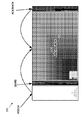
Figure 1 is an illustrative example of a self-contained frame structure;
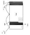
Figures 2 and 3 are illustrative examples of a self-contained frame structure featuring a Channel State Information Feedback Channel (CFCH) , according to some of the example embodiments;
Figure 4 is an illustrative example of aggregated subframes, according to some of the example embodiments;
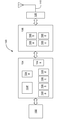
Figures 5 and 6 are example configurations of hardware resources which may be provided in any nodes or logic, according to some of the example embodiments; and
Figure 7 is a flow diagram depicting example operations that can be performed by an electronic device or User Equipment of Figures 5 and 6, according to some of the example embodiments.
In the following description, for the purposes of explanation and not limitation, specific details are set forth, such as particular components, elements, techniques, etc. in order to provide a thorough understanding of the example embodiments. However, the example embodiments may be practiced in other manners that depart from these specific details. In other instances, detailed descriptions of well-known methods and elements are omitted so as not to obscure the description of the example embodiments.
System Overview: In embodiments, this disclosure may relate to LTE Rel-14 and 5G SI. Example embodiments presented herein are directed towards providing Channel State Information (CSI) feedback in a CSI Feedback Channel (CFCH) .
In a 5G system, the massive Multiple Input Multiple Output (MIMO) may be used to enhance the spectrum efficiency and coverage. To support massive MIMO, the User Equipment (UE) may need to report its Channel State Information (CSI) to the eNodeB, which may contain the Beam Index (BI) , Rank Indicator (RI) , Precoding Matrix Indicator (PMI) , Channel Quality Indicator (CQI) and so on. As Transmitting (Tx) beamforming and Receiving (Rx) beamforming may be applied in massive MIMO, the manner of reporting the CSI to the eNodeB with the Tx and Rx beamforming can be an issue.
Further, new frame structure may be used in the 5G system, which could help to achieve low latency and implement flexible duplex operation. An example for the new frame structure is shown in Figure 1, which can be called a self-contained frame structure. In the self-contained frame structure, the data and its corresponding control information (including Downlink Control Information (DCI) and ACK/NACK feedback) can be transmitted in one subframe. Then how to report the CSI in the new frame structure may be an issue.
Fig. 1 illustrates an example of the self-contained frame structure 200. The frame structure 200 may be formatted for either a Physical Downlink Shared Channel (PDSCH) 201 or a Physical Uplink Shared Channel (PUSCH) 202. The frame structure 200 may
have designated resource elements to carrying information. For example a Physical Downlink Control Channel (PDCCH) , a Demodulated Reference Signal (DMRS) , and an Acknowledegement/NonAcknowledgement (ACK/NACK) . The self-contained frame structure is advantageous as it reduces latency.
It should be appreciated that the self-contained frame structure does not comprise a means for reporting CSI feedback data. Typically a UE will send CSI feedback via the PUSCH. However, the PUSCH is not always available nor will the UE always have sufficient resources to send CSI feedback via the PUSCH. With the use of massive MIMO, the number of communications antennas may be very large. Thus, there is an increased need to report CSI feedback, for example, in order to provide beam tracking or beam forming in an efficient manner.
Therefore, the example embodiments provide a means for allowing a UE to send CSI feedback in a reliable manner. Thus, the example embodiments presented herein are directed towards a UE providing CSI feedback via a dedicated CSI Feedback Channel (CFCH) . At least one example advantage of the CFCH is that the UE will be able to provide CSI feedback in a more reliable manner. For example, the UE may provide such feedback in a periodic manner.
Fig. 2 illustrates a self-contained frame structure featuring a dedicated CFCH 203. In the example provided in Fig. 2, the frame structure is formatted for PDSCH. Fig. 3 illustrates another example of a self-contained from structure featuring a dedicated CFCH 203. In the example provided in Fig. 3, the frame structure is formatted for PUSCH.
According to some of the example embodiments, three concepts may be comprised in providing the CFCH. First, CSI sequence channel generated may be provided. Thereafter, Resource mapping for the CFCH may be provided. Finally, downlink control signalling for the CFCH may be established.
The remainder of the text is arranged as follows. First, various example embodiments related to CSI sequence channel generation are discussed under the heading ‘CSI Sequence Generation’ . Thereafter, various example embodiments related to resource allocation is provided under the heading ‘Resource Mapping’ . Various example embodiments directed towards control signalling is provided under the heading ‘Downlink Control Signalling’ . Example configurations of nodes which are operational to perform the example embodiments are provided under the heading ‘Example Configuration’ . Example operational flows of the nodes, according to some of the example embodiments, are provided under the heading ‘Example Operations’ . Finally, various examples of the embodiments presented herein are provided under the heading ‘Working Examples’ .
CSI Sequence Generation: The procedure for the CSI Feedback Channel (CFCH) signal generation may comprise channel coding, scrambling, modulation, layer mapping and precoding and resource mapping. For the channel coding the Cyclic Redundancy Check (CRC) and Tail Biting Conventional Code (TBCC) may be used. The scrambling may be based on cell ID. Quadrature Phase Shift Keying (QPSK) may be applied for modulation. Single layer may be used and the CFCH may be beamforming based. For resource mapping, one UE may occupy one set of subcarriers in the CFCH area independently. An embodiment for the signal generation may comprise channel coding and modulation as follows.
The CSI including BI, RI, PMI and CQI may be the payload for the channel coding with CRC encoding. In one subframe, a UE may need to report the CSI and ACK/NACK to the eNodeB. In this case, the ACK/NACK may be transmitted in the CFCH associated with CSI.
According to some of the example embodiments, CSI feedback follows the CSI-RS transmission without explicit scheduling or triggering. For example, when CSI-RS for CSI-RS group 1 is scheduled/triggered to transmit in current Transmission Time Interval (TTI) , then CSI feedback for UEs within this CSI-RS group are expected to be sent back in the CFCH of the same TTI. Such example embodiments provide an automatic triggering for reporting. For example, reporting may take place in a next available channel. Thus, downlink assignments for the CSI feedback is not needed.
According to some of the example embodiments, for TTI with Physical Downlink Shared Channel (PDSCH) transmission, the CFCH is Time Division Multiplexed (TDMed) with the ACK/NACK symbol. UE will perform downlink PDSCH data decoding process while transmitting the CFCH. In this case, either UE processing requirement can be relaxed, or the Gap can be reduced to include only Tx/Rx switching time and Round Trip Time (RTT) .
According to some of the example embodiments, the analog beamforming weights used to send the CFCH at UE will use the same analog weight used to receive Channel State Information –Reference Signals (CSI-RS) . The analog beamforming weight used to receive the CFCH at eNB, will follow the same beam direction as the CSI-RS transmission. Therefore, the same beamforming weight will be used for the transmission and reception of communications. Thus, the eNodeB will have knowledge of which beamforming weight to use when receiving communications.
According to some of the example embodiments, if the CSI and PDSCH are triggered in one downlink assignment and both are enabled, the payload of the CFCH may comprise CSI and ACK/NACK and the CRC and TBCC may be used to encode the
payload. Alternatively as the requirement for the quality of ACK/NACK is higher than CSI, different channel coding schemes may be used between ACK/NACK and CSI. The ACK/NACK may use a lower coding rate. According to some of the example embodiments, a repetition code may be applied on ACK/NACK bits. Subsequently, the coded ACK/NACK can be aggregated with CSI bit as an input for TBCC coding.
According to some of the example embodiments, if the CSI and PDSCH are triggered in different downlink assignments, the Discontinous Reception (DTX) case may result in payload size mismatch. Then the UE may always keep the ACK/NACK bits area in CSI no matter whether ACK/NACK feedback is needed. In this case, ACK/NACK bits may be set as default, e.g., 0. Thus, the payload size will be matched.
According to some of the example embodiments, the ACK/NACK may be transmitted implicitly in the CRC. There may be totally K types of CRC sequences, where K=2N and N refers to the maximum number of ACK/NACK bits. Then different ACK/NACK bits value may result in different CRC sequences for CSI. If the PDSCH is not scheduled the UE may consider all ACK/NACK bits to be all zeros. Table 1 illustrates one example of CRC sequence for maximum 2 ACK/NACK bits case, where cj indicates the jth CRC sequence.
Table 1: CFCH CRC Sequence for maximum 2 ACK/NACK bits case
| ACK/NACK Bits | CRC Sequence |
| 00 | c0 |
| 01 | c1 |
| 10 | c2 |
| 11 | c3 |
In another embodiment, the ACK/NACK may be transmitted implicitly in the CFCH Reference Signal (RS) . The CFCH RS may be generated as (1) .
s′ (m) =s (m) d (1)
Where s (m) indicates the base sequence for CFCH RS which may be generated based on cell ID; d may be obtained by ACK/NACK bits and an example for 2 bits case is shown in Table 2.
Table 2: CFCH RS factor Indication
| ACK/NACK Bits | d |
| 00 | 1 |
| 01 | -j |
| 10 | j |
| 11 | -1 |
For the downlink data aggregated subframe structure shown in Fig. 4, there may be a large number of ACK/NACK bits to report. According to some of the example embodiments, when transmitting the ACK/NACK associated with the CSI by CFCH as the embodiments above, the ACK/NACK bundling may be used. Then if one of the aggregated subframes has a NACK for one codeword, the NACK may be transmitted for this codeword; otherwise ACK may be transmitted.
Alternatively, multiple CFCH resources may be allocated to one UE, which may be used to carry some information on the ACK/NACK. If the number of aggregated subframes is very large, ACK/NACK multiplexing may be applied. For example, if two aggregated subframes are applied, there may be totally 4 ACK/NACK bits to feedback. The first two ACK/NACK bits may be used to decide the resource index of CFCH, and the last two ACK/NACK bits may be used to decide the CFCH RS as Table 2.
Resource Mapping: There may be S symbols used for CFCH, which may be the same in the network or configured by Radio Resource Control (RRC) signalling or common physical layer control channels. Figs. 2 and 3 shows possible positions for the CFCH. According to some of the example embodiments, for the downlink data subframe, the CFCH may be adjacent to the ACK/NACK channel and for the uplink data subframe, the CFCH may be after the Physical Uplink Shared Channel (PUSCH) .
According to some of the example embodiments, when UE that sends CFCH does not have PUSCH allocation, CFCH may be after the PUSCH transmission using separate symbol. When UE that sends CFCH has PUSCH allocation, the CSI information can be packed into the same MAC Service Data Unit (MSDU) with data transmission, and sent through the PUSCH. No separate CFCH may be needed in this case.
According to some of the example embodiments, the UE may take g subcarriers in the CFCH symbols to report its CSI, where g may be indicated by the Downlink Control Information (DCI) , in which a CFCH aggregation level indicator may be used to indicate the number of g. An example for the CFCH aggregation level indication is shown in Table 3.
Table 3: CFCH Aggregation Level Indication
| CFCH Aggregation Level Bits | g |
| 0 | 36 |
| 1 | 72 |
| 2 | 144 |
| 3 | 288 |
The starting subcarriers for each UE may be configured by RRC signalling or calculated based on a hash function of the Radio Network Temporary Identity (RNTI) . If the number of total CFCH symbol is above 1, the symbol index for the UE’s CFCH may be indicated by RRC signalling or DCI. One UE may take only one symbol for CSI report.
As a further extension, the aggregation level for the CFCH transmission may be fixed. In one example, the system bandwidth can be equally divided into M aggregation levels, or sub-bands, and M may be configured by the network or the RRC signalling. The CFCH for one UE may occupy one sub-band. The sub-band index for the CFCH transmission may be explicitly indicated in the DCI format or provided by higher layer via RRC signalling. Alternatively, the sub-band index for the CFCH transmission may be defined as a function of symbol/slot/subframe/frame index and/or C-RNTI and/or cell ID or virtual cell ID. The CFCH reference signal (RS) may be generated based on cell ID or virtual cell ID, which may be transmitted associated with CFCH with the same Tx beam.
Downlink Control Signalling: For each PUSCH Tx, the UE may need to know whether the symbols reserved for CFCH can be used by PUSCH. According to some of the example embodiments, the CFCH may be periodic, which means if the equation (2) is true the PUSCH may reserve the symbols for CFCH; otherwise no symbols may be reserved for CFCH. For aperiodic CSI feedback, it may be reported by PUSCH. The CFCH period and subframe offset can be configured by RRC signalling.
nsf mod T=Toffset (2)
Where nsf indicates the number of subframe; T denotes the CFCH period; Toffset refers to the subframe offset.
According to some of the example embodiments, one indicator may be added in uplink grant to show whether the CFCH is enabled. If it is enabled the UE may reserve the symbols for CFCH; otherwise the UE may not reserve the symbols for CFCH. Alternatively a common physical layer channel may be used to indicate the number of symbols for CFCH in one subframe.
According to some of the example embodiments, for the UE with CSI reporting and PUSCH resource, it may transmit the CSI by PUSCH instead of CFCH no matter whether the CSI is periodic or aperiodic. If the number of CSI bits is high, the eNodeB may schedule PUSCH to report the CSI.
Example Configuration: As used herein, the term "circuitry" may refer to, be part of, or include an Application Specific Integrated Circuit (ASIC) , an electronic circuit, a processor (shared, dedicated, or group) , and/or memory (shared, dedicated, or group) that execute one or more software or firmware programs, a combinational logic circuit, and/or other suitable hardware components that provide the described functionality. In some embodiments, the circuitry may be implemented in, or functions associated with the circuitry may be implemented by, one or more software or firmware modules. In some embodiments, circuitry may include logic, at least partially operable in hardware.
Embodiments described herein may be implemented into a system using any suitably configured hardware and/or software. Fig. 5 illustrates, for one embodiment, example components of an electronic device 100. In embodiments, the electronic device 100 may be, implement, be incorporated into, or otherwise be a part of user equipment (UE) , an evolved NodeB (eNB) , or other wireless communication equipment. In some embodiments, the electronic device 100 may include application circuitry 102, baseband circuitry 104, Radio Frequency (RF) circuitry 106, front-end module (FEM) circuitry 108 and one or more antennas 110, coupled together at least as shown.
The application circuitry 102 may include one or more application processors. For example, the application circuitry 102 may include circuitry such as, but not limited to, one or more single-core or multi-core processors. The processor (s) may include any combination of general-purpose processors and dedicated processors (e.g., graphics processors, application processors, etc. ) . The processors may be coupled with and/or may include memory/storage and may be configured to execute instructions stored in thememory/storage to enable various applications and/or operating systems to run on the system.
The baseband circuitry 104 may include circuitry such as, but not limited to, one or more single-core or multi-core processors. The baseband circuitry 104 may include one or more baseband processors and/or control logic to process baseband signals received from a receive signal path of the RF circuitry 106 and to generate baseband signals for a transmit signal path of the RF circuitry 106. Baseband processing circuity 104 may interface with the application circuitry 102 for generation and processing of the baseband signals and for controlling operations of the RF circuitry 106. For example, in
some embodiments, the baseband circuitry 104 may include a second generation (2G) baseband processor 104a, third generation (3G) baseband processor 104b, fourth generation (4G) baseband processor 104c, and/or other baseband processor (s) 104d for other existing generations, generations in development or to be developed in the future (e.g., fifth generation (5G) , 6G, etc. ) . The baseband circuitry 104 (e.g., one or more of baseband processors 104a-d) may handle various radio control functions that enable communication with one or more radio networks via the RF circuitry 106. The radio control functions may include, but are not limited to, signal modulation/demodulation, encoding/decoding, radio frequency shifting, etc. In some embodiments, modulation/demodulation circuitry of the baseband circuitry 104 may include Fast-Fourier Transform (FFT) , precoding, and/or constellation mapping/demapping functionality. In some embodiments, encoding/decoding circuitry of the baseband circuitry 104 may include convolution, tail-biting convolution, turbo, Viterbi, and/or Low Density Parity Check (LDPC) encoder/decoder functionality. Embodiments of modulation/demodulation and encoder/decoder functionality are not limited to these examples and may include other suitable functionality in other embodiments.
In some embodiments, the baseband circuitry 104 may include elements of a protocol stack such as, for example, elements of an evolved universal terrestrial radio access network (EUTRAN) protocol including, for example, physical (PHY) , media access control (MAC) , radio link control (RLC) , packet data convergence protocol (PDCP) , and/or radio resource control (RRC) elements. A central processing unit (CPU) 104e of the baseband circuitry 104 may be configured to run elements of the protocol stack for signalling of the PHY, MAC, RLC, PDCP and/or RRC layers. In some embodiments, the baseband circuitry may include one or more audio digital signal processor (s) (DSP) 104f. The audio DSP (s) 104f may be include elements for compression/decompression and echo cancellation and may include other suitable processing elements in other embodiments.
The baseband circuitry 104 may further include memory/storage 104g. The memory/storage 104g may be used to load and store data and/or instructions for operations performed by the processors of the baseband circuitry 104. Memory/storage for one embodiment may include any combination of suitable volatile memory and/or non-volatile memory. The memory/storage 104g may include any combination of various levels of memory/storage including, but not limited to, read-only memory (ROM) having embedded software instructions (e.g., firmware) , random access memory (e.g., dynamic random access memory (DRAM) ) , cache , buffers, etc. The memory/storage 104g may be shared among the various processors or dedicated to particular processors.
Components of the baseband circuitry may be suitably combined in a single chip, a single chipset, or disposed on a same circuit board in some embodiments. In some embodiments, some or all of the constituent components of the baseband circuitry 104 and the application circuitry 102 may be implemented together such as, for example, on a system on a chip (SOC) .
In some embodiments, the baseband circuitry 104 may provide for communication compatible with one or more radio technologies. For example, in some embodiments, the baseband circuitry 104 may support communication with an evolved universal terrestrial radio access network (EUTRAN) and/or other wireless metropolitan area networks (WMAN) , a wireless local area network (WLAN) , a wireless personal area network (WPAN) . Embodiments in which the baseband circuitry 104 is configured to support radio communications of more than one wireless protocol may be referred to as multi-mode baseband circuitry.
In some embodiments, the RF circuitry 106 may include a receive signal path and a transmit signal path. The receive signal path of the RF circuitry 106 may include mixer circuitry 106a, amplifier circuitry 106b and filter circuitry 106c. The transmit signal path of the RF circuitry 106 may include filter circuitry 106c and mixer circuitry 106a. RF circuitry 106 may also include synthesizer circuitry 106d for synthesizing a frequency for use by the mixer circuitry 106a of the receive signal path and the transmit signal path. In some embodiments, the mixer circuitry 106a of the receive signal path may be configured to down-convert RF signals received from the FEM circuitry 108 based on the synthesized frequency provided by synthesizer circuitry 106d. The amplifier circuitry 106b may be configured to amplify the down-converted signals and the filter circuitry 106c may be a low-pass filter (LPF) or band-pass filter (BPF) configured to remove unwanted signals from the down-converted signals to generate output baseband signals. Output baseband signals may be provided to the baseband circuitry 104 for further processing. In some embodiments, the output baseband signals may be zero-frequency baseband signals,
although this is not a requirement. In some embodiments, mixer circuitry 106a of the receive signal path may comprise passive mixers, although the scope of the embodiments is not limited in this respect.
In some embodiments, the mixer circuitry 106a of the transmit signal path may be configured to up-convert input baseband signals based on the synthesized frequency provided by the synthesizer circuitry 106d to generate RF output signals for the FEM circuitry 108. The baseband signals may be provided by the baseband circuitry 104 and may be filtered by filter circuitry 106c. The filter circuitry 106c may include a low-pass filter (LPF) , although the scope of the embodiments is not limited in this respect.
In some embodiments, the mixer circuitry 106a of the receive signal path and the mixer circuitry 106a of the transmit signal path may include two or more mixers and may be arranged for quadrature downconversion and/or upconversion respectively. In some embodiments, the mixer circuitry 106a of the receive signal path and the mixer circuitry 106a of the transmit signal path may include two or more mixers and may be arranged for image rejection (e.g., Hartley image rejection) . In some embodiments, the mixer circuitry 106a of the receive signal path and the mixer circuitry 106a may be arranged for direct downconversion and/or direct upconversion, respectively. In some embodiments, the mixer circuitry 106a of the receive signal path and the mixer circuitry 106a of the transmit signal path may be configured for super-heterodyne operation.
In some embodiments, the output baseband signals and the input baseband signals may be analog baseband signals, although the scope of the embodiments is not limited in this respect. In some alternate embodiments, the output baseband signals and the input baseband signals may be digital baseband signals. In these alternate embodiments, the RF circuitry 106 may include analog-to-digital converter (ADC) and digital-to-analog converter (DAC) circuitry and the baseband circuitry 104 may include a digital baseband interface to communicate with the RF circuitry 106.
In some dual-mode embodiments, a separate radio IC circuitry may be provided for processing signals for each spectrum, although the scope of the embodiments is not limited in this respect.
In some embodiments, the synthesizer circuitry 106d may be a fractional-N synthesizer or a fractional N/N+1 synthesizer, although the scope of the embodiments is not limited in this respect as other types of frequency synthesizers may be suitable. For example, synthesizer circuitry 106d may be a delta-sigma synthesizer, a frequency multiplier, or a synthesizer comprising a phase-locked loop with a frequency divider.
The synthesizer circuitry 106d may be configured to synthesize an output frequency for use by the mixer circuitry 106a of the RF circuitry 106 based on a frequency input and a divider control input. In some embodiments, the synthesizer circuitry 106d may be a fractional N/N+1 synthesizer.
In some embodiments, frequency input may be provided by a voltage controlled oscillator (VCO) , although that is not a requirement. Divider control input may be provided by either the baseband circuitry 104 or the applications processor 102 depending on the desired output frequency. In some embodiments, a divider control input (e.g., N) may be determined from a look-up table based on a channel indicated by the applications processor 102.
Synthesizer circuitry 106d of the RF circuitry 106 may include a divider, a delay-locked loop (DLL) , a multiplexer and a phase accumulator. In some embodiments, the divider may be a dual modulus divider (DMD) and the phase accumulator may be a digital phase accumulator (DPA) . In some embodiments, the DMD may be configured to divide the input signal by either N or N+1 (e.g., based on a carry out) to provide a fractional division ratio. In some example embodiments, the DLL may include a set of cascaded, tunable, delay elements, a phase detector, a charge pump and a D-type flip-flop. In these embodiments, the delay elements may be configured to break a VCO period up into Nd equal packets of phase, where Nd is the number of delay elements in the delay line. In this way, the DLL provides negative feedback to help ensure that the total delay through the delay line is one VCO cycle.
In some embodiments, synthesizer circuitry 106d may be configured to generate a carrier frequency as the output frequency, while in other embodiments, the output frequency may be a multiple of the carrier frequency (e.g., twice the carrier frequency, four times the carrier frequency) and used in conjunction with quadrature generator and divider circuitry to generate multiple signals at the carrier frequency with multiple different phases with respect to each other. In some embodiments, the output frequency may be a LO frequency (fLO) . In some embodiments, the RF circuitry 106 may include an IQ/polar converter.
In some embodiments, the FEM circuitry 108 may include a TX/RX switch to switch between transmit mode and receive mode operation. The FEM circuitry may include a receive signal path and a transmit signal path. The receive signal path of the FEM circuitry may include a low-noise amplifier (LNA) to amplify received RF signals and provide the amplified received RF signals as an output (e.g., to the RF circuitry 106) . The transmit signal path of the FEM circuitry 108 may include a power amplifier (PA) to amplify input RF signals (e.g., provided by RF circuitry 106) , and one or more filters to generate RF signals for subsequent transmission (e.g., by one or more of the one or more antennas 110.
In some embodiments, the electronic device 100 may include additional elements such as, for example, memory/storage, display, camera, sensor, and/or input/output (I/O) interface.
In embodiments where the electronic device 100 is, implements, is incorporated into, or is otherwise part of a UE (or a portion thereof) , the baseband circuitry 104 may be to generate a CSI sequence and provide resource mapping for a CSI feedback channel. The RF circuitry 106 may be to report a UE measured CSI.
Fig. 6 is a block diagram illustrating components, according to some example embodiments, able to read instructions from a machine-readable or computer-readable medium (e.g., a machine-readable storage medium) and perform any one or more of the methodologies discussed herein. Specifically, FIG. 6 shows a diagrammatic representation of hardware resources 600 including one or more processors (or processor cores) 610, one or more memory/storage devices 620, and one or more communication resources 630, each of which are communicatively coupled via a bus 640.
The processors 610 (e.g., a central processing unit (CPU) , a reduced instruction set computing (RISC) processor, a complex instruction set computing (CISC) processor, a graphics processing unit (GPU) , a digital signal processor (DSP) such as a baseband processor, an application specific integrated circuit (ASIC) , a radio-frequency integrated circuit (RFIC) , another processor, or any suitable combination thereof) may include, for example, a processor 612 and a processor 614. The memory/storage devices 620 may include main memory, disk storage, or any suitable combination thereof.
The communication resources 630 may include interconnection and/or network interface components or other suitable devices to communicate with one or more peripheral devices 604 and/or one or more databases 606 via a network 608. For example, the communication resources 630 may include wired communication components (e.g., for coupling via a Universal Serial Bus (USB) ) , cellular communication components, Near
Field Communication (NFC) components,  components (e.g.,
  Low Energy) ,
  components, and other communication components.
Example Operations: Fig. 7 is a flow diagram depicting example operations which may be taken by the electronic device or apparatus 100 of Figs. 5 and 6, in providing CSI feedback in a CSI Feedback Channel (CFCH) comprised in a self-contained frame structure. It should be appreciated that the operations of Fig. 7 need not be performed in order. Furthermore, it should be appreciated that not all of the operations need to be performed. The example operations may be performed in any order and in any combination.
The apparatus 100 generates 10 a CSI sequence for a payload of the CFCH. The processing or application circuitry generates the CSI sequence for the payload of the CFCH. Operation 10 is further described under at least the heading ‘CSI Sequence Generation’ .
According to some of the example embodiments, the apparatus 100, or processing or application circuitry, provides a value of the CSI sequence in the form of an ACK/NACK represented via a transmitted CRC sequence. According to some of the example embodiments, the CSI sequence, in the form of an ACK/NACK is multiplexed within a plurality of subframes. According to some of the example embodiments, the apparatus, or processing or application circuitry, is further configured to aggregate the ACK/NACK with the CSI feedback.
The apparatus 100 also maps 12 resources for uplink data transmission in the CFCH. The processing circuitry maps resources for uplink data transmission in the CFCH. Operation 12 is further described under at least the heading ‘Resource Mapping’ .
According to some of the example embodiments, the self-contained frame structure comprises a Physical Uplink Shared Channel (PUSCH) and the processing circuitry maps the resources within the PUSCH in an available uplink symbol or within the payload of the CFCH. According to some of the example embodiments, the processing circuitry maps the resources in the CFCH, where the CFCH is after the PUSCH. According to some of the example embodiments, the processing circuitry maps the resources in the CFCH via a placement of CSI feedback in a same Medium access control Service Data Unit (MSDU) with data transmission.
According to some of the example embodiments, the self-contained frame structure comprises a Physical Downlink Shared Channel (PDSCH) . The PDSCH and CSI feedback are triggered in one downlink assignment. The processing circuitry maps resources in the payload of the CFCH, where the CSI sequence in the payload comprises the CSI feedback and an Acknowledgement/Negative Acknowledgement (ACK/NACK) .
According to some of the example embodiments, the self-contained frame structure comprises a plurality of aggregated subframes.
According to some of the example embodiments, the processing circuitry receives Downlink Control Information (DCI) , The DCI comprises a CFCH aggregation level indicator. The processing circuitry determines a number of subcarriers in the CFCH symbols to report the CSI feedback based on the received CFCH aggregation level.
The apparatus reports 14, to a base station, the CSI feedback in the CFCH, comprising the generated CSI sequence, according to the mapped resources. The processing or radio frequency circuitry reports, to the base station the CSI feedback in the CFCH, comprising the generated CSI sequence, according to the mapped resources. Operation 14 is further described under at least the heading ‘Downlink Control Signalling’ .
According to some of the example embodiments, the processing circuitry receives an uplink grant. If the uplink grant indicates the CFCH is enabled, the application circuitry reserves symbols in the self-contained frame structure for the CFCH.
According to some of the example embodiments, the self-contained frame structure comprises a PUSCH and the processing circuitry reserves symbols in the PUSCH for the CFCH.
According to some of the example embodiments, the processing circuity reserves the symbols in the PUSCH for the CFCH. The reserving is performed if a defined condition is satisfied. According to some of the example embodiments, such a condition may be nsf modT=Toffset, wherein nsf indicates a number of a subframe in the self-contained frame structure, T indicates the CFCH period and Toffset indicates a subframe offset.
According to some of the example embodiments, the processing circuitry reports CSI feedback in a same Transmission Time Interval (TTI) in which a CSI-Reference Signal (CSI-RS) is received.
Working Examples: Example 1 may include a method, which includes configuring a Channel State Information (CSI) Feedback Channel (CFCH) and reporting a UE measured CSI.
In Example 2, the subject matter of Example 1 or any of the Examples or clauses described herein may further include the number of symbols for CFCH may be configured by network or Radio Resource Control (RRC) signalling.
In Example 3, which may include the method of Example 1 and/or any other Example or clauses described herein, wherein the UE may transmit its CSI and ACK/NACK by CFCH if it is not granted PUSCH resource for current subframe; otherwise the UE may transmit the CSI via PUSCH by using a MAC Service Data Unit (SDU) .
Example 4, which may include the method of Example 3 and/or any other Example or clauses described, wherein the ACK/NACK and CSI may use the same channel coding scheme.
Example 5, which may include the method of Example 3 and/or any other Example or clauses described, wherein no matter whether the UE needs to report the ACK/NACK, the corresponding bits may need to be reserved to the ACK/NACK.
Example 6, which may include the method of Example 3 and/or any other Example or clauses described, wherein the CFCH may use several Cyclic Redundant Check (CRC) codes and the index for the CRC code may be decided by the value of the ACK/NACK.
Example 7, which may include the method of Example 3 and/or any other Example or clauses described, wherein the Reference Signal (RS) for CFCH may be generated based on cell ID or virtual cell ID and the ACK/NACK bits.
Example 8, which may include the method of Example 1 and/or any other Example or clauses described, wherein the CFCH symbols may be before the ACK/NACK symbols in the downlink data subframe and after the PUSCH symbols in the uplink data subframe.
Example 9, which may include the method of Example 8 and/or any other Example or clauses described, wherein the UE may transmit its CFCH in the subcarriers in the CFCH symbols.
Example 10, which may include the method of Example 9 and/or any other Example or clauses described, wherein the starting index for each UE’s subcarrier may be configured by the RRC signalling or calculated by a function of UE’s Radio Network Temporary Identity (RNTI) .
Example 11, which may include the method of Example 9 and/or any other Example or clauses described, wherein the aggregation level of the subcarriers may be configured by the network, RRC signalling or Downlink Control Information (DCI) .
Example 12, which may include the method of Example 1 and/or any other Example or clauses described, wherein the CFCH may be enabled periodically and the period and subframe offset may be configured by the network or RRC signalling.
Example 13 may include a Channel State Information (CSI) feedback method including generating a CSI sequence, identifying a mapping of a resource for a CSI feedback channel (CFCH) , and reporting a UE measured CSI.
Example 14, which may include the method of Example 13 and/or any other Example or clauses described, and further includes signalling a downlink control for the CSI feedback channel.
Example 15, which may include the method of Example 13 and/or any other Example or clauses described, wherein the number of symbols for CFCH may be configured by network or Radio Resource Control (RRC) signalling.
Example 16, which may include the method of Example 13 and/or any other Example or clauses described, wherein the UE may transmit its CSI and ACK/NACK by CFCH if it is not granted PUSCH resource for current subframe; otherwise the UE may transmit the CSI via PUSCH by using a MAC Service Data Unit (SDU) .
Example 17, which may include the method of Example 16 and/or any other Example or clauses described, wherein the ACK/NACK and CSI may use the same channel coding scheme.
Example 18, which may include the method of Example 16 and/or any otherExample or clauses described, wherein no matter whether the UE needs to report the ACK/NACK, the corresponding bits may need to be reserved to the ACK/NACK.
Example 19, which may include the method of Example 16 and/or any other Example or clauses described, wherein the CFCH may use several Cyclic Redundant Check (CRC) codes and the index for the CRC code may be decided by the value of the ACK/NACK.
Example 20, which may include the method of Example 16 and/or any other Example or clauses described, wherein the Reference Signal (RS) for CFCH may be generated based on cell ID or virtual cell ID and the ACK/NACK bits.
Example 21, which may include the method of Example 13 and/or any other Example or clauses described, wherein the CFCH symbols may be before the ACK/NACK symbols in the downlink data subframe and after the PUSCH symbols in the uplink data subframe.
Example 22, which may include the method of Example 21 and/or any other Example or clauses described, wherein the UE may transmit its CFCH in the subcarriers in the CFCH symbols.
Example 23, which may include the method of Example 22 and/or any other Example or clauses described, wherein the starting index for each UE’s subcarrier may be configured by the RRC signalling or calculated by a function of UE’s Radio Network Temporary Identity (RNTI) .
Example 24, which may include the method of Example 22 and/or any other Example or clauses described, wherein the aggregation level of the subcarriers may be configured by the network, RRC signalling or Downlink Control Information (DCI) .
Example 25, which may include the method of Example 13 and/or any other Example or clauses described, wherein the CFCH may be enabled periodically and the period and subframe offset may be configured by the network or RRC signalling.
Example 26 may include an electronic device comprising: baseband circuitry to generate a CSI sequence and provide resource mapping for a CSI feedback channel; and radio frequency (RF) circuitry coupled with the baseband circuitry, the RF circuitry to report a UE measured CSI.
Example 27 may include an apparatus comprising means to perform one or more elements of a method described in or related to any of Examples 1-25, or any other method or process or clauses described herein.
Example 28 may include one or more non-transitory computer-readable media comprising instructions to cause an electronic device, upon execution of the instructions by one or more processors of the electronic device, to perform one or more elements of a method described in or related to any of Examples 1-25, or any other method or process or clauses described herein.
Example 29 may include an apparatus comprising logic, modules, and/or circuitry to perform one or more elements of a method described in or related to any of Examples 1-25, or any other method or process or clauses described herein.
Example 30 may include an apparatus comprising: one or more processors and one or more computer readable media comprising instructions that, when executed by the one or more processors, cause the one or more processors to perform the method, techniques, or process as described in or related to any of Examples 1-25, or portions thereof.
Example 31 may include a method of communicating in a wireless network as shown and described herein and in any of Examples 1-25.
Example 32 may include a system for providing wireless communication as shown and described herein.
Example 33 may include a device for providing wireless communication as shown and described herein.
Example 34 may include the method of any of claims 1-25, wherein the method is performed by a user equipment (UE) or a portion thereof.
Further example embodiments are provided according to the following numbered clauses:
Clause 1: An apparatus, for use in a User Equipment (UE) for providing Channel State Information (CSI) feedback in a CSI Feedback Channel (CFCH) , comprised in a self-contained frame structure. The apparatus comprises processing circuitry to generate a CSI sequence for a payload of the CFCH. The processing circuitry further to map resources for uplink data transmission in the CFCH. According to some of the example embodiments, application circuitry may perform the generating and mapping. The apparatus further comprises processing circuitry to report, to a base station, the CSI feedback in the CFCH
within the self-contained fame structure, comprising the generated CSI sequence, according to the mapped resources. According to some of the example embodiments, radio frequency circuitry may perform the reporting.
Clause 2: The apparatus of clause 1 and any other examples or clauses described, wherein the processing is to receive an uplink grant, if said uplink grant indicates the CFCH is enabled, the processing circuitry to reserve symbols in the self-contained frame structure for the CFCH.
Clause 3: The apparatus of any of clauses 1-2 or any other examples or clauses described, wherein the self-contained frame structure comprises a Physical Uplink Shared Channel (PUSCH) and the processing circuitry is further to reserve symbols in the PUSCH for the CFCH.
Clause 4: The apparatus of clause 3 or any other examples or clauses described, wherein the processing circuitry is to reserve the symbols in the PUSCH for the CFCH if the following condition is satisfied: nsf mod T=Toffset, wherein nsf indicates a number of a subframe in the self-contained frame structure, T indicates the CFCH period and Toffset indicates a subframe offset.
Clause 5: The apparatus of any of clauses 1-4 or any other examples or clauses described, wherein the self-contained frame structure comprises a Physical Uplink Shared Channel, PUSCH, and the processing circuitry is further to map the resources within the PUSCH in an available uplink symbol or within the payload of the CFCH.
Clause 6: The apparatus of any of clauses 1-2 or any other examples or clauses described, wherein the self-contained frame structure comprises a Physical Downlink Shared Channel (PDSCH) and wherein the PDSCH and CSI feedback are triggered in one downlink assignment, the processing circuitry is further to map the resources in the payload of the CFCH, wherein the CSI sequence in the payload comprises the CSI feedback and an Acknowledgement /Negative Acknowledgement (ACK/NACK) .
Clause 7: The apparatus of clause 6 or any other examples or clauses described, wherein the processing circuitry is to further aggregate the ACK/NACK with the CSI feedback.
Clause 8: The apparatus of any of clauses 1-7 or any other examples or clauses described, wherein the processing circuitry to provide a value of the CSI sequence in the form of an Acknowledgement /Negative Acknowledgement (ACK/NACK) represented via a transmitted Cyclic Redundancy Check, CRC, sequence.
Clause 9: The apparatus of any of clauses 1-5 and 8 or any other examples or clauses described, wherein the processing circuitry to map the resources in the CFCH, said CFCH being after a Physical Uplink Shared Channel (PUSCH) .
Clause 10: The apparatus of any of clauses 1-5 and 8 or any other examples or clauses described, wherein the self-contained frame structure comprises a Physical Uplink Shared Channel (PUSCH) and the processing circuitry to map the resources in the CFCH, via a placement of CSI feedback in a same Medium access control Service Data Unit (MSDU) with data transmission.
Clause 11: The apparatus of any of clauses 1-10 or any other examples or clauses described, wherein the self-contained frame structure comprises a plurality of aggregated subframes.
Clause 12: The apparatus of clause 11 or any other examples or clauses described, wherein the processing circuitry is configured to receive a Downlink Control Information (DCI) , said DCI comprising CFCH aggregation level indicator, and the processing circuitry to determine a number of subcarriers in the CFCH symbols to report the CSI Feedback based on the received CFCH aggregation level.
Clause 13: The apparatus of any of clauses 11-12 or any other examples or clauses described, wherein the CSI sequence in the form of an Acknowledgement /Negative Acknowledgement (ACK/NACK) is multiplexed within the plurality of aggregated subframes.
Clause 14: The apparatus of any of clauses 1-13 or any other examples or clauses described, wherein the processing circuitry to report the CSI feedback in a same Transmission Time Internal (TTI) in which a CSI-Reference Signal (CSI-RS) is received.
Clause 15: A computer-readable storing machine comprising executable instructions such that when executed by a User Equipment (UE) , cause the UE to provide Channel State Information (CSI) feedback in a CSI Feedback Channel (CFCH) , comprised in a self-contained frame structure. The instructions comprise generating a CSI sequence for a payload of the CFCH, and mapping resources for uplink data transmission in the CFCH. The instructions further comprise reporting, to a base station, the CSI feedback in the CFCH within the self-contained frame structure, comprising the CSI sequence, according to the mapped resources.
Clause 16: The computer-readable storing machine of clause 15 or any other examples or clauses described, wherein the self-contained frame structure comprises a Physical Downlink Shared Channel (PDSCH) and wherein the PDSCH and CSI feedback are triggered in one downlink assignment, the processing circuitry is further to map the
resources in the payload of the CFCH, wherein the CSI sequence in the payload comprises the CSI feedback and an Acknowledgement /Negative Acknowledgement (ACK/NACK) .
Clause 17: A User Equipment (UE) for providing Channel State Information (CSI) feedback in a CSI Feedback Channel (CFCH) , comprised in a self-contained frame structure, the UE for use in a wireless communication network. The UE comprises processing circuitry to generate a CSI sequence for a payload of the CFCH. The processing circuitry further to map resources for uplink data transmission in the CFCH. The UE further comprises radio frequency circuitry to report, to a base station, the CSI feedback in the CFCH within the self-contained frame structure, comprising the generated CSI sequence, according to the mapped resources.
Clause 18: The User Equipment of clause 17 or any other examples or clauses described, wherein the self-contained frame structure comprises a Physical Downlink Shared Channel (PDSCH) and wherein the PDSCH and CSI feedback are triggered in one downlink assignment, the processing circuitry is further to map the resources in the payload of the CFCH, wherein the CSI sequence in the payload comprises the CSI feedback and an Acknowledgement /Negative Acknowledgement (ACK/NACK) .
Clause 19: A method in an apparatus, for use in a User Equipment (UE) for providing Channel State Information (CSI) feedback in a CSI Feedback Channel (CFCH) , comprised in a self-contained frame structure. The method comprises generating a CSI sequence for a payload of the CFCH. The method also comprises mapping resources for uplink data transmission in the CFCH. The method further comprises reporting, to a base station, the CSI feedback in the CFCH within the self-contained frame structure, comprising the generated CSI sequence, according to the mapped resources.
Clause 20: The method of clause 19 or any other examples or clauses described, further comprising receiving an uplink grant, if said uplink grant indicates the CFCH is enabled, reserving symbols in the self-contained frame structure for the CFCH.
Clause 21: A User Equipment (UE) comprising the apparatus of any of clauses 1-14 or any other examples or clauses described.
Clause 22: An apparatus, for use in a User Equipment (UE) for providing Channel State Information (CSI) feedback in a CSI Feedback Channel (CFCH) , comprised in a self-contained frame structure. The apparatus comprises means for generating a CSI sequence for a payload of the CFCH. The apparatus further comprises means for mapping resources for uplink data transmission in the CFCH. The apparatus also comprises means for reporting, to a base station, the CSI feedback in the CFCH within the self-contained
frame structure, comprising the generated CSI sequence, according to the mapped resources.
Clause 23: The apparatus of clause 22 or any other examples or clauses described, further comprising means for receiving an uplink grant, if said uplink grant indicates the CFCH is enabled, the means for mapping to reserve symbols in the self-contained frame structure for the CFCH.
Concluding Remarks: Throughout the description and claims of this specification, the words “comprise” and “contain” and variations of them mean “including but not limited to” , and they are not intended to (and do not) exclude other moieties, additives, components, integers or steps. Throughout the description and claims of this specification, the singular encompasses the plural unless the context otherwise requires. In particular, where the indefinite article is used, the specification is to be understood as contemplating plurality as well as singularity, unless the context requires otherwise.
Features, integers, characteristics, compounds, chemical moieties or groups described in conjunction with a particular aspect, embodiment or example of the example embodiments are to be understood to be applicable to any other aspect, embodiment or example described herein unless incompatible therewith. All of the features disclosed in this specification (including any accompanying claims, abstract and drawings) , and/or all of the steps of any method or process so disclosed, may be combined in any combination, except combinations where at least some of such features and/or steps are mutually exclusive. The example embodiments are not restricted to the details of any foregoing embodiments. The example embodiments extend to any novel one, or any novel combination, of the features disclosed in this specification (including any accompanying claims, abstract and drawings) , or to any novel one, or any novel combination, of the steps of any method or process so disclosed.
The reader's attention is directed to all papers and documents which are filed concurrently with or previous to this specification in connection with this application and which are open to public inspection with this specification, and the contents of all such papers and documents are incorporated herein by reference.
Claims (18)
- An apparatus, for use in a User Equipment, UE, for providing Channel State Information, CSI, feedback in a CSI Feedback Channel, CFCH, comprised in a self-contained frame structure, the apparatus comprising:processing circuitry to:generate a CSI sequence for a payload of the CFCH;map resources for uplink data transmission in the CFCH; andreport, to a base station, the CSI feedback in the CFCH within the self-contained frame structure, comprising the generated CSI sequence, according to the mapped resources.
- The apparatus of claim 1, wherein the processing circuitry is to receive an uplink grant, if said uplink grant indicates the CFCH is enabled, the processing circuitry to reserve symbols in the self-contained frame structure for the CFCH.
- The apparatus of any of claims 1-2, wherein the self-contained frame structure comprises a Physical Uplink Shared Channel, PUSCH, and the processing circuitry is further to reserve symbols in the PUSCH for the CFCH.
- The apparatus of claim 3, wherein the processing circuitry is to reserve the symbols in the PUSCH for the CFCH if the following condition is satisfied: nsf mod T=Toffset, wherein nsf indicates a number of a subframe in the self-contained frame structure, T indicates the CFCH period and Toffset indicates a subframe offset.
- The apparatus of any of claims 1-4, wherein the self-contained frame structure comprises a Physical Uplink Shared Channel, PUSCH, and the processing circuitry is further to map the resources within the PUSCH in an available uplink symbol or within the payload of the CFCH.
- The apparatus of any of claims 1-2, wherein the self-contained frame structure comprises a Physical Downlink Shared Channel, PDSCH, and wherein the PDSCH and CSI feedback are triggered in one downlink assignment, the processing circuitry is further to map the resources in the payload of the CFCH, wherein the CSI sequence in the payload comprises the CSI feedback and an Acknowledgement, ACK, /Negative ACK, NACK.
- The apparatus of claim 6, wherein the processing circuitry is to further aggregate the ACK/NACK with the CSI feedback.
- The apparatus of any of claims 1-7, wherein the processing circuitry to provide a value of the CSI sequence in the form of an Acknowledgement, ACK, /Negative ACK, NACK represented via a transmitted Cyclic Redundancy Check, CRC, sequence.
- The apparatus of any of claims 1-5 and 8, wherein the processing circuitry to map the resources in the CFCH, said CFCH being after a Physical Uplink Shared Channel, PUSCH.
- The apparatus of any of claims 1-5 and 8, wherein the self-contained frame structure comprises a Physical Uplink Shared Channel, PUSCH, and the processing circuitry to map the resources in the CFCH, via a placement of CSI feedback in a same Medium access control Service Data Unit, MSDU, with data transmission.
- The apparatus of any of claims 1-10, wherein the self-contained frame structure comprises a plurality of aggregated subframes.
- The apparatus of claim 11, whereinthe processing circuitry is configured to receive a Downlink Control Information, DCI, said DCI comprising CFCH aggregation level indicator; andthe processing circuitry to determine a number of subcarriers in the CFCH symbols to report the CSI Feedback based on the received CFCH aggregation level.
- The apparatus of any of claims 11-12, wherein the CSI sequence in the form of an Acknowledgement, ACK, /Negative ACK, NACK, is multiplexed within the plurality of aggregated subframes.
- The apparatus of any of claims 1-13, wherein the processing circuitry to report the CSI feedback in a same Transmission Time Internal, TTI, in which a CSI-Reference Signal, RS, is received.
- A computer-readable storing machine comprising executable instructions such that when executed by a User Equipment, UE, cause the UE to provide Channel State Information, CSI, feedback in a CSI Feedback Channel, CFCH, comprised in a self-contained frame structure, the instructions comprising:generating a CSI sequence for a payload of the CFCH;mapping resources for uplink data transmission in the CFCH; andreporting, to a base station, the CSI feedback in the CFCH within the self-contained frame structure, comprising the CSI sequence, according to the mapped resources.
- The computer-readable storing machine of claim 15, wherein the self-contained frame structure comprises a Physical Downlink Shared Channel, PDSCH, and wherein the PDSCH and CSI feedback are triggered in one downlink assignment, the application circuitry is further to map the resources in the payload of the CFCH, wherein the CSI sequence in the payload comprises the CSI feedback and an Acknowledgement, ACK, /Negative ACK, NACK.
- A User Equipment, UE, for providing Channel State Information, CSI, feedback in a CSI Feedback Channel, CFCH, comprised in a self-contained frame structure, the UE for use in a wireless communication network, the UE comprising:processing circuitry to generate a CSI sequence for a payload of the CFCH;the processing circuitry further to map resources for uplink data transmission in the CFCH; andradio frequency circuitry to report, to a base station, the CSI feedback in the CFCH, comprising the generated CSI sequence, according to the mapped resources.
- The User Equipment of claim 17, wherein the self-contained frame structure comprises a Physical Downlink Shared Channel, PDSCH, and wherein the PDSCH and CSI feedback are triggered in one downlink assignment, the application circuitry is further to map the resources in the payload of the CFCH, wherein the CSI sequence in the payload comprises the CSI feedback and an Acknowledgement, ACK, /Negative ACK, NACK.
Priority Applications (1)
| Application Number | Priority Date | Filing Date | Title |
|---|---|---|---|
| TW105128501A TWI703831B (en) | 2015-10-15 | 2016-09-02 | Channel state information feedback channel |
Applications Claiming Priority (2)
| Application Number | Priority Date | Filing Date | Title |
|---|---|---|---|
| US201562242245P | 2015-10-15 | 2015-10-15 | |
| US62/242,245 | 2015-10-15 |
Publications (1)
| Publication Number | Publication Date |
|---|---|
| WO2017063345A1 true WO2017063345A1 (en) | 2017-04-20 |
Family
ID=58517006
Family Applications (1)
| Application Number | Title | Priority Date | Filing Date |
|---|---|---|---|
| PCT/CN2016/078442 WO2017063345A1 (en) | 2015-10-15 | 2016-04-05 | Channel state information feedback channel |
Country Status (2)
| Country | Link |
|---|---|
| TW (1) | TWI703831B (en) |
| WO (1) | WO2017063345A1 (en) |
Cited By (2)
| Publication number | Priority date | Publication date | Assignee | Title |
|---|---|---|---|---|
| GB2560760A (en) * | 2017-03-24 | 2018-09-26 | Tcl Communication Ltd | Methods and devices for controlling a radio access network |
| WO2019068211A1 (en) * | 2017-10-02 | 2019-04-11 | Qualcomm Incorporated | Single packet encoded channel state information (csi) design for new radio (nr) multiple input-multiple output (mimo) |
Citations (5)
| Publication number | Priority date | Publication date | Assignee | Title |
|---|---|---|---|---|
| CN101877884A (en) * | 2009-04-30 | 2010-11-03 | 华为技术有限公司 | Information transmission method and communication device |
| CN102291199A (en) * | 2010-06-18 | 2011-12-21 | 电信科学技术研究院 | Method and device for reporting channel state information |
| CN102437901A (en) * | 2011-12-31 | 2012-05-02 | 电信科学技术研究院 | Combined feedback method and device of uplink control information |
| WO2012068880A1 (en) * | 2010-11-25 | 2012-05-31 | 中兴通讯股份有限公司 | Method and device for feeding back channel state information |
| EP2566085A1 (en) * | 2010-04-30 | 2013-03-06 | ZTE Corporation | Method and terminal for feeding back channel state information |
Family Cites Families (1)
| Publication number | Priority date | Publication date | Assignee | Title |
|---|---|---|---|---|
| CN103825664B (en) * | 2014-02-21 | 2016-05-18 | 电信科学技术研究院 | Channel condition information measuring method and device and method for transmitting signals and device |
-
2016
- 2016-04-05 WO PCT/CN2016/078442 patent/WO2017063345A1/en active Application Filing
- 2016-09-02 TW TW105128501A patent/TWI703831B/en active
Patent Citations (5)
| Publication number | Priority date | Publication date | Assignee | Title |
|---|---|---|---|---|
| CN101877884A (en) * | 2009-04-30 | 2010-11-03 | 华为技术有限公司 | Information transmission method and communication device |
| EP2566085A1 (en) * | 2010-04-30 | 2013-03-06 | ZTE Corporation | Method and terminal for feeding back channel state information |
| CN102291199A (en) * | 2010-06-18 | 2011-12-21 | 电信科学技术研究院 | Method and device for reporting channel state information |
| WO2012068880A1 (en) * | 2010-11-25 | 2012-05-31 | 中兴通讯股份有限公司 | Method and device for feeding back channel state information |
| CN102437901A (en) * | 2011-12-31 | 2012-05-02 | 电信科学技术研究院 | Combined feedback method and device of uplink control information |
Cited By (3)
| Publication number | Priority date | Publication date | Assignee | Title |
|---|---|---|---|---|
| GB2560760A (en) * | 2017-03-24 | 2018-09-26 | Tcl Communication Ltd | Methods and devices for controlling a radio access network |
| WO2019068211A1 (en) * | 2017-10-02 | 2019-04-11 | Qualcomm Incorporated | Single packet encoded channel state information (csi) design for new radio (nr) multiple input-multiple output (mimo) |
| US11258568B2 (en) | 2017-10-02 | 2022-02-22 | Qualcomm Incorporated | Single packet encoded channel state information (CSI) design for new radio (NR) multiple input-multiple output (MIMO) |
Also Published As
| Publication number | Publication date |
|---|---|
| TWI703831B (en) | 2020-09-01 |
| TW201724786A (en) | 2017-07-01 |
Similar Documents
| Publication | Publication Date | Title |
|---|---|---|
| US20200252157A1 (en) | Grant-less pusch uplink | |
| US11245480B2 (en) | Devices and methods for robust measurement and data receiving | |
| US20200403754A1 (en) | UCI for Carrier Aggregation | |
| US11122580B2 (en) | Evolved node-b (ENB), user equipment (UE) and methods for flexible duplex communication | |
| TWI703885B (en) | Dynamic resource allocations and transmission schemes for xpucch (5g pucch) | |
| US10560174B2 (en) | Latency reduction for wireless data transmission | |
| US10779360B2 (en) | Control signaling for fifth generation channel state information reference signals (xCSI-RS) | |
| US20180220407A1 (en) | Indication of tdd uplink and downlink configurations | |
| TWI726991B (en) | Full duplex support in fifth generation (5g) systems | |
| WO2017171956A1 (en) | Uplink modulation coding scheme and configuration | |
| WO2017142581A1 (en) | Multiplexing uplink control information and data on physical uplink shared channel | |
| WO2016122756A1 (en) | Device and method for effective use of unlicensed spectrum | |
| CN108781124B (en) | Apparatus and operation method for user equipment, apparatus and medium for base station | |
| US10396878B2 (en) | Channel coding and interleaving for control and user data in the physical uplink shared channel | |
| WO2017142574A1 (en) | FIFTH GENERATION (5G) UPLINK CONTROL INFORMATION (xUCI) REPORT | |
| WO2017136706A1 (en) | Multi-shot aperiodic channel state information report for full dimension-multiple input multiple output systems | |
| WO2018038758A1 (en) | Transmission of control information after uplink grant | |
| US20200313785A1 (en) | Enhanced overlaid code division multiple access (cdma) | |
| WO2016164074A1 (en) | Device and method of supporting 4 layer transmission with 256 quadrature amplitude modulation | |
| CN109314872B (en) | Apparatus and computer readable storage medium in wireless communication network | |
| WO2018004631A1 (en) | Method for crc ambiguity avoidance in 5g dci decoding | |
| WO2017146756A1 (en) | Uci channel coding on xpucch | |
| WO2017063345A1 (en) | Channel state information feedback channel | |
| CN117917031A (en) | CSI omission in advanced multiple-input multiple-output (MIMO) Channel State Information (CSI) feedback |
Legal Events
| Date | Code | Title | Description |
|---|---|---|---|
| 121 | Ep: the epo has been informed by wipo that ep was designated in this application |
Ref document number: 16854734 Country of ref document: EP Kind code of ref document: A1 |
|
| NENP | Non-entry into the national phase |
Ref country code: DE |
|
| 122 | Ep: pct application non-entry in european phase |
Ref document number: 16854734 Country of ref document: EP Kind code of ref document: A1 |