WO2017061344A1 - Electric vehicle control device, electric vehicle control system, and electric vehicle control method - Google Patents
Electric vehicle control device, electric vehicle control system, and electric vehicle control method Download PDFInfo
- Publication number
- WO2017061344A1 WO2017061344A1 PCT/JP2016/079203 JP2016079203W WO2017061344A1 WO 2017061344 A1 WO2017061344 A1 WO 2017061344A1 JP 2016079203 W JP2016079203 W JP 2016079203W WO 2017061344 A1 WO2017061344 A1 WO 2017061344A1
- Authority
- WO
- WIPO (PCT)
- Prior art keywords
- electric vehicle
- vibration suppression
- control torque
- torque
- suppression control
- Prior art date
Links
Images


Classifications
-
- B—PERFORMING OPERATIONS; TRANSPORTING
- B60—VEHICLES IN GENERAL
- B60L—PROPULSION OF ELECTRICALLY-PROPELLED VEHICLES; SUPPLYING ELECTRIC POWER FOR AUXILIARY EQUIPMENT OF ELECTRICALLY-PROPELLED VEHICLES; ELECTRODYNAMIC BRAKE SYSTEMS FOR VEHICLES IN GENERAL; MAGNETIC SUSPENSION OR LEVITATION FOR VEHICLES; MONITORING OPERATING VARIABLES OF ELECTRICALLY-PROPELLED VEHICLES; ELECTRIC SAFETY DEVICES FOR ELECTRICALLY-PROPELLED VEHICLES
- B60L15/00—Methods, circuits, or devices for controlling the traction-motor speed of electrically-propelled vehicles
- B60L15/20—Methods, circuits, or devices for controlling the traction-motor speed of electrically-propelled vehicles for control of the vehicle or its driving motor to achieve a desired performance, e.g. speed, torque, programmed variation of speed
-
- B—PERFORMING OPERATIONS; TRANSPORTING
- B60—VEHICLES IN GENERAL
- B60L—PROPULSION OF ELECTRICALLY-PROPELLED VEHICLES; SUPPLYING ELECTRIC POWER FOR AUXILIARY EQUIPMENT OF ELECTRICALLY-PROPELLED VEHICLES; ELECTRODYNAMIC BRAKE SYSTEMS FOR VEHICLES IN GENERAL; MAGNETIC SUSPENSION OR LEVITATION FOR VEHICLES; MONITORING OPERATING VARIABLES OF ELECTRICALLY-PROPELLED VEHICLES; ELECTRIC SAFETY DEVICES FOR ELECTRICALLY-PROPELLED VEHICLES
- B60L15/00—Methods, circuits, or devices for controlling the traction-motor speed of electrically-propelled vehicles
- B60L15/10—Methods, circuits, or devices for controlling the traction-motor speed of electrically-propelled vehicles for automatic control superimposed on human control to limit the acceleration of the vehicle, e.g. to prevent excessive motor current
-
- B—PERFORMING OPERATIONS; TRANSPORTING
- B60—VEHICLES IN GENERAL
- B60L—PROPULSION OF ELECTRICALLY-PROPELLED VEHICLES; SUPPLYING ELECTRIC POWER FOR AUXILIARY EQUIPMENT OF ELECTRICALLY-PROPELLED VEHICLES; ELECTRODYNAMIC BRAKE SYSTEMS FOR VEHICLES IN GENERAL; MAGNETIC SUSPENSION OR LEVITATION FOR VEHICLES; MONITORING OPERATING VARIABLES OF ELECTRICALLY-PROPELLED VEHICLES; ELECTRIC SAFETY DEVICES FOR ELECTRICALLY-PROPELLED VEHICLES
- B60L3/00—Electric devices on electrically-propelled vehicles for safety purposes; Monitoring operating variables, e.g. speed, deceleration or energy consumption
- B60L3/10—Indicating wheel slip ; Correction of wheel slip
- B60L3/106—Indicating wheel slip ; Correction of wheel slip for maintaining or recovering the adhesion of the drive wheels
-
- B—PERFORMING OPERATIONS; TRANSPORTING
- B60—VEHICLES IN GENERAL
- B60W—CONJOINT CONTROL OF VEHICLE SUB-UNITS OF DIFFERENT TYPE OR DIFFERENT FUNCTION; CONTROL SYSTEMS SPECIALLY ADAPTED FOR HYBRID VEHICLES; ROAD VEHICLE DRIVE CONTROL SYSTEMS FOR PURPOSES NOT RELATED TO THE CONTROL OF A PARTICULAR SUB-UNIT
- B60W30/00—Purposes of road vehicle drive control systems not related to the control of a particular sub-unit, e.g. of systems using conjoint control of vehicle sub-units, or advanced driver assistance systems for ensuring comfort, stability and safety or drive control systems for propelling or retarding the vehicle
- B60W30/18—Propelling the vehicle
- B60W30/20—Reducing vibrations in the driveline
-
- B—PERFORMING OPERATIONS; TRANSPORTING
- B60—VEHICLES IN GENERAL
- B60L—PROPULSION OF ELECTRICALLY-PROPELLED VEHICLES; SUPPLYING ELECTRIC POWER FOR AUXILIARY EQUIPMENT OF ELECTRICALLY-PROPELLED VEHICLES; ELECTRODYNAMIC BRAKE SYSTEMS FOR VEHICLES IN GENERAL; MAGNETIC SUSPENSION OR LEVITATION FOR VEHICLES; MONITORING OPERATING VARIABLES OF ELECTRICALLY-PROPELLED VEHICLES; ELECTRIC SAFETY DEVICES FOR ELECTRICALLY-PROPELLED VEHICLES
- B60L2220/00—Electrical machine types; Structures or applications thereof
- B60L2220/40—Electrical machine applications
- B60L2220/46—Wheel motors, i.e. motor connected to only one wheel
-
- B—PERFORMING OPERATIONS; TRANSPORTING
- B60—VEHICLES IN GENERAL
- B60L—PROPULSION OF ELECTRICALLY-PROPELLED VEHICLES; SUPPLYING ELECTRIC POWER FOR AUXILIARY EQUIPMENT OF ELECTRICALLY-PROPELLED VEHICLES; ELECTRODYNAMIC BRAKE SYSTEMS FOR VEHICLES IN GENERAL; MAGNETIC SUSPENSION OR LEVITATION FOR VEHICLES; MONITORING OPERATING VARIABLES OF ELECTRICALLY-PROPELLED VEHICLES; ELECTRIC SAFETY DEVICES FOR ELECTRICALLY-PROPELLED VEHICLES
- B60L2240/00—Control parameters of input or output; Target parameters
- B60L2240/10—Vehicle control parameters
- B60L2240/12—Speed
-
- B—PERFORMING OPERATIONS; TRANSPORTING
- B60—VEHICLES IN GENERAL
- B60L—PROPULSION OF ELECTRICALLY-PROPELLED VEHICLES; SUPPLYING ELECTRIC POWER FOR AUXILIARY EQUIPMENT OF ELECTRICALLY-PROPELLED VEHICLES; ELECTRODYNAMIC BRAKE SYSTEMS FOR VEHICLES IN GENERAL; MAGNETIC SUSPENSION OR LEVITATION FOR VEHICLES; MONITORING OPERATING VARIABLES OF ELECTRICALLY-PROPELLED VEHICLES; ELECTRIC SAFETY DEVICES FOR ELECTRICALLY-PROPELLED VEHICLES
- B60L2240/00—Control parameters of input or output; Target parameters
- B60L2240/10—Vehicle control parameters
- B60L2240/14—Acceleration
- B60L2240/16—Acceleration longitudinal
-
- B—PERFORMING OPERATIONS; TRANSPORTING
- B60—VEHICLES IN GENERAL
- B60L—PROPULSION OF ELECTRICALLY-PROPELLED VEHICLES; SUPPLYING ELECTRIC POWER FOR AUXILIARY EQUIPMENT OF ELECTRICALLY-PROPELLED VEHICLES; ELECTRODYNAMIC BRAKE SYSTEMS FOR VEHICLES IN GENERAL; MAGNETIC SUSPENSION OR LEVITATION FOR VEHICLES; MONITORING OPERATING VARIABLES OF ELECTRICALLY-PROPELLED VEHICLES; ELECTRIC SAFETY DEVICES FOR ELECTRICALLY-PROPELLED VEHICLES
- B60L2240/00—Control parameters of input or output; Target parameters
- B60L2240/10—Vehicle control parameters
- B60L2240/32—Driving direction
-
- B—PERFORMING OPERATIONS; TRANSPORTING
- B60—VEHICLES IN GENERAL
- B60L—PROPULSION OF ELECTRICALLY-PROPELLED VEHICLES; SUPPLYING ELECTRIC POWER FOR AUXILIARY EQUIPMENT OF ELECTRICALLY-PROPELLED VEHICLES; ELECTRODYNAMIC BRAKE SYSTEMS FOR VEHICLES IN GENERAL; MAGNETIC SUSPENSION OR LEVITATION FOR VEHICLES; MONITORING OPERATING VARIABLES OF ELECTRICALLY-PROPELLED VEHICLES; ELECTRIC SAFETY DEVICES FOR ELECTRICALLY-PROPELLED VEHICLES
- B60L2240/00—Control parameters of input or output; Target parameters
- B60L2240/40—Drive Train control parameters
- B60L2240/42—Drive Train control parameters related to electric machines
- B60L2240/421—Speed
-
- B—PERFORMING OPERATIONS; TRANSPORTING
- B60—VEHICLES IN GENERAL
- B60L—PROPULSION OF ELECTRICALLY-PROPELLED VEHICLES; SUPPLYING ELECTRIC POWER FOR AUXILIARY EQUIPMENT OF ELECTRICALLY-PROPELLED VEHICLES; ELECTRODYNAMIC BRAKE SYSTEMS FOR VEHICLES IN GENERAL; MAGNETIC SUSPENSION OR LEVITATION FOR VEHICLES; MONITORING OPERATING VARIABLES OF ELECTRICALLY-PROPELLED VEHICLES; ELECTRIC SAFETY DEVICES FOR ELECTRICALLY-PROPELLED VEHICLES
- B60L2240/00—Control parameters of input or output; Target parameters
- B60L2240/40—Drive Train control parameters
- B60L2240/42—Drive Train control parameters related to electric machines
- B60L2240/423—Torque
-
- B—PERFORMING OPERATIONS; TRANSPORTING
- B60—VEHICLES IN GENERAL
- B60L—PROPULSION OF ELECTRICALLY-PROPELLED VEHICLES; SUPPLYING ELECTRIC POWER FOR AUXILIARY EQUIPMENT OF ELECTRICALLY-PROPELLED VEHICLES; ELECTRODYNAMIC BRAKE SYSTEMS FOR VEHICLES IN GENERAL; MAGNETIC SUSPENSION OR LEVITATION FOR VEHICLES; MONITORING OPERATING VARIABLES OF ELECTRICALLY-PROPELLED VEHICLES; ELECTRIC SAFETY DEVICES FOR ELECTRICALLY-PROPELLED VEHICLES
- B60L2240/00—Control parameters of input or output; Target parameters
- B60L2240/40—Drive Train control parameters
- B60L2240/46—Drive Train control parameters related to wheels
- B60L2240/461—Speed
-
- B—PERFORMING OPERATIONS; TRANSPORTING
- B60—VEHICLES IN GENERAL
- B60L—PROPULSION OF ELECTRICALLY-PROPELLED VEHICLES; SUPPLYING ELECTRIC POWER FOR AUXILIARY EQUIPMENT OF ELECTRICALLY-PROPELLED VEHICLES; ELECTRODYNAMIC BRAKE SYSTEMS FOR VEHICLES IN GENERAL; MAGNETIC SUSPENSION OR LEVITATION FOR VEHICLES; MONITORING OPERATING VARIABLES OF ELECTRICALLY-PROPELLED VEHICLES; ELECTRIC SAFETY DEVICES FOR ELECTRICALLY-PROPELLED VEHICLES
- B60L2240/00—Control parameters of input or output; Target parameters
- B60L2240/40—Drive Train control parameters
- B60L2240/48—Drive Train control parameters related to transmissions
- B60L2240/486—Operating parameters
-
- B—PERFORMING OPERATIONS; TRANSPORTING
- B60—VEHICLES IN GENERAL
- B60L—PROPULSION OF ELECTRICALLY-PROPELLED VEHICLES; SUPPLYING ELECTRIC POWER FOR AUXILIARY EQUIPMENT OF ELECTRICALLY-PROPELLED VEHICLES; ELECTRODYNAMIC BRAKE SYSTEMS FOR VEHICLES IN GENERAL; MAGNETIC SUSPENSION OR LEVITATION FOR VEHICLES; MONITORING OPERATING VARIABLES OF ELECTRICALLY-PROPELLED VEHICLES; ELECTRIC SAFETY DEVICES FOR ELECTRICALLY-PROPELLED VEHICLES
- B60L2260/00—Operating Modes
- B60L2260/20—Drive modes; Transition between modes
- B60L2260/26—Transition between different drive modes
-
- B—PERFORMING OPERATIONS; TRANSPORTING
- B60—VEHICLES IN GENERAL
- B60L—PROPULSION OF ELECTRICALLY-PROPELLED VEHICLES; SUPPLYING ELECTRIC POWER FOR AUXILIARY EQUIPMENT OF ELECTRICALLY-PROPELLED VEHICLES; ELECTRODYNAMIC BRAKE SYSTEMS FOR VEHICLES IN GENERAL; MAGNETIC SUSPENSION OR LEVITATION FOR VEHICLES; MONITORING OPERATING VARIABLES OF ELECTRICALLY-PROPELLED VEHICLES; ELECTRIC SAFETY DEVICES FOR ELECTRICALLY-PROPELLED VEHICLES
- B60L2270/00—Problem solutions or means not otherwise provided for
- B60L2270/10—Emission reduction
- B60L2270/14—Emission reduction of noise
- B60L2270/145—Structure borne vibrations
-
- B—PERFORMING OPERATIONS; TRANSPORTING
- B60—VEHICLES IN GENERAL
- B60T—VEHICLE BRAKE CONTROL SYSTEMS OR PARTS THEREOF; BRAKE CONTROL SYSTEMS OR PARTS THEREOF, IN GENERAL; ARRANGEMENT OF BRAKING ELEMENTS ON VEHICLES IN GENERAL; PORTABLE DEVICES FOR PREVENTING UNWANTED MOVEMENT OF VEHICLES; VEHICLE MODIFICATIONS TO FACILITATE COOLING OF BRAKES
- B60T2270/00—Further aspects of brake control systems not otherwise provided for
- B60T2270/20—ASR control systems
-
- B—PERFORMING OPERATIONS; TRANSPORTING
- B60—VEHICLES IN GENERAL
- B60W—CONJOINT CONTROL OF VEHICLE SUB-UNITS OF DIFFERENT TYPE OR DIFFERENT FUNCTION; CONTROL SYSTEMS SPECIALLY ADAPTED FOR HYBRID VEHICLES; ROAD VEHICLE DRIVE CONTROL SYSTEMS FOR PURPOSES NOT RELATED TO THE CONTROL OF A PARTICULAR SUB-UNIT
- B60W2520/00—Input parameters relating to overall vehicle dynamics
- B60W2520/06—Direction of travel
-
- B—PERFORMING OPERATIONS; TRANSPORTING
- B60—VEHICLES IN GENERAL
- B60W—CONJOINT CONTROL OF VEHICLE SUB-UNITS OF DIFFERENT TYPE OR DIFFERENT FUNCTION; CONTROL SYSTEMS SPECIALLY ADAPTED FOR HYBRID VEHICLES; ROAD VEHICLE DRIVE CONTROL SYSTEMS FOR PURPOSES NOT RELATED TO THE CONTROL OF A PARTICULAR SUB-UNIT
- B60W2520/00—Input parameters relating to overall vehicle dynamics
- B60W2520/28—Wheel speed
-
- B—PERFORMING OPERATIONS; TRANSPORTING
- B60—VEHICLES IN GENERAL
- B60Y—INDEXING SCHEME RELATING TO ASPECTS CROSS-CUTTING VEHICLE TECHNOLOGY
- B60Y2300/00—Purposes or special features of road vehicle drive control systems
- B60Y2300/18—Propelling the vehicle
- B60Y2300/18008—Propelling the vehicle related to particular drive situations
- B60Y2300/18033—Reversing
-
- B—PERFORMING OPERATIONS; TRANSPORTING
- B60—VEHICLES IN GENERAL
- B60Y—INDEXING SCHEME RELATING TO ASPECTS CROSS-CUTTING VEHICLE TECHNOLOGY
- B60Y2300/00—Purposes or special features of road vehicle drive control systems
- B60Y2300/18—Propelling the vehicle
- B60Y2300/18175—Preventing, or responsive to skidding of wheels
-
- Y—GENERAL TAGGING OF NEW TECHNOLOGICAL DEVELOPMENTS; GENERAL TAGGING OF CROSS-SECTIONAL TECHNOLOGIES SPANNING OVER SEVERAL SECTIONS OF THE IPC; TECHNICAL SUBJECTS COVERED BY FORMER USPC CROSS-REFERENCE ART COLLECTIONS [XRACs] AND DIGESTS
- Y02—TECHNOLOGIES OR APPLICATIONS FOR MITIGATION OR ADAPTATION AGAINST CLIMATE CHANGE
- Y02T—CLIMATE CHANGE MITIGATION TECHNOLOGIES RELATED TO TRANSPORTATION
- Y02T10/00—Road transport of goods or passengers
- Y02T10/60—Other road transportation technologies with climate change mitigation effect
- Y02T10/64—Electric machine technologies in electromobility
-
- Y—GENERAL TAGGING OF NEW TECHNOLOGICAL DEVELOPMENTS; GENERAL TAGGING OF CROSS-SECTIONAL TECHNOLOGIES SPANNING OVER SEVERAL SECTIONS OF THE IPC; TECHNICAL SUBJECTS COVERED BY FORMER USPC CROSS-REFERENCE ART COLLECTIONS [XRACs] AND DIGESTS
- Y02—TECHNOLOGIES OR APPLICATIONS FOR MITIGATION OR ADAPTATION AGAINST CLIMATE CHANGE
- Y02T—CLIMATE CHANGE MITIGATION TECHNOLOGIES RELATED TO TRANSPORTATION
- Y02T10/00—Road transport of goods or passengers
- Y02T10/60—Other road transportation technologies with climate change mitigation effect
- Y02T10/72—Electric energy management in electromobility
Definitions
- the present invention relates to an electric vehicle control device, a control system, and a control method.
- the objective of this invention is providing the control apparatus of the electric vehicle which can acquire the vibration suppression effect irrespective of the rotation direction of a wheel.
- the first vibration suppression control torque calculated by the first calculation method based on the signal of the wheel speed sensor when the electric vehicle moves forward is different from the first calculation method when the electric vehicle moves backward.
- the second vibration suppression control torque calculated by the second calculation method is selectively output.
- FIG. 1 is a system diagram of an electric vehicle according to a first embodiment.
- FIG. 3 is a control block diagram of the vehicle controller 6 according to the first embodiment. It is a time chart of the wheel speed at the time of calculating
- FIG. 3 is a control block diagram illustrating a switching control process according to the first embodiment. 3 is a time chart illustrating a switching control process according to the first embodiment.
- FIG. 1 is a system diagram of the electric vehicle according to the first embodiment.
- the electric vehicle according to the first embodiment is a front wheel drive vehicle (two-wheel drive vehicle) in which the front wheels FL and FR are driven by the electric motor 1.
- a differential gear 3 is connected to the electric motor 1 via a speed reduction mechanism 2.
- a drive shaft 4 is connected to the differential gear 3.
- Front wheels FL and FR are connected to the drive shaft 4.
- the electric motor 1 is supplied with electric power from a high voltage battery (not shown) via the inverter 5.
- the drive of the inverter 5 is controlled by the vehicle controller 6.
- the electric vehicle outputs a shift lever 12 that outputs a range position signal that represents the travel mode of the vehicle, an accelerator opening sensor 7 that outputs an accelerator opening signal, and a motor rotation speed signal that includes the rotation direction of the electric motor 1.
- a resolver 8 The vehicle controller 6 has a first receiver that receives a range position signal from the shift lever 12 and an accelerator opening signal from the accelerator opening sensor 7. Further, the vehicle controller 6 has a second receiving unit that receives the motor rotation speed signal from the resolver 8 via the inverter 5.
- the shift lever 12 is operated by the driver.
- the parking range hereinafter referred to as P range
- the non-power transmission during the neutral range hereinafter referred to as N range
- the forward drive range hereinafter referred to as D range
- the range position signal of the reverse range hereinafter R range
- the shift position is the reverse position described in the claims means that the shift lever 12 is in the R range position regardless of whether the lever position of the shift lever 12 corresponds to the display position indicating the R range position. This means that a signal is being output.
- the inverter 5 receives the wheel speeds (left driven wheel speed, right driven wheel speed) of the rear wheels RL and RR via the brake controller 9.
- the brake controller 9 is connected to wheel speed sensors 10FL, 10FR, 10RL, 10RR (hereinafter also simply referred to as 10) provided on each wheel, and receives a rotation speed signal of each wheel. Since the wheel speed sensor 10 detects the wheel speed from the period of the electromagnetic pulse, the rotation direction cannot be detected.
- the brake controller 9 adjusts the brake fluid supplied to the brake unit of each wheel based on the brake operation amount of the driver, each wheel speed, etc., and controls the braking torque of each wheel.
- Information communication between the inverter 5, the vehicle controller 6 and the brake controller 9 is performed via a CAN communication line (communication device) 11.
- the vehicle controller 6 calculates a drive torque command value for the electric motor 1 based on the accelerator opening and the like, and drives the inverter 5 according to the drive torque command value.
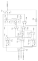
- FIG. 2 is a control block diagram of the vehicle controller 6 according to the first embodiment.
- the driver request drive torque calculator 601 calculates the driver request drive torque based on the accelerator opening. The driver required driving torque is set to a larger value as the accelerator opening degree is higher.
- the vehicle body speed estimation unit 602 estimates the vehicle body speed from the left and right driven wheel speeds detected by the rear left wheel speed sensor (driven wheel rotational speed calculation unit) 10RL and the rear right wheel speed sensor (driven wheel rotational speed calculation unit) 10RR. .
- Adder 602a adds the left and right driven wheel speeds.
- the division unit 602b outputs the value obtained by dividing the output of the addition unit 602a by 2, that is, the average value of the left and right driven wheel speeds as the vehicle body speed.
- the first vibration suppression control torque calculation unit 603 calculates the first vibration suppression control torque based on the vehicle body speed estimated by the vehicle body speed estimation unit 602 and the motor rotation speed detected by the resolver 8.
- Multiplier 603a multiplies the vehicle body speed by the total reduction ratio (reduction ratio of reduction mechanism 2 ⁇ reduction ratio of differential gear 3).
- the subtracting unit 603b subtracts the motor rotation speed from the output of the multiplication unit 603a to extract a vibration component included in the motor rotation speed.
- the high-pass filter 603c gradually reduces a steady-state deviation (deviation due to calculation of tire dynamic radius and actual deviation) component from the output of the subtraction unit 603b.
- the cutoff frequency of the high-pass filter 603c is set to a value (for example, less than 1 Hz) that can detect wheel slip.
- the gain multiplication unit 603d outputs a value obtained by multiplying the vibration component that has passed through the high-pass filter 603c by a predetermined control gain K as the first vibration suppression control torque.
- the limiter processing unit 603e limits the upper and lower limit values of the first vibration suppression control torque within a certain range.
- the second vibration suppression control torque calculator 604 calculates the second vibration suppression control torque based on the motor rotation speed.
- Multiplier 604a multiplies the motor rotation speed by -1 to invert the sign.
- the high-pass filter 604b decreases the vibration component having a predetermined frequency or less from the output of the multiplier 604a.
- the cut-off frequency of the high-pass filter 604b is a characteristic that can separate the torsional vibration frequency (for example, about 5 to 9 Hz) and the vibration frequency (for example, about 1 to 4 Hz) due to sudden acceleration in a high ⁇ road, that is,
- the rapid acceleration component included in the motor rotation speed on a high ⁇ road is set to a value that can be reduced.
- the high-pass filter type vibration suppression control torque calculator 604c calculates a second vibration suppression control torque based on the vibration component that has passed through the high-pass filter 604b.
- the gain multiplication unit 604c-1 outputs a value obtained by multiplying the vibration component that has passed through the high-pass filter 604b by a predetermined control gain K as the second vibration suppression control torque.
- the limiter processing unit 604c-2 limits the upper and lower limit values of the second vibration suppression control torque within a certain range.
- the selection unit 605 selects one of the first vibration suppression control torque calculated by the first vibration suppression control torque calculation unit 603 and the second vibration suppression control torque calculated by the second vibration suppression control torque calculation unit 604. And output as vibration suppression control torque.
- the selection unit 605 selects one of the first vibration suppression control torque and the second vibration suppression control torque according to the range position of the shift lever 12 and the motor rotation speed.
- the selection unit 605 aims to simplify the control, and always selects the first vibration suppression control torque when the vehicle is started.
- the drive torque command value calculation unit 606 calculates the drive torque command value by adding the driver request drive torque calculated by the driver request drive torque calculation unit 601 and the vibration suppression control torque output from the selection unit 605. To do.
- the rotational speed of each wheel is detected by a wheel speed sensor and input to the brake controller. Therefore, the controller that controls the electric motor obtains a driving wheel speed signal from the brake controller via the CAN communication line. become. Therefore, a communication delay occurs in the driving wheel speed acquired by the controller with respect to the actual driving wheel speed (sensor detection value). On the other hand, since the motor rotation speed is directly input from the resolver to the controller, there is no communication delay.
- the vehicle mass is separated from the apparent inertia of the tire, so that the apparent tire inertia is reduced.
- the frequency of torsional vibration (about 10 to 20 Hz) on the low ⁇ road is higher than the frequency of torsional vibration (about 5 to 9 Hz) on the high ⁇ road. For this reason, when calculating the damping braking torque while traveling on a low ⁇ road, a phase shift occurs between the vibration of the motor rotation speed and the vibration of the drive wheel speed, and improper (phase shift) vibration damping braking torque is generated. Calculated.
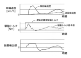
- FIG. 3 is a time chart of wheel speed, drive torque, and vibration detection value when vibration suppression control torque is calculated using a high-pass filter.
- the first vibration suppression control torque calculation unit 603 calculates the first vibration suppression control torque based on the difference between the motor rotation speed and the vehicle body speed estimated from the left and right driven wheel speeds. . Since the vehicle speed does not vibrate regardless of the slip state of the wheels, there is no phase shift from the motor rotation speed. Further, the acceleration component and the slip of the drive wheel can be distinguished by subtracting the vehicle body speed from the motor rotation speed. Therefore, the first damping control torque appropriate for the torsional vibration can be calculated regardless of the slip state of the wheel, and the effect of suppressing the torsional vibration can be improved.
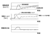
- FIG. 4 is a time chart showing the torsional vibration suppressing action when the vibration suppression control torque is obtained by the driven wheel speed method of the first embodiment.
- the motor rotation speed and the drive wheel speed are stable, slip control is not hindered, and the slip convergence performance is excellent. Yes. Furthermore, since it is not affected by communication delay, it can be applied to a conventional system that takes in the left and right driven wheel speeds from the brake controller 9 via the CAN communication line 11. Therefore, it is not necessary to add a circuit or the like for inputting the driven wheel speed directly from the wheel speed sensor 10, so that the complexity and cost increase of the system can be suppressed.
- the reason for selecting one of the first vibration suppression control torque and the second vibration suppression control torque will be described.
- the signal output from the wheel speed sensor 10 is a pulse signal, and a positive signal is output both when moving forward and when moving backward. Therefore, if the first vibration suppression control torque using the left and right driven wheel speed is used during reverse, the difference between the negative left and right driven wheel speed and the motor rotation speed is actually calculated, and the appropriate first vibration suppression control is performed. Torque cannot be calculated. Therefore, when it is considered that the vehicle is moving backward (when the R range is selected or when the rollback is reversed due to the influence of the gradient road even in the D range), the second vibration suppression control that does not use the value of the wheel speed sensor 10 The torque was selected.
- FIG. 5 is a flowchart illustrating a control process in the selection unit according to the first embodiment.
- step S1 it is determined whether or not the range position signal is the R range. If the R range is selected, it is determined that the range is reverse, and the process proceeds to step S2.
- step S2 the second vibration suppression control torque is selected.
- step S3 it is determined whether or not the motor rotation speed Nm is less than the predetermined rotation speed A1, and if it is less than A1, the process proceeds to step S2 to select the second vibration suppression control torque, and if it is greater than A1, the process proceeds to step S4.
- the predetermined rotational speed A1 is a predetermined speed indicating the reverse, for example, ⁇ 100 rpm.
- control hunting the vibration suppression control torque
- step S4 it is determined whether or not the motor rotation speed Nm is equal to or higher than the predetermined rotation speed A2. If the motor rotation speed Nm is equal to or higher than A2, the process proceeds to step S5 to select the first vibration suppression control torque.
- the predetermined rotational speed A2 is a predetermined speed at which control hunting can be avoided, and is, for example, 100 rpm. Thereby, hysteresis can be given to switching between the first vibration suppression control torque and the second vibration suppression control torque, and stable vibration suppression performance is ensured by suppressing control hunting.
- step S6 switching control for smoothly switching is performed when switching the vibration suppression control torque. Details of the switching control will be described below.
- FIG. 6 is a control block diagram illustrating the switching control process of the first embodiment.
- the previous value is represented by (1 / Z).
- the transition speed determination unit 702 in the first difference calculation unit 702a, the post-switching vibration suppression control torque and the previous value of the vibration suppression control torque currently output in the previous value output unit 708 (hereinafter referred to as the previous vibration suppression control torque).
- the limiting unit 702b if the first difference does not exceed the preset maximum and minimum limit values, the first difference is output as it is, and if it exceeds the limit value, the limit value is output. Is output. Thereby, when switching the vibration suppression control torque, the transition speed (allowable change amount per unit time at the time of transition) when shifting from one vibration suppression control torque to the other vibration suppression control torque is set.
- the second difference calculation unit 703a calculates a second difference that is a difference between the post-switching vibration suppression control torque and the post-switching vibration suppression control torque previous value.
- the compensation determination unit 703b outputs the second difference when Fch is ON, and outputs 0 when Fch is OFF.
- the adding unit 703C outputs a third difference obtained by adding the value output from the transition speed determining unit 702 and the second difference.
- the transitional vibration suppression control torque calculation unit 706 adds the previous value of the vibration suppression control torque to the third difference. Thus, even during the transition due to switching of the vibration suppression control torque, it is possible to output the vibration suppression control torque during the transition at the managed transition speed while compensating for the change caused by the post-switching vibration suppression control torque.
- the final output determination unit 707 outputs one of the post-switching vibration suppression control torque and the in-transition vibration suppression control torque based on the determination result of the transition processing determination unit 705.
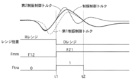
- FIG. 7 is a time chart illustrating the switching control process of the first embodiment.
- the vehicle is traveling in the R range, and the second vibration suppression control torque is selected.
- the transition processing flag Ftra is changed from 0 to 1.
- the vibration suppression control torque a value gradually asymptotically output from the second vibration suppression control torque to the first vibration suppression control torque is output.
- the transition processing flag Ftra changes from 1 to 0, and the first vibration suppression control torque is output as the vibration suppression control torque. This completes the switching.
- the vibration suppression control torque when the vibration suppression control torque is switched, even if there is a difference between the first vibration suppression control torque and the second vibration suppression control torque, the switching is performed in consideration of the change in the vibration suppression control torque after the switching. Asymptotically approaching the later vibration suppression control torque, it is possible to realize switching without causing the driver to feel uncomfortable while ensuring the vibration suppression performance.
- Example 1 the following effects are exhibited.
- a selection unit 605 (a vibration suppression control torque calculation unit) that selectively outputs vibration suppression control torque, and a motor torque command for driving the electric motor 1 based on the requested drive torque and vibration suppression control torque
- a drive torque command value calculation unit 606 (motor torque command calculation unit). Therefore, the vibration suppression effect can be improved regardless of the rotation direction of the wheel.
- the second vibration suppression control torque calculation unit 604 uses other signals than signals from the wheel speed sensor 10. Therefore, it is possible to improve the vibration suppressing effect when the vehicle is moving backward.
- the selection unit 605 uses the second vibration suppression control torque calculated by the second vibration suppression control torque calculation unit 604. That is, when the R range is selected, there is a high possibility that the vehicle will move backward, so that it is possible to accurately detect the time of backward movement.
- the selection unit 605 selects the second vibration suppression control torque when the motor rotation speed of the electric motor 1 is less than a predetermined rotation speed A1 (first threshold value) that indicates retreat. Therefore, even if negative rotation is detected by motor vibration immediately after the vehicle stops, it is not unnecessary to switch to the second vibration suppression control torque, and stable vibration suppression control can be realized.
- the selection unit 605 selects the first vibration suppression control torque when the rotation speed is greater than or equal to a predetermined rotation speed A2 (second threshold) greater than the predetermined rotation speed A1. Therefore, the vibration damping control torque is not frequently changed, and stable vibration damping control can be realized.
- the signal of the wheel speed sensor 10 is based on the rotational speed on the driven wheel side. Therefore, the effect of suppressing torsional vibration can be improved.
- a selection unit 605 that selectively outputs vibration control torque, a driver request drive torque calculation unit 601 (request drive torque calculation unit) that calculates drive torque required for the electric vehicle, drive torque, and vibration suppression And a drive torque command value calculation unit 606 (motor torque command calculation unit) that calculates a motor torque command for driving the electric motor based on the control torque.
- the selection unit 605 uses the second vibration suppression control torque calculated by the second vibration suppression control torque calculation unit 604. That is, when the R range is selected, there is a high possibility that the vehicle will move backward, so that it is possible to accurately detect the time of backward movement.
- the selection unit 605 selects the second vibration suppression control torque when the motor rotation speed of the electric motor 1 is less than a predetermined rotation speed A1 (first threshold value) that indicates retreat.
- the selection unit 605 selects the first vibration suppression control torque when the rotation speed is greater than or equal to a predetermined rotation speed A2 (second threshold) greater than the predetermined rotation speed A1. Therefore, the vibration damping control torque is not frequently changed, and stable vibration damping control can be realized.
- Step S1 for selectively outputting the control torque and the second vibration suppression control torque calculated by the second vibration suppression control torque calculation unit 604 different from the first vibration suppression control torque calculation unit 603 when the electric vehicle moves backward ⁇ S5 (damping control torque calculation step), Step S6 (motor torque command calculation step) for calculating a motor torque command for driving the electric motor 1 based on the drive torque required for the electric vehicle and the vibration suppression control torque; Equipped with. Therefore, the vibration suppression effect can be improved regardless of the rotation direction of the wheel.
- step S1 In the control system for an electric vehicle according to (13), In step S1, when the shift lever position (shift position) of the electric vehicle is in the R range (reverse position), the second vibration suppression control torque calculated by the second vibration suppression control torque calculation unit 604 is used. That is, when the R range is selected, there is a high possibility that the vehicle will move backward, so that it is possible to accurately detect the time of backward movement. (15) In the control device for an electric vehicle according to (14), In step S3, when the motor rotation speed of the electric motor 1 is less than a predetermined rotation speed A1 (first threshold value) indicating reverse, the second vibration suppression control torque is selected.
- a predetermined rotation speed A1 first threshold value
- step S4 when the second vibration suppression control torque is selected, if the rotation speed is greater than or equal to a predetermined rotation speed A2 (second threshold) greater than the predetermined rotation speed A1, the first vibration suppression control torque is selected. Therefore, the vibration damping control torque is not frequently changed, and stable vibration damping control can be realized.
- a predetermined rotation speed A2 second threshold
- the concrete structure of this invention is not limited to the structure shown in the Example, and is the range which does not deviate from the summary of invention. Any design changes are included in the present invention.
- any combination or omission of each constituent element described in the claims and the specification is possible within a range where at least a part of the above-described problems can be solved or a range where at least a part of the effect is achieved. It is.
- the electric vehicle has been described as an example, but the present invention can be applied to a hybrid vehicle including both an engine and an electric motor.
- the calculation is performed based on the rotational speed on the driven wheel side, but may be performed based on the rotational speed on the drive wheel side.
- the signal from the wheel speed sensor 10 is based on the rotational speed on the drive wheel side. In this case, the torsional vibration between the electric motor 1 and the drive wheel can be effectively suppressed.
Landscapes
- Engineering & Computer Science (AREA)
- Transportation (AREA)
- Mechanical Engineering (AREA)
- Power Engineering (AREA)
- Life Sciences & Earth Sciences (AREA)
- Sustainable Development (AREA)
- Sustainable Energy (AREA)
- Automation & Control Theory (AREA)
- Electric Propulsion And Braking For Vehicles (AREA)
Abstract
The purpose of the present invention is to provide an electric vehicle control device capable of obtaining a vibration suppression effect regardless of the wheel rotation direction. A first vibration-dampening control torque and a second vibration-dampening control torque are selectively output in one embodiment of the present invention, said first vibration-dampening control torque being calculated by using a first calculation method on the basis of a wheel speed sensor signal during forward travel of the electric vehicle and said second vibration-dampening control torque being calculated by using a second calculation method different from the first calculation method, during reverse travel of the electric vehicle.
Description
本発明は、電動車両の制御装置、制御システム及び制御方法に関する。
The present invention relates to an electric vehicle control device, a control system, and a control method.
従来の電動車両の制御装置では、モータ回転速度と左右駆動輪の平均回転速度との差分をトルク伝達系のねじり振動の振動成分として抽出し、この振動成分を打ち消すための制振制御トルクを演算し、運転者要求駆動トルクを補正している。上記説明の技術に関する一例は、特許文献1に記載されている。
In conventional electric vehicle control devices, the difference between the motor rotation speed and the average rotation speed of the left and right drive wheels is extracted as the vibration component of the torsional vibration of the torque transmission system, and the vibration suppression control torque for canceling this vibration component is calculated. The driver requested drive torque is corrected. An example relating to the technique described above is described in Patent Document 1.
しかしながら、一般的に車輪速センサの信号には符号が無く、回転方向を認識できないため、車両の後退時には正しく振動を抑制することができず、十分な振動抑制効果を得ることができないという問題があった。
本発明の目的は、車輪の回転方向に関わらず振動抑制効果を得ることが可能な電動車両の制御装置を提供することにある。 However, since the wheel speed sensor signal generally has no sign and the direction of rotation cannot be recognized, vibrations cannot be suppressed correctly when the vehicle is moving backward, and a sufficient vibration suppression effect cannot be obtained. there were.
The objective of this invention is providing the control apparatus of the electric vehicle which can acquire the vibration suppression effect irrespective of the rotation direction of a wheel.
本発明の一実施形態では、電動車両の前進時に車輪速センサの信号に基づく第1の演算方式により演算された第1制振制御トルクと、電動車両の後退時に第1の演算方式とは異なる第2の演算方式により演算された第2制振制御トルクとが、選択的に出力される。
In one embodiment of the present invention, the first vibration suppression control torque calculated by the first calculation method based on the signal of the wheel speed sensor when the electric vehicle moves forward is different from the first calculation method when the electric vehicle moves backward. The second vibration suppression control torque calculated by the second calculation method is selectively output.
よって、車輪の回転方向に関わらず振動抑制効果を得ることができる。
Therefore, the vibration suppressing effect can be obtained regardless of the rotation direction of the wheel.
〔実施例1〕
図1は実施例1の電動車両のシステム図である。実施例1の電動車両は、前輪FL,FRが電動モータ1により駆動される前輪駆動車(二輪駆動車)である。電動モータ1には減速機構2を介してディファレンシャルギア3が接続されている。ディファレンシャルギア3にはドライブシャフト4が接続されている。ドライブシャフト4には前輪FL,FRが接続されている。電動モータ1は、インバータ5を介して図外の高電圧バッテリから電力が供給される。インバータ5の駆動は、車両コントローラ6により制御される。 [Example 1]
FIG. 1 is a system diagram of the electric vehicle according to the first embodiment. The electric vehicle according to the first embodiment is a front wheel drive vehicle (two-wheel drive vehicle) in which the front wheels FL and FR are driven by theelectric motor 1. A differential gear 3 is connected to the electric motor 1 via a speed reduction mechanism 2. A drive shaft 4 is connected to the differential gear 3. Front wheels FL and FR are connected to the drive shaft 4. The electric motor 1 is supplied with electric power from a high voltage battery (not shown) via the inverter 5. The drive of the inverter 5 is controlled by the vehicle controller 6.
図1は実施例1の電動車両のシステム図である。実施例1の電動車両は、前輪FL,FRが電動モータ1により駆動される前輪駆動車(二輪駆動車)である。電動モータ1には減速機構2を介してディファレンシャルギア3が接続されている。ディファレンシャルギア3にはドライブシャフト4が接続されている。ドライブシャフト4には前輪FL,FRが接続されている。電動モータ1は、インバータ5を介して図外の高電圧バッテリから電力が供給される。インバータ5の駆動は、車両コントローラ6により制御される。 [Example 1]
FIG. 1 is a system diagram of the electric vehicle according to the first embodiment. The electric vehicle according to the first embodiment is a front wheel drive vehicle (two-wheel drive vehicle) in which the front wheels FL and FR are driven by the
電動車両は、車両の走行モードを表すレンジ位置信号を出力するシフトレバー12と、アクセル開度信号を出力するアクセル開度センサ7と、電動モータ1の回転方向を含むモータ回転速度信号を出力するレゾルバ8と、を有する。車両コントローラ6は、シフトレバー12からのレンジ位置信号と、アクセル開度センサ7からのアクセル開度信号とを受信する第1の受信部を有する。また、車両コントローラ6は、レゾルバ8からのモータ回転速度信号を、インバータ5を介して受信する第2の受信部を有する。シフトレバー12は、運転者により操作され、車両停車時はパーキングレンジ(以下、Pレンジ)、非動力伝達時はニュートラルレンジ(以下、Nレンジ)、前進時はドライブレンジ(以下、Dレンジ)、後退時はリバースレンジ(以下、Rレンジ)のレンジ位置信号を出力する。尚、特許請求の範囲に記載の「シフト位置がリバース位置」とは、シフトレバー12のレバー位置とRレンジ位置を示す表示位置とが対応しているかに関わらず、シフトレバー12がRレンジ位置信号を出力していることを意味する。
The electric vehicle outputs a shift lever 12 that outputs a range position signal that represents the travel mode of the vehicle, an accelerator opening sensor 7 that outputs an accelerator opening signal, and a motor rotation speed signal that includes the rotation direction of the electric motor 1. And a resolver 8. The vehicle controller 6 has a first receiver that receives a range position signal from the shift lever 12 and an accelerator opening signal from the accelerator opening sensor 7. Further, the vehicle controller 6 has a second receiving unit that receives the motor rotation speed signal from the resolver 8 via the inverter 5. The shift lever 12 is operated by the driver. When the vehicle is stopped, the parking range (hereinafter referred to as P range), the non-power transmission during the neutral range (hereinafter referred to as N range), the forward drive range (hereinafter referred to as D range), When reverse, the range position signal of the reverse range (hereinafter R range) is output. In addition, “the shift position is the reverse position” described in the claims means that the shift lever 12 is in the R range position regardless of whether the lever position of the shift lever 12 corresponds to the display position indicating the R range position. This means that a signal is being output.
インバータ5は、ブレーキコントローラ9を介して後輪RL,RRの車輪速度(左従動輪速度,右従動輪速度)を受信する。ブレーキコントローラ9は、各輪に設けられた車輪速センサ10FL,10FR,10RL,10RR(以下、単に10とも記載する。)と接続され、各輪の回転速度信号を受信する。車輪速センサ10は、電磁バルスの周期から車輪速を検出するため、回転方向は検出できない。ブレーキコントローラ9は、運転者のブレーキ操作量、各車輪速度等に基づき、各輪のブレーキユニットに供給するブレーキ液を調整し、各輪の制動トルクを制御する。インバータ5、車両コントローラ6およびブレーキコントローラ9の情報通信は、CAN通信線(通信装置)11を介して行われる。車両コントローラ6は、アクセル開度等に基づいて電動モータ1の駆動トルク指令値を演算し、駆動トルク指令値に応じてインバータ5を駆動する。
The inverter 5 receives the wheel speeds (left driven wheel speed, right driven wheel speed) of the rear wheels RL and RR via the brake controller 9. The brake controller 9 is connected to wheel speed sensors 10FL, 10FR, 10RL, 10RR (hereinafter also simply referred to as 10) provided on each wheel, and receives a rotation speed signal of each wheel. Since the wheel speed sensor 10 detects the wheel speed from the period of the electromagnetic pulse, the rotation direction cannot be detected. The brake controller 9 adjusts the brake fluid supplied to the brake unit of each wheel based on the brake operation amount of the driver, each wheel speed, etc., and controls the braking torque of each wheel. Information communication between the inverter 5, the vehicle controller 6 and the brake controller 9 is performed via a CAN communication line (communication device) 11. The vehicle controller 6 calculates a drive torque command value for the electric motor 1 based on the accelerator opening and the like, and drives the inverter 5 according to the drive torque command value.
図2は、実施例1の車両コントローラ6の制御ブロック図である。
運転者要求駆動トルク演算部601は、アクセル開度に基づき運転者要求駆動トルクを演算する。運転者要求駆動トルクは、アクセル開度が高いほど大きな値とする。
車体速度推定部602は、後左車輪速センサ(従動輪回転速度演算部)10RLおよび後右車輪速センサ(従動輪回転速度演算部)10RRにより検出された左右従動輪速度から車体速度を推定する。加算部602aは、左右従動輪速度を加算する。除算部602bは、加算部602aの出力を2で除した値、すなわち、左右従動輪速度の平均値を車体速度として出力する。 FIG. 2 is a control block diagram of the vehicle controller 6 according to the first embodiment.
The driver requestdrive torque calculator 601 calculates the driver request drive torque based on the accelerator opening. The driver required driving torque is set to a larger value as the accelerator opening degree is higher.
The vehicle bodyspeed estimation unit 602 estimates the vehicle body speed from the left and right driven wheel speeds detected by the rear left wheel speed sensor (driven wheel rotational speed calculation unit) 10RL and the rear right wheel speed sensor (driven wheel rotational speed calculation unit) 10RR. . Adder 602a adds the left and right driven wheel speeds. The division unit 602b outputs the value obtained by dividing the output of the addition unit 602a by 2, that is, the average value of the left and right driven wheel speeds as the vehicle body speed.
運転者要求駆動トルク演算部601は、アクセル開度に基づき運転者要求駆動トルクを演算する。運転者要求駆動トルクは、アクセル開度が高いほど大きな値とする。
車体速度推定部602は、後左車輪速センサ(従動輪回転速度演算部)10RLおよび後右車輪速センサ(従動輪回転速度演算部)10RRにより検出された左右従動輪速度から車体速度を推定する。加算部602aは、左右従動輪速度を加算する。除算部602bは、加算部602aの出力を2で除した値、すなわち、左右従動輪速度の平均値を車体速度として出力する。 FIG. 2 is a control block diagram of the vehicle controller 6 according to the first embodiment.
The driver request
The vehicle body
第1制振制御トルク演算部603は、車体速度推定部602により推定された車体速度とレゾルバ8により検出されたモータ回転速度とに基づいて第1制振制御トルクを演算する。乗算部603aは、車体速度に総減速比(減速機構2の減速比×ディファレンシャルギア3の減速比)を乗じる。減算部603bは、乗算部603aの出力からモータ回転速度を減じてモータ回転速度に含まれる振動成分を抽出する。ハイパスフィルタ603cは、減算部603bの出力から定常偏差(タイヤ動半径の計算と実際のずれによる偏差)成分を逓減させる。ハイパスフィルタ603cのカットオフ周波数は、車輪スリップを検出可能な値(例えば、1Hz未満)とする。ゲイン乗算部603dは、ハイパスフィルタ603cを通過した振動成分に所定の制御ゲインKを乗じた値を第1制振制御トルクとして出力する。リミッタ処理部603eは、第1制振制御トルクの上下限値を一定範囲内に制限する。
The first vibration suppression control torque calculation unit 603 calculates the first vibration suppression control torque based on the vehicle body speed estimated by the vehicle body speed estimation unit 602 and the motor rotation speed detected by the resolver 8. Multiplier 603a multiplies the vehicle body speed by the total reduction ratio (reduction ratio of reduction mechanism 2 × reduction ratio of differential gear 3). The subtracting unit 603b subtracts the motor rotation speed from the output of the multiplication unit 603a to extract a vibration component included in the motor rotation speed. The high-pass filter 603c gradually reduces a steady-state deviation (deviation due to calculation of tire dynamic radius and actual deviation) component from the output of the subtraction unit 603b. The cutoff frequency of the high-pass filter 603c is set to a value (for example, less than 1 Hz) that can detect wheel slip. The gain multiplication unit 603d outputs a value obtained by multiplying the vibration component that has passed through the high-pass filter 603c by a predetermined control gain K as the first vibration suppression control torque. The limiter processing unit 603e limits the upper and lower limit values of the first vibration suppression control torque within a certain range.
第2制振制御トルク演算部604は、モータ回転速度に基づいて第2制振制御トルクを演算する。乗算部604aは、モータ回転速度に-1を乗じて符号を反転させる。ハイパスフィルタ604bは、乗算器604aの出力から所定の周波数以下の振動成分を逓減させる。ハイパスフィルタ604bのカットオフ周波数は、高μ路におけるねじり振動の周波数(例えば、5~9Hz程度)と急加速による振動の周波数(例えば、1~4Hz程度)とを分離できるような特性、すなわち、高μ路においてモータ回転速度に含まれる急加速成分を逓減可能な値とする。ハイパスフィルタ方式制振制御トルク演算部604cは、ハイパスフィルタ604bを通過した振動成分に基づいて第2制振制御トルクを演算する。ゲイン乗算部604c-1は、ハイパスフィルタ604bを通過した振動成分に所定の制御ゲインKを乗じた値を第2制振制御トルクとして出力する。リミッタ処理部604c-2は、第2制振制御トルクの上下限値を一定範囲内に制限する。
The second vibration suppression control torque calculator 604 calculates the second vibration suppression control torque based on the motor rotation speed. Multiplier 604a multiplies the motor rotation speed by -1 to invert the sign. The high-pass filter 604b decreases the vibration component having a predetermined frequency or less from the output of the multiplier 604a. The cut-off frequency of the high-pass filter 604b is a characteristic that can separate the torsional vibration frequency (for example, about 5 to 9 Hz) and the vibration frequency (for example, about 1 to 4 Hz) due to sudden acceleration in a high μ road, that is, The rapid acceleration component included in the motor rotation speed on a high μ road is set to a value that can be reduced. The high-pass filter type vibration suppression control torque calculator 604c calculates a second vibration suppression control torque based on the vibration component that has passed through the high-pass filter 604b. The gain multiplication unit 604c-1 outputs a value obtained by multiplying the vibration component that has passed through the high-pass filter 604b by a predetermined control gain K as the second vibration suppression control torque. The limiter processing unit 604c-2 limits the upper and lower limit values of the second vibration suppression control torque within a certain range.
選択部605は、第1制振制御トルク演算部603により演算された第1制振制御トルクと、第2制振制御トルク演算部604により演算された第2制振制御トルクの一方を選択し、制振制御トルクとして出力する。選択部605は、シフトレバー12のレンジ位置やモータ回転速度に応じて第1制振制御トルクと第2制振制御トルクの一方を選択する。なお、選択部605は、制御の簡素化を狙いとし、車両起動時には常に第1制振制御トルクを選択する。
駆動トルク指令値演算部606は、運転者要求駆動トルク演算部601により演算された運転者要求駆動トルクと、選択部605から出力された制振制御トルクとを加算して駆動トルク指令値を演算する。 Theselection unit 605 selects one of the first vibration suppression control torque calculated by the first vibration suppression control torque calculation unit 603 and the second vibration suppression control torque calculated by the second vibration suppression control torque calculation unit 604. And output as vibration suppression control torque. The selection unit 605 selects one of the first vibration suppression control torque and the second vibration suppression control torque according to the range position of the shift lever 12 and the motor rotation speed. The selection unit 605 aims to simplify the control, and always selects the first vibration suppression control torque when the vehicle is started.
The drive torque commandvalue calculation unit 606 calculates the drive torque command value by adding the driver request drive torque calculated by the driver request drive torque calculation unit 601 and the vibration suppression control torque output from the selection unit 605. To do.
駆動トルク指令値演算部606は、運転者要求駆動トルク演算部601により演算された運転者要求駆動トルクと、選択部605から出力された制振制御トルクとを加算して駆動トルク指令値を演算する。 The
The drive torque command
[ねじり振動の抑制効果の向上]
電動車両において、急加速時にモータトルクをステップ的に立ち上げると、ドライブシャフトのねじれと解放が繰り返されることに起因してトルク伝達系にねじり振動が生じる。電動モータはエンジンに対してトルク応答性が高いため、ねじり振動がマウントを介して車体に伝達されると、特に車体の共振周波数と重なったとき、乗り心地の低下や振動・騒音レベルの増大を招く。そこで、従来の電動車両では、モータ回転速度と左右駆動輪の平均回転速度(駆動輪速度)との差分をねじり振動の振動成分として抽出し、この振動成分を打ち消すための制振制御トルクを演算して運転者要求駆動トルクを補正している。
しかしながら、モータ回転速度と駆動輪速度との差分から制振制御トルクを求める場合、特に低μ路走行中のねじり振動に対して適切な制振制御トルクを演算できず、十分な振動抑制効果が得られない。以下にその理由を説明する。 [Improved torsional vibration suppression effect]
In an electric vehicle, when the motor torque is increased stepwise during sudden acceleration, torsional vibration occurs in the torque transmission system due to repeated torsion and release of the drive shaft. Since the electric motor has high torque response to the engine, when torsional vibrations are transmitted to the vehicle body via the mount, especially when it overlaps with the resonance frequency of the vehicle body, it reduces the ride comfort and increases the vibration and noise levels. Invite. Therefore, in a conventional electric vehicle, the difference between the motor rotation speed and the average rotation speed of the left and right drive wheels (drive wheel speed) is extracted as a vibration component of torsional vibration, and the vibration suppression control torque for canceling this vibration component is calculated. Thus, the driver required driving torque is corrected.
However, when obtaining the vibration suppression control torque from the difference between the motor rotation speed and the drive wheel speed, it is not possible to calculate an appropriate vibration suppression control torque especially for torsional vibration during low-μ road traveling. I can't get it. The reason will be described below.
一般的に、各輪の回転速度は車輪速センサにより検出されてブレーキコントローラへ入力されるため、電動モータを制御するコントローラは、CAN通信線を介してブレーキコントローラから駆動輪速度信号を取得することになる。よって、実際の駆動輪速度(センサ検出値)に対してコントローラが取得する駆動輪速度には通信遅れが生じる。一方、モータ回転速度はレゾルバから直接コントローラへ入力されるため、通信遅れは生じない。ここで、低μ路で車輪のスリップが生じると、タイヤの見かけの慣性から車両質量が切り離されるため、見かけのタイヤ慣性が小さくなる。そのため、低μ路におけるねじり振動の周波数(10~20Hz程度)は、高μ路におけるねじり振動の周波数(5~9Hz程度)よりも高い。このため、低μ路走行中に制振制動トルクを演算する際、モータ回転速度の振動と駆動輪速度の振動との位相ズレが生じ、不適切(位相のズレた)な制振制動トルクが演算される。
In general, the rotational speed of each wheel is detected by a wheel speed sensor and input to the brake controller. Therefore, the controller that controls the electric motor obtains a driving wheel speed signal from the brake controller via the CAN communication line. become. Therefore, a communication delay occurs in the driving wheel speed acquired by the controller with respect to the actual driving wheel speed (sensor detection value). On the other hand, since the motor rotation speed is directly input from the resolver to the controller, there is no communication delay. Here, when wheel slip occurs on a low μ road, the vehicle mass is separated from the apparent inertia of the tire, so that the apparent tire inertia is reduced. Therefore, the frequency of torsional vibration (about 10 to 20 Hz) on the low μ road is higher than the frequency of torsional vibration (about 5 to 9 Hz) on the high μ road. For this reason, when calculating the damping braking torque while traveling on a low μ road, a phase shift occurs between the vibration of the motor rotation speed and the vibration of the drive wheel speed, and improper (phase shift) vibration damping braking torque is generated. Calculated.
なお、上記の通信遅れによる影響を回避する方法としては、CAN通信線を介さずに車輪速センサから直接駆動輪速度を入力する方法、モータ回転速度からハイパスフィルタを用いて制振制御トルクを演算する方法が知られている。しかしながら、前者にあっては、回路の追加等、コストアップが問題となる。また、後者にあっては、駆動輪のスリップによりスリップ初期に位相のズレた制振制御トルクが演算されることで、スリップ制御性能の低下を招く。図3は、ハイパスフィルタを用いて制振制御トルクを演算した場合の車輪速度、駆動トルクおよび振動検出値のタイムチャートである。ハイパスフィルタを用いた方法では、駆動輪のスリップ(=モータ速度の上昇)と急加速を判別できないため、スリップ初期において駆動輪のスリップに対し位相のズレた制振制御トルクが演算される。よって、モータ回転速度及び駆動輪速度が安定せず、スリップ制御性能が低下している。
As a method to avoid the influence of the communication delay described above, the driving wheel speed is directly input from the wheel speed sensor without using the CAN communication line, and the vibration suppression control torque is calculated from the motor rotation speed using a high-pass filter. How to do is known. However, in the former case, a cost increase such as addition of a circuit becomes a problem. In the latter case, slip control performance is deteriorated by calculating a vibration suppression control torque having a phase shift at the initial stage of slip due to slip of the drive wheels. FIG. 3 is a time chart of wheel speed, drive torque, and vibration detection value when vibration suppression control torque is calculated using a high-pass filter. In the method using the high-pass filter, since slip of the drive wheel (= increase in motor speed) and sudden acceleration cannot be discriminated, a vibration damping control torque having a phase shift with respect to the slip of the drive wheel is calculated at the initial stage of the slip. Therefore, the motor rotation speed and the driving wheel speed are not stable, and the slip control performance is deteriorated.
これに対し、実施例1では、第1制振制御トルク演算部603において、モータ回転速度と左右従動輪速度から推定した車体速度との差分に基づいて第1制振制御トルクを演算している。車体速度は車輪のスリップ状態にかかわらず振動しないため、モータ回転速度との位相ズレは生じない。また、モータ回転速度から車体速度を減じることで加速成分と駆動輪のスリップとを区別できる。よって、車輪のスリップ状態にかかわらずねじり振動に対して適切な第1制振制御トルクを演算でき、ねじり振動の抑制効果を向上できる。図4は、実施例1の従動輪速方式で制振制御トルクを求めた場合のねじり振動抑制作用を示すタイムチャートである。実施例1では、駆動輪のスリップに対して位相ズレなく振動を検出できるため、モータ回転速度および駆動輪速度が安定しており、スリップ制御を阻害することがなく、スリップの収束性能に優れている。さらに、通信遅れの影響を受けないため、ブレーキコントローラ9からCAN通信線11を介して左右従動輪速度を取り込む従前のシステムに適用できる。よって、車輪速センサ10から直接従動輪速度を入力する回路等の追加が不要であるため、システムの複雑化およびコストアップを抑制できる。
In contrast, in the first embodiment, the first vibration suppression control torque calculation unit 603 calculates the first vibration suppression control torque based on the difference between the motor rotation speed and the vehicle body speed estimated from the left and right driven wheel speeds. . Since the vehicle speed does not vibrate regardless of the slip state of the wheels, there is no phase shift from the motor rotation speed. Further, the acceleration component and the slip of the drive wheel can be distinguished by subtracting the vehicle body speed from the motor rotation speed. Therefore, the first damping control torque appropriate for the torsional vibration can be calculated regardless of the slip state of the wheel, and the effect of suppressing the torsional vibration can be improved. FIG. 4 is a time chart showing the torsional vibration suppressing action when the vibration suppression control torque is obtained by the driven wheel speed method of the first embodiment. In the first embodiment, since vibration can be detected without phase shift with respect to slip of the drive wheel, the motor rotation speed and the drive wheel speed are stable, slip control is not hindered, and the slip convergence performance is excellent. Yes. Furthermore, since it is not affected by communication delay, it can be applied to a conventional system that takes in the left and right driven wheel speeds from the brake controller 9 via the CAN communication line 11. Therefore, it is not necessary to add a circuit or the like for inputting the driven wheel speed directly from the wheel speed sensor 10, so that the complexity and cost increase of the system can be suppressed.
ここで、第1制振制御トルクと第2制振制御トルクのいずれか一方を選択する理由について説明する。上述したように、車輪速センサ10が出力する信号は、パルス信号であり、前進時も後退時も正の信号を出力する。よって、後退時に左右従動輪速度を用いた第1制振制御トルクを使用すると、実際には負の左右従動輪速度とモータ回転速度との差分を演算してしまい、適正な第1制振制御トルクを演算することができない。そこで、後退していると考えられる場合(Rレンジ選択時や、Dレンジであっても勾配路の影響で後退するロールバック時)は、車輪速センサ10の値を用いない第2制振制御トルクを選択することとした。
Here, the reason for selecting one of the first vibration suppression control torque and the second vibration suppression control torque will be described. As described above, the signal output from the wheel speed sensor 10 is a pulse signal, and a positive signal is output both when moving forward and when moving backward. Therefore, if the first vibration suppression control torque using the left and right driven wheel speed is used during reverse, the difference between the negative left and right driven wheel speed and the motor rotation speed is actually calculated, and the appropriate first vibration suppression control is performed. Torque cannot be calculated. Therefore, when it is considered that the vehicle is moving backward (when the R range is selected or when the rollback is reversed due to the influence of the gradient road even in the D range), the second vibration suppression control that does not use the value of the wheel speed sensor 10 The torque was selected.
図5は実施例1の選択部における制御処理を表すフローチャートである。
ステップS1では、レンジ位置信号がRレンジか否かを判断し、Rレンジが選択されているときは、後退すると判断してステップS2に進む。
ステップS2では、第2制振制御トルクを選択する。
ステップS3では、モータ回転速度Nmが所定回転速度A1未満か否かを判断し、A1未満のときはステップS2に進んで第2制振制御トルクを選択し、A1以上のときはステップS4に進む。ここで、所定回転速度A1は、後退を表す所定速度であり、例えば-100rpmである。ここで、0rpmではなく負の値を設定したのは、停車直後の振動によってモータ回転速度Nmが0rpm付近で負と正との間を行き来する場合があり、第1制振制御トルクと第2制振制御トルクとの切り替えが頻繁に行われる(以下、制御ハンチングと記載する。)ことによる制御性の悪化を回避するためである。 FIG. 5 is a flowchart illustrating a control process in the selection unit according to the first embodiment.
In step S1, it is determined whether or not the range position signal is the R range. If the R range is selected, it is determined that the range is reverse, and the process proceeds to step S2.
In step S2, the second vibration suppression control torque is selected.
In step S3, it is determined whether or not the motor rotation speed Nm is less than the predetermined rotation speed A1, and if it is less than A1, the process proceeds to step S2 to select the second vibration suppression control torque, and if it is greater than A1, the process proceeds to step S4. . Here, the predetermined rotational speed A1 is a predetermined speed indicating the reverse, for example, −100 rpm. Here, the negative value is set instead of 0 rpm because the motor rotation speed Nm sometimes goes back and forth between negative and positive in the vicinity of 0 rpm due to vibration immediately after the vehicle stops. This is to avoid deterioration in controllability due to frequent switching to the vibration suppression control torque (hereinafter referred to as control hunting).
ステップS4では、モータ回転速度Nmが所定回転速度A2以上か否かを判断し、A2以上のときはステップS5に進んで第1制振制御トルクを選択し、A2未満の場合はステップS1に戻る。ここで、所定回転速度A2は、制御ハンチングを回避可能な所定速度であり、例えば100rpmである。これにより、第1制振制御トルクと第2制振制御トルクとの切り替えにヒステリシスを持たせることができ、制御ハンチングを抑制することで安定した制振性能を確保する。
ステップS6では、制振制御トルクを切り替える際に、スムーズに切り替える切り替え制御を実行する。以下、切り替え制御の詳細について説明する。 In step S4, it is determined whether or not the motor rotation speed Nm is equal to or higher than the predetermined rotation speed A2. If the motor rotation speed Nm is equal to or higher than A2, the process proceeds to step S5 to select the first vibration suppression control torque. . Here, the predetermined rotational speed A2 is a predetermined speed at which control hunting can be avoided, and is, for example, 100 rpm. Thereby, hysteresis can be given to switching between the first vibration suppression control torque and the second vibration suppression control torque, and stable vibration suppression performance is ensured by suppressing control hunting.
In step S6, switching control for smoothly switching is performed when switching the vibration suppression control torque. Details of the switching control will be described below.
(切り替え制御処理について) 図6は実施例1の切り替え制御処理を表す制御ブロック図である。図中、(1/Z)で表されるのは、前回値である。切り替えフラグFmmは、第1制振制御トルクから第2制振制御トルクへの切り替えが起こったときはFmm=F12を出力し、第2制振制御トルクから第1制振制御トルクへの切り替えが起こった時はFmm=F21を出力する。
トルク切り替え部700では、切り替えフラグFmmの値に応じた切り替え後制振制御トルクを出力する。言い換えると、Fmm=F12のときは第2制振制御トルクが切り替え後制振制御トルクであり、Fmm=F21のときは第1制振制御トルクが切り替え後制振制御トルクである。 (Switching Control Process) FIG. 6 is a control block diagram illustrating the switching control process of the first embodiment. In the figure, the previous value is represented by (1 / Z). The switching flag Fmm outputs Fmm = F12 when the switching from the first damping control torque to the second damping control torque occurs, and the switching from the second damping control torque to the first damping control torque is performed. When this happens, Fmm = F21 is output.
Thetorque switching unit 700 outputs a post-switching vibration damping control torque corresponding to the value of the switching flag Fmm. In other words, when Fmm = F12, the second vibration suppression control torque is the post-switching vibration suppression control torque, and when Fmm = F21, the first vibration suppression control torque is the post-switching vibration suppression control torque.
トルク切り替え部700では、切り替えフラグFmmの値に応じた切り替え後制振制御トルクを出力する。言い換えると、Fmm=F12のときは第2制振制御トルクが切り替え後制振制御トルクであり、Fmm=F21のときは第1制振制御トルクが切り替え後制振制御トルクである。 (Switching Control Process) FIG. 6 is a control block diagram illustrating the switching control process of the first embodiment. In the figure, the previous value is represented by (1 / Z). The switching flag Fmm outputs Fmm = F12 when the switching from the first damping control torque to the second damping control torque occurs, and the switching from the second damping control torque to the first damping control torque is performed. When this happens, Fmm = F21 is output.
The
移行処理開始判断部701では、判断部701aにおいて切り替えフラグFmmの値が前回値と不一致か否かを判断し、不一致のとき(F12→F21への切り替え、もしくはF21→F12への切り替え)が起こったときはFch=ONを出力し、それ以外の場合はFch=OFFを出力する。
移行速度決定部702では、第1差分演算部702aにおいて、切り替え後制振制御トルクと前回値出力部708において現在出力されている制振制御トルクの前回値(以下、前回制振制御トルクと記載する。)との差分である第1差分を演算する。次に、制限部702bでは、第1差分が予め設定された変化量の最大及び最小の制限値を超えていない場合は、第1差分をそのまま出力し、制限値を超えている場合は制限値を出力する。これにより、制振制御トルクを切り替える際に、一方の制振制御トルクから他方の制振制御トルクへ移行する際の移行速度(移行時の単位時間当たりにおける許容変化量)を設定する。 In the transition processingstart determination unit 701, the determination unit 701a determines whether or not the value of the switching flag Fmm does not match the previous value, and a mismatch occurs (switching from F12 to F21 or switching from F21 to F12). When this happens, Fch = ON is output, otherwise Fch = OFF is output.
In the transitionspeed determination unit 702, in the first difference calculation unit 702a, the post-switching vibration suppression control torque and the previous value of the vibration suppression control torque currently output in the previous value output unit 708 (hereinafter referred to as the previous vibration suppression control torque). To calculate the first difference, which is the difference from Next, in the limiting unit 702b, if the first difference does not exceed the preset maximum and minimum limit values, the first difference is output as it is, and if it exceeds the limit value, the limit value is output. Is output. Thereby, when switching the vibration suppression control torque, the transition speed (allowable change amount per unit time at the time of transition) when shifting from one vibration suppression control torque to the other vibration suppression control torque is set.
移行速度決定部702では、第1差分演算部702aにおいて、切り替え後制振制御トルクと前回値出力部708において現在出力されている制振制御トルクの前回値(以下、前回制振制御トルクと記載する。)との差分である第1差分を演算する。次に、制限部702bでは、第1差分が予め設定された変化量の最大及び最小の制限値を超えていない場合は、第1差分をそのまま出力し、制限値を超えている場合は制限値を出力する。これにより、制振制御トルクを切り替える際に、一方の制振制御トルクから他方の制振制御トルクへ移行する際の移行速度(移行時の単位時間当たりにおける許容変化量)を設定する。 In the transition processing
In the transition
移行中制振性能補償部703では、第2差分演算部703aにおいて、切り替え後制振制御トルクと切り替え後制振制御トルク前回値との差分である第2差分を演算する。次に、補償判断部703bにおいて、FchがONのときは第2差分を出力し、FchがOFFのときは0を出力する。そして、加算部703Cにおいて、移行速度決定部702から出力された値と、第2差分とを加算した第3差分を出力する。これにより、完全に切り替え後制振制御トルクに切り替えられる前であっても、切り替え後制振制御トルクの変化分を補償し、制振性能を確保する。
In the transition vibration suppression performance compensation unit 703, the second difference calculation unit 703a calculates a second difference that is a difference between the post-switching vibration suppression control torque and the post-switching vibration suppression control torque previous value. Next, the compensation determination unit 703b outputs the second difference when Fch is ON, and outputs 0 when Fch is OFF. Then, the adding unit 703C outputs a third difference obtained by adding the value output from the transition speed determining unit 702 and the second difference. As a result, even before switching to the post-switching vibration suppression control torque, the amount of change in the post-switching vibration suppression control torque is compensated to ensure the vibration suppression performance.
移行処理終了判断部704では、第1差分と制限後の第1差分(制限値もしくは第1差分のいずれか)とが一致するか否かを判断し、一致するときは第1差分が制限値よりも小さため、制振制御トルクが切り替え後制振制御トルクに追いついたと判断してFend=ONを出力し、一致していないときは制限されている状態であり、まだ制振制御トルクが切り替え後制振制御トルクに追いついていないと判断してFend=OFFを出力する。
The transition processing end determination unit 704 determines whether the first difference and the first difference after the restriction (either the restriction value or the first difference) match, and if they match, the first difference is the restriction value. Therefore, it is judged that the vibration suppression control torque has caught up with the vibration suppression control torque after switching, Fend = ON is output, and when it does not match, it is in a restricted state, and the vibration suppression control torque is still switched Fend = OFF is output because it is determined that the rear damping control torque has not been caught up.
移行処理中判断部705では、第1判断部705aにおいて、FchがOFFのときは移行処理中フラグFtra=1を出力し、FchがONのときは後述する第2判断部705bの判断結果を出力する。第2判断部705bでは、FendがONのときは0を出力し、FendがOFFのときは第1判断部705aから出力された値の前回値を出力する。言い換えると、制振制御トルクの切り替え要求が出力されたときは、一旦Ftra=1を出力し、その後、切り替え要求が終了すると、第2判断部705bの判断結果に切り替える。このとき、FendがOFFの間は第2判断部705bの判断結果が1であるから、第1判断部705aからは継続的にFtra=1が出力される。その後、第2判断部705bの判断結果が0となると、第1判断部705aにも0が出力されるため、第1判断部705aからFtr=0が出力される。
In the transition processing determination unit 705, the first determination unit 705a outputs a transition processing flag Ftra = 1 when Fch is OFF, and outputs the determination result of the second determination unit 705b described later when Fch is ON. To do. The second determination unit 705b outputs 0 when Fend is ON, and outputs the previous value of the value output from the first determination unit 705a when Fend is OFF. In other words, when a vibration control torque switching request is output, Ftra = 1 is output once, and when the switching request ends, the determination result of the second determination unit 705b is switched. At this time, since the determination result of the second determination unit 705b is 1 while Fend is OFF, Ftra = 1 is continuously output from the first determination unit 705a. Thereafter, when the determination result of the second determination unit 705b becomes 0, 0 is also output to the first determination unit 705a, so that Ftr = 0 is output from the first determination unit 705a.
移行中制振制御トルク演算部706では、第3差分に制振制御トルク前回値を加算する。これにより、制振制御トルクの切り替えに伴う移行中であっても、切り替え後制振制御トルクによる変化分を補償しつつ、管理された移行速度によって移行中制振制御トルクを出力できる。
最終出力判断部707では、移行処理中判断部705の判断結果に基づいて、切り替え後制振制御トルクと移行中制振制御トルクとのうち、いずれかを出力する。 The transitional vibration suppression controltorque calculation unit 706 adds the previous value of the vibration suppression control torque to the third difference. Thus, even during the transition due to switching of the vibration suppression control torque, it is possible to output the vibration suppression control torque during the transition at the managed transition speed while compensating for the change caused by the post-switching vibration suppression control torque.
The finaloutput determination unit 707 outputs one of the post-switching vibration suppression control torque and the in-transition vibration suppression control torque based on the determination result of the transition processing determination unit 705.
最終出力判断部707では、移行処理中判断部705の判断結果に基づいて、切り替え後制振制御トルクと移行中制振制御トルクとのうち、いずれかを出力する。 The transitional vibration suppression control
The final
図7は実施例1の切り替え制御処理を表すタイムチャートである。最初はRレンジでの走行中であって、第2制振制御トルクが選択された状態である。
時刻t1において、運転者がシフトレバー12を操作し、RレンジからDレンジにシフト動作を行い、切り替えフラグFmmがF12からF21に切り替わると、移行処理中フラグFtraが0から1に変化する。そして、制振制御トルクは、第2制振制御トルクから第1制振制御トルクへと徐々に漸近した値が出力される。
時刻t2において、制振制御トルクと第1制振制御トルクとが一致すると、移行処理中フラグFtraが1から0に変化し、制振制御トルクとして第1制振制御トルクが出力される。これにより、完全に切り替えが完了する。
このように、制振制御トルクが切り替えられる際、第1制振制御トルクと第2制振制御トルクとに乖離があったとしても、切り替え後の制振制御トルクの変化分を考慮しつつ切り替え後の制振制御トルクに漸近することで、制振性能を確保しつつ運転者に違和感の無い切り替えを実現できる。 FIG. 7 is a time chart illustrating the switching control process of the first embodiment. Initially, the vehicle is traveling in the R range, and the second vibration suppression control torque is selected.
At time t1, when the driver operates theshift lever 12 to perform the shift operation from the R range to the D range and the switching flag Fmm is switched from F12 to F21, the transition processing flag Ftra is changed from 0 to 1. As the vibration suppression control torque, a value gradually asymptotically output from the second vibration suppression control torque to the first vibration suppression control torque is output.
When the vibration suppression control torque and the first vibration suppression control torque match at time t2, the transition processing flag Ftra changes from 1 to 0, and the first vibration suppression control torque is output as the vibration suppression control torque. This completes the switching.
As described above, when the vibration suppression control torque is switched, even if there is a difference between the first vibration suppression control torque and the second vibration suppression control torque, the switching is performed in consideration of the change in the vibration suppression control torque after the switching. Asymptotically approaching the later vibration suppression control torque, it is possible to realize switching without causing the driver to feel uncomfortable while ensuring the vibration suppression performance.
時刻t1において、運転者がシフトレバー12を操作し、RレンジからDレンジにシフト動作を行い、切り替えフラグFmmがF12からF21に切り替わると、移行処理中フラグFtraが0から1に変化する。そして、制振制御トルクは、第2制振制御トルクから第1制振制御トルクへと徐々に漸近した値が出力される。
時刻t2において、制振制御トルクと第1制振制御トルクとが一致すると、移行処理中フラグFtraが1から0に変化し、制振制御トルクとして第1制振制御トルクが出力される。これにより、完全に切り替えが完了する。
このように、制振制御トルクが切り替えられる際、第1制振制御トルクと第2制振制御トルクとに乖離があったとしても、切り替え後の制振制御トルクの変化分を考慮しつつ切り替え後の制振制御トルクに漸近することで、制振性能を確保しつつ運転者に違和感の無い切り替えを実現できる。 FIG. 7 is a time chart illustrating the switching control process of the first embodiment. Initially, the vehicle is traveling in the R range, and the second vibration suppression control torque is selected.
At time t1, when the driver operates the
When the vibration suppression control torque and the first vibration suppression control torque match at time t2, the transition processing flag Ftra changes from 1 to 0, and the first vibration suppression control torque is output as the vibration suppression control torque. This completes the switching.
As described above, when the vibration suppression control torque is switched, even if there is a difference between the first vibration suppression control torque and the second vibration suppression control torque, the switching is performed in consideration of the change in the vibration suppression control torque after the switching. Asymptotically approaching the later vibration suppression control torque, it is possible to realize switching without causing the driver to feel uncomfortable while ensuring the vibration suppression performance.
実施例1にあっては、以下の作用効果を奏する。
(1)電動モータ1により車輪を駆動する電動車両の制御装置であって、電動車両の前進時に車輪速センサ10の信号に基づく第1制振制御トルク演算部603(第1の演算方式)により演算された第1制振制御トルクと、電動車両の後退時に第1制振制御トルク演算部603とは異なる第2制振制御トルク演算部604(第2の演算方式)により演算された第2制振制御トルクとを、選択的に出力する選択部605(制振制御トルク演算部)と、要求された駆動トルクと制振制御トルクとに基づいて電動モータ1を駆動するモータトルク指令を演算する駆動トルク指令値演算部606(モータトルク指令演算部)と、を備えた。
よって、車輪の回転方向に関わらず振動抑制効果を向上できる。 In Example 1, the following effects are exhibited.
(1) A control device for an electric vehicle in which wheels are driven by theelectric motor 1, and the first vibration suppression control torque calculation unit 603 (first calculation method) based on a signal from the wheel speed sensor 10 when the electric vehicle moves forward. The calculated first damping control torque and the second calculated by a second damping control torque computing unit 604 (second computing method) different from the first damping control torque computing unit 603 when the electric vehicle moves backward. A selection unit 605 (a vibration suppression control torque calculation unit) that selectively outputs vibration suppression control torque, and a motor torque command for driving the electric motor 1 based on the requested drive torque and vibration suppression control torque A drive torque command value calculation unit 606 (motor torque command calculation unit).
Therefore, the vibration suppression effect can be improved regardless of the rotation direction of the wheel.
(1)電動モータ1により車輪を駆動する電動車両の制御装置であって、電動車両の前進時に車輪速センサ10の信号に基づく第1制振制御トルク演算部603(第1の演算方式)により演算された第1制振制御トルクと、電動車両の後退時に第1制振制御トルク演算部603とは異なる第2制振制御トルク演算部604(第2の演算方式)により演算された第2制振制御トルクとを、選択的に出力する選択部605(制振制御トルク演算部)と、要求された駆動トルクと制振制御トルクとに基づいて電動モータ1を駆動するモータトルク指令を演算する駆動トルク指令値演算部606(モータトルク指令演算部)と、を備えた。
よって、車輪の回転方向に関わらず振動抑制効果を向上できる。 In Example 1, the following effects are exhibited.
(1) A control device for an electric vehicle in which wheels are driven by the
Therefore, the vibration suppression effect can be improved regardless of the rotation direction of the wheel.
(2)上記(1)に記載の電動車両の制御装置において、第2制振制御トルク演算部604は、車輪速センサ10の信号を除く他の信号を用いる。よって、車両後退時における振動抑制効果を向上できる。
(3)上記(2)に記載の電動車両の制御装置において、
電動車両のシフトレバー位置(シフト位置)が、Rレンジ(リバース位置)の場合、選択部605は、第2制振制御トルク演算部604により演算された第2制振制御トルクを用いる。
すなわち、Rレンジが選択されているときは、後退する可能性が高いため、後退時を精度よく検出できる。
(4)上記(3)に記載の電動車両の制御装置において、
選択部605は、電動モータ1のモータ回転速度が後退を表す所定回転速度A1(第1の閾値)未満の場合に、第2制振制御トルク選択する。
よって、車両停止直後にモータ振動によって負回転が検出される場合であっても、不要に第2制振制御トルクに切り替えられることがなく、安定した制振制御を実現できる。
(5)上記(4)に記載の電動車両の制御装置において、
選択部605は、第2制振制御トルクを選択しているときに、所定回転速度A1より大きな所定回転速度A2(第2の閾値)以上の場合は、第1制振制御トルクを選択する。
よって、頻繁に制振制御トルクが変更されることがなく、安定した制振制御を実現できる。
(6)上記(5)に記載の電動車両の制御装置において、
車輪速センサ10の信号は、従動輪側の回転速度に基づく。よって、ねじり振動の抑制効果を向上できる。 (2) In the control apparatus for an electric vehicle described in (1) above, the second vibration suppression controltorque calculation unit 604 uses other signals than signals from the wheel speed sensor 10. Therefore, it is possible to improve the vibration suppressing effect when the vehicle is moving backward.
(3) In the control device for an electric vehicle described in (2) above,
When the shift lever position (shift position) of the electric vehicle is in the R range (reverse position), theselection unit 605 uses the second vibration suppression control torque calculated by the second vibration suppression control torque calculation unit 604.
That is, when the R range is selected, there is a high possibility that the vehicle will move backward, so that it is possible to accurately detect the time of backward movement.
(4) In the control device for an electric vehicle described in (3) above,
Theselection unit 605 selects the second vibration suppression control torque when the motor rotation speed of the electric motor 1 is less than a predetermined rotation speed A1 (first threshold value) that indicates retreat.
Therefore, even if negative rotation is detected by motor vibration immediately after the vehicle stops, it is not unnecessary to switch to the second vibration suppression control torque, and stable vibration suppression control can be realized.
(5) In the control device for an electric vehicle described in (4) above,
When selecting the second vibration suppression control torque, theselection unit 605 selects the first vibration suppression control torque when the rotation speed is greater than or equal to a predetermined rotation speed A2 (second threshold) greater than the predetermined rotation speed A1.
Therefore, the vibration damping control torque is not frequently changed, and stable vibration damping control can be realized.
(6) In the control apparatus for an electric vehicle described in (5) above,
The signal of the wheel speed sensor 10 is based on the rotational speed on the driven wheel side. Therefore, the effect of suppressing torsional vibration can be improved.
(3)上記(2)に記載の電動車両の制御装置において、
電動車両のシフトレバー位置(シフト位置)が、Rレンジ(リバース位置)の場合、選択部605は、第2制振制御トルク演算部604により演算された第2制振制御トルクを用いる。
すなわち、Rレンジが選択されているときは、後退する可能性が高いため、後退時を精度よく検出できる。
(4)上記(3)に記載の電動車両の制御装置において、
選択部605は、電動モータ1のモータ回転速度が後退を表す所定回転速度A1(第1の閾値)未満の場合に、第2制振制御トルク選択する。
よって、車両停止直後にモータ振動によって負回転が検出される場合であっても、不要に第2制振制御トルクに切り替えられることがなく、安定した制振制御を実現できる。
(5)上記(4)に記載の電動車両の制御装置において、
選択部605は、第2制振制御トルクを選択しているときに、所定回転速度A1より大きな所定回転速度A2(第2の閾値)以上の場合は、第1制振制御トルクを選択する。
よって、頻繁に制振制御トルクが変更されることがなく、安定した制振制御を実現できる。
(6)上記(5)に記載の電動車両の制御装置において、
車輪速センサ10の信号は、従動輪側の回転速度に基づく。よって、ねじり振動の抑制効果を向上できる。 (2) In the control apparatus for an electric vehicle described in (1) above, the second vibration suppression control
(3) In the control device for an electric vehicle described in (2) above,
When the shift lever position (shift position) of the electric vehicle is in the R range (reverse position), the
That is, when the R range is selected, there is a high possibility that the vehicle will move backward, so that it is possible to accurately detect the time of backward movement.
(4) In the control device for an electric vehicle described in (3) above,
The
Therefore, even if negative rotation is detected by motor vibration immediately after the vehicle stops, it is not unnecessary to switch to the second vibration suppression control torque, and stable vibration suppression control can be realized.
(5) In the control device for an electric vehicle described in (4) above,
When selecting the second vibration suppression control torque, the
Therefore, the vibration damping control torque is not frequently changed, and stable vibration damping control can be realized.
(6) In the control apparatus for an electric vehicle described in (5) above,
The signal of the wheel speed sensor 10 is based on the rotational speed on the driven wheel side. Therefore, the effect of suppressing torsional vibration can be improved.
(7)上記(1)に記載の電動車両の制御装置において、
第1制振制御トルクと第2制振制御トルクとの間の切り替えは、切り替え後の制振制御トルクに徐々に近づくように行う。
よって、制振制御トルクの切り替えに伴う急変を抑制することができる。
(8)上記(7)に記載の電動車両の制御装置において、
切り替え後の制振制御トルクに徐々に近づけるときに、切り替え後の制振制御トルクの変化分を補償しつつ近づける。
よって、完全に切り替え後制振制御トルクに切り替えられる前であっても、切り替え後制振制御トルクの変化分を補償し、制振性能を確保できる。 (7) In the control device for an electric vehicle described in (1) above,
Switching between the first damping control torque and the second damping control torque is performed so as to gradually approach the damping control torque after switching.
Therefore, it is possible to suppress a sudden change accompanying switching of the vibration suppression control torque.
(8) In the control device for an electric vehicle described in (7) above,
When gradually approaching the vibration suppression control torque after switching, the vibration suppression control torque after switching is approximated while compensating for the change.
Therefore, even before completely switching to the post-switching vibration suppression control torque, it is possible to compensate for the change in the post-switching vibration suppression control torque and ensure the vibration suppression performance.
(9)電動モータ1により車輪を駆動する電動車両の制御システムであって、車輪速の信号を検出する車輪速センサ10と、電動車両の前進時に車輪速センサ10の信号に基づく第1制振制御トルク演算部603により演算された第1制振制御トルクと、電動車両の後退時に第1制振制御トルク演算部603とは異なる第2制振制御トルク演算部604により演算された第2制振制御トルクとを、選択的に出力する選択部605と、電動車両に要求される駆動トルクを演算する運転者要求駆動トルク演算部601(要求駆動トルク演算部)と、駆動トルクと、制振制御トルクと、に基づいて電動モータを駆動するモータトルク指令を演算する駆動トルク指令値演算部606(モータトルク指令演算部)と、を備えた。
よって、車輪の回転方向に関わらず振動抑制効果を向上できるシステムを提供できる。
(10)上記(9)に記載の電動車両の制御システムにおいて、
電動車両のシフトレバー位置(シフト位置)が、Rレンジ(リバース位置)の場合、選択部605は、第2制振制御トルク演算部604により演算された第2制振制御トルクを用いる。
すなわち、Rレンジが選択されているときは、後退する可能性が高いため、後退時を精度よく検出できる。
(11)上記(10)に記載の電動車両の制御装置において、
選択部605は、電動モータ1のモータ回転速度が後退を表す所定回転速度A1(第1の閾値)未満の場合に、第2制振制御トルク選択する。
よって、車両停止直後にモータ振動によって負回転が検出される場合であっても、不要に第2制振制御トルクに切り替えられることがなく、安定した制振制御を実現できる。
(12)上記(11)に記載の電動車両の制御装置において、
選択部605は、第2制振制御トルクを選択しているときに、所定回転速度A1より大きな所定回転速度A2(第2の閾値)以上の場合は、第1制振制御トルクを選択する。
よって、頻繁に制振制御トルクが変更されることがなく、安定した制振制御を実現できる。 (9) A control system for an electric vehicle in which wheels are driven by theelectric motor 1, the wheel speed sensor 10 detecting a wheel speed signal, and the first vibration suppression based on the signal from the wheel speed sensor 10 when the electric vehicle moves forward. The first damping control torque computed by the control torque computing unit 603 and the second damping control torque computing unit 604 that is different from the first damping control torque computing unit 603 when the electric vehicle moves backward. A selection unit 605 that selectively outputs vibration control torque, a driver request drive torque calculation unit 601 (request drive torque calculation unit) that calculates drive torque required for the electric vehicle, drive torque, and vibration suppression And a drive torque command value calculation unit 606 (motor torque command calculation unit) that calculates a motor torque command for driving the electric motor based on the control torque.
Therefore, it is possible to provide a system that can improve the vibration suppression effect regardless of the rotation direction of the wheel.
(10) In the control system for an electric vehicle described in (9) above,
When the shift lever position (shift position) of the electric vehicle is in the R range (reverse position), theselection unit 605 uses the second vibration suppression control torque calculated by the second vibration suppression control torque calculation unit 604.
That is, when the R range is selected, there is a high possibility that the vehicle will move backward, so that it is possible to accurately detect the time of backward movement.
(11) In the control device for an electric vehicle described in (10) above,
Theselection unit 605 selects the second vibration suppression control torque when the motor rotation speed of the electric motor 1 is less than a predetermined rotation speed A1 (first threshold value) that indicates retreat.
Therefore, even if negative rotation is detected by motor vibration immediately after the vehicle stops, it is not unnecessary to switch to the second vibration suppression control torque, and stable vibration suppression control can be realized.
(12) In the control device for an electric vehicle described in (11) above,
When selecting the second vibration suppression control torque, theselection unit 605 selects the first vibration suppression control torque when the rotation speed is greater than or equal to a predetermined rotation speed A2 (second threshold) greater than the predetermined rotation speed A1.
Therefore, the vibration damping control torque is not frequently changed, and stable vibration damping control can be realized.
よって、車輪の回転方向に関わらず振動抑制効果を向上できるシステムを提供できる。
(10)上記(9)に記載の電動車両の制御システムにおいて、
電動車両のシフトレバー位置(シフト位置)が、Rレンジ(リバース位置)の場合、選択部605は、第2制振制御トルク演算部604により演算された第2制振制御トルクを用いる。
すなわち、Rレンジが選択されているときは、後退する可能性が高いため、後退時を精度よく検出できる。
(11)上記(10)に記載の電動車両の制御装置において、
選択部605は、電動モータ1のモータ回転速度が後退を表す所定回転速度A1(第1の閾値)未満の場合に、第2制振制御トルク選択する。
よって、車両停止直後にモータ振動によって負回転が検出される場合であっても、不要に第2制振制御トルクに切り替えられることがなく、安定した制振制御を実現できる。
(12)上記(11)に記載の電動車両の制御装置において、
選択部605は、第2制振制御トルクを選択しているときに、所定回転速度A1より大きな所定回転速度A2(第2の閾値)以上の場合は、第1制振制御トルクを選択する。
よって、頻繁に制振制御トルクが変更されることがなく、安定した制振制御を実現できる。 (9) A control system for an electric vehicle in which wheels are driven by the
Therefore, it is possible to provide a system that can improve the vibration suppression effect regardless of the rotation direction of the wheel.
(10) In the control system for an electric vehicle described in (9) above,
When the shift lever position (shift position) of the electric vehicle is in the R range (reverse position), the
That is, when the R range is selected, there is a high possibility that the vehicle will move backward, so that it is possible to accurately detect the time of backward movement.
(11) In the control device for an electric vehicle described in (10) above,
The
Therefore, even if negative rotation is detected by motor vibration immediately after the vehicle stops, it is not unnecessary to switch to the second vibration suppression control torque, and stable vibration suppression control can be realized.
(12) In the control device for an electric vehicle described in (11) above,
When selecting the second vibration suppression control torque, the
Therefore, the vibration damping control torque is not frequently changed, and stable vibration damping control can be realized.
(13)電動モータ1により車輪を駆動する電動車両の制御方法であって、電動車両の前進時に車輪速センサ10の信号に基づく第1制振制御トルク演算部603により演算された第1制振制御トルクと、電動車両の後退時に第1制振制御トルク演算部603とは異なる第2制振制御トルク演算部604により演算された第2制振制御トルクとを、選択的に出力するステップS1~S5(制振制御トルク演算ステップ)と、
電動車両に要求される駆動トルクと、制振制御トルクとに基づいて電動モータ1を駆動するモータトルク指令を演算するステップS6(モータトルク指令演算ステップ)と、
を備えた。
よって、車輪の回転方向に関わらず振動抑制効果を向上できる。
(14)上記(13)に記載の電動車両の制御システムにおいて、
ステップS1では、電動車両のシフトレバー位置(シフト位置)が、Rレンジ(リバース位置)の場合、第2制振制御トルク演算部604により演算された第2制振制御トルクを用いる。
すなわち、Rレンジが選択されているときは、後退する可能性が高いため、後退時を精度よく検出できる。
(15)上記(14)に記載の電動車両の制御装置において、
ステップS3では、電動モータ1のモータ回転速度が後退を表す所定回転速度A1(第1の閾値)未満の場合に、第2制振制御トルク選択する。
よって、車両停止直後にモータ振動によって負回転が検出される場合であっても、不要に第2制振制御トルクに切り替えられることがなく、安定した制振制御を実現できる。
(16)上記(15)に記載の電動車両の制御装置において、
ステップS4では、第2制振制御トルクを選択しているときに、所定回転速度A1より大きな所定回転速度A2(第2の閾値)以上の場合は、第1制振制御トルクを選択する。
よって、頻繁に制振制御トルクが変更されることがなく、安定した制振制御を実現できる。 (13) A method for controlling an electric vehicle in which wheels are driven by theelectric motor 1, wherein the first vibration suppression control torque calculation unit 603 calculates the first vibration suppression control torque based on a signal from the wheel speed sensor 10 when the electric vehicle moves forward. Step S1 for selectively outputting the control torque and the second vibration suppression control torque calculated by the second vibration suppression control torque calculation unit 604 different from the first vibration suppression control torque calculation unit 603 when the electric vehicle moves backward ~ S5 (damping control torque calculation step),
Step S6 (motor torque command calculation step) for calculating a motor torque command for driving theelectric motor 1 based on the drive torque required for the electric vehicle and the vibration suppression control torque;
Equipped with.
Therefore, the vibration suppression effect can be improved regardless of the rotation direction of the wheel.
(14) In the control system for an electric vehicle according to (13),
In step S1, when the shift lever position (shift position) of the electric vehicle is in the R range (reverse position), the second vibration suppression control torque calculated by the second vibration suppression controltorque calculation unit 604 is used.
That is, when the R range is selected, there is a high possibility that the vehicle will move backward, so that it is possible to accurately detect the time of backward movement.
(15) In the control device for an electric vehicle according to (14),
In step S3, when the motor rotation speed of theelectric motor 1 is less than a predetermined rotation speed A1 (first threshold value) indicating reverse, the second vibration suppression control torque is selected.
Therefore, even if negative rotation is detected by motor vibration immediately after the vehicle stops, it is not unnecessary to switch to the second vibration suppression control torque, and stable vibration suppression control can be realized.
(16) In the control device for an electric vehicle according to (15),
In step S4, when the second vibration suppression control torque is selected, if the rotation speed is greater than or equal to a predetermined rotation speed A2 (second threshold) greater than the predetermined rotation speed A1, the first vibration suppression control torque is selected.
Therefore, the vibration damping control torque is not frequently changed, and stable vibration damping control can be realized.
電動車両に要求される駆動トルクと、制振制御トルクとに基づいて電動モータ1を駆動するモータトルク指令を演算するステップS6(モータトルク指令演算ステップ)と、
を備えた。
よって、車輪の回転方向に関わらず振動抑制効果を向上できる。
(14)上記(13)に記載の電動車両の制御システムにおいて、
ステップS1では、電動車両のシフトレバー位置(シフト位置)が、Rレンジ(リバース位置)の場合、第2制振制御トルク演算部604により演算された第2制振制御トルクを用いる。
すなわち、Rレンジが選択されているときは、後退する可能性が高いため、後退時を精度よく検出できる。
(15)上記(14)に記載の電動車両の制御装置において、
ステップS3では、電動モータ1のモータ回転速度が後退を表す所定回転速度A1(第1の閾値)未満の場合に、第2制振制御トルク選択する。
よって、車両停止直後にモータ振動によって負回転が検出される場合であっても、不要に第2制振制御トルクに切り替えられることがなく、安定した制振制御を実現できる。
(16)上記(15)に記載の電動車両の制御装置において、
ステップS4では、第2制振制御トルクを選択しているときに、所定回転速度A1より大きな所定回転速度A2(第2の閾値)以上の場合は、第1制振制御トルクを選択する。
よって、頻繁に制振制御トルクが変更されることがなく、安定した制振制御を実現できる。 (13) A method for controlling an electric vehicle in which wheels are driven by the
Step S6 (motor torque command calculation step) for calculating a motor torque command for driving the
Equipped with.
Therefore, the vibration suppression effect can be improved regardless of the rotation direction of the wheel.
(14) In the control system for an electric vehicle according to (13),
In step S1, when the shift lever position (shift position) of the electric vehicle is in the R range (reverse position), the second vibration suppression control torque calculated by the second vibration suppression control
That is, when the R range is selected, there is a high possibility that the vehicle will move backward, so that it is possible to accurately detect the time of backward movement.
(15) In the control device for an electric vehicle according to (14),
In step S3, when the motor rotation speed of the
Therefore, even if negative rotation is detected by motor vibration immediately after the vehicle stops, it is not unnecessary to switch to the second vibration suppression control torque, and stable vibration suppression control can be realized.
(16) In the control device for an electric vehicle according to (15),
In step S4, when the second vibration suppression control torque is selected, if the rotation speed is greater than or equal to a predetermined rotation speed A2 (second threshold) greater than the predetermined rotation speed A1, the first vibration suppression control torque is selected.
Therefore, the vibration damping control torque is not frequently changed, and stable vibration damping control can be realized.
以上、本発明を実施するための形態を実施例に基づいて説明したが、本発明の具体的な構成は実施例に示した構成に限定されるものではなく、発明の要旨を逸脱しない範囲の設計変更等があっても本発明に含まれる。また、上述した課題の少なくとも一部を解決できる範囲、または、効果の少なくとも一部を奏する範囲において、特許請求の範囲および明細書に記載された各構成要素の任意の組み合わせ、または、省略が可能である。
例えば、実施例では、電動車両を例示して説明したが、エンジンと電動モータの両方を備えたハイブリッド車両であっても本発明を適用できる。また、実施例では、第1制振制御トルクを演算する際、従動輪側の回転速度に基づいて演算したが、駆動輪側の回転速度に基づいて演算してもよい。
(17)上記(5)に記載の電動車両の制御装置において、車輪速センサ10の信号は、駆動輪側の回転速度に基づく。この場合、電動モータ1と駆動輪との間の捩じれ振動を効果的に抑制できる。 As mentioned above, although the form for implementing this invention was demonstrated based on the Example, the concrete structure of this invention is not limited to the structure shown in the Example, and is the range which does not deviate from the summary of invention. Any design changes are included in the present invention. In addition, any combination or omission of each constituent element described in the claims and the specification is possible within a range where at least a part of the above-described problems can be solved or a range where at least a part of the effect is achieved. It is.
For example, in the embodiment, the electric vehicle has been described as an example, but the present invention can be applied to a hybrid vehicle including both an engine and an electric motor. In the embodiment, when the first vibration damping control torque is calculated, the calculation is performed based on the rotational speed on the driven wheel side, but may be performed based on the rotational speed on the drive wheel side.
(17) In the control device for an electric vehicle described in (5) above, the signal from the wheel speed sensor 10 is based on the rotational speed on the drive wheel side. In this case, the torsional vibration between theelectric motor 1 and the drive wheel can be effectively suppressed.
例えば、実施例では、電動車両を例示して説明したが、エンジンと電動モータの両方を備えたハイブリッド車両であっても本発明を適用できる。また、実施例では、第1制振制御トルクを演算する際、従動輪側の回転速度に基づいて演算したが、駆動輪側の回転速度に基づいて演算してもよい。
(17)上記(5)に記載の電動車両の制御装置において、車輪速センサ10の信号は、駆動輪側の回転速度に基づく。この場合、電動モータ1と駆動輪との間の捩じれ振動を効果的に抑制できる。 As mentioned above, although the form for implementing this invention was demonstrated based on the Example, the concrete structure of this invention is not limited to the structure shown in the Example, and is the range which does not deviate from the summary of invention. Any design changes are included in the present invention. In addition, any combination or omission of each constituent element described in the claims and the specification is possible within a range where at least a part of the above-described problems can be solved or a range where at least a part of the effect is achieved. It is.
For example, in the embodiment, the electric vehicle has been described as an example, but the present invention can be applied to a hybrid vehicle including both an engine and an electric motor. In the embodiment, when the first vibration damping control torque is calculated, the calculation is performed based on the rotational speed on the driven wheel side, but may be performed based on the rotational speed on the drive wheel side.
(17) In the control device for an electric vehicle described in (5) above, the signal from the wheel speed sensor 10 is based on the rotational speed on the drive wheel side. In this case, the torsional vibration between the
本願は、2015年10月8日出願の日本特許出願番号2015-200333号に基づく優先権を主張する。2015年10月8日出願の日本特許出願番号2015-200333号の明細書、特許請求の範囲、図面及び要約書を含む全ての開示内容は、参照により全体として本願に組み込まれる。
This application claims priority based on Japanese Patent Application No. 2015-200333 filed on Oct. 8, 2015. The entire disclosure including the specification, claims, drawings, and abstract of Japanese Patent Application No. 2015-200333 filed on Oct. 8, 2015 is incorporated herein by reference in its entirety.
FL,FR 前輪(駆動輪)、RL,RR 後輪(従動輪)、1 電動モータ、2 減速機構、3 ディファレンシャルギア、4 ドライブシャフト、5 インバータ、6 車両コントローラ、7 アクセル開度センサ、8 レゾルバ、9 ブレーキコントローラ、10 車輪速センサ、11 CAN通信線(通信装置)、601 運転者要求駆動トルク演算部、602 車体速度推定部、603 第1制振制御トルク演算部、604 第2制振制御トルク演算部、605 選択部、606 駆動トルク指令値演算部
FL, FR front wheel (drive wheel), RL, RR rear wheel (driven wheel), 1 electric motor, 2 reduction mechanism, 3 differential gear, 4 drive shaft, 5 inverter, 6 vehicle controller, 7 accelerator opening sensor, 8 resolver , 9 brake controller, 10 wheel speed sensor, 11 CAN communication line (communication device), 601 driver required drive torque calculation unit, 602 body speed estimation unit, 603 first damping control torque calculation unit, 604 second damping control Torque calculation unit, 605 selection unit, 606 drive torque command value calculation unit
Claims (19)
- 電動モータにより車輪を駆動する電動車両の制御装置であって、
前記電動車両の前進時に車輪速センサの信号に基づく第1の演算方式により演算された第1制振制御トルクと、前記電動車両の後退時に前記第1の演算方式とは異なる第2の演算方式により演算された第2制振制御トルクとを、選択的に出力する制振制御トルク演算部と、
前記電動モータを駆動するためのモータトルク指令を、要求された駆動トルクと、選択的に出力された前記第1制振制御トルクまたは前記第2制振制御トルクと、に基づいて演算するモータトルク指令演算部と、
を備えた電動車両の制御装置。 A control device for an electric vehicle that drives wheels by an electric motor,
A first damping control torque calculated by a first calculation method based on a signal from a wheel speed sensor when the electric vehicle moves forward, and a second calculation method different from the first calculation method when the electric vehicle moves backward A vibration suppression control torque calculator that selectively outputs the second vibration suppression control torque calculated by
Motor torque for calculating a motor torque command for driving the electric motor based on the requested drive torque and the first vibration control torque or the second vibration control torque selectively output A command calculation unit;
The control apparatus of the electric vehicle provided with. - 請求項1に記載の電動車両の制御装置であって、
前記第2の演算方式は、前記車輪速センサの信号以外の信号を用いる
電動車両の制御装置。 The control device for an electric vehicle according to claim 1,
The second calculation method uses a signal other than the signal from the wheel speed sensor. - 請求項2に記載の電動車両の制御装置であって、
前記電動車両のシフト位置がリバース位置の場合、前記制振制御トルク演算部は、前記第2制振制御トルクを出力する
電動車両の制御装置。 A control device for an electric vehicle according to claim 2,
When the shift position of the electric vehicle is a reverse position, the vibration suppression control torque calculation unit outputs the second vibration suppression control torque. - 請求項3に記載の電動車両の制御装置であって、
前記制振制御トルク演算部は、前記電動モータの回転速度が前記電動車両の後退を表す第1の閾値未満のときに、前記第2制振制御トルクを出力する
電動車両の制御装置。 A control device for an electric vehicle according to claim 3,
The vibration suppression control torque calculation unit outputs the second vibration suppression control torque when the rotational speed of the electric motor is less than a first threshold value indicating the backward movement of the electric vehicle. - 請求項4に記載の電動車両の制御装置であって、
前記制振制御トルク演算部は、前記第2制振制御トルクを出力しているときに、前記電動モータの回転速度が前記第1の閾値より大きな第2の閾値以上になったときは、前記第2制振制御トルクに代えて前記第1制振制御トルクを出力する
電動車両の制御装置。 The control device for an electric vehicle according to claim 4,
The vibration suppression control torque calculation unit outputs the second vibration suppression control torque, and when the rotational speed of the electric motor becomes equal to or greater than a second threshold value greater than the first threshold value, An electric vehicle control device that outputs the first vibration suppression control torque instead of the second vibration suppression control torque. - 請求項5に記載の電動車両の制御装置であって、
前記車輪速センサの信号は、従動輪の回転速度を表す
電動車両の制御装置。 The control device for an electric vehicle according to claim 5,
The wheel speed sensor signal represents the rotational speed of the driven wheel. - 請求項5に記載の電動車両の制御装置であって、
前記車輪速センサの信号は、駆動輪の回転速度を表す
電動車両の制御装置。 The control device for an electric vehicle according to claim 5,
The wheel speed sensor signal represents the rotational speed of the drive wheel. - 請求項1に記載の電動車両の制御装置であって、
前記第1制振制御トルクと前記第2制振制御トルクとの間での切り替え動作は、切り替え前の制振制御トルクが切り替え後の制振制御トルクに徐々に近づくように行われる
電動車両の制御装置。 The control device for an electric vehicle according to claim 1,
The switching operation between the first damping control torque and the second damping control torque is performed so that the damping control torque before switching gradually approaches the damping control torque after switching. Control device. - 請求項8に記載の電動車両の制御装置であって、
前記切り替え動作は、前記切り替え後の制振制御トルクの変化分を補償しつつ、切り替え前の制振制御トルクが切り替え後の制振制御トルクに徐々に近づくように行われる
電動車両の制御装置。 The control device for an electric vehicle according to claim 8,
The switching operation is performed such that the vibration suppression control torque before switching gradually approaches the vibration suppression control torque after switching while compensating for the change in the vibration suppression control torque after switching. - 電動モータにより車輪を駆動する電動車両の制御システムであって、
車輪速を検出する車輪速センサと、
前記電動車両の前進時に前記車輪速センサの信号に基づく第1の演算方式により演算された第1制振制御トルクと、前記電動車両の後退時に前記第1の演算方式とは異なる第2の演算方式により演算された第2制振制御トルクとを、選択的に出力する制振制御トルク演算部と、
前記電動車両に要求される駆動トルクを演算する要求駆動トルク演算部と、
前記電動モータを駆動するためのモータトルク指令を、前記駆動トルクと、選択的に出力された前記第1の制振制御トルクまたは前記第2の制振制御トルクと、に基づいて演算するモータトルク指令演算部と、
を備えた電動車両の制御システム。 An electric vehicle control system for driving wheels by an electric motor,
A wheel speed sensor for detecting the wheel speed;
A first vibration suppression control torque calculated by a first calculation method based on a signal from the wheel speed sensor when the electric vehicle moves forward, and a second calculation different from the first calculation method when the electric vehicle moves backward A vibration suppression control torque calculator that selectively outputs the second vibration suppression control torque calculated by the method;
A required drive torque calculation unit for calculating a drive torque required for the electric vehicle;
Motor torque for calculating a motor torque command for driving the electric motor based on the drive torque and the first vibration suppression control torque or the second vibration suppression control torque selectively output A command calculation unit;
An electric vehicle control system comprising: - 請求項10に記載の電動車両の制御システムであって、
前記第2の演算方式は、前記車輪速センサの信号以外の信号を用いる
電動車両の制御システム。 An electric vehicle control system according to claim 10,
The second calculation method uses a signal other than the signal from the wheel speed sensor. - 請求項11に記載の電動車両の制御システムであって、
前記電動車両のシフト位置がリバース位置の場合、前記制振制御トルク演算部は、前記第2制振制御トルクを出力する
電動車両の制御システム。 An electric vehicle control system according to claim 11,
When the shift position of the electric vehicle is a reverse position, the vibration suppression control torque calculation unit outputs the second vibration suppression control torque. - 請求項12に記載の電動車両の制御システムであって、
前記制振制御トルク演算部は、前記電動モータの回転速度が前記電動車両の後退を表す第1の閾値未満のときに、前記第2制振制御トルクを出力する
電動車両の制御システム。 An electric vehicle control system according to claim 12,
The control system for an electric vehicle that outputs the second vibration suppression control torque when the rotational speed of the electric motor is less than a first threshold value indicating a reverse of the electric vehicle. - 請求項13に記載の電動車両の制御システムであって、
前記制振制御トルク演算部は、前記第2制振制御トルクを出力しているときに、前記電動モータの回転速度が前記第1の閾値より大きな第2の閾値以上になったときは、前記第2制振制御トルクに代えて前記第1制振制御トルクを出力する
電動車両の制御システム。 An electric vehicle control system according to claim 13,
The vibration suppression control torque calculation unit outputs the second vibration suppression control torque, and when the rotational speed of the electric motor becomes equal to or greater than a second threshold value greater than the first threshold value, An electric vehicle control system that outputs the first vibration suppression control torque instead of the second vibration suppression control torque. - 電動モータにより車輪を駆動する電動車両の制御方法であって、
前記電動車両の前進時に車輪速センサの信号に基づく第1の演算方式により演算された第1制振制御トルクと、前記電動車両の後退時に前記第1の演算方式とは異なる第2の演算方式により演算された第2制振制御トルクとを、選択的に出力する制振制御トルク演算ステップと、
前記電動モータを駆動するためのモータトルク指令を、前記電動車両に要求される駆動トルクと、選択的に出力された前記第1制振制御トルクまたは前記第2制振制御トルクと、に基づいて演算するモータトルク指令演算ステップと、
を備えた電動車両の制御方法。 An electric vehicle control method for driving wheels by an electric motor,
A first damping control torque calculated by a first calculation method based on a signal from a wheel speed sensor when the electric vehicle moves forward, and a second calculation method different from the first calculation method when the electric vehicle moves backward A vibration suppression control torque calculation step for selectively outputting the second vibration suppression control torque calculated by
A motor torque command for driving the electric motor is based on the drive torque required for the electric vehicle and the first vibration suppression control torque or the second vibration suppression control torque that is selectively output. A motor torque command calculation step to be calculated;
The control method of the electric vehicle provided with. - 請求項15に記載の電動車両の制御方法であって、
前記第2の演算方式は、車輪速センサの信号以外の信号を用いる
電動車両の制御方法。 The electric vehicle control method according to claim 15,
The second calculation method uses a signal other than a signal from a wheel speed sensor. - 請求項16に記載の電動車両の制御方法であって、
前記電動車両のシフト位置がリバース位置の場合、前記制振制御トルク演算ステップでは、前記第2制振制御トルクが出力される
電動車両の制御方法。 A control method for an electric vehicle according to claim 16,
When the shift position of the electric vehicle is a reverse position, the second vibration suppression control torque is output in the vibration suppression control torque calculation step. - 請求項17に記載の電動車両の制御方法であって、
前記制振制御トルク演算ステップでは、前記電動モータの回転速度が前記電動車両の後退を表す第1の閾値未満のときに、前記第2制振制御トルクが出力される
電動車両の制御方法。 The electric vehicle control method according to claim 17,
The method for controlling an electric vehicle, wherein, in the vibration suppression control torque calculation step, the second vibration suppression control torque is output when a rotation speed of the electric motor is less than a first threshold value indicating a reverse of the electric vehicle. - 請求項18に記載の電動車両の制御方法であって、
前記制振制御トルク演算ステップでは、前記第2制振制御トルクが出力されているときに、前記電動モータの回転速度が前記第1の閾値より大きな第2の閾値以上になったときは、前記第2制振制御トルクに代えて前記第1制振制御トルクが出力される
電動車両の制御方法。 A control method for an electric vehicle according to claim 18,
In the vibration suppression control torque calculation step, when the second vibration suppression control torque is being output and the rotational speed of the electric motor is equal to or greater than a second threshold value that is greater than the first threshold value, An electric vehicle control method in which the first vibration suppression control torque is output instead of the second vibration suppression control torque.
Priority Applications (3)
| Application Number | Priority Date | Filing Date | Title |
|---|---|---|---|
| CN201680057700.1A CN108136932A (en) | 2015-10-08 | 2016-10-03 | The control method of the control device of electric vehicle, the control system of electric vehicle and electric vehicle |
| US15/766,494 US20180297484A1 (en) | 2015-10-08 | 2016-10-03 | Control Apparatus for Electric Vehicle, Control System for Electric Vehicle, and Method for Controlling Electric Vehicle |
| EP16853498.0A EP3360725A4 (en) | 2015-10-08 | 2016-10-03 | Electric vehicle control device, electric vehicle control system, and electric vehicle control method |
Applications Claiming Priority (2)
| Application Number | Priority Date | Filing Date | Title |
|---|---|---|---|
| JP2015-200333 | 2015-10-08 | ||
| JP2015200333A JP6519871B2 (en) | 2015-10-08 | 2015-10-08 | Control device of electric vehicle, control system of electric vehicle, and control method of electric vehicle |
Publications (1)
| Publication Number | Publication Date |
|---|---|
| WO2017061344A1 true WO2017061344A1 (en) | 2017-04-13 |
Family
ID=58487664
Family Applications (1)
| Application Number | Title | Priority Date | Filing Date |
|---|---|---|---|
| PCT/JP2016/079203 WO2017061344A1 (en) | 2015-10-08 | 2016-10-03 | Electric vehicle control device, electric vehicle control system, and electric vehicle control method |
Country Status (5)
| Country | Link |
|---|---|
| US (1) | US20180297484A1 (en) |
| EP (1) | EP3360725A4 (en) |
| JP (1) | JP6519871B2 (en) |
| CN (1) | CN108136932A (en) |
| WO (1) | WO2017061344A1 (en) |
Families Citing this family (9)
| Publication number | Priority date | Publication date | Assignee | Title |
|---|---|---|---|---|
| JP7052257B2 (en) * | 2017-08-30 | 2022-04-12 | トヨタ自動車株式会社 | Vehicle control device |
| JP6954147B2 (en) * | 2018-01-22 | 2021-10-27 | トヨタ自動車株式会社 | Hybrid vehicle |
| US11136040B2 (en) * | 2018-05-21 | 2021-10-05 | Deere & Company | IMU based traction control for wheeled or tracked machine |
| US11177762B2 (en) * | 2019-02-20 | 2021-11-16 | Volvo Car Corporation | Electric motor control for preventing torque ripple |
| JP7207031B2 (en) * | 2019-03-11 | 2023-01-18 | トヨタ自動車株式会社 | electric vehicle controller |
| JP2021044975A (en) * | 2019-09-12 | 2021-03-18 | トヨタ自動車株式会社 | Control device for vehicle |
| EP4046855A4 (en) * | 2019-10-16 | 2022-11-16 | Mitsubishi Jidosha Kogyo Kabushiki Kaisha | Motor control device for electric vehicle |
| JP7365848B2 (en) * | 2019-10-17 | 2023-10-20 | ヤマハ発動機株式会社 | Vehicle control device and rough terrain vehicle equipped with the same |
| US20220080836A1 (en) * | 2020-09-14 | 2022-03-17 | Transportation Ip Holdings, Llc | Systems and methods for active damping of a platform of a vehicle |
Citations (3)
| Publication number | Priority date | Publication date | Assignee | Title |
|---|---|---|---|---|
| JPS6474005A (en) * | 1987-09-12 | 1989-03-20 | Toyota Motor Corp | Oscillation-proof controlling method for electric automobile |
| JPH07163011A (en) * | 1993-12-09 | 1995-06-23 | Hitachi Ltd | Control equipment of automobile |
| JP3259735B2 (en) * | 1992-03-31 | 2002-02-25 | 株式会社エクォス・リサーチ | Electric car |
Family Cites Families (5)
| Publication number | Priority date | Publication date | Assignee | Title |
|---|---|---|---|---|
| US6089341A (en) * | 1993-05-15 | 2000-07-18 | Gingerich; Newton Roy | Electric powered vehicle |
| JP3687639B2 (en) * | 2002-09-03 | 2005-08-24 | 日産自動車株式会社 | Rotation direction discrimination device for electric motor drive wheel |
| EP1997655B1 (en) * | 2006-03-22 | 2013-05-15 | Toyota Jidosha Kabushiki Kaisha | Vehicle suspension system |
| EP2078653B1 (en) * | 2006-10-19 | 2021-12-01 | Toyota Jidosha Kabushiki Kaisha | Vibration-damping control device for vehicle |
| JP5951035B2 (en) * | 2012-10-15 | 2016-07-13 | 三菱電機株式会社 | Electric vehicle motor control device |
-
2015
- 2015-10-08 JP JP2015200333A patent/JP6519871B2/en active Active
-
2016
- 2016-10-03 US US15/766,494 patent/US20180297484A1/en not_active Abandoned
- 2016-10-03 CN CN201680057700.1A patent/CN108136932A/en active Pending
- 2016-10-03 WO PCT/JP2016/079203 patent/WO2017061344A1/en active Application Filing
- 2016-10-03 EP EP16853498.0A patent/EP3360725A4/en not_active Withdrawn
Patent Citations (3)
| Publication number | Priority date | Publication date | Assignee | Title |
|---|---|---|---|---|
| JPS6474005A (en) * | 1987-09-12 | 1989-03-20 | Toyota Motor Corp | Oscillation-proof controlling method for electric automobile |
| JP3259735B2 (en) * | 1992-03-31 | 2002-02-25 | 株式会社エクォス・リサーチ | Electric car |
| JPH07163011A (en) * | 1993-12-09 | 1995-06-23 | Hitachi Ltd | Control equipment of automobile |
Non-Patent Citations (1)
| Title |
|---|
| See also references of EP3360725A4 * |
Also Published As
| Publication number | Publication date |
|---|---|
| EP3360725A4 (en) | 2018-09-26 |
| JP6519871B2 (en) | 2019-05-29 |
| CN108136932A (en) | 2018-06-08 |
| EP3360725A1 (en) | 2018-08-15 |
| US20180297484A1 (en) | 2018-10-18 |
| JP2017073914A (en) | 2017-04-13 |
Similar Documents
| Publication | Publication Date | Title |
|---|---|---|
| WO2017061344A1 (en) | Electric vehicle control device, electric vehicle control system, and electric vehicle control method | |
| CN107428260B (en) | Driving force control device for electric vehicle | |
| US9931962B2 (en) | Control device for electric vehicle and control method for electric vehicle | |
| WO2017061252A1 (en) | Electric vehicle control device, electric vehicle control system, and electric vehicle control method | |
| JP6578584B2 (en) | Control device for electric vehicle | |
| JP4268954B2 (en) | Electric four-wheel drive vehicle control device, electric drive system, and electric four-wheel drive vehicle | |
| US20160221468A1 (en) | Device for controlling electric vehicle and method for controlling electric vehicle | |
| KR20090027646A (en) | Travel controller for vehicle | |
| EP2543564A1 (en) | Turning control device for vehicle | |
| JP2018057169A (en) | Vehicle control apparatus and vehicle control method | |
| US20150151745A1 (en) | Vehicle body vibration control device for vehicle | |
| KR102532338B1 (en) | Steering control method for vehicles | |
| JP6004195B2 (en) | Vehicle vibration control device for vehicle | |
| JP5949735B2 (en) | Vehicle vibration control device for vehicle | |
| JP3974391B2 (en) | Control device for electric power steering device | |
| JP3870799B2 (en) | Vehicle travel control device | |
| JP6175395B2 (en) | Four-wheel drive vehicle | |
| JP7402331B2 (en) | Motor control device and motor control method | |
| JP6503707B2 (en) | Driving support device for vehicle | |
| JP2021141628A (en) | Control device for electric vehicle |
Legal Events
| Date | Code | Title | Description |
|---|---|---|---|
| 121 | Ep: the epo has been informed by wipo that ep was designated in this application |
Ref document number: 16853498 Country of ref document: EP Kind code of ref document: A1 |
|
| WWE | Wipo information: entry into national phase |
Ref document number: 15766494 Country of ref document: US |
|
| NENP | Non-entry into the national phase |
Ref country code: DE |
|
| WWE | Wipo information: entry into national phase |
Ref document number: 2016853498 Country of ref document: EP |