WO2017057261A1 - 蒸気発生装置 - Google Patents
蒸気発生装置 Download PDFInfo
- Publication number
- WO2017057261A1 WO2017057261A1 PCT/JP2016/078240 JP2016078240W WO2017057261A1 WO 2017057261 A1 WO2017057261 A1 WO 2017057261A1 JP 2016078240 W JP2016078240 W JP 2016078240W WO 2017057261 A1 WO2017057261 A1 WO 2017057261A1
- Authority
- WO
- WIPO (PCT)
- Prior art keywords
- heat medium
- steam generator
- temperature
- steam
- flow rate
- Prior art date
- Legal status (The legal status is an assumption and is not a legal conclusion. Google has not performed a legal analysis and makes no representation as to the accuracy of the status listed.)
- Ceased
Links
Images



Classifications
-
- F—MECHANICAL ENGINEERING; LIGHTING; HEATING; WEAPONS; BLASTING
- F24—HEATING; RANGES; VENTILATING
- F24S—SOLAR HEAT COLLECTORS; SOLAR HEAT SYSTEMS
- F24S60/00—Arrangements for storing heat collected by solar heat collectors
- F24S60/30—Arrangements for storing heat collected by solar heat collectors storing heat in liquids
-
- F—MECHANICAL ENGINEERING; LIGHTING; HEATING; WEAPONS; BLASTING
- F22—STEAM GENERATION
- F22B—METHODS OF STEAM GENERATION; STEAM BOILERS
- F22B1/00—Methods of steam generation characterised by form of heating method
- F22B1/02—Methods of steam generation characterised by form of heating method by exploitation of the heat content of hot heat carriers
- F22B1/16—Methods of steam generation characterised by form of heating method by exploitation of the heat content of hot heat carriers the heat carrier being hot liquid or hot vapour, e.g. waste liquid, waste vapour
-
- F—MECHANICAL ENGINEERING; LIGHTING; HEATING; WEAPONS; BLASTING
- F24—HEATING; RANGES; VENTILATING
- F24S—SOLAR HEAT COLLECTORS; SOLAR HEAT SYSTEMS
- F24S90/00—Solar heat systems not otherwise provided for
-
- F—MECHANICAL ENGINEERING; LIGHTING; HEATING; WEAPONS; BLASTING
- F24—HEATING; RANGES; VENTILATING
- F24S—SOLAR HEAT COLLECTORS; SOLAR HEAT SYSTEMS
- F24S10/00—Solar heat collectors using working fluids
-
- Y—GENERAL TAGGING OF NEW TECHNOLOGICAL DEVELOPMENTS; GENERAL TAGGING OF CROSS-SECTIONAL TECHNOLOGIES SPANNING OVER SEVERAL SECTIONS OF THE IPC; TECHNICAL SUBJECTS COVERED BY FORMER USPC CROSS-REFERENCE ART COLLECTIONS [XRACs] AND DIGESTS
- Y02—TECHNOLOGIES OR APPLICATIONS FOR MITIGATION OR ADAPTATION AGAINST CLIMATE CHANGE
- Y02E—REDUCTION OF GREENHOUSE GAS [GHG] EMISSIONS, RELATED TO ENERGY GENERATION, TRANSMISSION OR DISTRIBUTION
- Y02E10/00—Energy generation through renewable energy sources
- Y02E10/40—Solar thermal energy, e.g. solar towers
Definitions
- the present invention relates to a steam generator using sunlight.
- the flow rate adjustment valve opening command value so that the flow rate of the heat medium from the heat storage device to the evaporator is smaller than the flow rate from the heat storage device to the feed water heater. Is determined.
- the present invention is directed to a steam generator using sunlight, and aims to store heat in a short time while generating steam in the steam generator.
- the steam generator according to the present invention includes a solar light collecting device that heats a heat medium with condensed sunlight, a heat medium tank that stores the heat medium, a liquid that is stored, and the heat medium is used.
- a steam generator that generates the vapor of the liquid by heating the liquid, and a circulation path that returns from the heat medium tank to the heat medium tank through the steam generator and the solar light collector in order.
- a pump that continuously circulates the heat medium along the circulation path, a branch position between the heat medium tank and the steam generator in the circulation path, and between the steam generator and the solar light collector. Heat that has passed through the steam generator and is mixed with the heat medium that has passed through the bypass flow path and sent to the solar light collecting device.
- a medium mixing section that has passed through the steam generator and is mixed with the heat medium that has passed through the bypass flow path and sent to the solar light collecting device.
- heat can be stored in the heat medium tank in a short time while supplying steam to the external equipment when the amount of solar radiation is large, and steam is supplied to the external equipment for a certain period even when the amount of solar radiation is small. can do.
- the heat medium mixing section includes a temperature sensor that measures the temperature of the heat medium in the circulation path, and a first flow rate of the heat medium that flows from the branch position to the steam generator. And a flow rate adjusting unit that adjusts a second flow rate of the heat medium flowing through the bypass flow path based on a measurement value of the temperature sensor.
- the temperature sensor measures the temperature of the heating medium from the merging position toward the solar light collecting device, and the flow rate adjustment unit determines that the measured value of the temperature sensor is a predetermined temperature.
- the first flow rate and the second flow rate are adjusted so that
- the heat collecting device even if the temperature of the heat medium that has passed through the solar light collecting device is lower than the temperature of the heat medium in the heat medium tank, the heat collecting device from the solar light collecting device. The heat medium flows into the medium tank.
- the heat medium tank is the only tank for the heat medium in the circulation path.
- an auxiliary boiler that generates steam with fuel is provided in an external facility to which the steam generated by the steam generator is supplied.
- FIG. 1 is a diagram showing a configuration of a steam generator 1 according to an embodiment of the present invention.
- the steam generating device 1 is a device that heats a predetermined heat medium (HTF: Heat Transfer Fluids) using sunlight and generates water vapor using the heat medium.
- the steam generator 1 is used, for example, in a seawater desalination plant (fresh water plant) that generates fresh water by steam heating of seawater.
- the steam generator 1 includes a solar light collector 2, a heat medium tank 30, a steam generator 31, a pump 32, a heat medium mixing unit 34, a steam supply path 41, and a pressure adjusting unit 42. .
- the heat medium tank 30 stores heat medium oil that is a heat medium. In a preferred heat medium tank 30, an inert gas such as nitrogen gas is enclosed in order to suppress oxidation of the heat medium oil. If necessary, the inside of the heating medium tank 30 may be pressurized.
- the steam generator 31 stores a liquid of water and heats the water using heat transfer oil to generate water vapor.
- the heat medium tank 30 and the steam generator 31 are provided in a circulation path 33 for circulating the heat medium oil between the heat medium tank 30, the steam generator 31 and the solar light collecting device 2.
- the pump 32 is provided between the heat medium tank 30 and the steam generator 31 in the circulation path 33.
- the pump 32 feeds the heat medium oil in the heat medium tank 30 toward the steam generator 31 at an approximately constant flow rate, and the heat medium oil that has passed through the steam generator 31 and the solar light collector 2 is heated. Return to medium tank 30.
- the pump 32 continuously circulates the heat medium oil along the circulation path 33 that returns from the heat medium tank 30 to the heat medium tank 30 via the steam generator 31 and the solar light collecting device 2 in order. .
- some heat transfer oil may not pass through the steam generator 31. If the heat transfer oil can be circulated, the pump 32 may be arranged at another position in the circulation path 33.
- a flow rate adjusting valve 341 of the heat medium mixing unit 34 is provided in the circulation path 33, between the heat medium tank 30 and the steam generator 31 (in FIG. 1, between the pump 32 and the steam generator 31).
- the flow rate adjustment valve 341 is a three-way valve, and the position of the flow rate adjustment valve 341 is a branch position in the circulation path 33.
- a merging position 344 is set between the steam generator 31 and the solar light collecting device 2 in the circulation path 33.
- the heat medium mixing unit 34 further includes a bypass channel 340 that connects the flow rate adjustment valve 341 (branch position) and the junction position 344.
- the flow rate adjustment valve 341 has a flow rate (hereinafter referred to as a “first flow rate”) at which the heat transfer oil sent by the pump 32 flows from the branch position to the steam generator 31 along the circulation path 33 and generates steam. It is possible to adjust the ratio with the flow rate (hereinafter referred to as “second flow rate”) that flows through the bypass flow path 340 while avoiding the vessel 31.
- the heat medium oil that has passed through the steam generator 31 is mixed with the heat medium oil that has passed through the bypass flow path 340 by the heat medium mixing unit 34 and is sent to the solar light collector 2.
- a temperature sensor 334 is provided between the flow rate adjustment valve 341 and the steam generator 31, and a temperature sensor 335 is provided between the steam generator 31 and the merge position 344, and the merge position A temperature sensor 342 is provided between the 344 and the solar light collecting device 2.
- the temperature sensor 334 measures the temperature of the heat transfer oil just before flowing into the steam generator 31, and the temperature sensor 335 measures the temperature of the heat transfer oil just after flowing out of the steam generator 31.
- the temperature of the heat transfer oil toward the solar light collector 2 from the merge position 344 by the temperature sensor 342 (as will be described later, the temperature of the heat transfer oil at the entrance of the solar light collector 2, that is, the solar light collector 2 Is the temperature of the heat transfer oil before it is heated, and is hereinafter referred to as “temperature before heating”).
- the heat medium mixing unit 34 further includes a heat medium mixing control unit 343. In the heat medium mixing unit 34, a measured value of the temperature before heating of the heat medium oil (that is, the temperature of the heat medium oil after mixing) acquired by the temperature sensor 342 is input to the heat medium mixing control unit 343, and the heat medium mixing is performed.
- the control unit 343 controls the flow rate adjustment valve 341 according to the measurement value. Details of control of the flow rate adjustment valve 341 in the heat medium mixing unit 34 will be described later.
- a pressure sensor 331 and a valve (check valve) 332 are provided between the pump 32 and the flow rate adjustment valve 341.
- the pressure sensor 331 measures the pressure of the heat transfer oil due to the liquid feeding by the pump 32.
- another path arranged in parallel is provided for a portion including the combination of the pump 32, the pressure sensor 331, and the check valve 332, and the same combination as the above combination is provided in the path. May be. In this case, during the maintenance of one pump 32, the steam generator 1 can be continuously operated using the other pump 32 (the same applies to the pump 521 described later).
- the heat medium tank 30 is provided with a level sensor 301.
- the position of the liquid level in the heat medium tank 30 is measured by the level sensor 301.
- the steam generator 31 is provided with a pressure sensor 422 and a level sensor 311.
- the pressure sensor 422 is a part of the pressure adjusting unit 42, and the internal pressure (steam pressure) of the steam generator 31 is measured by the pressure sensor 422.
- the position of the liquid level in the steam generator 31 is measured by the level sensor 311.
- One end of a steam supply path 41 is connected to the upper part of the steam generator 31.
- the steam supply path 41 connects the steam generator 31 and the external equipment 9.
- the external equipment 9 includes a seawater heater and the like, and the steam supply path 41 is connected to the heater.
- the external equipment 9 has an auxiliary boiler 91 that generates steam with fuel, and can supply the steam from the auxiliary boiler 91 to the heater.
- Information such as measured values of each sensor in the steam generator 1 is input to a control unit (not shown) of the external equipment 9, and the auxiliary boiler 91 and the like are controlled according to the information.
- a pressure control valve 421, a temperature sensor 411, a pressure sensor 412, and a flow rate sensor 413 are provided from the steam generator 31 toward the external equipment 9.
- the temperature, pressure, and flow rate of the steam flowing through the steam supply path 41 are measured by the temperature sensor 411, the pressure sensor 412, and the flow rate sensor 413, respectively.
- the pressure control valve 421 is a part of the pressure adjustment unit 42.
- the pressure adjustment unit 42 further includes an internal pressure control unit 423. The measured value of the internal pressure of the steam generator 31 acquired by the pressure sensor 422 is input to the internal pressure control unit 423.
- the pressure control valve 421 is controlled according to the measured value so that the internal pressure of the steam generator 31 maintains a predetermined set pressure (for example, 1.0 MPa (megapascal)).
- the set pressure is a pressure set in order to use steam in the external equipment 9. Note that the order of the plurality of components provided in the steam supply path 41 may be changed as appropriate.
- the steam generator 1 further includes a water supply tank 51, a water supply path 52, and a water supply flow rate control unit 53.
- the water supply tank 51 stores water for water supply.
- the water supply path 52 connects the water supply tank 51 to the steam generator 31.
- a pump 521, a pressure sensor 522, a valve (check valve) 523, a temperature sensor 524, a flow rate sensor 525, and a flow rate control valve 526 are provided in order from the water supply tank 51 toward the steam generator 31.
- the pressure sensor 522 measures the pressure of water due to the liquid feeding by the pump 521.
- the temperature sensor 524 and the flow rate sensor 525 measure the temperature and flow rate of the water flowing through the water supply channel 52, respectively.
- the measured value of the flow rate of the steam flowing through the steam supply path 41 and the measured value of the liquid level in the steam generator 31 are input to the feed water flow rate control unit 53 from the flow rate sensor 413 and the level sensor 311, respectively. Based on these measured values, the feed water flow rate control unit 53 controls the flow rate control valve 526 so that the position of the liquid level in the steam generator 31 is constant.
- FIG. 2 is a diagram illustrating a configuration of the solar light collecting device 2.
- the solar light collecting device 2 is a so-called Fresnel type light collecting device, and heats the heat transfer oil with the condensed sunlight.
- the solar light collecting device 2 includes a large number of mirrors 21 and a heat recovery tube 22. Inside the heat recovery pipe 22, the heat medium oil sent from the heat medium tank 30 by the pump 32 flows, and a large number of mirrors 21 concentrate the sunlight on the heat recovery pipe 22, thereby recovering heat.
- the heat transfer oil in the tube 22 is heated.
- the heat medium oil heated by the solar light collecting device 2 is returned to the heat medium tank 30 via the circulation path 33.
- the temperature of the heat transfer oil that has passed through the solar light collector 2 is measured by the temperature sensor 336.
- a plurality of solar light collecting devices 2 are provided, and the heat medium oil is heated by the plurality of solar light collecting devices 2.
- the sunlight concentrating device 2 may be a trough type, a tower type, a dish type, or the like.
- FIG. 3 is a diagram showing a flow of operation of the heat medium mixing unit 34 in the steam generation processing of the steam generator 1.
- the temperature sensor 342 in FIG. 1 repeatedly acquires the measured value of the temperature of the heat medium oil before heating at predetermined time intervals, and the operation in FIG. 3 is always performed.
- the steam generation process in the steam generator 1 will be described while paying attention to the operation of the heat medium mixing unit 34.
- the heat medium oil is continuously fed from the heat medium tank 30 at a constant flow rate by driving the pump 32. Moreover, in the heat medium mixing part 34, it is confirmed at predetermined time intervals whether the temperature before heating (measured value) of the heat medium oil is lower than the set temperature.
- the set temperature is the lowest temperature (for example, 200 ° C.) at which the steam generator 31 can generate the set pressure steam.
- the set temperature may be arbitrarily determined according to the use of steam generated in the steam generator 31.
- the temperature before heating of the heat transfer oil is less than the set temperature (step S11).
- the first heat transfer oil is discharged by the flow rate adjustment valve 341.
- the flow rate is set to 0 (step S12). That is, all the heat medium oil fed from the heat medium tank 30 by the pump 32 flows through the bypass flow path 340. If the first flow rate is already 0, this state is maintained in step S12.
- the heat transfer oil that has passed through the bypass flow path 340 flows into the solar light collecting device 2 along the circulation path 33. Since the circulation path 33 is mainly formed by a heat insulating pipe, the heat transfer oil that has passed through the bypass flow path 340 flows into the solar light collecting device 2 with almost no drop in temperature.
- the internal pressure (measured value) of the steam generator 31 is less than the set pressure.
- the pressure control valve 421 is closed, and no steam is supplied from the steam generator 31 to the external equipment 9.
- a necessary amount of steam is generated using the auxiliary boiler 91.
- the steam supply path 41 is provided with a check valve, and the steam from the auxiliary boiler 91 does not flow back through the steam supply path 41.
- the heat medium mixing unit 34 adjusts the flow rate adjustment valve 341 so that the temperature before heating of the heat medium oil maintains the set temperature.
- Control is started (step S13).
- the ratio of the first flow rate to the second flow rate is adjusted by the temperature sensor 342 while ensuring the supply of the heat transfer oil to the steam generator 31 by making the first flow rate of the heat transfer oil larger than 0.
- the first flow rate is increased and the second flow rate is decreased.
- the second flow rate is increased and the first flow rate is reduced.
- the steam generator 31 when the heat transfer oil flows through the heat transfer tubes arranged inside, the water stored inside is heated and steam is generated. In other words, the heat of the heat transfer oil is radiated in the steam generator 31.
- the pressure control valve 421 When the internal pressure of the steam generator 31 becomes equal to or higher than the set pressure, the pressure control valve 421 is slowly opened, and the opening degree of the pressure control valve 421 is adjusted so that the internal pressure is maintained at approximately the set pressure. That is, constant pressure control of the internal pressure by the pressure adjustment unit 42 is started.
- the steam (saturated steam) in the steam generator 31 flows through the steam supply path 41 at a supply flow rate corresponding to the opening degree of the pressure control valve 421 and is supplied to the external equipment 9.
- the auxiliary boiler 91 is used to replenish the steam that is insufficient in the external facility 9.
- the temperature of the heat transfer oil flowing into the heat transfer medium tank 30 from the solar light collecting device 2 gradually increases.
- the first flow rate is increased and the second flow rate is decreased, thereby performing a constant temperature control of the pre-heating temperature of the heat medium oil.
- the steam generator 31 the amount of steam generated (the amount generated per unit time) increases as the first flow rate increases, and the opening degree of the pressure control valve 421 and the steam supply flow rate to the external equipment 9 gradually increase. At this time, when a constant amount of steam is used in the external equipment 9, the amount of steam generated by the auxiliary boiler 91 is gradually reduced.
- the temperature of the heat medium oil stored in the heat medium tank 30 is the highest temperature assumed (for example, 340 ° C. near the use upper limit of the heat medium oil, The second flow rate becomes 0 when the temperature is lower than the “maximum operating temperature”), for example, about 250 ° C. That is, all the heat medium oil fed from the heat medium tank 30 by the pump 32 is supplied to the steam generator 31.
- the temperature of the heat medium oil stored in the heat medium tank 30 rises to the maximum use temperature, the amount of steam generated in the steam generator 31 (and the amount of water supplied from the water supply tank 51) becomes maximum.
- the temperature of the heat transfer oil in the heat transfer medium tank 30 reaches the maximum use temperature, an amount of heat storage corresponding to the difference between the maximum use temperature and the set temperature (here, 140 ° C.) is substantially completed.
- the temperature of the heat transfer oil flowing into the heat transfer medium tank 30 from the solar light collecting device 2 gradually decreases, and the heat stored in the heat transfer medium tank 30.
- the temperature of the medium oil also falls from the maximum operating temperature.
- the temperature before heating of the heat transfer oil becomes (temporarily) lower than the set temperature, the first flow rate is reduced and the second flow rate is increased as constant temperature control. Even in a state where the amount of solar radiation is small, the temperature before heating of the heat medium oil is kept near the set temperature for a while by the high-temperature heat medium oil stored in the heat medium tank 30 (heat dissipation in the heat medium tank 30).
- the first flow rate does not become 0, and the supply of steam from the steam generator 31 to the external equipment 9 is continued.
- the first flow rate decreases, the amount of steam generated by the steam generator 31 decreases, and the opening degree of the pressure control valve 421 and the steam supply flow rate to the external equipment 9 also gradually decrease.
- the amount of steam generated by the auxiliary boiler 91 is gradually increased.
- step S11 When the amount of solar radiation is small, the temperature of the heat transfer oil stored in the heat transfer tank 30 gradually decreases to near the set temperature. Then, when the state in which the temperature before heating of the heat transfer oil is lower than the set temperature continues for the continuous release time (step S11), the first flow rate of the heat transfer oil is set to 0 (step S12). Further, even when the pressure control valve 421 is at the minimum opening degree, when the internal pressure of the steam generator 31 becomes less than the set pressure, the pressure control valve 421 is slowly closed and is in a closed state. Thereby, the supply flow rate of the steam from the steam generator 1 to the external facility 9 becomes zero.
- the supply of steam can be continued for a certain period of time by storing heat in the heat medium tank 30 even when there is almost no amount of solar radiation. Therefore, by gradually increasing the output of the auxiliary boiler 91 during this period, it is possible to secure a necessary amount of steam in the external equipment 9 when the steam supply flow rate becomes zero.
- the steam generator 1 when the amount of solar radiation disappears due to sunset, the driving of the pump 32 is stopped, and the steam generation process ends.
- FIG. 4 is a diagram showing a change in temperature of the heat transfer oil during heat storage in the heat transfer tank 30, and shows a result obtained by a predetermined calculation.
- the vertical axis in FIG. 4 indicates the temperature of the heat medium oil in the heat medium tank 30, and the horizontal axis indicates time (the same applies in FIG. 5 described later).
- the capacity of the heat medium tank 30 is 3000 liters
- the initial temperature of the heat medium oil in the heat medium tank 30 is 200 ° C.
- the heat medium oil at 340 ° C. is 2.78 liters per second from the solar light collector 2. The case where it flows in into the heat-medium tank 30 with the flow volume is shown.
- FIG. 4 is a diagram showing a change in temperature of the heat transfer oil during heat storage in the heat transfer tank 30, and shows a result obtained by a predetermined calculation.
- the vertical axis in FIG. 4 indicates the temperature of the heat medium oil in the heat medium tank 30, and the horizontal axis indicates time (the same applies in FIG. 5 described
- the temperature of the heat transfer oil in the heat transfer tank 30 becomes about 330 ° C. in 50 minutes from the start of the flow of the heat transfer oil at 340 ° C., and the temperature of the heat transfer oil becomes about 340 ° C. in 90 minutes. .
- the amount of steam generated in the steam generator 31 also increases.
- FIG. 5 is a diagram showing a temperature change of the heat transfer oil during heat dissipation in the heat transfer tank 30, and shows the result obtained by calculation as in FIG.
- the capacity of the heat medium tank 30 is 3000 liters
- the initial temperature of the heat medium oil in the heat medium tank 30 is 340 ° C.
- the heat medium oil at a set temperature of 200 ° C. is 2 from the solar light collector 2 per second.
- the case where it flows in into the heat-medium tank 30 with the flow volume of .78 liter is shown.
- the temperature of the heat medium oil in the heat medium tank 30 becomes about 215 ° C. in 40 minutes from the start of inflow of the heat medium oil at 200 ° C.
- the steam generator 31 can generate steam having a set pressure. Therefore, steam can be generated in the steam generator 31 while the temperature of the heat medium oil in the heat medium tank 30 is maintained at 200 ° C. or higher (for at least 40 minutes). As the temperature of the heat medium oil in the heat medium tank 30 decreases, the amount of steam generated in the steam generator 31 also decreases.
- a bypass flow path 340 that connects the position 344 is provided. Then, the heat medium oil that has passed through the steam generator 31 is mixed with the heat medium oil that has passed through the bypass flow path 340 and sent to the solar light collector 2. Thereby, when the amount of solar radiation is large, the temperature of the heat transfer medium oil in the heat transfer medium tank 30 is raised in a short time while supplying the steam from the steam generator 31 to the external equipment 9, and is stored as sensible heat. Is possible.
- the steam can be continuously supplied to the external equipment 9 for a certain period by using the high-temperature heat medium oil in the heat medium tank 30.
- a rapid change (mainly a decrease) in the steam supply flow rate due to a change in the amount of solar radiation is prevented, that is, the steam supply flow rate to the external equipment 9 is gently changed. Can be made.
- a flow rate adjustment valve 341 that is a flow rate adjustment unit is provided, and the temperature of the heat medium oil from the joining position 344 toward the solar light collector 2 is measured by the temperature sensor 342. Then, the first flow rate of the heat transfer oil flowing from the branch position to the steam generator 31 and the second flow rate of the heat transfer oil flowing through the bypass flow path 340 so that the measurement value of the temperature sensor 342 becomes the set temperature, It is adjusted by the flow rate adjustment valve 341.
- the first flow rate can be increased and steam can be supplied to the external equipment 9 at a relatively high supply flow rate while continuously storing heat in the heat medium tank 30.
- the amount of solar radiation is small, by reducing the first flow rate (the supply flow rate of steam by the steam generator 31 is reduced), the period during which steam can be continuously supplied to the external equipment 9 is lengthened. be able to.
- FIG. 6 is a diagram showing a part of the steam generator 8 of the comparative example.
- the heat medium oil circulates through the solar light collector 81, the high temperature heat medium tank 82, the steam generator 83, and the low temperature heat medium tank 84 in order.
- a three-way valve 85 is provided between the solar light collecting device 81 and the high-temperature heat medium tank 82, and the three-way valve 85 and the low-temperature heat medium tank 84 are connected by a bypass flow path 86.
- the heat transfer oil heated to 340 ° C. by the solar light collecting device 81 is stored in the high-temperature heat transfer medium tank 82, and the heat transfer oil at 340 ° C.
- the heat transfer oil radiated by the steam generator 83 is stored in the low-temperature heat transfer tank 84, and the heat transfer oil in the low-temperature transfer medium tank 84 is sent to the solar light collecting device 81 and heated by the sunlight concentration.
- the heat transfer oil that has passed through the solar light collector 81 is lower than 340 ° C. when the amount of solar radiation is small, the heat is passed through the bypass passage 86.
- the medium oil is returned to the low-temperature heat medium tank 84.
- the temperature of the heat medium oil in the high temperature heat medium tank 82 is maintained in the vicinity of 340 ° C.
- the heat medium oil in the high temperature heat medium tank 82 is supplied to the steam generator 83 at a constant temperature and a constant flow rate. Accordingly, when the state of low solar radiation becomes longer, the heat transfer oil in the high-temperature heat transfer tank 82 disappears, and the generation of water vapor suddenly stops in the steam generator 83 (that is, the amount of generated steam suddenly reaches zero). descend.).
- the steam generator 1 in a state where the amount of solar radiation is small, a part of the heat transfer oil flows through the bypass flow path 340, and the amount of heat consumed in the steam generator 31 is limited.
- the steam supply flow rate to 9 can be changed gradually.
- the heat medium oil flows into the heat medium tank 30. In this manner, by allowing the temperature of the heat medium oil in the heat medium tank 30 to decrease (fluctuate), the low temperature heat medium tank 84 in the steam generator 8 of the comparative example can be omitted.
- the heat medium tank 30 is the only tank for the heat medium in the circulation path 33, the amount of heat medium oil used is reduced as compared to the steam generator 8 of the comparative example, and the steam generator 1 The configuration can be simplified.
- an auxiliary boiler 91 that generates steam by fuel is provided in the external equipment 9.
- the auxiliary boiler 91 it is difficult to rapidly change the amount of steam generated.
- the steam supply flow rate to the external equipment 9 can be gradually changed as described above. Therefore, in the external equipment 9, a certain amount of steam is generated by the steam generator 1 and the auxiliary boiler 91. Can be used stably.
- the steam generator 1 can be variously modified.
- the flow rate adjusting unit may be realized by other than the flow rate adjusting valve 341 that is a three-way valve.
- a combination of a two-way valve provided between the branch position and the steam generator 31 and a two-way valve provided in the bypass flow path 340 is provided as a flow rate adjustment unit, and the first flow rate and the second flow rate are It may be adjusted.
- the flow rate adjustment unit may be omitted.
- only the bypass channel 340 that connects the branch position between the heat medium tank 30 and the steam generator 31 in the circulation path 33 and the joining position 344 between the steam generator 31 and the solar light collector 2. is provided as the heat medium mixing section 34.
- the steam generator 31 when the amount of solar radiation is large, the steam generator 31 generates steam, and the temperature of the heat transfer medium oil in the heat medium tank 30 can be raised in a short time to store heat, and the amount of solar radiation is small. Even in this case, the steam can be continuously supplied to the external equipment 9 for a certain period by using the high-temperature heat medium oil in the heat medium tank 30.
- a temperature sensor that measures the temperature of the heat medium oil in the heat medium tank 30 may be provided, and the flow rate adjustment unit may be controlled based on the measured value of the temperature sensor. Further, in the circulation path 33, the flow rate adjustment unit may be controlled based on the measurement value of the temperature sensor 336 provided between the solar light collecting device 2 and the heat medium tank 30. In the heat medium mixing unit 34, the temperature sensor measures the temperature of the heat medium oil at any position in the circulation path 33, and controls the flow rate adjusting unit based on the measured value of the temperature sensor, whereby the first flow rate. It is possible to adjust the second flow rate appropriately.
- the heat medium stored in the heat medium tank 30 may be a molten salt in addition to the heat medium oil.
- water is stored in the steam generator 31, but other liquids such as ammonia may be stored in the steam generator 31, for example.
- the steam generator 1 that uses sunlight can be used for various purposes such as salt production and brewing in addition to seawater desalination (fresh water).
- the steam generator 1 can be added to various facilities having a boiler, and thereby the fuel consumed in the boiler (auxiliary boiler) can be reduced.
- the steam generator 1 may be used for power generation.
Landscapes
- Engineering & Computer Science (AREA)
- Life Sciences & Earth Sciences (AREA)
- Sustainable Development (AREA)
- Sustainable Energy (AREA)
- Physics & Mathematics (AREA)
- Thermal Sciences (AREA)
- Mechanical Engineering (AREA)
- General Engineering & Computer Science (AREA)
- Chemical & Material Sciences (AREA)
- Combustion & Propulsion (AREA)
- Engine Equipment That Uses Special Cycles (AREA)
- Heat-Pump Type And Storage Water Heaters (AREA)
Abstract
蒸気発生装置(1)では、熱媒タンク(30)から蒸気発生器(31)および太陽光集光装置(2)を順に経由して熱媒タンク(30)に戻る循環経路(33)に沿って熱媒が連続的に循環する。太陽光集光装置(2)は、集光させた太陽光により熱媒を加熱し、蒸気発生器(31)は、熱媒を利用して液体を加熱することにより液体の蒸気を発生させる。循環経路(33)における熱媒タンク(30)と蒸気発生器(31)との間の分岐位置と、蒸気発生器(31)と太陽光集光装置(2)との間の合流位置(344)とを接続するバイパス流路(340)が設けられ、蒸気発生器(31)を通過した熱媒が、バイパス流路(340)を通過した熱媒と混合されて太陽光集光装置(2)へと送られる。これにより、日射量が多い場合に、蒸気発生器(31)において蒸気を発生しつつ、熱媒タンク(30)内の熱媒油の温度を短時間に上昇させて蓄熱することができる。
Description
本発明は、太陽光を利用する蒸気発生装置に関する。
近年、太陽光を集光して熱媒体を加熱することにより太陽熱エネルギーを回収する技術の実用化が進められている。当該技術に係る蒸気発生装置では、集光させた太陽光を利用して蒸気を発生させ、当該蒸気が様々な用途に用いられる。
一方、熱源である日射は、天候や時間帯等により変化するため、蒸気発生装置では、蓄熱器等が利用される。例えば、国際公開第2012/120556号(文献1)では、集熱器、蓄熱器、給水加熱器、蒸発器等を有する太陽熱蒸気サイクルシステムが開示されている。当該システムでは、蓄熱器における蓄熱量が予め定めた基準よりも大きい場合に、蓄熱器から蒸発器への熱媒体の流量が蓄熱器から給水加熱器への流量よりも大きくなるように流量調整弁の開度指令値が決定される。また、蓄熱量が予め定めた基準よりも小さい場合は、蓄熱器から蒸発器への熱媒体の流量が蓄熱器から給水加熱器への流量よりも小さくなるように流量調整弁の開度指令値が決定される。
なお、Rafael Osuna Gonzalez-Aguillarらによる"Concentrating solar power - From research to implementation"(European Commission, 2007)の18頁に記載の太陽熱発電プラントでは、太陽光集光装置、高温溶融塩貯溜タンク、蒸気発生器、および、低温溶融塩貯溜タンクが設けられ、溶融塩がこれらの構成を循環する。
ところで、文献1の装置では、蓄熱器からの熱媒体の全てが、蒸気の発生または給水の加熱に利用されるため、蒸気を発生しつつ短時間に蓄熱することが困難である。
本発明は、太陽光を利用する蒸気発生装置に向けられており、蒸気発生装置において蒸気を発生しつつ短時間に蓄熱することを目的としている。
本発明に係る蒸気発生装置は、集光させた太陽光により熱媒を加熱する太陽光集光装置と、前記熱媒を貯溜する熱媒タンクと、液体を貯溜し、前記熱媒を利用して前記液体を加熱することにより、前記液体の蒸気を発生させる蒸気発生器と、前記熱媒タンクから前記蒸気発生器および前記太陽光集光装置を順に経由して前記熱媒タンクに戻る循環経路に沿って前記熱媒を連続的に循環させるポンプと、前記循環経路における前記熱媒タンクと前記蒸気発生器との間の分岐位置と、前記蒸気発生器と前記太陽光集光装置との間の合流位置とを接続するバイパス流路を有し、前記蒸気発生器を通過した前記熱媒を、前記バイパス流路を通過した前記熱媒と混合して前記太陽光集光装置へと送る熱媒混合部とを備える。
本発明によれば、日射量が多い場合に蒸気を外部設備に供給しつつ熱媒タンクにおいて短時間に蓄熱することができ、日射量が少ない場合にもある程度の期間、蒸気を外部設備に供給することができる。
本発明の一の好ましい形態では、前記熱媒混合部が、前記循環経路における前記熱媒の温度を測定する温度センサと、前記分岐位置から前記蒸気発生器に流れる前記熱媒の第1流量と、前記バイパス流路を流れる前記熱媒の第2流量とを、前記温度センサの測定値に基づいて調整する流量調整部とをさらに備える。
この場合に、より好ましくは、前記温度センサが、前記合流位置から前記太陽光集光装置に向かう前記熱媒の温度を測定し、前記流量調整部が、前記温度センサの測定値が所定の温度となるように、前記第1流量と前記第2流量とを調整する。
本発明の一の局面では、前記太陽光集光装置を通過した前記熱媒の温度が、前記熱媒タンク内の前記熱媒の温度よりも低い場合でも、前記太陽光集光装置から前記熱媒タンク内に前記熱媒が流入する。
例えば、前記熱媒タンクが、前記循環経路における前記熱媒用の唯一のタンクである。
好ましくは、前記蒸気発生器にて発生した前記蒸気が供給される外部設備において、燃料により蒸気を発生させる補助ボイラが設けられている。
上述の目的および他の目的、特徴、態様および利点は、添付した図面を参照して以下に行うこの発明の詳細な説明により明らかにされる。
図1は、本発明の一の実施の形態に係る蒸気発生装置1の構成を示す図である。蒸気発生装置1は、太陽光を利用して所定の熱媒(HTF:Heat Transfer Fluids)を加熱し、当該熱媒を利用して水の蒸気を発生させる装置である。蒸気発生装置1は、例えば、海水の蒸気加熱により淡水を生成する海水淡水化プラント(造水プラント)に用いられる。
蒸気発生装置1は、太陽光集光装置2と、熱媒タンク30と、蒸気発生器31と、ポンプ32と、熱媒混合部34と、蒸気供給路41と、圧力調整部42とを備える。熱媒タンク30は、熱媒である熱媒油を貯溜する。好ましい熱媒タンク30では、熱媒油の酸化を抑制するために、窒素ガス等の不活性ガスが封入される。必要に応じて、熱媒タンク30内が加圧されてもよい。蒸気発生器31は、水の液体を貯溜し、熱媒油を利用して当該水を加熱することにより、水の蒸気を発生させる。熱媒タンク30および蒸気発生器31は、熱媒タンク30、蒸気発生器31および太陽光集光装置2の間で熱媒油を循環させるための循環経路33に設けられる。
ポンプ32は、循環経路33において熱媒タンク30と蒸気発生器31との間に設けられる。ポンプ32が、熱媒タンク30内の熱媒油を蒸気発生器31に向けておよそ一定の流量にて送液し、蒸気発生器31および太陽光集光装置2を通過した熱媒油が熱媒タンク30へと戻る。このように、ポンプ32は、熱媒タンク30から蒸気発生器31および太陽光集光装置2を順に経由して熱媒タンク30に戻る循環経路33に沿って熱媒油を連続的に循環させる。後述するように、一部の熱媒油が蒸気発生器31を通過しない場合がある。なお、熱媒油の循環が可能であるならば、ポンプ32は、循環経路33における他の位置に配置されてよい。
循環経路33において、熱媒タンク30と蒸気発生器31との間(図1では、ポンプ32と蒸気発生器31との間)には、熱媒混合部34の流量調整弁341が設けられる。流量調整弁341は、三方弁であり、流量調整弁341の位置が、循環経路33における分岐位置となる。循環経路33において蒸気発生器31と太陽光集光装置2との間には合流位置344が設定される。熱媒混合部34は、流量調整弁341(分岐位置)と当該合流位置344とを接続するバイパス流路340をさらに有する。流量調整弁341は、ポンプ32により送液される熱媒油が、循環経路33に沿って分岐位置から蒸気発生器31へと流れる流量(以下、「第1流量」という。)と、蒸気発生器31を避けてバイパス流路340を流れる流量(以下、「第2流量」という。)との比を調整することが可能である。熱媒混合部34により、蒸気発生器31を通過した熱媒油が、バイパス流路340を通過した熱媒油と混合されて太陽光集光装置2へと送られる。
循環経路33において、流量調整弁341と蒸気発生器31との間には、温度センサ334が設けられ、蒸気発生器31と合流位置344との間には、温度センサ335が設けられ、合流位置344と太陽光集光装置2との間には温度センサ342が設けられる。温度センサ334により、蒸気発生器31に流入する直前の熱媒油の温度が測定され、温度センサ335により、蒸気発生器31からの流出直後の熱媒油の温度が測定される。温度センサ342により合流位置344から太陽光集光装置2に向かう熱媒油の温度(後述するように、太陽光集光装置2の入口における熱媒油の温度、すなわち、太陽光集光装置2により加熱される前の熱媒油の温度であり、以下、「加熱前温度」という。)が測定される。熱媒混合部34は、熱媒混合制御部343をさらに有する。熱媒混合部34では、温度センサ342により取得される熱媒油の加熱前温度(すなわち、混合後の熱媒油の温度)の測定値が熱媒混合制御部343に入力され、熱媒混合制御部343により当該測定値に応じて流量調整弁341が制御される。熱媒混合部34における流量調整弁341の制御の詳細については後述する。
循環経路33において、ポンプ32と流量調整弁341との間には、圧力センサ331および弁(逆止弁)332が設けられる。圧力センサ331により、ポンプ32の送液による熱媒油の圧力が測定される。例えば、循環経路33において、ポンプ32、圧力センサ331および逆止弁332の組合せを含む部分に対して、並列に配置された他の経路が設けられ、当該経路に上記組合せと同様の組合せが設けられてもよい。この場合、一方のポンプ32のメンテナンス時等において、他方のポンプ32を利用して蒸気発生装置1を継続して稼働させることが可能である(後述のポンプ521において同様)。
熱媒タンク30には、レベルセンサ301が設けられる。レベルセンサ301により、熱媒タンク30内の液面の位置が測定される。蒸気発生器31には、圧力センサ422と、レベルセンサ311とが設けられる。圧力センサ422は、圧力調整部42の一部であり、圧力センサ422により、蒸気発生器31の内部圧力(蒸気の圧力)が測定される。レベルセンサ311により、蒸気発生器31内の液面の位置が測定される。蒸気発生器31の上部には、蒸気供給路41の一端が接続される。
蒸気供給路41は、蒸気発生器31と外部設備9とを接続する。蒸気発生装置1が海水淡水化プラントにて用いられる場合には、外部設備9は海水の加熱器等を含み、蒸気供給路41は、当該加熱器に接続される。外部設備9は、燃料により蒸気を発生させる補助ボイラ91を有し、補助ボイラ91からの蒸気を当該加熱器に供給することが可能である。外部設備9の制御部(図示省略)には、蒸気発生装置1における各センサの測定値等の情報が入力されており、当該情報に従って補助ボイラ91等が制御される。
蒸気供給路41には、蒸気発生器31から外部設備9に向かって、圧力制御弁421、温度センサ411、圧力センサ412および流量センサ413が設けられる。温度センサ411、圧力センサ412および流量センサ413により、蒸気供給路41を流れる蒸気の温度、圧力および流量がそれぞれ測定される。圧力制御弁421は、圧力調整部42の一部である。圧力調整部42は、内部圧力制御部423をさらに有する。圧力センサ422により取得される蒸気発生器31の内部圧力の測定値は、内部圧力制御部423に入力される。内部圧力制御部423では、蒸気発生器31の内部圧力が所定の設定圧力(例えば1.0MPa(メガパスカル))を維持するように、当該測定値に応じて圧力制御弁421が制御される。設定圧力は、外部設備9にて蒸気を使用するために設定された圧力である。なお、蒸気供給路41に設けられる複数の構成の順序は適宜変更されてよい。
蒸気発生装置1は、給水タンク51と、給水路52と、給水流量制御部53とをさらに備える。給水タンク51は、給水用の水を貯溜する。給水路52は、給水タンク51を蒸気発生器31に接続する。給水路52には、給水タンク51から蒸気発生器31に向かって順に、ポンプ521、圧力センサ522、弁(逆止弁)523、温度センサ524、流量センサ525および流量制御弁526が設けられる。圧力センサ522により、ポンプ521の送液による水の圧力が測定される。温度センサ524および流量センサ525により、給水路52を流れる水の温度および流量がそれぞれ測定される。
給水流量制御部53には、流量センサ413およびレベルセンサ311から、蒸気供給路41を流れる蒸気の流量の測定値、および、蒸気発生器31内の液面位置の測定値がそれぞれ入力される。給水流量制御部53では、これらの測定値に基づいて、蒸気発生器31内の液面の位置が一定となるように、流量制御弁526が制御される。
図2は、太陽光集光装置2の構成を示す図である。図2では、循環経路33に設けられる熱媒タンク30およびポンプ32をブロックにて示している。太陽光集光装置2は、いわゆるフレネル型の集光装置であり、集光させた太陽光により熱媒油を加熱する。太陽光集光装置2は、多数のミラー21と、熱回収管22とを備える。熱回収管22の内部には、ポンプ32により熱媒タンク30から送液された熱媒油が流れており、多数のミラー21が太陽光を熱回収管22に集光することにより、熱回収管22内の熱媒油が加熱される。太陽光集光装置2にて加熱された熱媒油は、循環経路33を介して熱媒タンク30に戻される。太陽光集光装置2を通過した熱媒油の温度は、温度センサ336により測定される。好ましい蒸気発生装置1では、複数の太陽光集光装置2が設けられており、複数の太陽光集光装置2により熱媒油が加熱される。太陽光集光装置2は、トラフ型、タワー型またはディッシュ型等の集光装置であってもよい。
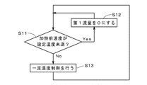
図3は、蒸気発生装置1の蒸気発生処理における熱媒混合部34の動作の流れを示す図である。熱媒混合部34では、蒸気発生処理中、図1の温度センサ342により熱媒油の加熱前温度の測定値が、所定の時間間隔にて繰り返し取得され、図3の動作が常時行われる。以下、熱媒混合部34の動作に注目しつつ、蒸気発生装置1における蒸気発生処理について説明する。
蒸気発生処理では、ポンプ32の駆動により熱媒タンク30から一定の流量にて熱媒油が連続的に送液される。また、熱媒混合部34では、熱媒油の加熱前温度(の測定値)が、設定温度未満であるか否かが所定の時間間隔にて確認される。ここで、設定温度は、蒸気発生器31において設定圧力の蒸気を発生させることが可能な最低の温度(例えば200℃)である。設定温度は、蒸気発生器31において発生する蒸気の用途等に応じて任意に決定されてよい。
例えば、日の出と同時に蒸気発生装置1の駆動が開始された直後では、熱媒油の加熱前温度が設定温度未満であり(ステップS11)、この場合、流量調整弁341により熱媒油の第1流量が0とされる(ステップS12)。すなわち、熱媒タンク30からポンプ32により送液される全ての熱媒油が、バイパス流路340を流れる。第1流量が既に0である場合には、ステップS12では、この状態が維持される。バイパス流路340を通過した熱媒油は、循環経路33に沿って太陽光集光装置2に流入する。循環経路33は主に断熱管により形成されるため、バイパス流路340を通過した熱媒油は、温度がほとんど低下することなく、太陽光集光装置2に流入する。
このとき、蒸気発生器31に熱媒油が供給されないため、蒸気発生器31の内部圧力(の測定値)は設定圧力未満である。圧力調整部42では、内部圧力が設定圧力未満である場合には、圧力制御弁421が閉状態とされ、蒸気発生器31から外部設備9に蒸気は供給されない。外部設備9では、補助ボイラ91を利用して必要な量の蒸気が生成される。これにより、蒸気発生装置1からの蒸気の供給流量が0である間における外部設備9の稼働が可能となる。なお、蒸気供給路41には逆止弁が設けられており、補助ボイラ91からの蒸気が蒸気供給路41を逆流することはない。
バイパス流路340を利用して太陽光集光装置2および熱媒タンク30を循環する熱媒油の温度は、太陽光集光装置2による加熱により漸次上昇する。熱媒油の加熱前温度が設定温度以上となると(ステップS11)、熱媒混合部34では、熱媒油の加熱前温度が設定温度を維持するように、流量調整弁341を調整する一定温度制御が開始される(ステップS13)。一定温度制御では、熱媒油の第1流量を0よりも大きくして蒸気発生器31への熱媒油の供給を確保しつつ、第1流量と第2流量との比を温度センサ342の測定値に基づいて変更することにより、熱媒油の加熱前温度がおよそ設定温度に保たれる。例えば、熱媒油の加熱前温度が設定温度よりもある程度高い場合には、第1流量が増大され、第2流量が低減される。また、熱媒油の加熱前温度が設定温度よりもある程度低い場合には、第2流量が増大され、第1流量が低減される。なお、一定温度制御が開始されると、熱媒油の加熱前温度が設定温度未満である状態が、予め定められた継続解除時間以上続かない限り、一定温度制御が継続される(後述の圧力調整部42による定圧制御において同様)。
蒸気発生器31では、内部に配置された伝熱管を熱媒油が流れることにより、内部に貯溜される水が加熱され、蒸気が発生する。換言すると、熱媒油の熱が蒸気発生器31において放熱される。蒸気発生器31の内部圧力が設定圧力以上となると、圧力制御弁421がゆっくりと開かれ、内部圧力がおよそ設定圧力に保たれるように圧力制御弁421の開度が調整される。すなわち、圧力調整部42による内部圧力の定圧制御が開始される。定圧制御では、蒸気発生器31内の蒸気(飽和蒸気)が、圧力制御弁421の開度に応じた供給流量にて蒸気供給路41を流れ、外部設備9に供給される。外部設備9では、補助ボイラ91を利用して、外部設備9において不足する蒸気が補充される。
日射量が多くなるに従って、太陽光集光装置2から熱媒タンク30に流入する熱媒油の温度が漸次上昇する。熱媒混合部34では、第1流量を増大し、第2流量を低減することにより、熱媒油の加熱前温度の一定温度制御が行われる。蒸気発生器31では、第1流量の増大に従って蒸気の発生量(単位時間当たりの発生量)が多くなり、圧力制御弁421の開度および外部設備9への蒸気の供給流量も漸次増大する。このとき、外部設備9において一定量の蒸気を利用する場合には、補助ボイラ91にて生成する蒸気の量が漸次低減される。
本実施の形態における蒸気発生器31では、熱媒タンク30に貯溜される熱媒油の温度が、想定される最高の温度(例えば、熱媒油の使用上限近傍である340℃であり、以下、「使用最高温度」という。)よりも低い温度、例えば約250℃となる際に、第2流量が0となる。すなわち、熱媒タンク30からポンプ32により送液される全ての熱媒油が、蒸気発生器31に供給される。熱媒タンク30に貯溜される熱媒油の温度が、使用最高温度まで上昇すると、蒸気発生器31における蒸気の発生量(および、給水タンク51からの給水量)が最大となる。熱媒タンク30内の熱媒油の温度が、使用最高温度となることにより、使用最高温度と設定温度との差(ここでは、140℃)に相当する量の蓄熱が実質的に完了する。
例えば、太陽光が雲等により遮られ、日射量が少なくなると、太陽光集光装置2から熱媒タンク30に流入する熱媒油の温度が漸次低下し、熱媒タンク30に貯溜される熱媒油の温度も使用最高温度から低下する。熱媒油の加熱前温度が(一時的に)設定温度未満となると、一定温度制御として、第1流量が低減され、第2流量が増大される。日射量が少ない状態においても、熱媒タンク30に貯溜される高温の熱媒油により、熱媒油の加熱前温度が、暫くの間、設定温度近傍に保たれる(熱媒タンク30における放熱と捉えることができる。)。また、第1流量は0とはならず、蒸気発生器31から外部設備9への蒸気の供給は継続される。もちろん、第1流量の低減に従って蒸気発生器31の蒸気の発生量は少なくなり、圧力制御弁421の開度および外部設備9への蒸気の供給流量も漸次減少する。このとき、外部設備9において一定量の蒸気を利用する場合には、補助ボイラ91にて生成する蒸気の量が漸次増大される。
日射量が少ない状態が長くなると、熱媒タンク30に貯溜される熱媒油の温度は、設定温度近傍まで漸次低下する。そして、熱媒油の加熱前温度が設定温度未満である状態が継続解除時間以上続くと(ステップS11)、熱媒油の第1流量が0とされる(ステップS12)。また、圧力制御弁421が最小開度の状態でも蒸気発生器31の内部圧力が設定圧力未満となると、圧力制御弁421がゆっくりと閉じられて、閉状態となる。これにより、蒸気発生装置1から外部設備9への蒸気の供給流量が0となる。
既述のように、蒸気発生装置1では、日射量がほとんど無い状態となっても、熱媒タンク30における蓄熱により蒸気の供給を、ある程度の時間継続することが可能である。したがって、この間に、補助ボイラ91の出力を漸次増大させることにより、蒸気の供給流量が0となる際に、外部設備9において必要な量の蒸気を確保することが可能である。蒸気発生装置1では、日没により日射量が無くなると、ポンプ32の駆動が停止され、蒸気発生処理が終了する。
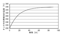
図4は、熱媒タンク30における蓄熱の際の熱媒油の温度変化を示す図であり、所定の演算により求めた結果を示している。図4の縦軸は熱媒タンク30内の熱媒油の温度を示し、横軸は時間を示す(後述の図5において同様)。ここでは、熱媒タンク30の容量を3000リットル、熱媒タンク30内の熱媒油の初期温度を200℃とし、340℃の熱媒油が太陽光集光装置2から毎秒2.78リットルの流量で熱媒タンク30内に流入する場合を示している。図4の例では、340℃の熱媒油の流入開始から50分で熱媒タンク30内の熱媒油の温度が約330℃となり、90分で熱媒油の温度が約340℃となる。実際には、熱媒タンク30内の熱媒油の温度上昇に伴って、蒸気発生器31における蒸気の発生量も多くなる。
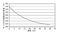
図5は、熱媒タンク30における放熱の際の熱媒油の温度変化を示す図であり、図4と同様に、演算により求めた結果を示している。ここでは、熱媒タンク30の容量を3000リットル、熱媒タンク30内の熱媒油の初期温度を340℃とし、設定温度である200℃の熱媒油が太陽光集光装置2から毎秒2.78リットルの流量で熱媒タンク30内に流入する場合を示している。図5の例では、200℃の熱媒油の流入開始から40分で熱媒タンク30内の熱媒油の温度が約215℃となる。既述のように、蒸気発生器31に供給される熱媒油の温度が200℃以上である場合に、蒸気発生器31において設定圧力の蒸気を発生させることが可能である。したがって、熱媒タンク30内の熱媒油の温度が200℃以上である状態が維持されている間(少なくとも40分の間)では、蒸気発生器31における蒸気の発生が可能となる。なお、熱媒タンク30内の熱媒油の温度低下に伴って、蒸気発生器31における蒸気の発生量も少なくなる。
以上に説明したように、蒸気発生装置1では、循環経路33における熱媒タンク30と蒸気発生器31との間の分岐位置と、蒸気発生器31と太陽光集光装置2との間の合流位置344とを接続するバイパス流路340が設けられる。そして、蒸気発生器31を通過した熱媒油が、バイパス流路340を通過した熱媒油と混合されて太陽光集光装置2へと送られる。これにより、日射量が多い場合に、蒸気発生器31から蒸気を外部設備9に供給しつつ、熱媒タンク30内の熱媒油の温度を短時間に上昇させて、顕熱として蓄熱することが可能となる。また、日射量が少ない場合にも、熱媒タンク30内の高温の熱媒油を利用して、ある程度の期間、蒸気を外部設備9に継続して供給することができる。その結果、蒸気発生装置1では、簡易な構造により、日射量の変化による蒸気の供給流量の急激な変動(主として低下)を防止する、すなわち、外部設備9への蒸気の供給流量を緩やかに変化させることができる。
熱媒混合部34では、流量調整部である流量調整弁341が設けられるとともに、温度センサ342により、合流位置344から太陽光集光装置2に向かう熱媒油の温度が測定される。そして、温度センサ342の測定値が設定温度となるように、分岐位置から蒸気発生器31に流れる熱媒油の第1流量と、バイパス流路340を流れる熱媒油の第2流量とが、流量調整弁341により調整される。これにより、日射量が十分にある場合に、熱媒タンク30にて継続して蓄熱しつつ、第1流量を増大して蒸気を比較的高い供給流量にて外部設備9に供給することができる。また、日射量が少ない場合に、第1流量を低減することにより(蒸気発生器31による蒸気の供給流量は低くなる。)、蒸気を外部設備9に継続して供給可能となる期間を長くすることができる。
図6は、比較例の蒸気発生装置8の一部を示す図である。比較例の蒸気発生装置8では、熱媒油が、太陽光集光装置81、高温熱媒タンク82、蒸気発生器83、および、低温熱媒タンク84を順に循環する。また、太陽光集光装置81と高温熱媒タンク82との間には、三方弁85が設けられ、三方弁85と低温熱媒タンク84とがバイパス流路86により接続される。比較例の蒸気発生装置8では、太陽光集光装置81により340℃に加熱された熱媒油が高温熱媒タンク82において貯溜され、340℃の熱媒油が蒸気発生器83に供給される。蒸気発生器83にて放熱した熱媒油は低温熱媒タンク84に貯溜され、低温熱媒タンク84内の熱媒油が太陽光集光装置81に送られて太陽光の集光により加熱される。
ここで、比較例の蒸気発生装置8では、日射量が少ない場合等に、太陽光集光装置81を通過した熱媒油の温度が340℃よりも低いときには、バイパス流路86を介して熱媒油が低温熱媒タンク84に戻される。これにより、高温熱媒タンク82内の熱媒油の温度が340℃近傍にて維持される。高温熱媒タンク82内の熱媒油は、一定温度かつ一定流量にて蒸気発生器83に供給される。したがって、日射量が少ない状態が長くなると、高温熱媒タンク82内の熱媒油がなくなり、蒸気発生器83において水の蒸気の発生が突然停止する(すなわち、蒸気の発生量が急激に0まで低下する。)。
これに対し、蒸気発生装置1では、日射量が少ない状態において、一部の熱媒油がバイパス流路340を流れて蒸気発生器31にて消費される熱量が制限されることにより、外部設備9への蒸気の供給流量を緩やかに変化させることができる。また、蒸気発生装置1では、太陽光集光装置2を通過した熱媒油の温度が、熱媒タンク30内の熱媒油の温度よりも低い場合でも、太陽光集光装置2からの全ての熱媒油が熱媒タンク30内に流入する。このように、熱媒タンク30内の熱媒油の温度の低下(変動)を許容することにより、比較例の蒸気発生装置8における低温熱媒タンク84を省略することができる。さらに、熱媒タンク30が、循環経路33における熱媒用の唯一のタンクであることにより、比較例の蒸気発生装置8に比べて、熱媒油の使用量を少なくするとともに、蒸気発生装置1の構成を簡素化することができる。
ところで、外部設備9において、燃料により蒸気を発生させる補助ボイラ91が設けられるが、補助ボイラ91では、蒸気の発生量を急激に変化させることは困難である。しかしながら、蒸気発生装置1では、既述のように外部設備9への蒸気の供給流量を緩やかに変化させることができるため、外部設備9において、蒸気発生装置1および補助ボイラ91による一定量の蒸気を安定して利用することができる。
上記蒸気発生装置1では様々な変形が可能である。
流量調整部は、三方弁である流量調整弁341以外により実現されてもよい。例えば、分岐位置と蒸気発生器31との間に設けられる二方弁と、バイパス流路340に設けられる二方弁との組合せが流量調整部として設けられ、第1流量と第2流量とが調整されてもよい。また、蒸気発生装置1の設計によっては、流量調整部が省略されてもよい。例えば、循環経路33における熱媒タンク30と蒸気発生器31との間の分岐位置と、蒸気発生器31と太陽光集光装置2との間の合流位置344とを接続するバイパス流路340のみが、熱媒混合部34として設けられる。この場合も、日射量が多い場合に、蒸気発生器31において蒸気を発生しつつ、熱媒タンク30内の熱媒油の温度を短時間に上昇させて蓄熱することができ、日射量が少ない場合にも、熱媒タンク30内の高温の熱媒油を利用して、ある程度の期間、蒸気を外部設備9に継続して供給することができる。
熱媒タンク30内の熱媒油の温度を測定する温度センサが設けられ、当該温度センサの測定値に基づいて流量調整部が制御されてもよい。また、循環経路33において、太陽光集光装置2と熱媒タンク30との間に設けられる温度センサ336の測定値に基づいて流量調整部が制御されてもよい。熱媒混合部34では、温度センサが、循環経路33におけるいずれかの位置における熱媒油の温度を測定し、当該温度センサの測定値に基づいて流量調整部を制御することにより、第1流量および第2流量を適切に調整することが可能である。
熱媒タンク30において貯溜される熱媒は、熱媒油以外に、溶融塩等であってもよい。上記実施の形態では、蒸気発生器31において水が貯溜されるが、例えば、アンモニア等の他の液体が蒸気発生器31において貯溜されてもよい。
太陽光を利用する蒸気発生装置1は、海水淡水化(造水)以外に、製塩や酒造等の様々な用途に利用することが可能である。蒸気発生装置1は、ボイラを有する様々な設備に追加することが可能であり、これにより、当該ボイラ(補助ボイラ)にて消費される燃料を削減することができる。もちろん、蒸気発生装置1が発電に利用されてもよい。
上記実施の形態および各変形例における構成は、相互に矛盾しない限り適宜組み合わされてよい。
発明を詳細に描写して説明したが、既述の説明は例示的であって限定的なものではない。したがって、本発明の範囲を逸脱しない限り、多数の変形や態様が可能であるといえる。
1 蒸気発生装置
2 太陽光集光装置
9 外部設備
30 熱媒タンク
31 蒸気発生器
32 ポンプ
33 循環経路
34 熱媒混合部
91 補助ボイラ
340 バイパス流路
341 流量調整弁
342 温度センサ
344 合流位置
2 太陽光集光装置
9 外部設備
30 熱媒タンク
31 蒸気発生器
32 ポンプ
33 循環経路
34 熱媒混合部
91 補助ボイラ
340 バイパス流路
341 流量調整弁
342 温度センサ
344 合流位置
Claims (6)
- 太陽光を利用する蒸気発生装置であって、
集光させた太陽光により熱媒を加熱する太陽光集光装置と、
前記熱媒を貯溜する熱媒タンクと、
液体を貯溜し、前記熱媒を利用して前記液体を加熱することにより、前記液体の蒸気を発生させる蒸気発生器と、
前記熱媒タンクから前記蒸気発生器および前記太陽光集光装置を順に経由して前記熱媒タンクに戻る循環経路に沿って前記熱媒を連続的に循環させるポンプと、
前記循環経路における前記熱媒タンクと前記蒸気発生器との間の分岐位置と、前記蒸気発生器と前記太陽光集光装置との間の合流位置とを接続するバイパス流路を有し、前記蒸気発生器を通過した前記熱媒を、前記バイパス流路を通過した前記熱媒と混合して前記太陽光集光装置へと送る熱媒混合部と、
を備える。 - 請求項1に記載の蒸気発生装置であって、
前記熱媒混合部が、
前記循環経路における前記熱媒の温度を測定する温度センサと、
前記分岐位置から前記蒸気発生器に流れる前記熱媒の第1流量と、前記バイパス流路を流れる前記熱媒の第2流量とを、前記温度センサの測定値に基づいて調整する流量調整部と、
をさらに備える。 - 請求項2に記載の蒸気発生装置であって、
前記温度センサが、前記合流位置から前記太陽光集光装置に向かう前記熱媒の温度を測定し、
前記流量調整部が、前記温度センサの測定値が所定の温度となるように、前記第1流量と前記第2流量とを調整する。 - 請求項1ないし3のいずれかに記載の蒸気発生装置であって、
前記太陽光集光装置を通過した前記熱媒の温度が、前記熱媒タンク内の前記熱媒の温度よりも低い場合でも、前記太陽光集光装置から前記熱媒タンク内に前記熱媒が流入する。 - 請求項1ないし4のいずれかに記載の蒸気発生装置であって、
前記熱媒タンクが、前記循環経路における前記熱媒用の唯一のタンクである。 - 請求項1ないし5のいずれかに記載の蒸気発生装置であって、
前記蒸気発生器にて発生した前記蒸気が供給される外部設備において、燃料により蒸気を発生させる補助ボイラが設けられている。
Applications Claiming Priority (2)
| Application Number | Priority Date | Filing Date | Title |
|---|---|---|---|
| JP2015192596A JP2017067360A (ja) | 2015-09-30 | 2015-09-30 | 蒸気発生装置 |
| JP2015-192596 | 2015-09-30 |
Publications (1)
| Publication Number | Publication Date |
|---|---|
| WO2017057261A1 true WO2017057261A1 (ja) | 2017-04-06 |
Family
ID=58423808
Family Applications (1)
| Application Number | Title | Priority Date | Filing Date |
|---|---|---|---|
| PCT/JP2016/078240 Ceased WO2017057261A1 (ja) | 2015-09-30 | 2016-09-26 | 蒸気発生装置 |
Country Status (2)
| Country | Link |
|---|---|
| JP (1) | JP2017067360A (ja) |
| WO (1) | WO2017057261A1 (ja) |
Cited By (1)
| Publication number | Priority date | Publication date | Assignee | Title |
|---|---|---|---|---|
| CN114306656A (zh) * | 2021-12-23 | 2022-04-12 | 中国矿业大学 | 一种太阳能灭菌系统 |
Families Citing this family (1)
| Publication number | Priority date | Publication date | Assignee | Title |
|---|---|---|---|---|
| CN108317577A (zh) * | 2018-03-26 | 2018-07-24 | 常州绿资环保设备有限公司 | 余汽、余热回收再利用系统 |
Citations (4)
| Publication number | Priority date | Publication date | Assignee | Title |
|---|---|---|---|---|
| US20110108020A1 (en) * | 2009-11-11 | 2011-05-12 | Mcenerney Bryan William | Ballast member for reducing active volume of a vessel |
| US20110297206A1 (en) * | 2010-06-08 | 2011-12-08 | Timothy Devine | Concentrated solar power receiver maintenance system |
| EP2574784A2 (en) * | 2011-09-29 | 2013-04-03 | Pratt & Whitney Rocketdyne Inc. | Solar power system and method therefor |
| US20140033708A1 (en) * | 2011-04-19 | 2014-02-06 | Siemens Aktiengesellschaft | Solar thermal power plant and method for operating a solar thermal power plant |
-
2015
- 2015-09-30 JP JP2015192596A patent/JP2017067360A/ja active Pending
-
2016
- 2016-09-26 WO PCT/JP2016/078240 patent/WO2017057261A1/ja not_active Ceased
Patent Citations (4)
| Publication number | Priority date | Publication date | Assignee | Title |
|---|---|---|---|---|
| US20110108020A1 (en) * | 2009-11-11 | 2011-05-12 | Mcenerney Bryan William | Ballast member for reducing active volume of a vessel |
| US20110297206A1 (en) * | 2010-06-08 | 2011-12-08 | Timothy Devine | Concentrated solar power receiver maintenance system |
| US20140033708A1 (en) * | 2011-04-19 | 2014-02-06 | Siemens Aktiengesellschaft | Solar thermal power plant and method for operating a solar thermal power plant |
| EP2574784A2 (en) * | 2011-09-29 | 2013-04-03 | Pratt & Whitney Rocketdyne Inc. | Solar power system and method therefor |
Cited By (2)
| Publication number | Priority date | Publication date | Assignee | Title |
|---|---|---|---|---|
| CN114306656A (zh) * | 2021-12-23 | 2022-04-12 | 中国矿业大学 | 一种太阳能灭菌系统 |
| CN114306656B (zh) * | 2021-12-23 | 2023-07-28 | 中国矿业大学 | 一种太阳能灭菌系统 |
Also Published As
| Publication number | Publication date |
|---|---|
| JP2017067360A (ja) | 2017-04-06 |
Similar Documents
| Publication | Publication Date | Title |
|---|---|---|
| US20130285380A1 (en) | Thermal storage system and methods | |
| CN103375926B (zh) | 太阳能系统和操作方法 | |
| US8607567B2 (en) | Solar steam generator | |
| US20130307273A1 (en) | Solar energy storage system including three or more reservoirs | |
| CN102146899B (zh) | 多塔式二元工质太阳能高温热发电系统 | |
| US20130086904A1 (en) | Solar Thermal Power Plant | |
| US20090260622A1 (en) | Solar steam generator having a standby heat supply system | |
| CN103511208A (zh) | 一种可在全参数范围内变负荷运行的熔盐蒸汽发生系统 | |
| WO2014148259A1 (ja) | 太陽熱集熱システム | |
| CN102828925B (zh) | 一种二元工质塔式太阳能发电系统 | |
| CN105626402A (zh) | 熔融盐储热太阳能热发电系统 | |
| CN103403468A (zh) | 热能生成系统 | |
| WO2013098945A1 (ja) | 太陽熱発電設備 | |
| CN102326025A (zh) | 用于太阳能热电站的供水脱气器 | |
| WO2017057261A1 (ja) | 蒸気発生装置 | |
| KR102096691B1 (ko) | 탑형 태양광 집중 설비의 보일러 내 건조를 방지하기 위한 방법 및 장치 | |
| US20150082792A1 (en) | Solar and renewable/waste energy powered turbine with two stage heating and graphite body heat exchanger | |
| CN205744023U (zh) | 高温高压水蓄能蒸汽发电系统 | |
| JP2015161284A (ja) | 制御システムおよび熱供給方法 | |
| WO2017077766A1 (ja) | 太陽熱集熱システムおよびその運転方法 | |
| KR20140079874A (ko) | 태양 에너지와 외부 스팀의 상보적 발전 장치 | |
| JP2017067359A (ja) | 蒸気発生装置 | |
| CN104359093A (zh) | 一种太阳能直接蒸汽产生系统 | |
| CN204477990U (zh) | 一种太阳能直接蒸汽产生系统 | |
| US20120080027A1 (en) | Solar receiver with natural circulation for generating saturated steam |
Legal Events
| Date | Code | Title | Description |
|---|---|---|---|
| 121 | Ep: the epo has been informed by wipo that ep was designated in this application |
Ref document number: 16851432 Country of ref document: EP Kind code of ref document: A1 |
|
| NENP | Non-entry into the national phase |
Ref country code: DE |
|
| 122 | Ep: pct application non-entry in european phase |
Ref document number: 16851432 Country of ref document: EP Kind code of ref document: A1 |