WO2017057191A1 - 再圧縮蒸気の利用方法及びプラント - Google Patents
再圧縮蒸気の利用方法及びプラント Download PDFInfo
- Publication number
- WO2017057191A1 WO2017057191A1 PCT/JP2016/078059 JP2016078059W WO2017057191A1 WO 2017057191 A1 WO2017057191 A1 WO 2017057191A1 JP 2016078059 W JP2016078059 W JP 2016078059W WO 2017057191 A1 WO2017057191 A1 WO 2017057191A1
- Authority
- WO
- WIPO (PCT)
- Prior art keywords
- steam
- gas
- compressor
- flow rate
- condensable gas
- Prior art date
- Legal status (The legal status is an assumption and is not a legal conclusion. Google has not performed a legal analysis and makes no representation as to the accuracy of the status listed.)
- Ceased
Links
Images

Classifications
-
- B—PERFORMING OPERATIONS; TRANSPORTING
- B01—PHYSICAL OR CHEMICAL PROCESSES OR APPARATUS IN GENERAL
- B01D—SEPARATION
- B01D1/00—Evaporating
- B01D1/28—Evaporating with vapour compression
-
- B—PERFORMING OPERATIONS; TRANSPORTING
- B01—PHYSICAL OR CHEMICAL PROCESSES OR APPARATUS IN GENERAL
- B01D—SEPARATION
- B01D3/00—Distillation or related exchange processes in which liquids are contacted with gaseous media, e.g. stripping
- B01D3/14—Fractional distillation or use of a fractionation or rectification column
-
- B—PERFORMING OPERATIONS; TRANSPORTING
- B01—PHYSICAL OR CHEMICAL PROCESSES OR APPARATUS IN GENERAL
- B01D—SEPARATION
- B01D3/00—Distillation or related exchange processes in which liquids are contacted with gaseous media, e.g. stripping
- B01D3/14—Fractional distillation or use of a fractionation or rectification column
- B01D3/32—Other features of fractionating columns ; Constructional details of fractionating columns not provided for in groups B01D3/16 - B01D3/30
-
- B—PERFORMING OPERATIONS; TRANSPORTING
- B01—PHYSICAL OR CHEMICAL PROCESSES OR APPARATUS IN GENERAL
- B01D—SEPARATION
- B01D5/00—Condensation of vapours; Recovering volatile solvents by condensation
Definitions
- the present invention relates to a method for efficiently using recompressed steam obtained by adiabatically compressing this steam as a heat source in a process involving generation of steam, and a plant using this method.
- the generated process steam is the target product (for example, a compound that is liquid at normal temperature and pressure), or the process steam is atmospheric If the discharge into it contains substances that are not suitable, a process is usually introduced in which the process vapor is cooled and condensed and recovered.
- the target product for example, a compound that is liquid at normal temperature and pressure
- the process steam is atmospheric If the discharge into it contains substances that are not suitable, a process is usually introduced in which the process vapor is cooled and condensed and recovered.
- VRC vapor recompression
- Patent Document 1 discloses a method for recovering a solvent and a solute from a stock solution containing a volatile solvent and a low concentration non-volatile solute by a heat pump method (vapor recompression method). Is disclosed. Specifically, by introducing the process steam generated in the distillation tower or the like into the steam compressor from the tower top line, compressing and heating, and supplying this compressed process steam (recompressed steam) to the reboiler in a necessary amount, It is used as a heat source at the bottom of the tower.
- vapor recompression method vapor recompression method
- Patent Document 2 describes gas components such as uncondensed recompressed steam existing downstream of the compressor in the VRC system.
- a method of using process steam while preventing damage to equipment such as a compressor by providing a circulation step for returning the gas to the main step is disclosed.
- the stagnation of the gas component downstream of the compressor can be suppressed by the circulation step, so that the process steam can be used safely and easily.
- pressure control on the downstream side of the compressor is not easy, and recompression may not be performed smoothly, leaving room for improvement in improving the energy saving effect.
- the degree of freedom in process design of each unit and its layout has been limited.
- an object of the present invention is to provide a method of efficiently using process steam (recompressed steam) heated by adiabatic compression as a heat source, and a plant using this method.
- Another object of the present invention is to provide a method capable of smoothly recompressing process steam and a plant using this method.
- Still another object of the present invention is to provide a method capable of smoothly operating a plant equipped with a VRC system even if the entire amount of the recompressed steam (the total amount of condensable gas components) is condensed, and a plant using this method. It is to provide.
- Another object of the present invention is to provide a process steam utilization method having excellent process design flexibility in the VRC system, and a plant using this method.
- Still another object of the present invention is to provide a method for safely and simply using the recompressed steam as a heat source, and a plant using this method.
- the present inventors generate process vapor containing a condensable gas component, and recover the condensable gas component (or condensable component) of the generated process vapor as a condensate.
- a main compression step a recompression step in which at least a part of the process steam is adiabatically compressed by a compressor to raise the temperature to obtain the recompression steam, a heat exchange step using the recompression steam as a heat source, and heat exchange
- a method of using recompressed steam including a recirculating process for returning a gas component that has not been condensed among the recompressed steam used in the process to the main process, if non-condensable gas is introduced downstream of the compressor,
- the present invention has been completed by finding a process that can achieve a higher energy saving effect while preventing a decrease in pressure and that can be stably operated.
- the recompressed steam utilization method of the present invention generates a process steam containing a condensable gas component, and recovers the condensable gas component (or condensable component) of the generated process steam as a condensate.
- a recompression process in which at least a part of the process steam is adiabatically compressed by a compressor to raise the temperature to obtain recompressed steam, a heat exchange process using the recompressed steam as a heat source, and a heat exchange process.
- a method for using the recompressed steam including a circulation process for returning the gas component that has not been condensed to the main process, and a gas introduction process for introducing a non-condensable gas downstream of the compressor.
- the non-condensable gas may include a gas capable of maintaining a gaseous state under the temperature and pressure on the back pressure side of the compressor, and may include, for example, an inert gas such as nitrogen.
- you may control the compression ratio in the said recompression process by adjusting the flow volume of the non-condensable gas in a gas introduction process, and the flow volume of the gas component returned to the main process in a circulation process.
- Non-condensable gas may be introduced in the circulation process. Furthermore, the introduction flow rate of the non-condensable gas may be 0.01 to 3% by volume with respect to the flow rate of the process steam generated in the main process. Moreover, the utilization method of the recompressed steam of this invention may further include the gas-liquid separation process for carrying out gas-liquid separation of the process fluid which passed through the heat exchange process.
- the present invention also includes a steam generator for generating process steam containing a condensable gas component, a main unit having a condenser for cooling and condensing a part of the generated process steam, and the remainder of the process steam.
- a steam generator for generating process steam containing a condensable gas component
- a main unit having a condenser for cooling and condensing a part of the generated process steam, and the remainder of the process steam.
- the heat recompression unit for using the recompressed steam as a heat source
- the recompressed steam provided to the heat exchange unit.
- a recompressed steam utilization plant having a circulation line for returning the uncondensed gas components to the main unit, comprising a gas introduction unit for introducing non-condensable gas downstream of the compressor Also includes a plant using recompressed steam.
- the non-condensable gas may include a gas capable of maintaining a gaseous state under the temperature and pressure on the back pressure side of the compressor, and may include, for example, an inert gas such as nitrogen. .
- a flow rate control unit capable of adjusting the introduction flow rate of the non-condensable gas and the flow rate of the gas component returning to the main unit may be provided.
- the gas introduction unit may be connected upstream of the flow rate control unit of the circulation line.
- the gas introduction unit is provided with a flow rate control unit that can be adjusted so that the introduction flow rate of the non-condensable gas is 0.01 to 3% by volume with respect to the flow rate of the process steam generated in the main process. Also good.
- process steam means steam generated in a manufacturing process (step) in which a unit operation involving a gas-liquid phase change is incorporated, and “recompressed steam”.
- VRC method vapor recompression method
- non-condensable gas means under the temperature and pressure in the back pressure space of the compressor.
- the non-condensable gas is introduced downstream of the compressor in the VRC system, so that the pressure (back pressure) necessary for effectively functioning (or operating) the VRC system can be maintained. It becomes possible. Therefore, since a large amount of recompressed steam (for example, the total amount of recompressed steam) can be effectively condensed, the energy saving effect obtained by the VRC method can be significantly improved. Moreover, since the pressure in the downstream (back pressure space) of the compressor can be easily controlled by introducing the non-condensable gas, the operation of the plant equipped with the VRC method can be performed smoothly. Therefore, it is possible to provide a method of using process steam that can be applied to a plant with large fluctuations in throughput and operating conditions and that has excellent process design flexibility. In addition, since it includes the circulation process which returns the gas component which was not condensed by heat exchange etc. to the main process (main process), recompressed steam can be utilized safely and simply, without damaging an apparatus.
- a large amount of recompressed steam for example, the total amount of
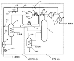
- FIG. 1 is a process flow diagram for explaining an example of a utilization method and plant (apparatus) of recompressed steam according to the present invention.
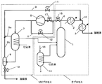
- FIG. 2 is a process flow chart for explaining the utilization method and plant (apparatus) of recompressed steam according to the first embodiment.
- FIG. 3 is a process flow diagram for explaining the utilization method and plant (apparatus) of the recompressed steam of Comparative Example 1.
- the recompressed steam utilization plant includes a distillation column (or distiller) 1 as a process steam generator for discharging process steam containing a condensable gas component.
- a discharge line for discharging the steam branches at the branching section 4.
- One of the branched lines is provided with a first condenser 2 and a second condenser 3 for cooling and condensing a part of the process steam discharged from the distillation column 1, and the condensability in the process steam is provided.
- the gas component (condensable component) is cooled by condensers 2 and 3 and recovered as a condensate.
- the main unit includes the distillation column 1, the first condenser 2 and the second condenser 3.
- the remainder of the process steam is adiabatically compressed through a line in which flow rate control valves (valves) 15 and 17 as flow rate control units are arranged, and the temperature is increased to restart.
- a turbo compressor 5 as a steam recompression unit for obtaining compressed steam
- a heat exchanger 7 as a heat exchange unit for using the recompressed steam as a heat source
- a process fluid passing through the heat exchanger 7 are gasified.
- a gas-liquid separator 8 is disposed as a gas-liquid separation unit for liquid separation and returning the separated gas components to the main unit.
- the process fluid that has passed through the heat exchanger 7 is further separated into a gas component and a liquid component (condensate), and the separated condensate is a flow rate control valve 13 as a flow rate control unit.
- the gas component separated by the gas-liquid separator 8 passes from the air ring line (or pressure equalizing pipe) 9a of the heat exchanger 7 through the air ring line (or pressure equalizing pipe) 9b of the gas-liquid separator 8.
- the first gas is returned to the main unit by the first circulation line 9.
- the first circulation line 9 is connected to a line between the first condenser 2 and the second condenser 3 via a connection part (or a pipe connection part) 10 and passes through the first condenser 2.
- the process fluid (process vapor) is combined, cooled by the second condenser 3, condensed and recovered.
- the turbo compressor 5 is provided with a second circulation line 6 for connecting the inlet side line and the outlet side line of the compressor, and a flow rate control valve 12 as a flow rate control unit. Also good.
- the second circulation line 6 may be connected to a line between the flow control valves 15 and 17 on the line on the inlet side of the compressor.
- the utilization method or plant of the present invention includes a distillation column 1, a first condenser 2, and a second condenser 3 as necessary, generates process steam containing a condensable gas component, cools and condenses.
- Main process main process
- turbo-type compressor 5 turbo-type compressor 5
- heat exchanger 7 heat exchanger 7
- gas-liquid separator 8 turbo-type compressor 5
- the process steam is adiabatically compressed by the compressor to generate recompressed steam whose temperature is increased. It is divided into a VRC process (VRC process) used as a heat source.
- VRC process used as a heat source.
- the flow control valve 17 is adjusted to a predetermined opening degree (if the discharge pressure of the turbo compressor 5 becomes too low, the opening degree of the flow control valves 11 and / or 12 is adjusted to the flow amount as necessary. After adjusting the amount of process steam introduced into the compressor (adjusted in a decreasing direction), the turbo compressor 5 is started and stabilized at the rated rotational speed.
- the process steam passing through the turbo-type compressor 5 is hardly loaded with a discharge pressure, but a process in which heat of the compressor shaft power ⁇ mechanical efficiency ⁇ (1 ⁇ adiabatic efficiency) passes through the compressor.
- the flow control valve 12 When the flow control valve 12 is in an open state, it is closed so that the process steam flowing through the VRC process basically passes through the compressor only once. Therefore, the temperature rise is only the heat transfer from the compressor, and the temperature rise width is small. Since the temperature difference between the process steam that has passed through the turbo compressor 5 and the boiling point of the internal process of the heat exchanger 7 is not sufficient, heat transfer is insufficient and condensation does not occur much.
- the process steam (condensable gas component in the process steam) is returned to the pipe connection portion 10 of the main process through the first circulation line 9 without being condensed, and is recovered by cooling condensation.
- the uncondensed steam can be returned to the main process by the first circulation line in the VRC process in this way, it is possible to suppress stagnation of process steam due to heat transfer failure in the heat exchange unit. Further, it is possible to prevent the compressor from being damaged due to the stagnation of the gas flow in the compressor.
- the second circulation line 6 may be used to secure a circulation flow rate in order to avoid surging in an emergency in addition to controlling the process steam circulation method. Good.
- the flow rate control valve 13 can open the condensate at an appropriate degree of opening or frequency after confirming the liquid level of the condensate in the gas-liquid separator 8 and can send the condensate to a subsequent process.
- the condensable gas component of the recompressed steam in the heat exchange process and the like and the process condensate of non-condensable gas such as seal gas that leaks into the process from the bearing of the compressor (condensable) Due to the dissolution of the gas component in the condensate), the pressure (or back pressure on the downstream side of the compressor) decreases (or stagnation of pressure increase) and the accompanying temperature decrease (or stagnation of temperature increase). Occur.
- the predetermined pressure may not be maintained (or maintained), and in order to maintain the predetermined pressure, the heat exchange step
- the amount of condensation of condensable gas components in (or the amount of raw material charged in the heat exchanger (VRC evaporator)) must be limited. Therefore, the pressure control on the downstream side of the compressor is not easy, and the energy saving effect is reduced.
- the pressure drop or stagnation of pressure rise
- the compressor is idle (the state where the compressor is simply blowing without being compressed)
- the plant (or recompression) equipped with the VRC system The unit (or process)) cannot be smoothly operated, and the function (or operation) as an inherent energy saving plant may be stopped. Therefore, in addition to adjusting the opening degree of the flow control valve 11, the pressure (or back pressure on the downstream side of the compressor) is adjusted by adjusting the opening degree of the flow control valve 18 and introducing the non-condensable gas from the gas introduction line 19. ) Is prevented and a predetermined pressure is maintained.
- the VRC method is effective even if a large amount of recompressed steam is condensed (for example, the condensable gas component is completely condensed) in the heat exchange step.
- a functioning process (or plant) can be designed (or easy), and the energy saving effect can be further improved.
- this gas introduction process (or unit) allows easy control of the pressure on the downstream side (back pressure space) of the compressor, and makes the plant (or recompression unit (or process)) equipped with the VRC system smooth ( (Or can be easily operated). For this reason, it is easy to apply to a plant with large fluctuations in throughput and operating conditions, and the process design is excellent in flexibility.
- the “back pressure space” means all spaces and lines (including an air ring line) that reach (or transmit) the discharge pressure of the compressor in the VRC process. That is, the “back pressure space” is a space and a line from the compressor downstream to the flow rate control unit, for example, from the downstream of the compressor via the heat exchange unit, the gas-liquid separation unit, etc. And a space and a line leading to the flow rate control unit disposed in each of the condensate discharge lines and a space and a line extending from the compressor downstream to the flow rate control unit disposed in the second circulation line. It means to include.
- non-condensable gases such as non-condensable gas introduced from the gas introduction line 19, recompressed vapor (non-condensed vapor) not condensed in the heat exchanger 7, seal gas not dissolved in the process condensate,
- the gas component is separated by the gas-liquid separator 8 and via the air ring line 9 b of the gas-liquid separator 8 and / or via the air ring line 9 a of the heat exchanger 7 and via the first circulation line 9. Returned to the main process.
- the condensable gas component contained in the steam returned to the connection part 10 (condensable gas component in the non-condensed steam) is usually cooled and condensed by the second condenser 3 on the downstream side of the connection part 10, Even if it flows into the compressor side (upstream side) for some reason, it is cooled and condensed by the first condenser 2. Therefore, even if it merges with the process steam discharged from the distillation column 1, the gas flow rate does not become excessive for the processes after the condensation process of the main process and the steam recompression process of the VRC process.
- the process steam generator is not limited to a distillation column as long as process steam is generated.
- the process steam generator is a device whose temperature is controlled by heating and evaporating with a heat source and then cooling and circulating. Specifically, it may be a reactor, an evaporator, a crystallizer, a dryer, or the like.
- a distillation column is preferred because the VRC process is easily incorporated into the heat source of the main process.
- the distillation tower is provided with a condenser for discharging process steam from the top of the tower, cooling and condensing the process steam, and a reboiler for vaporizing the condensate to be charged into the tower. You may use together with the reboiler of the said tower bottom by using an exchanger (VRC evaporator) as a heat source.
- VRC evaporator an exchanger
- the process steam only needs to contain at least a condensable gas component, and may contain a non-condensable gas component, which will be described later.
- a condensable gas component may contain a non-condensable gas component, which will be described later.
- it is difficult to contribute as a heat source and is economically disadvantageous.
- the condensable gas component contains water and / or an organic solvent.
- organic solvent examples include alcohols (alkyl alcohols such as ethanol, propanol and isopropanol, glycols such as ethylene glycol and propylene glycol), esters (methyl acetate, ethyl acetate, butyl acetate and the like), ketones ( Acetone, ethyl methyl ketone, methyl isobutyl ketone, cyclohexanone, etc.), aldehydes (acetaldehyde, propionaldehyde, etc.), carboxylic acids (acetic acid, propionic acid, etc.), ethers (chain ethers such as dimethyl ether and diethyl ether, dioxane, Cyclic ethers such as tetrahydrofuran), hydrocarbons (aliphatic hydrocarbons such as hexane, alicyclic hydrocarbons such as cyclohexane, aromatics such as benzene, toluene, xylene, etc.
- esters / hydrocarbons 99 / It may be mixed in a weight ratio of about 1 to 10/90, preferably 90/10 to 30/70, more preferably about 80/20 to 50/50.
- the boiling point of the organic solvent is determined by the type of the organic solvent, but is not particularly limited, and is, for example, about 30 to 150 ° C., preferably 50 to 120 ° C., more preferably about 60 to 100 ° C.
- the vapor pressure (25 ° C.) of the organic solvent is determined by the type of the organic solvent, but is not particularly limited, and is, for example, about 1 to 30 kPa, preferably 5 to 20 kPa, and more preferably about 10 to 15 kPa. .
- the proportion of the organic solvent can be selected according to the type of the organic solvent, and is not particularly limited, but may be 10% by weight or more with respect to the entire condensate of the process vapor, for example, 30 to 99% by weight, preferably May be about 50 to 98% by weight, more preferably about 80 to 95% by weight (especially 85 to 93% by weight).
- the temperature of the process vapor can be selected according to the type of condensable gas, and is not particularly limited, but is, for example, about 20 to 200 ° C., preferably 30 to 150 ° C., and more preferably about 50 to 100 ° C.
- the pressure of the process steam may be atmospheric pressure steam or pressurized steam.
- the flow rate of the process steam (discharge flow rate from the process steam generator) is, for example, about 0.1 to 100 m 3 / sec, preferably 1 to 50 m 3 / sec, and more preferably about 3 to 10 m 3 / sec.
- the condenser in the main process may be independent, but it is possible to efficiently condense the condensable gas component in the process steam and to suppress the circulation of uncondensed steam in the VRC process.
- two capacitors may be arranged in series.
- capacitance of a condenser is not specifically limited, Usually, the capacity
- the condenser is provided alone, the first circulation line is connected to the upstream side of the condenser.
- a plurality of capacitors When arranging a plurality of capacitors, a plurality of capacitors may be arranged in series, and the first circulation line may be connected upstream of the first capacitor, but downstream of the first capacitor, And a line upstream of the last capacitor (a line between adjacent capacitors, and when two capacitors are arranged in series, a line between the first capacitor and the second capacitor)
- 1 circulation line By connecting 1 circulation line, it can suppress that the condensable gas component in the non-condensed recompressed steam from the 1st circulation line circulates (backflows) to the VRC process.
- the plurality of condensers may be different condensers or the same condenser, but usually the first condenser (condensable gas in the process steam during steady operation only with the first condenser (upstream)).
- a condenser is used that has the capacity to condense all of the components.
- the main process may further include a heat exchanger such as a reboiler.
- the heat exchanger may be, for example, a main process evaporator for charging the raw material of the process steam generator in a gaseous state.
- the main process evaporator may be a column bottom reboiler, and a heat exchanger (such as a VRC evaporator) in the VRC process is used as a heat source for the main process together with the column bottom reboiler. May be used.
- the process steam discharge line in the main process branches into a main line for cooling and condensing the process steam by the condenser and a VRC line supplied to the VRC process.
- VRC line supplied to the VRC process flow control is performed.
- the unit is not essential, it is preferable to arrange a flow rate control unit for controlling the flow rate of the process steam to the VRC process upstream for stable operation of the plant. Normally, the flow rate control unit gradually increases the opening degree from the closed state at the start of operation, and is adjusted to a constant opening degree (for example, fully open) during steady operation where the VRC process is stable.
- the ratio of the process steam distributed between the main line and the VRC line can be appropriately selected according to the capacity of the compressor.
- the ratio supplied to the VRC line is larger. At times, the entire amount of process steam may be distributed to the VRC line, but usually some of the process steam is supplied to the main line and the remainder is supplied to the VRC line.
- the type of the vapor recompression unit is not particularly limited, and various types of compressors such as a conventional type such as a screw type, a turbo type, and a reciprocating type can be used.
- a conventional type such as a screw type, a turbo type, and a reciprocating type
- the screw type and the turbo type are preferable because the effect of improving safety and simplicity is great.
- the method of using the recompressed steam has been described with the plant having the turbo compressor of FIG. 1.
- the process steam circulation method in the VRC process is slightly different.
- a flow rate control unit (flow rate control valve in FIG. 1) adjacent to the upstream side of the compressor. It differs from a plant equipped with a turbo compressor in that 17) is not provided.
- the process steam circulation operation in a plant equipped with a screw-type compressor, the screw-type compressor is started and the flow rate disposed in the second circulation line is confirmed after being stabilized at the rated rotational speed.
- a control unit flow control valve 12 in Drawing 1
- a part of the process steam whose temperature is slightly raised is circulated to the suction side of the compressor through the second circulation line. If the circulation continues, the temperature may exceed the upper limit of the compressor. After the operation state of the machine is stabilized, the flow rate control unit disposed in the second circulation line is closed. Even if the flow rate control unit disposed in the second circulation line is closed, uncondensed recompressed steam circulating in the VRC process can be returned to the main process by the first circulation line. In contrast, by circulating through the second circulation line, the circulation in the second circulation line can be stopped before the compressor is heated above the upper limit temperature. Therefore, the equipment for cooling the compressor heated up by the circulation of the second circulation line is also unnecessary. Thus, although the circulation method before the start of condensation differs depending on the type of the compressor, in any compressor, the recompressed steam can be safely and easily reused as a heat source.
- the discharge pressure of the steam recompression unit can be selected according to the type of process steam, but the steady-state pressure is, for example, 30 kPaG (gauge pressure) or more (for example, 30 to 400 kPaG), preferably 40 to 200 kPaG, more preferably Is about 50 to 100 kPaG.
- the flow rate of the non-condensable gas sent from the gas introduction unit and the flow rate returned to the main unit from the first circulation line are adjusted, and the process steam compression ratio ( By controlling the discharge pressure / intake pressure (absolute pressure), the temperature of the recompressed steam is adjusted to the target temperature.
- the non-condensable gas sent from the gas introduction unit is increased by the flow rate control unit or the flow rate returned to the main unit from the first circulation line is suppressed, the compression ratio rises, and the temperature rises as the compression ratio rises. By increasing, heat exchange efficiency can be improved.
- the compression ratio can be appropriately selected according to the target temperature of the recompressed steam, but is, for example, 2 to 4.5 (for example, 2.5 to 4), preferably 3 to 3.5, and more preferably 3. It may be about 2 to 3.3, for example, 2.2 to 4.5, preferably 2.4 to 4, more preferably 2.5 to 3.5 (for example, 2.7 to 3.3). ) May be adjusted.
- the discharge temperature of the steam recompression unit can be selected according to the type of process steam. For example, it is set to a discharge temperature that is, for example, 5 ° C. higher than the temperature of the process steam before being supplied to the steam recompression unit.
- the discharge temperature may be set higher by 5 to 100 ° C., preferably 10 to 80 ° C., and more preferably 15 to 50 ° C.
- the second circulation line (return pipe of the compressor) is not essential, but since the VRC process can be stably operated, the second recirculation line provided with the flow rate control unit is provided. May be.
- the VRC line introduced into the compressor may further include a flow control unit in the line after joining the second circulation line.
- the flow rate of the process steam introduced into the compressor is adjusted by adjusting the opening of the flow control unit even before the compressor is started and during stable operation of the process. May be.
- the flow rate control unit in the initial stage of the VRC process operation (cold start), is opened to circulate the process steam to the second circulation line, and the compressor It may be used only for a short period of time until the rotating part reaches a stable rotational speed at the start of operation.
- a compressor having a function of a second circulation line in its mechanism is also commercially available.
- the recompressed steam is a process steam that has passed through a steam recompression unit (step) (the degree of compression and the degree of compression). Steam with a small temperature rise) may also be referred to as recompressed steam.
- the heat exchange unit can use a conventional heat exchanger (for example, an evaporator such as a multi-tube heat exchanger). As described above, this heat exchange unit can be used as a main process together with the main process evaporator of the main process. Therefore, the plant can be a resource-saving and energy-saving facility.
- the VRC evaporator charge is 50% by volume or more of the total charge (total of the VRC evaporator charge and the main process evaporator charge). It may be 60 to 100% by volume, more preferably about 70 to 100% by volume, for example, 60% by volume or more (eg, 65 to 95% by volume), preferably 70% by volume or more.
- the unit volume% in the range may be weight%.
- the method of the present invention is operated by appropriately reducing the amount charged in the main process evaporator as the amount of evaporation in the heat exchange unit (VRC evaporator) increases.
- the heat exchange unit is connected to the first circulation line, and the gas component that has not been condensed in the heat exchange unit passes through the air ring line of the heat exchange unit and / or the gas-liquid separation unit. It is returned to the main process by the circulation line.
- the heat exchanging unit heat exchanging step or condensing step
- the process may be designed so that a part of the recompressed steam is condensed.
- the gas-liquid separation unit (gas-liquid separation step) is not essential, but the process fluid that has passed through the heat exchange unit can be improved by returning the separated gas components to the main unit to improve the energy efficiency of the plant. It is preferable to provide a gas-liquid separator for separation. In addition, even when the amount of condensation in the VRC evaporator is small, phenomena such as a steam hammer can be effectively suppressed, so that the VRC process can be stably operated.
- the gas-liquid separator is not particularly limited as long as the gas component and the condensate can be separated, and a conventional separation drum or the like can be used.
- Etc. which are not completely dissolved in the process condensate, are separated as gas components and returned to the main process by the first circulation line via the air ring line of the gas-liquid separation unit.
- the condensate is recovered from the discharge line (or condensate discharge line).
- the discharge line may not include a flow rate control unit, but preferably includes a flow rate control unit from the viewpoint that the VRC process can be stably operated.
- the process steam by the steam recompression unit is adjusted by adjusting the introduction flow rate of the non-condensable gas sent from the gas introduction unit (or process) and the flow rate returning to the main unit from the first circulation line.
- the compression ratio discharge pressure / suction pressure
- the pressure in the VRC process space or back pressure space
- the gas introduction unit may be connected to at least a position where the pressure of the back pressure space can be controlled (for example, between the downstream side of the compressor and the upstream side of the flow rate control unit of the first circulation line).
- Non-condensable gas may reduce the contact frequency for heat exchange between the recompressed steam and the heat exchange unit. Therefore, by introducing non-condensable gas in the circulation process, the amount of non-condensable gas passing through the heat exchange unit is reduced and heat can be exchanged efficiently, so the size of the facility (or heat exchange unit) is reduced. Can be small.
- the gas introduction unit may be connected to a compressor or a main unit (for example, a line connecting the main unit and the recompression unit).
- the non-condensable gas to be introduced may be used as a seal gas (or shaft seal gas) of the compressor, and further, a seal gas leaking from the seal portion of the compressor ( Non-condensable gas) may be used for maintaining the back pressure.
- the gas state is maintained under the temperature and pressure in the back pressure space of the vapor recompression unit (compressor) from the viewpoint of securing a predetermined pressure in the back pressure space.
- a possible gas is preferred.
- the temperature of the back pressure space is, for example, about 25 to 300 ° C., preferably about 40 to 230 ° C., more preferably about 65 to 150 ° C.
- the pressure is, for example, 30 to It may be a gas capable of maintaining a gaseous state under conditions of 400 kPaG (for example, 30 to 300 kPaG), preferably 40 to 200 kPaG, and more preferably 50 to 100 kPaG.
- the non-condensable gas is a gas that is difficult to dissolve in the process condensate (condensate of the condensable gas component) (a gas that is insoluble or hardly soluble). )
- typical non-condensable gas for example, an inert gas (for example, nitrogen, air, carbon dioxide, carbon monoxide, rare gas (for example, argon, helium, etc.), etc.) that does not react with process vapor or the like can be mentioned. It is done.
- “Inert gas” refers to the material of process steam and equipment (or the inner surface of equipment that comes into contact with non-condensable gas) under the conditions of the VRC process (for example, temperature and pressure in the back pressure space). As long as it is a gas that does not react with, etc., it is not particularly limited, and it is reactive with a gas that is reactive with process steam, etc. under conditions other than the conditions of the VRC process, and with materials other than the materials constituting the process steam and equipment It is used to mean to include a gas having
- non-condensable gases can be used alone or in combination of two or more as a mixed gas.
- nitrogen is preferable from the viewpoint of ease of introduction (or supply).
- the non-condensable gas may be supplied from a gas cylinder (or a compressed gas container), a gas generator, or the like, and a gas derived from a process [for example, a main process of a plant or other process (or other reaction process)
- Non-condensable gas generated (or by-product) preferably air contained in a trace amount in the process steam generated from the main process, seal gas leaked from equipment (such as a compressor) having a seal part such as a bearing part, etc.] May be supplied as a non-condensable gas.
- the gas is preferably introduced from outside the process.
- the introduction flow rate of the non-condensable gas is appropriately selected according to the process design (for example, the volume of the gas phase portion of the back pressure space, the circulation flow rate from the first circulation line to the main process at the beginning of plant operation, etc.) ( However, for example, 0.01 to 3% by volume, preferably 0.03 to 1% by volume, and more preferably 0.05 to 0.5% by volume with respect to the flow rate of the process steam generated in the main process. % May be sufficient.
- the introduction ratio of the non-condensable gas is a volume ratio under the temperature and pressure of the process steam generated in the main process.
- the pressure in the back pressure space can be easily controlled, and the condensable gas components in the recompressed steam in the heat exchange process are effectively condensed (for example, The energy saving effect can be further improved.
- the energy efficiency for example, the amount of heat source steam reduced per unit time during steady operation
- it can be improved by 30 to 100%, preferably 40 to 80% (for example, 50%).
- FIG. 2 shows a process flow diagram.
- the main process includes a distillation column 1, and the charged liquid is evaporated by a main process evaporator (first heat exchanger) 14 and charged into the distillation column 1 in a gas state.
- the process vapor discharged from the top of the distillation column 1 is atmospheric pressure (atmospheric pressure)
- the temperature is about 80 ° C.
- the composition is 60% by weight of ethyl acetate, benzene
- the flow rate is 4 m 3 / sec with 30 wt% and 10 wt% water.
- a turbo compressor (“f44C2” manufactured by IHI Corporation) was used.
- valve 15 of the line from the top of the distillation column 1 to the VRC process side was gradually opened to replace the VRC process line with process steam, and the temperature of the system was raised over about 10 minutes.
- the valve 12 was fully closed, and the valves 11 and 17 were set to a predetermined opening degree.
- the compressor discharge pressure rise is less than 50 kPaG in the steady continuous operation state. It was confirmed that there were no abnormalities (abnormal noise, vibration, etc.).
- the shaft power of the compressor 5 was 250 kW
- the suction gas flow rate was 3 m 3 / sec
- the discharge gas temperature of the compressor was 20 ° C. higher than the inlet temperature.
- FIG. 3 shows a process flow diagram.
- the plant shown in FIG. 3 is a plant equipped with a conventional VRC process that does not include the gas introduction line 19 and the flow regulating valve 18 in the circulation line 9 in the plant shown in FIG.
- the process steam discharged from the top of the distillation column 1 is normal pressure (atmospheric pressure) and the temperature is about 80 ° C.
- the composition is 60% by weight of ethyl acetate, 30% by weight of benzene, 10% by weight of water, and the flow rate is 4 m 3 / sec.
- the compressor of the VRC process was a turbo compressor (“f44C2” manufactured by IHI Co., Ltd.) as in Example 1.
- f44C2 manufactured by IHI Co., Ltd.
- operation is started in the same manner as in Example 1 as follows. did.
- the amount of heat source steam 16 to the main process evaporator was adjusted to decrease so as to adjust the amount charged from the main process evaporator.
- the method of using recompressed steam of the present invention can be used in various plants that generate process steam, such as distillation plants.
- Distiller (distillation tower) 2, 3 ... Condenser 4 ... Piping branch (branch) 5 ... Compressor 6, 9 ... Circulation line 7, 14 ... Heat exchanger (evaporator) 8 ... Gas-liquid separator 9a, 9b ... Air ring line 19 ... Gas introduction line
Landscapes
- Chemical & Material Sciences (AREA)
- Chemical Kinetics & Catalysis (AREA)
- Vaporization, Distillation, Condensation, Sublimation, And Cold Traps (AREA)
Abstract
本発明の方法は、凝縮性ガス成分を含むプロセス蒸気を発生し、かつ発生したプロセス蒸気の凝縮性ガス成分を凝縮液として回収する主工程と、前記プロセス蒸気の少なくとも一部を圧縮機で断熱圧縮して温度を上昇させて再圧縮蒸気を得る再圧縮工程と、再圧縮蒸気を熱源として利用する熱交換工程と、熱交換工程に供された再圧縮蒸気のうち、凝縮しなかったガス成分を主工程に戻す循環工程とを含み、さらに、圧縮機の下流に、非凝縮性ガスを導入するガス導入工程を含む。このような方法により、断熱圧縮により昇温させたプロセス蒸気(再圧縮蒸気)を効率的に熱源として利用できる。
Description
本発明は、蒸気の発生を伴うプロセスにおいて、この蒸気を断熱圧縮することにより得られる再圧縮蒸気を、熱源として効率良く利用する方法及びこの方法を利用したプラントに関する。
化学物質の反応や混合物の分離などの操作により、蒸気の発生を伴う化学プロセスにおいて、発生するプロセス蒸気が目的物(例えば、常温常圧下で液状の化合物など)である場合、又はプロセス蒸気が大気中への排出が適切ではない物質を含む場合には、通常、プロセス蒸気を冷却して凝縮し、回収される工程が導入される。
このような化学プロセスにおいて、発生するプロセス蒸気が有する熱量を、熱源として有効活用し、プロセス全体で掛かるエネルギー量又はランニングコストを低減する方法が提案されている。例えば、プロセス蒸気を断熱圧縮することで温度を上昇させ、その圧縮プロセス蒸気(再圧縮蒸気)の熱量を蒸発や蒸留、乾燥などの工程における熱源として利用する蒸気再圧縮(Vapor Re-Compression:VRC)方式などの方法が検討されている。
例えば、特許第3221695号公報(特許文献1)には、揮発性の溶媒と低濃度の不揮発性の溶質とを含む原液から、ヒートポンプ方式(蒸気再圧縮方式)により、溶媒及び溶質を回収する方法が開示されている。詳しくは、蒸留塔などで発生するプロセス蒸気を、塔頂ラインから蒸気圧縮機に導入して圧縮及び昇温し、この圧縮プロセス蒸気(再圧縮蒸気)を必要量だけリボイラーに供給することにより、塔底における熱源として利用している。また、再圧縮蒸気の余剰分は冷却され凝縮し、リボイラーで発生した凝縮液と合流して、一部は留出物として回収され、残部は還流ラインを経由して塔へと戻されている。このような方法では、ランニングコスト低減などのある程度の省エネルギー効果は得られるものの、圧縮機などの機器を保護する観点については検討されておらず、使用状態によっては機器が破損するおそれがある。
また、安全かつ簡便にプロセス蒸気を利用する方法として、国際公開第2015/033935号(特許文献2)には、VRC方式において、圧縮機の下流に存在する未凝縮の再圧縮蒸気などのガス成分を、主工程に戻す循環工程を設けることにより、圧縮機などの機器の破損を防止しつつプロセス蒸気を利用する方法が開示されている。この方法では、循環工程により、圧縮機の下流における前記ガス成分の滞留などを抑制できるため、安全かつ簡便にプロセス蒸気を利用できる。しかし、この方法では、圧縮機の下流側の圧力制御が容易ではなく、円滑に再圧縮できない場合があり、省エネルギー効果の向上にも、改善の余地が残されていた。また、各ユニットやそのレイアウトなどのプロセス設計における自由度も制限されていた。
従って、本発明の目的は、断熱圧縮により昇温させたプロセス蒸気(再圧縮蒸気)を熱源として効率的に利用する方法、及びこの方法を用いたプラントを提供することにある。
本発明の他の目的は、プロセス蒸気を円滑に再圧縮できる方法、及びこの方法を用いたプラントを提供することにある。
本発明のさらに他の目的は、前記再圧縮蒸気の全量(凝縮性ガス成分の全量)を凝縮しても、VRC方式を備えたプラントを円滑に運転できる方法、及びこの方法を用いたプラントを提供することにある。
本発明の別の目的は、VRC方式において、プロセス設計の柔軟性に優れたプロセス蒸気の利用方法、及びこの方法を用いたプラントを提供することにある。
本発明のさらに別の目的は、前記再圧縮蒸気を熱源として安全かつ簡便に利用する方法、及びこの方法を用いたプラントを提供することにある。
本発明者らは、前記課題を達成するため鋭意検討した結果、凝縮性ガス成分を含むプロセス蒸気を発生し、かつ発生したプロセス蒸気の凝縮性ガス成分(又は凝縮性成分)を凝縮液として回収する主工程と、前記プロセス蒸気の少なくとも一部を圧縮機で断熱圧縮して温度を上昇させて再圧縮蒸気を得る再圧縮工程と、再圧縮蒸気を熱源として利用する熱交換工程と、熱交換工程に供された再圧縮蒸気のうち、凝縮しなかったガス成分を主工程に戻す循環工程とを含む再圧縮蒸気の利用方法において、圧縮機の下流に、非凝縮性ガスを導入すると、背圧の低下を防止しつつ、より一層高い省エネルギー効果が得られるとともに、安定して運転できるプロセスを見いだし、本発明を完成した。
すなわち、本発明の再圧縮蒸気の利用方法は、凝縮性ガス成分を含むプロセス蒸気を発生し、かつ発生したプロセス蒸気の凝縮性ガス成分(又は凝縮性成分)を凝縮液として回収する主工程と、前記プロセス蒸気の少なくとも一部を圧縮機で断熱圧縮して温度を上昇させて再圧縮蒸気を得る再圧縮工程と、再圧縮蒸気を熱源として利用する熱交換工程と、熱交換工程に供された再圧縮蒸気のうち、凝縮しなかったガス成分を主工程に戻す循環工程とを含む再圧縮蒸気の利用方法であって、圧縮機の下流に、非凝縮性ガスを導入するガス導入工程を含む。非凝縮性ガスは、圧縮機の背圧側の温度及び圧力下において、気体状態を保持可能なガスを含んでいてもよく、例えば、窒素などの不活性ガスを含んでいてもよい。また、ガス導入工程における非凝縮性ガスの流量と、循環工程における主工程に戻すガス成分の流量とを調整することにより、上記再圧縮工程での圧縮比を制御してもよい。非凝縮性ガスは、循環工程において導入してもよい。さらに、非凝縮性ガスの導入流量は、主工程で発生するプロセス蒸気の流量に対して、0.01~3体積%であってもよい。また、本発明の再圧縮蒸気の利用方法は、熱交換工程を経たプロセス流体を気液分離するための気液分離工程をさらに含んでもよい。
また、本発明には、凝縮性ガス成分を含むプロセス蒸気を発生する蒸気生成器、及び発生したプロセス蒸気の一部を冷却して凝縮させるためのコンデンサーを有する主ユニットと、前記プロセス蒸気の残部を断熱圧縮して温度を上昇させて再圧縮蒸気を得るための蒸気再圧縮ユニットと、再圧縮蒸気を熱源として利用するための熱交換ユニットと、熱交換ユニットに供された再圧縮蒸気のうち、凝縮されなかったガス成分を主ユニットに戻すための循環ラインとを備えた再圧縮蒸気の利用プラントであって、圧縮機の下流に、非凝縮性ガスを導入するためのガス導入ユニットを備えた再圧縮蒸気の利用プラントも包含する。非凝縮性ガスは、前述の通り、圧縮機の背圧側の温度及び圧力下において、気体状態を保持可能なガスを含んでいてもよく、例えば、窒素などの不活性ガスを含んでいてもよい。また、ガス導入ユニット及び循環ラインにおいて、非凝縮性ガスの導入流量と、主ユニットに戻るガス成分の流量とを調整可能な流量制御ユニットがそれぞれに配設されていてもよい。ガス導入ユニットは、循環ラインの流量制御ユニットよりも上流に接続されていてもよい。ガス導入ユニットにおいて、非凝縮性ガスの導入流量が、主工程で発生するプロセス蒸気の流量に対して、0.01~3体積%となるように調整可能な流量制御ユニットが配設されていてもよい。
なお、本明細書及び請求の範囲において、「プロセス蒸気」とは、気液の相変化を伴う単位操作が組み込まれた製造プロセス(工程)中で発生する蒸気を意味し、「再圧縮蒸気」とは、蒸気再圧縮方式(VRC方式)において、熱源として利用するために温度上昇させたプロセス蒸気を意味し、「非凝縮性ガス」とは、圧縮機の背圧空間における温度及び圧力下において、気体状態を保持可能なガスを意味する。
本発明の方法は、VRC方式において、圧縮機の下流に、非凝縮性ガスを導入するため、VRC方式を有効に機能(又は作動)させるために必要な圧力(背圧)を維持することが可能になる。従って、多量の再圧縮蒸気(例えば、再圧縮蒸気全量)を有効に凝縮できるため、VRC方式により得られる省エネルギー効果を著しく向上できる。また、非凝縮性ガスの導入により、圧縮機の下流(背圧空間)における圧力を容易に制御できるため、VRC方式を備えたプラントの運転を円滑にできる。そのため、処理量や運転条件の変動が大きなプラントにも対応でき、プロセス設計の柔軟性にも優れたプロセス蒸気の利用方法を提供できる。なお、熱交換などにより凝縮しなかったガス成分を主工程(主プロセス)に戻す循環工程も含むため、機器を破損することなく、安全かつ簡便に再圧縮蒸気を利用できる。
以下、必要により添付図面を参照しつつ、本発明をより詳細に説明する。
図1の例では、再圧縮蒸気の利用プラントは、凝縮性ガス成分を含むプロセス蒸気を排出するプロセス蒸気生成器としての蒸留塔(又は蒸留器)1を備えており、この蒸留塔1からプロセス蒸気を排出するための排出ラインは、分岐部4で分岐している。分岐した一方のラインには、蒸留塔1から排出したプロセス蒸気の一部を冷却して凝縮するための第1のコンデンサー2及び第2のコンデンサー3が配設され、前記プロセス蒸気中の凝縮性ガス成分(凝縮性成分)をコンデンサー2及び3で冷却して凝縮液として回収する。主ユニットは前記蒸留塔1と第1のコンデンサー2及び第2のコンデンサー3とを含む。
また、分岐した他方のラインでは、流量制御ユニットとしての流量制御弁(バルブ)15及び17が配設されたラインを経由して、前記プロセス蒸気の残部を断熱圧縮して温度を上昇させて再圧縮蒸気を得るための蒸気再圧縮ユニットとしてのターボ型圧縮機5と、再圧縮蒸気を熱源として利用するための熱交換ユニットとしての熱交換器7と、熱交換器7を経たプロセス流体を気液分離し、分離されたガス成分を主ユニットに戻すための気液分離ユニットとしての気液分離器8とが配設されている。この気液分離器8では、熱交換器7を経たプロセス流体を、さらにガス成分と、液体成分(凝縮液)とに分離し、分離された凝縮液は、流量制御ユニットとしての流量制御弁13を備えたライン(凝縮液排出ライン)から回収される。一方、気液分離器8で分離されたガス成分は、気液分離器8のエアリングライン(又は均圧管)9bを経由して、熱交換器7のエアリングライン(又は均圧管)9aからのガスと合流し、第1の循環ライン9により主ユニットに戻される。この第1の循環ライン9は、第1のコンデンサー2と第2のコンデンサー3との間のラインに接続部(又は配管接続部)10を介して接続されており、第1のコンデンサー2を通過したプロセス流体(プロセス蒸気)と合流されて、第2のコンデンサー3で冷却して凝縮されて回収される。さらに、前記ターボ型圧縮機5には、圧縮機の入口側のラインと出口側のラインとを連結する第2の循環ライン6、および流量制御ユニットとしての流量制御弁12が配設されていてもよい。また、第2の循環ライン6は、圧縮機の入口側のラインにおいて、流量制御弁15及び17の間のラインに接続されていてもよい。
なお、本発明の利用方法又はプラントは、蒸留塔1並びに第1のコンデンサー2、及び必要に応じて第2のコンデンサー3を含み、凝縮性ガス成分を含むプロセス蒸気を発生し、冷却して凝縮させる主工程(主プロセス)と、ターボ型圧縮機5、熱交換器7及び気液分離器8を含み、プロセス蒸気を圧縮機で断熱圧縮して温度を上昇させた再圧縮蒸気を生成して熱源として利用するVRC工程(VRCプロセス)とに区分される。また、本明細書及び図2及び3においても、図1と同一の構成要素については、同一の番号を付している。
このようなプラント(装置)において、VRC工程の起動前は、主工程のみで運転されている。すなわち、流量制御弁15は閉じられており、蒸留塔1から排出されたプロセス蒸気は、第1のコンデンサー2及び第2のコンデンサー3で凝縮性ガス成分(凝縮性成分)の全量が冷却凝縮され、凝縮液として回収されている。次に、流量制御弁11、12及び17を全開にし、流量制御弁13を閉の状態で流量制御弁15を徐々に開き、所定の開度に調整する。このとき、蒸留塔1から排出されるプロセス蒸気の一部は、主工程の排出ラインの分岐部4を経て、VRC工程におけるラインのシールガスと置換され、VRC工程の系内もこのプロセス蒸気により昇温されていく。その後、流量制御弁17を所定の開度に調整して(ターボ型圧縮機5の吐出圧が低くなりすぎる場合には、必要に応じて流量制御弁11及び/又は12の開度を流量を減らす方向に調整して)圧縮機に導入されるプロセス蒸気量を調整した後、ターボ型圧縮機5を起動させ、定格回転数で安定させる。この時点では、ターボ型圧縮機5を通過するプロセス蒸気には吐出圧は殆ど負荷されていないが、圧縮機の軸動力×機械効率×(1-断熱効率)の熱が圧縮機内を通過するプロセス蒸気に伝熱することで温度上昇が生じる。流量制御弁12が開の状態である場合は閉じることで、VRC工程を流れるプロセス蒸気は、基本的に圧縮機内を1回通過するだけの状態となる。そのため、温度上昇は圧縮機からの伝熱のみであり温度上昇幅は小さい。ターボ型圧縮機5を通過したプロセス蒸気と、熱交換器7の内部プロセスの沸点との温度差も十分でないため、伝熱も不十分で凝縮もあまり生じていない。従って、殆どのプロセス蒸気(プロセス蒸気中の凝縮性ガス成分)は、未凝縮のまま第1の循環ライン9により主工程の配管接続部10へと戻され、冷却凝縮により回収される。本発明では、このようにVRC工程での第1の循環ラインにより、未凝縮の蒸気を主工程に戻すことができるため、熱交換ユニットでの伝熱不良などによるプロセス蒸気の滞留などを抑制でき、圧縮機内のガス流通の停滞などによる圧縮機の破損を防止できる。なお、ターボ型圧縮機を備えたプラントでは、第2の循環ライン6は、プロセス蒸気の循環方法の制御に加えて、緊急時のサージング回避のため、循環流量を確保するために利用してもよい。また、流量制御弁13は、気液分離器8に凝縮液の液面を確認後、適切な開度または頻度で開き、後工程に凝縮液を送ることができる。
次に、流量制御弁11を徐々に閉め、ターボ型圧縮機5の吐出圧を徐々に増大させると、圧縮されたプロセス蒸気(再圧縮蒸気)の温度は上昇する。所定の圧力(又は圧縮機下流側の背圧)及び温度を維持するために、流量制御弁11の開度調整でターボ型圧縮機5における圧縮比を制御する。しかし、このような流量制御弁11の開度調整による制御のみでは、VRC方式の効果を有効に発揮するには、未だ十分ではなかった。例えば、VRC工程においては、熱交換工程などにおける再圧縮蒸気の凝縮性ガス成分の凝縮、及び圧縮機の軸受けなどからプロセス内に漏れ込むシールガスなどの非凝縮性ガスのプロセス凝縮液(凝縮性ガス成分の凝縮液)への溶解などに起因して、圧力(又は圧縮機下流側の背圧)の低下(又は圧力上昇の停滞)と、それに伴う温度の低下(又は温度上昇の停滞)が起こる。このような事態に対して、流量制御弁11の開度調整のみで対処しても、所定の圧力を保持(又は維持)できない場合があり、所定の圧力を保持するためには、熱交換工程における凝縮性ガス成分の凝縮量(又は熱交換器(VRC蒸発器)での原料仕込み量)を制限するなどして対応せざるを得ない。そのため、圧縮機の下流側の圧力制御も容易ではなく、省エネルギー効果も低下する。また、前記圧力の低下(又は圧力上昇の停滞)、すなわち、圧縮機が空回りしている状態(圧縮せずに、単に送風している状態)のため、VRC方式を備えたプラント(又は再圧縮ユニット(又は工程))の円滑な運転ができず、本来有する省エネプラントとしての機能(又は動作)が停止する場合もある。そのため、流量制御弁11の開度調整に加えて、流量制御弁18の開度を調整してガス導入ライン19から非凝縮性ガスを導入することにより、圧力(又は圧縮機下流側の背圧)の低下を防止して、所定の圧力を維持している。本発明では、このようなガス導入工程(又はユニット)を含むため、熱交換工程において、再圧縮蒸気を多量に凝縮(例えば、凝縮性ガス成分を全凝縮)しても、VRC方式が有効に機能するプロセス(又はプラント)設計が可能(又は容易)となり、省エネルギー効果をより一層向上できる。また、このガス導入工程(又はユニット)により、圧縮機の下流側(背圧空間)での圧力を容易に制御でき、VRC方式を備えたプラント(又は再圧縮ユニット(又は工程))を円滑(又は容易)に運転(又は作動、稼働)できる。そのため、処理量や運転条件の変動が大きなプラントに対しても適用し易く、プロセス設計の柔軟性にも優れている。
本明細書及び請求の範囲において、「背圧空間」とは、VRCプロセスにおいて、圧縮機の吐出圧が及ぶ(又は伝達する)全ての空間及びライン(エアリングラインを含む)を意味する。すなわち、「背圧空間」は、圧縮機下流から流量制御ユニットに至るまでの空間及びライン、例えば、圧縮機下流から、熱交換ユニット、気液分離ユニットなどを経由して、第1の循環ライン及び凝縮液排出ラインのそれぞれに配設される流量制御ユニットに至るまでの空間及びラインと、圧縮機下流から第2の循環ラインに配設される流量制御ユニットに至るまでの空間及びラインとを含むことを意味する。
なお、ガス導入ライン19から導入した非凝縮性ガス、熱交換器7で凝縮しなかった再圧縮蒸気(非凝縮蒸気)、プロセス凝縮液に溶解しなかったシールガスなどの非凝縮性ガスは、ガス成分として気液分離器8で分離され、気液分離器8のエアリングライン9bを経由及び/又は熱交換器7のエアリングライン9aを経由して、第1の循環ライン9を介して主工程に戻される。接続部10に戻った蒸気中に含まれる凝縮性ガス成分(前記非凝縮蒸気中の凝縮性ガス成分)は、通常、接続部10の下流側の第2のコンデンサー3で冷却凝縮されるが、何らかの理由で圧縮機側(上流側)に流入しても、第1のコンデンサー2で冷却凝縮される。そのため、蒸留塔1から排出されるプロセス蒸気と合流しても、主プロセスの凝縮工程及びVRCプロセスの蒸気再圧縮工程以降の工程に対してガス流量が過大となることはない。
主工程(主ユニット)において、プロセス蒸気生成器は、プロセス蒸気を発生する限り、蒸留塔に限定されず、例えば、熱源により加熱蒸発した後、冷却して循環することにより温度制御される装置であってもよく、具体的には、反応器、蒸発器、晶析器、乾燥器などであってもよい。これらのプロセス蒸気生成器のうち、VRC工程を主工程の熱源に組み込み易い点から、蒸留塔が好ましい。蒸留塔は、塔頂からプロセス蒸気が排出され、このプロセス蒸気を冷却凝縮するコンデンサーと、塔底には、凝縮液を気化させて塔に仕込むためのリボイラーとを備えており、VRC工程の熱交換器(VRC蒸発器)を熱源として、前記塔底のリボイラーと併用してもよい。
プロセス蒸気は、少なくとも凝縮性ガス成分を含んでいればよく、後述する非凝縮性ガス成分を含んでいてもよいが、熱源として寄与し難く、経済的に不利であるなどの観点から、実質的に非凝縮性ガス成分を含まない(又は非凝縮性ガス成分が極めて少量である)のが好ましい。通常、凝縮性ガス成分としては、水及び/又は有機溶媒を含んでいる。有機溶媒としては、例えば、アルコール類(エタノール、プロパノール、イソプロパノールなどのアルキルアルコール類、エチレングリコール、プロピレングリコールなどのグリコール類など)、エステル類(酢酸メチル、酢酸エチル、酢酸ブチルなど)、ケトン類(アセトン、エチルメチルケトン、メチルイソブチルケトン、シクロヘキサノンなど)、アルデヒド類(アセトアルデヒド、プロピオンアルデヒドなど)、カルボン酸類(酢酸、プロピオン酸など)、エーテル類(ジメチルエーテル、ジエチルエーテルなどの鎖状エーテル類、ジオキサン、テトラヒドロフランなどの環状エーテル類など)、炭化水素類(ヘキサンなどの脂肪族炭化水素類、シクロヘキサンなどの脂環式炭化水素類、ベンゼン、トルエン、キシレンなどの芳香族炭化水素類など)、ハロゲン化炭化水素類(塩化メチレン、クロロホルムなど)などが挙げられる。これらの有機溶媒は、単独で又は二種以上組み合わせて使用できる。これらの有機溶媒のうち、エステル類(特に酢酸エステル)、炭化水素類(特に芳香族炭化水素類)が汎用され、エステル類と炭化水素類とを、例えば、エステル類/炭化水素類=99/1~10/90、好ましくは90/10~30/70、さらに好ましくは80/20~50/50程度の重量割合で混合してもよい。
有機溶媒の沸点は、有機溶媒の種類により決定されるが、特に限定されるものではなく、例えば、30~150℃、好ましくは50~120℃、さらに好ましくは60~100℃程度である。
有機溶媒の蒸気圧(25℃)は、有機溶媒の種類により決定されるが、特に限定されるものではなく、例えば、1~30kPa、好ましくは5~20kPa、さらに好ましくは10~15kPa程度である。
有機溶媒の割合は、有機溶媒の種類に応じて選択でき、特に限定されないが、プロセス蒸気の凝縮液全体に対して、10重量%以上であってもよく、例えば、30~99重量%、好ましくは50~98重量%、さらに好ましくは80~95重量%(特に85~93重量%)程度であってもよい。
プロセス蒸気の温度は、凝縮性ガスの種類に応じて選択でき、特に限定されないが、例えば、20~200℃、好ましくは30~150℃、さらに好ましくは50~100℃程度である。プロセス蒸気の圧力は、常圧の蒸気であってもよく、加圧された蒸気であってもよい。プロセス蒸気の流量(プロセス蒸気生成器からの排出流量)は、例えば、0.1~100m3/sec、好ましくは1~50m3/sec、さらに好ましくは3~10m3/sec程度である。
主工程におけるコンデンサーは、単独であってもよいが、プロセス蒸気中の凝縮性ガス成分を効率良く凝縮できるとともに、VRC工程に未凝縮の蒸気が循環されることを抑制できる点から、複数のコンデンサーを直列に配設するのが好ましく、例えば、2つのコンデンサーを直列に配設してもよい。コンデンサーの能力は、特に限定されず、通常、VRC工程を稼働させない主工程の単独運転でプロセス蒸気中の凝縮性ガス成分を凝縮可能な能力が選択される。単独でコンデンサーを配設する場合、第1の循環ラインはコンデンサーの上流側に接続される。複数のコンデンサーを配設する場合、複数のコンデンサーを直列に配設し、最初のコンデンサーよりも上流側に第1の循環ラインを接続してもよいが、最初のコンデンサーよりも下流側であり、かつ最後のコンデンサーよりも上流側のライン(隣接するコンデンサー間のラインであり、2つのコンデンサーが直列に配設されている場合、第1のコンデンサーと第2のコンデンサーとの間のライン)に第1の循環ラインを接続することにより、第1の循環ラインからの未凝縮の再圧縮蒸気中の凝縮性ガス成分がVRC工程に循環(逆流)することを抑制できる。複数のコンデンサーは、異なるコンデンサーであってもよく、同一のコンデンサーであってもよいが、通常、最初のコンデンサーとして、最初(上流側)のコンデンサーのみで定常運転時のプロセス蒸気中の凝縮性ガス成分の全量を凝縮できるだけの能力を有するコンデンサーが使用される。
主工程は、さらにリボイラーなどの熱交換器を備えていてもよい。熱交換器は、例えば、プロセス蒸気生成器の原料をガス状で仕込むための主プロセス蒸発器であってもよい。特に、蒸留塔の場合、前述のように、主プロセス蒸発器は、塔底リボイラーであってもよく、VRC工程の熱交換器(VRC蒸発器など)をこの塔底リボイラーとともに主工程の熱源として利用してもよい。
主工程におけるプロセス蒸気の排出ラインは、前記コンデンサーによりプロセス蒸気を冷却凝縮する主ラインと、VRC工程に供給されるVRCラインとに分岐しており、VRC工程に供給されるVRCラインにおいて、流量制御ユニットは必須ではないが、プラントの安定した運転のために、上流に、VRC工程へのプロセス蒸気の流量を制御するための流量制御ユニットを配設するのが好ましい。この流量制御ユニットは、通常、運転開始時には閉じた状態から徐々に開度を大きくし、VRC工程が安定した定常運転時には一定の開度(例えば、全開)に調整される。主ラインとVRCラインとに分配されるプロセス蒸気の割合は、圧縮機の能力に応じて適宜選択でき、省エネルギーの点からは、VRCラインに供給される割合が多い方が好ましく、例えば、定常運転時において、全量のプロセス蒸気をVRCラインに分配してもよいが、通常、一部のプロセス蒸気が主ラインに供給され、残部がVRCラインに供給される。
VRC工程において、蒸気再圧縮ユニットの形式は、特に限定されず、慣用の形式、例えば、スクリュー型、ターボ型、レシプロ型などの各種タイプの圧縮機を使用できる。これらのうち、安全性や簡便性の向上効果が大きい点から、スクリュー型、ターボ型が好ましい。なお、前述の通り、図1のターボ型圧縮機を備えたプラントにより、再圧縮蒸気の利用方法を説明したが、スクリュー型圧縮機を備えたプラントでは、圧縮機の昇圧開始前(凝縮開始前)におけるVRCプロセスでのプロセス蒸気の循環方法が若干異なる。具体的には、スクリュー型圧縮機を備えたプラントでは、プラントを構成する装置として、圧縮機の種類が異なることに加えて、圧縮機上流側に隣接する流量制御ユニット(図1における流量制御弁17)を配設しない点で、ターボ型圧縮機を備えたプラントと異なっている。プロセス蒸気の循環操作としては、スクリュー型圧縮機を備えたプラントでは、スクリュー型圧縮機を起動し、定格回転数で安定するのを確認してから、第2の循環ラインに配設される流量制御ユニット(図1における流量制御弁12)を閉じる点において、ターボ型圧縮機を備えたプラントと相違する。詳しくは、スクリュー型圧縮機を通過したプロセス蒸気には吐出圧は殆ど負荷されていないものの、前述のとおり、圧縮機の軸動力×機械効率×(1-断熱効率)の熱が圧縮機内を通過するプロセス蒸気に伝熱することで若干の温度上昇が生じる。
そして、若干昇温されたプロセス蒸気の一部は、第2の循環ラインを通して圧縮機の吸入側に循環しており、循環が続くと圧縮機の上限を上回る高温となるおそれがあるため、圧縮機の運転状況が安定した後、第2の循環ラインに配設される流量制御ユニットを閉じる。第2の循環ラインに配設される流量制御ユニットを閉じても、第1の循環ラインにより、VRC工程を循環する未凝縮の再圧縮蒸気は主工程へと戻れるため、従来のVRC方式とは異なり、第2の循環ラインを循環することにより圧縮機が上限温度以上に加熱される前に、第2の循環ラインでの循環を停止できる。そのため、第2の循環ラインの循環により昇温した圧縮機を冷却するための設備も不要である。このように圧縮機の種類により凝縮開始前の循環方法は異なるものの、いずれの圧縮機においても、再圧縮蒸気を熱源として安全かつ簡便に再利用できる。
蒸気再圧縮ユニットの吐出圧は、プロセス蒸気の種類に応じて選択できるが、定常時の圧力が、例えば、30kPaG(ゲージ圧)以上(例えば、30~400kPaG)、好ましくは40~200kPaG、さらに好ましくは50~100kPaG程度である。
本発明では、ガス導入ユニットから送られる非凝縮性ガスの導入流量と、第1の循環ライン(循環工程)から主ユニットに戻す流量とを調整し、蒸気再圧縮ユニットによるプロセス蒸気の圧縮比(吐出圧/吸入圧)(絶対圧)を制御することにより、再圧縮蒸気の温度を目的の温度に調整する。本発明では、流量制御ユニットにより、ガス導入ユニットから送られる非凝縮性ガスを増加又は第1の循環ラインから主ユニットに戻す流量を抑えれば圧縮比は上昇し、圧縮比の上昇により温度が上昇することにより熱交換効率を向上できる。前記圧縮比は、再圧縮蒸気の目的の温度に応じて適宜選択できるが、例えば、2~4.5(例えば、2.5~4)、好ましくは3~3.5、さらに好ましくは3.2~3.3程度であってもよく、例えば、2.2~4.5、好ましくは2.4~4、さらに好ましくは2.5~3.5(例えば、2.7~3.3)に調整してもよい。
蒸気再圧縮ユニットの吐出温度は、プロセス蒸気の種類に応じて選択できるが、例えば、蒸気再圧縮ユニットに供給される前のプロセス蒸気の温度に対して、例えば、5℃以上高い吐出温度に設定してもよく、例えば、5~100℃、好ましくは10~80℃、さらに好ましくは15~50℃程度高い吐出温度に設定してもよい。
蒸気再圧縮ユニットにおいて、第2の循環ライン(圧縮機の戻し配管)は必須ではないが、安定してVRC工程を稼働できる点から、流量制御ユニットが配設された第2の循環ラインを備えてもよい。ターボ型圧縮機では、圧縮機に導入されるVRCラインは、第2の循環ラインと合流後のラインにおいて、さらに流動制御ユニットを備えていてもよい。ターボ型圧縮機を備えたプラントでは、圧縮機の起動前及びプロセスの安定稼働中においても、この流量制御ユニットの開度を調整することにより、圧縮機に導入されるプロセス蒸気の流量を調整してもよい。さらに、スクリュー型圧縮機を備えたプラントにおける第2の循環ラインでは、VRC工程稼働初期(コールドスタート)において、流量制御ユニットを開いて、プロセス蒸気を第2の循環ラインに循環させ、圧縮機の運転開始時に回転部が安定した回転数に至るまでの短期間に限って使用してもよい。圧縮機には、その機構内に第2の循環ラインの機能を有するタイプも市販されている。
なお、本明細書及び請求の範囲では、再圧縮蒸気について、前述の定義に加えて、蒸気再圧縮ユニット(工程)を通過したプロセス蒸気であれば、コールドスタート時のプロセス蒸気(圧縮の程度及び温度上昇が小さい蒸気)も、再圧縮蒸気と称する場合がある。
熱交換ユニットは、慣用の熱交換器(例えば、多管式熱交換器などの蒸発器など)を利用でき、前述のように、主工程の主プロセス蒸発器とともに、この熱交換ユニットを主工程の熱源として利用できるため、プラントを省資源省エネルギー型の設備とすることができる。熱交換ユニットを主工程の熱源として利用した場合、VRC蒸発器の仕込量は、全仕込量(VRC蒸発器の仕込量と主プロセス蒸発器の仕込量との合計量)の50体積%以上であってもよく、好ましくは60~100体積%、さらに好ましくは70~100体積%程度であってもよく、例えば、60体積%以上(例えば、65~95体積%)、好ましくは70体積%以上(例えば、75~90体積%)程度であってもよい。なお、前記範囲における単位の体積%は、重量%であってもよい。本発明の方法では、熱交換ユニット(VRC蒸発器)での蒸発量の増加に伴い、主プロセス蒸発器での仕込量を適宜減少させて運転される。
熱交換ユニットは、第1の循環ラインと接続されており、熱交換ユニットにおける凝縮しなかったガス成分は、熱交換ユニット及び/又は気液分離ユニットのエアリングラインを経由して、第1の循環ラインにより主工程に戻される。熱交換ユニット(熱交換工程又は凝縮工程)において、蒸気再圧縮ユニットが安定するまでの運転初期では、再圧縮蒸気の温度上昇が低いため、殆どのプロセス流体がガス状のまま第1の循環ラインにより主工程に戻される。一方、蒸気再圧縮ユニットが安定した状態では、再圧縮蒸気の一部が凝縮されるようプロセス設計してもよいが、再圧縮蒸気中の凝縮性ガス成分の全部が凝縮(全凝縮)されるように熱交換ユニットにおける熱交換工程(効率)をプロセス設計するのが好ましい。このように設計された熱交換工程では、再圧縮蒸気中の凝縮性ガス成分の殆どが凝縮されるため、第1の循環ラインに供給される未凝縮の蒸気(凝縮性ガス成分)は殆どない。なお、本発明の効果を害しない範囲であれば、全凝縮せずに、再圧縮蒸気の一部を背圧保持のため、第1の循環ラインに流して利用してもよい。
気液分離ユニット(気液分離工程)は、必須ではないが、分離されたガス成分を主ユニットに戻すことにより、プラントのエネルギー効率を向上できる点から、熱交換ユニットを経たプロセス流体を気液分離するための気液分離器を備えるのが好ましい。また、VRC蒸発器での凝縮量が少ない段階であっても、スチームハンマーなどの現象を有効に抑制できるため、VRCプロセスを安定的に運転できる。気液分離器としては、ガス成分と、凝縮液とを分離できれば、特に限定されず、慣用の分離ドラムなどが利用できる。
気液分離ユニットでは、熱交換ユニットにおいて凝縮しきれなかった蒸気に加え、ガス導入ユニットから導入された非凝縮性ガス、及び圧縮機の軸受けなどからプロセス内に漏れ込んだシーリングガス(窒素ガスなど)などのうちプロセス凝縮液に溶け切れなかった分もガス成分として分離され、気液分離ユニットのエアリングラインを経由して、第1の循環ラインにより主工程に戻され処理される。一方、凝縮液は排出ライン(又は凝縮液排出ライン)から回収される。
排出ライン(又は凝縮液排出ライン)は、流量制御ユニットを備えていなくてもよいが、安定してVRC工程を稼働できる点から、流量制御ユニットを備えるのが好ましい。
本発明では、前述の通り、ガス導入ユニット(又は工程)から送られる非凝縮性ガスの導入流量と、第1の循環ラインから主ユニットに戻す流量とを調整し、蒸気再圧縮ユニットによるプロセス蒸気の圧縮比(吐出圧/吸入圧)(絶対圧)を制御することにより、VRCプロセス空間(又は背圧空間)の圧力を調整して、再圧縮蒸気の温度を目的の温度に調整する。ガス導入ユニットは、少なくとも背圧空間の圧力を制御可能な位置(例えば、圧縮機の下流側から、第1の循環ラインの流量制御ユニットの上流側の間など)に接続されていればよいが、特に、熱交換ユニット及び気液分離ユニットのそれぞれのエアリングラインの合流部と、第1の循環ラインの流量制御ユニットの上流側との間のラインに接続されていることが好ましい。すなわち、熱交換工程及び/又は気液分離工程の下流の循環工程において、非凝縮性ガスを導入するのが好ましい。非凝縮性ガスは、再圧縮蒸気と熱交換ユニットとの熱交換のための接触頻度を低下させるおそれがある。そのため、循環工程において、非凝縮性ガスを導入することにより、熱交換ユニットを通過する非凝縮性ガスの量が少なくなり、効率的に熱交換できるため、設備(又は熱交換ユニット)のサイズを小さくできる。また、導入する非凝縮性ガスとプロセス凝縮液との接触頻度も低減できるため、非凝縮性ガスのプロセス凝縮液への溶解も抑制できる。なお、本発明の効果を害しない限り、ガス導入ユニットは、圧縮機や、主ユニット(例えば、主ユニットと再圧縮ユニットとをつなぐラインなど)に接続されていてもよい。圧縮機にガス導入ユニットを接続する場合、導入する非凝縮性ガスを圧縮機のシールガス(又は軸封ガス)などとして利用してもよく、さらに、圧縮機のシール部分から漏出するシールガス(非凝縮性ガス)を背圧保持に利用してもよい。
ガス導入ユニットから導入される非凝縮性ガスとしては、背圧空間において所定の圧力を確保する観点から、蒸気再圧縮ユニット(圧縮機)の背圧空間における温度及び圧力下において、気体状態を保持可能なガスであるのが好ましい。
このような非凝縮性ガスとしては、背圧空間の温度が、例えば、25~300℃、好ましくは40~230℃、さらに好ましくは65~150℃程度であり、かつ圧力が、例えば、30~400kPaG(例えば、30~300kPaG)、好ましくは40~200kPaG、さらに好ましくは50~100kPaG程度である条件下において、気体状態を保持できるガスであってもよい。また、同様に背圧空間において所定の圧力を確保する観点から、非凝縮性ガスは、プロセス凝縮液(凝縮性ガス成分の凝縮液)に対して溶解し難いガス(不溶性又は難溶性を示すガス)であるのが好ましい。代表的な非凝縮性ガスとしては、例えば、プロセス蒸気などと反応しない不活性ガス(例えば、窒素、空気、二酸化炭素、一酸化炭素、希ガス(例えば、アルゴン、ヘリウムなど)など)などが挙げられる。なお、「不活性ガス」とは、VRCプロセスの条件下(例えば、前記背圧空間における温度及び圧力下など)において、プロセス蒸気や、設備(又は非凝縮性ガスが接触する設備内面)の材質などと反応しないガスである限り、特に限定されず、VRCプロセスの条件以外の条件下ではプロセス蒸気などと反応性を有するガスや、プロセス蒸気や設備を構成する材料以外の材料に対して反応性を有するガスを含む意味に用いる。
これらの非凝縮性ガスは、単独で又は2種以上組み合わせて混合ガスとして使用することもできる。これらの非凝縮性ガスのうち、導入(又は供給)の容易性の観点から、窒素が好ましい。また、非凝縮性ガスは、ガスボンベ(又は圧縮ガス容器)やガス発生器などから供給してもよく、プロセス由来のガス[例えば、プラントの主工程又は他の工程(又は他の反応工程)において発生(又は副生)する非凝縮性ガスなど、好ましくは主工程から発生するプロセス蒸気に微量に含まれる空気、軸受け部などのシール部を有する機器(圧縮機など)から漏出するシールガスなど]を利用して、非凝縮性ガスとして供給してもよい。簡便性などの点から、プロセス外から導入されるガスであるのが好ましい。
非凝縮性ガスの導入流量は、プロセス設計(例えば、背圧空間の気相部分の体積、プラントの運転開始初期における第1の循環ラインから主工程への循環流量など)に応じて適宜選択(又は調整)できるが、主工程で発生するプロセス蒸気の流量に対して、例えば、0.01~3体積%、好ましくは0.03~1体積%、さらに好ましくは0.05~0.5体積%程度であってもよい。なお、この非凝縮性ガスの導入割合は、主工程で発生するプロセス蒸気の温度及び圧力下での体積割合である。本発明では、非凝縮性ガスの導入流量が少量であっても、背圧空間の圧力を容易に制御でき、熱交換工程における再圧縮蒸気中の凝縮性ガス成分を有効に凝縮(例えば、全凝縮)することが可能となるため、省エネルギー効果をより一層向上できる。例えば、再圧縮蒸気の全量を凝縮(全凝縮)する場合、エネルギー効率(例えば、定常運転時に対する単位時間当たり熱源スチーム低減量など)は、従来の背圧を維持し難いVRC方式と比較して、例えば、30~100%、好ましくは40~80%(例えば、50%)程度も向上できる。
以下に、実施例に基づいて本発明をより詳細に説明するが、本発明はこれらの実施例によって限定されるものではない。
(実施例1)
図2にプロセスフロー図を示す。主プロセス(主工程)は、蒸留塔1を備えており、仕込み液は主プロセス蒸発器(第1の熱交換器)14で蒸発され、ガスの状態で蒸留塔1に仕込まれる。主プロセスのみで安定的に運転がなされているとき、蒸留塔1の塔頂から排出されるプロセス蒸気は常圧(大気圧)で温度は約80℃、その組成は酢酸エチル60重量%、ベンゼン30重量%、水10重量%で、流量は4m3/secである。VRCプロセスの圧縮機としては、ターボ型圧縮機((株)IHI製「f44C2」)を用いた。
図2にプロセスフロー図を示す。主プロセス(主工程)は、蒸留塔1を備えており、仕込み液は主プロセス蒸発器(第1の熱交換器)14で蒸発され、ガスの状態で蒸留塔1に仕込まれる。主プロセスのみで安定的に運転がなされているとき、蒸留塔1の塔頂から排出されるプロセス蒸気は常圧(大気圧)で温度は約80℃、その組成は酢酸エチル60重量%、ベンゼン30重量%、水10重量%で、流量は4m3/secである。VRCプロセスの圧縮機としては、ターボ型圧縮機((株)IHI製「f44C2」)を用いた。
1.VRCプロセスラインのプロセス蒸気置換~圧縮機の起動~圧縮機の昇圧開始(凝縮開始前)
(1)バルブ11、12、13、15及び17が全閉であることを確認した。
(1)バルブ11、12、13、15及び17が全閉であることを確認した。
(2)第1の循環ラインのバルブ11、第2の循環ラインのバルブ12、及び圧縮機吸入側のバルブ17を全開にした。
(3)蒸留塔1の塔頂からVRCプロセス側へのラインのバルブ15を徐々に開にして、VRCプロセスのラインをプロセス蒸気で置換し、10分間ほどかけて系内を温度上昇させた。バルブ12を全閉にし、バルブ11及び17を所定の開度にした。
(4)圧縮機5を起動し、インペラが定格回転数に到達後(10~20秒程度後)、定常連続運転状態で圧縮機の吐出圧力上昇が50kPaG未満に納まっていること、圧縮機に異常(異音、振動など)がないことを確認した。このときの圧縮機5の軸動力は250kWで、吸込みガス流量は3m3/secで圧縮機の吐出ガス温度が入口温度よりも20℃上昇していた。
(5)第1の循環ラインのバルブ11を徐々に閉めていった。このとき、圧縮機5の吐出圧力が115kPaGまで上昇した。温度は約105℃であった。
2.圧縮機の昇圧(凝縮開始後)~既設蒸発器の負荷低減
(1)圧縮機5の吐出圧力と凝縮とのバランスを見ながら、第1の循環ラインのバルブ11を徐々に閉め、さらに、ガス導入ライン19のバルブ18を徐々に開いて窒素を導入した。吐出温度を110℃とし、VRC蒸発器(第2の熱交換器)7で熱交換を行った。ここで、第1の循環ラインから主工程に戻されるガスは、導入した窒素が主成分であり、未凝縮の再圧縮蒸気は含まれていなかった。そのため、再圧縮蒸気は、VRC蒸発器7で全凝縮されていた。
(1)圧縮機5の吐出圧力と凝縮とのバランスを見ながら、第1の循環ラインのバルブ11を徐々に閉め、さらに、ガス導入ライン19のバルブ18を徐々に開いて窒素を導入した。吐出温度を110℃とし、VRC蒸発器(第2の熱交換器)7で熱交換を行った。ここで、第1の循環ラインから主工程に戻されるガスは、導入した窒素が主成分であり、未凝縮の再圧縮蒸気は含まれていなかった。そのため、再圧縮蒸気は、VRC蒸発器7で全凝縮されていた。
(2)VRC蒸発器7での蒸発量の増加に伴い、VRC蒸発器からの仕込量が徐々に増加した。VRC蒸発器からの仕込量が最大値の70%を超えたら、主プロセス蒸発器14の最低負荷を保った状態で、主プロセス蒸発器への熱源スチーム16の流量を減らす方向で調節して、バルブ17の開度を徐々に上げ、圧縮機の吸込み量を上げていき、主プロセス蒸発器からの仕込量を調整した。
(3)運転が安定したところで、バルブ11及び18を微量の開度で断続的に開閉させることで、圧縮機の吐出圧を安定させた。窒素の導入量は、10Nm3/hr(発生するプロセス蒸気の流量に対して約0.09体積%)で安定した。
運転が安定したところの、主プロセス蒸発器の熱源スチーム負荷は、VRCプロセスを稼働させない定常運転時に比べ、6トン/hrの低減となった。
(比較例1)
図3にプロセスフロー図を示す。図3で示されるプラントは、図2で示されるプラントにおいて、循環ライン9へのガス導入ライン19及び流量調整バルブ18を備えていない、従来のVRCプロセスを備えたプラントである。なお、実施例1と同様に、主プロセスのみで安定的に運転がなされているとき、蒸留塔1の塔頂から排出されるプロセス蒸気は常圧(大気圧)で温度は約80℃、その組成は酢酸エチル60重量%、ベンゼン30重量%、水10重量%で、流量は4m3/secである。また、VRCプロセスの圧縮機も実施例1と同様に、ターボ型圧縮機((株)IHI製「f44C2」)を用いた。圧縮機吐出側の背圧空間の気相を構成する成分としての非凝縮性ガスの追加導入設備を備えていない従来のVRCプロセスにおいて、以下のように、実施例1と同じように運転を開始した。
図3にプロセスフロー図を示す。図3で示されるプラントは、図2で示されるプラントにおいて、循環ライン9へのガス導入ライン19及び流量調整バルブ18を備えていない、従来のVRCプロセスを備えたプラントである。なお、実施例1と同様に、主プロセスのみで安定的に運転がなされているとき、蒸留塔1の塔頂から排出されるプロセス蒸気は常圧(大気圧)で温度は約80℃、その組成は酢酸エチル60重量%、ベンゼン30重量%、水10重量%で、流量は4m3/secである。また、VRCプロセスの圧縮機も実施例1と同様に、ターボ型圧縮機((株)IHI製「f44C2」)を用いた。圧縮機吐出側の背圧空間の気相を構成する成分としての非凝縮性ガスの追加導入設備を備えていない従来のVRCプロセスにおいて、以下のように、実施例1と同じように運転を開始した。
1.VRCプロセスラインのプロセス蒸気置換~圧縮機の起動~圧縮機の昇圧開始(凝縮開始前)
実施例1記載の1.(1)~(5)と同様の操作により、VRCプロセスラインへプロセス蒸気を導入し、圧縮機の起動及び昇圧を開始した。これらの操作後における圧縮機5の吐出圧力及び温度も実施例1と同様であった。
実施例1記載の1.(1)~(5)と同様の操作により、VRCプロセスラインへプロセス蒸気を導入し、圧縮機の起動及び昇圧を開始した。これらの操作後における圧縮機5の吐出圧力及び温度も実施例1と同様であった。
2.圧縮機の昇圧(凝縮開始後)~既設蒸発器の負荷低減
(1)圧縮機5の吐出圧力と凝縮とのバランスを見ながら、第1の循環ラインのバルブ11を徐々に閉めていき、吐出温度を110℃とし、VRC蒸発器(第2の熱交換器)7で熱交換を行った。再圧縮蒸気は、VRC蒸発器(第2の熱交換器)では全凝縮には至らず、再圧縮蒸気の一部は、未凝縮ガス成分として、第1の循環ラインを介して主プロセスに戻っていた。
(1)圧縮機5の吐出圧力と凝縮とのバランスを見ながら、第1の循環ラインのバルブ11を徐々に閉めていき、吐出温度を110℃とし、VRC蒸発器(第2の熱交換器)7で熱交換を行った。再圧縮蒸気は、VRC蒸発器(第2の熱交換器)では全凝縮には至らず、再圧縮蒸気の一部は、未凝縮ガス成分として、第1の循環ラインを介して主プロセスに戻っていた。
(2)VRC蒸発器7での蒸発量に伴い、主プロセス蒸発器への熱源スチーム16の流量を減らす方向で調整して、主プロセス蒸発器からの仕込量を調整した。
(3)運転が安定したところで、バルブ11を微量の開度で断続的に開閉させることで、圧縮機の吐出圧を安定させた。
安定して運転した状態において、主プロセス蒸発器の熱源スチーム負荷は、VRCプロセスを稼働させない定常運転時に比べ、4トン/hrの低減となった。
本発明の再圧縮蒸気の利用方法は、プロセス蒸気を発生する各種のプラント、例えば、蒸留プラントなどに利用できる。
1…蒸留器(蒸留塔)
2、3…コンデンサー
4…配管分岐部(分岐部)
5…圧縮機
6、9…循環ライン
7、14…熱交換器(蒸発器)
8…気液分離器
9a、9b…エアリングライン
19…ガス導入ライン
2、3…コンデンサー
4…配管分岐部(分岐部)
5…圧縮機
6、9…循環ライン
7、14…熱交換器(蒸発器)
8…気液分離器
9a、9b…エアリングライン
19…ガス導入ライン
Claims (12)
- 凝縮性ガス成分を含むプロセス蒸気を発生し、かつ発生したプロセス蒸気の凝縮性ガス成分を凝縮液として回収する主工程と、前記プロセス蒸気の少なくとも一部を圧縮機で断熱圧縮して温度を上昇させて再圧縮蒸気を得る再圧縮工程と、再圧縮蒸気を熱源として利用する熱交換工程と、熱交換工程に供された再圧縮蒸気のうち、凝縮しなかったガス成分を主工程に戻す循環工程とを含む再圧縮蒸気の利用方法であって、圧縮機の下流に、非凝縮性ガスを導入するガス導入工程を含む再圧縮蒸気の利用方法。
- 非凝縮性ガスが、圧縮機の背圧側の温度及び圧力下において、気体状態を保持可能なガスを含む請求項1記載の方法。
- 非凝縮性ガスが、不活性ガスを含む請求項1又は2記載の方法。
- 非凝縮性ガスが、窒素を含む請求項1~3のいずれかに記載の方法。
- ガス導入工程における非凝縮性ガスの流量と、循環工程における主工程に戻すガス成分の流量とを調整することにより、再圧縮工程での圧縮比を制御する請求項1~4のいずれかに記載の方法。
- 循環工程において、非凝縮性ガスを導入する請求項1~5のいずれかに記載の方法。
- 非凝縮性ガスの導入流量が、主工程で発生するプロセス蒸気の流量に対して、0.01~3体積%である請求項1~6のいずれかに記載の方法。
- 凝縮性ガス成分を含むプロセス蒸気を発生する蒸気生成器、及び発生したプロセス蒸気の一部を冷却して凝縮させるためのコンデンサーを有する主ユニットと、前記プロセス蒸気の残部を断熱圧縮して温度を上昇させて再圧縮蒸気を得るための蒸気再圧縮ユニットと、再圧縮蒸気を熱源として利用するための熱交換ユニットと、熱交換ユニットに供された再圧縮蒸気のうち、凝縮されなかったガス成分を主ユニットに戻すための循環ラインとを備えた再圧縮蒸気の利用プラントであって、圧縮機の下流に、非凝縮性ガスを導入するためのガス導入ユニットを備えた再圧縮蒸気の利用プラント。
- 非凝縮性ガスが、請求項2~4のいずれかに記載のガスである請求項8記載のプラント。
- ガス導入ユニット及び循環ラインにおいて、非凝縮性ガスの導入流量と、主ユニットに戻るガス成分の流量とを調整可能な流量制御ユニットがそれぞれに配設されている請求項8又は9記載のプラント。
- ガス導入ユニットが、循環ラインの流量制御ユニットよりも上流に接続されている請求項10記載のプラント。
- ガス導入ユニットにおいて、非凝縮性ガスの導入流量が、主工程で発生するプロセス蒸気の流量に対して、0.01~3体積%となるように調整可能な流量制御ユニットが配設されている請求項8~11のいずれかに記載のプラント。
Priority Applications (2)
| Application Number | Priority Date | Filing Date | Title |
|---|---|---|---|
| CN201680056660.9A CN108136270B (zh) | 2015-09-28 | 2016-09-23 | 利用再压缩蒸气的方法及成套设备 |
| MYPI2018701116A MY185828A (en) | 2015-09-28 | 2016-09-23 | Method and plant for using recompressed vapor |
Applications Claiming Priority (2)
| Application Number | Priority Date | Filing Date | Title |
|---|---|---|---|
| JP2015-190107 | 2015-09-28 | ||
| JP2015190107A JP6450292B2 (ja) | 2015-09-28 | 2015-09-28 | 再圧縮蒸気の利用方法及びプラント |
Publications (1)
| Publication Number | Publication Date |
|---|---|
| WO2017057191A1 true WO2017057191A1 (ja) | 2017-04-06 |
Family
ID=58424090
Family Applications (1)
| Application Number | Title | Priority Date | Filing Date |
|---|---|---|---|
| PCT/JP2016/078059 Ceased WO2017057191A1 (ja) | 2015-09-28 | 2016-09-23 | 再圧縮蒸気の利用方法及びプラント |
Country Status (4)
| Country | Link |
|---|---|
| JP (1) | JP6450292B2 (ja) |
| CN (1) | CN108136270B (ja) |
| MY (1) | MY185828A (ja) |
| WO (1) | WO2017057191A1 (ja) |
Families Citing this family (1)
| Publication number | Priority date | Publication date | Assignee | Title |
|---|---|---|---|---|
| US11103803B2 (en) | 2017-06-08 | 2021-08-31 | Lg Chem, Ltd. | Distillation device and distillation method |
Citations (2)
| Publication number | Priority date | Publication date | Assignee | Title |
|---|---|---|---|---|
| JPS55123383A (en) * | 1979-03-13 | 1980-09-22 | Sasakura Eng Co Ltd | Bleeding method |
| WO2015033935A1 (ja) * | 2013-09-06 | 2015-03-12 | 株式会社ダイセル | 再圧縮蒸気の利用方法及びプラント |
-
2015
- 2015-09-28 JP JP2015190107A patent/JP6450292B2/ja active Active
-
2016
- 2016-09-23 CN CN201680056660.9A patent/CN108136270B/zh active Active
- 2016-09-23 WO PCT/JP2016/078059 patent/WO2017057191A1/ja not_active Ceased
- 2016-09-23 MY MYPI2018701116A patent/MY185828A/en unknown
Patent Citations (2)
| Publication number | Priority date | Publication date | Assignee | Title |
|---|---|---|---|---|
| JPS55123383A (en) * | 1979-03-13 | 1980-09-22 | Sasakura Eng Co Ltd | Bleeding method |
| WO2015033935A1 (ja) * | 2013-09-06 | 2015-03-12 | 株式会社ダイセル | 再圧縮蒸気の利用方法及びプラント |
Also Published As
| Publication number | Publication date |
|---|---|
| MY185828A (en) | 2021-06-11 |
| CN108136270B (zh) | 2021-03-23 |
| JP6450292B2 (ja) | 2019-01-09 |
| CN108136270A (zh) | 2018-06-08 |
| JP2017064588A (ja) | 2017-04-06 |
Similar Documents
| Publication | Publication Date | Title |
|---|---|---|
| JP6291499B2 (ja) | 再圧縮蒸気の利用方法及びプラント | |
| JP5151014B2 (ja) | ヒートポンプ装置及びヒートポンプの運転方法 | |
| US20160017758A1 (en) | Management of working fluid during heat engine system shutdown | |
| JP2009281681A (ja) | 復水器及び発電設備 | |
| KR101708109B1 (ko) | 폐열 회수 장치 및 폐열 회수 방법 | |
| RU2753266C1 (ru) | Термодинамическая система, содержащая флюид, и способ снижения давления в ней | |
| EP2758499B1 (en) | Regeneration of kinetic hydrate inhibitor | |
| CN102575531A (zh) | 用于生成高压蒸汽的方法和系统 | |
| KR20140109282A (ko) | 용액 처리 장치 | |
| CN118517672B (zh) | 一种组合式蒸汽发生系统及运行方法 | |
| JP7032319B2 (ja) | 再圧縮蒸気の利用方法及びプラント | |
| JP6450292B2 (ja) | 再圧縮蒸気の利用方法及びプラント | |
| CN1493835A (zh) | 气体低温分离的工艺和设备 | |
| US9719676B2 (en) | Draining a power plant | |
| EP4370470B1 (en) | Control of pressure in an ammonia cooling circuit at varying loads | |
| US20150107250A1 (en) | Methods for periodic removal of contaminated working fluid from organic rankine cycle power systems | |
| US20150226090A1 (en) | Gas and steam turbine system having feed-water partial-flow degasser | |
| CN113398610A (zh) | 蒸发设备 | |
| CN215841627U (zh) | 蒸发设备 | |
| WO2019073945A1 (ja) | シールガス供給システムおよびシールガス供給方法 | |
| CN109357424B (zh) | 一种降低丙烯制冷系统丙烯消耗的工艺及方法 | |
| WO2024048725A1 (ja) | 蒸留方法 | |
| CN117715867A (zh) | 氨冷却回路在变动的负荷下的压力控制 | |
| WO2026093114A1 (en) | A process for producing steam |
Legal Events
| Date | Code | Title | Description |
|---|---|---|---|
| 121 | Ep: the epo has been informed by wipo that ep was designated in this application |
Ref document number: 16851365 Country of ref document: EP Kind code of ref document: A1 |
|
| NENP | Non-entry into the national phase |
Ref country code: DE |
|
| 122 | Ep: pct application non-entry in european phase |
Ref document number: 16851365 Country of ref document: EP Kind code of ref document: A1 |