WO2017057058A1 - 情報処理装置、情報処理方法、およびプログラム - Google Patents
情報処理装置、情報処理方法、およびプログラム Download PDFInfo
- Publication number
- WO2017057058A1 WO2017057058A1 PCT/JP2016/077431 JP2016077431W WO2017057058A1 WO 2017057058 A1 WO2017057058 A1 WO 2017057058A1 JP 2016077431 W JP2016077431 W JP 2016077431W WO 2017057058 A1 WO2017057058 A1 WO 2017057058A1
- Authority
- WO
- WIPO (PCT)
- Prior art keywords
- reliability
- region
- road surface
- image
- distance
- Prior art date
Links
- 230000010365 information processing Effects 0.000 title claims abstract description 31
- 238000003672 processing method Methods 0.000 title claims abstract description 7
- 238000000605 extraction Methods 0.000 claims abstract description 40
- 238000004364 calculation method Methods 0.000 claims abstract description 21
- 238000005259 measurement Methods 0.000 claims abstract description 20
- 239000000284 extract Substances 0.000 claims abstract description 17
- 230000010287 polarization Effects 0.000 claims description 88
- 238000003384 imaging method Methods 0.000 claims description 57
- 238000012545 processing Methods 0.000 claims description 9
- 238000000034 method Methods 0.000 abstract description 15
- 239000002184 metal Substances 0.000 description 34
- 238000011156 evaluation Methods 0.000 description 18
- 230000015572 biosynthetic process Effects 0.000 description 13
- 238000003786 synthesis reaction Methods 0.000 description 13
- 238000006243 chemical reaction Methods 0.000 description 11
- 238000005516 engineering process Methods 0.000 description 11
- 238000010586 diagram Methods 0.000 description 5
- 230000005540 biological transmission Effects 0.000 description 3
- 238000004891 communication Methods 0.000 description 3
- 238000001514 detection method Methods 0.000 description 3
- 230000006870 function Effects 0.000 description 3
- 229910052755 nonmetal Inorganic materials 0.000 description 3
- 238000013178 mathematical model Methods 0.000 description 2
- 239000004065 semiconductor Substances 0.000 description 2
- 230000003044 adaptive effect Effects 0.000 description 1
- 239000003086 colorant Substances 0.000 description 1
- 230000000295 complement effect Effects 0.000 description 1
- 238000007796 conventional method Methods 0.000 description 1
- 238000002474 experimental method Methods 0.000 description 1
- 230000004927 fusion Effects 0.000 description 1
- 229910044991 metal oxide Inorganic materials 0.000 description 1
- 150000004706 metal oxides Chemical class 0.000 description 1
- 238000012986 modification Methods 0.000 description 1
- 230000004048 modification Effects 0.000 description 1
- 230000003287 optical effect Effects 0.000 description 1
Images


Classifications
-
- G—PHYSICS
- G08—SIGNALLING
- G08G—TRAFFIC CONTROL SYSTEMS
- G08G1/00—Traffic control systems for road vehicles
- G08G1/16—Anti-collision systems
- G08G1/166—Anti-collision systems for active traffic, e.g. moving vehicles, pedestrians, bikes
-
- G—PHYSICS
- G01—MEASURING; TESTING
- G01B—MEASURING LENGTH, THICKNESS OR SIMILAR LINEAR DIMENSIONS; MEASURING ANGLES; MEASURING AREAS; MEASURING IRREGULARITIES OF SURFACES OR CONTOURS
- G01B11/00—Measuring arrangements characterised by the use of optical techniques
-
- G—PHYSICS
- G01—MEASURING; TESTING
- G01C—MEASURING DISTANCES, LEVELS OR BEARINGS; SURVEYING; NAVIGATION; GYROSCOPIC INSTRUMENTS; PHOTOGRAMMETRY OR VIDEOGRAMMETRY
- G01C3/00—Measuring distances in line of sight; Optical rangefinders
- G01C3/02—Details
- G01C3/06—Use of electric means to obtain final indication
- G01C3/08—Use of electric radiation detectors
- G01C3/085—Use of electric radiation detectors with electronic parallax measurement
-
- G—PHYSICS
- G01—MEASURING; TESTING
- G01S—RADIO DIRECTION-FINDING; RADIO NAVIGATION; DETERMINING DISTANCE OR VELOCITY BY USE OF RADIO WAVES; LOCATING OR PRESENCE-DETECTING BY USE OF THE REFLECTION OR RERADIATION OF RADIO WAVES; ANALOGOUS ARRANGEMENTS USING OTHER WAVES
- G01S13/00—Systems using the reflection or reradiation of radio waves, e.g. radar systems; Analogous systems using reflection or reradiation of waves whose nature or wavelength is irrelevant or unspecified
- G01S13/86—Combinations of radar systems with non-radar systems, e.g. sonar, direction finder
- G01S13/867—Combination of radar systems with cameras
-
- G—PHYSICS
- G01—MEASURING; TESTING
- G01S—RADIO DIRECTION-FINDING; RADIO NAVIGATION; DETERMINING DISTANCE OR VELOCITY BY USE OF RADIO WAVES; LOCATING OR PRESENCE-DETECTING BY USE OF THE REFLECTION OR RERADIATION OF RADIO WAVES; ANALOGOUS ARRANGEMENTS USING OTHER WAVES
- G01S13/00—Systems using the reflection or reradiation of radio waves, e.g. radar systems; Analogous systems using reflection or reradiation of waves whose nature or wavelength is irrelevant or unspecified
- G01S13/88—Radar or analogous systems specially adapted for specific applications
- G01S13/93—Radar or analogous systems specially adapted for specific applications for anti-collision purposes
- G01S13/931—Radar or analogous systems specially adapted for specific applications for anti-collision purposes of land vehicles
-
- G—PHYSICS
- G06—COMPUTING; CALCULATING OR COUNTING
- G06T—IMAGE DATA PROCESSING OR GENERATION, IN GENERAL
- G06T1/00—General purpose image data processing
-
- G—PHYSICS
- G06—COMPUTING; CALCULATING OR COUNTING
- G06T—IMAGE DATA PROCESSING OR GENERATION, IN GENERAL
- G06T7/00—Image analysis
- G06T7/50—Depth or shape recovery
- G06T7/55—Depth or shape recovery from multiple images
- G06T7/593—Depth or shape recovery from multiple images from stereo images
-
- G—PHYSICS
- G06—COMPUTING; CALCULATING OR COUNTING
- G06V—IMAGE OR VIDEO RECOGNITION OR UNDERSTANDING
- G06V20/00—Scenes; Scene-specific elements
- G06V20/50—Context or environment of the image
- G06V20/56—Context or environment of the image exterior to a vehicle by using sensors mounted on the vehicle
- G06V20/58—Recognition of moving objects or obstacles, e.g. vehicles or pedestrians; Recognition of traffic objects, e.g. traffic signs, traffic lights or roads
-
- G—PHYSICS
- G06—COMPUTING; CALCULATING OR COUNTING
- G06V—IMAGE OR VIDEO RECOGNITION OR UNDERSTANDING
- G06V20/00—Scenes; Scene-specific elements
- G06V20/50—Context or environment of the image
- G06V20/56—Context or environment of the image exterior to a vehicle by using sensors mounted on the vehicle
- G06V20/588—Recognition of the road, e.g. of lane markings; Recognition of the vehicle driving pattern in relation to the road
-
- G—PHYSICS
- G08—SIGNALLING
- G08G—TRAFFIC CONTROL SYSTEMS
- G08G1/00—Traffic control systems for road vehicles
- G08G1/16—Anti-collision systems
-
- G—PHYSICS
- G08—SIGNALLING
- G08G—TRAFFIC CONTROL SYSTEMS
- G08G1/00—Traffic control systems for road vehicles
- G08G1/16—Anti-collision systems
- G08G1/165—Anti-collision systems for passive traffic, e.g. including static obstacles, trees
-
- G—PHYSICS
- G01—MEASURING; TESTING
- G01C—MEASURING DISTANCES, LEVELS OR BEARINGS; SURVEYING; NAVIGATION; GYROSCOPIC INSTRUMENTS; PHOTOGRAMMETRY OR VIDEOGRAMMETRY
- G01C3/00—Measuring distances in line of sight; Optical rangefinders
- G01C3/02—Details
- G01C3/06—Use of electric means to obtain final indication
-
- G—PHYSICS
- G01—MEASURING; TESTING
- G01S—RADIO DIRECTION-FINDING; RADIO NAVIGATION; DETERMINING DISTANCE OR VELOCITY BY USE OF RADIO WAVES; LOCATING OR PRESENCE-DETECTING BY USE OF THE REFLECTION OR RERADIATION OF RADIO WAVES; ANALOGOUS ARRANGEMENTS USING OTHER WAVES
- G01S13/00—Systems using the reflection or reradiation of radio waves, e.g. radar systems; Analogous systems using reflection or reradiation of waves whose nature or wavelength is irrelevant or unspecified
- G01S13/86—Combinations of radar systems with non-radar systems, e.g. sonar, direction finder
- G01S13/862—Combination of radar systems with sonar systems
-
- G—PHYSICS
- G01—MEASURING; TESTING
- G01S—RADIO DIRECTION-FINDING; RADIO NAVIGATION; DETERMINING DISTANCE OR VELOCITY BY USE OF RADIO WAVES; LOCATING OR PRESENCE-DETECTING BY USE OF THE REFLECTION OR RERADIATION OF RADIO WAVES; ANALOGOUS ARRANGEMENTS USING OTHER WAVES
- G01S13/00—Systems using the reflection or reradiation of radio waves, e.g. radar systems; Analogous systems using reflection or reradiation of waves whose nature or wavelength is irrelevant or unspecified
- G01S13/86—Combinations of radar systems with non-radar systems, e.g. sonar, direction finder
- G01S13/865—Combination of radar systems with lidar systems
-
- G—PHYSICS
- G01—MEASURING; TESTING
- G01S—RADIO DIRECTION-FINDING; RADIO NAVIGATION; DETERMINING DISTANCE OR VELOCITY BY USE OF RADIO WAVES; LOCATING OR PRESENCE-DETECTING BY USE OF THE REFLECTION OR RERADIATION OF RADIO WAVES; ANALOGOUS ARRANGEMENTS USING OTHER WAVES
- G01S13/00—Systems using the reflection or reradiation of radio waves, e.g. radar systems; Analogous systems using reflection or reradiation of waves whose nature or wavelength is irrelevant or unspecified
- G01S13/88—Radar or analogous systems specially adapted for specific applications
- G01S13/93—Radar or analogous systems specially adapted for specific applications for anti-collision purposes
-
- G—PHYSICS
- G01—MEASURING; TESTING
- G01S—RADIO DIRECTION-FINDING; RADIO NAVIGATION; DETERMINING DISTANCE OR VELOCITY BY USE OF RADIO WAVES; LOCATING OR PRESENCE-DETECTING BY USE OF THE REFLECTION OR RERADIATION OF RADIO WAVES; ANALOGOUS ARRANGEMENTS USING OTHER WAVES
- G01S17/00—Systems using the reflection or reradiation of electromagnetic waves other than radio waves, e.g. lidar systems
- G01S17/88—Lidar systems specially adapted for specific applications
- G01S17/89—Lidar systems specially adapted for specific applications for mapping or imaging
-
- G—PHYSICS
- G01—MEASURING; TESTING
- G01S—RADIO DIRECTION-FINDING; RADIO NAVIGATION; DETERMINING DISTANCE OR VELOCITY BY USE OF RADIO WAVES; LOCATING OR PRESENCE-DETECTING BY USE OF THE REFLECTION OR RERADIATION OF RADIO WAVES; ANALOGOUS ARRANGEMENTS USING OTHER WAVES
- G01S17/00—Systems using the reflection or reradiation of electromagnetic waves other than radio waves, e.g. lidar systems
- G01S17/88—Lidar systems specially adapted for specific applications
- G01S17/93—Lidar systems specially adapted for specific applications for anti-collision purposes
- G01S17/931—Lidar systems specially adapted for specific applications for anti-collision purposes of land vehicles
-
- G—PHYSICS
- G01—MEASURING; TESTING
- G01S—RADIO DIRECTION-FINDING; RADIO NAVIGATION; DETERMINING DISTANCE OR VELOCITY BY USE OF RADIO WAVES; LOCATING OR PRESENCE-DETECTING BY USE OF THE REFLECTION OR RERADIATION OF RADIO WAVES; ANALOGOUS ARRANGEMENTS USING OTHER WAVES
- G01S13/00—Systems using the reflection or reradiation of radio waves, e.g. radar systems; Analogous systems using reflection or reradiation of waves whose nature or wavelength is irrelevant or unspecified
- G01S13/88—Radar or analogous systems specially adapted for specific applications
- G01S13/93—Radar or analogous systems specially adapted for specific applications for anti-collision purposes
- G01S13/931—Radar or analogous systems specially adapted for specific applications for anti-collision purposes of land vehicles
- G01S2013/9327—Sensor installation details
- G01S2013/93271—Sensor installation details in the front of the vehicles
-
- G—PHYSICS
- G06—COMPUTING; CALCULATING OR COUNTING
- G06T—IMAGE DATA PROCESSING OR GENERATION, IN GENERAL
- G06T2207/00—Indexing scheme for image analysis or image enhancement
- G06T2207/10—Image acquisition modality
- G06T2207/10004—Still image; Photographic image
- G06T2207/10012—Stereo images
-
- G—PHYSICS
- G06—COMPUTING; CALCULATING OR COUNTING
- G06T—IMAGE DATA PROCESSING OR GENERATION, IN GENERAL
- G06T2207/00—Indexing scheme for image analysis or image enhancement
- G06T2207/10—Image acquisition modality
- G06T2207/10028—Range image; Depth image; 3D point clouds
-
- G—PHYSICS
- G06—COMPUTING; CALCULATING OR COUNTING
- G06T—IMAGE DATA PROCESSING OR GENERATION, IN GENERAL
- G06T2207/00—Indexing scheme for image analysis or image enhancement
- G06T2207/20—Special algorithmic details
- G06T2207/20076—Probabilistic image processing
-
- G—PHYSICS
- G06—COMPUTING; CALCULATING OR COUNTING
- G06T—IMAGE DATA PROCESSING OR GENERATION, IN GENERAL
- G06T2207/00—Indexing scheme for image analysis or image enhancement
- G06T2207/30—Subject of image; Context of image processing
- G06T2207/30248—Vehicle exterior or interior
- G06T2207/30252—Vehicle exterior; Vicinity of vehicle
- G06T2207/30261—Obstacle
Definitions
- the present technology relates to an information processing device, an information processing method, and a program, and more particularly, to an information processing device, an information processing method, and a program that can suppress occurrence of erroneous recognition.
- Stereo cameras and millimeter wave radars are commonly used as in-vehicle distance sensors.
- the stereo camera has a problem that accuracy is deteriorated in a dark place or a long distance, and the millimeter wave radar is vulnerable to multiple reflections in a tunnel or the like and cannot acquire information in the vertical direction.
- Patent Document 1 when the distance information between a radar and a stereo camera is synthesized, if the distance from the object is long, the reliability of the radar information is increased to increase the accuracy of the lateral position of the object, and the distance is In the near case, a technique for increasing the reliability of stereo camera information is disclosed because it is not known where the radar radio waves are reflected on the object.
- fusion is performed by correcting the existence probability of a three-dimensional object obtained based on the outputs of a plurality of sensors based on the recognition rate of the sensor or by changing the weight according to the traveling environment. Is described.
- Patent Document 3 discloses a countermeasure in the case of an adaptive cruise control that tracks a preceding vehicle when the preceding vehicle deviates from the detection range of the millimeter wave radar at an intersection or a curve. Specifically, it is described that, when GPS (Global Positioning System) determines that the vehicle is at an intersection, the reliability of the millimeter wave radar is lowered and the reliability of the stereo camera is raised. . As a result, an appropriate inter-vehicle distance is maintained.
- GPS Global Positioning System
- the millimeter wave radar cannot acquire information in the vertical direction.
- the millimeter wave radar is configured not to detect an object on a road surface or a high place where the own vehicle does not collide by narrowing a measurement range in the vertical direction.
- the millimeter wave of the millimeter wave radar is reflected on the metal.
- the metal is erroneously recognized as an obstacle and the automatic brake is activated.
- This technology has been made in view of such a situation, and is intended to suppress the occurrence of erroneous recognition.
- An information processing apparatus includes a road surface area estimation unit that estimates a road surface area in a first image in which a predetermined imaging range is captured; and a non-polarized area in a second image in which the imaging range is captured Of the object obtained by the first sensor within the measurement range of the first sensor in the imaging range based on the information indicating the road surface area and the non-polarization area
- a low reliability region estimation unit that estimates a low reliability region with a low first reliability, the first reliability, a second reliability of the object obtained by a second sensor in the imaging range,
- a weight calculation unit for calculating a weight for the first reliability based on the information indicating the low reliability region, the first reliability, the second reliability, and the information indicating the weight Within the imaging range
- a presence likelihood calculating unit for calculating a presence likelihood of the object for each distance.
- An information processing method estimates a road surface area in a first image in which a predetermined imaging range is captured, extracts a non-polarized area in a second image in which the imaging range is captured, A low reliability region in which the first reliability of the object obtained by the first sensor is low within the measurement range of the first sensor in the imaging range based on information indicating the road surface region and the non-polarized region. Based on the first reliability, the second reliability of the object obtained by the second sensor in the imaging range, and the information indicating the low reliability region. Calculating a weight for the degree, and calculating the existence likelihood of the object for each distance within the imaging range based on the first reliability, the second reliability, and the information indicating the weight including.
- a program estimates a road surface area in a first image in which a predetermined imaging range is captured in a computer, extracts a non-polarized area in a second image in which the imaging range is captured, Based on the information indicating the road surface region and the non-polarized region, the first reliability of the object obtained by the first sensor is low in the measurement range of the first sensor in the imaging range. Estimating the area, and based on the first reliability, the second reliability of the object obtained by the second sensor in the imaging range, and the information indicating the low reliability area, the first reliability A weight for the reliability is calculated, and the existence likelihood of the object for each distance within the imaging range is calculated based on the first reliability, the second reliability, and the information indicating the weight. Processing including steps To be executed.
- the road surface area in the first image in which the predetermined imaging range is imaged is estimated, the non-polarized area in the second image in which the imaging range is imaged is extracted, and the road surface area and the non-polarized light are extracted.
- a low reliability region in which the first reliability of the object obtained by the first sensor is low is estimated within the measurement range of the first sensor in the imaging range, and the first reliability is estimated.
- a weight for the first reliability is calculated based on the information indicating the second reliability of the object obtained by the second sensor in the imaging range and the low reliability region, and the first reliability, Based on the second reliability and the information indicating the weight, the existence likelihood of the object for each distance within the imaging range is calculated.
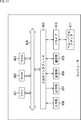
- FIG. 1 shows a configuration example of a distance estimation apparatus as an information processing apparatus according to the present embodiment.
- the distance estimation device 11 is mounted on a vehicle such as an automobile and is configured as a part of a so-called electronic control unit (ECU).
- the distance estimation device 11 estimates a distance from an object such as a preceding vehicle that travels in front of the host vehicle based on signals from various sensors.
- the stereo camera 12, the millimeter wave radar 13, and the polarization camera 14 are mounted on the vehicle as three types of sensors having different detection characteristics.
- the stereo camera 12 is configured by a pair of left and right cameras having a predetermined baseline length on which a solid-state imaging device (CMOS (Complementary Metal Oxide Semiconductor) image sensor or CCD (Charge Coupled Device) image sensor) is mounted.
- CMOS Complementary Metal Oxide Semiconductor
- CCD Charge Coupled Device
- the stereo camera 12 captures the scenery outside the vehicle from different viewpoints.
- the stereo camera 12 is attached, for example, above a room mirror in a vehicle interior, and supplies a right image and a left image obtained by capturing a scene outside the vehicle to the distance estimation device 11.
- Millimeter wave radar 13 detects an object ahead using millimeter waves.
- the millimeter wave radar 13 is attached to, for example, the approximate center of the vehicle front end in the vehicle width direction.
- the millimeter wave radar 13 emits a millimeter wave forward from its own vehicle and receives the millimeter wave reflected at the rear end of the object.
- the millimeter wave radar 13 calculates the distance from the front end of the vehicle to the rear end of the object by measuring the time from emission to reception.
- the millimeter wave radar 13 supplies a signal representing the calculated distance to the distance estimation device 11 as a millimeter wave radar image.
- the polarization camera 14 supplies each image that has passed through polarization filters in three or more directions to the distance estimation device 11.
- the polarization camera 14 has a polarizer array in which a plurality of units (polarizer units) obtained by unitizing three or more polarizers having different transmission axes are combined.
- the polarizer array transmits the non-polarized component of the input light in each polarizer out of the input light that is incident, and transmits the polarized component of the input light having a different polarization direction depending on each polarizer.
- the polarization camera 14 simultaneously captures polarized images composed of different polarization directions and supplies them to the distance estimation device 11.
- the imaging range of each image obtained by the stereo camera 12 and the polarization camera 14 is basically the same, and the imaging range of the image obtained by the millimeter wave radar is the same as that of each image obtained by the stereo camera 12 and the polarization camera 14.
- the range is narrowed down in the vertical direction from the imaging range.
- the distance estimation apparatus 11 includes a stereo camera evaluation unit 51, a millimeter wave radar evaluation unit 52, a polarization angle estimation unit 53, a road surface region estimation unit 54, a non-polarization region extraction unit 55, a low reliability region estimation unit 56, and an obstacle candidate extraction.
- the stereo camera evaluation unit 51 generates a stereo camera distance image and a stereo camera reliability image based on the right image and the left image supplied from the stereo camera 12.
- the stereo camera evaluation unit 51 supplies the stereo camera distance image to the road surface corresponding distance extraction unit 58 and supplies the stereo camera reliability image to the image-map conversion unit 59. Details of the stereo camera distance image and the stereo camera reliability image will be described later.
- the millimeter wave radar evaluation unit 52 generates a millimeter wave radar data map based on the millimeter wave radar image supplied from the millimeter wave radar 13.
- the millimeter wave radar evaluation unit 52 supplies the millimeter wave radar data map to the weight calculation unit 60 and the distance synthesis unit 61. Details of the millimeter wave radar data map will be described later.
- the polarization angle estimation unit 53 generates a polarization angle map indicating the polarization angle of the object in the polarization image based on the polarization image supplied from the polarization camera 14.
- the polarization angle estimation unit 53 supplies the polarization angle map to the road surface region estimation unit 54.
- the road surface area estimation unit 54 estimates a road surface area (road surface area) in the polarization image based on the polarization angle map supplied from the polarization angle estimation unit 53.
- the road surface area estimation unit 54 supplies a road surface area map indicating the road surface area in the polarization image to the low reliability area estimation unit 56, the obstacle candidate extraction unit 57, and the road surface corresponding distance extraction unit 58.
- the non-polarization region extraction unit 55 extracts, as a non-polarization region, a pixel region having a small variation in polarization component intensity in the polarization image based on the polarization image supplied from the polarization camera 14.
- the non-polarization region extraction unit 55 supplies a non-polarization region map indicating the non-polarization region to the low reliability region estimation unit 56.
- the low-reliability area estimation unit 56 uses the reliability in the millimeter wave radar data map based on the road surface area map supplied from the road surface area estimation unit 54 and the non-polarization area map supplied from the non-polarization area extraction unit 55. Estimate the low reliability region with low.
- the low reliability region estimation unit 56 supplies a millimeter wave radar low reliability region map indicating the low reliability region to the weight calculation unit 60.
- the obstacle candidate extraction unit 57 extracts an area that is a candidate for an obstacle in the road surface area based on the road surface area map supplied from the road surface area estimation unit 54.
- the obstacle candidate extraction unit 57 supplies the road surface corresponding distance extraction unit 58 with an in-road surface obstacle candidate region map showing regions that are candidates for the obstacle.
- the road surface corresponding distance extraction unit 58 receives the road surface area map supplied from the road surface area estimation unit 54 and the road surface obstacle candidate area map supplied from the obstacle candidate extraction unit 57 from the stereo camera evaluation unit 51. In the supplied stereo camera distance image, the distance information of the area excluding the area regarded as the road surface is extracted. The road surface corresponding distance extracting unit 58 supplies the stereo camera distance image from which the distance information of the region excluding the region regarded as the road surface is extracted to the image-map converting unit 59 as the road surface corresponding stereo camera distance image.
- the image-map conversion unit 59 is based on the stereo camera reliability image supplied from the stereo camera evaluation unit 51 and the road surface corresponding stereo camera distance image supplied from the road surface corresponding distance extraction unit 58. Is generated.
- the image-map conversion unit 59 supplies the stereo camera reliability map to the weight calculation unit 60 and the distance synthesis unit 61.
- the weight calculation unit 60 includes a millimeter wave radar data map supplied from the millimeter wave radar evaluation unit 52, a millimeter wave radar low reliability region map supplied from the low reliability region estimation unit 56, and an image-map conversion unit 59.
- the weight for the millimeter wave radar data map is calculated on the basis of the stereo camera reliability map supplied from.
- the weight calculation unit 60 supplies a millimeter wave radar weight map indicating weights for the millimeter wave radar data map to the distance synthesis unit 61.
- the distance synthesis unit 61 includes a millimeter wave radar data map supplied from the millimeter wave radar evaluation unit 52, a stereo camera reliability map supplied from the image-map conversion unit 59, and a millimeter wave supplied from the weight calculation unit 60. Based on the radar weight map, the existence likelihood of the object for each distance within the imaging range is calculated. The distance synthesis unit 61 outputs an existence likelihood map indicating the existence likelihood of the object for each distance within the imaging range.
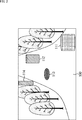
- a non-metal obstacle 111, a metal obstacle 112, and a metal manhole 113 are present on an uphill road surface 100.
- a metal obstacle 114 and a tree exist outside the road surface 100.
- the millimeter wave of the millimeter wave radar 13 is reflected on the manhole 113, and the manhole 113 may be erroneously recognized as an obstacle.
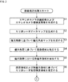
- 3 and 4 are flowcharts for explaining the distance estimation process.
- step S1 the stereo camera evaluation unit 51 generates a stereo camera distance image and a stereo camera reliability image based on the right image and the left image supplied from the stereo camera 12.
- FIG. 5 shows an example of a stereo camera distance image.
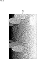
- FIG. 6 shows an example of a stereo camera reliability image.
- the stereo camera reliability image is an image indicating the reliability of distance measurement by the stereo camera 12, and the values of the edge portion and the texture portion in the image are increased.
- the value of the stereo camera reliability image is calculated based on, for example, a stereo matching correlation value in the stereo camera 12.
- the black region is a region with higher reliability.
- the distance is estimated based on the parallax between the left and right images. For this reason, the reliability of a flat portion or dark portion of an image is low, and the reliability of a strong edge portion of the image is high.
- the value of the stereo camera reliability image can be calculated from any object that increases the reliability of the distance estimation of the stereo camera, such as the contrast of the target image and the strength of the texture.
- the stereo camera distance image generated in this way is supplied to the road surface corresponding distance extraction unit 58, and the stereo camera reliability image is supplied to the image-map conversion unit 59.
- an ultrasonic sensor or a laser radar may be provided, and images that replace the stereo camera distance image and the stereo camera reliability image may be generated based on these outputs.
- step S2 the millimeter wave radar evaluation unit 52 generates a millimeter wave radar data map based on the millimeter wave radar image supplied from the millimeter wave radar 13.
- the millimeter wave radar data map shows the position of the object and the reflection intensity of the millimeter wave.
- the value of the millimeter wave radar data map is calculated based on the reflection intensity of the millimeter wave radar 13, for example.
- the reflection intensity of a reflected wave from an object such as metal is high, and a signal representing a distance calculated based on the reflected wave is often reliable. Therefore, by using the millimeter wave radar data map, it is possible to detect an object that reflects a lot of millimeter waves, such as metal, on the road surface and other regions.
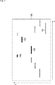
- FIG. 7 shows an example of a millimeter wave radar data map.
- the horizontal axis (x-axis) indicates the horizontal direction in FIG. 2
- the vertical axis (z-axis) indicates the depth direction in FIG.
- the millimeter wave radar data map 140 shown in FIG. 7 indicates that the darker the darker the region, the higher the reliability of the corresponding object.
- the reliability of the region 141 corresponding to the nonmetallic obstacle 111 is high.
- region corresponding to the tree in FIG. 2 is not so high.
- the millimeter wave radar data map generated in this way is supplied to the weight calculation unit 60 and the distance synthesis unit 61.
- step S3 the polarization angle estimation unit 53 generates a polarization angle map based on the polarization image supplied from the polarization camera 14.
- the polarization angle estimation unit 53 separates the polarization component intensity and the non-polarization component intensity from the polarization image using, for example, a mathematical model disclosed in Japanese Patent No. 4974543, and the polarization component intensity indicated by the mathematical model From the phase, the polarization angle of the object in the polarization image is estimated.
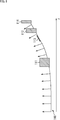
- FIG. 8 shows an example of the polarization angle.
- the polarization angle indicated by the arrow is uniform in the portion corresponding to the front side in the z-axis direction of the road surface 100 in FIG. 2, and corresponds to the back side (uphill) of the road surface 100 in the z-axis direction.
- the polarization angle indicated by the arrow continuously changes in the portion to be changed.
- the polarization angle map indicating the polarization angle estimated in this way is supplied to the road surface area estimation unit 54.
- step S4 the road surface region estimation unit 54 estimates the road surface region in the polarization image based on the polarization angle indicated by the polarization angle map supplied from the polarization angle estimation unit 53.
- the road surface area estimation unit 54 detects a part where the polarization angle indicated by the polarization angle map is uniform over a predetermined range or a part where it continuously changes in the polarization image. And the road surface area estimation part 54 produces
- the road surface area map distinguishes a road surface area from other areas.
- a region where the polarization angle is substantially perpendicular and a region having continuity with such a region are road surface regions.
- FIG. 9 shows an example of a road surface area map.
- the black area is the road surface area.
- a black area in the road surface area map 170 corresponds to a portion excluding the non-metallic obstacle 111, the metal obstacle 112, and the manhole 113 from the road surface 100 in FIG.
- the road surface area map generated in this way is supplied to the low reliability area estimation unit 56, the obstacle candidate extraction unit 57, and the road surface corresponding distance extraction unit 58.
- the road surface area estimation unit 54 estimates the road surface area based on the polarization image. However, for example, the road surface area may be estimated based on the right image and the left image obtained by the stereo camera 12. .
- the non-polarization region extraction unit 55 generates a non-polarization region map indicating the non-polarization region by extracting the non-polarization region in the polarization image supplied from the polarization camera 14. .
- the non-polarized region map indicates a region in which each phase image is (substantially) the same / can be considered in a plurality of polarized images captured by the polarization camera 14. In other words, the non-polarized region map indicates a pixel region in which the variation of the polarization component intensity is small.
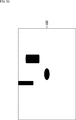
- FIG. 10 shows an example of a non-polarized region map.
- the black regions corresponding to the metal obstacle 112, the manhole 113, and the metal obstacle 114 made of metal in FIG. When the non-polarized light is irradiated onto the metal, the reflected light becomes non-polarized light, so that the non-polarized region can be estimated to be a region corresponding to the metal.
- the non-polarized region map generated in this way is supplied to the low reliability region estimation unit 56.
- a method for estimating the region corresponding to the metal a method other than extracting the non-polarized region in the polarization image may be used.
- step S ⁇ b> 6 the low reliability region estimation unit 56 converts the road surface region map supplied from the road surface region estimation unit 54 and the non-polarization region map supplied from the non-polarization region extraction unit 55. Based on this, a low reliability region in the millimeter wave radar data map is estimated.
- the low reliability region estimation unit 56 extracts a non-polarized region on the road surface region as a low reliability region within the measurement range of the millimeter wave radar 13 from the road surface region map and the non-polarized region map. To do.
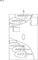
- FIG. 11 is a diagram for explaining the measurement range of the millimeter wave radar 13.
- areas 211, 212, and 213 corresponding to the non-metal obstacle 111, the metal obstacle 112, and the manhole 113 are present on the road surface area 200. Further, an area 214 corresponding to the metal obstacle 114 exists outside the road surface area 200. Further, in the example of FIG. 11, the measurement range 220 of the millimeter wave radar 13 is indicated by a broken-line rectangular frame.
- the non-polarization regions on the road surface region 200 are regions 212 and 213 corresponding to the metal obstacle 112 and the manhole 113, respectively. That is, of the regions 212 and 213, a region included in the measurement range 220 is a low reliability region.
- FIG. 12 shows an example of a millimeter wave radar low reliability region map.
- the millimeter wave radar low reliability area map indicates a low reliability area in the millimeter wave radar data map.
- the non-polarization region indicated by the non-polarization region map is a metal region, and the metal region is a region with low reliability.
- the millimeter wave radar 13 may erroneously recognize the metal on the road surface as an obstacle.
- the black region corresponding to the non-polarized region (that is, the metal region) on the road surface included in the measurement range 220 in FIG. Has been. Therefore, by using the millimeter wave radar low reliability area map, the reliability of the area considered to be metal on the road surface, such as a manhole cover, can be lowered.
- the millimeter wave radar low reliability region map generated in this way is supplied to the weight calculation unit 60.
- step S6 the process proceeds to step S7 of the flowchart of FIG.
- step S ⁇ b> 7 the obstacle candidate extraction unit 57 extracts a region that is a candidate for an obstacle in the road surface region based on the road surface region map supplied from the road surface region estimation unit 54.
- the obstacle candidate extraction unit 57 extracts a region obtained by subtracting the road surface region from all the road surface regions filled in the road surface region as a candidate region for the obstacle in the road surface region map. That is, regions corresponding to the non-metallic obstacle 111, the metallic obstacle 112, and the manhole 113 existing on the road surface are candidate obstacles.
- the road candidate area map in the road surface indicating the obstacle candidate area extracted in this way is supplied to the road surface corresponding distance extraction unit 58.
- the in-road surface obstacle candidate area map shows object area candidates other than the road surface in the road surface area.
- the road surface corresponding distance extracting unit 58 includes the road surface area map supplied from the road surface area estimating unit 54 and the in-road surface obstacle candidate area map supplied from the obstacle candidate extracting unit 57. Based on the above, distance information corresponding to the road surface is excluded from the stereo camera distance image supplied from the stereo camera evaluation unit 51. That is, the road surface corresponding distance extraction unit 58 extracts distance information of a region excluding a region regarded as a road surface in the stereo camera distance image.
- the road surface corresponding distance extraction unit 58 determines that the difference between the distance average of each area that is a candidate for an obstacle on the road surface and the distance average of the road surface area near each area is a predetermined distance. In the case where there are the above, the distance information of each area that is a candidate for the obstacle is left. Further, the road surface corresponding distance extraction unit 58 treats the distance information of the candidate area for the obstacle as infinity when the difference is not greater than the predetermined distance. Further, the road surface corresponding distance extraction unit 58 also handles the distance information of the road surface area as infinity. In this way, a road surface-adaptive stereo camera distance image in which the distance information of the region corresponding to the road surface is excluded from the stereo camera distance image is generated.
- FIG. 13 shows an example of a road surface corresponding stereo camera distance image.
- the area considered as the road surface including the manhole 113 is a black area, that is, an object at infinity. Has been.
- the areas corresponding to the non-metal obstacle 111 and the metal obstacle 112 existing on the road surface remain as objects.
- the road surface-adaptive stereo camera distance image generated in this way is supplied to the image-map converter 59.
- step S ⁇ b> 9 the image-map conversion unit 59 determines the stereo camera reliability image supplied from the stereo camera evaluation unit 51 and the road surface corresponding stereo camera distance supplied from the road surface corresponding distance extraction unit 58.
- a stereo camera reliability map is generated based on the image.
- the image-map conversion unit 59 converts the stereo camera reliability image and the road surface-adaptive stereo camera distance image into an xz map, so that the stereo camera reliability corresponding to the millimeter wave radar data map is obtained. Generate a map.
- FIG. 14 shows an example of a stereo camera reliability map.
- the horizontal axis (x axis) indicates the horizontal direction
- the vertical axis (z axis) indicates the depth direction.
- the reliability of the region 251 corresponding to the non-metallic obstacle 111 and the region corresponding to the tree at a short distance is high. Further, the reliability of the metal obstacle 112 and the areas 252 and 254 corresponding to the metal obstacle 114 at a long distance is not so high. In the example of FIG. 14, it is indicated that the manhole 113 is not recognized as an object.
- the stereo camera reliability map generated in this way is supplied to the weight calculation unit 60 and the distance synthesis unit 61.
- the weight calculation unit 60 includes the millimeter wave radar data map supplied from the millimeter wave radar evaluation unit 52 and the millimeter wave radar low reliability supplied from the low reliability region estimation unit 56.
- a millimeter wave radar weight map is generated based on the region map and the stereo camera reliability map supplied from the image-map converter 59.
- the weight calculation unit 60 uses the millimeter wave radar low reliability area map to change the reliability corresponding to the low reliability area in the millimeter wave radar data map.
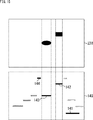
- FIG. 15 is a diagram for explaining the reliability change in the millimeter wave radar data map.
- FIG. 15 shows a millimeter wave radar low reliability region map 230 in the upper part of FIG. 15, and a millimeter wave radar data map 140 in the lower part of FIG.
- the reliability of the regions 142 and 143 having the same horizontal position as the low reliability region in the millimeter wave radar low reliability region map 230 is lowered.
- FIG. 16 shows an example of the millimeter wave radar data map after the reliability change.
- the colors indicating the regions 142 and 143 are displayed lighter than the millimeter wave radar data map 140 shown in FIG. 7, and the reliability is lowered. That is, in the example of FIG. 16, in the millimeter wave radar data map 140, the reliability of the metal obstacle 112 and the manhole 113 existing on the road surface is changed to be low.
- the weight calculating unit 60 uses the value of the millimeter-wave radar data map reliability is changed and the stereo camera reliability map, and calculates a weight w r represented by the following formula (1).
- B mr is the reliability of the millimeter-wave radar 13 at the position r
- B sr indicates the reliability of the stereo camera 12 at the position r.
- Millimeter wave radar weighting map showing the weights w r calculated in this manner is supplied to the distance synthesis unit 61.
- step S11 the distance synthesis unit 61, the millimeter wave radar data map supplied from the millimeter wave radar evaluation unit 52, the stereo camera reliability map supplied from the image-map conversion unit 59, and Based on the millimeter wave radar weight map supplied from the weight calculation unit 60, the existence likelihood of the object for each distance within the imaging range is calculated.
- the existence likelihood L r indicates that the greater the value, the higher the reliability of the existence of the object, that is, the higher the possibility that the object exists.
- the distance synthesis unit 61 outputs an existence likelihood map indicating the existence likelihood L r calculated in this way, and the process ends.
- the existence likelihood map indicates the reliability of the existence of the object at each position, direction, and distance. The larger the value, the higher the reliability of the existence of the object at the position, direction, and distance.
- object detection an object at a certain distance can be detected by performing threshold determination on the value of the existence likelihood map. Note that the threshold value used for the threshold determination may be calculated in advance through experiments or learning.
- the reliability of the millimeter wave radar is assumed to be low.
- Distance estimation is performed. Thereby, it can suppress that the metal on a road surface is misrecognized as an obstruction, and it becomes possible to perform distance estimation correctly by extension.
- the distance to the detected object is a system that outputs a warning of collision to the driver of the own vehicle (a vehicle equipped with the distance estimation device 11), or the own vehicle so as to track other vehicles traveling ahead. It can be used for a system that controls
- the series of processes described above can be executed by hardware or software.
- a program constituting the software is installed in the computer.
- the computer includes, for example, a general-purpose personal computer capable of executing various functions by installing a computer incorporated in dedicated hardware and various programs.
- FIG. 17 is a block diagram showing an example of the hardware configuration of a computer that executes the above-described series of processing by a program.
- a CPU 901 In the computer, a CPU 901, a ROM (Read Only Memory) 902, and a RAM (Random Access Memory) 903 are connected to each other by a bus 904.
- a bus 904. In the computer, a CPU 901, a ROM (Read Only Memory) 902, and a RAM (Random Access Memory) 903 are connected to each other by a bus 904.
- An input / output interface 905 is further connected to the bus 904.
- An input unit 906, an output unit 907, a storage unit 908, a communication unit 909, and a drive 910 are connected to the input / output interface 905.
- the input unit 906 includes a keyboard, a mouse, a microphone, and the like.
- the output unit 907 includes a display, a speaker, and the like.
- the storage unit 908 includes a hard disk, a nonvolatile memory, and the like.
- the communication unit 909 includes a network interface or the like.
- the drive 910 drives a removable medium 911 such as a magnetic disk, an optical disk, a magneto-optical disk, or a semiconductor memory.
- the CPU 901 loads the program stored in the storage unit 908 to the RAM 903 via the input / output interface 905 and the bus 904 and executes the program, for example. Is performed.
- the program executed by the computer (CPU 901) can be provided by being recorded on a removable medium 911 as a package medium, for example.
- the program can be provided via a wired or wireless transmission medium such as a local area network, the Internet, or digital satellite broadcasting.
- the program can be installed in the storage unit 908 via the input / output interface 905 by attaching the removable medium 911 to the drive 910.
- the program can be received by the communication unit 909 via a wired or wireless transmission medium and installed in the storage unit 908.
- the program can be installed in the ROM 902 or the storage unit 908 in advance.
- the program executed by the computer may be a program that is processed in time series in the order described in this specification, or in parallel or at a necessary timing such as when a call is made. It may be a program for processing.
- the present technology can take a cloud computing configuration in which one function is shared by a plurality of devices via a network and is jointly processed.
- each step described in the above flowchart can be executed by one device or can be shared by a plurality of devices.
- the plurality of processes included in the one step can be executed by being shared by a plurality of apparatuses in addition to being executed by one apparatus.
- this technique can take the following structures.
- a road surface area estimation unit that estimates a road surface area in a first image in which a predetermined imaging range is captured;
- a non-polarization region extraction unit that extracts a non-polarization region in the second image in which the imaging range is captured; Based on the information indicating the road surface region and the non-polarized region, the first reliability of the object obtained by the first sensor is low in the measurement range of the first sensor in the imaging range.
- a low reliability region estimation unit for estimating a region; Based on the first reliability, the second reliability of the object obtained by the second sensor in the imaging range, and information indicating the low reliability region, a weight for the first reliability is obtained.
- Information processing device (2) The information processing apparatus according to (1), wherein the weight calculation unit calculates the weight by lowering the first reliability corresponding to the low reliability region.
- a distance information extraction unit that extracts distance information of an area excluding an area regarded as a road surface;
- the information processing apparatus according to (2) further comprising: a reliability generation unit that generates information indicating the second reliability by using distance information of an area excluding an area regarded as the road surface.
- the information processing apparatus includes a reflection intensity of the millimeter wave radar.
- the second reliability includes a correlation value of stereo matching in the stereo camera.
- a weight for the first reliability is obtained.
- An information processing method including a step of calculating a likelihood of existence of the object for each distance within the imaging range based on information indicating the first reliability, the second reliability, and the weight. (11) On the computer, Estimating a road surface area in the first image in which a predetermined imaging range is captured; Extracting a non-polarized region in the second image in which the imaging range is imaged; Based on the information indicating the road surface region and the non-polarized region, the first reliability of the object obtained by the first sensor is low in the measurement range of the first sensor in the imaging range.
- a weight for the first reliability is obtained. Calculate In order to execute processing including a step of calculating the existence likelihood of the object for each distance within the imaging range based on the information indicating the first reliability, the second reliability, and the weight Program.
- 11 distance estimation device 12 stereo camera, 13 millimeter wave radar, 14 polarization camera, 51 stereo camera evaluation section, 52 millimeter wave radar evaluation section, 53 polarization angle estimation section, 54 road surface area estimation section, 55 non-polarization area extraction section, 56 Low reliability region estimation unit, 57 obstacle candidate extraction unit, 58 road surface distance extraction unit, 59 image-map conversion unit, 60 weight calculation unit, 61 distance synthesis unit
Landscapes
- Engineering & Computer Science (AREA)
- Physics & Mathematics (AREA)
- Remote Sensing (AREA)
- Radar, Positioning & Navigation (AREA)
- General Physics & Mathematics (AREA)
- Theoretical Computer Science (AREA)
- Computer Networks & Wireless Communication (AREA)
- Electromagnetism (AREA)
- Multimedia (AREA)
- Computer Vision & Pattern Recognition (AREA)
- Radar Systems Or Details Thereof (AREA)
- Measurement Of Optical Distance (AREA)
- Image Analysis (AREA)
- Image Processing (AREA)
- Traffic Control Systems (AREA)
Abstract
Description
図1は、本実施の形態に係る情報処理装置としての距離推定装置の構成例を示している。
次に、距離推定装置11により実行される距離推定処理について説明する。なお、以下においては、図2に示される風景が、ステレオカメラ12、ミリ波レーダ13、および偏光カメラ14により撮像されるものとする。

(1)
所定の撮像範囲が撮像された第1の画像における路面領域を推定する路面領域推定部と、
前記撮像範囲が撮像された第2の画像における無偏光領域を抽出する無偏光領域抽出部と、
前記路面領域および前記無偏光領域を示す情報に基づいて、前記撮像範囲における第1のセンサの測定範囲内で、前記第1のセンサにより得られる対象物の第1の信頼度が低い低信頼度領域を推定する低信頼度領域推定部と、
前記第1の信頼度、前記撮像範囲において第2のセンサにより得られる前記対象物の第2の信頼度、および前記低信頼度領域を示す情報に基づいて、前記第1の信頼度に対する重みを算出する重み算出部と、
前記第1の信頼度、第2の信頼度、および前記重みを示す情報に基づいて、前記撮像範囲内での距離毎の前記対象物の存在尤度を算出する存在尤度算出部と
を備える情報処理装置。
(2)
前記重み算出部は、前記低信頼度領域に対応する前記第1の信頼度を下げることで、前記重みを算出する
(1)に記載の情報処理装置。
(3)
前記第2のセンサにより得られる前記対象物において、路面とみなされる領域を除いた領域の距離情報を抽出する距離情報抽出部と、
前記路面とみなされる領域を除いた領域の距離情報を用いて、前記第2の信頼度を示す情報を生成する信頼度生成部とをさらに備える
(2)に記載の情報処理装置。
(4)
前記路面領域を示す情報に基づいて、前記路面領域における障害物の候補を抽出する障害物候補抽出部をさらに備え、
前記距離情報抽出部は、前記障害物の候補となる領域の距離情報に基づいて、前記路面とみなされる領域を除いた領域の距離情報を抽出する
(3)に記載の情報処理装置。
(5)
前記第2の画像は、偏光カメラにより得られる3方向以上の偏光画像である
(1)乃至(4)のいずれかに記載の情報処理装置。
(6)
前記第1の画像は、前記第2の画像と同一の画像である
(5)に記載の情報処理装置。
(7)
前記第1のセンサは、ミリ波レーダであり、
前記第2のセンサは、ステレオカメラである
(1)に記載の情報処理装置。
(8)
前記第1の信頼度は、前記ミリ波レーダの反射強度を含む
(7)に記載の情報処理装置。
(9)
前記第2の信頼度は、前記ステレオカメラにおけるステレオマッチングの相関値を含む
(7)または(8)に記載の情報処理装置。
(10)
所定の撮像範囲が撮像された第1の画像における路面領域を推定し、
前記撮像範囲が撮像された第2の画像における無偏光領域を抽出し、
前記路面領域および前記無偏光領域を示す情報に基づいて、前記撮像範囲における第1のセンサの測定範囲内で、前記第1のセンサにより得られる対象物の第1の信頼度が低い低信頼度領域を推定し、
前記第1の信頼度、前記撮像範囲において第2のセンサにより得られる前記対象物の第2の信頼度、および前記低信頼度領域を示す情報に基づいて、前記第1の信頼度に対する重みを算出し、
前記第1の信頼度、第2の信頼度、および前記重みを示す情報に基づいて、前記撮像範囲内での距離毎の前記対象物の存在尤度を算出する
ステップを含む情報処理方法。
(11)
コンピュータに、
所定の撮像範囲が撮像された第1の画像における路面領域を推定し、
前記撮像範囲が撮像された第2の画像における無偏光領域を抽出し、
前記路面領域および前記無偏光領域を示す情報に基づいて、前記撮像範囲における第1のセンサの測定範囲内で、前記第1のセンサにより得られる対象物の第1の信頼度が低い低信頼度領域を推定し、
前記第1の信頼度、前記撮像範囲において第2のセンサにより得られる前記対象物の第2の信頼度、および前記低信頼度領域を示す情報に基づいて、前記第1の信頼度に対する重みを算出し、
前記第1の信頼度、第2の信頼度、および前記重みを示す情報に基づいて、前記撮像範囲内での距離毎の前記対象物の存在尤度を算出する
ステップを含む処理を実行させるためのプログラム。
Claims (11)
- 所定の撮像範囲が撮像された第1の画像における路面領域を推定する路面領域推定部と、
前記撮像範囲が撮像された第2の画像における無偏光領域を抽出する無偏光領域抽出部と、
前記路面領域および前記無偏光領域を示す情報に基づいて、前記撮像範囲における第1のセンサの測定範囲内で、前記第1のセンサにより得られる対象物の第1の信頼度が低い低信頼度領域を推定する低信頼度領域推定部と、
前記第1の信頼度、前記撮像範囲において第2のセンサにより得られる前記対象物の第2の信頼度、および前記低信頼度領域を示す情報に基づいて、前記第1の信頼度に対する重みを算出する重み算出部と、
前記第1の信頼度、第2の信頼度、および前記重みを示す情報に基づいて、前記撮像範囲内での距離毎の前記対象物の存在尤度を算出する存在尤度算出部と
を備える情報処理装置。 - 前記重み算出部は、前記低信頼度領域に対応する前記第1の信頼度を下げることで、前記重みを算出する
請求項1に記載の情報処理装置。 - 前記第2のセンサにより得られる前記対象物において、路面とみなされる領域を除いた領域の距離情報を抽出する距離情報抽出部と、
前記路面とみなされる領域を除いた領域の距離情報を用いて、前記第2の信頼度を示す情報を生成する信頼度生成部とをさらに備える
請求項2に記載の情報処理装置。 - 前記路面領域を示す情報に基づいて、前記路面領域における障害物の候補を抽出する障害物候補抽出部をさらに備え、
前記距離情報抽出部は、前記障害物の候補となる領域の距離情報に基づいて、前記路面とみなされる領域を除いた領域の距離情報を抽出する
請求項3に記載の情報処理装置。 - 前記第2の画像は、偏光カメラにより得られる3方向以上の偏光画像である
請求項4に記載の情報処理装置。 - 前記第1の画像は、前記第2の画像と同一の画像である
請求項5に記載の情報処理装置。 - 前記第1のセンサは、ミリ波レーダであり、
前記第2のセンサは、ステレオカメラである
請求項1に記載の情報処理装置。 - 前記第1の信頼度は、前記ミリ波レーダの反射強度を含む
請求項7に記載の情報処理装置。 - 前記第2の信頼度は、前記ステレオカメラにおけるステレオマッチングの相関値を含む
請求項7に記載の情報処理装置。 - 所定の撮像範囲が撮像された第1の画像における路面領域を推定し、
前記撮像範囲が撮像された第2の画像における無偏光領域を抽出し、
前記路面領域および前記無偏光領域を示す情報に基づいて、前記撮像範囲における第1のセンサの測定範囲内で、前記第1のセンサにより得られる対象物の第1の信頼度が低い低信頼度領域を推定し、
前記第1の信頼度、前記撮像範囲において第2のセンサにより得られる前記対象物の第2の信頼度、および前記低信頼度領域を示す情報に基づいて、前記第1の信頼度に対する重みを算出し、
前記第1の信頼度、第2の信頼度、および前記重みを示す情報に基づいて、前記撮像範囲内での距離毎の前記対象物の存在尤度を算出する
ステップを含む情報処理方法。 - コンピュータに、
所定の撮像範囲が撮像された第1の画像における路面領域を推定し、
前記撮像範囲が撮像された第2の画像における無偏光領域を抽出し、
前記路面領域および前記無偏光領域を示す情報に基づいて、前記撮像範囲における第1のセンサの測定範囲内で、前記第1のセンサにより得られる対象物の第1の信頼度が低い低信頼度領域を推定し、
前記第1の信頼度、前記撮像範囲において第2のセンサにより得られる前記対象物の第2の信頼度、および前記低信頼度領域を示す情報に基づいて、前記第1の信頼度に対する重みを算出し、
前記第1の信頼度、第2の信頼度、および前記重みを示す情報に基づいて、前記撮像範囲内での距離毎の前記対象物の存在尤度を算出する
ステップを含む処理を実行させるためのプログラム。
Priority Applications (4)
| Application Number | Priority Date | Filing Date | Title |
|---|---|---|---|
| JP2017543146A JP6784943B2 (ja) | 2015-09-30 | 2016-09-16 | 情報処理装置、情報処理方法、およびプログラム |
| CN201680055467.3A CN108028023B (zh) | 2015-09-30 | 2016-09-16 | 信息处理装置、信息处理方法和计算机可读存储介质 |
| EP16851232.5A EP3358551B1 (en) | 2015-09-30 | 2016-09-16 | Information processing device, information processing method, and program |
| US15/762,309 US10591594B2 (en) | 2015-09-30 | 2016-09-16 | Information processing apparatus, information processing method, and program |
Applications Claiming Priority (2)
| Application Number | Priority Date | Filing Date | Title |
|---|---|---|---|
| JP2015194137 | 2015-09-30 | ||
| JP2015-194137 | 2015-09-30 |
Publications (1)
| Publication Number | Publication Date |
|---|---|
| WO2017057058A1 true WO2017057058A1 (ja) | 2017-04-06 |
Family
ID=58423744
Family Applications (1)
| Application Number | Title | Priority Date | Filing Date |
|---|---|---|---|
| PCT/JP2016/077431 WO2017057058A1 (ja) | 2015-09-30 | 2016-09-16 | 情報処理装置、情報処理方法、およびプログラム |
Country Status (5)
| Country | Link |
|---|---|
| US (1) | US10591594B2 (ja) |
| EP (1) | EP3358551B1 (ja) |
| JP (1) | JP6784943B2 (ja) |
| CN (1) | CN108028023B (ja) |
| WO (1) | WO2017057058A1 (ja) |
Cited By (13)
| Publication number | Priority date | Publication date | Assignee | Title |
|---|---|---|---|---|
| JP2019020167A (ja) * | 2017-07-12 | 2019-02-07 | 株式会社デンソーテン | レーダ装置及び信号処理方法 |
| JP2019032700A (ja) * | 2017-08-08 | 2019-02-28 | 株式会社東芝 | 情報処理装置、情報処理方法、プログラムおよび移動体 |
| CN110232836A (zh) * | 2018-03-06 | 2019-09-13 | 丰田自动车株式会社 | 物体识别装置以及车辆行驶控制系统 |
| JP2019178971A (ja) * | 2018-03-30 | 2019-10-17 | パナソニックIpマネジメント株式会社 | 環境地図生成装置、環境地図生成方法、及び環境地図生成プログラム |
| JP2020085872A (ja) * | 2018-11-30 | 2020-06-04 | 古河電気工業株式会社 | センサシステム、センサ装置、および、異常検出方法 |
| EP3663882A4 (en) * | 2017-08-04 | 2020-08-12 | Sony Corporation | INFORMATION PROCESSING DEVICE, INFORMATION PROCESSING PROCESS, PROGRAM AND MOBILE UNIT |
| JP2021086298A (ja) * | 2019-11-26 | 2021-06-03 | 日立Astemo株式会社 | 移動体の制御装置及び方法 |
| WO2021131953A1 (ja) * | 2019-12-27 | 2021-07-01 | ソニーセミコンダクタソリューションズ株式会社 | 情報処理装置、情報処理システム、情報処理プログラムおよび情報処理方法 |
| JP2022543955A (ja) * | 2020-06-30 | 2022-10-17 | ベイジン・センスタイム・テクノロジー・デベロップメント・カンパニー・リミテッド | 目標車両の制御方法、装置、電子機器及び記憶媒体 |
| JP2022550216A (ja) * | 2019-11-30 | 2022-11-30 | ボストン ポーラリメトリックス,インコーポレイティド | 偏光キューを用いた透明な物体のセグメンテーションのためのシステム及び方法 |
| US11782145B1 (en) | 2022-06-14 | 2023-10-10 | Nodar Inc. | 3D vision system with automatically calibrated stereo vision sensors and LiDAR sensor |
| US11983899B2 (en) | 2020-01-22 | 2024-05-14 | Nodar Inc. | Stereo vision camera system that tracks and filters calibration parameters |
| US12043283B2 (en) | 2021-10-08 | 2024-07-23 | Nodar Inc. | Detection of near-range and far-range small objects for autonomous vehicles |
Families Citing this family (14)
| Publication number | Priority date | Publication date | Assignee | Title |
|---|---|---|---|---|
| JP6881307B2 (ja) | 2015-09-30 | 2021-06-02 | ソニーグループ株式会社 | 情報処理装置、情報処理方法、及び、プログラム |
| EP3318890B1 (en) * | 2016-11-02 | 2019-05-01 | Aptiv Technologies Limited | Method to provide a vehicle environment contour polyline from detection data |
| US10318827B2 (en) * | 2016-12-19 | 2019-06-11 | Waymo Llc | Object detection neural networks |
| WO2019031851A1 (ko) * | 2017-08-08 | 2019-02-14 | 엘지전자 주식회사 | 지도 제공 장치 |
| JP7511471B2 (ja) * | 2018-07-02 | 2024-07-05 | ソニーセミコンダクタソリューションズ株式会社 | 情報処理装置及び情報処理方法、コンピュータプログラム、並びに移動体装置 |
| DE102018216983B3 (de) | 2018-10-04 | 2019-11-28 | Audi Ag | Verfahren zum Unterdrücken von Abbildungen von Reflexionen in zumindest einem Kamerabild einer Kamera einer Umfeldsensorvorrichtung eines Kraftfahrzeugs sowie entsprechende Umfeldsensorvorrichtung |
| US11899099B2 (en) | 2018-11-30 | 2024-02-13 | Qualcomm Incorporated | Early fusion of camera and radar frames |
| US11987271B2 (en) | 2018-12-07 | 2024-05-21 | Sony Semiconductor Solutions Corporation | Information processing apparatus, information processing method, mobile-object control apparatus, and mobile object |
| US20220172490A1 (en) * | 2019-03-26 | 2022-06-02 | Sony Semiconductor Solutions Corporation | Image processing apparatus, vehicle control apparatus, method, and program |
| US11427193B2 (en) | 2020-01-22 | 2022-08-30 | Nodar Inc. | Methods and systems for providing depth maps with confidence estimates |
| KR20210152741A (ko) * | 2020-06-09 | 2021-12-16 | 삼성전자주식회사 | 첨단 운전자 지원 장치 및 이의 객체를 검출하는 방법 |
| JP7525936B2 (ja) * | 2021-01-06 | 2024-07-31 | ノダー インコーポレイテッド | 確信度推定値を有する深度マップを提供するための方法およびシステム |
| US11398153B1 (en) * | 2021-03-02 | 2022-07-26 | Here Global B.V. | System and method for determining a driving direction |
| CN113851000A (zh) * | 2021-09-10 | 2021-12-28 | 泰州蝶金软件有限公司 | 基于云计算的命令解析系统 |
Citations (3)
| Publication number | Priority date | Publication date | Assignee | Title |
|---|---|---|---|---|
| JP2011150689A (ja) * | 2009-12-25 | 2011-08-04 | Ricoh Co Ltd | 撮像装置、車載用撮像システム、路面外観認識方法及び物体識別装置 |
| JP2012033149A (ja) * | 2010-07-01 | 2012-02-16 | Ricoh Co Ltd | 物体識別装置 |
| JP2015143979A (ja) * | 2013-12-27 | 2015-08-06 | 株式会社リコー | 画像処理装置、画像処理方法、プログラム、画像処理システム |
Family Cites Families (9)
| Publication number | Priority date | Publication date | Assignee | Title |
|---|---|---|---|---|
| JP2900737B2 (ja) | 1993-02-01 | 1999-06-02 | トヨタ自動車株式会社 | 車間距離検出装置 |
| JP3669205B2 (ja) * | 1999-05-17 | 2005-07-06 | 日産自動車株式会社 | 障害物認識装置 |
| JP2007310741A (ja) | 2006-05-19 | 2007-11-29 | Fuji Heavy Ind Ltd | 立体物認識装置 |
| JP2008116357A (ja) | 2006-11-06 | 2008-05-22 | Toyota Motor Corp | 物体検出装置 |
| BRPI0823237A2 (pt) * | 2008-11-07 | 2015-06-16 | Volvo Lastvagnar Ab | Método e sistema para combinação de dados de sensor |
| JP5556508B2 (ja) * | 2010-08-30 | 2014-07-23 | 株式会社デンソー | 物体検出装置 |
| CN104573646B (zh) * | 2014-12-29 | 2017-12-12 | 长安大学 | 基于激光雷达和双目相机的车前行人检测方法及系统 |
| JP6046190B2 (ja) * | 2015-03-31 | 2016-12-14 | 本田技研工業株式会社 | 運転支援装置 |
| JP6365385B2 (ja) * | 2015-04-17 | 2018-08-01 | トヨタ自動車株式会社 | 立体物検出装置及び立体物検出方法 |
-
2016
- 2016-09-16 JP JP2017543146A patent/JP6784943B2/ja not_active Expired - Fee Related
- 2016-09-16 WO PCT/JP2016/077431 patent/WO2017057058A1/ja active Application Filing
- 2016-09-16 CN CN201680055467.3A patent/CN108028023B/zh not_active Expired - Fee Related
- 2016-09-16 EP EP16851232.5A patent/EP3358551B1/en active Active
- 2016-09-16 US US15/762,309 patent/US10591594B2/en not_active Expired - Fee Related
Patent Citations (3)
| Publication number | Priority date | Publication date | Assignee | Title |
|---|---|---|---|---|
| JP2011150689A (ja) * | 2009-12-25 | 2011-08-04 | Ricoh Co Ltd | 撮像装置、車載用撮像システム、路面外観認識方法及び物体識別装置 |
| JP2012033149A (ja) * | 2010-07-01 | 2012-02-16 | Ricoh Co Ltd | 物体識別装置 |
| JP2015143979A (ja) * | 2013-12-27 | 2015-08-06 | 株式会社リコー | 画像処理装置、画像処理方法、プログラム、画像処理システム |
Non-Patent Citations (1)
| Title |
|---|
| See also references of EP3358551A4 * |
Cited By (22)
| Publication number | Priority date | Publication date | Assignee | Title |
|---|---|---|---|---|
| JP2019020167A (ja) * | 2017-07-12 | 2019-02-07 | 株式会社デンソーテン | レーダ装置及び信号処理方法 |
| JP7127969B2 (ja) | 2017-07-12 | 2022-08-30 | 株式会社デンソーテン | レーダ装置及び信号処理方法 |
| US11373418B2 (en) | 2017-08-04 | 2022-06-28 | Sony Corporation | Information processing apparatus, information processing method, program, and mobile object |
| EP3663882A4 (en) * | 2017-08-04 | 2020-08-12 | Sony Corporation | INFORMATION PROCESSING DEVICE, INFORMATION PROCESSING PROCESS, PROGRAM AND MOBILE UNIT |
| JP2019032700A (ja) * | 2017-08-08 | 2019-02-28 | 株式会社東芝 | 情報処理装置、情報処理方法、プログラムおよび移動体 |
| US10885353B2 (en) | 2017-08-08 | 2021-01-05 | Kabushiki Kaisha Toshiba | Information processing apparatus, moving object, information processing method, and computer program product |
| CN110232836B (zh) * | 2018-03-06 | 2021-11-05 | 丰田自动车株式会社 | 物体识别装置以及车辆行驶控制系统 |
| CN110232836A (zh) * | 2018-03-06 | 2019-09-13 | 丰田自动车株式会社 | 物体识别装置以及车辆行驶控制系统 |
| JP2019178971A (ja) * | 2018-03-30 | 2019-10-17 | パナソニックIpマネジメント株式会社 | 環境地図生成装置、環境地図生成方法、及び環境地図生成プログラム |
| JP2020085872A (ja) * | 2018-11-30 | 2020-06-04 | 古河電気工業株式会社 | センサシステム、センサ装置、および、異常検出方法 |
| JP7203583B2 (ja) | 2018-11-30 | 2023-01-13 | 古河電気工業株式会社 | センサシステム、センサ装置、および、異常検出方法 |
| JP2021086298A (ja) * | 2019-11-26 | 2021-06-03 | 日立Astemo株式会社 | 移動体の制御装置及び方法 |
| DE112020005077T5 (de) | 2019-11-26 | 2022-07-28 | Hitachi Astemo, Ltd. | Einrichtung und verfahren zum steuern eines mobilen körpers |
| JP7401273B2 (ja) | 2019-11-26 | 2023-12-19 | 日立Astemo株式会社 | 移動体の制御装置及び方法 |
| JP2022550216A (ja) * | 2019-11-30 | 2022-11-30 | ボストン ポーラリメトリックス,インコーポレイティド | 偏光キューを用いた透明な物体のセグメンテーションのためのシステム及び方法 |
| JP7329143B2 (ja) | 2019-11-30 | 2023-08-17 | ボストン ポーラリメトリックス,インコーポレイティド | 偏光キューを用いた透明な物体のセグメンテーションのためのシステム及び方法 |
| US11842495B2 (en) | 2019-11-30 | 2023-12-12 | Intrinsic Innovation Llc | Systems and methods for transparent object segmentation using polarization cues |
| WO2021131953A1 (ja) * | 2019-12-27 | 2021-07-01 | ソニーセミコンダクタソリューションズ株式会社 | 情報処理装置、情報処理システム、情報処理プログラムおよび情報処理方法 |
| US11983899B2 (en) | 2020-01-22 | 2024-05-14 | Nodar Inc. | Stereo vision camera system that tracks and filters calibration parameters |
| JP2022543955A (ja) * | 2020-06-30 | 2022-10-17 | ベイジン・センスタイム・テクノロジー・デベロップメント・カンパニー・リミテッド | 目標車両の制御方法、装置、電子機器及び記憶媒体 |
| US12043283B2 (en) | 2021-10-08 | 2024-07-23 | Nodar Inc. | Detection of near-range and far-range small objects for autonomous vehicles |
| US11782145B1 (en) | 2022-06-14 | 2023-10-10 | Nodar Inc. | 3D vision system with automatically calibrated stereo vision sensors and LiDAR sensor |
Also Published As
| Publication number | Publication date |
|---|---|
| JPWO2017057058A1 (ja) | 2018-08-30 |
| US10591594B2 (en) | 2020-03-17 |
| EP3358551A1 (en) | 2018-08-08 |
| CN108028023A (zh) | 2018-05-11 |
| EP3358551B1 (en) | 2021-10-27 |
| EP3358551A4 (en) | 2019-03-13 |
| CN108028023B (zh) | 2021-10-26 |
| US20180284260A1 (en) | 2018-10-04 |
| JP6784943B2 (ja) | 2020-11-18 |
Similar Documents
| Publication | Publication Date | Title |
|---|---|---|
| WO2017057058A1 (ja) | 情報処理装置、情報処理方法、およびプログラム | |
| JP5689907B2 (ja) | 車両において通行物体位置検出を向上する方法 | |
| US10861176B2 (en) | Systems and methods for enhanced distance estimation by a mono-camera using radar and motion data | |
| CN110573905B (zh) | 障碍物检知装置 | |
| JP5991332B2 (ja) | 衝突回避制御装置 | |
| WO2018079252A1 (ja) | 物体検知装置 | |
| JP4883246B2 (ja) | 物体検出装置及び物体検出方法 | |
| US10836388B2 (en) | Vehicle control method and apparatus | |
| US10846542B2 (en) | Systems and methods for augmentating upright object detection | |
| US9747524B2 (en) | Disparity value deriving device, equipment control system, movable apparatus, and robot | |
| JP2008116357A (ja) | 物体検出装置 | |
| JP6703471B2 (ja) | 物体検知装置 | |
| JP4052291B2 (ja) | 車両用画像処理装置 | |
| JP2017009572A5 (ja) | ||
| EP2913999A1 (en) | Disparity value deriving device, equipment control system, movable apparatus, robot, disparity value deriving method, and computer-readable storage medium | |
| KR100962329B1 (ko) | 스테레오 카메라 영상으로부터의 지면 추출 방법과 장치 및이와 같은 방법을 구현하는 프로그램이 기록된 기록매체 | |
| JP7135579B2 (ja) | 物体検知装置 | |
| JP2021025945A (ja) | 物標検出装置 | |
| JP2023068009A (ja) | 地図情報作成方法 | |
| JP2006072757A (ja) | 物体検出装置 | |
| JP5783163B2 (ja) | 物標検出装置 | |
| EP3217357B1 (en) | Estimation of movement of a target object | |
| JP7064400B2 (ja) | 物体検知装置 | |
| WO2020036039A1 (ja) | ステレオカメラ装置 | |
| EP2919191B1 (en) | Disparity value deriving device, equipment control system, movable apparatus, robot, and disparity value producing method |
Legal Events
| Date | Code | Title | Description |
|---|---|---|---|
| 121 | Ep: the epo has been informed by wipo that ep was designated in this application |
Ref document number: 16851232 Country of ref document: EP Kind code of ref document: A1 |
|
| ENP | Entry into the national phase |
Ref document number: 2017543146 Country of ref document: JP Kind code of ref document: A |
|
| WWE | Wipo information: entry into national phase |
Ref document number: 15762309 Country of ref document: US |
|
| NENP | Non-entry into the national phase |
Ref country code: DE |
|
| WWE | Wipo information: entry into national phase |
Ref document number: 2016851232 Country of ref document: EP |