WO2017057043A1 - 画像処理装置、画像処理方法、およびプログラム - Google Patents
画像処理装置、画像処理方法、およびプログラム Download PDFInfo
- Publication number
- WO2017057043A1 WO2017057043A1 PCT/JP2016/077399 JP2016077399W WO2017057043A1 WO 2017057043 A1 WO2017057043 A1 WO 2017057043A1 JP 2016077399 W JP2016077399 W JP 2016077399W WO 2017057043 A1 WO2017057043 A1 WO 2017057043A1
- Authority
- WO
- WIPO (PCT)
- Prior art keywords
- unit
- camera
- image
- vehicle
- feature point
- Prior art date
Links
Images


Classifications
-
- G—PHYSICS
- G06—COMPUTING; CALCULATING OR COUNTING
- G06T—IMAGE DATA PROCESSING OR GENERATION, IN GENERAL
- G06T7/00—Image analysis
- G06T7/80—Analysis of captured images to determine intrinsic or extrinsic camera parameters, i.e. camera calibration
-
- G—PHYSICS
- G01—MEASURING; TESTING
- G01C—MEASURING DISTANCES, LEVELS OR BEARINGS; SURVEYING; NAVIGATION; GYROSCOPIC INSTRUMENTS; PHOTOGRAMMETRY OR VIDEOGRAMMETRY
- G01C21/00—Navigation; Navigational instruments not provided for in groups G01C1/00 - G01C19/00
- G01C21/005—Navigation; Navigational instruments not provided for in groups G01C1/00 - G01C19/00 with correlation of navigation data from several sources, e.g. map or contour matching
-
- G—PHYSICS
- G01—MEASURING; TESTING
- G01C—MEASURING DISTANCES, LEVELS OR BEARINGS; SURVEYING; NAVIGATION; GYROSCOPIC INSTRUMENTS; PHOTOGRAMMETRY OR VIDEOGRAMMETRY
- G01C25/00—Manufacturing, calibrating, cleaning, or repairing instruments or devices referred to in the other groups of this subclass
-
- G—PHYSICS
- G01—MEASURING; TESTING
- G01C—MEASURING DISTANCES, LEVELS OR BEARINGS; SURVEYING; NAVIGATION; GYROSCOPIC INSTRUMENTS; PHOTOGRAMMETRY OR VIDEOGRAMMETRY
- G01C3/00—Measuring distances in line of sight; Optical rangefinders
- G01C3/10—Measuring distances in line of sight; Optical rangefinders using a parallactic triangle with variable angles and a base of fixed length in the observation station, e.g. in the instrument
- G01C3/18—Measuring distances in line of sight; Optical rangefinders using a parallactic triangle with variable angles and a base of fixed length in the observation station, e.g. in the instrument with one observation point at each end of the base
-
- G—PHYSICS
- G06—COMPUTING; CALCULATING OR COUNTING
- G06T—IMAGE DATA PROCESSING OR GENERATION, IN GENERAL
- G06T7/00—Image analysis
- G06T7/70—Determining position or orientation of objects or cameras
- G06T7/73—Determining position or orientation of objects or cameras using feature-based methods
- G06T7/74—Determining position or orientation of objects or cameras using feature-based methods involving reference images or patches
-
- G—PHYSICS
- G06—COMPUTING; CALCULATING OR COUNTING
- G06T—IMAGE DATA PROCESSING OR GENERATION, IN GENERAL
- G06T7/00—Image analysis
- G06T7/80—Analysis of captured images to determine intrinsic or extrinsic camera parameters, i.e. camera calibration
- G06T7/85—Stereo camera calibration
-
- H—ELECTRICITY
- H04—ELECTRIC COMMUNICATION TECHNIQUE
- H04N—PICTORIAL COMMUNICATION, e.g. TELEVISION
- H04N13/00—Stereoscopic video systems; Multi-view video systems; Details thereof
- H04N13/20—Image signal generators
- H04N13/204—Image signal generators using stereoscopic image cameras
- H04N13/207—Image signal generators using stereoscopic image cameras using a single 2D image sensor
-
- H—ELECTRICITY
- H04—ELECTRIC COMMUNICATION TECHNIQUE
- H04N—PICTORIAL COMMUNICATION, e.g. TELEVISION
- H04N13/00—Stereoscopic video systems; Multi-view video systems; Details thereof
- H04N13/20—Image signal generators
- H04N13/204—Image signal generators using stereoscopic image cameras
- H04N13/243—Image signal generators using stereoscopic image cameras using three or more 2D image sensors
-
- H—ELECTRICITY
- H04—ELECTRIC COMMUNICATION TECHNIQUE
- H04N—PICTORIAL COMMUNICATION, e.g. TELEVISION
- H04N13/00—Stereoscopic video systems; Multi-view video systems; Details thereof
- H04N13/20—Image signal generators
- H04N13/204—Image signal generators using stereoscopic image cameras
- H04N13/246—Calibration of cameras
-
- H—ELECTRICITY
- H04—ELECTRIC COMMUNICATION TECHNIQUE
- H04N—PICTORIAL COMMUNICATION, e.g. TELEVISION
- H04N17/00—Diagnosis, testing or measuring for television systems or their details
- H04N17/002—Diagnosis, testing or measuring for television systems or their details for television cameras
-
- G—PHYSICS
- G01—MEASURING; TESTING
- G01S—RADIO DIRECTION-FINDING; RADIO NAVIGATION; DETERMINING DISTANCE OR VELOCITY BY USE OF RADIO WAVES; LOCATING OR PRESENCE-DETECTING BY USE OF THE REFLECTION OR RERADIATION OF RADIO WAVES; ANALOGOUS ARRANGEMENTS USING OTHER WAVES
- G01S17/00—Systems using the reflection or reradiation of electromagnetic waves other than radio waves, e.g. lidar systems
- G01S17/88—Lidar systems specially adapted for specific applications
- G01S17/93—Lidar systems specially adapted for specific applications for anti-collision purposes
- G01S17/931—Lidar systems specially adapted for specific applications for anti-collision purposes of land vehicles
-
- G—PHYSICS
- G06—COMPUTING; CALCULATING OR COUNTING
- G06T—IMAGE DATA PROCESSING OR GENERATION, IN GENERAL
- G06T2207/00—Indexing scheme for image analysis or image enhancement
- G06T2207/10—Image acquisition modality
- G06T2207/10004—Still image; Photographic image
- G06T2207/10012—Stereo images
-
- G—PHYSICS
- G06—COMPUTING; CALCULATING OR COUNTING
- G06T—IMAGE DATA PROCESSING OR GENERATION, IN GENERAL
- G06T2207/00—Indexing scheme for image analysis or image enhancement
- G06T2207/30—Subject of image; Context of image processing
- G06T2207/30248—Vehicle exterior or interior
- G06T2207/30252—Vehicle exterior; Vicinity of vehicle
-
- G—PHYSICS
- G06—COMPUTING; CALCULATING OR COUNTING
- G06T—IMAGE DATA PROCESSING OR GENERATION, IN GENERAL
- G06T7/00—Image analysis
- G06T7/50—Depth or shape recovery
- G06T7/55—Depth or shape recovery from multiple images
- G06T7/579—Depth or shape recovery from multiple images from motion
-
- G—PHYSICS
- G06—COMPUTING; CALCULATING OR COUNTING
- G06T—IMAGE DATA PROCESSING OR GENERATION, IN GENERAL
- G06T7/00—Image analysis
- G06T7/50—Depth or shape recovery
- G06T7/55—Depth or shape recovery from multiple images
- G06T7/593—Depth or shape recovery from multiple images from stereo images
-
- H—ELECTRICITY
- H04—ELECTRIC COMMUNICATION TECHNIQUE
- H04N—PICTORIAL COMMUNICATION, e.g. TELEVISION
- H04N23/00—Cameras or camera modules comprising electronic image sensors; Control thereof
- H04N23/90—Arrangement of cameras or camera modules, e.g. multiple cameras in TV studios or sports stadiums
Definitions
- the present disclosure relates to an image processing device, an image processing method, and a program, and in particular, enables calibration of a camera with high accuracy using known objects in images captured by a plurality of imaging units.
- the present invention relates to an image processing apparatus, an image processing method, and a program.
- a method for correcting an image captured by a camera is known as a method for controlling the relationship between the three-dimensional positions and orientations of the cameras to be a predetermined relationship.
- a method for determining parameters used for image correction that is, a method for calibrating a camera, for example, each camera captures a specific pattern and corrects the resulting image to be a desired image. There is a way to ask. In this method, since it is necessary to image a specific pattern, it is difficult to periodically update the parameters.
- the present disclosure has been made in view of such a situation, and enables calibration of a camera with high accuracy by using a known object in an image captured by a plurality of imaging units. It is.
- An image processing apparatus includes an estimation unit that estimates a three-dimensional position of each known object included in each image captured by a plurality of imaging units, and the estimation unit that estimates the three-dimensional position.
- a recognition unit that recognizes a positional relationship between the plurality of imaging units based on a three-dimensional position of each known object with respect to each imaging unit, and a plurality of the imaging units that are based on the positional relationship recognized by the recognition unit.
- a correction unit that corrects the image picked up by the image processing apparatus.
- the image processing method and program according to one aspect of the present disclosure correspond to the image processing apparatus according to one aspect of the present disclosure.
- a three-dimensional position of a known object included in each image captured by a plurality of imaging units with respect to each imaging unit is estimated, and the estimated three-dimensional position of the known object with respect to each imaging unit Based on the above, the positional relationship between the plurality of imaging units is recognized, and the images captured by the plurality of imaging units are corrected based on the recognized positional relationship.
- image processing can be performed.
- FIG. 3 is a flowchart illustrating image processing of the image processing apparatus in FIG. 2. It is a flowchart explaining the detail of the calibration determination process of FIG. It is a flowchart explaining the detail of the camera relation recognition process of FIG. It is a figure which shows the outline
- First embodiment vehicle-mounted camera system (FIGS. 1 to 7) 2.
- Second embodiment vehicle-mounted camera system (FIGS. 8 and 9) 3.
- Third Embodiment In-vehicle camera system (FIG. 10) 4).
- Fourth embodiment vehicle-mounted camera system (FIGS. 11 to 13) 5.
- Fifth embodiment vehicle-mounted camera system (FIG. 14) 6).
- Sixth Embodiment Computer (FIG. 15) 7).
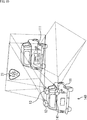
- FIG. 1 is a diagram illustrating an overview of a first embodiment of an in-vehicle camera system to which the present disclosure is applied.
- the vehicle 1 includes an automobile vehicle 11, a camera 12, a camera 13, and the like.
- the front, rear, right side, and left side are referred to as the front, rear, right side, and left side of the vehicle 11, respectively, in the traveling direction of the vehicle 11 during normal operation.
- the camera 12 (first imaging unit) and the camera 13 (second imaging unit) are mounted in front of the roof of the vehicle 11 so that the imaging areas overlap.
- a road sign 21 that is a known object in front of the vehicle 11 is included in the imaging regions of the camera 12 and the camera 13.
- the road sign 21 is a known object. If the known object is an object having a known size and shape, an object on the road other than the road sign, or a license plate, an emblem, etc. The object etc. which the vehicle 11 or another vehicle has may be sufficient.
- An image processing device mounted on the vehicle 11 estimates the three-dimensional position and orientation of the road sign 21 with respect to each of the camera 12 and the camera 13.
- the three-dimensional position with respect to the camera 12 (camera 13) is, for example, a predetermined position (for example, the center) on the imaging surface of the camera 12 (camera 13) as the origin, and the horizontal and vertical directions of the imaging surface, These are positions in the x direction, y direction, and z direction when the directions perpendicular to the imaging surface are the x direction, y direction, and z direction, respectively.
- the direction with respect to the camera 12 (camera 13) is, for example, a rotation angle with the x direction, the y direction, and the z direction as axes.
- the image processing apparatus recognizes the relationship between the three-dimensional position and orientation of the camera 12 and the camera 13 on the basis of the three-dimensional position and orientation of the road sign 21 with respect to the camera 12 and the camera 13, respectively.
- the camera 13 is calibrated.
- the relationship between the three-dimensional positions of the camera 12 and the camera 13 includes, for example, a predetermined position (for example, the center) on one imaging surface of the camera 12 or the camera 13, and the horizontal and vertical directions of the imaging surface,
- the x-, y-, and z-direction positions of a predetermined position on the other imaging surface when the directions perpendicular to the imaging surface are the x-direction, y-direction, and z-direction, respectively.
- the orientation relationship between the camera 12 and the camera 13 is, for example, the rotation angle of the other imaging surface with the x direction, the y direction, and the z direction as axes.
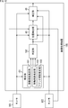
- FIG. 2 is a block diagram illustrating a configuration example of the image processing apparatus mounted on the vehicle 11 of FIG.
- a movement amount estimation unit 41 includes a movement amount estimation unit 41, a determination unit 42, a movement amount estimation unit 43, a determination unit 44, a position detection unit 45, and a correction unit 46.
- the image captured by the camera 12 and the camera 13 is input to the image processing device 40.
- the image captured by the camera 12 is supplied to the movement amount estimation unit 41, the movement amount estimation unit 43, the position detection unit 45, and the correction unit 46.
- the image captured by the camera 13 is the movement amount estimation unit 41, the movement amount.
- the amount is supplied to the quantity estimation unit 43, the position detection unit 45, and the correction unit 46.
- imaging parameters are input to the image processing apparatus 40 from each of the camera 12 and the camera 13 and supplied to the position detection unit 45.
- the imaging parameters are internal parameters such as horizontal and vertical enlargement ratios calculated based on focal length, pixel size, etc., and the position on the image is the position in the real world three-dimensional space. This parameter is used when converting to. Details of the internal parameters are described in Patent Document 1, for example.
- the movement amount estimation unit 41 of the image processing apparatus 40 uses the images at different times (frames) supplied from the camera 12 to estimate the movement amount of the three-dimensional position and orientation of the camera 12 during that time, and makes a determination. To the unit 42.
- the determination unit 42 needs to calibrate the camera 12 based on the movement amount supplied from the movement amount estimation unit 41 and the speed of the vehicle 11 measured by a speedometer (not shown) mounted on the vehicle 11. The presence or absence of is determined.
- the determination unit 42 supplies the determination result to the position detection unit 45 and the correction unit 46.
- the movement amount estimation unit 43 uses the images at different times supplied from the camera 13 to estimate the movement amount of the three-dimensional position and orientation of the camera 13 during that time, and supplies it to the determination unit 44.
- the determination unit 44 needs to calibrate the camera 13 based on the movement amount supplied from the movement amount estimation unit 43 and the speed of the vehicle 11 measured by a speedometer (not shown) mounted on the vehicle 11. The presence or absence of is determined. The determination unit 44 supplies the determination result to the position detection unit 45 and the correction unit 46.
- the position detection unit 45 includes a common known object included in the images supplied from the camera 12 and the camera 13. The road sign 21 is detected.
- the position detection unit 45 estimates the three-dimensional position and orientation of the road sign 21 with respect to each of the camera 12 and the camera 13 based on the imaging parameters supplied from the camera 12 and the camera 13, respectively.
- the position detection unit 45 recognizes the relationship between the three-dimensional positions and orientations of the cameras 12 and 13 based on the three-dimensional positions and orientations.
- the position detection unit 45 supplies the relationship to the correction unit 46.
- the correction unit 46 is based on the relationship between the camera 12 and the camera 13 supplied from the position detection unit 45 and the determination result supplied from the determination unit 42 and the determination unit 44, and at least one image of the camera 12 and the camera 13.
- the correction parameter used for the correction is determined and held (updated).
- the correction unit 46 corrects the images supplied from the camera 12 and the camera 13 using the stored correction parameters, and outputs a corrected image.
- the held correction parameter of the camera 12 is read by the movement amount estimation unit 41 and used when the movement amount of the camera 12 is estimated.
- the held correction parameter of the camera 13 is read by the movement amount estimation unit 43 and used when the movement amount of the camera 13 is estimated.
- the correction parameters can be determined so that, for example, the orientations of the camera 12 and the camera 13 and the positions in the y direction and the z direction are the same. In this case, the images captured by the camera 12 and the camera 13 become parallel due to the correction by the correction unit 46.
- FIG. 3 is a block diagram illustrating a configuration example of the movement amount estimation unit 41 in FIG.
- the movement amount estimation unit 41 includes an image correction unit 61, an image correction unit 62, a feature point detection unit 63, a parallax detection unit 64, a position calculation unit 65, a feature amount calculation unit 66, a map information storage unit 67, a motion matching unit 68, And a movement amount calculation unit 69.
- the image correction unit 61 changes the image supplied from the camera 12 to an image oriented in the same direction as the image supplied from the camera 13. Correct so that The image correction unit 61 supplies the corrected image to the parallax detection unit 64 and the motion matching unit 68 as a left image.
- the image correction unit 62 Based on the correction parameters of the camera 13 held in the correction unit 46 in FIG. 2, the image correction unit 62 converts the image supplied from the camera 13 to an image oriented in the same direction as the image supplied from the camera 12. Correct so that The image correction unit 62 supplies the corrected image to the feature point detection unit 63 as a right image.
- the feature point detection unit 63 detects the feature point of the right image supplied from the image correction unit 62.
- the feature point detection unit 63 supplies right feature point position information indicating the position of each detected feature point on the right image and the right image to the parallax detection unit 64 and the feature amount calculation unit 66.
- the parallax detection unit 64 has features corresponding to each feature point of the right image from the left image supplied from the image correction unit 61 based on the right feature point position information and the right image supplied from the feature point detection unit 63. Detect points.
- the parallax detection unit 64 supplies left feature point position information and right feature point position information indicating the position of each detected feature point on the left image to the position calculation unit 65. Further, the parallax detection unit 64 detects, for each feature point, a difference between the position indicated by the right feature point position information and the position indicated by the left feature point position information as stereo parallax, and calculates the stereo parallax of each feature point as a position calculation unit. 65.
- the position calculation unit 65 calculates the position of each feature point in the three-dimensional space based on the stereo parallax, the right feature point position information, and the left feature point position information supplied from the parallax detection unit 64.
- the position calculation unit 65 supplies three-dimensional position information indicating the position of each feature point in the real world three-dimensional space to the feature amount calculation unit 66.
- the feature amount calculation unit 66 calculates the feature amount of each feature point based on the right feature point position information and the right image supplied from the feature point detection unit 63.
- the feature amount calculation unit 66 causes the map information storage unit 67 to store feature point information including the three-dimensional position information of each feature point and the feature amount.
- the motion matching unit 68 reads the feature point information of each feature point detected from the past left image and right image from the map information storage unit 67.
- the motion matching unit 68 detects a feature point corresponding to the feature point from the current left image supplied from the image correction unit 61 based on the feature amount of each feature point included in the read feature point information. To do.
- the motion matching unit 68 supplies the three-dimensional position information of each feature point included in the read feature point information and the left feature point position information corresponding to the feature point to the movement amount calculation unit 69.
- the movement amount calculating unit 69 Based on the three-dimensional position information of each past feature point supplied from the motion matching unit 68 and the left feature point position information of the current feature point corresponding to the feature point, the movement amount calculating unit 69 The amount of movement of the three-dimensional position and orientation of the camera 12 is estimated. The movement amount calculation unit 69 supplies the estimated movement amount to the determination unit 42 in FIG.
- the movement amount estimation unit 41 in FIG. 3 calculates the three-dimensional position of each feature point based on the stereo parallax
- the three-dimensional position of each feature point is calculated based on the movement parallax. It may be.
- the parallax detection unit 64 detects the moving parallax of each feature point of the left image (right image) using the left image (right image) at different times.
- the position calculation unit 65 calculates the three-dimensional position of each feature point based on the moving parallax detected by the parallax detection unit 64 and the left feature point position information (right feature point position information).
- the configuration of the movement amount estimation unit 43 is the same as that of the movement amount estimation unit 41 in FIG. 3 except that the right image is input to the motion matching unit 68 instead of the left image. is there.
- the movement amount estimation unit 41 and the determination unit 42 and the movement amount estimation unit 43 and the determination unit 44 are provided separately, and the necessity of calibration of the camera 12 and the camera 13 is separately determined.
- the determination unit 42 is based on the movement amount supplied from the movement amount estimation unit 41 and the speed of the vehicle 11 measured by a speedometer (not shown) mounted on the vehicle 11.
- the movement amount estimation unit 41 may estimate the movement amount using movement parallax instead of stereo parallax.
- the movement amount estimation unit 41 and the determination unit 42 and the movement amount estimation unit 43 and the determination unit 44 are provided separately, and the necessity of calibration of the camera 12 and the camera 13 is separately determined.
- FIG. 4 is a block diagram illustrating a configuration example of the position detection unit 45 of FIG.
- a dictionary unit 80 includes a dictionary unit 80, a feature point detection unit 81, a matching unit 82, an estimation unit 83, a feature point detection unit 84, a matching unit 85, an estimation unit 86, and a recognition unit 87.
- the dictionary unit 80 holds feature quantities of a plurality of feature points of the road sign 21 that is a known object.
- the feature point detection unit 81 detects a feature point from the image supplied from the camera 12 according to the determination result supplied from the determination unit 42 and the determination unit 44 in FIG. .
- the feature point detection unit 81 supplies the feature amount of the feature point candidate of the known object and the two-dimensional position on the image to the matching unit 82.
- the matching unit 82 reads out feature amounts of a plurality of feature points of the road sign 21 from the dictionary unit 80. For each feature point of the read road sign 21, the matching unit 82 matches the feature amount of the feature point with the feature amount candidate feature amount supplied from the feature point detection unit 81, and the similarity is The highest feature point candidate is selected as the feature point of the road sign 21.
- the matching unit 82 supplies the estimation unit 83 with the two-dimensional position on the image of the feature point of the selected road sign 21.
- the matching unit 82 includes the road sign in the image supplied from the camera 12. 21 is determined not to exist, and nothing is supplied to the estimation unit 83.
- the estimation unit 83 determines each feature of the road sign 21 with respect to the camera 12. Find the 3D position of a point.
- the estimation unit 83 estimates the three-dimensional position and orientation of the road sign 21 with respect to the camera 12 based on the three-dimensional position of each feature point of the road sign 21 with respect to the camera 12, and supplies it to the recognition unit 87.
- the feature point detection unit 84 detects feature points from the image supplied from the camera 13 in accordance with the determination results supplied from the determination unit 42 and the determination unit 44 in FIG. .
- the feature point detection unit 84 supplies the feature amount of the feature point candidate of the known object and the two-dimensional position on the image to the matching unit 85.
- the matching unit 85 reads out feature amounts of a plurality of feature points of the road sign 21 from the dictionary unit 80. For each feature point of the road sign 21 that has been read, the matching unit 85 matches the feature amount of the feature point with the feature amount candidate feature amount supplied from the feature point detection unit 84, and the similarity is The highest feature point candidate is selected as the feature point of the road sign 21. The matching unit 85 supplies the estimation unit 86 with the two-dimensional position on the image of the feature point of the selected road sign 21.
- the matching unit 85 includes the road sign in the image supplied from the camera 13. 21 is determined not to exist, and nothing is supplied to the estimation unit 86.
- the estimation unit 86 Based on the two-dimensional position on the image of each feature point of the road sign 21 supplied from the matching unit 82 and the imaging parameters supplied from the camera 13, the estimation unit 86 has the characteristics of the road sign 21 with respect to the camera 13. Find the 3D position of a point. The estimation unit 86 estimates the three-dimensional position and orientation of the road sign 21 with respect to the camera 13 based on the three-dimensional position of each feature point of the road sign 21 with respect to the camera 13, and supplies it to the recognition unit 87.
- the recognition unit 87 Recognize 13 three-dimensional position and orientation relationships.
- the recognition unit 87 supplies the recognized relationship between the three-dimensional positions and orientations of the camera 12 and the camera 13 to the correction unit 46 in FIG.
- FIG. 5 is a flowchart for explaining image processing of the image processing apparatus 40 of FIG. This image processing is started when, for example, images captured by the camera 12 and the camera 13 are input to the image processing device 40.
- the image processing apparatus 40 performs a calibration determination process for determining whether the camera 12 and the camera 13 need to be calibrated. Details of the calibration determination process will be described with reference to FIG.
- step S12 the position detection unit 45 determines whether calibration of at least one of the camera 12 and the camera 13 is necessary based on the determination results supplied from the determination unit 42 and the determination unit 44.
- the position detection unit 45 performs calibration of at least one of the camera 12 and the camera 13. It is determined that an action is necessary.
- the position detection unit 45 determines that the calibration of both the camera 12 and the camera 13 is not necessary. To do.
- step S12 When it is determined in step S12 that calibration of at least one of the camera 12 and the camera 13 is necessary, in step S13, the position detection unit 45 determines the relationship between the three-dimensional positions and orientations of the camera 12 and the camera 13. Recognize camera relation recognition processing. Details of the camera relationship recognition processing will be described with reference to FIG.
- step S14 the correction unit 46 determines whether the camera 12 needs to be calibrated based on the determination result supplied from the determination unit 42.
- step S15 the correction unit 46 determines and holds correction parameters used for correcting the image of the camera 12 based on the relationship between the three-dimensional positions and orientations of the camera 12 and the camera 13 supplied from the position detection unit 45. (Update. Then, the process proceeds to step S16.
- step S14 determines whether calibration of the camera 12 is necessary. If it is determined in step S14 that calibration of the camera 12 is not necessary, the process proceeds to step S16.
- step S ⁇ b> 16 the correction unit 46 determines whether calibration of the camera 13 is necessary based on the determination result supplied from the determination unit 44.
- step S16 If it is determined in step S16 that the camera 13 needs to be calibrated, the process proceeds to step S17.
- the correction unit 46 determines and holds a correction parameter used for correcting the image of the camera 13 based on the relationship between the camera 13 and the three-dimensional position and orientation of the camera 13 supplied from the position detection unit 45. (Update. Then, the process proceeds to step S18.
- step S16 determines whether calibration of the camera 13 is necessary. If it is determined in step S16 that calibration of the camera 13 is not necessary, the process proceeds to step S18.
- step S12 If it is determined in step S12 that both the camera 12 and the camera 13 need not be calibrated, the process proceeds to step S18.
- step S18 the correction unit 46 corrects the images supplied from the camera 12 and the camera 13 using the stored correction parameters, outputs the corrected image, and ends the process.
- FIG. 6 is a flowchart for explaining the details of the calibration determination process of the camera 12 that determines the necessity of calibration of the camera 12 in the calibration determination process of step S11 of FIG.
- step S31 of FIG. 6 the image correction unit 61 converts an image supplied from the camera 12 into an image supplied from the camera 13 based on the correction parameters of the camera 12 held in the correction unit 46 of FIG.
- the image is corrected so as to be directed in the same direction.
- the image correction unit 61 supplies the corrected image to the parallax detection unit 64 and the motion matching unit 68 as a left image.
- the image correction unit 62 directs the image supplied from the camera 13 in the same direction as the image supplied from the camera 12 based on the correction parameters of the camera 13 held in the correction unit 46 of FIG. Correct the image so that it becomes an image.
- the image correction unit 62 supplies the corrected image to the feature point detection unit 63 as a right image.
- step S32 the feature point detection unit 63 detects the feature point of the right image supplied from the image correction unit 62.
- the feature point detection unit 63 supplies the right feature point position information and the right image of each detected feature point to the parallax detection unit 64 and the feature amount calculation unit 66.
- step S33 the parallax detection unit 64 determines each feature point of the right image from the left image supplied from the image correction unit 61 based on the right feature point position information and the right image supplied from the feature point detection unit 63. The feature point corresponding to is detected. The parallax detection unit 64 supplies the left feature point position information and the right feature point position information of each detected feature point to the position calculation unit 65.
- step S34 the parallax detection unit 64 detects, for each feature point, the difference between the position indicated by the right feature point position information and the position indicated by the left feature point position information as stereo parallax, and positions the stereo parallax of each feature point. It supplies to the calculation part 65.
- step S35 the position calculation unit 65 determines the position of each feature point in the real world in the three-dimensional space based on the stereo parallax, the right feature point position information, and the left feature point position information supplied from the parallax detection unit 64. Is calculated.
- the position calculation unit 65 supplies the feature quantity calculation unit 66 with the three-dimensional position information of each feature point.
- step S36 the feature amount calculation unit 66 calculates the feature amount of each feature point based on the right feature point position information and the right image supplied from the feature point detection unit 63.
- step S37 the feature amount calculation unit 66 supplies the feature point information including the three-dimensional position information of each feature point and the feature amount to the map information storage unit 67 and stores it.
- step S38 the motion matching unit 68 reads the feature point information of each feature point detected from the past left image and right image from the map information storage unit 67.
- step S39 the motion matching unit 68 corresponds to the feature point from the current left image supplied from the image correction unit 61 based on the feature amount of each feature point included in the read feature point information. Detect feature points.
- the motion matching unit 68 supplies the three-dimensional position information of each feature point included in the read feature point information and the left feature point position information corresponding to the feature point to the movement amount calculation unit 69.
- step S ⁇ b> 40 the movement amount calculation unit 69 estimates the movement amount of the three-dimensional position and orientation of the camera 12 between frames based on the three-dimensional position information and the left feature point position information supplied from the motion matching unit 68. .
- the movement amount calculation unit 69 supplies the estimated movement amount to the determination unit 42.
- step S41 the determination unit 42 determines whether the camera 12 is based on the movement amount of the camera 12 supplied from the movement amount estimation unit 41 and the speed of the vehicle 11 measured by a speedometer (not shown) mounted on the vehicle 11. 12 is determined whether or not calibration is necessary.
- the determination unit 42 supplies the determination result to the position detection unit 45 and the correction unit 46.
- the calibration determination process of the camera 13 that determines whether or not the camera 13 needs to be calibrated is the calibration of the camera 12 of FIG. 6 except for the processes of steps S39 to S41. Since it is the same as the determination process, illustration is omitted.
- a feature point is detected from the right image in step S39, the movement amount of the three-dimensional position and orientation of the camera 13 is estimated in step S40, and calibration of the camera 13 is performed in step S41. The necessity is determined.
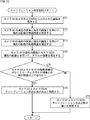
- FIG. 7 is a flowchart for explaining the details of the camera relation recognition process in step S13 of FIG.
- the feature point detector 81 (FIG. 4) detects feature points from the image supplied from the camera 12 and sets them as feature point candidates for the road sign 21.
- the feature point detection unit 81 supplies the feature amount of the feature point candidate of the road sign 21 and the two-dimensional position on the image to the matching unit 82.
- step S ⁇ b> 52 for each feature point of the road sign 21 for which the feature amount is held in the dictionary unit 80, the matching unit 82 calculates the feature amount of the feature point and the road sign 21 supplied from the feature point detection unit 81. Matching of feature quantities of feature point candidates is performed. The matching unit 82 selects a candidate feature point of the road sign 21 having the highest similarity obtained as a result of matching as a feature point of the road sign 21.
- the matching unit 82 determines whether or not a road sign is included in the image supplied from the camera 12. For example, the matching unit 82 includes a road sign in the image supplied from the camera 12 when the number of feature points whose similarity is equal to or less than a threshold is less than a predetermined number among the feature points of the selected road sign 21. If it is greater than or equal to the predetermined number, it is determined that no road sign is included.
- step S53 If it is determined in step S53 that the image supplied from the camera 12 includes a road sign, the matching unit 82 causes the estimation unit 83 to determine the two-dimensional position on the image of the feature point of the selected road sign 21. Supply.
- step S ⁇ b> 54 the estimation unit 83 determines the road for the camera 12 based on the two-dimensional position on the image of the feature point of the road sign 21 supplied from the matching unit 82 and the imaging parameter supplied from the camera 12. The three-dimensional position and orientation of the sign 21 are estimated. The estimation unit 83 supplies the estimated three-dimensional position and orientation of the road sign 21 with respect to the camera 12 to the recognition unit 87.
- step S55 the feature point detection unit 84 detects feature points from the image supplied from the camera 13 and sets them as candidate feature points of the road sign 21.
- the feature point detection unit 84 supplies the feature amount of the feature point candidate of the road sign 21 and the two-dimensional position on the image to the matching unit 85.
- step S ⁇ b> 56 for each feature point of the road sign 21 for which the feature amount is held in the dictionary unit 80, the matching unit 85 calculates the feature amount of the feature point and the road sign 21 supplied from the feature point detection unit 84. Matching of feature quantities of feature point candidates is performed. The matching unit 85 selects a feature point candidate of the road sign 21 having the highest similarity obtained as a result of matching as a feature point of the road sign 21.
- step S57 the matching unit 85 determines whether or not a road sign is included in the image supplied from the camera 13, similarly to the matching unit 82. If it is determined in step S57 that the road sign is included in the image supplied from the camera 13, the matching unit 85 uses the two-dimensional position on the image of the feature point of the selected road sign 21 to the estimation unit 86. Supply.
- step S ⁇ b> 58 the estimation unit 86 determines the road for the camera 13 based on the two-dimensional position on the image of the feature point of the road sign 21 supplied from the matching unit 85 and the imaging parameter supplied from the camera 13. The three-dimensional position and orientation of the sign 21 are estimated.
- the estimation unit 83 supplies the estimated three-dimensional position and orientation of the road sign 21 with respect to the camera 13 to the recognition unit 87.
- step S59 the recognizing unit 87 determines the three-dimensional positions and orientations of the cameras 12 and 13 based on the three-dimensional position and orientation of the road sign 21 with respect to the camera 12 and the three-dimensional position and orientation of the road sign 21 with respect to the camera 13. Recognize orientation relationships.
- the recognition unit 87 supplies the recognized relationship between the three-dimensional positions and orientations of the camera 12 and the camera 13 to the correction unit 46 in FIG. And a process returns to step S13 of FIG. 5, and progresses to step S14.
- step S53 when it is determined in step S53 that the image supplied from the camera 12 does not include a road sign, or in step S57, it is determined that the image supplied from the camera 13 does not include a road sign. If so, the process proceeds to step S18 of FIG.
- the image processing apparatus 40 has many opportunities to be imaged by the camera 12 and the camera 13 during normal use of the in-vehicle camera system 10, and the camera 12 of the road sign 21 that is a known object that exists on the road moderately. A three-dimensional position for each camera 13 is estimated. Then, the image processing apparatus 40 recognizes the relationship between the positions of the camera 12 and the camera 13 based on the three-dimensional position, and calibrates the camera 12 and the camera 13 based on the relationship.
- the calibration frequency of the camera 12 and the camera 13 can be increased as compared with the calibration that requires a special environment and equipment such as imaging of a specific pattern.
- the camera 12 is hardly affected by the shooting environment, the camera 12 and the camera 13 can be calibrated with high accuracy. Furthermore, the camera 12 and the camera 13 can be calibrated with a small amount of processing.
- the image processing apparatus 40 estimates the movement amount of the camera 12 (camera 13) using images captured at different times by the camera 12 (camera 13), and the camera 12 (camera 13) based on the movement amount. Whether or not calibration is necessary is determined.
- FIG. 8 is a diagram illustrating an overview of a second embodiment of the in-vehicle camera system to which the present disclosure is applied.
- An image processing apparatus mounted on the vehicle 11 estimates the three-dimensional position and orientation of the road sign 21 and the license plate 111 with respect to the camera 12 and the camera 13, respectively. Then, the image processing apparatus 3 of the camera 12 and the camera 13 is based on the three-dimensional position and orientation of the road sign 21 and the license plate 111 with respect to the camera 12 and the camera 13, respectively, and the estimation accuracy of the three-dimensional position and orientation. Recognize the relationship between dimension position and orientation. The image processing apparatus calibrates the camera 12 and the camera 13 based on the relationship.
- the configuration of the image processing apparatus according to the second embodiment is the same as that of the image processing apparatus 40 in FIG. Therefore, only the position detection unit 45 will be described below.
- FIG. 9 is a block diagram illustrating a configuration example of the position detection unit 45 of the in-vehicle camera system 100.
- a dictionary unit 120 includes a dictionary unit 120, a matching unit 122, an estimation unit 123, instead of the dictionary unit 80, the matching unit 82, the estimation unit 83, the matching unit 85, the estimation unit 86, and the recognition unit 87.
- 4 is different from the configuration of FIG. 4 in that a matching unit 125, an estimation unit 126, and a recognition unit 127 are provided.
- Dictionary unit 120 holds feature quantities of a plurality of feature points of road sign 21 and license plate 111 that are known objects.
- the matching unit 122 reads out feature quantities of a plurality of feature points of the road sign 21 and the license plate 111 from the dictionary unit 120. Similar to the matching unit 82 in FIG. 4, the matching unit 122 calculates the feature point of the road sign 21 from the feature point candidates supplied from the feature point detection unit 81 for each feature point of the read road sign 21. select.
- the matching unit 122 performs matching between the feature amount of the feature point read out and the feature amount of the feature point candidate supplied from the feature point detection unit 81 for each feature point of the license plate 111 that has been read.
- the matching unit 122 selects a feature point candidate having the highest similarity obtained as a result of matching as a feature point of the license plate 111.
- the matching unit 122 supplies the two-dimensional position on the image of the feature point of the selected road sign 21 and the feature point of the license plate 111 to the estimation unit 123. Further, the matching unit 122 supplies the similarity corresponding to the feature point of the selected road sign 21 and the feature point of the license plate 111 to the recognition unit 127 as the accuracy of estimation by the estimation unit 123.
- the matching unit 122 includes the road sign in the image supplied from the camera 12. 21 is determined not to exist, and nothing is supplied to the estimation unit 123. The same applies to the license plate 111.
- the estimation unit 123 is based on the two-dimensional position on the image of the feature point of the road sign 21 supplied from the matching unit 122 and the imaging parameters supplied from the camera 12. The three-dimensional position and direction of the road sign 21 with respect to the camera 12 are estimated. The estimation unit 123 supplies the estimated three-dimensional position and orientation of the road sign 21 with respect to the camera 12 to the recognition unit 127.
- the estimation unit 123 determines each feature point of the license plate 111 with respect to the camera 12 based on the two-dimensional position on the image of the feature point of the license plate 111 supplied from the matching unit 122 and the imaging parameters of the camera 12. Find the 3D position. Then, the estimation unit 123 estimates the three-dimensional position and orientation of the license plate 111 with respect to the camera 13 based on the three-dimensional position of each feature point of the license plate 111 with respect to the camera 12, and supplies it to the recognition unit 127.
- the matching unit 125 reads out feature quantities of a plurality of feature points of the road sign 21 and the license plate 111 from the dictionary unit 120. Similar to the matching unit 85 in FIG. 4, the matching unit 125 calculates the feature points of the road sign 21 from the feature point candidates supplied from the feature point detection unit 84 for each feature point of the read road sign 21. select.
- the matching unit 125 matches the feature amount of the feature point with the feature point candidate feature amount supplied from the feature point detection unit 84 for each feature point of the license plate 111 that has been read.
- the matching unit 125 selects a feature point candidate having the highest similarity obtained as a result of matching as a feature point of the license plate 111.
- the matching unit 125 supplies the estimation unit 126 with the two-dimensional positions on the image of the feature points of the selected road sign 21 and the feature points of the license plate 111. In addition, the matching unit 125 supplies the similarity corresponding to the feature point of the selected road sign 21 and the feature point of the license plate 111 to the recognition unit 127 as the accuracy of estimation by the estimation unit 126.
- the matching unit 125 when the highest similarity is equal to or less than a threshold value for a predetermined number or more of the feature points of the road sign 21, the matching unit 125 includes the road sign in the image supplied from the camera 13. 21 is determined not to exist, and nothing is supplied to the estimation unit 126. The same applies to the license plate 111.
- the estimation unit 126 is based on the two-dimensional position on the image of the feature point of the road sign 21 supplied from the matching unit 125 and the imaging parameter supplied from the camera 13. The three-dimensional position and direction of the road sign 21 with respect to the camera 13 are estimated. The estimation unit 126 supplies the estimated three-dimensional position and orientation of the road sign 21 with respect to the camera 13 to the recognition unit 127.
- the estimation unit 126 also determines the three-dimensional position of the license plate 111 relative to the camera 13 based on the two-dimensional position on the image of the feature points of the license plate 111 supplied from the matching unit 125 and the imaging parameters of the camera 13. The direction is estimated and supplied to the recognition unit 127.
- the recognition unit 127 Recognize the relationship between dimension position and orientation.
- the recognition unit 127 corresponds to the higher one of the average value of the estimation accuracy for the road sign 21 by the estimation unit 123 and the estimation unit 126 and the average value of the estimation accuracy for the license plate 111.
- the road sign 21 or the license plate 111 is selected.
- the recognition unit 127 recognizes the relationship between the three-dimensional position and orientation of the camera 12 and the camera 13 based on the three-dimensional position and orientation of the selected road sign 21 or license plate 111 with respect to the camera 12 and the camera 13, respectively.
- the recognition unit 127 sets the weight of the road sign 21 so that the higher the average value of the estimation accuracy is, the higher the average value of the estimation accuracy is based on the average value of the estimation accuracy for the road sign 21 by the estimation unit 123 and the estimation unit 126. To do. In addition, the recognition unit 127 sets the weight of the license plate 111 based on the average value of the estimation accuracy for the license plate 111 by the estimation unit 123 and the estimation unit 126 so that the higher the average value of the estimation accuracy, the higher the estimation value. To do.
- the recognition unit 127 recognizes the relationship between the three-dimensional position and the orientation of the camera 12 and the camera 13 based on the three-dimensional position and the orientation of the road sign 21 and the license plate 111 with respect to the camera 12 and the camera 13, respectively.
- the recognition unit 127 weights and adds the relationship between the three-dimensional positions and orientations of the cameras 12 and 13 recognized from the three-dimensional positions and orientations of the road sign 21 and the license plate 111 using the set weights.
- the recognition unit 127 recognizes the weighted addition result as a final relationship between the three-dimensional positions and orientations of the camera 12 and the camera 13.
- the recognition unit 127 supplies the recognized relationship between the three-dimensional positions and orientations of the camera 12 and the camera 13 to the correction unit 46 in FIG.
- the accuracy of estimation by the estimation unit 123 and the estimation unit 126 is the similarity in the matching unit 122 and the matching unit 125, respectively, but the three-dimensional position estimated by the estimation unit 123 and the estimation unit 126 It may be determined based on the direction.
- the camera relationship recognition processing by the position detection unit 45 in FIG. 9 is that the road sign 21 is replaced with the road sign 21 and the license plate 111, and the estimation accuracy by the estimation unit 123 and the estimation unit 126 in the process of step S59 is high. Except for the point used, it is the same as the camera relation recognition process of FIG. Therefore, the description is omitted.
- the recognition unit 127 performs the three-dimensional operation for each of the one camera 12 and the camera 13. Based on the position and orientation, the relationship between the three-dimensional positions and orientations of the camera 12 and the camera 13 may be recognized as in the recognition unit 87 of FIG.
- FIG. 10 is a diagram illustrating an overview of a third embodiment of the in-vehicle camera system to which the present disclosure is applied.
- the camera 141 is mounted on the rear part of the vehicle 11 and images the front of the vehicle 11. Each of the camera 12, the camera 13, and the camera 141 overlaps an imaging area with one or more other cameras.
- a road sign 21 that is a known object in front of the vehicle 11 is included in the imaging regions of the camera 12 and the camera 13.
- the imaging regions of the camera 12, the camera 13, and the camera 141 include a license plate 111 that is a known object in front of the vehicle 11.
- an image processing device mounted on the vehicle 11 estimates the three-dimensional position and orientation of the road sign 21 with respect to the camera 12 and the camera 13, respectively. Further, the image processing apparatus estimates the three-dimensional position and orientation of the license plate 111 with respect to the camera 12, the camera 13, and the camera 141, respectively.
- the image processing apparatus performs the three-dimensional position and orientation of the road sign 21 with respect to each of the camera 12 and the camera 13, the three-dimensional position and orientation of the license plate 111 with respect to each of the camera 12, the camera 13, and the camera 141, and their three-dimensional positions. Based on the estimated accuracy of the orientation, the relationship between the three-dimensional positions and orientations of the camera 12, the camera 13, and the camera 141 is recognized.
- the image processing apparatus like the image processing apparatus of the second embodiment, the three-dimensional position and direction of the road sign 21 and the license plate 111 with respect to the camera 12 and the camera 13, respectively, and the three-dimensional Based on the estimated accuracy of the position and orientation, the relationship between the three-dimensional positions and orientations of the camera 12 and the camera 13 is recognized.
- the image processing apparatus is based on the higher estimation accuracy of the three-dimensional position and orientation of the license plate 111 with respect to the camera 12 and the camera 13, respectively, and the three-dimensional position and orientation of the license plate 111 with respect to the camera 141.
- the relationship between the three-dimensional position and orientation of the camera 12 or the camera 13 and the camera 141 is recognized.
- the image processing apparatus determines whether the camera 12, the camera 13, and the camera 13 are based on the relationship between the three-dimensional position and orientation of the camera 12 and the camera 13, and the relationship of the three-dimensional position and orientation of the camera 12 or the camera 13 and the camera 141.
- the camera 141 is calibrated.
- the image processing apparatus according to the third embodiment is the same as the image processing apparatus according to the second embodiment except that the processing for the camera 141 is performed in the same manner as the processing for the camera 12 and the camera 13.
- the camera 12, the camera 12, and the camera based on the distribution of the three movement amounts without using the speed of the vehicle 11 measured by the speedometer. 13 and whether the camera 141 needs to be calibrated may be determined. In this case, it is determined that there is a need for calibration of the camera 12, the camera 13, or the camera 141 whose movement amount is an outlier of the distribution of the three movement amounts.
- FIG. 11 is a diagram illustrating an outline of the fourth embodiment of the in-vehicle camera system to which the present disclosure is applied.
- FIG. 11 differs from the configuration of the in-vehicle camera system 10 in FIG. 1 in that the camera 161 and the camera 162 are provided instead of the camera 12 and the camera 13.
- FIG. 11 is the figure which looked at the vehicle 11 from the top.
- the camera 161 (first imaging unit) and the camera 162 (second imaging unit) are mounted so that the optical axis direction is substantially perpendicular to the traveling direction of the vehicle 11.
- the camera 161 and the camera 162 are mounted on the roof on the right side of the vehicle 11.
- an image processing device mounted on the vehicle 11 performs calibration of the camera 161 and the camera 162 based on the parallax of images captured by the camera 161 and the camera 162 instead of the movement amount. Determine need.
- FIG. 12 is a block diagram illustrating a configuration example of an image processing apparatus mounted on the vehicle 11 of FIG.
- the configuration of the image processing apparatus 180 in FIG. 12 is that an estimation unit 181 is provided instead of the movement amount estimation unit 41 and the movement amount estimation unit 43, and a determination unit 182 is provided instead of the determination unit 42 and the determination unit 44. This is different from the configuration of the image processing apparatus 40 in FIG.
- the estimation unit 181 includes a movement parallax estimation unit 191, a movement parallax estimation unit 192, and a stereo parallax estimation unit 193.
- the moving parallax estimation unit 191 of the estimation unit 181 holds an image captured by the camera 161 and input from the camera 161.
- the moving parallax estimation unit 191 uses the held past (first time) image and the current (second time) image to move parallax of the current image. (Motion parallax) is estimated.
- the movement parallax estimation unit 191 supplies the estimated movement parallax to the determination unit 182.
- the moving parallax estimation unit 192 holds an image captured by the camera 162 and input from the camera 162.
- the moving parallax estimation unit 192 (second moving parallax estimation unit) uses the held past (first time) image and current (second time) image to move parallax of the current image. Is estimated.
- the movement parallax estimation unit 192 supplies the estimated movement parallax to the determination unit 182.
- the stereo parallax estimation unit 193 estimates the parallax between the two images (hereinafter referred to as stereo parallax) using the current image captured by the camera 161 and the current image captured by the camera 162. And supplied to the determination unit 182.
- the determination unit 182 needs to calibrate the cameras 161 and 162 based on the movement parallax supplied from the movement parallax estimation unit 191 and the movement parallax estimation unit 192 and the stereo parallax supplied from the stereo parallax estimation unit 193. Determine the presence or absence of sex.
- the determination unit 182 supplies the determination result to the position detection unit 45.
- Image processing of the image processing apparatus 180 of FIG. 12 is the same as the image processing of FIG. 5 except that the camera 12 and the camera 13 are replaced with the camera 161 and the camera 162 and the calibration determination process. Therefore, only the calibration determination process will be described below.
- FIG. 13 is a flowchart for explaining the calibration determination process of the image processing apparatus 180.
- step S72 the moving parallax estimating unit 191 estimates the moving parallax of the current image using the past image and the current image of the camera 161 that is held, and supplies the estimated moving parallax to the determining unit 182.
- step S73 the moving parallax estimation unit 192 estimates the moving parallax of the current image using the held past image and the current image of the camera 162, and supplies the estimated moving parallax to the determination unit 182.
- step S74 the stereo parallax estimation unit 193 estimates the stereo parallax using the current image of the camera 161 and the current image of the camera 162, and supplies the stereo parallax to the determination unit 182.
- step S75 the determination unit 182 has a difference between at least one of the movement parallax supplied from the movement parallax estimation unit 191 and the movement parallax estimation unit 192 and the stereo parallax supplied from the stereo parallax estimation unit 193 equal to or greater than a threshold value. Determine whether or not.
- step S76 the determination unit 182 determines that there is a need for calibration of the camera 161 and the camera 162, and supplies the determination result to the position detection unit 45. . Then, the calibration determination process ends.
- step S77 the determination unit 182 determines that there is no need for calibration of the camera 161 and the camera 162, and supplies the determination result to the position detection unit 45.
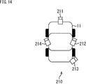
- FIG. 14 is a diagram illustrating an overview of a fifth embodiment of the in-vehicle camera system to which the present disclosure is applied.
- FIG. 14 is a view of the vehicle 11 as viewed from above.
- the cameras 211 to 214 are mounted on the front, right side, rear and left sides of the roof of the vehicle 11, respectively.
- An image processing apparatus (not shown) mounted on the vehicle 11 performs the same processing as in the first to third embodiments for each of the cameras 211 to 214 and calibrates the cameras 211 to 214.
- the cameras 211 to are based on the distribution of the four movement amounts.
- the presence / absence of necessity of calibration 214 may be determined.
- ⁇ Sixth embodiment> (Description of computer to which the present disclosure is applied)
- the series of processes of the image processing apparatus described above can be executed by hardware or can be executed by software.
- a program constituting the software is installed in the computer.
- the computer includes, for example, a general-purpose personal computer capable of executing various functions by installing various programs by installing a computer incorporated in dedicated hardware.
- FIG. 15 is a block diagram showing an example of the hardware configuration of a computer that executes the above-described series of processing by a program.
- a CPU Central Processing Unit
- ROM Read Only Memory
- RAM Random Access Memory
- An input / output interface 305 is further connected to the bus 304.
- An input unit 306, an output unit 307, a storage unit 308, a communication unit 309, and a drive 310 are connected to the input / output interface 305.
- the input unit 306 includes a keyboard, a mouse, a microphone, and the like.
- the output unit 307 includes a display, a speaker, and the like.
- the storage unit 308 includes a hard disk, a nonvolatile memory, and the like.
- the communication unit 309 includes a network interface and the like.
- the drive 310 drives a removable medium 311 such as a magnetic disk, an optical disk, a magneto-optical disk, or a semiconductor memory.
- the CPU 301 loads the program stored in the storage unit 308 to the RAM 303 via the input / output interface 305 and the bus 304 and executes the program. A series of processing is performed.
- the program executed by the computer 300 can be provided by being recorded on a removable medium 311 as a package medium, for example.
- the program can be provided via a wired or wireless transmission medium such as a local area network, the Internet, or digital satellite broadcasting.
- the program can be installed in the storage unit 308 via the input / output interface 305 by attaching the removable medium 311 to the drive 310. Further, the program can be received by the communication unit 309 via a wired or wireless transmission medium and installed in the storage unit 308. In addition, the program can be installed in advance in the ROM 302 or the storage unit 308.
- the program executed by the computer 300 may be a program that is processed in time series in the order described in this specification, or a necessary timing such as when the call is performed in parallel. It may be a program in which processing is performed.
- FIG. 16 is a block diagram illustrating an example of a schematic configuration of a vehicle control system to which the present disclosure is applied.
- the vehicle control system 2000 includes a plurality of electronic control units connected via a communication network 2010.
- the vehicle control system 2000 includes a drive system control unit 2100, a body system control unit 2200, a battery control unit 2300, a vehicle exterior information detection unit 2400, a vehicle interior information detection unit 2500, and an integrated control unit 2600.
- the communication network 2010 that connects these multiple control units conforms to any standard such as CAN (Controller Area Network), LIN (Local Interconnect Network), LAN (Local Area Network), or FlexRay (registered trademark). It may be an in-vehicle communication network.
- Each control unit includes a microcomputer that performs arithmetic processing according to various programs, a storage unit that stores programs executed by the microcomputer or parameters used for various calculations, and a drive circuit that drives various devices to be controlled. Is provided.
- Each control unit includes a network I / F for performing communication with other control units via the communication network 2010, and wired or wireless communication with devices or sensors inside and outside the vehicle. A communication I / F for performing communication is provided. In FIG.
- a microcomputer 2610 As a functional configuration of the integrated control unit 2600, a microcomputer 2610, a general-purpose communication I / F 2620, a dedicated communication I / F 2630, a positioning unit 2640, a beacon receiving unit 2650, an in-vehicle device I / F 2660, an audio image output unit 2670, An in-vehicle network I / F 2680 and a storage unit 2690 are illustrated.
- other control units include a microcomputer, a communication I / F, a storage unit, and the like.
- the drive system control unit 2100 controls the operation of devices related to the drive system of the vehicle according to various programs.
- the drive system control unit 2100 includes a driving force generator for generating a driving force of a vehicle such as an internal combustion engine or a driving motor, a driving force transmission mechanism for transmitting the driving force to wheels, and a steering angle of the vehicle. It functions as a control device such as a steering mechanism that adjusts and a braking device that generates a braking force of the vehicle.
- the drive system control unit 2100 may have a function as a control device such as ABS (Antilock Brake System) or ESC (Electronic Stability Control).
- a vehicle state detection unit 2110 is connected to the drive system control unit 2100.
- the vehicle state detection unit 2110 includes, for example, a gyro sensor that detects the angular velocity of the axial rotation of the vehicle body, an acceleration sensor that detects the acceleration of the vehicle, or an operation amount of an accelerator pedal, an operation amount of a brake pedal, and steering of a steering wheel. At least one of sensors for detecting an angle, an engine speed, a rotational speed of a wheel, or the like is included.
- the drive system control unit 2100 performs arithmetic processing using a signal input from the vehicle state detection unit 2110, and controls an internal combustion engine, a drive motor, an electric power steering device, a brake device, or the like.
- the body system control unit 2200 controls the operation of various devices mounted on the vehicle body according to various programs.
- the body system control unit 2200 functions as a keyless entry system, a smart key system, a power window device, or a control device for various lamps such as a headlamp, a back lamp, a brake lamp, a blinker, or a fog lamp.
- the body control unit 2200 can be input with radio waves transmitted from a portable device that substitutes for a key or signals of various switches.
- the body system control unit 2200 receives the input of these radio waves or signals, and controls the vehicle door lock device, power window device, lamp, and the like.
- the battery control unit 2300 controls the secondary battery 2310 that is a power supply source of the drive motor according to various programs. For example, information such as battery temperature, battery output voltage, or remaining battery capacity is input to the battery control unit 2300 from a battery device including the secondary battery 2310. The battery control unit 2300 performs arithmetic processing using these signals, and controls the temperature adjustment control of the secondary battery 2310 or the cooling device provided in the battery device.
- the outside information detection unit 2400 detects information outside the vehicle on which the vehicle control system 2000 is mounted.
- the vehicle exterior information detection unit 2400 is connected to at least one of the imaging unit 2410 and the vehicle exterior information detection unit 2420.
- the imaging unit 2410 includes at least one of a ToF (Time Of Flight) camera, a stereo camera, a monocular camera, an infrared camera, and other cameras.
- the outside information detection unit 2420 detects, for example, current weather or an environmental sensor for detecting weather, or other vehicles, obstacles, pedestrians, etc. around the vehicle on which the vehicle control system 2000 is mounted. A surrounding information detection sensor is included.
- the environmental sensor may be, for example, at least one of a raindrop sensor that detects rainy weather, a fog sensor that detects fog, a sunshine sensor that detects sunlight intensity, and a snow sensor that detects snowfall.
- the ambient information detection sensor may be at least one of an ultrasonic sensor, a radar device, and a LIDAR (Light Detection and Ranging, Laser Imaging Detection and Ranging) device.
- the imaging unit 2410 and the outside information detection unit 2420 may be provided as independent sensors or devices, or may be provided as a device in which a plurality of sensors or devices are integrated.
- FIG. 17 shows an example of installation positions of the imaging unit 2410 and the vehicle exterior information detection unit 2420.
- the imaging units 2910, 2912, 2914, 2916, and 2918 are provided at, for example, at least one position among a front nose, a side mirror, a rear bumper, a back door, and an upper portion of a windshield in the vehicle interior of the vehicle 2900.
- An imaging unit 2910 provided in the front nose and an imaging unit 2918 provided in the upper part of the windshield in the vehicle interior mainly acquire an image in front of the vehicle 2900.
- the imaging units 2912 and 2914 provided in the side mirror mainly acquire an image on the side of the vehicle 2900.
- An imaging unit 2916 provided in the rear bumper or the back door mainly acquires an image behind the vehicle 2900.
- An imaging unit 2918 provided on the upper part of the windshield in the passenger compartment is mainly used for detecting a preceding vehicle or a pedestrian, an obstacle, a traffic light, a traffic sign, a lane, or the like.
- FIG. 17 shows an example of shooting ranges of the respective imaging units 2910, 2912, 2914, and 2916.
- the imaging range a indicates the imaging range of the imaging unit 2910 provided in the front nose
- the imaging ranges b and c indicate the imaging ranges of the imaging units 2912 and 2914 provided in the side mirrors, respectively
- the imaging range d The imaging range of the imaging unit 2916 provided in the rear bumper or the back door is shown. For example, by superimposing the image data captured by the imaging units 2910, 2912, 2914, and 2916, an overhead image when the vehicle 2900 is viewed from above is obtained.
- the vehicle outside information detection units 2920, 2922, 2924, 2926, 2928, 2930 provided on the front, rear, side, corner, and upper windshield of the vehicle 2900 may be, for example, an ultrasonic sensor or a radar device.
- the vehicle outside information detection units 2920, 2926, and 2930 provided on the front nose, the rear bumper, the back door, and the windshield in the vehicle interior of the vehicle 2900 may be, for example, LIDAR devices.
- These vehicle outside information detection units 2920 to 2930 are mainly used for detecting a preceding vehicle, a pedestrian, an obstacle, and the like.
- the vehicle outside information detection unit 2400 causes the imaging unit 2410 to capture an image outside the vehicle and receives the captured image data.
- the vehicle exterior information detection unit 2400 receives detection information from the vehicle exterior information detection unit 2420 connected thereto.
- the vehicle outside information detection unit 2420 is an ultrasonic sensor, a radar device, or a LIDAR device
- the vehicle outside information detection unit 2400 transmits ultrasonic waves, electromagnetic waves, or the like, and receives received reflected wave information.
- the outside information detection unit 2400 may perform object detection processing or distance detection processing such as a person, a vehicle, an obstacle, a sign, or a character on a road surface based on the received information.
- the vehicle outside information detection unit 2400 may perform environment recognition processing for recognizing rainfall, fog, road surface conditions, or the like based on the received information.
- the vehicle outside information detection unit 2400 may calculate a distance to an object outside the vehicle based on the received information.
- the outside information detection unit 2400 may perform image recognition processing or distance detection processing for recognizing a person, a vehicle, an obstacle, a sign, a character on a road surface, or the like based on the received image data.
- the vehicle exterior information detection unit 2400 performs processing such as distortion correction or alignment on the received image data, and combines the image data captured by the different imaging units 2410 to generate an overhead image or a panoramic image. Also good.
- the vehicle exterior information detection unit 2400 may perform viewpoint conversion processing using image data captured by different imaging units 2410.
- the in-vehicle information detection unit 2500 detects in-vehicle information.
- a driver state detection unit 2510 that detects the driver's state is connected to the in-vehicle information detection unit 2500.
- the driver state detection unit 2510 may include a camera that captures an image of the driver, a biological sensor that detects biological information of the driver, a microphone that collects sound in the passenger compartment, and the like.
- the biometric sensor is provided, for example, on a seat surface or a steering wheel, and detects biometric information of an occupant sitting on the seat or a driver holding the steering wheel.
- the vehicle interior information detection unit 2500 may calculate the degree of fatigue or concentration of the driver based on the detection information input from the driver state detection unit 2510, and determines whether the driver is asleep. May be.
- the vehicle interior information detection unit 2500 may perform a process such as a noise canceling process on the collected audio signal.
- the integrated control unit 2600 controls the overall operation in the vehicle control system 2000 according to various programs.
- An input unit 2800 is connected to the integrated control unit 2600.
- the input unit 2800 is realized by a device that can be input by a passenger, such as a touch panel, a button, a microphone, a switch, or a lever.
- the input unit 2800 may be, for example, a remote control device using infrared rays or other radio waves, or may be an external connection device such as a mobile phone or a PDA (Personal Digital Assistant) that supports the operation of the vehicle control system 2000. May be.
- the input unit 2800 may be, for example, a camera. In this case, the passenger can input information using a gesture.
- the input unit 2800 may include, for example, an input control circuit that generates an input signal based on information input by a passenger or the like using the input unit 2800 and outputs the input signal to the integrated control unit 2600.
- a passenger or the like operates the input unit 2800 to input various data or instruct a processing operation to the vehicle control system 2000.
- the storage unit 2690 may include a RAM (Random Access Memory) that stores various programs executed by the microcomputer, and a ROM (Read Only Memory) that stores various parameters, calculation results, sensor values, and the like.
- the storage unit 2690 may be realized by a magnetic storage device such as an HDD (Hard Disc Drive), a semiconductor storage device, an optical storage device, a magneto-optical storage device, or the like.
- General-purpose communication I / F 2620 is a general-purpose communication I / F that mediates communication with various devices existing in the external environment 2750.
- the general-purpose communication I / F 2620 is a cellular communication protocol such as GSM (registered trademark) (Global System of Mobile communications), WiMAX, LTE (Long Term Evolution) or LTE-A (LTE-Advanced), or a wireless LAN (Wi-Fi). (Also referred to as (registered trademark)) may be implemented.
- the general-purpose communication I / F 2620 is connected to a device (for example, an application server or a control server) existing on an external network (for example, the Internet, a cloud network, or an operator-specific network) via, for example, a base station or an access point. May be. Further, the general-purpose communication I / F 2620 is connected to a terminal (for example, a pedestrian or a store terminal, or an MTC (Machine Type Communication) terminal) that exists in the vicinity of the vehicle using, for example, P2P (Peer To Peer) technology. May be.
- a terminal for example, a pedestrian or a store terminal, or an MTC (Machine Type Communication) terminal
- P2P Peer To Peer
- the dedicated communication I / F 2630 is a communication I / F that supports a communication protocol formulated for use in a vehicle.
- the dedicated communication I / F 2630 may implement a standard protocol such as WAVE (Wireless Access in Vehicle Environment) or DSRC (Dedicated Short Range Communications) which is a combination of the lower layer IEEE 802.11p and the upper layer IEEE 1609. .
- the dedicated communication I / F 2630 is typically a V2X concept that includes one or more of vehicle-to-vehicle communication, vehicle-to-infrastructure communication, and vehicle-to-pedestrian communication. Perform communication.
- the positioning unit 2640 receives, for example, a GNSS signal from a GNSS (Global Navigation Satellite System) satellite (for example, a GPS signal from a GPS (Global Positioning System) satellite), performs positioning, and performs latitude, longitude, and altitude of the vehicle.
- the position information including is generated.
- the positioning unit 2640 may specify the current position by exchanging signals with the wireless access point, or may acquire position information from a terminal such as a mobile phone, PHS, or smartphone having a positioning function.
- the beacon receiving unit 2650 receives, for example, radio waves or electromagnetic waves transmitted from radio stations installed on the road, and acquires information such as the current position, traffic jams, closed roads, or required time. Note that the function of the beacon receiving unit 2650 may be included in the dedicated communication I / F 2630 described above.
- the in-vehicle device I / F 2660 is a communication interface that mediates connections between the microcomputer 2610 and various devices existing in the vehicle.
- the in-vehicle device I / F 2660 may establish a wireless connection using a wireless communication protocol such as a wireless LAN, Bluetooth (registered trademark), NFC (Near Field Communication), or WUSB (Wireless USB).
- the in-vehicle device I / F 2660 may establish a wired connection via a connection terminal (and a cable if necessary).
- the in-vehicle device I / F 2660 exchanges a control signal or a data signal with, for example, a mobile device or wearable device that a passenger has, or an information device that is carried in or attached to the vehicle.
- the in-vehicle network I / F 2680 is an interface that mediates communication between the microcomputer 2610 and the communication network 2010.
- the in-vehicle network I / F 2680 transmits and receives signals and the like in accordance with a predetermined protocol supported by the communication network 2010.
- the microcomputer 2610 of the integrated control unit 2600 is connected via at least one of a general-purpose communication I / F 2620, a dedicated communication I / F 2630, a positioning unit 2640, a beacon receiving unit 2650, an in-vehicle device I / F 2660, and an in-vehicle network I / F 2680.
- the vehicle control system 2000 is controlled according to various programs.
- the microcomputer 2610 calculates a control target value of the driving force generation device, the steering mechanism, or the braking device based on the acquired information inside and outside the vehicle, and outputs a control command to the drive system control unit 2100. Also good.
- the microcomputer 2610 may perform cooperative control for the purpose of avoiding or reducing the collision of a vehicle, following traveling based on the inter-vehicle distance, traveling at a vehicle speed, automatic driving, and the like.
- the microcomputer 2610 is information acquired via at least one of the general-purpose communication I / F 2620, the dedicated communication I / F 2630, the positioning unit 2640, the beacon receiving unit 2650, the in-vehicle device I / F 2660, and the in-vehicle network I / F 2680. Based on the above, local map information including peripheral information on the current position of the vehicle may be created. Further, the microcomputer 2610 may generate a warning signal by predicting a danger such as collision of a vehicle, approach of a pedestrian or the like or approach to a closed road based on the acquired information. The warning signal may be, for example, a signal for generating a warning sound or lighting a warning lamp.
- the sound image output unit 2670 transmits an output signal of at least one of sound and image to an output device capable of visually or audibly notifying information to a vehicle occupant or outside the vehicle.
- an audio speaker 2710, a display unit 2720, and an instrument panel 2730 are illustrated as output devices.
- the display unit 2720 may include at least one of an on-board display and a head-up display, for example.
- the display unit 2720 may have an AR (Augmented Reality) display function.
- the output device may be another device such as a headphone, a projector, or a lamp other than these devices.
- the display device can display the results obtained by various processes performed by the microcomputer 2610 or information received from other control units in various formats such as text, images, tables, and graphs. Display visually. Further, when the output device is an audio output device, the audio output device converts an audio signal made up of reproduced audio data or acoustic data into an analog signal and outputs it aurally.
- At least two control units connected via the communication network 2010 may be integrated as one control unit.
- each control unit may be configured by a plurality of control units.
- the vehicle control system 2000 may include another control unit not shown.
- some or all of the functions of any of the control units may be given to other control units.
- the predetermined arithmetic processing may be performed by any one of the control units.
- a sensor or device connected to one of the control units may be connected to another control unit, and a plurality of control units may transmit / receive detection information to / from each other via the communication network 2010. .
- the integrated control unit 2600 is provided with the function of the image processing apparatus of the present application.
- the functions of the image processing apparatus of the present application may be realized by a module for the integrated control unit 2600 (for example, an integrated circuit module configured by one die).
- the image processing apparatus of the present application may be realized by a plurality of control units.
- the system means a set of a plurality of components (devices, modules (parts), etc.), and it does not matter whether all the components are in the same housing. Accordingly, a plurality of devices housed in separate housings and connected via a network and a single device housing a plurality of modules in one housing are all systems. .
- the number and arrangement of cameras (imaging units) constituting the in-vehicle camera system are not limited to the above-described number and arrangement.
- the present technology can also be applied to an in-vehicle camera system mounted on a vehicle such as an electric vehicle other than an automobile, a hybrid electric vehicle, or a motorcycle.
- the method for estimating the three-dimensional position and orientation of a known object is not limited to the method described above.
- the camera may be calibrated based only on the three-dimensional position of the known object.
- this indication can also take the following structures.
- An estimation unit that estimates a three-dimensional position of each known object included in each image captured by a plurality of imaging units with respect to each imaging unit;
- a recognition unit for recognizing a positional relationship between the plurality of imaging units based on a three-dimensional position of each of the known objects estimated by the estimation unit;
- An image processing apparatus comprising: a correction unit that corrects the images captured by the plurality of imaging units based on the positional relationship recognized by the recognition unit.
- the estimation unit estimates a three-dimensional position and orientation of the known object with respect to each imaging unit;
- the recognizing unit recognizes the relationship between the positions and orientations of the plurality of imaging units based on the three-dimensional positions and orientations of the known objects estimated by the estimating unit with respect to the imaging units;
- the image processing apparatus according to (1), wherein the correction unit is configured to correct the image based on a relationship between the position and orientation recognized by the recognition unit.
- the estimation unit estimates a three-dimensional position of the known object with respect to the imaging unit based on a position of the feature point of the known object on the image and a parameter of the imaging unit for each imaging unit.
- the image processing apparatus according to (1) configured.
- the number of the known objects is plural,
- the recognition unit is configured to recognize a positional relationship between the plurality of imaging units based on the estimation accuracy of the three-dimensional position of each known object estimated by the estimation unit and the three-dimensional position of each known object.
- the image processing apparatus according to (1) or (3).
- the plurality of imaging units are mounted on a vehicle,
- the image processing apparatus according to any one of (1) to (4), wherein the known object is an object on a road or an object included in a vehicle.
- the image processing device An estimation step for estimating a three-dimensional position of each known image object included in each image captured by a plurality of image capturing units; A recognition step of recognizing a positional relationship of the plurality of imaging units based on a three-dimensional position of the known object with respect to each imaging unit estimated by the estimation step; An image processing method comprising: a correction step of correcting the images captured by the plurality of imaging units based on the positional relationship recognized by the processing of the recognition step.
- An estimation unit that estimates a three-dimensional position of each known object included in each image captured by a plurality of imaging units with respect to each imaging unit;
- a recognition unit for recognizing a positional relationship between the plurality of imaging units based on a three-dimensional position of each of the known objects estimated by the estimation unit;
- a program for functioning as a correction unit that corrects the images captured by the plurality of imaging units based on the positional relationship recognized by the recognition unit.
Abstract
本開示は、複数の撮像部により撮像された画像内の既知物体を用いて、高精度でカメラのキャリブレーションを行うことができるようにする画像処理装置、画像処理方法、およびプログラムに関する。 推定部は、複数のカメラにより撮像された各画像内に含まれる道路標識の各カメラに対する3次元位置を推定する。認識部は、推定部により推定された道路標識の各カメラに対する3次元位置に基づいて、複数のカメラの位置の関係を認識する。認識部により認識された複数のカメラの位置の関係は、複数のカメラにより撮像された画像の補正に用いられる。本開示は、例えば、画像処理装置等に適用することができる。
Description
本開示は、画像処理装置、画像処理方法、およびプログラムに関し、特に、複数の撮像部により撮像された画像内の既知物体を用いて、高精度でカメラのキャリブレーションを行うことができるようにした画像処理装置、画像処理方法、およびプログラムに関する。
複数のカメラにより撮像された画像を連携させて画像処理を行う際、カメラどうしの3次元位置および向き(姿勢)の関係を高精度で制御することは重要である。また、カメラどうしの3次元位置や向きの関係は、衝撃、温度、経年等によって変化するため、これらの関係の制御パラメータは定期的に更新する必要がある。
カメラどうしの3次元位置や向きの関係が所定の関係となるように制御する方法として、カメラにより撮像された画像を補正する方法が知られている。画像の補正に用いられるパラメータを決定する方法、即ちカメラをキャリブレーションする方法としては、例えば各カメラで特定パターンを撮像し、その結果得られる画像が所望の画像となるように補正するためのパラメータを求める方法がある。この方法では、特定パターンを撮像する必要があるため、定期的にパラメータを更新することは困難である。
そこで、特定パターンを用いずに、通常使用時に複数のカメラにより撮像された画像を用いて、各画像内の既知物体の類似度が高くなるようにパラメータを決定する方法が考案されている(例えば、特許文献1参照)。この方法では、通常使用時にパラメータを決定することができるため、定期的にパラメータを更新することができる。また、任意のシーンを撮像することによりパラメータを決定する方法も考案されている。
しかしながら、上述した特定パターンを用いない方法では、撮影環境等の影響を受けやすく、十分な精度でカメラのキャリブレーションを行うことはできなかった。
本開示は、このような状況に鑑みてなされたものであり、複数の撮像部により撮像された画像内の既知物体を用いて、高精度でカメラのキャリブレーションを行うことができるようにするものである。
本開示の一側面の画像処理装置は、複数の撮像部により撮像された各画像内に含まれる既知物体の各撮像部に対する3次元位置を推定する推定部と、前記推定部により推定された前記既知物体の各撮像部に対する3次元位置に基づいて、前記複数の撮像部の位置の関係を認識する認識部と、前記認識部により認識された前記位置の関係に基づいて、前記複数の撮像部により撮像された前記画像を補正する補正部とを備える画像処理装置である。
本開示の一側面の画像処理方法およびプログラムは、本開示の一側面の画像処理装置に対応する。
本開示の一側面においては、複数の撮像部により撮像された各画像内に含まれる既知物体の各撮像部に対する3次元位置が推定され、推定された前記既知物体の各撮像部に対する3次元位置に基づいて、前記複数の撮像部の位置の関係が認識され、認識された前記位置の関係に基づいて、前記複数の撮像部により撮像された前記画像が補正される。
本開示の一側面によれば、画像処理を行うことができる。また、本開示の一側面によれば、複数の撮像部により撮像された画像内の既知物体を用いて、高精度でカメラのキャリブレーションを行うことができる。
なお、ここに記載された効果は必ずしも限定されるものではなく、本開示中に記載されたいずれかの効果であってもよい。
以下、本開示を実施するための形態(以下、実施の形態という)について説明する。なお、説明は以下の順序で行う。
1.第1実施の形態:車載カメラシステム(図1乃至図7)
2.第2実施の形態:車載カメラシステム(図8および図9)
3.第3実施の形態:車載カメラシステム(図10)
4.第4実施の形態:車載カメラシステム(図11乃至図13)
5.第5実施の形態:車載カメラシステム(図14)
6.第6実施の形態:コンピュータ(図15)
7.第7実施の形態:車両制御システム(図16および図17)
1.第1実施の形態:車載カメラシステム(図1乃至図7)
2.第2実施の形態:車載カメラシステム(図8および図9)
3.第3実施の形態:車載カメラシステム(図10)
4.第4実施の形態:車載カメラシステム(図11乃至図13)
5.第5実施の形態:車載カメラシステム(図14)
6.第6実施の形態:コンピュータ(図15)
7.第7実施の形態:車両制御システム(図16および図17)
<第1実施の形態>
(車載カメラシステムの第1実施の形態の概要)
図1は、本開示を適用した車載カメラシステムの第1実施の形態の概要を示す図である。
(車載カメラシステムの第1実施の形態の概要)
図1は、本開示を適用した車載カメラシステムの第1実施の形態の概要を示す図である。
図1の車載カメラシステム10は、自動車の車両11、カメラ12、カメラ13等により構成される。なお、本明細書では、通常運転時の車両11の進行方向に向かって、前方、後方、右側、左側を、それぞれ、車両11の前方、後方、右側、左側という。
カメラ12(第1の撮像部)とカメラ13(第2の撮像部)は、車両11の屋根の前方に、撮像領域が重複するように搭載される。図1の例では、カメラ12とカメラ13の撮像領域に、車両11の前方の既知物体である道路標識21が含まれている。
第1実施の形態では、道路標識21が既知物体とされるが、既知物体は、サイズおよび形状が既知の物体であれば、道路標識以外の道路上の物体、または、ナンバープレート、エンブレムなどの車両11または他の車両が有する物体などであってもよい。
車両11に搭載された図示せぬ画像処理装置は、カメラ12とカメラ13それぞれに対する道路標識21の3次元位置および向きを推定する。
なお、カメラ12(カメラ13)に対する3次元位置とは、例えば、カメラ12(カメラ13)の撮像面の所定の位置(例えば中央)を原点とし、その撮像面の水平方向および垂直方向、並びに、撮像面に垂直な方向を、それぞれ、x方向、y方向、z方向としたときの、x方向、y方向、およびz方向の位置である。また、カメラ12(カメラ13)に対する向きとは、例えば、このx方向、y方向、およびz方向を軸としたときの回転角である。
画像処理装置は、カメラ12とカメラ13それぞれに対する道路標識21の3次元位置および向きに基づいて、カメラ12とカメラ13の3次元位置および向きの関係を認識し、その関係に基づいてカメラ12とカメラ13のキャリブレーションを行う。
カメラ12とカメラ13の3次元位置の関係とは、例えば、カメラ12またはカメラ13の一方の撮像面の所定の位置(例えば中央)を原点とし、その撮像面の水平方向および垂直方向、並びに、撮像面に垂直な方向を、それぞれ、x方向、y方向、z方向としたときの、他方の撮像面の所定の位置のx方向、y方向、およびz方向の位置である。また、カメラ12とカメラ13の向きの関係とは、例えば、このx方向、y方向、およびz方向を軸としたときの他方の撮像面の回転角である。
(画像処理装置の構成例)
図2は、図1の車両11に搭載される画像処理装置の構成例を示すブロック図である。
図2は、図1の車両11に搭載される画像処理装置の構成例を示すブロック図である。
図2の画像処理装置40は、移動量推定部41、判定部42、移動量推定部43、判定部44、位置検出部45、および補正部46により構成される。
画像処理装置40には、カメラ12およびカメラ13により撮像された画像が入力される。カメラ12により撮像された画像は、移動量推定部41、移動量推定部43、位置検出部45、および補正部46に供給され、カメラ13により撮像された画像は、移動量推定部41、移動量推定部43、位置検出部45、および補正部46に供給される。また、画像処理装置40には、カメラ12およびカメラ13のそれぞれから、撮像パラメータが入力され、位置検出部45に供給される。
なお、撮像パラメータとは、例えば、焦点距離、画素サイズなどに基づいて算出される水平方向および垂直方向の拡大率などの内部パラメータであり、画像上の位置を実世界の3次元空間上の位置に変換する際に用いられるパラメータである。内部パラメータの詳細は、例えば、特許文献1に記載されている。
画像処理装置40の移動量推定部41は、カメラ12から供給される異なる時刻(フレーム)の画像を用いて、その時刻の間のカメラ12の3次元位置および向きの移動量を推定し、判定部42に供給する。
判定部42は、移動量推定部41から供給される移動量と、車両11に搭載された図示せぬ速度計により計測された車両11の速度とに基づいて、カメラ12のキャリブレーションの必要性の有無を判定する。判定部42は、判定結果を位置検出部45と補正部46に供給する。
移動量推定部43は、カメラ13から供給される異なる時刻の画像を用いて、その時刻の間のカメラ13の3次元位置および向きの移動量を推定し、判定部44に供給する。
判定部44は、移動量推定部43から供給される移動量と、車両11に搭載された図示せぬ速度計により計測された車両11の速度とに基づいて、カメラ13のキャリブレーションの必要性の有無を判定する。判定部44は、判定結果を位置検出部45と補正部46に供給する。
位置検出部45は、判定部42と判定部44の少なくとも一方から供給される判定結果が必要性有りという判定結果である場合、カメラ12とカメラ13から供給される画像に含まれる共通の既知物体として道路標識21を検出する。
そして、位置検出部45は、カメラ12およびカメラ13のそれぞれから供給される撮像パラメータに基づいて、カメラ12およびカメラ13それぞれに対する道路標識21の3次元位置および向きを推定する。位置検出部45は、その3次元位置および向きに基づいてカメラ12とカメラ13の3次元位置および向きの関係を認識する。位置検出部45は、その関係を補正部46に供給する。
補正部46は、位置検出部45から供給されるカメラ12とカメラ13の関係と、判定部42および判定部44から供給される判定結果とに基づいて、カメラ12とカメラ13の少なくとも一方の画像の補正に用いられる補正パラメータを決定し、保持(更新)する。補正部46は、保持されている補正パラメータを用いて、カメラ12とカメラ13から供給される画像を補正し、補正後の画像を出力する。また、保持されているカメラ12の補正パラメータは、移動量推定部41により読み出され、カメラ12の移動量を推定する際に用いられる。保持されているカメラ13の補正パラメータは、移動量推定部43により読み出され、カメラ13の移動量を推定する際に用いられる。
補正パラメータは、例えば、カメラ12とカメラ13の向き、並びに、y方向およびz方向の位置が同一になるように決定することができる。この場合、カメラ12とカメラ13により撮像された画像は、補正部46の補正により平行になる。
(移動量推定部の構成例)
図3は、図2の移動量推定部41の構成例を示すブロック図である。
図3は、図2の移動量推定部41の構成例を示すブロック図である。
移動量推定部41は、画像補正部61、画像補正部62、特徴点検出部63、視差検出部64、位置算出部65、特徴量算出部66、マップ情報記憶部67、動きマッチング部68、および移動量算出部69により構成される。
画像補正部61は、図2の補正部46に保持されているカメラ12の補正パラメータに基づいて、カメラ12から供給される画像を、カメラ13から供給される画像と同じ方向を向いた画像となるように補正する。画像補正部61は、補正後の画像を左画像として視差検出部64と動きマッチング部68に供給する。
画像補正部62は、図2の補正部46に保持されているカメラ13の補正パラメータに基づいて、カメラ13から供給される画像を、カメラ12から供給される画像と同じ方向を向いた画像となるように補正する。画像補正部62は、補正後の画像を右画像として特徴点検出部63に供給する。
特徴点検出部63は、画像補正部62から供給される右画像の特徴点を検出する。特徴点検出部63は、検出された各特徴点の右画像上の位置を示す右特徴点位置情報と右画像を、視差検出部64および特徴量算出部66に供給する。
視差検出部64は、特徴点検出部63から供給される右特徴点位置情報と右画像とに基づいて、画像補正部61から供給される左画像から、右画像の各特徴点に対応する特徴点を検出する。視差検出部64は、検出された各特徴点の左画像上の位置を示す左特徴点位置情報と右特徴点位置情報を位置算出部65に供給する。また、視差検出部64は、特徴点ごとに、右特徴点位置情報が示す位置と左特徴点位置情報が示す位置との差をステレオ視差として検出し、各特徴点のステレオ視差を位置算出部65に供給する。
位置算出部65は、視差検出部64から供給されるステレオ視差、右特徴点位置情報、および左特徴点位置情報に基づいて、各特徴点の実世界の3次元空間上の位置を算出する。位置算出部65は、各特徴点の実世界の3次元空間上の位置を示す3次元位置情報を特徴量算出部66に供給する。
特徴量算出部66は、特徴点検出部63から供給される右特徴点位置情報と右画像に基づいて、各特徴点の特徴量を算出する。特徴量算出部66は、各特徴点の3次元位置情報と特徴量を含む特徴点情報を、マップ情報記憶部67に記憶させる。
動きマッチング部68は、過去の左画像および右画像から検出された各特徴点の特徴点情報をマップ情報記憶部67から読み出す。動きマッチング部68は、読み出された特徴点情報に含まれる各特徴点の特徴量に基づいて、画像補正部61から供給される現在の左画像から、その特徴点に対応する特徴点を検出する。動きマッチング部68は、読み出された特徴点情報に含まれる各特徴点の3次元位置情報と、その特徴点に対応する左特徴点位置情報を、移動量算出部69に供給する。
移動量算出部69は、動きマッチング部68から供給される過去の各特徴点の3次元位置情報と、その特徴点に対応する現在の特徴点の左特徴点位置情報とに基づいて、フレーム間のカメラ12の3次元位置および向きの移動量を推定する。移動量算出部69は、推定された移動量を図2の判定部42に供給する。
なお、図3の移動量推定部41では、ステレオ視差に基づいて各特徴点の3次元位置が算出されるようにしたが、移動視差に基づいて各特徴点の3次元位置が算出されるようにしてもよい。この場合、視差検出部64は、異なる時刻の左画像(右画像)を用いて、左画像(右画像)の各特徴点の移動視差を検出する。そして、位置算出部65は、視差検出部64により検出された移動視差と左特徴点位置情報(右特徴点位置情報)に基づいて、各特徴点の3次元位置を算出する。
また、図示は省略するが、移動量推定部43の構成は、動きマッチング部68に左画像ではなく右画像が入力される点を除いて、図3の移動量推定部41の構成と同様である。なお、ここでは、移動量推定部41および判定部42と、移動量推定部43および判定部44が、別々に設けられ、カメラ12とカメラ13のキャリブレーションの必要性の有無が別々に判定されるようにするが、移動量推定部41が図3で示すように構成される場合、カメラ12およびカメラ13のキャリブレーションの必要性の判定結果は同一になるため、移動量推定部41および判定部42のみが設けられるようにしてもよい。この場合、判定部42は、移動量推定部41から供給される移動量と、車両11に搭載された図示せぬ速度計により計測された車両11の速度とに基づいて、カメラ12およびカメラ13の両方のキャリブレーションの必要性の有無を判定する。また、移動量推定部41は、ステレオ視差ではなく、移動視差を用いて移動量を推定するようにしてもよい。この場合には、移動量推定部41および判定部42と、移動量推定部43および判定部44は、別々に設けられ、カメラ12とカメラ13のキャリブレーションの必要性の有無が別々に判定される。
(位置検出部の構成例)
図4は、図2の位置検出部45の構成例を示すブロック図である。
図4は、図2の位置検出部45の構成例を示すブロック図である。
図4の位置検出部45は、辞書部80、特徴点検出部81、マッチング部82、推定部83、特徴点検出部84、マッチング部85、推定部86、および認識部87により構成される。
辞書部80は、既知物体である道路標識21の複数の特徴点の特徴量を保持する。
特徴点検出部81は、図2の判定部42と判定部44から供給される判定結果に応じて、カメラ12から供給される画像から特徴点を検出し、既知物体の特徴点の候補とする。特徴点検出部81は、既知物体の特徴点の候補の特徴量と画像上の2次元位置をマッチング部82に供給する。
マッチング部82は、辞書部80から道路標識21の複数の特徴点の特徴量を読み出す。マッチング部82は、読み出された道路標識21の特徴点ごとに、その特徴点の特徴量と、特徴点検出部81から供給される特徴点の候補の特徴量のマッチングを行い、類似度が最も高い特徴点の候補を、道路標識21の特徴点として選択する。マッチング部82は、選択された道路標識21の特徴点の画像上の2次元位置を推定部83に供給する。
但し、例えば、道路標識21の特徴点のうちの所定数以上の特徴点について、最も高い類似度が閾値以下である場合には、マッチング部82は、カメラ12から供給される画像内に道路標識21は存在しないと判断し、推定部83には何も供給しない。
推定部83は、マッチング部82から供給される道路標識21の各特徴点の画像上の2次元位置と、カメラ12から供給される撮像パラメータとに基づいて、カメラ12に対する道路標識21の各特徴点の3次元位置を求める。推定部83は、カメラ12に対する道路標識21の各特徴点の3次元位置に基づいて、カメラ12に対する道路標識21の3次元位置と向きを推定し、認識部87に供給する。
特徴点検出部84は、図2の判定部42と判定部44から供給される判定結果に応じて、カメラ13から供給される画像から特徴点を検出し、既知物体の特徴点の候補とする。特徴点検出部84は、既知物体の特徴点の候補の特徴量と画像上の2次元位置をマッチング部85に供給する。
マッチング部85は、辞書部80から道路標識21の複数の特徴点の特徴量を読み出す。マッチング部85は、読み出された道路標識21の特徴点ごとに、その特徴点の特徴量と、特徴点検出部84から供給される特徴点の候補の特徴量のマッチングを行い、類似度が最も高い特徴点の候補を、道路標識21の特徴点として選択する。マッチング部85は、選択された道路標識21の特徴点の画像上の2次元位置を推定部86に供給する。
但し、例えば、道路標識21の特徴点のうちの所定数以上の特徴点について、最も高い類似度が閾値以下である場合には、マッチング部85は、カメラ13から供給される画像内に道路標識21は存在しないと判断し、推定部86には何も供給しない。
推定部86は、マッチング部82から供給される道路標識21の各特徴点の画像上の2次元位置と、カメラ13から供給される撮像パラメータとに基づいて、カメラ13に対する道路標識21の各特徴点の3次元位置を求める。推定部86は、カメラ13に対する道路標識21の各特徴点の3次元位置に基づいて、カメラ13に対する道路標識21の3次元位置と向きを推定し、認識部87に供給する。
認識部87は、推定部83からのカメラ12に対する道路標識21の3次元位置および向き、並びに、推定部86からのカメラ13に対する道路標識21の3次元位置および向きに基づいて、カメラ12とカメラ13の3次元位置および向きの関係を認識する。認識部87は、認識されたカメラ12とカメラ13の3次元位置および向きの関係を、図2の補正部46に供給する。
(画像処理装置の処理の説明)
図5は、図2の画像処理装置40の画像処理を説明するフローチャートである。この画像処理は、例えば、カメラ12およびカメラ13により撮像された画像が画像処理装置40に入力されたとき、開始される。
図5は、図2の画像処理装置40の画像処理を説明するフローチャートである。この画像処理は、例えば、カメラ12およびカメラ13により撮像された画像が画像処理装置40に入力されたとき、開始される。
図5のステップS11において、画像処理装置40は、カメラ12およびカメラ13のキャリブレーションの必要性の有無を判定するキャリブレーション判定処理を行う。このキャリブレーション判定処理の詳細は、後述する図6を参照して説明する。
ステップS12において、位置検出部45は、判定部42および判定部44から供給される判定結果に基づいて、カメラ12とカメラ13のうちの少なくとも1つのキャリブレーションが必要であるかどうかを判定する。
具体的には、判定部42と判定部44の少なくとも一方から供給される判定結果が必要性有りという判定結果である場合、位置検出部45は、カメラ12とカメラ13のうちの少なくとも1つのキャリブレーションが必要であると判定する。一方、判定部42と判定部44の両方から供給される判定結果が必要無しという判定結果である場合、位置検出部45は、カメラ12とカメラ13のうちの両方のキャリブレーションが必要ないと判定する。
ステップS12でカメラ12とカメラ13のうちの少なくとも1つのキャリブレーションが必要であると判定された場合、ステップS13において、位置検出部45は、カメラ12とカメラ13の3次元位置および向きの関係を認識するカメラ関係認識処理を行う。このカメラ関係認識処理の詳細は、後述する図7を参照して説明する。
ステップS14において、補正部46は、判定部42から供給される判定結果に基づいて、カメラ12のキャリブレーションが必要であるかどうかを判定する。
ステップS14でカメラ12のキャリブレーションが必要であると判定された場合、処理はステップS15に進む。ステップS15において、補正部46は、位置検出部45から供給されるカメラ12とカメラ13の3次元位置および向きの関係に基づいて、カメラ12の画像の補正に用いられる補正パラメータを決定し、保持(更新)する。そして、処理はステップS16に進む。
一方、ステップS14でカメラ12のキャリブレーションが必要ではないと判定された場合、処理はステップS16に進む。
ステップS16において、補正部46は、判定部44から供給される判定結果に基づいて、カメラ13のキャリブレーションが必要であるかどうかを判定する。
ステップS16でカメラ13のキャリブレーションが必要であると判定された場合、処理はステップS17に進む。ステップS17において、補正部46は、位置検出部45から供給されるカメラ13とカメラ13の3次元位置および向きの関係に基づいて、カメラ13の画像の補正に用いられる補正パラメータを決定し、保持(更新)する。そして、処理はステップS18に進む。
一方、ステップS16でカメラ13のキャリブレーションが必要ではないと判定された場合、処理はステップS18に進む。
また、ステップS12でカメラ12とカメラ13のうちの両方のキャリブレーションが必要ないと判定された場合、処理はステップS18に進む。
ステップS18において、補正部46は、保持されている補正パラメータを用いて、カメラ12とカメラ13から供給される画像を補正し、補正後の画像を出力して、処理を終了する。
図6は、図5のステップS11のキャリブレーション判定処理のうちの、カメラ12のキャリブレーションの必要性の有無を判定するカメラ12のキャリブレーション判定処理の詳細を説明するフローチャートである。
図6のステップS31において、画像補正部61は、図2の補正部46に保持されているカメラ12の補正パラメータに基づいて、カメラ12から供給される画像を、カメラ13から供給される画像と同じ方向を向いた画像となるように補正する。画像補正部61は、補正後の画像を左画像として視差検出部64と動きマッチング部68に供給する。また、画像補正部62は、図2の補正部46に保持されているカメラ13の補正パラメータに基づいて、カメラ13から供給される画像を、カメラ12から供給される画像と同じ方向を向いた画像となるように補正する。画像補正部62は、補正後の画像を右画像として特徴点検出部63に供給する。
ステップS32において、特徴点検出部63は、画像補正部62から供給される右画像の特徴点を検出する。特徴点検出部63は、検出された各特徴点の右特徴点位置情報と右画像を、視差検出部64および特徴量算出部66に供給する。
ステップS33において、視差検出部64は、特徴点検出部63から供給される右特徴点位置情報と右画像とに基づいて、画像補正部61から供給される左画像から、右画像の各特徴点に対応する特徴点を検出する。視差検出部64は、検出された各特徴点の左特徴点位置情報と右特徴点位置情報を位置算出部65に供給する。
ステップS34において、視差検出部64は、特徴点ごとに、右特徴点位置情報が示す位置と左特徴点位置情報が示す位置との差をステレオ視差として検出し、各特徴点のステレオ視差を位置算出部65に供給する。
ステップS35において、位置算出部65は、視差検出部64から供給されるステレオ視差、右特徴点位置情報、および左特徴点位置情報に基づいて、各特徴点の実世界の3次元空間上の位置を算出する。位置算出部65は、各特徴点の3次元位置情報を特徴量算出部66に供給する。
ステップS36において、特徴量算出部66は、特徴点検出部63から供給される右特徴点位置情報と右画像に基づいて、各特徴点の特徴量を算出する。
ステップS37において、特徴量算出部66は、各特徴点の3次元位置情報と特徴量を含む特徴点情報を、マップ情報記憶部67に供給し、記憶させる。
ステップS38において、動きマッチング部68は、過去の左画像および右画像から検出された各特徴点の特徴点情報をマップ情報記憶部67から読み出す。
ステップS39において、動きマッチング部68は、読み出された特徴点情報に含まれる各特徴点の特徴量に基づいて、画像補正部61から供給される現在の左画像から、その特徴点に対応する特徴点を検出する。動きマッチング部68は、読み出された特徴点情報に含まれる各特徴点の3次元位置情報と、その特徴点に対応する左特徴点位置情報を、移動量算出部69に供給する。
ステップS40において、移動量算出部69は、動きマッチング部68から供給される3次元位置情報と左特徴点位置情報に基づいて、フレーム間のカメラ12の3次元位置および向きの移動量を推定する。移動量算出部69は、推定された移動量を判定部42に供給する。
ステップS41において、判定部42は、移動量推定部41から供給されるカメラ12の移動量と、車両11に搭載された図示せぬ速度計により計測された車両11の速度とに基づいて、カメラ12のキャリブレーションの必要性の有無を判定する。判定部42は、判定結果を位置検出部45と補正部46に供給する。
なお、キャリブレーション判定処理のうちの、カメラ13のキャリブレーションの必要性の有無を判定するカメラ13のキャリブレーション判定処理は、ステップS39乃至S41の処理を除いて、図6のカメラ12のキャリブレーション判定処理と同様であるので、図示は省略する。
カメラ13のキャリブレーション判定処理では、ステップS39において右画像から特徴点が検出され、ステップS40において、カメラ13の3次元位置および向きの移動量が推定され、ステップS41において、カメラ13のキャリブレーションの必要性の有無が判定される。
図7は、図5のステップS13のカメラ関係認識処理の詳細を説明するフローチャートである。
図7のステップS51において、特徴点検出部81(図4)は、カメラ12から供給される画像から特徴点を検出し、道路標識21の特徴点の候補とする。特徴点検出部81は、道路標識21の特徴点の候補の特徴量と画像上の2次元位置をマッチング部82に供給する。
ステップS52において、マッチング部82は、辞書部80に特徴量が保持されている道路標識21の特徴点ごとに、その特徴点の特徴量と、特徴点検出部81から供給される道路標識21の特徴点の候補の特徴量のマッチングを行う。マッチング部82は、マッチングの結果得られる類似度が最も高い道路標識21の特徴点の候補を、道路標識21の特徴点として選択する。
ステップS53において、マッチング部82は、カメラ12から供給される画像に道路標識が含まれているかどうかを判定する。例えば、マッチング部82は、選択された道路標識21の特徴点のうち、類似度が閾値以下である特徴点の数が所定数より少ない場合、カメラ12から供給される画像に道路標識が含まれていると判定し、所定数以上である場合、道路標識が含まれていないと判定する。
ステップS53でカメラ12から供給される画像に道路標識が含まれていると判定された場合、マッチング部82は、選択された道路標識21の特徴点の画像上の2次元位置を推定部83に供給する。
そして、ステップS54において、推定部83は、マッチング部82から供給される道路標識21の特徴点の画像上の2次元位置と、カメラ12から供給される撮像パラメータとに基づいて、カメラ12に対する道路標識21の3次元位置と向きを推定する。推定部83は、推定されたカメラ12に対する道路標識21の3次元位置と向きを認識部87に供給する。
ステップS55において、特徴点検出部84は、カメラ13から供給される画像から特徴点を検出し、道路標識21の特徴点の候補とする。特徴点検出部84は、道路標識21の特徴点の候補の特徴量と画像上の2次元位置をマッチング部85に供給する。
ステップS56において、マッチング部85は、辞書部80に特徴量が保持されている道路標識21の特徴点ごとに、その特徴点の特徴量と、特徴点検出部84から供給される道路標識21の特徴点の候補の特徴量のマッチングを行う。マッチング部85は、マッチングの結果得られる類似度が最も高い道路標識21の特徴点の候補を、道路標識21の特徴点として選択する。
ステップS57において、マッチング部85は、マッチング部82と同様に、カメラ13から供給される画像に道路標識が含まれているかどうかを判定する。ステップS57でカメラ13から供給される画像に道路標識が含まれていると判定された場合、マッチング部85は、選択された道路標識21の特徴点の画像上の2次元位置を推定部86に供給する。
そして、ステップS58において、推定部86は、マッチング部85から供給される道路標識21の特徴点の画像上の2次元位置と、カメラ13から供給される撮像パラメータとに基づいて、カメラ13に対する道路標識21の3次元位置と向きを推定する。推定部83は、推定されたカメラ13に対する道路標識21の3次元位置と向きを認識部87に供給する。
ステップS59において、認識部87は、道路標識21のカメラ12に対する3次元位置および向きと、道路標識21のカメラ13に対する3次元位置および向きとに基づいて、カメラ12とカメラ13の3次元位置および向きの関係を認識する。認識部87は、認識されたカメラ12とカメラ13の3次元位置および向きの関係を、図2の補正部46に供給する。そして、処理は図5のステップS13に戻り、ステップS14に進む。
一方、ステップS53でカメラ12から供給される画像に道路標識が含まれていないと判定された場合、または、ステップS57でカメラ13から供給される画像に道路標識が含まれていないと判定された場合、処理は図5のステップS18に進む。
以上のように、画像処理装置40は、車載カメラシステム10の通常使用時にカメラ12およびカメラ13により撮像される機会が多い、適度に道路上に存在する既知物体である道路標識21のカメラ12およびカメラ13それぞれに対する3次元位置を推定する。そして、画像処理装置40は、その3次元位置に基づいてカメラ12およびカメラ13の位置の関係を認識し、その関係に基づいてカメラ12およびカメラ13のキャリブレーションを行う。
従って、特定のパターンの撮像といった特別な環境や器具を要するキャリブレーションに比べて、カメラ12およびカメラ13のキャリブレーションの頻度を高めることができる。また、撮影環境の影響を受けにくいため、高精度のカメラ12およびカメラ13のキャリブレーションを行うことができる。さらに、少ない処理量でカメラ12およびカメラ13のキャリブレーションを行うことができる。
また、画像処理装置40は、カメラ12(カメラ13)により異なる時刻に撮像された画像を用いてカメラ12(カメラ13)の移動量を推定し、その移動量に基づいてカメラ12(カメラ13)のキャリブレーションの必要性の有無を判定する。
従って、カメラ12(カメラ13)の3次元位置または向きにずれが発生した場合にのみ、カメラ12(カメラ13)に対してキャリブレーションを行うことができる。その結果、画像処理装置40の消費電力、画像処理装置40を実現する処理プロセッサの性能や個数等を削減することができる。
<第2実施の形態>
(車載カメラシステムの第2実施の形態の概要)
図8は、本開示を適用した車載カメラシステムの第2実施の形態の概要を示す図である。
(車載カメラシステムの第2実施の形態の概要)
図8は、本開示を適用した車載カメラシステムの第2実施の形態の概要を示す図である。
図8に示す構成のうち、図1の構成と同じ構成には同じ符号を付してある。重複する説明については適宜省略する。
図8の車載カメラシステム100の構成は、既知物体が道路標識21とナンバープレート111の2つである点が、図1の車載カメラシステム10の構成と異なる。
車両11に搭載された図示せぬ画像処理装置は、カメラ12とカメラ13それぞれに対する道路標識21およびナンバープレート111の3次元位置および向きを推定する。そして、画像処理装置は、カメラ12とカメラ13それぞれに対する道路標識21およびナンバープレート111の3次元位置および向きと、その3次元位置および向きの推定精度とに基づいて、カメラ12とカメラ13の3次元位置および向きの関係を認識する。画像処理装置は、その関係に基づいてカメラ12とカメラ13のキャリブレーションを行う。
第2実施の形態の画像処理装置の構成は、位置検出部45の構成を除いて図2の画像処理装置40の構成と同様である。従って、以下では、位置検出部45についてのみ説明する。
(位置検出部の構成例)
図9は、車載カメラシステム100の位置検出部45の構成例を示すブロック図である。
図9は、車載カメラシステム100の位置検出部45の構成例を示すブロック図である。
図9に示す構成のうち、図4の構成と同じ構成には同じ符号を付してある。重複する説明については適宜省略する。
図9の位置検出部45の構成は、辞書部80、マッチング部82、推定部83、マッチング部85、推定部86、認識部87の代わりに、辞書部120、マッチング部122、推定部123、マッチング部125、推定部126、認識部127が設けられる点が、図4の構成と異なる。
辞書部120は、既知物体である道路標識21とナンバープレート111の複数の特徴点の特徴量を保持する。
マッチング部122は、辞書部120から道路標識21とナンバープレート111の複数の特徴点の特徴量を読み出す。マッチング部122は、図4のマッチング部82と同様に、読み出された道路標識21の特徴点ごとに、特徴点検出部81から供給される特徴点の候補から、道路標識21の特徴点を選択する。
また、マッチング部122は、読み出されたナンバープレート111の特徴点ごとに、その特徴点の特徴量と、特徴点検出部81から供給される特徴点の候補の特徴量のマッチングを行う。マッチング部122は、マッチングの結果得られる類似度が最も高い特徴点の候補を、ナンバープレート111の特徴点として選択する。
マッチング部122は、選択された道路標識21の特徴点およびナンバープレート111の特徴点の画像上の2次元位置を推定部123に供給する。また、マッチング部122は、選択された道路標識21の特徴点およびナンバープレート111の特徴点に対応する類似度を、推定部123による推定の精度として認識部127に供給する。
但し、例えば、道路標識21の特徴点のうちの所定数以上の特徴点について、最も高い類似度が閾値以下である場合には、マッチング部122は、カメラ12から供給される画像内に道路標識21は存在しないと判断し、推定部123には何も供給しない。ナンバープレート111についても同様である。
推定部123は、図4の推定部83と同様に、マッチング部122から供給される道路標識21の特徴点の画像上の2次元位置と、カメラ12から供給される撮像パラメータとに基づいて、カメラ12に対する道路標識21の3次元位置と向きを推定する。推定部123は、推定されたカメラ12に対する道路標識21の3次元位置と向きを認識部127に供給する。
また、推定部123は、マッチング部122から供給されるナンバープレート111の特徴点の画像上の2次元位置と、カメラ12の撮像パラメータとに基づいて、カメラ12に対するナンバープレート111の各特徴点の3次元位置を求める。そして、推定部123は、カメラ12に対するナンバープレート111の各特徴点の3次元位置に基づいて、カメラ13に対するナンバープレート111の3次元位置と向きを推定し、認識部127に供給する。
マッチング部125は、辞書部120から道路標識21およびナンバープレート111の複数の特徴点の特徴量を読み出す。マッチング部125は、図4のマッチング部85と同様に、読み出された道路標識21の特徴点ごとに、特徴点検出部84から供給される特徴点の候補から、道路標識21の特徴点を選択する。
また、マッチング部125は、読み出されたナンバープレート111の特徴点ごとに、その特徴点の特徴量と、特徴点検出部84から供給される特徴点の候補の特徴量のマッチングを行う。マッチング部125は、マッチングの結果得られる類似度が最も高い特徴点の候補を、ナンバープレート111の特徴点として選択する。
マッチング部125は、選択された道路標識21の特徴点およびナンバープレート111の特徴点の画像上の2次元位置を推定部126に供給する。また、マッチング部125は、選択された道路標識21の特徴点およびナンバープレート111の特徴点に対応する類似度を、推定部126による推定の精度として認識部127に供給する。
但し、例えば、道路標識21の特徴点のうちの所定数以上の特徴点について、最も高い類似度が閾値以下である場合には、マッチング部125は、カメラ13から供給される画像内に道路標識21は存在しないと判断し、推定部126には何も供給しない。ナンバープレート111についても同様である。
推定部126は、図4の推定部86と同様に、マッチング部125から供給される道路標識21の特徴点の画像上の2次元位置と、カメラ13から供給される撮像パラメータとに基づいて、カメラ13に対する道路標識21の3次元位置と向きを推定する。推定部126は、推定されたカメラ13に対する道路標識21の3次元位置と向きを認識部127に供給する。
また、推定部126は、マッチング部125から供給されるナンバープレート111の特徴点の画像上の2次元位置と、カメラ13の撮像パラメータとに基づいて、カメラ13に対するナンバープレート111の3次元位置と向きを推定し、認識部127に供給する。
認識部127は、カメラ12およびカメラ13それぞれに対する道路標識21およびナンバープレート111の3次元位置および向き、並びに、推定部123および推定部126による推定の精度に基づいて、カメラ12とカメラ13の3次元位置および向きの関係を認識する。
具体的には、例えば、認識部127は、推定部123と推定部126による道路標識21に対する推定の精度の平均値と、ナンバープレート111に対する推定の精度の平均値のうちの高い方に対応する道路標識21またはナンバープレート111を選択する。認識部127は、選択された道路標識21またはナンバープレート111のカメラ12およびカメラ13それぞれに対する3次元位置および向きに基づいて、カメラ12とカメラ13の3次元位置および向きの関係を認識する。
または、認識部127は、推定部123と推定部126による道路標識21に対する推定の精度の平均値に基づいて、推定の精度の平均値が高いほど大きくなるように、道路標識21の重みを設定する。また、認識部127は、推定部123と推定部126によるナンバープレート111に対する推定の精度の平均値に基づいて、推定の精度の平均値が高いほど大きくなるように、ナンバープレート111の重みを設定する。
そして、認識部127は、道路標識21およびナンバープレート111それぞれについて、カメラ12およびカメラ13それぞれに対する3次元位置および向きに基づいて、カメラ12とカメラ13の3次元位置および向きの関係を認識する。認識部127は、道路標識21およびナンバープレート111それぞれの3次元位置および向きから認識されたカメラ12とカメラ13の3次元位置および向きの関係を、設定された重みを用いて重み付け加算する。認識部127は、重み付け加算結果を、最終的なカメラ12とカメラ13の3次元位置および向きの関係として認識する。
認識部127は、認識されたカメラ12とカメラ13の3次元位置および向きの関係を、図2の補正部46に供給する。
なお、ここでは、推定部123および推定部126による推定の精度は、それぞれ、マッチング部122、マッチング部125における類似度とされるが、推定部123と推定部126により推定される3次元位置や向きに基づいて決定されるようにしてもよい。
また、図9の位置検出部45によるカメラ関係認識処理は、道路標識21が道路標識21とナンバープレート111に代わる点、および、ステップS59の処理で推定部123および推定部126による推定の精度が用いられる点を除いて、図7のカメラ関係認識処理と同様である。従って、説明は省略する。
なお、カメラ12とカメラ13の両方から供給される画像に、道路標識21とナンバープレート111の一方のみが含まれる場合には、認識部127は、その一方のカメラ12およびカメラ13それぞれに対する3次元位置や向きに基づいて、図4の認識部87と同様に、カメラ12とカメラ13の3次元位置および向きの関係を認識するようにしてもよい。
<第3実施の形態>
(車載カメラシステムの第3実施の形態の概要)
図10は、本開示を適用した車載カメラシステムの第3実施の形態の概要を示す図である。
(車載カメラシステムの第3実施の形態の概要)
図10は、本開示を適用した車載カメラシステムの第3実施の形態の概要を示す図である。
図10に示す構成のうち、図8の構成と同じ構成には同じ符号を付してある。重複する説明については適宜省略する。
図10の車載カメラシステム140の構成は、車両11にカメラ12とカメラ13だけでなくカメラ141も搭載される点が、図8の車載カメラシステム100の構成と異なる。
カメラ141は、車両11の後部に搭載され、車両11の前方を撮像する。カメラ12、カメラ13、およびカメラ141のそれぞれは、他の1以上のカメラと撮像領域が重複する。
図10の例では、カメラ12とカメラ13の撮像領域に、車両11の前方の既知物体である道路標識21が含まれている。また、カメラ12、カメラ13、およびカメラ141の撮像領域に、車両11の前方の既知物体であるナンバープレート111が含まれている。
この場合、車両11に搭載された図示せぬ画像処理装置は、カメラ12とカメラ13それぞれに対する道路標識21の3次元位置および向きを推定する。また、画像処理装置は、カメラ12、カメラ13、およびカメラ141それぞれに対するナンバープレート111の3次元位置および向きを推定する。
画像処理装置は、カメラ12とカメラ13それぞれに対する道路標識21の3次元位置および向き、カメラ12、カメラ13、およびカメラ141それぞれに対するナンバープレート111の3次元位置および向き、並びに、それらの3次元位置および向きの推定精度に基づいて、カメラ12、カメラ13、およびカメラ141の3次元位置および向きの関係を認識する。
具体的には、例えば、画像処理装置は、第2実施の形態の画像処理装置と同様に、カメラ12とカメラ13それぞれに対する道路標識21およびナンバープレート111の3次元位置および向きと、その3次元位置および向きの推定精度とに基づいて、カメラ12とカメラ13の3次元位置および向きの関係を認識する。
また、画像処理装置は、カメラ12とカメラ13それぞれに対するナンバープレート111の3次元位置および向きのうちの、推定精度が高い方と、カメラ141に対するナンバープレート111の3次元位置および向きとに基づいて、カメラ12またはカメラ13とカメラ141の3次元位置および向きの関係を認識する。
そして、画像処理装置は、カメラ12とカメラ13の3次元位置および向きの関係と、カメラ12またはカメラ13とカメラ141の3次元位置および向きの関係とに基づいて、カメラ12、カメラ13、およびカメラ141のキャリブレーションを行う。
第3実施の形態の画像処理装置は、カメラ12やカメラ13についての処理と同様にカメラ141についての処理も行われる点を除いて、第2実施の形態の画像処理装置と同様である。
なお、第3実施の形態の画像処理装置では、3つの移動量が求められるため、速度計により計測される車両11の速度を用いずに、3つの移動量の分布に基づいてカメラ12、カメラ13、およびカメラ141のキャリブレーションの必要性の有無が判定されるようにしてもよい。この場合、移動量が3つの移動量の分布の外れ値であるカメラ12、カメラ13、またはカメラ141のキャリブレーションの必要性が有ると判定される。
<第4実施の形態>
(車載カメラシステムの第4実施の形態の概要)
図11は、本開示を適用した車載カメラシステムの第4実施の形態の概要を示す図である。
(車載カメラシステムの第4実施の形態の概要)
図11は、本開示を適用した車載カメラシステムの第4実施の形態の概要を示す図である。
図11に示す構成のうち、図1の構成と同じ構成には同じ符号を付してある。重複する説明については適宜省略する。
図11の車載カメラシステム160の構成は、カメラ12およびカメラ13の代わりにカメラ161およびカメラ162が設けられる点が、図1の車載カメラシステム10の構成と異なる。なお、図11は、車両11を上から見た図である。
カメラ161(第1の撮像部)とカメラ162(第2の撮像部)は、光軸方向が車両11の進行方向と略垂直な方向になるように搭載される。図11の例では、カメラ161とカメラ162は、車両11の右側の屋根に搭載されている。
車載カメラシステム160では、車両11に搭載された図示せぬ画像処理装置が、移動量ではなく、カメラ161とカメラ162により撮像された画像の視差に基づいて、カメラ161とカメラ162のキャリブレーションの必要性を判定する。
(画像処理装置の構成例)
図12は、図11の車両11に搭載される画像処理装置の構成例を示すブロック図である。
図12は、図11の車両11に搭載される画像処理装置の構成例を示すブロック図である。
図12に示す構成のうち、図2の構成と同じ構成には同じ符号を付してある。重複する説明については適宜省略する。
図12の画像処理装置180の構成は、移動量推定部41および移動量推定部43の代わりに推定部181が設けられる点と、判定部42および判定部44の代わりに判定部182が設けられる点とが、図2の画像処理装置40の構成と異なる。
推定部181は、移動視差推定部191、移動視差推定部192、およびステレオ視差推定部193により構成される。
推定部181の移動視差推定部191は、カメラ161により撮像され、カメラ161から入力された画像を保持する。移動視差推定部191(第1の移動視差推定部)は、保持している過去(第1の時刻)の画像と現在(第2の時刻)の画像とを用いて、現在の画像の移動視差(運動視差)を推定する。移動視差推定部191は、推定された移動視差を判定部182に供給する。
移動視差推定部192は、カメラ162により撮像され、カメラ162から入力された画像を保持する。移動視差推定部192(第2の移動視差推定部)は、保持している過去(第1の時刻)の画像と現在(第2の時刻)の画像とを用いて、現在の画像の移動視差を推定する。移動視差推定部192は、推定された移動視差を判定部182に供給する。
ステレオ視差推定部193は、カメラ161により撮像された現在の画像と、カメラ162により撮像された現在の画像とを用いて、その2枚の画像の間の視差(以下、ステレオ視差という)を推定し、判定部182に供給する。
判定部182は、移動視差推定部191および移動視差推定部192から供給される移動視差、並びに、ステレオ視差推定部193から供給されるステレオ視差に基づいて、カメラ161とカメラ162のキャリブレーションの必要性の有無を判定する。判定部182は、判定結果を位置検出部45に供給する。
(画像処理装置の処理の説明)
図12の画像処理装置180の画像処理は、カメラ12およびカメラ13がカメラ161およびカメラ162に代わる点、および、キャリブレーション判定処理を除いて、図5の画像処理と同様である。従って、以下では、キャリブレーション判定処理についてのみ説明する。
図12の画像処理装置180の画像処理は、カメラ12およびカメラ13がカメラ161およびカメラ162に代わる点、および、キャリブレーション判定処理を除いて、図5の画像処理と同様である。従って、以下では、キャリブレーション判定処理についてのみ説明する。
図13は、画像処理装置180のキャリブレーション判定処理を説明するフローチャートである。
図13のステップS71において、推定部181の移動視差推定部191は、カメラ161から入力された画像を保持し、移動視差推定部192は、カメラ162から入力された画像を保持する。
ステップS72において、移動視差推定部191は、保持しているカメラ161の過去の画像と現在の画像とを用いて、現在の画像の移動視差を推定し、判定部182に供給する。
ステップS73において、移動視差推定部192は、保持しているカメラ162の過去の画像と現在の画像とを用いて、現在の画像の移動視差を推定し、判定部182に供給する。
ステップS74において、ステレオ視差推定部193は、カメラ161の現在の画像と、カメラ162の現在の画像とを用いて、ステレオ視差を推定し、判定部182に供給する。
ステップS75において、判定部182は、移動視差推定部191および移動視差推定部192から供給される移動視差の少なくとも一方と、ステレオ視差推定部193から供給されるステレオ視差との差が閾値以上であるかどうかを判定する。
ステップS75で閾値以上であると判定された場合、ステップS76において、判定部182は、カメラ161とカメラ162のキャリブレーションの必要性が有ると判定し、その判定結果を位置検出部45に供給する。そしてキャリブレーション判定処理は終了する。
一方、ステップS75で移動視差推定部191および移動視差推定部192から供給される移動視差の両方と、ステレオ視差との差が閾値より小さいと場合、処理はステップS77に進む。ステップS77において、判定部182は、カメラ161とカメラ162のキャリブレーションの必要性が無いと判定し、その判定結果を位置検出部45に供給する。
<第5実施の形態>
(車載カメラシステムの第5実施の形態の概要)
図14は、本開示を適用した車載カメラシステムの第5実施の形態の概要を示す図である。
(車載カメラシステムの第5実施の形態の概要)
図14は、本開示を適用した車載カメラシステムの第5実施の形態の概要を示す図である。
図14に示す構成のうち、図1の構成と同じ構成には同じ符号を付してある。重複する説明については適宜省略する。なお、図14は、車両11を上から見た図である。
図14の車載カメラシステム210の構成は、カメラ12およびカメラ13の代わりに、4つのカメラ211乃至214が車両11に搭載される点が、図1の車載カメラシステム10の構成と異なる。
カメラ211乃至214は、それぞれ、車両11の屋根の前方、右側、後方、左側に搭載される。車両11に搭載された図示せぬ画像処理装置は、カメラ211乃至カメラ214それぞれについて、第1乃至第3実施の形態と同様の処理を行い、カメラ211乃至214のキャリブレーションを行う。
なお、このとき、4つの移動量が求められるため、第3実施の形態と同様に、速度計により計測される車両11の速度を用いずに、4つの移動量の分布に基づいてカメラ211乃至214のキャリブレーションの必要性の有無が判定されるようにしてもよい。
<第6実施の形態>
(本開示を適用したコンピュータの説明)
上述した画像処理装置の一連の処理は、ハードウエアにより実行することもできるし、ソフトウエアにより実行することもできる。一連の処理をソフトウエアにより実行する場合には、そのソフトウエアを構成するプログラムが、コンピュータにインストールされる。ここで、コンピュータには、専用のハードウエアに組み込まれているコンピュータや、各種のプログラムをインストールすることで、各種の機能を実行することが可能な、例えば汎用のパーソナルコンピュータなどが含まれる。
(本開示を適用したコンピュータの説明)
上述した画像処理装置の一連の処理は、ハードウエアにより実行することもできるし、ソフトウエアにより実行することもできる。一連の処理をソフトウエアにより実行する場合には、そのソフトウエアを構成するプログラムが、コンピュータにインストールされる。ここで、コンピュータには、専用のハードウエアに組み込まれているコンピュータや、各種のプログラムをインストールすることで、各種の機能を実行することが可能な、例えば汎用のパーソナルコンピュータなどが含まれる。
図15は、上述した一連の処理をプログラムにより実行するコンピュータのハードウエアの構成例を示すブロック図である。
コンピュータ300において、CPU(Central Processing Unit)301,ROM(Read Only Memory)302,RAM(Random Access Memory)303は、バス304により相互に接続されている。
バス304には、さらに、入出力インタフェース305が接続されている。入出力インタフェース305には、入力部306、出力部307、記憶部308、通信部309、及びドライブ310が接続されている。
入力部306は、キーボード、マウス、マイクロフォンなどよりなる。出力部307は、ディスプレイ、スピーカなどよりなる。記憶部308は、ハードディスクや不揮発性のメモリなどよりなる。通信部309は、ネットワークインタフェースなどよりなる。ドライブ310は、磁気ディスク、光ディスク、光磁気ディスク、又は半導体メモリなどのリムーバブルメディア311を駆動する。
以上のように構成されるコンピュータ300では、CPU301が、例えば、記憶部308に記憶されているプログラムを、入出力インタフェース305及びバス304を介して、RAM303にロードして実行することにより、上述した一連の処理が行われる。
コンピュータ300(CPU301)が実行するプログラムは、例えば、パッケージメディア等としてのリムーバブルメディア311に記録して提供することができる。また、プログラムは、ローカルエリアネットワーク、インターネット、デジタル衛星放送といった、有線または無線の伝送媒体を介して提供することができる。
コンピュータ300では、プログラムは、リムーバブルメディア311をドライブ310に装着することにより、入出力インタフェース305を介して、記憶部308にインストールすることができる。また、プログラムは、有線または無線の伝送媒体を介して、通信部309で受信し、記憶部308にインストールすることができる。その他、プログラムは、ROM302や記憶部308に、あらかじめインストールしておくことができる。
なお、コンピュータ300が実行するプログラムは、本明細書で説明する順序に沿って時系列に処理が行われるプログラムであっても良いし、並列に、あるいは呼び出しが行われたとき等の必要なタイミングで処理が行われるプログラムであっても良い。
<第7実施の形態>
(本開示を適用した車両制御システムの説明)
図16は、本開示を適用した車両制御システムの概略的な構成の一例を示すブロック図である。
(本開示を適用した車両制御システムの説明)
図16は、本開示を適用した車両制御システムの概略的な構成の一例を示すブロック図である。
車両制御システム2000は、通信ネットワーク2010を介して接続された複数の電子制御ユニットを備える。図16に示した例では、車両制御システム2000は、駆動系制御ユニット2100、ボディ系制御ユニット2200、バッテリ制御ユニット2300、車外情報検出ユニット2400、車内情報検出ユニット2500、及び統合制御ユニット2600を備える。これらの複数の制御ユニットを接続する通信ネットワーク2010は、例えば、CAN(Controller Area Network)、LIN(Local Interconnect Network)、LAN(Local Area Network)又はFlexRay(登録商標)等の任意の規格に準拠した車載通信ネットワークであってよい。
各制御ユニットは、各種プログラムにしたがって演算処理を行うマイクロコンピュータと、マイクロコンピュータにより実行されるプログラム又は各種演算に用いられるパラメータ等を記憶する記憶部と、各種制御対象の装置を駆動する駆動回路とを備える。各制御ユニットは、通信ネットワーク2010を介して他の制御ユニットとの間で通信を行うためのネットワークI/Fを備えるとともに、車内外の装置又はセンサ等との間で、有線通信又は無線通信により通信を行うための通信I/Fを備える。図16では、統合制御ユニット2600の機能構成として、マイクロコンピュータ2610、汎用通信I/F2620、専用通信I/F2630、測位部2640、ビーコン受信部2650、車内機器I/F2660、音声画像出力部2670、車載ネットワークI/F2680及び記憶部2690が図示されている。他の制御ユニットも同様に、マイクロコンピュータ、通信I/F及び記憶部等を備える。
駆動系制御ユニット2100は、各種プログラムにしたがって車両の駆動系に関連する装置の動作を制御する。例えば、駆動系制御ユニット2100は、内燃機関又は駆動用モータ等の車両の駆動力を発生させるための駆動力発生装置、駆動力を車輪に伝達するための駆動力伝達機構、車両の舵角を調節するステアリング機構、及び、車両の制動力を発生させる制動装置等の制御装置として機能する。駆動系制御ユニット2100は、ABS(Antilock Brake System)又はESC(Electronic Stability Control)等の制御装置としての機能を有してもよい。
駆動系制御ユニット2100には、車両状態検出部2110が接続される。車両状態検出部2110には、例えば、車体の軸回転運動の角速度を検出するジャイロセンサ、車両の加速度を検出する加速度センサ、あるいは、アクセルペダルの操作量、ブレーキペダルの操作量、ステアリングホイールの操舵角、エンジン回転数又は車輪の回転速度等を検出するためのセンサのうちの少なくとも一つが含まれる。駆動系制御ユニット2100は、車両状態検出部2110から入力される信号を用いて演算処理を行い、内燃機関、駆動用モータ、電動パワーステアリング装置又はブレーキ装置等を制御する。
ボディ系制御ユニット2200は、各種プログラムにしたがって車体に装備された各種装置の動作を制御する。例えば、ボディ系制御ユニット2200は、キーレスエントリシステム、スマートキーシステム、パワーウィンドウ装置、あるいは、ヘッドランプ、バックランプ、ブレーキランプ、ウィンカー又はフォグランプ等の各種ランプの制御装置として機能する。この場合、ボディ系制御ユニット2200には、鍵を代替する携帯機から発信される電波又は各種スイッチの信号が入力され得る。ボディ系制御ユニット2200は、これらの電波又は信号の入力を受け付け、車両のドアロック装置、パワーウィンドウ装置、ランプ等を制御する。
バッテリ制御ユニット2300は、各種プログラムにしたがって駆動用モータの電力供給源である二次電池2310を制御する。例えば、バッテリ制御ユニット2300には、二次電池2310を備えたバッテリ装置から、バッテリ温度、バッテリ出力電圧又はバッテリの残存容量等の情報が入力される。バッテリ制御ユニット2300は、これらの信号を用いて演算処理を行い、二次電池2310の温度調節制御又はバッテリ装置に備えられた冷却装置等の制御を行う。
車外情報検出ユニット2400は、車両制御システム2000を搭載した車両の外部の情報を検出する。例えば、車外情報検出ユニット2400には、撮像部2410及び車外情報検出部2420のうちの少なくとも一方が接続される。撮像部2410には、ToF(Time Of Flight)カメラ、ステレオカメラ、単眼カメラ、赤外線カメラ及びその他のカメラのうちの少なくとも一つが含まれる。車外情報検出部2420には、例えば、現在の天候又は気象を検出するための環境センサ、あるいは、車両制御システム2000を搭載した車両の周囲の他の車両、障害物又は歩行者等を検出するための周囲情報検出センサが含まれる。
環境センサは、例えば、雨天を検出する雨滴センサ、霧を検出する霧センサ、日照度合いを検出する日照センサ、及び降雪を検出する雪センサのうちの少なくとも一つであってよい。周囲情報検出センサは、超音波センサ、レーダ装置及びLIDAR(Light Detection and Ranging、Laser Imaging Detection and Ranging)装置のうちの少なくとも一つであってよい。これらの撮像部2410及び車外情報検出部2420は、それぞれ独立したセンサないし装置として備えられてもよいし、複数のセンサないし装置が統合された装置として備えられてもよい。
ここで、図17は、撮像部2410及び車外情報検出部2420の設置位置の例を示す。撮像部2910,2912,2914,2916,2918は、例えば、車両2900のフロントノーズ、サイドミラー、リアバンパ、バックドア及び車室内のフロントガラスの上部のうちの少なくとも一つの位置に設けられる。フロントノーズに備えられる撮像部2910及び車室内のフロントガラスの上部に備えられる撮像部2918は、主として車両2900の前方の画像を取得する。サイドミラーに備えられる撮像部2912,2914は、主として車両2900の側方の画像を取得する。リアバンパ又はバックドアに備えられる撮像部2916は、主として車両2900の後方の画像を取得する。車室内のフロントガラスの上部に備えられる撮像部2918は、主として先行車両又は、歩行者、障害物、信号機、交通標識又は車線等の検出に用いられる。
なお、図17には、それぞれの撮像部2910,2912,2914,2916の撮影範囲の一例が示されている。撮像範囲aは、フロントノーズに設けられた撮像部2910の撮像範囲を示し、撮像範囲b,cは、それぞれサイドミラーに設けられた撮像部2912,2914の撮像範囲を示し、撮像範囲dは、リアバンパ又はバックドアに設けられた撮像部2916の撮像範囲を示す。例えば、撮像部2910,2912,2914,2916で撮像された画像データが重ね合わせられることにより、車両2900を上方から見た俯瞰画像が得られる。
車両2900のフロント、リア、サイド、コーナ及び車室内のフロントガラスの上部に設けられる車外情報検出部2920,2922,2924,2926,2928,2930は、例えば超音波センサ又はレーダ装置であってよい。車両2900のフロントノーズ、リアバンパ、バックドア及び車室内のフロントガラスの上部に設けられる車外情報検出部2920,2926,2930は、例えばLIDAR装置であってよい。これらの車外情報検出部2920~2930は、主として先行車両、歩行者又は障害物等の検出に用いられる。
図16に戻って説明を続ける。車外情報検出ユニット2400は、撮像部2410に車外の画像を撮像させるとともに、撮像された画像データを受信する。また、車外情報検出ユニット2400は、接続されている車外情報検出部2420から検出情報を受信する。車外情報検出部2420が超音波センサ、レーダ装置又はLIDAR装置である場合には、車外情報検出ユニット2400は、超音波又は電磁波等を発信させるとともに、受信された反射波の情報を受信する。車外情報検出ユニット2400は、受信した情報に基づいて、人、車、障害物、標識又は路面上の文字等の物体検出処理又は距離検出処理を行ってもよい。車外情報検出ユニット2400は、受信した情報に基づいて、降雨、霧又は路面状況等を認識する環境認識処理を行ってもよい。車外情報検出ユニット2400は、受信した情報に基づいて、車外の物体までの距離を算出してもよい。
また、車外情報検出ユニット2400は、受信した画像データに基づいて、人、車、障害物、標識又は路面上の文字等を認識する画像認識処理又は距離検出処理を行ってもよい。車外情報検出ユニット2400は、受信した画像データに対して歪補正又は位置合わせ等の処理を行うとともに、異なる撮像部2410により撮像された画像データを合成して、俯瞰画像又はパノラマ画像を生成してもよい。車外情報検出ユニット2400は、異なる撮像部2410により撮像された画像データを用いて、視点変換処理を行ってもよい。
車内情報検出ユニット2500は、車内の情報を検出する。車内情報検出ユニット2500には、例えば、運転者の状態を検出する運転者状態検出部2510が接続される。運転者状態検出部2510は、運転者を撮像するカメラ、運転者の生体情報を検出する生体センサ又は車室内の音声を集音するマイク等を含んでもよい。生体センサは、例えば、座面又はステアリングホイール等に設けられ、座席に座った搭乗者又はステアリングホイールを握る運転者の生体情報を検出する。車内情報検出ユニット2500は、運転者状態検出部2510から入力される検出情報に基づいて、運転者の疲労度合い又は集中度合いを算出してもよいし、運転者が居眠りをしていないかを判別してもよい。車内情報検出ユニット2500は、集音された音声信号に対してノイズキャンセリング処理等の処理を行ってもよい。
統合制御ユニット2600は、各種プログラムにしたがって車両制御システム2000内の動作全般を制御する。統合制御ユニット2600には、入力部2800が接続されている。入力部2800は、例えば、タッチパネル、ボタン、マイクロフォン、スイッチ又はレバー等、搭乗者によって入力操作され得る装置によって実現される。入力部2800は、例えば、赤外線又はその他の電波を利用したリモートコントロール装置であってもよいし、車両制御システム2000の操作に対応した携帯電話又はPDA(Personal Digital Assistant)等の外部接続機器であってもよい。入力部2800は、例えばカメラであってもよく、その場合搭乗者はジェスチャにより情報を入力することができる。さらに、入力部2800は、例えば、上記の入力部2800を用いて搭乗者等により入力された情報に基づいて入力信号を生成し、統合制御ユニット2600に出力する入力制御回路などを含んでもよい。搭乗者等は、この入力部2800を操作することにより、車両制御システム2000に対して各種のデータを入力したり処理動作を指示したりする。
記憶部2690は、マイクロコンピュータにより実行される各種プログラムを記憶するRAM(Random Access Memory)、及び各種パラメータ、演算結果又はセンサ値等を記憶するROM(Read Only Memory)を含んでいてもよい。また、記憶部2690は、HDD(Hard Disc Drive)等の磁気記憶デバイス、半導体記憶デバイス、光記憶デバイス又は光磁気記憶デバイス等によって実現してもよい。
汎用通信I/F2620は、外部環境2750に存在する様々な機器との間の通信を仲介する汎用的な通信I/Fである。汎用通信I/F2620は、GSM(登録商標)(Global System of Mobile communications)、WiMAX、LTE(Long Term Evolution)若しくはLTE-A(LTE-Advanced)などのセルラー通信プロトコル、又は無線LAN(Wi-Fi(登録商標)ともいう)などのその他の無線通信プロトコルを実装してよい。汎用通信I/F2620は、例えば、基地局又はアクセスポイントを介して、外部ネットワーク(例えば、インターネット、クラウドネットワーク又は事業者固有のネットワーク)上に存在する機器(例えば、アプリケーションサーバ又は制御サーバ)へ接続してもよい。また、汎用通信I/F2620は、例えばP2P(Peer To Peer)技術を用いて、車両の近傍に存在する端末(例えば、歩行者若しくは店舗の端末、又はMTC(Machine Type Communication)端末)と接続してもよい。
専用通信I/F2630は、車両における使用を目的として策定された通信プロトコルをサポートする通信I/Fである。専用通信I/F2630は、例えば、下位レイヤのIEEE802.11pと上位レイヤのIEEE1609との組合せであるWAVE(Wireless Access in Vehicle Environment)、又はDSRC(Dedicated Short Range Communications)といった標準プロトコルを実装してよい。専用通信I/F2630は、典型的には、車車間(Vehicle to Vehicle)通信、路車間(Vehicle to Infrastructure)通信及び歩車間(Vehicle to Pedestrian)通信のうちの1つ以上を含む概念であるV2X通信を遂行する。
測位部2640は、例えば、GNSS(Global Navigation Satellite System)衛星からのGNSS信号(例えば、GPS(Global Positioning System)衛星からのGPS信号)を受信して測位を実行し、車両の緯度、経度及び高度を含む位置情報を生成する。なお、測位部2640は、無線アクセスポイントとの信号の交換により現在位置を特定してもよく、又は測位機能を有する携帯電話、PHS若しくはスマートフォンといった端末から位置情報を取得してもよい。
ビーコン受信部2650は、例えば、道路上に設置された無線局等から発信される電波あるいは電磁波を受信し、現在位置、渋滞、通行止め又は所要時間等の情報を取得する。なお、ビーコン受信部2650の機能は、上述した専用通信I/F2630に含まれてもよい。
車内機器I/F2660は、マイクロコンピュータ2610と車内に存在する様々な機器との間の接続を仲介する通信インタフェースである。車内機器I/F2660は、無線LAN、Bluetooth(登録商標)、NFC(Near Field Communication)又はWUSB(Wireless USB)といった無線通信プロトコルを用いて無線接続を確立してもよい。また、車内機器I/F2660は、図示しない接続端子(及び、必要であればケーブル)を介して有線接続を確立してもよい。車内機器I/F2660は、例えば、搭乗者が有するモバイル機器若しくはウェアラブル機器、又は車両に搬入され若しくは取り付けられる情報機器との間で、制御信号又はデータ信号を交換する。
車載ネットワークI/F2680は、マイクロコンピュータ2610と通信ネットワーク2010との間の通信を仲介するインタフェースである。車載ネットワークI/F2680は、通信ネットワーク2010によりサポートされる所定のプロトコルに則して、信号等を送受信する。
統合制御ユニット2600のマイクロコンピュータ2610は、汎用通信I/F2620、専用通信I/F2630、測位部2640、ビーコン受信部2650、車内機器I/F2660及び車載ネットワークI/F2680のうちの少なくとも一つを介して取得される情報に基づき、各種プログラムにしたがって、車両制御システム2000を制御する。例えば、マイクロコンピュータ2610は、取得される車内外の情報に基づいて、駆動力発生装置、ステアリング機構又は制動装置の制御目標値を演算し、駆動系制御ユニット2100に対して制御指令を出力してもよい。例えば、マイクロコンピュータ2610は、車両の衝突回避あるいは衝撃緩和、車間距離に基づく追従走行、車速維持走行、自動運転等を目的とした協調制御を行ってもよい。
マイクロコンピュータ2610は、汎用通信I/F2620、専用通信I/F2630、測位部2640、ビーコン受信部2650、車内機器I/F2660及び車載ネットワークI/F2680のうちの少なくとも一つを介して取得される情報に基づき、車両の現在位置の周辺情報を含むローカル地図情報を作成してもよい。また、マイクロコンピュータ2610は、取得される情報に基づき、車両の衝突、歩行者等の近接又は通行止めの道路への進入等の危険を予測し、警告用信号を生成してもよい。警告用信号は、例えば、警告音を発生させたり、警告ランプを点灯させたりするための信号であってよい。
音声画像出力部2670は、車両の搭乗者又は車外に対して、視覚的又は聴覚的に情報を通知することが可能な出力装置へ音声及び画像のうちの少なくとも一方の出力信号を送信する。図16の例では、出力装置として、オーディオスピーカ2710、表示部2720及びインストルメントパネル2730が例示されている。表示部2720は、例えば、オンボードディスプレイ及びヘッドアップディスプレイの少なくとも一つを含んでいてもよい。表示部2720は、AR(Augmented Reality)表示機能を有していてもよい。出力装置は、これらの装置以外の、ヘッドホン、プロジェクタ又はランプ等の他の装置であってもよい。出力装置が表示装置の場合、表示装置は、マイクロコンピュータ2610が行った各種処理により得られた結果又は他の制御ユニットから受信された情報を、テキスト、イメージ、表、グラフ等、様々な形式で視覚的に表示する。また、出力装置が音声出力装置の場合、音声出力装置は、再生された音声データ又は音響データ等からなるオーディオ信号をアナログ信号に変換して聴覚的に出力する。
なお、図16に示した例において、通信ネットワーク2010を介して接続された少なくとも二つの制御ユニットが一つの制御ユニットとして一体化されてもよい。あるいは、個々の制御ユニットが、複数の制御ユニットにより構成されてもよい。さらに、車両制御システム2000が、図示されていない別の制御ユニットを備えてもよい。また、上記の説明において、いずれかの制御ユニットが担う機能の一部又は全部を、他の制御ユニットに持たせてもよい。つまり、通信ネットワーク2010を介して情報の送受信がされるようになっていれば、所定の演算処理が、いずれかの制御ユニットで行われるようになってもよい。同様に、いずれかの制御ユニットに接続されているセンサ又は装置が、他の制御ユニットに接続されるとともに、複数の制御ユニットが、通信ネットワーク2010を介して相互に検出情報を送受信してもよい。
以上のように構成された車両制御システム2000では、統合制御ユニット2600に本願の画像処理装置の機能が設けられる。なお、本願の画像処理装置の少なくとも一部の機能は、統合制御ユニット2600のためのモジュール(例えば、一つのダイで構成される集積回路モジュール)により実現されてもよい。また、本願の画像処理装置は、複数の制御ユニットによって実現されてもよい。
本明細書において、システムとは、複数の構成要素(装置、モジュール(部品)等)の集合を意味し、すべての構成要素が同一筐体中にあるか否かは問わない。したがって、別個の筐体に収納され、ネットワークを介して接続されている複数の装置、及び、1つの筐体の中に複数のモジュールが収納されている1つの装置は、いずれも、システムである。
なお、本明細書に記載された効果はあくまで例示であって限定されるものではなく、他の効果があってもよい。
また、本開示の実施の形態は、上述した実施の形態に限定されるものではなく、本開示の要旨を逸脱しない範囲において種々の変更が可能である。
例えば、車載カメラシステム(車両制御システム)を構成するカメラ(撮像部)の数や配置は、上述した数や配置に限定されない。また、本技術は、自動車以外の電気自動車、ハイブリッド電気自動車、自動二輪車などの車両に搭載される車載カメラシステムにも適用することができる。
また、既知物体の3次元位置や向きの推定方法は、上述した方法に限定されない。さらに、既知物体の3次元位置のみに基づいてカメラのキャリブレーションを行うようにしてもよい。
なお、本開示は、以下のような構成もとることができる。
(1)
複数の撮像部により撮像された各画像内に含まれる既知物体の各撮像部に対する3次元位置を推定する推定部と、
前記推定部により推定された前記既知物体の各撮像部に対する3次元位置に基づいて、前記複数の撮像部の位置の関係を認識する認識部と、
前記認識部により認識された前記位置の関係に基づいて、前記複数の撮像部により撮像された前記画像を補正する補正部と
を備える画像処理装置。
(2)
前記推定部は、前記既知物体の各撮像部に対する3次元位置および向きを推定し、
前記認識部は、前記推定部により推定された前記既知物体の各撮像部に対する3次元位置および向きに基づいて、前記複数の撮像部の位置および向きの関係を認識し、
前記補正部は、前記認識部により認識された前記位置および向きの関係に基づいて、前記画像を補正する
ように構成された
前記(1)に記載の画像処理装置。
(3)
前記推定部は、前記撮像部ごとに、前記既知物体の特徴点の前記画像上の位置と前記撮像部のパラメータとに基づいて、前記既知物体の前記撮像部に対する3次元位置を推定する
ように構成された
前記(1)に記載の画像処理装置。
(4)
前記既知物体の数は、複数であり、
前記認識部は、前記推定部により推定された各既知物体の前記3次元位置の推定精度と各既知物体の前記3次元位置に基づいて、前記複数の撮像部の位置関係を認識する
ように構成された
前記(1)または(3)に記載の画像処理装置。
(5)
前記複数の撮像部は、車両に搭載され、
前記既知物体は、道路上の物体、または、車両が有する物体である
ように構成された
前記(1)乃至(4)のいずれかに記載の画像処理装置。
(6)
画像処理装置が、
複数の撮像部により撮像された各画像内に含まれる既知物体の各撮像部に対する3次元位置を推定する推定ステップと、
前記推定ステップの処理により推定された前記既知物体の各撮像部に対する3次元位置に基づいて、前記複数の撮像部の位置の関係を認識する認識ステップと、
前記認識ステップの処理により認識された前記位置の関係に基づいて、前記複数の撮像部により撮像された前記画像を補正する補正ステップと
を含む画像処理方法。
(7)
コンピュータを、
複数の撮像部により撮像された各画像内に含まれる既知物体の各撮像部に対する3次元位置を推定する推定部と、
前記推定部により推定された前記既知物体の各撮像部に対する3次元位置に基づいて、前記複数の撮像部の位置の関係を認識する認識部と、
前記認識部により認識された前記位置の関係に基づいて、前記複数の撮像部により撮像された前記画像を補正する補正部と
して機能させるためのプログラム。
複数の撮像部により撮像された各画像内に含まれる既知物体の各撮像部に対する3次元位置を推定する推定部と、
前記推定部により推定された前記既知物体の各撮像部に対する3次元位置に基づいて、前記複数の撮像部の位置の関係を認識する認識部と、
前記認識部により認識された前記位置の関係に基づいて、前記複数の撮像部により撮像された前記画像を補正する補正部と
を備える画像処理装置。
(2)
前記推定部は、前記既知物体の各撮像部に対する3次元位置および向きを推定し、
前記認識部は、前記推定部により推定された前記既知物体の各撮像部に対する3次元位置および向きに基づいて、前記複数の撮像部の位置および向きの関係を認識し、
前記補正部は、前記認識部により認識された前記位置および向きの関係に基づいて、前記画像を補正する
ように構成された
前記(1)に記載の画像処理装置。
(3)
前記推定部は、前記撮像部ごとに、前記既知物体の特徴点の前記画像上の位置と前記撮像部のパラメータとに基づいて、前記既知物体の前記撮像部に対する3次元位置を推定する
ように構成された
前記(1)に記載の画像処理装置。
(4)
前記既知物体の数は、複数であり、
前記認識部は、前記推定部により推定された各既知物体の前記3次元位置の推定精度と各既知物体の前記3次元位置に基づいて、前記複数の撮像部の位置関係を認識する
ように構成された
前記(1)または(3)に記載の画像処理装置。
(5)
前記複数の撮像部は、車両に搭載され、
前記既知物体は、道路上の物体、または、車両が有する物体である
ように構成された
前記(1)乃至(4)のいずれかに記載の画像処理装置。
(6)
画像処理装置が、
複数の撮像部により撮像された各画像内に含まれる既知物体の各撮像部に対する3次元位置を推定する推定ステップと、
前記推定ステップの処理により推定された前記既知物体の各撮像部に対する3次元位置に基づいて、前記複数の撮像部の位置の関係を認識する認識ステップと、
前記認識ステップの処理により認識された前記位置の関係に基づいて、前記複数の撮像部により撮像された前記画像を補正する補正ステップと
を含む画像処理方法。
(7)
コンピュータを、
複数の撮像部により撮像された各画像内に含まれる既知物体の各撮像部に対する3次元位置を推定する推定部と、
前記推定部により推定された前記既知物体の各撮像部に対する3次元位置に基づいて、前記複数の撮像部の位置の関係を認識する認識部と、
前記認識部により認識された前記位置の関係に基づいて、前記複数の撮像部により撮像された前記画像を補正する補正部と
して機能させるためのプログラム。
11 車両, 12,13 カメラ, 21道路標識, 40 画像処理装置, 41 移動量推定部, 42 判定部, 43 移動量推定部, 44 判定部, 46 補正部, 64 視差検出部, 65 位置算出部, 83,86 推定部, 87 認識部, 111 ナンバープレート, 123,126 推定部, 127 認識部, 141 カメラ, 161,162 カメラ, 180 画像処理装置, 182 判定部, 191,192 移動視差推定部, 193 ステレオ視差推定部
Claims (7)
- 複数の撮像部により撮像された各画像内に含まれる既知物体の各撮像部に対する3次元位置を推定する推定部と、
前記推定部により推定された前記既知物体の各撮像部に対する3次元位置に基づいて、前記複数の撮像部の位置の関係を認識する認識部と、
前記認識部により認識された前記位置の関係に基づいて、前記複数の撮像部により撮像された前記画像を補正する補正部と
を備える画像処理装置。 - 前記推定部は、前記既知物体の各撮像部に対する3次元位置および向きを推定し、
前記認識部は、前記推定部により推定された前記既知物体の各撮像部に対する3次元位置および向きに基づいて、前記複数の撮像部の位置および向きの関係を認識し、
前記補正部は、前記認識部により認識された前記位置および向きの関係に基づいて、前記画像を補正する
ように構成された
請求項1に記載の画像処理装置。 - 前記推定部は、前記撮像部ごとに、前記既知物体の特徴点の前記画像上の位置と前記撮像部のパラメータとに基づいて、前記既知物体の前記撮像部に対する3次元位置を推定する
ように構成された
請求項1に記載の画像処理装置。 - 前記既知物体の数は、複数であり、
前記認識部は、前記推定部により推定された各既知物体の前記3次元位置の推定精度と各既知物体の前記3次元位置に基づいて、前記複数の撮像部の位置関係を認識する
ように構成された
請求項1に記載の画像処理装置。 - 前記複数の撮像部は、車両に搭載され、
前記既知物体は、道路上の物体、または、車両が有する物体である
ように構成された
請求項1に記載の画像処理装置。 - 画像処理装置が、
複数の撮像部により撮像された各画像内に含まれる既知物体の各撮像部に対する3次元位置を推定する推定ステップと、
前記推定ステップの処理により推定された前記既知物体の各撮像部に対する3次元位置に基づいて、前記複数の撮像部の位置の関係を認識する認識ステップと、
前記認識ステップの処理により認識された前記位置の関係に基づいて、前記複数の撮像部により撮像された前記画像を補正する補正ステップと
を含む画像処理方法。 - コンピュータを、
複数の撮像部により撮像された各画像内に含まれる既知物体の各撮像部に対する3次元位置を推定する推定部と、
前記推定部により推定された前記既知物体の各撮像部に対する3次元位置に基づいて、前記複数の撮像部の位置の関係を認識する認識部と、
前記認識部により認識された前記位置の関係に基づいて、前記複数の撮像部により撮像された前記画像を補正する補正部と
して機能させるためのプログラム。
Priority Applications (4)
| Application Number | Priority Date | Filing Date | Title |
|---|---|---|---|
| EP16851217.6A EP3358293A4 (en) | 2015-09-30 | 2016-09-16 | IMAGE PROCESSING DEVICE, IMAGE PROCESSING AND PROGRAM |
| JP2017543134A JP6834964B2 (ja) | 2015-09-30 | 2016-09-16 | 画像処理装置、画像処理方法、およびプログラム |
| US15/762,206 US10970877B2 (en) | 2015-09-30 | 2016-09-16 | Image processing apparatus, image processing method, and program |
| CN201680055345.4A CN108139202B (zh) | 2015-09-30 | 2016-09-16 | 图像处理装置、图像处理方法和程序 |
Applications Claiming Priority (2)
| Application Number | Priority Date | Filing Date | Title |
|---|---|---|---|
| JP2015194135 | 2015-09-30 | ||
| JP2015-194135 | 2015-09-30 |
Publications (1)
| Publication Number | Publication Date |
|---|---|
| WO2017057043A1 true WO2017057043A1 (ja) | 2017-04-06 |
Family
ID=58427589
Family Applications (1)
| Application Number | Title | Priority Date | Filing Date |
|---|---|---|---|
| PCT/JP2016/077399 WO2017057043A1 (ja) | 2015-09-30 | 2016-09-16 | 画像処理装置、画像処理方法、およびプログラム |
Country Status (5)
| Country | Link |
|---|---|
| US (1) | US10970877B2 (ja) |
| EP (1) | EP3358293A4 (ja) |
| JP (1) | JP6834964B2 (ja) |
| CN (1) | CN108139202B (ja) |
| WO (1) | WO2017057043A1 (ja) |
Cited By (4)
| Publication number | Priority date | Publication date | Assignee | Title |
|---|---|---|---|---|
| KR20190029097A (ko) * | 2017-09-11 | 2019-03-20 | 삼성전자주식회사 | 이미지를 처리하기 위한 장치 및 방법 |
| WO2020071133A1 (ja) * | 2018-10-04 | 2020-04-09 | 日立オートモティブシステムズ株式会社 | 標識認識装置 |
| JP2020532800A (ja) * | 2017-09-26 | 2020-11-12 | 日立オートモティブシステムズ株式会社 | 交通標識認識を用いたカメラキャリブレーションシステム、方法、および、コンピュータ可読媒体 |
| JP2022516466A (ja) * | 2019-01-14 | 2022-02-28 | ソニーグループ株式会社 | 情報処理装置、情報処理方法、並びにプログラム |
Families Citing this family (15)
| Publication number | Priority date | Publication date | Assignee | Title |
|---|---|---|---|---|
| EP3358297A4 (en) | 2015-09-29 | 2019-05-29 | Sony Corporation | MEASURING DEVICE AND METHOD, AND PROGRAM |
| US10587863B2 (en) * | 2015-09-30 | 2020-03-10 | Sony Corporation | Image processing apparatus, image processing method, and program |
| WO2017057054A1 (ja) | 2015-09-30 | 2017-04-06 | ソニー株式会社 | 情報処理装置、情報処理方法、およびプログラム |
| JP6603094B2 (ja) * | 2015-10-20 | 2019-11-06 | クラリオン株式会社 | キャリブレーション装置、キャリブレーション方法、及び、キャリブレーションプログラム |
| WO2017155365A1 (en) * | 2016-03-11 | 2017-09-14 | Samsung Electronics Co., Ltd. | Electronic apparatus for providing panorama image and control method thereof |
| WO2019021500A1 (ja) * | 2017-07-25 | 2019-01-31 | 日本電気株式会社 | 乗員数検知システム、乗員数検知方法、およびプログラム |
| JP6664360B2 (ja) * | 2017-09-08 | 2020-03-13 | 本田技研工業株式会社 | 判定装置および車両 |
| EP3614299A1 (de) * | 2018-08-21 | 2020-02-26 | Siemens Aktiengesellschaft | Verfahren und anordnung zum erkennen von objekten an anlagen |
| US20210341605A1 (en) * | 2018-08-23 | 2021-11-04 | Nippon Telegraph And Telephone Corporation | Position coordinates estimation device, position coordinates estimation method, and program |
| KR102596053B1 (ko) * | 2018-08-27 | 2023-11-01 | 엘지이노텍 주식회사 | 영상 처리 장치 및 영상 처리 방법 |
| CN109635639B (zh) * | 2018-10-31 | 2020-06-09 | 百度在线网络技术(北京)有限公司 | 交通标识的位置检测方法、装置、设备和存储介质 |
| KR102604298B1 (ko) * | 2019-01-28 | 2023-11-17 | 에스케이텔레콤 주식회사 | 랜드마크 위치 추정 장치와 방법 및 이러한 방법을 수행하도록 프로그램된 컴퓨터 프로그램을 저장하는 컴퓨터 판독 가능한 기록매체 |
| JP7427398B2 (ja) * | 2019-09-19 | 2024-02-05 | キヤノン株式会社 | 画像処理装置、画像処理方法、画像処理システム及びプログラム |
| CN112648924B (zh) * | 2020-12-15 | 2023-04-07 | 广州小鹏自动驾驶科技有限公司 | 基于车载单目摄像设备的悬浮对象空间位置确定方法 |
| CN113566847B (zh) * | 2021-07-22 | 2022-10-11 | 北京百度网讯科技有限公司 | 导航校准方法和装置、电子设备、计算机可读介质 |
Citations (5)
| Publication number | Priority date | Publication date | Assignee | Title |
|---|---|---|---|---|
| JPH10341458A (ja) * | 1997-06-10 | 1998-12-22 | Toyota Motor Corp | 車載ステレオカメラの校正方法、および、その方法を適用した車載ステレオカメラ |
| JP2003065736A (ja) * | 2001-08-24 | 2003-03-05 | Sanyo Electric Co Ltd | 3次元モデリング装置 |
| JP2007085937A (ja) * | 2005-09-22 | 2007-04-05 | Toyota Motor Corp | 画像測距装置及び方法 |
| JP2008292278A (ja) * | 2007-05-24 | 2008-12-04 | Konica Minolta Holdings Inc | 距離検出装置の光学ずれ検出方法及び距離検出装置 |
| JP2012075060A (ja) * | 2010-09-30 | 2012-04-12 | Hitachi Automotive Systems Ltd | 画像処理装置及びそれを用いた撮像装置 |
Family Cites Families (27)
| Publication number | Priority date | Publication date | Assignee | Title |
|---|---|---|---|---|
| US5499306A (en) * | 1993-03-08 | 1996-03-12 | Nippondenso Co., Ltd. | Position-and-attitude recognition method and apparatus by use of image pickup means |
| JP3525896B2 (ja) * | 1999-03-19 | 2004-05-10 | 松下電工株式会社 | 3次元物体認識方法および同方法を使用したビンピッキングシステム |
| US7423666B2 (en) * | 2001-05-25 | 2008-09-09 | Minolta Co., Ltd. | Image pickup system employing a three-dimensional reference object |
| GB0310504D0 (en) * | 2003-05-07 | 2003-06-11 | Canon Europa Nv | Photographing apparatus,device and method for obtaining images to be used for creating three-dimensional model |
| JP2006252473A (ja) * | 2005-03-14 | 2006-09-21 | Toshiba Corp | 障害物検出装置、キャリブレーション装置、キャリブレーション方法およびキャリブレーションプログラム |
| EP1739622B1 (en) * | 2005-06-28 | 2013-08-14 | Canon Kabushiki Kaisha | Image feature identification with two cameras |
| GB2458927B (en) * | 2008-04-02 | 2012-11-14 | Eykona Technologies Ltd | 3D Imaging system |
| US8260567B1 (en) * | 2008-09-19 | 2012-09-04 | The United States Of America, As Represented By The Secretary Of The Navy | System and method for angles-only position and velocity determination using closed-form triangulation |
| US9734419B1 (en) * | 2008-12-30 | 2017-08-15 | Cognex Corporation | System and method for validating camera calibration in a vision system |
| JP2011215963A (ja) | 2010-03-31 | 2011-10-27 | Sony Corp | 電子機器、画像処理方法及びプログラム |
| KR101740231B1 (ko) * | 2010-11-17 | 2017-05-26 | 삼성전자주식회사 | 3차원 얼굴 위치 추정 방법 및 장치 |
| JP2012247364A (ja) * | 2011-05-30 | 2012-12-13 | Panasonic Corp | ステレオカメラ装置、ステレオカメラシステム、プログラム |
| JP5615441B2 (ja) * | 2011-09-05 | 2014-10-29 | 三菱電機株式会社 | 画像処理装置及び画像処理方法 |
| JP5935118B2 (ja) * | 2012-05-30 | 2016-06-15 | 株式会社日立製作所 | 物体検出装置および物体検出方法 |
| JP6021533B2 (ja) * | 2012-09-03 | 2016-11-09 | キヤノン株式会社 | 情報処理システム、装置、方法及びプログラム |
| EP2963633A4 (en) * | 2013-02-27 | 2016-12-07 | Hitachi Automotive Systems Ltd | OBJECT SENSOR |
| CN105122787B (zh) * | 2013-04-16 | 2018-11-27 | 富士胶片株式会社 | 摄像装置、校准系统、校准方法 |
| US9563951B2 (en) * | 2013-05-21 | 2017-02-07 | Magna Electronics Inc. | Vehicle vision system with targetless camera calibration |
| US9189711B2 (en) * | 2013-10-28 | 2015-11-17 | Eastman Kodak Company | Method for aligning imaging systems |
| US9196039B2 (en) * | 2014-04-01 | 2015-11-24 | Gopro, Inc. | Image sensor read window adjustment for multi-camera array tolerance |
| JP6562197B2 (ja) * | 2014-06-20 | 2019-08-21 | パナソニックIpマネジメント株式会社 | 画像処理方法および画像処理システム |
| JP6183305B2 (ja) * | 2014-07-02 | 2017-08-23 | 株式会社デンソー | 故障検出装置および故障検出プログラム |
| US9877012B2 (en) * | 2015-04-01 | 2018-01-23 | Canon Kabushiki Kaisha | Image processing apparatus for estimating three-dimensional position of object and method therefor |
| EP3358297A4 (en) | 2015-09-29 | 2019-05-29 | Sony Corporation | MEASURING DEVICE AND METHOD, AND PROGRAM |
| US10587863B2 (en) | 2015-09-30 | 2020-03-10 | Sony Corporation | Image processing apparatus, image processing method, and program |
| WO2017057054A1 (ja) | 2015-09-30 | 2017-04-06 | ソニー株式会社 | 情報処理装置、情報処理方法、およびプログラム |
| JP6700752B2 (ja) * | 2015-12-01 | 2020-05-27 | キヤノン株式会社 | 位置検出装置、位置検出方法及びプログラム |
-
2016
- 2016-09-16 JP JP2017543134A patent/JP6834964B2/ja active Active
- 2016-09-16 EP EP16851217.6A patent/EP3358293A4/en active Pending
- 2016-09-16 CN CN201680055345.4A patent/CN108139202B/zh active Active
- 2016-09-16 WO PCT/JP2016/077399 patent/WO2017057043A1/ja active Application Filing
- 2016-09-16 US US15/762,206 patent/US10970877B2/en active Active
Patent Citations (5)
| Publication number | Priority date | Publication date | Assignee | Title |
|---|---|---|---|---|
| JPH10341458A (ja) * | 1997-06-10 | 1998-12-22 | Toyota Motor Corp | 車載ステレオカメラの校正方法、および、その方法を適用した車載ステレオカメラ |
| JP2003065736A (ja) * | 2001-08-24 | 2003-03-05 | Sanyo Electric Co Ltd | 3次元モデリング装置 |
| JP2007085937A (ja) * | 2005-09-22 | 2007-04-05 | Toyota Motor Corp | 画像測距装置及び方法 |
| JP2008292278A (ja) * | 2007-05-24 | 2008-12-04 | Konica Minolta Holdings Inc | 距離検出装置の光学ずれ検出方法及び距離検出装置 |
| JP2012075060A (ja) * | 2010-09-30 | 2012-04-12 | Hitachi Automotive Systems Ltd | 画像処理装置及びそれを用いた撮像装置 |
Non-Patent Citations (1)
| Title |
|---|
| See also references of EP3358293A4 * |
Cited By (8)
| Publication number | Priority date | Publication date | Assignee | Title |
|---|---|---|---|---|
| KR20190029097A (ko) * | 2017-09-11 | 2019-03-20 | 삼성전자주식회사 | 이미지를 처리하기 위한 장치 및 방법 |
| US11172135B2 (en) * | 2017-09-11 | 2021-11-09 | Samsung Electronics Co., Ltd. | Apparatus and method for processing image |
| KR102465248B1 (ko) * | 2017-09-11 | 2022-11-11 | 삼성전자주식회사 | 이미지를 처리하기 위한 장치 및 방법 |
| JP2020532800A (ja) * | 2017-09-26 | 2020-11-12 | 日立オートモティブシステムズ株式会社 | 交通標識認識を用いたカメラキャリブレーションシステム、方法、および、コンピュータ可読媒体 |
| WO2020071133A1 (ja) * | 2018-10-04 | 2020-04-09 | 日立オートモティブシステムズ株式会社 | 標識認識装置 |
| JPWO2020071133A1 (ja) * | 2018-10-04 | 2021-09-02 | 日立Astemo株式会社 | 標識認識装置 |
| JP7145227B2 (ja) | 2018-10-04 | 2022-09-30 | 日立Astemo株式会社 | 標識認識装置 |
| JP2022516466A (ja) * | 2019-01-14 | 2022-02-28 | ソニーグループ株式会社 | 情報処理装置、情報処理方法、並びにプログラム |
Also Published As
| Publication number | Publication date |
|---|---|
| US20180300898A1 (en) | 2018-10-18 |
| EP3358293A4 (en) | 2019-04-10 |
| JPWO2017057043A1 (ja) | 2018-09-13 |
| CN108139202B (zh) | 2021-06-11 |
| EP3358293A1 (en) | 2018-08-08 |
| JP6834964B2 (ja) | 2021-02-24 |
| US10970877B2 (en) | 2021-04-06 |
| CN108139202A (zh) | 2018-06-08 |
Similar Documents
| Publication | Publication Date | Title |
|---|---|---|
| JP6834964B2 (ja) | 画像処理装置、画像処理方法、およびプログラム | |
| WO2017159382A1 (ja) | 信号処理装置および信号処理方法 | |
| JP6764573B2 (ja) | 画像処理装置、画像処理方法、およびプログラム | |
| US11076141B2 (en) | Image processing device, image processing method, and vehicle | |
| WO2017057044A1 (ja) | 情報処理装置及び情報処理方法 | |
| WO2017122552A1 (ja) | 画像処理装置および方法、プログラム、並びに画像処理システム | |
| CN107851656B (zh) | 摄像装置和测距系统 | |
| JP7294148B2 (ja) | キャリブレーション装置とキャリブレーション方法およびプログラム | |
| CN110574357B (zh) | 成像控制设备、用于控制成像控制设备的方法以及移动体 | |
| US11585898B2 (en) | Signal processing device, signal processing method, and program | |
| JPWO2019142660A1 (ja) | 画像処理装置および画像処理方法、並びにプログラム | |
| WO2016203989A1 (ja) | 画像処理装置および画像処理方法 | |
| JP2018032986A (ja) | 情報処理装置および方法、車両、並びに情報処理システム | |
| WO2019163315A1 (ja) | 情報処理装置、撮像装置、及び撮像システム | |
| JP7059185B2 (ja) | 画像処理装置、画像処理方法、および撮像装置 | |
| CN114788257A (zh) | 信息处理装置、信息处理方法、程序、成像装置和成像系统 | |
| WO2022249533A1 (ja) | 情報処理装置、キャリブレーションシステム及び情報処理方法 | |
| WO2020255589A1 (ja) | 情報処理装置、情報処理方法及びプログラム | |
| JP7173056B2 (ja) | 認識装置と認識方法およびプログラム | |
| WO2022196316A1 (ja) | 情報処理装置、情報処理方法及びプログラム |
Legal Events
| Date | Code | Title | Description |
|---|---|---|---|
| 121 | Ep: the epo has been informed by wipo that ep was designated in this application |
Ref document number: 16851217 Country of ref document: EP Kind code of ref document: A1 |
|
| ENP | Entry into the national phase |
Ref document number: 2017543134 Country of ref document: JP Kind code of ref document: A |
|
| WWE | Wipo information: entry into national phase |
Ref document number: 15762206 Country of ref document: US |
|
| NENP | Non-entry into the national phase |
Ref country code: DE |