WO2017056808A1 - 電流測定装置およびそれを備えた磁気共鳴測定システム - Google Patents
電流測定装置およびそれを備えた磁気共鳴測定システム Download PDFInfo
- Publication number
- WO2017056808A1 WO2017056808A1 PCT/JP2016/074977 JP2016074977W WO2017056808A1 WO 2017056808 A1 WO2017056808 A1 WO 2017056808A1 JP 2016074977 W JP2016074977 W JP 2016074977W WO 2017056808 A1 WO2017056808 A1 WO 2017056808A1
- Authority
- WO
- WIPO (PCT)
- Prior art keywords
- coil
- current
- resonator
- magnetic field
- resonance
- Prior art date
- Legal status (The legal status is an assumption and is not a legal conclusion. Google has not performed a legal analysis and makes no representation as to the accuracy of the status listed.)
- Ceased
Links
Images






Classifications
-
- G—PHYSICS
- G01—MEASURING; TESTING
- G01R—MEASURING ELECTRIC VARIABLES; MEASURING MAGNETIC VARIABLES
- G01R15/00—Details of measuring arrangements of the types provided for in groups G01R17/00 - G01R29/00, G01R33/00 - G01R33/26 or G01R35/00
- G01R15/14—Adaptations providing voltage or current isolation, e.g. for high-voltage or high-current networks
- G01R15/24—Adaptations providing voltage or current isolation, e.g. for high-voltage or high-current networks using light-modulating devices
Definitions
- the present invention relates to a current measurement device and a magnetic resonance measurement system including the current measurement device.
- magnetic resonance measurement systems have been widely used in the fields of research and development or clinical diagnosis.
- the magnetic resonance measurement system include an NMR (Nuclear Magnetic Resonance) measurement system or an MRI (Magnetic Resonance Imaging) measurement system.
- NMR Nuclear Magnetic Resonance
- MRI Magnetic Resonance Imaging
- an excitation current of about several hundred A (ampere) is supplied from a DC power source to an electromagnet.
- a DC magnetic field static magnetic field
- the higher the stability of the excitation current the smaller the fluctuation of the static magnetic field, thereby increasing the accuracy of the NMR spectrum and the fineness of the MRI image.
- the present disclosure has been made to solve the above-described problems, and an object thereof is to provide a technique capable of measuring a current with high accuracy.
- the current measuring device measures the current supplied from the DC power source to the load.
- the current measuring device includes a resonator, a coil, a light source, a detector, and a signal processing unit inside a current measuring device different from the load.
- a standard material exhibiting paramagnetism is provided inside the resonator.
- the coil is configured to generate a magnetic field when a current from a DC power source flows and to apply the generated magnetic field to the resonator.
- the light source is configured to be able to irradiate the resonator with electromagnetic waves.
- the detector When the magnetic field generated by the coil is applied to the resonator and the electromagnetic wave from the light source is applied to the resonator, the detector is output from the resonator by electron spin resonance or electron paramagnetic resonance of the standard material. Detect electromagnetic waves.
- the signal processing unit calculates the resonance frequency of the standard material based on the signal from the detector.
- the signal processing unit calculates the current flowing through the coil from the resonance frequency calculated based on the signal from the detector, using the correspondence between the resonance frequency of the standard substance and the current flowing through the coil.
- the number of turns of the coil is 1 to 3.
- the coil is a saddle coil, and includes first and second curved portions and first and second connecting portions.
- Each of the first and second curved portions is formed so as to bend around a common axis.
- Each of the first and second connecting portions extends along the extending direction of the shaft, and is formed so as to connect the first bending portion and the second bending portion.
- the first and second connecting portions are arranged to face each other with respect to the axis.
- the resonator is provided on the axis.
- the coil is a Helmholtz coil arranged so that the first and second circular coils having substantially the same shape have a common central axis.
- the resonator is provided at a position equidistant from the center of each of the first and second circular coils.
- the coil is provided so that the magnetic field applied to the resonator is in a direction substantially perpendicular to the geomagnetism.
- the current measuring device further includes a magnetic shield.
- the magnetic shield covers the coil and shields the geomagnetism.
- the coil is made of a high temperature superconducting material.
- the current measuring device further includes a heat insulating container configured to hold a coolant for cooling the coil.
- the current measuring device further includes a cryopump provided inside the heat insulating container.
- the cryopump is configured such that the amount of trapped gas increases as the temperature of the cryopump decreases.
- a magnetic resonance measurement system includes the DC power supply, the current measurement device, and a magnetic resonance device.
- the magnetic resonance apparatus includes, as the load, another coil that generates a magnetic field to be applied to a sample using a current supplied from a DC power source.
- the current can be measured with high accuracy.
- FIG. 3 is a diagram for illustrating a current measurement mechanism in the first embodiment. It is a figure for demonstrating an example of the method of calculating an electric current from a resonant frequency.
- 1 is a block diagram schematically showing the configuration of an NMR measurement system equipped with a current measurement device according to Embodiment 1.
- FIG. It is a block diagram which shows the structure of an electric current measuring apparatus in detail. It is an external appearance perspective view of a measurement part.
- FIG. 9 is a cross-sectional view of the measurement unit along the line IX-IX shown in FIG.
- FIG. 6 is a diagram for illustrating a coil configuration in a second embodiment.
- FIG. 6 is a cross-sectional view for explaining a configuration of a measurement unit of a current measurement device according to Embodiment 2.
- the magnitude of the direct current is measured using electron spin resonance (ESR) or electron paramagnetic resonance (EPR).
- standard substance means a substance having various characteristics such as an ESR spectrum (or EPR spectrum) and a magnetic parameter.
- a “standard material” may include other materials that have been calibrated with a standard material. That is, when the corresponding characteristic of another substance is defined based on the characteristic of a certain standard substance, the “other substance” can also be included in the “standard substance”.
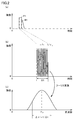
- FIG. 1 is a diagram for explaining the principle of the electron spin resonance method.
- a static magnetic field H when a static magnetic field H is applied to a substance (free radical) having unpaired electrons and exhibiting paramagnetism, the spin energy state of the unpaired electrons is split into two levels. .
- This split is also called Zeeman split.
- An energy difference ⁇ E between an electron spin ( ⁇ spin) at a high energy level of two levels and an electron spin ( ⁇ spin) at a low energy level is expressed by the following formula (1).
- g is also called “g value” and is a constant specific to each free radical.
- ⁇ is also called a “Bohr magneton” and is a constant indicating the magnetic moment of one unpaired electron.
- FIG. 1B shows that the energy difference ⁇ E due to Zeeman splitting is proportional to the static magnetic field H, as can be seen from the equation (1).
- the energy difference ⁇ E due to Zeeman splitting is proportional to the static magnetic field H, as can be seen from the equation (1).
- the Planck constant is represented by h
- the frequency of the electromagnetic wave is represented by ⁇ .
- Equation (2) a signal (resonance signal) indicating absorption of energy by free radicals is observed.
- a signal resonance signal
- various characteristics such as the state of electron spin or the density of unpaired electrons (for example, g value and hyperfine coupling constant) are obtained. Can be obtained.
- a method of changing the static magnetic field H while keeping the frequency ⁇ (in other words, energy h ⁇ ) of the electromagnetic wave constant and a method of changing the frequency ⁇ of the electromagnetic wave while keeping the static magnetic field H constant. It is done.
- the former method is realized by a continuous wave (CW) -ESR method.
- CW-ESR method a static magnetic field is swept by sweeping an exciting current of an electromagnet while a sample is irradiated with an electromagnetic wave having a constant frequency as a continuous wave.
- sweeping of a static magnetic field can be easily realized.
- a measurement apparatus including a resonator or the like generally has frequency dependency. Therefore, since the frequency dependence of the resonance signal must be corrected, the frequency sweep of the electromagnetic wave tends to be avoided.
- the pulse ESR method can be used instead of the frequency sweep of the electromagnetic wave.
- a pulsed electromagnetic wave hereinafter abbreviated as “pulse wave”
- pulse wave a pulsed electromagnetic wave
- any one of the free induction decay (FID) method and the spin echo method which are more detailed classifications of the pulse ESR method, is used.
- FIG. 2 is a diagram for explaining the FID method.
- a pulse wave P1 is applied to a sample provided in a static magnetic field.
- FIG. 2B is an enlarged view of the pulse wave P1.
- the pulse wave P1 has a single frequency ⁇ p.
- the pulse width of the pulse wave P1 is ⁇ t.
- FIG. 2 (c) shows the pulse wave P1 displayed in the time domain shown in FIG. 2 (b) in the frequency domain by Fourier transform.
- FIG. 2 (c) shows that the spectrum of the pulse wave P1 has a spread (spectrum width) ⁇ based on the uncertainty principle centering on the frequency ⁇ p. Since the spectrum width ⁇ is substantially equal to the reciprocal (1 / ⁇ t) of the pulse width ⁇ t, the spectrum width ⁇ (in other words, the frequency band) can be adjusted by controlling the pulse width ⁇ t. Thus, in the pulse ESR method, even if the pulse waves P1 and P2 have a single frequency ⁇ p, the resonance condition is established by adjusting the frequency band by appropriately setting the pulse width ⁇ t. Can do.
- the electrons transit to the high energy level, and the response signal R1 is observed immediately after the irradiation with the pulse wave P1. Due to the disturbance of the phase of the response signal R1 inside the sample, the signal intensity of the response signal R1 attenuates with time. The duration and intensity of the response signal R1 depends on the magnetic parameters of the sample.
- An ESR spectrum is acquired by performing a Fourier transform on the response signal R1.
- FIG. 3 is a diagram for explaining the spin echo method.
- pulse waves P1 and P2 are irradiated to a sample provided in a static magnetic field at a time interval ⁇ .
- a response signal R1 by FID is generated immediately after irradiation with the pulse wave P1.
- the response signal R2 is observed after time ⁇ has elapsed from the irradiation of the pulse wave P2.
- the response signal R2 has a mountain shape in which the response signal R1 and an inverted version of the response signal R1 with respect to the central axis passing through the maximum value of the response signal R1 are overlapped.
- the intensity of the response signal R2 is modulated according to the magnetic parameter of the sample.
- An ESR spectrum is acquired by Fourier transforming the response signals R1 and R2.
- the advantage of the FID method is that it can be used even when the intensity of the pulse wave P1 is relatively small.
- the FID method is useful because it is difficult to generate a high-intensity pulse in an ESR having a general high frequency (for example, a resonance frequency ⁇ in a range from several GHz to several hundred GHz as described later).
- the spin echo method has an advantage in that the response signals R1 and R2 after Fourier transform become sharp because the phase information of the signal can be determined.
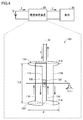
- FIG. 4 is a diagram for explaining the current measurement mechanism in the first embodiment.
- the measurement system includes a DC power supply 10, a current measurement device 20, and a load 30.
- the DC power supply 10 supplies current I to load 30.
- the DC power supply 10 is typically a stabilized power supply configured to be able to supply a highly stable DC current, but is not limited thereto, and may be, for example, a power storage device (battery or the like).
- the load 30 is not particularly limited as long as it is a device that consumes the current I supplied from the DC power supply 10.
- the current measuring device 20 is electrically connected between the DC power supply 10 and the load 30.
- Current measuring device 20 includes a measuring unit 100 for measuring current I supplied from DC power supply 10 to load 30.
- the measuring unit 100 is provided with a coil 110.
- the coil 110 is a saddle coil. That is, the coil 110 is configured such that the coil 110 as a whole has a cylindrical shape by disposing the raised portions (front bridge or rear bridge) of each of the two saddle-shaped coils on the outside. Yes.
- the coil 110 includes curved portions 112 and 114 and connecting portions 116 and 118.
- the bending portion 112 (first bending portion) and the bending portion 114 (second bending portion) are formed so as to be curved in an arc around the common axis Ax.
- Each of connecting portion 116 (first bending portion) and connecting portion 118 (second bending portion) extends along the extending direction of axis Ax, and is formed to connect bending portion 112 and bending portion 114. Is done.
- the connecting part 116 and the connecting part 118 are arranged to face each other with respect to the axis Ax.
- a static magnetic field H is generated.
- the direction of the static magnetic field H is a direction substantially perpendicular to the axis Ax.
- the resonator 120 is provided on the axis Ax between the bending portion 112 and the bending portion 114.
- a sample whose characteristics such as an ESR spectrum and magnetic parameters are unknown is used inside the resonator.
- characteristics such as magnetic parameters are obtained.
- the frequency (resonance frequency) ⁇ 0 at which electron spin resonance occurs can be obtained from the ESR spectrum.
- the excitation current flowing through the coil can be measured, if the correspondence between the excitation current and the static magnetic field is acquired in advance, the static magnetic field H 0 when electron spin resonance occurs is calculated from the excitation current. Can do. Therefore, for example, by substituting the resonance frequency ⁇ 0 and the static magnetic field H 0 into the above equation (2), the g value of the sample can be obtained.
- the inventors of the present invention are the current I flowing through the coil 110, the static magnetic field H (H 0 ) generated by the current I, and the resonance when electron spin resonance occurs when the static magnetic field H is applied. It was noted that there is a correspondence relationship with the frequency ⁇ 0 . By predefining this correspondence, the current I that is a parameter to be measured can be calculated from the static magnetic field H 0 and the resonance frequency ⁇ 0 .
- the calibration is performed in consideration of errors due to processing accuracy or misalignment of each component included in the current measuring device 20. Further, the correspondence between the current I and the static magnetic field H can be acquired in advance. Therefore, if the correspondence between the static magnetic field H 0 and the resonance frequency ⁇ 0 is acquired, the current I can be calculated from the static magnetic field H 0 and the resonance frequency ⁇ 0 .
- a standard material 122 having various known characteristics such as an ESR spectrum and a magnetic parameter (for example, a g value) is provided inside the resonator 120.
- the resonance frequency ⁇ 0 when electron spin resonance occurs can be measured. Therefore, by using the equation (2), the static magnetic field H 0 when the electron spin resonance occurs is calculated from the resonance frequency ⁇ 0 and the g value of the standard material 122. That is, by using a standard 122, it is possible to obtain the corresponding relationship between the static magnetic field H 0 and the resonance frequency [nu 0.
- the current I is calculated from the resonance frequency ⁇ 0 by preliminarily defining a correspondence relationship between the current I, the static magnetic field H (H 0 ), and the resonance frequency ⁇ 0. It becomes possible. As long as the device configuration (specifically, the configuration of the coil 110 and the positional relationship between the coil 110 and the resonator 120) is not changed, the correspondence between the current I and the static magnetic field H is fixed. Therefore, the correspondence relationship between the current I and the resonance frequency ⁇ 0 can be defined more simply.
- Figure 5 is a diagram for explaining an example of a method of calculating a current I 0 from the resonant frequency [nu 0.
- the horizontal axis represents the resonance frequency ⁇
- the vertical axis represents the current I.
- the correspondence relationship between the current I and the resonance frequency ⁇ 0 is basically a linear function passing through the origin.
- the current measurement device 20 has such a correspondence as a function or a map in advance, for example, whereby the current I 0 can be calculated from the resonance frequency ⁇ 0 .
- the magnetic resonance system to which the current measurement device 20 can be applied is not limited to the NMR measurement system, and may be an MRI measurement system, for example.
- the use of the current measurement device according to the first embodiment is not limited to the magnetic resonance measurement system as long as there is a demand for measuring current with high accuracy.
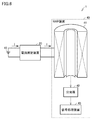
- FIG. 6 is a block diagram schematically showing the configuration of an NMR measurement system equipped with the current measurement device 20 according to the first embodiment.
- the NMR measurement system 1 includes a DC power supply 10, a current measurement device 20, and an NMR device 40.
- the NMR apparatus 40 includes an electromagnet 41 as a load 30 (see FIG. 4), a spectroscope 42, and a signal processing apparatus 43.
- DC power supply 10 supplies current I to NMR apparatus 40.
- the magnitude of the current I is, for example, in the range of 100 A or more and 500 A or less, and typically 300 A.
- the electromagnet 41 includes a superconducting coil, and generates a strong magnetic field by the current I supplied from the DC power supply 10.
- the generated strong magnetic field is applied to a sample (not shown).
- a superconducting material is used for the electromagnet 41, a slight current loss occurs, so that the strong magnetic field can be attenuated over time. Therefore, the current I is always supplied from the DC power supply 10 to the electromagnet 41 in order to suppress the attenuation of the strong magnetic field.
- the spectroscope 42 splits the light emitted from the sample and outputs a signal indicating the spectral result to the signal processing device 43.
- the signal processing device 43 acquires an NMR spectrum by performing various signal processing on the signal received from the spectroscope 42. Further, the signal processing device 43 calculates the characteristics of the sample by analyzing the NMR spectrum.
- the current measuring device 20 is connected between the DC power supply 10 and the electromagnet 41, and measures the current I supplied from the DC power supply 10 to the electromagnet 41.
- the configuration of the current measuring device 20 will be described in detail with reference to FIGS.
- FIG. 7 is a block diagram showing the configuration of the current measuring device 20 in more detail.
- current measuring device 20 includes oscillator 210, coupler 220, gate 230, amplifier 240, circulator 250, detector 260, measuring unit 100, and microcomputer 300.
- the measurement unit 100 includes the coil 110 and the resonator 120.
- the microcomputer 300 includes a control unit 310, a signal processing unit 320, and a frequency generation unit 330.
- the resonator 120, the coil 110, the oscillator 210, the detector 260, and the microcomputer 300 are provided inside the current measuring device 20 different from the NMR device 40.
- the oscillator (light source) 210 generates an electromagnetic wave having a predetermined frequency in response to a control signal from the control unit 310 and outputs it to the coupler 220.
- the coupler 220 outputs a part of the electromagnetic wave from the oscillator 210 to the gate 230, and outputs the other part of the electromagnetic wave to the detector 260 as a reference signal.
- the gate 230 and the amplifier 240 generate a pulse wave having a desired pulse width and pulse intensity (wave height). More specifically, the gate 230 passes or blocks electromagnetic waves in response to a gate signal from the control unit 310. The amplifier 240 amplifies the electromagnetic wave that has passed through the gate 230 in response to a control signal from the control unit 310.
- the circulator 250 outputs the pulse wave generated by the gate 230 and the amplifier 240 to the resonator 120.
- the circulator 250 is configured such that the pulse wave does not propagate directly from the amplifier 240 to the detector 260.
- the coil 110 generates a static magnetic field H using the current I supplied from the DC power supply 10 to the NMR apparatus 40 as an excitation current.
- a standard substance 122 (see FIG. 4) is accommodated in the resonator 120.
- a static magnetic field H is applied to the resonator 120 and a pulse wave is applied to the resonator 120 to establish a resonance condition
- a resonance signal modulated by electron spin resonance shown in FIG. 2A or FIG. 3
- Response signals R1, R2 are generated. This resonance signal is output to the detector 260 via the circulator 250.
- the detector (detector) 260 detects a resonance signal using the electromagnetic wave branched by the coupler 220 as a reference signal, and outputs a signal indicating the detection result to the signal processing unit 320.
- the microcomputer 300 includes a CPU (Central Processing Unit), a memory, an input / output buffer, and the like.
- CPU Central Processing Unit
- control unit 310 controls each component of the current measuring device 20. More specifically, control unit 310 outputs a control signal to oscillator 210, a gate signal to gate 230, and a control signal to amplifier 240 based on the frequency signal from frequency generation unit 330.
- the signal processing unit 320 converts the analog signal from the detector 260 into a digital signal. Further, the signal processing unit 320 performs various signal processing such as Fourier transform on the digital signal based on a map or program stored in the memory to obtain an ESR spectrum, and the resonance frequency is obtained from the obtained ESR spectrum. ⁇ 0 is calculated. Then, the signal processing unit 320 calculates the current I 0 from the resonance frequency ⁇ 0 using the correspondence relationship between the resonance frequency ⁇ of the standard substance 122 and the current I flowing through the coil 110 as described with reference to FIG. .
- the frequency generation unit 330 generates a frequency signal that serves as a reference for the operation of the control unit 310 and the signal processing unit 320.
- a frequency generation unit 330 having a frequency accuracy higher than that having a frequency accuracy as high as possible (for example, ⁇ 50 ppb (10 to the ninth power)). desirable.
- FIG. 8 is an external perspective view of the measurement unit 100.
- the xy plane direction represents the horizontal direction.
- the x direction and the y direction are orthogonal to each other.
- the z direction represents the vertical direction.
- the direction of gravity is downward in the z direction.
- the measuring unit 100 has, for example, a cylindrical casing 101. On the upper surface 101U of the casing 101, ports 102 to 105, a direction magnet 106, and a direction mark 107 are provided.
- the casing 101 is configured such that its lower surface 101L can be fixed to a base isolation table (not shown) or the like.
- the port 102 is an input terminal for current I from the DC power supply 10 to the measuring unit 100.
- the port 103 is an output terminal for current I from the measurement unit 100 to the NMR apparatus 40. Since the current I is a large current of about several hundred A, for example, it is desirable to provide the input terminal and the output terminal separately as described above.
- the port 104 is an input / output terminal for inputting a pulse wave from the circulator 250 to the resonator 120 (see FIG. 7) and outputting a resonance signal from the resonator 120 to the circulator 250.
- the input terminal and the output terminal can be shared, so that the structure of the measurement unit 100 can be simplified.
- the port 105 is an opening for injecting (or replenishing) a coolant 150 to be described later or for allowing the vaporized coolant 150 to escape.
- the azimuth magnet 106 points in the north direction using the action of the magnet.
- As the orientation mark 107 for example, a symbol indicating a north direction as shown in FIG. 8 can be used. By aligning the north direction indicated by the azimuth mark 107 with the north direction indicated by the azimuth magnet 106 (magnetic north), the installation direction of the measurement unit 100 with respect to geomagnetism can be determined. Details of the azimuth magnet 106 and the azimuth mark 107 will be described later.
- the configuration in which the current measuring device 20 includes the circulator 250 is described as an example, but the circulator 250 may be omitted.
- the signal transmission path must be separated into a transmission path from the amplifier 240 to the measurement unit 100 and a transmission path from the measurement unit 100 to the detector 260. That is, since it is necessary to provide two ports instead of the port 104, the structure of the measurement unit 100 can be complicated as compared with the structure shown in FIG.
- the conditions for adjusting the signal input to the resonator 120 and the signal output from the resonator 120 increase, so that the resonance signal can be easily optimized. For example, while adjusting the input coupling state (coupling) to send high-intensity pulse waves (P1, P2), the output coupling state is lowered to adjust the resonance Q value.
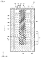
- FIG. 9 is a cross-sectional view of the measurement unit 100 along the line IX-IX shown in FIG.
- measurement unit 100 includes a sample tube 130, a heat insulating container 140, a coolant 150, and a magnetic shield 160.
- Sample tube 130 further includes holders 132 and 134 and cryopump 136 in addition to coil 110 (see curved portions 112 and 114 and coupling portions 116 and 118 in FIG. 2) and resonator 120.
- the coil 110 is made of, for example, a high temperature superconducting material.
- a known material can be used as the high-temperature superconducting material.
- a material having a superconducting transition temperature lower than the boiling point of liquid nitrogen is used.
- the resonator 120 is, for example, a helical resonator.
- DPPH is provided as a standard material 122 inside the resonator 120.
- the type of the standard substance 122 is not limited to this, and may be, for example, BDPA (1,3-bisdipheylene-2-phenylally).
- BDPA 1,3-bisdipheylene-2-phenylally
- the holder 132 holds the coil 110.
- the holder 134 holds the resonator 120, a pulse wave transmission line input from the circulator 250 via the port 104, and a resonance signal transmission line output from the resonator 120 via the port 104.
- Each of the holders 132 and 134 is formed of, for example, reinforced resin.
- the holder 132 is configured so that the holder 134 can be inserted. In a state where the holder 134 is inserted into the holder 132, the holders 132 and 134 are in close contact with each other, and only a slight space (gap) is generated between the holder 132 and the holder 134.
- the cryopump 136 is provided in the gap between the holder 132 and the holder 134. When the temperature of the cryopump 136 itself decreases, the cryopump 136 captures gas molecules inside the sample tube 130 by condensing or adsorbing them on a cryogenic surface (not shown).
- the heat insulating container 140 is configured to accommodate the sample tube 130 and to hold a coolant 150 for cooling the sample tube 130. Since the heat insulating container 140 has a vacuum heat insulating layer (not shown), heat conduction from the outside of the heat insulating container 140 to the coolant 150 is suppressed.
- the type of the coolant 150 can be selected as appropriate according to the transition temperature of the high-temperature superconducting material used for the coil 110. In Embodiment 1, liquid nitrogen is used.
- the magnetic shield 160 covers the outer wall of the casing 101 (in other words, covers the coil 110) and shields the geomagnetism.
- a material having high magnetic permeability is preferable. Examples of such a material include permalloy and permendur.
- the coil 110 is for realizing the superconducting state of the coil 110. Accordingly, it is possible to reduce a temperature change due to the generation of Joule heat in the coil 110 and to reduce noise (thermal noise) due to thermal motion of atoms or molecules constituting the coil 110. As a result, it is possible to suppress the deterioration of the measurement accuracy of the current I.
- the Q value, the resonance frequency, and the coupling constant (coupling) of the resonator 120 change.
- the waveform of the resonance signal output from can also change.
- the ESR spectrum obtained by Fourier-transforming the resonance signal can show temperature dependence. Therefore, it is desirable to keep the temperature of the resonator 120 constant.
- the cooling liquid 150 to suppress the thermal expansion or contraction of the resonator 120, it is possible to reduce the fluctuation of the measured value of the current I accompanying the change in room temperature.
- measurements can be performed under the same temperature conditions in various room temperature environments regardless of the season.
- the ratio (occupancy ratio) of ⁇ spin and ⁇ spin (see FIG. 1) among electron spins is determined by the Boltzmann distribution law. As the temperature of the standard material 122 decreases due to cooling of the resonator 120, ⁇ Spin occupancy is relatively high. That is, since the number of electron spins that can be transitioned from the energy level of ⁇ spin to the energy level of ⁇ spin increases, the intensity of the resonance signal can be increased.
- cryopump 136 In a state where the coolant 150 is not held in the heat insulating container 140 and the sample tube 130 is not cooled (not shown), the cryopump 136 allows the presence of gas molecules inside the sample tube 130. This is because when the resonator 120 is cooled using the cooling liquid 150, gas molecules are necessary as a medium for causing heat conduction from the resonator 120 to the cooling liquid 150.
- the cryopump 136 captures gas molecules and holds the inside of the sample tube 130 in a vacuum state. To do.
- Each of the ports 102 to 104 is configured to pass an electromagnetic wave while not allowing air to pass through and maintain a vacuum state.
- the resonance state changes according to the density difference between the liquid and the gas or the position of the gas, which may cause noise. Further, in a state where air is contained in the resonator 120, free radicals are generated from water molecules or oxygen molecules in the air, which may become background noise in the resonance signal. Such a factor can be eliminated by making the inside of the resonator 120 into a vacuum state using the cryopump 136.
- the wavelength of the electromagnetic wave (pulse wave) is different between the case where the inside of the resonator 120 is in a vacuum state and the case where it is not (the wavelength shortening rate is different), it may cause a measurement error of the resonance frequency ⁇ .
- the effect of water molecules is particularly great on the wavelength shortening rate.
- shock waves such as sound waves may be generated when the bubbles burst due to the boiling of the coolant 150. Since the shock wave medium is eliminated by making the inside of the sample tube 130 in a vacuum state, the shock wave is hardly transmitted. That is, the impact and vibration transmitted from the coolant 150 to the resonator 120 can be mitigated.
- the measurement unit 100 is preferably installed so that the static magnetic field H generated by the coil 110 and the geomagnetism He are substantially orthogonal. A method for installing the measurement unit 100 in this way will be described in detail below.
- the geomagnetism He exists in the plane stretched by the north direction vector (magnetic north) indicated by the compass and the vertical vector.
- the angle formed by the geomagnetism He and the horizontal direction may vary depending on the latitude of the place where the measuring unit 100 is installed.
- the angle between the geomagnetism He and the horizontal direction is, for example, about 45 ° in Okinawa and about 60 ° in Hokkaido.
- the geomagnetism He may be affected by the structural material of the building in which the measuring unit 100 is installed in the plane.
- the vertical direction is the z direction.
- the magnetic north indicated by the azimuth magnet 106 provided on the upper surface 101U of the housing 101 is assumed to be a plane direction (yz plane direction) perpendicular to the paper surface.
- yz plane direction plane direction perpendicular to the paper surface.
- the angle between the geomagnetism He and the horizontal direction can vary depending on the latitude of the installation location of the current measuring device 20, it is within the yz plane at any latitude. Therefore, if the current measuring device 20 is installed so that the static magnetic field H generated by the coil 110 is in a plane direction parallel to the paper surface (xz plane direction, ie, east or west direction), the static magnetic field H and the geomagnetism are independent of the latitude. He can be made substantially orthogonal.
- the measurement unit 100 when the user installs the measurement unit 100, the measurement unit 100 causes the direction of the static magnetic field H to be east or west by matching the direction of the direction mark 107 with the magnetic north indicated by the direction magnet 106. It is comprised so that it may become the direction of. Thereby, the orthogonal relationship as described above can be easily established. Moreover, since it is not necessary to consider the influence of the structural material of a building, the expense and time for investigating the detailed data of the geomagnetic He in the installation location of the measurement part 100 can be saved. In the north magnetic pole or the south magnetic pole, if the current measuring device 20 is installed so that the static magnetic field H by the coil 110 is in the horizontal direction, the orthogonal condition can be satisfied.
- the outer shape of the measurement unit 100 will be described (see FIG. 8). Although various shapes can be adopted as the outer shape of the measuring unit 100, it is considered most common to adopt a rectangular parallelepiped shape. However, in the case of a rectangular parallelepiped shape, the measurement unit 100 can be installed with an arbitrary surface of the rectangular parallelepiped as a bottom surface. Therefore, the static magnetic field H and the geomagnetism He may not be orthogonal to each other depending on the installation method.
- a cylindrical shape is employed as the outer shape of the measurement unit 100.
- the measurement part 100 it becomes impossible to make a cylindrical side surface into a bottom face.
- ports 102 to 105 are provided on the cylindrical upper surface 101U. Therefore, even if the user is not particularly conscious, the measuring unit 100 is installed such that the cylindrical lower surface 101L is the bottom surface.
- the orthogonal relationship between the static magnetic field H and the geomagnetism He can be reliably ensured. The effect of making the static magnetic field H and the geomagnetic He orthogonal to each other will be described later.
- the measurement unit 100 when the outer shape of the measurement unit 100 is a rectangular parallelepiped shape, the measurement unit 100 may be deformed over time due to a pressure difference between the atmospheric pressure and the pressure of the vacuum heat insulation layer of the heat insulation container 140. By making the outer shape cylindrical, such deformation can be made difficult to occur.
- the resonance frequency ⁇ of the electromagnetic wave and the static magnetic field H are in a proportional relationship. Therefore, the resonance frequency ⁇ increases as the static magnetic field H increases.
- the number of turns of the coil used in the general ESR method is several thousand or more. For this reason, the generated static magnetic field is relatively strong, often in the order of 1T (Tesla) (for example, a range from 0.1T to 10T). Therefore, from the equation (2), the resonance frequency ⁇ of the electromagnetic wave is in the range from several GHz to several hundred GHz.
- the inductance of the coil increases.
- the inductance of the coil 110 is excessively large, the static magnetic field H may hardly change even if the current I flowing through the coil 110 fluctuates. That is, there is a possibility that a minute fluctuation of the current I cannot be measured. Therefore, in order to improve the measurement accuracy of the current I, it is desirable to reduce the number of turns of the coil 110 to make the inductance of the coil 110 as small as possible. Therefore, in the first embodiment, it is preferable to use the coil 110 of about 1 to several turns, and it is more preferable to use the coil 110 of 1 to 3 turns.
- the generated static magnetic field H is also weakened.
- the electromagnetic wave resonance frequency ⁇ is, for example, about 100 MHz to 120 MHz.
- the current measurement method according to the first embodiment can be referred to as a “low frequency ESR method” in that the resonance frequency ⁇ is lower than the resonance frequency in a general ESR method.
- the correspondence relationship (function or map) between the resonance frequency ⁇ of the standard material 122 and the current I flowing through the coil 110 is obtained. It is necessary for the signal processing unit 320 to have in advance. Since DPPH is a typical material of the standard substance in the ESR method, the ESR spectrum and magnetic parameters have been examined in detail. Therefore, the correspondence can be easily and precisely defined.
- the resonance frequency ⁇ 0 can be determined with high accuracy.
- the measuring unit 100 is configured to reduce the influence of geomagnetism as much as possible. The reduction effect will be described.
- the static magnetic field H generated by the current I is, for example, about 50 G as described above.
- the geomagnetism He varies depending on the location, but the average value in Japan is about 0.46G. That is, the geomagnetism He is weaker by about two orders of magnitude than the static magnetic field H.
- the daily variation of magnetic north is very small, about 0.1 °.
- the ratio of the magnitude of the daily change of the geomagnetism He to the magnitude of the geomagnetism He is also small, and ranges from 0.1% (normal time) to 1% (when a magnetic storm occurs). Therefore, both the daily variation of magnetic north and the magnitude of the daily variation of geomagnetism He can be ignored.
- the geomagnetism He is shielded by the magnetic shield 160.
- the geomagnetism He can be further reduced by about two digits. That is, by providing the magnetic shield 160, the geomagnetism He becomes weaker by about four digits than the static magnetic field H.
- the geomagnetism He is subjected to vector addition (or vector subtraction) with respect to the static magnetic field H, so the influence of the geomagnetism He is greatest.
- the coil 110 is provided so that the static magnetic field H is substantially orthogonal to the geomagnetism He. In this case, a synthesized magnetic field is obtained by vector synthesis of the geomagnetism He and the static magnetic field H.
- the rate of increase of the synthetic magnetic field with respect to the static magnetic field H is estimated to be about the square of the ratio of the geomagnetic He to the static magnetic field H (that is, 10 to the fourth power), that is, 10 to the eighth power, and is very small.
- the measurement unit 100 as shown in FIGS. 8 and 9, the influence of the geomagnetism He can be greatly reduced.
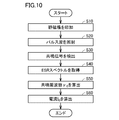
- FIG. 10 is a flowchart for explaining the current measuring method according to the first embodiment. This flowchart is called from the main routine and executed when a predetermined condition is satisfied or every elapse of a predetermined period.
- Each step of the flowchart (hereinafter abbreviated as S) is basically realized by software processing by the microcomputer 300, but is realized by hardware processing using an electronic circuit fabricated in the microcomputer 300. May be.
- the current I from the DC power source 10 is supplied to the NMR apparatus 40 via the current measuring apparatus 20.
- a static magnetic field H is generated by the current I flowing through the coil 110, and the generated static magnetic field H is applied to the resonator 120.
- the control unit 310 controls the oscillator 210, the gate 230, and the amplifier 240 to generate a pulse wave having a desired pulse width and pulse intensity.
- the generated pulse wave is supplied to the resonator 120 via the circulator 250.
- a resonance condition is established between the static magnetic field H and the frequency ⁇ of the pulse wave, electron spin resonance occurs in the resonator 120.
- the resonance signal modulated by electron spin resonance is output from the resonator 120 and sent to the detector 260 through the circulator 250.
- the signal processing unit 320 obtains a resonance signal (digital signal) by performing analog-digital conversion processing of the resonance signal (analog signal) detected by the detector 260. Further, the signal processing unit 320 obtains an ESR spectrum (absorption spectrum or dispersion spectrum) in the frequency domain by performing a Fourier transform process on the resonance signal in the time domain (S40). Then, the signal processing unit 320 calculates the resonance frequency ⁇ 0 from the ESR spectrum (S50). Since these methods are known, detailed description will not be repeated.
- the signal processing unit 320 calculates the current I 0 flowing through the coil 110 from the calculated resonance frequency ⁇ 0 using the correspondence relationship between the resonance frequency ⁇ of the standard material 122 and the current I flowing through the coil 110. . Since this calculation method has been described in detail with reference to FIG. 5, the description will not be repeated.
- the microcomputer 300 by calculating the current I 0, for example, executes the processing of S20 ⁇ S60 every predetermined period may be calculated the stability of the current I supplied from the DC power supply 10.
- Stability means the ratio of the fluctuation amount of the current I to the magnitude of the current I, and is expressed as 1 ppm (10 to the sixth power), for example.
- the measurement unit 100 calculates the stability of the current I even on the order of sub ppm (less than minus 6 to the sixth power). can do.
- a method using a branch resistor or a method using a Hall element is known. Since the branch resistance has temperature dependence, the resistance value may change due to the heat generation of the branch resistance, which may reduce the current measurement accuracy.
- the uniformity of the magnetic field applied to the Hall elements is low. Further, in order to increase the magnetic field sensitivity of the Hall element, high electron mobility is required. In this case, the temperature dependence of the magnetic field sensitivity is also increased. Further, in the Hall element, an offset voltage exists even when no magnetic field is applied, and this offset voltage may also have temperature dependence. For the reasons described above, there is a possibility that sufficient current measurement accuracy cannot be obtained even with a method using a Hall element.
- the current can be measured with higher accuracy than the method using a branch resistor or a Hall element. it can.
- the stability of the current can be measured with high accuracy, so that the magnitude of the contribution of the stability of the current can be quantitatively evaluated.
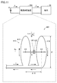
- FIG. 11 is a diagram for explaining a coil configuration according to the second embodiment.
- a coil 410 is a Helmholtz coil, and includes a coil (first circular coil) 412 shown on the left side in the drawing and a coil (second circular coil) 414 shown on the right side in the drawing. Consists of including.
- Each of the coils 412 and 414 is a circular coil having a diameter ⁇ , and is arranged so as to have a common central axis Ax. The distance between the coil 412 and the coil 414 is equal to the radius ⁇ / 2 of each of the coils 412 and 414. Since the Helmholtz coil configuration (how to wind) is simpler than the saddle coil configuration, the Helmholtz coil is easier to manufacture.
- a static magnetic field H is generated.
- the direction of the static magnetic field H is from the coil 412 to the coil 414 and is substantially perpendicular to the surfaces of the coils 412 and 414.
- a resonator 120 is provided in the vicinity of the center of a cylindrical space sandwiched between the coil 412 and the coil 414. In other words, the resonator 120 is provided at a position equidistant from the center C1 of the coil 412 and the center C2 of the coil 414. If the number of turns of the coil 410 is 1, the diameter ⁇ of the coil 410 is 10 cm, and the current I flowing through the coil 410 is 300 A, the central static magnetic field H is about 50 G.
- FIG. 12 is a cross-sectional view for explaining the configuration of the measurement unit 400 of the current measurement device according to the second embodiment.
- FIG. 12 is contrasted with FIG.
- measurement unit 400 is different from measurement unit 100 (see FIG. 9) in that a coil 410 that is a Helmholtz coil is provided instead of coil 110 that is a saddle coil.
- the resonator 120 and the coil 410 are provided in a cylindrical casing having a central axis in the x-axis direction. By fixing the coil 410 to this housing, the coil 410 can be installed so as to be in direct contact with the coolant 150. Since the material of the housing is the same as the material of the sample tube 130A, the housing is represented integrally with the sample tube 130A in the cross-sectional view shown in FIG. The central axis extending in the z-axis direction of the sample tube 130A is orthogonal to the central axis extending in the x-axis direction of the cylindrical casing of the resonator 120, and the center of the casing on the xy plane is Pass through.
- the diameter of the sample tube 130A in the vicinity of the resonator 120 is the distance from the resonator 120 of the sample tube 130A. It is thinner than the diameter (diameter at the top in the figure). While this has an advantage that the structure of the sample tube 130 is strengthened, the structure of the sample tube 130 is complicated as compared with, for example, the structure shown in FIG. Therefore, the structure of the sample tube 130 can be further simplified by making the diameter of the sample tube 130 constant. Since the other configuration of measurement unit 400 is the same as the corresponding configuration of measurement unit 100, description thereof will not be repeated.
- the configuration using the pulse ESR method has been described, but it is not essential to use pulsed light.
- the present disclosure can also be applied to a configuration that sweeps the frequency of electromagnetic waves in the CW-ESR method.
- the configuration in which the direction of the measuring unit 100 is aligned using the azimuth magnet 106 and the azimuth mark 107 has been described.
- a configuration without the azimuth magnet 106 is also possible.
- the compass magnet 106 may be one prepared by the user.
- a rotation mechanism can be provided in the coil 110 or the coil 410, and the orthogonal condition between the geomagnetism He and the static magnetic field H can be obtained from the rotation angle at which the resonance frequency is lowest.
- 1 NMR measurement system 10 DC power supply, 20, 20A current measurement device, 30 load, 40 NMR device, 41 electromagnet, 42 spectrometer, 43 signal processing device, 100, 400 measurement unit, 101 housing, 101L lower surface, 101U upper surface , 102-105 port, 106 azimuth magnet, 107 azimuth mark, 110, 410, 412, 414 coil, 112, 114 curved portion, 116, 118 connection portion, 120 resonator, 122 standard material, 130, 130A sample tube, 132 , 132A, 134, 134A holder, 136 cryopump, 140 insulation container, 150 coolant, 160 magnetic shield, 210 oscillator, 220 coupler, 230 gate, 240 amplifier, 250 circulator, 260 detector, 300 ma Black computer, 310 control unit, 320 signal processing unit, 330 a frequency generator.
Landscapes
- Physics & Mathematics (AREA)
- General Physics & Mathematics (AREA)
- Measuring Instrument Details And Bridges, And Automatic Balancing Devices (AREA)
- Magnetic Resonance Imaging Apparatus (AREA)
Abstract
電流測定装置(20)は、共振器(120)と、コイル(110)と、発振器(210)と、検波器(260)と、信号処理部(320)とを備える。共振器(120)の内部には、常磁性を示す標準物質(122)が設けられている。コイル(110)は、直流電源(10)からの電流が流れることによって静磁場を発生し、その静磁場を共振器(120)に印加可能に構成される。検波器(260)は、コイル(110)により発生した静磁場が共振器(120)に印加され、かつ、発振器(210)からの電磁波が共振器(120)に照射された場合に、標準物質(122)の電子スピン共鳴により共振器(120)から出力される共鳴信号を検出する。信号処理部(320)は、共鳴信号に基づいて算出された標準物質(122)の共鳴周波数から、標準物質(122)の共鳴周波数とコイル(110)を流れる電流との対応関係を示すマップを用いて、コイル(110)を流れる電流を算出する。
Description
本発明は、電流測定装置およびそれを備えた磁気共鳴測定システムに関する。
近年、研究開発あるいは臨床診断の分野において、磁気共鳴測定システムが広く用いられている。磁気共鳴測定システムの例としては、NMR(Nuclear Magnetic Resonance)測定システムまたはMRI(Magnetic Resonance Imaging)測定システム等が挙げられる。磁気共鳴測定システムでは、試料に印加するための強磁場を発生するために、一般に数百A(アンペア)程度の励磁電流が直流電源から電磁石へと供給される。
J. Krzystek et al, "DDPH as a Standard for High-Field EPR", Journal of Magnetic Resonance 125, 207-211(1997).
Robert Diehl et al, "The Electromagnetic Modes of a Helical Resonator", Review of Scientific Instruments 67(11), November 1996.
R. deCarvalho et al, "Buffer-gas Loaded Magnetic Traps for Atoms and Molecules: A Primer", The European Physical Journal D 7, 289-309(1999).
D.M. Ginsberg and M.J. Melchener, "Optimum Geometry of Saddle Shaped Coils for Generating a Uniform Magnetic Field", The Review of Scientific Instruments 47(1), 122-123, January 1970.
たとえば磁気共鳴測定システムにおいて、励磁電流を安定化することができれば、時間的な揺らぎが小さい直流磁場(静磁場)を発生することができる。静磁場の揺らぎが小さいほど、最終的に得られる測定結果の精度が向上し得る。つまり、励磁電流の安定度が高いほど静磁場の揺らぎが小さくなり、それによりNMRスペクトルの精度を高めたり、MRI画像の精細さを高めたりすることができる。
上記の事情は一例に過ぎず、直流電源から供給される電流を安定化するための技術に対する要望は様々な技術分野において存在する。そのような技術を実現するためには、電流を高精度に測定する技術が求められる。
本開示は上記課題を解決するためになされたものであり、その目的は、電流を高精度に測定可能な技術を提供することである。
本開示のある局面に従う電流測定装置は、直流電源から負荷へと供給される電流を測定する。電流測定装置は、共振器と、コイルと、光源と、検出器と、信号処理部とを、上記負荷とは異なる電流測定装置の内部に備える。共振器の内部には、常磁性を示す標準物質が設けられる。コイルは、直流電源からの電流が流れることによって磁場を発生し、発生した磁場を共振器に印加可能に構成される。光源は、電磁波を共振器に照射可能に構成される。検出器は、コイルにより発生した磁場が共振器に印加され、かつ、光源からの電磁波が共振器に照射された場合に、標準物質の電子スピン共鳴または電子常磁性共鳴により共振器から出力される電磁波を検出する。信号処理部は、検出器からの信号に基づいて、標準物質の共鳴周波数を算出する。信号処理部は、検出器からの信号に基づいて算出された共鳴周波数から、標準物質の共鳴周波数とコイルを流れる電流との対応関係を用いて、コイルを流れる電流を算出する。
好ましくは、コイルの巻数は、1~3である。
好ましくは、コイルは、サドルコイルであって、第1および第2の湾曲部と、第1および第2の連結部とを含む。第1および第2の湾曲部の各々は、共通の軸周りに湾曲するように形成される。第1および第2の連結部の各々は、上記軸の延在方向に沿って延び、第1の湾曲部と第2の湾曲部とを連結するように形成される。第1および第2の連結部は、上記軸に関して互いに対向するように配置される。共振器は、上記軸上に設けられる。
好ましくは、コイルは、サドルコイルであって、第1および第2の湾曲部と、第1および第2の連結部とを含む。第1および第2の湾曲部の各々は、共通の軸周りに湾曲するように形成される。第1および第2の連結部の各々は、上記軸の延在方向に沿って延び、第1の湾曲部と第2の湾曲部とを連結するように形成される。第1および第2の連結部は、上記軸に関して互いに対向するように配置される。共振器は、上記軸上に設けられる。
好ましくは、コイルは、略同一形状を有する第1および第2の円形コイルが共通の中心軸を持つように配置されたヘルムホルツコイルである。共振器は、第1および第2の円形コイルの各々の中心から等距離の位置に設けられる。
好ましくは、コイルは、共振器に印加される磁場が地磁気に対して略直交する方向になるように設けられる。
好ましくは、電流測定装置は、磁気シールドをさらに備える。磁気シールドは、コイルを覆い、地磁気を遮蔽する。
好ましくは、コイルは、高温超電導材料により形成される。電流測定装置は、コイルを冷却するための冷却液を保持可能に構成された断熱容器をさらに備える。
好ましくは、電流測定装置は、断熱容器の内部に設けられたクライオポンプをさらに備える。クライオポンプは、自身の温度が低下するに従って気体の捕捉量が増加するように構成される。
好ましくは、標準物質は、DPPH(2,2-diphenyl-1-picrylhydrazyl)である。
本開示の他の局面に従う磁気共鳴測定システムは、上記直流電源と、上記電流測定装置と、磁気共鳴装置とを備える。磁気共鳴装置は、直流電源から供給される電流を用いて、試料に印加するための磁場を発生する他のコイルを上記負荷として含む。
本開示の他の局面に従う磁気共鳴測定システムは、上記直流電源と、上記電流測定装置と、磁気共鳴装置とを備える。磁気共鳴装置は、直流電源から供給される電流を用いて、試料に印加するための磁場を発生する他のコイルを上記負荷として含む。
本開示によれば、電流を高精度に測定することができる。
以下、本開示の実施の形態について、図面を参照しながら詳細に説明する。なお、図中同一または相当部分には同一符号を付してその説明は繰り返さない。
以下に説明する実施の形態においては、電子スピン共鳴(ESR:Electron Spin Resonance)または電子常磁性共鳴(EPR:Electron Paramagnetic Resonance)を用いて直流電流の大きさが測定される。
本開示の実施の形態において、「標準物質」との用語は、ESRスペクトル(またはEPRスペクトル)と、磁気パラメータと等の各種特性が既知の物質を意味する。「標準物質」には、ある標準物質を用いて校正された他の物質を含み得る。つまり、ある標準物質の特性を基準にして他の物質の対応する特性を規定した場合には、その「他の物質」も「標準物質」に含み得る。
<電子スピン共鳴法の原理>
電子スピン共鳴および電子常磁性共鳴の原理は同等であるため、以下、電子スピン共鳴法の原理について代表的に説明する。
電子スピン共鳴および電子常磁性共鳴の原理は同等であるため、以下、電子スピン共鳴法の原理について代表的に説明する。
図1は、電子スピン共鳴法の原理を説明するための図である。図1(a)を参照して、不対電子を持ち常磁性を示す物質(フリーラジカル)に静磁場Hが印加されると、不対電子のスピンのエネルギー状態は2つの準位に分裂する。この分裂はゼーマン分裂とも称される。2つの準位のうちエネルギーの高い準位にある電子スピン(αスピン)と、エネルギーの低い準位にある電子スピン(βスピン)とのエネルギー差ΔEは、下記式(1)で表される。式(1)において、gは「g値」とも呼ばれ、各フリーラジカルに固有の定数である。βは「ボーア磁子」とも呼ばれ、1つの不対電子がもつ磁気モーメントを示す定数である。
ΔE=gβH ・・・(1)
図1(b)において、横軸は静磁場Hを表し、縦軸はエネルギーを表す。図1(b)には、式(1)から分かるように、ゼーマン分裂によるエネルギー差ΔEが静磁場Hに比例することが示されている。ここでエネルギー差ΔEに等しいエネルギーを有する電磁波がフリーラジカルに照射されると、βスピンをもつ電子は、電磁波を吸収してαスピンのエネルギー準位へと遷移する。すなわち、下記式(2)に示すように、電磁波のエネルギーがエネルギー差ΔEに等しい場合に電磁波の吸収による共鳴現象が起こる。式(2)において、プランク定数をhで表し、電磁波の周波数をνで表す。
図1(b)において、横軸は静磁場Hを表し、縦軸はエネルギーを表す。図1(b)には、式(1)から分かるように、ゼーマン分裂によるエネルギー差ΔEが静磁場Hに比例することが示されている。ここでエネルギー差ΔEに等しいエネルギーを有する電磁波がフリーラジカルに照射されると、βスピンをもつ電子は、電磁波を吸収してαスピンのエネルギー準位へと遷移する。すなわち、下記式(2)に示すように、電磁波のエネルギーがエネルギー差ΔEに等しい場合に電磁波の吸収による共鳴現象が起こる。式(2)において、プランク定数をhで表し、電磁波の周波数をνで表す。
hν=gβH ・・・(2)
電子スピン共鳴法では、式(2)に示す共鳴条件が成立すると、フリーラジカルによるエネルギーの吸収を示す信号(共鳴信号)が観測される。この共鳴信号からESRスペクトルを取得し、さらに取得されたESRスペクトルを解析することによって、そのフリーラジカルについて、電子スピンの状態あるいは不対電子の密度等の各種特性(たとえばg値および超微細結合定数に代表される磁気パラメータ)を求めることができる。
電子スピン共鳴法では、式(2)に示す共鳴条件が成立すると、フリーラジカルによるエネルギーの吸収を示す信号(共鳴信号)が観測される。この共鳴信号からESRスペクトルを取得し、さらに取得されたESRスペクトルを解析することによって、そのフリーラジカルについて、電子スピンの状態あるいは不対電子の密度等の各種特性(たとえばg値および超微細結合定数に代表される磁気パラメータ)を求めることができる。
共鳴条件を成立させるためには、電磁波の周波数ν(言い換えるとエネルギーhν)を一定にしつつ静磁場Hを変化させる手法と、静磁場Hを一定にしつつ電磁波の周波数νを変化させる手法とが考えられる。前者の手法は、連続波(CW:Continuous Wave)-ESR法により実現される。CW-ESR法では一般に、一定の周波数を有する電磁波が連続波として試料に照射された状態において、電磁石の励磁電流を掃引することによって静磁場を掃引する。
前者の手法に関し、静磁場の掃引は容易に実現可能である。これに対し、後者の手法に関し、一般に、共振器等を含む測定装置は周波数依存性を有する。よって、共鳴信号の周波数依存性を補正しなければならないため、電磁波の周波数掃引は敬遠される傾向にある。
そこで、電磁波の周波数掃引に代えて、パルスESR法を用いることができる。パルスESR法では、一定の静磁場が試料に印加された状態において、パルス状の電磁波(以下「パルス波」と略す)が試料に照射される。実施の形態1では、パルスESR法のより詳細な区分である、自由誘導減衰(FID:Free Induction Decay)法およびスピンエコー法のいずれかが用いられる。
図2は、FID法を説明するための図である。図2(a)を参照して、FID法では、パルス波P1が静磁場中に設けられた試料に照射される。図2(b)は、パルス波P1を拡大表示したものである。図2(b)に示すように、パルス波P1は単一の周波数νpを有する。パルス波P1のパルス幅はΔtである。
図2(c)は、図2(b)に時間領域表示されたパルス波P1をフーリエ変換することによって周波数領域にて表示したものである。図2(c)には、パルス波P1のスペクトルが、周波数νpを中心として、不確定性原理による拡がり(スペクトル幅)Δνを持つことが示されている。スペクトル幅Δνはパルス幅Δtの逆数(1/Δt)にほぼ等しいので、パルス幅Δtを制御することによってスペクトル幅Δν(言い換えれば周波数帯域)を調整することができる。このように、パルスESR法では、パルス波P1,P2が単一の周波数νpを有するものであっても、パルス幅Δtを適切に設定することにより周波数帯域を調整して共鳴条件を成立させることができる。
共鳴条件が成立している場合、電子は高エネルギー準位へと遷移し、パルス波P1の照射直後から応答信号R1が観測される。試料内部での応答信号R1の位相の乱れにより、応答信号R1の信号強度は時間とともに減衰する。応答信号R1の継続時間および強度は、試料の磁気パラメータに依存する。応答信号R1をフーリエ変換することにより、ESRスペクトルが取得される。
図3は、スピンエコー法を説明するための図である。図3を参照して、パルスESR法では、パルス波P1,P2が静磁場中に設けられた試料に時間間隔τで照射される。共鳴条件が成立している場合、スピンエコー法においても、パルス波P1の照射直後にFIDによる応答信号R1が生じる。さらに、スピンエコー法では、パルス波P2の照射から時間τ経過後に応答信号R2が観測される。応答信号R2は、応答信号R1と、応答信号R1の最大値を通る中心軸について応答信号R1を反転させたものとを重ね合わせたような山型形状を有する。応答信号R2の強度は、試料の磁気パラメータに応じて変調する。応答信号R1,R2をフーリエ変換することにより、ESRスペクトルが取得される。
FID法の利点は、パルス波P1の強度が比較的小さい場合にも使用可能な点にある。特に、一般的な高周波(たとえば、後述するように共鳴周波数νが数GHzから数百GHzまでの範囲)のESRでは強度の大きいパルスを生成することが難しいため、FID法は有用である。一方、スピンエコー法は、信号の位相情報を確定できるため、フーリエ変換後の応答信号R1,R2がシャープになる点に利点を有する。
[実施の形態1]
<電流測定メカニズム>
実施の形態1に係る電流測定装置においては、以上で説明したパルスESR法を用いて電流測定が行なわれる。
<電流測定メカニズム>
実施の形態1に係る電流測定装置においては、以上で説明したパルスESR法を用いて電流測定が行なわれる。
図4は、実施の形態1における電流測定メカニズムを説明するための図である。図4を参照して、測定システムは、直流電源10と、電流測定装置20と、負荷30とを備える。
直流電源10は、電流Iを負荷30に供給する。直流電源10は、典型的には安定度の高い直流電流を供給可能に構成された安定化電源であるが、これに限定されるものではなく、たとえば蓄電装置(バッテリ等)であってもよい。負荷30は、直流電源10から供給された電流Iを消費する機器であれば特に限定されない。
電流測定装置20は、直流電源10と負荷30との間に電気的に接続される。電流測定装置20は、直流電源10から負荷30へと供給される電流Iを測定するための測定部100を含む。測定部100にはコイル110が設けられている。
実施の形態1において、コイル110はサドルコイルである。すなわち、コイル110は、2つのサドル(鞍)形状のコイルの各々の盛り上がった部分(前橋または後橋)を互いに外側に配置することで、コイル110全体としては円筒形状になるように構成されている。
より具体的には、コイル110は、湾曲部112,114と、連結部116,118とを含む。湾曲部112(第1の湾曲部)と湾曲部114(第2の湾曲部)とは、各々が共通の軸Axの周りに円弧状に湾曲するように形成される。連結部116(第1の湾曲部)および連結部118(第2の湾曲部)の各々は、軸Axの延在方向に沿って延び、湾曲部112と湾曲部114とを連結するように形成される。連結部116と連結部118とは、軸Axに関して互いに対向するように配置される。
電流Iが励磁電流としてコイル110を流れると、静磁場Hが発生する。静磁場Hの方向は、軸Axに略垂直な方向である。共振器120は、湾曲部112と湾曲部114との間において、軸Ax上に設けられる。
一般的なESR法において、共振器の内部には、ESRスペクトルおよび磁気パラメータ等の特性が未知の試料が用いられる。その試料について、ESRスペクトルを取得し、取得されたESRスペクトルを解析することによって、磁気パラメータ等の特性が求められる。
一例として、電子スピン共鳴が起こる周波数(共鳴周波数)ν0をESRスペクトルから求めることができる。一方、コイルを流れる励磁電流は測定可能であるため、励磁電流と静磁場との対応関係を予め取得しておけば、励磁電流から、電子スピン共鳴が起こるときの静磁場H0を算出することができる。よって、たとえば共鳴周波数ν0および静磁場H0を上記式(2)に代入することにより、その試料のg値を求めることができる。
ここで、本発明者らは、コイル110を流れる電流Iと、その電流Iにより発生する静磁場H(H0)と、その静磁場Hが印加されることにより電子スピン共鳴が起こる際の共鳴周波数ν0との間に対応関係が存在する点に着目した。この対応関係を予め規定しておくことにより、静磁場H0および共鳴周波数ν0から、測定対象のパラメータである電流Iを算出することができる。
より詳細に説明すると、電流Iと静磁場Hとの対応関係は高精度に計算可能であるので、電流測定装置20に含まれる各構成要素の加工精度または位置ずれ等による誤差を考慮して校正をさらに行なうことで、電流Iと静磁場Hとの対応関係を予め取得しておくことができる。そのため、静磁場H0と共鳴周波数ν0との対応関係を取得すれば、静磁場H0および共鳴周波数ν0から電流Iを算出することが可能になる。
そこで、実施の形態1において、共振器120の内部には、ESRスペクトルおよび磁気パラメータ(たとえばg値)等の各種特性が既知の標準物質122が設けられる。電子スピン共鳴が起こるときの共鳴周波数ν0は測定可能である。したがって、式(2)を用いることにより、共鳴周波数ν0と標準物質122のg値とから、電子スピン共鳴が起こるときの静磁場H0が算出される。すなわち、標準物質122を用いることにより、静磁場H0と共鳴周波数ν0との対応関係を取得することができる。
このように標準物質122を用いると、電流Iと、静磁場H(H0)と、共鳴周波数ν0との間の対応関係を予め規定することによって、共鳴周波数ν0から電流Iを算出することが可能になる。なお、装置構成(具体的にはコイル110の構成、およびコイル110と共振器120との位置関係)が変更されない限り、電流Iと静磁場Hとの対応関係は固定される。よって、より簡略的に、電流Iと共鳴周波数ν0との対応関係を規定することができる。
図5は、共鳴周波数ν0から電流I0を算出する手法の一例を説明するための図である。図5において、横軸は共鳴周波数νを表し、縦軸は電流Iを表す。図5の直線Lに示されるように、電流Iと共鳴周波数ν0との対応関係は、基本的には原点を通る1次関数である。このような対応関係を、たとえば関数またはマップとして電流測定装置20が予め有することによって、共鳴周波数ν0から電流I0を算出することができる。
<システム構成>
以下では、実施の形態1に係る電流測定装置20がNMR測定システムに適用される構成を例に説明する。ただし、電流測定装置20が適用可能な磁気共鳴システムはNMR測定システムに限定されず、たとえばMRI測定システムであってもよい。また、実施の形態1に係る電流測定装置の用途は、電流を高精度に測定する要望が存在するものであれば磁気共鳴測定システムに限定されない。
以下では、実施の形態1に係る電流測定装置20がNMR測定システムに適用される構成を例に説明する。ただし、電流測定装置20が適用可能な磁気共鳴システムはNMR測定システムに限定されず、たとえばMRI測定システムであってもよい。また、実施の形態1に係る電流測定装置の用途は、電流を高精度に測定する要望が存在するものであれば磁気共鳴測定システムに限定されない。
図6は、実施の形態1に係る電流測定装置20を搭載したNMR測定システムの構成を概略的に示すブロック図である。図6を参照して、NMR測定システム1は、直流電源10と、電流測定装置20と、NMR装置40とを備える。NMR装置40は、負荷30(図4参照)としての電磁石41と、分光器42と、信号処理装置43とを含む。
直流電源10は、電流IをNMR装置40に供給する。電流Iの大きさは、たとえば100A以上かつ500A以下の範囲であり、典型的には300Aである。
電磁石41は、超電導コイルを含んで構成され、直流電源10から供給された電流Iにより強磁場を発生する。発生した強磁場は図示しない試料に印加される。電磁石41には超伝導材料が用いられているものの、わずかな電流損失が生じるため、強磁場は時間の経過とともに減衰し得る。よって、強磁場の減衰を抑制するために、直流電源10から電磁石41へと電流Iが常に供給される。
分光器42は、試料から発せられた光を分光し、その分光結果を示す信号を信号処理装置43に出力する。信号処理装置43は、分光器42から受けた信号に対して各種信号処理を行なうことにより、NMRスペクトルを取得する。さらに、信号処理装置43は、NMRスペクトルを解析することにより、試料の特性を算出する。
電流測定装置20は、直流電源10と電磁石41との間に接続され、直流電源10から電磁石41に供給される電流Iを測定する。電流測定装置20の構成について、図7~図9を用いて詳細に説明する。
図7は、電流測定装置20の構成をより詳細に示すブロック図である。図6および図7を参照して、電流測定装置20は、発振器210と、結合器220と、ゲート230と、増幅器240と、サーキュレータ250と、検波器260と、測定部100と、マイクロコンピュータ300とを備える。測定部100は、図4にて説明したように、コイル110と、共振器120とを含む。マイクロコンピュータ300は、制御部310と、信号処理部320と、周波数発生部330とを含む。図7に示すように、共振器120と、コイル110と、発振器210と、検波器260と、マイクロコンピュータ300とは、NMR装置40とは異なる電流測定装置20の内部に設けられる。
発振器(光源)210は、制御部310からの制御信号に応答して、所定の周波数の電磁波を発生し結合器220へと出力する。結合器220は、発振器210からの電磁波の一部をゲート230に出力する一方で、電磁波の他の一部を参照信号として検波器260に出力する。
ゲート230および増幅器240は、所望のパルス幅およびパルス強度(波高)を持つパルス波を生成する。より具体的には、ゲート230は、制御部310からのゲート信号に応答して、電磁波を通過させたり遮断したりする。増幅器240は、制御部310からの制御信号に応答して、ゲート230を通過した電磁波を増幅する。
サーキュレータ250は、ゲート230および増幅器240により生成されたパルス波を共振器120に出力する。なお、サーキュレータ250は、パルス波が増幅器240から検波器260へと直接的には伝搬しないように構成される。
図4にて説明したように、コイル110は、直流電源10からNMR装置40へと供給される電流Iを励磁電流として静磁場Hを発生する。また、共振器120内部には標準物質122(図4参照)が収容される。静磁場Hが共振器120に印加され、かつパルス波が共振器120に照射されて共鳴条件が成立した場合、電子スピン共鳴による変調を受けた共鳴信号(図2(a)または図3に示す応答信号R1,R2)が生じる。この共鳴信号は、サーキュレータ250を介して検波器260へと出力される。
検波器(検出器)260は、結合器220によって分岐された電磁波を参照信号として共鳴信号を検波し、その検波結果を示す信号を信号処理部320に出力する。
マイクロコンピュータ300は、いずれも図示しないが、CPU(Central Processing Unit)と、メモリと、入出力バッファ等とを含んで構成される。
制御部310は、電流測定装置20の各構成要素を制御する。より具体的には、制御部310は、周波数発生部330からの周波数信号に基づいて、発振器210への制御信号、ゲート230へのゲート信号、および増幅器240への制御信号を出力する。
信号処理部320は、検波器260からのアナログ信号をデジタル信号に変換する。また、信号処理部320は、メモリに格納されたマップまたはプログラムに基づいて、上記デジタル信号に対してフーリエ変換などの各種信号処理を行なってESRスペクトルを取得し、取得されたESRスペクトルから共鳴周波数ν0を算出する。そして、信号処理部320は、図5にて説明したように、標準物質122の共鳴周波数νとコイル110を流れる電流Iとの対応関係を用いて、共鳴周波数ν0から電流I0を算出する。
周波数発生部330は、制御部310および信号処理部320の動作の基準となる周波数信号を発生する。制御部310および信号処理部320の動作精度が高くなるように、周波数発生部330としては、周波数精度ができるだけ高いもの(たとえば±50ppb(10のマイナス9乗))よりも高いものを用いることが望ましい。
<測定部の構成>
図8は、測定部100の外観斜視図である。図7および図8を参照して、xy平面方向は水平方向を表す。x方向とy方向とは互いに直交する。z方向は鉛直方向を表す。重力の向きはz方向下方である。
図8は、測定部100の外観斜視図である。図7および図8を参照して、xy平面方向は水平方向を表す。x方向とy方向とは互いに直交する。z方向は鉛直方向を表す。重力の向きはz方向下方である。
測定部100は、たとえば円筒形の筐体101を有する。筐体101の上面101Uには、ポート102~105と、方位磁石106と、方位マーク107とが設けられている。筐体101は、その下面101Lを免震台(図示せず)等に固定可能に構成される。
ポート102は、直流電源10から測定部100への電流Iの入力端子である。ポート103は、測定部100からNMR装置40への電流Iの出力端子である。電流Iは、たとえば数百A程度の大電流であるため、上記のように入力端子と出力端子とを別々に設けることが望ましい。
ポート104は、サーキュレータ250から共振器120(いずれも図7参照)へのパルス波の入力、および、共振器120からサーキュレータ250への共鳴信号の出力を行なうための入出力端子である。サーキュレータ250を設けることにより、入力端子と出力端子とを共通化できるので、測定部100の構造をシンプルにすることができる。
ポート105は、後述する冷却液150を注入(または補充)したり、気化した冷却液150を逃がしたりするための開口である。
方位磁石106は、磁石の作用を用いて北の方角を指し示す。方位マーク107としては、たとえば図8に示すような北の方角を示す記号が用いることができる。方位磁石106が指し示す北の方角(磁北)に、方位マーク107が示す北の方角を一致させることで、地磁気に対する測定部100の設置方向を決めることができる。方位磁石106および方位マーク107の詳細については後述する。
なお、図7では、電流測定装置20がサーキュレータ250を備える構成を例に説明したが、サーキュレータ250は省略してもよい。この場合には、信号の伝達経路を、増幅器240から測定部100への伝達経路と、測定部100から検波器260への伝達経路とに分離しなければならない。つまり、ポート104に代えて2つのポートを設けることが必要になるので、図8に示す構造と比べて、測定部100の構造が複雑化し得る。その一方で、共振器120への信号の入力および共振器120からの信号の出力を調整するための条件が増えるので、共鳴信号の最適化を行ないやすくなる。たとえば、入力の結合状態(カップリング)を高めて強度の高いパルス波(P1,P2)を送る一方で、出力の結合状態は低くして共鳴のQ値を上げるなどの調整が可能になる。
図9は、図8に示すIX-IX線に沿う測定部100の断面図である。図7~図9を参照して、測定部100は、試料管130と、断熱容器140と、冷却液150と、磁気シールド160とを備える。試料管130は、コイル110(図2の湾曲部112,114および連結部116,118参照)ならびに共振器120に加えて、ホルダ132,134と、クライオポンプ136とをさらに含む。
コイル110は、たとえば高温超電導材料により形成される。高温超電導材料としては公知の材料を用いることができる。実施の形態1では、超電導の転移温度が液体窒素の沸点よりも低い材料が用いられる。
共振器120は、たとえばヘリカルレゾネータである。共振器120の内部には、DPPHが標準物質122として設けられる。ただし、標準物質122の種類はこれに限定されるものではなく、たとえばBDPA(1,3-bisdipheylene-2-phenylally)であってもよい。このように標準物質122としては、DPPHまたはBDPAのような安定なフリーラジカルを用いることが好ましい。フリーラジカルの共鳴線の線幅は多くの物質の共鳴線の線幅よりも狭いので、図5にて説明したような対応関係を高精度に取得可能であるためである。
ホルダ132はコイル110を保持する。ホルダ134は、共振器120と、サーキュレータ250からポート104を介して入力されるパルス波の伝送線路と、共振器120からポート104を介して出力される共鳴信号の伝送線路とを保持する。ホルダ132,134の各々は、たとえば強化樹脂により形成される。ホルダ132は、ホルダ134を挿入可能に構成される。ホルダ134がホルダ132に挿入された状態では、ホルダ132,134は互いに密着し、ホルダ132とホルダ134との間にはわずかな空間(隙間)しか生じない。
クライオポンプ136は、ホルダ132とホルダ134との間の隙間に設けられる。クライオポンプ136は、クライオポンプ136自身の温度が低下すると、試料管130内部の気体分子を極低温面(図示せず)に凝縮または吸着させることによって捕捉する。
断熱容器140は、試料管130を収容するとともに、試料管130を冷却するための冷却液150を保持可能に構成される。断熱容器140は真空断熱層(図示せず)を有するため、断熱容器140外部から冷却液150への熱伝導が抑制される。冷却液150の種類としては、コイル110に用いられる高温超電導材料の転移温度に応じて適宜選択することができるが、実施の形態1では液体窒素が用いられる。
磁気シールド160は、筐体101の外壁を覆い(言い換えればコイル110を覆い)、地磁気を遮蔽する。磁気シールド160の材料としては透磁率の高い材料が好ましい。そのような材料としては、パーマロイまたはパーメンジュール等が挙げられる。
以上のような構成を有する測定部100において、電流Iの測定精度を向上させるための各構成要素の役割について、より詳細に説明する。
<試料管の冷却>
まず、冷却液150を用いて試料管130を冷却する理由について説明する。その理由としては主に以下の3点が挙げられる。
まず、冷却液150を用いて試料管130を冷却する理由について説明する。その理由としては主に以下の3点が挙げられる。
第1に、コイル110の超電導状態を実現するためである。これにより、コイル110におけるジュール熱の発生による温度変化を低減するとともに、コイル110を構成する原子または分子の熱運動に伴うノイズ(熱雑音)を低減することができる。その結果、電流Iの測定精度の悪化を抑制することができる。
第2に、共振器120の温度変化に伴い共振器120の熱膨張または熱収縮が起こると、共振器120のQ値、共鳴周波数、および結合定数(カップリング)が変化するため、共振器120から出力される共鳴信号の波形も変化し得る。その結果、その共鳴信号をフーリエ変換することによって取得されるESRスペクトルが温度依存性を示すようになり得る。よって、共振器120の温度を一定に維持することが望ましい。一般に、液体窒素等の冷却液を用いて装置温度を極低温の一定値に維持することは、技術的に確立されており、装置温度を室温付近にて一定値に維持するよりもやさしい。したがって、実施の形態1では冷却液150を用いて共振器120の熱膨張または熱収縮を抑制することにより、室温変化に伴う電流Iの測定値の変動を低減することができる。また、様々な室温環境下において、季節にかかわらず同一温度条件で測定を行なうことができる。
第3に、電子スピンのうちαスピンとβスピン(図1参照)との比率(占有率)はボルツマン分布則により定まるところ、共振器120の冷却により標準物質122の温度が低くなるに従って、βスピンの占有率が相対的に高くなる。つまり、βスピンのエネルギー準位からαスピンのエネルギー準位へと遷移可能な電子スピン数が大きくなるので、共鳴信号の強度を大きくすることができる。
<クライオポンプによる真空生成>
次に、クライオポンプ136の機能について、より詳細に説明する。断熱容器140に冷却液150が保持されておらず試料管130が冷却されていない状態(図示せず)では、クライオポンプ136は、試料管130内部における気体分子の存在を許容する。これは、冷却液150を用いて共振器120を冷却する際に、共振器120から冷却液150への熱伝導を生じさせるための媒質として気体分子が必要であるためである。一方で、断熱容器140に冷却液150が保持され試料管130(およびクライオポンプ136自身)が冷却された状態では、クライオポンプ136は、気体分子を捕捉し、試料管130内部を真空状態に保持する。
次に、クライオポンプ136の機能について、より詳細に説明する。断熱容器140に冷却液150が保持されておらず試料管130が冷却されていない状態(図示せず)では、クライオポンプ136は、試料管130内部における気体分子の存在を許容する。これは、冷却液150を用いて共振器120を冷却する際に、共振器120から冷却液150への熱伝導を生じさせるための媒質として気体分子が必要であるためである。一方で、断熱容器140に冷却液150が保持され試料管130(およびクライオポンプ136自身)が冷却された状態では、クライオポンプ136は、気体分子を捕捉し、試料管130内部を真空状態に保持する。
なお、上述のように、ホルダ134がホルダ132に挿入された状態において、ホルダ132とホルダ134との間にはわずかな隙間しか生じない。このような構造は、クライオポンプ136によって生成された真空状態を維持するのに寄与する。また、ポート102~104の各々は、電磁波を通過させる一方で、空気の通過は許容せず真空状態を維持するように構成されている。
共振器120内部に冷却液150が存在する場合、液体と気体との密度差あるいは気体の位置に応じて共鳴状態が変化し、ノイズの要因となり得る。また、共振器120内部に空気が含まれた状態では、空気中の水分子または酸素分子からフリーラジカルが生じ、共鳴信号におけるバックグランドノイズとなり得る。クライオポンプ136を用いて共振器120内部を真空状態にすることにより、このような要因を排除することができる。
さらに、共振器120内部が真空状態の場合とそうでない場合とでは電磁波(パルス波)の波長が異なる(波長短縮率が異なる)ので、共振周波数νの測定誤差の要因となり得る。波長短縮率に関しては特に水分子の影響が大きい。共振器120内部を真空状態にすることによって、波長短縮率に起因する誤差を抑制することができる。
また、冷却液150の沸騰による気泡が破裂する際に音波などの衝撃波が生じ得る。試料管130内部を真空状態にすることにより衝撃波の媒質がなくなるので、衝撃波が伝わりにくくなる。つまり、冷却液150から共振器120へと伝わる衝撃および振動を緩和することができる。
<測定部の方角>
測定部100は、コイル110により発生する静磁場Hと地磁気Heとが略直交するように設置することが好ましい。このように測定部100を設置するための手法について、以下に詳細に説明する。
測定部100は、コイル110により発生する静磁場Hと地磁気Heとが略直交するように設置することが好ましい。このように測定部100を設置するための手法について、以下に詳細に説明する。
北磁極および南磁極を除く地球上のあらゆる場所において、地磁気Heは、方位磁石によって示される北の方角(磁北)のベクトルと、鉛直方向のベクトルとで張られる平面内に存在する。この平面内において、地磁気Heが水平方向となす角は、測定部100の設置箇所の緯度によって異なり得る。地磁気Heが水平方向となす角は、たとえば沖縄では約45°であり、北海道では約60°である。さらに、地磁気Heは、上記平面内において、測定部100が設置された建物の構造材の影響を受ける可能性がある。
図9において、鉛直方向はz方向である。筐体101の上面101Uに設けられた方位磁石106によって示される磁北は、紙面に垂直な平面方向(yz平面方向)であるとする。地磁気Heが水平方向となす角は、電流測定装置20の設置箇所の緯度によって異なり得るものの、いずれの緯度においてもyz平面内である。よって、コイル110により発生する静磁場Hが紙面に平行な平面方向(xz平面方向、すなわち東または西方向)となるように電流測定装置20を設置すれば、緯度によらず静磁場Hと地磁気Heとを略直交させることができる。
実施の形態1では、測定部100は、ユーザが測定部100を設置する際に、方位磁石106によって示される磁北に方位マーク107の方角を一致させることで、静磁場Hの方向が東または西の方角となるように構成されている。これにより、上記のような直交関係を容易に成立させることができる。また、建物の構造材の影響を考慮しなくてもよいので、測定部100の設置箇所における地磁気Heの詳細なデータを調査するための費用および時間を節約することができる。なお、北磁極または南磁極では、コイル110による静磁場Hが水平方向になるように電流測定装置20を設置すれば、直交条件を成立させることができる。
<測定部の外形形状>
測定部100の外形形状について説明する(図8参照)。測定部100の外形形状にとしては様々な形状を採用することができるが、直方体形状を採用することが最も一般的と考えられる。しかしながら、直方体形状の場合、直方体の任意の面を底面として測定部100を設置することが可能であるため、設置の仕方によっては静磁場Hと地磁気Heとが互いに直交しない可能性がある。
測定部100の外形形状について説明する(図8参照)。測定部100の外形形状にとしては様々な形状を採用することができるが、直方体形状を採用することが最も一般的と考えられる。しかしながら、直方体形状の場合、直方体の任意の面を底面として測定部100を設置することが可能であるため、設置の仕方によっては静磁場Hと地磁気Heとが互いに直交しない可能性がある。
実施の形態1においては、図8にて説明したように、測定部100の外形形状として円筒形が採用される。これにより、測定部100を設置する際に、円筒形の側面を底面とすることはできなくなる。また、円筒形の上面101Uにはポート102~105が設けられている。したがって、ユーザが特に意識しなくとも、測定部100は円筒形の下面101Lが底面となるように設置されることになる。その結果、静磁場Hと地磁気Heとの直交関係を確実に確保することができる。なお、静磁場Hと地磁気Heとを互いに直交させることによる効果については後述する。
また、測定部100の外形形状が直方体形状の場合、大気圧と断熱容器140の真空断熱層の圧力との圧力差によって、時間の経過に伴い測定部100が変形し得る。外形形状を円筒形にすることにより、そのような変形を生じにくくすることができる。
<コイル構成>
次に、コイル110の巻数について説明する。上記式(2)に示す共鳴条件が成立する場合、電磁波の共鳴周波数νと静磁場Hとは比例関係にあるため、静磁場Hが強くなるに従って共鳴周波数νも高くなる。一般的なESR法において用いられるコイルの巻数は、数千以上である。そのため、発生する静磁場も比較的強く、1T(テスラ)程度(たとえば0.1Tから10Tまでの範囲)であることが多い。したがって、式(2)より、電磁波の共鳴周波数νは、数GHzから数百GHzまでの範囲である。
次に、コイル110の巻数について説明する。上記式(2)に示す共鳴条件が成立する場合、電磁波の共鳴周波数νと静磁場Hとは比例関係にあるため、静磁場Hが強くなるに従って共鳴周波数νも高くなる。一般的なESR法において用いられるコイルの巻数は、数千以上である。そのため、発生する静磁場も比較的強く、1T(テスラ)程度(たとえば0.1Tから10Tまでの範囲)であることが多い。したがって、式(2)より、電磁波の共鳴周波数νは、数GHzから数百GHzまでの範囲である。
コイルの巻数が大きくなるにつれて、コイルのインダクタンスは大きくなる。実施の形態1において、コイル110のインダクタンスが過度に大きいと、コイル110を流れる電流Iが変動したとしても、静磁場Hがほとんど変化しない可能性がある。つまり、電流Iの微小な変動を測定することができなくなる可能性がある。したがって、電流Iの測定精度を向上させるためには、コイル110の巻数を小さくしてコイル110のインダクタンスをできるだけ小さくすることが望ましい。よって、実施の形態1では、1巻きから数巻き程度のコイル110を用いることが好ましく、1巻きから3巻きのコイル110を用いることがより好ましい。
このように、実施の形態1では、コイル110の巻数が一般的なESR法におけるコイルの巻数よりも少ないので、発生する静磁場Hも弱くなる。一例として、コイル110の巻数が1であり、かつ、コイル110の直径φが10cmであり、かつ、コイル110を流れる電流Iが300Aである場合、静磁場Hは約40G(ガウス)である(1T=10,000G)。すなわち、実施の形態1における静磁場Hは、一般的なESR法における静磁場と比べて2桁~3桁程度も弱い。そのため、電磁波の共鳴周波数νも低くなり、たとえば数十MHzから数百MHzまでの範囲となることが多い。たとえば、静磁場Hが約50Gであり、かつ標準物質122としてDPPHを用いる場合には、電磁波の共鳴周波数νは、たとえば100MHz~120MHz程度になる。以上のように、実施の形態1に係る電流測定方法は、共鳴周波数νが一般的なESR法における共鳴周波数よりも低い点において、「低周波ESR法」と呼ぶことができる。
<標準物質の選択>
続いて、標準物質122としてDPPHを用いることが好ましい理由について説明する。その理由としては主に以下の2点が挙げられる。
続いて、標準物質122としてDPPHを用いることが好ましい理由について説明する。その理由としては主に以下の2点が挙げられる。
第1に、実施の形態1に係る電流測定装置20においては、図5にて説明したように、標準物質122の共鳴周波数νとコイル110を流れる電流Iとの対応関係(関数またはマップ)を信号処理部320が予め有していることが必要である。DPPHは、ESR法における標準物質の代表的な材料であるため、ESRスペクトルおよび磁気パラメータが詳細に調べられている。よって、上記対応関係を容易かつ精密に規定することができる。
第2に、DPPHのg因子には異方性がないので共鳴線が1つであり、さらに、その共鳴線がシャープであるためである。つまり、DPPHを用いることで、共鳴周波数ν0を高精度に決定することができる。
<地磁気の影響の低減>
電流Iを高精度に測定するためには、共振器120に印加される磁場が、コイル110を流れる電流Iにより発生する静磁場Hのみであることが望ましい。したがって、測定部100は、地磁気の影響ができるだけ低減されるように構成される。その低減効果について説明する。
電流Iを高精度に測定するためには、共振器120に印加される磁場が、コイル110を流れる電流Iにより発生する静磁場Hのみであることが望ましい。したがって、測定部100は、地磁気の影響ができるだけ低減されるように構成される。その低減効果について説明する。
実施の形態1において電流Iにより発生する静磁場Hは、上述のように、たとえば約50Gである。地磁気Heは場所によって異なるが、日本における平均値は約0.46Gとされる。つまり、地磁気Heは、静磁場Hよりも2桁程度弱い。なお、磁北の日変化は非常に小さく、約0.1°である。また、地磁気Heの大きさに対する地磁気Heの日変化の大きさの比率も小さく、0.1%(通常時)から1%(磁気嵐発生時)までの範囲である。したがって、磁北の日変化、および地磁気Heの日変化の大きさのいずれも無視することができる。
さらに、測定部100では、磁気シールド160により地磁気Heが遮蔽される。磁気シールド160の材料としてパーマロイを用いると、地磁気Heを2桁程度さらに低減することができる。つまり、磁気シールド160を設けることにより、地磁気Heは、静磁場Hよりも4桁程度弱くなる。
仮に、静磁場Hが地磁気Heに対して水平である場合、地磁気Heが静磁場Hに対してベクトル加算(またはベクトル減算)されるため、地磁気Heの影響は最も大きくなる。これに対し、実施の形態1において、コイル110は、静磁場Hが地磁気Heに対して略直交するように設けられる。この場合、地磁気Heと静磁場Hとのベクトル合成により、合成磁場が得られる。静磁場Hに対する合成磁場の増加率は、静磁場Hに対する地磁気Heの比率(すなわち10のマイナス4乗)の2乗程度(すなわち10のマイナス8乗)と見積もられ、非常に小さい。このように、図8および図9に示すように測定部100を構成することによって、地磁気Heの影響を大きく低減することができる。
<電流測定方法>
図10は、実施の形態1に係る電流測定方法を説明するためのフローチャートである。このフローチャートは、所定の条件成立時あるいは所定の期間経過毎にメインルーチンから呼び出されて実行される。なお、このフローチャートの各ステップ(以下、Sと略す)は、基本的にはマイクロコンピュータ300によるソフトウェア処理によって実現されるが、マイクロコンピュータ300内に作製された電子回路を用いたハードウェア処理によって実現されてもよい。
図10は、実施の形態1に係る電流測定方法を説明するためのフローチャートである。このフローチャートは、所定の条件成立時あるいは所定の期間経過毎にメインルーチンから呼び出されて実行される。なお、このフローチャートの各ステップ(以下、Sと略す)は、基本的にはマイクロコンピュータ300によるソフトウェア処理によって実現されるが、マイクロコンピュータ300内に作製された電子回路を用いたハードウェア処理によって実現されてもよい。
図7~図10を参照して、S10において、直流電源10からの電流Iが電流測定装置20を介してNMR装置40へと供給される。電流Iがコイル110を流れることによって静磁場Hが発生し、発生した静磁場Hが共振器120に印加される。
S20において、制御部310は、発振器210、ゲート230および増幅器240を制御することによって、所望のパルス幅およびパルス強度を持つパルス波を生成させる。生成されたパルス波は、サーキュレータ250を介して共振器120へと供給される。静磁場Hとパルス波の周波数νとの間に共鳴条件が成立すると、共振器120にて電子スピン共鳴が起こる。電子スピン共鳴による変調を受けた共鳴信号は、共振器120から出力され、サーキュレータ250を介して検波器260へと送られる。
S30において、信号処理部320は、検波器260により検波された共鳴信号(アナログ信号)のアナログ-デジタル変換処理を行なうことにより共鳴信号(デジタル信号)を得る。さらに、信号処理部320は、時間領域の共鳴信号のフーリエ変換処理を行なうことにより、周波数領域のESRスペクトル(吸収スペクトルまたは分散スペクトル)を取得する(S40)。そして、信号処理部320は、ESRスペクトルから共鳴周波数ν0を算出する(S50)。これらの手法は公知であるため、詳細な説明は繰り返さない。
S60において、信号処理部320は、算出された共鳴周波数ν0から、標準物質122の共鳴周波数νとコイル110を流れる電流Iとの対応関係を用いて、コイル110を流れる電流I0を算出する。この算出手法は図5にて詳細に説明したため、説明は繰り返さない。
なお、マイクロコンピュータ300は、たとえば所定の周期毎にS20~S60の処理を実行して電流I0を算出することにより、直流電源10から供給される電流Iの安定度を算出してもよい。安定度とは、電流Iの大きさに対する電流Iの変動量の比率を意味し、たとえば1ppm(10のマイナス6乗)のように表される。図8および図9にて説明した測定部100の構成を採用することによって、測定部100によれば、サブppm(10のマイナス6乗未満)のオーダーであっても電流Iの安定度を算出することができる。
一般的な電流測定手法としては、分岐抵抗を用いる手法、またはホール素子を用いる手法が知られている。分岐抵抗は温度依存性を有するため、分岐抵抗の発熱によりその抵抗値が変化し、電流測定精度が低下する可能性がある。一方、多くのホール素子では、ホール素子に印加される磁場の均一性が低い。また、ホール素子の磁場感度を高めるためには電子の移動度が高いことが要求されるところ、その場合には磁場感度の温度依存性も高くなってしまう。さらに、ホール素子では磁場が印加されていない状態でもオフセット電圧が存在し、このオフセット電圧も温度依存性を有し得る。以上のような理由により、ホール素子を用いる手法でも、十分な電流測定精度を得ることができない可能性がある。
実施の形態1に係る電流測定方法によれば、電子スピン共鳴または電子常磁性共鳴の原理を用いることにより、分岐抵抗またはホール素子を用いる手法と比べて、より高精度に電流を測定することができる。
また、磁気共鳴測定システムにおいて、最終的に高精度のNMRスペクトルが取得できたり、高精細なMRI画像が取得できたりした場合であっても、それが電流の安定度が高いことが要因となって実現されたものであるのか、あるいは他の要因によるものなのかを切り分けることができない可能性が考えられる。このような要因を特定することは、高精度のNMRスペクトル等を継続的に取得したり、磁気共鳴測定システムの改善を図ったりするために重要である。実施の形態1によれば、電流の安定度を高精度に測定することができるので、電流の安定度の寄与の大きさを定量的に評価することが可能になる。
[実施の形態2]
実施の形態1では測定部100にサドルコイルが用いられる例について説明したが、コイルの種類はこれに限定されない。実施の形態2においては、ヘルムホルツコイルが用いられる例を説明する。なお、実施の形態2に係る電流測定装置20Aにおいて、コイル以外の構成は、実施の形態1に係る電流測定装置20の対応する構成と同等であるため、説明は繰り返さない。
実施の形態1では測定部100にサドルコイルが用いられる例について説明したが、コイルの種類はこれに限定されない。実施の形態2においては、ヘルムホルツコイルが用いられる例を説明する。なお、実施の形態2に係る電流測定装置20Aにおいて、コイル以外の構成は、実施の形態1に係る電流測定装置20の対応する構成と同等であるため、説明は繰り返さない。
図11は、実施の形態2におけるコイル構成を説明するための図である。図11を参照して、コイル410は、ヘルムホルツコイルであり、図中左側に示されるコイル(第1の円形コイル)412と、図中右側に示されるコイル(第2の円形コイル)414とを含んで構成される。コイル412,414の各々は、直径φの円形コイルであり、共通の中心軸Axを持つように配置される。また、コイル412とコイル414との間の距離は、各コイル412,414の半径φ/2に等しい。ヘルムホルツコイルの構成(巻き方)はサドルコイルの構成よりもシンプルであるため、ヘルムホルツコイルの方が製造しやすい。
電流Iが励磁電流としてコイル410を流れると、静磁場Hが発生する。静磁場Hの方向は、コイル412からコイル414へと向かい、かつ、各コイル412,414の面に略垂直な方向である。コイル412とコイル414とで挟まれた円柱状の空間の中心近傍に共振器120が設けられる。言い換えると、共振器120は、コイル412の中心C1とコイル414の中心C2とから等距離の位置に設けられる。なお、コイル410の巻数が1であり、かつ、コイル410の直径φが10cmであり、かつ、コイル410を流れる電流Iが300Aである場合、中心の静磁場Hは約50Gである。
図12は、実施の形態2に係る電流測定装置の測定部400の構成を説明するための断面図である。図12は図9と対比される。
図12を参照して、測定部400は、サドルコイルであるコイル110に代えて、ヘルムホルツコイルであるコイル410が設けられている点において、測定部100(図9参照)と異なる。
共振器120およびコイル410は、x軸方向に中心軸を持つ円筒形の筐体に設けられている。この筐体にコイル410を固定することで、コイル410を冷却液150に直接接触するように設置することができる。なお、筐体の材料は試料管130Aの材料と同じであるため、図12に示す断面図では、筐体は試料管130Aと一体的に表される。試料管130Aのz軸方向に延在する中心軸は、共振器120の円筒形筐体のx軸方向に延在する中心軸に直交し、かつ、上記筐体のxy平面上での中心を通る。
実施の形態2では、図12に示されるように、試料管130Aの共振器120の近くの位置での直径(図中下部での直径)は、試料管130Aの共振器120から離れた位置での直径(図中上部での直径)よりも細い。これにより試料管130の構造が強固になる利点がある一方で、たとえば図9に示す構造と比べて、試料管130の構造が複雑になる。したがって、試料管130の直径を一定とすることで、試料管130の構造をより単純化することも可能である。なお、測定部400のそれ以外の構成は、測定部100の対応する構成と同等であるため、説明は繰り返さない。
なお、実施の形態1,2では、パルスESR法を用いる構成について説明したが、パルス光を用いることは必須ではない。本開示は、CW-ESR法において電磁波の周波数を掃引する構成にも適用することができる。
また、実施の形態1,2では方位磁石106と方位マーク107とを用いて測定部100の方角合わせを行なう構成を説明したが、方位磁石106を設けない構成も可能である。方位磁石106は、ユーザが準備したものを用いてもよい。また、構造は若干複雑になるものの、コイル110またはコイル410に回転機構を設け、共鳴周波数が最も低くなる回転角から地磁気Heと静磁場Hとの直交条件を求めることもできる。
今回開示された実施の形態は、すべての点で例示であって制限的なものではないと考えられるべきである。本発明の範囲は、上記した実施の形態の説明ではなくて請求の範囲によって示され、請求の範囲と均等の意味および範囲内でのすべての変更が含まれることが意図される。
1 NMR測定システム、10 直流電源、20,20A 電流測定装置、30 負荷、40 NMR装置、41 電磁石、42 分光器、43 信号処理装置、100,400 測定部、101 筐体、101L 下面、101U 上面、102~105 ポート、106 方位磁石、107 方位マーク、110,410,412,414 コイル、112,114 湾曲部、116,118 連結部、120 共振器、122 標準物質、130,130A 試料管、132,132A,134,134A ホルダ、136 クライオポンプ、140 断熱容器、150 冷却液、160 磁気シールド、210 発振器、220 結合器、230 ゲート、240 増幅器、250 サーキュレータ、260 検波器、300 マイクロコンピュータ、310 制御部、320 信号処理部、330 周波数発生部。
Claims (10)
- 直流電源から負荷へと供給される電流を測定するための電流測定装置であって、
常磁性を示す標準物質が内部に設けられた共振器と、
前記直流電源からの電流が流れることによって磁場を発生し、発生した磁場を前記共振器に印加可能に構成されたコイルと、
電磁波を前記共振器に照射可能に構成された光源と、
前記コイルにより発生した磁場が前記共振器に印加され、かつ、前記光源からの電磁波が前記共振器に照射された場合に、前記標準物質の電子スピン共鳴または電子常磁性共鳴により前記共振器から出力される電磁波を検出する検出器と、
前記検出器からの信号に基づいて、前記標準物質の共鳴周波数を算出する信号処理部とを、前記負荷とは異なる前記電流測定装置の内部に備え、
前記信号処理部は、前記検出器からの信号に基づいて算出された共鳴周波数から、前記標準物質の共鳴周波数と前記コイルを流れる電流との対応関係を用いて、前記コイルを流れる電流を算出する、電流測定装置。 - 前記コイルの巻数は、1~3である、請求項1に記載の電流測定装置。
- 前記コイルは、サドルコイルであって、
各々が共通の軸周りに湾曲するように形成された第1および第2の湾曲部と、
各々が、前記軸の延在方向に沿って延び、前記第1の湾曲部と前記第2の湾曲部とを連結するように形成された第1および第2の連結部とを含み、
前記第1および第2の連結部は、前記軸に関して互いに対向するように配置され、
前記共振器は、前記軸上に設けられる、請求項1または2に記載の電流測定装置。 - 前記コイルは、略同一形状を有する第1および第2の円形コイルが共通の中心軸を持つように配置されたヘルムホルツコイルであり、
前記共振器は、前記第1および第2の円形コイルの各々の中心から等距離の位置に設けられる、請求項1または2に記載の電流測定装置。 - 前記コイルは、前記共振器に印加される磁場が地磁気に対して略直交する方向になるように設けられる、請求項1~4のいずれか1項に記載の電流測定装置。
- 前記コイルを覆い、地磁気を遮蔽する磁気シールドをさらに備える、請求項1~5のいずれか1項に記載の電流測定装置。
- 前記コイルは、高温超電導材料により形成され、
前記電流測定装置は、前記コイルを冷却するための冷却液を保持可能に構成された断熱容器をさらに備える、請求項1~6のいずれか1項に記載の電流測定装置。 - 前記断熱容器の内部に設けられ、自身の温度が低下するに従って気体の捕捉量が増加するクライオポンプをさらに備える、請求項7に記載の電流測定装置。
- 前記標準物質は、DPPH(2,2-diphenyl-1-picrylhydrazyl)である、請求項1~8のいずれか1項に記載の電流測定装置。
- 前記直流電源と、
請求項1~9のいずれか1項に記載の電流測定装置と、
磁気共鳴装置とを備え、
前記磁気共鳴装置は、前記直流電源から供給される電流を用いて、試料に印加するための磁場を発生する他のコイルを前記負荷として含む、磁気共鳴測定システム。
Applications Claiming Priority (2)
| Application Number | Priority Date | Filing Date | Title |
|---|---|---|---|
| JP2015191541A JP2017067546A (ja) | 2015-09-29 | 2015-09-29 | 電流測定装置およびそれを備えた磁気共鳴測定システム |
| JP2015-191541 | 2015-09-29 |
Publications (1)
| Publication Number | Publication Date |
|---|---|
| WO2017056808A1 true WO2017056808A1 (ja) | 2017-04-06 |
Family
ID=58423250
Family Applications (1)
| Application Number | Title | Priority Date | Filing Date |
|---|---|---|---|
| PCT/JP2016/074977 Ceased WO2017056808A1 (ja) | 2015-09-29 | 2016-08-26 | 電流測定装置およびそれを備えた磁気共鳴測定システム |
Country Status (2)
| Country | Link |
|---|---|
| JP (1) | JP2017067546A (ja) |
| WO (1) | WO2017056808A1 (ja) |
Citations (7)
| Publication number | Priority date | Publication date | Assignee | Title |
|---|---|---|---|---|
| JPS4720265B1 (ja) * | 1968-01-22 | 1972-06-08 | ||
| JPS485997B1 (ja) * | 1969-09-12 | 1973-02-21 | ||
| JPS56164170U (ja) * | 1980-05-09 | 1981-12-05 | ||
| JPH05196652A (ja) * | 1991-06-18 | 1993-08-06 | Commiss Energ Atom | 共鳴指示磁力計を用いた電流センサ |
| JP2001264401A (ja) * | 2000-03-23 | 2001-09-26 | Yamagata Public Corp For The Development Of Industry | 磁場測定方法および磁場測定器 |
| JP2009193708A (ja) * | 2008-02-12 | 2009-08-27 | Tokai Rika Co Ltd | 電流センサ一体型バッテリーターミナル |
| JP2013057527A (ja) * | 2011-09-07 | 2013-03-28 | Jeol Resonance Inc | パルスesr装置 |
Family Cites Families (3)
| Publication number | Priority date | Publication date | Assignee | Title |
|---|---|---|---|---|
| JPH04295782A (ja) * | 1991-03-26 | 1992-10-20 | Hitachi Ltd | 表面分析装置、表面分析方法および磁気共鳴現象の測定装置 |
| JPH06222121A (ja) * | 1993-01-26 | 1994-08-12 | Jeol Ltd | パルスフーリエ変換電子スピン共鳴装置 |
| JP6127799B2 (ja) * | 2013-07-23 | 2017-05-17 | 三菱電機株式会社 | 超電導コイルの駆動システム |
-
2015
- 2015-09-29 JP JP2015191541A patent/JP2017067546A/ja active Pending
-
2016
- 2016-08-26 WO PCT/JP2016/074977 patent/WO2017056808A1/ja not_active Ceased
Patent Citations (7)
| Publication number | Priority date | Publication date | Assignee | Title |
|---|---|---|---|---|
| JPS4720265B1 (ja) * | 1968-01-22 | 1972-06-08 | ||
| JPS485997B1 (ja) * | 1969-09-12 | 1973-02-21 | ||
| JPS56164170U (ja) * | 1980-05-09 | 1981-12-05 | ||
| JPH05196652A (ja) * | 1991-06-18 | 1993-08-06 | Commiss Energ Atom | 共鳴指示磁力計を用いた電流センサ |
| JP2001264401A (ja) * | 2000-03-23 | 2001-09-26 | Yamagata Public Corp For The Development Of Industry | 磁場測定方法および磁場測定器 |
| JP2009193708A (ja) * | 2008-02-12 | 2009-08-27 | Tokai Rika Co Ltd | 電流センサ一体型バッテリーターミナル |
| JP2013057527A (ja) * | 2011-09-07 | 2013-03-28 | Jeol Resonance Inc | パルスesr装置 |
Also Published As
| Publication number | Publication date |
|---|---|
| JP2017067546A (ja) | 2017-04-06 |
Similar Documents
| Publication | Publication Date | Title |
|---|---|---|
| Brown et al. | New limit on Lorentz-and CPT-violating neutron spin interactions | |
| Barmet et al. | A transmit/receive system for magnetic field monitoring of in vivo MRI | |
| US9244137B2 (en) | Optical pumping magnetometer and magnetic sensing method | |
| De Zanche et al. | NMR probes for measuring magnetic fields and field dynamics in MR systems | |
| Davydov et al. | A nuclear magnetic relaxometer for express testing of the condensed medium conditions | |
| US20230400534A1 (en) | Sensor using a field gradient in a given volume | |
| Nikiel et al. | Ultrasensitive 3He magnetometer for measurements of high magnetic fields | |
| US20110001474A1 (en) | Nmr instrumentation and flow meter/controller methods and apparatus | |
| Leger et al. | Swarm absolute scalar and vector magnetometer based on helium 4 optical pumping | |
| CN101896833B (zh) | 具有冷凝系统并监测氦压的磁共振系统 | |
| Zhang et al. | A method for calibrating coil constants by using an atomic spin co-magnetometer | |
| Hung et al. | Field‐stepped ultra‐wideline NMR at up to 36 T: On the inequivalence between field and frequency stepping | |
| JP5212972B2 (ja) | 計測装置および計測方法 | |
| Colombo et al. | Towards a mechanical MPI scanner based on atomic magnetometry | |
| CN104215923A (zh) | 用于运行移动式磁共振成像系统的方法 | |
| Ma et al. | Accurate determination of alkali atom density based on zero-field magnetic resonance in a single-beam spin-exchange relaxation-free atomic magnetometer | |
| TWI540330B (zh) | 偵測動態磁場變化之方法與裝置 | |
| Hurt et al. | Versatile SQUID susceptometer with multiple measurement modes | |
| Davydov et al. | A remote nuclear-resonance magnetometer for measuring intense nonuniform fields | |
| US9864031B2 (en) | Measurement of NMR characteristics of an object containing fast transversal relaxation components | |
| Zelaya et al. | Direct visualisation of B1 inhomogeneity by flip angle dependency | |
| Liang et al. | A magnetic field in-situ measurement method of the heating film in atomic sensors | |
| JP2017067546A (ja) | 電流測定装置およびそれを備えた磁気共鳴測定システム | |
| CN117930102A (zh) | 一种基于速率平衡法测量自旋交换率系数的方法 | |
| Xiao et al. | In situ calibration of magnetic field coils using parametric resonance in optically-pumped magnetometers |
Legal Events
| Date | Code | Title | Description |
|---|---|---|---|
| 121 | Ep: the epo has been informed by wipo that ep was designated in this application |
Ref document number: 16850984 Country of ref document: EP Kind code of ref document: A1 |
|
| NENP | Non-entry into the national phase |
Ref country code: DE |
|
| 122 | Ep: pct application non-entry in european phase |
Ref document number: 16850984 Country of ref document: EP Kind code of ref document: A1 |