WO2017056206A1 - Data transmission system, management device, data transmission program, and data transmission method - Google Patents
Data transmission system, management device, data transmission program, and data transmission method Download PDFInfo
- Publication number
- WO2017056206A1 WO2017056206A1 PCT/JP2015/077639 JP2015077639W WO2017056206A1 WO 2017056206 A1 WO2017056206 A1 WO 2017056206A1 JP 2015077639 W JP2015077639 W JP 2015077639W WO 2017056206 A1 WO2017056206 A1 WO 2017056206A1
- Authority
- WO
- WIPO (PCT)
- Prior art keywords
- transmission
- communication
- data
- operation state
- time
- Prior art date
Links
Images


Classifications
-
- H—ELECTRICITY
- H04—ELECTRIC COMMUNICATION TECHNIQUE
- H04L—TRANSMISSION OF DIGITAL INFORMATION, e.g. TELEGRAPHIC COMMUNICATION
- H04L12/00—Data switching networks
- H04L12/02—Details
- H04L12/16—Arrangements for providing special services to substations
- H04L12/18—Arrangements for providing special services to substations for broadcast or conference, e.g. multicast
- H04L12/185—Arrangements for providing special services to substations for broadcast or conference, e.g. multicast with management of multicast group membership
-
- H—ELECTRICITY
- H04—ELECTRIC COMMUNICATION TECHNIQUE
- H04B—TRANSMISSION
- H04B7/00—Radio transmission systems, i.e. using radiation field
- H04B7/14—Relay systems
- H04B7/15—Active relay systems
- H04B7/155—Ground-based stations
- H04B7/15528—Control of operation parameters of a relay station to exploit the physical medium
-
- H—ELECTRICITY
- H04—ELECTRIC COMMUNICATION TECHNIQUE
- H04B—TRANSMISSION
- H04B7/00—Radio transmission systems, i.e. using radiation field
- H04B7/24—Radio transmission systems, i.e. using radiation field for communication between two or more posts
- H04B7/26—Radio transmission systems, i.e. using radiation field for communication between two or more posts at least one of which is mobile
- H04B7/2603—Arrangements for wireless physical layer control
- H04B7/2606—Arrangements for base station coverage control, e.g. by using relays in tunnels
-
- H—ELECTRICITY
- H04—ELECTRIC COMMUNICATION TECHNIQUE
- H04L—TRANSMISSION OF DIGITAL INFORMATION, e.g. TELEGRAPHIC COMMUNICATION
- H04L12/00—Data switching networks
- H04L12/02—Details
- H04L12/16—Arrangements for providing special services to substations
- H04L12/18—Arrangements for providing special services to substations for broadcast or conference, e.g. multicast
- H04L12/1863—Arrangements for providing special services to substations for broadcast or conference, e.g. multicast comprising mechanisms for improved reliability, e.g. status reports
- H04L12/1868—Measures taken after transmission, e.g. acknowledgments
-
- H—ELECTRICITY
- H04—ELECTRIC COMMUNICATION TECHNIQUE
- H04L—TRANSMISSION OF DIGITAL INFORMATION, e.g. TELEGRAPHIC COMMUNICATION
- H04L67/00—Network arrangements or protocols for supporting network services or applications
- H04L67/34—Network arrangements or protocols for supporting network services or applications involving the movement of software or configuration parameters
-
- H—ELECTRICITY
- H04—ELECTRIC COMMUNICATION TECHNIQUE
- H04W—WIRELESS COMMUNICATION NETWORKS
- H04W28/00—Network traffic management; Network resource management
- H04W28/02—Traffic management, e.g. flow control or congestion control
- H04W28/04—Error control
-
- H—ELECTRICITY
- H04—ELECTRIC COMMUNICATION TECHNIQUE
- H04W—WIRELESS COMMUNICATION NETWORKS
- H04W72/00—Local resource management
- H04W72/30—Resource management for broadcast services
-
- H—ELECTRICITY
- H04—ELECTRIC COMMUNICATION TECHNIQUE
- H04L—TRANSMISSION OF DIGITAL INFORMATION, e.g. TELEGRAPHIC COMMUNICATION
- H04L67/00—Network arrangements or protocols for supporting network services or applications
- H04L67/01—Protocols
- H04L67/12—Protocols specially adapted for proprietary or special-purpose networking environments, e.g. medical networks, sensor networks, networks in vehicles or remote metering networks
-
- H—ELECTRICITY
- H04—ELECTRIC COMMUNICATION TECHNIQUE
- H04W—WIRELESS COMMUNICATION NETWORKS
- H04W84/00—Network topologies
- H04W84/02—Hierarchically pre-organised networks, e.g. paging networks, cellular networks, WLAN [Wireless Local Area Network] or WLL [Wireless Local Loop]
- H04W84/04—Large scale networks; Deep hierarchical networks
- H04W84/042—Public Land Mobile systems, e.g. cellular systems
- H04W84/047—Public Land Mobile systems, e.g. cellular systems using dedicated repeater stations
-
- Y—GENERAL TAGGING OF NEW TECHNOLOGICAL DEVELOPMENTS; GENERAL TAGGING OF CROSS-SECTIONAL TECHNOLOGIES SPANNING OVER SEVERAL SECTIONS OF THE IPC; TECHNICAL SUBJECTS COVERED BY FORMER USPC CROSS-REFERENCE ART COLLECTIONS [XRACs] AND DIGESTS
- Y02—TECHNOLOGIES OR APPLICATIONS FOR MITIGATION OR ADAPTATION AGAINST CLIMATE CHANGE
- Y02D—CLIMATE CHANGE MITIGATION TECHNOLOGIES IN INFORMATION AND COMMUNICATION TECHNOLOGIES [ICT], I.E. INFORMATION AND COMMUNICATION TECHNOLOGIES AIMING AT THE REDUCTION OF THEIR OWN ENERGY USE
- Y02D30/00—Reducing energy consumption in communication networks
- Y02D30/70—Reducing energy consumption in communication networks in wireless communication networks
Definitions
- the present invention relates to a data transmission system for transmitting data from a management device to a plurality of terminal devices via a communication relay device on a communication network.
- the present invention provides a data transmission system and the like capable of performing highly reliable data transmission while realizing reduction in communication bandwidth and battery by using one-to-one communication and one-to-many communication. With the goal.
- the data transmission system provided by the first aspect of the present invention includes a plurality of terminal devices, a management device that controls the plurality of terminal devices, and a communication relay device that relays communication between the terminal devices and the management device. It is connected to a communication network and transmits data from the management device to the plurality of terminal devices.
- the management device includes a transmission data storage unit that stores transmission data, and a first communication control unit that controls communication with the plurality of terminal devices.
- the terminal device includes a second communication control unit that controls communication with the management device, and a received data storage unit that stores the received transmission data.
- the first communication control unit sends a start notification of data transmission to each of the terminal devices to be transmitted among the plurality of terminal devices by one-to-one communication, and sends a reply from the terminal device to the start notification.
- the second communication control unit sends a response to the management device in response to the received start notification, stores the received transmission data in a received data storage unit, and sets the reception status in response to the transmission request. Send.
- a management device that performs data transmission to a plurality of terminal devices via a communication relay device on a connected communication network provided by the second aspect of the present invention and controls the plurality of terminal devices, And a communication control unit for controlling communication with the plurality of terminal devices.
- the communication control unit performs a one-to-one communication start notification to each of the terminal devices to be transmitted among the plurality of terminal devices, and receives a response from the terminal device in response to the start notification. After the start notification, transmission of the transmission data is started by one-to-many communication, and after transmission of the transmission data is completed, the terminal device that has responded to the start notification receives the transmission data by one-to-one communication. Request to send status.
- the communication control unit may transmit divided data obtained by dividing the transmission data into a predetermined size together with address information.
- the communication control unit may receive, from the terminal device, information specifying an area that cannot be received on the terminal device side of the transmission data as the reception status.
- a group information storage unit that stores group information to which each of the plurality of terminal devices belongs, and information related to a communication time zone of the terminal device for each group; and the communication control unit includes the group information and the communication Based on the information regarding the time zone, the start notification, transmission of transmission data, and transmission request for reception status may be made to a group of terminal devices in a communicable state.
- the group information storage unit stores the progress of transmission of the transmission data for each group,
- the communication control unit may transmit the transmission data to the group of terminal devices in a communicable state and update the progress status of the group based on the progress status.
- a data transmission program provided by the third aspect of the present invention is a management device that transmits data to a plurality of terminal devices via a communication relay device on a connected communication network and controls the plurality of terminal devices.
- the computer is caused to function as a communication control unit that controls communication with the plurality of terminal devices.
- the communication control unit performs a one-to-one communication start notification of data transmission to each of the terminal devices to be transmitted among the plurality of terminal devices, receives a reply from the terminal device in response to the start notification, After the start notification, transmission of transmission data stored in the storage unit is started by one-to-many communication. After transmission of the transmission data is completed, the terminal device that has responded to the start notification is transmitted by one-to-one communication. Request transmission of the reception status of transmission data.
- a plurality of terminal devices, a management device that controls the plurality of terminal devices, and a communication relay device that relays communication between the terminal devices and the management device provided by the fourth aspect of the present invention are connected to a communication network.
- the management device transmits data to each of the terminal devices to be transmitted among the plurality of terminal devices by one-to-one communication.
- the terminal device that has responded to the start notification is identified as a data transmission target, and after the transmission of the transmission data in the one-to-many communication is completed, Whether or not transmission data can be received by one-to-one communication is confirmed in the reception status. Therefore, since start and end communication in data transmission is performed by one-to-one communication and transmission data is transmitted by one-to-many communication, the number of transmissions of transmission data can be reduced, wireless communication bandwidth and battery Thus, it is possible to perform highly reliable data transmission while realizing low power consumption.
- FIG. 1 It is a figure which shows the structure of the trap operation state management system which is one Example to which the data transmission system which concerns on this invention is applied. It is a figure which shows the external appearance structure of a trap operation state provision apparatus. It is a figure which shows the state which attached the trap operation state provision apparatus to the steam trap. It is a figure which shows the hardware constitutions of a trap operation state provision apparatus. It is a figure which shows the hardware constitutions of a trap operation state management apparatus. It is a figure which shows the hardware constitutions of a communication relay apparatus. It is a figure which shows a time slot. It is a figure which shows the data structure of time slot setting time information. It is a figure which shows the data structure of time slot allocation information.
- a data transmission system, a management device, a data transmission program, and a data transmission method according to embodiments of the present invention will be described with reference to the drawings.
- a trap operation state management system for managing the operation state of a steam trap used in a steam system.
- the structure of this invention is not limited to each Example.
- the order of the various processes constituting the various flows described below is out of order as long as no contradiction occurs in the processing contents.
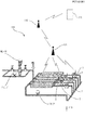
- the trap operating state management system 100 is a system that manages the operation states of a large number of steam traps T distributed in a process system formed in a factory, a plant, or the like using wireless communication.
- the trap operation state management system 100 includes a trap operation state providing device (terminal device) 110, a trap operation state management device (management device) 120, and a communication relay device 130.
- terminal device an electronic device
- trap operation state management device management device
- communication relay device 130 In FIG. 1, a part of the trap operation state providing device 110 and the communication relay device 130 included in the trap operation state management system 100 are shown.
- the trap operation state management system 100 performs firmware update management of the trap operation state providing device (terminal device) 110.
- the trap operation state management device 120 acquires the operation state from the trap operation state providing device 110 via the communication relay device 130, thereby managing the operation state of each steam trap T and determining the operation state.
- the trap operation state management device 120 wirelessly transmits update firmware data to each trap operation state providing device 110, and the firmware of the firmware is transmitted to each trap operation state providing device 110. Update is executed.
- the trap operation state management device 120 uses the unicast (one-to-one communication) and the broadcast (one-to-many communication) in combination to reduce the communication band and the battery while ensuring the reliability. High data transmission. Details will be described later.
- the firmware includes a program such as an OS (Operating System) stored in the memory 110b of the trap operation state providing device 110, for example.
- unicast refers to a communication method in which a single communication partner is designated (a single address is designated) in a network to perform one-to-one communication.
- Broadcast is an example of one-to-many communication, and is a communication in which data is simultaneously transmitted (unilaterally transmitted) to an unspecified number of communication partners using a broadcast address in a network (for example, the same LAN). Refers to the method.
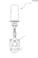
- the trap operating state providing device 110 is installed in each steam trap T constituting the process system. Each trap operation state providing device 110 is attached to the steam trap T as shown in FIG. 3 and acquires (measures) the operation state of the steam trap T. When the predetermined time is reached for each trap operation state providing device 110, the trap operation state providing device 110 transmits the acquired operation state (operation state information) to the communication relay device 130 with which the trap operation state providing device 110 communicates directly. . The trap operation state providing device 110 receives firmware data from the trap operation state management device 120 and updates the firmware.
- the communication relay device 130 temporarily holds the operation state information acquired from the trap operation state providing device 110, and when the relay operation state provision time predetermined for each communication relay device 130 is reached, the acquired operation state is trapped. It transmits to the state management apparatus 120.
- the communication relay device 130 receives the operation state of the communication relay device 130 located in the lower order when the communication relay device 130 located lower than the communication relay device 130 provides the operation state to the trap operation state management device 120. Relay transmission is performed to the communication relay device 130 or the trap operation state management device 120.
- the trap operation state providing apparatus 110 includes a CPU 110a, a memory 110b, a wireless communication circuit 110h, a sensor communication circuit 110i, and a time measuring circuit 110j.
- the CPU 110a performs processing based on other applications such as an operating system (OS), status information provision, and data update program stored and held in the memory 110b.
- the memory 110b includes a RAM and an EEPROM.
- the RAM provides a work area for the CPU 110a.
- the EEPROM includes an operating system (OS) and other programs such as status information provision and data update program (firmware), various data such as operating status information (see FIG. 13), operating status relay time information (see FIG. 12), and the like. Is retained. Various data will be described later.
- the state information provision and data update program causes the trap operation state providing device 110 to acquire the operation state information of the steam trap T using various sensors and transmit it to the management device 120.
- the program also causes the trap operation state providing device 110 to receive update firmware (update firmware) from the trap operation state management device 120 and update the firmware.
- a firmware update data storage area 110b-1 and a memory map area 110b-2 are set in the EEPROM.
- the update data storage area 110b-1 is an area for storing and holding update firmware transmitted from the trap operation state management device 120.
- the firmware data for update transmitted from the trap operating state management device 120 is first stored and held in the update data storage area 110b-1, and then the corresponding firmware storage area is received on the condition that rewrite permission is received. Can be rewritten.
- the memory 110b (EEPROM) corresponds to a received data storage unit.
- the memory map area 110b-2 is an area for storing and holding a memory map (see FIG. 17) of the firmware for update stored in the update data storage area.
- the memory map is information indicating the reception status (storage status) of update firmware data from the trap operating status management device 120.
- the update firmware data transmitted from the trap operation state management device 120 may be simply referred to as firmware.
- the wireless communication circuit 110h transmits / receives data to / from an external communication device such as the trap operation state management device 120 by wireless communication (packet communication).
- the sensor communication circuit 110i is connected to various sensors such as a temperature sensor and a vibration sensor arranged in the trap operation state providing device 110, and acquires operation state information of the steam trap T from the various sensors.
- the timer circuit 110j generates a predetermined clock and measures a predetermined time.
- the CPU 110a and the wireless communication circuit 110h correspond to the second communication control unit of the present invention.
- the trap operation state management device 120 includes a CPU 120a, a memory 120b, a hard disk drive 120c (hereinafter referred to as HDD 120c), a keyboard 120d, a mouse 120e, a display 120f, an optical drive 120g, a wireless communication circuit 120h, And it has the time measuring circuit 120j.
- the CPU 120a performs processing based on other applications such as an operating system (OS) stored in the HDD 120c, a trap operation state information management program, a firmware transmission program (data transmission program), and the like.
- the memory 120b provides a work area for the CPU 120a.
- the HDD 120c stores and holds other application programs such as an operating system (OS), a trap operation state information management program, and a firmware transmission program. Further, the HDD 120c has an operation state information database (hereinafter referred to as an operation state information DB) (see FIG. 14), time slot setting time information (see FIG. 8), time slot allocation information (see FIG. 9), network configuration information (see FIG. 9). (See FIG. 10).
- OS operating system
- DB operation state information database
- the trap operation state information management program causes the trap operation state management device 120 to acquire operation state information from the trap operation state providing device 110 and manage the operation state of each steam trap T.
- the firmware transmission program causes the trap operation state management device 120 to transmit update firmware data to the trap operation state providing device 110 to instruct updating of the firmware.
- the HDD 120c also stores and holds data such as update firmware (transmission data), group information (see FIG. 15), data transmission progress information (see FIG. 16), and the like used when transmitting the update firmware.
- the HDD 120c corresponds to a transmission data storage unit.
- the keyboard 120d and mouse 120e accept external commands.
- the display 120f displays an image such as a user interface.
- the optical drive 120g reads the trap operation state information management program and the firmware update program from the optical medium 120p in which the trap operation state information management server program (not shown) is recorded, and others from other optical media. Read data from optical media, such as reading the application program.
- the wireless communication circuit 120h transmits / receives data to / from an external communication device such as the trap operation state providing device 110 by wireless communication (packet communication).
- the timer circuit 120j generates a predetermined clock and generates a time that is a reference for the trap operation state management device 120.
- the CPU 120a and the wireless communication circuit 120h correspond to the first communication control unit (communication control unit) of the present invention.
- the communication relay device 130 includes a CPU 130a, a memory 130b, a wireless communication circuit 130h, and a timer circuit 130j.
- the CPU 130a performs processing based on other applications such as an operating system (OS) and a communication relay program stored and held in the memory 130b.
- the memory 130b provides a work area for the CPU 130a.
- the memory 130b includes an operating system (OS), a program of another application such as a communication relay program, operating state information acquired from the trap operating state providing device 110, time slot setting time information (see FIG. 8), time Various data such as slot allocation information (see FIG. 9), network configuration information (see FIG. 10), and operating state relay time information (see FIG. 12) are stored and held. Various data will be described later.
- the wireless communication circuit 130h transmits / receives data (packet communication) to / from the trap operation state providing device 110, the trap operation state management device 120, and the other communication relay device 130.
- the timer circuit 130j generates a predetermined clock and measures a predetermined time. As the predetermined time, for example, the operation state acquisition time and the communication relay time are set in the time measuring circuit 130i. The operating state acquisition time and the communication relay time will be described later.
- the communication relay program causes the communication relay device 130 to receive the operation state information from the trap operation state providing device 110 and transmit it to the trap operation state management device 120.
- the program causes the communication relay device 130 to receive the operation state information of the communication relay device 130 positioned at the lower level and relay-transmit it to the higher-level communication relay device 130 or the trap operation state management device 120.
- Communication Time Management in Fifth Trap Operating State Management System 100 Communication time management used in the trap operating state management system 100 will be described with reference to FIG.
- a time slot system using a communication management time called a time slot is applied, and the trap operation state management device 120 receives the operation state information from the trap operation state providing device 110 via the communication relay device 130. To get.
- a time slot that is a communication time zone obtained by dividing a predetermined operation state acquisition cycle time into a predetermined length of time is assigned to all communication relay devices 130 belonging to the trap operation state management system 100.
- the communication relay device 130 manages the communication time for communicating with other communication devices.
- the operation state acquisition cycle time refers to an acquisition interval time when the trap operation state management system 100 repeatedly acquires an operation state from a certain communication relay device 130.
- the trap operation state providing device 110 and the communication relay device 130 are activated to perform communication when the communication time period is reached, and enter a sleep state during other time periods (when the communication time period ends) to perform communication. It becomes a state not to do. That is, the communication time is managed by the time slot system, and the activation and sleep of the trap operation state providing device 110 and the communication relay device 130 are repeatedly performed.
- the trap operation state management device 120 will be described as a state after being activated.
- the firmware data transmission by the trap operation state management device 120 is also transmitted to the trap operation state providing device 110 via the communication relay device 130, it is performed in the communication time zone managed in the time slot system. Is called. Therefore, first, communication time management in the trap operation state management system 100 will be described in detail.
- the length TW of the time slot TS becomes fB / N time.
- N is normally set to a number larger than the number of communication relay devices 130 belonging to the trap operation state management system 100.
- the time slot TS is assigned with a time slot number for specifying each in order from the start of the operation state acquisition cycle time fB.
- the N0th time slot TS from the start of the operating state acquisition cycle time fB is denoted as a time slot TS (N0).
- the operating state acquisition cycle time fB can assign the time slot TS of length TW to all the communication relay devices 130 belonging to the trap operating state management system 100 after setting the length TW of the time slot TS. Set the time.
- the length TW of the time slot TS indicates the number of trap operation state providing devices 110 belonging to one communication relay device 130, the number of communication relay devices 130 belonging to the trap operation state management system 100, the communication status between the devices, and the like. To be determined.
- the time slot to which each time slot TS is allocated is described in the time slot setting time information (see FIG. 8).
- the time slot TS is assigned to each communication relay device 130. Which time slot TS is assigned to which communication relay device 130 is described in time slot assignment information (see FIG. 9).
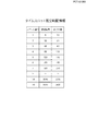
- Time Slot Setting Time Information is information describing the start time and end time of each time slot TS.
- the time slot setting time information is provided to each of the communication relay devices 130 by the trap operation state management device 120, and each communication relay device 130 stores and holds the information in the memory 130b.
- the time slot setting time information has a slot number description area, a start time description area, and an end time description area.
- the slot number description area the slot number of the time slot TS set in the trap operation state management system 100 is described.
- the start time description area the time at which the time slot TS specified by the slot number starts is described.
- the end time description area the time at which the time slot TS specified by the slot number ends is described. Note that the time at which the time slot TS starts and the time at which the time slot TS ends are described as the elapsed time from the start of the operating state acquisition cycle time fB.
- the time slot TS (3) of the slot number “3” starts “after 60 seconds” after a certain operation state acquisition cycle time fB starts. It indicates that the process ends after 90 seconds.
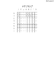
- Time Slot Allocation Information is information describing the communication relay device 130 allocated to each time slot.
- the time slot allocation information is provided to each of the communication relay devices 130 by the trap operation state management device 120, and each communication relay device 130 stores and holds it in the memory 130b.
- FIG. 9 shows the data structure of the time slot allocation information.
- the time slot allocation information has a slot number description area and a process system component device ID description area.
- the slot number description area a slot number set in each time slot TS in the trap operation state management system 100 is described.
- the process system component device ID description area the process system component device ID of the communication relay device 130 assigned to the time slot TS specified by the slot number is described.
- the time slot TS (3) with the slot number “3” in FIG. 9 indicates that the communication relay device 130 with the process system component device ID “R2” is assigned.
- the network configuration information is information describing the network configuration of the communication relay device 130 belonging to the trap operation state management system 100.
- the network configuration information is provided to each of the communication relay devices 130 by the trap operation state management device 120, and each communication relay device 130 stores and holds it in the memory 130b.
- the data structure of the network configuration information is shown in FIG.
- the network configuration information has a lower process system configuration device ID description area and an upper process system configuration device ID description area.
- the process system component device ID of one communication relay device 130 belonging to the network of the trap operation state management system 100 is described.
- the network configuration information will be described by taking the network configuration of the trap operation state management system 100 shown in FIG. 11 as an example.
- an ID for identifying each device is also described.
- the communication relay device 130 with the process system component device ID “R4” is directly below the communication relay device 130 with the process system component device ID “R3”. Located in. That is, the communication relay device 130 having the process system component device ID “R3” is directly above the communication relay device 130 having the process system component device ID “R4”. Therefore, as in the network configuration information shown in FIG. 10, “R3” is described in the upper process system configuration device ID description area corresponding to the value of the lower process system configuration device ID description area “R4”.
- Operation state relay time information is information indicating a time zone for the trap operation state providing device 110 to provide the operation state information to the communication relay device 130.
- the operation state relay time information is stored and held in the memory 110b of the communication relay device 130 and the trap operation state providing device 110.
- Fig. 12 shows the data structure of operating state relay time information.
- the operating state relay time information has a process system component device ID description area, a start time description area, and an end time description area.
- the process system component device ID description area the process system component device ID set in the trap operation state providing device 110 that directly belongs to the communication relay device 130 is described.
- the start time description area a time at which the communication relay device 130 starts communication with the trap operation state providing device 110 specified by the process system component device ID is described.
- the end time description area the time for ending communication with the trap operation state providing device 110 specified by the process system component device ID is described.
- the time for starting communication and the time for ending communication with the trap operation state providing device 110 are directly set to the communication relay device 130 with which the trap operation state providing device 110 communicates, that is, the trap operation state providing device 110. Is described as the elapsed time calculated from the start of the time slot TS of the communication relay device 130 located at the upper level.
- the trap operation state providing device 110 having the process system component device ID “T5” directly communicates with the communication relay device 130 having the process system component device ID “R4” positioned at the upper level. It shows that the time slot TS (R4) of (see FIG. 11) starts “after 0.5 seconds” and ends after “1 second”.
- the trap operation state providing device 110 basically operates during a period from the start of communication to the end of communication, and enters a sleep state after the end of the communication end time. Further, in this communication, the communication relay device 130 obtains the operation state information by making a transmission request for the operation state information to the trap operation state providing device 110.
- the operation state relay time information shown in FIG. 12 provides the communication relay device 130 with the process system component device ID “R4” and the trap operation state of the process system component device IDs “T4”, “T5”, and “T6”. It is stored and held in the device 110. Then, the trap operation state providing device 110 having the process system component device IDs “T4”, “T5”, and “T6” transmits the operation state information to the communication relay device 130 having the process system component device ID “R4”. That is, the trap operation state providing device 110 transmits the operation state information directly to the communication relay device 130 positioned at the upper level.
- the other communication relay device 130 or the like stores operating state relay time information for which another time is set.
- Operating state information is information indicating an operating state of the steam trap T at a predetermined time, for example, temperature and vibration.
- the operating state information is acquired by the trap operating state providing device 110 via various sensors, and is stored and held in the memory 110b.
- Fig. 13 shows the data structure of the operating state information.
- the operating state information has an operating state type description area, an operating state value description area, and an operating state value acquisition time description area.
- the operating state type description area the type of operating state is described.
- the operating state value description area the sensor value of the sensor used when acquiring the operating state is described.
- the operating state value acquisition time description area the time indicated by the clock circuit 110j when the operating state value is acquired is described.
- Operating state information DB is information in which the operating state of the steam trap T belonging to the trap operating state management system 100 is accumulated.
- the operation state information DB is generated by the trap operation state management device 120 based on the operation state information of the steam trap T acquired through each trap operation state providing device 110, and is stored and held in the HDD 120c.
- Fig. 14 shows the data structure of the operating state information DB.
- the operation state information DB has a process system component device ID description area, an operation state type description area, an operation state value description area, an operation state value acquisition time description area, and a reception time description area.
- a process system configuration device ID description area a process system configuration device ID that uniquely identifies the process system configuration device that has acquired the operation state information is described.
- the operating state type description area and the operating state value description area information indicating the type of the acquired operating state information (see FIG. 13) and information indicating the state value are described.
- the operating state value acquisition time description area information indicating the operating state value acquisition time of the acquired operating state information (see FIG. 13) is described.
- the reception time description area the time indicated by the timer circuit 120j when the operating state information is received is described.
- Group information is information indicating the trap operation state providing device 110 located directly below each communication relay device 130. That is, the information indicates the trap state providing apparatus 110 grouped with the communication relay apparatus 130 as a reference.
- the group information is information for specifying the communication relay device 130 and the trap operation state providing device 110 that transmit the operation state information.
- the group information is stored and held in the HDD 120c of the trap operation state management device 120.
- the data structure of group information is shown in FIG.
- the group information has an upper process system configuration device ID description area and a lower process system configuration device ID description area.
- the process system component device ID of the communication relay device 130 is described in the upper process system component device ID (group ID) description area.
- the lower process system component device ID (belonging device ID) description area the trap operation directly located in the lower level in the communication relay device 130 corresponding to the process system component device ID described in the upper process system component device ID description area
- the process system component device ID of the state providing apparatus 110 is described.
- the trap operation state providing device 110 having the process system configuration device IDs “T4”, “T5”, and “T6” is set. Yes.
- the trap operating state management device 120 refers to the group information and causes the trap operating state providing device 110 to update the firmware in units of groups.
- the data transmission progress information is information indicating a progress status of firmware update for each group based on the communication relay device 130.
- the data transmission progress information is stored and held in the HDD 120c of the trap operation state management device 120.
- the data structure of the data transmission progress information is shown in FIG.
- the data transmission progress information has an upper process system component device ID description area, a status description area, a transmitted address description area, a response apparatus ID description area, a reception status description area, and a retransmission address description area.
- the process system component device ID of the communication relay device 130 is described as in FIG.
- the transmitted address description area the address of the data that has been transmitted among the data constituting the firmware is described.
- the firmware data is divided and transmitted in units of a predetermined size (for example, 50 bytes) in order from the data of the head address. Then, the final address that has already been divided and transmitted is described in the transmitted address description area. Therefore, when transmitting the firmware data next time, the trap operation state management device 120 performs divided transmission from the data at the address next to the address described in the transmitted address description area.
- the response device ID description area describes the process system component device ID of the trap operation state providing device 110 that has received a reply to the start of firmware update to each trap operation state providing device 110 belonging to each group. Is done. Only the trap operation state providing device 110 that has returned is recognized as the trap operation state providing device 110 to be updated (transmitted).
- the reception status description area describes a reception status (memory map) for each trap operation status providing device 110 (response device ID) to be updated.
- an address for specifying firmware data to be retransmitted for each trap operation state providing apparatus 110 (response device ID) to be updated is described. That is, an address for specifying firmware data (retransmission data) that the trap operation state providing apparatus 110 cannot receive is described.
- the address of the retransmission data is specified from the memory map.
- the memory map is information indicating the storage status of firmware data stored in the update data storage area of the trap operation state providing device 110.
- the memory map is stored and held in the memory 110b of the trap operation state providing device 110.
- the data structure of the memory map is shown in FIG.
- the memory map has, for example, a size of 8 bytes, and stores the storage status of the update firmware for each bit.
- FIG. 17 is a memory map of an 8 ⁇ 8 array structure displayed in binary. The right end is the least significant bit and the left end is the most significant bit. For example, when the size of the firmware is 64 kilobytes, the storage status of firmware data for 1 kilobyte is stored for each bit. Bit 0 in the 0th column describes the storage status of data from the first address of the firmware to the first kilobyte address.
- bit 0 of the 0th column describes “1” as a numerical value
- the data from the head address to the address of the first kilobyte indicates the state stored in the data update area.
- Bit 2 in the first column indicates a state in which data in the corresponding address range cannot be stored in the data update area because “0” is described as a numerical value.
- Operation of the seventh trap operation state management system 100 Operation of communication relay device 130 (1) Operation time setting process
- the communication relay device 130 is stored in the memory 130b when the operation time is not set in the timer circuit 130j, such as when it operates for the first time.
- the time slot setting time information see FIG. 8
- the time slot allocation information see FIG. 9
- the network configuration information see FIG. 10.
- the operating time is set in the clock circuit 130j.
- the communication relay device 130 is in a so-called sleep state except for the time measuring circuit 130j for a time other than the time set as the operation time.
- the operation time setting process will be described with reference to the flowchart shown in FIG.
- the CPU 130a of the communication relay device 130 acquires the slot number of its own time slot TS from the time slot allocation information stored and held in the memory 130b (S1501).
- the CPU 130a acquires the start time and end time of its own time slot TS from the time slot setting time information stored and held in the memory 130b (S1503).
- the CPU 130a sets the acquired start time and end time as the operating state acquisition time in the timer circuit 130j (S1505).
- the CPU 130a acquires the communication relay device 130 belonging to the lower level from the network configuration information (S1507). Specifically, the CPU 130a extracts its own process system configuration device ID from the upper process system configuration device ID description area of the network configuration information, and acquires the process system configuration device ID of the corresponding lower process system configuration device ID description area. To do. The CPU 130a extracts the acquired process system configuration device ID from the upper process system configuration device ID description area of the network configuration information, and acquires the process system configuration device ID in the corresponding lower process system configuration device ID description area. The CPU 130a repeats the above operation until the acquired process system configuration device ID does not exist in the upper process system configuration device ID description area of the network configuration information. In addition, when the own process system configuration device ID does not exist in the upper process system configuration device ID description area of the network configuration information, it indicates that the communication relay device 130 is located at the end.
- the CPU 130a acquires the slot number of the time slot TS of the communication relay device 130 belonging to the lower level from the slot allocation information stored and held in the memory 130b (S1509).
- the CPU 130a acquires the start time and end time of the time slot TS of the communication relay device 130 belonging to the lower level from the time slot setting time information stored and held in the memory 130b (S1511).
- the CPU 130a sets the acquired start time and end time as the communication relay time in the timer circuit 130j (S1513).
- the CPU 130a acquires the value “R4” of the lower process system configuration device ID description area corresponding to the value “R3” of the upper process system configuration device ID description area of the network configuration information, and acquires the value from the slot allocation information.
- the slot number “5” of the time slot TS corresponding to the process system component device ID “R4” is acquired.
- the CPU 130a sets the start time “120” and the end time “150” of the slot number “5” in the time measuring circuit 130j as the communication relay time from the time slot setting time information.
- the CPU 130a acquires the slot number “5” of its own time slot TS from the slot allocation information. Then, the CPU 130a sets the start time “120” and the end time “150” of the slot number “5” from the time slot setting time information as the operating state acquisition time in the time measuring circuit 130j.
- the CPU 130 a Since the value of the lower process system component device ID description area corresponding to the value “R4” of the upper process system component device ID description area of the network configuration information does not exist, the CPU 130 a The communication relay time is not set in the timing circuit 130j.
- Operational state acquisition / transmission process is a process executed by the communication relay device 130, and the communication relay device 130 between the communication relay device 130 and the trap operation state providing device 110.
- the operation status information is acquired from the trap operation state providing device 110 that communicates directly and communicates directly, and the operation state information acquired by the communication relay device 130 is transmitted to the trap operation state management device 120.
- the communication relay device 130 acquires the operation state information from the trap operation state providing device 110 within the time slot TS corresponding to itself, and then traps the acquired operation state information. It transmits to the state management apparatus 120.
- the allocation of time to each process in the time slot TS is shown in FIG.
- the communication relay device 130 acquires operation state information from the trap operation state providing device 110 that is positioned below itself and can communicate directly.
- the communication relay device 130 that communicates transmits the acquired operation state information to the trap operation state management device 120 in the period t2 following the period t1.
- a period t3 following the period t1 and the period t2 is allocated as a spare unit period and is used as appropriate.
- the communication relay device 130 measures the time from the start of the operation state acquisition cycle time fB in the current cycle by using the timing circuit 130j.
- the time measuring circuit 130j of the communication relay device 130 determines that the time being measured is the operating state acquisition time (S2301), it transmits operating state acquisition transmission process start information to the CPU 130a (S2303). That is, it shows a state in which the period t1 in the time slot TS is started. Note that the timer circuit 130j activates the CPU 130a when the CPU 130a of the communication relay device 130 is in the sleep state.
- the CPU 130a determines whether an extension request has been received from the trap operation state management device 120 (step S2304).
- the extension request is information for extending the operation time at the next start-up of the trap operation state providing apparatus 110 that is positioned below itself and can communicate directly.
- the trap operation state providing device 110 enters the sleep state after the operation from the start time to the end time set as shown in FIG. 12 in the period t1 in the time slot TS, and does not perform communication. Thus, the end time is until the end time of the period t3 of the time slot TS.
- the extension request is information transmitted for firmware update. Details will be described later.
- the CPU 130a determines that the extension request has not been received in S2304, the CPU 130a obtains the operation state information from the trap operation state providing device 110 that is located under the device and can communicate directly (S2305). More specifically, the CPU 130a starts timing using the timing circuit 130j, and provides the trap operation state by referring to the time measured and the start time and end time of the operation state relay time information (see FIG. 12). Requests for transmission of operating state information are sequentially transmitted to the device 110. Then, the operation state information is acquired from each of the trap operation state providing devices 110 by the end of the period t1 of the time slot TS.
- the CPU 130a determines that an extension request has been received in S2304, the CPU 130a makes an extension request to the trap operation state providing apparatus 110 that is positioned below and can communicate directly (S2306) and acquires operation state information (S2306). ). More specifically, the CPU 130a starts measuring time using the time measuring circuit 130j as in S2305 described above, and refers to the time measured and the start time and end time of the operating state relay time information (see FIG. 12). Then, an extension request and an operation state information transmission request are sequentially transmitted to the trap operation state providing device 110.
- the CPU 130a temporarily stores and holds the received operation state information in the memory 130b together with the reception time in association with the transmission source trap operation state providing device 110 (S2307). Then, the CPU 130a transmits the operation state information temporarily stored in the memory 130b to the trap operation state management device 120 within the period t2 after the end of the period t1 of the time slot TS (S2309).
- the start time of the next communication relay time is not a time that is continuous with the current operation state acquisition time. (S2313) Except for the timing circuit 130j, the sleep state is set (S2315). On the other hand, if the start time of the next communication relay time is continuous with the current operating state acquisition time, communication relay processing (described later: see FIG. 21) is executed (S2317).
- the communication relay processing is a trap from a certain communication relay device 130 when a certain communication relay device 130 transmits operation state information to the trap operation state management device 120 using a time slot system. This is a process in which the communication relay device 130 existing on the communication path to the operation state management device 120 relays the transmission of the operation state information.
- the communication relay process obtaining process will be described with reference to the flowchart shown in FIG.
- the time measuring circuit 130j of the communication relay device 130 determines that the time being measured is the start time of the communication relay time (S2401), it transmits communication relay processing start information to the CPU 130a (S2403). Note that the timer circuit 130j activates the CPU 130a when the CPU 130a of the communication relay device 130 is in the sleep state.
- the CPU 130a transmits (relays) the operating state information acquired via the wireless communication circuit 110h to its upper communication relay device 130 (S2405). If the CPU 130a determines that the end time of the communication relay time has come (S2407), the start time of the operation state acquisition time is not a time continuous with the current communication relay time (S2409), and the next communication relay time If the start time is not a continuous time with the current communication relay time (S2411), the clock circuit 130j is excluded and the sleep state is set (S2413).
- step S2409 if the start time of the operation state acquisition time is a time continuous with the current communication relay time in step S2409, the CPU 130a executes the operation state acquisition transmission process (see FIG. 20) (S2415). If the start time of the next communication relay time is continuous with the current communication relay time in step S2411, the CPU 130a repeats the processing from step S2401.
- the communication relay device 130 is operating during the operation state acquisition time and the communication relay time, and enters a sleep state at other times. For example, when the communication relay device 130 having the system configuration device ID “R2” illustrated in FIG. 11 is in the operation state acquisition time, the communication relay device 130 having the system configuration device ID “R1” is also operated corresponding to the communication relay time. It becomes a state. Further, the trap operation state providing device 110 of the system configuration device IDs “T1”, “T2”, and “T3” that are directly below the system configuration device ID “R2” also starts the start time based on the operation state relay time information. It will be in the state of operating at the end time.
- Trap Operating State Providing Device 110 uses the time measuring circuit 110j to measure the time until the next operation state information is transmitted to the communication relay device 130.
- the trap operation state providing device 110 is in a state of operating from the start time to the end time in the operation state relay time information. Then, in the trap operation state providing device 110, after transmitting the operation state information to the communication relay device 130, when the end time in the operation state relay time information arrives, the CPU 110a, the wireless communication circuit 110h, and the like other than the time measuring circuit 110j are started.
- the predetermined circuit is set to the sleep state. When an extension request is made, the sleep state is entered after the operating time is extended to the period t3 of the time slot TS instead of the end time.
- the CPU 110a in the sleep state is activated (S2503). ).
- the extension flag is a variable that determines whether or not the operation time of the trap operation state providing device 110 is extended, and is set to a value of 1 (with extension) or 0 (without extension).
- the extension flag 0 is set as an initial value.
- the CPU 110a sets the end time to the end time of the operating state relay time information (S2511).
- the CPU 110a acquires operating state information from various sensors such as a temperature sensor and a vibration sensor via the sensor communication circuit 110i (S2513). And CPU110a transmits the acquired operation state information according to the transmission request
- requirement of the operation state information of the communication relay apparatus 130 located in the upper rank (S2515). Thereafter, the CPU 110a determines whether or not an extension request at the next start-up has been received from the communication relay device 130 positioned at the upper level (S2517). Specifically, it is determined whether or not the extension request information is also received from the communication relay device 130 located at the upper level when the operation state information transmission request is received. When receiving the extension request, the CPU 110a sets the extension flag 1 (S2519), and proceeds to the processing of S2521. As a result, in the trap operation state providing device 110, the end time (operation time) at the next activation is extended to the period t3.
- the CPU 110a determines whether the end time has arrived (S2521). When the end time has arrived, the CPU 110a puts the sleep state for a predetermined circuit including itself (S2523). Note that the CPU 110a obtains the time until the next operation state information is transmitted to the communication relay device 130 from the upper communication relay device 130 before going into the sleep state, and sets it in the timing circuit 110j. .
- the CPU 110a executes a firmware update process (see FIG. 23) (S2525).
- the firmware update process will be described later.
- Trap operating state management device 120 receives the operating state information from each trap operating state providing device 110 through the above-described operating state acquisition and transmission process, and updates the operating state information DB shown in FIG. To do. Further, when it is necessary to cause the trap operation state providing apparatus 110 to update the firmware, a firmware transmission process is performed. As described above, the firmware update is performed by the trap operation state providing device 110 of each group based on the group information and information on the communication time zone (time slot setting time information, time slot allocation information, network configuration information). It is performed at the timing (communication time zone).
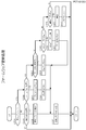
- the operation of the trap operation state management device 120 in the firmware transmission process will be described with reference to the flowchart shown in FIG.
- the trap operating state management device 120 uses the timing circuit 120j to measure the time from the start of the operating state acquisition cycle time fB in the current cycle.
- the firmware transmission process is executed when, for example, the operator inputs a firmware update instruction by operating the keyboard 120d, and the firmware update (rewrite) of all the trap operation state providing devices 110 that have responded is started. ) Is finished when it is completed. Further, the firmware transmission process shown in FIG. 24 is repeatedly executed at a constant cycle (for example, 10 milliseconds).
- the CPU 120a proceeds to any one of the start process (S2607), the transmission process (S2609), and the rewrite process (S2611) according to the status (S2605).
- FIG. 25 is a flowchart of a subroutine showing the start processing of S2607.
- the start process is a process for transmitting a start notification or the like for transmitting update firmware to the group's trap operation state providing apparatus 110.
- the CPU 120a determines whether the current time slot TS is within a predetermined time from the start of the period t1 (S2703).
- the predetermined time is set to a time before the group communication relay device 130 makes a transmission request for operating state information to the trap operating state providing device 110 in the period t1. This is because it is determined in S2703 whether or not it is a time zone in which an extension request can be made to the trap operation state providing apparatus 110 via the communication relay apparatus 130 performed in S2705.
- the extension request is transmitted from the trap operation state management device 120 (CPU 120a) to the communication relay device 130 in S2705. Then, the communication relay device 130 that has received the extension request makes an extension request to the trap operation state providing device 110 together with the transmission request of the operation state information in the period t1, as described in steps S2304 and S2306 shown in FIG. Therefore, the trap operation state management device 120 (CPU 120a) needs to make an extension request before the communication relay device 130 makes a transmission request for operation state information in the period t1 (within a predetermined time period t1).
- the CPU 120a transmits an extension request by unicast to the communication relay device 130 of the group (S2705).
- the communication relay device 130 that has received the extension request issues a request for extending the operating time at the next startup together with a request for transmitting the operating state information to the trap operating state providing device 110 belonging to the group.
- the CPU 120a updates the status from “0” (no progress) to “1” (update preparation complete) (S2707), and ends the start process.
- the CPU 120a determines in S2703 that the predetermined time has elapsed since the start of the period t1, the CPU 120a ends the start process.
- the CPU 120a determines whether the current time slot TS is after the period t2 (S2709). This is because in the present embodiment, communication with the trap operation state providing apparatus 110 relating to firmware update is performed in the periods t2 and t3. If the CPU 120a determines that the period is after the period t2, the CPU 120a transmits a firmware transmission start notification and a request for extending the operating time at the next start-up to each of the trap operation state providing devices 110 of the group by unicast (S2711). .
- the CPU 120a describes the trap operation state providing device 110 that has responded to the start notification in the response device ID description area of the corresponding group in the data transmission progress information of FIG. 16 (S2713). Then, the CPU 120a updates the status from “1” (update preparation completion) to “2” (transmission start) (S2715), and ends the start process. On the other hand, if the CPU 120a determines in S2709 that it is not after the period t2, the CPU 120a ends the start process.
- FIG. 26 is a flowchart of a subroutine showing the transmission process of S2609.
- the transmission processing is processing for dividing and transmitting update firmware by broadcast according to the transmission status of the firmware of the group.
- the CPU 120a determines whether the current time slot TS is after the period t2 (S2801). When it is not after the period t2, the CPU 120a ends the transmission process. As described above, in this embodiment, the communication with the trap operation state providing apparatus 110 related to the firmware update is performed in the periods t2 and t3. On the other hand, if it is after the period t2, the CPU 120a acquires a part of the firmware to be divided and transmitted next based on the transmitted address information of the corresponding group of the data transmission progress information (S2803), and acquires the acquired data. The address information and a request for extending the operating time at the next activation are transmitted by broadcast (S2805). Thereby, the trap operation state providing apparatus 110 receiving the group start notification stores the received data in the update data storage area based on the address information.
- the CPU 120a determines whether transmission of all data (final address data) of the update firmware is completed (S2807). When the transmission is completed, the CPU 120a updates the status from “2” (transmission start) to “3” (transmission completion) (S2809), and ends the transmission process. On the other hand, if the transmission has not been completed, the CPU 120a updates the transmitted address information of the group data transmission progress information to the address information that identifies the divided data that could be transmitted in S2805 (S2811), and performs the transmission process. finish.
- FIG. 27 is a flowchart of a subroutine showing the rewriting process in S2611.
- the rewriting process determines whether or not all data of the update firmware has been received for the trap operation state providing device 110 of the group that has responded to the start notification, and performs retransmission if it has not been received. If received, it is a process for executing a firmware rewriting process.
- the CPU 120a determines whether the current time slot TS is after the period t2 (S2901). As described above, in this embodiment, the communication with the trap operation state providing apparatus 110 related to the firmware update is performed in the periods t2 and t3. When it is not after the period t2, the CPU 120a ends the transmission process. On the other hand, if it is after the period t2, the CPU 120a determines which of the processes of S2905, S2911, and S2923 to shift to based on the status (S2903).
- the CPU 120a stores each memory map of the trap operation state providing device 110 (response device ID) of the group that has responded to the start notification. Based on the above, it is determined whether all data of the firmware is stored in each trap operation state providing device 110 (S2911). If the CPU 120a determines that all the firmware data is stored, the CPU 120a transmits a rewrite permission to each of the trap operation state providing devices 110 by unicast (S2913). Then, the CPU 120a updates the status from “4” (during determination) to “6” (update completion) (S2915), and ends the rewriting process.
- the CPU 120a determines that all firmware data is not stored, the CPU 120a transmits a request for extending the operating time at the next start-up to the trap operation state providing apparatus 110 by unicast (S2917).
- the CPU 120a stores address information indicating the divided data to be retransmitted in the firmware in the retransmission address information description area of the trap operation state providing device 110 (response device ID) (S2919). That is, a retransmission range is set.
- the CPU 120a updates the status from “4” (during determination) to “5” (during retransmission) (S2921), and ends the rewriting process.
- the CPU 120a sends the firmware based on the retransmission address information to the trap operation state providing device 110 of the group response device ID in the data transmission progress information.
- the data is transmitted by unicast together with the address information and a request for extending the operating time at the next activation (S2923).
- the CPU 120a determines whether transmission of all the retransmission data has been completed (S2925). When the re-transmission of all data is completed, the CPU 120a updates the status from “5” (retransmitting) to “3” (transmission completed) (S2927), and ends the rewriting process. The reason why the status is updated to “3” (transmission completed) is to determine again whether or not the rewrite permission can be transmitted by receiving the memory map after the retransmission. In addition, after completion of transmission of all data to be retransmitted, a rewrite permission may be transmitted.
- the CPU 120a updates the retransmission address information description area so as to exclude the address information of the data transmitted in S2923 (that is, sets the retransmission range) (S2929), and ends the rewriting process. To do.
- FIG. 23 shows a flowchart of a subroutine showing the firmware update process of S2525. As shown in FIG. 22, the firmware update process is performed after the transmission of the operation state information, and is repeatedly executed until the end time comes in S2521 and the sleep state is set (S2523).
- the start flag is a variable that specifies whether or not a firmware update start notification has been received from the trap operation state management device 120, and is set to a value of 1 (received) or 0 (not received). . 0 is set as an initial value. Further, whether to update the firmware is determined according to the value of the start flag. Specifically, if no start notification is received, no data is received even if firmware data is transmitted from the trap operation state management device 120 by broadcast.
- the CPU 130a determines whether the firmware data by broadcast has been received from the trap operation state management device 120 (S2559). If received, the CPU 130a stores the received data in the update data storage area based on the received address information (S2561), and updates the reception status (memory map) (S2563). Then, the CPU 130a proceeds to S2557, sets the extension flag, and ends the firmware update process.
- the CPU 130a determines whether a transmission request for the reception status (memory map) for itself is received from the trap operation state management device 120. (S2565). When the transmission request is received, the CPU 130a transmits the memory map together with its own system configuration device ID (S2567), proceeds to S2557, sets the extension flag, and ends the firmware update process.
- the CPU 130a determines whether or not unicast firmware retransmission data has been received from the trap operation state management device 120 (S2569).
- the CPU 130a stores the received retransmission data in the update data storage area based on the received address information (S2571), and updates the reception status (memory map) (S2573). Then, the CPU 130a proceeds to S2557, sets the extension flag, and ends the firmware update process.
- the CPU 130a determines whether the unicast rewrite permission is received from the trap operation state management device 120 (S2575). When the rewrite permission is received, the CPU 130a performs a rewrite process for describing the firmware stored in the update data storage area in the formal storage area of the memory 110b (S2577). As a result, the firmware rewriting process is completed, so the CPU 130a resets the start flag and the extension flag to “0” (S2579) and ends the firmware update process. If CPU 130a determines in S2575 that it has not received a rewrite permission for itself in unicast, it ends the rewrite process.
- the terminal device when transmitting firmware update data, the terminal device (trap operation state providing device 110) that has responded to the start notification is identified as the target of data transmission, and transmission data transmission completes. After that, whether or not transmission data can be received by unicast with respect to the specified trap operation state providing device 110 is confirmed by the reception status (memory map), and the data of the portion where transmission data cannot be received corresponds as necessary. To the trap operating state providing device 110 to be retransmitted. Therefore, since start and end communication in data transmission is performed by unicast and only transmission data transmission is performed by broadcast, data transmission with high reliability is achieved while realizing low wireless communication bandwidth and low battery consumption. It can be performed.
- the trap operation state providing device and the communication relay device according to the first embodiment described above are repeatedly activated and sleep in a cycle based on a time slot, but may be configured to always operate (communicate). Good. In this case, it is not necessary to make an extension request from the trap operation state management device, and it is not necessary to consider the transmission timing of the firmware data (after the period t2 of the time slot TS). In addition, it is not necessary to manage the data transmission progress information for each group. Further, it is not necessary to transmit firmware or the like during the operation state information acquisition transmission processing as in the first embodiment.
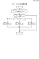
- the firmware can be rewritten by the processing shown in FIGS.
- the trap operation state management device (CPU) transmits a start notification by unicast to each of all trap operation state providing devices belonging to the trap operation state management system (S3001). Is stored in the HDD (S3003). Thereafter, the trap operation state management device (CPU) transmits the firmware data by broadcast (S3005). In this case as well, in the case of firmware of a size that cannot be transmitted at a time, it may be divided and transmitted.
- the trap operation state management device sends a reception status transmission request to the trap operation state providing device that has responded (S3007), and all data of the firmware for update is stored based on the received reception status. It is determined whether it is stored in the update data storage area. If stored, the trap operation state management device (CPU) transmits the rewrite permission to the trap operation state providing device that has responded by unicast (S3011). On the other hand, if not stored, the trap operating state management device (CPU) specifies the address range of the data to be retransmitted in the firmware based on the reception status (S3013), and transmits the data in the specified dress range as the retransmission data. (S3015).
- the reception status may be a memory map.
- the trap operation state providing device waits until it receives a start notification for itself (S3101).
- the trap operation state providing device transmits a response to the start notification (S3103).
- the trap operation state providing device performs processing according to the content received from the trap operation state management device until the rewriting is completed.
- the trap operation state providing device When it is determined in S3105 that firmware data has been received by broadcast, the trap operation state providing device (CPU) stores the received data in the update data storage area based on the received address information (S3107), and the reception status Is updated (S3109). If it is determined in S3111 that the reception status transmission request has been received, the trap operation state providing device (CPU) transmits the reception status (S3113).
- the trap operation state providing device stores the received retransmission data in the update data storage area based on the received address information (S3117), and displays the reception status. Update (S3119). If it is determined in S3121 that the rewrite permission has been received, the trap operation state providing device (CPU) rewrites the firmware (S3123) and ends the process.
- the trap operation state management apparatus of the first embodiment described above is the operation time until the end time in the time slot period t1, but may be in a state where it is always operating from the period t1 to t3. In this case, the trap operation state management device does not need to make an extension request to the trap operation state providing device.
- the memory map is used as the reception status, but any configuration may be applied as long as the reception status can be specified.
- the configuration of the memory map is not limited to the above configuration.
- all the trap operation state providing devices belonging to the trap operation state management system are the transmission targets of the update firmware, but some trap operation state providing devices may be the transmission targets. Good.
- the start notification may be transmitted to some trap operation state providing devices by unicast. The trap operating state providing apparatus that has not received the start notification does not store the received data because it has not received the start notification even when the update firmware data is received by broadcast thereafter.
- the trap operation state management system to which the data transmission system is applied has been described. However, as long as the management device and the terminal device communicate with each other via the communication relay device on the communication network. It is not limited to the trap operating state management system. Also, the data to be transmitted is not limited to firmware, and various data can be used.
- the trap operation state management system executes each process using the data shown in FIGS. 8 to 10 and FIGS. 12 to 17.
- the present invention is not limited to the examples as long as the functions and purposes of each process can be achieved.
- broadcast is used as an example of one-to-many communication, but multicast may be used instead of broadcast.
- Multicast is a communication method in which data is simultaneously sent (unilaterally transmitted) to a specific number of communication partners using a multicast address (address that specifies a plurality of specific nodes) within a network (for example, the same LAN). Say. In this case, multicast transmission may be performed with respect to the trap operation state providing apparatus 110 that has responded to the unicast firmware transmission start notification.
- the data transmission system according to the present invention is useful for performing highly reliable data transmission while using a one-to-one communication and a one-to-many communication to achieve a reduction in wireless communication bandwidth and battery consumption.
- it can be used for transmitting firmware of a trap operation state management system that manages the operation state of a steam trap in a steam plant.
- trap operation state management system 110 trap operation state providing device 110a CPU 110b Memory 110h Wireless communication circuit 110i Sensor communication circuit 110j Timing circuit 120 Trap operation state management device 120a CPU 120b Memory 120c Hard disk drive 120d Keyboard 120e Mouse 120f Display 120g Optical drive 120h Wireless communication circuit 120j Timing circuit 120p Optical media 130 Communication relay device 130a CPU 130b Memory 130h Wireless communication circuit 130j Timekeeping circuit T Steam trap
Landscapes
- Engineering & Computer Science (AREA)
- Computer Networks & Wireless Communication (AREA)
- Signal Processing (AREA)
- Selective Calling Equipment (AREA)
- Mobile Radio Communication Systems (AREA)
- Computer And Data Communications (AREA)
- Communication Control (AREA)
- Data Exchanges In Wide-Area Networks (AREA)
Abstract
Provided is a management device for transmitting data to a plurality of terminal devices via a communication relay device in a connected communications network and controlling the plurality of terminal devices, the management device being provided with a transmission data storage unit and a communication control unit. The transmission data storage unit stores transmission data. The communication control unit controls communication with the plurality of terminal devices. The communication control unit also: issues notification of the commencement of data transmission by one-to-one communication to each of the terminal devices to which data is to be transmitted among the plurality of terminal devices; receives a reply to the notification of commencement from a terminal device; after the notification of commencement, starts transmitting transmission data by one-to-many communication; and, after having finished transmitting the transmission data, requests by one-to-one communication that the reception state of the transmission data be transmitted from a terminal device from which there was a reply to the notification of commencement.
Description
この発明は、通信ネットワーク上で通信中継装置を経由して管理装置から複数の端末装置にデータ送信を行うデータ送信システム等に関する。
The present invention relates to a data transmission system for transmitting data from a management device to a plurality of terminal devices via a communication relay device on a communication network.
特開2014-207629号公報などに示されるように、通信ネットワーク上で複数の通信装置がパケット通信を行う場合には、ユニキャスト、マルチキャスト等の複数の通信形態が用いられる。
As disclosed in Japanese Patent Application Laid-Open No. 2014-207629, etc., when a plurality of communication devices perform packet communication on a communication network, a plurality of communication modes such as unicast and multicast are used.
また、特開2014-225897号公報などに示されるように、通信ネットワーク上で端末制御装置と端末装置とが、中継機(リピータ)を経由して無線でのパケット通信を行う構成もある。このような構成においては、端末装置のファームウェアの更新を行う場合、端末制御装置から端末装置に対して更新用のファームウェアのデータが送信される。このデータ送信においては、ユニキャスト、マルチキャスト又はブロードキャストのいずれかの通信形態が用いられていた。
Also, as disclosed in Japanese Patent Application Laid-Open No. 2014-225897, etc., there is a configuration in which the terminal control device and the terminal device perform wireless packet communication via a relay device (repeater) on the communication network. In such a configuration, when updating the firmware of the terminal device, the firmware data for update is transmitted from the terminal control device to the terminal device. In this data transmission, any one of unicast, multicast or broadcast communication forms has been used.
上述のような複数の端末装置にデータ送信される場合、ユニキャストでは端末装置の数が多いほど通信帯域を占有することとなり、中継機などでのバッテリー消費が増大する。また、マルチキャスト及びブロードキャストでは、通信帯域及びバッテリー消費を低減できるが、送信に対する各端末装置からのACK(acknowledgement)を要求できない。そのため、各端末装置がデータを受信したことが保障されない。特にファームウェアの更新などの重要なデータを送信する場合には、確実性の高い通信形態を採用する必要がある。
When data is transmitted to a plurality of terminal devices as described above, the larger the number of terminal devices in unicast, the more the communication band is occupied, and the battery consumption in the relay device and the like increases. In multicast and broadcast, communication bandwidth and battery consumption can be reduced, but ACK (acknowledgement) from each terminal device for transmission cannot be requested. Therefore, it is not guaranteed that each terminal device has received data. In particular, when transmitting important data such as firmware updates, it is necessary to adopt a highly reliable communication mode.
この発明は、1対1通信及び1対多通信を併用して、通信帯域及びバッテリーの低消費化を実現しつつ、確実性の高いデータ送信を行うことができるデータ送信システム等を提供することを目的とする。
The present invention provides a data transmission system and the like capable of performing highly reliable data transmission while realizing reduction in communication bandwidth and battery by using one-to-one communication and one-to-many communication. With the goal.
本発明の第1の側面によって提供されるデータ送信システムは、複数の端末装置と、該複数の端末装置を制御する管理装置と、該端末装置及び管理装置の通信を中継する通信中継装置とが通信ネットワークに接続され、該管理装置から該複数の端末装置にデータ送信を行う。前記管理装置は、送信データを記憶する送信データ記憶部、及び、前記複数の端末装置との通信を制御する第一通信制御部を備える。前記端末装置は、前記管理装置との通信を制御する第二通信制御部、及び、受信した前記送信データを記憶する受信データ記憶部を備える。また、前記第一通信制御部は、前記複数の端末装置のうち送信対象となる端末装置のそれぞれに、1対1通信でデータ送信の開始通知を行って該開始通知に対する端末装置からの返信を受信し、前記開始通知後、1対多通信で前記送信データの送信を開始し、前記送信データの送信完了後、前記開始通知に対する返信のあった端末装置に、1対1通信で該送信データの受信状況の送信要求を行う。前記第二通信制御部は、受信した前記開始通知に対して前記管理装置に返信を行った後、受信した前記送信データを受信データ記憶部に記憶し、前記送信要求に対して前記受信状況を送信する。
The data transmission system provided by the first aspect of the present invention includes a plurality of terminal devices, a management device that controls the plurality of terminal devices, and a communication relay device that relays communication between the terminal devices and the management device. It is connected to a communication network and transmits data from the management device to the plurality of terminal devices. The management device includes a transmission data storage unit that stores transmission data, and a first communication control unit that controls communication with the plurality of terminal devices. The terminal device includes a second communication control unit that controls communication with the management device, and a received data storage unit that stores the received transmission data. Further, the first communication control unit sends a start notification of data transmission to each of the terminal devices to be transmitted among the plurality of terminal devices by one-to-one communication, and sends a reply from the terminal device to the start notification. Receiving, starting the transmission of the transmission data in one-to-many communication after the start notification, and transmitting the transmission data in a one-to-one communication to the terminal device that has responded to the start notification after transmission of the transmission data is completed Request to send the reception status of The second communication control unit sends a response to the management device in response to the received start notification, stores the received transmission data in a received data storage unit, and sets the reception status in response to the transmission request. Send.
本発明の第2の側面によって提供される、接続された通信ネットワーク上の通信中継装置を経由して複数の端末装置にデータ送信を行い、該複数の端末装置を制御する管理装置は、送信データを記憶する送信データ記憶部と、前記複数の端末装置との通信を制御する通信制御部と、を備える。また、前記通信制御部は、前記複数の端末装置のうち送信対象となる端末装置のそれぞれに、1対1通信でデータ送信の開始通知を行って該開始通知に対する端末装置からの返信を受信し、前記開始通知後、1対多通信で前記送信データの送信を開始し、前記送信データの送信完了後、前記開始通知に対する返信のあった端末装置に、1対1通信で該送信データの受信状況の送信要求を行う。
A management device that performs data transmission to a plurality of terminal devices via a communication relay device on a connected communication network provided by the second aspect of the present invention and controls the plurality of terminal devices, And a communication control unit for controlling communication with the plurality of terminal devices. In addition, the communication control unit performs a one-to-one communication start notification to each of the terminal devices to be transmitted among the plurality of terminal devices, and receives a response from the terminal device in response to the start notification. After the start notification, transmission of the transmission data is started by one-to-many communication, and after transmission of the transmission data is completed, the terminal device that has responded to the start notification receives the transmission data by one-to-one communication. Request to send status.
前記通信制御部は、前記送信データを所定サイズに分割した分割データを、アドレス情報とともに送信するようにしてもよい。
The communication control unit may transmit divided data obtained by dividing the transmission data into a predetermined size together with address information.
前記通信制御部は、前記受信状況として、前記送信データの前記端末装置側で受信できなかった領域を特定する情報を該端末装置から受信するようにしてもよい。
The communication control unit may receive, from the terminal device, information specifying an area that cannot be received on the terminal device side of the transmission data as the reception status.
前記複数の端末装置のそれぞれが属するグループ情報、及び、該グループ毎の端末装置の通信時間帯に関する情報を記憶するグループ情報記憶部を、さらに備え、前記通信制御部は、前記グループ情報及び前記通信時間帯に関する情報に基づいて、通信可能な状態にあるグループの端末装置に対して前記開始通知、送信データの送信、受信状況の送信要求を行うようにしてもよい。
A group information storage unit that stores group information to which each of the plurality of terminal devices belongs, and information related to a communication time zone of the terminal device for each group; and the communication control unit includes the group information and the communication Based on the information regarding the time zone, the start notification, transmission of transmission data, and transmission request for reception status may be made to a group of terminal devices in a communicable state.
前記グループ情報記憶部は、前記送信データの送信の進捗状況をグループ毎に記憶し、
前記通信制御部は、前記進捗状況に基づいて、前記通信可能な状態にあるグループの端末装置に前記送信データを送信するとともに、該グループの該進捗状況を更新するようにしてもよい。 The group information storage unit stores the progress of transmission of the transmission data for each group,
The communication control unit may transmit the transmission data to the group of terminal devices in a communicable state and update the progress status of the group based on the progress status.
本発明の第3の側面によって提供されるデータ送信プログラムは、接続された通信ネットワーク上の通信中継装置を経由して複数の端末装置にデータ送信を行い、該複数の端末装置を制御する管理装置のコンピュータを、前記複数の端末装置との通信を制御する通信制御部として機能させる。前記通信制御部は、前記複数の端末装置のうち送信対象となる端末装置のそれぞれに、1対1通信でデータ送信の開始通知を行って該開始通知に対する端末装置からの返信を受信し、前記開始通知後、記憶部に記憶されている送信データの送信を1対多通信で開始し、前記送信データの送信完了後、前記開始通知に対する返信のあった端末装置に、1対1通信で該送信データの受信状況の送信要求を行う。
A data transmission program provided by the third aspect of the present invention is a management device that transmits data to a plurality of terminal devices via a communication relay device on a connected communication network and controls the plurality of terminal devices. The computer is caused to function as a communication control unit that controls communication with the plurality of terminal devices. The communication control unit performs a one-to-one communication start notification of data transmission to each of the terminal devices to be transmitted among the plurality of terminal devices, receives a reply from the terminal device in response to the start notification, After the start notification, transmission of transmission data stored in the storage unit is started by one-to-many communication. After transmission of the transmission data is completed, the terminal device that has responded to the start notification is transmitted by one-to-one communication. Request transmission of the reception status of transmission data.
本発明の第4の側面によって提供される、複数の端末装置と、該複数の端末装置を制御する管理装置と、該端末装置及び管理装置の通信を中継する通信中継装置とが通信ネットワークに接続され、該管理装置から該複数の端末装置にデータ送信を行うデータ送信方法は、前記管理装置が、前記複数の端末装置のうち送信対象となる端末装置のそれぞれに、1対1通信でデータ送信の開始通知を行って該開始通知に対する端末装置からの返信を受信する工程と、前記開始通知後、1対多通信で送信データの送信を開始する工程と、前記送信データの送信完了後、前記開始通知に対する返信のあった端末装置に、1対1通信で該送信データの受信状況の送信要求を行う工程と、前記端末装置が、受信した前記開始通知に対して前記管理装置に返信を行った後、受信した前記送信データを受信データ記憶部に記憶し、前記送信要求に対して前記受信状況を送信する工程と、を含む。
A plurality of terminal devices, a management device that controls the plurality of terminal devices, and a communication relay device that relays communication between the terminal devices and the management device provided by the fourth aspect of the present invention are connected to a communication network. In the data transmission method for transmitting data from the management device to the plurality of terminal devices, the management device transmits data to each of the terminal devices to be transmitted among the plurality of terminal devices by one-to-one communication. Performing a start notification and receiving a reply from the terminal device in response to the start notification, starting the transmission of transmission data by one-to-many communication after the start notification, and after completing the transmission of the transmission data, A step of making a transmission request for the reception status of the transmission data in a one-to-one communication to the terminal device that has responded to the start notification; and the terminal device returns the received start notification to the management device. After, storing the transmission data received in the reception data storage unit, and a step of transmitting the reception status to the transmission request.
この発明によれば、データ送信の際、開始通知に対する返信のあった端末装置がデータ送信の対象として特定され、送信データの1対多通信での送信の完了後、特定した端末装置に対して1対1通信で送信データを受信できているかが受信状況で確認される。したがって、データ送信における開始と終了の通信が1対1通信で行われ、送信データの送信が1対多通信で行われるので、送信データの送信回数を減らすことができ、無線の通信帯域及びバッテリーの低消費化を実現しつつ、確実性の高いデータ送信を行うことができる。
According to the present invention, when data transmission is performed, the terminal device that has responded to the start notification is identified as a data transmission target, and after the transmission of the transmission data in the one-to-many communication is completed, Whether or not transmission data can be received by one-to-one communication is confirmed in the reception status. Therefore, since start and end communication in data transmission is performed by one-to-one communication and transmission data is transmitted by one-to-many communication, the number of transmissions of transmission data can be reduced, wireless communication bandwidth and battery Thus, it is possible to perform highly reliable data transmission while realizing low power consumption.
図面を参照してこの発明の実施形態であるデータ送信システム、管理装置、データ送信プログラム、データ送信方法について説明する。以下、本発明に係るデータ送信システムの一実施例として、蒸気システムに用いられるスチームトラップの作動状態を管理するトラップ作動状態管理システムについて説明する。なお、本発明の構成は、各実施例に限定されるものではない。また、以下で説明する各種フローを構成する各種処理の順序は、処理内容に矛盾等が生じない範囲で順不同である。
A data transmission system, a management device, a data transmission program, and a data transmission method according to embodiments of the present invention will be described with reference to the drawings. Hereinafter, as one embodiment of a data transmission system according to the present invention, a trap operation state management system for managing the operation state of a steam trap used in a steam system will be described. In addition, the structure of this invention is not limited to each Example. In addition, the order of the various processes constituting the various flows described below is out of order as long as no contradiction occurs in the processing contents.
第1 トラップ作動状態管理システム100のハードウェア構成
トラップ作動状態管理システム100について、図1を用いて説明する。トラップ作動状態管理システム100は、工場やプラント等に形成されるプロセスシステムに分散配備される多数のスチームトラップTの作動状態を、無線通信を用いて管理するシステムである。トラップ作動状態管理システム100は、トラップ作動状態提供装置(端末装置)110、トラップ作動状態管理装置(管理装置)120、及び、通信中継装置130を有している。なお、図1では、トラップ作動状態管理システム100に含まれる一部のトラップ作動状態提供装置110及び通信中継装置130を示した状態である。 Hardware Configuration of First Trap OperatingState Management System 100 The trap operating state management system 100 will be described with reference to FIG. The trap operation state management system 100 is a system that manages the operation states of a large number of steam traps T distributed in a process system formed in a factory, a plant, or the like using wireless communication. The trap operation state management system 100 includes a trap operation state providing device (terminal device) 110, a trap operation state management device (management device) 120, and a communication relay device 130. In FIG. 1, a part of the trap operation state providing device 110 and the communication relay device 130 included in the trap operation state management system 100 are shown.
トラップ作動状態管理システム100について、図1を用いて説明する。トラップ作動状態管理システム100は、工場やプラント等に形成されるプロセスシステムに分散配備される多数のスチームトラップTの作動状態を、無線通信を用いて管理するシステムである。トラップ作動状態管理システム100は、トラップ作動状態提供装置(端末装置)110、トラップ作動状態管理装置(管理装置)120、及び、通信中継装置130を有している。なお、図1では、トラップ作動状態管理システム100に含まれる一部のトラップ作動状態提供装置110及び通信中継装置130を示した状態である。 Hardware Configuration of First Trap Operating
また、トラップ作動状態管理システム100は、トラップ作動状態提供装置(端末装置)110のファームウェアの更新管理を行う。
Further, the trap operation state management system 100 performs firmware update management of the trap operation state providing device (terminal device) 110.
トラップ作動状態管理装置120は、通信中継装置130を介して、トラップ作動状態提供装置110から作動状態を取得することによって、各スチームトラップTの作動状態を管理し、作動状態を判断する。
The trap operation state management device 120 acquires the operation state from the trap operation state providing device 110 via the communication relay device 130, thereby managing the operation state of each steam trap T and determining the operation state.
また、トラップ作動状態管理装置120は、上述した作動状態の取得と並行して、各トラップ作動状態提供装置110に更新用のファームウェアのデータを無線送信し、各トラップ作動状態提供装置110にファームウェアの更新を実行させる。このデータ送信の際、トラップ作動状態管理装置120は、ユニキャスト(1対1通信)及びブロードキャスト(1対多通信)を併用することで通信帯域及びバッテリーの低消費化を実現しつつ、確実性の高いデータ送信を行う。詳細は後述する。なお、本実施例において、ファームウェアには、例えば、トラップ作動状態提供装置110のメモリ110bに記憶されているOS(オペレーティングシステム)等のプログラムが含まれる。
Further, in parallel with the acquisition of the operation state described above, the trap operation state management device 120 wirelessly transmits update firmware data to each trap operation state providing device 110, and the firmware of the firmware is transmitted to each trap operation state providing device 110. Update is executed. At the time of this data transmission, the trap operation state management device 120 uses the unicast (one-to-one communication) and the broadcast (one-to-many communication) in combination to reduce the communication band and the battery while ensuring the reliability. High data transmission. Details will be described later. In the present embodiment, the firmware includes a program such as an OS (Operating System) stored in the memory 110b of the trap operation state providing device 110, for example.
なお、ユニキャストとは、ネットワークにおいて、単一の通信相手を指定(単一のアドレスを指定)して1対1で通信する通信方式をいう。また、ブロードキャストとは、1対多通信の一例であり、ネットワーク(例えば同一のLAN)内で、ブロードキャストアドレスを使用して不特定多数の通信相手に同時にデータを送る(一方的に送信する)通信方式をいう。
Note that unicast refers to a communication method in which a single communication partner is designated (a single address is designated) in a network to perform one-to-one communication. Broadcast is an example of one-to-many communication, and is a communication in which data is simultaneously transmitted (unilaterally transmitted) to an unspecified number of communication partners using a broadcast address in a network (for example, the same LAN). Refers to the method.
トラップ作動状態提供装置110は、プロセスシステムを構成する各スチームトラップTに設置される。各トラップ作動状態提供装置110は、図3に示すようにスチームトラップTに装着され、スチームトラップTの作動状態を取得(計測)する。そして、トラップ作動状態提供装置110毎に予め定められた時刻になると、トラップ作動状態提供装置110は、取得した作動状態(作動状態情報)を自身が直接的に通信する通信中継装置130へ送信する。また、トラップ作動状態提供装置110は、トラップ作動状態管理装置120からのファームウェアのデータを受信してファームウェアの更新を行う。
The trap operating state providing device 110 is installed in each steam trap T constituting the process system. Each trap operation state providing device 110 is attached to the steam trap T as shown in FIG. 3 and acquires (measures) the operation state of the steam trap T. When the predetermined time is reached for each trap operation state providing device 110, the trap operation state providing device 110 transmits the acquired operation state (operation state information) to the communication relay device 130 with which the trap operation state providing device 110 communicates directly. . The trap operation state providing device 110 receives firmware data from the trap operation state management device 120 and updates the firmware.
通信中継装置130は、トラップ作動状態提供装置110から取得した作動状態情報を一次的に保持し、通信中継装置130毎に予め定められた中継作動状態提供時刻になると、取得した作動状態をトラップ作動状態管理装置120へ送信する。通信中継装置130は、自らより下位に位置する通信中継装置130がトラップ作動状態管理装置120に作動状態を提供する際には、下位に位置する通信中継装置130の作動状態を受信して上位の通信中継装置130又はトラップ作動状態管理装置120へ中継送信する。
The communication relay device 130 temporarily holds the operation state information acquired from the trap operation state providing device 110, and when the relay operation state provision time predetermined for each communication relay device 130 is reached, the acquired operation state is trapped. It transmits to the state management apparatus 120. The communication relay device 130 receives the operation state of the communication relay device 130 located in the lower order when the communication relay device 130 located lower than the communication relay device 130 provides the operation state to the trap operation state management device 120. Relay transmission is performed to the communication relay device 130 or the trap operation state management device 120.
2.トラップ作動状態提供装置110のハードウェア構成
次に、図2に示すトラップ作動状態提供装置110の電装部品配置部P103の内部に配置される電装部品のハードウェア構成について図4を用いて説明する。 2. Hardware Configuration of Trap OperatingState Providing Device 110 Next, the hardware configuration of the electrical components arranged inside the electrical component arranging unit P103 of the trap operating state providing device 110 shown in FIG. 2 will be described with reference to FIG.
次に、図2に示すトラップ作動状態提供装置110の電装部品配置部P103の内部に配置される電装部品のハードウェア構成について図4を用いて説明する。 2. Hardware Configuration of Trap Operating
図4に示すように、トラップ作動状態提供装置110は、CPU110a、メモリ110b、無線通信回路110h、センサ通信回路110i、及び、計時回路110jを有している。
As shown in FIG. 4, the trap operation state providing apparatus 110 includes a CPU 110a, a memory 110b, a wireless communication circuit 110h, a sensor communication circuit 110i, and a time measuring circuit 110j.
CPU110aは、メモリ110bに記憶保持されているオペレーティング・システム(OS)、状態情報提供及びデータ更新プログラム等その他のアプリケーションに基づいた処理を行う。メモリ110bには、RAM及びEEPROMが含まれる。RAMは、CPU110aに対して作業領域を提供する。EEPROMは、オペレーティング・システム(OS)及び状態情報提供及びデータ更新プログラム(ファームウェア)等その他のプログラムと、作動状態情報(図13参照)、作動状態中継時間情報(図12参照)等の各種データとを記憶保持する。なお、各種データについては後述する。
The CPU 110a performs processing based on other applications such as an operating system (OS), status information provision, and data update program stored and held in the memory 110b. The memory 110b includes a RAM and an EEPROM. The RAM provides a work area for the CPU 110a. The EEPROM includes an operating system (OS) and other programs such as status information provision and data update program (firmware), various data such as operating status information (see FIG. 13), operating status relay time information (see FIG. 12), and the like. Is retained. Various data will be described later.
状態情報提供及びデータ更新プログラムは、トラップ作動状態提供装置110に、各種センサを用いてスチームトラップTの作動状態情報を取得させて管理装置120に送信させる。また、同プログラムは、トラップ作動状態提供装置110に、トラップ作動状態管理装置120から更新用のファームウェア(更新用ファームウェア)を受信させてファームウェアの更新を行わせる。
The state information provision and data update program causes the trap operation state providing device 110 to acquire the operation state information of the steam trap T using various sensors and transmit it to the management device 120. The program also causes the trap operation state providing device 110 to receive update firmware (update firmware) from the trap operation state management device 120 and update the firmware.
また、EEPROMには、ファームウェアの更新データ記憶領域110b-1及びメモリマップ領域110b-2が設定されている。更新データ記憶領域110b-1は、トラップ作動状態管理装置120から送信される更新用のファームウェアを記憶保持するための領域である。トラップ作動状態管理装置120から送信されてきた更新用のファームウェアのデータは、最初に更新データ記憶領域110b-1に記憶保持され、その後に書換許可を受信したことを条件として該当するファームウェアの記憶領域へ書き換えられる。メモリ110b(EEPROM)は、受信データ記憶部に対応する。
In addition, a firmware update data storage area 110b-1 and a memory map area 110b-2 are set in the EEPROM. The update data storage area 110b-1 is an area for storing and holding update firmware transmitted from the trap operation state management device 120. The firmware data for update transmitted from the trap operating state management device 120 is first stored and held in the update data storage area 110b-1, and then the corresponding firmware storage area is received on the condition that rewrite permission is received. Can be rewritten. The memory 110b (EEPROM) corresponds to a received data storage unit.
メモリマップ領域110b-2は、更新データ記憶領域に記憶される更新用のファームウェアのメモリマップ(図17参照)を記憶保持するための領域である。メモリマップは、トラップ作動状態管理装置120からの更新用のファームウェアのデータの受信状況(記憶状況)を示す情報である。なお、トラップ作動状態管理装置120から送信される更新用のファームウェアのデータを単にファームウェアという場合もある。
The memory map area 110b-2 is an area for storing and holding a memory map (see FIG. 17) of the firmware for update stored in the update data storage area. The memory map is information indicating the reception status (storage status) of update firmware data from the trap operating status management device 120. The update firmware data transmitted from the trap operation state management device 120 may be simply referred to as firmware.
無線通信回路110hは、無線通信(パケット通信)によって、トラップ作動状態管理装置120等の外部の通信機器とのデータの送受信を行う。センサ通信回路110iは、トラップ作動状態提供装置110に配置されている温度センサ、振動センサ等の各種センサと接続され、各種センサからスチームトラップTの作動状態情報を取得する。計時回路110jは、所定のクロックを発生し、所定の時間を計時する。なお、CPU110a及び無線通信回路110hは、本発明の第二通信制御部に対応する。
The wireless communication circuit 110h transmits / receives data to / from an external communication device such as the trap operation state management device 120 by wireless communication (packet communication). The sensor communication circuit 110i is connected to various sensors such as a temperature sensor and a vibration sensor arranged in the trap operation state providing device 110, and acquires operation state information of the steam trap T from the various sensors. The timer circuit 110j generates a predetermined clock and measures a predetermined time. The CPU 110a and the wireless communication circuit 110h correspond to the second communication control unit of the present invention.
第3 トラップ作動状態管理装置120のハードウェア構成
トラップ作動状態管理装置120のハードウェア構成について図5を用いて説明する。図5に示すように、トラップ作動状態管理装置120は、CPU120a、メモリ120b、ハードディスクドライブ120c(以下、HDD120cとする)、キーボード120d、マウス120e、ディスプレイ120f、光学式ドライブ120g、無線通信回路120h、及び、計時回路120jを有している。 Hardware Configuration of Third Trap OperatingState Management Device 120 The hardware configuration of the trap operating state management device 120 will be described with reference to FIG. As shown in FIG. 5, the trap operation state management device 120 includes a CPU 120a, a memory 120b, a hard disk drive 120c (hereinafter referred to as HDD 120c), a keyboard 120d, a mouse 120e, a display 120f, an optical drive 120g, a wireless communication circuit 120h, And it has the time measuring circuit 120j.
トラップ作動状態管理装置120のハードウェア構成について図5を用いて説明する。図5に示すように、トラップ作動状態管理装置120は、CPU120a、メモリ120b、ハードディスクドライブ120c(以下、HDD120cとする)、キーボード120d、マウス120e、ディスプレイ120f、光学式ドライブ120g、無線通信回路120h、及び、計時回路120jを有している。 Hardware Configuration of Third Trap Operating
CPU120aは、HDD120cに記憶保持されているオペレーティング・システム(OS)、トラップ作動状態情報管理プログラム、ファームウェア送信プログラム(データ送信プログラム)等その他のアプリケーションに基づいた処理を行う。メモリ120bは、CPU120aに対して作業領域を提供する。HDD120cは、オペレーティング・システム(OS)、トラップ作動状態情報管理プログラム、ファームウェア送信プログラム等その他のアプリケーションのプログラムを記憶保持する。また、HDD120cは、作動状態情報データベース(以降、作動状態情報DBとする)(図14参照)、タイムスロット設定時間情報(図8参照)、タイムスロット割当情報(図9参照)、ネットワーク構成情報(図10参照)等の各種データを記憶保持する。なお、各種データについては後述する。
The CPU 120a performs processing based on other applications such as an operating system (OS) stored in the HDD 120c, a trap operation state information management program, a firmware transmission program (data transmission program), and the like. The memory 120b provides a work area for the CPU 120a. The HDD 120c stores and holds other application programs such as an operating system (OS), a trap operation state information management program, and a firmware transmission program. Further, the HDD 120c has an operation state information database (hereinafter referred to as an operation state information DB) (see FIG. 14), time slot setting time information (see FIG. 8), time slot allocation information (see FIG. 9), network configuration information (see FIG. 9). (See FIG. 10). Various data will be described later.
トラップ作動状態情報管理プログラムは、トラップ作動状態管理装置120に、トラップ作動状態提供装置110から作動状態情報を取得させて各スチームトラップTの作動状態を管理させる。ファームウェア送信プログラムは、トラップ作動状態管理装置120に、トラップ作動状態提供装置110へ更新用のファームウェアのデータを送信させてファームウェアの更新を指示させる。
The trap operation state information management program causes the trap operation state management device 120 to acquire operation state information from the trap operation state providing device 110 and manage the operation state of each steam trap T. The firmware transmission program causes the trap operation state management device 120 to transmit update firmware data to the trap operation state providing device 110 to instruct updating of the firmware.
また、HDD120cは、更新用のファームウェアの送信の際に用いられる更新用のファームウェア(送信データ)、グループ情報(図15参照)、データ送信進捗情報(図16参照)等のデータも記憶保持する。HDD120cは、送信データ記憶部に対応する。
The HDD 120c also stores and holds data such as update firmware (transmission data), group information (see FIG. 15), data transmission progress information (see FIG. 16), and the like used when transmitting the update firmware. The HDD 120c corresponds to a transmission data storage unit.
キーボード120d、マウス120eは、外部からの命令を受け付ける。ディスプレイ120fは、ユーザーインターフェイス等の画像を表示する。光学式ドライブ120gは、トラップ作動状態情報管理サーバプログラム(図示せず)が記録されている光学式メディア120pからトラップ作動状態情報管理プログラム及びファームウェア更新プログラムを読み取り、また、他の光学式メディアからその他のアプリケーションのプログラムを読み取る等、光学式メディアからのデータの読み取りを行う。無線通信回路120hは、無線通信(パケット通信)によって、トラップ作動状態提供装置110等の外部の通信機器とのデータの送受信を行う。計時回路120jは、所定のクロックを発生し、トラップ作動状態管理装置120の基準となる時刻を生成する。なお、CPU120a及び無線通信回路120hは、本発明の第一通信制御部(通信制御部)に対応する。
The keyboard 120d and mouse 120e accept external commands. The display 120f displays an image such as a user interface. The optical drive 120g reads the trap operation state information management program and the firmware update program from the optical medium 120p in which the trap operation state information management server program (not shown) is recorded, and others from other optical media. Read data from optical media, such as reading the application program. The wireless communication circuit 120h transmits / receives data to / from an external communication device such as the trap operation state providing device 110 by wireless communication (packet communication). The timer circuit 120j generates a predetermined clock and generates a time that is a reference for the trap operation state management device 120. The CPU 120a and the wireless communication circuit 120h correspond to the first communication control unit (communication control unit) of the present invention.
第4 通信中継装置130のハードウェア構成
通信中継装置130のハードウェア構成について図6を用いて説明する。通信中継装置130は、CPU130a、メモリ130b、無線通信回路130h、及び、計時回路130jを有している。 Hardware Configuration of FourthCommunication Relay Device 130 The hardware configuration of the communication relay device 130 will be described with reference to FIG. The communication relay device 130 includes a CPU 130a, a memory 130b, a wireless communication circuit 130h, and a timer circuit 130j.
通信中継装置130のハードウェア構成について図6を用いて説明する。通信中継装置130は、CPU130a、メモリ130b、無線通信回路130h、及び、計時回路130jを有している。 Hardware Configuration of Fourth
CPU130aは、メモリ130bに記憶保持されているオペレーティング・システム(OS)、通信中継プログラム等その他のアプリケーションに基づいた処理を行う。メモリ130bは、CPU130aに対して作業領域を提供する。また、メモリ130bは、オペレーティング・システム(OS)、通信中継プログラム等その他のアプリケーションのプログラム、トラップ作動状態提供装置110から取得した作動状態情報、及び、タイムスロット設定時間情報(図8参照)、タイムスロット割当情報(図9参照)、ネットワーク構成情報(図10参照)、作動状態中継時間情報(図12参照)等、各種データを記憶保持する。なお、各種データについては後述する。無線通信回路130hは、トラップ作動状態提供装置110、トラップ作動状態管理装置120及び他の通信中継装置130との間で、データを送受信(パケット通信)する。計時回路130jは、所定のクロックを発生し、所定の時間を計時する。計時回路130iには、所定の時間として、例えば、作動状態取得時間及び通信中継時間が設定される。作動状態取得時間及び通信中継時間については後述する。
The CPU 130a performs processing based on other applications such as an operating system (OS) and a communication relay program stored and held in the memory 130b. The memory 130b provides a work area for the CPU 130a. In addition, the memory 130b includes an operating system (OS), a program of another application such as a communication relay program, operating state information acquired from the trap operating state providing device 110, time slot setting time information (see FIG. 8), time Various data such as slot allocation information (see FIG. 9), network configuration information (see FIG. 10), and operating state relay time information (see FIG. 12) are stored and held. Various data will be described later. The wireless communication circuit 130h transmits / receives data (packet communication) to / from the trap operation state providing device 110, the trap operation state management device 120, and the other communication relay device 130. The timer circuit 130j generates a predetermined clock and measures a predetermined time. As the predetermined time, for example, the operation state acquisition time and the communication relay time are set in the time measuring circuit 130i. The operating state acquisition time and the communication relay time will be described later.
通信中継プログラムは、通信中継装置130に、トラップ作動状態提供装置110から作動状態情報を受信させてトラップ作動状態管理装置120へ送信させる。また、同プログラムは、通信中継装置130に、下位に位置する通信中継装置130の作動状態情報を受信させて上位の通信中継装置130又はトラップ作動状態管理装置120へ中継送信させる。
The communication relay program causes the communication relay device 130 to receive the operation state information from the trap operation state providing device 110 and transmit it to the trap operation state management device 120. In addition, the program causes the communication relay device 130 to receive the operation state information of the communication relay device 130 positioned at the lower level and relay-transmit it to the higher-level communication relay device 130 or the trap operation state management device 120.
第5 トラップ作動状態管理システム100における通信時間管理
トラップ作動状態管理システム100で用いる通信時間管理について、図7を用いて説明する。トラップ作動状態管理システム100では、タイムスロットという通信管理時間を用いたタイムスロットシステムを適用し、トラップ作動状態管理装置120は、通信中継装置130を経由してトラップ作動状態提供装置110から作動状態情報を取得する。 Communication Time Management in Fifth Trap OperatingState Management System 100 Communication time management used in the trap operating state management system 100 will be described with reference to FIG. In the trap operation state management system 100, a time slot system using a communication management time called a time slot is applied, and the trap operation state management device 120 receives the operation state information from the trap operation state providing device 110 via the communication relay device 130. To get.
トラップ作動状態管理システム100で用いる通信時間管理について、図7を用いて説明する。トラップ作動状態管理システム100では、タイムスロットという通信管理時間を用いたタイムスロットシステムを適用し、トラップ作動状態管理装置120は、通信中継装置130を経由してトラップ作動状態提供装置110から作動状態情報を取得する。 Communication Time Management in Fifth Trap Operating
タイムスロットシステムでは、予め定められた作動状態取得周期時間を所定の長さの時間に区切った通信時間帯であるタイムスロットを、トラップ作動状態管理システム100に属する全ての通信中継装置130に割り当てることによって、通信中継装置130が、他の通信装置と通信するための通信時間を管理する。ここで、作動状態取得周期時間とは、トラップ作動状態管理システム100において、ある一の通信中継装置130から作動状態を繰り返し取得する際の取得間隔時間をいう。
In the time slot system, a time slot that is a communication time zone obtained by dividing a predetermined operation state acquisition cycle time into a predetermined length of time is assigned to all communication relay devices 130 belonging to the trap operation state management system 100. Thus, the communication relay device 130 manages the communication time for communicating with other communication devices. Here, the operation state acquisition cycle time refers to an acquisition interval time when the trap operation state management system 100 repeatedly acquires an operation state from a certain communication relay device 130.
また、トラップ作動状態提供装置110及び通信中継装置130は、通信時間帯になると起動して通信を行う状態となり、その他の時間帯(通信時間帯が終了したとき)はスリープ状態となって通信を行わない状態となる。すなわち、タイムスロットシステムで通信時間が管理されて、トラップ作動状態提供装置110及び通信中継装置130の起動及びスリープが繰り返し行われる。なお、本実施例では、トラップ作動状態管理装置120は、起動した後の状態として説明する。
In addition, the trap operation state providing device 110 and the communication relay device 130 are activated to perform communication when the communication time period is reached, and enter a sleep state during other time periods (when the communication time period ends) to perform communication. It becomes a state not to do. That is, the communication time is managed by the time slot system, and the activation and sleep of the trap operation state providing device 110 and the communication relay device 130 are repeatedly performed. In the present embodiment, the trap operation state management device 120 will be described as a state after being activated.
本実施例では、トラップ作動状態管理装置120によるファームウェアのデータ送信も、通信中継装置130を経由してトラップ作動状態提供装置110に送信されるので、タイムスロットシステムにおいて管理される通信時間帯において行われる。したがって、最初にトラップ作動状態管理システム100における通信時間管理について詳細に説明する。
In this embodiment, since the firmware data transmission by the trap operation state management device 120 is also transmitted to the trap operation state providing device 110 via the communication relay device 130, it is performed in the communication time zone managed in the time slot system. Is called. Therefore, first, communication time management in the trap operation state management system 100 will be described in detail.
図7に示すように、作動状態取得周期時間fBを、所定数Nに分割すると、タイムスロットTSの長さTWは、fB/N時間となる。なお、Nは、通常、トラップ作動状態管理システム100に属する通信中継装置130の数より大きい数に設定される。タイムスロットTSには、作動状態取得周期時間fBの開始から順番に、それぞれを特定するためのタイムスロット番号が与えられている。以下においては、作動状態取得周期時間fBの開始からN0番目のタイムスロットTSを、タイムスロットTS(N0)と表記する。
As shown in FIG. 7, when the operation state acquisition cycle time fB is divided into a predetermined number N, the length TW of the time slot TS becomes fB / N time. Note that N is normally set to a number larger than the number of communication relay devices 130 belonging to the trap operation state management system 100. The time slot TS is assigned with a time slot number for specifying each in order from the start of the operation state acquisition cycle time fB. In the following, the N0th time slot TS from the start of the operating state acquisition cycle time fB is denoted as a time slot TS (N0).
なお、作動状態取得周期時間fBは、タイムスロットTSの長さTWを設定した上で、トラップ作動状態管理システム100に属する全ての通信中継装置130に長さTWのタイムスロットTSを割り当てることができる時間を設定する。また、タイムスロットTSの長さTWは、一の通信中継装置130に属するトラップ作動状態提供装置110の数、トラップ作動状態管理システム100に属する通信中継装置130の数、各装置間の通信状況等を勘案して決定する。
The operating state acquisition cycle time fB can assign the time slot TS of length TW to all the communication relay devices 130 belonging to the trap operating state management system 100 after setting the length TW of the time slot TS. Set the time. The length TW of the time slot TS indicates the number of trap operation state providing devices 110 belonging to one communication relay device 130, the number of communication relay devices 130 belonging to the trap operation state management system 100, the communication status between the devices, and the like. To be determined.
タイムスロットTSのそれぞれがどの時間からどの時間まで割り当てられるのかについては、タイムスロット設定時間情報(図8参照)に記述される。また、タイムスロットTSは、各通信中継装置130に対して割り当てられる。どのタイムスロットTSに、どの通信中継装置130が割り当てられるのかについては、タイムスロット割当情報(図9参照)に記述される。
The time slot to which each time slot TS is allocated is described in the time slot setting time information (see FIG. 8). The time slot TS is assigned to each communication relay device 130. Which time slot TS is assigned to which communication relay device 130 is described in time slot assignment information (see FIG. 9).
第6 データ
トラップ作動状態管理システム100で用いる主なデータについて、図8~図17を用いて説明する。 Main data used in the sixth data trap operationstate management system 100 will be described with reference to FIGS.
トラップ作動状態管理システム100で用いる主なデータについて、図8~図17を用いて説明する。 Main data used in the sixth data trap operation
1.タイムスロット設定時間情報
タイムスロット設定時間情報とは、各タイムスロットTSの開始時間及び終了時間を記述した情報である。タイムスロット設定時間情報は、トラップ作動状態管理装置120が通信中継装置130のそれぞれに提供し、各通信中継装置130がメモリ130bに記憶保持する。 1. Time Slot Setting Time Information Time slot setting time information is information describing the start time and end time of each time slot TS. The time slot setting time information is provided to each of thecommunication relay devices 130 by the trap operation state management device 120, and each communication relay device 130 stores and holds the information in the memory 130b.
タイムスロット設定時間情報とは、各タイムスロットTSの開始時間及び終了時間を記述した情報である。タイムスロット設定時間情報は、トラップ作動状態管理装置120が通信中継装置130のそれぞれに提供し、各通信中継装置130がメモリ130bに記憶保持する。 1. Time Slot Setting Time Information Time slot setting time information is information describing the start time and end time of each time slot TS. The time slot setting time information is provided to each of the
タイムスロット設定時間情報のデータ構造を図8に示す。タイムスロット設定時間情報は、スロット番号記述領域、開始時間記述領域、及び、終了時間記述領域を有している。スロット番号記述領域には、トラップ作動状態管理システム100において設定されているタイムスロットTSのスロット番号が記述される。開始時間記述領域には、スロット番号で特定されるタイムスロットTSが開始する時間が記述される。終了時間記述領域には、スロット番号で特定されるタイムスロットTSが終了する時間が記述される。なお、タイムスロットTSが開始する時間、及び、終了する時間は、作動状態取得周期時間fBが開始する時からの経過時間として記述される。
The data structure of the time slot setting time information is shown in FIG. The time slot setting time information has a slot number description area, a start time description area, and an end time description area. In the slot number description area, the slot number of the time slot TS set in the trap operation state management system 100 is described. In the start time description area, the time at which the time slot TS specified by the slot number starts is described. In the end time description area, the time at which the time slot TS specified by the slot number ends is described. Note that the time at which the time slot TS starts and the time at which the time slot TS ends are described as the elapsed time from the start of the operating state acquisition cycle time fB.
例えば、図8に示すタイムスロット設定時間情報では、スロット番号「3」のタイムスロットTS(3)は、ある作動状態取得周期時間fBが開始してから、「60秒後」に開始し、「90秒後」に終了することを示している。
For example, in the time slot setting time information shown in FIG. 8, the time slot TS (3) of the slot number “3” starts “after 60 seconds” after a certain operation state acquisition cycle time fB starts. It indicates that the process ends after 90 seconds.
2.タイムスロット割当情報
タイムスロット割当情報とは、タイムスロットのそれぞれに割り当てられる通信中継装置130を記述した情報である。タイムスロット割当情報は、トラップ作動状態管理装置120が通信中継装置130のそれぞれに提供し、各通信中継装置130がメモリ130bに記憶保持する。 2. Time Slot Allocation Information Time slot allocation information is information describing thecommunication relay device 130 allocated to each time slot. The time slot allocation information is provided to each of the communication relay devices 130 by the trap operation state management device 120, and each communication relay device 130 stores and holds it in the memory 130b.
タイムスロット割当情報とは、タイムスロットのそれぞれに割り当てられる通信中継装置130を記述した情報である。タイムスロット割当情報は、トラップ作動状態管理装置120が通信中継装置130のそれぞれに提供し、各通信中継装置130がメモリ130bに記憶保持する。 2. Time Slot Allocation Information Time slot allocation information is information describing the
タイムスロット割当情報のデータ構造を図9に示す。タイムスロット割当情報は、スロット番号記述領域、及び、プロセスシステム構成機器ID記述領域を有している。スロット番号記述領域には、トラップ作動状態管理システム100において各タイムスロットTSに設定されるスロット番号が記述される。プロセスシステム構成機器ID記述領域には、スロット番号で特定されるタイムスロットTSに、割り当てられる通信中継装置130のプロセスシステム構成機器IDが記述される。例えば、図9におけるスロット番号「3」のタイムスロットTS(3)には、プロセスシステム構成機器ID「R2」の通信中継装置130が割り当てられていることを示している。
Figure 9 shows the data structure of the time slot allocation information. The time slot allocation information has a slot number description area and a process system component device ID description area. In the slot number description area, a slot number set in each time slot TS in the trap operation state management system 100 is described. In the process system component device ID description area, the process system component device ID of the communication relay device 130 assigned to the time slot TS specified by the slot number is described. For example, the time slot TS (3) with the slot number “3” in FIG. 9 indicates that the communication relay device 130 with the process system component device ID “R2” is assigned.
3.ネットワーク構成情報
ネットワーク構成情報とは、トラップ作動状態管理システム100に属する通信中継装置130のネットワーク構成を記述した情報である。ネットワーク構成情報は、トラップ作動状態管理装置120が通信中継装置130のそれぞれに提供し、各通信中継装置130がメモリ130bに記憶保持する。 3. Network Configuration Information The network configuration information is information describing the network configuration of thecommunication relay device 130 belonging to the trap operation state management system 100. The network configuration information is provided to each of the communication relay devices 130 by the trap operation state management device 120, and each communication relay device 130 stores and holds it in the memory 130b.
ネットワーク構成情報とは、トラップ作動状態管理システム100に属する通信中継装置130のネットワーク構成を記述した情報である。ネットワーク構成情報は、トラップ作動状態管理装置120が通信中継装置130のそれぞれに提供し、各通信中継装置130がメモリ130bに記憶保持する。 3. Network Configuration Information The network configuration information is information describing the network configuration of the
ネットワーク構成情報のデータ構造を図10に示す。ネットワーク構成情報は、下位プロセスシステム構成機器ID記述領域、及び、上位プロセスシステム構成機器ID記述領域を有している。下位プロセスシステム構成機器ID記述領域には、トラップ作動状態管理システム100のネットワークに属する一の通信中継装置130のプロセスシステム構成機器IDが記述される。上位プロセスシステム構成機器ID記述領域には、下位プロセスシステム構成機器ID記述領域に記述されたプロセスシステム構成機器IDに対応する通信中継装置130に対して直接的に上位に位置する通信中継装置130のプロセスシステム構成機器IDが記述される。
The data structure of the network configuration information is shown in FIG. The network configuration information has a lower process system configuration device ID description area and an upper process system configuration device ID description area. In the lower process system component device ID description area, the process system component device ID of one communication relay device 130 belonging to the network of the trap operation state management system 100 is described. In the higher-level process system component device ID description area, the communication relay device 130 positioned directly above the communication relay device 130 corresponding to the process system component device ID described in the lower-level process system component device ID description area. Process system component device ID is described.
ここで、図11に示すトラップ作動状態管理システム100のネットワーク構成を例に、ネットワーク構成情報を説明する。なお、図11に示すネットワーク構成においては、各装置を特定するIDも記述している。
Here, the network configuration information will be described by taking the network configuration of the trap operation state management system 100 shown in FIG. 11 as an example. In the network configuration shown in FIG. 11, an ID for identifying each device is also described.
図11に示すトラップ作動状態管理システム100のネットワーク構成では、プロセスシステム構成機器ID「R4」の通信中継装置130は、プロセスシステム構成機器ID「R3」の通信中継装置130に対して直接的な下位に位置する。つまり、プロセスシステム構成機器ID「R4」の通信中継装置130に対して、直接的に上位にプロセスシステム構成機器ID「R3」の通信中継装置130が存在する。したがって、図10に示すネットワーク構成情報のように、下位プロセスシステム構成機器ID記述領域の値が「R4」に対応する上位プロセスシステム構成機器ID記述領域に「R3」が記述される。
In the network configuration of the trap operation state management system 100 shown in FIG. 11, the communication relay device 130 with the process system component device ID “R4” is directly below the communication relay device 130 with the process system component device ID “R3”. Located in. That is, the communication relay device 130 having the process system component device ID “R3” is directly above the communication relay device 130 having the process system component device ID “R4”. Therefore, as in the network configuration information shown in FIG. 10, “R3” is described in the upper process system configuration device ID description area corresponding to the value of the lower process system configuration device ID description area “R4”.
4.作動状態中継時間情報
作動状態中継時間情報は、トラップ作動状態提供装置110が作動状態情報を通信中継装置130に提供するための時間帯を示す情報である。作動状態中継時刻情報は、通信中継装置130及びトラップ作動状態提供装置110のメモリ110bに記憶保持される。 4). Operation state relay time information The operation state relay time information is information indicating a time zone for the trap operationstate providing device 110 to provide the operation state information to the communication relay device 130. The operation state relay time information is stored and held in the memory 110b of the communication relay device 130 and the trap operation state providing device 110.
作動状態中継時間情報は、トラップ作動状態提供装置110が作動状態情報を通信中継装置130に提供するための時間帯を示す情報である。作動状態中継時刻情報は、通信中継装置130及びトラップ作動状態提供装置110のメモリ110bに記憶保持される。 4). Operation state relay time information The operation state relay time information is information indicating a time zone for the trap operation
作動状態中継時間情報のデータ構造を図12に示す。作動状態中継時間情報は、プロセスシステム構成機器ID記述領域、開始時間記述領域、及び、終了時間記述領域を有している。プロセスシステム構成機器ID記述領域には、通信中継装置130の直接的な下位に属するトラップ作動状態提供装置110に設定されているプロセスシステム構成機器IDが記述される。開始時間記述領域には、通信中継装置130がプロセスシステム構成機器IDで特定されるトラップ作動状態提供装置110との通信を開始する時間が記述される。終了時間記述領域には、プロセスシステム構成機器IDで特定されるトラップ作動状態提供装置110との通信を終了する時間が記述される。なお、トラップ作動状態提供装置110との通信を開始する時間、及び、終了する時間は、トラップ作動状態提供装置110が通信する通信中継装置130、つまり、トラップ作動状態提供装置110に対して直接的に上位に位置する通信中継装置130のタイムスロットTSが開始する時から起算した経過時間として記述される。
Fig. 12 shows the data structure of operating state relay time information. The operating state relay time information has a process system component device ID description area, a start time description area, and an end time description area. In the process system component device ID description area, the process system component device ID set in the trap operation state providing device 110 that directly belongs to the communication relay device 130 is described. In the start time description area, a time at which the communication relay device 130 starts communication with the trap operation state providing device 110 specified by the process system component device ID is described. In the end time description area, the time for ending communication with the trap operation state providing device 110 specified by the process system component device ID is described. Note that the time for starting communication and the time for ending communication with the trap operation state providing device 110 are directly set to the communication relay device 130 with which the trap operation state providing device 110 communicates, that is, the trap operation state providing device 110. Is described as the elapsed time calculated from the start of the time slot TS of the communication relay device 130 located at the upper level.
例えば、図12に示す作動状態中継時間情報では、プロセスシステム構成機器ID「T5」のトラップ作動状態提供装置110は、直接的に上位に位置するプロセスシステム構成機器ID「R4」の通信中継装置130(図11参照)のタイムスロットTS(R4)が開始してから、「0.5秒後」に開始し、「1秒後」に終了することを示している。なお、トラップ作動状態提供装置110は、基本的に通信開始から通信終了までが稼働している期間となり、通信の終了時間経過後はスリープ状態となる。また、通信中継装置130は、この通信において、トラップ作動状態提供装置110に作動状態情報の送信要求等を行うことで作動状態情報を取得する。
For example, in the operation state relay time information shown in FIG. 12, the trap operation state providing device 110 having the process system component device ID “T5” directly communicates with the communication relay device 130 having the process system component device ID “R4” positioned at the upper level. It shows that the time slot TS (R4) of (see FIG. 11) starts “after 0.5 seconds” and ends after “1 second”. The trap operation state providing device 110 basically operates during a period from the start of communication to the end of communication, and enters a sleep state after the end of the communication end time. Further, in this communication, the communication relay device 130 obtains the operation state information by making a transmission request for the operation state information to the trap operation state providing device 110.
なお、図12に示す作動状態中継時間情報は、プロセスシステム構成機器ID「R4」の通信中継装置130、及び、プロセスシステム構成機器ID「T4」,「T5」,「T6」のトラップ作動状態提供装置110において記憶保持される。そして、プロセスシステム構成機器ID「T4」,「T5」,「T6」のトラップ作動状態提供装置110は、プロセスシステム構成機器ID「R4」の通信中継装置130に作動状態情報を送信する。すなわち、トラップ作動状態提供装置110は、直接的に上位に位置する通信中継装置130に対して作動状態情報を送信する。その他の通信中継装置130等には、別の時間設定がされている作動状態中継時間情報が記憶される。
The operation state relay time information shown in FIG. 12 provides the communication relay device 130 with the process system component device ID “R4” and the trap operation state of the process system component device IDs “T4”, “T5”, and “T6”. It is stored and held in the device 110. Then, the trap operation state providing device 110 having the process system component device IDs “T4”, “T5”, and “T6” transmits the operation state information to the communication relay device 130 having the process system component device ID “R4”. That is, the trap operation state providing device 110 transmits the operation state information directly to the communication relay device 130 positioned at the upper level. The other communication relay device 130 or the like stores operating state relay time information for which another time is set.
5.作動状態情報
作動状態情報は、所定時刻におけるスチームトラップTの作動状態、例えば、温度や振動を示す情報である。作動状態情報は、各種センサを介してトラップ作動状態提供装置110によって取得され、メモリ110bに記憶保持される。 5). Operating state information The operating state information is information indicating an operating state of the steam trap T at a predetermined time, for example, temperature and vibration. The operating state information is acquired by the trap operatingstate providing device 110 via various sensors, and is stored and held in the memory 110b.
作動状態情報は、所定時刻におけるスチームトラップTの作動状態、例えば、温度や振動を示す情報である。作動状態情報は、各種センサを介してトラップ作動状態提供装置110によって取得され、メモリ110bに記憶保持される。 5). Operating state information The operating state information is information indicating an operating state of the steam trap T at a predetermined time, for example, temperature and vibration. The operating state information is acquired by the trap operating
作動状態情報のデータ構造を図13に示す。作動状態情報は、作動状態種別記述領域、作動状態値記述領域、及び、作動状態値取得時刻記述領域を有している。作動状態種別記述領域には、作動状態の種別が記述される。作動状態値記述領域には、作動状態を取得する際に使用するセンサのセンサ値が記述される。作動状態値取得時刻記述領域には、作動状態値を取得した時に計時回路110jが示していた時刻が記述される。
Fig. 13 shows the data structure of the operating state information. The operating state information has an operating state type description area, an operating state value description area, and an operating state value acquisition time description area. In the operating state type description area, the type of operating state is described. In the operating state value description area, the sensor value of the sensor used when acquiring the operating state is described. In the operating state value acquisition time description area, the time indicated by the clock circuit 110j when the operating state value is acquired is described.
6.作動状態情報DB
作動状態情報DBは、トラップ作動状態管理システム100に属するスチームトラップTの作動状態を蓄積した情報である。作動状態情報DBは、各トラップ作動状態提供装置110を介して取得したスチームトラップTの作動状態情報に基づき、トラップ作動状態管理装置120によって生成され、HDD120cに記憶保持される。 6). Operating state information DB
The operating state information DB is information in which the operating state of the steam trap T belonging to the trap operatingstate management system 100 is accumulated. The operation state information DB is generated by the trap operation state management device 120 based on the operation state information of the steam trap T acquired through each trap operation state providing device 110, and is stored and held in the HDD 120c.
作動状態情報DBは、トラップ作動状態管理システム100に属するスチームトラップTの作動状態を蓄積した情報である。作動状態情報DBは、各トラップ作動状態提供装置110を介して取得したスチームトラップTの作動状態情報に基づき、トラップ作動状態管理装置120によって生成され、HDD120cに記憶保持される。 6). Operating state information DB
The operating state information DB is information in which the operating state of the steam trap T belonging to the trap operating
作動状態情報DBのデータ構造を図14に示す。作動状態情報DBは、プロセスシステム構成機器ID記述領域、作動状態種別記述領域、作動状態値記述領域、作動状態値取得時刻記述領域、及び、受信時刻記述領域を有している。プロセスシステム構成機器ID記述領域には、作動状態情報を取得したプロセスシステム構成機器を一に特定するプロセスシステム構成機器IDが記述される。作動状態種別記述領域および作動状態値記述領域には、それぞれ、取得した作動状態情報(図13参照)の種別を示す情報および状態値を示す情報が記述される。作動状態値取得時刻記述領域には、取得した作動状態情報(図13参照)の作動状態値取得時刻を示す情報が記述される。受信時刻記述領域には、作動状態情報を受信した時に計時回路120jが示していた時刻が記述される。
Fig. 14 shows the data structure of the operating state information DB. The operation state information DB has a process system component device ID description area, an operation state type description area, an operation state value description area, an operation state value acquisition time description area, and a reception time description area. In the process system configuration device ID description area, a process system configuration device ID that uniquely identifies the process system configuration device that has acquired the operation state information is described. In the operating state type description area and the operating state value description area, information indicating the type of the acquired operating state information (see FIG. 13) and information indicating the state value are described. In the operating state value acquisition time description area, information indicating the operating state value acquisition time of the acquired operating state information (see FIG. 13) is described. In the reception time description area, the time indicated by the timer circuit 120j when the operating state information is received is described.
7.グループ情報
グループ情報は、各通信中継装置130に対して直接的に下位に位置するトラップ作動状態提供装置110を示す情報である。すなわち、通信中継装置130を基準としてグルーピングされたトラップ状態提供装置110を示す情報である。グループ情報は、作動状態情報を送信する通信中継装置130とトラップ作動状態提供装置110とを特定するための情報である。グループ情報は、トラップ作動状態管理装置120のHDD120cに記憶保持する。 7). Group information The group information is information indicating the trap operationstate providing device 110 located directly below each communication relay device 130. That is, the information indicates the trap state providing apparatus 110 grouped with the communication relay apparatus 130 as a reference. The group information is information for specifying the communication relay device 130 and the trap operation state providing device 110 that transmit the operation state information. The group information is stored and held in the HDD 120c of the trap operation state management device 120.
グループ情報は、各通信中継装置130に対して直接的に下位に位置するトラップ作動状態提供装置110を示す情報である。すなわち、通信中継装置130を基準としてグルーピングされたトラップ状態提供装置110を示す情報である。グループ情報は、作動状態情報を送信する通信中継装置130とトラップ作動状態提供装置110とを特定するための情報である。グループ情報は、トラップ作動状態管理装置120のHDD120cに記憶保持する。 7). Group information The group information is information indicating the trap operation
グループ情報のデータ構造を図15に示す。グループ情報は、上位プロセスシステム構成機器ID記述領域、及び、下位プロセスシステム構成機器ID記述領域を有している。上位プロセスシステム構成機器ID(グループID)記述領域には、通信中継装置130のプロセスシステム構成機器IDが記述される。下位プロセスシステム構成機器ID(所属機器ID)記述領域には、上位プロセスシステム構成機器ID記述領域に記述されたプロセスシステム構成機器IDに対応する通信中継装置130に直接的に下位に位置するトラップ作動状態提供装置110のプロセスシステム構成機器IDが記述される。
The data structure of group information is shown in FIG. The group information has an upper process system configuration device ID description area and a lower process system configuration device ID description area. In the upper process system component device ID (group ID) description area, the process system component device ID of the communication relay device 130 is described. In the lower process system component device ID (belonging device ID) description area, the trap operation directly located in the lower level in the communication relay device 130 corresponding to the process system component device ID described in the upper process system component device ID description area The process system component device ID of the state providing apparatus 110 is described.
例えば、図11に示すプロセスシステム構成機器ID「R4」の通信中継装置130のグループは、プロセスシステム構成機器ID「T4」,「T5」,「T6」のトラップ作動状態提供装置110が設定されている。
For example, in the group of the communication relay device 130 having the process system configuration device ID “R4” illustrated in FIG. 11, the trap operation state providing device 110 having the process system configuration device IDs “T4”, “T5”, and “T6” is set. Yes.
トラップ作動状態管理装置120は、グループ情報を参照して、グループ単位でトラップ作動状態提供装置110にファームウェアの更新を行わせる。例えば、ID=R1の通信中継装置130の直接的に下位に位置するID=T12~T14のトラップ作動状態提供装置110を1グループとしてファームウェアの更新を行う。
The trap operating state management device 120 refers to the group information and causes the trap operating state providing device 110 to update the firmware in units of groups. For example, the firmware is updated with the trap operation state providing devices 110 with ID = T12 to T14 located directly below the communication relay device 130 with ID = R1 as one group.
8.データ送信進捗情報
データ送信進捗情報は、通信中継装置130に基づくグループ毎のファームウェアの更新の進捗状況を示す情報である。データ送信進捗情報は、トラップ作動状態管理装置120のHDD120cに記憶保持する。 8). Data transmission progress information The data transmission progress information is information indicating a progress status of firmware update for each group based on thecommunication relay device 130. The data transmission progress information is stored and held in the HDD 120c of the trap operation state management device 120.
データ送信進捗情報は、通信中継装置130に基づくグループ毎のファームウェアの更新の進捗状況を示す情報である。データ送信進捗情報は、トラップ作動状態管理装置120のHDD120cに記憶保持する。 8). Data transmission progress information The data transmission progress information is information indicating a progress status of firmware update for each group based on the
データ送信進捗情報のデータ構造を図16に示す。データ送信進捗情報は、上位プロセスシステム構成機器ID記述領域、ステータス記述領域、送信済アドレス記述領域、応答機器ID記述領域、受信状況記述領域、及び、再送アドレス記述領域を有している。上位プロセスシステム構成機器ID(グループID)記述領域は、図15と同様に、通信中継装置130のプロセスシステム構成機器IDが記述される。
The data structure of the data transmission progress information is shown in FIG. The data transmission progress information has an upper process system component device ID description area, a status description area, a transmitted address description area, a response apparatus ID description area, a reception status description area, and a retransmission address description area. In the upper process system component device ID (group ID) description area, the process system component device ID of the communication relay device 130 is described as in FIG.
ステータス記述領域は、グループIDに対応するファームウェアの更新状況の現在の進捗状況が記述される。具体的には、ステータス=0は、進捗なしの状態を示す。ステータス=1は、ファームウェア更新の準備が完了した状態を示す。ステータス=2は、更新用のファームウェアのデータ送信を開始した状態を示す。ステータス=3は、データ送信完了の状態を示す。ステータス=4は、送信したデータの受信状況を判定中の状態を示す。ステータス=5は、送信できなかったファームウェアのデータの再送中の状態を示す。ステータス=6は、ファームウェアのデータの送信が完了し、書き換えが完了した状態を示す。全てのグループ(グループID)でステータス=6となった状態で、ファームウェアの更新が完了する。
In the status description area, the current progress status of the firmware update status corresponding to the group ID is described. Specifically, status = 0 indicates a state without progress. Status = 1 indicates a state where preparation for firmware update is completed. Status = 2 indicates a state in which data transmission of update firmware is started. Status = 3 indicates a data transmission completion state. Status = 4 indicates a state in which the reception status of the transmitted data is being determined. Status = 5 indicates a state in which the firmware data that could not be transmitted is being retransmitted. Status = 6 indicates a state in which transmission of firmware data is completed and rewriting is completed. The firmware update is completed in a state in which status = 6 in all groups (group ID).
送信済アドレス記述領域は、ファームウェアを構成するデータのうち送信が終了したデータのアドレスが記述される。本実施例では、ファームウェアのデータは、先頭アドレスのデータから順に、所定サイズ(例えば、50バイト)単位で分割送信される。そして、既に分割送信された最終のアドレスが送信済アドレス記述領域に記述される。したがって、トラップ作動状態管理装置120は、次回にファームウェアのデータを送信する際、この送信済アドレス記述領域に記述されているアドレスの次のアドレスのデータから分割送信を行う。
In the transmitted address description area, the address of the data that has been transmitted among the data constituting the firmware is described. In this embodiment, the firmware data is divided and transmitted in units of a predetermined size (for example, 50 bytes) in order from the data of the head address. Then, the final address that has already been divided and transmitted is described in the transmitted address description area. Therefore, when transmitting the firmware data next time, the trap operation state management device 120 performs divided transmission from the data at the address next to the address described in the transmitted address description area.
応答機器ID記述領域は、各グループに属する各トラップ作動状態提供装置110にファームウェアの更新の開始通知が行われて、これに対する返信のあったトラップ作動状態提供装置110のプロセスシステム構成機器IDが記述される。返信のあったトラップ作動状態提供装置110のみが更新(送信)対象のトラップ作動状態提供装置110として認定される。受信状況記述領域は、更新対象のトラップ作動状態提供装置110(応答機器ID)毎の受信状況(メモリマップ)が記述される。
The response device ID description area describes the process system component device ID of the trap operation state providing device 110 that has received a reply to the start of firmware update to each trap operation state providing device 110 belonging to each group. Is done. Only the trap operation state providing device 110 that has returned is recognized as the trap operation state providing device 110 to be updated (transmitted). The reception status description area describes a reception status (memory map) for each trap operation status providing device 110 (response device ID) to be updated.
再送アドレス記述領域は、更新対象のトラップ作動状態提供装置110(応答機器ID)毎の再送すべきファームウェアのデータを特定するためのアドレスが記述される。すなわち、トラップ作動状態提供装置110が受信できていないファームウェアのデータ(再送データ)を特定するためのアドレスが記述される。再送データのアドレスは、メモリマップから特定される。
In the retransmission address description area, an address for specifying firmware data to be retransmitted for each trap operation state providing apparatus 110 (response device ID) to be updated is described. That is, an address for specifying firmware data (retransmission data) that the trap operation state providing apparatus 110 cannot receive is described. The address of the retransmission data is specified from the memory map.
9.メモリマップ
メモリマップは、トラップ作動状態提供装置110の更新データ記憶領域に記憶されたファームウェアのデータの記憶状況を示す情報である。メモリマップは、トラップ作動状態提供装置110のメモリ110bに記憶保持する。 9. Memory Map The memory map is information indicating the storage status of firmware data stored in the update data storage area of the trap operationstate providing device 110. The memory map is stored and held in the memory 110b of the trap operation state providing device 110.
メモリマップは、トラップ作動状態提供装置110の更新データ記憶領域に記憶されたファームウェアのデータの記憶状況を示す情報である。メモリマップは、トラップ作動状態提供装置110のメモリ110bに記憶保持する。 9. Memory Map The memory map is information indicating the storage status of firmware data stored in the update data storage area of the trap operation
メモリマップのデータ構造を図17に示す。メモリマップは、例えば、サイズが8バイトであり、1ビット毎に更新用のファームウェアの記憶状況が記憶される。図17は、8×8の配列構造の2進数表示したメモリマップである。右端が最下位ビットであり、左端が最上位ビットである。例えば、ファームウェアのサイズが64キロバイトの場合、1ビット毎に1キロバイト分のファームウェアのデータの記憶状況が記憶される。0列目のビット0では、ファームウェアの先頭アドレスから1キロバイト目のアドレスまでのデータの記憶状況が記述される。0列目のビット0は、数値として「1」が記述されているので先頭アドレスから1キロバイト目のアドレスまでのデータは、データ更新領域に記憶されている状態を示す。また、1列目のビット2は、数値として「0」が記述されているので該当アドレス範囲のデータがデータ更新領域に記憶できていない状態を示す。
The data structure of the memory map is shown in FIG. The memory map has, for example, a size of 8 bytes, and stores the storage status of the update firmware for each bit. FIG. 17 is a memory map of an 8 × 8 array structure displayed in binary. The right end is the least significant bit and the left end is the most significant bit. For example, when the size of the firmware is 64 kilobytes, the storage status of firmware data for 1 kilobyte is stored for each bit. Bit 0 in the 0th column describes the storage status of data from the first address of the firmware to the first kilobyte address. Since bit 0 of the 0th column describes “1” as a numerical value, the data from the head address to the address of the first kilobyte indicates the state stored in the data update area. Bit 2 in the first column indicates a state in which data in the corresponding address range cannot be stored in the data update area because “0” is described as a numerical value.
第7 トラップ作動状態管理システム100の動作
1.通信中継装置130の動作
(1)動作時間設定処理
通信中継装置130は、自らが最初に動作する場合等、計時回路130jに動作時間が設定されていない場合や、メモリ130bに記憶保持しているタイムスロット設定時間情報(図8参照)、タイムスロット割当情報(図9参照)、ネットワーク構成情報(図10参照)が更新された場合に、計時回路130jに動作時間を設定する。なお、通信中継装置130は、動作時間として設定される以外の時間については、計時回路130jを除き、いわゆるスリープ状態となる。 Operation of the seventh trap operationstate management system 100 Operation of communication relay device 130 (1) Operation time setting process The communication relay device 130 is stored in the memory 130b when the operation time is not set in the timer circuit 130j, such as when it operates for the first time. When the time slot setting time information (see FIG. 8), the time slot allocation information (see FIG. 9), and the network configuration information (see FIG. 10) are updated, the operating time is set in the clock circuit 130j. Note that the communication relay device 130 is in a so-called sleep state except for the time measuring circuit 130j for a time other than the time set as the operation time.
1.通信中継装置130の動作
(1)動作時間設定処理
通信中継装置130は、自らが最初に動作する場合等、計時回路130jに動作時間が設定されていない場合や、メモリ130bに記憶保持しているタイムスロット設定時間情報(図8参照)、タイムスロット割当情報(図9参照)、ネットワーク構成情報(図10参照)が更新された場合に、計時回路130jに動作時間を設定する。なお、通信中継装置130は、動作時間として設定される以外の時間については、計時回路130jを除き、いわゆるスリープ状態となる。 Operation of the seventh trap operation
動作時間設定処理ついて、図18に示すフローチャートを用いて説明する。通信中継装置130のCPU130aは、メモリ130bに記憶保持されているタイムスロット割当情報から自身のタイムスロットTSのスロット番号を取得する(S1501)。CPU130aは、メモリ130bに記憶保持されているタイムスロット設定時間情報から、自身のタイムスロットTSの開始時間、終了時間を取得する(S1503)。CPU130aは、取得した開始時間、終了時間を、作動状態取得時間として、計時回路130jに設定する(S1505)。
The operation time setting process will be described with reference to the flowchart shown in FIG. The CPU 130a of the communication relay device 130 acquires the slot number of its own time slot TS from the time slot allocation information stored and held in the memory 130b (S1501). The CPU 130a acquires the start time and end time of its own time slot TS from the time slot setting time information stored and held in the memory 130b (S1503). The CPU 130a sets the acquired start time and end time as the operating state acquisition time in the timer circuit 130j (S1505).
CPU130aは、ネットワーク構成情報から、自身の下位に属する通信中継装置130を取得する(S1507)。具体的には、CPU130aは、ネットワーク構成情報の上位プロセスシステム構成機器ID記述領域から自身のプロセスシステム構成機器IDを抽出し、対応する下位プロセスシステム構成機器ID記述領域のプロセスシステム構成機器IDを取得する。CPU130aは、ネットワーク構成情報の上位プロセスシステム構成機器ID記述領域から、取得したプロセスシステム構成機器IDを抽出し、対応する下位プロセスシステム構成機器ID記述領域のプロセスシステム構成機器IDを取得する。CPU130aは、ネットワーク構成情報の上位プロセスシステム構成機器ID記述領域に、取得したプロセスシステム構成機器IDが存在しなくなるまで、以上の動作を繰り返す。なお、ネットワーク構成情報の上位プロセスシステム構成機器ID記述領域に自身のプロセスシステム構成機器IDが存在しない場合は、通信中継装置130が末端に位置することを示している。
The CPU 130a acquires the communication relay device 130 belonging to the lower level from the network configuration information (S1507). Specifically, the CPU 130a extracts its own process system configuration device ID from the upper process system configuration device ID description area of the network configuration information, and acquires the process system configuration device ID of the corresponding lower process system configuration device ID description area. To do. The CPU 130a extracts the acquired process system configuration device ID from the upper process system configuration device ID description area of the network configuration information, and acquires the process system configuration device ID in the corresponding lower process system configuration device ID description area. The CPU 130a repeats the above operation until the acquired process system configuration device ID does not exist in the upper process system configuration device ID description area of the network configuration information. In addition, when the own process system configuration device ID does not exist in the upper process system configuration device ID description area of the network configuration information, it indicates that the communication relay device 130 is located at the end.
CPU130aは、メモリ130bに記憶保持されているスロット割当情報から自身の下位に属する通信中継装置130のタイムスロットTSのスロット番号を取得する(S1509)。CPU130aは、メモリ130bに記憶保持されているタイムスロット設定時間情報から、自身の下位に属する通信中継装置130のタイムスロットTSの開始時間、終了時間を取得する(S1511)。CPU130aは、取得した開始時間、終了時間を、通信中継時間として、計時回路130jに設定する(S1513)。
The CPU 130a acquires the slot number of the time slot TS of the communication relay device 130 belonging to the lower level from the slot allocation information stored and held in the memory 130b (S1509). The CPU 130a acquires the start time and end time of the time slot TS of the communication relay device 130 belonging to the lower level from the time slot setting time information stored and held in the memory 130b (S1511). The CPU 130a sets the acquired start time and end time as the communication relay time in the timer circuit 130j (S1513).
・具体例1
ここで、図11に示すネットワーク構成において、タイムスロット設定時間情報、タイムスロット割当情報、ネットワーク構成情報が、それぞれ、図8、図9、図10である場合を例に、動作時間設定処理を説明する。プロセスシステム構成機器ID「R3」のプロセスシステム構成機器IDにおける動作時間設定処理では、CPU130aは、スロット割当情報から自身のタイムスロットTSのスロット番号「4」を取得する。そして、CPU130aは、タイムスロット設定時間情報から、スロット番号「4」の開始時間「90」、終了時間「120」を、作動状態取得時間として、計時回路130jに設定する。 ・ Specific example 1
Here, in the network configuration shown in FIG. 11, the operation time setting process will be described by taking the case where the time slot setting time information, the time slot allocation information, and the network configuration information are those shown in FIGS. To do. In the operation time setting process in the process system configuration device ID of the process system configuration device ID “R3”, theCPU 130a acquires the slot number “4” of its own time slot TS from the slot allocation information. Then, the CPU 130a sets the start time “90” and the end time “120” of the slot number “4” from the time slot setting time information as the operating state acquisition time in the time measuring circuit 130j.
ここで、図11に示すネットワーク構成において、タイムスロット設定時間情報、タイムスロット割当情報、ネットワーク構成情報が、それぞれ、図8、図9、図10である場合を例に、動作時間設定処理を説明する。プロセスシステム構成機器ID「R3」のプロセスシステム構成機器IDにおける動作時間設定処理では、CPU130aは、スロット割当情報から自身のタイムスロットTSのスロット番号「4」を取得する。そして、CPU130aは、タイムスロット設定時間情報から、スロット番号「4」の開始時間「90」、終了時間「120」を、作動状態取得時間として、計時回路130jに設定する。 ・ Specific example 1
Here, in the network configuration shown in FIG. 11, the operation time setting process will be described by taking the case where the time slot setting time information, the time slot allocation information, and the network configuration information are those shown in FIGS. To do. In the operation time setting process in the process system configuration device ID of the process system configuration device ID “R3”, the
そして、CPU130aは、ネットワーク構成情報の上位プロセスシステム構成機器ID記述領域の値が「R3」に対応する下位プロセスシステム構成機器ID記述領域の値「R4」を取得し、スロット割当情報から、取得したプロセスシステム構成機器ID「R4」に対応するタイムスロットTSのスロット番号「5」を取得する。そして、CPU130aは、タイムスロット設定時間情報から、スロット番号「5」の開始時間「120」、終了時間「150」を、通信中継時間として、計時回路130jに設定する。
Then, the CPU 130a acquires the value “R4” of the lower process system configuration device ID description area corresponding to the value “R3” of the upper process system configuration device ID description area of the network configuration information, and acquires the value from the slot allocation information. The slot number “5” of the time slot TS corresponding to the process system component device ID “R4” is acquired. Then, the CPU 130a sets the start time “120” and the end time “150” of the slot number “5” in the time measuring circuit 130j as the communication relay time from the time slot setting time information.
また、プロセスシステム構成機器ID「R4」のプロセスシステム構成機器IDにおける動作時間設定処理では、CPU130aは、スロット割当情報から自身のタイムスロットTSのスロット番号「5」を取得する。そして、CPU130aは、タイムスロット設定時間情報から、スロット番号「5」の開始時間「120」、終了時間「150」を、作動状態取得時間として、計時回路130jに設定する。
In the operation time setting process in the process system component device ID of the process system component device ID “R4”, the CPU 130a acquires the slot number “5” of its own time slot TS from the slot allocation information. Then, the CPU 130a sets the start time “120” and the end time “150” of the slot number “5” from the time slot setting time information as the operating state acquisition time in the time measuring circuit 130j.
一方、CPU130aは、ネットワーク構成情報の上位プロセスシステム構成機器ID記述領域の値が「R4」に対応する下位プロセスシステム構成機器ID記述領域の値が存在しないため、自身が末端の通信中継装置130と判断し、通信中継時間を計時回路130jに設定しない。
On the other hand, since the value of the lower process system component device ID description area corresponding to the value “R4” of the upper process system component device ID description area of the network configuration information does not exist, the CPU 130 a The communication relay time is not set in the timing circuit 130j.
(2)作動状態取得送信処理
作動状態取得送信処理とは、通信中継装置130にて実行される処理であって、通信中継装置130とトラップ作動状態提供装置110との間で、通信中継装置130の下位に位置し、直接的に通信するトラップ作動状態提供装置110から作動状態情報を取得し、通信中継装置130が取得した作動状態情報をトラップ作動状態管理装置120に送信する処理である。トラップ作動状態管理システム100では、通信中継装置130は、自身に対応するタイムスロットTSの時間内において、トラップ作動状態提供装置110から作動状態情報を取得した上で、取得した作動状態情報をトラップ作動状態管理装置120へ送信する。 (2) Operational state acquisition / transmission process The operational state acquisition / transmission process is a process executed by thecommunication relay device 130, and the communication relay device 130 between the communication relay device 130 and the trap operation state providing device 110. The operation status information is acquired from the trap operation state providing device 110 that communicates directly and communicates directly, and the operation state information acquired by the communication relay device 130 is transmitted to the trap operation state management device 120. In the trap operation state management system 100, the communication relay device 130 acquires the operation state information from the trap operation state providing device 110 within the time slot TS corresponding to itself, and then traps the acquired operation state information. It transmits to the state management apparatus 120.
作動状態取得送信処理とは、通信中継装置130にて実行される処理であって、通信中継装置130とトラップ作動状態提供装置110との間で、通信中継装置130の下位に位置し、直接的に通信するトラップ作動状態提供装置110から作動状態情報を取得し、通信中継装置130が取得した作動状態情報をトラップ作動状態管理装置120に送信する処理である。トラップ作動状態管理システム100では、通信中継装置130は、自身に対応するタイムスロットTSの時間内において、トラップ作動状態提供装置110から作動状態情報を取得した上で、取得した作動状態情報をトラップ作動状態管理装置120へ送信する。 (2) Operational state acquisition / transmission process The operational state acquisition / transmission process is a process executed by the
タイムスロットTSにおける各処理への時間の割り当てを図19に示す。通信中継装置130は、タイムスロットTSの開始後の期間t1において、自らの下位に位置し、直接的に通信できるトラップ作動状態提供装置110から作動状態情報を取得する。通信する通信中継装置130は、期間t1に続く、期間t2において、取得した作動状態情報をトラップ作動状態管理装置120へ送信する。なお、期間t1、期間t2に続く期間t3は、予備機期間として割り当てられ、適宜、利用される。
The allocation of time to each process in the time slot TS is shown in FIG. In the period t1 after the start of the time slot TS, the communication relay device 130 acquires operation state information from the trap operation state providing device 110 that is positioned below itself and can communicate directly. The communication relay device 130 that communicates transmits the acquired operation state information to the trap operation state management device 120 in the period t2 following the period t1. Note that a period t3 following the period t1 and the period t2 is allocated as a spare unit period and is used as appropriate.
作動状態取得送信処理における通信中継装置130の動作ついて、図20に示すフローチャートを用いて説明する。なお、通信中継装置130は、計時回路130jを用いて、現在の周期における作動状態取得周期時間fBの開始からの時間を計時している。
The operation of the communication relay device 130 in the operating state acquisition transmission process will be described with reference to the flowchart shown in FIG. Note that the communication relay device 130 measures the time from the start of the operation state acquisition cycle time fB in the current cycle by using the timing circuit 130j.
通信中継装置130の計時回路130jは、計時している時間が、作動状態取得時間になったと判断すると(S2301)、CPU130aに対して作動状態取得送信処理開始情報を送信する(S2303)。すなわち、タイムスロットTSにおける期間t1が開始された状態を示す。なお、計時回路130jは、通信中継装置130のCPU130aがスリープ状態にある場合には、CPU130aを起動させる。
When the time measuring circuit 130j of the communication relay device 130 determines that the time being measured is the operating state acquisition time (S2301), it transmits operating state acquisition transmission process start information to the CPU 130a (S2303). That is, it shows a state in which the period t1 in the time slot TS is started. Note that the timer circuit 130j activates the CPU 130a when the CPU 130a of the communication relay device 130 is in the sleep state.
次に、CPU130aは、トラップ作動状態管理装置120から延長要求を受信したかを判断する(ステップS2304)。延長要求は、自身の下位に位置して直接的に通信できるトラップ作動状態提供装置110の次回起動時の稼働時間を延長させるための情報である。上記トラップ作動状態提供装置110は、タイムスロットTSにおける期間t1において図12に示すように設定された開始時間から終了時間のまで稼働した後にスリープ状態となって通信を行わないこととなるが、延長によって終了時間がタイムスロットTSの期間t3の終了時間までとなる。延長要求は、ファームウェアの更新のために送信される情報である。詳細は後述する。
Next, the CPU 130a determines whether an extension request has been received from the trap operation state management device 120 (step S2304). The extension request is information for extending the operation time at the next start-up of the trap operation state providing apparatus 110 that is positioned below itself and can communicate directly. The trap operation state providing device 110 enters the sleep state after the operation from the start time to the end time set as shown in FIG. 12 in the period t1 in the time slot TS, and does not perform communication. Thus, the end time is until the end time of the period t3 of the time slot TS. The extension request is information transmitted for firmware update. Details will be described later.
CPU130aは、S2304において延長要求を受信していないと判断した場合、自身の下位に位置し直接的に通信できるトラップ作動状態提供装置110から作動状態情報を取得する(S2305)。より詳細には、CPU130aは、計時回路130jを用いて計時を開始し、計時した時間と作動状態中継時間情報(図12参照)の開始時間、終了時間とを参照して、上記トラップ作動状態提供装置110に対して作動状態情報の送信要求を順次送信する。そして、タイムスロットTSの期間t1の終了までに、上記トラップ作動状態提供装置110のそれぞれから作動状態情報を取得する。
When the CPU 130a determines that the extension request has not been received in S2304, the CPU 130a obtains the operation state information from the trap operation state providing device 110 that is located under the device and can communicate directly (S2305). More specifically, the CPU 130a starts timing using the timing circuit 130j, and provides the trap operation state by referring to the time measured and the start time and end time of the operation state relay time information (see FIG. 12). Requests for transmission of operating state information are sequentially transmitted to the device 110. Then, the operation state information is acquired from each of the trap operation state providing devices 110 by the end of the period t1 of the time slot TS.
一方、CPU130aは、S2304において延長要求を受信したと判断した場合、自身の下位に位置し直接的に通信できるトラップ作動状態提供装置110に対し、延長要求を行うとともに作動状態情報を取得する(S2306)。より詳細には、CPU130aは、上述のS2305と同様に、計時回路130jを用いて計時を開始し、計時した時間と作動状態中継時間情報(図12参照)の開始時間、終了時間とを参照して、上記トラップ作動状態提供装置110に対して延長要求及び作動状態情報の送信要求を順次送信する。
On the other hand, if the CPU 130a determines that an extension request has been received in S2304, the CPU 130a makes an extension request to the trap operation state providing apparatus 110 that is positioned below and can communicate directly (S2306) and acquires operation state information (S2306). ). More specifically, the CPU 130a starts measuring time using the time measuring circuit 130j as in S2305 described above, and refers to the time measured and the start time and end time of the operating state relay time information (see FIG. 12). Then, an extension request and an operation state information transmission request are sequentially transmitted to the trap operation state providing device 110.
次に、CPU130aは、受信した作動状態情報を、送信元のトラップ作動状態提供装置110と関連付けて、受信時刻とともにメモリ130bに一時的に記憶保持する(S2307)。そして、CPU130aは、タイムスロットTSの期間t1の終了後の期間t2の期間内に、メモリ130bに一時的に記憶保持している作動状態情報をトラップ作動状態管理装置120へ送信する(S2309)。
Next, the CPU 130a temporarily stores and holds the received operation state information in the memory 130b together with the reception time in association with the transmission source trap operation state providing device 110 (S2307). Then, the CPU 130a transmits the operation state information temporarily stored in the memory 130b to the trap operation state management device 120 within the period t2 after the end of the period t1 of the time slot TS (S2309).
CPU130aは、作動状態取得時間(タイムスロットTSの期間t3)の終了時間になったと判断すると(S2311)、次の通信中継時間の開始時間が、現在の作動状態取得時間と連続した時間でなければ(S2313)、計時回路130jを除き、スリープ状態とする(S2315)。一方、次の通信中継時間の開始時間が、現在の作動状態取得時間と連続した時間であれば、通信中継処理(後述:図21参照)を実行する(S2317)。
If the CPU 130a determines that the end time of the operation state acquisition time (period t3 of the time slot TS) has come (S2311), the start time of the next communication relay time is not a time that is continuous with the current operation state acquisition time. (S2313) Except for the timing circuit 130j, the sleep state is set (S2315). On the other hand, if the start time of the next communication relay time is continuous with the current operating state acquisition time, communication relay processing (described later: see FIG. 21) is executed (S2317).
(3)通信中継処理
通信中継処理とは、タイムスロットシステムを用いて、ある通信中継装置130がトラップ作動状態管理装置120に対して作動状態情報を送信するときに、ある通信中継装置130からトラップ作動状態管理装置120までの通信経路上に存在する通信中継装置130が、作動状態情報の送信を中継する処理である。通信中継処理得処理について、図21に示すフローチャートを用いて説明する。 (3) Communication relay processing The communication relay processing is a trap from a certaincommunication relay device 130 when a certain communication relay device 130 transmits operation state information to the trap operation state management device 120 using a time slot system. This is a process in which the communication relay device 130 existing on the communication path to the operation state management device 120 relays the transmission of the operation state information. The communication relay process obtaining process will be described with reference to the flowchart shown in FIG.
通信中継処理とは、タイムスロットシステムを用いて、ある通信中継装置130がトラップ作動状態管理装置120に対して作動状態情報を送信するときに、ある通信中継装置130からトラップ作動状態管理装置120までの通信経路上に存在する通信中継装置130が、作動状態情報の送信を中継する処理である。通信中継処理得処理について、図21に示すフローチャートを用いて説明する。 (3) Communication relay processing The communication relay processing is a trap from a certain
通信中継装置130の計時回路130jは、計時している時間が、通信中継時間の開始時間になったと判断すると(S2401)、CPU130aに対して通信中継処理開始情報を送信する(S2403)。なお、計時回路130jは、通信中継装置130のCPU130aがスリープ状態にある場合には、CPU130aを起動させる。
When the time measuring circuit 130j of the communication relay device 130 determines that the time being measured is the start time of the communication relay time (S2401), it transmits communication relay processing start information to the CPU 130a (S2403). Note that the timer circuit 130j activates the CPU 130a when the CPU 130a of the communication relay device 130 is in the sleep state.
CPU130aは、無線通信回路110hを介して取得した作動状態情報を、自らの上位の通信中継装置130へ送信(中継)する(S2405)。CPU130aは、通信中継時間の終了時間になったと判断すると(S2407)、作動状態取得時間の開始時間が、現在の通信中継時間と連続した時間でなく(S2409)、また、次の通信中継時間の開始時間が、現在の通信中継時間と連続した時間でなければ(S2411)、計時回路130jを除き、スリープ状態とする(S2413)。
The CPU 130a transmits (relays) the operating state information acquired via the wireless communication circuit 110h to its upper communication relay device 130 (S2405). If the CPU 130a determines that the end time of the communication relay time has come (S2407), the start time of the operation state acquisition time is not a time continuous with the current communication relay time (S2409), and the next communication relay time If the start time is not a continuous time with the current communication relay time (S2411), the clock circuit 130j is excluded and the sleep state is set (S2413).
一方、CPU130aは、ステップS2409において、作動状態取得時間の開始時間が、現在の通信中継時間と連続した時間であれば、作動状態取得送信処理(図20参照)を実行する(S2415)。また、CPU130aは、ステップS2411において、次の通信中継時間の開始時間が、現在の通信中継時間と連続した時間であれば、ステップS2401以降の処理を繰り返す。
On the other hand, if the start time of the operation state acquisition time is a time continuous with the current communication relay time in step S2409, the CPU 130a executes the operation state acquisition transmission process (see FIG. 20) (S2415). If the start time of the next communication relay time is continuous with the current communication relay time in step S2411, the CPU 130a repeats the processing from step S2401.
上述のように、通信中継装置130は、作動状態取得時間及び通信中継時間において稼働している状態であり、他の時間ではスリープ状態となる。例えば、図11に示すシステム構成機器ID「R2」の通信中継装置130が作動状態取得時間にある場合、システム構成機器ID「R1」の通信中継装置130も通信中継時間に該当して稼働している状態となる。また、システム構成機器ID「R2」の直接的に下位に位置するシステム構成機器ID「T1」,「T2」,「T3」のトラップ作動状態提供装置110も、作動状態中継時間情報に基づく開始時間から終了時間において稼働している状態となる。
As described above, the communication relay device 130 is operating during the operation state acquisition time and the communication relay time, and enters a sleep state at other times. For example, when the communication relay device 130 having the system configuration device ID “R2” illustrated in FIG. 11 is in the operation state acquisition time, the communication relay device 130 having the system configuration device ID “R1” is also operated corresponding to the communication relay time. It becomes a state. Further, the trap operation state providing device 110 of the system configuration device IDs “T1”, “T2”, and “T3” that are directly below the system configuration device ID “R2” also starts the start time based on the operation state relay time information. It will be in the state of operating at the end time.
2.トラップ作動状態提供装置110の動作
作動状態取得送信処理におけるトラップ作動状態提供装置110の動作ついて、図22に示すフローチャートを用いて説明する。なお、トラップ作動状態提供装置110は、計時回路110jを用いて、次に作動状態情報を通信中継装置130に送信するまでの時間を計時している。 2. Operation of Trap OperatingState Providing Device 110 The operation of the trap operating state providing device 110 in the operating state acquisition / transmission process will be described with reference to the flowchart shown in FIG. The trap operation state providing device 110 uses the time measuring circuit 110j to measure the time until the next operation state information is transmitted to the communication relay device 130.
作動状態取得送信処理におけるトラップ作動状態提供装置110の動作ついて、図22に示すフローチャートを用いて説明する。なお、トラップ作動状態提供装置110は、計時回路110jを用いて、次に作動状態情報を通信中継装置130に送信するまでの時間を計時している。 2. Operation of Trap Operating
トラップ作動状態提供装置110は、上述したように作動状態中継時間情報における開始時間から終了時間において稼働している状態となる。そして、トラップ作動状態提供装置110では、通信中継装置130に作動状態情報を送信した後、作動状態中継時間情報における終了時間が到来した場合に計時回路110j以外の、CPU110a、無線通信回路110hをはじめとする所定の回路をスリープ状態とする。また、延長要求が行われている場合には、上記終了時間ではなく、タイムスロットTSの期間t3まで稼働時間が延長された後、スリープ状態となる。
As described above, the trap operation state providing device 110 is in a state of operating from the start time to the end time in the operation state relay time information. Then, in the trap operation state providing device 110, after transmitting the operation state information to the communication relay device 130, when the end time in the operation state relay time information arrives, the CPU 110a, the wireless communication circuit 110h, and the like other than the time measuring circuit 110j are started. The predetermined circuit is set to the sleep state. When an extension request is made, the sleep state is entered after the operating time is extended to the period t3 of the time slot TS instead of the end time.
本実施例では、終了時間が延長されていない場合、作動状態情報の取得送信処理のみが行われ、延長された場合、作動状態情報の取得送信処理とファームウェアの更新処理とが行われる。
In this embodiment, when the end time is not extended, only the operation state information acquisition / transmission process is performed. When the end time is extended, the operation state information acquisition / transmission process and the firmware update process are performed.
トラップ作動状態提供装置110の計時回路110jは、計時している時間が、作動状態情報を通信中継装置130に送信する時間になったと判断すると(S2501)、スリープ状態にあるCPU110aを起動させる(S2503)。次に、CPU110aは、延長フラグ=1であるかを判断する(S2505)。延長フラグ=1である場合、CPU110aは、終了時間を上述したように延長時間(期間t3の終了時間)に設定し(S2507)、延長フラグをリセット(延長フラグ=0に設定)する(S2509)。延長フラグは、トラップ作動状態提供装置110の稼働時間を延長するか否かを決定する変数であり、1(延長あり)及び0(延長なし)のいずれかの値が設定される。初期値として0が設定される。トラップ作動状態管理装置120から延長要求が送信されてきた場合に延長フラグ=1に設定される。一方、延長フラグ=0である場合、CPU110aは、終了時間を作動状態中継時間情報の終了時間に設定する(S2511)。
When the time measuring circuit 110j of the trap operation state providing device 110 determines that the time being measured has reached the time for transmitting the operation state information to the communication relay device 130 (S2501), the CPU 110a in the sleep state is activated (S2503). ). Next, the CPU 110a determines whether or not the extension flag = 1 (S2505). When the extension flag = 1, the CPU 110a sets the end time to the extension time (end time of the period t3) as described above (S2507), and resets the extension flag (sets the extension flag = 0) (S2509). . The extension flag is a variable that determines whether or not the operation time of the trap operation state providing device 110 is extended, and is set to a value of 1 (with extension) or 0 (without extension). 0 is set as an initial value. When an extension request is transmitted from the trap operating state management device 120, the extension flag = 1 is set. On the other hand, when the extension flag = 0, the CPU 110a sets the end time to the end time of the operating state relay time information (S2511).
次に、CPU110aは、センサ通信回路110iを介して、温度センサ、振動センサ等の各種センサから作動状態情報を取得する(S2513)。そして、CPU110aは、取得した作動状態情報を、上位に位置する通信中継装置130の作動状態情報の送信要求に応じて送信する(S2515)。その後、CPU110aは、上位に位置する通信中継装置130から次回起動時の延長要求を受信したかを判断する(S2517)。具体的には、上位に位置する通信中継装置130から、作動状態情報の送信要求時に延長要求情報も受信したかを判断する。延長要求を受信した場合、CPU110aは、延長フラグ=1に設定し(S2519)、S2521の処理に移行する。これにより、このトラップ作動状態提供装置110は、次回起動時の終了時間(稼働時間)が期間t3まで延長される。
Next, the CPU 110a acquires operating state information from various sensors such as a temperature sensor and a vibration sensor via the sensor communication circuit 110i (S2513). And CPU110a transmits the acquired operation state information according to the transmission request | requirement of the operation state information of the communication relay apparatus 130 located in the upper rank (S2515). Thereafter, the CPU 110a determines whether or not an extension request at the next start-up has been received from the communication relay device 130 positioned at the upper level (S2517). Specifically, it is determined whether or not the extension request information is also received from the communication relay device 130 located at the upper level when the operation state information transmission request is received. When receiving the extension request, the CPU 110a sets the extension flag = 1 (S2519), and proceeds to the processing of S2521. As a result, in the trap operation state providing device 110, the end time (operation time) at the next activation is extended to the period t3.
一方、延長要求を受信していない場合、CPU110aは、終了時刻が到来しているかを判断する(S2521)。終了時刻が到来した場合、CPU110aは、自身を含め所定の回路についてスリープ状態とする(S2523)。なお、CPU110aは、スリープ状態となる前に、上位に位置する通信中継装置130から、次に作動状態情報を通信中継装置130に送信するまでの時間を取得し、計時回路110jに設定しておく。
On the other hand, when the extension request has not been received, the CPU 110a determines whether the end time has arrived (S2521). When the end time has arrived, the CPU 110a puts the sleep state for a predetermined circuit including itself (S2523). Note that the CPU 110a obtains the time until the next operation state information is transmitted to the communication relay device 130 from the upper communication relay device 130 before going into the sleep state, and sets it in the timing circuit 110j. .
一方、終了時間の延長により終了時刻が到来していない場合、CPU110aは、ファームウェア更新処理(図23参照)を実行する(S2525)。ファームウェア更新処理については後述する。
On the other hand, if the end time has not arrived due to the extension of the end time, the CPU 110a executes a firmware update process (see FIG. 23) (S2525). The firmware update process will be described later.
3.トラップ作動状態管理装置120の動作
トラップ作動状態管理装置120は、上述した作動状態取得送信処理によって各トラップ作動状態提供装置110から作動状態情報を受信して、図14に示す作動状態情報DBを更新する。また、トラップ作動状態提供装置110にファームウェアの更新を行わせる必要がある場合には、ファームウェア送信処理を行う。なお、ファームウェアの更新は、上述したように、グループ情報及び通信時間帯に関する情報(タイムスロット設定時間情報、タイムスロット割当情報、ネットワーク構成情報)に基づいて各グループのトラップ作動状態提供装置110が稼働しているタイミング(通信時間帯)で行われる。 3. Operation of Trap OperatingState Management Device 120 Trap operating state management device 120 receives the operating state information from each trap operating state providing device 110 through the above-described operating state acquisition and transmission process, and updates the operating state information DB shown in FIG. To do. Further, when it is necessary to cause the trap operation state providing apparatus 110 to update the firmware, a firmware transmission process is performed. As described above, the firmware update is performed by the trap operation state providing device 110 of each group based on the group information and information on the communication time zone (time slot setting time information, time slot allocation information, network configuration information). It is performed at the timing (communication time zone).
トラップ作動状態管理装置120は、上述した作動状態取得送信処理によって各トラップ作動状態提供装置110から作動状態情報を受信して、図14に示す作動状態情報DBを更新する。また、トラップ作動状態提供装置110にファームウェアの更新を行わせる必要がある場合には、ファームウェア送信処理を行う。なお、ファームウェアの更新は、上述したように、グループ情報及び通信時間帯に関する情報(タイムスロット設定時間情報、タイムスロット割当情報、ネットワーク構成情報)に基づいて各グループのトラップ作動状態提供装置110が稼働しているタイミング(通信時間帯)で行われる。 3. Operation of Trap Operating
ファームウェア送信処理におけるトラップ作動状態管理装置120の動作ついて、図24に示すフローチャートを用いて説明する。トラップ作動状態管理装置120は、計時回路120jを用いて、現在の周期における作動状態取得周期時間fBの開始からの時間を計時している。なお、ファームウェア送信処理は、例えば、作業者がキーボード120dを操作してファームウェア更新の指示を入力した場合に実行が開始され、応答のあった全てのトラップ作動状態提供装置110のファームウェアの更新(書換)が完了した場合に終了する。また、図24に示すファームウェア送信処理は、一定周期(例えば、10ミリ秒)で繰り返し実行される。
The operation of the trap operation state management device 120 in the firmware transmission process will be described with reference to the flowchart shown in FIG. The trap operating state management device 120 uses the timing circuit 120j to measure the time from the start of the operating state acquisition cycle time fB in the current cycle. The firmware transmission process is executed when, for example, the operator inputs a firmware update instruction by operating the keyboard 120d, and the firmware update (rewrite) of all the trap operation state providing devices 110 that have responded is started. ) Is finished when it is completed. Further, the firmware transmission process shown in FIG. 24 is repeatedly executed at a constant cycle (for example, 10 milliseconds).
CPU120aは、タイムスロット設定時間情報、タイムスロット割当情報、グループ情報等を参照して、現在のタイムスロットTSの通信中継装置130(グループ)を特定し、このグループのデータ送信進捗情報を取得する(S2601)。次に、CPU120aは、グループのステータス=6(更新完了)であるかを判断する(S2603)。ステータス=6の場合、CPU120aは、現在起動(稼働)しているグループの書き換えは完了しているため、この処理を終了する。
The CPU 120a refers to the time slot setting time information, time slot allocation information, group information, etc., identifies the communication relay device 130 (group) of the current time slot TS, and acquires data transmission progress information of this group ( S2601). Next, the CPU 120a determines whether or not the group status = 6 (update completion) (S2603). In the case of status = 6, the CPU 120a terminates this process because rewriting of the currently activated (operating) group has been completed.
一方、ステータス≠6の場合、CPU120aは、ステータスに応じて開始処理(S2607)、送信処理(S2609)、書換処理(S2611)のいずれかの処理に移行する(S2605)。
On the other hand, if the status is not equal to 6, the CPU 120a proceeds to any one of the start process (S2607), the transmission process (S2609), and the rewrite process (S2611) according to the status (S2605).
ステータス=0又は1の場合、CPU120aは、開始処理を実行する(S2607)。図25は、S2607の開始処理を示すサブルーチンのフローチャートである。開始処理は、更新用のファームウェアを送信する開始通知等をグループのトラップ作動状態提供装置110に送信するための処理である。CPU120aは、S2701でステータス=0(進捗なし)であると判断した場合、現在のタイムスロットTSの期間t1の開始から所定時間内であるかを判断する(S2703)。所定時間は、期間t1において、グループの通信中継装置130がトラップ作動状態提供装置110に作動状態情報の送信要求を行う前の時間が設定される。これは、S2705で行われる通信中継装置130を経由してトラップ作動状態提供装置110に対して行う延長要求が可能な時間帯であるか否かを、S2703で判断するためである。
When the status = 0 or 1, the CPU 120a executes a start process (S2607). FIG. 25 is a flowchart of a subroutine showing the start processing of S2607. The start process is a process for transmitting a start notification or the like for transmitting update firmware to the group's trap operation state providing apparatus 110. When determining that the status = 0 (no progress) in S2701, the CPU 120a determines whether the current time slot TS is within a predetermined time from the start of the period t1 (S2703). The predetermined time is set to a time before the group communication relay device 130 makes a transmission request for operating state information to the trap operating state providing device 110 in the period t1. This is because it is determined in S2703 whether or not it is a time zone in which an extension request can be made to the trap operation state providing apparatus 110 via the communication relay apparatus 130 performed in S2705.
延長要求は、S2705でトラップ作動状態管理装置120(CPU120a)から通信中継装置130に送信される。そして、延長要求を受信した通信中継装置130は、図20に示すステップS2304,S2306で述べたように期間t1においてトラップ作動状態提供装置110に対して作動状態情報の送信要求とともに延長要求を行う。そのため、トラップ作動状態管理装置120(CPU120a)は、通信中継装置130が期間t1において作動状態情報の送信要求を行う前(期間t1の所定時間内)に延長要求を行う必要がある。
The extension request is transmitted from the trap operation state management device 120 (CPU 120a) to the communication relay device 130 in S2705. Then, the communication relay device 130 that has received the extension request makes an extension request to the trap operation state providing device 110 together with the transmission request of the operation state information in the period t1, as described in steps S2304 and S2306 shown in FIG. Therefore, the trap operation state management device 120 (CPU 120a) needs to make an extension request before the communication relay device 130 makes a transmission request for operation state information in the period t1 (within a predetermined time period t1).
期間t1の開始から所定時間内である場合、CPU120aは、グループの通信中継装置130に対してユニキャストで延長要求を送信する(S2705)。延長要求を受信した通信中継装置130は、図20に示すS2306において、グループに属するトラップ作動状態提供装置110に作動状態情報の送信要求とともに次回起動時の稼働時間の延長要求を行う。その後、CPU120aは、ステータスを「0」(進捗なし)から「1」(更新準備完了)に更新し(S2707)、開始処理を終了する。一方、CPU120aは、S2703で期間t1の開始から所定時間を経過していると判断した場合、開始処理を終了する。
If it is within the predetermined time from the start of the period t1, the CPU 120a transmits an extension request by unicast to the communication relay device 130 of the group (S2705). In step S2306 shown in FIG. 20, the communication relay device 130 that has received the extension request issues a request for extending the operating time at the next startup together with a request for transmitting the operating state information to the trap operating state providing device 110 belonging to the group. Thereafter, the CPU 120a updates the status from “0” (no progress) to “1” (update preparation complete) (S2707), and ends the start process. On the other hand, if the CPU 120a determines in S2703 that the predetermined time has elapsed since the start of the period t1, the CPU 120a ends the start process.
また、CPU120aは、S2701でステータス=1(更新準備完了)であると判断した場合、現在のタイムスロットTSが期間t2以降であるかを判断する(S2709)。本実施例では、ファームウェアの更新に関するトラップ作動状態提供装置110に対する通信を、期間t2,t3において行っているためである。CPU120aは、期間t2以降あると判断した場合、グループのトラップ作動状態提供装置110のそれぞれにユニキャストで、ファームウェア送信の開始通知、及び、次回起動時の稼働時間の延長要求を送信する(S2711)。
If the CPU 120a determines that the status = 1 (update preparation complete) in S2701, the CPU 120a determines whether the current time slot TS is after the period t2 (S2709). This is because in the present embodiment, communication with the trap operation state providing apparatus 110 relating to firmware update is performed in the periods t2 and t3. If the CPU 120a determines that the period is after the period t2, the CPU 120a transmits a firmware transmission start notification and a request for extending the operating time at the next start-up to each of the trap operation state providing devices 110 of the group by unicast (S2711). .
その後、CPU120aは、開始通知に対して応答のあったトラップ作動状態提供装置110を、図16のデータ送信進捗情報における該当グループの応答機器ID記述領域に記述する(S2713)。そして、CPU120aは、ステータスを「1」(更新準備完了)から「2」(送信開始)に更新し(S2715)、開始処理を終了する。また、CPU120aは、S2709で期間t2以降ではないと判断した場合、開始処理を終了する。
Thereafter, the CPU 120a describes the trap operation state providing device 110 that has responded to the start notification in the response device ID description area of the corresponding group in the data transmission progress information of FIG. 16 (S2713). Then, the CPU 120a updates the status from “1” (update preparation completion) to “2” (transmission start) (S2715), and ends the start process. On the other hand, if the CPU 120a determines in S2709 that it is not after the period t2, the CPU 120a ends the start process.
次に、図24に戻って、S2603でステータス=2(送信開始)の場合、CPU120aは、送信処理を実行する(S2609)。図26は、S2609の送信処理を示すサブルーチンのフローチャートである。送信処理は、グループのファームウェアの送信状況に応じて、更新用のファームウェアをブロードキャストで分割送信するための処理である。
Next, returning to FIG. 24, if status = 2 (start transmission) in S2603, the CPU 120a executes transmission processing (S2609). FIG. 26 is a flowchart of a subroutine showing the transmission process of S2609. The transmission processing is processing for dividing and transmitting update firmware by broadcast according to the transmission status of the firmware of the group.
CPU120aは、現在のタイムスロットTSが期間t2以降であるかを判断する(S2801)。期間t2以降でない場合、CPU120aは、送信処理を終了する。上述したように、本実施例では、ファームウェアの更新に関するトラップ作動状態提供装置110に対する通信を、期間t2,t3において行っているためである。一方、期間t2以降である場合、CPU120aは、データ送信進捗情報の該当グループの送信済アドレス情報に基づいて、次に分割送信するファームウェアの一部のデータを取得し(S2803)、取得したデータをアドレス情報及び次回起動時の稼働時間の延長要求とともにブロードキャストで送信する(S2805)。これにより、グループの開始通知を受信しているトラップ作動状態提供装置110は、受信したデータをアドレス情報に基づいて更新データ記憶領域に記憶する。
The CPU 120a determines whether the current time slot TS is after the period t2 (S2801). When it is not after the period t2, the CPU 120a ends the transmission process. As described above, in this embodiment, the communication with the trap operation state providing apparatus 110 related to the firmware update is performed in the periods t2 and t3. On the other hand, if it is after the period t2, the CPU 120a acquires a part of the firmware to be divided and transmitted next based on the transmitted address information of the corresponding group of the data transmission progress information (S2803), and acquires the acquired data. The address information and a request for extending the operating time at the next activation are transmitted by broadcast (S2805). Thereby, the trap operation state providing apparatus 110 receiving the group start notification stores the received data in the update data storage area based on the address information.
その後、CPU120aは、更新用のファームウェアの全てのデータ(最終アドレスのデータ)の送信が完了したかを判断する(S2807)。送信完了した場合、CPU120aは、ステータスを「2」(送信開始)から「3」(送信完了)に更新し(S2809)、送信処理を終了する。一方、送信完了していない場合、CPU120aは、グループのデータ送信進捗情報の送信済アドレス情報を、S2805において送信することができた分割データを特定するアドレス情報に更新し(S2811)、送信処理を終了する。
Thereafter, the CPU 120a determines whether transmission of all data (final address data) of the update firmware is completed (S2807). When the transmission is completed, the CPU 120a updates the status from “2” (transmission start) to “3” (transmission completion) (S2809), and ends the transmission process. On the other hand, if the transmission has not been completed, the CPU 120a updates the transmitted address information of the group data transmission progress information to the address information that identifies the divided data that could be transmitted in S2805 (S2811), and performs the transmission process. finish.
次に、図24に戻って、S2603でステータス=3(送信完了),4(判定中)又は5(再送中)の場合、CPU120aは、書換処理を実行する(S2611)。図27は、S2611の書換処理を示すサブルーチンのフローチャートである。書換処理は、開始通知に対して応答のあったグループのトラップ作動状態提供装置110に対し、更新用のファームウェアの全てのデータが受信されたか否かを判断し、受信されていなければ再送を行い、また受信されていればファームウェアの書換処理を実行させるための処理である。
Next, returning to FIG. 24, if the status = 3 (transmission completed), 4 (during determination), or 5 (retransmitting) in S2603, the CPU 120a executes a rewrite process (S2611). FIG. 27 is a flowchart of a subroutine showing the rewriting process in S2611. The rewriting process determines whether or not all data of the update firmware has been received for the trap operation state providing device 110 of the group that has responded to the start notification, and performs retransmission if it has not been received. If received, it is a process for executing a firmware rewriting process.
CPU120aは、現在のタイムスロットTSが期間t2以降であるかを判断する(S2901)。上述したように、本実施例では、ファームウェアの更新に関するトラップ作動状態提供装置110に対する通信を、期間t2,t3において行っているためである。期間t2以降でない場合、CPU120aは、送信処理を終了する。一方、期間t2以降である場合、CPU120aは、ステータスに基づいてS2905、S2911,S2923のいずれの処理に移行するかを判断する(S2903)。
The CPU 120a determines whether the current time slot TS is after the period t2 (S2901). As described above, in this embodiment, the communication with the trap operation state providing apparatus 110 related to the firmware update is performed in the periods t2 and t3. When it is not after the period t2, the CPU 120a ends the transmission process. On the other hand, if it is after the period t2, the CPU 120a determines which of the processes of S2905, S2911, and S2923 to shift to based on the status (S2903).
ステータス=3(送信完了)であった場合、CPU120aは、開始通知に対して応答のあったグループのトラップ作動状態提供装置110(応答機器ID)のそれぞれに受信状況(メモリマップ)の送信要求を、次回起動時の稼働時間の延長要求とともにユニキャストで送信する(S2905)。そして、CPU120aは、受信したメモリマップを、対応する応答機器IDの受信状況記述領域に記憶する(S2907)。そして、CPU120aは、ステータスを「3」(送信完了)から「4」(判定中)に更新し(S2909)、書換処理を終了する。
When the status = 3 (transmission completed), the CPU 120a sends a transmission request for the reception status (memory map) to each of the trap operation state providing devices 110 (response device IDs) of the group that has responded to the start notification. Then, it transmits by unicast together with a request for extending the operating time at the next activation (S2905). Then, the CPU 120a stores the received memory map in the reception status description area of the corresponding response device ID (S2907). Then, the CPU 120a updates the status from “3” (transmission completion) to “4” (during determination) (S2909), and ends the rewriting process.
次に、S2903に戻って、ステータス=4(判定中)であった場合、CPU120aは、開始通知に対して応答のあったグループのトラップ作動状態提供装置110(応答機器ID)のそれぞれのメモリマップに基づいて、ファームウェアの全データが各トラップ作動状態提供装置110に記憶されているかを判断する(S2911)。CPU120aは、ファームウェアの全データが記憶されていると判断した場合、上記トラップ作動状態提供装置110のそれぞれに書換許可をユニキャストで送信する(S2913)。そして、CPU120aは、ステータスを「4」(判定中)から「6」(更新完了)に更新し(S2915)、書換処理を終了する。
Next, returning to S2903, if the status = 4 (during determination), the CPU 120a stores each memory map of the trap operation state providing device 110 (response device ID) of the group that has responded to the start notification. Based on the above, it is determined whether all data of the firmware is stored in each trap operation state providing device 110 (S2911). If the CPU 120a determines that all the firmware data is stored, the CPU 120a transmits a rewrite permission to each of the trap operation state providing devices 110 by unicast (S2913). Then, the CPU 120a updates the status from “4” (during determination) to “6” (update completion) (S2915), and ends the rewriting process.
一方、CPU120aは、ファームウェアの全データが記憶されていないと判断した場合、上記トラップ作動状態提供装置110に次回起動時の稼働時間の延長要求をユニキャストで送信する(S2917)。次に、CPU120aは、上記トラップ作動状態提供装置110(応答機器ID)の再送アドレス情報記述領域に、ファームウェアにおける再送すべき分割データを示すアドレス情報を記憶する(S2919)。つまり、再送範囲を設定する。そして、CPU120aは、ステータスを「4」(判定中)から「5」(再送中)に更新し(S2921)、書換処理を終了する。
On the other hand, if the CPU 120a determines that all firmware data is not stored, the CPU 120a transmits a request for extending the operating time at the next start-up to the trap operation state providing apparatus 110 by unicast (S2917). Next, the CPU 120a stores address information indicating the divided data to be retransmitted in the firmware in the retransmission address information description area of the trap operation state providing device 110 (response device ID) (S2919). That is, a retransmission range is set. Then, the CPU 120a updates the status from “4” (during determination) to “5” (during retransmission) (S2921), and ends the rewriting process.
次に、S2903に戻って、ステータス=5(再送中)であった場合、CPU120aは、データ送信進捗情報におけるグループの応答機器IDのトラップ作動状態提供装置110に、再送アドレス情報に基づくファームウェアの分割データを、アドレス情報及び次回起動時の稼働時間の延長要求とともにユニキャストで送信する(S2923)。
Next, returning to S2903, if status = 5 (during retransmission), the CPU 120a sends the firmware based on the retransmission address information to the trap operation state providing device 110 of the group response device ID in the data transmission progress information. The data is transmitted by unicast together with the address information and a request for extending the operating time at the next activation (S2923).
そして、CPU120aは、再送データの全データが送信完了したかを判断する(S2925)。全データの再送信が完了した場合、CPU120aは、ステータスを「5」(再送中)から「3」(送信完了)更新し(S2927)、書換処理を終了する。なお、ステータスを「3」(送信完了)に更新したのは、再送後のメモリマップを受信して書換許可を送信できるかを再度判断するためである。また、再送すべき全データを送信完了した後、書換許可を送信するようにしてもよい。
Then, the CPU 120a determines whether transmission of all the retransmission data has been completed (S2925). When the re-transmission of all data is completed, the CPU 120a updates the status from “5” (retransmitting) to “3” (transmission completed) (S2927), and ends the rewriting process. The reason why the status is updated to “3” (transmission completed) is to determine again whether or not the rewrite permission can be transmitted by receiving the memory map after the retransmission. In addition, after completion of transmission of all data to be retransmitted, a rewrite permission may be transmitted.
一方、再送信が完了していない場合、CPU120aは、S2923で送信したデータのアドレス情報を除くように再送アドレス情報記述領域を更新(つまり、再送範囲を設定)し(S2929)、書換処理を終了する。
On the other hand, if the retransmission has not been completed, the CPU 120a updates the retransmission address information description area so as to exclude the address information of the data transmitted in S2923 (that is, sets the retransmission range) (S2929), and ends the rewriting process. To do.
4.トラップ作動状態提供装置110の動作(ファームウェア更新処理)
次に、図22に示すトラップ作動状態提供装置110の作動状態取得送信及びファームウェア更新処理のS2525のファームウェア更新処理について説明する。図23は、S2525のファームウェア更新処理を示すサブルーチンのフローチャートを示す。ファームウェア更新処理は、図22に示すように、作動状態情報の送信後に行われ、S2521で終了時刻が到来してスリープ状態になる(S2523)まで繰り返し実行される。 4). Operation of trap operation state providing device 110 (firmware update process)
Next, the firmware update process in S2525 of the operation state acquisition transmission and firmware update process of the trap operationstate providing apparatus 110 shown in FIG. 22 will be described. FIG. 23 shows a flowchart of a subroutine showing the firmware update process of S2525. As shown in FIG. 22, the firmware update process is performed after the transmission of the operation state information, and is repeatedly executed until the end time comes in S2521 and the sleep state is set (S2523).
次に、図22に示すトラップ作動状態提供装置110の作動状態取得送信及びファームウェア更新処理のS2525のファームウェア更新処理について説明する。図23は、S2525のファームウェア更新処理を示すサブルーチンのフローチャートを示す。ファームウェア更新処理は、図22に示すように、作動状態情報の送信後に行われ、S2521で終了時刻が到来してスリープ状態になる(S2523)まで繰り返し実行される。 4). Operation of trap operation state providing device 110 (firmware update process)
Next, the firmware update process in S2525 of the operation state acquisition transmission and firmware update process of the trap operation
CPU130aは、開始フラグ=1であるかを判断する(ステップS2551)。開始フラグは、トラップ作動状態管理装置120からファームウェア更新の開始通知を受信しているか否かを特定する変数であり、1(受信済)及び0(未受信)のいずれかの値が設定される。初期値として0が設定される。また、開始フラグの値に応じてファームウェアの更新を行うか否かが決定される。具体的には、開始通知を受信していなければ、トラップ作動状態管理装置120からブロードキャストでファームウェアのデータが送信されてきた場合であってもデータの受信は行われない。
The CPU 130a determines whether the start flag = 1 (step S2551). The start flag is a variable that specifies whether or not a firmware update start notification has been received from the trap operation state management device 120, and is set to a value of 1 (received) or 0 (not received). . 0 is set as an initial value. Further, whether to update the firmware is determined according to the value of the start flag. Specifically, if no start notification is received, no data is received even if firmware data is transmitted from the trap operation state management device 120 by broadcast.
CPU130aは、S2551で開始フラグ≠1と判断した場合、トラップ作動状態管理装置120から開始通知を受信していない状態であるとして、トラップ作動状態管理装置120からユニキャストでの自身に対する開始通知を受信したかを判断する(S2553)。受信していない場合、CPU130aは、ファームウェア更新処理を終了する。一方、受信した場合、CPU130aは、開始フラグを「0」から「1」に更新し(S2555)、延長フラグ=1に設定する(S2557)。そして、ファームウェア更新処理を終了する。
If the CPU 130a determines that the start flag is not 1 in S2551, the CPU 130a receives a start notification for itself by unicast from the trap operation state management device 120, assuming that the start notification has not been received from the trap operation state management device 120. It is determined whether it has been done (S2553). If not received, the CPU 130a ends the firmware update process. On the other hand, if received, the CPU 130a updates the start flag from “0” to “1” (S2555), and sets the extension flag = 1 (S2557). Then, the firmware update process ends.
また、CPU130aは、S2551で開始フラグ=1と判断した場合、トラップ作動状態管理装置120からブロードキャストによるファームウェアのデータを受信したかを判断する(S2559)。受信した場合、CPU130aは、受信したアドレス情報に基づいて更新データ記憶領域に受信したデータを記憶し(S2561)、受信状況(メモリマップ)を更新する(S2563)。そして、CPU130aは、S2557に移行して延長フラグの設定を行ってファームウェア更新処理を終了する。
Further, when the CPU 130a determines that the start flag = 1 in S2551, the CPU 130a determines whether the firmware data by broadcast has been received from the trap operation state management device 120 (S2559). If received, the CPU 130a stores the received data in the update data storage area based on the received address information (S2561), and updates the reception status (memory map) (S2563). Then, the CPU 130a proceeds to S2557, sets the extension flag, and ends the firmware update process.
さらに、CPU130aは、S2559でブロードキャストによるファームウェアのデータを受信していないと判断した場合、トラップ作動状態管理装置120からユニキャストでの自身に対する受信状況(メモリマップ)の送信要求を受信したかを判断する(S2565)。送信要求を受信した場合、CPU130aは、メモリマップを自身のシステム構成機器IDとともに送信し(S2567)、S2557に移行して延長フラグの設定を行ってファームウェア更新処理を終了する。
Further, if the CPU 130a determines in S2559 that the firmware data by broadcast has not been received, the CPU 130a determines whether a transmission request for the reception status (memory map) for itself is received from the trap operation state management device 120. (S2565). When the transmission request is received, the CPU 130a transmits the memory map together with its own system configuration device ID (S2567), proceeds to S2557, sets the extension flag, and ends the firmware update process.
また、CPU130aは、S2565で送信要求を受信していないと判断した場合、トラップ作動状態管理装置120からユニキャストでの自身に対するファームウェアの再送データを受信したかを判断する(S2569)。再送データを受信した場合、CPU130aは、受信したアドレス情報に基づいて更新データ記憶領域に受信した再送データを記憶し(S2571)、受信状況(メモリマップ)を更新する(S2573)。そして、CPU130aは、S2557に移行して延長フラグの設定を行ってファームウェア更新処理を終了する。
If the CPU 130a determines that a transmission request has not been received in S2565, the CPU 130a determines whether or not unicast firmware retransmission data has been received from the trap operation state management device 120 (S2569). When the retransmission data is received, the CPU 130a stores the received retransmission data in the update data storage area based on the received address information (S2571), and updates the reception status (memory map) (S2573). Then, the CPU 130a proceeds to S2557, sets the extension flag, and ends the firmware update process.
さらに、CPU130aは、S2569で再送データを受信していないと判断した場合、トラップ作動状態管理装置120からユニキャストでの自身に対する書換許可を受信したかを判断する(S2575)。書換許可を受信した場合、CPU130aは、更新データ記憶領域に記憶されているファームウェアを、メモリ110bの正式な記憶領域に記述する書換処理を行う(S2577)。これにより、ファームウェアの書換処理が完了するので、CPU130aは、開始フラグ及び延長フラグを「0」にリセットして(S2579)ファームウェア更新処理を終了する。なお、CPU130aは、S2575でユニキャストでの自身に対する書換許可を受信していないと判断した場合、書換処理を終了する。
Furthermore, when it is determined that the retransmission data is not received in S2569, the CPU 130a determines whether the unicast rewrite permission is received from the trap operation state management device 120 (S2575). When the rewrite permission is received, the CPU 130a performs a rewrite process for describing the firmware stored in the update data storage area in the formal storage area of the memory 110b (S2577). As a result, the firmware rewriting process is completed, so the CPU 130a resets the start flag and the extension flag to “0” (S2579) and ends the firmware update process. If CPU 130a determines in S2575 that it has not received a rewrite permission for itself in unicast, it ends the rewrite process.
以上のように、更新用のファームウェアのデータ送信の際、開始通知に対する返信のあった端末装置(トラップ作動状態提供装置110)がデータ送信の対象として特定され、送信データのブロードキャストでの送信の完了後、特定したトラップ作動状態提供装置110に対してユニキャストで送信データを受信できているかが受信状況(メモリマップ)で確認され、必要に応じて送信データの受信できていない箇所のデータが該当するトラップ作動状態提供装置110に再送される。したがって、データ送信における開始と終了の通信はユニキャストで行われ、送信データの送信だけはブロードキャストで行われるので、無線の通信帯域及びバッテリーの低消費化を実現しつつ、確実性の高いデータ送信を行うことができる。
As described above, when transmitting firmware update data, the terminal device (trap operation state providing device 110) that has responded to the start notification is identified as the target of data transmission, and transmission data transmission completes. After that, whether or not transmission data can be received by unicast with respect to the specified trap operation state providing device 110 is confirmed by the reception status (memory map), and the data of the portion where transmission data cannot be received corresponds as necessary. To the trap operating state providing device 110 to be retransmitted. Therefore, since start and end communication in data transmission is performed by unicast and only transmission data transmission is performed by broadcast, data transmission with high reliability is achieved while realizing low wireless communication bandwidth and low battery consumption. It can be performed.
[他の実施例]
(1)前述の実施例1のトラップ作動状態提供装置及び通信中継装置は、タイムスロットに基づく周期で起動及びスリープが繰り返されていたが、常時稼働(通信可能に)している構成としていてもよい。この場合、トラップ作動状態管理装置から延長要求を行わなくてよく、またファームウェアのデータの送信タイミング(タイムスロットTSの期間t2以降)を考慮する必要がない。しかも、グループ毎にデータ送信進捗情報を管理する必要がない。また、実施例1のように作動状態情報取得送信処理時にファームウェアの送信等を行う必要もない。 [Other examples]
(1) The trap operation state providing device and the communication relay device according to the first embodiment described above are repeatedly activated and sleep in a cycle based on a time slot, but may be configured to always operate (communicate). Good. In this case, it is not necessary to make an extension request from the trap operation state management device, and it is not necessary to consider the transmission timing of the firmware data (after the period t2 of the time slot TS). In addition, it is not necessary to manage the data transmission progress information for each group. Further, it is not necessary to transmit firmware or the like during the operation state information acquisition transmission processing as in the first embodiment.
したがって、例えば、図28及び図29に示す処理でファームウェアの書き換えを行うことができる。図28に示すように、トラップ作動状態管理装置(CPU)は、トラップ作動状態管理システムに属する全てのトラップ作動状態提供装置のそれぞれに対してユニキャストで開始通知を送信し(S3001)、開始通知に対して応答のあったトラップ作動状態提供装置(システム構成機器ID)をHDDに記憶する(S3003)。その後、トラップ作動状態管理装置(CPU)は、ブロードキャストでファームウェアのデータを送信する(S3005)。この場合も、一度に送信できないサイズのファームウェアの場合には分割送信すればよい。
Therefore, for example, the firmware can be rewritten by the processing shown in FIGS. As shown in FIG. 28, the trap operation state management device (CPU) transmits a start notification by unicast to each of all trap operation state providing devices belonging to the trap operation state management system (S3001). Is stored in the HDD (S3003). Thereafter, the trap operation state management device (CPU) transmits the firmware data by broadcast (S3005). In this case as well, in the case of firmware of a size that cannot be transmitted at a time, it may be divided and transmitted.
送信完了後、トラップ作動状態管理装置(CPU)は、応答のあったトラップ作動状態提供装置に受信状況の送信要求を行い(S3007)、受信した受信状況に基づいて更新用のファームウェアの全データが更新データ記憶領域に記憶されているかを判断する。記憶されている場合、トラップ作動状態管理装置(CPU)は、書換許可を応答のあったトラップ作動状態提供装置にユニキャストで送信する(S3011)。一方、記憶されていない場合、トラップ作動状態管理装置(CPU)は、受信状況に基づいてファームウェアにおける再送すべきデータのアドレス範囲を特定し(S3013)、特定したドレス範囲のデータを再送データとして送信する(S3015)。なお、受信状況は、メモリマップでもよい。
After the transmission is completed, the trap operation state management device (CPU) sends a reception status transmission request to the trap operation state providing device that has responded (S3007), and all data of the firmware for update is stored based on the received reception status. It is determined whether it is stored in the update data storage area. If stored, the trap operation state management device (CPU) transmits the rewrite permission to the trap operation state providing device that has responded by unicast (S3011). On the other hand, if not stored, the trap operating state management device (CPU) specifies the address range of the data to be retransmitted in the firmware based on the reception status (S3013), and transmits the data in the specified dress range as the retransmission data. (S3015). The reception status may be a memory map.
一方、トラップ作動状態提供装置(CPU)は、図29に示すように、自身に対する開始通知を受信するまで待機する(S3101)。開始通知を受信した場合、トラップ作動状態提供装置(CPU)は、開始通知に対する応答送信を行う(S3103)。その後、トラップ作動状態提供装置(CPU)は、書き換えの完了までトラップ作動状態管理装置からの受信内容に応じて処理を行う。
On the other hand, as shown in FIG. 29, the trap operation state providing device (CPU) waits until it receives a start notification for itself (S3101). When the start notification is received, the trap operation state providing device (CPU) transmits a response to the start notification (S3103). Thereafter, the trap operation state providing device (CPU) performs processing according to the content received from the trap operation state management device until the rewriting is completed.
S3105でブロードキャストでのファームウェアのデータを受信したと判断した場合、トラップ作動状態提供装置(CPU)は、受信したアドレス情報に基づいて受信したデータを更新データ記憶領域に記憶し(S3107)、受信状況を更新する(S3109)。また、S3111で受信状況の送信要求を受信したと判断した場合、トラップ作動状態提供装置(CPU)は、受信状況を送信する(S3113)。
When it is determined in S3105 that firmware data has been received by broadcast, the trap operation state providing device (CPU) stores the received data in the update data storage area based on the received address information (S3107), and the reception status Is updated (S3109). If it is determined in S3111 that the reception status transmission request has been received, the trap operation state providing device (CPU) transmits the reception status (S3113).
さらに、S3115で再送データを受信したと判断した場合、トラップ作動状態提供装置(CPU)は、受信したアドレス情報に基づいて受信した再送データを更新データ記憶領域に記憶し(S3117)、受信状況を更新する(S3119)。また、S3121で書換許可を受信したと判断した場合、トラップ作動状態提供装置(CPU)は、ファームウェアの書き換えを行い(S3123)、処理を終了する。
Furthermore, when it is determined that the retransmission data is received in S3115, the trap operation state providing device (CPU) stores the received retransmission data in the update data storage area based on the received address information (S3117), and displays the reception status. Update (S3119). If it is determined in S3121 that the rewrite permission has been received, the trap operation state providing device (CPU) rewrites the firmware (S3123) and ends the process.
(2)前述の実施例1のトラップ作動状態管理装置は、タイムスロットの期間t1における終了時間までが稼働時間となるが、期間t1~t3まで常に稼働している状態としてもよい。この場合、トラップ作動状態管理装置からトラップ作動状態提供装置に対して延長要求を行わなくてよい。
(2) The trap operation state management apparatus of the first embodiment described above is the operation time until the end time in the time slot period t1, but may be in a state where it is always operating from the period t1 to t3. In this case, the trap operation state management device does not need to make an extension request to the trap operation state providing device.
(3)前述の実施例1では、受信状況としてメモリマップを用いているが、受信状況を特定できればいずれの構成を適用してもよい。また、メモリマップの構成も上述の構成に限定されるものではない。
(3) In the above-described first embodiment, the memory map is used as the reception status, but any configuration may be applied as long as the reception status can be specified. The configuration of the memory map is not limited to the above configuration.
(4)前述の実施例1では、トラップ作動状態管理システムに属する全てのトラップ作動状態提供装置が更新用のファームウェアの送信対象であったが、一部のトラップ作動状態提供装置を送信対象としてもよい。この場合、開始通知を一部のトラップ作動状態提供装置にユニキャストで送信すればよい。開始通知を受領していないトラップ作動状態提供装置は、その後にブロードキャストで更新用のファームウェアのデータを受信した場合でも開始通知を受信していないので受信データの記憶等は行わない。
(4) In the first embodiment described above, all the trap operation state providing devices belonging to the trap operation state management system are the transmission targets of the update firmware, but some trap operation state providing devices may be the transmission targets. Good. In this case, the start notification may be transmitted to some trap operation state providing devices by unicast. The trap operating state providing apparatus that has not received the start notification does not store the received data because it has not received the start notification even when the update firmware data is received by broadcast thereafter.
(5)前述の実施例1では、データ送信システムを適用したトラップ作動状態管理システムについて説明したが、通信ネットワーク上で管理装置と端末装置とが通信中継装置を経由して通信する構成であれば、トラップ作動状態管理システムに限定されるものではない。また、送信するデータについてもファームウェアに限定されるものではなく、種々のデータを用いることができる。
(5) In the first embodiment described above, the trap operation state management system to which the data transmission system is applied has been described. However, as long as the management device and the terminal device communicate with each other via the communication relay device on the communication network. It is not limited to the trap operating state management system. Also, the data to be transmitted is not limited to firmware, and various data can be used.
(6)各プログラムのフローチャート:前述の実施例1においては、トラップ作動状態管理システムでは、図18、図20~図29に示すフローチャートにしたがって各処理が実行されるとしたが、各処理の機能・目的を達成できるものであれば、例示のものに限定されない。
(6) Flowchart of each program: In the above-described first embodiment, in the trap operation state management system, each process is executed according to the flowcharts shown in FIGS. 18 and 20 to 29. -It will not be limited to the thing of illustration, if the objective can be achieved.
(7)各データの構造:前述の実施例1においては、トラップ作動状態管理システムでは、図8~図10、図12~図17に示すデータを用いて各処理が実行されるとしたが、各処理の機能・目的を達成できるものであれば、例示のものに限定されない。
(7) Structure of each data: In the first embodiment, the trap operation state management system executes each process using the data shown in FIGS. 8 to 10 and FIGS. 12 to 17. The present invention is not limited to the examples as long as the functions and purposes of each process can be achieved.
(8)実施例1においては、1対多通信の一例としてブロードキャストを用いたが、ブロードキャストに代えてマルチキャストを用いてもよい。マルチキャストとは、ネットワーク(例えば同一のLAN)内で、マルチキャストアドレス(複数の特定ノードを指定するアドレス)を使用して特定多数の通信相手に同時にデータを送る(一方的に送信する)通信方式をいう。この場合、ユニキャストによるファームウェア送信の開始通知に対して応答のあったトラップ作動状態提供装置110に対して、マルチキャスト送信を行えばよい。
(8) In the first embodiment, broadcast is used as an example of one-to-many communication, but multicast may be used instead of broadcast. Multicast is a communication method in which data is simultaneously sent (unilaterally transmitted) to a specific number of communication partners using a multicast address (address that specifies a plurality of specific nodes) within a network (for example, the same LAN). Say. In this case, multicast transmission may be performed with respect to the trap operation state providing apparatus 110 that has responded to the unicast firmware transmission start notification.
この発明のデータ送信システムは、1対1通信及び1対多通信を併用して、無線の通信帯域及びバッテリーの低消費化を実現しつつ、確実性の高いデータ送信を行うのに有用であり、例えば、蒸気プラントにおいてスチームトラップの作動状態を管理するトラップ作動状態管理システムのファームウェアの送信に利用することができる。
The data transmission system according to the present invention is useful for performing highly reliable data transmission while using a one-to-one communication and a one-to-many communication to achieve a reduction in wireless communication bandwidth and battery consumption. For example, it can be used for transmitting firmware of a trap operation state management system that manages the operation state of a steam trap in a steam plant.
100 トラップ作動状態管理システム
110 トラップ作動状態提供装置
110a CPU
110b メモリ
110h 無線通信回路
110i センサ通信回路
110j 計時回路
120 トラップ作動状態管理装置
120a CPU
120b メモリ
120c ハードディスクドライブ
120d キーボード
120e マウス
120f ディスプレイ
120g 光学式ドライブ
120h 無線通信回路
120j 計時回路
120p 光学式メディア
130 通信中継装置
130a CPU
130b メモリ
130h 無線通信回路
130j 計時回路
T スチームトラップ 100 trap operationstate management system 110 trap operation state providing device 110a CPU
110b Memory 110h Wireless communication circuit 110i Sensor communication circuit 110j Timing circuit 120 Trap operation state management device 120a CPU
120b Memory 120c Hard disk drive 120d Keyboard 120e Mouse 120f Display 120g Optical drive 120h Wireless communication circuit 120j Timing circuit 120p Optical media 130 Communication relay device 130a CPU
130b Memory 130h Wireless communication circuit 130j Timekeeping circuit T Steam trap
110 トラップ作動状態提供装置
110a CPU
110b メモリ
110h 無線通信回路
110i センサ通信回路
110j 計時回路
120 トラップ作動状態管理装置
120a CPU
120b メモリ
120c ハードディスクドライブ
120d キーボード
120e マウス
120f ディスプレイ
120g 光学式ドライブ
120h 無線通信回路
120j 計時回路
120p 光学式メディア
130 通信中継装置
130a CPU
130b メモリ
130h 無線通信回路
130j 計時回路
T スチームトラップ 100 trap operation
Claims (8)
- 複数の端末装置と、該複数の端末装置を制御する管理装置と、該端末装置及び管理装置の通信を中継する通信中継装置とが通信ネットワークに接続され、該管理装置から該複数の端末装置にデータ送信を行うデータ送信システムであって、
前記管理装置は、送信データを記憶する送信データ記憶部、及び、前記複数の端末装置との通信を制御する第一通信制御部を備え、
前記端末装置は、前記管理装置との通信を制御する第二通信制御部、及び、受信した前記送信データを記憶する受信データ記憶部を備え、
前記第一通信制御部は、
前記複数の端末装置のうち送信対象となる端末装置のそれぞれに、1対1通信でデータ送信の開始通知を行って該開始通知に対する端末装置からの返信を受信し、
前記開始通知後、1対多通信で前記送信データの送信を開始し、
前記送信データの送信完了後、前記開始通知に対する返信のあった端末装置に、1対1通信で該送信データの受信状況の送信要求を行い、
前記第二通信制御部は、
受信した前記開始通知に対して前記管理装置に返信を行った後、受信した前記送信データを受信データ記憶部に記憶し、前記送信要求に対して前記受信状況を送信する、
データ送信システム。 A plurality of terminal devices, a management device that controls the plurality of terminal devices, and a communication relay device that relays communication between the terminal devices and the management device are connected to a communication network, and the management device transfers to the plurality of terminal devices. A data transmission system for performing data transmission,
The management device includes a transmission data storage unit that stores transmission data, and a first communication control unit that controls communication with the plurality of terminal devices,
The terminal device includes a second communication control unit that controls communication with the management device, and a reception data storage unit that stores the received transmission data.
The first communication control unit
In each of the plurality of terminal devices, the terminal device to be transmitted is notified of the start of data transmission by one-to-one communication and receives a reply from the terminal device in response to the start notification,
After the start notification, start transmission of the transmission data by one-to-many communication,
After the transmission of the transmission data is completed, a transmission request for the reception status of the transmission data is made in a one-to-one communication to the terminal device that has responded to the start notification.
The second communication control unit is
After replying to the management device for the received start notification, the received transmission data is stored in a reception data storage unit, and the reception status is transmitted in response to the transmission request.
Data transmission system. - 接続された通信ネットワーク上の通信中継装置を経由して複数の端末装置にデータ送信を行い、該複数の端末装置を制御する管理装置であって、
送信データを記憶する送信データ記憶部と、
前記複数の端末装置との通信を制御する通信制御部と、
を備え、
前記通信制御部は、
前記複数の端末装置のうち送信対象となる端末装置のそれぞれに、1対1通信でデータ送信の開始通知を行って該開始通知に対する端末装置からの返信を受信し、
前記開始通知後、1対多通信で前記送信データの送信を開始し、
前記送信データの送信完了後、前記開始通知に対する返信のあった端末装置に、1対1通信で該送信データの受信状況の送信要求を行う、
管理装置。 A management device that performs data transmission to a plurality of terminal devices via a communication relay device on a connected communication network, and controls the plurality of terminal devices,
A transmission data storage unit for storing transmission data;
A communication control unit that controls communication with the plurality of terminal devices;
With
The communication control unit
In each of the plurality of terminal devices, the terminal device to be transmitted is notified of the start of data transmission by one-to-one communication and receives a reply from the terminal device in response to the start notification,
After the start notification, start transmission of the transmission data by one-to-many communication,
After the transmission of the transmission data is completed, a transmission request for the reception status of the transmission data is made to the terminal device that has responded to the start notification by one-to-one communication.
Management device. - 前記通信制御部は、前記送信データを所定サイズに分割した分割データを、アドレス情報とともに送信する請求項2に記載の管理装置。 The management apparatus according to claim 2, wherein the communication control unit transmits divided data obtained by dividing the transmission data into a predetermined size together with address information.
- 前記通信制御部は、前記受信状況として、前記送信データの前記端末装置側で受信できなかった領域を特定する情報を該端末装置から受信する請求項2又は3に記載の管理装置。 The management device according to claim 2 or 3, wherein the communication control unit receives, from the terminal device, information specifying an area that has not been received on the terminal device side of the transmission data as the reception status.
- 前記複数の端末装置のそれぞれが属するグループ情報、及び、該グループ毎の端末装置の通信時間帯に関する情報を記憶するグループ情報記憶部を、さらに備え、
前記通信制御部は、前記グループ情報及び前記通信時間帯に関する情報に基づいて、通信可能な状態にあるグループの端末装置に対して前記開始通知、送信データの送信、受信状況の送信要求を行う請求項2~4のいずれかに記載の管理装置。 A group information storage unit for storing group information to which each of the plurality of terminal devices belongs, and information regarding a communication time zone of the terminal device for each group;
The communication control unit performs the start notification, transmission of transmission data, and transmission request of reception status to a terminal device of a group in a communicable state based on the group information and information on the communication time zone. Item 5. The management device according to any one of Items 2 to 4. - 前記グループ情報記憶部は、前記送信データの送信の進捗状況をグループ毎に記憶し、
前記通信制御部は、前記進捗状況に基づいて、前記通信可能な状態にあるグループの端末装置に前記送信データを送信するとともに、該グループの該進捗状況を更新する請求項5に記載の管理装置。 The group information storage unit stores the progress of transmission of the transmission data for each group,
The management apparatus according to claim 5, wherein the communication control unit transmits the transmission data to a terminal device of the group in a communicable state based on the progress status, and updates the progress status of the group. . - 接続された通信ネットワーク上の通信中継装置を経由して複数の端末装置にデータ送信を行い、該複数の端末装置を制御する管理装置のコンピュータを、
前記複数の端末装置との通信を制御する通信制御部として機能させ、
前記通信制御部は、
前記複数の端末装置のうち送信対象となる端末装置のそれぞれに、1対1通信でデータ送信の開始通知を行って該開始通知に対する端末装置からの返信を受信し、
前記開始通知後、記憶部に記憶されている送信データの送信を1対多通信で開始し、
前記送信データの送信完了後、前記開始通知に対する返信のあった端末装置に、1対1通信で該送信データの受信状況の送信要求を行う、
データ送信プログラム。 A computer of a management device that performs data transmission to a plurality of terminal devices via a communication relay device on a connected communication network and controls the plurality of terminal devices,
Function as a communication control unit for controlling communication with the plurality of terminal devices,
The communication control unit
In each of the plurality of terminal devices, the terminal device to be transmitted is notified of the start of data transmission by one-to-one communication and receives a reply from the terminal device in response to the start notification,
After the start notification, transmission of transmission data stored in the storage unit is started by one-to-many communication,
After the transmission of the transmission data is completed, a transmission request for the reception status of the transmission data is made to the terminal device that has responded to the start notification by one-to-one communication.
Data transmission program. - 複数の端末装置と、該複数の端末装置を制御する管理装置と、該端末装置及び管理装置の通信を中継する通信中継装置とが通信ネットワークに接続され、該管理装置から該複数の端末装置にデータ送信を行うデータ送信方法であって、
前記管理装置が、
前記複数の端末装置のうち送信対象となる端末装置のそれぞれに、1対1通信でデータ送信の開始通知を行って該開始通知に対する端末装置からの返信を受信する工程と、
前記開始通知後、1対多通信で送信データの送信を開始する工程と、
前記送信データの送信完了後、前記開始通知に対する返信のあった端末装置に、1対1通信で該送信データの受信状況の送信要求を行う工程と、
前記端末装置が、
受信した前記開始通知に対して前記管理装置に返信を行った後、受信した前記送信データを受信データ記憶部に記憶し、前記送信要求に対して前記受信状況を送信する工程と、
を含むデータ送信方法。 A plurality of terminal devices, a management device that controls the plurality of terminal devices, and a communication relay device that relays communication between the terminal devices and the management device are connected to a communication network, and the management device transfers to the plurality of terminal devices. A data transmission method for performing data transmission,
The management device is
A step of performing a data transmission start notification to each of the terminal devices to be transmitted among the plurality of terminal devices and receiving a reply from the terminal device in response to the start notification;
After the start notification, starting transmission of transmission data by one-to-many communication;
A step of making a transmission request for the reception status of the transmission data in a one-to-one communication to a terminal device that has responded to the start notification after transmission of the transmission data is completed;
The terminal device is
After sending a reply to the management device in response to the received start notification, storing the received transmission data in a reception data storage unit, and transmitting the reception status in response to the transmission request;
A data transmission method including:
Priority Applications (5)
| Application Number | Priority Date | Filing Date | Title |
|---|---|---|---|
| JP2017517378A JP6144863B1 (en) | 2015-09-29 | 2015-09-29 | Data transmission system, management device, data transmission program, and data transmission method |
| EP15905360.2A EP3358794B1 (en) | 2015-09-29 | 2015-09-29 | Data transmission system, management device, data transmission program, and data transmission method |
| PCT/JP2015/077639 WO2017056206A1 (en) | 2015-09-29 | 2015-09-29 | Data transmission system, management device, data transmission program, and data transmission method |
| ES15905360T ES2935117T3 (en) | 2015-09-29 | 2015-09-29 | Data transmission system, management device, data transmission program and data transmission method |
| US15/936,781 US10536290B2 (en) | 2015-09-29 | 2018-03-27 | Data transmission system, management device, non-transitory recording medium recording data transmission program, and data transmission method |
Applications Claiming Priority (1)
| Application Number | Priority Date | Filing Date | Title |
|---|---|---|---|
| PCT/JP2015/077639 WO2017056206A1 (en) | 2015-09-29 | 2015-09-29 | Data transmission system, management device, data transmission program, and data transmission method |
Related Child Applications (1)
| Application Number | Title | Priority Date | Filing Date |
|---|---|---|---|
| US15/936,781 Continuation US10536290B2 (en) | 2015-09-29 | 2018-03-27 | Data transmission system, management device, non-transitory recording medium recording data transmission program, and data transmission method |
Publications (1)
| Publication Number | Publication Date |
|---|---|
| WO2017056206A1 true WO2017056206A1 (en) | 2017-04-06 |
Family
ID=58423125
Family Applications (1)
| Application Number | Title | Priority Date | Filing Date |
|---|---|---|---|
| PCT/JP2015/077639 WO2017056206A1 (en) | 2015-09-29 | 2015-09-29 | Data transmission system, management device, data transmission program, and data transmission method |
Country Status (5)
| Country | Link |
|---|---|
| US (1) | US10536290B2 (en) |
| EP (1) | EP3358794B1 (en) |
| JP (1) | JP6144863B1 (en) |
| ES (1) | ES2935117T3 (en) |
| WO (1) | WO2017056206A1 (en) |
Cited By (4)
| Publication number | Priority date | Publication date | Assignee | Title |
|---|---|---|---|---|
| JP2020527909A (en) * | 2017-07-20 | 2020-09-10 | ディール、メータリング、システムズ、ゲゼルシャフト、ミット、ベシュレンクテル、ハフツングDiehl Metering Systems Gmbh | How to distribute data |
| WO2020241661A1 (en) * | 2019-05-30 | 2020-12-03 | 京セラ株式会社 | Communication device, communication device control method, communication method, server, and communication system |
| JP2020195122A (en) * | 2019-05-30 | 2020-12-03 | 京セラ株式会社 | Communication apparatus and control method for the same |
| JP2020194509A (en) * | 2019-05-30 | 2020-12-03 | 京セラ株式会社 | Communication method, communication apparatus, server, and communication system |
Citations (3)
| Publication number | Priority date | Publication date | Assignee | Title |
|---|---|---|---|---|
| JPH11512910A (en) * | 1995-10-06 | 1999-11-02 | モトローラ・インコーポレイテッド | Secure wireless message distribution system |
| JP2007306498A (en) * | 2006-05-15 | 2007-11-22 | Ricoh Co Ltd | Communication apparatus, data communication method, and data communication system |
| JP2010199955A (en) * | 2009-02-25 | 2010-09-09 | Seiko Instruments Inc | Information processing apparatus, wireless terminal, information processing program, and wireless terminal program |
Family Cites Families (5)
| Publication number | Priority date | Publication date | Assignee | Title |
|---|---|---|---|---|
| WO2004023736A1 (en) * | 2002-09-07 | 2004-03-18 | Telefonaktiebolaget Lm Ericsson (Publ) | Method and devices for efficient data transmission link control in mobile multicast communication systems |
| DE602005016735D1 (en) * | 2005-02-16 | 2009-10-29 | Panasonic Corp | Mobile device support in a multi-carrier multicast or broadcast service |
| WO2008020731A1 (en) * | 2006-08-17 | 2008-02-21 | Lg Electronics Inc. | Multicast procedure in a wireless network |
| JP2014207629A (en) | 2013-04-16 | 2014-10-30 | 株式会社東芝 | Communication device, communication control method and program |
| US9871689B2 (en) * | 2013-04-22 | 2018-01-16 | Tlv Co., Ltd. | Terminal control system with optimized startup timing of each terminal device based on communication times of other terminal devices |
-
2015
- 2015-09-29 ES ES15905360T patent/ES2935117T3/en active Active
- 2015-09-29 WO PCT/JP2015/077639 patent/WO2017056206A1/en active Application Filing
- 2015-09-29 EP EP15905360.2A patent/EP3358794B1/en active Active
- 2015-09-29 JP JP2017517378A patent/JP6144863B1/en active Active
-
2018
- 2018-03-27 US US15/936,781 patent/US10536290B2/en active Active
Patent Citations (3)
| Publication number | Priority date | Publication date | Assignee | Title |
|---|---|---|---|---|
| JPH11512910A (en) * | 1995-10-06 | 1999-11-02 | モトローラ・インコーポレイテッド | Secure wireless message distribution system |
| JP2007306498A (en) * | 2006-05-15 | 2007-11-22 | Ricoh Co Ltd | Communication apparatus, data communication method, and data communication system |
| JP2010199955A (en) * | 2009-02-25 | 2010-09-09 | Seiko Instruments Inc | Information processing apparatus, wireless terminal, information processing program, and wireless terminal program |
Non-Patent Citations (1)
| Title |
|---|
| See also references of EP3358794A4 * |
Cited By (6)
| Publication number | Priority date | Publication date | Assignee | Title |
|---|---|---|---|---|
| JP2020527909A (en) * | 2017-07-20 | 2020-09-10 | ディール、メータリング、システムズ、ゲゼルシャフト、ミット、ベシュレンクテル、ハフツングDiehl Metering Systems Gmbh | How to distribute data |
| JP7253530B2 (en) | 2017-07-20 | 2023-04-06 | ディール、メータリング、システムズ、ゲゼルシャフト、ミット、ベシュレンクテル、ハフツング | How to distribute data |
| WO2020241661A1 (en) * | 2019-05-30 | 2020-12-03 | 京セラ株式会社 | Communication device, communication device control method, communication method, server, and communication system |
| JP2020195122A (en) * | 2019-05-30 | 2020-12-03 | 京セラ株式会社 | Communication apparatus and control method for the same |
| JP2020194509A (en) * | 2019-05-30 | 2020-12-03 | 京セラ株式会社 | Communication method, communication apparatus, server, and communication system |
| JP7245717B2 (en) | 2019-05-30 | 2023-03-24 | 京セラ株式会社 | COMMUNICATION METHOD, COMMUNICATION DEVICE, SERVER, AND COMMUNICATION SYSTEM |
Also Published As
| Publication number | Publication date |
|---|---|
| EP3358794A1 (en) | 2018-08-08 |
| ES2935117T3 (en) | 2023-03-01 |
| JPWO2017056206A1 (en) | 2017-10-05 |
| US10536290B2 (en) | 2020-01-14 |
| EP3358794B1 (en) | 2022-11-30 |
| US20180227136A1 (en) | 2018-08-09 |
| EP3358794A4 (en) | 2018-10-17 |
| JP6144863B1 (en) | 2017-06-07 |
Similar Documents
| Publication | Publication Date | Title |
|---|---|---|
| JP6144863B1 (en) | Data transmission system, management device, data transmission program, and data transmission method | |
| KR101779202B1 (en) | LoRaWAN-based remote meter reading system | |
| US7634322B2 (en) | Configuration of wireless field devices for process control plants | |
| WO2015107689A1 (en) | Communication node, system and synchronization method | |
| AU2023202237A1 (en) | Data capture across devices | |
| JP2002544635A (en) | Wireless control network with scheduled time slots | |
| US9414296B2 (en) | Discovery of a set of nodes in a network | |
| CN111726769A (en) | Communication system, method and device for miniature intelligent sensor | |
| JP6144853B1 (en) | Wireless communication system | |
| JP6217757B2 (en) | System, communication node, and determination method | |
| US20140025842A1 (en) | Bacnet ms/tp automatic mac addressing | |
| US10042344B2 (en) | Electric apparatus, electric apparatus controlling method, and recording medium | |
| JPWO2004001611A1 (en) | Server apparatus, electronic device, external device, information processing system using them, and setting / status acquisition method of electronic device | |
| KR101960736B1 (en) | Wireless device and wireless system updating program through wireless network | |
| CN111711704B (en) | Data acquisition method and device based on response polling protocol | |
| CN109716247B (en) | Arithmetic device and control system | |
| US10206081B1 (en) | Deployment of intermediate-range devices using a short-range mobile device | |
| EP3018969B1 (en) | Communication terminal, communication method, and program | |
| WO2018025602A1 (en) | Communication device, communication system, communication control method and program | |
| WO2021181682A1 (en) | Master device and communication method | |
| JP7305901B1 (en) | Radio communication system, radio and radio replacement method | |
| CN112689255B (en) | Wireless sensing information monitoring system and method based on 6TiSCH | |
| CN116133108B (en) | Data synchronization method for low-power consumption Bluetooth communication and electronic equipment | |
| CN112367709B (en) | Channel control method, device and equipment | |
| JP7065339B2 (en) | Communication devices, communication interfaces, communication systems, device control systems, communication control methods and programs |
Legal Events
| Date | Code | Title | Description |
|---|---|---|---|
| ENP | Entry into the national phase |
Ref document number: 2017517378 Country of ref document: JP Kind code of ref document: A |
|
| 121 | Ep: the epo has been informed by wipo that ep was designated in this application |
Ref document number: 15905360 Country of ref document: EP Kind code of ref document: A1 |
|
| NENP | Non-entry into the national phase |
Ref country code: DE |
|
| WWE | Wipo information: entry into national phase |
Ref document number: 2015905360 Country of ref document: EP |