WO2017051675A1 - ローラ - Google Patents
ローラ Download PDFInfo
- Publication number
- WO2017051675A1 WO2017051675A1 PCT/JP2016/075449 JP2016075449W WO2017051675A1 WO 2017051675 A1 WO2017051675 A1 WO 2017051675A1 JP 2016075449 W JP2016075449 W JP 2016075449W WO 2017051675 A1 WO2017051675 A1 WO 2017051675A1
- Authority
- WO
- WIPO (PCT)
- Prior art keywords
- torsion bar
- rotation detector
- roller
- axial direction
- motor unit
- Prior art date
- Legal status (The legal status is an assumption and is not a legal conclusion. Google has not performed a legal analysis and makes no representation as to the accuracy of the status listed.)
- Ceased
Links
Images


























Classifications
-
- H—ELECTRICITY
- H02—GENERATION; CONVERSION OR DISTRIBUTION OF ELECTRIC POWER
- H02K—DYNAMO-ELECTRIC MACHINES
- H02K7/00—Arrangements for handling mechanical energy structurally associated with dynamo-electric machines, e.g. structural association with mechanical driving motors or auxiliary dynamo-electric machines
- H02K7/14—Structural association with mechanical loads, e.g. with hand-held machine tools or fans
-
- H—ELECTRICITY
- H02—GENERATION; CONVERSION OR DISTRIBUTION OF ELECTRIC POWER
- H02K—DYNAMO-ELECTRIC MACHINES
- H02K11/00—Structural association of dynamo-electric machines with electric components or with devices for shielding, monitoring or protection
- H02K11/20—Structural association of dynamo-electric machines with electric components or with devices for shielding, monitoring or protection for measuring, monitoring, testing, protecting or switching
- H02K11/21—Devices for sensing speed or position, or actuated thereby
-
- H—ELECTRICITY
- H02—GENERATION; CONVERSION OR DISTRIBUTION OF ELECTRIC POWER
- H02K—DYNAMO-ELECTRIC MACHINES
- H02K11/00—Structural association of dynamo-electric machines with electric components or with devices for shielding, monitoring or protection
- H02K11/20—Structural association of dynamo-electric machines with electric components or with devices for shielding, monitoring or protection for measuring, monitoring, testing, protecting or switching
- H02K11/24—Devices for sensing torque, or actuated thereby
-
- H—ELECTRICITY
- H02—GENERATION; CONVERSION OR DISTRIBUTION OF ELECTRIC POWER
- H02K—DYNAMO-ELECTRIC MACHINES
- H02K24/00—Machines adapted for the instantaneous transmission or reception of the angular displacement of rotating parts, e.g. synchro, selsyn
Definitions
- the present invention relates to a roller used in, for example, a film transport device.
- Patent Document 1 and Patent Document 2 describe a motor-incorporated roller in which a motor that rotationally drives a roller that is rotatably supported with respect to a fixed shaft is incorporated. These motor built-in rollers described in Patent Document 1 and Patent Document 2 are premised on being used for belt conveyors, roller conveyors, and the like.
- the film does not cause defects such as scratches, wrinkles and deformation due to slipping at high speed. It is necessary to transport the film with proper tension.
- a roller for detecting the tension applied to the film is separately provided, the load applied to the tension detecting roller is detected to calculate the tension, and the value is fed back to control the tension. It is carried out.
- the present invention has been made in view of the above, and an object of the present invention is to provide a roller capable of reducing the total number of rollers used in the film conveyance path.
- the roller includes a stator and a motor portion including a rotor that is disposed opposite to the outer side in the radial direction of the stator and relatively rotates, and a cylindrical roller housing that rotates together with the rotor. And a cylindrical torsion bar to which the stator is fixed, and a through shaft that passes through a gap between the inner wall of the torsion bar and fixes one end in the axial direction of the torsion bar, and in the axial direction And a bearing which is disposed at a position sandwiching the motor unit and rotatably supports the roller housing.
- the motor unit can be controlled based on the twist generated between the through shaft and the torsion bar due to the rotation of the roller, the total number of rollers used in the film conveyance path can be reduced. .
- a first rotation detector that detects rotation of the roller housing, and a second rotation detector that detects relative rotation of the other end in the axial direction of the torsion bar with respect to the through shaft. It is preferable to have.
- the position information of the motor unit detected by the first rotation detector and the angular displacement of the other end in the axial direction of the torsion bar detected by the second rotation detector are used as targets.
- tension control for transporting the belt-shaped transported object with appropriate tension becomes possible.
- the first rotation detector may be provided on one end side in the axial direction with respect to the motor unit.
- first rotation detector may be provided between the motor unit and the second rotation detector.
- first rotation detector may be provided on the other end side in the axial direction with respect to the second rotation detector.
- the torsion bar has a torsional rigidity reduced portion having a lower rigidity in the torsional direction on the one end side in the axial direction than on the other end side in the axial direction.
- a first rotation detector that detects rotation of the roller housing, and a second rotation detector that detects relative rotation of the roller housing with respect to the other end in the axial direction of the torsion bar It is preferable to have.
- the position information detected by the first rotation detector, the position information of the motor unit detected by the first rotation detector, and the position information of the motor unit detected by the second rotation detector By using the difference between the two and the output of the motor unit so as to obtain a torque at which a target tension can be obtained, tension control for transporting the belt-shaped transported object with appropriate tension becomes possible.
- the first rotation detector may be provided on one end side in the axial direction with respect to the motor unit.
- first rotation detector may be provided on the other end side in the axial direction with respect to the second rotation detector.
- the torsion bar has a torsional rigidity reduced portion having a lower rigidity in the torsional direction on the one end side in the axial direction than on the other end side in the axial direction.
- the difference between the position information detected by the first rotation detector and the position information detected by the second rotation detector that is, the angular displacement due to the twist in the rotation direction of the torsion bar (small angle ⁇ ) Detection accuracy can be improved.
- the bearing includes a first bearing and a second bearing that are arranged in a position sandwiching the motor portion in the axial direction, and preloads at least one of the first bearing and the second bearing. And a preload mechanism to be applied.
- a cooling flow path for allowing the refrigerant to flow at least inside the through shaft is provided.
- the rotor is disposed to face the outer side in the radial direction of the stator via a first gap, and the penetration shaft is penetrated via a second gap between the inner wall of the torsion bar,
- An air absorption path is provided for allowing the air between the torsion bar and the roller housing to flow from the space on the one end side in the axial direction of the motor portion to the space on the other end side to absorb the heat generated in the motor portion.
- the heat absorption path is provided with a disk portion having an outer diameter larger than that of the torsion bar, and a predetermined gap is provided between the outer peripheral surface of the disk portion and the inner peripheral surface of the roller housing. preferable.
- a cylindrical outer cylinder roller which is detachably provided along the outer peripheral surface of the roller housing and rotates together with the rotor.
- At least one of the first rotation detector and the second rotation detector is a resolver.
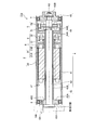
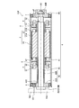
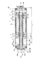
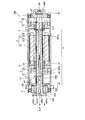
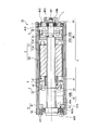
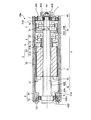
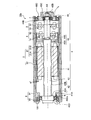
- FIG. 1 is a cross-sectional view illustrating an example of a roller according to the first embodiment.
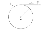
- FIG. 2 is a diagram for explaining the relationship between tension and torque applied to the belt-like transported object in the roller according to the first embodiment.
- FIG. 3 is a diagram illustrating an operation example of the roller according to the first embodiment.
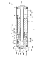
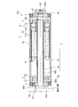
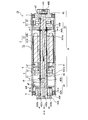
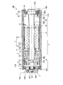
- FIG. 4 is a cross-sectional view illustrating an example of a roller according to the first modification of the first embodiment.
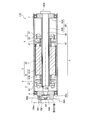
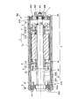
- FIG. 5 is a cross-sectional view illustrating an example of a roller according to the second modification of the first embodiment.
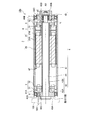
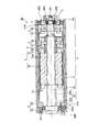
- FIG. 6 is a cross-sectional view illustrating an example of a roller according to the third modification of the first embodiment.
- FIG. 7 is a cross-sectional view illustrating an example of a roller according to the second embodiment.
- FIG. 1 is a cross-sectional view illustrating an example of a roller according to the first embodiment.
- FIG. 2 is a diagram for explaining the relationship between tension and torque applied to the belt-like transported object
- FIG. 8 is a cross-sectional view illustrating an example of a roller according to the first modification of the second embodiment.
- FIG. 9 is a cross-sectional view illustrating an example of a roller according to the second modification of the second embodiment.
- FIG. 10 is a cross-sectional view illustrating an example of a roller according to a third modification of the second embodiment.
- FIG. 11 is a cross-sectional view illustrating an example of a roller according to the third embodiment.
- FIG. 12 is a cross-sectional view illustrating an example of a roller according to a modification of the third embodiment.
- FIG. 13 is a cross-sectional view illustrating an example of a roller according to the fourth embodiment.
- FIG. 14 is a cross-sectional view illustrating an example of a roller according to a modification of the fourth embodiment.
- FIG. 15 is a cross-sectional view illustrating an example of a roller according to the fifth embodiment.
- FIG. 16A is a plan view of the outer ring pressing member in the fifth embodiment when viewed in the direction of arrow A in FIG. 15.
- FIG. 16B is a plan view of the outer ring pressing member in the fifth embodiment when viewed in the direction of arrow B in FIG. 16A.
- FIG. 17A is a diagram illustrating an example of a plan view of the inner ring presser member according to the fifth embodiment when viewed in the direction of arrow C in FIG. 15.
- FIG. 16A is a plan view of the outer ring pressing member in the fifth embodiment when viewed in the direction of arrow A in FIG. 15.
- FIG. 17B is a plan view of the inner ring pressing member in the fifth embodiment when viewed in the direction of arrow D in FIG. 17A.
- FIG. 18 is a cross-sectional view illustrating an example of a roller according to the sixth embodiment.
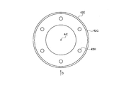
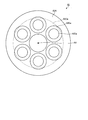
- 19A is a diagram showing an example of a cross-sectional view taken along the line AA shown in FIG. 18 of the torsional rigidity reduced portion.
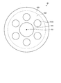
- FIG. 19B is a diagram showing an example different from FIG. 19A of the AA cross-sectional view shown in FIG. 18 of the torsional rigidity reduced portion.
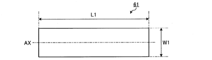
- FIG. 20A is a diagram illustrating an example of a hole portion constituting the torsional rigidity reduced portion.
- FIG. 20B is a diagram illustrating an example different from FIG.
- FIG. 20A of the hole portion constituting the torsional rigidity reduced portion is a diagram illustrating an example different from FIGS. 20A and 20B of the hole portion constituting the torsional rigidity reduced portion.
- FIG. 20D is a diagram illustrating an example different from FIGS. 20A, 20B, and 20C of the hole that constitutes the torsional rigidity reduced portion.
- FIG. 21 is a cross-sectional view illustrating another example of the roller according to the sixth embodiment. 22 is a cross-sectional view taken along the line BB shown in FIG. 21 of the torsional rigidity reduced portion.
- FIG. 23A is a diagram illustrating an example of a slit constituting the torsional rigidity reduced portion.
- FIG. 23B is a diagram illustrating an example different from FIG. 23A of the slits constituting the torsional rigidity reduced portion.
- FIG. 23C is a diagram showing an example different from FIGS. 23A and 23B of the slits constituting the torsional rigidity reduced portion.
- FIG. 24 is a cross-sectional view illustrating another example of the roller according to the sixth embodiment. 25 is a cross-sectional view taken along the line CC of FIG. 24 of the torsional rigidity reduced portion.
- FIG. 26A is a diagram illustrating an example of a thin portion constituting the torsional rigidity reduced portion.
- FIG. 26B is a diagram showing an example different from FIG. 26A of the thin portion constituting the torsional rigidity reduced portion.
- FIG. 26A is a diagram illustrating an example different from FIG. 26A of the thin portion constituting the torsional rigidity reduced portion.
- FIG. 27 is a cross-sectional view illustrating an example of a roller according to Modification 1 of Embodiment 6.
- FIG. 28 is a cross-sectional view illustrating an example of a roller according to Modification 2 of Embodiment 6.
- FIG. 29 is a cross-sectional view illustrating an example of a roller according to Modification 3 of Embodiment 6.
- FIG. 30 is a cross-sectional view illustrating an example of a roller according to the seventh embodiment.
- FIG. 31 is a cross-sectional view illustrating an example of a roller according to Modification 1 of Embodiment 7.
- FIG. 32 is a cross-sectional view illustrating an example of a roller according to Modification 2 of Embodiment 7.
- FIG. 33 is a cross-sectional view illustrating an example of a roller according to Modification 3 of Embodiment 7.
- FIG. 34 is a cross-sectional view illustrating an example of a roller according to the eighth embodiment.
- FIG. 35 is a cross-sectional view illustrating an example of a roller according to the ninth embodiment.
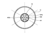
- 36 is a plan view of the penetrating shaft in the roller according to the ninth embodiment when viewed in the direction of arrow A in FIG.
- FIG. 37 is a plan view of the torsion bar in the roller according to the ninth embodiment when viewed in the direction of arrow A in FIG.
- FIG. 38 is a cross-sectional view illustrating an example of a roller according to the tenth embodiment.
- FIG. 39 is a plan view of the through shaft in the roller according to the tenth embodiment when viewed in the direction of arrow A shown in FIG.
- FIG. 40 is a plan view of the torsion bar in the roller according to the tenth embodiment when viewed in the direction of arrow A shown in FIG. 41 is a cross-sectional view of the roller according to the tenth embodiment, taken along line BB shown in FIG.
- FIG. 42 is a cross-sectional view of the roller according to the tenth embodiment, taken along the line CC in FIG.
- FIG. 43 is a cross-sectional view illustrating an example of a roller according to a modification of the tenth embodiment.
- FIG. 44 is a cross-sectional view illustrating an example of a roller according to the eleventh embodiment.
- FIG. 45 is a cross-sectional view taken along the line C′-C ′ shown in FIG. 44 of the roller according to the eleventh embodiment.
- FIG. 46 is a cross-sectional view illustrating an example of a roller according to the twelfth embodiment.
- FIG. 47A is a diagram illustrating a configuration example of a fitting portion between the rotor housing of the roller and the outer cylindrical roller according to the twelfth embodiment.
- FIG. 47B is a diagram illustrating a configuration example different from FIG. 47A of the fitting portion between the rotor housing of the roller and the outer cylinder roller according to the twelfth embodiment.
- FIG. 47C is a diagram showing a configuration example different from FIGS.
- FIG. 47A and 47B of the fitting portion between the rotor housing of the roller and the outer cylinder roller according to the twelfth embodiment are a diagram showing a configuration example different from FIGS. 47A, 47B, and 47C of the fitting portion between the rotor housing of the roller and the outer cylindrical roller according to the twelfth embodiment.
- FIG. 47E is a diagram showing a configuration example different from FIGS. 47A, 47B, 47C, and 47D of the fitting portion between the rotor housing of the roller and the outer cylinder roller according to the twelfth embodiment.
- FIG. 48 is a cross-sectional view illustrating an example of a roller according to Modification 1 of Embodiment 12.
- FIG. 48 is a cross-sectional view illustrating an example of a roller according to Modification 1 of Embodiment 12.
- FIG. 49 is a cross-sectional view illustrating an example of a roller according to the second modification of the twelfth embodiment.
- FIG. 50 is a cross-sectional view illustrating an example of a roller according to Modification 3 of Embodiment 12.
- FIG. 51 is a cross-sectional view illustrating an example of a roller according to Modification 4 of Embodiment 12.
- FIG. 52 is a cross-sectional view illustrating an example of a roller according to Modification 5 of Embodiment 12.
- FIG. 53 is a cross-sectional view illustrating an example of a roller according to Modification 6 of Embodiment 12.
- FIG. 54 is a cross-sectional view illustrating an example of a roller according to Modification 7 of Embodiment 12.
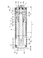
- FIG. 1 is a cross-sectional view illustrating an example of a roller according to the first embodiment.
- the roller 11 is a direct drive motor that directly transmits generated power to an object without using a speed reduction mechanism.
- the roller 11 includes a motor unit 2 that generates power for transporting a belt-shaped transport object, for example, a high-functional film such as a liquid crystal film or an organic EL film used for a flexible substrate or a curved display.
- a rotation detector 3 for detecting the rotation of the motor unit 2, a housing 4 for holding the motor unit 2 and the rotation detector 3, and a torque detector 5 for detecting the torque generated by the roller 11. .
- the motor unit 2, the rotation detector 3, and the torque detector 5 are each electrically connected to a control device (not shown), and the roller 11 is controlled by this control device.
- the motor unit 2 includes a stator 21 and a rotor 22 that can rotate with respect to the stator 21.
- the rotor 22 rotates about the rotation axis AX.
- a direction parallel to the rotation axis AX is also referred to as an “axial direction”.
- the motor unit 2 is an outer rotor type motor.
- the rotor 22 is disposed around the stator 21.
- the rotor 22 is disposed outside the stator 21 with respect to the rotation axis AX.
- the stator 21 has a stator core 21A and a coil 21B supported by the stator core 21A.
- the stator core 21A has a plurality of teeth arranged at equal intervals around the rotation axis AX.
- a plurality of coils 21B are provided.
- Coil 21B is supported by each of a plurality of teeth of stator core 21A.
- the rotor 22 includes a plurality of permanent magnets arranged at equal intervals around the rotation axis AX.
- the stator core 21A of the stator 21 and the rotor 22 face each other via the first gap g1.
- the rotation detector 3 is a resolver including a resolver stator 31 and a resolver rotor 32, and position information including at least one of the rotation speed, the rotation direction, and the rotation angle of the rotor 22 in the motor unit 2. To detect.
- the torque detector 5 is a resolver including a resolver stator 51 and a resolver rotor 52. The torque detector 5 will be described later.
- the housing 4 includes a cylindrical roller housing 41 that rotates together with the rotor 22, a torsion bar 42, a through shaft 43, and a disk member 45.
- the penetrating shaft 43 is provided through the torsion bar 42. One end in the axial direction of the through shaft 43 is fixed to one end in the axial direction of the torsion bar 42, and a fitting portion 43 ⁇ / b> A for positioning the equipment 100 by in-row is provided.
- the penetrating shaft 43 faces the torsion bar 42 via the second gap g2 from the fixing portion with the torsion bar 42 toward the other end in the axial direction.
- the other end of the through shaft 43 in the axial direction passes through the disk member 45 and is fixed to the disk member 45 with a nut 43B.
- the torsion bar 42 is connected to the other end in the axial direction from the disk portion 42 ⁇ / b> A via the second gap g ⁇ b> 2 between the disk portion 42 ⁇ / b> A provided at one end in the axial direction fixed to the through shaft 43 and the through shaft 43. And a cylindrical portion 42 ⁇ / b> B extending in the direction.
- the disk portion 42 ⁇ / b> A of the torsion bar 42 is provided with a screw hole 42 ⁇ / b> C for fixing to the facility 100 with the screw 101 and a mounting surface to the facility 100.
- a stator core 21A of the stator 21 and a resolver stator 31 of the rotation detector 3 are provided on the outer peripheral surface of the cylindrical portion 42B of the torsion bar 42.
- a support member 44 is provided at the other end in the axial direction of the cylindrical portion 42B.
- one axial end where the torsion bar 42 is fixed to the through shaft 43 is also referred to as “a fixed end between the torsion bar 42 and the through shaft 43”.
- the other end in the axial direction of the cylindrical portion 42B is also referred to as “the open end of the torsion bar 42”.
- the support member 44 includes a disc portion 44A fixed to the open end of the torsion bar 42, and a cylindrical portion 44B extending from the outer peripheral portion of the disc portion 44A to the other end side in the axial direction.
- a resolver rotor 52 of the torque detector 5 is provided on the inner peripheral surface of the cylindrical portion 44 ⁇ / b> B of the support member 44, and the resolver stator 51 of the torque detector 5 is disposed on the penetrating shaft 43 at a position facing the resolver rotor 52. Is provided.
- roller housing 41 in the axial direction is supported by the outer peripheral portion of the disk portion 42 ⁇ / b> A of the torsion bar 42 via the first bearing 6, and the other end in the axial direction is the outer periphery of the disk member 45 via the second bearing 7.
- the first bearing 6 has an inner ring supported by the disk portion 42 ⁇ / b> A of the torsion bar 42 and an outer ring supported by the inner peripheral surface of the roller housing 41.
- the second bearing 7 has an inner ring supported by the disk member 45 and an outer ring supported by the inner peripheral surface of the roller housing 41.
- the rotor 22 of the motor unit 2 is provided at a position facing the stator 21 of the motor unit 2, and the resolver of the rotation detector 3 is positioned at a position facing the resolver stator 31 of the rotation detector 3.
- a rotor 32 is provided.
- the rotation detector 3 is arranged on the fixed end side of the torsion bar 42 with respect to the motor unit 2.
- FIG. 2 is a diagram for explaining the relationship between tension and torque applied to the belt-like transported object in the roller according to the first embodiment.
- FIG. 3 is a diagram illustrating an operation example of the roller according to the first embodiment.
- the rigidity with respect to the rotation direction of the through shaft 43 is sufficiently large with respect to the torque generated by the driving force of the motor unit 2, and the rigidity with respect to the rotation direction of the torsion bar 42 is the rotation direction of the through shaft 43. It should be smaller than the rigidity against.
- the rotation detector 3 is a first rotation detector
- the torque detector 5 is a second rotation detector that can detect an angular displacement of, for example, 1 degree or less
- the motor unit 2 is used.
- the angular displacement (small angle ⁇ ) of the open end of the torsion bar 42 when driven is detected.
- the tension F shown in the equation (1) can be obtained. That is, the position information of the motor unit 2 detected by the rotation detector 3 (first rotation detector) and the angle of the open end of the torsion bar 42 detected by the torque detector 5 (second rotation detector).
- tension control for transporting the belt-shaped transported object 200 with appropriate tension is achieved. It becomes possible.
- the second gap g2 is preferably narrow enough not to hinder the torsion of the torsion bar 42 when the motor unit 2 is driven, and more specifically, for example, about 0.05 mm to 0.2 mm. desirable. Further, by providing the second gap g2 between the cylindrical portion 42B of the torsion bar 42 and the through shaft 43, the error range of the first gap g1 interposed between the stator core 21A of the stator 21 and the rotor 22 is increased. .
- the relationship between the first gap g1 and the second gap g2 is g1 ⁇ g2
- the stator core 21A of the stator 21 and the rotor 22 may come into contact with each other when the motor unit 2 is driven. For this reason, it is desirable that the relationship between the first gap g1 and the second gap g2 is g1> g2.
- the shielding plate 8 is provided to prevent the magnetic interference between the rotation detector 3 and the motor unit 2.
- the rotation detector 3 and the motor unit 2 have a magnetic interference between each other. In the case where they are arranged so as not to be affected by the above, the shielding plate 8 may not be provided.
- the support member 44 by configuring the support member 44 with a ferromagnetic member having a magnetic shielding effect, it is possible to prevent magnetic interference between the torque detector 5 and the motor unit 2, and the example shown in FIG. Then, a shielding plate is not provided between the torque detector 5 and the motor unit 2, but when the support member 44 is made of a member such as resin or aluminum, the torque detector 5 and the motor unit 2 A shielding plate may be provided between them to prevent mutual magnetic interference.
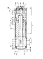
- FIG. 4 is a cross-sectional view illustrating an example of a roller according to the first modification of the first embodiment.
- the rotation detector 3 is disposed between the motor unit 2 and the torque detection unit 5.
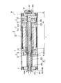
- FIG. 5 is a cross-sectional view illustrating an example of a roller according to the second modification of the first embodiment.
- the rotation detector 3 is provided on the other end side in the axial direction from the torque detector 5.
- the change range of the position information of the motor unit 2 detected by the rotation detector 3 when the motor unit 2 is driven is sufficiently large with respect to the relative twist of the cylindrical portion 42B of the torsion bar 42 with respect to the through shaft 43. For this reason, the influence on the detection accuracy of the rotation detector 3 is small by the position in the axial direction where the rotation detector 3 is provided.
- the twist in the rotational direction position of the resolver stator 31 of the rotation detector 3 with respect to the through shaft 43 when the motor unit 2 is driven is larger than in the example shown in FIG. 1.
- the range of change in the position information of the motor unit 2 detected by the rotation detector 3 when the motor unit 2 is driven is sufficiently large with respect to the relative twist of the cylindrical portion 42B of the torsion bar 42 with respect to the through shaft 43. Since it is large, the influence of the position of the rotation detector 3 on the torsion bar 42 on the detection accuracy of the rotation detector 3 can be ignored.
- the resolver stator 31 of the rotation detector 3 is provided on the penetrating shaft 43 having higher rotational rigidity than the torsion bar 42. For this reason, the detection accuracy of the rotation detector 3 when the motor unit 2 is driven is not affected by the relative twist of the cylindrical portion 42 ⁇ / b> B of the torsion bar 42 with respect to the through shaft 43.
- the position information detected by the rotation detector 3 is obtained even if the resolver stator 31 of the rotation detector 3 is arranged in the cylindrical portion 42B of the torsion bar 42, and the resolver stator 31 of the rotation detector 3 is passed through the shaft. It can be regarded as equivalent to the case where it is arranged at 43. That is, the rotation detector 3 can be regarded as detecting position information of the roller housing 41 with respect to the through shaft 43.
- FIG. 6 is a cross-sectional view illustrating an example of a roller according to the third modification of the first embodiment.
- a fitting portion 45A for positioning by in-row with respect to the equipment 100a is provided on the disk member 45a side.
- the disk member 45a is provided with a screw hole 45B for fixing to the facility 100a with a screw 101 and a mounting surface to the facility 100a.
- the nut 43B can be accessed from the facility 100a side, and maintenance work is facilitated. Further, since the motor unit 2, the rotation detector 3, and the torque detector 5 are arranged close to the equipment 100a side in the axial direction, the position of the center of gravity of the roller 11c in the axial direction is close to the equipment 100a side. The load applied to the connecting portion with 100a can be reduced.
- the rotation detector 3 is the first rotation detector and the torque detector 5 is the second rotation detector that can detect an angular displacement of 1 degree or less, for example. It is the structure which detects the angular displacement (micro angle
- the torque detector 5 may be a strain gauge provided on the torsion bar 42, for example.
- the tension F shown in the equation (1) is obtained. As described above, tension control for transporting the belt-shaped transported object 200 with appropriate tension becomes possible.
- the rollers 11, 11 a, 11 b, and 11 c include the motor unit 2 including the stator 21 and the rotor 22 that is opposed to the radial direction of the stator 21 and rotates relatively, and the rotor 22.
- a cylindrical roller housing 41 that rotates with the cylindrical roller housing 41, a cylindrical torsion bar 42 to which the stator 21 is fixed, and an inner wall of the torsion bar 42 are passed through a gap, and one end of the torsion bar 42 in the axial direction is inserted.
- the first and second bearings 6 and 7 are disposed at positions where the motor section is sandwiched in the axial direction, and the roller housing 41 is rotatably supported, and the rotation of the roller housing 41 is detected.
- the rotation detector 3 first rotation detector
- the relative rotation of the other end in the axial direction of the torsion bar 42 with respect to the through shaft 43 are detected. It has a torque detector 5 (the second rotation detector), the.
- the angular displacement (small angle ⁇ ) of the other end of the motor to output control the motor unit 2 so as to obtain a torque that can achieve a target tension
- the belt-shaped transported object 200 is transported with an appropriate tension. Therefore, the tension control can be performed. This eliminates the need for a tension detection roller, thereby reducing the total number of rollers used in the film transport path.
- FIG. 7 is a cross-sectional view illustrating an example of a roller according to the second embodiment.
- symbol is attached
- the roller 11d in the present embodiment is configured to detect the relative position information of the roller housing 41 with respect to the open end of the torsion bar 42 by the second rotation detector 5.
- the second rotation detector 5 is provided at the open end of the torsion bar 42, and the first rotation detector 3 sandwiches the motor unit 2 with respect to the second rotation detector 5. It is provided on the fixed end side of the torsion bar 42. More specifically, the resolver stator 51 of the second rotation detector 5 is provided at the open end of the torsion bar 42, and the resolver stator 31 of the first rotation detector 3 is fixed to the fixed end of the torsion bar 42 rather than the motor 2. It is provided near.
- the resolver rotor 32 of the first rotation detector 3 is provided at a position facing the resolver stator 31 of the first rotation detector 3 on the inner peripheral surface of the rotor 22, and the resolver rotor 52 of the second rotation detector 5. Is provided at a position facing the resolver stator 51 of the second rotation detector 5 on the inner peripheral surface of the rotor 22.
- the amount of twist in the rotational direction of the torsion bar 42 with respect to the through shaft 43 generated by the reaction force received by the torsion bar 42 when the motor unit 2 is driven is zero at the fixed end of the torsion bar 42, and the torsion bar 42 is opened in the axial direction. It gets bigger as you go to the end. That is, the amount of twist in the rotational direction at the axial position of the torsion bar 42 where the first rotation detector 3 is disposed is the amount of twist in the rotational direction at the open end of the torsion bar 42 where the second rotation detector 5 is disposed. Less than the amount. In other words, the position information detected by the first rotation detector 3 is less affected by the twist in the rotational direction of the torsion bar 42 than the position information detected by the second rotation detector 5.
- the difference between the position information detected by the first rotation detector 3 and the position information detected by the second rotation detector 5 is taken, and this difference is twisted in the rotational direction of the torsion bar 42. Is converted into a torque T as an angular displacement by.
- the tension F shown to (1) Formula of Embodiment 1 can be calculated
- the change range of the position information of the motor unit 2 detected by the rotation detector 3 when the motor unit 2 is driven is a relative twist of the cylindrical portion 42B of the torsion bar 42 with respect to the through shaft 43.
- the influence on the detection accuracy of the first rotation detector 3 is small due to the position in the axial direction where the first rotation detector 3 is provided.
- the difference between the position information detected by the first rotation detector 3 and the position information detected by the second rotation detector 5 is taken, and this difference is angularly displaced due to the twist of the torsion bar 42 in the rotational direction.
- a high-resolution rotation detector equivalent to the torque detector 5 (second rotation detector) in the first embodiment More specifically, it is preferable to have a resolution smaller than 1/100 when the torsion amount of the torsion bar 42 when the maximum torque of the motor unit 2 is generated is 1.
- FIG. 8 is a cross-sectional view illustrating an example of a roller according to the first modification of the second embodiment.
- the first rotation detector 3 is arranged closer to the fixed end of the torsion bar 42 than the example shown in FIG.
- FIG. 9 is a cross-sectional view illustrating an example of a roller according to the second modification of the second embodiment.
- the first rotation detector 3 is provided on the other end side in the axial direction from the second rotation detector 5.
- the change range of the position information of the motor unit 2 detected by the first rotation detector 3 when the motor unit 2 is driven is the cylindrical portion 42B of the torsion bar 42 with respect to the through shaft 43. Large enough for the relative twist of Therefore, it can be regarded as equivalent to the case where the resolver stator 31 of the first rotation detector 3 is disposed on the through shaft 43. That is, the first rotation detector 3 can be regarded as detecting position information of the roller housing 41 with respect to the through shaft 43.
- the twist at the rotational direction position of the resolver stator 31 of the first rotation detector 3 relative to the through shaft 43 when the motor unit 2 is driven is smaller than in the example shown in FIG. 1. That is, the influence on the detection accuracy of the first rotation detector 3 by the twist of the first rotation detector 3 in the rotational direction position of the resolver stator 31 with respect to the through shaft 43 when the motor unit 2 is driven can be reduced.
- the difference between the position information detected by the first rotation detector 3 and the position information detected by the second rotation detector 5 can be made larger than the example shown in FIG.
- the resolver stator 31 of the first rotation detector 3 is provided on the through shaft 43 having a greater rotational rigidity than the torsion bar 42. Therefore, the detection accuracy of the first rotation detector 3 when the motor unit 2 is driven is not affected by the relative twist of the cylindrical portion 42B of the torsion bar 42 with respect to the through shaft 43, and the first rotation.
- the difference between the position information detected by the detector 3 and the position information detected by the second rotation detector 5 can be made larger than the example shown in FIG.
- FIG. 10 is a cross-sectional view illustrating an example of a roller according to a third modification of the second embodiment.
- a fitting portion 45A for positioning by in-row with respect to the equipment 100a is provided on the disk member 45a side.
- the disk member 45a is provided with a screw hole 45B for fixing to the facility 100a with a screw 101 and a mounting surface to the facility 100a.
- the nut 43B can be accessed from the equipment 100a side, and the maintenance work becomes easy. Further, since the motor unit 2, the rotation detector 3 and the torque detector 5 are arranged close to the equipment 100a side in the axial direction, the position of the center of gravity of the roller 11g in the axial direction is close to the equipment 100a side. The load applied to the connecting portion with 100a can be reduced.
- the rollers 11d, 11e, 11f, and 11g include the motor unit 2 including the stator 21 and the rotor 22 that is opposed to the outer side in the radial direction of the stator 21 and relatively rotates, and the rotor 22.
- a cylindrical roller housing 41 that rotates with the cylindrical roller housing 41, a cylindrical torsion bar 42 to which the stator 21 is fixed, and an inner wall of the torsion bar 42 are passed through a gap, and one end of the torsion bar 42 in the axial direction is inserted.
- the first and second bearings 6 and 7 are disposed at positions where the motor section is sandwiched in the axial direction, and the roller housing 41 is rotatably supported, and the rotation of the roller housing 41 is detected.
- a second rotation detector 3 detects a relative rotation of the roller housing 41 with respect to the other end of the torsion bar 42 in the axial direction. It has rolling and the detector 5, a.
- the tension control for transporting the belt-shaped transported object 200 with an appropriate tension by controlling the output of the motor unit 2 so that the target tension can be obtained using the difference from the position information of 2. Is possible. This eliminates the need for a tension detection roller, thereby reducing the total number of rollers used in the film transport path.
- FIG. 11 is a cross-sectional view illustrating an example of a roller according to the third embodiment.
- symbol is attached
- the penetration shaft 43 of the roller 12 is provided so as to penetrate the torsion bar 42 as in the first and second embodiments.
- One end in the axial direction of the through shaft 43 is fixed to one end in the axial direction of the torsion bar 42, and a fitting portion 43 ⁇ / b> A for positioning the equipment 100 by in-row is provided.
- the penetrating shaft 43 faces the torsion bar 42 via the second gap g2 from the fixing portion with the torsion bar 42 toward the other end in the axial direction.
- the other end in the axial direction of the penetrating shaft 43 passes through the disk member 45 and is mechanically connected to the disk member 45 by a nut (adjusting member) 43B via a disc spring 43C that is an elastic member. Has been.
- the penetrating shaft 43, the disk portion 42 ⁇ / b> A of the torsion bar 42, the disk member 45, and the disc spring 43 ⁇ / b> C constitute a preload mechanism that applies preload to the first bearing 6 and the second bearing 7.
- the first bearing 6 is clamped in the axial direction in a state where the corner of the outer ring contacts the step 41A of the roller housing 41 and the corner of the inner ring contacts the step 42D of the disk portion 42A of the torsion bar 42.
- the second bearing 7 is sandwiched in the axial direction with the corner of the outer ring abutting against the step 41B of the roller housing 41 and the corner of the inner ring abutting the step 45C of the disk member 45.
- the nut 43B is tightened via the disc spring 43C, and the disc spring 43C is compressed to L shorter than the natural length, so that preload is applied to both the first bearing 6 and the second bearing 7. it can.
- difference of an axial direction and radial direction is suppressed, and generation
- FIG. 11 has shown the example which has arrange
- FIG. 1 The change range of the position information of the motor unit 2 detected by the rotation detector 3 when the motor unit 2 is driven is sufficiently large with respect to the relative twist of the cylindrical portion 42B of the torsion bar 42 with respect to the through shaft 43.
- the influence on the detection accuracy of the rotation detector 3 by the position in the axial direction where the rotation detector 3 is provided is small.
- the rotation detector 3 may be disposed between the motor unit 2 and the torque detection unit 5 similarly to the roller 11a (FIG.
- the resolver stator 31 of the rotation detector 3 is provided on the penetrating shaft 43 having higher rotational rigidity than the torsion bar 42. For this reason, the detection accuracy of the rotation detector 3 when the motor unit 2 is driven is not affected by the relative twist of the cylindrical portion 42 ⁇ / b> B of the torsion bar 42 with respect to the through shaft 43.
- the position information detected by the rotation detector 3 is obtained even if the resolver stator 31 of the rotation detector 3 is arranged in the cylindrical portion 42B of the torsion bar 42, and the resolver stator 31 of the rotation detector 3 is passed through the shaft. It can be regarded as equivalent to the case where it is arranged at 43. That is, the rotation detector 3 can be regarded as detecting position information of the roller housing 41 with respect to the through shaft 43.
- FIG. 12 is a cross-sectional view illustrating an example of a roller according to a modification of the third embodiment.
- the fitting portion 45A for positioning by the inlay with respect to the equipment 100a is provided on the disk member 45a side. It has been.
- the disk member 45a is provided with a screw hole 45B for fixing to the facility 100a with a screw 101 and a mounting surface to the facility 100a.
- the nut 43B can be accessed from the equipment 100a side by opening the adjustment hole 102 in the equipment 100a. Maintenance work such as preload adjustment becomes easy.
- the motor unit 2, the rotation detector 3, and the torque detector 5 are arranged close to the equipment 100a in the axial direction, the position of the center of gravity of the roller 12a in the axial direction is close to the equipment 100a side. The load applied to the connecting portion with 100a can be reduced.
- the rotation detector 3 is the first rotation detector and the torque detector 5 is the second rotation detector that can detect an angular displacement of 1 degree or less, for example. It is the structure which detects the angular displacement (micro angle
- the torque detector 5 may be a strain gauge provided on the torsion bar 42, for example.
- the tension F shown in the equation (1) is obtained. As described above, tension control for transporting the belt-shaped transported object 200 with appropriate tension becomes possible.
- the rollers 12 and 12 a include the stator 21, the motor unit 2 including the rotor 22 that is disposed to face the outer side in the radial direction of the stator 21 and relatively rotates, and the cylinder that rotates together with the rotor 22. Is inserted through a gap between a cylindrical roller housing 41, a cylindrical torsion bar 42 to which the stator 21 is fixed, and an inner wall of the torsion bar 42, and fixes one end of the torsion bar 42 in the axial direction. At least one of the shaft 43, the first bearing 6 and the second bearing 7, which are disposed at a position sandwiching the motor portion in the axial direction and rotatably support the roller housing 41, and the first bearing 6 and the second bearing 7.
- the preload mechanism is provided at a fixed end of the through shaft 43 and the through shaft 43 of the torsion bar 42, the disk portion 42 ⁇ / b> A in which the inner ring of the first bearing 6 is fixed on the outer periphery, and the other end in the axial direction of the through shaft 43.
- an elastic member that applies a biasing force to the disk member 45 in a direction parallel to the axial direction toward one end of the through shaft 43.
- Disc spring 43C is provided at a fixed end of the through shaft 43 and the through shaft 43 of the torsion bar 42, the disk portion 42 ⁇ / b> A in which the inner ring of the first bearing 6 is fixed on the outer periphery, and the other end in the axial direction of the through shaft 43.
- the rollers 12 and 12a according to the third embodiment are similar to the first and second embodiments in that the rotation detector 3 (first rotation detector) that detects the rotation of the roller housing 41 and the torsion bar for the through shaft 43 are used. And a torque detector 5 (second rotation detector) for detecting the relative rotation of the other end in the axial direction of 42.
- the rotation detector 3 first rotation detector
- the torque detector 5 second rotation detector
- the angular displacement (small angle ⁇ ) of the other end of the motor to output control the motor unit 2 so as to obtain a torque that can achieve a target tension
- the belt-shaped transported object 200 is transported with an appropriate tension. Therefore, the tension control can be performed.
- FIG. 13 is a cross-sectional view illustrating an example of a roller according to the fourth embodiment.
- symbol is attached
- the roller 12b in the present embodiment uses a compression coil spring 43D as an elastic member.
- the first bearing 6 is configured such that the corner of the outer ring contacts the step 41A of the roller housing 41 and the corner of the inner ring contacts the step 42D of the disk portion 42A of the torsion bar 42. Sandwiched in the direction.
- the second bearing 7 is sandwiched in the axial direction with the corner of the outer ring abutting against the step 41B of the roller housing 41 and the corner of the inner ring abutting the step 45C of the disk member 45.
- the nut (adjustment member) 43B is tightened via the compression coil spring 43D, and the compression coil spring 43D is compressed to L ′ shorter than the natural length, whereby the first bearing 6 and the second bearing 7 are compressed. Preload can be applied to both.
- the constant pressure preload state can be maintained even in a high temperature environment or when the difference between the internal temperature and the external temperature of the roller 12b is large compared to the third embodiment using the disc spring as the elastic member. Can be maintained.
- the second rotation detector 5 causes the roller housing 41 to be relative to the open end of the torsion bar 42. The position information is detected.
- the second rotation detector 5 is provided at the open end of the torsion bar 42, similarly to the roller 11 e (FIG. 8) according to the first modification of the second embodiment.
- 3 is provided on the fixed end side of the torsion bar 42 with respect to the second rotation detector 5 with the motor unit 2 interposed therebetween. More specifically, the resolver stator 51 of the second rotation detector 5 is provided at the open end of the torsion bar 42, and the resolver stator 31 of the first rotation detector 3 is fixed to the torsion bar 42 more than the motor unit 2. It is provided near the edge.
- the resolver rotor 32 of the first rotation detector 3 is provided at a position facing the resolver stator 31 of the first rotation detector 3 on the inner peripheral surface of the rotor 22, and the resolver rotor 52 of the second rotation detector 5. Is provided at a position facing the resolver stator 51 of the second rotation detector 5 on the inner peripheral surface of the rotor 22.
- the amount of twist in the rotational direction of the torsion bar 42 with respect to the through shaft 43 generated by the reaction force received by the torsion bar 42 when the motor unit 2 is driven is zero at the fixed end of the torsion bar 42, and the torsion bar 42 is opened in the axial direction. It gets bigger as you go to the end. That is, the amount of twist in the rotational direction at the axial position of the torsion bar 42 where the first rotation detector 3 is disposed is the amount of twist in the rotational direction at the open end of the torsion bar 42 where the second rotation detector 5 is disposed. Less than the amount. In other words, the position information detected by the first rotation detector 3 is less affected by the twist in the rotational direction of the torsion bar 42 than the position information detected by the second rotation detector 5.
- the difference between the position information detected by the first rotation detector 3 and the position information detected by the second rotation detector 5 is taken, and this difference is twisted in the rotational direction of the torsion bar 42. Is converted into a torque T as an angular displacement by.
- the tension F shown to (1) Formula of Embodiment 1 can be calculated
- the change range of the position information of the motor unit 2 detected by the rotation detector 3 when the motor unit 2 is driven is a relative twist of the cylindrical portion 42B of the torsion bar 42 with respect to the through shaft 43.
- the influence on the detection accuracy of the first rotation detector 3 is small due to the position in the axial direction where the first rotation detector 3 is provided.
- the difference between the position information detected by the first rotation detector 3 and the position information detected by the second rotation detector 5 is taken, and this difference is angularly displaced due to the twist of the torsion bar 42 in the rotational direction.
- first rotation detector 3 and the second rotation detector 5 in the fourth embodiment high-resolution rotation equivalent to the torque detector 5 (second rotation detector) in the first and third embodiments. It is preferable to use a detector, and more specifically, it is desirable to have a resolution smaller than 1/100 when the torsion amount of the torsion bar 42 when the maximum torque of the motor unit 2 is generated is 1. .
- the change range of the position information of the motor unit 2 detected by the first rotation detector 3 when the motor unit 2 is driven is the cylinder of the torsion bar 42 with respect to the through shaft 43. It is sufficiently large with respect to the relative twist of the portion 42B. Therefore, it can be regarded as equivalent to the case where the resolver stator 31 of the first rotation detector 3 is disposed on the through shaft 43. That is, the first rotation detector 3 can be regarded as detecting position information of the roller housing 41 with respect to the through shaft 43.
- the resolver stator 31 of the first rotation detector 3 is provided on the penetrating shaft 43 that has higher rotational rigidity than the torsion bar 42.
- the detection accuracy of the first rotation detector 3 when the motor unit 2 is driven is not affected by the relative twist of the cylindrical portion 42 ⁇ / b> B of the torsion bar 42 with respect to the through shaft 43.
- the difference between the position information detected by the first rotation detector 3 and the position information detected by the second rotation detector 5 can be increased.
- FIG. 14 is a cross-sectional view illustrating an example of a roller according to a modification of the fourth embodiment.
- the fitting portion 45A for positioning by the in-row with respect to the equipment 100a is provided on the disk member 45a side. It has been.
- the disk member 45a is provided with a screw hole 45B for fixing to the facility 100a with a screw 101 and a mounting surface to the facility 100a.
- the nut 43 ⁇ / b> B can be accessed from the equipment 100 a side by opening the adjustment hole 102 in the equipment 100 a. Maintenance work such as preload adjustment becomes easy.
- the motor unit 2, the rotation detector 3, and the torque detector 5 are arranged close to the equipment 100a side in the axial direction, the position of the center of gravity of the roller 12c in the axial direction is close to the equipment 100a side. The load applied to the connecting portion with 100a can be reduced.
- the rollers 12b and 12c according to the fourth embodiment use the compression coil spring 43D as an elastic member instead of the disc spring in the third embodiment. This makes it possible to maintain the constant pressure preload state in the high temperature environment or even when the difference between the internal temperature of the rollers 12b and 12c and the external temperature is large compared to the third embodiment using the disc spring as the elastic member. .
- rollers 12b and 12c according to the fourth embodiment are similar to the first, second, and third embodiments in that the first rotation detector 3 that detects the rotation of the roller housing 41 and the other end of the torsion bar 42 in the axial direction. And a second rotation detector 5 for detecting relative rotation of the roller housing 41 with respect to the second rotation detector 5.
- the position information detected by the first rotation detector 3 the position information of the motor section 2 detected by the first rotation detector 3, and the motor section detected by the second rotation detector 5.
- the tension control for transporting the belt-shaped transported object 200 with an appropriate tension by controlling the output of the motor unit 2 so that the target tension can be obtained using the difference from the position information of 2. Is possible.
- FIG. 15 is a cross-sectional view illustrating an example of a roller according to the fifth embodiment.
- symbol is attached
- the roller 12d does not have a disc spring or a compression coil spring that is an elastic member, and uses a back combination bearing as the first bearing 6A.
- the first bearing (back combination bearing) 6A constitutes a preload mechanism.
- the outer ring of the first bearing (back combination bearing) 6A is clamped in the axial direction by having one corner portion in contact with the step 41A of the roller housing 41 and the other corner portion in contact with the outer ring pressing member 41C. Further, the inner ring of the first bearing (rear combination bearing) 6A has one corner portion in contact with the step 42D of the disk portion 42A of the torsion bar 42 and the other corner portion in contact with the inner ring holding member 42E. Sandwiched in the direction.
- the combination bearings such as the back combination bearing and the front combination bearing are set with a preload in a state where the two bearings are combined, and the preload by the elastic member described in the third and fourth embodiments is not necessary.
- the roller 12d with high rotational accuracy can be obtained by using such a combination bearing.
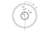
- FIG. 16A is a plan view of the outer ring pressing member in the fifth embodiment when viewed in the direction of arrow A in FIG.
- FIG. 16B is a plan view of the outer ring pressing member in the fifth embodiment when viewed in the direction of arrow B in FIG. 16A.
- 16A and 16B show an example in which four jig holes 41E for holding the outer ring pressing member 41C with a jig (not shown) are arranged in the circumferential direction. The position and number of 41E are not limited to this.
- the outer ring pressing member 41C is an annular member in which an outer thread is provided on the outer peripheral surface and a convex portion 41D that comes into contact with the outer ring of the first bearing (back combination bearing) 6A is provided.
- the protrusion provided on the jig (not shown) is fitted into the jig hole 41E, and the outer screw is turned into the inner screw provided on the roller housing 41, so that the convex portion 41D becomes the first bearing (rear combination)
- the outer ring of the first bearing (back combination bearing) 6A is clamped in the axial direction.
- FIG. 17A is a diagram illustrating an example of a plan view of the inner ring pressing member in the fifth embodiment when viewed in the direction of arrow C in FIG. 15.
- FIG. 17B is a plan view of the inner ring pressing member in the fifth embodiment when viewed in the direction of arrow D in FIG. 17A.
- 17A and 17B show an example in which six screw holes 42H for fixing the inner ring pressing member 42E to the disk portion 42A of the torsion bar 42 with the screws 42F are arranged in six circumferential directions. The position and number of the holes 42H are not limited to this.
- the inner ring pressing member 42E is an annular member provided with a step 42G and a screw hole 42H that are in contact with the inner ring of the first bearing (back combination bearing) 6A, and the inner ring pressing member 42E.
- the torsion bar 42 are fixed with a plurality of screws 42F (here, the number of screw holes 42H: 6), so that the step 42G comes into contact with the inner ring of the first bearing (rear combination bearing) 6A, and the first The inner ring of the bearing (back combination bearing) 6A is held in the axial direction.
- a backup bearing such as a deep groove ball bearing may be used as the second bearing 7, for example.
- the first bearing 6A as the back combination bearing, rattling in the axial direction and the radial direction is suppressed, so that the allowable range for the axial position of the second bearing 7 is increased. For this reason, it is not always necessary to sandwich the step 41B of the roller housing 41 and the step 45C of the disk member 45 in the axial direction.
- the first bearing is a back combination bearing
- the second bearing may be a back combination bearing, and both the first bearing and the second bearing may be used.
- the configuration may be a back combination bearing.
- the combination bearing used as the preload mechanism is not limited to the rear combination bearing, and may be a front combination bearing, for example.
- the back combination bearing it is possible to increase the rigidity against the bending moment acting in the axial direction. That is, it is possible to obtain high rigidity with respect to the moment load applied in the direction orthogonal to the rotation axis AX with respect to the central portion in the axial direction of the roller housing.
- the roller 12d according to the fifth embodiment uses a combination bearing that constitutes at least one of the first bearing and the second bearing as the preload mechanism. With this configuration, it is not necessary to provide a preload mechanism using an elastic member as in the third and fourth embodiments, and a configuration with excellent maintainability can be obtained. Moreover, the roller 12d with high rotational accuracy can be obtained by using a combination bearing.
- FIG. 18 is a cross-sectional view illustrating an example of a roller according to the sixth embodiment.
- symbol is attached
- roller 13 As shown in FIG. 18, a part of one end side in the axial direction of the torsion bar 42, more specifically, a fixed end of the torsion bar 42 and the through shaft 43, and rotation detection are detected.
- a rigidity reduction portion 60 is provided.
- the torsion bar 42 is on the one end side in the axial direction (the fixed end side between the torsion bar 42 and the through shaft 43) and on the other end side in the axial direction (the open end side of the torsion bar 42).
- the torsional rigidity lowering portion 60 having a lower rigidity with respect to the twisting direction (rotating direction with the rotation axis AX as the central axis) is used.
- FIG. 19A is a diagram showing an example of a cross-sectional view taken along the line AA shown in FIG. 18 of the torsional rigidity reduced portion.
- FIG. 19B is a diagram showing an example different from FIG. 19A of the AA cross-sectional view shown in FIG. 18 of the torsional rigidity reduced portion.
- FIG. 20A is a diagram illustrating an example of a hole portion constituting the torsional rigidity reduced portion.
- FIG. 20B is a diagram illustrating an example different from FIG. 20A of the hole portion constituting the torsional rigidity reduced portion.
- FIG. 20C is a diagram illustrating an example different from FIGS. 20A and 20B of the hole portion constituting the torsional rigidity reduced portion.
- FIG. 20A is a diagram showing an example of a cross-sectional view taken along the line AA shown in FIG. 18 of the torsional rigidity reduced portion.
- FIG. 19B is a diagram showing an example different from FIG. 19A of the AA cross-
- 20D is a diagram illustrating an example different from FIGS. 20A, 20B, and 20C of the hole that constitutes the torsional rigidity reduced portion.
- 19A, 19B, 20A, 20B, 20C, and 20D show an example in which the torsional rigidity reduced portion 60 is configured by providing a plurality of hole portions 61 that reach the inner wall surface from the outer wall surface of the cylindrical portion 42B of the torsion bar 42.
- FIG. 19A an example is shown in which the hole 61 shown in FIG. 20A is disposed opposite to the rotation axis AX.
- 20A shows an example in which the shape of the hole 61 is a rounded rectangle that is long in the axial direction of the axial length L1 and the circumferential width W1, the axis of the hole 61
- the semicircular portions at both ends in the direction have an action of dispersing stress applied to both ends of the hole 61 when the twist in the rotational direction acts on the torsional rigidity reduced portion 60.
- the shape of the hole 61 is a rounded rectangular shape that is long in the axial direction.
- the torsional rigidity lowering portion 60 having a lower rigidity with respect to the torsional direction (rotational direction with the rotation axis AX as the central axis) than the open end side portion is configured.
- 20A and 20B show an example in which the long axis direction (longitudinal direction) of the hole 61 coincides with the rotation axis AX (axial direction), but as shown in FIG. 20C, the long axis of the hole 61
- the direction (longitudinal direction) may be configured to be inclined at a predetermined angle ⁇ with respect to the rotation axis AX (axial direction).
- the aspect of the hole part 61 may be an aspect other than the rectangular shape shown in FIGS. 20A and 20C, which is long in the axial direction, or a rectangle shown in FIG. 20B, for example, as shown in FIG. It may be composed of a plurality of circular holes 62.
- the present invention is not limited by the form of the hole 61.
- FIG. 19A a configuration is shown in which holes 61 of the same shape having the same length L1 in the axial direction and the width W1 in the circumferential direction are arranged to face each other across the rotation axis AX.
- a configuration may be adopted in which three holes 61 having the same shape and having the same length L1 in the axial direction and the width W1 in the circumferential direction are equally arranged in the circumferential direction.
- FIG. 19B a configuration in which three holes 61 having the same shape and the same length L1 in the axial direction and the width W1 in the circumferential direction are equally arranged in the circumferential direction is shown.
- the present invention is not limited to this, and a configuration in which a plurality of four or more hole portions 61 having the same axial length L1 and circumferential width W1 are equally arranged in the circumferential direction may be employed.
- FIG. 21 is a cross-sectional view showing another example of the roller according to the sixth embodiment.
- a roller 13a shown in FIG. 21 has a configuration having a torsional rigidity reduced portion 60a instead of the torsional rigidity reduced portion 60 in the example shown in FIG.
- FIG. 22 is a view showing a cross-sectional view taken along the line BB of FIG. 21 of the torsional rigidity reduced portion.
- FIG. 23A is a diagram illustrating an example of a slit constituting the torsional rigidity reduced portion.
- FIG. 23B is a diagram illustrating an example different from FIG. 23A of the slits constituting the torsional rigidity reduced portion.
- FIG. 23C is a diagram showing an example different from FIGS. 23A and 23B of the slits constituting the torsional rigidity reduced portion. In the example shown in FIGS.
- the torsional rigidity reduced portion 60a is configured by providing a plurality of slits 61a that reach the inner wall surface from the outer wall surface of the cylindrical portion 42B of the torsion bar 42 is shown.
- FIG. 22 shows an example in which the slits 61a shown in FIG. 23A are evenly arranged in the circumferential direction.
- the slit 61a only needs to have a substantial circumferential width W2 of 0 or more (W2 ⁇ 0).
- W2 ⁇ 0 a substantial circumferential width
- FIG. 23A an example in which circular holes 62a are provided at both ends of the slit 61a having the axial length L2 and the circumferential width W2, the hole 62a has a reduced torsional rigidity.
- the twist in the rotation direction acts on the portion 60a, it has an action of dispersing stress applied to both ends of the slit 61a.
- FIG. 23A an example in which the twist in the rotation direction acts on the portion 60a, it has an action of dispersing stress applied to both ends of the slit 61a.
- a configuration may be adopted in which the circular holes 62a are not provided at both ends of the slit 61a, but when the rotational torsion acts on the torsional rigidity reduced portion 60a, the slit 61a In order to disperse the stress applied to both ends, it is more preferable to provide circular holes 62a at both ends of the slit 61a as shown in FIG. 23A.
- the torsion bar 42 A torsional rigidity reduced portion 60a having a lower rigidity with respect to the torsional direction (rotational direction with the rotation axis AX as the central axis) than the open end side portion is configured.
- the slit 61a coincides with the rotation axis AX (axial direction). However, as shown in FIG. 23C, the slit 61a corresponds to the rotation axis AX (axial direction).
- a configuration inclined by a predetermined angle ⁇ may be used.
- the aspect of the slit 61a may be an aspect other than FIGS. 23A, 23B, and 23C, and the present invention is not limited by the aspect of the slit 61a.
- a configuration is shown in which eight slits 61a having the same shape with the same length L2 in the axial direction and the width W2 in the circumferential direction are equally arranged in the circumferential direction.
- the slit 61a having the same shape having the same length L2 in the axial direction and the width W2 in the circumferential direction may be configured to be opposed to each other with the rotation axis AX interposed therebetween.
- a configuration in which three or more slits 61a having the same shape with the same L2 and circumferential width W2 are equally arranged in the circumferential direction may be employed.
- FIG. 24 is a cross-sectional view showing another example of the roller according to the sixth embodiment.
- the roller 13b shown in FIG. 24 shows a configuration having a torsional rigidity reduced portion 60b instead of the torsional rigidity reduced portion 60 in the example shown in FIG.
- FIG. 25 is a cross-sectional view taken along the line CC of FIG. 24 showing the torsional rigidity reduced portion.
- FIG. 26A is a diagram illustrating an example of a thin portion constituting the torsional rigidity reduced portion.
- FIG. 26B is a diagram showing an example different from FIG. 26A of the thin portion constituting the torsional rigidity reduced portion.
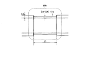
- 25, 26A, and 26B show an example in which the torsional rigidity reduced portion 60b is configured by a thin-walled portion 61b in which the thickness in the radial direction of the torsion bar 42 is thinner at the center than at both ends in the axial direction.
- the thin portion 61b having the axial length L3 shown in FIG. 26A is provided evenly in the circumferential direction.
- the radial thickness D3 of the cylindrical portion 44B in the central portion in the axial direction of the thin portion 61b is larger in the radial direction of the cylindrical portion 44B outside the both ends in the axial direction of the thin portion 61b.
- An example in which the thickness is smaller than the thickness D4 is shown (D3 ⁇ D4).
- the example in which the thin wall portion 61b is inclined in a concave curve shape from both axial end portions toward the central portion is shown.
- the radial thickness D3 may be uniform within the range of the length L3 in the axial direction, but when the twist in the rotational direction acts on the torsional rigidity reduced portion 60b, the thin portion
- the thin wall portion 61b is inclined in a concave curve shape from both end portions in the axial direction toward the central portion, as shown in FIG. 26A.
- the twist direction (the rotation axis AX) is greater than the portion of the torsion bar 42 on the open end side.
- the torsional rigidity reduced portion 60b having a low rigidity with respect to the rotation direction with respect to the central axis is configured.
- the aspect of the thin part 61b may be an aspect other than FIGS. 26A and 26B, and the present invention is not limited by the aspect of the thin part 61b.
- the rollers 13, 13 a, and 13 b are arranged between the fixed end of the torsion bar 42 and the through shaft 43 and the rotation detector 3, on the other end side in the axial direction of the torsion bar 42, That is, the torsional rigidity lowering portions 60, 60a, and 60b having lower rigidity in the torsional direction (rotational direction with the rotation axis AX as the central axis) than the portion on the open end side of the torsion bar 42 are provided.
- the detection accuracy of the angular displacement (small angle ⁇ ) of the open end of the torsion bar 42 detected by the torque detector 5 (second rotation detector). can be improved.
- the axial length of the torsional rigidity reduced portions 60, 60a, 60b that is, the axial length L1 of the hole 61 in the torsional rigidity reduced portion 60, and the axial length of the slit 61a in the torsional rigidity reduced portion 60a.
- the axial length L3 of the thin portion 61b in the torsional rigidity reduced portion 60b depends on the axial length (full length) of the rollers 13, 13a, 13b, the number of rotations, and other usage conditions. What is necessary is just to determine suitably.
- the hole 61 in the torsional rigidity reduced portion 60 may be used in combination, or the slit 61a in the torsional rigidity reduced part 60a and the thin part 61b in the torsional rigidity reduced part 60b. You may use together.
- FIG. 27 is a cross-sectional view illustrating an example of a roller according to Modification 1 of Embodiment 6.
- the rotation detector 3 is disposed between the motor unit 2 and the torque detection unit 5
- the torsional rigidity reduction unit 60 is fixed to the torsion bar 42 and the through shaft 43, the motor unit 2 and Between.
- FIG. 28 is a cross-sectional view illustrating an example of a roller according to Modification 2 of Embodiment 6.
- the rotation detector 3 is provided on the other end side in the axial direction from the torque detector 5, and the torsional rigidity reduced portion 60 is fixed to the torsion bar 42 and the through shaft 43, the motor unit 2, Between.
- the change range of the position information of the motor unit 2 detected by the rotation detector 3 when the motor unit 2 is driven is sufficiently large with respect to the relative twist of the cylindrical portion 42B of the torsion bar 42 with respect to the through shaft 43. For this reason, the influence on the detection accuracy of the rotation detector 3 is small by the position in the axial direction where the rotation detector 3 is provided.
- the twist in the rotational direction position of the resolver stator 31 of the rotation detector 3 relative to the through shaft 43 when the motor unit 2 is driven is larger than in the example shown in FIG.
- the change range of the position information of the motor unit 2 detected by the rotation detector 3 when the motor unit 2 is driven is based on the relative twist of the cylindrical portion 42B of the torsion bar 42 with respect to the through shaft 43.
- the influence of the position of the rotation detector 3 on the torsion bar 42 on the detection accuracy of the rotation detector 3 can be ignored.
- the resolver stator 31 of the rotation detector 3 is provided on the through shaft 43 having a greater rotational rigidity than the torsion bar 42. For this reason, the detection accuracy of the rotation detector 3 when the motor unit 2 is driven is not affected by the relative twist of the cylindrical portion 42 ⁇ / b> B of the torsion bar 42 with respect to the through shaft 43.
- the position information detected by the rotation detector 3 is obtained even if the resolver stator 31 of the rotation detector 3 is arranged in the cylindrical portion 42B of the torsion bar 42, and the resolver stator 31 of the rotation detector 3 is passed through the shaft. It can be regarded as equivalent to the case where it is arranged at 43. That is, the rotation detector 3 can be regarded as detecting position information of the roller housing 41 with respect to the through shaft 43.
- the rollers 13c and 13d shown in FIGS. 27 and 28 are arranged between the fixed end of the torsion bar 42 and the penetrating shaft 43 and the motor unit 2, and the other end side in the axial direction of the torsion bar 42, that is, the torsion bar 42.
- a torsional rigidity reducing portion 60 having a lower rigidity in the torsional direction (rotational direction with the rotation axis AX as the central axis) than the open end side portion.
- FIG. 29 is a cross-sectional view illustrating an example of a roller according to Modification 3 of Embodiment 6.
- a fitting portion 45A for positioning by in-row with respect to the equipment 100a is provided on the disk member 45a side.
- the disk member 45a is provided with a screw hole 45B for fixing to the facility 100a with a screw 101 and a mounting surface to the facility 100a.
- the nut 43B can be accessed from the facility 100a side, and maintenance work such as preload adjustment becomes easy.
- the motor unit 2, the rotation detector 3, and the torque detector 5 are arranged close to the equipment 100a in the axial direction, the position of the center of gravity of the roller 13e in the axial direction is close to the equipment 100a side. The load applied to the connecting portion with 100a can be reduced.
- the torsional rigidity lowering portion 60 having a lower rigidity with respect to the torsional direction (rotational direction with the rotation axis AX as the central axis) than the portion on the open end side of the torsion bar 42 is provided.
- the rotation detector 3 is the first rotation detector and the torque detector 5 is the second rotation detector that can detect an angular displacement of 1 degree or less, for example. It is the structure which detects the angular displacement (micro angle
- the torque detector 5 may be a strain gauge provided on the torsion bar 42, for example.
- the tension F shown in the equation (1) is obtained. As described above, tension control for transporting the belt-shaped transported object 200 with appropriate tension becomes possible.
- a torsional rigidity reduced portion 60 a is provided as shown in FIG. 21.
- a torsional rigidity reduced portion 60b may be provided.
- the rollers 13, 13 a, 13 b, 13 c, 13 d, and 13 e are the motor unit 2 including the stator 21 and the rotor 22 that is opposed to the outer side in the radial direction of the stator 21 and relatively rotates. And a cylindrical roller housing 41 that rotates together with the rotor 22, a cylindrical torsion bar 42 to which the stator 21 is fixed, and an inner wall of the torsion bar 42.
- a torque detector 5 (the second rotation detector) the detecting the rotation.
- the torsion bar 42 has a torsional rigidity reduced portion 60, 60a, 60b having a lower rigidity in the torsional direction than the other end side in the axial direction on one end side in the axial direction.
- the angular displacement (small angle ⁇ ) of the other end of the motor to output control the motor unit 2 so as to obtain a torque that can achieve a target tension
- the belt-shaped transported object 200 is transported with an appropriate tension. Therefore, the tension control can be performed. This eliminates the need for a tension detection roller, thereby reducing the total number of rollers used in the film transport path.
- the torsional rigidity is reduced at the one end side in the axial direction of the torsion bar 42, and the rigidity in the torsional direction (rotational direction with the rotation axis AX as the central axis) is lower than that at the other end side in the axial direction of the torsion bar 42.
- the torsional rigidity lowering portion 60 has lower rigidity in the torsional direction (rotational direction with the rotation axis AX as the central axis) than the other end side in the axial direction of the torsion bar 42, that is, the open end side part of the torsion bar 42. , 60a, 60b, the detection accuracy of the angular displacement (small angle ⁇ ) of the open end of the torsion bar 42 detected by the torque detector 5 (second rotation detector) can be improved.
- the torsion bar 42 and the through shaft 43 are fixed. Rigidity in the torsion direction (rotation direction about the rotation axis AX) as compared to the other end side in the axial direction of the torsion bar 42, that is, the open end side portion of the torsion bar 42 between the end and the motor unit 2
- the detection accuracy of the angular displacement (small angle ⁇ ) of the open end of the torsion bar 42 detected by the torque detector 5 (second rotation detector) is increased. Can be improved.
- the rotation detector 3 first rotation detector
- the torque detector 5 second rotation detector
- the torsion bar 42 and the through shaft 43 Between the fixed end and the motor unit 2, the twist direction (rotation direction with the rotation axis AX as the central axis) relative to the other end side in the axial direction of the torsion bar 42, that is, the open end side portion of the torsion bar 42.
- the torsional rigidity reduction portions 60, 60a, 60b having low rigidity, the detection accuracy of the angular displacement (small angle ⁇ ) of the open end of the torsion bar 42 detected by the torque detector 5 (second rotation detector). Can be improved.
- FIG. 30 is a cross-sectional view illustrating an example of a roller according to the seventh embodiment.
- symbol is attached
- the roller 13f in the present embodiment is configured to detect relative position information of the roller housing 41 with respect to the open end of the torsion bar 42 by the second rotation detector 5.
- the second rotation detector 5 is provided at the open end of the torsion bar 42, and the first rotation detector 3 sandwiches the motor unit 2 with respect to the second rotation detector 5. It is provided on the fixed end side of the torsion bar 42. More specifically, the resolver stator 51 of the second rotation detector 5 is provided at the open end of the torsion bar 42, and the resolver stator 31 of the first rotation detector 3 is fixed to the fixed end of the torsion bar 42 rather than the motor 2. It is provided near.
- the resolver rotor 32 of the first rotation detector 3 is provided at a position facing the resolver stator 31 of the first rotation detector 3 on the inner peripheral surface of the rotor 22, and the resolver rotor 52 of the second rotation detector 5. Is provided at a position facing the resolver stator 51 of the second rotation detector 5 on the inner peripheral surface of the rotor 22.
- a torsional rigidity lowering portion 60 having a lower rigidity with respect to the torsional direction (rotational direction about the rotation axis AX) than the other end side in the axial direction of the torsion bar 42, that is, the open end side of the torsion bar 42 is provided. ing.
- the amount of twist in the rotational direction of the torsion bar 42 with respect to the through shaft 43 generated by the reaction force received by the torsion bar 42 when the motor unit 2 is driven is zero at the fixed end of the torsion bar 42, and the torsion bar 42 is opened in the axial direction. It gets bigger as you go to the end. That is, the amount of twist in the rotational direction at the axial position of the torsion bar 42 where the first rotation detector 3 is disposed is the amount of twist in the rotational direction at the open end of the torsion bar 42 where the second rotation detector 5 is disposed. Less than the amount. In other words, the position information detected by the first rotation detector 3 is less affected by the twist in the rotational direction of the torsion bar 42 than the position information detected by the second rotation detector 5.
- the difference between the position information detected by the first rotation detector 3 and the position information detected by the second rotation detector 5 is taken, and this difference is twisted in the rotational direction of the torsion bar 42. Is converted into torque T as an angular displacement (small angle ⁇ ) due to.
- the tension F shown to (1) Formula of Embodiment 1 can be calculated
- the change range of the position information of the motor unit 2 detected by the rotation detector 3 when the motor unit 2 is driven is a relative twist of the cylindrical portion 42B of the torsion bar 42 with respect to the through shaft 43.
- the influence on the detection accuracy of the first rotation detector 3 is small due to the position in the axial direction where the first rotation detector 3 is provided.
- the difference between the position information detected by the first rotation detector 3 and the position information detected by the second rotation detector 5 is taken, and this difference is angularly displaced due to the twist of the torsion bar 42 in the rotational direction.
- a high-resolution rotation detector equivalent to the torque detector 5 (second rotation detector) in the sixth embodiment More specifically, it is preferable to have a resolution smaller than 1/100 when the torsion amount of the torsion bar 42 when the maximum torque of the motor unit 2 is generated is 1.
- the roller 13f shown in FIG. 30 is disposed between the fixed end of the torsion bar 42 and the through shaft 43 and the rotation detector 3, and the other end side in the axial direction of the torsion bar 42, that is, the torsion bar.
- a torsional rigidity reduction portion 60 having a lower rigidity with respect to the torsional direction (rotational direction with the rotation axis AX as the central axis) than the open end side portion of 42 is provided.
- FIG. 31 is a cross-sectional view illustrating an example of a roller according to Modification 1 of Embodiment 7.
- the first rotation detector 3 is disposed closer to the fixed end of the torsion bar 42 than in the example shown in FIG. 30, and the torsional rigidity reduced portion 60 is connected to the motor portion 2 and the first rotation. It is provided between the detector 3.
- FIG. 32 is a cross-sectional view illustrating an example of a roller according to Modification 2 of Embodiment 7.
- the first rotation detector 3 is provided on the other end side in the axial direction with respect to the second rotation detector 5, and the torsional rigidity reduced portion 60 is fixed to the torsion bar 42 and the through shaft 43. It is provided between the end and the motor unit 2.
- the change range of the position information of the motor unit 2 detected by the first rotation detector 3 when the motor unit 2 is driven is the cylindrical portion 42B of the torsion bar 42 with respect to the through shaft 43. Large enough for the relative twist of Therefore, it can be regarded as equivalent to the case where the resolver stator 31 of the first rotation detector 3 is disposed on the through shaft 43. That is, the first rotation detector 3 can be regarded as detecting position information of the roller housing 41 with respect to the through shaft 43.
- the twist in the rotational direction position of the resolver stator 31 of the first rotation detector 3 relative to the through shaft 43 when the motor unit 2 is driven is more than in the example shown in FIG. 1. Get smaller. That is, the influence on the detection accuracy of the first rotation detector 3 by the twist of the first rotation detector 3 in the rotational direction position of the resolver stator 31 with respect to the through shaft 43 when the motor unit 2 is driven can be reduced.
- the difference between the position information detected by the first rotation detector 3 and the position information detected by the second rotation detector 5 can be made larger than the example shown in FIG.
- roller 13g shown in FIG. 31 is located between the motor unit 2 and the first rotation detector 3 in the axial direction on the other end side of the torsion bar 42, that is, on the open end side portion of the torsion bar 42.
- a torsional rigidity lowering portion 60 having a low rigidity with respect to the torsional direction (the rotational direction with the rotation axis AX as the central axis) is provided.
- the resolver stator 31 of the first rotation detector 3 is provided on the through shaft 43 having a greater rotational rigidity than the torsion bar 42. Therefore, the detection accuracy of the first rotation detector 3 when the motor unit 2 is driven is not affected by the relative twist of the cylindrical portion 42B of the torsion bar 42 with respect to the through shaft 43, and the first rotation.
- the difference between the position information detected by the detector 3 and the position information detected by the second rotation detector 5 can be made larger than the example shown in FIG.
- roller 13h shown in FIG. 32 is disposed between the fixed end of the torsion bar 42 and the through shaft 43 and the motor unit 2 on the other end side in the axial direction of the torsion bar 42, that is, on the open end side of the torsion bar 42.
- a torsional rigidity reducing portion 60 having a lower rigidity in the torsional direction (rotational direction with the rotation axis AX as the central axis) than the portion is provided.
- FIG. 33 is a cross-sectional view illustrating an example of a roller according to Modification 3 of Embodiment 7.
- a fitting portion 45A for positioning by the in-row with respect to the equipment 100a is provided on the disk member 45a side.
- the disk member 45a is provided with a screw hole 45B for fixing to the facility 100a with a screw 101 and a mounting surface to the facility 100a.
- the nut 43B can be accessed from the facility 100a side, and the maintenance work is facilitated.
- the motor unit 2, the rotation detector 3, and the torque detector 5 are arranged close to the equipment 100a side in the axial direction, the position of the center of gravity of the roller 13i in the axial direction is close to the equipment 100a side. The load applied to the connecting portion with 100a can be reduced.
- a torsional rigidity lowering portion 60 having a lower rigidity in the torsional direction (rotational direction with the rotation axis AX as the central axis) is provided on the side, that is, on the open end side of the torsion bar 42.
- the torsional rigidity reduced portion 60 is provided in the example shown in FIGS. 30, 31, 32, and 33.
- the lowering portion 60a may be provided, or the torsional rigidity lowering portion 60b may be provided as shown in FIG.
- the rollers 13f, 13g, 13h, and 13i include the motor unit 2 including the stator 21 and the rotor 22 that is opposed to the outer side in the radial direction of the stator 21 and relatively rotates, and the rotor 22.
- a cylindrical roller housing 41 that rotates with the cylindrical roller housing 41, a cylindrical torsion bar 42 to which the stator 21 is fixed, and an inner wall of the torsion bar 42 are passed through a gap, and one end of the torsion bar 42 in the axial direction is inserted.
- the first and second bearings 6 and 7 that are disposed at positions that sandwich the motor unit 2 in the axial direction and rotatably support the roller housing 41, and the rotation of the roller housing 41 are detected.
- a first rotation detector 3 that detects the relative rotation of the roller housing 41 with respect to the other axial end of the torsion bar 42.
- a rotation detector 5 and a.
- the torsion bar 42 has a torsional rigidity reduced portion 60, 60a, 60b having a lower rigidity in the torsional direction than the other end side in the axial direction on one end side in the axial direction.
- the tension control for transporting the belt-shaped transported object 200 with an appropriate tension by controlling the output of the motor unit 2 so that the target tension can be obtained using the difference from the position information of 2. Is possible. This eliminates the need for a tension detection roller, thereby reducing the total number of rollers used in the film transport path.
- the torsional rigidity is reduced at the one end side in the axial direction of the torsion bar 42, and the rigidity in the torsional direction (rotational direction with the rotation axis AX as the central axis) is lower than that at the other end side in the axial direction of the torsion bar 42.
- the rotation detector 3 (first rotation detector) is provided on one end side in the axial direction from the motor unit 2, the fixed end of the torsion bar 42 and the through shaft 43 and the rotation detector 3 (first 1 to the other end side in the axial direction of the torsion bar 42, that is, the opening end side portion of the torsion bar 42, with respect to the torsional direction (rotation direction about the rotation axis AX).
- the torsional rigidity reduction portions 60, 60a, 60b having low rigidity
- the position information detected by the rotation detector 3 (first rotation detector) and the torque detector 5 (second rotation detector) are used. It is possible to improve the accuracy of detection of the difference from the detected position information, that is, the angular displacement (small angle ⁇ ) due to the twist in the rotational direction of the torsion bar 42.
- the torsional rigidity lowering portion 60 has lower rigidity in the torsional direction (rotational direction with the rotation axis AX as the central axis) than the other end side in the axial direction of the torsion bar 42, that is, the open end side part of the torsion bar 42.
- 60a, 60b the difference between the position information detected by the rotation detector 3 (first rotation detector) and the position information detected by the torque detector 5 (second rotation detector). That is, it is possible to improve the detection accuracy of the angular displacement (the minute angle ⁇ ) due to the twist of the torsion bar 42 in the rotational direction.
- the disc spring 43C is used as an elastic member that applies preload to the first bearing 6 and the second bearing 7
- a compression coil spring is used instead of the disc spring 43C.
- the constant pressure preload can be achieved even in a high temperature environment or when the difference between the internal temperature and the external temperature of the roller 13i is large compared to the sixth and seventh embodiments using the disc spring 43C as the elastic member. It becomes possible to maintain the state.
- FIG. 34 is a cross-sectional view illustrating an example of a roller according to the eighth embodiment.
- symbol is attached
- a pipe line 43 ⁇ / b> Ca constituting a cooling flow path for allowing the refrigerant to flow inside the through shaft 43 is provided. It has been.
- the range in which the cooling flow path is provided includes at least the axial range in which the motor part 2 is provided in the cylindrical part 42B of the torsion bar 42.
- the conduit 43 ⁇ / b> Ca is provided in communication with the refrigerant inlet 43 ⁇ / b> Da and the outlet 43 ⁇ / b> E provided at the end of the through shaft 43, and is turned back near the open end of the torsion bar 42.
- the pipe line 43 ⁇ / b> Ca constituting the cooling channel includes the axial position where the stator 21 of the motor unit 2 is provided in the cylindrical part 42 ⁇ / b> B of the torsion bar 42, and extends in the axial direction.
- a refrigerant injection pipe (not shown) is connected to the injection port 43Da.
- a refrigerant discharge pipe (not shown) is connected to the discharge port 43E.
- the injection pipe may be screwed into and connected to an internal screw provided on the inner periphery of the injection port 43Da.
- the discharge pipe may be screwed into and connected to the inner screw provided on the inner periphery of the discharge port 43E.
- the present invention is not limited by the connection method between the injection tube and the injection port 43Da and the connection method between the discharge tube and the discharge port 43E.
- the roller 14 includes the stator 21 and the motor unit 2 including the rotor 22 that is disposed opposite to the outer side in the radial direction of the stator 21 and relatively rotates, and the cylindrical portion that rotates together with the rotor 22.
- a through shaft 43 that passes through a gap between the roller housing 41, a cylindrical torsion bar 42 to which the stator 21 is fixed, and an inner wall of the torsion bar 42, and fixes one end of the torsion bar 42 in the axial direction.
- a cooling flow path for flowing is provided.
- the cooling path is provided including at least the axial range in which the motor unit 2 is provided.
- the cooling flow path includes a pipe line 43 ⁇ / b> Ca provided in the through shaft 43.
- FIG. 35 is a cross-sectional view illustrating an example of a roller according to the ninth embodiment.
- symbol is attached
- the second gap g2 between the torsion bar 42 and the through shaft 43 is used as a cooling flow path in addition to the pipe line 43Ca provided in the through shaft 43.
- FIG. 36 is a plan view of the penetrating shaft in the roller according to the ninth embodiment when viewed in the direction of arrow A in FIG.
- a plurality of refrigerant inlets 43 ⁇ / b> Da and a refrigerant outlet 43 ⁇ / b> E are provided at the end of the through shaft 43.
- the example shown in FIG. 36 shows an example in which the discharge port 43E is provided around the rotation axis AX, and six injection ports 43Da are arranged around the discharge port 43E.
- the position and the number of the inlet 43Da and the outlet 43E are not limited to this.
- connection method between the refrigerant injection pipe (not shown) and the injection port 43Da and the connection method between the refrigerant discharge pipe (not shown) and the discharge port 43E are, for example,
- the injection tube may be screwed and connected to the inner screw provided on the inner periphery of the injection port 43Da, and the discharge tube may be connected to the inner screw provided on the inner periphery of the discharge port 43E.
- the present invention is not limited by the connection method between the injection tube and the injection port 43Da and the connection method between the discharge tube and the discharge port 43E.
- FIG. 37 is a plan view of the torsion bar in the roller according to the ninth embodiment when viewed in the direction of arrow A in FIG.
- the disk portion 42 ⁇ / b> A of the torsion bar 42 has a communication passage 42 ⁇ / b> Da that communicates with a storage portion 42 ⁇ / b> Ca, which will be described later, corresponding to the axial position of the inlet 43 ⁇ / b> Da provided at the end of the through shaft 43. Is provided.
- a groove 42Ea is provided around the communication path 42Da.
- an O-ring 42Fa as a seal member is attached to the groove 42Ea.
- the pipe line 43Ca is provided to extend in the axial direction from the fixed end of the torsion bar 42 toward the open end. That is, the pipe line 43 ⁇ / b> Ca constituting the cooling channel includes the axial position where the stator 21 of the motor unit 2 is provided in the cylindrical part 42 ⁇ / b> B of the torsion bar 42, and extends in the axial direction.
- the pipe line 43Ca communicates with a discharge port 43E provided at the end of the through shaft 43 on the fixed end side of the torsion bar 42. Further, the duct 43Ca is provided in communication with the second gap g2 on the open end side of the torsion bar 42.
- the through shaft 43 is provided with a groove 43F in the circumferential direction near the open end of the torsion bar 42, and an O-ring 43G as a seal member is attached to the groove 43F.
- the diameter of the through shaft 43 is smaller than the open end of the torsion bar 42 in the range from the mounting position of the O-ring 43G to the fixed end of the torsion bar 42.
- the second gap g2 is increased and a refrigerant flow path is formed. That is, the second gap g2 constituting the cooling flow path includes the axial position where the stator 21 of the motor unit 2 is provided in the cylindrical portion 42B of the torsion bar 42, and extends in the axial direction.
- the disc part 42A of the torsion bar 42 is provided with a refrigerant storage part 42Ca communicating with the second gap g2.
- the reservoir 42Ca and the inlet 43Da provided at the end of the through shaft 43 communicate with each other through a communication path 42Da provided in the disk portion 42A of the torsion bar 42.
- the second gap g2 is used as a cooling channel. For this reason, heat can be efficiently absorbed from the cylindrical portion 42B of the torsion bar 42 with which the stator core 21A of the stator 21 constituting the motor portion 2 contacts. Thereby, the cooling effect of the motor part 2 can be heightened more than Embodiment 1, and the suppression effect of the temperature rise by the heat_generation
- the roller 14a according to the ninth embodiment has a configuration in which the second gap g2 between the torsion bar 42 and the through shaft 43 is used as a cooling flow path in addition to the conduit 43Ca provided in the through shaft 43. It is said.
- the cooling effect of the motor unit 2 can be enhanced compared to the first embodiment in which only the pipe line 43Ca provided in the through shaft 43 is used as the cooling channel, and the motor unit 2 when the motor unit 2 is driven can be enhanced.
- the effect of suppressing temperature rise due to heat generation can be enhanced.
- FIG. 38 is a cross-sectional view illustrating an example of a roller according to the tenth embodiment.
- symbol is attached
- the roller 15 causes the air between the torsion bar 42 and the roller housing 41 to flow from the space on one end side in the axial direction of the motor unit 2 to the space on the other end side, and is generated in the motor unit 2.
- An endothermic path for absorbing the generated heat and an exhaust heat path for exhausting the air that has absorbed the heat generated by the motor unit 2 in the endothermic path are provided.
- the roller 15 according to the present embodiment is provided with a first disk part (disk part) 42I in the heat absorption path.
- the first disk portion 42I is provided on the fixed end side of the torsion bar 42.
- the outer diameter r2 of the first disk part 42I is larger than the outer diameter r1 of the cylindrical part 42B of the torsion bar 42 (r1 ⁇ r2).
- a third gap g ⁇ b> 3 is provided between the outer peripheral surface of the first disk portion 42 ⁇ / b> I and the inner peripheral surface of the roller housing 41.
- the motor part 2 is provided between the first disk part 42I and the flow opening 42Ha provided on the open end side of the torsion bar 42.
- the first disk portion 42I may be integrally formed with the torsion bar 42 or may be a member different from the torsion bar 42.
- FIG. 39 is a plan view of the penetrating shaft in the roller according to the tenth embodiment when viewed in the direction of arrow A shown in FIG.
- a plurality of intake ports 43 ⁇ / b> Db and exhaust ports 43 ⁇ / b> Ea are provided at the end of the through shaft 43.
- an exhaust port 43Ea is provided around the rotation axis AX, and six intake ports 43Db are arranged equally around the exhaust port 43Ea.
- a suction pump (not shown) is connected to the exhaust port 43Ea, and the suction pump is operated to exhaust the internal air. Note that the positions and number of the intake ports 43Db and the exhaust ports 43Ea are not limited thereto.
- the suction pipe of the suction pump may be screwed into and connected to the inner screw provided on the inner periphery of the exhaust port 43Ea.
- the present invention is not limited by the method of connecting the suction pump and the exhaust port 43Ea.
- FIG. 40 is a plan view of the torsion bar in the roller according to the tenth embodiment when viewed in the direction of arrow A shown in FIG.
- the torsion bar 42 is provided with a through hole 42K through which the through shaft 43 is inserted.
- the disk portion 42A of the torsion bar 42 is provided with an intake passage 42Cb, which will be described later, corresponding to the axial position of the intake port 43Db provided at the end of the through shaft 43.
- the six intake paths 42Cb and the intake ports 43Db are equally arranged in the circumferential direction.
- the number of the intake paths 42Cb and the intake ports 43Db is not limited to this.
- the configuration may be such that the four intake passages 42Cb and the intake ports 43Db are evenly arranged, or the configuration in which two, three, five or more intake passages 42Cb and the intake ports 43Db are equally arranged. It may be.
- the exhaust passage 43Cb extends in the axial direction from the fixed end of the torsion bar 42 and the through shaft 43 toward the open end. That is, the exhaust passage 43 ⁇ / b> Cb constituting the exhaust heat path includes an axial position where the stator 21 of the motor unit 2 is provided in the cylindrical portion 42 ⁇ / b> B of the torsion bar 42, and extends in the axial direction.
- the exhaust passage 43 ⁇ / b> Cb communicates with an exhaust port 43 ⁇ / b> Ea provided at the end of the through shaft 43 on the fixed end side between the torsion bar 42 and the through shaft 43.
- An intake passage 42 ⁇ / b> Cb is provided in the disk portion 42 ⁇ / b> A of the torsion bar 42.
- FIG. 41 is a cross-sectional view of the roller according to the tenth embodiment, taken along line BB shown in FIG. As described above, the third gap g3 is provided between the outer peripheral surface of the first disk portion 42I and the inner peripheral surface of the roller housing 41.
- FIG. 42 is a cross-sectional view taken along the line CC of FIG.
- the torsion bar 42 is provided with a plurality of flow openings 42Ha communicating with the exhaust passage 43Cb provided in the through shaft 43 on the open end side of the torsion bar 42.
- a configuration is shown in which six flow ports 42Ha are equally arranged in the circumferential direction.
- the number of flow ports 42Ha is not limited to this, and four flow ports 42Ha. May be configured to be evenly arranged, or may be a configuration in which two, three, five, or more through holes 42Ha are equally arranged.
- the heat absorption path includes the intake port 43Db, the intake path 42Cb, and the third gap g3. Further, the exhaust heat path is configured to include a through-flow port 42Ha, an exhaust path 43Cb, and an exhaust port 43Ea.
- the air supplied to the motor unit 2 is sucked and exhausted from the exhaust port 43Ea through the flow port 42Ha provided in the torsion bar 42 and the exhaust path 43Cb provided in the through shaft 43.
- the unevenness of the air pressure inside the roller housing 41 can be suppressed by uniformly arranging the plurality of flow openings 42Ha in the circumferential direction.
- the heat generated in the motor unit 2 when the motor unit 2 is driven can be uniformly absorbed over the entire circumference in the circumferential direction, and the temperature rise of the roller 15 due to the heat generated by the motor unit 2 is suppressed. be able to.
- the shielding plate 8 for preventing magnetic interference between the rotation detector 3 and the motor unit 2 is provided.
- the rotation detector 3 and the motor unit 2 have magnetic interference between each other. In the case where they are arranged so as not to be affected by the above, the shielding plate 8 may not be provided.
- the support member 44 by configuring the support member 44 with a ferromagnetic member having a magnetic shielding effect, it is possible to prevent magnetic interference between the torque detector 5 and the motor unit 2, and an example shown in FIG. Then, a shielding plate is not provided between the torque detector 5 and the motor unit 2, but when the support member 44 is made of a member such as resin or aluminum, the torque detector 5 and the motor unit 2 A shielding plate may be provided between them to prevent mutual magnetic interference.
- the rotation detector 3 is arranged on the fixed end side of the torsion bar 42 and the through shaft 43 with respect to the motor unit 2, but the rotation detector 3 rotates when the motor unit 2 is driven.
- the change range of the position information of the motor unit 2 detected by the detector 3 is sufficiently large with respect to the relative twist of the cylindrical portion 42B of the torsion bar 42 with respect to the through shaft 43, and the axial direction in which the rotation detector 3 is provided.
- the influence of the position on the detection accuracy of the rotation detector 3 is small. For this reason, for example, the rotation detector 3 may be disposed between the motor unit 2 and the torque detection unit 5.
- the twist in the rotational direction position of the resolver stator 31 of the rotation detector 3 with respect to the through shaft 43 when the motor unit 2 is driven is larger than the example shown in FIG. 38. Since the change range of the position information of the motor unit 2 detected by the rotation detector 3 when driven is sufficiently large with respect to the relative twist of the cylindrical portion 42B of the torsion bar 42 with respect to the through shaft 43, the rotation detector The influence of the position on the torsion bar 42 on the detection accuracy of the rotation detector 3 can be ignored.
- the rotation detector 3 may be arranged on the other end side in the axial direction from the torque detector 5.
- the resolver stator 31 of the rotation detector 3 is provided on the penetrating shaft 43 having higher rotational rigidity than the torsion bar 42. For this reason, the detection accuracy of the rotation detector 3 when the motor unit 2 is driven is not affected by the relative twist of the cylindrical portion 42 ⁇ / b> B of the torsion bar 42 with respect to the through shaft 43.
- the position information detected by the rotation detector 3 is obtained even if the resolver stator 31 of the rotation detector 3 is arranged in the cylindrical portion 42B of the torsion bar 42, and the resolver stator 31 of the rotation detector 3 is passed through the shaft. It can be regarded as equivalent to the case where it is arranged at 43. That is, the rotation detector 3 can be regarded as detecting position information of the roller housing 41 with respect to the through shaft 43.
- the rotation detector 3 is the first rotation detector and the torque detector 5 is the second rotation detector that can detect an angular displacement of 1 degree or less, for example. It is the structure which detects the angular displacement (micro angle
- the torque detector 5 may be a strain gauge provided on the torsion bar 42, for example.
- the tension F shown in the equation (1) is obtained. As described above, tension control for transporting the belt-shaped transported object 200 with appropriate tension becomes possible.
- FIG. 43 is a cross-sectional view illustrating an example of a roller according to a modification of the tenth embodiment. Note that the same components as those in FIG. 38 described above are denoted by the same reference numerals, and redundant description is omitted.
- the configuration of the heat absorption path and the exhaust heat path is the same as the example shown in FIG.
- the second rotation detector 5 detects the relative position information of the roller housing 41 with respect to the open end of the torsion bar 42. In the example shown in FIG.
- the second rotation detector 5 is provided at the open end of the torsion bar 42, and the first rotation detector 3 sandwiches the motor unit 2 with respect to the second rotation detector 5. It is provided on the fixed end side of the torsion bar 42. More specifically, the resolver stator 51 of the second rotation detector 5 is provided at the open end of the torsion bar 42, and the resolver stator 31 of the first rotation detector 3 is fixed to the fixed end of the torsion bar 42 rather than the motor 2. It is provided near.
- the resolver rotor 32 of the first rotation detector 3 is provided at a position facing the resolver stator 31 of the first rotation detector 3 on the inner peripheral surface of the rotor 22, and the resolver rotor 52 of the second rotation detector 5. Is provided at a position facing the resolver stator 51 of the second rotation detector 5 on the inner peripheral surface of the rotor 22.
- the amount of twist in the rotational direction of the torsion bar 42 with respect to the through shaft 43 generated by the reaction force received by the torsion bar 42 when the motor unit 2 is driven is zero at the fixed end of the torsion bar 42, and the torsion bar 42 is opened in the axial direction. It gets bigger as you go to the end. That is, the amount of twist in the rotational direction at the axial position of the torsion bar 42 where the first rotation detector 3 is disposed is the amount of twist in the rotational direction at the open end of the torsion bar 42 where the second rotation detector 5 is disposed. Less than the amount. In other words, the position information detected by the first rotation detector 3 is less affected by the twist in the rotational direction of the torsion bar 42 than the position information detected by the second rotation detector 5.
- the difference between the position information detected by the first rotation detector 3 and the position information detected by the second rotation detector 5 is taken, and this difference is taken as the rotation of the torsion bar 42. It is converted into torque T as an angular displacement due to a twist in the direction.
- the tension F shown to (1) Formula of Embodiment 1 can be calculated
- the change range of the position information of the motor unit 2 detected by the rotation detector 3 when the motor unit 2 is driven is that of the cylindrical portion 42 ⁇ / b> B of the torsion bar 42 with respect to the through shaft 43. It has been described that it is sufficiently large with respect to the relative twist, and the influence on the detection accuracy of the first rotation detector 3 by the position in the axial direction where the first rotation detector 3 is provided is small.
- the difference between the position information detected by the first rotation detector 3 and the position information detected by the second rotation detector 5 is taken, and this difference is calculated by the torsion bar 42. This is a configuration intended to be converted into torque T as an angular displacement due to a twist in the rotational direction.
- a high-resolution rotation detector equivalent to the torque detector 5 (second rotation detector) in the first embodiment More specifically, it is preferable to have a resolution smaller than 1/100 when the torsion amount of the torsion bar 42 when the maximum torque of the motor unit 2 is generated is 1.
- the change range of the position information of the motor unit 2 detected by the first rotation detector 3 when the motor unit 2 is driven is relative to the cylindrical portion 42 ⁇ / b> B of the torsion bar 42 with respect to the through shaft 43.
- the resolver stator 31 of the first rotation detector 3 is disposed on the through shaft 43. That is, the first rotation detector 3 can be regarded as detecting position information of the roller housing 41 with respect to the through shaft 43.
- the resolver stator 31 of the first rotation detector 3 is provided on the penetrating shaft 43 that has higher rotational rigidity than the torsion bar 42. For this reason, the detection accuracy of the first rotation detector 3 when the motor unit 2 is driven is not affected by the relative twist of the cylindrical portion 42 ⁇ / b> B of the torsion bar 42 with respect to the through shaft 43. For this reason, the difference between the position information detected by the first rotation detector 3 and the position information detected by the second rotation detector 5 can be increased.
- the rollers 15 and 15a include the stator 21 and the motor unit 2 including the rotor 22 that is disposed opposite to the outer side in the radial direction of the stator 21 via the first gap g1 and relatively rotates.
- a cylindrical roller housing 41 that rotates together with the rotor 22, a cylindrical torsion bar 42 to which the stator 21 is fixed, and an inner wall of the torsion bar 42 pass through a second gap g 2, and the torsion bar 42 A through shaft 43 that fixes one end in the axial direction, and a first bearing 6 and a second bearing 7 that are disposed in a position sandwiching the motor unit 2 in the axial direction and rotatably support the roller housing 41 are provided. is doing.
- an endothermic path that absorbs heat generated in the motor unit 2 by allowing the air between the torsion bar 42 and the roller housing 41 to flow from the space on the one end side in the axial direction of the motor unit 2 to the space on the other end side.
- the first disc portion 42I having a larger outer diameter than the torsion bar 42 is provided in the heat absorption path, and the third gap g3 is provided between the outer peripheral surface of the first disc portion 42I and the inner peripheral surface of the roller housing 41. Is provided.
- the heat generated in the motor unit 2 when the motor unit 2 is driven can be uniformly absorbed over the entire circumference in the heat absorption path, and the temperature rise due to the heat generated by the motor unit 2 can be increased. Can be suppressed. Thereby, while the film quality deterioration in a film conveying apparatus is suppressed, appropriate tension control is attained.
- the first disk portion 42I is provided on the fixed end side between the torsion bar 42 and the through shaft 43. Thereby, air can be uniformly supplied to the motor part 2 in the heat absorption path in the circumferential direction, and temperature rise due to heat generation of the motor part 2 can be suppressed.
- the heat absorption path includes an intake path 42Cb provided in the torsion bar 42.
- a plurality of intake passages 42Cb are provided so as to be evenly arranged in the circumferential direction.
- the through shaft 43 is provided with an intake port 43Db that communicates with the intake passage 42Cb.
- rollers 15 and 15a are provided with an exhaust heat path for exhausting air that has absorbed heat generated by the motor unit 2 in the endothermic path.
- the exhaust heat path includes an exhaust path 43 ⁇ / b> Cb provided in the through shaft 43.
- the through shaft 43 is provided with an exhaust port 43Ea communicating with the exhaust path 43Cb.
- the air flowing from the intake passage 42Cb passes through the third gap g3 to the motor unit. 2 flows into the space inside the roller housing 41 provided with 2. That is, in the present embodiment, the third gap g3 provided uniformly over the entire circumference in the circumferential direction between the inner circumferential surface of the roller housing 41 and the first disc portion 42I is uniform over the entire circumference in the circumferential direction. The air flows in and is sucked and exhausted from the exhaust passage 43 ⁇ / b> Cb provided in the through shaft 43.
- the heat generated in the motor unit 2 when the motor unit 2 is driven can be uniformly discharged over the entire circumference of the roller housing 41, and the motor unit when the motor unit 2 is driven Since the temperature rise due to the heat generation of 2 can be suppressed, deterioration of the quality of the belt-shaped transported object 200 (film in the film transport apparatus) is suppressed, and appropriate tension control is possible.
- the uneven distribution of the air pressure inside the roller housing 41 can be suppressed by arranging the plurality of flow openings 42Ha uniformly in the circumferential direction.
- FIG. 44 is a cross-sectional view illustrating an example of a roller according to the eleventh embodiment.
- symbol is attached
- the roller 15b according to the present embodiment is provided with a second disk part (disk part) 42J in the heat absorption path in addition to the first disk part (disk part) 42I.
- the second disk portion 42J is provided on the open end side of the torsion bar 42.
- the outer diameter r2 ′ of the second disk portion 42J is larger than the outer diameter r1 of the cylindrical portion 42B of the torsion bar 42 (r1 ⁇ r2 ′), and the outer peripheral surface of the second disk portion 42J and the inner peripheral surface of the roller housing 41 are A fourth gap g4 is provided therebetween.
- the motor part 2 is provided between the first disk part 42I and the second disk part 42J.
- the second disk portion 42J may be integrally formed with the torsion bar 42, or may be a member different from the torsion bar 42, like the first disk portion 42I.
- the motor unit 2 includes a first disk part 42I provided on the fixed end side of the torsion bar 42 and a second disk part 42J provided on the open end side of the torsion bar 42. It is provided in the space between.
- FIG. 45 is a cross-sectional view taken along the line C′-C ′ shown in FIG. 44 of the roller according to the eleventh embodiment.
- the fourth gap g4 is provided between the outer peripheral surface of the second disk portion 42J and the inner peripheral surface of the roller housing 41.
- the heat absorption path includes the intake port 43Db, the intake path 42Cb, the third gap g3, and the fourth gap g4.
- the exhaust heat path is configured to include a through-flow port 42Ha, an exhaust path 43Cb, and an exhaust port 43Ea.
- the air in the space between the first disk part 42I and the second disk part 42J flows through the fourth gap g4, the flow opening 42Ha provided in the torsion bar 42, and the exhaust path 43Cb provided in the through shaft 43.
- the air is sucked and exhausted from the exhaust port 43Ea.
- the fourth gap g4 provided uniformly over the entire circumference in the circumferential direction between the inner circumferential surface of the roller housing 41 and the second disk portion 42J is uniform over the entire circumference in the circumferential direction. Air is sucked and exhausted.
- the heat generated in the motor unit 2 provided in the space between the first disk part 42I and the second disk part 42J can be uniformly absorbed and exhausted over the entire circumference in the circumferential direction, and more efficiently.
- the temperature rise of the roller 15b due to the heat generated by the motor unit 2 when the motor unit 2 is driven can be suppressed.
- the roller 15b according to the eleventh embodiment includes the second disk part 42J having an outer diameter larger than that of the torsion bar 42 on the open end side of the torsion bar 42 in addition to the first disk part (disk part) 42I.
- the fourth gap g4 is provided between the outer peripheral surface of the first disk portion 42I and the inner peripheral surface of the roller housing 41.
- the heat generated in the motor unit 2 provided in the space between the first disk part 42I and the second disk part 42J can be uniformly absorbed and exhausted over the entire circumference in the circumferential direction. Since the temperature rise of the roller 15b due to the heat generated by the motor unit 2 when the motor unit 2 is driven more efficiently than 1 can be suppressed, the deterioration of the quality of the belt-shaped transported object 200 (film in the film transport apparatus) is further suppressed. In addition, more appropriate tension control is possible.
- FIG. 46 is a cross-sectional view illustrating an example of a roller according to the twelfth embodiment.
- symbol is attached
- a cylindrical outer cylinder roller 9 is provided along the outer peripheral surface of the roller housing 41.
- the example which provided the outer cylinder roller 9 with respect to the structure shown in FIG. 1 of Embodiment 1 is shown.
- the installation surface with the equipment is a surface on the fixed end side of the torsion bar 42 and the through shaft 43.
- the outer cylinder roller 9 is provided in contact with the cylindrical portion 91 provided along the outer peripheral surface of the roller housing 41 and the fixed end side of the torsion bar 42 and the through shaft 43 of the roller housing 41.
- the screw 101 is screwed in the axial direction into the screw hole 43Dc, so that the roller housing 41 and the disk portion 92 of the outer cylindrical roller 9 are fixed.
- the configuration of the fitting surface between the roller housing 41 and the cylindrical portion 91 of the outer cylinder roller 9 will be described later.
- the rotor 22 of the motor unit 2 is provided at a position facing the stator 21 of the motor unit 2, and the resolver of the rotation detector 3 is positioned at a position facing the resolver stator 31 of the rotation detector 3.
- a rotor 32 is provided.
- the rotation detector 3 is arranged on the fixed end side between the torsion bar 42 and the through shaft 43 with respect to the motor unit 2.
- FIG. 47A is a diagram illustrating a configuration example of a fitting portion between the rotor housing of the roller and the outer cylinder roller according to the twelfth embodiment.
- FIG. 47B is a diagram illustrating a configuration example different from FIG. 47A of the fitting portion between the rotor housing of the roller and the outer cylinder roller according to the twelfth embodiment.
- FIG. 47C is a diagram showing a configuration example different from FIGS. 47A and 47B of the fitting portion between the rotor housing of the roller and the outer cylinder roller according to the twelfth embodiment.
- FIG. 47D is a diagram showing a configuration example different from FIGS.
- FIG. 47E is a diagram showing a configuration example different from FIGS. 47A, 47B, 47C, and 47D of the fitting portion between the rotor housing of the roller and the outer cylinder roller according to the twelfth embodiment.
- the cylindrical outer cylinder roller 9 is provided along the outer peripheral surface of the roller housing 41.
- the outer cylinder roller 9 is detachably attached to the roller housing 41 and rotates together with the rotor 22.
- the roller 16 according to the present embodiment can be replaced with the outer cylinder roller 9 according to the type of the belt-shaped transported object by providing the outer cylinder roller 9 that can be attached to and detached from the roller housing 41. Further, when wear of the contact surface with the belt-shaped transported object, damage to the structure, or the like occurs, it is possible to cope with the problem by replacing the outer cylinder roller 9, and the roller 16 having high maintainability can be obtained.
- the fitting surface of the roller housing 41 and the cylindrical portion 91 of the outer cylindrical roller 9 has a small diameter toward the fixed end of the torsion bar 42 and the through shaft 43, for example, as shown in FIG. 47A.
- the structure which exhibits a taper shape may be sufficient.
- the fitting surface of the roller housing 41 and the cylindrical portion 91 of the outer cylindrical roller 9 has, for example, at least a partial section (section B in the example shown in FIG. 47B) in the axial direction as shown in FIG. 47B.
- burr 42 and the penetration shaft 43 may be sufficient.
- the diameter r1 of the fitting surface of the roller housing 41 and the cylindrical portion 91 of the outer cylindrical roller 9 in the section A on the fixed end side between the torsion bar 42 and the through shaft 43 is determined by the opening of the torsion bar 42.
- the torsion bar 42 and the through shaft 43 are smaller than the diameter r2 of the fitting surface between the roller housing 41 and the cylindrical portion 91 of the outer cylindrical roller 9 in the end section C.
- the taper shape which becomes a small diameter toward the fixed end is shown, the section which shows the taper shape which becomes a small diameter toward the fixed end between the torsion bar 42 and the through shaft 43 penetrates the torsion bar 42 and the through hole.
- the section A on the fixed end side with the shaft 43 may be used, or the section C on the open end side of the torsion bar 42 may be used.
- the fitting surface between the roller housing 41 and the cylindrical portion 91 of the outer cylindrical roller 9 is, for example, as shown in FIG. 47C, a stepped portion 41a provided at a predetermined position in the axial direction of the outer peripheral surface of the roller housing 41.
- the step part 91a provided in the predetermined position of the axial direction of the internal peripheral surface of the cylindrical part 91 of the outer cylinder roller 9 may be the structure which fits in an axial direction.
- the diameter r3 of the fitting surface of the roller housing 41 and the cylindrical portion 91 of the outer cylindrical roller 9 in the section D on the fixed end side between the torsion bar 42 and the penetrating shaft 43 is the opening of the torsion bar 42.
- An example is shown in which the diameter r4 of the fitting surface between the roller housing 41 and the cylindrical portion 91 of the outer cylindrical roller 9 in the end section E is smaller. That is, as shown in FIG. 47C, the diameter r3 of a partial section in the axial direction of the fitting surface between the roller housing 41 and the cylindrical portion 91 of the outer cylindrical roller 9 (section D in the example shown in FIG. 47C)
- the configuration may be different from the diameter r4 of the section (section E in the example shown in FIG. 47C).
- the fitting surface between the roller housing 41 and the cylindrical portion 91 of the outer cylindrical roller 9 is, for example, as shown in FIG. 47D, a stepped portion 41a1 provided at a predetermined position in the axial direction of the outer peripheral surface of the roller housing 41.
- a stepped portion 91 a 1 provided at a predetermined position in the axial direction of the inner peripheral surface of the cylindrical portion 91 of the outer cylindrical roller 9 is fitted in the axial direction, and is provided at a predetermined position in the axial direction of the outer peripheral surface of the roller housing 41.
- the stepped portion 41a2 and the stepped portion 91a2 provided at a predetermined position in the axial direction on the inner peripheral surface of the cylindrical portion 91 of the outer cylindrical roller 9 may be fitted in the axial direction.
- the diameter r3 of the fitting surface of the roller housing 41 and the cylindrical portion 91 of the outer cylindrical roller 9 in the section F on the fixed end side between the torsion bar 42 and the through shaft 43, and the opening of the torsion bar 42 The diameter r3 of the fitting surface of the roller housing 41 and the cylindrical portion 91 of the outer cylinder roller 9 in the end section H is equal, and in the section G between the section F and the section H, the roller housing 41 and the outer cylinder roller 9 shows an example in which the diameter r4 of the fitting surface with the cylindrical portion 91 is larger than the diameter r3 of the fitting surface between the roller housing 41 and the cylindrical portion 91 of the outer cylindrical roller 9 in the sections F and H. Yes.
- the diameter r4 of the partial section in the axial direction of the fitting surface of the roller housing 41 and the cylindrical portion 91 of the outer cylindrical roller 9 (section G in the example shown in FIG. 47D) It is larger than the diameter r3 of the section (section F and section H in the example shown in FIG. 47D).
- the step portion 41a3 provided at a predetermined position in the axial direction of the outer peripheral surface of the roller housing 41 and the predetermined position in the axial direction of the inner peripheral surface of the cylindrical portion 91 of the outer cylindrical roller 9 are provided.
- the stepped portion 91a3 fits in the axial direction, and the stepped portion 41a4 provided at a predetermined position in the axial direction of the outer peripheral surface of the roller housing 41 and the predetermined axial direction of the inner peripheral surface of the cylindrical portion 91 of the outer cylindrical roller 9
- the diameter r3 of the mating surface is equal to the diameter r3 of the mating surface of the roller housing 41 and the cylindrical portion 91 of the outer cylindrical roller 9 in the section H on the open end side of the torsion bar 42.
- the diameter r5 of the fitting surface between the roller housing 41 and the cylindrical portion 91 of the outer cylindrical roller 9 is the same as that of the roller housing 41 and the cylindrical portion 91 of the outer cylindrical roller 9 in the sections F and H.
- the fitting surface is smaller than the diameter r3. That is, in the example shown in FIG.
- the diameter r5 of the partial section in the axial direction of the fitting surface between the roller housing 41 and the cylindrical portion 91 of the outer cylindrical roller 9 (section G in the example shown in FIG. 47E) It is smaller than the diameter r3 of the section (section F and section H in the example shown in FIG. 47E).
- FIGS. 47D and 47E a partial section in the axial direction of the fitting surface between the roller housing 41 and the cylindrical portion 91 of the outer cylindrical roller 9 (section G in the examples shown in FIGS. 47D and 47E).
- the diameters r4 and r5 may be different from the diameter r3 of other sections (section F and section H in the examples shown in FIGS. 47D and 47E).
- FIG. 48 is a cross-sectional view illustrating an example of a roller according to Modification 1 of Embodiment 12.
- the example which provided the outer cylinder roller 9 with respect to the structure shown in FIG. 4 of Embodiment 1 is shown. That is, in the roller 16 a shown in FIG. 48, the rotation detector 3 is disposed between the motor unit 2 and the torque detection unit 5.
- FIG. 49 is a cross-sectional view illustrating an example of a roller according to the second modification of the twelfth embodiment.
- the example which provided the outer cylinder roller 9 with respect to the structure shown in FIG. 5 of Embodiment 1 is shown. That is, in the roller 16b shown in FIG. 49, the rotation detector 3 is provided on the other end side in the axial direction from the torque detector 5.
- FIG. 50 is a cross-sectional view illustrating an example of a roller according to Modification 3 of Embodiment 12.
- the example which provided the outer cylinder roller 9 with respect to the structure shown in FIG. 6 of Embodiment 1 is shown.
- the attachment surface with the facility is the surface on the open end side of the torsion bar 42.
- the disk member 45a is provided with a screw hole 45B for fixing to the equipment with a screw.
- the nut 43B can be accessed from the facility side, and maintenance work is facilitated.
- the motor unit 2, the rotation detector 3, and the torque detector 5 are arranged close to the equipment side in the axial direction, so that the position of the center of gravity of the roller 16c in the axial direction is close to the equipment side, The load applied to the connecting portion can be reduced.
- FIG. 51 is a cross-sectional view illustrating an example of a roller according to Modification 4 of Embodiment 12.
- the example which provided the outer cylinder roller 9 with respect to the structure shown in FIG. 7 of Embodiment 2 is shown. That is, in the roller 16 d shown in FIG. 51, the second rotation detector 5 is provided at the open end of the torsion bar 42, and the first rotation detector 3 is connected to the motor unit 2 with respect to the second rotation detector 5. Is provided on the fixed end side of the torsion bar 42 and the through shaft 43.
- the resolver stator 51 of the second rotation detector 5 is provided at the open end of the torsion bar 42, and the resolver stator 31 of the first rotation detector 3 is connected to the torsion bar 42 and the through shaft rather than the motor 2. 43 near the fixed end.
- the resolver rotor 32 of the first rotation detector 3 is provided at a position facing the resolver stator 31 of the first rotation detector 3 on the inner peripheral surface of the rotor 22, and the resolver rotor 52 of the second rotation detector 5. Is provided at a position facing the resolver stator 51 of the second rotation detector 5 on the inner peripheral surface of the rotor 22.
- FIG. 52 is a cross-sectional view illustrating an example of a roller according to Modification 5 of Embodiment 12.
- the outer cylinder roller 9 is provided in the configuration shown in FIG. 8 of the second embodiment is shown. That is, in the roller 16e shown in FIG. 52, the 1st rotation detector 3 is arrange
- FIG. 53 is a cross-sectional view illustrating an example of a roller according to Modification 6 of Embodiment 12.
- the example which provided the outer cylinder roller 9 with respect to the structure shown in FIG. 9 of Embodiment 2 is shown. That is, in the roller 16 f shown in FIG. 53, the first rotation detector 3 is provided on the other end side in the axial direction with respect to the second rotation detector 5.
- FIG. 54 is a cross-sectional view illustrating an example of a roller according to Modification 7 of Embodiment 12.
- the example shown in FIG. 54 shows an example in which the outer cylinder roller 9 is provided in the configuration shown in FIG. 10 of the second embodiment.
- the attachment surface with the equipment is the surface on the open end side of the torsion bar 42.
- the disk member 45a is provided with a screw hole 45B for fixing to a facility with a screw.
- the nut 43B can be accessed from the facility side, and maintenance work is facilitated.
- the motor unit 2, the rotation detector 3, and the torque detector 5 are arranged close to the equipment side in the axial direction, so that the position of the center of gravity of the roller 16g in the axial direction is close to the equipment side. The load applied to the connecting portion can be reduced.
- the rollers 16, 16 a, 16 b, 16 c, 16 d, 16 e, 16 f, and 16 g are arranged so as to face the stator 21 and the rotor 22 that is relatively rotated by being opposed to the outer side in the radial direction of the stator 21.
- the motor unit 2 including the cylindrical roller housing 41 rotating together with the rotor 22, the cylindrical torsion bar 42 to which the stator 21 is fixed, and the inner wall of the torsion bar 42 pass through the first gap g1.
- the first bearing 6 and the second bearing 6 are disposed at a position where the motor portion 2 is sandwiched between the through shaft 43 for fixing one end of the torsion bar 42 in the axial direction and the roller housing 41 rotatably.
- a bearing 7 and a cylindrical outer cylinder roller 9 that is detachably provided along the outer peripheral surface of the roller housing 41 and rotates together with the rotor 22 are provided.
- outer cylinder roller 9 is prevented from rotating and coming off with the roller housing 41 and fitted in the axial direction, and one end in the axial direction is fixed to the roller housing 41.
- the magnetic pole position estimation operation at the time of starting can be omitted by matching the number of teeth of the resolver with the number of teeth of the motor unit.
- the motor according to this embodiment includes, for example, a flexible substrate, It is suitable for use in a film transport apparatus used in the production of a high-performance film such as a liquid crystal film or an organic EL film used for a curved display.
Landscapes
- Engineering & Computer Science (AREA)
- Power Engineering (AREA)
- Microelectronics & Electronic Packaging (AREA)
- Rollers For Roller Conveyors For Transfer (AREA)
Abstract
フィルム搬送経路で使用する総ローラ数を減らすことが可能なローラを提供する。ローラ11は、ステータ21及び該ステータ21の径方向外側に対向配置されて相対回転するロータ22を含むモータ部2と、ロータ22と共に回転する円筒状のローラハウジング41と、ステータ21が固定される筒状のトーションバー42と、トーションバー42の内壁との間に間隙を介して貫通され、トーションバー42の軸方向の一方端を固定させる貫通シャフト43と、軸方向にモータ部を間に挟む位置に配置され、ローラハウジング41を回転自在に支持する第1軸受6及び第2軸受7と、を有する。
Description
本発明は、例えばフィルム搬送装置で用いられるローラに関する。
特許文献1及び特許文献2には、固定軸に対して回転自在に支持されたローラを回転駆動するモータが内蔵されたモータ内蔵ローラが記載されている。これら特許文献1及び特許文献2に記載されたモータ内蔵ローラは、ベルトコンベアやローラコンベア等に利用されることを前提としている。
例えば、フレキシブル基板や曲面ディスプレイに用いられる液晶フィルムあるいは有機ELフィルム等の高機能フィルムの製造に用いられるフィルム搬送装置では、フィルムにスリップによる擦り傷や皺、変形等の欠陥を生じることなく、高速かつ適正張力でフィルムを搬送する必要がある。従来、このようなフィルム搬送装置においては、フィルムにかかる張力を検出するためのローラを別途設け、張力検出用のローラにかかる荷重を検出して張力を算出し、その値をフィードバックして張力制御を行っている。
本発明は、上記に鑑みてなされたものであって、フィルム搬送経路で使用する総ローラ数を減らすことが可能なローラを提供することを目的とする。
上述した課題を解決し、目的を達成するために、ローラは、ステータ及び該ステータの径方向外側に対向配置されて相対回転するロータを含むモータ部と、前記ロータと共に回転する円筒状のローラハウジングと、前記ステータが固定される筒状のトーションバーと、前記トーションバーの内壁との間に間隙を介して貫通され、前記トーションバーの軸方向の一方端を固定させる貫通シャフトと、軸方向に前記モータ部を間に挟む位置に配置され、前記ローラハウジングを回転自在に支持する軸受と、を有する。
上記構成により、ローラが回転することによって貫通シャフトとトーションバーとの間に生じた捩れに基づきモータ部を制御することができるので、フィルム搬送経路で使用する総ローラ数を減らすことが可能となる。
また、望ましい態様として、前記ローラハウジングの回転を検出する第1の回転検出器と、前記貫通シャフトに対する前記トーションバーの軸方向の他方端の相対的な回転を検出する第2の回転検出器と、を有するのが好ましい。
上記構成により、第1の回転検出器により検出されるモータ部の位置情報と、第2の回転検出器により検出されるトーションバーの軸方向の他方端の角度変位とを用いて、目標とする張力が得られるようなトルクとなるようにモータ部を出力制御することで、帯状搬送物を適正張力で搬送するための張力制御が可能となる。
また、前記第1の回転検出器は、前記モータ部よりも軸方向の一方端側に設けられていても良い。
また、前記第1の回転検出器は、前記モータ部と前記第2の回転検出器との間に設けられていても良い。
また、前記第1の回転検出器は、前記第2の回転検出器よりも軸方向の他方端側に設けられていても良い。
また、望ましい態様として、前記トーションバーは、軸方向の一方端側に、軸方向の他方端側よりも捩れ方向に対する剛性が低い捩れ剛性低下部を有するのが好ましい。
上記構成により、第2の回転検出器により検出されるトーションバーの開放端の角度変位(微小角度θ)の検出精度を向上させることができる。
また、望ましい態様として、前記ローラハウジングの回転を検出する第1の回転検出器と、前記トーションバーの軸方向の他方端に対する前記ローラハウジングの相対的な回転を検出する第2の回転検出器と、を有するのが好ましい。
上記構成により、第1の回転検出器により検出される位置情報と、第1の回転検出器により検出されるモータ部の位置情報と第2の回転検出器により検出されるモータ部の位置情報との差分とを用いて、目標とする張力が得られるようなトルクとなるようにモータ部を出力制御することで、帯状搬送物を適正張力で搬送するための張力制御が可能となる。
また、前記第1の回転検出器は、前記モータ部よりも軸方向の一方端側に設けられていても良い。
また、前記第1の回転検出器は、前記第2の回転検出器よりも軸方向の他方端側に設けられていても良い。
また、望ましい態様として、前記トーションバーは、軸方向の一方端側に、軸方向の他方端側よりも捩れ方向に対する剛性が低い捩れ剛性低下部を有するのが好ましい。
上記構成により、第1の回転検出器により検出される位置情報と、第2の回転検出器により検出される位置情報との差分、つまり、トーションバーの回転方向の捩れによる角度変位(微小角度θ)の検出精度を向上させることができる。
また、望ましい態様として、前記軸受は、軸方向に前記モータ部を間に挟む位置に配置される第1軸受及び第2軸受を含み、前記第1軸受及び前記第2軸受の少なくとも一方に予圧を加える予圧機構と、を有するのが好ましい。
上記構成により、軸方向及び径方向のガタツキを抑制することができるので、軸受の長寿命化を実現すると共に、フィルム搬送装置における適正な張力制御が可能となる。
また、望ましい態様として、少なくとも前記貫通シャフトの内部に冷媒を通流させるための冷却流路が設けられているのが好ましい。
上記構成により、モータ部の発熱による温度上昇を抑制することができるので、フィルム搬送装置におけるフィルムの品質低下が抑制されると共に、適正な張力制御が可能となる。
また、望ましい態様として、前記ロータは、前記ステータの径方向外側に第1間隙を介して対向配置され、前記貫通シャフトは、前記トーションバーの内壁との間に第2間隙を介して貫通され、前記トーションバーと前記ローラハウジングとの間の空気を前記モータ部の軸方向の一方端側の空間から他方端側の空間に通流させ、前記モータ部で発生した熱を吸熱する吸熱経路が設けられ、前記吸熱経路に、前記トーションバーよりも外径が大きい円盤部が設けられ、前記円盤部の外周面と前記ローラハウジングの内周面との間に所定の間隙が設けられているのが好ましい。
上記構成により、モータ部を駆動した際にモータ部で発生した熱を、周方向の全周に亘り均一化して吸熱することができ、モータ部の発熱による温度上昇を抑制することができる。これにより、フィルム搬送装置におけるフィルムの品質低下が抑制されると共に、適正な張力制御が可能となる。
また、望ましい態様として、前記ローラハウジングの外周面に沿って着脱可能に設けられ、前記ロータと共に回転する円筒状の外筒ローラを有するのが好ましい。
上記構成により、外筒ローラを交換することで多様な帯状搬送物に対応可能となる。また、帯状搬送物との接触面の摩耗や構造物の破損等が生じたとき、外筒ローラを交換することで対応可能となり、メンテナンス性の高いローラを得ることができる。
また、望ましい態様として、前記第1の回転検出器及び前記第2の回転検出器の少なくとも一方はレゾルバであるのが好ましい。
上記構成により、振動に強く、また、高温環境下での用途に適したローラを得ることができる。
本発明によれば、フィルム搬送経路で使用する総ローラ数を減らすことが可能なローラを提供することができる。
本発明を実施するための形態(実施形態)につき、図面を参照しつつ詳細に説明する。以下の実施形態に記載した内容により本発明が限定されるものではない。また、以下に記載した構成要素には、当業者が容易に想定できるもの、実質的に同一のものが含まれる。さらに、以下に記載した構成要素は適宜組み合わせることが可能である。
(実施形態1)
図1は、実施形態1に係るローラの一例を示す断面図である。図1に示す例において、ローラ11は、減速機構を介さずに、発生した動力を対象物にダイレクトに伝達するダイレクトドライブモータである。図1に示すように、ローラ11は、フレキシブル基板や曲面ディスプレイに用いられる液晶フィルムあるいは有機ELフィルム等の高機能フィルムを一例とする帯状搬送物を搬送するための動力を発生するモータ部2と、モータ部2の回転を検出する回転検出器3と、モータ部2及び回転検出器3を保持するハウジング4と、ローラ11で発生するトルクを検出するためのトルク検出器5とを備えている。モータ部2、回転検出器3、及びトルク検出器5は、それぞれ図示せぬ制御装置に電気的に接続されており、ローラ11は、この制御装置によって制御される。
図1は、実施形態1に係るローラの一例を示す断面図である。図1に示す例において、ローラ11は、減速機構を介さずに、発生した動力を対象物にダイレクトに伝達するダイレクトドライブモータである。図1に示すように、ローラ11は、フレキシブル基板や曲面ディスプレイに用いられる液晶フィルムあるいは有機ELフィルム等の高機能フィルムを一例とする帯状搬送物を搬送するための動力を発生するモータ部2と、モータ部2の回転を検出する回転検出器3と、モータ部2及び回転検出器3を保持するハウジング4と、ローラ11で発生するトルクを検出するためのトルク検出器5とを備えている。モータ部2、回転検出器3、及びトルク検出器5は、それぞれ図示せぬ制御装置に電気的に接続されており、ローラ11は、この制御装置によって制御される。
モータ部2は、ステータ21と、ステータ21に対して回転可能なロータ22とを有する。ロータ22は、回転軸AXを中心に回転する。以下、回転軸AXと平行な方向を「軸方向」ともいう。
本実施形態において、モータ部2は、アウターロータ型のモータである。ロータ22は、ステータ21の周囲に配置される。回転軸AXに対して、ロータ22は、ステータ21の外側に配置される。
ステータ21は、ステータコア21Aと、ステータコア21Aに支持されるコイル21Bとを有する。ステータコア21Aは、回転軸AXの周囲において、等間隔で複数配置されるティースを有する。コイル21Bは、複数設けられる。コイル21Bは、ステータコア21Aの複数のティースのそれぞれに支持される。
ロータ22は、回転軸AXの周囲において、等間隔で複数配置された永久磁石を含む。ステータ21のステータコア21Aとロータ22とは、第1間隙g1を介して対向する。
本実施形態において、回転検出器3は、レゾルバステータ31とレゾルバロータ32とを含むレゾルバであり、モータ部2におけるロータ22の回転速度、回転方向、及び回転角度の少なくとも一つを含む位置情報を検出する。
本実施形態において、トルク検出器5は、レゾルバステータ51とレゾルバロータ52とを含むレゾルバである。このトルク検出器5については後述する。
ハウジング4は、ロータ22と共に回転する円筒状のローラハウジング41と、トーションバー42と、貫通シャフト43と、円盤部材45とを含む。
貫通シャフト43は、トーションバー42を貫通して設けられている。貫通シャフト43の軸方向の一方端は、トーションバー42の軸方向の一方端が固定されると共に、設備100に対してインロウによる位置決めを行うための嵌合部43Aが設けられている。貫通シャフト43は、トーションバー42との固定部から軸方向の他方端に向けて、トーションバー42と第2間隙g2を介して対向している。貫通シャフト43の軸方向の他方端は、円盤部材45を貫通しており、ナット43Bで円盤部材45に固定されている。
トーションバー42は、貫通シャフト43に固定された軸方向の一方端に設けられた円盤部42Aと、貫通シャフト43との間に第2間隙g2を介しつつ、円盤部42Aから軸方向の他方端に延びる円筒部42Bとを含む。トーションバー42の円盤部42Aには、ネジ101で設備100に固定するためのネジ穴42Cと、設備100への取付け面とが設けられている。トーションバー42の円筒部42Bの外周面には、ステータ21のステータコア21A及び回転検出器3のレゾルバステータ31が設けられている。円筒部42Bの軸方向の他方端には、支持部材44が設けられている。以下、トーションバー42が貫通シャフト43に固定された軸方向の一方端を、「トーションバー42と貫通シャフト43との固定端」ともいう。また、円筒部42Bの軸方向の他方端を、「トーションバー42の開放端」ともいう。
支持部材44は、トーションバー42の開放端に固定される円盤部44Aと、円盤部44Aの外周部から軸方向の他方端側に延びる円筒部44Bとを含む。支持部材44の円筒部44Bの内周面には、トルク検出器5のレゾルバロータ52が設けられており、貫通シャフト43には、レゾルバロータ52と対向する位置にトルク検出器5のレゾルバステータ51が設けられている。
ローラハウジング41は、軸方向の一方端が第1軸受6を介してトーションバー42の円盤部42Aの外周部で支持され、軸方向の他方端が第2軸受7を介して円盤部材45の外周部で支持されている。第1軸受6は、内輪がトーションバー42の円盤部42Aに支持され、外輪がローラハウジング41の内周面に支持されている。第2軸受7は、内輪が円盤部材45に支持され、外輪がローラハウジング41の内周面に支持されている。ローラハウジング41の内周面には、モータ部2のステータ21に対向する位置にモータ部2のロータ22が設けられ、回転検出器3のレゾルバステータ31に対向する位置に回転検出器3のレゾルバロータ32が設けられている。
なお、図1に示す例では、回転検出器3をモータ部2よりもトーションバー42の固定端側に配置した例を示している。
次に、図1から図3を用いて、実施形態1に係るローラ11の動作について説明する。図2は、実施形態1に係るローラにおいて帯状搬送物にかかる張力とトルクとの関係を説明する図である。図3は、実施形態1に係るローラの動作例を示す図である。
図2に示すように、ローラ11におけるローラハウジング41の半径をrとし、帯状搬送物200にかかる張力をFとすると、回転軸AX周りに働くトルクTは、T=F×rで表される。これを張力Fについて変形すると、以下の(1)式のように表される。つまり、トルクTを検出することにより、張力Fを求めることができる。
F=T/r …(1)
ここで、本実施形態において、貫通シャフト43の回転方向に対する剛性は、モータ部2の駆動力により生じるトルクに対して十分に大きく、トーションバー42の回転方向に対する剛性は、貫通シャフト43の回転方向に対する剛性よりも小さいものとする。
図3に示すように、モータ部2を駆動してローラハウジング41をA矢示方向に回転させると、ステータ21のステータコア21Aが固定されたトーションバー42の円筒部42BにB矢示方向の反力が作用し、貫通シャフト43に対して相対的な捩れが生じる。
本実施形態では、回転検出器3を第1の回転検出器とし、トルク検出器5として、例えば、1度以下の角度変位を検出可能な第2の回転検出器を用いて、モータ部2を駆動したときのトーションバー42の開放端の角度変位(微小角度θ)を検出する。このトーションバー42の開放端の角度変位をトルクTに換算することで、(1)式に示す張力Fを求めることができる。すなわち、回転検出器3(第1の回転検出器)により検出されるモータ部2の位置情報と、トルク検出器5(第2の回転検出器)により検出されるトーションバー42の開放端の角度変位(微小角度θ)とを用いて、目標とする張力が得られるようなトルクとなるようにモータ部2を出力制御することで、帯状搬送物200を適正張力で搬送するための張力制御が可能となる。
なお、第2間隙g2は、モータ部2の駆動時におけるトーションバー42の捩れを阻害しない程度に狭いのが好ましく、より具体的には、例えば、0.05mm乃至0.2mm程度であることが望ましい。また、トーションバー42の円筒部42Bと貫通シャフト43との間に第2間隙g2を設けることで、ステータ21のステータコア21Aとロータ22との間に介在する第1間隙g1の誤差範囲が大きくなる。ここで、第1間隙g1と第2間隙g2との関係がg1≦g2である場合、モータ部2の駆動時においてステータ21のステータコア21Aとロータ22とが接触する可能性がある。このため、第1間隙g1と第2間隙g2との関係は、g1>g2であるのが望ましい。
また、図1に示す例では、回転検出器3とモータ部2との相互間の磁気干渉を防ぐ遮蔽板8を設けているが、回転検出器3とモータ部2とが相互間の磁気干渉による影響を受けない程度に離れて配置される場合には、遮蔽板8を設けなくても良い。また、磁気遮蔽効果を有する強磁性体の部材で支持部材44を構成することで、トルク検出器5とモータ部2との相互間の磁気干渉を防ぐことが可能であり、図1に示す例では、トルク検出器5とモータ部2との間には遮蔽板を設けていないが、支持部材44を樹脂やアルミニウム等の部材で構成する場合には、トルク検出器5とモータ部2との間に遮蔽板を設けて相互間の磁気干渉を防ぐようにしても良い。
(変形例1)
図4は、実施形態1の変形例1に係るローラの一例を示す断面図である。図4に示すローラ11aでは、回転検出器3をモータ部2とトルク検出部5との間に配置している。
図4は、実施形態1の変形例1に係るローラの一例を示す断面図である。図4に示すローラ11aでは、回転検出器3をモータ部2とトルク検出部5との間に配置している。
(変形例2)
図5は、実施形態1の変形例2に係るローラの一例を示す断面図である。図5に示すローラ11bでは、回転検出器3をトルク検出器5よりも軸方向の他方端側に設けている。
図5は、実施形態1の変形例2に係るローラの一例を示す断面図である。図5に示すローラ11bでは、回転検出器3をトルク検出器5よりも軸方向の他方端側に設けている。
モータ部2を駆動したときに回転検出器3により検出されるモータ部2の位置情報の変化範囲は、貫通シャフト43に対するトーションバー42の円筒部42Bの相対的な捩れに対して十分に大きい。このため、回転検出器3を設ける軸方向の位置によって回転検出器3の検出精度に与える影響は小さい。
図4に示す変形例1では、モータ部2を駆動したときの貫通シャフト43に対する回転検出器3のレゾルバステータ31の回転方向位置における捩れが図1に示す例よりも大きくなるが、上述したように、モータ部2を駆動したときに回転検出器3により検出されるモータ部2の位置情報の変化範囲は、貫通シャフト43に対するトーションバー42の円筒部42Bの相対的な捩れに対して十分に大きいため、回転検出器3のトーションバー42上における位置によって回転検出器3の検出精度に与える影響を無視することができる。
また、図5に示す変形例2では、回転検出器3のレゾルバステータ31は、トーションバー42よりも回転方向の剛性が大きい貫通シャフト43に設けられる。このため、モータ部2を駆動したときの回転検出器3の検出精度が貫通シャフト43に対するトーションバー42の円筒部42Bの相対的な捩れによる影響を受けることがない。
以上のように、回転検出器3により検出される位置情報は、回転検出器3のレゾルバステータ31をトーションバー42の円筒部42Bに配置したとしても、回転検出器3のレゾルバステータ31を貫通シャフト43に配置した場合と等価と見做すことができる。すなわち、回転検出器3は、貫通シャフト43に対するローラハウジング41の位置情報を検出しているものと見做すことができる。
(変形例3)
図6は、実施形態1の変形例3に係るローラの一例を示す断面図である。図6に示すローラ11cでは、設備100aに対してインロウによる位置決めを行うための嵌合部45Aが円盤部材45a側に設けられている。
図6は、実施形態1の変形例3に係るローラの一例を示す断面図である。図6に示すローラ11cでは、設備100aに対してインロウによる位置決めを行うための嵌合部45Aが円盤部材45a側に設けられている。
円盤部材45aには、ネジ101で設備100aに固定するためのネジ穴45Bと、設備100aへの取付け面とが設けられている。
図6に示す構成では、設備100aに調整孔102を開口することで、設備100a側からナット43Bにアクセス可能であり、メンテナンス作業が容易となる。また、モータ部2、回転検出器3、及びトルク検出器5が軸方向の設備100a側に寄せて配置されることで、ローラ11cの軸方向の重心位置が設備100a側に近い位置となり、設備100aとの接続部にかかる負荷を小さくすることができる。
なお、本実施形態では、上述したように、回転検出器3を第1の回転検出器とし、トルク検出器5として、例えば、1度以下の角度変位を検出可能な第2の回転検出器を用いて、モータ部2を駆動したときの貫通シャフト43に対するトーションバー42の開放端の角度変位(微小角度θ)を検出する構成である。すなわち、トルク検出器5(第2の回転検出器)としては、モータ部2の位置情報を検出する回転検出器3(第1の回転検出器)よりも高分解能な回転検出器を用いることが好ましく、より具体的には、モータ部2の最大トルク発生時におけるトーションバー42の捩れ量を1としたとき、1/100よりも小さい分解能を有しているのが望ましい。
また、本実施形態において、トルク検出器5は、例えばトーションバー42に設けた歪ゲージであっても良い。この場合、モータ部2を駆動したときの歪ゲージの抵抗値変動量を検出し、この歪ゲージの抵抗値変動量をトルクTに換算することで、(1)式に示す張力Fを求めることができ、上述したように、帯状搬送物200を適正張力で搬送するための張力制御が可能となる。
以上説明したように、実施形態1に係るローラ11,11a,11b,11cは、ステータ21及び該ステータ21の径方向外側に対向配置されて相対回転するロータ22を含むモータ部2と、ロータ22と共に回転する円筒状のローラハウジング41と、ステータ21が固定される筒状のトーションバー42と、トーションバー42の内壁との間に間隙を介して貫通され、トーションバー42の軸方向の一方端を固定させる貫通シャフト43と、軸方向にモータ部を間に挟む位置に配置され、ローラハウジング41を回転自在に支持する第1軸受6及び第2軸受7と、ローラハウジング41の回転を検出する回転検出器3(第1の回転検出器)と、貫通シャフト43に対するトーションバー42の軸方向の他方端の相対的な回転を検出するトルク検出器5(第2の回転検出器)と、を有している。
この構成において、回転検出器3(第1の回転検出器)により検出されるモータ部2の位置情報と、トルク検出器5(第2の回転検出器)により検出されるトーションバー42の軸方向の他方端の角度変位(微小角度θ)とを用いて、目標とする張力が得られるようなトルクとなるようにモータ部2を出力制御することで、帯状搬送物200を適正張力で搬送するための張力制御が可能となる。これにより、張力検出用のローラが不要となり、フィルム搬送経路で使用する総ローラ数を減らすことが可能となる。
(実施形態2)
図7は、実施形態2に係るローラの一例を示す断面図である。なお、上述した実施形態1と同じ構成要素には同一の符号を付して重複する説明は省略する。
図7は、実施形態2に係るローラの一例を示す断面図である。なお、上述した実施形態1と同じ構成要素には同一の符号を付して重複する説明は省略する。
本実施形態におけるローラ11dでは、実施形態1の構成とは異なり、第2の回転検出器5によってトーションバー42の開放端に対するローラハウジング41の相対的な位置情報を検出する構成としている。
図7に示す例では、第2の回転検出器5がトーションバー42の開放端に設けられ、第1の回転検出器3は、第2の回転検出器5に対し、モータ部2を挟んでトーションバー42の固定端側に設けられている。より具体的には、第2の回転検出器5のレゾルバステータ51がトーションバー42の開放端に設けられ、第1の回転検出器3のレゾルバステータ31がモータ2よりもトーションバー42の固定端寄りに設けられている。第1の回転検出器3のレゾルバロータ32は、ロータ22の内周面において第1の回転検出器3のレゾルバステータ31に対向する位置に設けられ、第2の回転検出器5のレゾルバロータ52は、ロータ22の内周面において第2の回転検出器5のレゾルバステータ51に対向する位置に設けられている。
モータ部2を駆動したときにトーションバー42が受ける反力によって生じる貫通シャフト43に対するトーションバー42の回転方向の捩れ量は、トーションバー42の固定端では0となり、軸方向にトーションバー42の開放端に向かうに従い大きくなる。すなわち、第1の回転検出器3が配置されるトーションバー42の軸方向位置における回転方向の捩れ量は、第2の回転検出器5が配置されるトーションバー42の開放端における回転方向の捩れ量よりも小さい。換言すると、第1の回転検出器3により検出される位置情報は、第2の回転検出器5により検出される位置情報よりもトーションバー42の回転方向の捩れによる影響をより受け難い。
本実施形態では、第1の回転検出器3により検出される位置情報と、第2の回転検出器5により検出される位置情報との差分をとり、この差分をトーションバー42の回転方向の捩れによる角度変位としてトルクTに換算する。これにより、実施形態1の(1)式に示す張力Fを求めることができる。すなわち、第1の回転検出器3により検出される位置情報と、第1の回転検出器3により検出されるモータ部2の位置情報と第2の回転検出器5により検出されるモータ部2の位置情報との差分とを用いて、目標とする張力が得られるようなトルクとなるようにモータ部2を出力制御することで、帯状搬送物200を適正張力で搬送するための張力制御が可能となる。
なお、実施形態1において、モータ部2を駆動したときに回転検出器3により検出されるモータ部2の位置情報の変化範囲は、貫通シャフト43に対するトーションバー42の円筒部42Bの相対的な捩れに対して十分に大きく、第1の回転検出器3を設ける軸方向の位置によって第1の回転検出器3の検出精度に与える影響は小さいものとして説明したが、本実施形態では、上述したように、第1の回転検出器3により検出される位置情報と、第2の回転検出器5により検出される位置情報との差分をとり、この差分をトーションバー42の回転方向の捩れによる角度変位としてトルクTに換算することを意図した構成である。このため、実施形態2における第1の回転検出器3及び第2の回転検出器5としては、実施形態1におけるトルク検出器5(第2の回転検出器)と同等の高分解能な回転検出器を用いることが好ましく、より具体的には、モータ部2の最大トルク発生時におけるトーションバー42の捩れ量を1としたとき、1/100よりも小さい分解能を有しているのが望ましい。
(変形例1)
図8は、実施形態2の変形例1に係るローラの一例を示す断面図である。図8に示すローラ11eでは、第1の回転検出器3を図7に示す例よりもトーションバー42の固定端に近い位置に配置している。
図8は、実施形態2の変形例1に係るローラの一例を示す断面図である。図8に示すローラ11eでは、第1の回転検出器3を図7に示す例よりもトーションバー42の固定端に近い位置に配置している。
(変形例2)
図9は、実施形態2の変形例2に係るローラの一例を示す断面図である。図9に示すローラ11fでは、第1の回転検出器3を第2の回転検出器5よりも軸方向の他方端側に設けている。
図9は、実施形態2の変形例2に係るローラの一例を示す断面図である。図9に示すローラ11fでは、第1の回転検出器3を第2の回転検出器5よりも軸方向の他方端側に設けている。
実施形態1において説明したように、モータ部2を駆動したときに第1の回転検出器3により検出されるモータ部2の位置情報の変化範囲は、貫通シャフト43に対するトーションバー42の円筒部42Bの相対的な捩れに対して十分に大きい。従って、第1の回転検出器3のレゾルバステータ31を貫通シャフト43に配置した場合と等価と見做すことができる。すなわち、第1の回転検出器3は、貫通シャフト43に対するローラハウジング41の位置情報を検出しているものと見做すことができる。
一方、本実施形態では、第1の回転検出器3により検出される位置情報と第2の回転検出器5により検出される位置情報との差分が大きいほど、後段の制御精度を向上させることができる。
図8に示す変形例1では、モータ部2を駆動したときの貫通シャフト43に対する第1の回転検出器3のレゾルバステータ31の回転方向位置における捩れが図1に示す例よりも小さくなる。すなわち、モータ部2を駆動したときの貫通シャフト43に対する第1の回転検出器3のレゾルバステータ31の回転方向位置における捩れによって第1の回転検出器3の検出精度に与える影響を小さくすることができ、第1の回転検出器3により検出される位置情報と第2の回転検出器5により検出される位置情報との差分を図7に示す例よりも大きくすることができる。
図9に示す変形例2では、第1の回転検出器3のレゾルバステータ31は、トーションバー42よりも回転方向の剛性が大きい貫通シャフト43に設けられる。このため、モータ部2を駆動したときの第1の回転検出器3の検出精度が貫通シャフト43に対するトーションバー42の円筒部42Bの相対的な捩れによる影響を受けることがなく、第1の回転検出器3により検出される位置情報と第2の回転検出器5により検出される位置情報との差分を図8に示す例よりもさらに大きくすることができる。
(変形例3)
図10は、実施形態2の変形例3に係るローラの一例を示す断面図である。図10に示すローラ11gでは、設備100aに対してインロウによる位置決めを行うための嵌合部45Aが円盤部材45a側に設けられている。
図10は、実施形態2の変形例3に係るローラの一例を示す断面図である。図10に示すローラ11gでは、設備100aに対してインロウによる位置決めを行うための嵌合部45Aが円盤部材45a側に設けられている。
円盤部材45aには、ネジ101で設備100aに固定するためのネジ穴45Bと、設備100aへの取付け面とが設けられている。
図10に示す構成では、設備100aに調整孔102を開口することで、設備100a側からナット43Bにアクセス可能であり、メンテナンス作業が容易となる。また、モータ部2、回転検出器3、及びトルク検出器5が軸方向の設備100a側に寄せて配置されることで、ローラ11gの軸方向の重心位置が設備100a側に近い位置となり、設備100aとの接続部にかかる負荷を小さくすることができる。
以上説明したように、実施形態2に係るローラ11d,11e,11f,11gは、ステータ21及び該ステータ21の径方向外側に対向配置されて相対回転するロータ22を含むモータ部2と、ロータ22と共に回転する円筒状のローラハウジング41と、ステータ21が固定される筒状のトーションバー42と、トーションバー42の内壁との間に間隙を介して貫通され、トーションバー42の軸方向の一方端を固定させる貫通シャフト43と、軸方向にモータ部を間に挟む位置に配置され、ローラハウジング41を回転自在に支持する第1軸受6及び第2軸受7と、ローラハウジング41の回転を検出する第1の回転検出器3と、トーションバー42の軸方向の他方端に対するローラハウジング41の相対的な回転を検出する第2の回転検出器5と、を有している。
この構成において、第1の回転検出器3により検出される位置情報と、第1の回転検出器3により検出されるモータ部2の位置情報と第2の回転検出器5により検出されるモータ部2の位置情報との差分とを用いて、目標とする張力が得られるようなトルクとなるようにモータ部2を出力制御することで、帯状搬送物200を適正張力で搬送するための張力制御が可能となる。これにより、張力検出用のローラが不要となり、フィルム搬送経路で使用する総ローラ数を減らすことが可能となる。
(実施形態3)
図11は、実施形態3に係るローラの一例を示す断面図である。なお、上述した実施形態1,2と同じ構成要素には同一の符号を付して重複する説明は省略する。
図11は、実施形態3に係るローラの一例を示す断面図である。なお、上述した実施形態1,2と同じ構成要素には同一の符号を付して重複する説明は省略する。
本実施形態に係るローラ12の貫通シャフト43は、実施形態1,2と同様に、トーションバー42を貫通して設けられている。貫通シャフト43の軸方向の一方端は、トーションバー42の軸方向の一方端が固定されると共に、設備100に対してインロウによる位置決めを行うための嵌合部43Aが設けられている。貫通シャフト43は、トーションバー42との固定部から軸方向の他方端に向けて、トーションバー42と第2間隙g2を介して対向している。本実施形態において、貫通シャフト43の軸方向の他方端は、円盤部材45を貫通しており、ナット(調整部材)43Bで弾性部材である皿ばね43Cを介して円盤部材45に機械的に接続されている。
貫通シャフト43と、トーションバー42の円盤部42Aと、円盤部材45と、皿ばね43Cとは、第1軸受6及び第2軸受7に予圧を加える予圧機構を構成している。
第1軸受6は、外輪の角部がローラハウジング41の段差41Aに当接し、内輪の角部がトーションバー42の円盤部42Aの段差42Dに当接した状態で軸方向に挟持される。第2軸受7は、外輪の角部がローラハウジング41の段差41Bに当接し、内輪の角部が円盤部材45の段差45Cに当接した状態で軸方向に挟持される。この状態で、皿ばね43Cを介してナット43Bを締め込み、皿ばね43Cが自然長よりも短いLに圧縮されることで、第1軸受6及び第2軸受7の双方に予圧を加えることができる。これにより、軸方向及び径方向のズレが抑制され、モータ部2を駆動した際の軸方向及び径方向のガタツキの発生を抑制することができる。
なお、図11に示す例では、実施形態1に係るローラ11(図1)と同様に、回転検出器3をモータ部2よりもトーションバー42の固定端側に配置した例を示しているが、モータ部2を駆動したときに回転検出器3により検出されるモータ部2の位置情報の変化範囲は、貫通シャフト43に対するトーションバー42の円筒部42Bの相対的な捩れに対して十分に大きく、回転検出器3を設ける軸方向の位置によって回転検出器3の検出精度に与える影響は小さい。このため、例えば、実施形態1の変形例1に係るローラ11a(図4)と同様に、回転検出器3をモータ部2とトルク検出部5との間に配置しても良い。この場合、モータ部2を駆動したときの貫通シャフト43に対する回転検出器3のレゾルバステータ31の回転方向位置における捩れが図11に示す例よりも大きくなるが、上述したように、モータ部2を駆動したときに回転検出器3により検出されるモータ部2の位置情報の変化範囲は、貫通シャフト43に対するトーションバー42の円筒部42Bの相対的な捩れに対して十分に大きいため、回転検出器3のトーションバー42上における位置によって回転検出器3の検出精度に与える影響を無視することができる。あるいは、実施形態1の変形例2に係るローラ11b(図5)と同様に、回転検出器3をトルク検出器5よりも軸方向の他方端側に配置しても良い。この場合、回転検出器3のレゾルバステータ31は、トーションバー42よりも回転方向の剛性が大きい貫通シャフト43に設けられる。このため、モータ部2を駆動したときの回転検出器3の検出精度が貫通シャフト43に対するトーションバー42の円筒部42Bの相対的な捩れによる影響を受けることがない。
以上のように、回転検出器3により検出される位置情報は、回転検出器3のレゾルバステータ31をトーションバー42の円筒部42Bに配置したとしても、回転検出器3のレゾルバステータ31を貫通シャフト43に配置した場合と等価と見做すことができる。すなわち、回転検出器3は、貫通シャフト43に対するローラハウジング41の位置情報を検出しているものと見做すことができる。
(変形例)
図12は、実施形態3の変形例に係るローラの一例を示す断面図である。図12に示すローラ12aでは、実施形態1の変形例3に係るローラ11c(図6)と同様に、設備100aに対してインロウによる位置決めを行うための嵌合部45Aが円盤部材45a側に設けられている。
図12は、実施形態3の変形例に係るローラの一例を示す断面図である。図12に示すローラ12aでは、実施形態1の変形例3に係るローラ11c(図6)と同様に、設備100aに対してインロウによる位置決めを行うための嵌合部45Aが円盤部材45a側に設けられている。
円盤部材45aには、ネジ101で設備100aに固定するためのネジ穴45Bと、設備100aへの取付け面とが設けられている。
図12に示す構成では、実施形態1の変形例3に係るローラ11c(図6)と同様に、設備100aに調整孔102を開口することで、設備100a側からナット43Bにアクセス可能であり、予圧調整等のメンテナンス作業が容易となる。また、モータ部2、回転検出器3、及びトルク検出器5が軸方向の設備100a側に寄せて配置されることで、ローラ12aの軸方向の重心位置が設備100a側に近い位置となり、設備100aとの接続部にかかる負荷を小さくすることができる。
なお、本実施形態では、上述したように、回転検出器3を第1の回転検出器とし、トルク検出器5として、例えば、1度以下の角度変位を検出可能な第2の回転検出器を用いて、モータ部2を駆動したときの貫通シャフト43に対するトーションバー42の開放端の角度変位(微小角度θ)を検出する構成である。すなわち、トルク検出器5(第2の回転検出器)としては、モータ部2の位置情報を検出する回転検出器3(第1の回転検出器)よりも高分解能な回転検出器を用いることが好ましく、より具体的には、モータ部2の最大トルク発生時におけるトーションバー42の捩れ量を1としたとき、1/100よりも小さい分解能を有しているのが望ましい。
また、本実施形態において、トルク検出器5は、例えばトーションバー42に設けた歪ゲージであっても良い。この場合、モータ部2を駆動したときの歪ゲージの抵抗値変動量を検出し、この歪ゲージの抵抗値変動量をトルクTに換算することで、(1)式に示す張力Fを求めることができ、上述したように、帯状搬送物200を適正張力で搬送するための張力制御が可能となる。
以上説明したように、実施形態3に係るローラ12,12aは、ステータ21及び該ステータ21の径方向外側に対向配置されて相対回転するロータ22を含むモータ部2と、ロータ22と共に回転する円筒状のローラハウジング41と、ステータ21が固定される筒状のトーションバー42と、トーションバー42の内壁との間に間隙を介して貫通され、トーションバー42の軸方向の一方端を固定させる貫通シャフト43と、軸方向にモータ部を間に挟む位置に配置され、ローラハウジング41を回転自在に支持する第1軸受6及び第2軸受7と、第1軸受6及び第2軸受7の少なくとも一方に予圧を加える予圧機構と、を有している。予圧機構は、貫通シャフト43と、トーションバー42の貫通シャフト43との固定端に設けられ、外周に第1軸受6の内輪が固定された円盤部42Aと、貫通シャフト43の軸方向の他方端に設けられ、外周に第2軸受7の内輪が固定された円盤部材45と、円盤部材45に対し、貫通シャフト43の一方端に向かう軸方向に平行な方向に付勢力を与える弾性部材である皿ばね43Cと、を含んでいる。
この構成により、軸方向及び径方向のガタツキを抑制することができるので、軸受の長寿命化を実現すると共に、フィルム搬送装置における適正な張力制御が可能となる。
また、実施形態3に係るローラ12,12aは、実施形態1,2と同様に、ローラハウジング41の回転を検出する回転検出器3(第1の回転検出器)と、貫通シャフト43に対するトーションバー42の軸方向の他方端の相対的な回転を検出するトルク検出器5(第2の回転検出器)と、を有している。
この構成において、回転検出器3(第1の回転検出器)により検出されるモータ部2の位置情報と、トルク検出器5(第2の回転検出器)により検出されるトーションバー42の軸方向の他方端の角度変位(微小角度θ)とを用いて、目標とする張力が得られるようなトルクとなるようにモータ部2を出力制御することで、帯状搬送物200を適正張力で搬送するための張力制御が可能となる。
(実施形態4)
図13は、実施形態4に係るローラの一例を示す断面図である。なお、上述した実施形態1,2,3と同じ構成要素には同一の符号を付して重複する説明は省略する。
図13は、実施形態4に係るローラの一例を示す断面図である。なお、上述した実施形態1,2,3と同じ構成要素には同一の符号を付して重複する説明は省略する。
本実施形態におけるローラ12bでは、実施形態3の構成とは異なり、弾性部材として圧縮コイルばね43Dを用いている。
実施形態3と同様に、第1軸受6は、外輪の角部がローラハウジング41の段差41Aに当接し、内輪の角部がトーションバー42の円盤部42Aの段差42Dに当接した状態で軸方向に挟持される。第2軸受7は、外輪の角部がローラハウジング41の段差41Bに当接し、内輪の角部が円盤部材45の段差45Cに当接した状態で軸方向に挟持される。この状態で、圧縮コイルばね43Dを介してナット(調整部材)43Bを締め込み、圧縮コイルばね43Dが自然長よりも短いL’に圧縮されることで、第1軸受6及び第2軸受7の双方に予圧を加えることができる。弾性部材として圧縮コイルばね43Dを用いることにより、弾性部材として皿ばねを用いた実施形態3に対し、高温環境下やローラ12bの内部温度と外部温度との差が大きい場合でも、定圧予圧状態を維持することが可能となる。
また、図13に示す例では、実施形態2の変形例1に係るローラ11e(図8)と同様に、第2の回転検出器5によってトーションバー42の開放端に対するローラハウジング41の相対的な位置情報を検出する構成としている。
図13に示す例では、実施形態2の変形例1に係るローラ11e(図8)と同様に、第2の回転検出器5がトーションバー42の開放端に設けられ、第1の回転検出器3は、第2の回転検出器5に対し、モータ部2を挟んでトーションバー42の固定端側に設けられている。より具体的には、第2の回転検出器5のレゾルバステータ51がトーションバー42の開放端に設けられ、第1の回転検出器3のレゾルバステータ31がモータ部2よりもトーションバー42の固定端寄りに設けられている。第1の回転検出器3のレゾルバロータ32は、ロータ22の内周面において第1の回転検出器3のレゾルバステータ31に対向する位置に設けられ、第2の回転検出器5のレゾルバロータ52は、ロータ22の内周面において第2の回転検出器5のレゾルバステータ51に対向する位置に設けられている。
モータ部2を駆動したときにトーションバー42が受ける反力によって生じる貫通シャフト43に対するトーションバー42の回転方向の捩れ量は、トーションバー42の固定端では0となり、軸方向にトーションバー42の開放端に向かうに従い大きくなる。すなわち、第1の回転検出器3が配置されるトーションバー42の軸方向位置における回転方向の捩れ量は、第2の回転検出器5が配置されるトーションバー42の開放端における回転方向の捩れ量よりも小さい。換言すると、第1の回転検出器3により検出される位置情報は、第2の回転検出器5により検出される位置情報よりもトーションバー42の回転方向の捩れによる影響をより受け難い。
本実施形態では、第1の回転検出器3により検出される位置情報と、第2の回転検出器5により検出される位置情報との差分をとり、この差分をトーションバー42の回転方向の捩れによる角度変位としてトルクTに換算する。これにより、実施形態1の(1)式に示す張力Fを求めることができる。すなわち、第1の回転検出器3により検出される位置情報と、第1の回転検出器3により検出されるモータ部2の位置情報と第2の回転検出器5により検出されるモータ部2の位置情報との差分とを用いて、目標とする張力が得られるようなトルクとなるようにモータ部2を出力制御することで、帯状搬送物200を適正張力で搬送するための張力制御が可能となる。
なお、実施形態1において、モータ部2を駆動したときに回転検出器3により検出されるモータ部2の位置情報の変化範囲は、貫通シャフト43に対するトーションバー42の円筒部42Bの相対的な捩れに対して十分に大きく、第1の回転検出器3を設ける軸方向の位置によって第1の回転検出器3の検出精度に与える影響は小さいものとして説明したが、本実施形態では、上述したように、第1の回転検出器3により検出される位置情報と、第2の回転検出器5により検出される位置情報との差分をとり、この差分をトーションバー42の回転方向の捩れによる角度変位としてトルクTに換算することを意図した構成である。このため、実施形態4における第1の回転検出器3及び第2の回転検出器5としては、実施形態1,3におけるトルク検出器5(第2の回転検出器)と同等の高分解能な回転検出器を用いることが好ましく、より具体的には、モータ部2の最大トルク発生時におけるトーションバー42の捩れ量を1としたとき、1/100よりも小さい分解能を有しているのが望ましい。
また、実施形態1において説明したように、モータ部2を駆動したときに第1の回転検出器3により検出されるモータ部2の位置情報の変化範囲は、貫通シャフト43に対するトーションバー42の円筒部42Bの相対的な捩れに対して十分に大きい。従って、第1の回転検出器3のレゾルバステータ31を貫通シャフト43に配置した場合と等価と見做すことができる。すなわち、第1の回転検出器3は、貫通シャフト43に対するローラハウジング41の位置情報を検出しているものと見做すことができる。
一方、本実施形態では、第1の回転検出器3により検出される位置情報と第2の回転検出器5により検出される位置情報との差分が大きいほど、後段の制御精度を向上させることができる。このため、第1の回転検出器3を第2の回転検出器5よりも軸方向の他方端側に設けるのが好ましい。この場合、第1の回転検出器3のレゾルバステータ31は、トーションバー42よりも回転方向の剛性が大きい貫通シャフト43に設けられる。このため、モータ部2を駆動したときの第1の回転検出器3の検出精度が貫通シャフト43に対するトーションバー42の円筒部42Bの相対的な捩れによる影響を受けない。このため、第1の回転検出器3により検出される位置情報と第2の回転検出器5により検出される位置情報との差分を大きくすることができる。
(変形例)
図14は、実施形態4の変形例に係るローラの一例を示す断面図である。図14に示すローラ12cでは、実施形態2の変形例3に係るローラ11g(図10)と同様に、設備100aに対してインロウによる位置決めを行うための嵌合部45Aが円盤部材45a側に設けられている。
図14は、実施形態4の変形例に係るローラの一例を示す断面図である。図14に示すローラ12cでは、実施形態2の変形例3に係るローラ11g(図10)と同様に、設備100aに対してインロウによる位置決めを行うための嵌合部45Aが円盤部材45a側に設けられている。
円盤部材45aには、ネジ101で設備100aに固定するためのネジ穴45Bと、設備100aへの取付け面とが設けられている。
図14に示す構成では、実施形態2の変形例3に係るローラ11g(図10)と同様に、設備100aに調整孔102を開口することで、設備100a側からナット43Bにアクセス可能であり、予圧調整等のメンテナンス作業が容易となる。また、モータ部2、回転検出器3、及びトルク検出器5が軸方向の設備100a側に寄せて配置されることで、ローラ12cの軸方向の重心位置が設備100a側に近い位置となり、設備100aとの接続部にかかる負荷を小さくすることができる。
以上説明したように、実施形態4に係るローラ12b,12cは、実施形態3における皿ばねに代えて、弾性部材として圧縮コイルばね43Dを用いている。これにより、弾性部材として皿ばねを用いた実施形態3に対し、高温環境下やローラ12b,12cの内部温度と外部温度との差が大きい場合でも、定圧予圧状態を維持することが可能となる。
また、実施形態4に係るローラ12b,12cは、実施形態1,2,3と同様に、ローラハウジング41の回転を検出する第1の回転検出器3と、トーションバー42の軸方向の他方端に対するローラハウジング41の相対的な回転を検出する第2の回転検出器5と、を有している。
この構成において、第1の回転検出器3により検出される位置情報と、第1の回転検出器3により検出されるモータ部2の位置情報と第2の回転検出器5により検出されるモータ部2の位置情報との差分とを用いて、目標とする張力が得られるようなトルクとなるようにモータ部2を出力制御することで、帯状搬送物200を適正張力で搬送するための張力制御が可能となる。
(実施形態5)
図15は、実施形態5に係るローラの一例を示す断面図である。なお、上述した実施形態1,2,3,4と同じ構成要素には同一の符号を付して重複する説明は省略する。
図15は、実施形態5に係るローラの一例を示す断面図である。なお、上述した実施形態1,2,3,4と同じ構成要素には同一の符号を付して重複する説明は省略する。
本実施形態におけるローラ12dでは、実施形態3,4の構成とは異なり、弾性部材である皿ばね、あるいは圧縮コイルばねを有しておらず、第1軸受6Aとして背面組み合わせ軸受を用いている。本実施形態では、第1軸受(背面組み合わせ軸受)6Aが予圧機構を構成している。
第1軸受(背面組み合わせ軸受)6Aの外輪は、一方の角部がローラハウジング41の段差41Aに当接し、他方の角部が外輪押え部材41Cに当接することで、軸方向に挟持される。また、第1軸受(背面組み合わせ軸受)6Aの内輪は、一方の角部がトーションバー42の円盤部42Aの段差42Dに当接し、他方の角部が内輪押え部材42Eに当接することで、軸方向に挟持される。
ここで、背面組み合わせ軸受や正面組み合わせ軸受等の組み合わせ軸受は、2つの軸受が組み合わされた状態で予圧設定がされており、実施形態3,4において説明した弾性部材による予圧が不要である。また、このような組み合わせ軸受を用いることで、回転精度が高いローラ12dを得ることができる。
図16Aは、実施形態5における外輪押え部材を図15のA矢視方向に見た平面図である。図16Bは、実施形態5における外輪押え部材を図16AのB矢視方向に見た平面図である。なお、図16A,16Bに示す例では、外輪押え部材41Cを治具(図示せず)で保持するための治具穴41Eを周方向に4等配した例を示しているが、治具穴41Eの位置や数は、これに限るものではない。
図16A,16Bに示すように、外輪押え部材41Cは、外周面に外ネジが設けられ、第1軸受(背面組み合わせ軸受)6Aの外輪に当接する凸部41Dが設けられた円環状の部材であり、治具(図示せず)に設けられた突起を治具穴41Eに嵌め込み、外ネジをローラハウジング41に設けられた内ネジに回し込むことで、凸部41Dが第1軸受(背面組み合わせ軸受)6Aの外輪に当接し、第1軸受(背面組み合わせ軸受)6Aの外輪が軸方向に挟持される。
図17Aは、実施形態5における内輪押え部材を図15のC矢視方向に見た平面図の一例を示す図である。図17Bは、実施形態5における内輪押え部材を図17AのD矢視方向に見た平面図である。なお、図17A,17Bに示す例では、内輪押え部材42Eをネジ42Fでトーションバー42の円盤部42Aに固定するためのネジ穴42Hを周方向に6等配した例を示しているが、ネジ穴42Hの位置や数は、これに限るものではない。
図17A,17Bに示すように、内輪押え部材42Eは、第1軸受(背面組み合わせ軸受)6Aの内輪に当接する段差42G及びネジ穴42Hが設けられた円環状の部材であり、内輪押え部材42Eとトーションバー42とを複数本(ここでは、ネジ穴42Hの数:6本)のネジ42Fで固定することで、段差42Gが第1軸受(背面組み合わせ軸受)6Aの内輪に当接し、第1軸受(背面組み合わせ軸受)6Aの内輪が軸方向に挟持される。
このように、第1軸受6Aとして、予圧設定された背面組み合わせ軸受等の組み合わせ軸受を用いることで、第2軸受7としては、例えば深溝玉軸受等のバックアップ用の軸受を用いればよい。
また、第1軸受6Aを背面組み合わせ軸受とすることで、軸方向及び径方向のガタツキが抑制されるので、第2軸受7の軸方向の位置に対する許容範囲は大きくなる。このため、必ずしもローラハウジング41の段差41Bと円盤部材45の段差45Cとで軸方向に挟持する必要はない。
なお、図15に示す例では、第1軸受を背面組み合わせ軸受とした例を示したが、第2軸受を背面組み合わせ軸受とした構成であっても良く、第1軸受及び第2軸受の双方を背面組み合わせ軸受とした構成であっても良いことは言うまでもない。また、予圧機構として用いる組み合わせ軸受としては、背面組み合わせ軸受に限るものではなく、例えば正面組み合わせ軸受であっても良い。背面組み合わせ軸受を用いた場合には、軸方向に働く曲げモーメントに対する剛性を高くすることが可能である。すなわち、ローラハウジングの軸方向中央部に対し回転軸AXに直交する方向に加わるモーメント荷重に対して高い剛性を得ることができる。一方、曲げモーメントが大きい(例えば、ローラが軸方向に長い)と、軸受にかかる負荷が大きくなるため、軸方向に働く曲げモーメントに対する剛性が高い背面組み合わせ軸受では、寿命が短くなる可能性がある。従って、想定されるモーメント荷重によっては、背面組み合わせ軸受よりも軸方向に働く曲げモーメントに対する剛性が低い正面組み合わせ軸受を用いた方が、長寿命化に対して有利となる場合がある。
以上説明したように、実施形態5に係るローラ12dは、予圧機構として、第1軸受及び第2軸受の少なくとも一方を構成する組み合わせ軸受を用いている。この構成により、実施形態3,4のような弾性部材を用いた予圧機構を設ける必要がなく、メンテナンス性に優れた構成とすることができる。また、組み合わせ軸受を用いることで、回転精度が高いローラ12dを得ることができる。
(実施形態6)
図18は、実施形態6に係るローラの一例を示す断面図である。なお、上述した実施形態1,2,3,4,5と同じ構成要素には同一の符号を付して重複する説明は省略する。
図18は、実施形態6に係るローラの一例を示す断面図である。なお、上述した実施形態1,2,3,4,5と同じ構成要素には同一の符号を付して重複する説明は省略する。
本実施形態に係るローラ13では、図18に示すように、トーションバー42の軸方向の一方端側の一部、より具体的には、トーションバー42と貫通シャフト43との固定端と回転検出器3との間に、トーションバー42の軸方向の他方端側、つまりトーションバー42の開放端側の部分よりも、捩れ方向(回転軸AXを中心軸とする回転方向)に対する剛性が低い捩れ剛性低下部60が設けられている。
トーションバー42と貫通シャフト43との固定端、及び、トーションバー42の円筒部42Bのモータ部2が設けられる部分については、捩れによる変形が見込めない。特に、ローラ13の軸方向の長さ(全長)が短くなるほど、トーションバー42の軸方向の長さも短くなるため、トーションバー42の貫通シャフト43に対する相対的な捩れ量、すなわち、トーションバー42の開放端の角度変位(微小角度θ)が小さくなり、十分な精度を得られない場合がある。
このため、本実施形態において、トーションバー42は、軸方向の一方端側(トーションバー42と貫通シャフト43との固定端側)に、軸方向の他方端側(トーションバー42の開放端側)よりも捩れ方向(回転軸AXを中心軸とする回転方向)に対する剛性が低い捩れ剛性低下部60を有する構成としている。
図19Aは、捩れ剛性低下部の図18に示すA-A断面図の一例を示す図である。図19Bは、捩れ剛性低下部の図18に示すA-A断面図の図19Aとは異なる一例を示す図である。図20Aは、捩れ剛性低下部を構成する穴部の一例を示す図である。図20Bは、捩れ剛性低下部を構成する穴部の図20Aとは異なる一例を示す図である。図20Cは、捩れ剛性低下部を構成する穴部の図20A,20Bとは異なる一例を示す図である。図20Dは、捩れ剛性低下部を構成する穴部の図20A,20B,20Cとは異なる一例を示す図である。図19A,19B,20A,20B,20C,20Dでは、トーションバー42の円筒部42Bの外壁面から内壁面に達する穴部61を複数設けて捩れ剛性低下部60を構成する例を示している。
図19Aに示す例では、図20Aに示す穴部61が回転軸AXを挟み対向配置された例を示している。また、図20Aに示す例では、穴部61の形状を、軸方向の長さL1及び周方向の幅W1の軸方向に長い角丸長方形とした例を示したが、この穴部61の軸方向両端部の半円部は、捩れ剛性低下部60に回転方向の捩れが作用した際に、穴部61の両端部に掛かる応力を分散する作用を有している。例えば、図20Bに示すような矩形の穴部61を設けても良いが、捩れ剛性低下部60に回転方向の捩れが作用した際に、穴部61の両端部に掛かる応力を分散させるために、図20Aに示すように、穴部61の形状を軸方向に長い角丸長方形とした方がより好ましい。このようなトーションバー42の円筒部42Bの外壁面から内壁面に達する穴部61を、トーションバー42と貫通シャフト43との固定端と回転検出器3との間に設けることで、トーションバー42の開放端側の部分よりも、捩れ方向(回転軸AXを中心軸とする回転方向)に対する剛性が低い捩れ剛性低下部60が構成される。
また、図20A及び図20Bでは、穴部61の長軸方向(長手方向)が回転軸AX(軸方向)と一致した例を示したが、図20Cに示すように、穴部61の長軸方向(長手方向)が回転軸AX(軸方向)に対して所定角度α傾いた構成であっても良い。
なお、穴部61の態様は、図20A及び図20Cに示すような軸方向に長い角丸長方形や、図20Bに示す矩形以外の態様であってもよく、例えば、図20Dに示すように、複数の円形状の穴62で構成されていても良い。この穴部61の態様により本発明が限定されるものではない。
また、図19Aに示す例では、軸方向の長さL1及び周方向の幅W1が等しい同一形状の穴部61が回転軸AXを挟み対向配置された構成を示したが、図19Bに示すように、軸方向の長さL1及び周方向の幅W1が等しい同一形状の穴部61が周方向に3個均等配置された構成であっても良い。なお、図19Bに示す例では、軸方向の長さL1及び周方向の幅W1が等しい同一形状の穴部61が周方向に3個均等配置された構成を示したが、穴部61の数はこれに限らず、軸方向の長さL1及び周方向の幅W1が等しい同一形状の穴部61が周方向に4個以上の複数個均等配置された構成であっても良い。
図21は、実施形態6に係るローラの他の一例を示す断面図である。図21に示すローラ13aでは、図18に示す例における捩れ剛性低下部60に代えて、捩れ剛性低下部60aを有する構成を示している。
図22は、捩れ剛性低下部の図21に示すB-B断面図を示す図である。図23Aは、捩れ剛性低下部を構成するスリットの一例を示す図である。図23Bは、捩れ剛性低下部を構成するスリットの図23Aとは異なる一例を示す図である。図23Cは、捩れ剛性低下部を構成するスリットの図23A,23Bとは異なる一例を示す図である。図22,23A,23B,23Cに示す例では、トーションバー42の円筒部42Bの外壁面から内壁面に達するスリット61aを複数設けて捩れ剛性低下部60aを構成する例を示している。
図22に示す例では、図23Aに示すスリット61aが周方向に均等配置された例を示している。スリット61aは、実質的な周方向の幅W2が0以上(W2≧0)であれば良い。また、図23Aに示す例では、軸方向の長さL2及び周方向の幅W2のスリット61aの両端部に円形状の穴62aを設けた例を示したが、この穴62aは、捩れ剛性低下部60aに回転方向の捩れが作用した際に、スリット61aの両端部に掛かる応力を分散する作用を有している。例えば、図23Bに示すように、スリット61aの両端部に円形状の穴62aを設けない構成であっても良いが、捩れ剛性低下部60aに回転方向の捩れが作用した際に、スリット61aの両端部に掛かる応力を分散させるために、図23Aに示すように、スリット61aの両端部に円形状の穴62aを設けた方がより好ましい。このようなトーションバー42の円筒部42Bの外壁面から内壁面に達するスリット61aを、トーションバー42と貫通シャフト43との固定端と回転検出器3との間に設けることで、トーションバー42の開放端側の部分よりも、捩れ方向(回転軸AXを中心軸とする回転方向)に対する剛性が低い捩れ剛性低下部60aが構成される。
また、図23A,23Bに示す例では、スリット61aが回転軸AX(軸方向)と一致した例を示したが、図23Cに示すように、スリット61aが回転軸AX(軸方向)に対して所定角度β傾いた構成であっても良い。
なお、スリット61aの態様は、図23A,23B,23C以外の態様であってもよく、このスリット61aの態様により本発明が限定されるものではない。
なお、図22に示す例では、軸方向の長さL2及び周方向の幅W2が等しい同一形状のスリット61aが周方向に8個均等配置された構成を示したが、スリット61aの数はこれに限るものではなく、例えば、軸方向の長さL2及び周方向の幅W2が等しい同一形状のスリット61aが回転軸AXを挟み対向配置された構成であっても良いし、軸方向の長さL2及び周方向の幅W2が等しい同一形状のスリット61aが周方向に3個以上均等配置された構成であっても良い。
図24は、実施形態6に係るローラの他の一例を示す断面図である。図24に示すローラ13bでは、図18に示す例における捩れ剛性低下部60に代えて、捩れ剛性低下部60bを有する構成を示している。
図25は、捩れ剛性低下部の図24に示すC-C矢示断面図を示す図である。図26Aは、捩れ剛性低下部を構成する薄肉部の一例を示す図である。図26Bは、捩れ剛性低下部を構成する薄肉部の図26Aとは異なる一例を示す図である。図25,26A,26Bでは、トーションバー42の径方向の厚さが軸方向の両端部よりも中央部が薄い薄肉部61bで捩れ剛性低下部60bを構成する例を示している。
図25に示す例では、図26Aに示す軸方向の長さL3の薄肉部61bが周方向に均等に設けられた例を示している。また、図26Aに示す例では、薄肉部61bの軸方向の中央部における円筒部44Bの径方向の厚さD3が薄肉部61bの軸方向の両端部よりも外側における円筒部44Bの径方向の厚さD4よりも薄くなっている例を示している(D3<D4)。また、図26Aに示す例では、薄肉部61bの軸方向の両端部から中央部に向かい凹曲線状に傾斜した例を示したが、図26Aに示す薄肉部61bの形状は、捩れ剛性低下部60bに回転方向の捩れが作用した際に、薄肉部61bの両端部に掛かる応力を分散する作用を有している。例えば、図26Bに示すように、軸方向の長さL3の範囲内で径方向の厚さD3を均一としても良いが、捩れ剛性低下部60bに回転方向の捩れが作用した際に、薄肉部61bの両端部に掛かる応力を分散させるために、図26Aに示すように、薄肉部61bの軸方向の両端部から中央部に向かい凹曲線状に傾斜した形状とした方がより好ましい。このような薄肉部61bを、トーションバー42と貫通シャフト43との固定端と回転検出器3との間に設けることで、トーションバー42の開放端側の部分よりも、捩れ方向(回転軸AXを中心軸とする回転方向)に対する剛性が低い捩れ剛性低下部60bが構成される。
なお、薄肉部61bの態様は、図26A,26B以外の態様であってもよく、薄肉部61bの態様により本発明が限定されるものではない。
上述したように、本実施形態において、ローラ13,13a,13bは、トーションバー42と貫通シャフト43との固定端と回転検出器3との間に、トーションバー42の軸方向の他方端側、つまりトーションバー42の開放端側の部分よりも、捩れ方向(回転軸AXを中心軸とする回転方向)に対する剛性が低い捩れ剛性低下部60,60a,60bが設けられている。これにより、例えば、軸方向の長さが比較的短い場合でも、トルク検出器5(第2の回転検出器)により検出されるトーションバー42の開放端の角度変位(微小角度θ)の検出精度を向上させることができる。
なお、捩れ剛性低下部60,60a,60bの軸方向の長さ、すなわち、捩れ剛性低下部60における穴部61の軸方向の長さL1、捩れ剛性低下部60aにおけるスリット61aの軸方向の長さL2、あるいは、捩れ剛性低下部60bにおける薄肉部61bの軸方向の長さL3については、ローラ13,13a,13bの軸方向の長さ(全長)や回転数、その他の使用条件に応じて適宜決定すれば良い。捩れ剛性低下部60における穴部61の周方向の幅W1や穴部61の数、捩れ剛性低下部60aにおけるスリットの数、捩れ剛性低下部60bにおける円筒部44Bの厚さD3についても同様である。更に、捩れ剛性低下部60における穴部61と捩れ剛性低下部60bにおける薄肉部61bとを併用しても良いし、捩れ剛性低下部60aにおけるスリット61aと捩れ剛性低下部60bにおける薄肉部61bとを併用しても良い。
(変形例1)
図27は、実施形態6の変形例1に係るローラの一例を示す断面図である。図27に示すローラ13cでは、回転検出器3をモータ部2とトルク検出部5との間に配置し、捩れ剛性低下部60をトーションバー42と貫通シャフト43との固定端とモータ部2との間に設けている。
図27は、実施形態6の変形例1に係るローラの一例を示す断面図である。図27に示すローラ13cでは、回転検出器3をモータ部2とトルク検出部5との間に配置し、捩れ剛性低下部60をトーションバー42と貫通シャフト43との固定端とモータ部2との間に設けている。
(変形例2)
図28は、実施形態6の変形例2に係るローラの一例を示す断面図である。図13に示すローラ13dでは、回転検出器3をトルク検出器5よりも軸方向の他方端側に設け、捩れ剛性低下部60をトーションバー42と貫通シャフト43との固定端とモータ部2との間に設けている。
図28は、実施形態6の変形例2に係るローラの一例を示す断面図である。図13に示すローラ13dでは、回転検出器3をトルク検出器5よりも軸方向の他方端側に設け、捩れ剛性低下部60をトーションバー42と貫通シャフト43との固定端とモータ部2との間に設けている。
モータ部2を駆動したときに回転検出器3により検出されるモータ部2の位置情報の変化範囲は、貫通シャフト43に対するトーションバー42の円筒部42Bの相対的な捩れに対して十分に大きい。このため、回転検出器3を設ける軸方向の位置によって回転検出器3の検出精度に与える影響は小さい。
図27に示す実施形態6の変形例1では、モータ部2を駆動したときの貫通シャフト43に対する回転検出器3のレゾルバステータ31の回転方向位置における捩れが図18に示す例よりも大きくなるが、上述したように、モータ部2を駆動したときに回転検出器3により検出されるモータ部2の位置情報の変化範囲は、貫通シャフト43に対するトーションバー42の円筒部42Bの相対的な捩れに対して十分に大きいため、回転検出器3のトーションバー42上における位置によって回転検出器3の検出精度に与える影響を無視することができる。
また、図28に示す実施形態6の変形例2では、回転検出器3のレゾルバステータ31は、トーションバー42よりも回転方向の剛性が大きい貫通シャフト43に設けられる。このため、モータ部2を駆動したときの回転検出器3の検出精度が貫通シャフト43に対するトーションバー42の円筒部42Bの相対的な捩れによる影響を受けることがない。
以上のように、回転検出器3により検出される位置情報は、回転検出器3のレゾルバステータ31をトーションバー42の円筒部42Bに配置したとしても、回転検出器3のレゾルバステータ31を貫通シャフト43に配置した場合と等価と見做すことができる。すなわち、回転検出器3は、貫通シャフト43に対するローラハウジング41の位置情報を検出しているものと見做すことができる。
また、図27及び図28に示すローラ13c,13dは、トーションバー42と貫通シャフト43との固定端とモータ部2との間に、トーションバー42の軸方向の他方端側、つまりトーションバー42の開放端側の部分よりも、捩れ方向(回転軸AXを中心軸とする回転方向)に対する剛性が低い捩れ剛性低下部60が設けられている。これにより、例えば、軸方向の長さが比較的短い場合でも、トルク検出器5(第2の回転検出器)により検出されるトーションバー42の開放端の角度変位(微小角度θ)の検出精度を向上させることができる。
(変形例3)
図29は、実施形態6の変形例3に係るローラの一例を示す断面図である。図29に示すローラ13eでは、設備100aに対してインロウによる位置決めを行うための嵌合部45Aが円盤部材45a側に設けられている。
図29は、実施形態6の変形例3に係るローラの一例を示す断面図である。図29に示すローラ13eでは、設備100aに対してインロウによる位置決めを行うための嵌合部45Aが円盤部材45a側に設けられている。
円盤部材45aには、ネジ101で設備100aに固定するためのネジ穴45Bと、設備100aへの取付け面とが設けられている。
図29に示す構成では、設備100aに調整孔102を開口することで、設備100a側からナット43Bにアクセス可能であり、予圧調整等のメンテナンス作業が容易となる。また、モータ部2、回転検出器3、及びトルク検出器5が軸方向の設備100a側に寄せて配置されることで、ローラ13eの軸方向の重心位置が設備100a側に近い位置となり、設備100aとの接続部にかかる負荷を小さくすることができる。
また、図29に示すローラ13eは、図27に示すローラ13cと同様に、トーションバー42と貫通シャフト43との固定端とモータ部2との間に、トーションバー42の軸方向の他方端側、つまりトーションバー42の開放端側の部分よりも、捩れ方向(回転軸AXを中心軸とする回転方向)に対する剛性が低い捩れ剛性低下部60が設けられている。これにより、例えば、軸方向の長さが比較的短い場合でも、トルク検出器5(第2の回転検出器)により検出されるトーションバー42の開放端の角度変位(微小角度θ)の検出精度を向上させることができる。
なお、本実施形態では、上述したように、回転検出器3を第1の回転検出器とし、トルク検出器5として、例えば、1度以下の角度変位を検出可能な第2の回転検出器を用いて、モータ部2を駆動したときの貫通シャフト43に対するトーションバー42の開放端の角度変位(微小角度θ)を検出する構成である。すなわち、トルク検出器5(第2の回転検出器)としては、モータ部2の位置情報を検出する回転検出器3(第1の回転検出器)よりも高分解能な回転検出器を用いることが好ましく、より具体的には、モータ部2の最大トルク発生時におけるトーションバー42の捩れ量を1としたとき、1/100よりも小さい分解能を有しているのが望ましい。
また、本実施形態において、トルク検出器5は、例えばトーションバー42に設けた歪ゲージであっても良い。この場合、モータ部2を駆動したときの歪ゲージの抵抗値変動量を検出し、この歪ゲージの抵抗値変動量をトルクTに換算することで、(1)式に示す張力Fを求めることができ、上述したように、帯状搬送物200を適正張力で搬送するための張力制御が可能となる。
なお、図27,28,29に示す例では、捩れ剛性低下部60を設ける例を示したが、捩れ剛性低下部60に代えて、図21に示すように、捩れ剛性低下部60aを設けても良いし、図24に示すように、捩れ剛性低下部60bを設けても良いことは言うまでもない。
以上説明したように、実施形態6に係るローラ13,13a,13b,13c,13d,13eは、ステータ21及び該ステータ21の径方向外側に対向配置されて相対回転するロータ22を含むモータ部2と、ロータ22と共に回転する円筒状のローラハウジング41と、ステータ21が固定される筒状のトーションバー42と、トーションバー42の内壁との間に間隙を介して貫通され、トーションバー42の軸方向の一方端を固定させる貫通シャフト43と、軸方向にモータ部2を間に挟む位置に配置され、ローラハウジング41を回転自在に支持する第1軸受6及び第2軸受7と、ローラハウジング41の回転を検出する回転検出器3(第1の回転検出器)と、貫通シャフト43に対するトーションバー42の軸方向の他方端の相対的な回転を検出するトルク検出器5(第2の回転検出器)と、を備えている。トーションバー42は、軸方向の一方端側に、軸方向の他方端側よりも捩れ方向に対する剛性が低い捩れ剛性低下部60,60a,60bを有している。
この構成において、回転検出器3(第1の回転検出器)により検出されるモータ部2の位置情報と、トルク検出器5(第2の回転検出器)により検出されるトーションバー42の軸方向の他方端の角度変位(微小角度θ)とを用いて、目標とする張力が得られるようなトルクとなるようにモータ部2を出力制御することで、帯状搬送物200を適正張力で搬送するための張力制御が可能となる。これにより、張力検出用のローラが不要となり、フィルム搬送経路で使用する総ローラ数を減らすことが可能となる。また、トーションバー42の軸方向の一方端側に、トーションバー42の軸方向の他方端側の部分よりも、捩れ方向(回転軸AXを中心軸とする回転方向)に対する剛性が低い捩れ剛性低下部60,60a,60bを設けることで、トルク検出器5(第2の回転検出器)により検出されるトーションバー42の開放端の角度変位(微小角度θ)の検出精度を向上させることができる。
また、回転検出器3(第1の回転検出器)をモータ部2よりも軸方向の一方端側に設けた構成において、トーションバー42と貫通シャフト43との固定端と回転検出器3との間に、トーションバー42の軸方向の他方端側、つまりトーションバー42の開放端側の部分よりも、捩れ方向(回転軸AXを中心軸とする回転方向)に対する剛性が低い捩れ剛性低下部60,60a,60bを設けることで、トルク検出器5(第2の回転検出器)により検出されるトーションバー42の開放端の角度変位(微小角度θ)の検出精度を向上させることができる。
また、回転検出器3(第1の回転検出器)をモータ部2とトルク検出器5(第2の回転検出器)との間に設けた構成において、トーションバー42と貫通シャフト43との固定端とモータ部2との間に、トーションバー42の軸方向の他方端側、つまりトーションバー42の開放端側の部分よりも、捩れ方向(回転軸AXを中心軸とする回転方向)に対する剛性が低い捩れ剛性低下部60,60a,60bを設けることで、トルク検出器5(第2の回転検出器)により検出されるトーションバー42の開放端の角度変位(微小角度θ)の検出精度を向上させることができる。
また、回転検出器3(第1の回転検出器)をトルク検出器5(第2の回転検出器)よりも軸方向の他方端側に設けた構成において、トーションバー42と貫通シャフト43との固定端とモータ部2との間に、トーションバー42の軸方向の他方端側、つまりトーションバー42の開放端側の部分よりも、捩れ方向(回転軸AXを中心軸とする回転方向)に対する剛性が低い捩れ剛性低下部60,60a,60bを設けることで、トルク検出器5(第2の回転検出器)により検出されるトーションバー42の開放端の角度変位(微小角度θ)の検出精度を向上させることができる。
(実施形態7)
図30は、実施形態7に係るローラの一例を示す断面図である。なお、上述した実施形態1,2,3,4,5,6と同じ構成要素には同一の符号を付して重複する説明は省略する。
図30は、実施形態7に係るローラの一例を示す断面図である。なお、上述した実施形態1,2,3,4,5,6と同じ構成要素には同一の符号を付して重複する説明は省略する。
本実施形態におけるローラ13fでは、実施形態6の構成とは異なり、第2の回転検出器5によってトーションバー42の開放端に対するローラハウジング41の相対的な位置情報を検出する構成としている。
図30に示す例では、第2の回転検出器5がトーションバー42の開放端に設けられ、第1の回転検出器3は、第2の回転検出器5に対し、モータ部2を挟んでトーションバー42の固定端側に設けられている。より具体的には、第2の回転検出器5のレゾルバステータ51がトーションバー42の開放端に設けられ、第1の回転検出器3のレゾルバステータ31がモータ2よりもトーションバー42の固定端寄りに設けられている。第1の回転検出器3のレゾルバロータ32は、ロータ22の内周面において第1の回転検出器3のレゾルバステータ31に対向する位置に設けられ、第2の回転検出器5のレゾルバロータ52は、ロータ22の内周面において第2の回転検出器5のレゾルバステータ51に対向する位置に設けられている。
また、図15に示す例では、トーションバー42の軸方向の一方端側の一部、より具体的には、トーションバー42と貫通シャフト43との固定端と回転検出器3との間に、トーションバー42の軸方向の他方端側、つまりトーションバー42の開放端側の部分よりも、捩れ方向(回転軸AXを中心軸とする回転方向)に対する剛性が低い捩れ剛性低下部60が設けられている。
モータ部2を駆動したときにトーションバー42が受ける反力によって生じる貫通シャフト43に対するトーションバー42の回転方向の捩れ量は、トーションバー42の固定端では0となり、軸方向にトーションバー42の開放端に向かうに従い大きくなる。すなわち、第1の回転検出器3が配置されるトーションバー42の軸方向位置における回転方向の捩れ量は、第2の回転検出器5が配置されるトーションバー42の開放端における回転方向の捩れ量よりも小さい。換言すると、第1の回転検出器3により検出される位置情報は、第2の回転検出器5により検出される位置情報よりもトーションバー42の回転方向の捩れによる影響をより受け難い。
本実施形態では、第1の回転検出器3により検出される位置情報と、第2の回転検出器5により検出される位置情報との差分をとり、この差分をトーションバー42の回転方向の捩れによる角度変位(微小角度θ)としてトルクTに換算する。これにより、実施形態1の(1)式に示す張力Fを求めることができる。すなわち、第1の回転検出器3により検出される位置情報と、第1の回転検出器3により検出されるモータ部2の位置情報と第2の回転検出器5により検出されるモータ部2の位置情報との差分とを用いて、目標とする張力が得られるようなトルクとなるようにモータ部2を出力制御することで、帯状搬送物200を適正張力で搬送するための張力制御が可能となる。
なお、実施形態6において、モータ部2を駆動したときに回転検出器3により検出されるモータ部2の位置情報の変化範囲は、貫通シャフト43に対するトーションバー42の円筒部42Bの相対的な捩れに対して十分に大きく、第1の回転検出器3を設ける軸方向の位置によって第1の回転検出器3の検出精度に与える影響は小さいものとして説明したが、本実施形態では、上述したように、第1の回転検出器3により検出される位置情報と、第2の回転検出器5により検出される位置情報との差分をとり、この差分をトーションバー42の回転方向の捩れによる角度変位としてトルクTに換算することを意図した構成である。このため、実施形態7における第1の回転検出器3及び第2の回転検出器5としては、実施形態6におけるトルク検出器5(第2の回転検出器)と同等の高分解能な回転検出器を用いることが好ましく、より具体的には、モータ部2の最大トルク発生時におけるトーションバー42の捩れ量を1としたとき、1/100よりも小さい分解能を有しているのが望ましい。
また、図30に示すローラ13fは、上述したように、トーションバー42と貫通シャフト43との固定端と回転検出器3との間に、トーションバー42の軸方向の他方端側、つまりトーションバー42の開放端側の部分よりも、捩れ方向(回転軸AXを中心軸とする回転方向)に対する剛性が低い捩れ剛性低下部60が設けられている。これにより、例えば、軸方向の長さが比較的短い場合でも、第1の回転検出器3により検出される位置情報と、第2の回転検出器5により検出される位置情報との差分、つまり、トーションバー42の回転方向の捩れによる角度変位(微小角度θ)の検出精度を向上させることができる。
(変形例1)
図31は、実施形態7の変形例1に係るローラの一例を示す断面図である。図31に示すローラ13gでは、第1の回転検出器3を図30に示す例よりもトーションバー42の固定端に近い位置に配置し、捩れ剛性低下部60をモータ部2と第1の回転検出器3との間に設けている。
図31は、実施形態7の変形例1に係るローラの一例を示す断面図である。図31に示すローラ13gでは、第1の回転検出器3を図30に示す例よりもトーションバー42の固定端に近い位置に配置し、捩れ剛性低下部60をモータ部2と第1の回転検出器3との間に設けている。
(変形例2)
図32は、実施形態7の変形例2に係るローラの一例を示す断面図である。図32に示すローラ13hでは、第1の回転検出器3を第2の回転検出器5よりも軸方向の他方端側に設け、捩れ剛性低下部60をトーションバー42と貫通シャフト43との固定端とモータ部2との間に設けている。
図32は、実施形態7の変形例2に係るローラの一例を示す断面図である。図32に示すローラ13hでは、第1の回転検出器3を第2の回転検出器5よりも軸方向の他方端側に設け、捩れ剛性低下部60をトーションバー42と貫通シャフト43との固定端とモータ部2との間に設けている。
実施形態6において説明したように、モータ部2を駆動したときに第1の回転検出器3により検出されるモータ部2の位置情報の変化範囲は、貫通シャフト43に対するトーションバー42の円筒部42Bの相対的な捩れに対して十分に大きい。従って、第1の回転検出器3のレゾルバステータ31を貫通シャフト43に配置した場合と等価と見做すことができる。すなわち、第1の回転検出器3は、貫通シャフト43に対するローラハウジング41の位置情報を検出しているものと見做すことができる。
一方、本実施形態では、第1の回転検出器3により検出される位置情報と第2の回転検出器5により検出される位置情報との差分が大きいほど、後段の制御精度を向上させることができる。
図31に示す実施形態7の変形例1では、モータ部2を駆動したときの貫通シャフト43に対する第1の回転検出器3のレゾルバステータ31の回転方向位置における捩れが図1に示す例よりも小さくなる。すなわち、モータ部2を駆動したときの貫通シャフト43に対する第1の回転検出器3のレゾルバステータ31の回転方向位置における捩れによって第1の回転検出器3の検出精度に与える影響を小さくすることができ、第1の回転検出器3により検出される位置情報と第2の回転検出器5により検出される位置情報との差分を図30に示す例よりも大きくすることができる。
また、図31に示すローラ13gは、モータ部2と第1の回転検出器3との間に、トーションバー42の軸方向の他方端側、つまりトーションバー42の開放端側の部分よりも、捩れ方向(回転軸AXを中心軸とする回転方向)に対する剛性が低い捩れ剛性低下部60が設けられている。これにより、例えば、軸方向の長さが比較的短い場合でも、第1の回転検出器3により検出される位置情報と、第2の回転検出器5により検出される位置情報との差分、つまり、トーションバー42の回転方向の捩れによる角度変位(微小角度θ)の検出精度を向上させることができる。
図32に示す実施形態7の変形例2では、第1の回転検出器3のレゾルバステータ31は、トーションバー42よりも回転方向の剛性が大きい貫通シャフト43に設けられる。このため、モータ部2を駆動したときの第1の回転検出器3の検出精度が貫通シャフト43に対するトーションバー42の円筒部42Bの相対的な捩れによる影響を受けることがなく、第1の回転検出器3により検出される位置情報と第2の回転検出器5により検出される位置情報との差分を図31に示す例よりもさらに大きくすることができる。
また、図32に示すローラ13hは、トーションバー42と貫通シャフト43との固定端とモータ部2との間に、トーションバー42の軸方向の他方端側、つまりトーションバー42の開放端側の部分よりも、捩れ方向(回転軸AXを中心軸とする回転方向)に対する剛性が低い捩れ剛性低下部60が設けられている。これにより、例えば、軸方向の長さが比較的短い場合でも、第1の回転検出器3により検出される位置情報と、第2の回転検出器5により検出される位置情報との差分、つまり、トーションバー42の回転方向の捩れによる角度変位(微小角度θ)の検出精度を向上させることができる。
(変形例3)
図33は、実施形態7の変形例3に係るローラの一例を示す断面図である。図33に示すローラ13iでは、設備100aに対してインロウによる位置決めを行うための嵌合部45Aが円盤部材45a側に設けられている。
図33は、実施形態7の変形例3に係るローラの一例を示す断面図である。図33に示すローラ13iでは、設備100aに対してインロウによる位置決めを行うための嵌合部45Aが円盤部材45a側に設けられている。
円盤部材45aには、ネジ101で設備100aに固定するためのネジ穴45Bと、設備100aへの取付け面とが設けられている。
図33に示す構成では、設備100aに調整孔102を開口することで、設備100a側からナット43Bにアクセス可能であり、メンテナンス作業が容易となる。また、モータ部2、回転検出器3、及びトルク検出器5が軸方向の設備100a側に寄せて配置されることで、ローラ13iの軸方向の重心位置が設備100a側に近い位置となり、設備100aとの接続部にかかる負荷を小さくすることができる。
また、図33に示すローラ13iは、図30に示すローラ13fと同様に、トーションバー42と貫通シャフト43との固定端と回転検出器3との間に、トーションバー42の軸方向の他方端側、つまりトーションバー42の開放端側の部分よりも、捩れ方向(回転軸AXを中心軸とする回転方向)に対する剛性が低い捩れ剛性低下部60が設けられている。これにより、例えば、軸方向の長さが比較的短い場合でも、第1の回転検出器3により検出される位置情報と、第2の回転検出器5により検出される位置情報との差分、つまり、トーションバー42の回転方向の捩れによる角度変位(微小角度θ)の検出精度を向上させることができる。
なお、図30,31,32,33に示す例では、捩れ剛性低下部60を設ける例を示したが、捩れ剛性低下部60に代えて、実施形態6の図21に示すように、捩れ剛性低下部60aを設けても良いし、実施形態6の図24に示すように、捩れ剛性低下部60bを設けても良いことは言うまでもない。
以上説明したように、実施形態7に係るローラ13f,13g,13h,13iは、ステータ21及び該ステータ21の径方向外側に対向配置されて相対回転するロータ22を含むモータ部2と、ロータ22と共に回転する円筒状のローラハウジング41と、ステータ21が固定される筒状のトーションバー42と、トーションバー42の内壁との間に間隙を介して貫通され、トーションバー42の軸方向の一方端を固定させる貫通シャフト43と、軸方向にモータ部2を間に挟む位置に配置され、ローラハウジング41を回転自在に支持する第1軸受6及び第2軸受7と、ローラハウジング41の回転を検出する第1の回転検出器3と、トーションバー42の軸方向の他方端に対するローラハウジング41の相対的な回転を検出する第2の回転検出器5と、を備えている。トーションバー42は、軸方向の一方端側に、軸方向の他方端側よりも捩れ方向に対する剛性が低い捩れ剛性低下部60,60a,60bを有している。
この構成において、第1の回転検出器3により検出される位置情報と、第1の回転検出器3により検出されるモータ部2の位置情報と第2の回転検出器5により検出されるモータ部2の位置情報との差分とを用いて、目標とする張力が得られるようなトルクとなるようにモータ部2を出力制御することで、帯状搬送物200を適正張力で搬送するための張力制御が可能となる。これにより、張力検出用のローラが不要となり、フィルム搬送経路で使用する総ローラ数を減らすことが可能となる。また、トーションバー42の軸方向の一方端側に、トーションバー42の軸方向の他方端側の部分よりも、捩れ方向(回転軸AXを中心軸とする回転方向)に対する剛性が低い捩れ剛性低下部60,60a,60bを設けることで、回転検出器3(第1の回転検出器)により検出される位置情報と、トルク検出器5(第2の回転検出器)により検出される位置情報との差分、つまり、トーションバー42の回転方向の捩れによる角度変位(微小角度θ)の検出精度を向上させることができる。
また、回転検出器3(第1の回転検出器)をモータ部2よりも軸方向の一方端側に設けた構成において、トーションバー42と貫通シャフト43との固定端と回転検出器3(第1の回転検出器)との間に、トーションバー42の軸方向の他方端側、つまりトーションバー42の開放端側の部分よりも、捩れ方向(回転軸AXを中心軸とする回転方向)に対する剛性が低い捩れ剛性低下部60,60a,60bを設けることで、回転検出器3(第1の回転検出器)により検出される位置情報と、トルク検出器5(第2の回転検出器)により検出される位置情報との差分、つまり、トーションバー42の回転方向の捩れによる角度変位(微小角度θ)の検出精度を向上させることができる。
また、回転検出器3(第1の回転検出器)をモータ部2よりも軸方向の一方端側に設けた構成において、モータ部2と回転検出器3(第1の回転検出器)との間に、トーションバー42の軸方向の他方端側、つまりトーションバー42の開放端側の部分よりも、捩れ方向(回転軸AXを中心軸とする回転方向)に対する剛性が低い捩れ剛性低下部60,60a,60bを設けることで、回転検出器3(第1の回転検出器)により検出される位置情報と、トルク検出器5(第2の回転検出器)により検出される位置情報との差分、つまり、トーションバー42の回転方向の捩れによる角度変位(微小角度θ)の検出精度を向上させることができる。
また、回転検出器3(第1の回転検出器)をトルク検出器5(第2の回転検出器)よりも軸方向の他方端側に設けた構成において、トーションバー42と貫通シャフト43との固定端とモータ部2との間に、トーションバー42の軸方向の他方端側、つまりトーションバー42の開放端側の部分よりも、捩れ方向(回転軸AXを中心軸とする回転方向)に対する剛性が低い捩れ剛性低下部60,60a,60bを設けることで、回転検出器3(第1の回転検出器)により検出される位置情報と、トルク検出器5(第2の回転検出器)により検出される位置情報との差分、つまり、トーションバー42の回転方向の捩れによる角度変位(微小角度θ)の検出精度を向上させることができる。
なお、上述した実施形態6,7では、第1軸受6及び第2軸受7に予圧を加える弾性部材として皿ばね43Cを用いる例を示したが、皿ばね43Cに代えて、圧縮コイルばねを用いても良いことは言うまでもない。弾性部材として圧縮コイルばねを用いることにより、弾性部材として皿ばね43Cを用いた実施形態6,7に対し、高温環境下やローラ13iの内部温度と外部温度との差が大きい場合でも、定圧予圧状態を維持することが可能となる。
(実施形態8)
図34は、実施形態8に係るローラの一例を示す断面図である。なお、上述した実施形態1,2,3,4,5,6,7と同じ構成要素には同一の符号を付して重複する説明は省略する。
図34は、実施形態8に係るローラの一例を示す断面図である。なお、上述した実施形態1,2,3,4,5,6,7と同じ構成要素には同一の符号を付して重複する説明は省略する。
本実施形態に係るローラ14では、モータ部2を駆動したときに発生する熱を吸収するために、貫通シャフト43の内部に冷媒を通流するための冷却流路を構成する管路43Caが設けられている。
この冷却流路が設けられる範囲は、少なくともトーションバー42の円筒部42Bにモータ部2が設けられた軸方向範囲を含んでいる。より具体的には、管路43Caは、貫通シャフト43の端部に設けられた冷媒の注入口43Da及び排出口43Eに連通して設けられており、トーションバー42の開放端付近で折り返している。すなわち、冷却流路を構成する管路43Caは、トーションバー42の円筒部42Bにモータ部2のステータ21が設けられている軸方向の位置を含み、軸方向に延びている。注入口43Daには、冷媒の注入管(図示せず)が接続される。排出口43Eには、冷媒の排出管(図示せず)が接続される。なお、冷媒の注入管と注入口43Daとの接続手法としては、例えば、注入口43Daの内周に設けられた内ネジに注入管をねじ込んで接続するようにすれば良い。また、冷媒の排出管と排出口43Eとの接続手法としては、例えば、排出口43Eの内周に設けられた内ネジに排出管をねじ込んで接続するようにすれば良い。これら注入管と注入口43Daとの接続手法、及び、排出管と排出口43Eとの接続手法により、本発明が限定されるものではない。
この構成において、注入口43Daから冷媒を注入することで、モータ部2で発生した熱を管路43Caで冷媒に吸収させ、吸熱した冷媒が排出口43Eから排出される。これにより、モータ部2を駆動した際のモータ部2の発熱による温度上昇を抑制することができる。
以上説明したように、実施形態8に係るローラ14は、ステータ21及び該ステータ21の径方向外側に対向配置されて相対回転するロータ22を含むモータ部2と、ロータ22と共に回転する円筒状のローラハウジング41と、ステータ21が固定される筒状のトーションバー42と、トーションバー42の内壁との間に間隙を介して貫通され、トーションバー42の軸方向の一方端を固定させる貫通シャフト43と、軸方向にモータ部を間に挟む位置に配置され、ローラハウジング41を回転自在に支持する第1軸受6及び第2軸受7と、を有し、少なくとも貫通シャフト43の内部に冷媒を通流させるための冷却流路が設けられている。冷却経路が設けられるは、少なくともモータ部2が設けられた軸方向範囲を含む。冷却流路は、貫通シャフト43に設けられた管路43Caを含んでいる。
この構成において、管路43Caに冷媒を通流することで、モータ部2で発生した熱を管路43Caで冷媒に吸収させる。これにより、モータ部2の発熱による温度上昇を抑制することができるので、帯状搬送物200(フィルム搬送装置におけるフィルム)の品質低下が抑制されると共に、適正な張力制御が可能となる。
(実施形態9)
図35は、実施形態9に係るローラの一例を示す断面図である。なお、上述した実施形態1,2,3,4,5,6,7,8と同じ構成要素には同一の符号を付して重複する説明は省略する。
図35は、実施形態9に係るローラの一例を示す断面図である。なお、上述した実施形態1,2,3,4,5,6,7,8と同じ構成要素には同一の符号を付して重複する説明は省略する。
本実施形態におけるローラ14aでは、貫通シャフト43に設けられた管路43Caに加え、トーションバー42と貫通シャフト43との間の第2間隙g2を冷却流路とする構成としている。
図36は、実施形態9に係るローラにおける貫通シャフトを図35のA矢視方向に見た平面図である。図36に示すように、貫通シャフト43の端部には、複数の冷媒の注入口43Da、及び冷媒の排出口43Eが設けられている。図36に示す例では、回転軸AXを中心として排出口43Eを設け、その排出口43Eの周囲に注入口43Daを6等配した例を示している。なお、注入口43Da及び排出口43Eの位置や数は、これに限るものではない。また、冷媒の注入管(図示せず)と注入口43Daとの接続手法、及び、冷媒の排出管(図示せず)と排出口43Eとの接続手法としては、実施形態8と同様に、例えば、注入口43Daの内周に設けられた内ネジに注入管をねじ込んで接続し、排出口43Eの内周に設けられた内ネジに排出管をねじ込んで接続するようにすれば良い。これら注入管と注入口43Daとの接続手法、及び、排出管と排出口43Eとの接続手法により、本発明が限定されるものではない。
図37は、実施形態9に係るローラにおけるトーションバーを図35のA矢視方向に見た平面図である。図37に示すように、トーションバー42の円盤部42Aには、貫通シャフト43の端部に設けられた注入口43Daの軸方向位置に対応して、後述する貯留部42Caに連通する連通路42Daが設けられている。連通路42Daの周囲には、溝部42Eaが設けられており、図35に示すように、溝部42Eaにシール部材であるOリング42Faが取り付けられている。
本実施形態において、管路43Caは、トーションバー42の固定端から開放端に向けて軸方向に延びて設けられている。すなわち、冷却流路を構成する管路43Caは、トーションバー42の円筒部42Bにモータ部2のステータ21が設けられている軸方向の位置を含み、軸方向に延びている。
管路43Caは、トーションバー42の固定端側で貫通シャフト43の端部に設けられた排出口43Eに連通している。また、管路43Caは、トーションバー42の開放端側で第2間隙g2に連通して設けられている。
貫通シャフト43は、トーションバー42の開放端付近に周方向に溝部43Fが設けられており、この溝部43Fにシール部材であるOリング43Gが取り付けられている。
また、貫通シャフト43の直径は、Oリング43Gの取り付け位置からトーションバー42の固定端に至るまでの範囲でトーションバー42の開放端よりも小さくなっている。これによって第2間隙g2が大きくなり、冷媒流路が構成される。すなわち、冷却流路を構成する第2間隙g2は、トーションバー42の円筒部42Bにモータ部2のステータ21が設けられている軸方向の位置を含み、軸方向に延びている。
トーションバー42の円盤部42Aには、第2間隙g2と連通する冷媒の貯留部42Caが設けられている。この貯留部42Caと、貫通シャフト43の端部に設けられた注入口43Daとが、トーションバー42の円盤部42Aに設けられた連通路42Daで連通している。
この構成において、注入口43Daから冷媒を注入することで、モータ部2で発生した熱を第2間隙g2及び管路43Caで冷媒に吸収させ、吸熱した冷媒が排出口43Eから排出される。これにより、モータ部2を駆動した際のモータ部2の発熱による温度上昇を抑制することができる。
本実施形態では、上述したように、第2間隙g2を冷却流路としている。このため、モータ部2を構成するステータ21のステータコア21Aが接するトーションバー42の円筒部42Bから効率良く吸熱することができる。これにより、実施形態1よりもモータ部2の冷却効果を高めることができ、モータ部2を駆動した際のモータ部2の発熱による温度上昇の抑制効果を高めることができる。
以上説明したように、実施形態9に係るローラ14aは、貫通シャフト43に設けられた管路43Caに加え、トーションバー42と貫通シャフト43との間の第2間隙g2を冷却流路とする構成としている。これにより、貫通シャフト43に設けられた管路43Caのみを冷却流路とした実施形態1よりも、モータ部2の冷却効果を高めることができ、モータ部2を駆動した際のモータ部2の発熱による温度上昇の抑制効果を高めることができる。
(実施形態10)
図38は、実施形態10に係るローラの一例を示す断面図である。なお、上述した実施形態1,2,3,4,5,6,7,8,9と同じ構成要素には同一の符号を付して重複する説明は省略する。
図38は、実施形態10に係るローラの一例を示す断面図である。なお、上述した実施形態1,2,3,4,5,6,7,8,9と同じ構成要素には同一の符号を付して重複する説明は省略する。
本実施形態に係るローラ15は、トーションバー42とローラハウジング41との間の空気をモータ部2の軸方向の一方端側の空間から他方端側の空間に通流させ、モータ部2で発生した熱を吸熱する吸熱経路と、吸熱経路においてモータ部2で発生した熱を吸熱した空気を排熱する排熱経路とが設けられている。また、本実施形態に係るローラ15は、吸熱経路に第1円盤部(円盤部)42Iが設けられている。
第1円盤部42Iは、トーションバー42の固定端側に設けられている。第1円盤部42Iの外径r2は、トーションバー42の円筒部42Bの外径r1よりも大きい(r1<r2)。また、第1円盤部42Iの外周面とローラハウジング41の内周面との間に、第3間隙g3が設けられている。
本実施形態に係るローラ15において、モータ部2は、第1円盤部42Iと、トーションバー42の開放端側に設けられた通流口42Haとの間に設けられている。
なお、第1円盤部42Iは、トーションバー42と一体成型されていても良いし、トーションバー42とは別の部材であっても良い。
図39は、実施形態10に係るローラにおける貫通シャフトを図38に示すA矢視方向に見た平面図である。図39に示すように、貫通シャフト43の端部には、複数の吸気口43Db、及び排気口43Eaが設けられている。図39に示す例では、回転軸AXを中心として排気口43Eaを設け、その排気口43Eaの周囲に吸気口43Dbを6等配した例を示している。本実施形態では、吸引ポンプ(図示せず)を排気口43Eaに接続し、吸引ポンプを作動させることによって内部の空気を排気する。なお、吸気口43Db及び排気口43Eaの位置や数は、これに限るものではない。また、吸引ポンプと排気口43Eaとの接続手法としては、例えば、排気口43Eaの内周に設けられた内ネジに吸引ポンプの吸引管をねじ込んで接続するようにすれば良い。吸引ポンプと排気口43Eaとの接続手法により、本発明が限定されるものではない。
図40は、実施形態10に係るローラにおけるトーションバーを図38に示すA矢視方向に見た平面図である。図40に示すように、トーションバー42には、貫通シャフト43が挿通される貫通穴42Kが設けられている。また、トーションバー42の円盤部42Aには、貫通シャフト43の端部に設けられた吸気口43Dbの軸方向位置に対応して、後述する吸気路42Cbが設けられている。なお、図39及び図40に示す例では、吸気路42Cb及び吸気口43Dbが周方向に6個均等配置された構成を示したが、吸気路42Cb及び吸気口43Dbの数はこれに限るものではなく、4個の吸気路42Cb及び吸気口43Dbが均等配置された構成であっても良いし、2個、3個、5個あるいはそれ以上の吸気路42Cb及び吸気口43Dbが均等配置された構成であっても良い。
本実施形態において、排気路43Cbは、トーションバー42と貫通シャフト43との固定端から開放端に向けて軸方向に延びて設けられている。すなわち、排熱経路を構成する排気路43Cbは、トーションバー42の円筒部42Bにモータ部2のステータ21が設けられている軸方向の位置を含み、軸方向に延びている。
排気路43Cbは、トーションバー42と貫通シャフト43との固定端側で貫通シャフト43の端部に設けられた排気口43Eaに連通している。
トーションバー42の円盤部42Aには、吸気路42Cbが設けられている。この吸気路42Cbと、貫通シャフト43の端部に設けられた吸気口43Dbとが連通している。
図41は、実施形態10に係るローラの図38に示すB-B矢示断面図である。上述したように、第1円盤部42Iの外周面とローラハウジング41の内周面との間には、第3間隙g3が設けられている。
図42は、実施形態10に係るローラの図38に示すC-C矢示断面図である。図38及び図42に示すように、トーションバー42は、トーションバー42の開放端側に、貫通シャフト43に設けられた排気路43Cbに連通する複数個の通流口42Haが設けられている。なお、図42に示す例では、通流口42Haが周方向に6個均等配置された構成を示したが、通流口42Haの数はこれに限るものではなく、4個の通流口42Haが均等配置された構成であっても良いし、2個、3個、5個あるいはそれ以上の通流口42Haが均等配置された構成であっても良い。
実施形態10に係るローラ15の構成において、吸熱経路は、吸気口43Db、吸気路42Cb、第3間隙g3を含み構成される。また、排熱経路は、通流口42Ha、排気路43Cb、排気口43Eaを含み構成される。
上述した実施形態10に係るローラ15の構成において、排気口43Eaに接続された吸引ポンプ(図示せず)を作動させると、吸気口43Dbから流入した空気は、吸気路42Cb及び第3間隙g3を介して、モータ部2に供給される。すなわち、本実施形態では、ローラハウジング41の内周面と第1円盤部42Iとの間に設けられた第3間隙g3から、周方向の全周に亘り均一に空気がモータ部2に供給される。
また、モータ部2に供給された空気は、トーションバー42に設けられた通流口42Ha及び貫通シャフト43に設けられた排気路43Cbを介して、排気口43Eaから吸引排気される。本実施形態では、複数個の通流口42Haを周方向に均等配置することで、ローラハウジング41内部の空気の圧力の偏りを抑制することができる。
これにより、モータ部2を駆動した際にモータ部2で発生した熱を、周方向の全周に亘り均一化して吸熱することができ、モータ部2の発熱によるローラ15の温度上昇を抑制することができる。
なお、図38に示す例では、回転検出器3とモータ部2との相互間の磁気干渉を防ぐ遮蔽板8を設けているが、回転検出器3とモータ部2とが相互間の磁気干渉による影響を受けない程度に離れて配置される場合には、遮蔽板8を設けなくても良い。また、磁気遮蔽効果を有する強磁性体の部材で支持部材44を構成することで、トルク検出器5とモータ部2との相互間の磁気干渉を防ぐことが可能であり、図38に示す例では、トルク検出器5とモータ部2との間には遮蔽板を設けていないが、支持部材44を樹脂やアルミニウム等の部材で構成する場合には、トルク検出器5とモータ部2との間に遮蔽板を設けて相互間の磁気干渉を防ぐようにしても良い。
また、図38に示す例では、回転検出器3をモータ部2よりもトーションバー42と貫通シャフト43との固定端側に配置した例を示しているが、モータ部2を駆動したときに回転検出器3により検出されるモータ部2の位置情報の変化範囲は、貫通シャフト43に対するトーションバー42の円筒部42Bの相対的な捩れに対して十分に大きく、回転検出器3を設ける軸方向の位置によって回転検出器3の検出精度に与える影響は小さい。このため、例えば、回転検出器3をモータ部2とトルク検出部5との間に配置しても良い。この場合、モータ部2を駆動したときの貫通シャフト43に対する回転検出器3のレゾルバステータ31の回転方向位置における捩れが図38に示す例よりも大きくなるが、上述したように、モータ部2を駆動したときに回転検出器3により検出されるモータ部2の位置情報の変化範囲は、貫通シャフト43に対するトーションバー42の円筒部42Bの相対的な捩れに対して十分に大きいため、回転検出器3のトーションバー42上における位置によって回転検出器3の検出精度に与える影響を無視することができる。あるいは、回転検出器3をトルク検出器5よりも軸方向の他方端側に配置しても良い。この場合、回転検出器3のレゾルバステータ31は、トーションバー42よりも回転方向の剛性が大きい貫通シャフト43に設けられる。このため、モータ部2を駆動したときの回転検出器3の検出精度が貫通シャフト43に対するトーションバー42の円筒部42Bの相対的な捩れによる影響を受けることがない。
以上のように、回転検出器3により検出される位置情報は、回転検出器3のレゾルバステータ31をトーションバー42の円筒部42Bに配置したとしても、回転検出器3のレゾルバステータ31を貫通シャフト43に配置した場合と等価と見做すことができる。すなわち、回転検出器3は、貫通シャフト43に対するローラハウジング41の位置情報を検出しているものと見做すことができる。
なお、本実施形態では、上述したように、回転検出器3を第1の回転検出器とし、トルク検出器5として、例えば、1度以下の角度変位を検出可能な第2の回転検出器を用いて、モータ部2を駆動したときの貫通シャフト43に対するトーションバー42の開放端の角度変位(微小角度θ)を検出する構成である。すなわち、トルク検出器5(第2の回転検出器)としては、モータ部2の位置情報を検出する回転検出器3(第1の回転検出器)よりも高分解能な回転検出器を用いることが好ましく、より具体的には、モータ部2の最大トルク発生時におけるトーションバー42の捩れ量を1としたとき、1/100よりも小さい分解能を有しているのが望ましい。
また、本実施形態において、トルク検出器5は、例えばトーションバー42に設けた歪ゲージであっても良い。この場合、モータ部2を駆動したときの歪ゲージの抵抗値変動量を検出し、この歪ゲージの抵抗値変動量をトルクTに換算することで、(1)式に示す張力Fを求めることができ、上述したように、帯状搬送物200を適正張力で搬送するための張力制御が可能となる。
(変形例)
図43は、実施形態10の変形例に係るローラの一例を示す断面図である。なお、上述した図38の構成と同じ構成要素には同一の符号を付して重複する説明は省略する。
図43は、実施形態10の変形例に係るローラの一例を示す断面図である。なお、上述した図38の構成と同じ構成要素には同一の符号を付して重複する説明は省略する。
実施形態10の変形例に係るローラ15aにおいて、吸熱経路及び排熱経路の構成については、図38に示す例と同様である。
図43に示す例では、第2の回転検出器5によってトーションバー42の開放端に対するローラハウジング41の相対的な位置情報を検出する構成としている。
図43に示す例では、第2の回転検出器5がトーションバー42の開放端に設けられ、第1の回転検出器3は、第2の回転検出器5に対し、モータ部2を挟んでトーションバー42の固定端側に設けられている。より具体的には、第2の回転検出器5のレゾルバステータ51がトーションバー42の開放端に設けられ、第1の回転検出器3のレゾルバステータ31がモータ2よりもトーションバー42の固定端寄りに設けられている。第1の回転検出器3のレゾルバロータ32は、ロータ22の内周面において第1の回転検出器3のレゾルバステータ31に対向する位置に設けられ、第2の回転検出器5のレゾルバロータ52は、ロータ22の内周面において第2の回転検出器5のレゾルバステータ51に対向する位置に設けられている。
モータ部2を駆動したときにトーションバー42が受ける反力によって生じる貫通シャフト43に対するトーションバー42の回転方向の捩れ量は、トーションバー42の固定端では0となり、軸方向にトーションバー42の開放端に向かうに従い大きくなる。すなわち、第1の回転検出器3が配置されるトーションバー42の軸方向位置における回転方向の捩れ量は、第2の回転検出器5が配置されるトーションバー42の開放端における回転方向の捩れ量よりも小さい。換言すると、第1の回転検出器3により検出される位置情報は、第2の回転検出器5により検出される位置情報よりもトーションバー42の回転方向の捩れによる影響をより受け難い。
実施形態10の変形例では、第1の回転検出器3により検出される位置情報と、第2の回転検出器5により検出される位置情報との差分をとり、この差分をトーションバー42の回転方向の捩れによる角度変位としてトルクTに換算する。これにより、実施形態1の(1)式に示す張力Fを求めることができる。すなわち、第1の回転検出器3により検出される位置情報と、第1の回転検出器3により検出されるモータ部2の位置情報と第2の回転検出器5により検出されるモータ部2の位置情報との差分とを用いて、目標とする張力が得られるようなトルクとなるようにモータ部2を出力制御することで、帯状搬送物200を適正張力で搬送するための張力制御が可能となる。
なお、図38に示す実施形態10において、モータ部2を駆動したときに回転検出器3により検出されるモータ部2の位置情報の変化範囲は、貫通シャフト43に対するトーションバー42の円筒部42Bの相対的な捩れに対して十分に大きく、第1の回転検出器3を設ける軸方向の位置によって第1の回転検出器3の検出精度に与える影響は小さいものとして説明したが、図43に示す変形例では、上述したように、第1の回転検出器3により検出される位置情報と、第2の回転検出器5により検出される位置情報との差分をとり、この差分をトーションバー42の回転方向の捩れによる角度変位としてトルクTに換算することを意図した構成である。このため、実施形態10における第1の回転検出器3及び第2の回転検出器5としては、実施形態1におけるトルク検出器5(第2の回転検出器)と同等の高分解能な回転検出器を用いることが好ましく、より具体的には、モータ部2の最大トルク発生時におけるトーションバー42の捩れ量を1としたとき、1/100よりも小さい分解能を有しているのが望ましい。
また、上述したように、モータ部2を駆動したときに第1の回転検出器3により検出されるモータ部2の位置情報の変化範囲は、貫通シャフト43に対するトーションバー42の円筒部42Bの相対的な捩れに対して十分に大きい。従って、第1の回転検出器3のレゾルバステータ31を貫通シャフト43に配置した場合と等価と見做すことができる。すなわち、第1の回転検出器3は、貫通シャフト43に対するローラハウジング41の位置情報を検出しているものと見做すことができる。
一方、図43に示す実施形態10の変形例では、第1の回転検出器3により検出される位置情報と第2の回転検出器5により検出される位置情報との差分が大きいほど、後段の制御精度を向上させることができる。このため、第1の回転検出器3を第2の回転検出器5よりも軸方向の他方端側に設けるのが好ましい。この場合、第1の回転検出器3のレゾルバステータ31は、トーションバー42よりも回転方向の剛性が大きい貫通シャフト43に設けられる。このため、モータ部2を駆動したときの第1の回転検出器3の検出精度が貫通シャフト43に対するトーションバー42の円筒部42Bの相対的な捩れによる影響を受けることがない。このため、第1の回転検出器3により検出される位置情報と第2の回転検出器5により検出される位置情報との差分を大きくすることができる。
以上説明したように、実施形態10に係るローラ15,15aは、ステータ21及び該ステータ21の径方向外側に第1間隙g1を介し対向配置されて相対回転するロータ22を含むモータ部2と、ロータ22と共に回転する円筒状のローラハウジング41と、ステータ21が固定される筒状のトーションバー42と、トーションバー42の内壁との間に第2間隙g2を介して貫通され、トーションバー42の軸方向の一方端を固定させる貫通シャフト43と、軸方向にモータ部2を間に挟む位置に配置され、ローラハウジング41を回転自在に支持する第1軸受6及び第2軸受7と、を有している。また、トーションバー42とローラハウジング41との間の空気をモータ部2の軸方向の一方端側の空間から他方端側の空間に通流させ、モータ部2で発生した熱を吸熱する吸熱経路が設けられ、吸熱経路に、トーションバー42よりも外径が大きい第1円盤部42Iが設けられ、第1円盤部42Iの外周面とローラハウジング41の内周面との間に第3間隙g3が設けられている。
上記構成により、モータ部2を駆動した際にモータ部2で発生した熱を、吸熱経路内において周方向の全周に亘り均一化して吸熱することができ、モータ部2の発熱による温度上昇を抑制することができる。これにより、フィルム搬送装置におけるフィルムの品質低下が抑制されると共に、適正な張力制御が可能となる。
また、実施形態10に係るローラ15,15aにおいて、第1円盤部42Iは、トーションバー42と貫通シャフト43との固定端側に設けられている。これにより、吸熱経路内のモータ部2に対し、周方向に均一に空気を供給することができ、モータ部2の発熱による温度上昇を抑制することができる。
また、実施形態10に係るローラ15,15aにおいて、吸熱経路は、トーションバー42に設けられた吸気路42Cbを含んでいる。吸気路42Cbは、周方向に複数個均等配置されて設けられている。貫通シャフト43は、吸気路42Cbに連通する吸気口43Dbが設けられている。
上記構成により、ローラハウジング41内部の空気の圧力の偏りを抑制することができる。
また、実施形態10に係るローラ15,15aは、吸熱経路においてモータ部2で発生した熱を吸熱した空気を排熱する排熱経路が設けられている。排熱経路は、貫通シャフト43に設けられた排気路43Cbを含んでいる。貫通シャフト43は、排気路43Cbに連通する排気口43Eaが設けられている。
この構成において、排気口43Eaに吸引ポンプ(図示せず)を接続し、吸引ポンプ(図示せず)を作動させると、吸気路42Cbから流入した空気は、第3間隙g3を介して、モータ部2が設けられたローラハウジング41内部の空間に流入する。すなわち、本実施形態では、ローラハウジング41の内周面と第1円盤部42Iとの間に周方向の全周に亘り均一に設けられた第3間隙g3から、周方向の全周に亘り均一に空気が流入し、貫通シャフト43に設けられた排気路43Cbから吸引排気される。
これにより、モータ部2を駆動した際にモータ部2で発生した熱を、ローラハウジング41の周方向の全周に亘り均一に排熱することができ、モータ部2を駆動した際のモータ部2の発熱による温度上昇を抑制することができるので、帯状搬送物200(フィルム搬送装置におけるフィルム)の品質低下が抑制されると共に、適正な張力制御が可能となる。
また、複数個の通流口42Haを周方向に均等配置することで、ローラハウジング41内部の空気の圧力の偏りを抑制することができる。
(実施形態11)
図44は、実施形態11に係るローラの一例を示す断面図である。なお、上述した実施形態10と同じ構成要素には同一の符号を付して重複する説明は省略する。
図44は、実施形態11に係るローラの一例を示す断面図である。なお、上述した実施形態10と同じ構成要素には同一の符号を付して重複する説明は省略する。
本実施形態に係るローラ15bは、第1円盤部(円盤部)42Iに加え、吸熱経路に第2円盤部(円盤部)42Jが設けられている。
第2円盤部42Jは、トーションバー42の開放端側に設けられている。第2円盤部42Jの外径r2’は、トーションバー42の円筒部42Bの外径r1よりも大きく(r1<r2’)、第2円盤部42Jの外周面とローラハウジング41の内周面との間に第4間隙g4が設けられている。なお、第4間隙g4の径方向の大きさΔr’は、第1円盤部(円盤部)42Iの外周面とローラハウジング41の内周面との間に設けられる第3間隙g3の径方向の大きさΔrと同一であっても良いし(Δr=Δr’)、異なる大きさであっても良い(Δr≠Δr’)。
本実施形態に係るローラ15bにおいて、モータ部2は、第1円盤部42Iと第2円盤部42Jとの間に設けられている。
なお、第2円盤部42Jは、第1円盤部42Iと同様に、トーションバー42と一体成型されていても良いし、トーションバー42とは別の部材であっても良い。
本実施形態に係るローラ15bにおいて、モータ部2は、トーションバー42の固定端側に設けられた第1円盤部42Iと、トーションバー42の開放端側に設けられた第2円盤部42Jとの間の空間に設けられている。
図45は、実施形態11に係るローラの図44に示すC’-C’矢示断面図である。上述したように、第2円盤部42Jの外周面とローラハウジング41の内周面との間には、第4間隙g4が設けられている。
実施形態11に係るローラ15bの構成において、吸熱経路は、吸気口43Db、吸気路42Cb、第3間隙g3、第4間隙g4を含み構成される。また、排熱経路は、通流口42Ha、排気路43Cb、排気口43Eaを含み構成される。
上述した実施形態11に係るローラ15bの構成において、排気口43Eaに接続された吸引ポンプ(図示せず)を作動させると、吸気口43Dbから流入した空気は、吸気路42Cb及び第3間隙g3を介して、モータ部2が設けられたローラハウジング41内部の空間に流入する。
また、第1円盤部42Iと第2円盤部42Jとの間の空間の空気は、第4間隙g4、トーションバー42に設けられた通流口42Ha、及び貫通シャフト43に設けられた排気路43Cbを介して、排気口43Eaから吸引排気される。すなわち、本実施形態では、ローラハウジング41の内周面と第2円盤部42Jとの間に周方向の全周に亘り均一に設けられた第4間隙g4から、周方向の全周に亘り均一に空気が吸引排気される。
これにより、第1円盤部42Iと第2円盤部42Jとの間の空間に設けられたモータ部2で発生した熱を、周方向の全周に亘り均一に吸排熱することができ、より効率的にモータ部2を駆動した際のモータ部2の発熱によるローラ15bの温度上昇を抑制することができる。
以上説明したように、実施形態11に係るローラ15bは、第1円盤部(円盤部)42Iに加え、トーションバー42の開放端側に、トーションバー42よりも外径が大きい第2円盤部42Jが設けられ、第1円盤部42Iの外周面とローラハウジング41の内周面との間に第4間隙g4が設けられている。
これにより、第1円盤部42Iと第2円盤部42Jとの間の空間に設けられたモータ部2で発生した熱を、周方向の全周に亘り均一に吸排熱することができ、実施形態1よりも効率的にモータ部2を駆動した際のモータ部2の発熱によるローラ15bの温度上昇を抑制することができるので、帯状搬送物200(フィルム搬送装置におけるフィルム)の品質低下がより抑制されると共に、より適正な張力制御が可能となる。
(実施形態12)
図46は、実施形態12に係るローラの一例を示す断面図である。なお、上述した実施形態1,2,3,4,5,6,7,8,9,10,11と同じ構成要素には同一の符号を付して重複する説明は省略する。
図46は、実施形態12に係るローラの一例を示す断面図である。なお、上述した実施形態1,2,3,4,5,6,7,8,9,10,11と同じ構成要素には同一の符号を付して重複する説明は省略する。
本実施形態に係るローラ16では、ローラハウジング41の外周面に沿って、円筒状の外筒ローラ9が設けられている。図46に示す例では、実施形態1の図1に示す構成に対して、外筒ローラ9を設けた例を示している。なお、図46に示す例において、設備との取り付け面は、トーションバー42と貫通シャフト43との固定端側の面となる。
図46に示すように、外筒ローラ9は、ローラハウジング41の外周面に沿って設けられる円筒部91と、ローラハウジング41のトーションバー42と貫通シャフト43との固定端側に当接して設けられる円盤部92とを含み、ネジ穴43Dcにネジ101が軸方向にねじ込まれることで、回り止め且つ抜け止めされてローラハウジング41と外筒ローラ9の円盤部92とが固定される。ローラハウジング41と外筒ローラ9の円筒部91とのはめ合わせ面の構成については後述する。
ローラハウジング41の内周面には、モータ部2のステータ21に対向する位置にモータ部2のロータ22が設けられ、回転検出器3のレゾルバステータ31に対向する位置に回転検出器3のレゾルバロータ32が設けられている。
なお、図46に示す例では、回転検出器3をモータ部2よりもトーションバー42と貫通シャフト43との固定端側に配置した例を示している。
図47Aは、実施形態12に係るローラのロータハウジングと外筒ローラとのはめ合わせ部の構成例を示す図である。図47Bは、実施形態12に係るローラのロータハウジングと外筒ローラとのはめ合わせ部の図47Aとは異なる構成例を示す図である。図47Cは、実施形態12に係るローラのロータハウジングと外筒ローラとのはめ合わせ部の図47A,47Bとは異なる構成例を示す図である。図47Dは、実施形態12に係るローラのロータハウジングと外筒ローラとのはめ合わせ部の図47A,47B,47Cとは異なる構成例を示す図である。図47Eは、実施形態12に係るローラのロータハウジングと外筒ローラとのはめ合わせ部の図47A,47B,47C,47Dとは異なる構成例を示す図である。
上述したように、本実施形態では、ローラハウジング41の外周面に沿って、円筒状の外筒ローラ9が設けられている。この外筒ローラ9は、ローラハウジング41に対して着脱可能に設けられ、ロータ22と共に回転する。本実施形態に係るローラ16は、ローラハウジング41に対して着脱可能な外筒ローラ9を設けることで、帯状搬送物の種類に応じた外筒ローラ9に交換可能となる。また、帯状搬送物との接触面の摩耗や構造物の破損等が生じたとき、外筒ローラ9を交換することで対応可能であり、メンテナンス性の高いローラ16を得ることができる。この外筒ロータ9をローラハウジング41にはめ合わせさせる際、ローラハウジング41と外筒ロータ9との間の軸方向のガタツキを抑制する必要がある。
ローラハウジング41と外筒ローラ9の円筒部91とのはめ合わせ面は、例えば、図47Aに示すように、軸方向の全区間がトーションバー42と貫通シャフト43との固定端に向かい小径となるテーパー形状を呈する構成であっても良い。
また、ローラハウジング41と外筒ローラ9の円筒部91とのはめ合わせ面は、例えば、図47Bに示すように、軸方向の少なくとも一部区間(図47Bに示す例では、区間B)がトーションバー42と貫通シャフト43との固定端に向かい小径となるテーパー形状を呈する構成であっても良い。
図47Bに示す例では、トーションバー42と貫通シャフト43との固定端側の区間Aにおけるローラハウジング41と外筒ローラ9の円筒部91とのはめ合わせ面の直径r1は、トーションバー42の開放端側の区間Cにおけるローラハウジング41と外筒ローラ9の円筒部91とのはめ合わせ面の直径r2よりも小さく、区間Aと区間Cとの間の区間Bにおいて、トーションバー42と貫通シャフト43との固定端に向かい小径となるテーパー形状を呈している例を示しているが、トーションバー42と貫通シャフト43との固定端に向かい小径となるテーパー形状を呈する区間は、トーションバー42と貫通シャフト43との固定端側の区間Aであっても良いし、トーションバー42の開放端側の区間Cであっても良い。
また、ローラハウジング41と外筒ローラ9の円筒部91とのはめ合わせ面は、例えば、図47Cに示すように、ローラハウジング41の外周面の軸方向の所定位置に設けられた段差部41aと外筒ローラ9の円筒部91の内周面の軸方向の所定位置に設けられた段差部91aとが軸方向にはめ合う構成であっても良い。
図47Cに示す例では、トーションバー42と貫通シャフト43との固定端側の区間Dにおけるローラハウジング41と外筒ローラ9の円筒部91とのはめ合わせ面の直径r3は、トーションバー42の開放端側の区間Eにおけるローラハウジング41と外筒ローラ9の円筒部91とのはめ合わせ面の直径r4よりも小さくなっている例を示している。すなわち、図47Cに示すように、ローラハウジング41と外筒ローラ9の円筒部91とのはめ合わせ面の軸方向の一部区間(図47Cに示す例では、区間D)の直径r3は、他区間(図47Cに示す例では、区間E)の直径r4とは異なる構成であっても良い。
また、ローラハウジング41と外筒ローラ9の円筒部91とのはめ合わせ面は、例えば、図47Dに示すように、ローラハウジング41の外周面の軸方向の所定位置に設けられた段差部41a1と外筒ローラ9の円筒部91の内周面の軸方向の所定位置に設けられた段差部91a1とが軸方向にはめ合うと共に、ローラハウジング41の外周面の軸方向の所定位置に設けられた段差部41a2と外筒ローラ9の円筒部91の内周面の軸方向の所定位置に設けられた段差部91a2とが軸方向にはめ合う構成であっても良い。
図47Dに示す例では、トーションバー42と貫通シャフト43との固定端側の区間Fにおけるローラハウジング41と外筒ローラ9の円筒部91とのはめ合わせ面の直径r3と、トーションバー42の開放端側の区間Hにおけるローラハウジング41と外筒ローラ9の円筒部91とのはめ合わせ面の直径r3とが等しく、区間Fと区間Hとの間の区間Gにおいて、ローラハウジング41と外筒ローラ9の円筒部91とのはめ合わせ面の直径r4が区間F及び区間Hにおけるローラハウジング41と外筒ローラ9の円筒部91とのはめ合わせ面の直径r3よりも大きくなっている例を示している。すなわち、図47Dに示す例では、ローラハウジング41と外筒ローラ9の円筒部91とのはめ合わせ面の軸方向の一部区間(図47Dに示す例では、区間G)の直径r4は、他区間(図47Dに示す例では、区間F及び区間H)の直径r3よりも大きい。
また、図47Eに示す例では、ローラハウジング41の外周面の軸方向の所定位置に設けられた段差部41a3と外筒ローラ9の円筒部91の内周面の軸方向の所定位置に設けられた段差部91a3とが軸方向にはめ合うと共に、ローラハウジング41の外周面の軸方向の所定位置に設けられた段差部41a4と外筒ローラ9の円筒部91の内周面の軸方向の所定位置に設けられた段差部91a4とが軸方向にはめ合う構成であり、トーションバー42と貫通シャフト43との固定端側の区間Fにおけるローラハウジング41と外筒ローラ9の円筒部91とのはめ合わせ面の直径r3と、トーションバー42の開放端側の区間Hにおけるローラハウジング41と外筒ローラ9の円筒部91とのはめ合わせ面の直径r3とが等しく、区間Fと区間Hとの間の区間Gにおいて、ローラハウジング41と外筒ローラ9の円筒部91とのはめ合わせ面の直径r5が区間F及び区間Hにおけるローラハウジング41と外筒ローラ9の円筒部91とのはめ合わせ面の直径r3よりも小さくなっている例を示している。すなわち、図47Eに示す例では、ローラハウジング41と外筒ローラ9の円筒部91とのはめ合わせ面の軸方向の一部区間(図47Eに示す例では、区間G)の直径r5は、他区間(図47Eに示す例では、区間F及び区間H)の直径r3よりも小さい。
つまり、図47D及び図47Eに示すように、ローラハウジング41と外筒ローラ9の円筒部91とのはめ合わせ面の軸方向の一部区間(図47D,47Eに示す例では、区間G)の直径r4,r5は、他区間(図47D,47Eに示す例では、区間F及び区間H)の直径r3とは異なる構成であっても良い。
上述したように、ローラハウジング41と外筒ローラ9の円筒部91とのはめ合わせ面を、図47A,47B,47C,47D,47Eに示す各構成例とすることで、ローラハウジング41と外筒ロータ9との間の軸方向のガタツキを抑制することができる。
(変形例1)
図48は、実施形態12の変形例1に係るローラの一例を示す断面図である。図48に示す例では、実施形態1の図4に示す構成に対して、外筒ローラ9を設けた例を示している。すなわち、図48に示すローラ16aでは、回転検出器3をモータ部2とトルク検出部5との間に配置している。
図48は、実施形態12の変形例1に係るローラの一例を示す断面図である。図48に示す例では、実施形態1の図4に示す構成に対して、外筒ローラ9を設けた例を示している。すなわち、図48に示すローラ16aでは、回転検出器3をモータ部2とトルク検出部5との間に配置している。
(変形例2)
図49は、実施形態12の変形例2に係るローラの一例を示す断面図である。図49に示す例では、実施形態1の図5に示す構成に対して、外筒ローラ9を設けた例を示している。すなわち、図49に示すローラ16bでは、回転検出器3をトルク検出器5よりも軸方向の他方端側に設けている。
図49は、実施形態12の変形例2に係るローラの一例を示す断面図である。図49に示す例では、実施形態1の図5に示す構成に対して、外筒ローラ9を設けた例を示している。すなわち、図49に示すローラ16bでは、回転検出器3をトルク検出器5よりも軸方向の他方端側に設けている。
(変形例3)
図50は、実施形態12の変形例3に係るローラの一例を示す断面図である。図50に示す例では、実施形態1の図6に示す構成に対して、外筒ローラ9を設けた例を示している。図50に示すローラ16cでは、設備との取り付け面は、トーションバー42の開放端側の面となる。
図50は、実施形態12の変形例3に係るローラの一例を示す断面図である。図50に示す例では、実施形態1の図6に示す構成に対して、外筒ローラ9を設けた例を示している。図50に示すローラ16cでは、設備との取り付け面は、トーションバー42の開放端側の面となる。
円盤部材45aには、ネジで設備に固定するためのネジ穴45Bが設けられている。
図50に示す構成では、設備に調整孔を開口することで、設備側からナット43Bにアクセス可能であり、メンテナンス作業が容易となる。また、モータ部2、回転検出器3、及びトルク検出器5が軸方向の設備側に寄せて配置されることで、ローラ16cの軸方向の重心位置が設備側に近い位置となり、設備との接続部にかかる負荷を小さくすることができる。
また、図50に示す構成では、設備との取り付け面(トーションバー42の開放端側の面)とは反対側の面(トーションバー42と貫通シャフト43との固定端側の面)で、ローラハウジング41と外筒ローラ9の円盤部92とが固定される。このため、設備からローラ16cを取り外すことなく、外筒ローラ9の交換作業が可能となる。この構成によって、よりメンテナンス性の高いローラ16cを得ることができる。
(変形例4)
図51は、実施形態12の変形例4に係るローラの一例を示す断面図である。図51に示す例では、実施形態2の図7に示す構成に対して、外筒ローラ9を設けた例を示している。すなわち、図51に示すローラ16dでは、第2の回転検出器5がトーションバー42の開放端に設けられ、第1の回転検出器3は、第2の回転検出器5に対し、モータ部2を挟んでトーションバー42と貫通シャフト43との固定端側に設けられている。より具体的には、第2の回転検出器5のレゾルバステータ51がトーションバー42の開放端に設けられ、第1の回転検出器3のレゾルバステータ31がモータ2よりもトーションバー42と貫通シャフト43との固定端寄りに設けられている。第1の回転検出器3のレゾルバロータ32は、ロータ22の内周面において第1の回転検出器3のレゾルバステータ31に対向する位置に設けられ、第2の回転検出器5のレゾルバロータ52は、ロータ22の内周面において第2の回転検出器5のレゾルバステータ51に対向する位置に設けられている。
図51は、実施形態12の変形例4に係るローラの一例を示す断面図である。図51に示す例では、実施形態2の図7に示す構成に対して、外筒ローラ9を設けた例を示している。すなわち、図51に示すローラ16dでは、第2の回転検出器5がトーションバー42の開放端に設けられ、第1の回転検出器3は、第2の回転検出器5に対し、モータ部2を挟んでトーションバー42と貫通シャフト43との固定端側に設けられている。より具体的には、第2の回転検出器5のレゾルバステータ51がトーションバー42の開放端に設けられ、第1の回転検出器3のレゾルバステータ31がモータ2よりもトーションバー42と貫通シャフト43との固定端寄りに設けられている。第1の回転検出器3のレゾルバロータ32は、ロータ22の内周面において第1の回転検出器3のレゾルバステータ31に対向する位置に設けられ、第2の回転検出器5のレゾルバロータ52は、ロータ22の内周面において第2の回転検出器5のレゾルバステータ51に対向する位置に設けられている。
(変形例5)
図52は、実施形態12の変形例5に係るローラの一例を示す断面図である。図52に示す例では、実施形態2の図8に示す構成に対して、外筒ローラ9を設けた例を示している。すなわち、図52に示すローラ16eでは、第1の回転検出器3を図51に示す例よりもトーションバー42と貫通シャフト43との固定端に近い位置に配置している。
図52は、実施形態12の変形例5に係るローラの一例を示す断面図である。図52に示す例では、実施形態2の図8に示す構成に対して、外筒ローラ9を設けた例を示している。すなわち、図52に示すローラ16eでは、第1の回転検出器3を図51に示す例よりもトーションバー42と貫通シャフト43との固定端に近い位置に配置している。
(変形例6)
図53は、実施形態12の変形例6に係るローラの一例を示す断面図である。図53に示す例では、実施形態2の図9に示す構成に対して、外筒ローラ9を設けた例を示している。すなわち、図53に示すローラ16fでは、第1の回転検出器3を第2の回転検出器5よりも軸方向の他方端側に設けている。
図53は、実施形態12の変形例6に係るローラの一例を示す断面図である。図53に示す例では、実施形態2の図9に示す構成に対して、外筒ローラ9を設けた例を示している。すなわち、図53に示すローラ16fでは、第1の回転検出器3を第2の回転検出器5よりも軸方向の他方端側に設けている。
(変形例7)
図54は、実施形態12の変形例7に係るローラの一例を示す断面図である。図54に示す例では、実施形態2の図10に示す構成に対して、外筒ローラ9を設けた例を示している。なお、図54に示す例において、設備との取り付け面は、トーションバー42の開放端側の面となる。
図54は、実施形態12の変形例7に係るローラの一例を示す断面図である。図54に示す例では、実施形態2の図10に示す構成に対して、外筒ローラ9を設けた例を示している。なお、図54に示す例において、設備との取り付け面は、トーションバー42の開放端側の面となる。
図54に示すローラ16gにおいて、円盤部材45aには、ネジで設備に固定するためのネジ穴45Bが設けられている。
図54に示す構成では、設備に調整孔を開口することで、設備側からナット43Bにアクセス可能であり、メンテナンス作業が容易となる。また、モータ部2、回転検出器3、及びトルク検出器5が軸方向の設備側に寄せて配置されることで、ローラ16gの軸方向の重心位置が設備側に近い位置となり、設備との接続部にかかる負荷を小さくすることができる。
また、図54に示す構成では、設備との取り付け面(トーションバー42の開放端側の面)とは反対側の面(トーションバー42と貫通シャフト43との固定端側の面)で、ローラハウジング41と外筒ローラ9の円盤部92とが固定される。このため、設備からローラ16gを取り外すことなく、外筒ローラ9の交換作業が可能となる。この構成によって、よりメンテナンス性の高いローラ16gを得ることができる。
以上説明したように、実施形態12に係るローラ16,16a,16b,16c,16d,16e,16f,16gは、ステータ21及び該ステータ21の径方向外側に対向配置されて相対回転するロータ22を含むモータ部2と、ロータ22と共に回転する円筒状のローラハウジング41と、ステータ21が固定される筒状のトーションバー42と、トーションバー42の内壁との間に第1間隙g1を介して貫通され、トーションバー42の軸方向の一方端を固定させる貫通シャフト43と、軸方向にモータ部2を間に挟む位置に配置され、ローラハウジング41を回転自在に支持する第1軸受6及び第2軸受7と、ローラハウジング41の外周面に沿って着脱可能に設けられ、ロータ22と共に回転する円筒状の外筒ローラ9と、を有している。
上記構成により、外筒ローラ9を交換することで多様な帯状搬送物200に対応可能となる。また、帯状搬送物200との接触面の摩耗や構造物の破損等が生じたとき、外筒ローラ9を交換することで対応可能となり、メンテナンス性の高いローラ16,16a,16b,16c,16d,16e,16f,16gを得ることができる。
また、外筒ローラ9は、ローラハウジング41と回り止め且つ抜け止めされて軸方向にはめ合わされていると共に、軸方向の一方端がローラハウジング41に固定されている。
上記構成により、ローラハウジング41と外筒ロータ9との間の軸方向のガタツキを抑制することができる。
なお、上述した各実施形態では、回転検出器としてレゾルバを用いる例について説明した。レゾルバのような磁気式センサは、振動に強く、また、高温環境下での用途に適しているが、より高精度な制御を行う必要がある場合には、回転検出器として光学式のエンコーダを用いても良いことはいうまでもない。
また、上述した各実施形態では、モータ部に永久磁石を用いたPM(Permanent Magnet)型のモータを用いる例について説明したが、VR(Variable Reluctance)型モータを用いた構成であっても良い。PM型モータは、より滑らかな回転が可能であるが、高温環境下での用途としては、VR型モータが適しており、モータ部としてVR型のモータを用いても良いことはいうまでもない。
また、回転検出器としてレゾルバを用いる場合には、レゾルバの歯数をモータ部の歯数と合わせることで、起動時における磁極位置推定動作を省略することができる。
上述したように、実施形態に係るローラを用いることで、張力検出用のローラを用いることなく帯状搬送物200の張力制御が可能となるので、この実施形態に係るモータは、例えば、フレキシブル基板や曲面ディスプレイに用いられる液晶フィルムあるいは有機ELフィルム等の高機能フィルムの製造に用いられるフィルム搬送装置に用いるのに適している。
11,11a,11b,11c,11d,11e,11f,11g ローラ
12,12a,12b,12c,12d ローラ
13,13a,13b,13c,13d,13e,13f,13g ローラ
14,14a ローラ
15,15a,15b ローラ
16,16a,16b,16c,16d,16e,16f,16g ローラ
2 モータ部
3 回転検出器(第1の回転検出器)
4 ハウジング
5 トルク検出器(第2の回転検出器)
6 第1軸受(軸受)
7 第2軸受(軸受)
8 遮蔽板
21 ステータ
21A ステータコア
21B コイル
22 ロータ
31 レゾルバステータ
32 レゾルバロータ
41 ローラハウジング
41A 段差
41a,41a1,41a2,41a3,41a4 段差部(ローラハウジング)
41B 段差
41C 外輪押え部材
41D 凸部
41E 治具穴
42 トーションバー
42A 円盤部
42B 円筒部
42C ネジ穴
42Ca 貯留部
42Cb 吸気路
42D 段差
42Da 連通路
42E 内輪押え部材
42Ea 溝部
42F ネジ
42Fa Oリング(シール部材)
42G 段差
42H ネジ穴
42Ha 通流口
42I 第1円盤部(円盤部)
42J 第2円盤部(円盤部)
42K 貫通穴
43 貫通シャフト
43A 嵌合部
43B ナット(調整部材)
43C 皿ばね(弾性部材)
43Ca 管路
43Cb 排気路
43D 圧縮コイルばね(弾性部材)
43Da 注入口
43Db 吸気口
43Dc ネジ穴
43E 排出口
43Ea 排気口
43F 溝部
43G Oリング(シール部材)
44 支持部材
44A 円盤部
44B 円筒部
45,45a 円盤部材
45A 嵌合部
45B ネジ穴
45C 段差
51 レゾルバステータ
52 レゾルバロータ
60,60a,60b 捩れ剛性低下部
61 穴部
61a スリット
61b 薄肉部
62,62a 穴
91 円筒部(外筒ローラ)
91a,91a1,91a2,91a3,91a4 段差部(外筒ローラ)
92 円盤部(外筒ローラ)
100,100a 設備
101 ネジ
102 調整孔
200 帯状搬送物
AX 回転軸
g1 第1間隙
g2 第2間隙
g3 第3間隙
g4 第4間隙
12,12a,12b,12c,12d ローラ
13,13a,13b,13c,13d,13e,13f,13g ローラ
14,14a ローラ
15,15a,15b ローラ
16,16a,16b,16c,16d,16e,16f,16g ローラ
2 モータ部
3 回転検出器(第1の回転検出器)
4 ハウジング
5 トルク検出器(第2の回転検出器)
6 第1軸受(軸受)
7 第2軸受(軸受)
8 遮蔽板
21 ステータ
21A ステータコア
21B コイル
22 ロータ
31 レゾルバステータ
32 レゾルバロータ
41 ローラハウジング
41A 段差
41a,41a1,41a2,41a3,41a4 段差部(ローラハウジング)
41B 段差
41C 外輪押え部材
41D 凸部
41E 治具穴
42 トーションバー
42A 円盤部
42B 円筒部
42C ネジ穴
42Ca 貯留部
42Cb 吸気路
42D 段差
42Da 連通路
42E 内輪押え部材
42Ea 溝部
42F ネジ
42Fa Oリング(シール部材)
42G 段差
42H ネジ穴
42Ha 通流口
42I 第1円盤部(円盤部)
42J 第2円盤部(円盤部)
42K 貫通穴
43 貫通シャフト
43A 嵌合部
43B ナット(調整部材)
43C 皿ばね(弾性部材)
43Ca 管路
43Cb 排気路
43D 圧縮コイルばね(弾性部材)
43Da 注入口
43Db 吸気口
43Dc ネジ穴
43E 排出口
43Ea 排気口
43F 溝部
43G Oリング(シール部材)
44 支持部材
44A 円盤部
44B 円筒部
45,45a 円盤部材
45A 嵌合部
45B ネジ穴
45C 段差
51 レゾルバステータ
52 レゾルバロータ
60,60a,60b 捩れ剛性低下部
61 穴部
61a スリット
61b 薄肉部
62,62a 穴
91 円筒部(外筒ローラ)
91a,91a1,91a2,91a3,91a4 段差部(外筒ローラ)
92 円盤部(外筒ローラ)
100,100a 設備
101 ネジ
102 調整孔
200 帯状搬送物
AX 回転軸
g1 第1間隙
g2 第2間隙
g3 第3間隙
g4 第4間隙
Claims (15)
- ステータ及び該ステータの径方向外側に対向配置されて相対回転するロータを含むモータ部と、
前記ロータと共に回転する円筒状のローラハウジングと、
前記ステータが固定される筒状のトーションバーと、
前記トーションバーの内壁との間に間隙を介して貫通され、前記トーションバーの軸方向の一方端を固定させる貫通シャフトと、
軸方向に前記モータ部を間に挟む位置に配置され、前記ローラハウジングを回転自在に支持する軸受と、
を有する、
ローラ。 - 前記ローラハウジングの回転を検出する第1の回転検出器と、
前記貫通シャフトに対する前記トーションバーの軸方向の他方端の相対的な回転を検出する第2の回転検出器と、
を有する、
請求項1に記載のローラ。 - 前記第1の回転検出器は、前記モータ部よりも軸方向の一方端側に設けられた、
請求項2に記載のローラ。 - 前記第1の回転検出器は、前記モータ部と前記第2の回転検出器との間に設けられた、
請求項2に記載のローラ。 - 前記第1の回転検出器は、前記第2の回転検出器よりも軸方向の他方端側に設けられた、
請求項2に記載のローラ。 - 前記トーションバーは、軸方向の一方端側に、軸方向の他方端側よりも捩れ方向に対する剛性が低い捩れ剛性低下部を有する、
請求項2に記載のローラ。 - 前記ローラハウジングの回転を検出する第1の回転検出器と、
前記トーションバーの軸方向の他方端に対する前記ローラハウジングの相対的な回転を検出する第2の回転検出器と、
を有する、
請求項1に記載のローラ。 - 前記第1の回転検出器は、前記モータ部よりも軸方向の一方端側に設けられた、
請求項7に記載のローラ。 - 前記第1の回転検出器は、前記第2の回転検出器よりも軸方向の他方端側に設けられた、
請求項7に記載のローラ。 - 前記トーションバーは、軸方向の一方端側に、軸方向の他方端側よりも捩れ方向に対する剛性が低い捩れ剛性低下部を有する、
請求項7に記載のローラ。 - 前記軸受は、軸方向に前記モータ部を間に挟む位置に配置される第1軸受及び第2軸受を含み、
前記第1軸受及び前記第2軸受の少なくとも一方に予圧を加える予圧機構を有する、
請求項1から請求項10の何れか一項に記載のローラ。 - 少なくとも前記貫通シャフトの内部に冷媒を通流させるための冷却流路が設けられている、
請求項1から請求項11の何れか一項に記載のローラ。 - 前記ロータは、前記ステータの径方向外側に第1間隙を介して対向配置され、
前記貫通シャフトは、前記トーションバーの内壁との間に第2間隙を介して貫通され、
前記トーションバーと前記ローラハウジングとの間の空気を前記モータ部の軸方向の一方端側の空間から他方端側の空間に通流させ、前記モータ部で発生した熱を吸熱する吸熱経路が設けられ、
前記吸熱経路に、前記トーションバーよりも外径が大きい円盤部が設けられ、
前記円盤部の外周面と前記ローラハウジングの内周面との間に所定の間隙が設けられている、
請求項1から請求項11の何れか一項に記載のローラ。 - 前記ローラハウジングの外周面に沿って着脱可能に設けられ、前記ロータと共に回転する円筒状の外筒ローラを有する、
請求項1から請求項13の何れか一項に記載のローラ。 - 前記第1の回転検出器及び前記第2の回転検出器の少なくとも一方はレゾルバである、 請求項1から請求項14の何れか一項に記載のローラ。
Applications Claiming Priority (12)
| Application Number | Priority Date | Filing Date | Title |
|---|---|---|---|
| JP2015-186588 | 2015-09-24 | ||
| JP2015-186587 | 2015-09-24 | ||
| JP2015186588A JP6507966B2 (ja) | 2015-09-24 | 2015-09-24 | ローラ |
| JP2015-186586 | 2015-09-24 | ||
| JP2015186587A JP6507965B2 (ja) | 2015-09-24 | 2015-09-24 | ローラ |
| JP2015186586A JP6507964B2 (ja) | 2015-09-24 | 2015-09-24 | ローラ |
| JP2015243747A JP6582956B2 (ja) | 2015-12-15 | 2015-12-15 | ローラ |
| JP2015-243747 | 2015-12-15 | ||
| JP2016037704A JP6597398B2 (ja) | 2016-02-29 | 2016-02-29 | ローラ |
| JP2016-037704 | 2016-02-29 | ||
| JP2016-042711 | 2016-03-04 | ||
| JP2016042711A JP6597413B2 (ja) | 2016-03-04 | 2016-03-04 | ローラ |
Publications (1)
| Publication Number | Publication Date |
|---|---|
| WO2017051675A1 true WO2017051675A1 (ja) | 2017-03-30 |
Family
ID=58386598
Family Applications (1)
| Application Number | Title | Priority Date | Filing Date |
|---|---|---|---|
| PCT/JP2016/075449 Ceased WO2017051675A1 (ja) | 2015-09-24 | 2016-08-31 | ローラ |
Country Status (1)
| Country | Link |
|---|---|
| WO (1) | WO2017051675A1 (ja) |
Cited By (2)
| Publication number | Priority date | Publication date | Assignee | Title |
|---|---|---|---|---|
| CN111220909A (zh) * | 2019-12-03 | 2020-06-02 | 大冶东艾电机有限公司 | 一种用于电机性能仿真测试的气隙调整装置及其调整方法 |
| WO2025186376A1 (de) * | 2024-03-06 | 2025-09-12 | Kaul Grundbesitz Gmbh & Co Kg | Antriebsanordnung für eine fördervorrichtung |
Citations (1)
| Publication number | Priority date | Publication date | Assignee | Title |
|---|---|---|---|---|
| JPS56120767U (ja) * | 1980-02-13 | 1981-09-14 |
-
2016
- 2016-08-31 WO PCT/JP2016/075449 patent/WO2017051675A1/ja not_active Ceased
Patent Citations (1)
| Publication number | Priority date | Publication date | Assignee | Title |
|---|---|---|---|---|
| JPS56120767U (ja) * | 1980-02-13 | 1981-09-14 |
Cited By (2)
| Publication number | Priority date | Publication date | Assignee | Title |
|---|---|---|---|---|
| CN111220909A (zh) * | 2019-12-03 | 2020-06-02 | 大冶东艾电机有限公司 | 一种用于电机性能仿真测试的气隙调整装置及其调整方法 |
| WO2025186376A1 (de) * | 2024-03-06 | 2025-09-12 | Kaul Grundbesitz Gmbh & Co Kg | Antriebsanordnung für eine fördervorrichtung |
Similar Documents
| Publication | Publication Date | Title |
|---|---|---|
| JP6015715B2 (ja) | シール機構、シール機構の駆動装置、搬送装置及び製造装置 | |
| WO2012169464A1 (ja) | 電動ターボチャージャのモータロータ構造とその組付け方法 | |
| TWI575852B (zh) | 真空泵用馬達及具備該真空泵用馬達之真空泵 | |
| US12186897B2 (en) | Actuator and robot with reliable torque sensor arrangement | |
| US11496021B2 (en) | Electric motor having a rotor shaft and a first and a second bearing | |
| EP3088775A1 (en) | Seal mechanism, drive device for seal mechanism, transport device, and manufacturing device | |
| JP2011220264A (ja) | 遠心型圧縮機 | |
| WO2017051675A1 (ja) | ローラ | |
| JP6711435B2 (ja) | モータ、搬送装置及び半導体製造装置 | |
| JP5718327B2 (ja) | シール用回転出力ユニットおよびシール用モータアセンブリ | |
| JP6507966B2 (ja) | ローラ | |
| CN113530985B (zh) | 转轴组件、转轴轴向磁悬浮定位结构、压缩机、空调器 | |
| JP6597413B2 (ja) | ローラ | |
| JP6582956B2 (ja) | ローラ | |
| US10480396B2 (en) | Spacer and electric supercharger | |
| JP6500782B2 (ja) | シール機構、シール機構の駆動装置、搬送装置及び製造装置 | |
| JP2014068416A (ja) | 回転電機 | |
| JP6597398B2 (ja) | ローラ | |
| JP6507483B2 (ja) | モータ、搬送装置及び半導体製造装置 | |
| CN118801621A (zh) | 致动器 | |
| JP2017063523A (ja) | ローラ | |
| WO2024095912A1 (ja) | 軸受装置 | |
| JP6565827B2 (ja) | モータ | |
| JP2017063522A (ja) | ローラ | |
| JP5185982B2 (ja) | 流量制御弁 |
Legal Events
| Date | Code | Title | Description |
|---|---|---|---|
| 121 | Ep: the epo has been informed by wipo that ep was designated in this application |
Ref document number: 16848463 Country of ref document: EP Kind code of ref document: A1 |
|
| NENP | Non-entry into the national phase |
Ref country code: DE |
|
| 122 | Ep: pct application non-entry in european phase |
Ref document number: 16848463 Country of ref document: EP Kind code of ref document: A1 |