WO2017051583A1 - Apparatus, method, and program - Google Patents
Apparatus, method, and program Download PDFInfo
- Publication number
- WO2017051583A1 WO2017051583A1 PCT/JP2016/069672 JP2016069672W WO2017051583A1 WO 2017051583 A1 WO2017051583 A1 WO 2017051583A1 JP 2016069672 W JP2016069672 W JP 2016069672W WO 2017051583 A1 WO2017051583 A1 WO 2017051583A1
- Authority
- WO
- WIPO (PCT)
- Prior art keywords
- constellation
- bit string
- transmission signal
- bit
- signal sequence
- Prior art date
Links
Images


Classifications
-
- H—ELECTRICITY
- H04—ELECTRIC COMMUNICATION TECHNIQUE
- H04L—TRANSMISSION OF DIGITAL INFORMATION, e.g. TELEGRAPHIC COMMUNICATION
- H04L27/00—Modulated-carrier systems
- H04L27/26—Systems using multi-frequency codes
- H04L27/2601—Multicarrier modulation systems
- H04L27/2602—Signal structure
-
- H—ELECTRICITY
- H04—ELECTRIC COMMUNICATION TECHNIQUE
- H04L—TRANSMISSION OF DIGITAL INFORMATION, e.g. TELEGRAPHIC COMMUNICATION
- H04L27/00—Modulated-carrier systems
- H04L27/32—Carrier systems characterised by combinations of two or more of the types covered by groups H04L27/02, H04L27/10, H04L27/18 or H04L27/26
- H04L27/34—Amplitude- and phase-modulated carrier systems, e.g. quadrature-amplitude modulated carrier systems
- H04L27/36—Modulator circuits; Transmitter circuits
- H04L27/362—Modulation using more than one carrier, e.g. with quadrature carriers, separately amplitude modulated
- H04L27/364—Arrangements for overcoming imperfections in the modulator, e.g. quadrature error or unbalanced I and Q levels
-
- H—ELECTRICITY
- H03—ELECTRONIC CIRCUITRY
- H03M—CODING; DECODING; CODE CONVERSION IN GENERAL
- H03M13/00—Coding, decoding or code conversion, for error detection or error correction; Coding theory basic assumptions; Coding bounds; Error probability evaluation methods; Channel models; Simulation or testing of codes
- H03M13/25—Error detection or forward error correction by signal space coding, i.e. adding redundancy in the signal constellation, e.g. Trellis Coded Modulation [TCM]
-
- H—ELECTRICITY
- H04—ELECTRIC COMMUNICATION TECHNIQUE
- H04B—TRANSMISSION
- H04B7/00—Radio transmission systems, i.e. using radiation field
- H04B7/02—Diversity systems; Multi-antenna system, i.e. transmission or reception using multiple antennas
- H04B7/04—Diversity systems; Multi-antenna system, i.e. transmission or reception using multiple antennas using two or more spaced independent antennas
- H04B7/0413—MIMO systems
-
- H—ELECTRICITY
- H04—ELECTRIC COMMUNICATION TECHNIQUE
- H04B—TRANSMISSION
- H04B7/00—Radio transmission systems, i.e. using radiation field
- H04B7/02—Diversity systems; Multi-antenna system, i.e. transmission or reception using multiple antennas
- H04B7/04—Diversity systems; Multi-antenna system, i.e. transmission or reception using multiple antennas using two or more spaced independent antennas
- H04B7/06—Diversity systems; Multi-antenna system, i.e. transmission or reception using multiple antennas using two or more spaced independent antennas at the transmitting station
- H04B7/0697—Diversity systems; Multi-antenna system, i.e. transmission or reception using multiple antennas using two or more spaced independent antennas at the transmitting station using spatial multiplexing
-
- H—ELECTRICITY
- H04—ELECTRIC COMMUNICATION TECHNIQUE
- H04J—MULTIPLEX COMMUNICATION
- H04J99/00—Subject matter not provided for in other groups of this subclass
-
- H—ELECTRICITY
- H04—ELECTRIC COMMUNICATION TECHNIQUE
- H04L—TRANSMISSION OF DIGITAL INFORMATION, e.g. TELEGRAPHIC COMMUNICATION
- H04L27/00—Modulated-carrier systems
- H04L27/32—Carrier systems characterised by combinations of two or more of the types covered by groups H04L27/02, H04L27/10, H04L27/18 or H04L27/26
- H04L27/34—Amplitude- and phase-modulated carrier systems, e.g. quadrature-amplitude modulated carrier systems
- H04L27/3405—Modifications of the signal space to increase the efficiency of transmission, e.g. reduction of the bit error rate, bandwidth, or average power
- H04L27/3444—Modifications of the signal space to increase the efficiency of transmission, e.g. reduction of the bit error rate, bandwidth, or average power by applying a certain rotation to regular constellations
-
- H—ELECTRICITY
- H04—ELECTRIC COMMUNICATION TECHNIQUE
- H04L—TRANSMISSION OF DIGITAL INFORMATION, e.g. TELEGRAPHIC COMMUNICATION
- H04L27/00—Modulated-carrier systems
- H04L27/32—Carrier systems characterised by combinations of two or more of the types covered by groups H04L27/02, H04L27/10, H04L27/18 or H04L27/26
- H04L27/34—Amplitude- and phase-modulated carrier systems, e.g. quadrature-amplitude modulated carrier systems
- H04L27/36—Modulator circuits; Transmitter circuits
-
- H—ELECTRICITY
- H04—ELECTRIC COMMUNICATION TECHNIQUE
- H04L—TRANSMISSION OF DIGITAL INFORMATION, e.g. TELEGRAPHIC COMMUNICATION
- H04L5/00—Arrangements affording multiple use of the transmission path
- H04L5/0001—Arrangements for dividing the transmission path
- H04L5/0026—Division using four or more dimensions
-
- H—ELECTRICITY
- H04—ELECTRIC COMMUNICATION TECHNIQUE
- H04L—TRANSMISSION OF DIGITAL INFORMATION, e.g. TELEGRAPHIC COMMUNICATION
- H04L27/00—Modulated-carrier systems
- H04L27/26—Systems using multi-frequency codes
- H04L27/2601—Multicarrier modulation systems
- H04L27/2626—Arrangements specific to the transmitter only
- H04L27/2627—Modulators
- H04L27/2628—Inverse Fourier transform modulators, e.g. inverse fast Fourier transform [IFFT] or inverse discrete Fourier transform [IDFT] modulators
-
- H—ELECTRICITY
- H04—ELECTRIC COMMUNICATION TECHNIQUE
- H04L—TRANSMISSION OF DIGITAL INFORMATION, e.g. TELEGRAPHIC COMMUNICATION
- H04L27/00—Modulated-carrier systems
- H04L27/26—Systems using multi-frequency codes
- H04L27/2601—Multicarrier modulation systems
- H04L27/2647—Arrangements specific to the receiver only
- H04L27/2649—Demodulators
- H04L27/265—Fourier transform demodulators, e.g. fast Fourier transform [FFT] or discrete Fourier transform [DFT] demodulators
Definitions
- the present disclosure relates to an apparatus, a method, and a program.
- Non-Orthogonal Multiple Access is a radio access technology (RAT) for 5th generation (5G) mobile communication systems following LTE (Long Term Evolution) / LTE-A (Advanced). Attention has been paid.
- OFDMA Orthogonal Frequency-Division Multiple Access
- SC-FDMA Single-Carrier Frequency-Division Multiple Access
- radio resources for example, resource blocks
- OFDMA Orthogonal Frequency-Division Multiple Access
- SC-FDMA Single-Carrier Frequency-Division Multiple Access
- radio resources for example, resource blocks
- These schemes may be referred to as orthogonal multiple access.
- non-orthogonal multiple access radio resources are allocated to users redundantly.
- user signals interfere with each other, but a signal for each user is extracted by a highly accurate decoding process on the receiving side.
- Non-orthogonal multiple access can theoretically achieve higher cell communication capacity than orthogonal multiple access.
- SPC Superposition Coding multiplexing / multiple access.
- SPC is a method of multiplexing signals to which different powers are allocated on radio resources having a frequency and time that overlap at least partially.
- interference cancellation Interference Cancellation
- / or iterative detection is performed for reception / decoding of signals multiplexed on the same radio resource.
- Patent Documents 1 and 2 disclose a technique for setting an amplitude (or power) that enables appropriate demodulation / decoding as a technique equivalent to SPC or SPC.
- Patent Document 3 discloses a technique for enhancing SIC (Successive Interference Cancellation) for receiving multiplexed signals.
- the first bit sequence is applied.
- an apparatus comprising: a processing unit that applies a second constellation corresponding to a symbol position of the first bit string in the first constellation to the second bit string.
- the computer includes a plurality of bit sequences to be multiplexed with respect to each of the transmission signal sequences multiplexed in the resource block in which at least a part of the frequency resource or the time resource overlaps.
- SPC SPC
- a plurality of signals are multiplexed by providing a difference in power level on non-orthogonal resources (for example, resource blocks in which at least part of frequency resources or time resources overlap).
- the power level distribution is preferably set based on the relative relationship of the path loss between the transmission device and the reception device, taking into account the upper limit of the total transmission power of the transmission device.
- path loss path gain or assumed reception quality (that is, SINR) may be used.
- the transmission device allocates high power to a signal addressed to a device with a large path loss and allocates low power to a signal addressed to a device with a small path loss.
- the path loss increases as the distance between the transmission device and the reception device increases.
- the path loss decreases when the reception device is included in the antenna directivity main lobe, and increases when the distance is lost.
- a signal to which high power is assigned becomes an interference for a receiving device that is a destination of a signal to which power is assigned lower. Therefore, the receiving apparatus is required to remove the interference signal using a technique such as SIC.
- the scalar value P i, u may be used instead of the matrix P i, u .
- the cell i includes not only the user u but also other users v, and the signals s i, v of the other users v are also transmitted using the same radio resource. These signals are multiplexed using SPC. Signal s i from cell i after multiplexing is expressed as follows.
- U i is a set of users multiplexed in cell i.
- a transmission signal s j is generated in a cell j (cell serving as an interference source for the user u) other than the serving cell of the user u. On the user side, such a signal is received as interference.
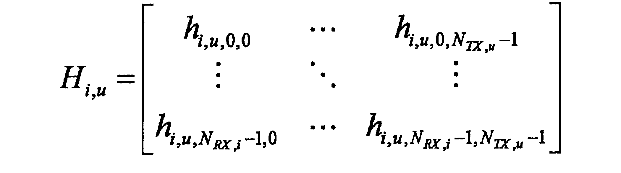
- Received signal r u of the user u may be expressed as follows.
- the matrix H u, i is the channel response matrix for cell i and user u.
- Each element of the matrix H u, i is basically a complex number.
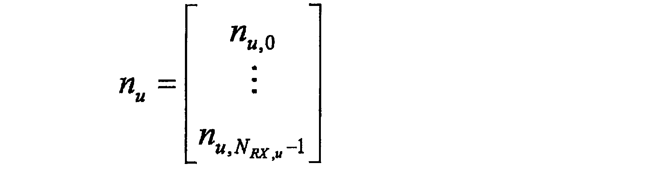
- the vector n u is noise included in the received signal r u of the user u.
- the noise includes thermal noise and interference from other systems.
- the average power of noise is expressed as follows.
- Received signal r u as follows, can be represented by the desired signal and other signals.
- the first term on the right side is the desired signal of the user u
- the second term is the interference in the serving cell i of the user u (intra-cell interference, multi-user interference or multi-access)
- the third term is interference from cells other than the cell i (called inter-cell interference).
- the received signal can be expressed as follows.
- orthogonal multiple access there is no intra-cell interference, and signals of other users v are not multiplexed in the same radio resource in other cells j.
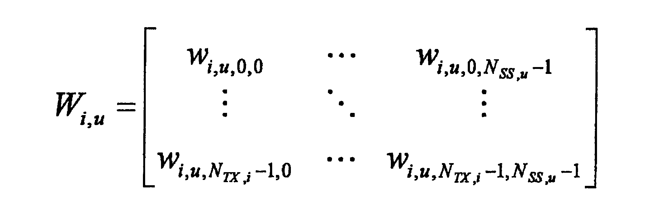
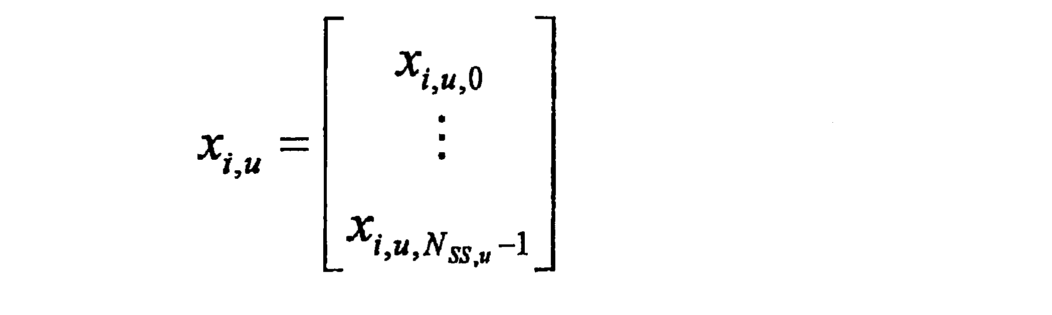
- the transmission signal transmitted by the user u in the cell i can be expressed in a vector format as follows.
- the number of transmission antennas is the number of user transmission antennas N TX, u .
- the matrix P i, u which is the power allocation coefficient matrix for user u in cell i, may be a diagonal matrix as in the downlink case.
- the user's signal and another user's signal are not multiplexed in the user, so the received signal of the base station of cell i can be expressed as: .
- the base station needs to decode all signals from multiple users in the cell. It should also be noted that the channel response matrix varies from user to user.
- the received signal can be expressed as follows.
- the first term on the right side is the desired signal of the user u
- the second term is the interference in the serving cell i of the user u (referred to as intra-cell interference, multi-user interference or multi-access interference, etc.)
- the third term is interference from cells other than cell i (called inter-cell interference).
- the received signal can be expressed as follows.
- orthogonal multiple access there is no intra-cell interference, and signals of other users v are not multiplexed in the same radio resource in other cells j.
- a transmission signal sequence (that is, a signal) composed of a bit string is transmitted after modulation processing.
- the bit string is associated with signal points (also referred to as symbols) on the complex plane.
- the correspondence between the bit string and the signal point is also referred to as constellation, constellation mapping, symbol mapping, or symbol arrangement.
- Gray mapping means that a combination of bit strings corresponding to adjacent symbols on the complex plane differs by at most one bit.
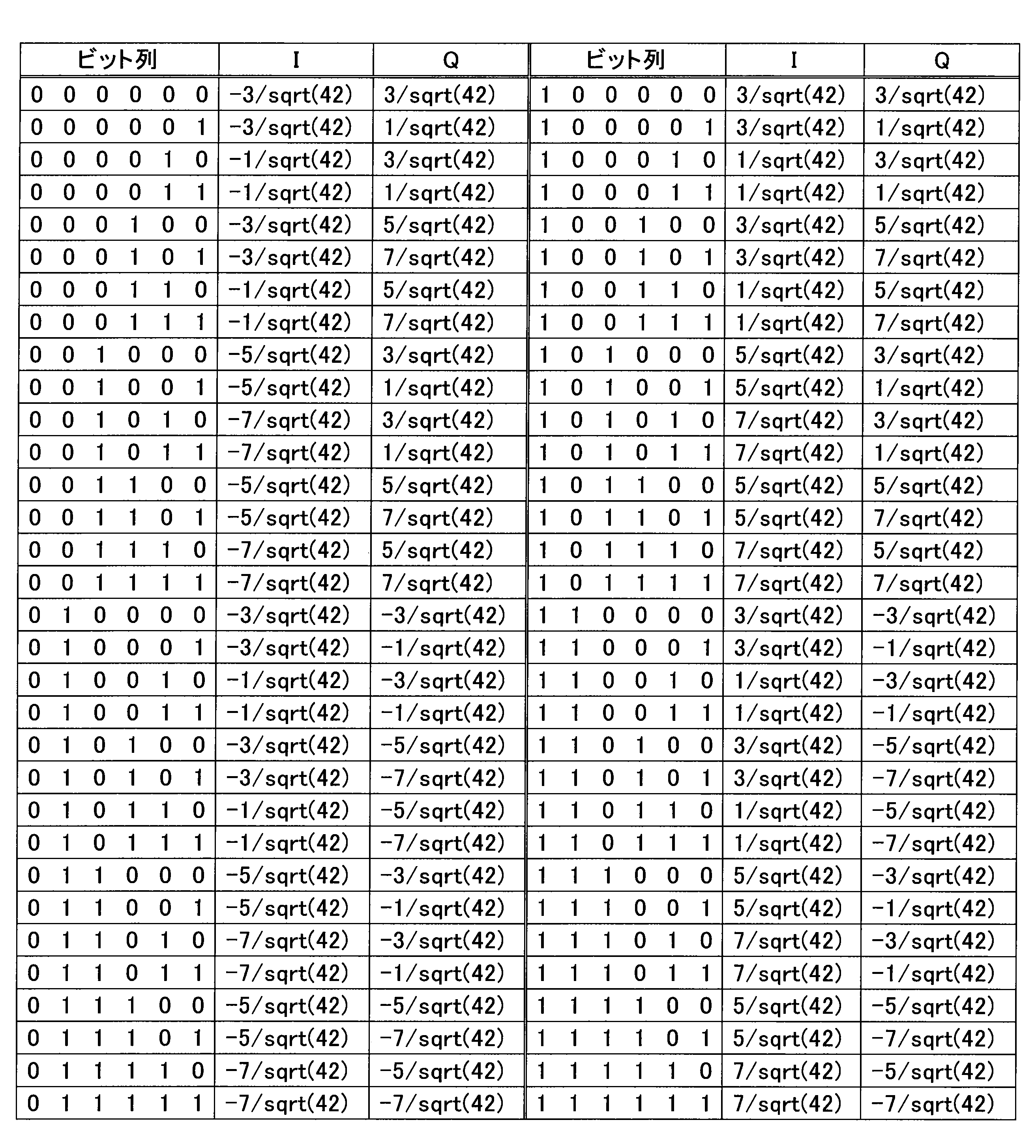
- Tables 1 to 3 below show the correspondence between the bit string and the coordinates on the IQ plane of the gray mapped constellation in each of the 64QAM, 16QAM, and QPSK modulation schemes.
- Table 1 shows the correspondence in 64QAM that can express 6 bits per symbol.
- Table 2 shows the correspondence in 16QAM that can represent 4 bits per symbol.
- Table 3 shows the correspondence in QPSK that can represent 2 bits per symbol.
- signals are multiplexed after power allocation is performed on the modulated symbols.
- the multiplexed constellation that is, the correspondence between a set of multiplexed bit strings and symbols
- FIG. 4 shows a constellation after multiplexing when two signals modulated using QPSK are multiplexed.
- FIG. 4 is a diagram showing an example of a constellation of SPC multiplexed signals.
- the number attached to each symbol indicates the corresponding bit string.
- the magnitude relationship between the amplitudes of the two QPSK constellations (reference numerals 20A and 20B) corresponds to the magnitude relationship of the allocated power.
- the bit string corresponding to the symbol of the constellation (symbol 20C) of the SPC multiplexed signal the first two bits correspond to the bit string of the signal with a large allocated power (that is, the signal to which the constellation 20A is applied). .
- Each corresponding bit string is underlined in the figure.
- the latter two bits correspond to a bit string of a signal with low power allocation (that is, a signal to which constellation 20B is applied).
- Each corresponding bit string is overlined in the figure.
- each of the two QPSK constellations 20A and 20B is gray-mapped.
- the constellation 20C of the SPC multiplexed signal is not gray-mapped.
- the corresponding bit strings of adjacent symbols across the I axis or the Q axis are different by 2 bits. For example, “0001” and “0100” adjacent to each other across the I-axis are different in a total of 2 bits, the second bit and the fourth bit.
- the receiving apparatus fails to decode, for example, when decoding as a symbol adjacent to the correct symbol with the I-axis or Q-axis in between, two or more bits Errors can occur.
- the occurrence of such a bit error of 2 bits or more becomes a cause of deterioration of decoding characteristics of the receiving device. Note that such a bit error occurs particularly prominently when a maximum likelihood detection (MLD) method is adopted on the receiving device side.
- MLD maximum likelihood detection
- gray mapping is realized not only before multiplexing but also for constellations after SPC multiplexing. Therefore, in this embodiment, a mechanism for realizing this is provided.
- FIG. 5 is an explanatory diagram illustrating an example of a schematic configuration of the system 1 according to an embodiment of the present disclosure.
- the system 1 includes a base station 100 and a terminal device 200.
- the terminal device 200 is also called a user.
- the user may also be called user equipment (UE).
- the UE here may be a UE defined in LTE or LTE-A, and may more generally mean a communication device.
- Base station 100 is a base station of a cellular system (or mobile communication system).
- the base station 100 performs wireless communication with a terminal device (for example, the terminal device 200) located in the cell 10 of the base station 100.
- a terminal device for example, the terminal device 200
- the base station 100 transmits a downlink signal to the terminal device and receives an uplink signal from the terminal device.
- Terminal device 200 The terminal device 200 can communicate in a cellular system (or mobile communication system).
- the terminal device 200 performs wireless communication with a base station (for example, the base station 100) of the cellular system.
- a base station for example, the base station 100
- the terminal device 200 receives a downlink signal from the base station and transmits an uplink signal to the base station.
- the base station 100 performs wireless communication with a plurality of terminal devices by non-orthogonal multiple access. More specifically, the base station 100 performs wireless communication with a plurality of terminal devices by multiplexing / multiple access using power allocation. For example, the base station 100 performs wireless communication with a plurality of terminal devices by multiplexing / multiple access using SPC.
- the base station 100 performs wireless communication with a plurality of terminal devices by multiplexing / multiple access using SPC in the downlink. More specifically, for example, the base station 100 multiplexes signals to a plurality of terminal devices using SPC. In this case, for example, the terminal device 200 removes one or more other signals as interference from the multiplexed signal including the desired signal (that is, the signal to the terminal device 200), and decodes the desired signal.
- the desired signal that is, the signal to the terminal device 200
- the base station 100 may perform wireless communication with a plurality of terminal apparatuses by multiplexing / multiple access using SPC in the uplink instead of the downlink or together with the downlink.
- the base station 100 may decode each of the signals from a multiplexed signal including signals transmitted by the plurality of terminal devices.
- FIG. 6 is a block diagram illustrating an exemplary configuration of the base station 100 according to an embodiment of the present disclosure.
- the base station 100 includes an antenna unit 110, a wireless communication unit 120, a network communication unit 130, a storage unit 140, and a processing unit 150.
- Antenna unit 110 The antenna unit 110 radiates a signal output from the wireless communication unit 120 to the space as a radio wave. Further, the antenna unit 110 converts radio waves in space into a signal and outputs the signal to the wireless communication unit 120.
- the wireless communication unit 120 transmits and receives signals.
- the radio communication unit 120 transmits a downlink signal to the terminal device and receives an uplink signal from the terminal device.
- the network communication unit 130 transmits and receives information.
- the network communication unit 130 transmits information to other nodes and receives information from other nodes.
- the other nodes include other base stations and core network nodes.
- Storage unit 140 The storage unit 140 temporarily or permanently stores a program for operating the base station 100 and various data.
- Processing unit 150 provides various functions of the base station 100.
- the processing unit 150 includes a selection unit 151 and a transmission processing unit 153.
- the processing unit 150 may further include other components other than these components. That is, the processing unit 150 can perform operations other than the operations of these components.
- the operations of the selection unit 151 and the transmission processing unit 153 will be described in detail later.
- the base station 100 (for example, the transmission processing unit 153) multiplexes transmission signal sequences of a plurality of power layers using power allocation. That is, the transmission signal sequence transmitted from base station 100 is multiplexed using power allocation.
- the expression “multiplex the power layer” is synonymous with “multiplex the signal of the power layer”.
- the expression “allocating power to the power layer” is synonymous with “allocating power to signals in the power layer”.
- the base station 100 performs power allocation according to an arbitrary standard.
- an example of the relationship between the power layer and the allocated power will be described with reference to FIG.
- FIG. 7 is an explanatory diagram for explaining an example of power allocation to the power layer.
- the horizontal axis is a frequency resource and / or a time resource, and the vertical axis is a power level (allocated power level).
- N power layers power layer 0 to power layer N-1
- the numbers from 0 to N-1 are also referred to as power layer indexes.
- the height of the power layer (that is, the width in the vertical direction) indicates the height of power to which the power layer is assigned.
- a high power assigned as the index is smaller power layer, for example, the power P 0 is higher than P 1, P 1 is higher than P 2, P N-1 is the lowest.
- a transmission signal sequence multiplexed using SPC is transmitted using at least one power layer.
- the relationship between the power layer index and the allocated power is not limited to the example shown in FIG.
- the index of the power layer to which the highest power is allocated may be other than 0, and the power allocated to the power layer with a smaller index may be lower.
- the base station 100 selects a constellation to be applied to each transmission signal sequence to be multiplexed. Then, the base station 100 (for example, the transmission processing unit 153) applies the selected constellation to each transmission signal sequence.
- a bit string of a transmission signal sequence having higher allocated power than the other is referred to as a first bit string
- a bit string of a transmission signal sequence having lower allocated power than the other is referred to as a second bit string.
- the base station 100 selects a constellation to be applied to each of the first bit string and the second bit string.
- a constellation applied to the first bit string is also referred to as a first constellation
- a constellation applied to the second bit string is also referred to as a second constellation.
- the first and second constellations applied to individual bit strings are assumed to be gray-mapped.
- the base station 100 selects a constellation to be applied to the other bit string according to one bit string. Specifically, the base station 100 selects the second constellation corresponding to the symbol position of the first bit string in the first constellation applied to the first bit string.
- FIG. 8 is an explanatory diagram for explaining an example of processing in a transmission apparatus (for example, the wireless communication unit 120) that performs such selection.
- the physical layer setting controller (for example, operating based on control by the processing unit 150) acquires information from a modulator that modulates a bit string of the first transmission signal sequence. Specifically, the physical layer setting controller acquires information indicating the symbol position of the first bit string in the first constellation applied to the first bit string. Then, as illustrated in FIG.
- the physical setting controller instructs the modulator that modulates the bit string of the second transmission signal sequence. Specifically, the physical layer setting controller instructs to apply the second constellation selected based on the acquired information. Electric power is allocated to each of the signals output from the modulators. For example, high power is assigned to signals in the first transmission signal sequence, and low power is assigned to signals in the second transmission signal sequence. Thereafter, through various processes, the signals of the two transmission signal sequences are SPC multiplexed.
- the base station 100 sets the second bit string so that the bit strings corresponding to the end symbols in the adjacent direction of the second constellation corresponding to the adjacent symbols in the first constellation are the same.
- the adjacent direction in the present embodiment is either the I direction (that is, the I axis positive direction or the I axis negative direction) or the Q direction (that is, the Q axis positive direction or the Q axis negative direction).
- FIG. 9 is an explanatory diagram for explaining a constellation selection process according to the present embodiment.
- a first constellation applied to the first bit string is denoted by reference numeral 21A.
- the second constellation applied to the second bit string is indicated by reference numerals 21B to 21E.
- the first bit string is “00”
- the second constellation 21B is applied to the second bit string.
- the second constellation 21C is applied to the second bit string.
- the first bit string is “11”
- the second constellation 21D is applied to the second bit string.
- the first bit string is “01”
- the second constellation 21E is applied to the second bit string.
- the meanings of the underline and the overline attached to each bit string in the figure are the same as those in FIG.
- the second constellation corresponding to, for example, “00” and “10”, which are adjacent symbols in the first constellation 21A, are the second constellation 21B and the code 21C, respectively.
- the direction “10” for “00” is the negative direction of the I axis.
- the direction “00” for “10” is the positive direction of the I axis. Therefore, the bit string (that is, “10” and “11”) corresponding to the symbol at the end in the negative direction of the I-axis of the second constellation 21B corresponding to “00” in the first constellation 21A is the first constellation 21A.
- bit string that is, “10” and “11”
- bit string that is, “10” and “11”
- the above relationship can also be understood as that the second constellations corresponding to the adjacent symbols in the first constellation are inverted in the adjacent direction.
- the second constellation 21 ⁇ / b> C is obtained by inverting the second constellation 21 ⁇ / b> B in the negative direction of the I axis (that is, with the Q axis).
- the second constellation 21B is obtained by inverting the second constellation 21C in the positive direction of the I axis (that is, with the Q axis).
- Such a relationship holds similarly for the other adjacent symbols in the first constellation, “10” and “11”, “11” and “01”, and “01” and “00”. ing.
- the above relationship determines one symbol serving as a reference in the first constellation, and selects the second constellation according to the deviation of the symbol corresponding to the first bit string from the reference symbol.
- the base station 100 2 is selected by inverting the constellation of 2 in the positive direction of the I axis (or in the negative direction of the I axis) (that is, in the Q axis).
- the base station 100 corresponds to the reference symbol. 2 is selected by inverting the constellation of 2 in the positive direction of the Q axis (or in the negative direction of the Q axis) (that is, on the I axis). In addition, the base station 100 determines that symbols corresponding to the first bit string are shifted from the reference symbol by an odd number in the I-axis positive direction (or I-axis negative direction) and Q-axis positive direction (or Q-axis negative direction).
- the second constellation corresponding to the reference symbol is moved in the positive direction of the I axis (or in the negative direction of the I axis) and in the positive direction of the Q axis (or in the negative direction of the Q axis) (ie, in the Q axis and the I axis). ) Select the inverted one.
- a symbol corresponding to “00” in the first constellation indicated by reference numeral 21A is set as a reference symbol.
- the base station 100 since the symbol corresponding to “10” is one symbol shifted in the negative direction of the I axis from the reference symbol, the base station 100 uses the second constellation 21B corresponding to the reference symbol as the Q axis.
- the second constellation 21 ⁇ / b> C inverted at is selected.
- the base station 100 uses the I axis to generate the second constellation 21B corresponding to the reference symbol.
- the inverted second constellation 21E is selected.
- the base station 100 performs the second constellation corresponding to the reference symbol.
- a second constellation 21D obtained by inverting 21B about the Q axis and the I axis is selected.
- bit strings corresponding to adjacent symbols are different from each other by 1 bit.
- the corresponding bit strings of adjacent symbols across the I axis or the Q axis are different from each other by 1 bit. For example, “0001” and “0101” adjacent to each other across the I axis are different from each other only in the second bit.
- gray mapping is realized not only before multiplexing but also after constellation after SPC multiplexing.
- the above-described constellation selection is first performed in relation to the two transmission signal sequences, and then the multiplexed transmission signal sequence and the multiplexed transmission signal sequence are multiplexed.
- the constellation selection described above is performed in relation to the transmission signal sequence before conversion. That is, the present technology can be applied even when the number of transmission signal sequences to be multiplexed is three or more.
- QPSK has been described as an example.
- the present technology may employ any modulation scheme such as BPSK or 16QAM. Further, the modulation scheme may be different between the first bit string and the second bit string.
- Tables 4 to 7 below show the correspondence between the bit strings and the coordinates on the IQ plane of the first constellation 21A and the second constellations 21B to 21E.
- Table 4 shows the correspondence between the first constellation 21A and the second constellation 21B.
- Table 5 shows the correspondence in the second constellation 21C, that is, the correspondence reversed on the Q axis.
- Table 6 shows the correspondence relationship in the second constellation 21E, that is, the correspondence relationship inverted on the I axis.
- Table 7 shows the correspondence relationship in the second constellation 21D, that is, the correspondence relationship inverted on the I axis and the Q axis.
- Tables 8 to 11 below show the correspondence between the bit strings and the coordinates on the IQ plane in the first constellation and the second constellation in the case of 16QAM.
- Table 8 shows the correspondence between the first constellation and the second constellation that is not inverted.
- Table 9 shows a correspondence relationship in the second constellation obtained by inverting the first constellation on the Q axis.
- Table 10 shows a correspondence relationship in the second constellation obtained by inverting the first constellation about the I axis.
- Table 11 shows a correspondence relationship in the second constellation obtained by inverting the first constellation on the I axis and the Q axis.
- Base station 100 determines the content of signal processing subsequent to modulation (that is, application of the first and second constellations). Accordingly, it may be determined whether to apply the second constellation selected by the selection process to the second bit string. Thereby, for example, even when the second constellation selected by the selection process is applied, the selection process can be omitted when gray mapping is not realized. Note that when it is determined not to be applied, for example, a default constellation (for example, the same as the first constellation) is applied.
- the base station 100 selects the above selection when the same transmission weighting is applied to both the transmission signal sequence of the first bit string and the transmission signal sequence of the second bit string, or when no transmission weighting is applied to any of them.
- the second constellation selected by processing may be applied to the second bit string. This is because when different transmission weights are applied, it becomes difficult to realize gray mapping, as will be described in detail later with reference to FIG. It is also for backward compatibility.
- transmission weighting includes, for example, precoding or beam-forming, and weighting is performed using complex coefficients.
- the spatial multiplexing number in spatial multiplexing (such as Spatial Multiplexing or Spatial Division Multiplexing) or spatial diversity (Transmit Diversity, Space-Time Block / Trellis Coding, or Space-Frequency Block / Trellis Coding) in MIMO Number of layers) and the number of transmission antennas.
- the base station 100 converts the second constellation selected by the selection process into the second bit string when the same spatial multiplexing number of spatial multiplexing processing or spatial diversity processing is applied to both transmission signal sequences. You may apply. Further, the base station 100 may apply the second constellation selected by the selection process to the second bit string when the same number of transmission antennas are used for both transmission signal sequences.
- the base station 100 sets the second constellation selected by the selection process according to the channel used for transmission of the transmission signal sequence of the first bit string and the transmission signal sequence of the second bit string to the second bit string. It may be determined whether or not to apply. Specifically, the base station 100 determines that both the transmission signal sequence of the first bit string and the transmission signal sequence of the second bit string are a data channel (Data Channel), a common channel (Shared Channel), or a dedicated channel (Dedicated). When transmitting using (Channel), the second constellation selected by the selection process is applied to the second bit string. This is because SPC multiplexing is basically not suitable for a channel such as a control channel that is received by a plurality of receiving apparatuses from the viewpoint of compatibility.
- Data Channel data channel
- Shared Channel Shared Channel
- Dedicated dedicated channel
- the base station 100 converts the second constellation selected by the selection process into the second bit string according to the destinations of the first bit string transmission signal sequence and the second bit string transmission signal sequence. Whether or not to apply may be determined. For example, when the destination of each of the transmission signal sequence of the first bit string and the transmission signal sequence of the second bit string is a single device (that is, unicast), the base station 100 performs the selection process described above. The second constellation selected by (2) may be applied to the second bit string. Also, the base station 100 applies the second constellation selected by the selection process to the second bit string when the destinations of the transmission signal sequence of the first bit string and the transmission signal sequence of the second bit string are different. May be.
- the base station 100 performs the selection process when the destination of each of the transmission signal sequence of the first bit string and the transmission signal sequence of the second bit string is a plurality of devices (that is, multicast or broadcast).
- the second constellation selected by (2) may be applied to the second bit string.
- the base station 100 does not depend on the destination of the transmission signal sequence of the second bit string, and the second constant selected by the above selection process. May be applied to the second bit string.
- FIG. 10 is a flowchart illustrating an example of the flow of multiple processing executed in the base station 100 according to the present embodiment.
- the base station 100 acquires the modulation level applied to the target signal (step S102).
- the modulation level corresponds to each modulation method such as BPSK, QPSK, 16QAM, and 64QAM.
- the modulation level may be the number of bits per symbol (1 bit / symbol for BPSK, 2 bit / symbol for QPSK, 4 bit / symbol for 16 QAM, 6 bit / symbol for 64 QAM).
- the base station 100 determines whether or not the target signal is multiplexed with other signals on at least a part of the same frequency resource or time resource (step S104). Further, when it is determined that the signals are multiplexed (step S104 / YES), the base station 100 (for example, the selection unit 151) allocates less power to the target signal than other signals to be multiplexed. It is determined whether or not (step S106).
- the base station 100 When it is determined that the power allocated to the target signal is smaller (step S106 / YES), the base station 100 (for example, the selection unit 151) performs constellation selection processing (step S108). Specifically, the base station 100 uses the second constellation corresponding to the symbol position of the first bit string in the first constellation applied to the bit string of another signal to be multiplexed (that is, the first transmission signal sequence). Select a configuration. On the other hand, when it is determined that the power allocated to the target signal is larger (step S106 / NO), the base station 100 (for example, the selection unit 151) selects a predetermined constellation (step S110). For example, the base station 100 (selection unit 151) selects a default constellation (for example, the same one as the first constellation).
- the base station 100 applies the selected constellation to the target signal (that is, the second transmission signal sequence) (step S112). Thereafter, the base station 100 (for example, the transmission processing unit 153) multiplexes the modulated target signal with other signals (step S114).
- the base station 100 when it is determined that the target signal is not multiplexed with other signals on at least a part of the same frequency resource or time resource (step S104 / NO), the base station 100 (for example, the selection unit 151) A predetermined constellation is selected (step S116). For example, the base station 100 (selection unit 151) selects a default constellation (for example, the same one as the first constellation). Then, the base station 100 (for example, the transmission processing unit 153) applies the selected constellation to the target signal (that is, the second transmission signal sequence) (step S118).
- FIG. 11 is a flowchart showing an example of the flow of constellation selection processing executed in the base station 100 according to the present embodiment. This flow corresponds to step S108 in FIG.
- the base station 100 acquires the modulation level applied to the first transmission signal sequence (step S202).
- the base station 100 acquires the modulation level applied to the second transmission signal sequence (step S204).
- the base station 100 specifies a symbol corresponding to the first bit string in the first constellation (step S206).
- the base station 100 sets a constellation corresponding to the reference symbol as a candidate for the second constellation (step S208).
- the base station 100 determines whether or not the number of symbols corresponding to the first bit string is shifted from the reference symbol by an odd number in the I-axis positive direction (or I-axis negative direction) ( Step S210).
- the base station 100 determines whether or not the number of symbols corresponding to the first bit string is shifted from the reference symbol by an odd number in the I-axis positive direction (or I-axis negative direction) (Ste S210).
- the base station 100 (for example, the selection unit 151) inverts the second constellation candidate on the Q axis (step S212).
- the processing according to step S212 is skipped.
- the base station 100 determines whether or not the number of symbols corresponding to the first bit string is shifted from the reference symbol by an odd number in the positive Q-axis direction (or negative Q-axis direction). (Step S214). If it is determined that there is an odd number of deviations in the positive direction of the Q axis (step S214 / YES), the base station 100 (for example, the selection unit 151) inverts the second constellation candidate on the I axis (step S216). ). When it is determined that an even number is shifted in the positive direction of the Q axis (step S214 / NO), the processing according to step S216 is skipped.
- FIG. 12 is a flowchart illustrating an example of a flow of constellation application processing executed in the base station 100 according to the present embodiment.
- the base station 100 acquires the modulation level applied to the target signal (step S302). Thereafter, the base station 100 (for example, the selection unit 151) determines whether to perform a constellation selection process or a predetermined constellation in steps S304 to S316.
- the base station 100 determines whether or not the target signal is multiplexed with another signal on at least a part of the same frequency resource or time resource (step S304). Next, the base station 100 determines whether or not the power allocated to the target signal is smaller than other signals to be multiplexed (step S306). Next, the base station 100 determines whether or not the same transmission weighting as that of other signals is applied to the target signal (step S308). Next, the base station 100 determines whether or not the same transmission mode as other signals is applied to the target signal (step S310). Next, the base station 100 determines whether or not the same spatial multiplexing number as other signals is applied to the target signal (step S312). Next, the base station 100 determines whether a data channel, a common channel, or a dedicated channel is used for the target signal (step S314). Next, the base station 100 determines whether or not the target signal is unicast (step S316).
- the base station 100 When all of these condition determinations are YES, the base station 100 (for example, the selection unit 151) performs a constellation selection process (step S318).
- the processing here is the same as step S108 in FIG. 10, and is as described above with reference to FIG.
- the base station 100 selects a predetermined constellation (step S320).
- the base station 100 applies the selected constellation to the target signal (step S322).
- the constellation application process including the determination based on the signal processing subsequent to the modulation is completed.
- FIG. 15 is a flowchart illustrating an example of the flow of constellation application processing executed in the base station 100 according to the present embodiment.
- the flow shown in FIG. 15 is obtained by shifting Step S314 and Step S317 of FIG. 14 to the previous stage from Step S304, and the contents are the same, and detailed description thereof is omitted here.
- the second constellation is selected in order to realize gray mapping even in the constellation after multiplexing, and the selected second constellation is applied to the second bit string.
- a signal capable of realizing gray mapping even in the constellation after multiplexing is generated.
- the second bit string is converted into gray level even in the constellation after multiplexing by conversion processing after modulation (that is, phase and / or amplitude conversion, which may also be regarded as symbol arrangement conversion).
- conversion processing after modulation that is, phase and / or amplitude conversion, which may also be regarded as symbol arrangement conversion.
- a signal that can be mapped is generated.
- the final output is the same when the second constellation is selected and in this modification.
- the process for generating a signal capable of realizing gray mapping even in the constellation after multiplexing may be realized by selecting the second constellation or may be realized by the conversion process after modulation. Good.
- the difference between these methods is an implementation difference, not an essential technical difference.
- the physical layer setting controller instructs to perform conversion for realizing the same symbol arrangement as the result of applying the second constellation selected in the transmitter shown in FIG. 8 in the modulator. .
- Power is assigned to each of the first transmission signal sequence signal output from the modulator and the second transmission signal sequence signal output from the converter. For example, high power is assigned to signals in the first transmission signal sequence, and low power is assigned to signals in the second transmission signal sequence. Thereafter, through various processes, the signals of the two transmission signal sequences are SPC multiplexed.
- FIG. 17 it is a flowchart showing an example of a flow of multiple processing executed in the base station 100 according to the present modification.
- the base station 100 selects a predetermined constellation (step S134).
- the base station 100 selects a default constellation (for example, the same one as the first constellation).
- the base station 100 applies the selected constellation to the target signal (that is, the second transmission signal sequence) (step S136).
- the base station 100 (for example, the transmission processing unit 153) multiplexes the target signal with other signals ( Step S144).
- FIG. 18 is an explanatory diagram for describing technical features of the base station 100 according to the present embodiment.
- the physical layer setting controller (for example, operating based on the control by the processing unit 150) performs bit selection and bit rearrangement on each of the first transmission signal sequence and the second transmission signal sequence. Apply. At this time, the physical layer setting controller extracts a bit string multiplexed with one symbol from each transmission signal sequence. Then, the physical layer setting controller modulates the bit strings extracted from the respective transmission signal sequences together.
- the physical layer setting controller selects 2 bits from each of the first transmission signal sequence and the second transmission signal sequence, and modulates a total of 4 bits by 16QAM. At that time, the physical layer setting controller arranges the 2 bits of the transmission signal sequence on the side where the allocated power is larger as the first half 2 bits and the 2 bits of the transmission signal sequence on the side where the allocated power is smaller as the latter 2 bits. Change. For 16QAM modulation, a gray mapped normal constellation for 16QAM is typically applied. Thereby, even if the reception apparatus fails in decoding, for example, when decoding as a symbol adjacent to a correct symbol, a bit error of 2 bits or more does not occur, and the bit error is at most 1 bit.
- the same output as that of the transmission apparatus according to the first embodiment shown in FIG. 8 can be obtained.
- the modulated signal is then subjected to various signal processing such as resource element mapping and OFDM modulation.
- the base station 100 acquires a modulation level applied to a transmission signal (step S402).
- 16QAM is assumed as an example.
- the base station 100 (for example, the transmission processing unit 153) arranges and combines the extracted bit strings at bit positions corresponding to the allocated power (step S406). For example, the base station 100 combines 2 bits of the transmission signal sequence with higher allocated power into the first half 2 bits and 2 bits of the transmission signal sequence with lower allocated power into the latter 2 bits.
- the base station 100 (for example, the transmission processing unit 153) modulates the synthesized bit string (step S408). For example, the base station 100 modulates the combined 4-bit bit sequence using a gray mapped normal constellation for 16QAM.
- a symbol “1011” surrounded by a broken line and a symbol “1100” that is adjacent (for example, located at the closest distance) across the I axis are different by 2 bits. For this reason, when the receiving apparatus fails in decoding and decodes, for example, as a symbol adjacent to the correct symbol across the I axis or the Q axis, a bit error of 2 bits or more may occur. The occurrence of such a bit error of 2 bits or more becomes a cause of deterioration of decoding characteristics of the receiving device.
- symbol arrangement is also referred to as quasi-non-gray mapping.
- symbol arrangement is also referred to as quasi-gray mapping.
- the base station 100 according to the present embodiment realizes quasi-gray mapping when different transmission weights are applied.
- the number of transmission signal sequences to be multiplexed is two.
- the number of transmission signal sequences to be multiplexed may be three or more.
- the transmission weights to be applied differ in at least one set of the plurality of transmission signal sequences.
- the relationship of power regarding the first bit string and the second bit string is the same as in the first embodiment.
- the base station 100 selects a constellation to be applied to the other bit string according to one bit string. Specifically, the base station 100 selects the second constellation corresponding to the symbol position of the first bit string in the first constellation applied to the first bit string.
- the transmission apparatus for example, the wireless communication unit 120
- the transmission apparatus that performs such selection can be realized as, for example, the above-described FIG. 8 or FIG.
- the second constellation selected by the base station 100 is applied to the transmission weight applied to each of the transmission signal sequence of the first bit string and the transmission signal sequence of the second bit string, and the first bit string.
- the reference constellation is rotated by an amount corresponding to the symbol position of the first bit string in the first constellation. This point will be specifically described with reference to FIG. 21 regarding two signals modulated using QPSK.
- FIG. 21 is an explanatory diagram for explaining a constellation selection process according to the present embodiment.
- a first constellation applied to the first bit string is denoted by reference numeral 23A.
- the second constellation applied to the second bit string is indicated by reference numerals 23B to 23E.
- the first bit string is “11”
- the second constellation 21B is applied to the second bit string.
- the second constellation 21C is applied to the second bit string.
- the first bit string is “00”
- the second constellation 21D is applied to the second bit string.
- the first bit string is “01”
- the second constellation 21E is applied to the second bit string.
- the meanings of the underline and the overline attached to each bit string in the figure are the same as those in FIG.
- the transmission weight applied to each of the transmission signal sequence of the first bit string and the transmission signal sequence of the second bit string is different. Therefore, there is a phase difference between the first constellation and the second constellation.
- the reference constellation is set as the first constellation 23A.
- the base station 100 selects a constellation obtained by rotating the reference constellation by 0 ⁇ n degrees as the second constellation 2B.
- FIG. 21 illustrates the selected constellation by further reflecting the phase difference caused by the difference in transmission weight.
- the second constellation 2B may be regarded as a reference constellation.
- the rotation direction is clockwise.
- the base station 100 selects a constellation obtained by rotating the reference constellation by 90 ⁇ n degrees as the second constellation 2C.
- the base station 100 selects a constellation obtained by rotating the reference constellation 180 ⁇ n degrees as the second constellation 2D.
- the base station 100 selects a constellation obtained by rotating the reference constellation by 270 ⁇ n degrees as the second constellation 2E. Note that n is calculated by the following mathematical formula.
- FIG. 23 is a flowchart illustrating an example of the flow of constellation selection processing executed in the base station 100 according to the present embodiment.
- Each of the antennas 810 has a single or a plurality of antenna elements (for example, a plurality of antenna elements constituting a MIMO antenna), and is used for transmission and reception of radio signals by the base station apparatus 820.
- the eNB 800 includes a plurality of antennas 810 as illustrated in FIG. 24, and the plurality of antennas 810 may respectively correspond to a plurality of frequency bands used by the eNB 800, for example. 24 shows an example in which the eNB 800 has a plurality of antennas 810, the eNB 800 may have a single antenna 810.
- the controller 821 may be a CPU or a DSP, for example, and operates various functions of the upper layer of the base station apparatus 820. For example, the controller 821 generates a data packet from the data in the signal processed by the wireless communication interface 825, and transfers the generated packet via the network interface 823. The controller 821 may generate a bundled packet by bundling data from a plurality of baseband processors, and may transfer the generated bundled packet. In addition, the controller 821 is a logic that executes control such as radio resource control, radio bearer control, mobility management, inflow control, or scheduling. May have a typical function. Moreover, the said control may be performed in cooperation with a surrounding eNB or a core network node.
- the memory 822 includes RAM and ROM, and stores programs executed by the controller 821 and various control data (for example, terminal list, transmission power data, scheduling data, and the like).
- the network interface 823 is a communication interface for connecting the base station device 820 to the core network 824.
- the controller 821 may communicate with the core network node or other eNB via the network interface 823.
- the eNB 800 and the core network node or another eNB may be connected to each other by a logical interface (for example, an S1 interface or an X2 interface).
- the network interface 823 may be a wired communication interface or a wireless communication interface for wireless backhaul.
- the network interface 823 may use a frequency band higher than the frequency band used by the wireless communication interface 825 for wireless communication.
- the wireless communication interface 825 supports any cellular communication scheme such as LTE (Long Term Evolution) or LTE-Advanced, and provides a wireless connection to terminals located in the cell of the eNB 800 via the antenna 810.
- the wireless communication interface 825 may typically include a baseband (BB) processor 826, an RF circuit 827, and the like.
- the BB processor 826 may perform, for example, encoding / decoding, modulation / demodulation, and multiplexing / demultiplexing, and each layer (for example, L1, MAC (Medium Access Control), RLC (Radio Link Control), and PDCP).
- Various signal processing of Packet Data Convergence Protocol
- Packet Data Convergence Protocol is executed.
- the BB processor 826 may have some or all of the logical functions described above instead of the controller 821.
- the BB processor 826 may be a module that includes a memory that stores a communication control program, a processor that executes the program, and related circuits. The function of the BB processor 826 may be changed by updating the program. Good.
- the module may be a card or a blade inserted into a slot of the base station apparatus 820, or a chip mounted on the card or the blade.
- the RF circuit 827 may include a mixer, a filter, an amplifier, and the like, and transmits and receives a radio signal via the antenna 810.
- the eNB 800 illustrated in FIG. 24 one or more components (selection unit 151 and / or transmission processing unit 153) included in the base station 100 described with reference to FIG. 6 are implemented in the wireless communication interface 825. Also good. Alternatively, at least some of these components may be implemented in the controller 821. As an example, the eNB 800 includes a module including a part (for example, the BB processor 826) or all of the wireless communication interface 825 and / or the controller 821, and the one or more components are mounted in the module. Good. In this case, the module stores a program for causing the processor to function as the one or more components (in other words, a program for causing the processor to execute the operation of the one or more components). The program may be executed.
- the module stores a program for causing the processor to function as the one or more components (in other words, a program for causing the processor to execute the operation of the one or more components). The program may be executed.
- the wireless communication interface 855 supports a cellular communication method such as LTE or LTE-Advanced, and provides a wireless connection to a terminal located in a sector corresponding to the RRH 860 via the RRH 860 and the antenna 840.
- the wireless communication interface 855 may typically include a BB processor 856 and the like.
- the BB processor 856 is the same as the BB processor 826 described with reference to FIG. 24 except that the BB processor 856 is connected to the RF circuit 864 of the RRH 860 via the connection interface 857.
- the wireless communication interface 855 includes a plurality of BB processors 856 as illustrated in FIG.
- 25 illustrates an example in which the wireless communication interface 855 includes a plurality of BB processors 856, the wireless communication interface 855 may include a single BB processor 856.
- connection interface 857 is an interface for connecting the base station device 850 (wireless communication interface 855) to the RRH 860.
- the connection interface 857 may be a communication module for communication on the high-speed line that connects the base station apparatus 850 (wireless communication interface 855) and the RRH 860.
- the RRH 860 includes a connection interface 861 and a wireless communication interface 863.
- connection interface 861 is an interface for connecting the RRH 860 (wireless communication interface 863) to the base station device 850.
- the connection interface 861 may be a communication module for communication on the high-speed line.
- the wireless communication unit 120 described with reference to FIG. 6 may be implemented in the wireless communication interface 863 (for example, the RF circuit 864).
- the antenna unit 110 may be mounted on the antenna 840.
- the network communication unit 130 may be implemented in the controller 851 and / or the network interface 853.
- the storage unit 140 may be mounted in the memory 852.
- the SPC has been described as an example of the multiplexing / multiple access technology using non-orthogonal resources, but the present technology is not limited to such an example.
- the present technology can be applied to a multiplexing / multiple access technology using any non-orthogonal resource such as IDMA (Interleave Division Multiple Access).
- IDMA Interleave Division Multiple Access
- the present technology is not limited to such an example.
- the present technology may be applied in uplink, and the present technology may also be applied in D2D communication, MTC communication, or the like.
- the apparatus according to any one of (1) to (3), wherein the transmission signal sequence is multiplexed using power allocation. (5) The apparatus according to (4), wherein the transmission signal sequence of the first bit string has a higher allocated power than the transmission signal sequence of the second bit string. (6) The apparatus according to any one of (1) to (5), wherein the first and second constellations indicate a gray-mapped correspondence relationship between a bit string and a symbol on a complex plane. (7) The processing unit determines whether or not to apply the second constellation to the second bit string in accordance with the content of signal processing subsequent to the application of the first and second constellations. The apparatus according to any one of (1) to (6).
- the processing unit When the same transmission weighting is applied to both the transmission signal sequence of the first bit string and the transmission signal sequence of the second bit string, or the transmission weighting is not applied to either, the processing unit The apparatus according to (7), wherein two constellations are applied to the second bit string. (9) When the same transmission mode is applied to both the transmission signal sequence of the first bit sequence and the transmission signal sequence of the second bit sequence, the processing unit converts the second constellation to the second bit sequence. The apparatus according to (7) or (8), which is applied to the above. (10) When the same spatial multiplexing number of spatial multiplexing processing or spatial diversity processing is applied to both the transmission signal sequence of the first bit string and the transmission signal sequence of the second bit string, the processing unit 10.
- the apparatus according to any one of (7) to (9), wherein the constellation is applied to the second bit string. (11) Whether the processing unit applies the second constellation to the second bit string in accordance with a channel used for transmission of the transmission signal sequence of the first bit string and the transmission signal series of the second bit string. The apparatus according to any one of (1) to (10), wherein a determination is made as to whether or not. (12) The processing unit is configured such that both the transmission signal sequence of the first bit string and the transmission signal sequence of the second bit string have a data channel (Data Channel), a common channel (Shared Channel), or a dedicated channel (Dedicated Channel). The apparatus according to any one of (1) to (11), wherein when transmitted using, the second constellation is applied to the second bit string.
- the processing unit converts the second constellation into the second bit string when the destination of each of the transmission signal sequence of the first bit string and the transmission signal series of the second bit string is a single device.
- the apparatus according to any one of (1) to (12), which is applied to the above.
- the processing unit applies the second constellation to the second bit string when the transmission signal sequence of the first bit string and the transmission signal sequence of the second bit string are different from each other.
- the device according to any one of (13) to (13).
- 15) The apparatus according to any one of (1) to (14), wherein the number of the transmission signal sequences to be multiplexed is two.
- the second constellation is a transmission weight applied to each of the transmission signal sequence of the first bit sequence and the transmission signal sequence of the second bit sequence, and a first constellation applied to the first bit sequence.
- a first constellation applied to a first bit sequence for a plurality of bit sequences to be multiplexed for each transmission signal sequence multiplexed in a resource block in which at least a part of a frequency resource or a time resource overlaps Applying a second constellation corresponding to a symbol position of the first bit string in the second bit string by a processor; Including methods.
- System 100 Base Station 110 Antenna Unit 120 Wireless Communication Unit 130 Network Communication Unit 140 Storage Unit 150 Processing Unit 151 Selection Unit 153 Transmission Processing Unit 200 Terminal Device
Landscapes
- Engineering & Computer Science (AREA)
- Signal Processing (AREA)
- Computer Networks & Wireless Communication (AREA)
- Physics & Mathematics (AREA)
- Probability & Statistics with Applications (AREA)
- Theoretical Computer Science (AREA)
- Digital Transmission Methods That Use Modulated Carrier Waves (AREA)
- Mobile Radio Communication Systems (AREA)
Abstract
Description
1.はじめに
1.1.SPC
1.2.コンスタレーション
1.3.技術的課題
2.構成例
2.1.システムの概略的な構成例
2.2.基地局の構成例
3.第1の実施形態
3.1.技術的特徴
3.2.処理の流れ
4.第2の実施形態
4.1.技術的特徴
4.2.処理の流れ
5.第3の実施形態
5.1.技術的課題
5.2.技術的特徴
5.3.処理の流れ
6.応用例
7.まとめ The description will be made in the following order.
1. 1. Introduction 1.1. SPC
1.2. Constellation 1.3. Technical issues Configuration example 2.1. Schematic configuration example of system 2.2. 2. Configuration example of base station First embodiment 3.1. Technical features 3.2. Flow of processing Second Embodiment 4.1. Technical features 4.2. Process flow Third Embodiment 5.1. Technical issues 5.2. Technical features 5.3. Flow of processing Application example 7. Summary
<1.1.SPC>
SPCでは、非直交するリソース(例えば、周波数リソース又は時間リソースの少なくとも一部が重複するリソースブロック)上で、電力レベルに差を設けることで複数の信号が多重化される。一般的には、電力レベルの配分は、送信装置の総送信電力の上限を加味しながら、送信装置と受信装置との間のパスロスの相対関係に基づいて設定されることが望ましい。なお、パスロスの代わりに、パスゲイン又は想定される受信品質(即ち、SINR)が用いられてもよい。 << 1. Introduction >>
<1.1. SPC>
In SPC, a plurality of signals are multiplexed by providing a difference in power level on non-orthogonal resources (for example, resource blocks in which at least part of frequency resources or time resources overlap). In general, the power level distribution is preferably set based on the relative relationship of the path loss between the transmission device and the reception device, taking into account the upper limit of the total transmission power of the transmission device. Instead of path loss, path gain or assumed reception quality (that is, SINR) may be used.
(a)送信装置における処理
図1及び図2は、SPCをサポートする送信装置における処理の一例を説明するための説明図である。図1を参照すると、例えば、ユーザA、ユーザB及びユーザCの各々のビットストリーム(例えば、トランスポートブロック)が処理される。これらのビットストリームの各々について、いくつかの処理(例えば、図2に示されるような)CRC(Cyclic Redundancy Check)符号化、FEC(Forward Error Correction)符号化、レートマッチング及びスクランブリング/インタリービング)が行われ、その後変調が行われる。そして、レイヤマッピング、電力割当て、プリコーディング、SPC多重、リソースエレメントマッピング、IDFT(Inverse Discrete Fourier Transform)/IFFT(Inverse Fast Fourier Transform)、CP(Cyclic Prefix)挿入、並びに、デジタルからアナログ及びRF(Radio Frequency)への変換などが行われる。 (1) Processing in Each Device (a) Processing in Transmission Device FIGS. 1 and 2 are explanatory diagrams for explaining an example of processing in a transmission device that supports SPC. Referring to FIG. 1, for example, each bitstream (eg, transport block) of user A, user B, and user C is processed. For each of these bitstreams, some processing (eg, as shown in FIG. 2) CRC (Cyclic Redundancy Check) coding, FEC (Forward Error Correction) coding, rate matching and scrambling / interleaving) And then modulation is performed. Then, layer mapping, power allocation, precoding, SPC multiplexing, resource element mapping, IDFT (Inverse Discrete Fourier Transform) / IFFT (Inverse Fast Fourier Transform), CP (Cyclic Prefix) insertion, and digital to analog and RF (Radio) Conversion to Frequency) is performed.
図3は、干渉除去を行う受信装置における処理の一例を説明するための説明図である。図3を参照すると、例えば、RF及びアナログからデジタルへの変換、CP除去(removal)、DFT(Discrete Fourier Transform)/FFT(Fast Fourier Transform)、並びに、ジョイント干渉除去、等化及び復号などが行われる。その結果、ユーザA、ユーザB及びユーザCの各々のビットストリーム(例えば、トランスポートブロック)が得られる。 (B) Processing in Receiving Device FIG. 3 is an explanatory diagram for explaining an example of processing in the receiving device that performs interference cancellation. Referring to FIG. 3, for example, conversion from RF and analog to digital, CP removal (removal), DFT (Discrete Fourier Transform) / FFT (Fast Fourier Transform), joint interference removal, equalization and decoding are performed. Is called. As a result, the bit streams (for example, transport blocks) of the users A, B, and C are obtained.
(a)ダウンリンク
次に、SPCが採用される場合のダウンリンクの送信信号及び受信信号を説明する。ここでは、HetNet(Heterogeneous Network)又はSCE(Small Cell Enhancement)などのマルチセルシステムを想定する。 (2) Transmitted signal and received signal (a) Downlink Next, a downlink transmitted signal and received signal when SPC is adopted will be described. Here, a multi-cell system such as HetNet (Heterogeneous Network) or SCE (Small Cell Enhancement) is assumed.


次に、SPCが採用される場合のアップリンクの送信信号及び受信信号を説明する。ここでは、HetNet又はSCEなどのマルチセルシステムを想定する。なお、信号などを表す記号として、ダウンリンクについて用いられた記号を流用する。 (B) Uplink Next, an uplink transmission signal and reception signal when SPC is employed will be described. Here, a multi-cell system such as HetNet or SCE is assumed. In addition, the symbol used about the downlink is diverted as a symbol showing a signal etc.


ビット列から成る送信信号系列(即ち、信号)は、変調処理後に送信される。変調の際、ビット列は複素平面上の信号点(シンボルとも称される)に対応付けられる。このビット列と信号点との対応関係は、コンスタレーション、コンスタレーションマッピング、シンボルマッピング、又はシンボル配置等とも称される。 <1.2. Constellation>
A transmission signal sequence (that is, a signal) composed of a bit string is transmitted after modulation processing. During modulation, the bit string is associated with signal points (also referred to as symbols) on the complex plane. The correspondence between the bit string and the signal point is also referred to as constellation, constellation mapping, symbol mapping, or symbol arrangement.


SPCでは、信号は、変調されたシンボルに電力割当てを施した上で多重化される。ここで、グレイマッピングされたコンスタレーションが適用された信号が多重される場合、その多重後のコンスタレーション(即ち、多重化されるビット列の集合とシンボルとの対応関係)は、グレイマッピングではなくなる場合がある。一例として、図4に、QPSKを用いて変調された2つの信号を多重した場合の、多重後のコンスタレーションを示す。 <1.3. Technical issues>
In SPC, signals are multiplexed after power allocation is performed on the modulated symbols. Here, when a signal to which a gray mapped constellation is applied is multiplexed, the multiplexed constellation (that is, the correspondence between a set of multiplexed bit strings and symbols) is not a gray mapping. There is. As an example, FIG. 4 shows a constellation after multiplexing when two signals modulated using QPSK are multiplexed.
<2.1.システムの概略的な構成例>
続いて、図5を参照して、本開示の一実施形態に係るシステム1の概略的な構成を説明する。図5は、本開示の一実施形態に係るシステム1の概略的な構成の一例を示す説明図である。図5を参照すると、システム1は、基地局100及び端末装置200を含む。ここでは、端末装置200は、ユーザとも呼ばれる。当該ユーザは、ユーザ機器(User Equipment:UE)とも呼ばれ得る。ここでのUEは、LTE又はLTE-Aにおいて定義されているUEであってもよく、より一般的に通信機器を意味してもよい。 << 2. Configuration example >>
<2.1. System schematic configuration example>
Subsequently, a schematic configuration of the
基地局100は、セルラーシステム(又は移動体通信システム)の基地局である。基地局100は、基地局100のセル10内に位置する端末装置(例えば、端末装置200)との無線通信を行う。例えば、基地局100は、端末装置へのダウンリンク信号を送信し、端末装置からのアップリンク信号を受信する。 (1)
端末装置200は、セルラーシステム(又は移動体通信システム)において通信可能である。端末装置200は、セルラーシステムの基地局(例えば、基地局100)との無線通信を行う。例えば、端末装置200は、基地局からのダウンリンク信号を受信し、基地局へのアップリンク信号を送信する。 (2) Terminal device 200
The terminal device 200 can communicate in a cellular system (or mobile communication system). The terminal device 200 performs wireless communication with a base station (for example, the base station 100) of the cellular system. For example, the terminal device 200 receives a downlink signal from the base station and transmits an uplink signal to the base station.
とりわけ本開示の一実施形態では、基地局100は、非直交多元接続により、複数の端末装置との無線通信を行う。より具体的には、基地局100は、電力割当てを用いた多重化/多元接続により、複数の端末装置との無線通信を行う。例えば、基地局100は、SPCを用いた多重化/多元接続により、複数の端末装置との無線通信を行う。 (3) Multiplexing / multiple access In particular, in an embodiment of the present disclosure, the
続いて、図6を参照して、本開示の一実施形態に係る基地局100の構成を説明する。図6は、本開示の一実施形態に係る基地局100の構成の一例を示すブロック図である。図6を参照すると、基地局100は、アンテナ部110、無線通信部120、ネットワーク通信部130、記憶部140及び処理部150を備える。 <2.2. Example of base station configuration>
Subsequently, a configuration of the
アンテナ部110は、無線通信部120により出力される信号を電波として空間に放射する。また、アンテナ部110は、空間の電波を信号に変換し、当該信号を無線通信部120へ出力する。 (1)
The
無線通信部120は、信号を送受信する。例えば、無線通信部120は、端末装置へのダウンリンク信号を送信し、端末装置からのアップリンク信号を受信する。 (2)
The
ネットワーク通信部130は、情報を送受信する。例えば、ネットワーク通信部130は、他のノードへの情報を送信し、他のノードからの情報を受信する。例えば、上記他のノードは、他の基地局及びコアネットワークノードを含む。 (3)
The
記憶部140は、基地局100の動作のためのプログラム及び様々なデータを一時的に又は恒久的に記憶する。 (4)
The
処理部150は、基地局100の様々な機能を提供する。処理部150は、選択部151及び送信処理部153を含む。なお、処理部150は、これらの構成要素以外の他の構成要素をさらに含み得る。即ち、処理部150は、これらの構成要素の動作以外の動作も行い得る。 (5)
The
続いて、図7~図15を参照して、第1の実施形態を説明する。 << 3. First Embodiment >>
Subsequently, the first embodiment will be described with reference to FIGS.
(1)SPC多重
基地局100(例えば、送信処理部153)は、電力割当てを用いて複数の電力レイヤの送信信号系列を多重化する。即ち、基地局100から送信される送信信号系列は、電力割当てを用いて多重化される。なお、本明細書において、「電力レイヤを多重化する」という表現は、「電力レイヤの信号を多重化する」ことと同義である。また、「電力レイヤに電力を割当てる」という表現は、「電力レイヤの信号に電力を割当てる」ことと同義である。 <3.1. Technical features>
(1) SPC multiplexing The base station 100 (for example, the transmission processing unit 153) multiplexes transmission signal sequences of a plurality of power layers using power allocation. That is, the transmission signal sequence transmitted from
基地局100(例えば、選択部151)は、多重化される送信信号系列の各々に適用されるコンスタレーションを選択する。そして、基地局100(例えば、送信処理部153)は、選択されたコンスタレーションを、各々の送信信号系列に適用する。 (2) Constellation Selection Processing The base station 100 (for example, the selection unit 151) selects a constellation to be applied to each transmission signal sequence to be multiplexed. Then, the base station 100 (for example, the transmission processing unit 153) applies the selected constellation to each transmission signal sequence.


基地局100(例えば、送信処理部153)は、変調(即ち、第1及び第2のコンスタレーションの適用)よりも後段の信号処理の内容に応じて、上記選択処理により選択した第2のコンスタレーションを第2のビット列に適用するか否かを判定してもよい。これにより、例えば上記選択処理により選択した第2のコンスタレーションを適用したとしても、グレイマッピングが実現されないような場合に、上記選択処理を省略することが可能となる。なお、適用しないと判定された場合、例えば、デフォルトのコンスタレーション(例えば、第1のコンスタレーションと同一のもの)が適用される。 (3) Determination based on signal processing subsequent to modulation Base station 100 (for example, transmission processing unit 153) determines the content of signal processing subsequent to modulation (that is, application of the first and second constellations). Accordingly, it may be determined whether to apply the second constellation selected by the selection process to the second bit string. Thereby, for example, even when the second constellation selected by the selection process is applied, the selection process can be omitted when gray mapping is not realized. Note that when it is determined not to be applied, for example, a default constellation (for example, the same as the first constellation) is applied.
図10は、本実施形態に係る基地局100において実行される多重処理の流れの一例を示すフローチャートである。 <3.2. Flow of processing>
FIG. 10 is a flowchart illustrating an example of the flow of multiple processing executed in the
上記では、多重後のコンスタレーションでもグレイマッピングを実現すべく、第2のコンスタレーションの選択が行われ、選択された第2のコンスタレーションが第2のビット列に適用されていた。これにより、多重後のコンスタレーションでもグレイマッピングが実現可能な信号が生成される。これに対し、本変形例では、第2のビット列を変調後の変換処理(即ち、位相及び/又は振幅の変換。シンボル配置の変換とも捉えられてもよい)により、多重後のコンスタレーションでもグレイマッピングが実現可能な信号が生成される。最終的な出力は、第2のコンスタレーションの選択が行われる場合と本変形例とで同一である。即ち、多重後のコンスタレーションでもグレイマッピングが実現可能な信号を生成するための処理は、第2のコンスタレーションを選択することで実現されてもよいし、変調後の変換処理により実現されてもよい。これらの方法の違いは、実装の違いであって、本質的な技術の違いではない。 <3.3. First Modification>
In the above, the second constellation is selected in order to realize gray mapping even in the constellation after multiplexing, and the selected second constellation is applied to the second bit string. As a result, a signal capable of realizing gray mapping even in the constellation after multiplexing is generated. On the other hand, in the present modification, the second bit string is converted into gray level even in the constellation after multiplexing by conversion processing after modulation (that is, phase and / or amplitude conversion, which may also be regarded as symbol arrangement conversion). A signal that can be mapped is generated. The final output is the same when the second constellation is selected and in this modification. In other words, the process for generating a signal capable of realizing gray mapping even in the constellation after multiplexing may be realized by selecting the second constellation or may be realized by the conversion process after modulation. Good. The difference between these methods is an implementation difference, not an essential technical difference.
第1の実施形態は、複数の送信信号系列の各々を変調した後にSPC多重する形態であった。これにより、図9に示すように、例えばQPSKが適用された2つの信号がSPC多重されて、疑似的に16QAMの信号が生成されていた。これに対し、本実施形態は、複数の送信信号系列から抽出したビット列からひとつの合成された送信信号系列を生成し、これをまとめて変調することで、第1の実施形態と同様の出力を得る形態である。 << 4. Second Embodiment >>
In the first embodiment, each of a plurality of transmission signal sequences is modulated and then SPC multiplexed. As a result, as shown in FIG. 9, for example, two signals to which QPSK is applied are SPC-multiplexed to generate a pseudo 16QAM signal. On the other hand, this embodiment generates one synthesized transmission signal sequence from bit sequences extracted from a plurality of transmission signal sequences, and modulates them together to produce the same output as in the first embodiment. It is a form to obtain.
図18は、本実施形態に係る基地局100の技術的特徴を説明するための説明図である。図18に示すように、物理層設定コントローラ(例えば、処理部150による制御に基づき動作する)は、第1の送信信号系列及び第2の送信信号系列の各々に、ビット選択及びビット並び替えを適用する。このとき、物理層設定コントローラは、1つのシンボルで多重するビット列を、各々の送信信号系列から抽出する。そして、物理層設定コントローラは、各々の送信信号系列から抽出したビット列をまとめて変調する。 <4.1. Technical features>
FIG. 18 is an explanatory diagram for describing technical features of the
図19は、本実施形態に係る基地局100において実行される変調処理の流れの一例を示すフローチャートである。 <4.2. Flow of processing>
FIG. 19 is a flowchart showing an example of the flow of modulation processing executed in the
<5.1.技術的課題>
第1及び第2の実施形態では、第1のビット列の送信信号系列及び第2のビット列の送信信号系列の双方に異なる送信重みが適用される場合、グレイマッピングの実現のためにさらなる処理が要され得る。そのような状況を、図20に示した。 << 5. Third Embodiment >>
<5.1. Technical issues>
In the first and second embodiments, when different transmission weights are applied to both the transmission signal sequence of the first bit string and the transmission signal sequence of the second bit string, further processing is required to realize the gray mapping. Can be done. Such a situation is shown in FIG.
基地局100(例えば、選択部151)は、多重化される送信信号系列の各々に適用されるコンスタレーションを選択する。本実施形態では、基地局100は、第1のビット列の送信信号系列及び第2のビット列の送信信号系列の各々に適用される送信重みにさらに対応する第2のコンスタレーションを選択する。 <5.2. Technical features>
Base station 100 (for example, selection unit 151) selects a constellation applied to each of the transmission signal sequences to be multiplexed. In this embodiment, the

図23は、本実施形態に係る基地局100において実行されるコンスタレーションの選択処理の流れの一例を示すフローチャートである。 <5.3. Flow of processing>
FIG. 23 is a flowchart illustrating an example of the flow of constellation selection processing executed in the
本開示に係る技術は、様々な製品へ応用可能である。例えば、基地局100は、マクロeNB又はスモールeNBなどのいずれかの種類のeNB(evolved Node B)として実現されてもよい。スモールeNBは、ピコeNB、マイクロeNB又はホーム(フェムト)eNBなどの、マクロセルよりも小さいセルをカバーするeNBであってよい。その代わりに、基地局100は、NodeB又はBTS(Base Transceiver Station)などの他の種類の基地局として実現されてもよい。基地局100は、無線通信を制御する本体(基地局装置ともいう)と、本体とは別の場所に配置される1つ以上のRRH(Remote Radio Head)とを含んでもよい。また、後述する様々な種類の端末が一時的に又は半永続的に基地局機能を実行することにより、基地局100として動作してもよい。さらに、基地局100の少なくとも一部の構成要素は、基地局装置又は基地局装置のためのモジュールにおいて実現されてもよい。 << 6. Application example >>
The technology according to the present disclosure can be applied to various products. For example, the
図24は、本開示に係る技術が適用され得るeNBの概略的な構成の第1の例を示すブロック図である。eNB800は、1つ以上のアンテナ810、及び基地局装置820を有する。各アンテナ810及び基地局装置820は、RFケーブルを介して互いに接続され得る。 (First application example)
FIG. 24 is a block diagram illustrating a first example of a schematic configuration of an eNB to which the technology according to the present disclosure may be applied. The
図25は、本開示に係る技術が適用され得るeNBの概略的な構成の第2の例を示すブロック図である。eNB830は、1つ以上のアンテナ840、基地局装置850、及びRRH860を有する。各アンテナ840及びRRH860は、RFケーブルを介して互いに接続され得る。また、基地局装置850及びRRH860は、光ファイバケーブルなどの高速回線で互いに接続され得る。 (Second application example)
FIG. 25 is a block diagram illustrating a second example of a schematic configuration of an eNB to which the technology according to the present disclosure may be applied. The
以上、図1~図25を参照して、本開示の一実施形態について詳細に説明した。上記説明したように、本実施形態に係る基地局100は、周波数リソース又は時間リソースの少なくとも一部が重複するリソースブロックにおいて多重化される送信信号系列の各々を対象として、多重化される複数のビット列に関し、第1のビット列に適用される第1のコンスタレーションにおける第1のビット列のシンボル位置に対応する第2のコンスタレーションを、第2のビット列に適用する。そして、この第1のコンスタレーションにおいて隣り合うシンボルに対応する、第2のコンスタレーションの各々の、隣り合う方向の端部のシンボルに対応するビット列が同一である。これにより、個々のビット列に適用されるコンスタレーションに関しグレイマッピングを実現できると共に、多重後のコンスタレーションに関してもグレイマッピングを実現することができる。よって、非直交リソースを用いて多重化された信号に関し、受信装置におけるビット誤りの発生を最小限に抑えて、復号精度をより向上させることが可能である。 << 7. Summary >>
The embodiment of the present disclosure has been described in detail above with reference to FIGS. As described above, the
(1)
周波数リソース又は時間リソースの少なくとも一部が重複するリソースブロックにおいて多重化される送信信号系列の各々を対象として、多重化される複数のビット列に関し、第1のビット列に適用される第1のコンスタレーションにおける前記第1のビット列のシンボル位置に対応する第2のコンスタレーションを、第2のビット列に適用する処理部、を備える装置。
(2)
前記第1のコンスタレーションにおいて隣り合うシンボルに対応する、前記第2のコンスタレーションの各々の、隣り合う方向の端部のシンボルに対応するビット列が同一である、前記(1)に記載の装置。
(3)
前記第1のコンスタレーションにおいて隣り合うシンボルに対応する前記第2のコンスタレーション同士は、隣り合う方向に反転されたものである、前記(2)に記載の装置。
(4)
前記送信信号系列は、電力割当てを用いて多重化される、前記(1)~(3)のいずれか一項に記載の装置。
(5)
前記第1のビット列の送信信号系列は、前記第2のビット列の送信信号系列よりも、割り当てられる電力が高い、前記(4)に記載の装置。
(6)
前記第1及び第2のコンスタレーションは、ビット列と複素平面上のシンボルとのグレイマッピングされた対応関係を示す、前記(1)~(5)のいずれか一項に記載の装置。
(7)
前記処理部は、前記第1及び第2のコンスタレーションの適用よりも後段の信号処理の内容に応じて、前記第2のコンスタレーションを前記第2のビット列に適用するか否かを判定する、前記(1)~(6)のいずれか一項に記載の装置。
(8)
前記処理部は、前記第1のビット列の送信信号系列及び前記第2のビット列の送信信号系列の双方に同一の送信重み付けが適用される、又はいずれにも送信重み付けが適用されない場合に、前記第2のコンスタレーションを前記第2のビット列に適用する、前記(7)に記載の装置。
(9)
前記処理部は、前記第1のビット列の送信信号系列及び第2のビット列の送信信号系列の双方に、同一のトランスミッションモードが適用される場合に、前記第2のコンスタレーションを前記第2のビット列に適用する、前記(7)又は(8)に記載の装置。
(10)
前記処理部は、前記第1のビット列の送信信号系列及び第2のビット列の送信信号系列の双方に、同一の空間多重数の空間多重処理又は空間ダイバーシチ処理が適用される場合に、前記第2のコンスタレーションを前記第2のビット列に適用する、前記(7)~(9)のいずれか一項に記載の装置。
(11)
前記処理部は、前記第1のビット列の送信信号系列及び前記第2のビット列の送信信号系列の送信に用いられるチャネルに応じて、前記第2のコンスタレーションを前記第2のビット列に適用するか否かを判定する、前記(1)~(10)のいずれか一項に記載の装置。
(12)
前記処理部は、前記第1のビット列の送信信号系列及び前記第2のビット列の送信信号系列の双方が、データチャネル(Data Channel)、共通チャネル(Shared Channel)、又は専用チャネル(Dedicated Channel)を用いて送信される場合に、前記第2のコンスタレーションを前記第2のビット列に適用する、前記(1)~(11)のいずれか一項に記載の装置。
(13)
前記処理部は、前記第1のビット列の送信信号系列及び前記第2のビット列の送信信号系列の各々の宛先が単一の装置である場合に、前記第2のコンスタレーションを前記第2のビット列に適用する、前記(1)~(12)のいずれか一項に記載の装置。
(14)
前記処理部は、前記第1のビット列の送信信号系列及び前記第2のビット列の送信信号系列の宛先が異なる場合に、前記第2のコンスタレーションを前記第2のビット列に適用する、前記(1)~(13)のいずれか一項に記載の装置。
(15)
多重化される前記送信信号系列の数は2である、前記(1)~(14)のいずれか一項に記載の装置。
(16)
前記第2のコンスタレーションは、前記第1のビット列の送信信号系列及び前記第2のビット列の送信信号系列の各々に適用される送信重みにさらに対応する、前記(1)に記載の装置。
(17)
前記第2のコンスタレーションは、前記第1のビット列の送信信号系列及び前記第2のビット列の送信信号系列の各々に適用される送信重み、並びに第1のビット列に適用される第1のコンスタレーションにおける前記第1のビット列のシンボル位置に応じた量、基準のコンスタレーションを回転させたものである、前記(16)に記載の装置。
(18)
前記第1のビット列の送信信号系列及び前記第2のビット列の送信信号系列の各々に適用される送信重みは異なる、前記(16)又は(17)に記載の装置。
(19)
周波数リソース又は時間リソースの少なくとも一部が重複するリソースブロックにおいて多重化される送信信号系列の各々を対象として、多重化される複数のビット列に関し、第1のビット列に適用される第1のコンスタレーションにおける前記第1のビット列のシンボル位置に対応する第2のコンスタレーションを、プロセッサにより第2のビット列に適用すること、
を含む方法。
(20)
コンピュータを、
周波数リソース又は時間リソースの少なくとも一部が重複するリソースブロックにおいて多重化される送信信号系列の各々を対象として、多重化される複数のビット列に関し、第1のビット列に適用される第1のコンスタレーションにおける前記第1のビット列のシンボル位置に対応する第2のコンスタレーションを、第2のビット列に適用する処理部、として機能させるためのプログラム。 The following configurations also belong to the technical scope of the present disclosure.
(1)
A first constellation applied to a first bit sequence for a plurality of bit sequences to be multiplexed for each transmission signal sequence multiplexed in a resource block in which at least a part of a frequency resource or a time resource overlaps And a processing unit that applies a second constellation corresponding to the symbol position of the first bit string in the second bit string.
(2)
The apparatus according to (1), wherein the bit strings corresponding to the symbols at the end in the adjacent direction of each of the second constellations corresponding to adjacent symbols in the first constellation are the same.
(3)
The apparatus according to (2), wherein the second constellations corresponding to adjacent symbols in the first constellation are inverted in the adjacent direction.
(4)
The apparatus according to any one of (1) to (3), wherein the transmission signal sequence is multiplexed using power allocation.
(5)
The apparatus according to (4), wherein the transmission signal sequence of the first bit string has a higher allocated power than the transmission signal sequence of the second bit string.
(6)
The apparatus according to any one of (1) to (5), wherein the first and second constellations indicate a gray-mapped correspondence relationship between a bit string and a symbol on a complex plane.
(7)
The processing unit determines whether or not to apply the second constellation to the second bit string in accordance with the content of signal processing subsequent to the application of the first and second constellations. The apparatus according to any one of (1) to (6).
(8)
When the same transmission weighting is applied to both the transmission signal sequence of the first bit string and the transmission signal sequence of the second bit string, or the transmission weighting is not applied to either, the processing unit The apparatus according to (7), wherein two constellations are applied to the second bit string.
(9)
When the same transmission mode is applied to both the transmission signal sequence of the first bit sequence and the transmission signal sequence of the second bit sequence, the processing unit converts the second constellation to the second bit sequence. The apparatus according to (7) or (8), which is applied to the above.
(10)
When the same spatial multiplexing number of spatial multiplexing processing or spatial diversity processing is applied to both the transmission signal sequence of the first bit string and the transmission signal sequence of the second bit string, the
(11)
Whether the processing unit applies the second constellation to the second bit string in accordance with a channel used for transmission of the transmission signal sequence of the first bit string and the transmission signal series of the second bit string. The apparatus according to any one of (1) to (10), wherein a determination is made as to whether or not.
(12)
The processing unit is configured such that both the transmission signal sequence of the first bit string and the transmission signal sequence of the second bit string have a data channel (Data Channel), a common channel (Shared Channel), or a dedicated channel (Dedicated Channel). The apparatus according to any one of (1) to (11), wherein when transmitted using, the second constellation is applied to the second bit string.
(13)
The processing unit converts the second constellation into the second bit string when the destination of each of the transmission signal sequence of the first bit string and the transmission signal series of the second bit string is a single device. The apparatus according to any one of (1) to (12), which is applied to the above.
(14)
The processing unit applies the second constellation to the second bit string when the transmission signal sequence of the first bit string and the transmission signal sequence of the second bit string are different from each other. The device according to any one of (13) to (13).
(15)
The apparatus according to any one of (1) to (14), wherein the number of the transmission signal sequences to be multiplexed is two.
(16)
The apparatus according to (1), wherein the second constellation further corresponds to a transmission weight applied to each of the transmission signal sequence of the first bit sequence and the transmission signal sequence of the second bit sequence.
(17)
The second constellation is a transmission weight applied to each of the transmission signal sequence of the first bit sequence and the transmission signal sequence of the second bit sequence, and a first constellation applied to the first bit sequence. The apparatus according to (16), wherein the reference constellation is rotated by an amount corresponding to the symbol position of the first bit string in FIG.
(18)
The apparatus according to (16) or (17), wherein transmission weights applied to each of the transmission signal sequence of the first bit string and the transmission signal sequence of the second bit string are different.
(19)
A first constellation applied to a first bit sequence for a plurality of bit sequences to be multiplexed for each transmission signal sequence multiplexed in a resource block in which at least a part of a frequency resource or a time resource overlaps Applying a second constellation corresponding to a symbol position of the first bit string in the second bit string by a processor;
Including methods.
(20)
Computer
A first constellation applied to a first bit sequence for a plurality of bit sequences to be multiplexed for each transmission signal sequence multiplexed in a resource block in which at least a part of a frequency resource or a time resource overlaps A program for causing the second constellation corresponding to the symbol position of the first bit string in FIG. 3 to function as a processing unit that applies to the second bit string.
100 基地局
110 アンテナ部
120 無線通信部
130 ネットワーク通信部
140 記憶部
150 処理部
151 選択部
153 送信処理部
200 端末装置 1
Claims (20)
- 周波数リソース又は時間リソースの少なくとも一部が重複するリソースブロックにおいて多重化される送信信号系列の各々を対象として、多重化される複数のビット列に関し、第1のビット列に適用される第1のコンスタレーションにおける前記第1のビット列のシンボル位置に対応する第2のコンスタレーションを、第2のビット列に適用する処理部、を備える装置。 A first constellation applied to a first bit sequence for a plurality of bit sequences to be multiplexed for each transmission signal sequence multiplexed in a resource block in which at least a part of a frequency resource or a time resource overlaps And a processing unit that applies a second constellation corresponding to the symbol position of the first bit string in the second bit string.
- 前記第1のコンスタレーションにおいて隣り合うシンボルに対応する、前記第2のコンスタレーションの各々の、隣り合う方向の端部のシンボルに対応するビット列が同一である、請求項1に記載の装置。 The apparatus according to claim 1, wherein the bit strings corresponding to the end symbols in the adjacent direction of each of the second constellations corresponding to adjacent symbols in the first constellation are the same.
- 前記第1のコンスタレーションにおいて隣り合うシンボルに対応する前記第2のコンスタレーション同士は、隣り合う方向に反転されたものである、請求項2に記載の装置。 The apparatus according to claim 2, wherein the second constellations corresponding to adjacent symbols in the first constellation are inverted in the adjacent direction.
- 前記送信信号系列は、電力割当てを用いて多重化される、請求項1に記載の装置。 The apparatus according to claim 1, wherein the transmission signal sequence is multiplexed using power allocation.
- 前記第1のビット列の送信信号系列は、前記第2のビット列の送信信号系列よりも、割り当てられる電力が高い、請求項4に記載の装置。 The apparatus according to claim 4, wherein the transmission signal sequence of the first bit string has higher power allocated than the transmission signal sequence of the second bit string.
- 前記第1及び第2のコンスタレーションは、ビット列と複素平面上のシンボルとのグレイマッピングされた対応関係を示す、請求項1に記載の装置。 The apparatus according to claim 1, wherein the first and second constellations indicate gray-mapped correspondences between bit strings and symbols on a complex plane.
- 前記処理部は、前記第1及び第2のコンスタレーションの適用よりも後段の信号処理の内容に応じて、前記第2のコンスタレーションを前記第2のビット列に適用するか否かを判定する、請求項1に記載の装置。 The processing unit determines whether or not to apply the second constellation to the second bit string in accordance with the content of signal processing subsequent to the application of the first and second constellations. The apparatus of claim 1.
- 前記処理部は、前記第1のビット列の送信信号系列及び前記第2のビット列の送信信号系列の双方に同一の送信重み付けが適用される、又はいずれにも送信重み付けが適用されない場合に、前記第2のコンスタレーションを前記第2のビット列に適用する、請求項7に記載の装置。 When the same transmission weighting is applied to both the transmission signal sequence of the first bit string and the transmission signal sequence of the second bit string, or the transmission weighting is not applied to either, the processing unit 8. The apparatus of claim 7, wherein a constellation of 2 is applied to the second bit string.
- 前記処理部は、前記第1のビット列の送信信号系列及び第2のビット列の送信信号系列の双方に、同一のトランスミッションモードが適用される場合に、前記第2のコンスタレーションを前記第2のビット列に適用する、請求項7に記載の装置。 When the same transmission mode is applied to both the transmission signal sequence of the first bit sequence and the transmission signal sequence of the second bit sequence, the processing unit converts the second constellation to the second bit sequence. The apparatus according to claim 7, which is applied to the apparatus.
- 前記処理部は、前記第1のビット列の送信信号系列及び第2のビット列の送信信号系列の双方に、同一の空間多重数の空間多重処理又は空間ダイバーシチ処理が適用される場合に、前記第2のコンスタレーションを前記第2のビット列に適用する、請求項7に記載の装置。 When the same spatial multiplexing number of spatial multiplexing processing or spatial diversity processing is applied to both the transmission signal sequence of the first bit string and the transmission signal sequence of the second bit string, the processing unit The constellation of claim 7 is applied to the second bit string.
- 前記処理部は、前記第1のビット列の送信信号系列及び前記第2のビット列の送信信号系列の送信に用いられるチャネルに応じて、前記第2のコンスタレーションを前記第2のビット列に適用するか否かを判定する、請求項1に記載の装置。 Whether the processing unit applies the second constellation to the second bit string in accordance with a channel used for transmission of the transmission signal sequence of the first bit string and the transmission signal series of the second bit string. The apparatus of claim 1, wherein the apparatus determines whether or not.
- 前記処理部は、前記第1のビット列の送信信号系列及び前記第2のビット列の送信信号系列の双方が、データチャネル(Data Channel)、共通チャネル(Shared Channel)、又は専用チャネル(Dedicated Channel)を用いて送信される場合に、前記第2のコンスタレーションを前記第2のビット列に適用する、請求項1に記載の装置。 The processing unit includes a data channel (Data Channel), a common channel (Shared Channel), or a dedicated channel (Dedicated Channel) for both the transmission signal sequence of the first bit string and the transmission signal sequence of the second bit string. The apparatus of claim 1, wherein the second constellation is applied to the second bit string when transmitted using the second constellation.
- 前記処理部は、前記第1のビット列の送信信号系列及び前記第2のビット列の送信信号系列の各々の宛先が単一の装置である場合に、前記第2のコンスタレーションを前記第2のビット列に適用する、請求項1に記載の装置。 The processing unit converts the second constellation into the second bit string when the destination of each of the transmission signal sequence of the first bit string and the transmission signal series of the second bit string is a single device. The apparatus according to claim 1, which is applied to the apparatus.
- 前記処理部は、前記第1のビット列の送信信号系列及び前記第2のビット列の送信信号系列の宛先が異なる場合に、前記第2のコンスタレーションを前記第2のビット列に適用する、請求項1に記載の装置。 The processing unit applies the second constellation to the second bit string when the transmission signal sequence of the first bit string and the transmission signal sequence of the second bit string are different from each other. The device described in 1.
- 多重化される前記送信信号系列の数は2である、請求項1に記載の装置。 The apparatus according to claim 1, wherein the number of the transmission signal sequences to be multiplexed is two.
- 前記第2のコンスタレーションは、前記第1のビット列の送信信号系列及び前記第2のビット列の送信信号系列の各々に適用される送信重みにさらに対応する、請求項1に記載の装置。 The apparatus according to claim 1, wherein the second constellation further corresponds to a transmission weight applied to each of the transmission signal sequence of the first bit sequence and the transmission signal sequence of the second bit sequence.
- 前記第2のコンスタレーションは、前記第1のビット列の送信信号系列及び前記第2のビット列の送信信号系列の各々に適用される送信重み、並びに第1のビット列に適用される第1のコンスタレーションにおける前記第1のビット列のシンボル位置に応じた量、基準のコンスタレーションを回転させたものである、請求項16に記載の装置。 The second constellation is a transmission weight applied to each of the transmission signal sequence of the first bit sequence and the transmission signal sequence of the second bit sequence, and a first constellation applied to the first bit sequence. The apparatus according to claim 16, wherein the reference constellation is rotated by an amount corresponding to a symbol position of the first bit string in FIG.
- 前記第1のビット列の送信信号系列及び前記第2のビット列の送信信号系列の各々に適用される送信重みは異なる、請求項16に記載の装置。 The transmission weight applied to each of the transmission signal sequence of the first bit sequence and the transmission signal sequence of the second bit sequence is different.
- 周波数リソース又は時間リソースの少なくとも一部が重複するリソースブロックにおいて多重化される送信信号系列の各々を対象として、多重化される複数のビット列に関し、第1のビット列に適用される第1のコンスタレーションにおける前記第1のビット列のシンボル位置に対応する第2のコンスタレーションを、プロセッサにより第2のビット列に適用すること、
を含む方法。 A first constellation applied to a first bit sequence for a plurality of bit sequences to be multiplexed for each transmission signal sequence multiplexed in a resource block in which at least a part of a frequency resource or a time resource overlaps Applying a second constellation corresponding to a symbol position of the first bit string in the second bit string by a processor;
Including methods. - コンピュータを、
周波数リソース又は時間リソースの少なくとも一部が重複するリソースブロックにおいて多重化される送信信号系列の各々を対象として、多重化される複数のビット列に関し、第1のビット列に適用される第1のコンスタレーションにおける前記第1のビット列のシンボル位置に対応する第2のコンスタレーションを、第2のビット列に適用する処理部、として機能させるためのプログラム。 Computer
A first constellation applied to a first bit sequence for a plurality of bit sequences to be multiplexed for each transmission signal sequence multiplexed in a resource block in which at least a part of a frequency resource or a time resource overlaps A program for causing the second constellation corresponding to the symbol position of the first bit string in FIG. 3 to function as a processing unit that applies to the second bit string.
Priority Applications (15)
| Application Number | Priority Date | Filing Date | Title |
|---|---|---|---|
| AU2016327482A AU2016327482A1 (en) | 2015-09-24 | 2016-07-01 | Apparatus, method, and program |
| EP16848373.3A EP3355499B1 (en) | 2015-09-24 | 2016-07-01 | Apparatus, method, and program |
| SG11201802300YA SG11201802300YA (en) | 2015-09-24 | 2016-07-01 | Device, method, and program |
| ES16848373T ES2895949T3 (en) | 2015-09-24 | 2016-07-01 | Apparatus, method and program |
| CA2998997A CA2998997A1 (en) | 2015-09-24 | 2016-07-01 | Device, method, and program |
| CN201680053839.9A CN108028719B (en) | 2015-09-24 | 2016-07-01 | Apparatus, method and program |
| KR1020187007342A KR20180061164A (en) | 2015-09-24 | 2016-07-01 | Apparatus, method and program |
| JP2017541451A JPWO2017051583A1 (en) | 2015-09-24 | 2016-07-01 | Apparatus, method, and program |
| RU2018109341A RU2713409C2 (en) | 2015-09-24 | 2016-07-01 | Device, method and program |
| MX2018003363A MX2018003363A (en) | 2015-09-24 | 2016-07-01 | Apparatus, method, and program. |
| US15/745,759 US10554460B2 (en) | 2015-09-24 | 2016-07-01 | Device, method, and program |
| BR112018005264-7A BR112018005264A2 (en) | 2015-09-24 | 2016-07-01 | device, method and program. |
| PH12018500581A PH12018500581A1 (en) | 2015-09-24 | 2018-03-16 | Device, method, and program |
| AU2019219772A AU2019219772A1 (en) | 2015-09-24 | 2019-08-21 | Apparatus, method, and program |
| US16/699,721 US11044130B2 (en) | 2015-09-24 | 2019-12-01 | Device, method, and program |
Applications Claiming Priority (4)
| Application Number | Priority Date | Filing Date | Title |
|---|---|---|---|
| JP2015186500 | 2015-09-24 | ||
| JP2015-186500 | 2015-09-24 | ||
| JP2015207034 | 2015-10-21 | ||
| JP2015-207034 | 2015-10-21 |
Related Child Applications (2)
| Application Number | Title | Priority Date | Filing Date |
|---|---|---|---|
| US15/745,759 A-371-Of-International US10554460B2 (en) | 2015-09-24 | 2016-07-01 | Device, method, and program |
| US16/699,721 Division US11044130B2 (en) | 2015-09-24 | 2019-12-01 | Device, method, and program |
Publications (1)
| Publication Number | Publication Date |
|---|---|
| WO2017051583A1 true WO2017051583A1 (en) | 2017-03-30 |
Family
ID=58385976
Family Applications (1)
| Application Number | Title | Priority Date | Filing Date |
|---|---|---|---|
| PCT/JP2016/069672 WO2017051583A1 (en) | 2015-09-24 | 2016-07-01 | Apparatus, method, and program |
Country Status (15)
| Country | Link |
|---|---|
| US (2) | US10554460B2 (en) |
| EP (1) | EP3355499B1 (en) |
| JP (1) | JPWO2017051583A1 (en) |
| KR (1) | KR20180061164A (en) |
| CN (1) | CN108028719B (en) |
| AU (2) | AU2016327482A1 (en) |
| BR (1) | BR112018005264A2 (en) |
| CA (1) | CA2998997A1 (en) |
| ES (1) | ES2895949T3 (en) |
| MX (1) | MX2018003363A (en) |
| PH (1) | PH12018500581A1 (en) |
| RU (1) | RU2713409C2 (en) |
| SG (1) | SG11201802300YA (en) |
| TW (1) | TW201729556A (en) |
| WO (1) | WO2017051583A1 (en) |
Cited By (2)
| Publication number | Priority date | Publication date | Assignee | Title |
|---|---|---|---|---|
| JP2019106700A (en) * | 2017-12-08 | 2019-06-27 | パナソニック インテレクチュアル プロパティ コーポレーション オブ アメリカPanasonic Intellectual Property Corporation of America | Transmitter, receiver, transmission method, and reception method |
| US11637736B2 (en) | 2017-12-08 | 2023-04-25 | Panasonic Intellectual Property Corporation Of America | Transmitter, receiver, transmission method, and reception method |
Families Citing this family (3)
| Publication number | Priority date | Publication date | Assignee | Title |
|---|---|---|---|---|
| US10708941B2 (en) * | 2014-11-21 | 2020-07-07 | Sony Corporation | Apparatus for acquiring and reporting power allocation |
| US10749566B2 (en) * | 2018-11-13 | 2020-08-18 | Qualcomm Incorporated | Dynamically adjustable radio-frequency (RF) front-end |
| CN111817995B (en) * | 2019-04-11 | 2021-12-28 | 华为技术有限公司 | Method for non-coherent transmission of data |
Citations (3)
| Publication number | Priority date | Publication date | Assignee | Title |
|---|---|---|---|---|
| JP2003515976A (en) * | 1999-11-23 | 2003-05-07 | トムソン ライセンシング ソシエテ アノニム | Hierarchical QAM transmission system with changing grouping factor |
| JP2008527931A (en) * | 2005-01-11 | 2008-07-24 | クゥアルコム・インコーポレイテッド | Multi-resolution modulation using variable Euclidean distance ratio and blind receiver |
| JP2013514676A (en) * | 2009-10-22 | 2013-04-25 | インターデイジタル パテント ホールディングス インコーポレイテッド | Method and apparatus for bidirectional relay scheme using physical layer network coding |
Family Cites Families (9)
| Publication number | Priority date | Publication date | Assignee | Title |
|---|---|---|---|---|
| JP3666430B2 (en) | 2001-09-04 | 2005-06-29 | ソニー株式会社 | Information transmitting apparatus, information transmitting method, information receiving apparatus, and information receiving method |
| JP3979105B2 (en) | 2002-02-05 | 2007-09-19 | ソニー株式会社 | Multiple access system |
| US7746886B2 (en) * | 2004-02-19 | 2010-06-29 | Broadcom Corporation | Asymmetrical MIMO wireless communications |
| TW200738020A (en) * | 2006-02-01 | 2007-10-01 | Lg Electronics Inc | A method of transmitting and receiving data using superpostion modulation in a wireless communication system |
| EP2509271B1 (en) * | 2009-12-01 | 2019-08-07 | Nec Corporation | Data transmission method, data reception method, data modulation device, data demodulation device |
| US9014694B2 (en) * | 2012-01-30 | 2015-04-21 | Nokia Solutions and Netowrks Oy | Non-orthogonal transmit mode |
| JP6050028B2 (en) | 2012-05-25 | 2016-12-21 | シャープ株式会社 | Terminal, base station, communication method and integrated circuit |
| WO2015002502A1 (en) | 2013-07-05 | 2015-01-08 | Samsung Electronics Co., Ltd. | Transmitter and signal transmitting method thereof |
| US9819405B2 (en) * | 2015-06-12 | 2017-11-14 | Huawei Technologies Co., Ltd. | Systems and methods for transmission pairing mixed transmission modes |
-
2016
- 2016-07-01 CA CA2998997A patent/CA2998997A1/en not_active Abandoned
- 2016-07-01 BR BR112018005264-7A patent/BR112018005264A2/en not_active Application Discontinuation
- 2016-07-01 WO PCT/JP2016/069672 patent/WO2017051583A1/en active Application Filing
- 2016-07-01 US US15/745,759 patent/US10554460B2/en not_active Expired - Fee Related
- 2016-07-01 RU RU2018109341A patent/RU2713409C2/en not_active IP Right Cessation
- 2016-07-01 AU AU2016327482A patent/AU2016327482A1/en not_active Abandoned
- 2016-07-01 CN CN201680053839.9A patent/CN108028719B/en not_active Expired - Fee Related
- 2016-07-01 JP JP2017541451A patent/JPWO2017051583A1/en not_active Abandoned
- 2016-07-01 EP EP16848373.3A patent/EP3355499B1/en active Active
- 2016-07-01 KR KR1020187007342A patent/KR20180061164A/en unknown
- 2016-07-01 MX MX2018003363A patent/MX2018003363A/en unknown
- 2016-07-01 ES ES16848373T patent/ES2895949T3/en active Active
- 2016-07-01 SG SG11201802300YA patent/SG11201802300YA/en unknown
- 2016-09-12 TW TW105129601A patent/TW201729556A/en unknown
-
2018
- 2018-03-16 PH PH12018500581A patent/PH12018500581A1/en unknown
-
2019
- 2019-08-21 AU AU2019219772A patent/AU2019219772A1/en not_active Abandoned
- 2019-12-01 US US16/699,721 patent/US11044130B2/en active Active
Patent Citations (3)
| Publication number | Priority date | Publication date | Assignee | Title |
|---|---|---|---|---|
| JP2003515976A (en) * | 1999-11-23 | 2003-05-07 | トムソン ライセンシング ソシエテ アノニム | Hierarchical QAM transmission system with changing grouping factor |
| JP2008527931A (en) * | 2005-01-11 | 2008-07-24 | クゥアルコム・インコーポレイテッド | Multi-resolution modulation using variable Euclidean distance ratio and blind receiver |
| JP2013514676A (en) * | 2009-10-22 | 2013-04-25 | インターデイジタル パテント ホールディングス インコーポレイテッド | Method and apparatus for bidirectional relay scheme using physical layer network coding |
Non-Patent Citations (1)
| Title |
|---|
| See also references of EP3355499A4 * |
Cited By (3)
| Publication number | Priority date | Publication date | Assignee | Title |
|---|---|---|---|---|
| JP2019106700A (en) * | 2017-12-08 | 2019-06-27 | パナソニック インテレクチュアル プロパティ コーポレーション オブ アメリカPanasonic Intellectual Property Corporation of America | Transmitter, receiver, transmission method, and reception method |
| JP7216521B2 (en) | 2017-12-08 | 2023-02-01 | パナソニック インテレクチュアル プロパティ コーポレーション オブ アメリカ | Transmitter, receiver, transmission method, and reception method |
| US11637736B2 (en) | 2017-12-08 | 2023-04-25 | Panasonic Intellectual Property Corporation Of America | Transmitter, receiver, transmission method, and reception method |
Also Published As
| Publication number | Publication date |
|---|---|
| BR112018005264A2 (en) | 2018-10-09 |
| RU2713409C2 (en) | 2020-02-05 |
| TW201729556A (en) | 2017-08-16 |
| AU2019219772A1 (en) | 2019-09-12 |
| JPWO2017051583A1 (en) | 2018-07-05 |
| MX2018003363A (en) | 2018-05-30 |
| US20180219708A1 (en) | 2018-08-02 |
| CN108028719A (en) | 2018-05-11 |
| EP3355499A4 (en) | 2019-05-22 |
| US11044130B2 (en) | 2021-06-22 |
| AU2016327482A1 (en) | 2018-03-29 |
| US20200106652A1 (en) | 2020-04-02 |
| RU2018109341A3 (en) | 2019-09-17 |
| RU2018109341A (en) | 2019-09-17 |
| US10554460B2 (en) | 2020-02-04 |
| PH12018500581A1 (en) | 2018-09-10 |
| SG11201802300YA (en) | 2018-04-27 |
| CA2998997A1 (en) | 2017-03-30 |
| EP3355499A1 (en) | 2018-08-01 |
| CN108028719B (en) | 2020-07-17 |
| KR20180061164A (en) | 2018-06-07 |
| EP3355499B1 (en) | 2021-10-06 |
| ES2895949T3 (en) | 2022-02-23 |
Similar Documents
| Publication | Publication Date | Title |
|---|---|---|
| CN110612671B (en) | Non-orthogonal multiple access communication method and system | |
| CN107241922B (en) | Method and base station for multi-user superposition transmission | |
| US8542573B2 (en) | Uplink baseband signal compression method, decompression method, device and system | |
| US10523483B2 (en) | Support of frequency diversity mode for block code based transmission in OFDMA | |
| WO2010032791A1 (en) | Base station apparatuses, terminal apparatuses, wireless communication system having those apparatuses, and programs base stations of that system are caused to execute | |
| US11044130B2 (en) | Device, method, and program | |
| US11563468B2 (en) | Method and apparatus to enable segmented CSI reporting in wireless communication systems | |
| KR102463270B1 (en) | Semi-orthogonal multiple access with power-adaptive constellation | |
| KR102627637B1 (en) | Apparatus and method for front haul transmission in wireless communication system | |
| CN110120859A (en) | A kind of user equipment that be used to wirelessly communicate, the method and apparatus in base station | |
| CN111418178B (en) | Methods and apparatus for improvements in and relating to integrated access and backhaul and non-terrestrial networks | |
| CN109787663A (en) | A kind of user that be used to wirelessly communicate, the method and apparatus in base station | |
| CN109474312A (en) | A kind of user that be used to wirelessly communicate, the method and apparatus in base station | |
| WO2009097805A1 (en) | A method, system and device for broadband radio mobile communication | |
| JP7259841B2 (en) | Transmitter, method and program | |
| WO2019181223A1 (en) | Transmission device, method and recording medium | |
| CN111431680A (en) | Method and device used in user equipment and base station for wireless communication | |
| WO2016203750A1 (en) | Transmission method, reception method, transmission device, and reception device | |
| JP2012231340A (en) | Radio communication method, transmission side communication device, and reception side communication device | |
| CN109495205A (en) | A kind of user that be used to wirelessly communicate, the method and apparatus in base station | |
| RU2774062C2 (en) | Semi-orthogonal multiple access with power-adaptive constellation | |
| WO2023229952A1 (en) | Continuous phase modulation in wireless communications |
Legal Events
| Date | Code | Title | Description |
|---|---|---|---|
| 121 | Ep: the epo has been informed by wipo that ep was designated in this application |
Ref document number: 16848373 Country of ref document: EP Kind code of ref document: A1 |
|
| ENP | Entry into the national phase |
Ref document number: 2017541451 Country of ref document: JP Kind code of ref document: A |
|
| WWE | Wipo information: entry into national phase |
Ref document number: 15745759 Country of ref document: US |
|
| ENP | Entry into the national phase |
Ref document number: 20187007342 Country of ref document: KR Kind code of ref document: A |
|
| ENP | Entry into the national phase |
Ref document number: 2998997 Country of ref document: CA |
|
| WWE | Wipo information: entry into national phase |
Ref document number: 2018109341 Country of ref document: RU Ref document number: 12018500581 Country of ref document: PH Ref document number: MX/A/2018/003363 Country of ref document: MX |
|
| WWE | Wipo information: entry into national phase |
Ref document number: 11201802300Y Country of ref document: SG |
|
| NENP | Non-entry into the national phase |
Ref country code: DE |
|
| ENP | Entry into the national phase |
Ref document number: 2016327482 Country of ref document: AU Date of ref document: 20160701 Kind code of ref document: A |
|
| REG | Reference to national code |
Ref country code: BR Ref legal event code: B01A Ref document number: 112018005264 Country of ref document: BR |
|
| WWE | Wipo information: entry into national phase |
Ref document number: 2016848373 Country of ref document: EP |
|
| ENP | Entry into the national phase |
Ref document number: 112018005264 Country of ref document: BR Kind code of ref document: A2 Effective date: 20180316 |