WO2017047716A1 - 電波透過性赤外線反射積層体およびその製造方法 - Google Patents
電波透過性赤外線反射積層体およびその製造方法 Download PDFInfo
- Publication number
- WO2017047716A1 WO2017047716A1 PCT/JP2016/077329 JP2016077329W WO2017047716A1 WO 2017047716 A1 WO2017047716 A1 WO 2017047716A1 JP 2016077329 W JP2016077329 W JP 2016077329W WO 2017047716 A1 WO2017047716 A1 WO 2017047716A1
- Authority
- WO
- WIPO (PCT)
- Prior art keywords
- metal
- region
- metal layer
- laminate
- metal part
- Prior art date
- Legal status (The legal status is an assumption and is not a legal conclusion. Google has not performed a legal analysis and makes no representation as to the accuracy of the status listed.)
- Ceased
Links
Images






Classifications
-
- G—PHYSICS
- G02—OPTICS
- G02B—OPTICAL ELEMENTS, SYSTEMS OR APPARATUS
- G02B5/00—Optical elements other than lenses
- G02B5/20—Filters
- G02B5/208—Filters for use with infrared or ultraviolet radiation, e.g. for separating visible light from infrared and/or ultraviolet radiation
-
- B—PERFORMING OPERATIONS; TRANSPORTING
- B32—LAYERED PRODUCTS
- B32B—LAYERED PRODUCTS, i.e. PRODUCTS BUILT-UP OF STRATA OF FLAT OR NON-FLAT, e.g. CELLULAR OR HONEYCOMB, FORM
- B32B15/00—Layered products comprising a layer of metal
- B32B15/04—Layered products comprising a layer of metal comprising metal as the main or only constituent of a layer, which is next to another layer of the same or of a different material
- B32B15/08—Layered products comprising a layer of metal comprising metal as the main or only constituent of a layer, which is next to another layer of the same or of a different material of synthetic resin
-
- C—CHEMISTRY; METALLURGY
- C03—GLASS; MINERAL OR SLAG WOOL
- C03C—CHEMICAL COMPOSITION OF GLASSES, GLAZES OR VITREOUS ENAMELS; SURFACE TREATMENT OF GLASS; SURFACE TREATMENT OF FIBRES OR FILAMENTS MADE FROM GLASS, MINERALS OR SLAGS; JOINING GLASS TO GLASS OR OTHER MATERIALS
- C03C17/00—Surface treatment of glass, not in the form of fibres or filaments, by coating
- C03C17/34—Surface treatment of glass, not in the form of fibres or filaments, by coating with at least two coatings having different compositions
- C03C17/36—Surface treatment of glass, not in the form of fibres or filaments, by coating with at least two coatings having different compositions at least one coating being a metal
- C03C17/38—Surface treatment of glass, not in the form of fibres or filaments, by coating with at least two coatings having different compositions at least one coating being a metal at least one coating being a coating of an organic material
-
- G—PHYSICS
- G02—OPTICS
- G02B—OPTICAL ELEMENTS, SYSTEMS OR APPARATUS
- G02B5/00—Optical elements other than lenses
- G02B5/20—Filters
- G02B5/204—Filters in which spectral selection is performed by means of a conductive grid or array, e.g. frequency selective surfaces
-
- G—PHYSICS
- G02—OPTICS
- G02B—OPTICAL ELEMENTS, SYSTEMS OR APPARATUS
- G02B5/00—Optical elements other than lenses
- G02B5/20—Filters
- G02B5/26—Reflecting filters
-
- B—PERFORMING OPERATIONS; TRANSPORTING
- B60—VEHICLES IN GENERAL
- B60J—WINDOWS, WINDSCREENS, NON-FIXED ROOFS, DOORS, OR SIMILAR DEVICES FOR VEHICLES; REMOVABLE EXTERNAL PROTECTIVE COVERINGS SPECIALLY ADAPTED FOR VEHICLES
- B60J1/00—Windows; Windscreens; Accessories therefor
Definitions
- This disclosure relates to a radio wave transmissive infrared reflective laminate that suppresses glare.
- Patent Document 1 discloses an automotive glass laminate including a transparent conductive film, the transparent conductive film having a pattern portion and a gap portion surrounding the pattern portion, and the gap portion has a specific refraction.
- An automotive glass laminate is disclosed that is filled with a filler having a rate. This technique aims to suppress “glaring” of the pattern of the transparent conductive film.
- Patent Document 2 has at least a base material and two or more discontinuous metal layers having a plurality of discontinuously arranged metal films, and at least one of the discontinuous metal layers.
- a heat ray blocking base material in which a part of a discontinuously arranged metal film and a part of an opening not having the metal film cover the metal film of the other discontinuous metal layer.
- This technique aims to provide a substrate for heat ray shielding having high visible light permeability, high heat ray reflectivity (heat ray shielding property) from near infrared to mid infrared region, and high electromagnetic wave permeability. .
- Patent Document 1 glare is suppressed by filling the gap portion of the pattern of the transparent conductive film with a filler having a specific refractive index.
- the filler since the filler is used, the manufacturing cost increases. Furthermore, since a process for arranging the filler is required, the number of processes also increases.
- the present disclosure has been made in view of the above circumstances, and a main object of the present disclosure is to provide a radio wave transmissive infrared reflective laminate in which glare is suppressed by simple means.
- the radio wave transmissive infrared reflective laminate may be simply referred to as a “laminate”.
- a laminate having a radio wave transmitting property and an infrared reflecting property, a base material, and a first metal layer including a plurality of metal parts A laminate comprising a first inclined metal portion having a first region and a second region having a thickness continuously reduced from the first region as at least one of the plurality of metal portions of the metal layer.
- a method of manufacturing a laminate having a radio wave transmitting property and an infrared reflecting property, and having a base material and a first metal layer including a plurality of metal parts, and a vapor deposition method using a mask The first metal layer forming step of forming the first metal layer, and in the first metal layer forming step, by providing a gap between the mask and the deposition object,
- a method for manufacturing a body is provided.
- a laminate having a radio wave transmitting property and an infrared reflecting property having a base material and a metal layer that is disposed on the base material and includes a plurality of metal parts
- a laminate comprising: a sloped metal part having at least one of the metal parts, a top surface part, and a bottom part continuously formed from the top surface part and having a thickness smaller than that of the top surface part.
- the width of the skirt portion is 0.1 ⁇ m or more.
- the metal layer has a first metal layer and a second metal layer, and the base material, the first metal layer, and the second metal layer are arranged in this order in the thickness direction. Preferably it is.
- the first metal layer and the second metal layer have a first inclined metal portion and a second inclined metal portion, respectively, as the inclined metal portion, and the skirt in the first inclined metal portion. It is preferable that the pulling portion and the skirting portion in the second inclined metal portion have an overlapping portion overlapping in plan view.
- the width of the top surface portion in the overlapping portion is preferably 100 ⁇ m or less.
- the minimum value of the total thickness of the first inclined metal portion and the second inclined metal portion in the overlapping portion is 5 nm or more.
- a method for manufacturing a body is provided.
- a laminated body having an inclined metal portion can be obtained by providing a gap between the mask and the vapor deposition object.
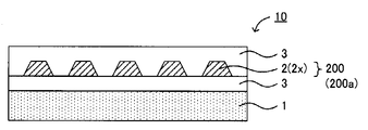
- FIG. 1 is a schematic cross-sectional view showing an example of a laminate of the present disclosure.
- the laminated body 10 of the present disclosure is a laminated body that has both the property of reflecting infrared rays A and the property of transmitting radio waves B.
- the laminated body 10 of this indication is a transparent laminated body normally. “Transparent” refers to the property of transmitting visible light.
- the visible light transmittance of the laminate 10 is, for example, 50% or more, preferably 70% or more, and more preferably 90% or more with respect to visible light having a wavelength of 380 nm or more and 780 nm or less.
- the laminated body 10 has the base material 1 and the metal layer 200 which is arrange
- FIG. the laminated body 10 includes the base material 1 and the metal layer 200 (first metal layer 200a) including the plurality of metal portions 2.
- arranged on the substrate means both the case where it is directly disposed on the substrate and the case where it is indirectly disposed on the substrate via another layer. Examples of the other layer include a dielectric layer described later.
- FIG. 2 is a schematic cross-sectional view illustrating an inclined metal portion in the present disclosure.
- the laminated body of the present disclosure includes an inclined metal portion 2 x as at least one of the plurality of metal portions 2.
- the inclined metal portion 2x usually includes a top surface portion 21 and a bottom portion 22 formed continuously from the top surface portion 21 and having a thickness smaller than that of the top surface portion 21.
- T MAX the maximum value of the thickness of the inclined metal portion 2x
- a portion having a thickness of 90% or more of T MAX is defined as a top surface portion.
- the top surface portion preferably has a flat portion at the center.
- the inclined metal portion 2 x has a tailing portion 22 that is formed continuously from the top surface portion 21 and has a smaller thickness than the top surface portion 21.
- the thickness usually decreases continuously or discontinuously from the boundary with the top surface portion 21 toward the opposite side.
- the “top surface portion” in the present disclosure does not necessarily mean only the vertically upper portion, and the position of the top surface portion varies depending on the arrangement state of the stacked body. For example, when the laminate is attached to a window glass, the “top surface portion” is a portion on the side surface side. In order to clarify this point, the “top surface portion” may be referred to as a “first region”.
- the “skirt” is sometimes referred to as a “second region”.
- the inclined metal portion 2x preferably has a first region 21 and a second region 22 whose thickness is continuously reduced from the first region 21.
- the laminated body which suppressed the glare by providing the inclination metal part which has a skirt part (second field).
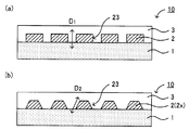
- the end 23 of the metal part 2 is formed perpendicular to the base material 1, and the direction D 1 of the end 23 is It was perpendicular to the plane of the substrate 1.
- the laminate 10 of the present disclosure the direction D 2 of the inclined metal section 2x end 23, not perpendicular to the plane of the substrate 1.
- the “glare” that occurred at the end portion 23 formed vertically as shown in FIG. 3A forms a skirt (second region) as shown in FIG. 3B. It is suppressed.
- Base material is a member that holds a metal layer and the like described later.
- the material of the base material is not particularly limited, and examples thereof include a resin.
- the resin include polyethylene, polypropylene, polyethylene terephthalate, polyethylene naphthalate, polybutylene terephthalate, polycarbonate, polyamide, polyimide, polyamideimide, polytetrafluoroethylene, tetrafluoroethylene / perfluoroalkyl vinyl ether copolymer, and the like. Of these, polyethylene terephthalate, polyethylene naphthalate, and polycarbonate are preferable.
- the thickness of the base material is, for example, 10 ⁇ m or more and 200 ⁇ m or less, and may be 20 ⁇ m or more and 100 ⁇ m or less. If the thickness of the substrate is too small, the handling property may be deteriorated when forming the metal layer or the dielectric layer. If the thickness of the substrate is too large, the visible light transmittance may be decreased. is there.
- the method for producing the substrate is not particularly limited, and examples thereof include a method of forming a film by melt-extrusion of a raw material resin into a film or solution extrusion. If necessary, the obtained film may be subjected to at least one of a stretching process, a heat setting process, and a heat relaxation process.
- the stretching process may be a process in the longitudinal direction, a process in the width direction, or a process in the longitudinal direction and the width direction.
- the metal layer in this indication is a layer which is arranged on a substrate and is constituted from a plurality of metal parts.
- the plurality of metal portions may be electrically independent or may not be electrically independent, but the former is preferable. This is because a decrease in radio wave permeability can be suppressed.
- at least one of the plurality of metal portions is an inclined metal portion. Details of the inclined metal portion will be described later.
- the material of the metal layer is not particularly limited, and examples thereof include metals such as Ag, Al, Cu, Pd, Au, Pt, Ni, Bi, Ge, and Ga, and alloys containing at least one of these metals. Can do. Among these, silver, silver alloy, aluminum, aluminum alloy, copper, and copper alloy are preferable. Since these have high free electron density, even if it is a thin film, high infrared reflectivity can be obtained.
- the shape of the metal part in plan view is not particularly limited, and examples thereof include a band shape, a dot shape, and a rectangular shape.
- Examples of the pattern shape composed of a plurality of metal portions include a stripe shape.
- variety of an adjacent metal part are 10 micrometers or more and 5 mm or less, respectively. If the width of the adjacent metal part is too small, the radio wave permeability may be reduced, and if the width of the adjacent metal part is too large, the infrared reflectivity may be reduced.
- the thickness of the metal layer is not particularly limited, but is, for example, 5 nm or more and 50 nm or less. If the thickness of the metal layer is too small, the infrared reflectivity may be reduced, and if the thickness of the metal layer is too large, the visible light transmittance may be reduced.
- the laminated body of the present disclosure may have a dielectric layer.
- the dielectric layer can improve the visible light transmittance due to the interference effect with the metal layer.
- the dielectric layer material preferably has a refractive index with respect to visible light of, for example, 1.4 or more. This is because a good interference effect can be obtained.
- the material for the dielectric layer include Ti, Zr, Hf, Nb, Zn, Al, Ga, In, Tl, Ga, Sn, Si and other metal oxides, and at least one of these metals Among them, TiO 2 , ZnO and SiO 2 are preferable.
- the location of the dielectric layer 3 is not particularly limited.
- the dielectric layer 3 may be disposed between the base material 1 and the metal layer 200 (first metal layer 200a), or may be disposed so as to cover the metal portion 2. good.
- the dielectric layer 3 is preferably disposed so as to fill the top surface portion of the metal portion 2 and the space of the adjacent metal portion 2.
- a dielectric layer may be disposed between the metal layers.
- the thickness of a dielectric material layer is 5 nm or more and 100 nm or less, for example.
- Laminate The laminate of the present disclosure has infrared reflectivity and radio wave transparency.
- the infrared reflectivity can be evaluated, for example, by measuring an average light reflectance at a wavelength of 1500 nm or more and 2200 nm or less.
- the average light reflectance is, for example, 60% or more, and preferably 70% or more.
- radio wave permeability can be evaluated, for example, by measuring radio wave transmittance at a frequency of 1 GHz.
- the radio wave transmittance is, for example, 80% or more, and preferably 95% or more.
- the laminate of the present disclosure includes an inclined metal part.
- the inclined metal portion 2 x is normally formed continuously from the top surface portion (first region) 21 and the top surface portion (first region) 21, and more than the top surface portion (first region) 21.
- a skirt (second region) 22 having a small thickness.
- the thickness usually decreases continuously or discontinuously from the boundary with the top surface portion (first region) 21 toward the opposite side. In particular, it is preferable that the thickness decreases continuously or discontinuously to zero.
- the inclined metal portion 2x preferably includes a top surface portion (first region) 21 and a tailing portion (second region) 22 having a thickness continuously reduced from the top surface portion (first region) 21.
- the width of the top surface portion (first region) 21 is preferably 10 ⁇ m or more and 5 mm or less, for example.
- the width of the skirt portion (second region) 22 is, for example, 0.1 ⁇ m or more, 0.2 ⁇ m or more, or 0.3 ⁇ m or more.
- the width of the skirt portion (second region) 22 is, for example, 5 mm or less.
- skirting portions (second regions) 22 are provided on both sides of the top surface portion (first region) 21. However, in the present disclosure, at least one side of the top surface portion (first region) 21 is provided.
- the skirting part (second region) 22 only needs to be provided.
- the laminate of the present disclosure includes an inclined metal part as at least one of the plurality of metal parts.
- the ratio of the inclined metal parts to all the metal parts is, for example, 50% or more, 70% or more, or 90% or more. Further, in one metal layer, all metal parts may be inclined metal parts.
- the laminate of the present disclosure may have one metal layer or two or more metal layers.
- first metal layer when the laminated body of the present disclosure has one metal layer, it may be referred to as a first metal layer, and when the laminated body of the present disclosure has two metal layers, they are referred to as the first metal layer and the first metal layer.
- first metal layer when the laminated body of the present disclosure has two metal layers, they are referred to as the first metal layer and the first metal layer.
- the metal part which comprises a 1st metal layer may be called a 1st metal part
- the metal part which comprises a 2nd metal layer may be called a 2nd metal part.
- first metal part when the first metal part is an inclined metal part, it may be referred to as a first inclined metal part, and when the second metal part is an inclined metal part, it may be referred to as a second inclined metal part. is there.
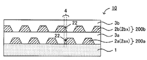
- the laminated body 10 of the present disclosure includes the first metal layer 200 a and the second metal layer 200 b as the metal layers, and the base material 1 and the first metal layer in the thickness direction.
- 200a and the second metal layer 200b are preferably arranged in this order. That is, it is preferable to have the second metal layer 200b on the surface opposite to the substrate 1 of the first metal layer 200a.
- the first dielectric layer 3a is disposed between the first metal layer 200a and the second metal layer 200b, and the second dielectric layer 3b is disposed so as to cover the surface of the second metal layer 200b. Has been.
- the skirt part (second region) is formed with an overlapping part overlapping the second metal part in plan view.
- the second metal part in the overlapping part may be an inclined metal part or not an inclined metal part, but the former is preferable.
- the bottom part (second region) overlaps the first metal part in plan view. This is because the occurrence of color unevenness due to overlapping portions can be suppressed.
- the first metal part in the overlapping part may be an inclined metal part or not an inclined metal part, but the former is preferable.
- the laminated body 10 of the present disclosure includes a bottom portion (second region) 22 in the first inclined metal portion 2ax of the first metal layer 200a and the second metal layer 200b. It is preferable to have the overlap part 4 with which the skirt part (2nd area
- FIG. 6A is a schematic cross-sectional view of a laminate including a metal portion that does not have a skirt portion (second region).
- the overlapping portion 4 is formed in which the first metal portion 2a and the second metal portion 2b overlap in plan view, but the total thickness of the metal portions in the overlap portion 4 is in plan view, This is the sum of the thickness of the first metal part 2a and the thickness of the second metal part 2b.
- the visible light transmittance of the overlapping portion 4 is reduced, and the color appears dark and color unevenness occurs.
- the overlapping portion 4 appears darker than the surroundings, and the visibility through the stacked body is reduced. Note that the AA cross-sectional view of FIG. 6B corresponds to FIG.
- FIG. 6C is a schematic cross-sectional view of a laminate including a metal part having a skirt part (second region).
- the 1st metal part 2a and the 2nd metal part 2b overlap in planar view is formed, the 1st metal part 2a and the 2nd metal part 2b are tailing parts ( Therefore, the total thickness of the metal parts in the overlapping part 4 is smaller than that in the case of FIG. As a result, a decrease in visible light transmittance of the overlapping portion 4 can be suppressed, and the occurrence of color unevenness can be suppressed.
- FIG. 6 (c) although the overlap part 4 in which the 1st metal part 2a and the 2nd metal part 2b overlap in planar view is formed, the 1st metal part 2a and the 2nd metal part 2b are tailing parts ( Therefore, the total thickness of the metal parts in the overlapping part 4 is smaller than that in the case of FIG. As a result, a decrease in visible light transmittance of the overlapping portion 4 can be suppressed,
- the overlapping portion 4 looks equivalent to the surroundings, and a reduction in visibility through the laminate can be suppressed.
- the use of the metal portion having the skirt portion (second region) has an advantage that a margin of alignment accuracy is increased when two or more metal layers are stacked. Note that the AA cross-sectional view of FIG. 6D corresponds to FIG.
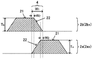
- the width of the overlapping portion of the first metal part and second metal part overlap in a plan view and W 1.
- the value of W 1 is, for example, 0.1 ⁇ m or more, may also be 0.2 ⁇ m or more, may be 0.3 ⁇ m or more.
- the value of W 1 is, for example, 5mm or less.
- the width of the top wall in the overlapping portion (first region) and W For example, as shown in FIG. 7, the top wall in the overlapping portion 4 the width of the (first region) 21 and W 2.
- the width of the top surface portion (first region) in the overlapping portion refers to each top surface portion (first region). ) 21 width.
- the value of W 2 is, for example, 120 ⁇ m or less, and preferably 100 ⁇ m or less. Since the resolution limit of the human eye is 100 ⁇ m, if the value of W 2 is 100 ⁇ m or less, the human eye cannot recognize the overlapping portion. For this reason, when the value of W 2 is 100 ⁇ m or less, it is possible to suppress a decrease in visibility. On the other hand, the value of W 2 may be 0. That is, the top surface portion (first region) may not exist in the overlapping portion.
- TSUM be the total thickness of the first metal part and the second metal part in the overlapping part.
- T 1 of the first metal part 2a (first inclined metal part 2ax) at the position ⁇ of the overlapping part 4 and the second metal part 2b (first the sum of the thickness T 2 of the two inclined metal section 2bx) and T sUM the thickness of the first metal part 2a (first inclined metal part 2ax) at the position ⁇ of the overlapping part 4 and the second metal part 2b (first the sum of the thickness T 2 of the two inclined metal section 2bx) and T sUM.
- the minimum value is preferably 5 nm or more, for example. When the minimum value of T SUM is too small, there is a case where the infrared reflective property is lowered.
- the maximum value of T SUM is the thickness T a of the first metal portion 2 a or the second value. greater than the thickness T b of the metal part 2b.
- Maximum value of T SUM is preferably T sum of a and T b (T a + T b) less than for (T a + T b), for example, preferably 0.8 times or less, It is preferable that it is 0.6 times or less.
- the first metal part 2a and the second metal part 2b have the same cross-sectional shape, but the first metal part 2a and the second metal part 2b are different from each other. It may have a cross-sectional shape.
- the first metal portion 2a and the second metal portion 2b are both inclined metal portions 2x, but the shape of the skirt portion (second region) 22 is different from each other, and the overlapping portion 4 There is one top surface portion (first region).
- the first metal portion 2a is not a tilted metal portion, and the end portion 23 is a conventional metal portion perpendicular to the base material, but the second metal portion 2b is a tilted metal portion 2x. It is.
- the 1st metal part 2a may be the inclination metal part 2x
- the 2nd metal part 2b may be a conventional metal part.
- the laminated body of this indication has a 1st metal layer and a 2nd metal layer, it is preferable that the ratio of the transparent area
- the effective area of the laminate refers to an area where the laminate exhibits radio wave transparency and infrared reflectivity in plan view.
- the region is determined based on the first metal layer or the second metal layer located on the outermost side in plan view.
- the transparent region refers to a region in the effective region of the laminate in which neither the first metal layer nor the second metal layer exists in plan view.
- region of a laminated body is 10% or less, for example, it is preferable that it is 5% or less, and it is more preferable that it is 1% or less.
- the 1st metal part and the 2nd metal part are alternately arrange
- the laminated body 10 of this indication has the 1st metal layer 200a and the 2nd metal layer 200b as a metal layer, and the 1st metal layer 200a, The base material 1 and the second metal layer 200b may be arranged in this order.
- the first dielectric layer 3a is disposed so as to cover the surface of the first metal layer 200a
- the second dielectric layer 3b is disposed so as to cover the surface of the second metal layer 200b.
- the laminated body 10 of this indication has the 1st base material 1a and the 1st member which has the 1st metal layer 200a arrange
- the first dielectric layer 3a disposed so as to cover the surface of the first metal layer 200a and the first dielectric layer 3a disposed so as to cover the surface of the second metal layer 200b.
- the laminated body 10 has the 1st base material 1a, the 1st metal layer 200a, the contact bonding layer 5, the 2nd metal layer 200b, and the 2nd base material 1b in this order.
- the thickness of the laminate of the present disclosure is not particularly limited, but is, for example, 1 mm or less, and may be 500 ⁇ m or less.
- the laminated body of this indication is a film form.
- the laminated body of this indication can be used for the arbitrary uses which require radio wave permeability and infrared reflectivity.
- An example of the closing member is a window member.
- the structure has a conductive casing
- radio waves enter and exit through the closing member, and thus the laminate of the present disclosure is particularly effective.
- Examples of the structure having a conductive casing include an automobile and a train.
- it is effective to use the laminate of the present disclosure for a windshield of an automobile or a train.
- FIG. 11 is a schematic cross-sectional view illustrating an example of a manufacturing method of the laminate of the present disclosure.
- the base material 1 is prepared (FIG. 11 (a)).
- a metal layer 200 composed of a plurality of metal parts 2 is formed by vapor deposition using the mask 11 (FIG. 11B).
- the first metal layer 200a including the plurality of metal portions 2 is formed.
- the metal wraps around the gap C during film formation, and the top surface portion (first region) 21 and the skirt portion ( The inclined metal portion 2x having the second region 22 is obtained (FIG. 11C).
- the dielectric layer 3 is formed so as to cover the metal part 2 (FIG. 11D). Thereby, the laminated body of this indication is obtained.
- the present disclosure it is possible to obtain a laminated body having an inclined metal portion by providing a gap between the mask and the deposition object. Moreover, in this indication, the mask in which the predetermined pattern was drawn is installed between a vapor deposition source and a vapor deposition target object, and vapor deposition is performed. Therefore, film formation and patterning can be performed at the same time, and further, the inclined metal portion can be formed by providing the gap.
- the manufacturing method of the laminated body of this indication is demonstrated for every process.
- the metal layer formation process in this indication is a process of forming a metal layer by the evaporation method using a mask.
- the process of forming a 1st metal layer with the vapor deposition method using a mask may be called a 1st metal layer formation process.
- the inclined metal part is formed as at least one of the plurality of metal parts by providing a gap between the mask and the deposition object. For example, when forming a metal film directly on a base material, a base material turns into a vapor deposition object. Further, for example, when a metal film is formed on a base material via a dielectric layer, the base material and the dielectric layer become vapor deposition objects.
- the shape of the inclined metal part, in particular, the width of the bottom part (second region) can be controlled, for example, by appropriately selecting the gap between the mask and the deposition object.
- the gap between the mask and the vapor deposition object is, for example, 50 ⁇ m or more, 200 ⁇ m or more, or 500 ⁇ m or more.
- the gap between the mask and the vapor deposition object is, for example, 50 mm or less.
- the width of the skirt portion (second region) is also affected by the degree of vacuum during film formation. The width of the skirt (second region) tends to be smaller as the degree of vacuum during film formation is higher, and the width of the skirt (second region) is larger as the degree of vacuum during film formation is lower. There is a tendency.
- the inclined metal part is usually formed by providing a gap between the mask and the vapor deposition object.
- the formation of the inclined metal part may be accelerated so that the inclined metal part can be easily obtained.
- the formation promotion process of the inclined metal part as shown in FIGS. 12A and 12B, at least one of the mask 11 and the base material 1 which is a deposition target is swung during film formation. Processing. Examples of the swinging direction include the width direction of the roll.
- FIG. 12B is a cross-sectional view taken along the line AA in FIG.
- FIGS. 12A and 12B is a cross-sectional view taken along the line AA in FIG.
- the mask 11 is provided with a protruding part 12 for reducing the amount of deposited metal, thereby forming a film.
- a process of swinging the mask 11 is mentioned. Examples of the swinging direction include the traveling direction of the roll.
- FIG. 12D is a cross-sectional view taken along the line AA in FIG.
- the shape of the mask may be devised so that the inclined metal portion can be easily obtained.
- the inclined metal part 2x is easily obtained.
- a plurality of vapor deposition sources may be used so that the inclined metal portion can be easily obtained.
- FIG. 14 by providing a plurality of vapor deposition sources 13 and performing vapor deposition from a plurality of angles, an inclined metal portion can be easily obtained.
- the method for manufacturing a laminate according to the present disclosure may include a dielectric layer forming step for forming a dielectric layer as necessary.
- the place where the dielectric layer is formed is not particularly limited, and the dielectric layer 3 may be formed between the base material 1 and the metal layer 200 (first metal layer 200a) as shown in FIG.
- the dielectric layer 3 may be formed so as to cover.
- a dielectric layer may be formed between the metal layers.
- a dielectric layer may be formed between the first metal layer and the second metal layer.
- the method for forming the dielectric layer is not particularly limited, and examples thereof include dry processes such as sputtering, vacuum deposition, CVD, and electron beam deposition. Note that if the formation of the metal layer and the formation of the dielectric layer are both dry processes, there is an advantage that the metal layer and the dielectric layer can be formed in-line. That is, it is preferable that the metal layer forming step (for example, the first metal layer forming step) and the dielectric layer forming step are continuously performed. As a method for continuously performing the metal layer forming step and the dielectric layer forming step, for example, a Roll-to-Roll method can be exemplified. Further, when two or more metal layers are formed, for example, a plurality of metal layer forming steps and dielectric layer forming steps may be repeated.
- dry processes such as sputtering, vacuum deposition, CVD, and electron beam deposition.
- the chamber was evacuated until the pressure in the chamber became 2.0 ⁇ 10 ⁇ 3 Pa or less, and 25 sccm of Ar was introduced as a discharge gas. Thereafter, the pressure in the chamber was adjusted to 0.4 Pa, and the discharge current was set to 0.2 A using a direct current sputtering method. At this time, the substrate (PET film) temperature was room temperature. Thereby, the metal layer (Ag layer) which has a stripe-like inclination metal part on PET was formed into a film.
- the target was changed to Ti, and the chamber was evacuated until the pressure in the chamber became 2.0 ⁇ 10 ⁇ 3 Pa or less, Ar was introduced at 10 sccm, O 2 was introduced at 5 sccm, and the total flow rate was 15 sccm. Thereafter, the pressure in the chamber was adjusted to 0.4 Pa, and the discharge current was set to 0.3 A using a direct current sputtering method. At this time, the substrate (PET film) temperature was room temperature. Thereby, TiO 2 was formed on the Ag layer. Thereby, the laminated body (film) which has a stripe-shaped inclination metal part was obtained.
- Example 1 A laminate was obtained in the same manner as in Example 1 except that the metal layer was formed by closely attaching the vapor deposition mask and the vapor deposition target. The obtained laminated body did not have an inclined metal part.
- Example 1 Using the laminates obtained in Example 1 and Comparative Example 1, the glare property was evaluated. Specifically, the observer observed each sample in a state 30 cm away from the sample, and evaluated the degree of glare. In the evaluation, a sample with little glare was rated as “ ⁇ ”, a sample with severe glare was marked as “X”, and a sample having an intermediate level was marked as “ ⁇ ”. The results are shown in Table 1.
- Example 2 On the TiO 2 surface side of the sample obtained in Example 1, a metal layer (Ag layer) having a stripe-shaped inclined metal part and a dielectric layer (TiO 2 ) under the same film forming conditions as in Example 1. The layers were laminated. When laminating the second Ag layer, the deposition mask is shifted in a direction perpendicular to the direction in which the stripe extends by 150 ⁇ m, and the first and second inclined metal parts are When observed from the cross-sectional direction, the position was adjusted to be shifted. Thereby, the laminated body which has a 1st metal layer and a 2nd metal layer was obtained. The metal parts constituting the first metal layer and the second metal layer were both striped inclined metal parts. The width of the top wall in the overlapping portion (first region) (W 2 shown in FIG. 7) was also two places 0 .mu.m.
- Example 3 A laminate was obtained in the same manner as in Example 2 except that the width (W 2 shown in FIG. 7) of the top surface portion (first region) in the overlapping portion was 75 ⁇ m at both locations.
- Example 4 A laminate was obtained in the same manner as in Example 2 except that the width (W 2 shown in FIG. 7) of the top surface portion (first region) in the overlapping portion was 120 ⁇ m at both locations.
- Example 2 A laminated body was obtained in the same manner as in Example 1 except that the vapor deposition mask and the vapor deposition target were brought into close contact to form the first metal layer and the second metal layer. The obtained laminated body did not have an inclined metal part.
- Evaluation of infrared reflectance was performed by obtaining an average light reflectance at a wavelength of 1500 nm or more and 2200 nm or less. Specifically, it was measured using an ultraviolet-visible near-infrared spectrophotometer V-7200 (Japanese sentence structure). Evaluation of radio wave permeability was performed by obtaining radio wave permeability at a frequency of 1 GHz. Specifically, it was measured by the KEC method using an electromagnetic wave shielding effect evaluator TSES-KEC (manufactured by Techno Science Japan). The results are shown in Table 2.
Landscapes
- Physics & Mathematics (AREA)
- General Physics & Mathematics (AREA)
- Optics & Photonics (AREA)
- Health & Medical Sciences (AREA)
- Toxicology (AREA)
- Chemical & Material Sciences (AREA)
- Life Sciences & Earth Sciences (AREA)
- Chemical Kinetics & Catalysis (AREA)
- General Chemical & Material Sciences (AREA)
- Geochemistry & Mineralogy (AREA)
- Materials Engineering (AREA)
- Organic Chemistry (AREA)
- Engineering & Computer Science (AREA)
- Spectroscopy & Molecular Physics (AREA)
- Laminated Bodies (AREA)
- Optical Filters (AREA)
- Physical Vapour Deposition (AREA)
Abstract
電波透過性および赤外線反射性を有し、基材、および、複数の金属部を含む第一金属層を有する積層体であって、 前記第一金属層の前記複数の金属部の少なくとも一つとして、第一領域と、前記第一領域から連続的に厚さが減少した第二領域と、を有する第一傾斜金属部を備える、積層体。
Description
本開示は、ぎらつきを抑制した電波透過性赤外線反射積層体に関する。
赤外線を反射しつつも、電波を透過する積層体が知られている。例えば、特許文献1には、透明導電膜を含む自動車ガラス用積層体であって、透明導電膜が、パターン部と、該パターン部を取り囲むギャップ部とを有し、ギャップ部に、特定の屈折率を有する充填材が充填されている自動車ガラス用積層体が開示されている。この技術は、透明導電膜のパターンの「ぎらつき」を抑制することを目的としている。
また、特許文献2には、少なくとも基材と、複数の不連続に配置されている金属膜を有する2層以上の不連続金属層とを有し、該不連続金属層の少なくとも1層の該不連続に配置されている金属膜の一部と、該金属膜を有さない開口部の一部とが、他方の不連続金属層の金属膜を覆う構成である熱線遮断用基材が開示されている。この技術は、高い可視光透過性、近赤外から中赤外領域にかけての高い熱線反射性(熱線遮断性)、及び高い電磁波透過性を有する熱線遮断用基材を提供することを目的としている。
特許文献1では、透明導電膜のパターンのギャップ部に、特定の屈折率を有する充填材を充填することにより、ぎらつきを抑制している。しかしながら、充填材を用いるため製造コストが上昇する。さらに、充填材を配置する工程が必要になるため、工程数も増加する。
本開示は、上記実情に鑑みてなされたものであり、簡便な手段により、ぎらつきを抑制した電波透過性赤外線反射積層体を提供することを主目的とする。なお、本開示においては、電波透過性赤外線反射積層体を、単に「積層体」と称する場合がある。
上記課題を解決するために、本開示においては、電波透過性および赤外線反射性を有し、基材、および、複数の金属部を含む第一金属層を有する積層体であって、上記第一金属層の上記複数の金属部の少なくとも一つとして、第一領域と、上記第一領域から連続的に厚さが減少した第二領域と、を有する第一傾斜金属部を備える、積層体を提供する。
また、本開示においては、電波透過性および赤外線反射性を有し、基材、および、複数の金属部を含む第一金属層を有する積層体の製造方法であって、マスクを用いた蒸着法により、上記第一金属層を形成する第一金属層形成工程を有し、上記第一金属層形成工程において、上記マスクおよび蒸着対象物の間に隙間を設けることにより、上記第一金属層の上記複数の金属部の少なくとも一つとして、第一領域と、上記第一領域から連続的に厚さが減少した第二領域と、を有する第一傾斜金属部を形成することを特徴とする積層体の製造方法を提供する。
本開示においては、電波透過性および赤外線反射性を有し、基材と、上記基材上に配置され、複数の金属部から構成される金属層と、を有する積層体であって、上記複数の金属部の少なくとも一つとして、頂面部と、上記頂面部から連続的に形成され、上記頂面部よりも厚さが小さい裾引き部と、を有する傾斜金属部を備えることを特徴とする積層体を提供する。
本開示によれば、裾引き部を有する傾斜金属部を設けることで、ぎらつきを抑制した積層体とすることができる。
上記開示においては、上記裾引き部の幅が、0.1μm以上であることが好ましい。
上記開示においては、上記金属層が、第一金属層および第二金属層を有し、厚さ方向において、上記基材、上記第一金属層、上記第二金属層が、この順に配置されていることが好ましい。
上記開示においては、上記第一金属層および上記第二金属層が、上記傾斜金属部として、それぞれ、第一傾斜金属部および第二傾斜金属部を有し、上記第一傾斜金属部における上記裾引き部と、上記第二傾斜金属部における上記裾引き部とが平面視上重複する重複部を有することが好ましい。
上記開示においては、上記重複部における上記頂面部の幅が、100μm以下であることが好ましい。
上記開示においては、上記重複部における上記第一傾斜金属部および上記第二傾斜金属部の合計厚さの最小値が、5nm以上であることが好ましい。
また、本開示においては、電波透過性および赤外線反射性を有し、基材と、上記基材上に配置され、複数の金属部から構成される金属層と、を有する積層体の製造方法であって、マスクを用いた蒸着法により、上記金属層を形成する金属層形成工程を有し、上記金属層形成工程において、上記マスクおよび蒸着対象物の間に隙間を設けることにより、上記複数の金属部の少なくとも一つとして、頂面部と、上記頂面部から連続的に形成され、上記頂面部よりも厚さが小さい裾引き部と、を有する傾斜金属部を形成することを特徴とする積層体の製造方法を提供する。
本開示によれば、マスクと蒸着対象物との間に隙間を設けることにより、傾斜金属部を有する積層体を得ることができる。
本開示においては、ぎらつきを抑制した電波透過性赤外線反射積層体を提供することができるという効果を奏する。
以下、本開示の積層体、および、積層体の製造方法について、詳細に説明する。
A.積層体
図1は、本開示の積層体の一例を示す概略断面図である。図1に示すように、本開示の積層体10は、赤外線Aを反射する性質と、電波Bを透過する性質とを兼ね備えた積層体である。また、本開示の積層体10は、通常、透明な積層体である。「透明」とは、可視光線を透過する性質をいう。積層体10の可視光線透過率は、波長380nm以上780nm以下の可視光線に対して、例えば50%以上であり、70%以上であることが好ましく、90%以上であることがより好ましい。また、積層体10は、基材1と、基材1上に配置され、複数の金属部2から構成される金属層200と、を有する。言い換えると、積層体10は、基材1と、複数の金属部2を含む金属層200(第一金属層200a)とを有する。なお、本開示において、「基材上に配置され」とは、基材に直接配置された場合、および、基材に他の層を介して間接的に配置された場合の両方をいう。他の層としては、例えば、後述する誘電体層を挙げることができる。
図1は、本開示の積層体の一例を示す概略断面図である。図1に示すように、本開示の積層体10は、赤外線Aを反射する性質と、電波Bを透過する性質とを兼ね備えた積層体である。また、本開示の積層体10は、通常、透明な積層体である。「透明」とは、可視光線を透過する性質をいう。積層体10の可視光線透過率は、波長380nm以上780nm以下の可視光線に対して、例えば50%以上であり、70%以上であることが好ましく、90%以上であることがより好ましい。また、積層体10は、基材1と、基材1上に配置され、複数の金属部2から構成される金属層200と、を有する。言い換えると、積層体10は、基材1と、複数の金属部2を含む金属層200(第一金属層200a)とを有する。なお、本開示において、「基材上に配置され」とは、基材に直接配置された場合、および、基材に他の層を介して間接的に配置された場合の両方をいう。他の層としては、例えば、後述する誘電体層を挙げることができる。
図2は、本開示における傾斜金属部を説明する概略断面図である。図2に示すように、本開示の積層体は、複数の金属部2の少なくとも一つとして、傾斜金属部2xを備える。傾斜金属部2xは、通常、頂面部21と、頂面部21から連続的に形成され、頂面部21よりも厚さが小さい裾引き部22と、を有する。ここで、傾斜金属部2xの厚さの最大値をTMAXとした場合、TMAXの90%以上の厚さを有する部分を、頂面部と定義する。特に、頂面部は、中央に平坦部を有することが好ましい。一方、傾斜金属部2xは、頂面部21から連続的に形成され、頂面部21よりも厚さが小さい裾引き部22を有する。裾引き部22では、通常、頂面部21との境界から、その反対に向けて、厚さが連続的または不連続的に減少する。なお、本開示における「頂面部」は、当然、鉛直上側の部位のみを意味する訳ではなく、積層体の配置状態によって頂面部の位置は変化する。例えば、積層体を窓ガラスに貼付した場合には、「頂面部」は側面側の部位となる。この点を明確化するために、「頂面部」を「第一領域」と称する場合がある。これに伴い、「裾引き部」を「第二領域」と称する場合がある。傾斜金属部2xは、第一領域21と、第一領域21から連続的に厚さが減少した第二領域22とを有することが好ましい。
本開示によれば、裾引き部(第二領域)を有する傾斜金属部を設けることで、ぎらつきを抑制した積層体とすることができる。ここで、図3(a)に示すように、従来の積層体10は、金属部2の端部23が基材1に対して垂直に形成されており、端部23の方向D1は、基材1の平面に対して垂直であった。これに対して、図3(b)に示すように、本開示の積層体10は、傾斜金属部2xの端部23の方向D2が、基材1の平面に対して垂直にならない。その結果、図3(a)のように垂直に成形された端部23で起こっていた「ぎらつき」が、図3(b)のように裾引き部(第二領域)を形成することで抑制される。具体的には、平面視において、端部23の「線」で反射されていたものが、アスペクト比が大きい裾引き部(第二領域)の「面」で反射されることで、反射光を分散することができる。その結果、金属部の端部に起因する「ぎらつき」を抑制できると考えられる。また、裾引き部(第二領域)を形成すると、平面視した場合、金属部がある部分と金属部がない部分との境目で金属部から構成されるパターンの際立ちを抑えることにもなり、金属部から構成されるパターン形状を視認しにくくなることも期待できる。
以下、本開示の積層体について、構成ごとに説明する。
以下、本開示の積層体について、構成ごとに説明する。
1.基材
本開示における基材は、後述する金属層等を保持する部材である。基材の材料は特に限定されないが、例えば、樹脂を挙げることができる。樹脂としては、例えば、ポリエチレン、ポリプロピレン、ポリエチレンテレフタレート、ポリエチレンナフタレート、ポリブチレンテレフタレート、ポリカーボネート、ポリアミド、ポリイミド、ポリアミドイミド、ポリテトラフルオロエチレン、テトラフルオロエチレン・パーフルオロアルキルビニルエーテル共重合体等が挙げられ、中でも、ポリエチレンテレフタレート、ポリエチレンナフタレート、ポリカーボネートが好ましい。
本開示における基材は、後述する金属層等を保持する部材である。基材の材料は特に限定されないが、例えば、樹脂を挙げることができる。樹脂としては、例えば、ポリエチレン、ポリプロピレン、ポリエチレンテレフタレート、ポリエチレンナフタレート、ポリブチレンテレフタレート、ポリカーボネート、ポリアミド、ポリイミド、ポリアミドイミド、ポリテトラフルオロエチレン、テトラフルオロエチレン・パーフルオロアルキルビニルエーテル共重合体等が挙げられ、中でも、ポリエチレンテレフタレート、ポリエチレンナフタレート、ポリカーボネートが好ましい。
基材の厚さは、例えば、10μm以上200μm以下であり、20μm以上100μm以下であっても良い。基材の厚さが小さすぎると、金属層または誘電体層を形成する際に、ハンドリング性が悪化する場合があり、基材の厚さが大きすぎると、可視光線透過率が低下する場合がある。
基材の製造方法は特に限定されないが、例えば、原料の樹脂をフィルム状に溶融押出しするか、溶液押出しすることで、フィルム状に成形する方法を挙げることができる。得られたフィルムに対して、必要に応じて、延伸処理、熱固定処理、および、熱弛緩処理の少なくとも一つの処理を行っても良い。また、延伸処理は、長手方向の処理であっても良く、幅方向の処理であっても良く、長手方向および幅方向の処理であっても良い。
2.金属層
本開示における金属層は、基材上に配置され、複数の金属部から構成される層である。また、複数の金属部は、それぞれ、電気的に独立していても良く、電気的に独立していなくても良いが、前者が好ましい。電波透過性の低下を抑制できるからである。また、本開示においては、複数の金属部の少なくとも一つが、傾斜金属部であることを特徴とする。傾斜金属部の詳細については後述する。
本開示における金属層は、基材上に配置され、複数の金属部から構成される層である。また、複数の金属部は、それぞれ、電気的に独立していても良く、電気的に独立していなくても良いが、前者が好ましい。電波透過性の低下を抑制できるからである。また、本開示においては、複数の金属部の少なくとも一つが、傾斜金属部であることを特徴とする。傾斜金属部の詳細については後述する。
金属層の材料は特に限定されないが、例えば、Ag、Al、Cu、Pd、Au、Pt、Ni、Bi、Ge、Ga等の金属、および、これらの金属の少なくとも一種を含有する合金を挙げることができる。中でも、銀、銀合金、アルミニウム、アルミニウム合金、銅、銅合金が好ましい。これらは、高い自由電子密度を有するため、薄膜であっても、高い赤外線反射性を得ることができる。
金属部の平面視形状は特に限定されないが、例えば、帯状、ドット状、矩形状等を挙げることができる。複数の金属部から構成されるパターン形状としては、例えば、ストライプ状を挙げることができる。また、金属部の幅、および、隣り合う金属部の幅は、それぞれ、10μm以上5mm以下であることが好ましい。隣り合う金属部の幅が小さすぎると、電波透過性が低下する場合があり、隣り合う金属部の幅が大きすぎると、赤外線反射性が低下する場合がある。
金属層の厚さは特に限定されないが、例えば、5nm以上50nm以下である。金属層の厚さが小さすぎると、赤外線反射性が低下する場合があり、金属層の厚さが大きすぎると、可視光線透過率が低下する場合がある。
3.誘電体層
本開示の積層体は、誘電体層を有していても良い。誘電体層は金属層との干渉効果により、可視光線透過率を向上させることができる。誘電体層の材料は、可視光線に対する屈折率が、例えば1.4以上であることが好ましい。良好な干渉効果が得られるからである。誘電体層の材料としては、例えば、Ti、Zr、Hf、Nb、Zn、Al、Ga、In、Tl、Ga、Sn、Si等の金属の酸化物、および、これらの金属の少なくとも一種を含有する複合酸化物を挙げることができ、中でも、TiO2、ZnOおよびSiO2が好ましい。
本開示の積層体は、誘電体層を有していても良い。誘電体層は金属層との干渉効果により、可視光線透過率を向上させることができる。誘電体層の材料は、可視光線に対する屈折率が、例えば1.4以上であることが好ましい。良好な干渉効果が得られるからである。誘電体層の材料としては、例えば、Ti、Zr、Hf、Nb、Zn、Al、Ga、In、Tl、Ga、Sn、Si等の金属の酸化物、および、これらの金属の少なくとも一種を含有する複合酸化物を挙げることができ、中でも、TiO2、ZnOおよびSiO2が好ましい。
誘電体層3の配置場所は特に限定されない。例えば図4に示すように、誘電体層3が、基材1および金属層200(第一金属層200a)の間に配置されていても良く、金属部2を覆うように配置されていても良い。後者の場合、金属部2の頂面部と、隣り合う金属部2の空間とを埋めるように、誘電体層3が配置されることが好ましい。また、後述するように、金属層が2層以上存在する場合には、各金属層の間に誘電体層が配置されていても良い。また、誘電体層の厚さは、例えば5nm以上100nm以下であることが好ましい。
4.積層体
本開示の積層体は、赤外線反射性および電波透過性を有する。赤外線反射性は、例えば、波長1500nm以上2200nm以下における平均光線反射率を測定することにより、評価することができる。平均光線反射率は、例えば、60%以上であり、70%以上であることが好ましい。一方、電波透過性は、例えば、周波数1GHzの電波透過率を測定することにより、評価することができる。電波透過率は、例えば、80%以上であり、95%以上であることが好ましい。
本開示の積層体は、赤外線反射性および電波透過性を有する。赤外線反射性は、例えば、波長1500nm以上2200nm以下における平均光線反射率を測定することにより、評価することができる。平均光線反射率は、例えば、60%以上であり、70%以上であることが好ましい。一方、電波透過性は、例えば、周波数1GHzの電波透過率を測定することにより、評価することができる。電波透過率は、例えば、80%以上であり、95%以上であることが好ましい。
本開示の積層体は、傾斜金属部を備える。図2に示すように、傾斜金属部2xは、通常、頂面部(第一領域)21と、頂面部(第一領域)21から連続的に形成され、頂面部(第一領域)21よりも厚さが小さい裾引き部(第二領域)22と、を有する。裾引き部(第二領域)22では、通常、頂面部(第一領域)21との境界から、その反対に向けて、厚さが連続的または不連続的に減少する。特に、厚さが連続的または不連続的に0まで減少することが好ましい。傾斜金属部2xは、頂面部(第一領域)21と、頂面部(第一領域)21から連続的に厚さが減少した裾引き部(第二領域)22とを有することが好ましい。頂面部(第一領域)21の幅は、例えば10μm以上5mm以下であることが好ましい。裾引き部(第二領域)22の幅は、例えば0.1μm以上であり、0.2μm以上であっても良く、0.3μm以上であっても良い。一方、裾引き部(第二領域)22の幅は、例えば5mm以下である。なお、図2では、頂面部(第一領域)21の両側に裾引き部(第二領域)22が設けられているが、本開示においては、頂面部(第一領域)21の少なくとも片側に裾引き部(第二領域)22が設けられていれば良い。
本開示の積層体は、複数の金属部の少なくとも一つとして、傾斜金属部を備える。一つの金属層において、全ての金属部に対する傾斜金属部の割合は、例えば50%以上であり、70%以上であっても良く、90%以上であっても良い。また、一つの金属層において、全ての金属部が傾斜金属部であっても良い。
本開示の積層体は、金属層を1層有していても良く、2層以上有していても良い。例えば、本開示の積層体が金属層を1層有する場合、それを第一金属層と称する場合があり、本開示の積層体が金属層を2層有する場合、それらを第一金属層および第二金属層と称する場合がある。また、第一金属層を構成する金属部を、第一金属部と称する場合があり、第二金属層を構成する金属部を、第二金属部と称する場合がある。また、第一金属部が傾斜金属部である場合、それを第一傾斜金属部と称する場合があり、第二金属部が傾斜金属部である場合、それを第二傾斜金属部と称する場合がある。
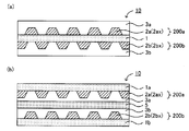
ここで、図5に示すように、本開示の積層体10は、金属層として、第一金属層200aおよび第二金属層200bを有し、厚さ方向において、基材1、第一金属層200a、第二金属層200bがこの順に配置されていることが好ましい。すなわち、第一金属層200aの基板1とは反対の面側に第二金属層200bを有することが好ましい。なお、図5において、第一金属層200aおよび第二金属層200bの間には第一誘電体層3aが配置され、第二金属層200bの表面を覆うように第二誘電体層3bが配置されている。
また、第一金属部が傾斜金属部を有する場合、その裾引き部(第二領域)が、第二金属部と平面視上重複する重複部が形成されていることが好ましい。重複部に起因する色ムラの発生を抑制できるからである。この場合、重複部における第二金属部は、傾斜金属部であっても良く、傾斜金属部でなくても良いが、前者が好ましい。同様に、第二金属部が傾斜金属部を有する場合、その裾引き部(第二領域)が、第一金属部と平面視上重複していることが好ましい。重複部に起因する色ムラの発生を抑制できるからである。この場合、重複部における第一金属部は、傾斜金属部であっても良く、傾斜金属部でなくても良いが、前者が好ましい。
特に、第一金属部および第二金属部の両方が傾斜金属部を有する場合、それらの裾引き部(第二領域)が平面視上重複していることが好ましい。具体的には、図5に示すように、本開示の積層体10が、第一金属層200aの第一傾斜金属部2axにおける裾引き部(第二領域)22と、第二金属層200bの第二傾斜金属部2bxにおける裾引き部(第二領域)22とが平面視上重複する重複部4を有することが好ましい。重複部に起因する色ムラの発生を抑制できる効果について、図6を用いて説明する。
図6(a)は、裾引き部(第二領域)を有しない金属部を備える積層体の概略断面図である。図6(a)では、第一金属部2aおよび第二金属部2bが平面視上重複する重複部4が形成されているが、重複部4における金属部の合計厚さが、平面視上、第一金属部2aの厚さと、第二金属部2bの厚さとの和になる。その結果、重複部4の可視光線透過率が低下し、色が濃く見え色ムラが生じる。具体的には、図6(b)に示すように、重複部4が周囲に比べて濃く見え、積層体を介した視認性を低下させる。なお、図6(b)のA-A断面図が、図6(a)に該当する。
一方、図6(c)は、裾引き部(第二領域)を有する金属部を備える積層体の概略断面図である。図6(c)では、第一金属部2aおよび第二金属部2bが平面視上重複する重複部4が形成されているが、第一金属部2aおよび第二金属部2bが裾引き部(第二領域)を有するため、重複部4における金属部の合計厚さが、図6(a)の場合に比べて小さくなる。その結果、重複部4の可視光線透過率の低下を抑制でき、色ムラの発生を抑制できる。具体的には、図6(d)に示すように、重複部4が周囲と同等に見え、積層体を介した視認性の低下を抑制できる。また、裾引き部(第二領域)を有する金属部を用いることで、金属層を2層以上積層する際に、位置あわせ精度のマージンが大きくなるという利点もある。なお、図6(d)のA-A断面図が、図6(c)に該当する。
また、第一金属部および第二金属部が平面視上重複する重複部の幅をW1とする。例えば図7に示すように、第一金属部2aおよび第二金属部2bが平面視上重複する重複部4の幅をW1とする。W1の値は、例えば0.1μm以上であり、0.2μm以上であっても良く、0.3μm以上であっても良い。一方、W1の値は、例えば、5mm以下である。
また、重複部における頂面部(第一領域)の幅をW2とする。例えば図7に示すように、重複部4における頂面部(第一領域)21の幅をW2とする。なお、図7では、重複部4における頂面部(第一領域)21が2箇所存在するが、「重複部における頂面部(第一領域)の幅」とは、各々の頂面部(第一領域)21の幅をいう。W2の値は、例えば120μm以下であり、100μm以下であることが好ましい。人間の目の解像限界は100μmであるため、W2の値が100μm以下になると、人間の目には重複部を認識できない。そのため、W2の値が100μm以下になると、視認性の低下を抑制できる。一方、W2の値は0であっても良い。すなわち、重複部に頂面部(第一領域)が存在しなくても良い。
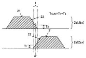
また、重複部における第一金属部および第二金属部の合計厚さをTSUMとする。例えば図8に示すように、重複部4の位置αにおける第一金属部2a(第一傾斜金属部2ax)の厚さT1、および、重複部4の位置αにおける第二金属部2b(第二傾斜金属部2bx)の厚さT2の和をTSUMとする。TSUMの値は、重複部における厚さの測定位置によって異なるが、その最小値は、例えば5nm以上であることが好ましい。TSUMの最小値が小さすぎると、赤外線反射性が低下する場合があるからである。
一方、上述した図7に示すように、重複部4に頂面部(第一領域)21が存在する場合、TSUMの最大値は、第一金属部2aの厚さTa、または、第二金属部2bの厚さTbよりも大きくなる。TSUMの最大値は、TaおよびTbの合計(Ta+Tb)よりも小さいことが好ましく、(Ta+Tb)に対して、例えば、0.8倍以下であることが好ましく、0.6倍以下であることが好ましい。
また、上述した図7、図8においては、第一金属部2aおよび第二金属部2bが、同じ断面形状を有しているが、第一金属部2aおよび第二金属部2bは、互いに異なる断面形状を有していても良い。例えば、図9(a)では、第一金属部2aおよび第二金属部2bは、ともに傾斜金属部2xであるが、裾引き部(第二領域)22の形状が互いに異なり、重複部4に存在する頂面部(第一領域)は1箇所となる。また、図9(b)では、第一金属部2aは傾斜金属部ではなく、端部23が基材に対して垂直な従来の金属部であるが、第二金属部2bは傾斜金属部2xである。なお、図示しないが、第一金属部2aが傾斜金属部2xであり、第二金属部2bが従来の金属部であっても良い。
また、本開示の積層体が第一金属層および第二金属層を有する場合、積層体の有効領域における透明領域の割合が少ないことが好ましい。積層体の有効領域とは、平面視上、積層体が電波透過性および赤外線反射性を発揮する領域をいう。通常は、平面視上、最も外側に位置する第一金属層または第二金属層に基づいて決定される領域である。一方、透明領域とは、積層体の有効領域において、平面視上、第一金属層も第二金属層も存在しない領域をいう。積層体の有効領域における透明領域の割合は、例えば、10%以下であり、5%以下であることが好ましく、1%以下であることがより好ましい。なお、第一金属部および第二金属部は、平面視上に交互に配置されていることが好ましい。
また、図10(a)に示すように、本開示の積層体10は、金属層として、第一金属層200aおよび第二金属層200bを有し、厚さ方向において、第一金属層200a、基材1、第二金属層200bがこの順に配置されていても良い。なお、図10(a)において、第一金属層200aの表面を覆うように第一誘電体層3aが配置され、第二金属層200bの表面を覆うように第二誘電体層3bが配置されている。
また、図10(b)に示すように、本開示の積層体10は、第一基材1aと、第一基材1a上に配置された第一金属層200aとを有する第一部材と、第二基材1bと、第二基材1b上に配置された第二金属層200bとを有する第二部材とを備え、第一金属層200aおよび第二金属層200bが中間層を介して対向していても良い。図10(b)では、中間層の一例として、第一金属層200aの表面を覆うように配置された第一誘電体層3aと、第二金属層200bの表面を覆うように配置された第二誘電体層3bと、第一誘電体層3aおよび第二誘電体層3bを接着する接着層5とを有する中間層を示している。この場合、積層体10は、第一基材1a、第一金属層200a、接着層5、第二金属層200b、第二基材1bをこの順に有している。
本開示の積層体の厚さは特に限定されないが、例えば、1mm以下であり、500μm以下であっても良い。また、本開示の積層体は、フィルム状であることが好ましい。また、本開示の積層体は、電波透過性および赤外線反射性を必要とする任意の用途に用いることができる。中でも、構造体の開口部に配置される閉鎖部材に用いることが好ましい。閉鎖部材としては、例えば窓部材を挙げることができる。閉鎖部材の一部として、本開示の積層体を用いることで、閉鎖部材に電波透過性および赤外線反射性を付与できる。構造物としては、例えば、建造物、および、自動車、電車等の移動体を挙げることができる。特に、構造体が導電性躯体を有する場合、電波は閉鎖部材を介して出入りするため、本開示の積層体が特に有効である。導電性躯体を有する構造体としては、例えば、自動車、電車等を挙げることができる。特に、自動車または電車のフロントガラスに、本開示の積層体を用いることが有効である。
B.積層体の製造方法
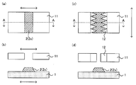
図11は、本開示の積層体の製造方法の一例を示す概略断面図である。図11においては、まず、基材1を準備する(図11(a))。次に、マスク11を用いた蒸着法により、複数の金属部2から構成される金属層200を形成する(図11(b))。言い換えると、複数の金属部2を含む第一金属層200aを形成する。この際、マスク11と、蒸着対象物である基材1との間に隙間Cを設けることにより、成膜時に金属が隙間C側に回り込み、頂面部(第一領域)21および裾引き部(第二領域)22を有する傾斜金属部2xが得られる(図11(c))。次に、必要に応じて、金属部2を覆うように誘電体層3を形成する(図11(d))。これにより、本開示の積層体が得られる。
図11は、本開示の積層体の製造方法の一例を示す概略断面図である。図11においては、まず、基材1を準備する(図11(a))。次に、マスク11を用いた蒸着法により、複数の金属部2から構成される金属層200を形成する(図11(b))。言い換えると、複数の金属部2を含む第一金属層200aを形成する。この際、マスク11と、蒸着対象物である基材1との間に隙間Cを設けることにより、成膜時に金属が隙間C側に回り込み、頂面部(第一領域)21および裾引き部(第二領域)22を有する傾斜金属部2xが得られる(図11(c))。次に、必要に応じて、金属部2を覆うように誘電体層3を形成する(図11(d))。これにより、本開示の積層体が得られる。
本開示によれば、マスクと蒸着対象物との間に隙間を設けることにより、傾斜金属部を有する積層体を得ることができる。また、本開示においては、所定のパターンが描かれたマスクを、蒸着源と蒸着対象物との間に設置させて、蒸着を行う。そのため、成膜およびパターニングを同時に行うことができ、さらに、上記隙間を設けることで、傾斜金属部を形成することもできる。
以下、本開示の積層体の製造方法について、工程ごとに説明する。
以下、本開示の積層体の製造方法について、工程ごとに説明する。
1.金属層形成工程
本開示における金属層形成工程は、マスクを用いた蒸着法により、金属層を形成する工程である。なお、マスクを用いた蒸着法により、第一金属層を形成する工程を、第一金属層形成工程と称する場合がある。本開示においては、マスクおよび蒸着対象物の間に隙間を設けることにより、複数の金属部の少なくとも一つとして、傾斜金属部を形成する。なお、例えば、基材上に金属膜を直接形成する場合には、基材が蒸着対象物になる。また、例えば、基材上に誘電体層を介して金属膜を形成する場合には、基材および誘電体層が蒸着対象物になる。
本開示における金属層形成工程は、マスクを用いた蒸着法により、金属層を形成する工程である。なお、マスクを用いた蒸着法により、第一金属層を形成する工程を、第一金属層形成工程と称する場合がある。本開示においては、マスクおよび蒸着対象物の間に隙間を設けることにより、複数の金属部の少なくとも一つとして、傾斜金属部を形成する。なお、例えば、基材上に金属膜を直接形成する場合には、基材が蒸着対象物になる。また、例えば、基材上に誘電体層を介して金属膜を形成する場合には、基材および誘電体層が蒸着対象物になる。
蒸着法としては、例えば、スパッタリング法、真空蒸着法、CVD法、電子線蒸着法等のドライプロセスを挙げることができる。また、傾斜金属部の形状、特に裾引き部(第二領域)の幅は、例えば、マスクおよび蒸着対象物の隙間を適宜選択することで制御することができる。マスクおよび蒸着対象物の隙間は、例えば50μm以上であり、200μm以上であっても良く、500μm以上であっても良い。一方、マスクおよび蒸着対象物の隙間は、例えば50mm以下である。また、裾引き部(第二領域)の幅は、成膜時の真空度にも影響を受ける。成膜時の真空度が高いほど、裾引き部(第二領域)の幅は小さくなる傾向にあり、成膜時の真空度が低いほど、裾引き部(第二領域)の幅は大きくなる傾向にある。
本開示においては、通常、マスクおよび蒸着対象物の隙間を設けることで傾斜金属部を形成するが、傾斜金属部が得られ易くなるように、傾斜金属部の形成促進処理を行っても良い。傾斜金属部の形成促進処理の一例としては、図12(a)、(b)に示すように、成膜時に、マスク11、および、蒸着対象物である基材1の少なくとも一方を揺動する処理が挙げられる。揺動する方向としては、例えば、ロールの幅方向が挙げられる。なお、図12(b)は、図12(a)のA-A断面図である。また、傾斜金属部の形成促進処理の他の例としては、図12(c)、(d)に示すように、マスク11に、金属の蒸着量を低下させる突起部12を設けて、成膜時に、マスク11を揺動する処理が挙げられる。揺動する方向としては、例えば、ロールの進行方向が挙げられる。なお、図12(d)は、図12(c)のA-A断面図である。
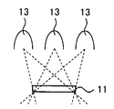
また、本開示においては、傾斜金属部が得られ易くなるように、マスクの形状を工夫しても良い。例えば、図13に示すように、蒸着源(図示せず)側の開口部のサイズO1が、蒸着対象物側の開口部のサイズO2よりも小さいマスク11を用いることで、傾斜金属部2xが得られ易くなる。また、本開示においては、傾斜金属部が得られ易くなるように、複数の蒸着源を用いても良い。例えば、図14に示すように、蒸着源13を複数設けて、複数の角度から蒸着を行うことで、傾斜金属部が得られ易くなる。
2.誘電体層形成工程
本開示の積層体の製造方法は、必要に応じて、誘電体層を形成する誘電体層形成工程を有していても良い。誘電体層の形成場所は特に限定されず、図4に示すように、基材1および金属層200(第一金属層200a)の間に誘電体層3を形成しても良く、金属部2を覆うように誘電体層3を形成しても良い。また、後者の一態様に該当するが、金属層が2層以上存在する場合には、各金属層の間に誘電体層を形成しても良い。例えば、第一金属層および第二金属層の間に誘電体層を形成しても良い。
本開示の積層体の製造方法は、必要に応じて、誘電体層を形成する誘電体層形成工程を有していても良い。誘電体層の形成場所は特に限定されず、図4に示すように、基材1および金属層200(第一金属層200a)の間に誘電体層3を形成しても良く、金属部2を覆うように誘電体層3を形成しても良い。また、後者の一態様に該当するが、金属層が2層以上存在する場合には、各金属層の間に誘電体層を形成しても良い。例えば、第一金属層および第二金属層の間に誘電体層を形成しても良い。
誘電体層の形成方法は特に限定されないが、例えば、スパッタリング法、真空蒸着法、CVD法、電子線蒸着法等のドライプロセスを挙げることができる。なお、金属層の形成と、誘電体層の形成とが、ともにドライプロセスであると、インラインで金属層および誘電体層の形成ができるという利点がある。すなわち、金属層形成工程(例えば第一金属層形成工程)および誘電体層形成工程が連続的に行われることが好ましい。金属層形成工程および誘電体層形成工程を連続的に行う方法としては、例えば、Roll to Roll法を挙げることができる。また、金属層を2層以上形成する場合には、例えば、金属層形成工程および誘電体層形成工程を複数繰り返せば良い。
3.積層体
本開示により得られる積層体については、上記「A.積層体」に記載した内容と同様であるので、ここでの記載は省略する。
本開示により得られる積層体については、上記「A.積層体」に記載した内容と同様であるので、ここでの記載は省略する。
なお、本開示は、上記実施形態に限定されるものではない。上記実施形態は例示であり、本開示の特許請求の範囲に記載された技術的思想と、実質的に同一の構成を有し、同様な作用効果を奏するものは、いかなる場合であっても本開示の技術的範囲に包含される。
以下、実施例を用いて、本開示をさらに具体的に説明する。
[実施例1]
(金属層の作製)
二軸配向透明PETフィルム(東洋紡績社製、A4100、厚み50μm、Tg67℃)をキャノンアネルパ製スパッタ装置SPC-350UHVに、PETの平滑面側に成膜されるよう設置した。ターゲットとしてAgを用いた。ターゲットと、蒸着対象物であるPETとの間に蒸着マスクを挿入し、マスクと蒸着対象物との距離を100μmとなるように調整した。蒸着マスクにはストライプ状のパターンが形成されており、L/S=200μm/200μmであった。その後、チャンバ内圧力が2.0×10-3Pa以下となるまで排気し、放電ガスとしてArを25sccm導入した。その後、チャンバ内圧力を0.4Paに調節し、直流スパッタリング法を用いて放電電流を0.2Aとした。この時、基材(PETフィルム)温度は室温とした。これにより、PET上にストライプ状の傾斜金属部を有する金属層(Ag層)を成膜した。
(金属層の作製)
二軸配向透明PETフィルム(東洋紡績社製、A4100、厚み50μm、Tg67℃)をキャノンアネルパ製スパッタ装置SPC-350UHVに、PETの平滑面側に成膜されるよう設置した。ターゲットとしてAgを用いた。ターゲットと、蒸着対象物であるPETとの間に蒸着マスクを挿入し、マスクと蒸着対象物との距離を100μmとなるように調整した。蒸着マスクにはストライプ状のパターンが形成されており、L/S=200μm/200μmであった。その後、チャンバ内圧力が2.0×10-3Pa以下となるまで排気し、放電ガスとしてArを25sccm導入した。その後、チャンバ内圧力を0.4Paに調節し、直流スパッタリング法を用いて放電電流を0.2Aとした。この時、基材(PETフィルム)温度は室温とした。これにより、PET上にストライプ状の傾斜金属部を有する金属層(Ag層)を成膜した。
(誘電体層の作製)
次に、ターゲットをTiに交換し、チャンバ内圧力が2.0×10⁻³Pa以下となるまで排気し、Arを10sccm、O2を5sccm導入し、全流量を15sccmとした。その後、チャンバ内圧力を0.4Paに調節し、直流スパッタリング法を用いて放電電流を0.3Aとした。この時、基材(PETフィルム)温度は室温とした。これにより、Ag層上にTiO2を成膜した。これにより、ストライプ状の傾斜金属部を有する積層体(フィルム)を得た。
次に、ターゲットをTiに交換し、チャンバ内圧力が2.0×10⁻³Pa以下となるまで排気し、Arを10sccm、O2を5sccm導入し、全流量を15sccmとした。その後、チャンバ内圧力を0.4Paに調節し、直流スパッタリング法を用いて放電電流を0.3Aとした。この時、基材(PETフィルム)温度は室温とした。これにより、Ag層上にTiO2を成膜した。これにより、ストライプ状の傾斜金属部を有する積層体(フィルム)を得た。
[比較例1]
蒸着マスクと、蒸着対象とを密着させて金属層を形成したこと以外は、実施例1と同様にして積層体を得た。得られた積層体は、傾斜金属部を有していなかった。
蒸着マスクと、蒸着対象とを密着させて金属層を形成したこと以外は、実施例1と同様にして積層体を得た。得られた積層体は、傾斜金属部を有していなかった。
[評価]
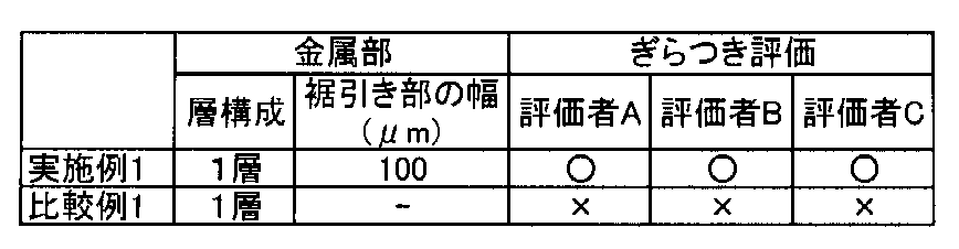
実施例1および比較例1で得られた積層体を用いて、ぎらつき性を評価した。具体的には、サンプルから30cm離れた状態で、観察者が各サンプルを観察し、ぎらつきの程度を評価した。評価は、ぎらつきの少ないサンプルを○とし、ぎらつきの激しいサンプルを×とし、その中間の程度のものを△とした。その結果を表1に示す。
実施例1および比較例1で得られた積層体を用いて、ぎらつき性を評価した。具体的には、サンプルから30cm離れた状態で、観察者が各サンプルを観察し、ぎらつきの程度を評価した。評価は、ぎらつきの少ないサンプルを○とし、ぎらつきの激しいサンプルを×とし、その中間の程度のものを△とした。その結果を表1に示す。
[実施例2]
実施例1で得られたサンプルのTiO2面側に、実施例1と同様の成膜条件にて、ストライプ状の傾斜金属部を有する金属層(Ag層)と、誘電体層(TiO2)層とを積層した。2層目のAg層を積層する際に、蒸着マスクを150μm分だけストライプの伸びる方向に対して直交する方向にずらし、1層目の傾斜金属部と、2層目の傾斜金属部とが、断面方向から観察した際に、ずれた位置となるように調整した。これにより、第一金属層および第二金属層を有する積層体を得た。第一金属層および第二金属層を構成する金属部は、ともにストライプ状の傾斜金属部であった。また、重複部における頂面部(第一領域)の幅(図7に示すW2)は、2箇所とも0μmであった。
実施例1で得られたサンプルのTiO2面側に、実施例1と同様の成膜条件にて、ストライプ状の傾斜金属部を有する金属層(Ag層)と、誘電体層(TiO2)層とを積層した。2層目のAg層を積層する際に、蒸着マスクを150μm分だけストライプの伸びる方向に対して直交する方向にずらし、1層目の傾斜金属部と、2層目の傾斜金属部とが、断面方向から観察した際に、ずれた位置となるように調整した。これにより、第一金属層および第二金属層を有する積層体を得た。第一金属層および第二金属層を構成する金属部は、ともにストライプ状の傾斜金属部であった。また、重複部における頂面部(第一領域)の幅(図7に示すW2)は、2箇所とも0μmであった。
[実施例3]
重複部における頂面部(第一領域)の幅(図7に示すW2)を、2箇所とも75μmとしたこと以外は、実施例2と同様にして積層体を得た。
重複部における頂面部(第一領域)の幅(図7に示すW2)を、2箇所とも75μmとしたこと以外は、実施例2と同様にして積層体を得た。
[実施例4]
重複部における頂面部(第一領域)の幅(図7に示すW2)を、2箇所とも120μmとしたこと以外は、実施例2と同様にして積層体を得た。
重複部における頂面部(第一領域)の幅(図7に示すW2)を、2箇所とも120μmとしたこと以外は、実施例2と同様にして積層体を得た。
[比較例2]
蒸着マスクと、蒸着対象とを密着させて、第一金属層および第二金属層を形成したこと以外は、実施例1と同様にして積層体を得た。得られた積層体は、傾斜金属部を有していなかった。
蒸着マスクと、蒸着対象とを密着させて、第一金属層および第二金属層を形成したこと以外は、実施例1と同様にして積層体を得た。得られた積層体は、傾斜金属部を有していなかった。
[評価]
実施例2~4および比較例2で得られた積層体を用いて、視認性、赤外線反射性および電波透過性を評価した。視認性の評価は、サンプルから30cm離れた状態で、観察者が各サンプルを観察することにより行った。評価は、パターンが見えないサンプルを○とし、僅かにパターンが見えるが許容範囲であるサンプルを△とし、パターンが明確に見えるサンプルを×とした。
実施例2~4および比較例2で得られた積層体を用いて、視認性、赤外線反射性および電波透過性を評価した。視認性の評価は、サンプルから30cm離れた状態で、観察者が各サンプルを観察することにより行った。評価は、パターンが見えないサンプルを○とし、僅かにパターンが見えるが許容範囲であるサンプルを△とし、パターンが明確に見えるサンプルを×とした。
赤外線反射率の評価は、波長1500nm以上2200nm以下における平均光線反射率を求めることにより行った。具体的には、紫外可視近赤外分光光度V-7200(日本文構成)を用いて測定した。電波透過性の評価は、周波数1GHzにおける電波透過性を求めることにより行った。具体的には、電磁波シールド効果評価器TSES-KEC(テクノサイエンスジャパン製)を用い、KEC法で測定した。その結果を表2に示す。

表2に示すように、比較例2では、赤外線反射性および電波透過性は良好であったものの、視認性が悪かった。比較例2で得られた積層体は傾斜金属部を有しないため、第一金属層の金属部と第二金属層の金属部とが重複する重複部において、色味が濃くなった。これに対して、実施例2~4では、視認性、赤外線反射性および電波透過性の全てが、許容可能な程度に良好であった。なお、実施例4では、W2が、人間の目の解像限界である100μmよりも大きかったため、僅かにパターンが確認されたが、十分に許容可能であった。
1…基材
2…金属部
2x…傾斜金属部
3…誘電体層
4…重複部
10…積層体
21…頂面部(第一領域)
22…裾引き部(第二領域)
200…金属層
2…金属部
2x…傾斜金属部
3…誘電体層
4…重複部
10…積層体
21…頂面部(第一領域)
22…裾引き部(第二領域)
200…金属層
Claims (7)
- 電波透過性および赤外線反射性を有し、基材、および、複数の金属部を含む第一金属層を有する積層体であって、
前記第一金属層の前記複数の金属部の少なくとも一つとして、第一領域と、前記第一領域から連続的に厚さが減少した第二領域と、を有する第一傾斜金属部を備える、積層体。 - 前記第二領域の幅が、0.1μm以上である、請求項1に記載の積層体。
- 前記第一金属層の前記基板とは反対の面側に、複数の金属部を含む第二金属層を有し、
前記第二金属層の前記複数の金属部の少なくとも一つとして、第一領域と、前記第一領域から連続的に厚さが減少した第二領域と、を有する第二傾斜金属部を備える、請求項1または請求項2に記載の積層体。 - 前記第一傾斜金属部における前記第二領域と、前記第二傾斜金属部における前記第二領域とが平面視上重複する重複部を有する、請求項3に記載の積層体。
- 前記重複部における前記第一領域の幅が、100μm以下である、請求項4に記載の積層体。
- 前記重複部における前記第一傾斜金属部および前記第二傾斜金属部の合計厚さの最小値が、5nm以上である、請求項4または請求項5に記載の積層体。
- 電波透過性および赤外線反射性を有し、基材、および、複数の金属部を含む第一金属層を有する積層体の製造方法であって、
マスクを用いた蒸着法により、前記第一金属層を形成する第一金属層形成工程を有し、
前記第一金属層形成工程において、前記マスクおよび蒸着対象物の間に隙間を設けることにより、前記第一金属層の前記複数の金属部の少なくとも一つとして、第一領域と、前記第一領域から連続的に厚さが減少した第二領域と、を有する第一傾斜金属部を形成することを特徴とする積層体の製造方法。
Priority Applications (1)
| Application Number | Priority Date | Filing Date | Title |
|---|---|---|---|
| JP2017510688A JP6128298B1 (ja) | 2015-09-15 | 2016-09-15 | 電波透過性赤外線反射積層体およびその製造方法 |
Applications Claiming Priority (2)
| Application Number | Priority Date | Filing Date | Title |
|---|---|---|---|
| JP2015-181700 | 2015-09-15 | ||
| JP2015181700 | 2015-09-15 |
Publications (1)
| Publication Number | Publication Date |
|---|---|
| WO2017047716A1 true WO2017047716A1 (ja) | 2017-03-23 |
Family
ID=58289364
Family Applications (1)
| Application Number | Title | Priority Date | Filing Date |
|---|---|---|---|
| PCT/JP2016/077329 Ceased WO2017047716A1 (ja) | 2015-09-15 | 2016-09-15 | 電波透過性赤外線反射積層体およびその製造方法 |
Country Status (2)
| Country | Link |
|---|---|
| JP (2) | JP6128298B1 (ja) |
| WO (1) | WO2017047716A1 (ja) |
Citations (5)
| Publication number | Priority date | Publication date | Assignee | Title |
|---|---|---|---|---|
| JP2011180562A (ja) * | 2010-03-04 | 2011-09-15 | Konica Minolta Holdings Inc | 熱線遮断用基材 |
| JP2012126578A (ja) * | 2009-04-13 | 2012-07-05 | Asahi Glass Co Ltd | 自動車ガラス用積層体、その製造方法、およびフロントガラス |
| JP2013139107A (ja) * | 2012-01-04 | 2013-07-18 | Kiyoshi Chiba | 積層体 |
| JP2013210485A (ja) * | 2012-03-30 | 2013-10-10 | Kuraray Co Ltd | 再帰反射性を有する波長選択フィルタ及び窓材 |
| WO2015007580A1 (en) * | 2013-07-18 | 2015-01-22 | Basf Se | Solar light management |
Family Cites Families (1)
| Publication number | Priority date | Publication date | Assignee | Title |
|---|---|---|---|---|
| JP6035768B2 (ja) * | 2012-02-16 | 2016-11-30 | セイコーエプソン株式会社 | 干渉フィルター、光学モジュール、および電子機器 |
-
2016
- 2016-09-15 JP JP2017510688A patent/JP6128298B1/ja active Active
- 2016-09-15 WO PCT/JP2016/077329 patent/WO2017047716A1/ja not_active Ceased
-
2017
- 2017-04-13 JP JP2017079758A patent/JP2017159659A/ja active Pending
Patent Citations (5)
| Publication number | Priority date | Publication date | Assignee | Title |
|---|---|---|---|---|
| JP2012126578A (ja) * | 2009-04-13 | 2012-07-05 | Asahi Glass Co Ltd | 自動車ガラス用積層体、その製造方法、およびフロントガラス |
| JP2011180562A (ja) * | 2010-03-04 | 2011-09-15 | Konica Minolta Holdings Inc | 熱線遮断用基材 |
| JP2013139107A (ja) * | 2012-01-04 | 2013-07-18 | Kiyoshi Chiba | 積層体 |
| JP2013210485A (ja) * | 2012-03-30 | 2013-10-10 | Kuraray Co Ltd | 再帰反射性を有する波長選択フィルタ及び窓材 |
| WO2015007580A1 (en) * | 2013-07-18 | 2015-01-22 | Basf Se | Solar light management |
Also Published As
| Publication number | Publication date |
|---|---|
| JP2017159659A (ja) | 2017-09-14 |
| JP6128298B1 (ja) | 2017-05-17 |
| JPWO2017047716A1 (ja) | 2017-09-14 |
Similar Documents
| Publication | Publication Date | Title |
|---|---|---|
| KR102686484B1 (ko) | 전기전도성코팅 및 반사방지코팅을 갖는 헤드-업 디스플레이를 위한 복합 판유리 | |
| JP5640906B2 (ja) | 合わせガラス | |
| US20150212335A1 (en) | Reflective type imaging element and optical system, and method of manufacturing relective type imaging element | |
| US7508586B2 (en) | Zinc-based film manipulation for an optical filter | |
| CN108369368B (zh) | 反射型透明屏幕 | |
| CN110088057A (zh) | 附有介电质多层膜的玻璃板及其制造方法 | |
| CN103293582A (zh) | 双激光波段及中远红外兼容隐身膜系结构 | |
| EP4410756A1 (en) | Vehicle window assembly and vehicle | |
| US10816707B2 (en) | Gold color tone multilayer coat and reflector including the same | |
| JP2023037945A (ja) | ガラス体 | |
| CN114728845A (zh) | 玻璃体 | |
| EP3302963A1 (en) | Solar control film | |
| JP2017181911A (ja) | 電波透過性赤外線反射積層体および閉鎖部材 | |
| JP6128298B1 (ja) | 電波透過性赤外線反射積層体およびその製造方法 | |
| CN107430226B (zh) | 滤光器及包括其的成像装置 | |
| KR20210003655A (ko) | 나노 광 흡수층을 구비한 광 제어 필름 및 이를 이용한 표시장치 | |
| US20200369003A1 (en) | Solar control composite film | |
| US20250355149A1 (en) | High-performance signal-friendly solar-control films | |
| WO2016192468A1 (zh) | 触摸显示面板及其制造方法和显示装置 | |
| KR101877376B1 (ko) | 하이퍼볼릭 메타물질 구조체 | |
| KR101689852B1 (ko) | 그리드 패턴 구조를 포함하는 다층 투명전극 | |
| US20210197530A1 (en) | Solar control composite film | |
| WO2022030395A1 (ja) | 周波数選択表面装荷部材および車両用窓部材 | |
| JP2017056588A (ja) | 電波透過性赤外線反射積層体、閉鎖部材、および電波透過性赤外線反射積層体の製造方法 | |
| US20250237794A1 (en) | High-performance signal-friendly solar-control films |
Legal Events
| Date | Code | Title | Description |
|---|---|---|---|
| ENP | Entry into the national phase |
Ref document number: 2017510688 Country of ref document: JP Kind code of ref document: A |
|
| 121 | Ep: the epo has been informed by wipo that ep was designated in this application |
Ref document number: 16846587 Country of ref document: EP Kind code of ref document: A1 |
|
| NENP | Non-entry into the national phase |
Ref country code: DE |
|
| 122 | Ep: pct application non-entry in european phase |
Ref document number: 16846587 Country of ref document: EP Kind code of ref document: A1 |