WO2017046865A1 - タッチ検出方法、タッチ検出装置、及びタッチセンサコントローラ - Google Patents
タッチ検出方法、タッチ検出装置、及びタッチセンサコントローラ Download PDFInfo
- Publication number
- WO2017046865A1 WO2017046865A1 PCT/JP2015/076095 JP2015076095W WO2017046865A1 WO 2017046865 A1 WO2017046865 A1 WO 2017046865A1 JP 2015076095 W JP2015076095 W JP 2015076095W WO 2017046865 A1 WO2017046865 A1 WO 2017046865A1
- Authority
- WO
- WIPO (PCT)
- Prior art keywords
- value
- touch detection
- touch
- capacitance
- threshold
- Prior art date
- Legal status (The legal status is an assumption and is not a legal conclusion. Google has not performed a legal analysis and makes no representation as to the accuracy of the status listed.)
- Ceased
Links
Images










Classifications
-
- G—PHYSICS
- G06—COMPUTING OR CALCULATING; COUNTING
- G06F—ELECTRIC DIGITAL DATA PROCESSING
- G06F3/00—Input arrangements for transferring data to be processed into a form capable of being handled by the computer; Output arrangements for transferring data from processing unit to output unit, e.g. interface arrangements
- G06F3/01—Input arrangements or combined input and output arrangements for interaction between user and computer
- G06F3/03—Arrangements for converting the position or the displacement of a member into a coded form
- G06F3/041—Digitisers, e.g. for touch screens or touch pads, characterised by the transducing means
- G06F3/0416—Control or interface arrangements specially adapted for digitisers
- G06F3/0418—Control or interface arrangements specially adapted for digitisers for error correction or compensation, e.g. based on parallax, calibration or alignment
- G06F3/04186—Touch location disambiguation
-
- G—PHYSICS
- G06—COMPUTING OR CALCULATING; COUNTING
- G06F—ELECTRIC DIGITAL DATA PROCESSING
- G06F3/00—Input arrangements for transferring data to be processed into a form capable of being handled by the computer; Output arrangements for transferring data from processing unit to output unit, e.g. interface arrangements
- G06F3/01—Input arrangements or combined input and output arrangements for interaction between user and computer
- G06F3/03—Arrangements for converting the position or the displacement of a member into a coded form
- G06F3/041—Digitisers, e.g. for touch screens or touch pads, characterised by the transducing means
- G06F3/044—Digitisers, e.g. for touch screens or touch pads, characterised by the transducing means by capacitive means
- G06F3/0446—Digitisers, e.g. for touch screens or touch pads, characterised by the transducing means by capacitive means using a grid-like structure of electrodes in at least two directions, e.g. using row and column electrodes
-
- G—PHYSICS
- G06—COMPUTING OR CALCULATING; COUNTING
- G06F—ELECTRIC DIGITAL DATA PROCESSING
- G06F2203/00—Indexing scheme relating to G06F3/00 - G06F3/048
- G06F2203/041—Indexing scheme relating to G06F3/041 - G06F3/045
- G06F2203/04111—Cross over in capacitive digitiser, i.e. details of structures for connecting electrodes of the sensing pattern where the connections cross each other, e.g. bridge structures comprising an insulating layer, or vias through substrate
Definitions
- the present invention relates to a touch detection method, a touch detection device, and a touch sensor controller, and more particularly to a touch detection method, a touch detection device, and a touch sensor controller that detect a change in capacitance between sensor electrodes due to the proximity of an object. .
- the capacitive touch sensor has a configuration in which a plurality of X electrodes each extending in the Y direction and a plurality of Y electrodes each extending in the X direction are arranged to intersect each other. A process of inputting a predetermined signal to the Y electrode and taking out this signal in order from each X electrode is configured to be repeated in order for all the Y electrodes.
- an indicator such as a finger approaches the touch surface of the touch sensor
- a capacitance is generated between the X electrode and the Y electrode in the vicinity thereof, and a part of the current that has flowed to the X electrode through this capacitance is generated. Since the current is sucked in the direction of the indicator, the amplitude of the signal extracted from the X electrode is reduced.
- the capacitive touch sensor detects an increase in capacitance from this change in amplitude, and derives the coordinates indicating the center of gravity of the area where the capacitance is equal to or greater than the threshold as the position coordinates of the indicator.
- a touch detection device represented by a tablet terminal is generally configured by disposing a capacitive touch sensor on the display surface of a liquid crystal display device.
- a space air gap
- the fixing between the touch sensor and the liquid crystal display device is realized by a spacer or the like disposed at the edge of the display surface.
- the touch detection device having such an air gap is hereinafter referred to as “air gap type”.
- the air gap type touch detection device is advantageous in that the generation of moire can be avoided, the step of providing an adhesive layer on the liquid crystal display device can be omitted, and the replacement of a failed touch sensor is easy.
- the above-described capacitance increases in that portion, so that the indicator is detected over a very wide area. . Since the center of gravity of the wide area detected in this way does not necessarily coincide with the position indicated by the pointer, the accuracy of position detection is lowered due to the occurrence of deflection.
- Patent Document 1 is configured to determine that “deflection” has occurred when the number of electrodes that output a capacitance exceeding the touch threshold is greater than or equal to a predetermined number, and cancel the calculation of the contact position in that case.
- the air gap type touch detection device it is disclosed that when the continuous touchdown count, which is the number of times the touch position between the touch panel and the object is continuously output, is larger than a predetermined threshold, the deflection determination process is canceled. Yes.
- the cause of “deflection” is a strong pressing of the touch surface by the indicator, if this is detected as “deflection”, the position of the indicator cannot be detected. Therefore, even in such a case, the position of the indicator can be detected.
- Patent Document 1 merely allows the position of the indicator to be detected even when there is “deflection”, and the method for deriving the position coordinates of the indicator itself is the same as the conventional method described above. Since this is the same, the accuracy of deriving the position coordinates when “deflection” occurs is not so high as in the conventional case.
- Patent Document 2 discloses a technique for dynamically changing the threshold value of the capacitance provided for detecting the indicator depending on the type of the indicator.
- the threshold value is calculated by multiplying the average value of the detected capacitance values obtained in each of the immediately preceding predetermined number of frames by a predetermined coefficient (for example, 1/2). According to this, a plurality of types of indicators having different capacitance detection values can be suitably detected.
- Patent Document 3 discloses a touch detection device that detects an indicator based on a difference value (DIFF value) between a capacitance detection value (RAW value) and a baseline value.
- This touch detection device sets a “large object flag” when the difference value exceeds a threshold value in an area having a certain area or more, and does not perform coordinate calculation processing when the “large object flag” is set. Therefore, a function to prevent detection of a large object such as a palm, and a process (calibration) for setting the RAW value to the baseline value when the “large object flag” is set for a predetermined time or longer. After that, it has a function of preventing the change in capacitance due to the proximity of a large object such as a palm from being reflected in the difference value.
- DIFF value difference value
- RAW value capacitance detection value
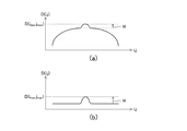
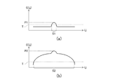
- FIG. 26 (a) is a schematic diagram showing a change of the capacitance C (i, j) depending on the coordinates (i, j) when “deflection” is not generated in the air gap type touch detection device.
- FIG. 26B is a schematic diagram showing a change in the capacitance C (i, j) depending on the coordinates (i, j) when “deflection” occurs.
- the small convex part which has appeared near the center represents the convex part by the indicator.
- the peak value P2 of the capacitance C when “deflection” occurs is the capacitance when “deflection” does not occur.
- the value is considerably larger than the peak value P1 of C. This is because, when “deflection” occurs, a convex portion is formed by the indicator on the wide convex portion generated by “deflection”.
- the threshold value T of the capacitance C is set to a value smaller than the peak value P1, as illustrated in FIG. Must be set.
- the accuracy of position detection decreases when “deflection” occurs as shown in FIG. . That is, as understood from FIG. 26B, the region S2 detected by the touch sensor in this case coincides with the position of the convex portion due to “deflection”, not the indicator. Therefore, even if the center of gravity of the region S2 is derived, only the center position of “deflection” is obtained, and the position of the indicator cannot be obtained. That is, the position of the indicator cannot be detected correctly.
- one of the objects of the present invention is a touch detection method, a touch detection device, and a touch detection method that can appropriately detect only the convex portion by the indicator, even when a convex portion wider than the convex portion by the indicator has occurred. And providing a touch sensor controller.
- the air gap type touch detection device has a problem that hysteresis occurs in “deflection”. That is, for example, the “deflection” caused by the touch by the indicator is not eliminated immediately after the indicator leaves the touch surface, but is gradually eliminated over a certain period of time (for example, several milliseconds). Since the position detection by the touch detection device is continued during that time, the center of gravity of the convex portion due to “deflection” is derived as the position of the indicator until the convex portion due to “deflection” becomes sufficiently small. Become.
- another object of the present invention is to provide a touch detection method, a touch detection device, and a touch sensor controller that can prevent erroneous detection of the position of an indicator caused by hysteresis of “deflection”.
- the inventor of the present application often forms the touch detection device in a size that can be held with one hand, it is an air gap type in a state where it is held with one hand as shown in FIG.
- the touch detection device is used, pressure is applied to the back surface of the touch detection device through the user's hand, and it has been newly found that a wide convex portion similar to the case of touching the touch surface with a palm may be detected.
- this way of holding the touch detection device is referred to as “back support”.
- Such a back support occurs in a touch detection device used in an operation unit (see FIGS. 19 and 21) of a multi-function peripheral device that performs scanning and copying, such as the touch detection device of Patent Document 3.
- the back support is frequently performed in tablet terminals and the like that have been remarkably reduced in thickness and weight.
- the wide convex portion generated by the back surface support and the wide convex portion generated when the palm touches the touch surface are canceled from the difference value without distinction.
- touch detection that is an operation unit of a multi-function peripheral device that is often limited in operations such as menu selection as described in Patent Document 3. Unlike the apparatus, it is not preferable to perform the calibration as described above.
- performing calibration means setting the detected value of the currently detected capacitance as a reference state. If calibration is performed during the touch, the reference state follows the detected value. Therefore, it is inherently a contradictory relationship to perform touch detection while performing calibration. For example, if you try to use a position indicator on a tablet terminal that is different from a finger, such as a so-called touch pen or passive pen, as you would with a writing instrument on paper placed on a desk, The side of the palm that holds the container is first placed on the touch surface. Here, if the calibration is executed with the state of the capacitance generated by the palm side being maintained, the position indicator is used from the state where the user places the palm side to the tablet terminal. Even if input is started, there is a possibility that it cannot be detected at that moment by an indicator (or index finger). This is the reason why it is not preferable to perform calibration in a general-purpose touch detection device.
- another object of the present invention is to provide a touch detection method, a touch detection device, and a touch sensor controller capable of executing calibration only for a wide convex portion generated by a back support. is there.
- a touch detection method is a touch detection method executed by a controller of a capacitive touch sensor including a plurality of sensor electrodes, wherein an indicator is provided for each crossing position of the plurality of sensor electrodes. And a step of obtaining a detection value corresponding to a capacitance between the touch sensors, a step of obtaining a maximum value among the detection values for each intersection position, and a fixed value or the maximum value Determining the first threshold value to a value obtained by subtracting the subtraction value, which is a value that decreases as the value increases from the maximum value, and the indication based on the detection value for each of the intersection positions with respect to the first threshold value. Deriving the position of the body.
- the step of deriving the position of the indicator is configured to derive the position of the indicator based on the detected value for each of the intersection positions with reference to the reset first threshold. It is good as well.
- a touch detection method is a touch detection method executed by a controller of a capacitive touch sensor including a plurality of sensor electrodes, and a reference for each intersection position of the plurality of sensor electrodes.
- a step of acquiring a value a step of acquiring a capacitance value indicating the capacitance for each intersection position, and a pointer and the touch sensor for each intersection position based on the capacitance value and the reference value Obtaining a detection value corresponding to the capacitance between the two, calculating a representative position of the region indicated by the intersection position where the corresponding detection value exceeds the first threshold, and whether or not the representative position has moved
- a calibration for calibrating the reference value in a direction approaching the detection value is activated in accordance with a determination result of the determination step and the determination step of whether or not there is movement.
- a touch detecting method comprising the steps.
- a touch detection device provides a plurality of sensor electrodes constituting a capacitive touch sensor and a capacitance between the indicator and the touch sensor at each intersection position of the plurality of sensor electrodes.
- a touch detection unit that acquires a capacitance value to be shown, and a maximum value among detection values that are values based on the capacitance value for each of the intersection positions, and is a fixed value or smaller as the maximum value is larger
- the first threshold value is determined to a value obtained by subtracting the subtraction value, which is a value obtained from the maximum value, and the position of the indicator is determined based on the detected value for each intersection position with the determined first threshold value as a reference.
- a touch detection device including a coordinate deriving unit for deriving.
- a touch detection device acquires a plurality of sensor electrodes constituting a capacitive touch sensor and a reference value for each intersection position of the plurality of sensor electrodes, and for each intersection position.
- a touch detection unit that obtains a capacitance value indicating the capacitance, and calculates a difference value obtained by subtracting the corresponding reference value from the corresponding capacitance value for each intersection position; and the difference value or Calculate the representative position of the region indicated by the intersection position where the detection value acquired based on the difference value exceeds the first threshold and determine whether or not the representative position has moved, and according to the determination result, And a coordinate deriving unit that activates calibration for calibrating the reference value in a direction approaching the detection value.
- a touch sensor controller is a touch sensor controller that is used together with a plurality of sensor electrodes that constitute a capacitive touch sensor.
- a touch detection unit that acquires a capacitance value indicating capacitance between touch sensors, and a maximum value among detection values that are values based on the capacitance value for each of the intersection positions, and is a fixed value, or
- the first threshold value is determined to a value obtained by subtracting the subtraction value, which is a value that decreases as the maximum value increases, from the maximum value, and the detected value for each intersection position is determined based on the determined first threshold value.
- a touch sensor controller including a coordinate deriving unit for deriving the position of the indicator based on the touch sensor controller.
- a touch sensor controller is a touch sensor controller that is used together with a plurality of sensor electrodes constituting a capacitive touch sensor, and calculates a reference value for each intersection position of the plurality of sensor electrodes.
- a touch for obtaining a capacitance value indicating the capacitance for each intersection position and calculating a difference value obtained by subtracting the corresponding reference value from the corresponding capacitance value for each intersection position.
- a touch sensor controller including a coordinate deriving unit that activates calibration for calibrating the reference value in a direction approaching the detection value according to the determination result. It is a controller.
- the first threshold value serving as a reference for position derivation is determined by the value obtained by subtracting the subtracted value from the maximum value. Even when a convex portion (hereinafter referred to as a “wide convex portion”) wider than a portion (hereinafter referred to as “indicator convex portion”) is generated, only the indicator convex portion is appropriately detected. Is possible.
- the subtraction value may be a fixed value, but it is more preferable that the subtraction value is a value that decreases as the detected maximum value increases. This means that the higher the wide convex portion, the larger the maximum value that can be detected, while the higher the wide convex portion, the height of the indicator convex portion positioned above it (height from the top of the wide convex portion). This is because tends to be small.
- the first threshold is reset to a larger value in the scene where the first threshold is lowered, the lowering of the first threshold is delayed. Can do. Therefore, since the position of the indicator based on the first threshold value is not derived in such a scene, it is possible to prevent erroneous detection of the position of the indicator caused by the “deflection” hysteresis.
- the calibration is started only when the representative position is not moved. Therefore, only the wide convex portion generated by the back support is set as a calibration target. Is possible. It should be noted that this one side surface has a wide convex portion caused by supporting the back surface, and the wide convex portion generated by performing the back surface support may greatly wobble the touch detection device itself when the back surface is supported. Although there is no change in the relative positional relationship between the fulcrum (plural fingers) indicating the back surface and the touch detection device, time has elapsed compared to the wide convex portion generated by the palm touching the touch surface. Therefore, it is an invention based on a new finding that these wide convex portions can be distinguished by detecting the presence or absence of the movement.
- the calibration is performed when it is determined that the wide convex portion is generated by the back support, and thus the back support is maintained for a while such as when a moving image is viewed.
- the back support is maintained for a while such as when a moving image is viewed.
- FIG. 6 is a schematic diagram illustrating a state where the vicinity of the center of the touch surface 5a is pressed (state S3), and FIG.
- 9E is a schematic diagram illustrating a state where the touch detection device 1 is supported on the back by the palm 8b (state S4).
- (F) is a schematic diagram showing a state (states S5 and S6) in which the vicinity of the center of the touch surface 5a is pressed by the finger 8 while the touch detection device 1 is supported on the back by the palm 8b.
- (A) shows the locus of the center of gravity of the convex portion detected in the state S4 shown in FIG. The trajectory of the movement of the center of gravity of the convex portion detected in the state S3 shown in FIG. It is a figure which shows the processing flow of the touch detection process which the touch detection part 15 shown in FIG. 2 performs. It is a figure which shows the processing flow of the coordinate derivation process which the coordinate derivation part 16 shown in FIG. 2 performs. It is a figure for demonstrating the suitable determination method of the subtraction value R shown in FIG.13 and FIG.14. It is a figure for demonstrating the meaning of step ST12 shown in FIG. It is a figure which shows the effect of the calibration which the touch detection part 15 shown in FIG. 2 performs.
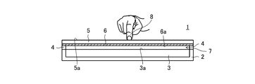
- FIG. 1 is a cross-sectional view of a touch detection device 1 according to the present embodiment
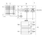
- FIG. 2 is a schematic block diagram showing functional blocks of the touch detection device 1.
- the touch detection device 1 includes a housing 2 formed in a box shape without an upper lid of a substantially rectangular parallelepiped, and a display housed inside the housing 2 with the display surface 3a facing upward.
- the device 3 the transparent cover panel 5 disposed above the display surface 3a, the touch sensor 6 attached to the lower surface of the cover panel 5 (the surface facing the display surface 3a), the cover panel 5 and the touch sensor 6 and a spacer 4 that supports 6.
- the spacer 4 is disposed over the entire circumference of the edge of the housing 2.
- the touch detection device 1 includes a touch sensor controller 10, a storage unit 20, and a host CPU.
- the touch detection method according to the present embodiment is executed by the touch sensor controller 10.
- the touch detection device 1 the upper surface of the cover panel 5 constitutes the touch surface 5a.
- the input operation to the touch detection device 1 is executed by moving an indicator such as the finger 8 illustrated on the touch surface 5a.
- an electronic pen or the like corresponding to the electrostatic capacity method can be used as the indicator for the touch sensor 6, but in the following, for simplicity of explanation, the finger 8 is used as the indicator. It will be explained as a thing.
- the touch sensor 6 and the display surface 3a are not in close contact with each other, and a certain space (air gap 7) is provided between them. That is, the touch detection device 1 is the above-described air gap type touch detection device.
- the display device 3 is a device for displaying characters and images based on the control of the host CPU shown in FIG. Specifically, a liquid crystal display or an organic EL display is preferably used as the display device 3, but the display device 3 can be configured by a display other than these.
- the touch sensor 6 is a capacitive touch sensor, and extends in the Y direction (one direction in the touch surface 5a shown in FIG. 1) and X direction (shown in FIG. 1) as shown in FIG.
- a plurality of X electrodes 6x arranged at equal intervals in the touch surface 5a) and a plurality of Y electrodes 6y extending in the X direction and arranged at equal intervals in the Y direction. Are configured so as to intersect each other.
- the X electrode 6x and the Y electrode 6y constitute a sensor electrode of the touch sensor 6.
- Each of the X electrodes 6x and the Y electrodes 6y is made of a transparent conductive material such as an ITO transparent conductive film.
- the user of the touch detection device 1 moves the display surface 3a of the display device 3 through the touch surface 5a. Can see.
- a capacitance is generated between the finger 8 and the X electrode 6x and the Y electrode 6y in the vicinity thereof.
- the touch sensor controller 10 illustrated in FIG. 2 is configured to detect the position of the finger 8 on the touch surface 5a using the change in capacitance. This point will be described in more detail later.
- the cover panel 5 is made of a transparent material having high strength against the pressing force against the touch surface 5a, such as glass or plastic. However, when the user strongly presses the touch surface 5 a, the cover panel 5 bends in the direction of the display surface 3 a together with the touch sensor 6. Since this deflection affects the capacitance described above, it also affects the detection of the finger 8 by the touch sensor controller 10. This point will also be described in more detail later.
- the touch sensor controller 10 includes an oscillator 11, multiplexers 12 and 13, an analog / digital converter (A / D) 14, a touch detection unit 15, and a coordinate deriving unit 16. Composed.
- the oscillator 11 is a circuit that oscillates a signal having a predetermined frequency.
- the multiplexer 12 is a circuit that plays a role of sequentially selecting a plurality of X electrodes 6x one by one at a predetermined time interval and connecting the oscillator 11 to the selected X electrodes 6x. Due to the function of the multiplexer 12, the signal output from the oscillator 11 is sequentially supplied to each of the plurality of X electrodes 6x. The signal supplied to the X electrode 6x is supplied to each Y electrode 6y through the intersection position (i, j) with each Y electrode 6y.
- i and j are natural numbers indicating the serial numbers of the X electrode 6x and the Y electrode 6y, respectively, and the coordinates of each intersection position on the touch surface 5a are indicated by a combination (i, j) of i and j.
- the maximum values of i and j are M and N as shown in FIG.
- the multiplexer 13 is a circuit that sequentially selects a plurality of Y electrodes 6y one by one at predetermined time intervals and connects the selected Y electrodes 6y to the input terminal of the analog-to-digital converter 14.
- the analog-to-digital converter 14 has a function of generating a digital signal by sampling and quantizing the signal supplied from each Y electrode 6 y and supplying the generated digital signal to the touch detection unit 15.
- the touch detection unit 15 performs a capacitance value C (i, i) indicating the capacitance between the finger 8 and the touch sensor 6 for each intersection position (i, j). j) is configured to obtain.
- a specific circuit configuration of the touch detection unit 15 for example, a hardware circuit such as a programmable logic controller is used.
- the touch detection unit 15 also has a function of converting the capacitance value C (i, j) into a difference value D (i, j) (a detection value corresponding to the capacitance between the finger 8 and the touch sensor 6). More specifically, as shown in FIG. 2, the storage unit 20 includes a frame memory FM0 that stores a reference value S (i, j) for each intersection position (i, j), and an intersection position (i, j). ) And a frame memory FM1 for storing a difference value D (i, j). The touch detection unit 15 reads the reference value S (i, j) from the frame memory FM0 for each intersection position (i, j), and the read reference value S (i, j) by the following equation (1).
- a process of subtracting from the corresponding capacitance value C (i, j) is performed.
- the numerical value obtained as a result of the subtraction is stored in the frame memory FM1 as a difference value D (i, j) corresponding to each intersection position (i, j).
- the touch detection unit 15 determines whether there is a difference value D (i, j) that exceeds a pre-stored touch detection threshold value T2 (second threshold value, see FIG. 13 described later).
- T2 second threshold value
- the coordinate deriving unit 16 obtains the maximum value among the plurality of difference values D (i, j) stored in the frame memory FM1, and subtracts the subtraction value R from the maximum value to thereby detect the touch detection threshold value T1 (first value). And a function of deriving the position of the finger 8 based on the difference value D (i, j) for each intersection position (i, j) with the calculated touch detection threshold T1 as a reference. . In addition, the coordinate deriving unit 16 further calculates the center of gravity GCur (representative position) of the region indicated by one or more intersection positions (i, j) where the difference value D (i, j) exceeds the touch detection threshold T1.
- the coordinate deriving unit 16 is configured by an integrated circuit such as an MPU, for example, and is configured to implement each function including the above three functions by executing a program supplied from the outside.
- the difference value D (i, j) stored in the frame memory FM1 will be described with a specific example for each state of the positional relationship between the user's hand (including the finger 8) and the touch detection device 1. To do.
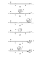
- FIG. 3A shows a state where the user's hand does not exist in the vicinity of the touch detection device 1 (state S0).
- FIG. 3B shows a state where the finger 8 is pressing near the center of the touch surface 5a (state S1).
- FIG. 3C shows a state where the vicinity of the end of the touch surface 5a is pressed by the finger 8 (state S2).
- FIG. 3D shows a state where the center of the touch surface 5a is pressed by the fist 8a (state S3).
- FIG. 3A shows a state where the user's hand does not exist in the vicinity of the touch detection device 1 (state S0).
- FIG. 3B shows a state where the finger 8 is pressing near the center of the touch surface 5a (state S1).
- FIG. 3C shows a state where the vicinity of the end of the touch surface 5a is pressed by the finger 8 (state S2).
- FIG. 3D shows a state where the center of the touch surface 5a is pressed by the fist 8a (state S
- FIG. 3E shows a state where the touch detection device 1 is supported on the back by the palm 8b (state S4).
- FIG. 3F shows a state (states S5 and S6) in which the vicinity of the center of the touch surface 5a is pressed by the finger 8 while the back surface of the touch detection device 1 is supported by the palm 8b.
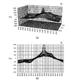
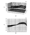
- FIG. 4 is a diagram illustrating an example of the difference value D (i, j) in the state S0 illustrated in FIG. 4 shows an example in which 36 X electrodes 6x, TX00 to TX35, and 63 Y electrodes 6y, RX00 to RX62, are provided.
- the depth axis is the X coordinate
- the horizontal axis represents the Y coordinate
- the vertical axis represents the difference value D (i, j).
- FIG. 4B the horizontal axis represents the Y coordinate
- the vertical axis represents the difference value D (i, j).
- FIG. 4B is a view of FIG. 4A viewed in the depth direction.
- the difference value D (i, j) in the state S0 is almost zero at any position on the touch surface 5a. This is an indicator including the user's hand in the vicinity of the touch detection device 1. Indicates that nothing exists. However, even in this case, the capacitance value C (i, j) is usually different for each coordinate, and in order to obtain a uniform difference value D (i, j) as shown in FIG.
- the reference value S (i, j) needs to be adjusted in advance.
- FIG. 5 shows an example of the reference value S (i, j) adjusted in this way.
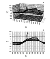
- FIG. 6 is a diagram illustrating an example of the difference value D (i, j) in the state S1 illustrated in FIG.
- the convex part generated near the center of the touch surface 5a is an indicator convex part reflecting the capacitance generated between the finger 8 located near the center of the touch surface 5a and the touch sensor 6. is there.
- the difference value D (i, j) is also large around the indicator convex portion, but this is a wide convex portion generated by the deflection of the touch sensor 6. That is, as illustrated in FIG. 3B, depending on the pressing force of the finger 8, the touch sensor 6 may bend due to the pressing of the touch surface 5a.
- the capacitance value C (i, j) detected by the touch detection unit 15 increases, so that a wide convex portion near the pressing point as shown in FIG. Will occur.
- One of the features of the touch detection device 1 according to the present embodiment is that it is possible to appropriately detect only the indicator convex portion even when the wide convex portion is generated as described above. Therefore, in the present embodiment, a touch detection threshold T1 obtained by subtracting the subtraction value R from the maximum value of the difference value D (i, j) is used. Details will be described later with reference to FIGS. 13 and 14.
- FIG. 7 is a diagram illustrating an example of the difference value D (i, j) in the state S2 illustrated in FIG.
- the convex portion generated near the end of the touch surface 5a is the indicator convex reflecting the capacitance generated between the finger 8 located near the end of the touch surface 5a and the touch sensor 6.
- the indicator convex portion is smaller than the indicator convex portion of FIG. 6 because the sensitivity of the touch sensor 6 is weak in the vicinity of the end portion of the touch surface 5a.
- the difference value D (i, j) is large around the indicator convex portion, which is a wide convex portion generated by the deflection of the touch sensor 6 as in the case of FIG. Since the pressing point is the end portion of the touch surface 5a, the indicator convex portion by the finger 8 is located near the end portion of the wide convex portion by the deflection.
- FIG. 8 is a diagram illustrating an example of the difference value D (i, j) in the state S3 illustrated in FIG.
- the indicator convex part is not generated, but the relatively narrow wide convex part is formed on the relatively wide wide convex part.
- the latter wide convex portion reflects the capacitance generated between the fist 8 a and the touch sensor 6, and the former wide convex portion is caused by the deflection of the touch sensor 6.
- FIG. 9 is a diagram illustrating an example of the difference value D (i, j) in the state S4 illustrated in FIG. Also in the figure, the indicator convex portion is not generated, and one wide convex portion is generated. This wide convex part is caused by the back support, and its center of gravity does not move compared to the wide convex part by the fist 8a shown in FIG. 8 or the wide convex part by the deflection caused by pressing the touch surface 5a. It has characteristics.
- FIG. 12 shows a locus of movement of the center of gravity of the convex portion over a predetermined time.
- FIG. 12A shows the movement of the center of gravity of the wide convex portion detected in the state S4 shown in FIG.
- FIG. 12B shows a locus of the movement of the center of gravity of the wide convex portion detected in the state S3 shown in FIG.
- the center of gravity of the wide convex portion generated by the back support hardly moves compared to the center of gravity of the wide convex portion generated by the fist 8a.
- the wide convex portion generated by the back support has a feature that the center of gravity hardly moves.
- touch detection unit 15 performs only the wide convex portion generated by the back support by using the feature of the wide convex portion generated by the back support. This is because it can be the target of calibration processing. Details thereof will be described later with reference to FIGS. 13 and 14.
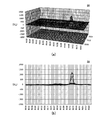
- 10 and 11 are diagrams showing examples of the difference value D (i, j) in the states S5 and S6 shown in FIG. 3 (f).
- the state S5 is a state before the touch detection unit 15 executes the calibration process
- the state S6 is a state after the touch detection unit 15 executes the calibration process.
- the convex portion generated near the center of the touch surface 5 a is an indicator that reflects the capacitance generated between the finger 8 positioned near the center of the touch surface 5 a and the touch sensor 6. It is a convex part. 10 and 11 are different in the position of the indicator protrusion, but this is due to the convenience of measurement and is not an essential difference.
- FIG. 10 a wide convex portion supported by the back surface appears similar to that shown in FIG. 9 around the indicator convex portion.
- the calibration process performed by the touch detection unit 15 is for canceling the wide convex part. After the calibration process is performed, as shown in FIG. Only the part appears. Detailed contents of the calibration process will be described later with reference to FIGS.
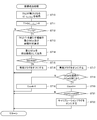
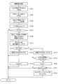
- FIG. 13 is a diagram illustrating a processing flow of touch detection processing performed by the touch detection unit 15.
- various values are set in the touch detection unit 15 (step ST0).
- the values set here include an initial reference value S 0 (i, j), a touch detection threshold T2, a subtraction value R, a palm determination value SQ0, a calibration coefficient A, and a calibration timer Count0.
- two frame memories FM0 frame memories storing the reference values S (i, j) shown in FIG. 2 are actually prepared, and the touch detection unit 15 repeats the main loop described later. These two are alternately selected, and in step ST3 described later, a reference value S (i, j) is read from one selected frame memory FM0, and in step ST3 described later, a reference value S ( i, j) is configured to write.
- the reference value S A (i, j) and the reference value S B (i, j) may be written, but the reference value S A (i, j) is obtained from the selected one of the frame memories FM0.
- the read reference value S (i, j) is indicated, and the reference value S B (i, j) is the reference value S (i, j) written in the other frame memory FM0.
- the initial reference value S 0 (i, j) is an initial value of the reference value S (i, j), and is set in the frame memory FM0 selected first.
- the reference value S (i, j) shown in FIG. 5 is an example of the initial reference value S 0 (i, j).
- step ST1 the touch detection unit 15 starts the main loop process (step ST1). This main loop is repeated until interrupted by an external interrupt such as a power interruption.
- the touch detection unit 15 first detects the capacitance value C (i, j) by referring to the digital signal supplied from the analog-digital converter 14 shown in FIG. 2 (step ST2). Next, the touch detection unit 15 reads the reference value S A (i, j) from the frame memory FM0 shown in FIG. The difference value D (i, j) is calculated in step ST3.
- the touch detection unit 15 determines whether any of the calculated difference values D (i, j) exceed the touch detection threshold T2 (step ST4).
- This is a process originally intended to determine whether or not the calculated difference value D (i, j) has an indicator convex portion, but the touch detection threshold value T2 is normally set lower.
- the touch detection threshold value T2 is normally set lower. In the process of step ST4, not only the indicator convex portion but also the wide convex portions as shown in FIGS. 6 to 10 are detected.
- step ST5 If a negative determination result is obtained in the process of step ST4, the touch detection unit 15 turns off the calibration flag (step ST5), and then proceeds to the next loop.
- the calibration flag will be described later.
- step ST6 when a positive determination result is obtained in the process of step ST4, the touch detection unit 15 causes the coordinate deriving unit 16 to perform a coordinate deriving process (step ST6).
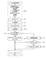
- FIG. 14 is a diagram illustrating a processing flow of the coordinate derivation process performed by the coordinate derivation unit 16.
- the coordinate deriving unit 16 first obtains a set of i, j (i max , j max ) that maximizes the difference value D (i, j) (step ST10).
- the touch detection threshold value T1 is calculated by subtracting the subtraction value R from the maximum value D (i max , j max ) of the difference value D (i, j) according to the following equation (2) (step ST11).
- the touch detection threshold value T1 is used to reliably detect only the indicator convex portion. Therefore, the subtraction value R needs to be equal to or less than the value corresponding to the height of the indicator convex portion (the height from the top when there is a wide convex portion). Specifically, it may be a fixed value, but it is more preferable that the value be smaller as the maximum value D (i max , j max ) is larger.
- FIG. 15 is a diagram for explaining a preferred method of determining the subtraction value R.
- FIG. 15A shows a case where there is a wide convex portion
- FIG. 15B shows a case where there is no wide convex portion.
- the maximum value D (i max , j max ) is generally larger when there is a wide convex portion than when there is no wide convex portion.
- the height H of the indicator convex portion is generally larger when the wide convex portion is not present than when the wide convex portion is present. That is, the maximum value D (i max , j max ) and the height H of the indicator convex portion have a negative correlation. From this, it can be said that the subtraction value R is preferably a value that becomes smaller as the maximum value D (i max , j max ) becomes larger.
- the coordinate deriving unit 16 that has calculated the touch detection threshold T1 compares the touch detection threshold T1 with the touch detection threshold T2 (step ST12). If the touch detection threshold value T1 is less than the touch detection threshold value T2, the process ends. Otherwise, the process proceeds to step ST13.
- FIG. 16 is a diagram for explaining the meaning of step ST12.
- FIG. 16A when the finger 8 is firmly touching the touch surface 5a but is not generated by bending, FIG. 16B shows that the finger 8 strongly presses the touch surface 5a and bending occurs.
- 16 (c) shows the case where the touch with the finger 8 is too weak, or the touch surface 5a is not touched, but something like a convex part is visible for some reason. Show.
- the touch detection threshold value T1 is larger than the touch detection threshold value T2.
- Step ST12 in FIG. 14 is a process for preventing the position coordinates of the indicator from being detected (not notified to the host CPU) in such a case.
- the coordinate deriving unit 16 extracts a region where the difference value D (i, j) exceeds the touch detection threshold T1, and performs a process of calculating the center of gravity GCur and the area SQ for each extracted region.
- the center of gravity GCur of the region is calculated by the following equation (3), and the number of intersection positions (i, j) included in the region is defined as the area SQ.
- AR in Equation (3) indicates that addition is performed for all intersection positions (i, j) in the extracted region.
- the center of gravity GCur is used as a representative position
- other feature amounts can be used as the representative position.
- the center of the region may be used as the representative position, or the point where the difference value D (i, j) is maximum in the region may be used as the representative position.
- the area SQ an example in which the number of intersection positions (i, j) included in the region is used as the area SQ will be described here, but the area of the figure indicated by the outer periphery of the region is calculated geometrically. It is also possible to use the area SQ.
- the coordinate deriving unit 16 outputs the center of gravity GCur calculated in step ST13 to the host CPU (see FIG. 2) as the position of the detected indicator (step ST14).
- the convex portion is detected by using the touch detection threshold T1 configured to detect only the indicator convex portion as a threshold, and the detected convexity. This is output to the host CPU as the representative position of the part. Therefore, according to the touch detection device 1 according to the present embodiment, when the indicator convex portion exists, only the indicator convex portion is appropriately detected, and the indicator is based on the detected indicator convex portion. It is realized that the position detection is performed. Further, when the representative position is calculated by Expression (3), it is only necessary to perform addition processing only in the region corresponding to the indicator convex portion, so that the calculation amount for coordinate derivation is reduced.
- the coordinate deriving unit 16 determines whether or not the calculated area SQ is equal to or greater than the palm determination value SQ0 (third threshold value) (step S15).
- this processing is processing for determining whether the detected area is a wide convex portion or a pointer convex portion.
- the area SQ is calculated using the touch detection threshold value T1
- the positive determination is made in step ST15 because the indicator convex portion exists in the difference value D (i, j) that is the detection target. This is the case.
- the coordinate deriving unit 16 When it is determined that the area SQ is not equal to or greater than the palm determination value SQ0, that is, when it is determined that the detected region is a pointer convex portion, the coordinate deriving unit 16 turns off the invalid flag (step ST16) and ends the process. To do.
- the invalid flag is a flag that is referred to by the host CPU.
- the host CPU treats the coordinates output by the coordinate deriving unit 16 at step ST14 as valid only when the invalid flag is off, and the invalid flag is on. If it is, the coordinate deriving unit 16 is configured to discard the coordinates output in step ST14.
- the coordinate deriving unit 16 first turns on the invalid flag (step ST17). . Thereby, the coordinates output by the coordinate deriving unit 16 in step ST14 are discarded by the host CPU.
- step ST17 the coordinate deriving unit 16 determines whether or not the center of gravity GCur is the same as the center of gravity GCur calculated in the immediately preceding loop (step ST18). In other words, this is processing for confirming whether or not the center of gravity GCur has moved. If it is determined in step ST18 that they are not the same, the coordinate deriving unit 16 sets 0 to the variable count (step ST19). In the first loop, since the result of step ST18 is always negative, 0 is set to the variable count. On the other hand, if it is determined in step ST18 that they are the same, the coordinate deriving unit 16 increments the variable count by 1 (step ST20). Then, it is determined whether or not the variable count is equal to or greater than the calibration timer Count0 (step ST21). If not, the process ends. If it is, the calibration flag is turned on (step ST22), and then the process is performed. finish.
- step ST7 determines whether or not the calibration flag is off.
- the process proceeds to the next loop.
- the reference value S (i, j) stored in the frame memory FM0 shown in FIG. 2 is updated by the following equation (4) (step ST8). ), Go to the next loop.
- Equation (4) means that the reference value S (i, j) is increased by the difference value D (i, j) multiplied by the calibration coefficient A.
- the calibration coefficient A is a constant that satisfies 0 ⁇ A ⁇ 1.
- step ST15 process for confirming whether the area SQ of the detected region is equal to or greater than the palm determination value SQ0
- the process of step ST18 process for confirming whether the center of gravity GCur has not moved
- this calibration processing is executed only when a wide convex portion supported by the back surface appears. Therefore, according to the touch detection device 1 according to the present embodiment, it is realized that only the wide convex portion generated by the back support is set as a calibration target.
- FIG. 17 is a diagram illustrating the effect of calibration performed by the touch detection unit 15.
- the time change of j) is shown schematically. Since the state S4 continues, if the calibration is not performed, the difference value D (i, j) will remain high, but as a result of the calibration being executed, the difference is reached by time t1.
- the value D (i, j) has decreased to the level of the touch detection threshold T2. More specifically, before the calibration is performed, the touch detection threshold T1 has a larger value than the touch detection threshold T2.
- step ST12 of FIG. 14 the result of determination in step ST12 of FIG. 14 is affirmative, and calibration is executed.
- the touch detection threshold T1 gradually decreases, and at time t1 shown in FIG. 17, the touch detection threshold T1 becomes smaller than the touch detection threshold T2.
- the result of determination in step ST12 of FIG. 14 is negative, calibration is not performed.
- the calculation of the center of gravity GCur and the area SQ in step ST13 is not performed, so that the calculation processing of the touch detection device 1 is reduced thereafter.
- FIG. 17 shows the difference value D (i, j) when the state S6 shown in FIG. 3E (the state where the back surface is supported and the touch surface 5a is touched with the finger 8) is reached at time t2. ) Is also shown over time. Since the difference value D (i, j) does not exceed the touch detection threshold T2 while the indicator is not in the vicinity of the touch surface 5a after calibration is not performed, the result of determination in step ST4 in FIG. Is negative, and the coordinate derivation process of FIG. 14 is not performed. When the indicator approaches the touch surface 5a at time t2, the result of determination in step ST4 in FIG. 13 is affirmative, so the coordinate derivation process in FIG. 14 is performed. In this coordinate derivation process, the touch detection threshold value T1 is smaller than the touch detection threshold value T2, so the result of the determination in step ST12 is affirmative and coordinate output to the host CPU is executed.
- the touch detection device 1 As described above, according to the touch detection device 1 according to the present embodiment, after the maximum value of the difference value D (i, j) is detected, the subtraction value R is subtracted from the maximum value, thereby deriving the position. Since the reference touch detection threshold T1 is calculated, it is possible to appropriately detect only the indicator convex portion even when the wide convex portion is generated by bending or touching with a palm.
- the touch detection device 1 since the calibration is started only when the representative position is not moved, only the wide convex portion generated by the back surface support is set as the calibration target. It becomes possible to do.
- the calculation process of the touch detection device 1 can be further reduced. That is, if the calibration according to the present embodiment is not performed, while the user is supporting the back surface, the wide convex portion due to the back surface continues to appear in the difference value D (i, j).
- the calculation process for deriving coordinates (step ST13) continues to be performed. However, even if the coordinates for the wide convex portion are derived, they are eventually invalidated by the invalid flag set in step ST16. In this case, the coordinate derivation performed in step ST13 is a process that does not need to be performed originally. The host CPU does not need to notify the information with the invalid flag itself.
- the touch detection device 1 due to the calibration, the wide convex portion supported by the back surface does not appear in the difference value D (i, j) at time t1 in FIG. 17, and a negative determination is made in step ST4. As a result, the above-described calculation processing that does not need to be performed is not performed. Therefore, the calculation process of the touch detection device 1 can be reduced.
- the calculation of the touch detection threshold value T1, the center of gravity GCur, and the area SQ is performed based on the difference value D (i, j) (steps ST11 and ST13 in FIG. 14). If it is a value (detection value) corresponding to the capacitance between 6, it is also possible to calculate these based on other types of values.
- the capacitance value C (i, j) described above can be used as a detection value, and other values can be used as detection values. An example is shown below.
- FIG. 18 is a diagram showing a modification of the coordinate derivation process shown in FIG.
- a subtraction value DM (i, j) calculated based on the moving average MA (i, j) of the difference value D (i, j) is used as the detection value.
- FIG. 19 shows a specific example of these values.
- the coordinate deriving unit 16 first calculates the moving average MA (i, j) of the difference value D (i, j) read from the frame memory FM1 (see FIG. 2). (Step ST31). For example, as shown in the following equation (5), for each intersection position (i, j), the calculation is performed by calculating the difference value D (i, j) corresponding to the intersection position (i, j) and the intersection position.
- the coordinate deriving unit 16 subtracts the moving average MA (i, j) from the difference value D (i, j) according to the following equation (6) for each intersection position (i, j), thereby obtaining a subtraction value.
- DM (i, j) is calculated (step ST32).
- the subtraction value DM (i, j) calculated in this way is generally obtained by removing the wide convex portion from the difference value D (i, j).
- processing similar to that shown in FIG. 14 is performed except that the subtraction value DM (i, j) is used instead of the difference value D (i, j) (step ST33 and subsequent steps).
- the wide convex portion is substantially removed from the subtraction value DM (i, j) and the indicator convex portion is emphasized. As shown in FIG. 19, when there are a plurality of indicator convex portions, these can be detected more reliably.
- the difference value D (i, j) calculated in step ST3 in FIG. 13 is used as it is in the subsequent processing.
- the reference value S (i, j) is obtained by the calibration processing. Since the difference value D (i, j) becomes smaller where it is larger, the difference value D (i, j) may be raised. This will be specifically described below.
- FIG. 20 is a diagram showing a modification of the touch detection process shown in FIG. As shown in the figure, in this modification, an addition process (step ST40) is inserted between step ST3 and step ST4. In addition, an addition value B used in the addition process is added as one of the first set values (step S0a).
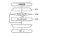
- FIG. 21 is a diagram showing a processing flow of this addition processing.
- the touch detection unit 15 compares the latest reference value S (i, j) with the initial reference value S 0 (i, j) set in step ST0a ( Step ST42) When these do not match, the addition value B is added to the difference value D (i, j) calculated in step ST3 (step ST43) for all intersection positions (i, j). (Step ST41).
- the initial reference value S 0 (i, j) needs to be stored in a frame memory different from the two frame memories FM0 described above.
- FIG. 22 is a diagram for explaining the effect of this modification.
- FIG. 22 (a) schematically shows a state in which five fingers F1 to F5 touch the touch surface 5a at the same time in a state where the wide convexity generation area AA by the back support exists in the touch surface 5a. It is shown in.
- FIG. 22B schematically shows the difference value D (i, j) calculated in step ST3 at that time
- FIG. 22C shows the difference value D () after further passing through step ST40.
- i, j) are schematically shown.
- FIG. 22 shows a state in which the calibration has already been sufficiently performed and the wide convex portion due to the back surface does not appear in the difference value D (i, j).
- the indicator convex portions corresponding to the fingers F3, F4 touching the area AA are compared to the indicator convex portions corresponding to the fingers F1, F2, F5 touched outside the area AA. It will be small. This is because the reference value S (i, j) is increased in the area AA as a result of the calibration.
- the difference value D (i, j) is raised by the addition value B in the area AA as shown in FIG.
- the indicator convex portions corresponding to the fingers F3, F4 are raised to the same level as the indicator convex portions corresponding to the fingers F1, F2, F5.
- the reference value S (i, j) is increased by the calibration process, a high indicator convex portion is obtained as in the case where the reference value S (i, j) is not increased. Is possible.
- step ST13 in FIG. 14 when there is no difference value D (i, j) calculated in step ST3 in FIG. 13 that exceeds the touch detection threshold T2 (negative determination in step ST4), step ST13 in FIG.
- the area SQ calculated in step S1 is less than the palm determination value SQ0 (negative determination in step ST15)
- the centroid GCur calculated in step ST13 in FIG. 14 is not the same as the centroid GCur calculated in the immediately preceding loop (in step ST18). (No determination) and when the variable count is less than the calibration timer Count0 (No determination in step ST21), the calibration is not performed, but the calibration may be performed also in these cases. . This will be specifically described below.
- FIG. 23 is a diagram showing another modification of the touch detection process shown in FIG. As shown in the figure, in this modification, the calibration process (step ST50) is also inserted after the step ST5. In addition, a calibration coefficient a used in the calibration process is added as one of the values set first (step S0b).
- the reference value S (i, j) stored in the frame memory FM0 shown in FIG. 2 is updated by the following equation (7).
- the calibration coefficient a is smaller than the calibration coefficient A used in step ST8.
- FIG. 24 is a diagram showing another modification of the coordinate derivation process shown in FIG. As shown in the figure, in this modification, between step ST11 and step ST12, a process for determining whether or not the touch detection threshold T1 is greater than or equal to a variable T1last (step ST60) and a negative in step ST60. When the determination result is obtained, a process (step ST61) for resetting the touch detection threshold value T1 is inserted. Further, a process for setting the touch detection threshold T1 in the variable T1last is inserted in the final stage of the coordinate derivation process (step ST62).
- the resetting of the touch detection threshold T1 in step ST61 is a process for resetting a value larger than the value set in step ST11 to the touch detection threshold T1, and specifically, as shown in the following equation (8).
- the touch detection threshold value T1 is reset to a value obtained by adding (1 ⁇ E) times the variable T1last to E times the touch detection threshold value T1.
- E is a constant (update coefficient) that satisfies 0 ⁇ E ⁇ 1, and is initialized together with other values in step ST0 shown in FIG.
- the touch detection threshold value T1 calculated in step ST11 is necessarily smaller than the variable T1last, so the touch detection threshold value T1 calculated by equation (8) is larger than the value set in step ST11. It must be a large value.
- FIG. 25 is a diagram for explaining the effect of this modification.
- (A), (c), (e), and (g) are cross-sectional views depicting how the deflection of the touch surface 5a is gradually eliminated after the touch surface 5a is pressed by the finger 8.
- (a) is a state where the touch surface 5a is pressed by the finger 8
- (c) is a state where the deflection of the touch surface 5a continues even after the finger 8 leaves the touch surface 5a
- (e) The state in which the deflection is still being eliminated and (g) shows the state in which the deflection is completely eliminated.
- FIGS. 25B, 25D, 25F, and 25H show the states of the difference values D (i, j) corresponding to FIGS. 25A, 25C, 25E, and 20G, respectively.
- the touch detection threshold value T1 illustrated in each drawing indicates the value calculated in step ST11 in FIG. 24 (before resetting in step ST61).
- step ST14 the determination result in step ST12 becomes negative, and the detected coordinates are set as the host. The process of outputting to the CPU (step ST14) is not executed.
- the detected coordinates continue to be output to the host CPU even though the indicator convex portion does not exist.
- the detected coordinates output in this way are merely the center of gravity of the upper end portion of the wide convex portion due to the slanted line in FIG. 25D, that is, “deflection”, and do not indicate the position of the indicator. From this point of view, it is the result of false detection.
- the specific value of the constant E is preferably determined experimentally so that the above effect can be obtained, but is preferably set to a value such as 0.1 or 0.5.
- the touch detection device 1 it is determined whether or not the newly calculated center of gravity GCur and the immediately preceding center of gravity GCur completely match (step S18 in FIG. 14), and the state in which the result matches is the calibration timer.
- the calibration process is started when the time indicated by Count0 continues, but this process is an example, and when the center of gravity GCur has not moved beyond a predetermined range within a predetermined time, The calibration process may be started.
- it may be determined that the newly calculated center of gravity GCur is included in a predetermined range centered on the immediately preceding center of gravity GCur.
- the predetermined range in this case is, for example, an actual size on the touch surface 5a, a range within a circle of 5 mm in diameter or a rectangle of 5 mm square centered on the immediately preceding center of gravity GCur, and more preferably on the touch surface 5a. It is preferable to set an actual size within a circle of 1.5 mm in diameter or a rectangle of 1.5 mm square centered on the immediately preceding center of gravity GCur.
- the present invention is particularly effective for an air gap type touch detection device, but can also be applied to touch detection devices other than the air gap type. Therefore, the present invention can be used for general purposes even when the mounting environment of the touch sensor is not known in advance.
- the maximum value, the detection value, and the like have been described as taking positive values. However, it is also possible to explain that these take negative values. It goes without saying that the magnitude relationship of is opposite to that described above.
- the maximum value is detected when the capacitance change due to the proximity of the finger is detected as positive, and the capacitance change due to the proximity of the finger is expressed as a negative amount as a decrease in the detected current. In this case, it corresponds to detecting the minimum value.
Landscapes
- Engineering & Computer Science (AREA)
- General Engineering & Computer Science (AREA)
- Theoretical Computer Science (AREA)
- Human Computer Interaction (AREA)
- Physics & Mathematics (AREA)
- General Physics & Mathematics (AREA)
- Position Input By Displaying (AREA)
Abstract
【課題】指示体によって生ずる指示体凸部より幅の広いワイド凸部が生じた場合であっても、指示体凸部のみを適切に検出する。 【解決手段】複数のセンサ電極を含む静電容量方式のタッチセンサのコントローラにより実行されるタッチ検出方法であって、複数のセンサ電極の交差位置ごとに、指示体とタッチセンサ間の静電容量に対応する差分値D(i,j)を取得するステップと、差分値D(i,j)の最大値D(imax,jmax)を取得するステップST10と、固定値であるか、又は、最大値D(imax,jmax)が大きいほど小さくなる値である減算値Rを最大値D(imax,jmax)から減じた値にタッチ検出閾値T1を決定するステップST11と、タッチ検出閾値T1を基準として、交差位置ごとの差分値D(i,j)に基づいて指示体の位置を示す重心GCurを導出するステップST13とを含む。
Description
本発明はタッチ検出方法、タッチ検出装置、及びタッチセンサコントローラに関し、特に、対象物の近接に伴うセンサ電極間の静電容量の変化を検出するタッチ検出方法、タッチ検出装置、及びタッチセンサコントローラに関する。
静電容量方式のタッチセンサは、それぞれY方向に延在する複数のX電極と、それぞれX方向に延在する複数のY電極とが交差して配置された構成を有しており、例えば、Y電極に対して所定の信号を入力し、各X電極から順にこの信号を取り出す、という処理をすべてのY電極に対して順に繰り返すように構成される。タッチセンサのタッチ面に指などの指示体が近づくと、その近傍にあるX電極及びY電極との間に静電容量が生じ、この静電容量を通じてX電極に流れていた電流の一部が指示体方向に電流が吸い取られるようになるため、X電極から取り出される信号の振幅が小さくなる。静電容量方式のタッチセンサは、この振幅の変化から静電容量の増加を検出し、静電容量が閾値以上となっている領域の重心を示す座標を、指示体の位置座標として導出するよう構成される。
また、タブレット端末に代表されるタッチ検出装置は、液晶表示装置の表示面上に静電容量方式のタッチセンサを配置することによって構成されることが一般的であるが、この配置の具体的な方法として、液晶表示装置の表示面とタッチセンサの間に空間(エアーギャップ)を設ける例が知られている。この場合、タッチセンサと液晶表示装置の間の固定は、表示面の縁部に配置されるスペーサ等によって実現される。このようなエアーギャップを有するタッチ検出装置を、以下では「エアーギャップ型」と称する。
エアーギャップ型のタッチ検出装置は、モアレの発生を避けられる、液晶表示装置上に接着剤層を設ける工程を省略できる、故障したタッチセンサの交換が容易であるなどの点で有利である一方、指などの指示体によってタッチ面が強く押された場合などに、タッチセンサに「たわみ」が生じてしまうという弱点も有している。「たわみ」が生じてタッチセンサが液晶表示装置の表示面に近づくと、その部分においても上述した静電容量が増加するため、非常に広い領域にわたって指示体が検出されたのと同じことになる。こうして検出される広い領域の重心は指示体による指示位置と必ずしも一致しないため、たわみの発生によって位置検出の精度が下がってしまうことになる。
特許文献1には、タッチ閾値を超える静電容量を出力した電極の数が所定数以上である場合に「たわみ」が生じたと判定し、その場合に接触位置の算出をキャンセルするように構成したエアーギャップ型のタッチ検出装置において、タッチパネルと物体との接触位置を連続して出力した回数である連続タッチダウンカウントが所定の閾値よりも大きい場合に、たわみ判定処理をキャンセルすることが開示されている。「たわみ」の原因が指示体によるタッチ面の強い押下である場合、これを「たわみ」として検出してしまうと指示体の位置検出も行えないことになるが、特許文献1に開示の技術によれば、このような場合にも指示体の位置検出が行えるようになる。ただし、特許文献1の技術は、「たわみ」があっても指示体の位置を検出できるようにする、というものに過ぎず、指示体の位置座標を導出する方法自体は上述した従来の方法と同様であるので、「たわみ」が発生している場合の位置座標の導出精度は、従来と同様、あまり高いものとはならない。
また、「たわみ」とは関係ないが、特許文献2には、指示体を検出するために設ける静電容量の閾値を、指示体の種類によって動的に変更する技術が開示されている。この技術では、直前の所定数フレームのそれぞれにおいて得られた静電容量の検出値の平均値に所定の係数(例えば1/2)を乗ずることにより、閾値を算出している。これによれば、静電容量の検出値が互いに異なる複数種類の指示体を、好適に検出できるようになる。
特許文献3には、静電容量の検出値(RAW値)とベースライン値の差分値(DIFF値)に基づいて指示体の検出を行うタッチ検出装置が開示されている。このタッチ検出装置は、ある程度以上の面積の領域で差分値が閾値を超えた場合に「ラージオブジェクトフラグ」を立て、「ラージオブジェクトフラグ」が立っている場合に座標算出処理を行わないようにすることにより、掌等の大きな物体が検出されないようにする機能と、「ラージオブジェクトフラグ」の立った状態が所定時間以上継続した場合に、RAW値をベースライン値に設定する処理(キャリブレーション)を行うことで、それ以降、掌等の大きな物体の近接による静電容量の変化が差分値に反映されないようにする機能とを有している。
「たわみ」が発生した場合に位置検出の精度が下がってしまう、というエアーギャップ型のタッチ検出装置の課題について、より詳しく説明する。
図26(a)は、エアーギャップ型のタッチ検出装置において「たわみ」が発生していない場合の静電容量C(i,j)の座標(i,j)による変化を示す模式図である。一方、図26(b)は、「たわみ」が発生している場合の静電容量C(i,j)の座標(i,j)による変化を示す模式図である。いずれの図においても、中央付近に現れている小さな凸部が指示体による凸部を表している。
図26(a)(b)を比較すると理解されるように、「たわみ」が発生している場合の静電容量Cのピーク値P2は、「たわみ」が発生していない場合の静電容量Cのピーク値P1に比べてかなり大きな値となっている。これは、「たわみ」が発生している場合、「たわみ」によって生ずる幅広の凸部の上に指示体による凸部が生ずる形となるためである。
「たわみ」が発生していない場合に指示体の位置を適切に検出するためには、図26(a)に例示するように、静電容量Cの閾値Tをピーク値P1よりも小さな値に設定する必要がある。こうすることで、図26(a)に示すように、タッチセンサによって検出される領域S1が指示体による凸部の位置とよく一致することから、指示体の位置として領域S1の重心を導出することで、適切に指示体の位置検出を行うことが可能になる。
一方、こうして決定される閾値T(ピーク値P1よりも小さな値の閾値T)を用いると、図26(b)のように「たわみ」が発生している場合に、位置検出の精度が低下する。すなわち、図26(b)から理解されるように、この場合にタッチセンサによって検出される領域S2は、指示体ではなく「たわみ」による凸部の位置と一致する。したがって、領域S2の重心を導出しても、単に「たわみ」の中央位置が得られるに過ぎず、指示体の位置は得られない。つまり、指示体の位置を正しく検出することができないのである。
このような課題に対し、例えば特許文献2のように、静電容量の検出値の平均値に所定の係数(例えば1/2)を乗ずることにより、閾値を動的に変更することが考えられる。しかしながら、図26から明らかなように、このように閾値を動的に変更するとしても、「たわみ+指示体」による凸部の中央位置の検出に適した閾値が得られるだけで、指示体による凸部のみの中央位置を検出可能とすることは困難である。
以上の課題は、エアーギャップ型のタッチ検出装置において「たわみ」が発生した場合だけでなく、掌によるタッチ等の他の理由により、指示体による凸部より幅の広い凸部が生ずる場合に広く生ずる課題である。したがって、本発明の目的の一つは、指示体による凸部より幅の広い凸部が生じた場合であっても、指示体による凸部のみを適切に検出できるタッチ検出方法、タッチ検出装置、及びタッチセンサコントローラを提供することにある。
また、エアーギャップ型のタッチ検出装置には、「たわみ」にヒステリシスが生ずるという課題がある。すなわち、例えば指示体によるタッチによって生じた「たわみ」は、指示体がタッチ面を離れた後にも直ちには解消されず、ある程度の時間(例えば数ミリ秒)をかけて徐々に解消されていく。その間にもタッチ検出装置による位置検出は継続されるので、「たわみ」による凸部が十分に小さくなるまでの間、「たわみ」による凸部の重心が指示体の位置として導出されてしまうことになる。
したがって、本発明の目的の他の一つは、「たわみ」のヒステリシスによって生ずる指示体の位置の誤検出を防止できるタッチ検出方法、タッチ検出装置、及びタッチセンサコントローラを提供することにある。
さらに、本願の発明者は、タッチ検出装置は片手で保持可能なサイズに形成されることも多いが、後述する図3(e)のような持ち方により片手で持った状態でエアーギャップ型のタッチ検出装置を使用すると、ユーザの手を通じてタッチ検出装置の裏面に圧力が加わり、掌でタッチ面にタッチした場合と同様の幅広の凸部が検出される場合があることを新たに発見した。以下では、このようなタッチ検出装置の持ち方を「背面支持」と称する。
特許文献3のタッチ検出装置のように、スキャンやコピーを実行する多機能周辺装置の操作部(同文献図19、図21参照)などで利用されるタッチ検出装置ではこのような背面支持はおこりえないが、近年薄型化と軽量化の顕著なタブレット端末等では背面支持は頻繁に行われる。特許文献3に記載されるキャリブレーションでは、この背面支持によって生ずる幅広の凸部も、タッチ面に掌がタッチしたことによって生ずる幅広の凸部も、区別なく差分値からキャンセルされることになる。
ここで、いわゆるタブレット端末などの汎用のタッチ検出装置においては、特許文献3に記載されているような、メニュー選択など操作が限定的であることの多い多機能周辺装置の操作部であるタッチ検出装置とは異なり、上記のようなキャリブレーションを行うことはあまり好ましくないとされる。
元来、キャリブレーションを行うということは、現在検出されている静電容量の検出値を基準状態とするということである。タッチを行っている最中にキャリブレーションが実行されると、基準状態が検出値に追従することになる。したがって、本来的には、キャリブレーションを行いながらタッチの検出を実行することは背反な関係である。例えば、机の上に置かれた紙に筆記具で描画を行うのと同じように、所謂タッチペンやパッシブペンと呼ばれるような指とは異なる位置指示器をタブレット端末上で利用しようとすると、位置指示器を把持した掌の側面が初めにタッチ面上に載せられることになる。ここで掌の側面により生じた静電容量の状態が維持されたことを持ってキャリブレーションを実行してしまうと、さてユーザが掌の側面を載せた状態から位置指示器を使ってタブレット端末による入力を開始しても、その瞬間は指示器(あるいは人差し指)によるが検出できなくなる可能性がある。これが、汎用のタッチ検出装置において、キャリブレーションを行うことはあまり好ましくないとされる理由である。
しかしながら、「背面支持」の場合は、掌の側面が机に置かれたタブレットに載せられ今からタッチ入力が期待される上記のような状況に比して、即座にタッチペンの使用を開始されることは経験上少ない。例えば、掌の側面が置かれている状況とは異なり、背面支持している場合には動画像などを閲覧していたりしている利用形態があるためである。従って、「背面支持」による凸部については、掌の側面が載せられている場合に比して、キャリブレーションを行ってキャンセルしてしまうことが好ましい状況が多い。しかしながら、従来、背面支持によって生ずる幅広の凸部を選択的に抽出する方法がなく、その結果、従来のタッチ検出装置には、背面支持によって生ずる幅広の凸部のみを対象としてキャリブレーションを実行することができないという課題があった。
したがって、本発明の目的の他の一つは、背面支持によって生ずる幅広の凸部のみを対象としてキャリブレーションを実行することができるタッチ検出方法、タッチ検出装置、及びタッチセンサコントローラを提供することにある。
本発明の一側面によるタッチ検出方法は、複数のセンサ電極を含む静電容量方式のタッチセンサのコントローラにより実行されるタッチ検出方法であって、前記複数のセンサ電極の交差位置ごとに、指示体と前記タッチセンサ間の静電容量に対応する検出値を取得するステップと、前記交差位置ごとの前記検出値の中の最大値を取得するステップと、固定値であるか、又は、前記最大値が大きいほど小さくなる値である減算値を前記最大値から減じた値に第1の閾値を決定するステップと、前記第1の閾値を基準として、前記交差位置ごとの検出値に基づいて前記指示体の位置を導出するステップとを含むタッチ検出方法である。
なお、上記タッチ検出方法において、前記第1の閾値が低下している場合に、前記第1の閾値を決定するステップで決定された値よりも大きな値を前記第1の閾値に再設定するステップをさらに備え、前記指示体の位置を導出するステップは、再設定された前記第1の閾値を基準として、前記交差位置ごとの検出値に基づいて前記指示体の位置を導出するよう構成されることとしてもよい。
本発明の他の一側面によるタッチ検出方法は、複数のセンサ電極を含む静電容量方式のタッチセンサのコントローラにより実行されるタッチ検出方法であって、前記複数のセンサ電極の交差位置ごとの基準値を取得するステップと、前記交差位置ごとに、前記静電容量を示す容量値を取得するステップと、前記交差位置ごとに、前記容量値及び前記基準値に基づいて、指示体と前記タッチセンサ間の静電容量に対応する検出値を取得するステップと、対応する検出値が第1の閾値を超える交差位置により示される領域の代表位置を算出するステップと、前記代表位置の移動の有無を判定するステップと、前記移動の有無を判定するステップの判定結果に応じて、前記検出値に近づく方向に前記基準値を較正するキャリブレーションを起動するステップとを含むタッチ検出方法である。
本発明の一側面によるタッチ検出装置は、静電容量方式のタッチセンサを構成する複数のセンサ電極と、前記複数のセンサ電極の交差位置ごとに、指示体と前記タッチセンサ間の静電容量を示す容量値を取得するタッチ検出部と、前記交差位置ごとの前記容量値に基づく値である検出値の中の最大値を取得し、固定値であるか、又は、前記最大値が大きいほど小さくなる値である減算値を前記最大値から減じた値に第1の閾値を決定し、決定した前記第1の閾値を基準として、前記交差位置ごとの検出値に基づいて前記指示体の位置を導出する座標導出部とを含むタッチ検出装置である。
本発明の他の一側面によるタッチ検出装置は、静電容量方式のタッチセンサを構成する複数のセンサ電極と、前記複数のセンサ電極の交差位置ごとの基準値を取得するとともに、前記交差位置ごとに前記静電容量を示す容量値を取得し、さらに、前記交差位置ごとに、対応する前記容量値から対応する前記基準値を減じてなる差分値を算出するタッチ検出部と、前記差分値又は前記差分値に基づいて取得される検出値が第1の閾値を超える交差位置により示される領域の代表位置を算出するとともに該代表位置の移動の有無を判定し、その判定結果に応じて、前記検出値に近づく方向に前記基準値を較正するキャリブレーションを起動する座標導出部とを含むタッチ検出装置である。
本発明の一側面によるタッチセンサコントローラは、静電容量方式のタッチセンサを構成する複数のセンサ電極とともに用いられるタッチセンサコントローラであって、前記複数のセンサ電極の交差位置ごとに、指示体と前記タッチセンサ間の静電容量を示す容量値を取得するタッチ検出部と、前記交差位置ごとの前記容量値に基づく値である検出値の中の最大値を取得し、固定値であるか、又は、前記最大値が大きいほど小さくなる値である減算値を前記最大値から減じた値に第1の閾値を決定し、決定した前記第1の閾値を基準として、前記交差位置ごとの検出値に基づいて前記指示体の位置を導出する座標導出部とを含むタッチセンサコントローラである。
本発明の他の一側面によるタッチセンサコントローラは、静電容量方式のタッチセンサを構成する複数のセンサ電極とともに用いられるタッチセンサコントローラであって、前記複数のセンサ電極の交差位置ごとの基準値を取得するとともに、前記交差位置ごとに前記静電容量を示す容量値を取得し、さらに、前記交差位置ごとに、対応する前記容量値から対応する前記基準値を減じてなる差分値を算出するタッチ検出部と、前記差分値又は前記差分値に基づいて取得される検出値が第1の閾値を超える交差位置により示される領域の代表位置を算出するとともに該代表位置の移動の有無を判定し、その判定結果に応じて、前記検出値に近づく方向に前記基準値を較正するキャリブレーションを起動する座標導出部とを含むタッチセンサコントローラである。
本発明の一側面によれば、最大値を検出した後、その最大値から上記減算値を減算した値によって、位置導出の基準となる第1の閾値を決定しているので、指示体による凸部(以下、「指示体凸部」と称する)より幅の広い凸部(以下、「ワイド凸部」と称する)が生じた場合であっても、指示体凸部のみを適切に検出することが可能になる。
なお、減算値は固定値としてもよいが、検出した最大値が大きいほど小さくなる値であるとすることがより好適である。これは、ワイド凸部が高いほど検出される最大値が大きくなる一方で、ワイド凸部が高いほど、その上に位置する指示体凸部の高さ(ワイド凸部の頂上からの高さ)が小さくなる傾向があるからである。
また、本発明の一側面の変形例によれば、第1の閾値が低下している場面で第1の閾値をより大きな値に再設定しているので、第1の閾値の低下を遅らせることができる。したがって、このような場面で第1の閾値を基準とする指示体の位置の導出が行われなくなるので、「たわみ」のヒステリシスによって生ずる指示体の位置の誤検出を防止することが可能になる。
また、本発明の他の一側面によれば、代表位置が移動していない場合にのみキャリブレーションを起動するようにしているので、背面支持によって生ずるワイド凸部のみをキャリブレーションの対象とすることが可能になる。なお、この一側面は、背面支持を行うことによってワイド凸部が生じること、並びに、背面支持を行うことによって生じるワイド凸部は、背面支持をした場合にはタッチ検出装置自体は大きくぐらつくことがあるものの、背面を指示する支点(複数の指)とタッチ検出装置との相対的な位置関係が変化しないため、タッチ面に掌がタッチしたことによって生ずるワイド凸部に比べて時間が経過してもほとんど移動せず、したがって、この移動の有無を検出することによってこれらのワイド凸部を区別できる、という新たな知見に基づく発明である。
また、本発明の他の一側面によれば、ワイド凸部が背面支持によって生じたものと判定された場合にキャリブレーションを実行するので、動画像を見ている場合など背面支持をしばらく持続するような場合に、タッチの検出を停止させることが可能になり、タッチ検出に伴う計算処理ならびに、ホストCPUに対する無効フラグが付いている情報の通知自体や割り込み処理等を停止することが可能となる。
以下、添付図面を参照しながら、本発明の好ましい実施の形態について詳細に説明する。
図1は、本実施の形態によるタッチ検出装置1の断面図であり、図2は、タッチ検出装置1の機能ブロックを示す略ブロック図である。
タッチ検出装置1は、図1に示すように、略直方体の上蓋なしの箱状に形成された筐体2と、表示面3aを上に向けた状態で筐体2の内部に収められた表示装置3と、表示面3aの上方に配置された透明のカバーパネル5と、カバーパネル5の下面(表示面3aとの対抗面)に貼り付けられたタッチセンサ6と、カバーパネル5及びタッチセンサ6を支えるスペーサ4とを備えて構成される。なお、スペーサ4は、筐体2の縁部の全周にわたって配置される。また、タッチ検出装置1は、図2に示すように、タッチセンサコントローラ10、記憶部20、及びホストCPUも備えて構成される。本実施の形態によるタッチ検出方法は、このタッチセンサコントローラ10によって実行される。
図1に示すように、タッチ検出装置1においては、カバーパネル5の上面がタッチ面5aを構成する。タッチ検出装置1に対する入力操作は、このタッチ面5a上で図示した指8などの指示体を移動させることによって実行される。なお、タッチセンサ6用の指示体としては、図示した指8の他、静電容量方式に対応した電子ペンなども使用できるが、以下では説明の簡単のため、指示体として指8を使用するものとして説明する。また、タッチセンサ6と表示面3aとは密着しておらず、これらの間には一定の空間(エアーギャップ7)が設けられている。つまり、タッチ検出装置1は、上述したエアーギャップ型のタッチ検出装置である。
表示装置3は、図2に示したホストCPUの制御に基づき、文字や画像を表示するための装置である。表示装置3として、具体的には液晶ディスプレイや有機ELディスプレイを用いることが好適であるが、これら以外のディスプレイにより表示装置3を構成することも可能である。
タッチセンサ6は静電容量方式のタッチセンサであり、図2に示すように、それぞれY方向(図1に示したタッチ面5a内の一方向)に延在し、X方向(図1に示したタッチ面5a内でY方向に直交する方向)に等間隔で配置された複数のX電極6xと、それぞれX方向に延在し、Y方向に等間隔で配置された複数のY電極6yとが交差して配置された構成を有して構成される。これらX電極6x及びY電極6yは、タッチセンサ6のセンサ電極を構成する。各X電極6x及び各Y電極6yはいずれもITO透明導電性フィルムなどの透明な導電材料によって構成されており、したがってタッチ検出装置1のユーザは、タッチ面5aを通して表示装置3の表示面3aを見ることができる。タッチ面5aに指8が接触すると、指8と、その近傍にあるX電極6x及びY電極6yとの間に静電容量が発生する。図2に示したタッチセンサコントローラ10は、この静電容量の変化を利用して、タッチ面5a上における指8の位置を検出するように構成される。この点については、後ほど再度より詳しく説明する。
カバーパネル5は、例えばガラスやプラスチックなどの、タッチ面5aに対する押圧力に対して高い強度を有する透明材料によって構成される。ただし、ユーザが強めにタッチ面5aを押下すると、カバーパネル5は、タッチセンサ6とともに表示面3a方向にたわむ。このたわみは上述した静電容量に影響を及ぼすので、タッチセンサコントローラ10による指8の検出にも影響を及ぼす。この点についても、後ほど再度より詳しく説明する。
タッチセンサコントローラ10は、図2に示すように、発振器11と、マルチプレクサ12,13と、アナログデジタル変換器(A/D)14と、タッチ検出部15と、座標導出部16とを有して構成される。
発振器11は、所定周波数の信号を発振する回路である。また、マルチプレクサ12は、複数のX電極6xを所定の時間間隔で1つずつ順次選択し、選択したX電極6xに発振器11を接続する役割を果たす回路である。このマルチプレクサ12の働きにより、発振器11が出力した信号は、複数のX電極6xのそれぞれに順に供給されることになる。X電極6xに供給された信号は、各Y電極6yとの交差位置(i,j)を通じて、各Y電極6yに供給される。ここで、i,jはそれぞれX電極6x及びY電極6yの通番を示す自然数であり、iとjの組み合わせ(i,j)により、タッチ面5a上における各交差位置の座標が示される。i,jそれぞれの最大値は、図2に示すようにM,Nである。
マルチプレクサ13は、複数のY電極6yを所定の時間間隔で1つずつ順次選択し、選択したY電極6yをアナログデジタル変換器14の入力端に接続する役割を果たす回路である。アナログデジタル変換器14は、各Y電極6yから供給された信号に標本化及び量子化を施すことによってデジタル信号を生成し、生成したデジタル信号をタッチ検出部15に供給する機能を有する。
いずれかの交差位置(i,j)の近くに指8が接近していると、その交差位置(i,j)の近傍にあるX電極6x及びY電極6yと指8との間に静電容量が生じて人体方向に信号が吸い取られる。その結果、そのY電極6yからアナログデジタル変換器14に供給される信号の振幅が小さくなり、それがデジタル信号の値に反映される。タッチ検出部15は、こうしてデジタル信号の値に反映される振幅の変化に基づき、交差位置(i,j)ごとに、指8とタッチセンサ6間の静電容量を示す容量値C(i,j)を取得するよう構成される。なお、タッチ検出部15の具体的な回路構成としては、例えばプログラマブルロジックコントローラのようなハードウェア回路が用いられる。
タッチ検出部15はまた、容量値C(i,j)を差分値D(i,j)(指8とタッチセンサ6間の静電容量に対応する検出値)に変換する機能も有する。具体的に説明すると、記憶部20には、図2に示すように、交差位置(i,j)ごとの基準値S(i,j)を格納するフレームメモリFM0と、交差位置(i,j)ごとの差分値D(i,j)を格納するフレームメモリFM1とが設けられる。タッチ検出部15は、交差位置(i,j)ごとに、フレームメモリFM0から基準値S(i,j)を読み出し、次の式(1)により、読み出した基準値S(i,j)を対応する容量値C(i,j)から減算する処理を行う。そして、この減算の結果として得られる数値を、各交差位置(i,j)に対応する差分値D(i,j)としてフレームメモリFM1に格納するよう構成される。

タッチ検出部15は、以上の機能の他に、予め記憶しているタッチ検出閾値T2(第2の閾値。後掲する図13を参照)を上回る差分値D(i,j)があるか否かを判定し、あると判定した場合にのみ座標導出部16に座標導出を行わせる機能や、座標導出部16の指示に基づいて基準値S(i,j)のキャリブレーションを行う機能なども有するが、これらの詳細については、後ほど図13及び図14を参照しながら説明する。
座標導出部16は、フレームメモリFM1に記憶される複数の差分値D(i,j)の中の最大値を取得し、この最大値から減算値Rを減ずることによってタッチ検出閾値T1(第1の閾値)を算出する機能と、算出したタッチ検出閾値T1を基準として、交差位置(i,j)ごとの差分値D(i,j)に基づいて指8の位置を導出する機能とを有する。また、座標導出部16はさらに、差分値D(i,j)がタッチ検出閾値T1を超える1又は複数の交差位置(i,j)により示される領域の重心GCur(代表位置)を算出するとともに、この重心GCurの移動の有無を判定し、その判定結果に応じて、差分値D(i,j)に近づく方向に各基準値S(i,j)を較正するためのキャリブレーション処理を起動する機能も有する。座標導出部16は、例えばMPUのような集積回路によって構成されており、外部から供給されるプログラムを実行することによって、上記3つの機能を含む各機能を実現するよう構成される。
座標導出部16の機能の詳細についても、後ほど図13及び図14を参照しながら別途説明する。
以上、タッチ検出装置1の概要について説明した。次に、フレームメモリFM1に格納される差分値D(i,j)について、ユーザの手(指8を含む)とタッチ検出装置1の位置関係の状態ごとに、具体的な例を挙げて説明する。
図3(a)~図3(f)は、ユーザの手とタッチ検出装置1の位置関係の状態を示す模式図である。なお、これらの図では、タッチ検出装置1の断面図を少し簡略化して描いている。図3(a)は、タッチ検出装置1の近傍にユーザの手が存在しない状態(状態S0)を示している。また、図3(b)は、指8によってタッチ面5aの中央付近が押下されている状態(状態S1)を示している。図3(c)は、指8によってタッチ面5aの端部付近が押下されている状態(状態S2)を示している。図3(d)は、拳8aによってタッチ面5aの中央付近が押下されている状態(状態S3)を示している。図3(e)は、掌8bによってタッチ検出装置1が背面支持されている状態(状態S4)を示している。図3(f)は、掌8bによってタッチ検出装置1が背面支持されつつ、指8によってタッチ面5aの中央付近が押下されている状態(状態S5,S6)を示している。
図4は、図3(a)に示した状態S0における差分値D(i,j)の一例を示す図である。なお、図4には、X電極6xがTX00~TX35の36個、Y電極6yがRX00~RX62の63個それぞれ設けられる例を示しており、図4(a)では、奥行き軸がX座標、横軸がY座標、縦軸が差分値D(i,j)をそれぞれ表し、図4(b)では、横軸がY座標、縦軸が差分値D(i,j)をそれぞれ表している。図4(b)は、図4(a)を奥行き方向に見た図となっている。これらの点は、後に参照する図5~図11についても同様である。ただし、図5については、差分値D(i,j)に代えて基準値S(i,j)を用いている。
図4に示すように、状態S0における差分値D(i,j)はタッチ面5a上のどの位置においてもほぼゼロであり、これは、タッチ検出装置1の近傍にユーザの手を含む指示体が何も存在しないことを示している。ただし、この場合においても、容量値C(i,j)は座標ごとに異なっているのが通常であり、図4に示すような一様な差分値D(i,j)を得るためには、予め基準値S(i,j)の調整を行っておく必要がある。図5には、こうして調整された基準値S(i,j)の一例を示している。
図6は、図3(b)に示した状態S1における差分値D(i,j)の一例を示す図である。同図においてタッチ面5aの中央付近に生じている凸部は、タッチ面5aの中央付近に位置している指8とタッチセンサ6との間に生ずる静電容量を反映した指示体凸部である。図6では、指示体凸部の周囲においても差分値D(i,j)が大きくなっているが、これは、タッチセンサ6のたわみによって生ずるワイド凸部である。すなわち、図3(b)に例示するように、指8の押圧力によっては、タッチ面5aの押下によってタッチセンサ6にたわみが生ずる場合がある。このたわみによって生ずるタッチセンサ6の位置の変化が大きいほど、タッチ検出部15によって検出される容量値C(i,j)が大きくなるため、図6のように、押下点の付近にワイド凸部が生ずることになる。
本実施の形態によるタッチ検出装置1の特徴の一つは、このようにワイド凸部が生じている場合であっても、指示体凸部のみを適切に検出することを実現する点にある。そのために、本実施の形態では、差分値D(i,j)の最大値から減算値Rを減ずることによって得られるタッチ検出閾値T1を利用する。詳細については、後ほど図13及び図14を参照しながら説明する。
図7は、図3(c)に示した状態S2における差分値D(i,j)の一例を示す図である。同図においてタッチ面5aの端部付近に生じている凸部は、タッチ面5aの端部付近に位置している指8とタッチセンサ6との間に生ずる静電容量を反映した指示体凸部である。この指示体凸部は図6の指示体凸部に比べて小さいが、これは、タッチ面5aの端部付近でタッチセンサ6の感度が弱いことによるものである。また、この場合にも指示体凸部の周囲で差分値D(i,j)が大きくなっているが、これは図6の場合と同様、タッチセンサ6のたわみによって生ずるワイド凸部である。押下点がタッチ面5aの端部であるため、指8による指示体凸部は、たわみによるワイド凸部の端部付近に位置している。
図8は、図3(d)に示した状態S3における差分値D(i,j)の一例を示す図である。同図においては、指示体凸部は生じておらず、相対的に広いワイド凸部の上に相対的に狭いワイド凸部が生じている。後者のワイド凸部は拳8aとタッチセンサ6の間に発生する静電容量を反映したものであり、前者のワイド凸部はタッチセンサ6のたわみによって生じたものである。
図9は、図3(e)に示した状態S4における差分値D(i,j)の一例を示す図である。同図においても指示体凸部は生じておらず、ワイド凸部が1つ生じている。このワイド凸部は背面支持によって生じたものであり、図8に示した拳8aによるワイド凸部や、タッチ面5aの押下によって生じたたわみによるワイド凸部と比べると、その重心が移動しないという特徴を有している。
この特徴について、具体的な例を挙げて説明する。図12は、所定時間にわたる凸部の重心の移動の軌跡を示したものであり、図12(a)は図3(e)に示した状態S4で検出されるワイド凸部の重心の移動の軌跡を、図12(b)は図3(d)に示した状態S3で検出されるワイド凸部の重心の移動の軌跡を、それぞれ示している。これらの図から理解されるように、背面支持によって生ずるワイド凸部の重心は、拳8aによって生ずるワイド凸部の重心に比べると、ほとんど移動していない。このように、背面支持によって生ずるワイド凸部は、重心がほとんど移動しないという特徴を有している。
本実施の形態によるタッチ検出装置1の特徴の他の一つは、このような背面支持によって生ずるワイド凸部の特徴を利用して、背面支持によって生ずるワイド凸部のみをタッチ検出部15が行うキャリブレーション処理の対象とできる点にある。その詳細については、後ほど図13及び図14を参照しながら説明する。
図10及び図11はそれぞれ、図3(f)に示した状態S5,S6における差分値D(i,j)の一例を示す図である。状態S5はタッチ検出部15がキャリブレーション処理を実行する前の状態であり、状態S6はタッチ検出部15がキャリブレーション処理を実行した後の状態である。図10及び図11においてタッチ面5aの中央付近に生じている凸部は、タッチ面5aの中央付近に位置している指8とタッチセンサ6との間に生ずる静電容量を反映した指示体凸部である。なお、図10と図11とでは指示体凸部の位置が異なっているが、これは測定の都合によるものであり、本質的な違いではない。
図10では、指示体凸部の周囲に、図9に示したものと同じ、背面支持によるワイド凸部が現れている。タッチ検出部15が行うキャリブレーション処理はこのワイド凸部をキャンセルするためのものであり、キャリブレーション処理の実行後には、図11に示すように、背面支持によるワイド凸部が消え、指示体凸部のみが現れるようになる。キャリブレーション処理の詳しい内容についても、後ほど図13及び図14を参照しながら説明する。
以上、図2に示したフレームメモリFM1に格納される差分値D(i,j)の具体例を説明した。次に、図13及び図14を参照しながら、タッチ検出部15及び座標導出部16の機能について、詳細に説明する。
図13は、タッチ検出部15が行うタッチ検出処理の処理フローを示す図である。このタッチ検出処理では、まず初めに、各種の値がタッチ検出部15に設定される(ステップST0)。ここで設定される値には、初期基準値S0(i,j)、タッチ検出閾値T2、減算値R、パーム判定値SQ0、較正係数A、較正タイマーCount0が含まれる。
ここで、図2に示したフレームメモリFM0(基準値S(i,j)を格納するフレームメモリ)は実際には2つ用意されており、タッチ検出部15は、後述するメインループを繰り返す都度この2つを交互に選択し、後述するステップST3では、選択した一方のフレームメモリFM0から基準値S(i,j)を読み出し、後述するステップST3では、他方のフレームメモリFM0に基準値S(i,j)を書き込むよう構成される。以下では、基準値SA(i,j)、基準値SB(i,j)という書き方をする場合があるが、基準値SA(i,j)は、選択した一方のフレームメモリFM0から読み出された基準値S(i,j)を示し、基準値SB(i,j)は、他方のフレームメモリFM0に書き込まれる基準値S(i,j)を示す。初期基準値S0(i,j)は基準値S(i,j)の初期値であり、最初に選択されるフレームメモリFM0に設定される。図5に示した基準値S(i,j)は、この初期基準値S0(i,j)の一例である。
ステップST0が終了した後、タッチ検出部15は、メインループの処理を開始する(ステップST1)。このメインループは、電源断など外部からの割り込みによって中断されるまで繰り返される。
メインループにおいてタッチ検出部15はまず、図2に示したアナログデジタル変換器14から供給されるデジタル信号を参照することにより、容量値C(i,j)の検出を行う(ステップST2)。次にタッチ検出部15は、図2に示したフレームメモリFM0から基準値SA(i,j)を読み出し、上述した式(1)の計算を行うことにより、交差位置(i,j)ごとに差分値D(i,j)を算出する(ステップST3)。
続いてタッチ検出部15は、算出した差分値D(i,j)の中にタッチ検出閾値T2を超えるものがあるか否かを判定する(ステップST4)。これは本来、算出した差分値D(i,j)に指示体凸部があるか否かを判定することを目的とした処理であるが、タッチ検出閾値T2は通常低めに設定されているため、ステップST4の処理では、指示体凸部だけでなく、図6~図10に示したようなワイド凸部も検出される。
ステップST4の処理において否定的な判定結果が得られた場合、タッチ検出部15は、キャリブレーションフラグをオフにした後(ステップST5)、次のループに移行する。キャリブレーションフラグについては後述する。
一方、ステップST4の処理において肯定的な判定結果が得られた場合、タッチ検出部15は、座標導出部16に座標導出処理を行わせる(ステップST6)。
図14は、座標導出部16が行う座標導出処理の処理フローを示す図である。座標導出部16は、処理を開始するとまず、差分値D(i,j)が最大となるi,jの組(imax,jmax)を取得する(ステップST10)。そして、次の式(2)に従って差分値D(i,j)の最大値D(imax,jmax)から減算値Rを減ずることにより、タッチ検出閾値T1を算出する(ステップST11)。

ここで、このタッチ検出閾値T1は、指示体凸部のみを確実に検出するために利用するものである。したがって、減算値Rは、指示体凸部の高さ(ワイド凸部がある場合には、その頂上からの高さ)に相当する値以下とする必要がある。具体的には、固定値としてもよいが、最大値D(imax,jmax)が大きいほど小さくなる値であるとすることがより好適である。
図15は、減算値Rの好適な決定方法を説明するための図である。図15(a)はワイド凸部がある場合、図15(b)はワイド凸部がない場合をそれぞれ示している。これらの図に示すように、最大値D(imax,jmax)は一般に、ワイド凸部がある場合の方が、ワイド凸部がない場合に比べて大きな値となる。一方、指示体凸部の高さHは一般に、ワイド凸部がない場合の方が、ワイド凸部がある場合に比べて大きな値となる。つまり、最大値D(imax,jmax)と指示体凸部の高さHとは負の相関関係を有している。このことから、減算値Rは、最大値D(imax,jmax)が大きいほど小さくなる値であるとすることが好ましいと言える。
図14に戻る。タッチ検出閾値T1を算出した座標導出部16は、次に、タッチ検出閾値T1とタッチ検出閾値T2を比較する(ステップST12)。そして、タッチ検出閾値T1がタッチ検出閾値T2未満であれば処理を終了し、そうでなければステップST13の処理に移行する。
図16は、ステップST12の意味を説明するための図である。図16(a)は、指8がタッチ面5aをしっかりタッチしているが、たわみまでは生じていない場合、図16(b)は、指8がタッチ面5aを強く押下し、たわみが生じている場合、図16(c)は、指8によるタッチが弱すぎるか、又は、タッチ面5aをタッチしているわけではないが何らかの理由で凸部のようなものが見えている場合をそれぞれ示している。図16(a)(b)に示すように、指8のタッチが原因で凸部が生じている場合、タッチ検出閾値T1はタッチ検出閾値T2より大きな値となる。逆に言えば、減算値Rは、図16(a)のようにワイド凸部がない場合であっても、タッチ検出閾値T1がタッチ検出閾値T2を上回ることとなるような値に設定される。一方、図16(c)に示すように、タッチが弱すぎたり、何らかの理由で凸部のようなものが見えているに過ぎない場合、通常、タッチ検出閾値T1はタッチ検出閾値T2より小さな値となる。図14のステップST12は、このような場合に指示体の位置座標を検出しない(ホストCPUに通知しない)ようにするための処理である。
図14に戻る。ステップST13において座標導出部16は、差分値D(i,j)がタッチ検出閾値T1を上回る領域を抽出し、抽出した領域ごとに、その重心GCur及び面積SQを算出する処理を行う。具体的には、次の式(3)により領域の重心GCurを算出するとともに、領域中に含まれる交差位置(i,j)の数を面積SQとする。ただし、式(3)中のARは、抽出した領域中にあるすべての交差位置(i,j)について加算を行うことを示している。

なお、ここでは重心GCurを代表位置として用いる例を説明するが、代表位置として他の特徴量を用いることも可能である。例えば、領域の中心を代表位置として用いてもよいし、領域中で差分値D(i,j)が最大となる点を代表位置として用いてもよい。また、面積SQについても、ここでは領域中に含まれる交差位置(i,j)の数を面積SQとして用いる例を説明するが、領域の外周により示される図形の面積を幾何学的に算出して面積SQとすることも可能である。
次に座標導出部16は、ステップST13で算出した重心GCurを、検出した指示体の位置としてホストCPU(図2を参照)に出力する(ステップST14)。ここまでの説明から理解されるように、本実施の形態によるタッチ検出装置1では、指示体凸部のみを検出できるように構成したタッチ検出閾値T1を閾値として凸部を検出し、検出した凸部の代表位置としてホストCPUに出力している。したがって、本実施の形態によるタッチ検出装置1によれば、指示体凸部が存在している場合に、その指示体凸部のみを適切に検出し、検出した指示体凸部に基づいて指示体の位置検出を行うことが実現されている。また、式(3)によって代表位置を計算する際、指示体凸部に相当する領域のみで加算処理を行えばよいため、座標導出のための計算量が低減される。
続いて座標導出部16は、算出した面積SQがパーム判定値SQ0(第3の閾値)以上となっているか否かを判定する(ステップS15)。この処理は要するに、検出された領域がワイド凸部なのか、それとも指示体凸部なのかを判定する処理である。タッチ検出閾値T1を利用して面積SQを算出しているにも関わらずステップST15で肯定判定がなされるのは、検出対象となった差分値D(i,j)に指示体凸部が存在しない場合である。
面積SQがパーム判定値SQ0以上でないと判定した場合、すなわち検出された領域が指示体凸部であると判定した場合、座標導出部16は、無効フラグをオフにし(ステップST16)、処理を終了する。無効フラグはホストCPUによって参照されるフラグであり、ホストCPUは、無効フラグがオフになっている場合にのみ座標導出部16がステップST14で出力した座標を有効なものとして取り扱い、無効フラグがオンになっている場合には、座標導出部16がステップST14で出力した座標を破棄するよう構成される。
一方、面積SQがパーム判定値SQ0以上であると判定した場合、すなわち検出された領域がワイド凸部であると判定した場合、座標導出部16は、まず無効フラグをオンにする(ステップST17)。これにより、座標導出部16がステップST14で出力した座標は、ホストCPUによって破棄されることになる。
ステップST17の後、座標導出部16は、重心GCurが直前のループで算出した重心GCurと同じであるか否かを判定する(ステップST18)。これはつまり、重心GCurの移動の有無を確認する処理である。ステップST18で同じでないと判定した場合、座標導出部16は、変数countに0を設定する(ステップST19)。最初のループでは、ステップST18の結果は必ず否定判定となるため、変数countに0が設定されることになる。一方、ステップST18で同じであると判定した場合、座標導出部16は、変数countを1インクリメントする(ステップST20)。そして、変数countが較正タイマーCount0以上となったか否かを判定し(ステップST21)、なっていなければ処理を終了し、なっていればキャリブレーションフラグをオンにした後(ステップST22)、処理を終了する。
図13に戻る。タッチ検出部15は、座標導出部16による座標導出処理(ステップST6)が終了した後、キャリブレーションフラグがオフか否かを判定する(ステップST7)。そして、キャリブレーションフラグがオフであると判定した場合には、次のループに移行する。一方、キャリブレーションフラグがオンであると判定した場合には、次の式(4)によって図2に示したフレームメモリFM0に記憶される基準値S(i,j)を更新した後(ステップST8)、次のループに移行する。

式(4)は、差分値D(i,j)に較正係数Aを掛けた分だけ、基準値S(i,j)を増加させることを意味する。なお、較正係数Aは、0<A<1を満たす定数である。式(4)を経て次のループに移行した場合、次のループのステップST3では、前回のループで大きな差分値D(i,j)が検出されていたところほど、前回のループより大きな数が容量値C(i,j)から引かれることになる。このことは、式(4)による基準値S(i,j)の更新が、差分値D(i,j)に現れている凸部をキャンセルするキャリブレーション効果を有していることを意味している。そして、ステップST15の処理(検出された領域の面積SQがパーム判定値SQ0以上か否かを確認する処理)及びステップST18の処理(重心GCurが移動していないか否かを確認する処理)を設けたことにより、このキャリブレーション処理は、背面支持によるワイド凸部が現れている場合にのみ実行される。したがって本実施の形態によるタッチ検出装置1によれば、背面支持によって生ずるワイド凸部のみをキャリブレーションの対象とすることが実現されている。
図17は、タッチ検出部15が行うキャリブレーションの効果を示す図である。同図には、図3(e)に示した状態S4(背面支持した状態)が継続した場合の、背面支持による凸部が現れている交差位置(i,j)における差分値D(i,j)の時間変化を模式的に示している。状態S4が継続しているので、仮にキャリブレーションを行わないとすると差分値D(i,j)は高い値のまま推移することになるが、キャリブレーションが実行された結果、時刻t1までに差分値D(i,j)はタッチ検出閾値T2のレベルにまで低下している。より具体的に説明すると、キャリブレーションが行われる前の段階では、タッチ検出閾値T1がタッチ検出閾値T2より大きな値を有している。これは、基準値S(i,j)が小さいためである。その結果、図14のステップST12における判定の結果が肯定となり、キャリブレーションが実行される。キャリブレーションの進行に伴ってタッチ検出閾値T1が次第に小さくなり、図17に示した時刻t1で、タッチ検出閾値T1がタッチ検出閾値T2より小さくなる。これ以降、図14のステップST12における判定の結果が否定となるため、キャリブレーションが行われなくなる。同時に、ステップST13における重心GCur及び面積SQの算出も行われなくなるので、これ以降、タッチ検出装置1の計算処理が軽減される。
図17には、その後の時刻t2で、図3(e)に示した状態S6(背面支持しつつ、指8によってタッチ面5aにタッチした状態)となった場合の差分値D(i,j)の時間変化も示している。キャリブレーションが行われなくなった後、指示体がタッチ面5aの近傍にない間、差分値D(i,j)がタッチ検出閾値T2より上回ることがないので、図13のステップST4における判定の結果が否定となり、図14の座標導出処理が行われなくなる。時刻t2で指示体がタッチ面5aに接近すると、図13のステップST4における判定の結果が肯定となるので、図14の座標導出処理が行われる。この座標導出処理では、タッチ検出閾値T1がタッチ検出閾値T2より小さくなるので、ステップST12における判定の結果が肯定となり、ホストCPUへの座標出力が実行される。
以上説明したように、本実施の形態によるタッチ検出装置1によれば、差分値D(i,j)の最大値を検出した後、その最大値から減算値Rを減算することによって位置導出の基準となるタッチ検出閾値T1を算出しているので、たわみや掌によるタッチなどによってワイド凸部が生じた場合であっても、指示体凸部のみを適切に検出することが可能になる。
また、本実施の形態によるタッチ検出装置1によれば、代表位置が移動していない場合にのみキャリブレーションを起動するようにしているので、背面支持によって生ずるワイド凸部のみをキャリブレーションの対象とすることが可能になる。
本実施の形態によるタッチ検出装置1によれば、さらに、タッチ検出装置1の計算処理を軽減できるという効果も得られる。すなわち、もし本実施の形態によるキャリブレーションを行わないとすると、ユーザが背面支持をしている間、差分値D(i,j)に背面支持によるワイド凸部が現れ続け、そのワイド凸部について、座標導出のための計算処理(ステップST13)が行われ続けることになる。しかし、ワイド凸部について座標を導出してもステップST16で設定する無効フラグによって最終的には無効とされてしまうので、この場合にステップST13で行う座標導出は、本来行う必要のない処理であり、ホストCPUにとっては、無効フラグが付いている情報の通知自体が不要である。本実施の形態によるタッチ検出装置1によれば、キャリブレーションの実施によって、図17の時刻t1において差分値D(i,j)に背面支持によるワイド凸部が現れなくなり、ステップST4で否定判定がなされるようになるので、上記のような、本来行う必要のない計算処理を行うことがなくなる。したがって、タッチ検出装置1の計算処理を軽減できることになる。
なお、このような計算処理の軽減効果は、背面支持の場合以外にも奏される場合がある。例えば、タッチ面に缶ジュースを置いた場合にも重心の移動しないワイド凸部が得られ、したがって、上記と同様の計算処理軽減効果が得られる。また、タッチ面に水滴が存在する場合や、タッチ面の一部に静電気が蓄積し、その結果として一部分の静電容量が持続的に大きくなってしまっているような場合にも、同様に重心の移動しないワイド凸部が得られるので、タッチ検出装置1における計算処理の軽減効果を得ることができる。
以上、本発明の好ましい実施の形態について説明したが、本発明はこうした実施の形態に何等限定されるものではなく、本発明が、その要旨を逸脱しない範囲において、種々なる態様で実施され得ることは勿論である。
例えば、上記実施の形態では、タッチ検出閾値T1、重心GCur、面積SQの算出を差分値D(i,j)に基づいて実施した(図14のステップST11,ST13)が、指示体とタッチセンサ6間の静電容量に対応する値(検出値)であれば、他の種類の値に基づいてこれらを算出することも可能である。一例としては、上述した容量値C(i,j)を検出値として用いることも可能であるし、その他の値を検出値として用いることも可能である。以下、その一例を示す。
図18は、図14に示した座標導出処理の変形例を示す図である。この変形例では、差分値D(i,j)の移動平均MA(i,j)に基づいて算出される減算値DM(i,j)を上記検出値として用いる。図19には、これらの値の具体的な例を図示している。図18に沿って具体的に説明すると、座標導出部16はまず、フレームメモリFM1(図2を参照)から読み出した差分値D(i,j)の移動平均MA(i,j)を算出する(ステップST31)。この算出は例えば、次の式(5)に示すように、交差位置(i,j)ごとに、その交差位置(i,j)に対応する差分値D(i,j)と、その交差位置(i,j)に隣接する1又は複数の他の交差位置の差分値との平均を算出することによって行うことが好適である。ただし、式(5)中のk,mはともに自然数であり、一般的にはk=m=1とすることが好ましい。
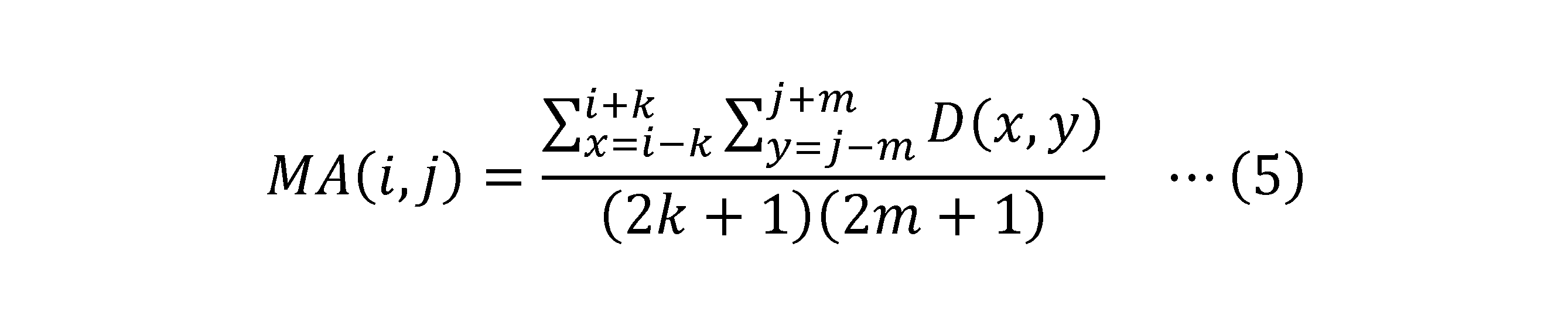
続いて座標導出部16は、交差位置(i,j)ごとに、次の式(6)に従って差分値D(i,j)から移動平均MA(i,j)を減算することにより、減算値DM(i,j)を算出する(ステップST32)。こうして算出された減算値DM(i,j)は、図19に示すように、概ね、差分値D(i,j)からワイド凸部分が除去されたものとなる。その後は、差分値D(i,j)の代わりに減算値DM(i,j)を用いる他は、図14に示した処理と同様の処理を行う(ステップST33以降)。

本変形例によれば、上記実施の形態と同様の効果が得られることに加え、減算値DM(i,j)からワイド凸部が概ね除去されて指示体凸部が強調されることから、図19に示すように複数の指示体凸部が存在している場合に、これらをより確実に検出することが可能になる。
また、上記実施の形態では、図13のステップST3で算出した差分値D(i,j)をそれ以降の処理でそのまま使用していたが、キャリブレーション処理によって基準値S(i,j)が大きくなっているところでは差分値D(i,j)が小さくなってしまうことから、差分値D(i,j)の底上げを行うこととしてもよい。以下、具体的に説明する。
図20は、図13に示したタッチ検出処理の変形例を示す図である。同図に示すように、この変形例では、ステップST3とステップST4の間に加算処理(ステップST40)を挿入している。また、最初に設定される値の一つとして、この加算処理で用いる加算値Bが追加される(ステップS0a)。
図21は、この加算処理の処理フローを示す図である。同図に示すように、この加算処理においてタッチ検出部15は、最新の基準値S(i,j)とステップST0aで設定された初期基準値S0(i,j)との比較を行い(ステップST42)、これらが一致しない場合に、ステップST3で算出した差分値D(i,j)に加算値Bを加算する(ステップST43)、という処理をすべての交差位置(i,j)について実施する(ステップST41)。なお、ステップST42の比較を行うために、初期基準値S0(i,j)は、上述した2つのフレームメモリFM0とは異なるフレームメモリに格納しておく必要がある。最新の基準値S(i,j)と初期基準値S0(i,j)とが一致しないということは、その交差位置(i,j)がキャリブレーションの対象となったということであるので、図21の処理によれば、キャリブレーションの対象となった交差位置(i,j)のみ、加算値Bの分だけ差分値D(i,j)の底上げを行うことが可能になる。
図22は、本変形例の効果を説明するための図である。図22(a)は、タッチ面5a内に背面支持によるワイド凸部の発生領域AAが存在している状態で、5本の指F1~F5がタッチ面5aに同時にタッチしたという状態を模式的に示したものである。また、図22(b)は、そのときにステップST3で算出される差分値D(i,j)を模式的に示し、図22(c)は、さらにステップST40を経た後の差分値D(i,j)を模式的に示している。なお、図22には、キャリブレーションが既に十分に実行され、差分値D(i,j)には背面支持によるワイド凸部が現れなくなっている状態を示している。
図22(b)に示すように、領域AAにタッチした指F3,F4に対応する指示体凸部は、領域AA以外にタッチした指F1,F2,F5に対応する指示体凸部に比べて小さなものとなる。これは、キャリブレーションが実行された結果、領域AAで基準値S(i,j)が大きくなっているためである。図21に示した加算処理を実施することにより、図22(c)に示すように、領域AA内で差分値D(i,j)が加算値Bの分だけ底上げされる。その結果、指F3,F4に対応する指示体凸部が、指F1,F2,F5に対応する指示体凸部と同程度のレベルにまで底上げされている。このように、本変形例によれば、キャリブレーション処理によって基準値S(i,j)が大きくなってしまっているところでも、そうなっていないところと同様に、高い指示体凸部を得ることが可能になる。
また、上記実施の形態では、図13のステップST3で算出した差分値D(i,j)の中にタッチ検出閾値T2を超えるものがない場合(ステップST4の否定判定)、図14のステップST13で算出した面積SQがパーム判定値SQ0を下回っている場合(ステップST15の否定判定)、図14のステップST13で算出した重心GCurが直前のループで算出した重心GCurと同じでない場合(ステップST18の否定判定)、及び、変数countが較正タイマーCount0を下回っている場合(ステップST21の否定判定)には、キャリブレーションを行わないこととしたが、これらの場合にもキャリブレーションを行うこととしてもよい。以下、具体的に説明する。
図23は、図13に示したタッチ検出処理の他の変形例を示す図である。同図に示すように、この変形例では、ステップST5の後段にもキャリブレーション処理(ステップST50)を挿入している。また、最初に設定される値の一つとして、このキャリブレーション処理で用いる較正係数aが追加される(ステップS0b)。
ステップST50のキャリブレーション処理では、次の式(7)により、図2に示したフレームメモリFM0に記憶される基準値S(i,j)が更新される。この場合において、較正係数aは、ステップST8で用いる較正係数Aに比べて小さな値とすることが好適である。こうすることで、ステップST8でのキャリブレーションでは、ステップST50でのキャリブレーションに比べ、基準値S(i,j)が速く差分値D(i,j)に近づくことになる。つまり、背面支持によるワイド凸部を検出した場合に、そうでない場合に比べて迅速に、ワイド凸部をキャンセルすることが可能になる。

図24は、図14に示した座標導出処理の他の変形例を示す図である。同図に示すように、この変形例では、ステップST11とステップST12の間に、タッチ検出閾値T1が変数T1last以上であるか否かを判定する処理(ステップST60)と、ステップST60で否定的な判定結果が得られた場合に、タッチ検出閾値T1を再設定する処理(ステップST61)とを挿入している。また、座標導出処理の最終段に、変数T1lastにタッチ検出閾値T1を設定する処理を挿入している(ステップST62)。
ステップST61におけるタッチ検出閾値T1の再設定は、ステップST11で設定した値よりも大きな値をタッチ検出閾値T1に再設定するための処理であり、具体的には次の式(8)に示すように、タッチ検出閾値T1のE倍に変数T1lastの(1-E)倍を加算してなる値をタッチ検出閾値T1に再設定することによって実施される。ただし、Eは0<E<1を満たす定数(更新係数)であり、図13に示したステップST0において他の値とともに初期設定される。ステップST61が実行される場面では、ステップST11で算出されたタッチ検出閾値T1は変数T1lastよりも必ず小さいので、式(8)により算出されたタッチ検出閾値T1は、ステップST11で設定した値よりも必ず大きな値となる。

図25は、本変形例の効果を説明するための図である。同図(a)(c)(e)(g)は、指8によりタッチ面5aが押下された後、タッチ面5aのたわみが徐々に解消されていく様子を描いた断面図であり、(a)は、指8によりタッチ面5aが押下されている状態、(c)は、指8がタッチ面5aを離れた後も、タッチ面5aのたわみが継続している状態、(e)は、たわみが解消されつつ、なおも継続している状態、(g)はたわみが完全に解消された状態をそれぞれ示している。また、図25(b)(d)(f)(h)は、それぞれ同図(a)(c)(e)(g)に対応する差分値D(i,j)の状態を示すもので、各図に図示したタッチ検出閾値T1は、図24のステップST11により算出されたもの(ステップST61による再設定の前のもの)を示している。
図25に示すように、指8がタッチ面5aを押下したことによって生ずる「たわみ」はヒステリシスを有しており、指8がタッチ面5aから離れた後もすぐには解消せず、徐々に解消していく。その際、タッチ検出閾値T1は徐々に小さくなっていき、図25(c)に示すようにタッチ検出閾値T1がタッチ検出閾値T2を下回ったところでステップST12の判定結果が否定となり、検出座標をホストCPUに出力する処理(ステップST14)が実行されなくなる。
逆に言えば、タッチ検出閾値T1がタッチ検出閾値T2を下回るまでの間、指示体凸部が存在しないにもかかわらず、検出座標がホストCPUに出力され続ける。こうして出力される検出座標は、図25(d)に斜線で示した領域、すなわち「たわみ」によるワイド凸部の上端部分の重心に過ぎず、指示体の位置を示すものではないので、ホストCPUから見ると誤検出の結果ということになる。
本変形例では、ステップST60,ST61,ST62の処理を追加したことにより、図25に例示したようにタッチ検出閾値T1が低下していく場面で、タッチ検出閾値T1の低下が遅れることになる。その結果、図25(d)のような場面において、タッチ検出閾値T1が最大値D(imax,jmax)を上回り、ステップST13で「D(i,j)>T1を満たす領域」が検出されなくなるので、上記のように、ワイド凸部の上端部分の重心に過ぎない検出座標がホストCPUに出力されてしまうことを防止できる。したがって、本変形例によれば、「たわみ」のヒステリシスによって生ずる指示体の位置の誤検出が防止されることになる。
なお、定数Eの具体的な値は、上記効果が得られるよう実験的に決定されることが好ましいが、例えば0.1や0.5などの値とすることが好ましい。
その他にも、本実施の形態によるタッチ検出装置1には、種々の変形例が考えられる。例えば、上記実施の形態では、新たに算出した重心GCurと直前の重心GCurとが完全に一致しているか否かを判定し(図14のステップS18)、その結果が一致となる状態が較正タイマーCount0によって示される時間だけ継続している場合にキャリブレーション処理が起動されるようにしたが、この処理は一例であり、重心GCurが所定時間内に所定範囲を超えて移動していない場合に、キャリブレーション処理が起動されるようにすればよい。具体的な例を挙げると、例えば、新たに算出した重心GCurが直前の重心GCurを中心とする所定範囲内に含まれることを判定することとしてもよい。この場合の所定範囲としては、例えば、タッチ面5a上の実寸で、直前の重心GCurを中心とする直径5mmの円内又は5mm四方の矩形内という範囲、より好適には、タッチ面5a上の実寸で、直前の重心GCurを中心とする直径1.5mmの円内又は1.5mm四方の矩形内という範囲を設定することが好ましい。
また、本発明はエアーギャップ型のタッチ検出装置について特に有効であるが、エアーギャップ型以外のタッチ検出装置にも適用可能である。したがって、事前にタッチセンサの実装環境がわからないような場合も含め、本発明は汎用的に利用することができる。
また、上記実施の形態は、最大値や検出値などが正の値をとるものとして説明したが、これらが負の値をとるものとして説明することも可能であり、そのような場合、値間の大小関係が上で説明したものとは逆になることは言うまでもない。最大値を検出するとは、指の近接による静電容量の変化を正で検出する場合の最大値であり、指の近接による静電容量の変化を検出される電流の減少分として負で表わすような場合には、最小値を検出することに対応することになる。
1 タッチ検出装置
2 筐体
3 表示装置
3a 表示装置3の表示面
4 スペーサ
5 カバーパネル
5a タッチ面
6 タッチセンサ
6a タッチセンサ6の下面
6x X電極
6y Y電極
7 エアーギャップ
8,F1~F5 指
8a 拳
8b 掌
10 タッチセンサコントローラ
11 発振器
12,13 マルチプレクサ
14 アナログデジタル変換器
15 タッチ検出部
16 座標導出部
20 記憶部
AA 背面支持によるワイド凸部の発生領域
FM0,FM1 フレームメモリ
2 筐体
3 表示装置
3a 表示装置3の表示面
4 スペーサ
5 カバーパネル
5a タッチ面
6 タッチセンサ
6a タッチセンサ6の下面
6x X電極
6y Y電極
7 エアーギャップ
8,F1~F5 指
8a 拳
8b 掌
10 タッチセンサコントローラ
11 発振器
12,13 マルチプレクサ
14 アナログデジタル変換器
15 タッチ検出部
16 座標導出部
20 記憶部
AA 背面支持によるワイド凸部の発生領域
FM0,FM1 フレームメモリ
Claims (22)
- 複数のセンサ電極を含む静電容量方式のタッチセンサのコントローラにより実行されるタッチ検出方法であって、
前記複数のセンサ電極の交差位置ごとに、指示体と前記タッチセンサ間の静電容量に対応する検出値を取得するステップと、
前記交差位置ごとの前記検出値の中の最大値を取得するステップと、
固定値であるか、又は、前記最大値が大きいほど小さくなる値である減算値を前記最大値から減じた値に第1の閾値を決定するステップと、
前記第1の閾値を基準として、前記交差位置ごとの検出値に基づいて前記指示体の位置を導出するステップと
を含むタッチ検出方法。 - 前記交差位置ごとの基準値を取得するステップと、
前記交差位置ごとに、前記静電容量を示す容量値を取得するステップとをさらに含み、
前記検出値は、対応する前記容量値から対応する前記基準値を減じてなる差分値である
請求項1に記載のタッチ検出方法。 - 前記交差位置ごとの基準値を取得するステップと、
前記交差位置ごとに、前記静電容量を示す容量値を取得するステップと、
前記交差位置ごとに、前記容量値から前記基準値を減ずることによって差分値を算出するステップと、
前記交差位置ごとに、前記差分値の移動平均を算出するステップとをさらに含み、
前記検出値は、対応する前記差分値から対応する前記移動平均を減じてなる値である
請求項1に記載のタッチ検出方法。 - 対応する検出値が前記第1の閾値を超える交差位置により示される領域の代表位置を算出するステップと、
前記代表位置が所定時間内に所定範囲を超えて移動していない場合に、前記検出値に近づく方向に前記基準値を較正するキャリブレーションを起動するステップと
をさらに含む請求項2又は3に記載のタッチ検出方法。 - 前記面積を算出するステップは、前記領域の面積も算出し、
前記キャリブレーションを起動するステップは、前記面積が予め設定される第3の閾値を超える場合に、前記キャリブレーションを起動する
請求項4に記載のタッチ検出方法。 - 前記最大値を取得するステップは、前記検出値を取得するステップで取得された複数の検出値の中に、予め設定される第2の閾値を超えるものがある場合に実行される
請求項1乃至5のいずれか一項に記載のタッチ検出方法。 - 前記第1の閾値が低下している場合に、前記第1の閾値を決定するステップで決定された値よりも大きな値を前記第1の閾値に再設定するステップをさらに備え、
前記指示体の位置を導出するステップは、再設定された前記第1の閾値を基準として、前記交差位置ごとの検出値に基づいて前記指示体の位置を導出するよう構成される
請求項1乃至6のいずれか一項に記載のタッチ検出方法。 - 複数のセンサ電極を含む静電容量方式のタッチセンサのコントローラにより実行されるタッチ検出方法であって、
前記複数のセンサ電極の交差位置ごとの基準値を取得するステップと、
前記交差位置ごとに、前記静電容量を示す容量値を取得するステップと、
前記交差位置ごとに、前記容量値及び前記基準値に基づいて、指示体と前記タッチセンサ間の静電容量に対応する検出値を取得するステップと、
対応する検出値が第1の閾値を超える交差位置により示される領域の代表位置を算出するステップと、
前記代表位置の移動の有無を判定するステップと、
前記移動の有無を判定するステップの判定結果に応じて、前記検出値に近づく方向に前記基準値を較正するキャリブレーションを起動するステップと
を含むタッチ検出方法。 - 前記移動の有無を判定するステップは、前記代表位置が所定時間内に所定範囲を超えて移動しているか否かを判定し、その判定結果に応じて前記代表位置の移動の有無を判定するよう構成される
請求項8に記載のタッチ検出方法。 - 前記代表位置を算出するステップは、さらに前記領域の面積を算出し、
前記第1のキャリブレーションを起動するステップは、前記面積が予め設定される第3の閾値を超える場合であって前記移動の有無を判定するステップにより前記代表位置が移動していないと判定された場合に、前記キャリブレーションを起動する
請求項8又は9に記載のタッチ検出方法。 - 前記キャリブレーションを起動するステップは、前記移動の有無を判定するステップにより前記代表位置が移動していないと判定された場合に、前記移動の有無を判定するステップにより前記代表位置が移動していると判定された場合に比して速く前記基準値が前記検出値に近づくように前記キャリブレーションを実行する
請求項8乃至10のいずれか一項に記載のタッチ検出方法。 - 前記キャリブレーションを起動するステップは、前記移動の有無を判定するステップにより前記代表位置が移動していると判定された場合には前記キャリブレーションを行わない
請求項11に記載のタッチ検出方法。 - 前記代表位置は、前記領域の重心である
請求項8乃至12のいずれか一項に記載のタッチ検出方法。 - 前記代表位置をホストCPUに対して出力するステップ
をさらに含む請求項8乃至13のいずれか一項に記載のタッチ検出方法。 - 前記交差位置ごとの検出値の中の最大値を取得するステップと、
固定値であるか、又は、前記最大値が大きいほど小さくなる値である減算値を前記最大値から減ずることにより、第1の閾値を算出するステップとをさらに含み、
前記代表位置を算出するステップは、前記第1の閾値が予め設定される第2の閾値以上である場合に起動される
請求項8乃至14のいずれか一項に記載のタッチ検出方法。 - 前記検出値は、対応する前記容量値から対応する前記基準値を減じてなる差分値である
請求項8乃至15のいずれか一項に記載のタッチ検出方法。 - 前記交差位置ごとに、前記容量値から前記基準値を減ずることによって差分値を算出するステップと、
前記交差位置ごとに、前記差分値の移動平均を算出するステップとをさらに含み、
前記検出値は、対応する前記差分値から対応する前記移動平均を減じてなる値である
請求項8乃至15のいずれか一項に記載のタッチ検出方法。 - 前記キャリブレーションにより前記基準値が較正された前記交差位置について、前記検出値に所定値を加算するステップ
をさらに含む請求項8乃至17のいずれか一項に記載のタッチ検出方法。 - 静電容量方式のタッチセンサを構成する複数のセンサ電極と、
前記複数のセンサ電極の交差位置ごとに、指示体と前記タッチセンサ間の静電容量を示す容量値を取得するタッチ検出部と、
前記交差位置ごとの前記容量値に基づく値である検出値の中の最大値を取得し、固定値であるか、又は、前記最大値が大きいほど小さくなる値である減算値を前記最大値から減じた値に第1の閾値を決定し、決定した前記第1の閾値を基準として、前記交差位置ごとの検出値に基づいて前記指示体の位置を導出する座標導出部と
を含むタッチ検出装置。 - 静電容量方式のタッチセンサを構成する複数のセンサ電極と、
前記複数のセンサ電極の交差位置ごとの基準値を取得するとともに、前記交差位置ごとに前記静電容量を示す容量値を取得し、さらに、前記交差位置ごとに、対応する前記容量値から対応する前記基準値を減じてなる差分値を算出するタッチ検出部と、
前記差分値又は前記差分値に基づいて取得される検出値が第1の閾値を超える交差位置により示される領域の代表位置を算出するとともに該代表位置の移動の有無を判定し、その判定結果に応じて、前記検出値に近づく方向に前記基準値を較正するキャリブレーションを起動する座標導出部と
を含むタッチ検出装置。 - 静電容量方式のタッチセンサを構成する複数のセンサ電極とともに用いられるタッチセンサコントローラであって、
前記複数のセンサ電極の交差位置ごとに、指示体と前記タッチセンサ間の静電容量を示す容量値を取得するタッチ検出部と、
前記交差位置ごとの前記容量値に基づく値である検出値の中の最大値を取得し、固定値であるか、又は、前記最大値が大きいほど小さくなる値である減算値を前記最大値から減じた値に第1の閾値を決定し、決定した前記第1の閾値を基準として、前記交差位置ごとの検出値に基づいて前記指示体の位置を導出する座標導出部と
を含むタッチセンサコントローラ。 - 静電容量方式のタッチセンサを構成する複数のセンサ電極とともに用いられるタッチセンサコントローラであって、
前記複数のセンサ電極の交差位置ごとの基準値を取得するとともに、前記交差位置ごとに前記静電容量を示す容量値を取得し、さらに、前記交差位置ごとに、対応する前記容量値から対応する前記基準値を減じてなる差分値を算出するタッチ検出部と、
前記差分値又は前記差分値に基づいて取得される検出値が第1の閾値を超える交差位置により示される領域の代表位置を算出するとともに該代表位置の移動の有無を判定し、その判定結果に応じて、前記検出値に近づく方向に前記基準値を較正するキャリブレーションを起動する座標導出部と
を含むタッチセンサコントローラ。
Priority Applications (5)
| Application Number | Priority Date | Filing Date | Title |
|---|---|---|---|
| JP2015561817A JP5901870B1 (ja) | 2015-09-15 | 2015-09-15 | タッチ検出方法、タッチ検出装置、及びタッチセンサコントローラ |
| PCT/JP2015/076095 WO2017046865A1 (ja) | 2015-09-15 | 2015-09-15 | タッチ検出方法、タッチ検出装置、及びタッチセンサコントローラ |
| TW105125945A TWI712927B (zh) | 2015-09-15 | 2016-08-15 | 觸碰檢測方法、觸碰檢測裝置及觸碰感測器控制器 |
| US15/901,559 US10990224B2 (en) | 2015-09-15 | 2018-02-21 | Touch detection method, touch detection apparatus, and touch sensor controller |
| US17/216,335 US11243639B2 (en) | 2015-09-15 | 2021-03-29 | Touch detection method, touch detection apparatus, and touch sensor controller |
Applications Claiming Priority (1)
| Application Number | Priority Date | Filing Date | Title |
|---|---|---|---|
| PCT/JP2015/076095 WO2017046865A1 (ja) | 2015-09-15 | 2015-09-15 | タッチ検出方法、タッチ検出装置、及びタッチセンサコントローラ |
Related Child Applications (1)
| Application Number | Title | Priority Date | Filing Date |
|---|---|---|---|
| US15/901,559 Continuation US10990224B2 (en) | 2015-09-15 | 2018-02-21 | Touch detection method, touch detection apparatus, and touch sensor controller |
Publications (1)
| Publication Number | Publication Date |
|---|---|
| WO2017046865A1 true WO2017046865A1 (ja) | 2017-03-23 |
Family
ID=55747716
Family Applications (1)
| Application Number | Title | Priority Date | Filing Date |
|---|---|---|---|
| PCT/JP2015/076095 Ceased WO2017046865A1 (ja) | 2015-09-15 | 2015-09-15 | タッチ検出方法、タッチ検出装置、及びタッチセンサコントローラ |
Country Status (4)
| Country | Link |
|---|---|
| US (2) | US10990224B2 (ja) |
| JP (1) | JP5901870B1 (ja) |
| TW (1) | TWI712927B (ja) |
| WO (1) | WO2017046865A1 (ja) |
Cited By (3)
| Publication number | Priority date | Publication date | Assignee | Title |
|---|---|---|---|---|
| JP2020060930A (ja) * | 2018-10-10 | 2020-04-16 | アルパイン株式会社 | 入力装置 |
| JPWO2021070313A1 (ja) * | 2019-10-10 | 2021-04-15 | ||
| US12242688B2 (en) | 2023-02-16 | 2025-03-04 | Wacom Co., Ltd. | Electronic device, integrated circuit, and input system |
Families Citing this family (3)
| Publication number | Priority date | Publication date | Assignee | Title |
|---|---|---|---|---|
| CN111488083B (zh) * | 2019-01-25 | 2023-03-31 | 瑞昱半导体股份有限公司 | 具有自校准功能的电容式触摸检测装置 |
| US10905946B2 (en) * | 2019-02-28 | 2021-02-02 | Valve Corporation | Continuous controller calibration |
| JP2025150570A (ja) * | 2024-03-27 | 2025-10-09 | アルプスアルパイン株式会社 | 静電入力装置 |
Citations (6)
| Publication number | Priority date | Publication date | Assignee | Title |
|---|---|---|---|---|
| JP2011210038A (ja) * | 2010-03-30 | 2011-10-20 | Renesas Sp Drivers Inc | タッチ判別装置及びデータ処理システム |
| JP2012150747A (ja) * | 2011-01-21 | 2012-08-09 | Mitsubishi Electric Corp | タッチパネル装置 |
| JP2013088982A (ja) * | 2011-10-17 | 2013-05-13 | Rohm Co Ltd | タッチ式入力装置およびそのコントローラ、制御方法、電子機器 |
| JP2013254331A (ja) * | 2012-06-06 | 2013-12-19 | Panasonic Corp | 入力装置、入力支援方法及びプログラム |
| JP2014056460A (ja) * | 2012-09-13 | 2014-03-27 | Tokai Rika Co Ltd | 入力装置 |
| JP2014203205A (ja) * | 2013-04-03 | 2014-10-27 | アルプス電気株式会社 | 静電容量検出装置 |
Family Cites Families (9)
| Publication number | Priority date | Publication date | Assignee | Title |
|---|---|---|---|---|
| US9019209B2 (en) * | 2005-06-08 | 2015-04-28 | 3M Innovative Properties Company | Touch location determination involving multiple touch location processes |
| US8074059B2 (en) * | 2005-09-02 | 2011-12-06 | Binl ATE, LLC | System and method for performing deterministic processing |
| US8319749B2 (en) * | 2007-02-23 | 2012-11-27 | Sony Corporation | Image pickup apparatus, display-and-image-pickup apparatus and image pickup processing apparatus |
| US20090256825A1 (en) * | 2008-04-11 | 2009-10-15 | Gunnar Klinghult | Pen stylus enabled capacitive touch system and method |
| JP5423297B2 (ja) | 2009-09-30 | 2014-02-19 | 富士通株式会社 | 入力装置、入力処理プログラム、および入力制御方法 |
| US20120206399A1 (en) * | 2011-02-10 | 2012-08-16 | Alcor Micro, Corp. | Method and System for Processing Signals of Touch Panel |
| KR20130070893A (ko) * | 2011-12-20 | 2013-06-28 | 삼성디스플레이 주식회사 | 터치 감지 시스템 및 그의 구동방법 |
| JP6006591B2 (ja) | 2012-09-13 | 2016-10-12 | キヤノン株式会社 | 電子機器 |
| TW201413521A (zh) * | 2012-09-28 | 2014-04-01 | Novatek Microelectronics Corp | 觸控面板的觸控偵測方法 |
-
2015
- 2015-09-15 JP JP2015561817A patent/JP5901870B1/ja active Active
- 2015-09-15 WO PCT/JP2015/076095 patent/WO2017046865A1/ja not_active Ceased
-
2016
- 2016-08-15 TW TW105125945A patent/TWI712927B/zh active
-
2018
- 2018-02-21 US US15/901,559 patent/US10990224B2/en active Active
-
2021
- 2021-03-29 US US17/216,335 patent/US11243639B2/en active Active
Patent Citations (6)
| Publication number | Priority date | Publication date | Assignee | Title |
|---|---|---|---|---|
| JP2011210038A (ja) * | 2010-03-30 | 2011-10-20 | Renesas Sp Drivers Inc | タッチ判別装置及びデータ処理システム |
| JP2012150747A (ja) * | 2011-01-21 | 2012-08-09 | Mitsubishi Electric Corp | タッチパネル装置 |
| JP2013088982A (ja) * | 2011-10-17 | 2013-05-13 | Rohm Co Ltd | タッチ式入力装置およびそのコントローラ、制御方法、電子機器 |
| JP2013254331A (ja) * | 2012-06-06 | 2013-12-19 | Panasonic Corp | 入力装置、入力支援方法及びプログラム |
| JP2014056460A (ja) * | 2012-09-13 | 2014-03-27 | Tokai Rika Co Ltd | 入力装置 |
| JP2014203205A (ja) * | 2013-04-03 | 2014-10-27 | アルプス電気株式会社 | 静電容量検出装置 |
Cited By (6)
| Publication number | Priority date | Publication date | Assignee | Title |
|---|---|---|---|---|
| JP2020060930A (ja) * | 2018-10-10 | 2020-04-16 | アルパイン株式会社 | 入力装置 |
| JP7094631B2 (ja) | 2018-10-10 | 2022-07-04 | アルパイン株式会社 | 入力装置 |
| JPWO2021070313A1 (ja) * | 2019-10-10 | 2021-04-15 | ||
| WO2021070313A1 (ja) * | 2019-10-10 | 2021-04-15 | 株式会社ワコム | タッチ検出方法及びタッチ検出装置 |
| JP7357999B2 (ja) | 2019-10-10 | 2023-10-10 | 株式会社ワコム | タッチ検出方法及びタッチ検出装置 |
| US12242688B2 (en) | 2023-02-16 | 2025-03-04 | Wacom Co., Ltd. | Electronic device, integrated circuit, and input system |
Also Published As
| Publication number | Publication date |
|---|---|
| JP5901870B1 (ja) | 2016-04-13 |
| US10990224B2 (en) | 2021-04-27 |
| US20180181255A1 (en) | 2018-06-28 |
| US11243639B2 (en) | 2022-02-08 |
| TWI712927B (zh) | 2020-12-11 |
| TW201721383A (zh) | 2017-06-16 |
| JPWO2017046865A1 (ja) | 2017-09-14 |
| US20210216189A1 (en) | 2021-07-15 |
Similar Documents
| Publication | Publication Date | Title |
|---|---|---|
| JP5901870B1 (ja) | タッチ検出方法、タッチ検出装置、及びタッチセンサコントローラ | |
| JP5989220B1 (ja) | タッチ検出方法、タッチ検出装置、及びタッチセンサコントローラ | |
| JP6710345B2 (ja) | タッチパネル装置 | |
| JP5656307B1 (ja) | 電子機器 | |
| EP2724215B1 (en) | Touch sensor system | |
| CN107506131B (zh) | 信息处理设备、信息处理设备的输入控制方法及记录介质 | |
| TWI546711B (zh) | 用於決定有角度之接觸幾何形狀的方法及計算裝置 | |
| JP5904440B2 (ja) | 操作入力装置、操作入力方法およびプログラム | |
| CN109313492A (zh) | 人机接口系统 | |
| JP6308769B2 (ja) | 情報処理装置、その制御方法、プログラム、及び記憶媒体 | |
| CN102841702A (zh) | 信息处理装置、显示控制方法以及程序 | |
| JP6554013B2 (ja) | 入力装置、入力装置の制御方法、入力装置を備える電子機器、電子機器の制御方法、プログラムおよび記憶媒体 | |
| CN111049953A (zh) | 一种折叠屏终端的控制方法、装置及电子设备 | |
| JP2017076222A5 (ja) | ||
| CN107544624B (zh) | 一种智能穿戴产品 | |
| JP2016006610A (ja) | 電子機器及び制御方法 | |
| CN104076970B (zh) | 信息处理设备和方法 | |
| CN106406578B (zh) | 信息处理装置、输入控制方法、信息处理装置的控制方法 | |
| JP6112506B2 (ja) | 携帯型電子機器 | |
| JP2017157079A (ja) | 情報処理装置、表示制御方法、及び表示制御プログラム | |
| JP2015087933A (ja) | 情報処理装置およびプログラム | |
| JP6508652B2 (ja) | 情報端末装置 | |
| KR101673135B1 (ko) | 디지타이저 시스템 | |
| CN109542261B (zh) | 物体追踪方法以及物体追踪系统 | |
| CN103502918B (zh) | 以力检测扩增的用户接口元件 |
Legal Events
| Date | Code | Title | Description |
|---|---|---|---|
| ENP | Entry into the national phase |
Ref document number: 2015561817 Country of ref document: JP Kind code of ref document: A |
|
| 121 | Ep: the epo has been informed by wipo that ep was designated in this application |
Ref document number: 15904054 Country of ref document: EP Kind code of ref document: A1 |
|
| NENP | Non-entry into the national phase |
Ref country code: DE |
|
| 122 | Ep: pct application non-entry in european phase |
Ref document number: 15904054 Country of ref document: EP Kind code of ref document: A1 |