WO2017043440A1 - 体外循環訓練システム - Google Patents
体外循環訓練システム Download PDFInfo
- Publication number
- WO2017043440A1 WO2017043440A1 PCT/JP2016/075977 JP2016075977W WO2017043440A1 WO 2017043440 A1 WO2017043440 A1 WO 2017043440A1 JP 2016075977 W JP2016075977 W JP 2016075977W WO 2017043440 A1 WO2017043440 A1 WO 2017043440A1
- Authority
- WO
- WIPO (PCT)
- Prior art keywords
- blood
- instruction
- simulated
- pressure sensor
- stenosis
- Prior art date
- Legal status (The legal status is an assumption and is not a legal conclusion. Google has not performed a legal analysis and makes no representation as to the accuracy of the status listed.)
- Ceased
Links
Images




Classifications
-
- G—PHYSICS
- G09—EDUCATION; CRYPTOGRAPHY; DISPLAY; ADVERTISING; SEALS
- G09B—EDUCATIONAL OR DEMONSTRATION APPLIANCES; APPLIANCES FOR TEACHING, OR COMMUNICATING WITH, THE BLIND, DEAF OR MUTE; MODELS; PLANETARIA; GLOBES; MAPS; DIAGRAMS
- G09B9/00—Simulators for teaching or training purposes
Definitions
- the present invention relates to an extracorporeal circulation training system used for extracorporeal circulation training.
- an extracorporeal circulation device is very important in open heart surgery treatment for severe heart disease.
- Extracorporeal circulation devices are operated by clinical engineers. Therefore, high-level skills are required for clinical engineers and the like.
- the importance of extracorporeal circulation technology education for clinical engineers and the like has increased.
- a training apparatus has been proposed in which a plurality of on-off valves are arranged in a blood removal circuit or a blood transmission circuit, and the trouble due to a malfunction in the human body or the blood removal / blood transmission circuit is reproduced by opening and closing them (for example, Patent Documents). 1).
- the training device of Patent Document 1 reproduces troubles caused by troubles in the human body and blood removal / blood transmission circuit, but does not reproduce troubles caused by troubles such as an artificial lung constituting the extracorporeal circulation device. .
- Troubles that occur when using the extracorporeal circulation device are caused not only by a malfunction in the human body and blood removal / blood transmission circuit, but also by a malfunction in a device such as an artificial lung constituting the extracorporeal circulation apparatus. Under such circumstances, there is a need for a training device / system that can reproduce a trouble caused by a malfunction in a device such as an artificial lung constituting an extracorporeal circulation device.
- an object of the present invention is to provide an extracorporeal circulation training system capable of reproducing a trouble caused by a malfunction of an apparatus constituting the extracorporeal circulation apparatus.
- the present invention relates to a simulated circulator that simulates the hemodynamics of a living body, and an extracorporeal circulator connected to the simulated circulator so as to allow blood removal and blood delivery, and remove the simulated blood from the simulated circulator.
- a blood removal circuit that bleeds blood
- a blood delivery circuit that returns simulated blood from the blood removal circuit to a simulated circulation device
- an artificial lung disposed on the blood delivery circuit, the blood delivery circuit, and the blood removal circuit
- An extracorporeal circulation apparatus comprising: a blood pump for connecting the simulated blood from the blood removal circuit to the blood circulation circuit to return the simulated blood to the simulated circulation apparatus through the artificial lung; and
- a first stenosis device disposed at a first position closer to the blood pump than the oxygenator on the blood circuit and constricting the first position in the blood circuit according to a first instruction;
- the simulated circulatory device rather than the artificial lung
- a second stenosis device disposed in a second position on the side and
- An extracorporeal circulation training system comprising: a flow sensor that detects a flow rate of simulated blood; and a notification unit that notifies detection results of the first pressure sensor, the second pressure sensor, and the flow sensor. That.
- the extracorporeal circulation training system is arranged at a third position in the blood removal circuit, and a third constriction device that constricts the third position in the blood removal circuit according to a third instruction; and the second blood circulation circuit in the second blood supply circuit.
- a fourth stenosis device which is disposed at a fourth position on the simulated circulation device side from the pressure sensor position and constricts the fourth position in the blood supply circuit according to a fourth instruction; the third position in the blood removal circuit;
- a third pressure sensor for detecting the pressure of the simulated blood at a third pressure sensor position between the blood pump and the stenosis instructing unit in the third stenosis device and / or the fourth stenosis device.
- the third instruction and / or the fourth instruction can be further output, and the notification unit further notifies the detection result of the third pressure sensor.
- the extracorporeal circulation training system includes an instruction input unit capable of inputting the first instruction, the second instruction, the third instruction, and the fourth instruction, and an administrator terminal having the stenosis instruction unit, and the simulated circulation It is preferable to further include a trainee terminal having a display unit that displays a part of information output from the device or the manager terminal.
- the extracorporeal circulation training system can troubleshoot the extracorporeal circulation device based on the detection results of the first pressure sensor, the second pressure sensor, the third pressure sensor, and the flow rate sensor notified by the notification unit. It is preferable to be configured to be recognizable.
- the present invention also relates to a simulated circulation device that simulates hemodynamics of a living body, and an extracorporeal circulation device that is connected to the simulated circulation device so that blood can be removed and blood can be fed from the simulated circulation device.
- a blood removal circuit for blood removal, a blood delivery circuit for returning the simulated blood from the blood removal circuit to a simulated circulation device, and a blood collection device disposed on the blood removal circuit and removed from the simulated circulation device A blood reservoir, an artificial lung disposed on the blood feeding circuit, an arterial filter disposed on the simulated circulation device side of the artificial lung on the blood feeding circuit, the blood removal circuit, and the blood feeding
- a blood pump for connecting the circuit and returning the simulated blood to the simulated circulation device through the artificial lung and the arterial filter by feeding the simulated blood from the blood removal circuit to the blood feeding circuit
- Extracorporeal circulation device and front A first stenosis device disposed at a first position closer to the blood pump than the oxygenator on the blood supply circuit and constricting the first position in the
- the extracorporeal circulation training system is arranged at a fifth position closer to the simulated circulation device than the blood storage part in the blood removal circuit, and a fifth constriction device narrows the fifth position in the blood removal circuit according to a fifth instruction.
- a sixth stenosis device disposed at a sixth position closer to the simulated circulation device than the arterial filter in the blood supply circuit, and stenosis of the sixth position in the blood supply circuit according to a sixth instruction;
- a seventh stenosis device disposed at a seventh position closer to the simulated circulation device than the sixth position in the circuit and constricting the seventh position in the blood supply circuit according to a seventh instruction; and the blood reservoir in the blood supply circuit
- a fifth pressure sensor for detecting the pressure of the simulated blood at a fifth pressure sensor position between the blood pump and the arterial filter and the seventh position in the blood feeding circuit.
- a sixth pressure sensor for detecting the pressure of the simulated blood at the sixth pressure sensor position, wherein the stenosis instruction unit is any one of the fifth stenosis device, the sixth stenosis device, and the seventh stenosis device.
- the notification unit displays the detection results of the fifth pressure sensor and the sixth pressure sensor. Further notification is preferable.
- the extracorporeal circulation training system includes an instruction input unit capable of inputting the first instruction, the second instruction, the fifth instruction, the sixth instruction, and the seventh instruction, and an administrator terminal having the stenosis instruction unit; It is preferable to further comprise a trainee terminal having a display unit for displaying a part of information output from the simulated circulation device or the manager terminal.
- the extracorporeal circulation training system is based on the detection results of the first pressure sensor, the second pressure sensor, the fifth pressure sensor, the sixth pressure sensor, and the flow rate sensor that are notified by the notification unit. It is preferable to be configured so that troubles in the extracorporeal circulation apparatus can be recognized.
- an extracorporeal circulation training system capable of reproducing troubles caused by malfunctions of devices constituting the extracorporeal circulation device.
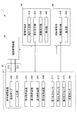
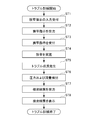
- 1 is an overall view showing a configuration of an extracorporeal circulation training system in a first embodiment. It is a block diagram which shows the structure of the extracorporeal circulation training system in 1st Embodiment. It is a flowchart explaining the effect
- the extracorporeal circulation training system 1 of the first embodiment includes a simulated circulation device 10, an extracorporeal circulation device 20, a first stenosis device 291, a second stenosis device 292, a third stenosis device 293, and a first stenosis device 293.
- 4 stenosis device 294, first pressure sensor 271, second pressure sensor 272 and third pressure sensor 273, flow sensor 280, manager terminal 30, and trainer terminal 40 are provided.
- the simulated circulation device 10 is configured to simulate the hemodynamics of a living body (human, animal, etc.).
- the simulated circulation device 10 is connected to the extracorporeal circulation device 20 by a blood removal circuit 210 and a blood transmission circuit 220 (described later) that constitute the extracorporeal circulation device 20.
- the simulated circulator 10 is connected to the extracorporeal circulator 20 through the blood removal circuit 210 and the blood delivery circuit 220 so as to circulate the simulated blood.
- the simulated blood refers to a liquid having various properties (for example, viscosity, temperature, etc.) similar to those of living blood.
- the simulated circulation device 10 includes a blood pressure sensor (not shown) and the like, and is configured to be able to output information such as blood pressure to the administrator terminal 30 and the trainee terminal 40.
- the extracorporeal circulation device 20 is connected to the simulated circulation device 10 so as to allow blood removal and blood supply.
- the extracorporeal circulation device 20 includes a blood removal circuit 210, a blood supply circuit 220, an oxygenator 250, a blood supply pump 240, and an oxygenator device 290 as a notification unit.
- the blood removal circuit 210 is a circuit that removes simulated blood from the simulated circulation device 10.
- the blood removal circuit 210 is connected to the blood delivery circuit 220 via the blood delivery pump 240.
- the blood removal circuit 210 includes a blood removal cannula and a plurality of circuit tubes.
- the plurality of circuit tubes are hollow tubes made of an elastic material.
- the plurality of circuit tubes are configured such that the hollow portion is narrowed by applying a force from the outside.
- the plurality of circuit tubes are tubes formed of an elastic material that is deformed by applying a force from the outside and has a narrow inner diameter of the hollow portion.
- a third stenosis device 293 (a 3a stenosis device 293a and a 3b stenosis device 293b) and a third pressure sensor 273 are arranged.
- the blood supply circuit 220 is a circuit that returns the simulated blood from the blood removal circuit 210 to the simulated circulation device 10.
- the blood supply circuit 220 is connected to the blood removal circuit 210 via the blood supply pump 240.
- the blood supply circuit 220 includes a blood supply cannula and a plurality of circuit tubes.
- the plurality of circuit tubes are hollow tubes made of an elastic material. In the present embodiment, the plurality of circuit tubes are configured such that the hollow portion is narrowed by applying a force from the outside.
- the plurality of circuit tubes are tubes formed of an elastic material that is deformed by applying a force from the outside and has a narrow inner diameter of the hollow portion.
- a flow sensor 280 is disposed on the blood sending circuit 220.
- the artificial lung 250 is disposed on the blood supply circuit 220.
- the artificial lung 250 has a blood gas exchange function for removing carbon dioxide and adding oxygen, a body temperature regulation function, and the like.
- the artificial lung 250 performs a gas exchange process or a temperature adjustment process on the simulated blood introduced from the blood pump 240 and sends the simulated blood to the simulated circulation apparatus 10 side.
- the blood sending pump 240 connects the blood removal circuit 210 and the blood delivery circuit 220, and sends the simulated blood introduced from the blood removal circuit 210 to the blood delivery circuit 220.
- the blood pump 240 returns the simulated blood to the simulated circulation device 10 through the artificial lung 250.
- the blood pump 240 is driven based on an instruction from the administrator terminal 30.
- Each of the first stenosis device 291 to the fourth stenosis device 294 is disposed at a position K1 to a position K4 on the blood removal circuit 210 or the blood transmission circuit 220, and is located on the blood removal circuit 210 or the blood transmission circuit 220.
- Each of K1 to K4 is constricted.
- Each of the first stenosis device 291 to the fourth stenosis device 294 narrows each of the positions K1 to K4 on the blood removal circuit 210 or the blood transmission circuit 220 in accordance with the first to fourth instructions from the administrator terminal 30. .
- the first stenosis device 291 to the fourth stenosis device 294 are constricted so that the inner diameter of the circuit tube becomes narrow in each of the positions K1 to K4.
- the pressure of the simulated blood at the upstream side and the downstream side of the position K1 to the position K4 in the blood removal circuit 210 and the blood transmission circuit 220 respectively.
- the flow rate changes.
- the first stenosis device 291 to the fourth stenosis device 294 are elements for generating a simulated trouble in the extracorporeal circulation training system 1.
- each of the first stenosis device 291 to the fourth stenosis device 294 will be described.
- the first stenosis device 291 is arranged at the first position K1 on the blood feeding pump 240 side of the artificial lung 250 on the blood feeding circuit 220.
- the first stenosis device 291 narrows the first position K1 in the blood transmission circuit 220 in accordance with a first instruction that is a stenosis instruction from the administrator terminal 30.
- the first stenosis device 291 receives a first instruction from the administrator terminal 30 when, for example, a trouble due to a malfunction of the blood pump 240 is simulated.
- the second stenosis device 292 is disposed at the second position K2 on the simulated circulation device 10 side of the artificial lung 250 on the blood transmission circuit 220.
- the second stenosis device 292 narrows the second position K2 in the blood transmission circuit 220 in accordance with a second instruction that is a stenosis instruction from the administrator terminal 30.
- the second stenosis device 292 receives a second instruction from the administrator terminal 30 when a trouble due to a malfunction of the oxygenator 250 is simulated.
- the third stenosis device 293 is disposed at the third position K3 in the blood removal circuit 210.
- the third stenosis device 293 includes a 3a stenosis device 293a and a 3b stenosis device 293b.
- the third stenosis device 293 narrows the third position K3 in the blood removal circuit 210 in accordance with a third instruction that is a stenosis instruction.
- the 3a constriction device 293a and the 3b constriction device 293b constrict each of the 3a position K3a and the 3b position K3b in the blood removal circuit 210.
- the third stenosis device 293 receives a third instruction from the administrator terminal 30 when a trouble due to a problem with the blood removal circuit 210 or the blood removal cannula is simulated.
- the fourth stenosis device 294 is disposed at the fourth position K4 on the simulated circulation device 10 side with respect to the second stenosis device 292 and the second pressure sensor position S2 to be described later in the blood transmission circuit 220.
- the fourth stenosis device 294 narrows the fourth position K4 in the blood transmission circuit 220 according to the fourth instruction which is a stenosis instruction from the administrator terminal 30.
- the fourth stenosis device 294 receives a fourth instruction from the administrator terminal 30 when a trouble due to a malfunction of the blood supply circuit 220 or the blood supply cannula is simulated.
- the first pressure sensor 271 to the third pressure sensor 273 are arranged at the first pressure sensor position S1 to the third pressure sensor position S3 on the blood removal circuit 210 or the blood transmission circuit 220, respectively.
- Each of the first pressure sensor 271 to the third pressure sensor 273 detects the pressure of the simulated blood at each of the first pressure sensor position S1 to the third pressure sensor position S3 on the blood removal circuit 210 or the blood sending circuit 220.
- the results detected by the first pressure sensor 271 to the third pressure sensor 273 are output to the heart-lung machine 290.
- each of the first pressure sensor 271 to the third pressure sensor 273 will be described.
- the first pressure sensor 271 detects the pressure of the simulated blood at the first pressure sensor position S1 between the first position K1 and the artificial lung 250 in the blood sending circuit 220.
- the second pressure sensor 272 detects the pressure of the simulated blood at the second pressure sensor position S2 between the second position K2 and the simulated circulation device 10 in the blood sending circuit 220.
- the second pressure sensor 272 detects the pressure of the simulated blood at the second pressure sensor position S2 between the second position K2 and the fourth position K4 in the blood sending circuit 220.
- the third pressure sensor 273 detects the pressure of the simulated blood at the third pressure sensor position S3 between the third position K3 and the blood pump 240 in the blood removal circuit 210.
- the flow sensor 280 detects the flow rate of the simulated blood at a flow sensor position SF between the blood pump 240 and the first position K1 in the blood transmission circuit 220.
- the heart-lung machine 290 controls the operation of the extracorporeal circulation device 20.
- the heart-lung machine 290 includes a display unit that displays the results detected by the first pressure sensor 271, the second pressure sensor 272, the third pressure sensor 273, and the flow rate sensor 280. That is, the heart-lung machine 290 functions as a notification unit of the present invention.
- the notifying unit is not limited to the heart-lung machine 290 as shown in FIG. 1, but the pressure detected by the first pressure sensor 271, the second pressure sensor 272, and the third pressure sensor 273, and the flow rate sensor 280.
- a display device capable of displaying the detected flow rate may be used.
- the administrator terminal 30 is a terminal device used by the administrator.
- the administrator terminal 30 is configured to be capable of outputting the first to fourth instructions for instructing the stenosis operation to the first stenosis device 291 to the fourth stenosis device 294, respectively.
- the configuration of the administrator terminal 30 will be described later.
- the trainee terminal 40 is a terminal used by the trainee.
- the trainer terminal 40 is configured to be able to display information such as blood pressure output from the simulated circulation device 10 via the administrator terminal 30.
- the configuration of the trainer terminal 40 will be described later.
- the simulated circulation device 10 is configured to receive a predetermined instruction from the administrator terminal 30 and to output detection results from a plurality of sensors arranged therein to the administrator terminal 30.
- the simulated circulator 10 is based on predetermined instructions from the administrator terminal 30, for example, venous compliance, peripheral vascular resistance, arterial pressure, central venous pressure, pulmonary artery pressure, circulating blood flow, heart rate, arrhythmia, cardiac output, etc. Hemodynamics, blood gas, hematocrit, body temperature, etc. can be changed.
- the simulated circulator 10 also includes hemodynamics such as venous compliance, peripheral vascular resistance, arterial pressure, central venous pressure, pulmonary artery pressure, circulating blood flow rate, heart rate, arrhythmia, cardiac output, and blood gas, hematocrit.
- hemodynamics such as venous compliance, peripheral vascular resistance, arterial pressure, central venous pressure, pulmonary artery pressure, circulating blood flow rate, heart rate, arrhythmia, cardiac output, and blood gas, hematocrit.
- information such as body temperature can be output to the trainee terminal 40.
- the administrator terminal 30 is configured to be able to output a predetermined instruction to the simulated circulation device 10 as described above.
- the administrator causes the administrator terminal 30 to output a predetermined instruction to the simulated circulation device 10 according to the designated patient condition.
- the administrator terminal 30 is configured to be able to output the first instruction to the fourth instruction instructing the stenosis operation to the first stenosis apparatus 291 to the fourth stenosis apparatus 294.
- the administrator terminal 30 includes an instruction input unit 310, a stenosis instruction unit 320, an information reception unit 330, and a display unit 340.
- the instruction input unit 310 is configured to be able to input a first instruction to a fourth instruction.
- the instruction input unit 310 includes a selection unit (not shown) that selects any one of the first stenosis device 291 to the fourth stenosis device 294, and a stenosis degree in the stenosis device selected by the selection unit. It includes a stenosis degree designating unit and an execution instruction unit (not shown) that instructs execution of a stenosis operation.
- the stenosis instruction unit 320 is configured to be capable of outputting the first instruction to the fourth instruction to the first stenosis device 291 to the fourth stenosis device 294, respectively. Specifically, the stenosis instruction unit 320 instructs the stenosis apparatus selected by the instruction input unit 310 to stenosis with the stenosis degree specified by the stenosis degree specification unit (first instruction to fourth instruction). Is output.
- the information receiving unit 330 receives the detection result detected in the simulated circulation device 10.
- the display unit 340 displays the content of the instruction output to the simulated circulation device 10.
- the trainer terminal 40 is configured to be able to display information such as blood pressure output from the administrator terminal 30 or the simulated circulation device 10. More specifically, the trainee terminal 40 includes a display unit 420, and various types of information (for example, venous compliance, peripheral vascular resistance, Arterial pressure, central venous pressure, pulmonary artery pressure, circulating blood flow rate, heart rate, arrhythmia, hemodynamics such as cardiac output, and information such as blood gas, hematocrit, body temperature).
- the trainer displays information indicating the state of the patient displayed on the trainer terminal 40, pressure information from the first pressure sensor 271 to the fourth pressure sensor 274 displayed on the heart-lung machine 290, and information from the flow sensor 280. The flow rate information is confirmed, and the malfunction of the elements constituting the extracorporeal circulation device 20 is recognized.
- trouble training is started at a predetermined timing during extracorporeal circulation training.
- Trouble training proceeds in the following procedure.
- the administrator inputs a stenosis instruction for any stenosis device to the administrator terminal 30.
- the administrator terminal 30 receives a stenosis instruction from the administrator via the instruction input unit 310.
- the administrator selects one of the first stenosis device 291 to the fourth stenosis device 294 in accordance with the location of the assumed failure. For example, the administrator selects a stenosis device that performs a stenosis operation based on the table shown in FIG.
- step ST2 the administrator terminal 30 (stenosis instruction unit 320) sends any one of the first instruction to the fourth instruction that is a stenosis instruction to any one of the first stenosis device 291 to the fourth stenosis device 294. Is output.
- any one of the first stenosis device 291 to the fourth stenosis device 294 accepts one of the first instruction to the fourth instruction which is a stenosis instruction.
- Step ST4 any of the first stenosis device 291 to the fourth stenosis device 294 that has received any of the first instruction to the fourth instruction stenosis any of the first position K1 to the fourth position K4. It works to let you.
- step ST5 a trouble that causes a malfunction of any component of the extracorporeal circulation device 20 is simulated.
- each of the first pressure sensor 271 to the third pressure sensor 273 detects the pressure of the simulated blood at each of the first pressure sensor position S1 to the third pressure sensor position S3.
- the flow sensor 280 detects the flow rate of the simulated blood at the flow sensor position SF.
- each of the first pressure sensor 271 to the third pressure sensor 273 outputs a detection result to the oxygenator 290.
- the flow sensor 280 outputs the detection result to the oxygenator 290.
- step ST8 the heart-lung machine 290 displays the detection results (pressure information) from the first pressure sensor 271 to the third pressure sensor 273 and the detection results (flow information) from the flow sensor 280.
- the trainee confirms various information indicating the patient's state displayed on the trainee terminal 40 (display unit 420), and the first pressure sensor 271 to the third pressure sensor displayed on the heart-lung machine 290.
- the trouble content (trouble location) is recognized.
- the trainer grasps changes in pressure and flow rate shown in the phenomenon column of FIG. 4 and recognizes the content of the trouble (trouble location).
- the trainee tends to decrease the pressure (first pressure) detected by the first pressure sensor 271 and the pressure (second pressure) detected by the second pressure sensor 272. Pressure) is decreasing, the pressure detected by the third pressure sensor 273 (third pressure) is increasing, and the flow rate detected by the flow sensor 280 is decreasing, the blood pump 240 Recognize that a problem has occurred due to a problem.
- the trainee tends to increase the pressure (first pressure) detected by the first pressure sensor 271, and tends to decrease the pressure (second pressure) detected by the second pressure sensor 272.
- the pressure (third pressure) detected by the pressure sensor 273 tends to increase and the flow rate detected by the flow sensor 280 tends to decrease, it is recognized that a trouble due to a malfunction of the artificial lung 250 has occurred.
- the trainee is in a state where the pressure (first pressure) detected by the first pressure sensor 271 is decreasing, the pressure (second pressure) detected by the second pressure sensor 272 is decreasing, and the third pressure sensor
- the pressure detected by the H.273 third pressure
- the flow rate detected by the flow sensor 280 tends to decrease, trouble has occurred due to a problem with the blood removal circuit 210 or a problem with the blood removal cannula. Recognize
- the trainee tends to increase the pressure (first pressure) detected by the first pressure sensor 271, and the pressure detected by the second pressure sensor 272 (second pressure) tends to increase.
- the pressure (third pressure) detected by the pressure sensor 273 tends to increase and the flow rate detected by the flow sensor 280 tends to decrease, troubles due to the malfunction of the blood supply circuit 220 or the blood supply cannula may occur. Recognize that it occurred. Then, the trouble training ends.
- the extracorporeal circulation training system can cause a trouble caused by a failure of an element constituting the extracorporeal circulation apparatus to be simulated.
- the extracorporeal circulation training system which can reproduce the trouble by the malfunction of the apparatus which comprises an extracorporeal circulation apparatus can be provided.
- the extracorporeal circulation training system can be used for training for troubles caused by defects on the extracorporeal circulation apparatus side, not on the living body side.
- the extracorporeal circulation training system 1A in the second embodiment includes a simulated circulation device 10, an extracorporeal circulation device 20A, a first stenosis device 291, a second stenosis device 292, a fifth stenosis device 295, and a sixth.
- the extracorporeal circulation device 20A is connected to the simulated circulation device 10 so that blood can be removed and blood can be delivered.
- the extracorporeal circulation device 20A includes a blood removal circuit 210, a blood supply circuit 220, an artificial lung 250, a blood supply pump 240, a blood storage unit 230, and an arterial filter 260.
- the configuration of the blood removal circuit 210 is as described above. On the blood removal circuit 210, a blood reservoir 230, a fifth stenosis device 295 (5a stenosis device 295a and 5b stenosis device 295b), and a fifth pressure sensor 275 are arranged.
- the configuration of the blood sending circuit 220 is as described above.
- the oxygenator 250, the arterial filter 260, the first stenosis device 291, the second stenosis device 292, the sixth stenosis device 296, the seventh stenosis device 297, and the first pressure sensor are provided.
- 271, a second pressure sensor 272, a sixth pressure sensor 276, and a flow rate sensor 280 are arranged.
- the blood reservoir 230 is disposed on the blood removal circuit 210.
- the blood storage unit 230 is a part that stores the simulated blood removed from the simulated circulation apparatus 10.
- the arterial filter 260 is a filter disposed closer to the simulated circulation device 10 than the artificial lung 250 on the blood supply circuit 220.
- the blood pump 240 returns the simulated blood to the simulated circulation device 10 through the artificial lung 250 and the arterial filter 260.
- the configurations of the first stenosis device 291 and the second stenosis device 292 are as described above.
- the fifth stenosis device 295 is disposed at the fifth position K5 on the simulated circulation device 10 side than the blood reservoir 230 in the blood removal circuit 210.
- the fifth stenosis device 295 includes a 5a stenosis device 295a and a 5b stenosis device 295b.
- the fifth stenosis device 295 narrows the fifth position K5 in the blood removal circuit 210 in accordance with the fifth instruction which is a stenosis instruction.
- Each of the 5a constriction device 295a and the 5b constriction device 295b constricts each of the 5a position K5a and the 5b position K5b in the blood removal circuit 210.
- the fifth stenosis device 295 receives a fifth instruction from the administrator terminal 30 ⁇ / b> A when a trouble due to a problem with the blood removal circuit 210 or the blood removal cannula is simulated.
- the sixth stenosis device 296 is disposed at the sixth position K6 on the simulated circulation device 10 side of the arterial filter 260 in the blood transmission circuit 220.
- the sixth stenosis device 296 is disposed at a sixth position K6 between the arterial filter 260 and the later-described seventh position K7 in the blood transmission circuit 220.
- the sixth stenosis device 296 narrows the sixth position K6 in the blood transmission circuit 220 according to a sixth instruction which is a stenosis instruction from the administrator terminal 30A.
- the sixth stenosis device 296 receives a sixth instruction from the administrator terminal 30 ⁇ / b> A in the case where a trouble due to a malfunction of the arterial filter 260 is simulated.
- the seventh stenosis device 297 is arranged at the seventh position K7 on the simulated circulation device 10 side from the sixth position K6 in the blood sending circuit 220.
- the seventh stenosis device 297 narrows the seventh position K7 in the blood transmission circuit 220 according to a seventh instruction which is a stenosis instruction from the administrator terminal 30A.
- the seventh stenosis device 297 receives a seventh instruction from the administrator terminal 30 ⁇ / b> A when a trouble due to a malfunction of the blood supply circuit 220 or the blood supply cannula is simulated.
- the configurations of the first pressure sensor 271 and the second pressure sensor 272 are as described above.
- the fifth pressure sensor 275 detects the pressure of the simulated blood at a fifth pressure sensor position S5 between the blood storage unit 230 and the blood pump 240 in the blood transmission circuit 220. The result detected by the fifth pressure sensor 275 is output to the heart-lung machine 290.
- the sixth pressure sensor 276 detects the pressure of the simulated blood at the sixth pressure sensor position S6 between the arterial filter 260 and the seventh position K7 in the blood sending circuit 220. The result detected by the sixth pressure sensor 276 is output to the heart-lung machine 290.
- the configuration of the flow sensor 280 is as described above.
- the result detected by the flow sensor 280 is output to the heart-lung machine 290.
- the configuration of the administrator terminal 30A is the same as that of the above-described administrator terminal 30A.
- the administrator terminal 30A sends a first instruction and a second instruction for instructing a stenosis operation to each of the first stenosis device 291, the second stenosis device 292, the fifth stenosis device 295, the sixth stenosis device 296, and the seventh stenosis device 297.
- Each of the instruction, the fifth instruction, the sixth instruction, and the seventh instruction can be output.
- the configuration of the trainer terminal 40A is the same as that of the trainer terminal 40 described above.
- the administrator terminal 30A As shown in FIG. 6, the administrator terminal 30A, as described above, with respect to the first stenosis device 291, the second stenosis device 292, the fifth stenosis device 295, the sixth stenosis device 296, and the seventh stenosis device 297, Each of the first instruction, the second instruction, the fifth instruction, the sixth instruction, and the seventh instruction that instructs the stenosis operation can be output.
- the administrator terminal 30A includes an instruction input unit 310A, a stenosis instruction unit 320A, an information reception unit 330A, and a display unit 340A.
- the instruction input unit 310A is configured to be able to input a first instruction, a second instruction, a fifth instruction, a sixth instruction, and a seventh instruction.
- the instruction input unit 310 selects any one of the first stenosis device 291, the second stenosis device 292, the fifth stenosis device 295, the sixth stenosis device 296, and the seventh stenosis device 297.
- a stenosis degree designating unit (not shown) that designates the stenosis degree in the stenosis device selected by the selection unit, and an execution instruction unit (not shown) that instructs execution of the stenosis operation.
- the stenosis instruction unit 320A provides a first instruction, a second instruction, and a fifth instruction to the first stenosis device 291, the second stenosis device 292, the fifth stenosis device 295, the sixth stenosis device 296, and the seventh stenosis device 297, respectively.
- Each of the instruction, the sixth instruction, and the seventh instruction can be output.
- the stenosis instruction unit 320A instructs the stenosis device selected by the above-described instruction input unit 310A to stenosis with the stenosis degree designated by the stenosis degree designation unit (first instruction, second instruction, 5th instruction, 6th instruction, and 7th instruction) are output.
- the information receiving unit 330 ⁇ / b> A receives the detection result detected in the simulated circulation device 10.
- the display unit 340 ⁇ / b> A displays the content of the instruction output to the simulated circulation device 10.
- the trainer terminal 40A is configured to be able to display information such as blood pressure output from the administrator terminal 30A or the simulated circulation device 10. More specifically, the trainee terminal 40 includes a display unit 420, and various types of information (for example, venous compliance, peripheral vascular resistance, Arterial pressure, central venous pressure, pulmonary artery pressure, circulating blood flow rate, heart rate, arrhythmia, hemodynamics such as cardiac output, and information such as blood gas, hematocrit, body temperature).
- information for example, venous compliance, peripheral vascular resistance, Arterial pressure, central venous pressure, pulmonary artery pressure, circulating blood flow rate, heart rate, arrhythmia, hemodynamics such as cardiac output, and information such as blood gas, hematocrit, body temperature).
- the trainee displays information indicating the state of the patient displayed on the trainer terminal 40, and the first pressure sensor 271, the second pressure sensor 272, the fifth pressure sensor 275, and the sixth pressure sensor displayed on the heart-lung machine 290.
- the pressure information from 276 and the flow information from the flow sensor 280 are confirmed, and the malfunction of the elements constituting the extracorporeal circulation device 20A is recognized.
- trouble training is started at a predetermined timing during extracorporeal circulation training.
- Trouble training proceeds in the following procedure.
- the administrator inputs a stenosis instruction for any stenosis device to the administrator terminal 30A.
- the administrator terminal 30A receives a stenosis instruction from the administrator via the instruction input unit 310A.
- the administrator selects one of the first stenosis device 291, the second stenosis device 292, the fifth stenosis device 295, the sixth stenosis device 296, and the seventh stenosis device 297 according to the location of the assumed failure.
- Select a stenosis device For example, the administrator selects a stenosis device that performs a stenosis operation based on the table shown in FIG.
- the administrator terminal 30A determines which of the first stenosis device 291, the second stenosis device 292, the fifth stenosis device 295, the sixth stenosis device 296, and the seventh stenosis device 297. In response to this, any one of the first instruction, the second instruction, the fifth instruction, the sixth instruction, and the seventh instruction, which is a stenosis instruction, is output.
- any one of the first stenosis device 291, the second stenosis device 292, the fifth stenosis device 295, the sixth stenosis device 296, and the seventh stenosis device 297 is a first instruction that is a stenosis instruction, One of the second instruction, the fifth instruction, the sixth instruction, and the seventh instruction is accepted.
- step ST14 the first stenosis device 291, the second stenosis device 292, the fifth stenosis device 295, which has received any of the first instruction, the second instruction, the fifth instruction, the sixth instruction, and the seventh instruction, Any of the sixth stenosis device 296 and the seventh stenosis device 297 operates to constrict one of the first position K1, the second position K2, the fifth position K5, the sixth position K6, and the seventh position K7.
- step ST15 a trouble that causes any component of the extracorporeal circulation device 20A to malfunction occurs.
- step ST16 the first pressure sensor 271, the second pressure sensor 272, the fifth pressure sensor 275, and the sixth pressure sensor 276 are respectively the first pressure sensor position S1, the second pressure sensor position S2, and the fifth pressure sensor.
- the pressure of the simulated blood at each of the sensor position S5 and the sixth pressure sensor position S6 is detected.
- the flow sensor 280 detects the flow rate of the simulated blood at the flow sensor position SF.
- step ST ⁇ b> 17 each of the first pressure sensor 271, the second pressure sensor 272, the fifth pressure sensor 275, and the sixth pressure sensor 276 outputs a detection result to the oxygenator 290.
- step ST ⁇ b> 17 the flow sensor 280 outputs the detection result to the oxygenator 290.
- the oxygenator 290 detects the detection results (pressure information) by the first pressure sensor 271, the second pressure sensor 272, the fifth pressure sensor 275, and the sixth pressure sensor 276, and the detection by the flow sensor 280.
- the result (flow rate information) is displayed.
- the trainee confirms various information indicating the patient state displayed on the trainer terminal 40 (display unit 420), and the first pressure sensor 271 and the second pressure sensor displayed on the oxygenator 290.
- the trouble content (trouble location) is recognized.
- the trainer grasps changes in pressure and flow rate shown in the phenomenon column of FIG. 8 and recognizes the content of trouble (trouble location).
- the trainee tends to decrease the pressure (first pressure) detected by the first pressure sensor 271 and the pressure (second pressure) detected by the second pressure sensor 272. Pressure) tends to decrease, the pressure detected by the fifth pressure sensor 275 (fifth pressure) tends to increase, and the pressure detected by the sixth pressure sensor 276 (sixth pressure) tends to decrease,
- the flow rate detected by the flow rate sensor 280 tends to decrease, it is recognized that a trouble due to a malfunction of the blood pump 240 has occurred.
- the trainee tends to increase the pressure (first pressure) detected by the first pressure sensor 271, and tends to decrease the pressure (second pressure) detected by the second pressure sensor 272.
- the pressure detected by the pressure sensor 275 (fifth pressure) tends to increase
- the pressure detected by the sixth pressure sensor 276 (sixth pressure) tends to decrease
- the flow rate detected by the flow sensor 280 decreases.
- the trainee does not change the pressure (first pressure) detected by the first pressure sensor 271, and does not change the pressure (second pressure) detected by the second pressure sensor 272.
- the detected pressure (fifth pressure) does not change
- the pressure (sixth pressure) detected by the sixth pressure sensor 276 does not change
- the flow rate detected by the flow sensor 280 does not change
- the blood is stored in the blood reservoir 230.
- the simulated blood level (liquid level) is reduced, it is recognized that a trouble has occurred due to a problem with the blood removal circuit 210 or a problem with the blood removal cannula.
- the trainee tends to increase the pressure detected by the first pressure sensor 271 (first pressure), and the pressure detected by the second pressure sensor 272 (second pressure) tends to increase.
- the pressure detected by the pressure sensor 275 (fifth pressure) tends to increase, the pressure detected by the sixth pressure sensor 276 (sixth pressure) tends to decrease, and the flow rate detected by the flow sensor 280 decreases. If there is a tendency, it is recognized that a trouble has occurred due to a failure of the arterial filter 260.
- the trainee tends to increase the pressure detected by the first pressure sensor 271 (first pressure), and the pressure detected by the second pressure sensor 272 (second pressure) tends to increase.
- the pressure detected by the pressure sensor 275 (fifth pressure) tends to increase
- the pressure detected by the sixth pressure sensor 276 (sixth pressure) tends to increase
- the flow rate detected by the flow sensor 280 decreases. If there is a tendency, it is recognized that a trouble has occurred due to a problem with the blood supply circuit 220 or a problem with the blood supply cannula. Then, the trouble training ends.
- the extracorporeal circulation training system can simulate a trouble caused by a failure of an element constituting the extracorporeal circulation apparatus.
- the extracorporeal circulation training system which can reproduce the trouble by the malfunction of the apparatus which comprises an extracorporeal circulation apparatus can be provided.
- the extracorporeal circulation training system can be used for training for troubles caused by defects on the extracorporeal circulation apparatus side, not on the living body side.
- by adjusting the number and arrangement of the stenosis devices and pressure sensors even when the number of elements constituting the extracorporeal circulation device increases, it is possible to identify the malfunction of the elements.
- the extracorporeal circulation training system can be used for training for troubles caused by defects on the extracorporeal circulation apparatus side in the extracorporeal circulation apparatus having many components.
- the extracorporeal circulation training system is configured such that the detection result of the pressure sensor and the detection result of the flow sensor are displayed on each terminal, but is not limited thereto.
- the extracorporeal circulation training system may be configured such that, for example, the detection result of the pressure sensor and the detection result of the flow sensor are notified externally by voice at each terminal.
- the constriction device is constricted by deforming the circuit tube constituting each circuit by applying a force from the outside, but the present invention is not limited to this, and each circuit is constituted. It may be arranged inside a circuit tube or the like, and may be configured to adjust the size of the inner diameter through which the simulated blood passes.
- the flow sensor SF is disposed between the blood pump 240 and the first position K1 in the blood transmission circuit 220.
- the present invention is not limited to this, and the flow sensor SF in the blood transmission circuit 220 is not limited thereto. It may be arranged at any position downstream of the blood pump (for example, downstream of the oxygenator 250).
Landscapes
- Engineering & Computer Science (AREA)
- Theoretical Computer Science (AREA)
- Business, Economics & Management (AREA)
- Physics & Mathematics (AREA)
- Educational Administration (AREA)
- Educational Technology (AREA)
- General Physics & Mathematics (AREA)
- External Artificial Organs (AREA)
- Instructional Devices (AREA)
Abstract
体外循環装置を構成する装置の不具合によるトラブルを再現可能な体外循環訓練システムを提供すること。 体外循環訓練システム1は、模擬循環装置10と、脱血回路210、送血回路220、人工肺250、および送血ポンプ240を備える体外循環装置20と、第1狭窄装置291と、第2狭窄装置292と、狭窄指示部320と、第1圧力センサ271と、第2圧力センサ272と、流量センサ280と、第1圧力センサ271、第2圧力センサ272および流量センサ280の検出結果を報知する報知部290と、を備える。
Description
本発明は、体外循環の訓練に利用される体外循環訓練システムに関する。
従来、重症心疾患の開心術治療等において、体外循環装置は非常に重要である。体外循環装置等は臨床工学技士等より操作されている。そのため、臨床工学技士等には、高度な技能が求められている。近年、臨床工学技士等に対する体外循環技術教育の重要性が増している。
また、体外循環装置は自動化が進んでおり、自動化された体外循環装置におけるトラブル発生時の対処方法の習得が重要になっている。
しかし、臨床の現場ではトラブルに遭遇する機会は少なく、時間と症例数に限りのある臨床実習では、トラブル発生時の対処についての十分な訓練ができない。現実として、トラブル発生時の対処が十分にできなかったため、体外循環中に最悪の結果を招いたとの報告も散見される。
このような状況から、不測のトラブルを再現し、発生したトラブルに迅速に対処するための訓練用の装置・システムが求められている。
これに対し、脱血回路や送血回路に開閉弁を複数配置し、それらの開閉により人体や脱血・送血回路における不具合によるトラブルを再現する訓練装置が提案されている(例えば、特許文献1参照。)。
しかし、臨床の現場ではトラブルに遭遇する機会は少なく、時間と症例数に限りのある臨床実習では、トラブル発生時の対処についての十分な訓練ができない。現実として、トラブル発生時の対処が十分にできなかったため、体外循環中に最悪の結果を招いたとの報告も散見される。
このような状況から、不測のトラブルを再現し、発生したトラブルに迅速に対処するための訓練用の装置・システムが求められている。
これに対し、脱血回路や送血回路に開閉弁を複数配置し、それらの開閉により人体や脱血・送血回路における不具合によるトラブルを再現する訓練装置が提案されている(例えば、特許文献1参照。)。
ここで、特許文献1の訓練装置は、人体や脱血・送血回路における不具合によるトラブルを再現するものであるが、体外循環装置を構成する人工肺等の不具合によるトラブルを再現するものではない。体外循環装置の利用時に発生するトラブルは、人体側や脱血・送血回路における不具合だけでなく、体外循環装置を構成する人工肺等の装置における不具合からも生じる。
このような状況のなか、体外循環装置を構成する人工肺等の装置における不具合を原因とするトラブルを再現可能な訓練装置・システムが求められている。
このような状況のなか、体外循環装置を構成する人工肺等の装置における不具合を原因とするトラブルを再現可能な訓練装置・システムが求められている。
従って、本発明は、体外循環装置を構成する装置の不具合によるトラブルを再現可能な体外循環訓練システムを提供することを目的とする。
本発明は、生体の血行動態を模擬する模擬循環装置と、前記模擬循環装置に対して脱血可能かつ送血可能に接続される体外循環装置であって、前記模擬循環装置から模擬血液を脱血する脱血回路と、前記脱血回路からの模擬血液を模擬循環装置に戻す送血回路と、前記送血回路上に配置される人工肺と、前記送血回路と前記脱血回路とを連結すると共に、前記脱血回路からの模擬血液を前記送血回路に送血することで前記人工肺を通して前記模擬循環装置に模擬血液を戻す送血ポンプと、を備える体外循環装置と、前記送血回路上における前記人工肺よりも前記送血ポンプ側の第1位置に配置され、第1指示により前記送血回路における前記第1位置を狭窄させる第1狭窄装置と、前記送血回路上における前記人工肺よりも前記模擬循環装置側の第2位置に配置され、第2指示により前記送血回路における前記第2位置を狭窄させる第2狭窄装置と、前記第1狭窄装置および/または前記第2狭窄装置に対して、前記第1指示および/または前記第2指示を出力可能な狭窄指示部と、前記送血回路における前記第1位置と前記人工肺との間の第1圧力センサ位置において模擬血液の圧力を検出する第1圧力センサと、前記送血回路における前記第2位置と前記模擬循環装置との間の第2圧力センサ位置において模擬血液の圧力を検出する第2圧力センサと、前記送血回路における流量センサ位置において模擬血液の流量を検出する流量センサと、前記第1圧力センサ、前記第2圧力センサおよび前記流量センサの検出結果を報知する報知部と、を備える体外循環訓練システムに関する。
また、体外循環訓練システムは、前記脱血回路における第3位置に配置され、第3指示により前記脱血回路における前記第3位置を狭窄させる第3狭窄装置と、前記送血回路における前記第2圧力センサ位置より前記模擬循環装置側の第4位置に配置され、第4指示により前記送血回路における前記第4位置を狭窄させる第4狭窄装置と、前記脱血回路における前記第3位置と前記送血ポンプとの間の第3圧力センサ位置において模擬血液の圧力を検出する第3圧力センサと、を更に備え、前記狭窄指示部は、前記第3狭窄装置および/または前記第4狭窄装置に対して、前記第3指示および/または前記第4指示を更に出力可能であり、前記報知部は、前記第3圧力センサの検出結果を更に報知することが好ましい。
また、体外循環訓練システムは、前記第1指示、前記第2指示、前記第3指示、および第4指示が入力可能な指示入力部、および前記狭窄指示部を有する管理者端末と、前記模擬循環装置または前記管理者端末から出力された情報の一部を表示する表示部を有する訓練者端末と、を更に備えることが好ましい。
また、体外循環訓練システムは、前記報知部により報知された前記第1圧力センサ、前記第2圧力センサ、前記第3圧力センサおよび前記流量センサによる検出結果に基づいて、前記体外循環装置におけるトラブルを認識可能に構成されることが好ましい。
また、本発明は、生体の血行動態を模擬する模擬循環装置と、前記模擬循環装置に対して脱血可能かつ送血可能に接続される体外循環装置であって、前記模擬循環装置から模擬血液を脱血する脱血回路と、前記脱血回路からの模擬血液を模擬循環装置に戻す送血回路と、前記脱血回路上に配置され、前記模擬循環装置から脱血された模擬血液を貯血する貯血部と、前記送血回路上に配置される人工肺と、前記送血回路上における前記人工肺よりも前記模擬循環装置側に配置される動脈フィルターと、前記脱血回路と前記送血回路とを連結すると共に、前記脱血回路からの模擬血液を前記送血回路に送血することで前記人工肺および前記動脈フィルターを通して前記模擬循環装置に模擬血液を戻す送血ポンプと、を備える体外循環装置と、前記送血回路上における前記人工肺よりも前記送血ポンプ側の第1位置に配置され、第1指示により前記送血回路における前記第1位置を狭窄させる第1狭窄装置と、前記送血回路上における前記人工肺よりも前記模擬循環装置側の第2位置に配置され、第2指示により前記送血回路における前記第2位置を狭窄させる第2狭窄装置と、前記第1狭窄装置および/または前記第2狭窄装置に対して、前記第1指示および/または前記第2指示を出力可能な狭窄指示部と、前記送血回路における前記第1位置と前記人工肺との間の第1圧力センサ位置において模擬血液の圧力を検出する第1圧力センサと、前記送血回路における前記第2位置と前記動脈フィルターとの間の第2圧力センサ位置において模擬血液の圧力を検出する第2圧力センサと、前記送血回路における流量センサ位置において模擬血液の流量を検出する流量センサと、前記第1圧力センサ、前記第2圧力センサおよび流量センサの検出結果を報知する報知部と、を備える体外循環訓練システムに関する。
また、体外循環訓練システムは、前記脱血回路における前記貯血部よりも模擬循環装置側の第5位置に配置され、第5指示により前記脱血回路における前記第5位置を狭窄させる第5狭窄装置と、前記送血回路における前記動脈フィルターよりも前記模擬循環装置側の第6位置に配置され、第6指示により前記送血回路における前記第6位置を狭窄させる第6狭窄装置と、前記送血回路における前記第6位置より前記模擬循環装置側の第7位置に配置され、第7指示により前記送血回路における前記第7位置を狭窄させる第7狭窄装置と、前記送血回路における前記貯血部と前記送血ポンプとの間の第5圧力センサ位置において模擬血液の圧力を検出する第5圧力センサと、前記送血回路における前記動脈フィルターと前記第7位置との間の第6圧力センサ位置において模擬血液の圧力を検出する第6圧力センサと、を更に備え、前記狭窄指示部は、前記第5狭窄装置、前記第6狭窄装置および前記第7狭窄装置のいずれか1以上に対して、前記第5指示、前記第6指示および第7指示のいずれか1以上を更に出力可能であり、前記報知部は、前記第5圧力センサおよび前記第6圧力センサの検出結果を更に報知することが好ましい。
また、体外循環訓練システムは、前記第1指示、前記第2指示、前記第5指示、前記第6指示および第7指示が入力可能な指示入力部、および前記狭窄指示部を有する管理者端末と、前記模擬循環装置または前記管理者端末から出力された情報の一部を表示する表示部を有する訓練者端末と、を更に備えることが好ましい。
また、体外循環訓練システムは、前記報知部により報知された前記第1圧力センサ、前記第2圧力センサ、前記第5圧力センサ、前記第6圧力センサおよび前記流量センサによる検出結果に基づいて、前記体外循環装置におけるトラブルを認識可能に構成されることが好ましい。
本発明によれば、体外循環装置を構成する装置の不具合によるトラブルを再現可能な体外循環訓練システムを提供することができる。
以下、本発明の実施形態について、図面を参照しながら説明する。
まず、図1により、第1実施形態の体外循環訓練システム1の全体構成について説明する。図1に示すように、第1実施形態の体外循環訓練システム1は、模擬循環装置10と、体外循環装置20と、第1狭窄装置291、第2狭窄装置292、第3狭窄装置293および第4狭窄装置294と、第1圧力センサ271、第2圧力センサ272および第3圧力センサ273と、流量センサ280と、管理者端末30と、訓練者端末40と、を備える。
まず、図1により、第1実施形態の体外循環訓練システム1の全体構成について説明する。図1に示すように、第1実施形態の体外循環訓練システム1は、模擬循環装置10と、体外循環装置20と、第1狭窄装置291、第2狭窄装置292、第3狭窄装置293および第4狭窄装置294と、第1圧力センサ271、第2圧力センサ272および第3圧力センサ273と、流量センサ280と、管理者端末30と、訓練者端末40と、を備える。
模擬循環装置10は、生体(人、動物等)の血行動態を模擬するよう構成されている。模擬循環装置10は、体外循環装置20を構成する脱血回路210および送血回路220(後述)により、体外循環装置20と接続される。模擬循環装置10は、脱血回路210および送血回路220を介して、体外循環装置20と模擬血液を循環可能に接続される。ここで、模擬血液とは、生体の血液と同様の諸特性(例えば、粘度や温度等)を持つ液体をいう。また、模擬循環装置10は、不図示の血圧センサ等を内蔵し、血圧等の情報を管理者端末30および訓練者端末40に出力可能に構成される。
体外循環装置20は、模擬循環装置10に対して脱血可能かつ送血可能に接続される。体外循環装置20は、脱血回路210と、送血回路220と、人工肺250と、送血ポンプ240と、報知部としての人工心肺装置290と、を備える。
脱血回路210は、模擬循環装置10から模擬血液を脱血する回路である。脱血回路210は、送血ポンプ240を介して、送血回路220に接続される。脱血回路210は、脱血カニューレと、複数の回路チューブとを含んで構成される。複数の回路チューブは、弾力性のある素材により構成される中空状のチューブである。複数の回路チューブは、本実施形態においては、外部から力を加えることで中空部が狭窄されるように構成される。複数の回路チューブは、外部から力を加えることで変形して中空部の内径が狭くなるように構成された弾性力のある素材で形成されたチューブである。
また、脱血回路210上には、第3狭窄装置293(第3a狭窄装置293aおよび第3b狭窄装置293b)と、第3圧力センサ273とが配置される。
また、脱血回路210上には、第3狭窄装置293(第3a狭窄装置293aおよび第3b狭窄装置293b)と、第3圧力センサ273とが配置される。
送血回路220は、脱血回路210からの模擬血液を模擬循環装置10に戻す回路である。送血回路220は、送血ポンプ240を介して、脱血回路210に接続される。送血回路220は、送血カニューレと、複数の回路チューブとを含んで構成される。複数の回路チューブは、弾力性のある素材により構成される中空状のチューブである。複数の回路チューブは、本実施形態においては、外部から力を加えることで中空部が狭窄されるように構成される。複数の回路チューブは、外部から力を加えることで変形して中空部の内径が狭くなるように構成された弾性力のある素材で形成されたチューブである。
また、送血回路220上には、人工肺250と、第1狭窄装置291と、第2狭窄装置292と、第4狭窄装置294と、第1圧力センサ271と、第2圧力センサ272と、流量センサ280とが配置される。
また、送血回路220上には、人工肺250と、第1狭窄装置291と、第2狭窄装置292と、第4狭窄装置294と、第1圧力センサ271と、第2圧力センサ272と、流量センサ280とが配置される。
人工肺250は、送血回路220上に配置される。人工肺250は、二酸化炭素を除去し酸素を添加する血液ガス交換機能や、体温調節機能等を有する。人工肺250は、送血ポンプ240から導入される模擬血液をガス交換処理や温度調節処理し、模擬循環装置10側に送り出す。
送血ポンプ240は、脱血回路210と送血回路220とを連結すると共に、脱血回路210から導入された模擬血液を送血回路220に送血する。送血ポンプ240は、人工肺250を通して模擬循環装置10に模擬血液を戻す。送血ポンプ240は、管理者端末30からの指示に基づいて駆動される。
第1狭窄装置291~第4狭窄装置294それぞれは、脱血回路210上または送血回路220上の位置K1~位置K4に配置されると共に、脱血回路210上または送血回路220上における位置K1~位置K4それぞれを狭窄させる。第1狭窄装置291~第4狭窄装置294それぞれは、管理者端末30からの第1指示~第4指示により、脱血回路210上または送血回路220上における位置K1~位置K4それぞれを狭窄させる。脱血回路210および送血回路220は、位置K1~位置K4それぞれにおいて、回路チューブの内径が狭くなるように第1狭窄装置291~第4狭窄装置294それぞれを狭窄される。ここで、第1狭窄装置291~第4狭窄装置294それぞれにより狭窄された場合、脱血回路210および送血回路220における位置K1~位置K4それぞれの上流側と下流側とにおける模擬血液の圧力や流量が変化する。第1狭窄装置291~第4狭窄装置294は、体外循環訓練システム1における模擬トラブルを発生させるための要素である。以下、第1狭窄装置291~第4狭窄装置294それぞれについて、説明する。
第1狭窄装置291は、送血回路220上における人工肺250よりも送血ポンプ240側の第1位置K1に配置される。第1狭窄装置291は、管理者端末30からの狭窄指示である第1指示により送血回路220における第1位置K1を狭窄させる。第1狭窄装置291は、例えば、送血ポンプ240の不具合によるトラブルを模擬的に発生させる場合、管理者端末30から第1指示を受ける。
第2狭窄装置292は、送血回路220上における人工肺250よりも模擬循環装置10側の第2位置K2に配置される。第2狭窄装置292は、管理者端末30からの狭窄指示である第2指示により送血回路220における第2位置K2を狭窄させる。第2狭窄装置292は、例えば、人工肺250の不具合によるトラブルを模擬的に発生させる場合、管理者端末30から第2指示を受ける。
第3狭窄装置293は、脱血回路210における第3位置K3に配置される。本実施形態において、第3狭窄装置293は、第3a狭窄装置293aと第3b狭窄装置293bとにより構成される。第3狭窄装置293は、狭窄指示である第3指示により脱血回路210における第3位置K3を狭窄させる。第3a狭窄装置293aおよび第3b狭窄装置293bそれぞれは、脱血回路210における第3a位置K3aおよび第3b位置K3bそれぞれを狭窄させる。第3狭窄装置293は、例えば、脱血回路210や脱血カニューレの不具合によるトラブルを模擬的に発生させる場合、管理者端末30から第3指示を受ける。
第4狭窄装置294は、送血回路220における第2狭窄装置292および後述する第2圧力センサ位置S2よりも模擬循環装置10側の第4位置K4に配置される。第4狭窄装置294は、管理者端末30からの狭窄指示である第4指示により送血回路220における第4位置K4を狭窄させる。第4狭窄装置294は、例えば、送血回路220や送血カニューレの不具合によるトラブルを模擬的に発生させる場合、管理者端末30から第4指示を受ける。
第1圧力センサ271~第3圧力センサ273それぞれは、脱血回路210上または送血回路220上における第1圧力センサ位置S1~第3圧力センサ位置S3に配置される。第1圧力センサ271~第3圧力センサ273それぞれは、脱血回路210上または送血回路220上における第1圧力センサ位置S1~第3圧力センサ位置S3それぞれにおいて模擬血液の圧力を検出する。第1圧力センサ271~第3圧力センサ273それぞれにより検出された結果は、人工心肺装置290に出力される。以下、第1圧力センサ271~第3圧力センサ273それぞれについて、説明する。
第1圧力センサ271は、送血回路220における第1位置K1と人工肺250との間の第1圧力センサ位置S1において模擬血液の圧力を検出する。
第2圧力センサ272は、送血回路220における第2位置K2と模擬循環装置10との間の第2圧力センサ位置S2において模擬血液の圧力を検出する。第2圧力センサ272は、送血回路220における第2位置K2と第4位置K4との間の第2圧力センサ位置S2において模擬血液の圧力を検出する。
第3圧力センサ273は、脱血回路210における第3位置K3と送血ポンプ240との間の第3圧力センサ位置S3において模擬血液の圧力を検出する。
流量センサ280は、送血回路220における送血ポンプ240と第1位置K1との間の流量センサ位置SFにおいて模擬血液の流量を検出する。
人工心肺装置290は、体外循環装置20の動作を制御する。本実施形態では、人工心肺装置290は、第1圧力センサ271、第2圧力センサ272、第3圧力センサ273、および流量センサ280により検出された結果を表示する表示部を備える。即ち、人工心肺装置290は、本発明の報知部として機能する。尚、報知部としては、図1に示すような人工心肺装置290に限らず、第1圧力センサ271、第2圧力センサ272、および第3圧力センサ273により検出された圧力、並びに流量センサ280により検出された流量を表示可能な表示装置を用いてもよい。
管理者端末30は、管理者が使用する端末装置である。管理者端末30は、第1狭窄装置291~第4狭窄装置294それぞれに対し、狭窄動作を指示する第1指示~第4指示それぞれを出力可能に構成される。
管理者端末30の構成については、後に説明する。
管理者端末30の構成については、後に説明する。
訓練者端末40は、訓練者が使用する端末である。訓練者端末40は、管理者端末30を介して、模擬循環装置10から出力される血圧等の情報を表示可能に構成される。
訓練者端末40の構成については、後に説明する。
訓練者端末40の構成については、後に説明する。
続けて、図2より、体外循環訓練システム1における構成について、更に説明する。以下、主に体外循環訓練システム1における電気的な構成ついて説明する。
図2に示すように、模擬循環装置10は、管理者端末30から所定の指示を受け付けると共に、内部に配置された複数のセンサによる検出結果を管理者端末30に出力可能に構成される。模擬循環装置10は、例えば、管理者端末30から所定指示に基づいて、静脈コンプライアンス、抹消血管抵抗、動脈圧、中心静脈圧、肺動脈圧、循環血液流量、心拍数、不整脈、心拍出量等の血行動態、および血液ガス、ヘマトクリット、体温等を変更可能に構成される。また、模擬循環装置10は、例えば、静脈コンプライアンス、抹消血管抵抗、動脈圧、中心静脈圧、肺動脈圧、循環血液流量、心拍数、不整脈、心拍出量等の血行動態、および血液ガス、ヘマトクリット、体温等の情報を訓練者端末40に出力可能に構成される。
図2に示すように、模擬循環装置10は、管理者端末30から所定の指示を受け付けると共に、内部に配置された複数のセンサによる検出結果を管理者端末30に出力可能に構成される。模擬循環装置10は、例えば、管理者端末30から所定指示に基づいて、静脈コンプライアンス、抹消血管抵抗、動脈圧、中心静脈圧、肺動脈圧、循環血液流量、心拍数、不整脈、心拍出量等の血行動態、および血液ガス、ヘマトクリット、体温等を変更可能に構成される。また、模擬循環装置10は、例えば、静脈コンプライアンス、抹消血管抵抗、動脈圧、中心静脈圧、肺動脈圧、循環血液流量、心拍数、不整脈、心拍出量等の血行動態、および血液ガス、ヘマトクリット、体温等の情報を訓練者端末40に出力可能に構成される。
図2に示すように、管理者端末30は、上述の通り、模擬循環装置10に対して所定の指示を出力可能に構成される。管理者は、指定した患者の状態に応じて、管理者端末30により、模擬循環装置10対して所定の指示を出力させる。
また、管理者端末30は、上述の通り、第1狭窄装置291~第4狭窄装置294に対して、狭窄動作を指示する第1指示~第4指示を出力可能に構成される。
また、管理者端末30は、上述の通り、第1狭窄装置291~第4狭窄装置294に対して、狭窄動作を指示する第1指示~第4指示を出力可能に構成される。
詳細には、図2に示すように、管理者端末30は、指示入力部310と、狭窄指示部320と、情報受付部330と、表示部340と、を備える。
指示入力部310は、第1指示~第4指示を入力可能に構成される。具体的には、指示入力部310は、第1狭窄装置291~第4狭窄装置294のいずれかを選択する不図示の選択部と、選択部により選択された狭窄装置における狭窄度合いを指定する不図示の狭窄度合い指定部と、狭窄動作の実行を指示する不図示の実行指示部と、を有する。
指示入力部310は、第1指示~第4指示を入力可能に構成される。具体的には、指示入力部310は、第1狭窄装置291~第4狭窄装置294のいずれかを選択する不図示の選択部と、選択部により選択された狭窄装置における狭窄度合いを指定する不図示の狭窄度合い指定部と、狭窄動作の実行を指示する不図示の実行指示部と、を有する。
狭窄指示部320は、第1狭窄装置291~第4狭窄装置294それぞれに対して、第1指示~第4指示それぞれを出力可能に構成される。具体的には、狭窄指示部320は、上述の指示入力部310により選択された狭窄装置に対して、狭窄度合い指定部により指定された狭窄度合いで狭窄させる指示(第1指示~第4指示)を出力する。
情報受付部330は、模擬循環装置10において検出された検出結果を受け付ける。
表示部340は、模擬循環装置10に出力した指示の内容を表示する。
表示部340は、模擬循環装置10に出力した指示の内容を表示する。
訓練者端末40は、上述のように、管理者端末30または模擬循環装置10から出力される血圧等の情報を表示可能に構成される。より具体的には、訓練者端末40は、表示部420を備え、この表示部420には、模擬循環装置10において模擬された患者の状態を示す各種情報(例えば、静脈コンプライアンス、抹消血管抵抗、動脈圧、中心静脈圧、肺動脈圧、循環血液流量、心拍数、不整脈、心拍出量等の血行動態、および血液ガス、ヘマトクリット、体温等の情報)が表示される。
訓練者は、訓練者端末40に表示される患者の状態を示す情報、並びに人工心肺装置290に表示された第1圧力センサ271から第4圧力センサ274からの圧力情報、および流量センサ280からの流量情報を確認し、体外循環装置20を構成する要素の不具合を認識する。
訓練者は、訓練者端末40に表示される患者の状態を示す情報、並びに人工心肺装置290に表示された第1圧力センサ271から第4圧力センサ274からの圧力情報、および流量センサ280からの流量情報を確認し、体外循環装置20を構成する要素の不具合を認識する。
続けて、図3および図4により、体外循環訓練システム1のトラブル訓練時における作用を説明する。
まず、図3に示すように、体外循環訓練中における所定のタイミングで、トラブル訓練が開始される。トラブル訓練は、以下の手順で進められる。
図3に示すように、ステップST1において、管理者は、管理者端末30に対して、いずれかの狭窄装置に対する狭窄指示を入力する。具体的には、ステップST1において、管理者端末30は、指示入力部310を介して、管理者からの狭窄指示を受け付ける。
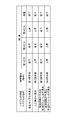
ここで、管理者は、想定する不具合の箇所に応じて、第1狭窄装置291~第4狭窄装置294のうち、いずれかの狭窄装置を選択する。管理者は、例えば、図4に示す表に基づいて、狭窄動作をさせる狭窄装置を選択する。
まず、図3に示すように、体外循環訓練中における所定のタイミングで、トラブル訓練が開始される。トラブル訓練は、以下の手順で進められる。
図3に示すように、ステップST1において、管理者は、管理者端末30に対して、いずれかの狭窄装置に対する狭窄指示を入力する。具体的には、ステップST1において、管理者端末30は、指示入力部310を介して、管理者からの狭窄指示を受け付ける。
ここで、管理者は、想定する不具合の箇所に応じて、第1狭窄装置291~第4狭窄装置294のうち、いずれかの狭窄装置を選択する。管理者は、例えば、図4に示す表に基づいて、狭窄動作をさせる狭窄装置を選択する。
続けて、ステップST2において、管理者端末30(狭窄指示部320)は、第1狭窄装置291から第4狭窄装置294のいずれかに対して、狭窄指示である第1指示~第4指示のいずれかを出力する。
続けて、ステップST3において、第1狭窄装置291~第4狭窄装置294のいずれかは、狭窄指示である第1指示~第4指示のいずれかを受け付ける。
続けて、ステップST4において、第1指示~第4指示のいずれかを受け付けた第1狭窄装置291~第4狭窄装置294のいずれかは、第1位置K1~第4位置K4のいずれかを狭窄させるよう動作する。
続けて、ステップST5において、体外循環装置20のいずれかの構成要素を不具合とするトラブルが模擬的に発生する。
続けて、ステップST6において、第1圧力センサ271~第3圧力センサ273それぞれは、第1圧力センサ位置S1~第3圧力センサ位置S3それぞれにおける模擬血液の圧力を検出する。
また、ステップST6において、流量センサ280は、流量センサ位置SFにおける模擬血液の流量を検出する。
また、ステップST6において、流量センサ280は、流量センサ位置SFにおける模擬血液の流量を検出する。
続けて、ステップST7において、第1圧力センサ271~第3圧力センサ273それぞれは、検出結果を人工心肺装置290に出力する。
また、ステップST7において、流量センサ280は、検出結果を人工心肺装置290に出力する。
また、ステップST7において、流量センサ280は、検出結果を人工心肺装置290に出力する。
続けて、ステップST8において、人工心肺装置290は、第1圧力センサ271~第3圧力センサ273による検出結果(圧力情報)、および流量センサ280による検出結果(流量情報)を表示する。
ここで、訓練者は、訓練者端末40(表示部420)に表示される患者の状態を示す各種情報を確認しつつ、人工心肺装置290に表示された第1圧力センサ271~第3圧力センサ273による検出結果(圧力情報)、および流量センサ280による検出結果(流量情報)に基づいて、トラブル内容(トラブル箇所)を認識する。訓練者は、例えば、図4の現象欄に示される圧力や流量の変化を把握し、トラブルの内容(トラブル箇所)を認識する。
具体的には、図4に示すように、訓練者は、第1圧力センサ271により検出される圧力(第1圧力)が低下傾向にあり、第2圧力センサ272により検出される圧力(第2圧力)が低下傾向にあり、第3圧力センサ273により検出される圧力(第3圧力)が上昇傾向にあり、流量センサ280により検出される流量が低下傾向にあった場合、送血ポンプ240の不具合によるトラブルが発生したことを認識する。
具体的には、図4に示すように、訓練者は、第1圧力センサ271により検出される圧力(第1圧力)が低下傾向にあり、第2圧力センサ272により検出される圧力(第2圧力)が低下傾向にあり、第3圧力センサ273により検出される圧力(第3圧力)が上昇傾向にあり、流量センサ280により検出される流量が低下傾向にあった場合、送血ポンプ240の不具合によるトラブルが発生したことを認識する。
また、訓練者は、第1圧力センサ271により検出される圧力(第1圧力)が上昇傾向にあり、第2圧力センサ272により検出される圧力(第2圧力)が低下傾向にあり、第3圧力センサ273により検出される圧力(第3圧力)が上昇傾向にあり、流量センサ280により検出される流量が低下傾向にあった場合、人工肺250の不具合によるトラブルが発生したことを認識する。
また、訓練者は、第1圧力センサ271により検出される圧力(第1圧力)が低下にあり、第2圧力センサ272により検出される圧力(第2圧力)が低下にあり、第3圧力センサ273により検出される圧力(第3圧力)が低下にあり、流量センサ280により検出される流量が低下傾向にあった場合、脱血回路210の不具合や脱血カニューレに関する不具合によるトラブルが発生したことを認識する。
また、訓練者は、第1圧力センサ271により検出される圧力(第1圧力)が上昇傾向にあり、第2圧力センサ272により検出される圧力(第2圧力)が上昇傾向にあり、第3圧力センサ273により検出される圧力(第3圧力)が上昇傾向にあり、流量センサ280により検出される流量が低下傾向にあった場合、送血回路220の不具合や送血カニューレに関する不具合によるトラブルが発生したことを認識する。そして、トラブル訓練は終了する。
本実施形態によれば、体外循環訓練システムは、体外循環装置を構成する要素の不具合を原因とするトラブルを模擬的に発生させることができる。これにより、本実施形態によれば、体外循環装置を構成する装置の不具合によるトラブルを再現可能な体外循環訓練システムを提供することができる。これにより、体外循環訓練システムは、生体側ではなく、体外循環装置側の不具合を原因とするトラブルに対する訓練に利用するこができる。
続けて、図5~図8により、第2実施形態における体外循環訓練システム1Aについて説明する。以下、第1実施形態と相違する点を中心に説明し、同様の構成については説明を省略する。
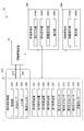
図5に示すように、本実施形態における体外循環訓練システム1Aは、模擬循環装置10と、体外循環装置20Aと、第1狭窄装置291、第2狭窄装置292、第5狭窄装置295、第6狭窄装置296および第7狭窄装置297と、第1圧力センサ271、第2圧力センサ272、第5圧力センサ275および第6圧力センサ276と、流量センサ280と、管理者端末30Aと、訓練者端末40Aと、を備える。
図5に示すように、本実施形態における体外循環訓練システム1Aは、模擬循環装置10と、体外循環装置20Aと、第1狭窄装置291、第2狭窄装置292、第5狭窄装置295、第6狭窄装置296および第7狭窄装置297と、第1圧力センサ271、第2圧力センサ272、第5圧力センサ275および第6圧力センサ276と、流量センサ280と、管理者端末30Aと、訓練者端末40Aと、を備える。
体外循環装置20Aは、模擬循環装置10に対して脱血可能かつ送血可能に接続される。体外循環装置20Aは、脱血回路210と、送血回路220と、人工肺250と、送血ポンプ240と、貯血部230と、動脈フィルター260と、を備える。
脱血回路210の構成は上述の通りである。脱血回路210上には、貯血部230と、第5狭窄装置295(第5a狭窄装置295aおよび第5b狭窄装置295b)と、第5圧力センサ275と、が配置される。
送血回路220の構成は上述の通りである。送血回路220上には、人工肺250と、動脈フィルター260と、第1狭窄装置291と、第2狭窄装置292と、第6狭窄装置296と、第7狭窄装置297と、第1圧力センサ271と、第2圧力センサ272と、第6圧力センサ276と、流量センサ280とが配置される。
貯血部230は、脱血回路210上に配置される。貯血部230は、模擬循環装置10から脱血された模擬血液を貯血する部分である。
動脈フィルター260は、送血回路220上における人工肺250よりも模擬循環装置10側に配置されるフィルターである。
送血ポンプ240は、本実施形態においては、人工肺250および動脈フィルター260を通して模擬循環装置10に模擬血液を戻す。
第1狭窄装置291および第2狭窄装置292の構成については、上述の通りである。
第5狭窄装置295は、脱血回路210における貯血部230よりも模擬循環装置10側の第5位置K5に配置される。本実施形態において、第5狭窄装置295は、第5a狭窄装置295aと第5b狭窄装置295bとにより構成される。第5狭窄装置295は、狭窄指示である第5指示により脱血回路210における第5位置K5を狭窄させる。第5a狭窄装置295aおよび第5b狭窄装置295bそれぞれは、脱血回路210における第5a位置K5aおよび第5b位置K5bそれぞれを狭窄させる。第5狭窄装置295は、例えば、脱血回路210や脱血カニューレの不具合によるトラブルを模擬的に発生させる場合、管理者端末30Aから第5指示を受ける。
第5狭窄装置295は、脱血回路210における貯血部230よりも模擬循環装置10側の第5位置K5に配置される。本実施形態において、第5狭窄装置295は、第5a狭窄装置295aと第5b狭窄装置295bとにより構成される。第5狭窄装置295は、狭窄指示である第5指示により脱血回路210における第5位置K5を狭窄させる。第5a狭窄装置295aおよび第5b狭窄装置295bそれぞれは、脱血回路210における第5a位置K5aおよび第5b位置K5bそれぞれを狭窄させる。第5狭窄装置295は、例えば、脱血回路210や脱血カニューレの不具合によるトラブルを模擬的に発生させる場合、管理者端末30Aから第5指示を受ける。
第6狭窄装置296は、送血回路220における動脈フィルター260よりも模擬循環装置10側の第6位置K6に配置される。第6狭窄装置296は、送血回路220における動脈フィルター260と後述の第7位置K7との間の第6位置K6に配置される。第6狭窄装置296は、管理者端末30Aからの狭窄指示である第6指示により送血回路220における第6位置K6を狭窄させる。第6狭窄装置296は、例えば、動脈フィルター260の不具合によるトラブルを模擬的に発生させる場合、管理者端末30Aから第6指示を受ける。
第7狭窄装置297は、送血回路220における第6位置K6より模擬循環装置10側の第7位置K7に配置される。第7狭窄装置297は、管理者端末30Aからの狭窄指示である第7指示により送血回路220における第7位置K7を狭窄させる。第7狭窄装置297は、例えば、送血回路220や送血カニューレの不具合によるトラブルを模擬的に発生させる場合、管理者端末30Aから第7指示を受ける。
第1圧力センサ271および第2圧力センサ272における構成は、上述の通りである。
第5圧力センサ275は、送血回路220における貯血部230と送血ポンプ240との間の第5圧力センサ位置S5において模擬血液の圧力を検出する。第5圧力センサ275により検出された結果は、人工心肺装置290に出力される。
第5圧力センサ275は、送血回路220における貯血部230と送血ポンプ240との間の第5圧力センサ位置S5において模擬血液の圧力を検出する。第5圧力センサ275により検出された結果は、人工心肺装置290に出力される。
第6圧力センサ276は、送血回路220における動脈フィルター260と第7位置K7との間の第6圧力センサ位置S6において模擬血液の圧力を検出する。第6圧力センサ276により検出された結果は、人工心肺装置290に出力される。
流量センサ280における構成は、上述の通りである。流量センサ280により検出された結果は、人工心肺装置290に出力される。
管理者端末30Aの構成は、上述の管理者端末30Aと同様である。管理者端末30Aは、第1狭窄装置291、第2狭窄装置292、第5狭窄装置295、第6狭窄装置296および第7狭窄装置297それぞれに対し、狭窄動作を指示する第1指示、第2指示、第5指示、第6指示および第7指示それぞれを出力可能に構成される。
訓練者端末40Aの構成は、上述の訓練者端末40と同様である。
訓練者端末40Aの構成は、上述の訓練者端末40と同様である。
続けて、図6より、体外循環訓練システム1Aにおける構成について、更に説明する。以下、主に体外循環訓練システム1Aにおける電気的な構成ついて説明する。
図6に示すように、管理者端末30Aは、上述の通り、第1狭窄装置291、第2狭窄装置292、第5狭窄装置295、第6狭窄装置296および第7狭窄装置297に対して、狭窄動作を指示する第1指示、第2指示、第5指示、第6指示および第7指示それぞれを出力可能に構成される。
図6に示すように、管理者端末30Aは、上述の通り、第1狭窄装置291、第2狭窄装置292、第5狭窄装置295、第6狭窄装置296および第7狭窄装置297に対して、狭窄動作を指示する第1指示、第2指示、第5指示、第6指示および第7指示それぞれを出力可能に構成される。
詳細には、図6に示すように、管理者端末30Aは、指示入力部310Aと、狭窄指示部320Aと、情報受付部330Aと、表示部340Aと、を備える。
指示入力部310Aは、第1指示、第2指示、第5指示、第6指示および第7指示を入力可能に構成される。具体的には、指示入力部310は、第1狭窄装置291、第2狭窄装置292、第5狭窄装置295、第6狭窄装置296および第7狭窄装置297のいずれかを選択する不図示の選択部と、選択部により選択された狭窄装置における狭窄度合いを指定する不図示の狭窄度合い指定部と、狭窄動作の実行を指示する不図示の実行指示部と、を有する。
指示入力部310Aは、第1指示、第2指示、第5指示、第6指示および第7指示を入力可能に構成される。具体的には、指示入力部310は、第1狭窄装置291、第2狭窄装置292、第5狭窄装置295、第6狭窄装置296および第7狭窄装置297のいずれかを選択する不図示の選択部と、選択部により選択された狭窄装置における狭窄度合いを指定する不図示の狭窄度合い指定部と、狭窄動作の実行を指示する不図示の実行指示部と、を有する。
狭窄指示部320Aは、第1狭窄装置291、第2狭窄装置292、第5狭窄装置295、第6狭窄装置296および第7狭窄装置297それぞれに対して、第1指示、第2指示、第5指示、第6指示および第7指示それぞれを出力可能に構成される。具体的には、狭窄指示部320Aは、上述の指示入力部310Aにより選択された狭窄装置に対して、狭窄度合い指定部により指定された狭窄度合いで狭窄させる指示(第1指示、第2指示、第5指示、第6指示および第7指示)を出力する。
情報受付部330Aは、模擬循環装置10において検出された検出結果を受け付ける。
表示部340Aは、模擬循環装置10に出力した指示の内容を表示する。
表示部340Aは、模擬循環装置10に出力した指示の内容を表示する。
訓練者端末40Aは、管理者端末30Aまたは模擬循環装置10から出力される血圧等の情報を表示可能に構成される。より具体的には、訓練者端末40は、表示部420を備え、この表示部420には、模擬循環装置10において模擬された患者の状態を示す各種情報(例えば、静脈コンプライアンス、抹消血管抵抗、動脈圧、中心静脈圧、肺動脈圧、循環血液流量、心拍数、不整脈、心拍出量等の血行動態、および血液ガス、ヘマトクリット、体温等の情報)が表示される。
訓練者は、訓練者端末40に表示される患者の状態を示す情報、並びに人工心肺装置290に表示された第1圧力センサ271、第2圧力センサ272、第5圧力センサ275および第6圧力センサ276からの圧力情報、および流量センサ280からの流量情報を確認し、体外循環装置20Aを構成する要素の不具合を認識する。
続けて、図7および図8により、体外循環訓練システム1Aのトラブル訓練時における作用を説明する。基本的な流れは、第1実施形態と同様である。
まず、図7に示すように、体外循環訓練中における所定のタイミングで、トラブル訓練が開始される。トラブル訓練は、以下の手順で進められる。
図7に示すように、ステップST11において、管理者は、管理者端末30Aに対して、いずれかの狭窄装置に対する狭窄指示を入力する。具体的には、ステップST11において、管理者端末30Aは、指示入力部310Aを介して、管理者からの狭窄指示を受け付ける。
ここで、管理者は、想定する不具合の箇所に応じて、第1狭窄装置291、第2狭窄装置292、第5狭窄装置295、第6狭窄装置296および第7狭窄装置297のうち、いずれかの狭窄装置を選択する。管理者は、例えば、図8に示す表に基づいて、狭窄動作をさせる狭窄装置を選択する。
まず、図7に示すように、体外循環訓練中における所定のタイミングで、トラブル訓練が開始される。トラブル訓練は、以下の手順で進められる。
図7に示すように、ステップST11において、管理者は、管理者端末30Aに対して、いずれかの狭窄装置に対する狭窄指示を入力する。具体的には、ステップST11において、管理者端末30Aは、指示入力部310Aを介して、管理者からの狭窄指示を受け付ける。
ここで、管理者は、想定する不具合の箇所に応じて、第1狭窄装置291、第2狭窄装置292、第5狭窄装置295、第6狭窄装置296および第7狭窄装置297のうち、いずれかの狭窄装置を選択する。管理者は、例えば、図8に示す表に基づいて、狭窄動作をさせる狭窄装置を選択する。
続けて、ステップST12において、管理者端末30A(狭窄指示部320A)は、第1狭窄装置291、第2狭窄装置292、第5狭窄装置295、第6狭窄装置296および第7狭窄装置297のいずれかに対して、狭窄指示である第1指示、第2指示、第5指示、第6指示および第7指示のいずれかを出力する。
続けて、ステップST13において、第1狭窄装置291、第2狭窄装置292、第5狭窄装置295、第6狭窄装置296および第7狭窄装置297のいずれかは、狭窄指示である第1指示、第2指示、第5指示、第6指示および第7指示のいずれかを受け付ける。
続けて、ステップST14において、第1指示、第2指示、第5指示、第6指示および第7指示のいずれかを受け付けた第1狭窄装置291、第2狭窄装置292、第5狭窄装置295、第6狭窄装置296および第7狭窄装置297のいずれかは、第1位置K1、第2位置K2、第5位置K5、第6位置K6および第7位置K7のいずれかを狭窄させるよう動作する。
続けて、ステップST15において、体外循環装置20Aのいずれかの構成要素を不具合とするトラブルが模擬的に発生する。
続けて、ステップST16において、第1圧力センサ271、第2圧力センサ272、第5圧力センサ275および第6圧力センサ276それぞれは、第1圧力センサ位置S1、第2圧力センサ位置S2、第5圧力センサ位置S5、第6圧力センサ位置S6それぞれにおける模擬血液の圧力を検出する。
また、ステップST16において、流量センサ280は、流量センサ位置SFにおける模擬血液の流量を検出する。
また、ステップST16において、流量センサ280は、流量センサ位置SFにおける模擬血液の流量を検出する。
続けて、ステップST17において、第1圧力センサ271、第2圧力センサ272、第5圧力センサ275および第6圧力センサ276それぞれは、検出結果を人工心肺装置290に出力する。
また、ステップST17において、流量センサ280は、検出結果を人工心肺装置290に出力する。
また、ステップST17において、流量センサ280は、検出結果を人工心肺装置290に出力する。
続けて、ステップST18において、人工心肺装置290は、第1圧力センサ271、第2圧力センサ272、第5圧力センサ275および第6圧力センサ276による検出結果(圧力情報)、および流量センサ280による検出結果(流量情報)を表示する。
ここで、訓練者は、訓練者端末40(表示部420)に表示される患者の状態を示す各種情報を確認しつつ、人工心肺装置290に表示された第1圧力センサ271、第2圧力センサ272、第5圧力センサ275および第6圧力センサ276による検出結果(圧力情報)、および流量センサ280による検出結果(流量情報)に基づいて、トラブル内容(トラブル箇所)を認識する。訓練者は、例えば、図8の現象欄に示される圧力や流量の変化を把握し、トラブルの内容(トラブル箇所)を認識する。
ここで、訓練者は、訓練者端末40(表示部420)に表示される患者の状態を示す各種情報を確認しつつ、人工心肺装置290に表示された第1圧力センサ271、第2圧力センサ272、第5圧力センサ275および第6圧力センサ276による検出結果(圧力情報)、および流量センサ280による検出結果(流量情報)に基づいて、トラブル内容(トラブル箇所)を認識する。訓練者は、例えば、図8の現象欄に示される圧力や流量の変化を把握し、トラブルの内容(トラブル箇所)を認識する。
具体的には、図8に示すように、訓練者は、第1圧力センサ271により検出される圧力(第1圧力)が低下傾向にあり、第2圧力センサ272により検出される圧力(第2圧力)が低下傾向にあり、第5圧力センサ275により検出される圧力(第5圧力)が上昇傾向にあり、第6圧力センサ276により検出される圧力(第6圧力)が低下傾向にあり、流量センサ280により検出される流量が低下傾向にあった場合、送血ポンプ240の不具合によるトラブルが発生したことを認識する。
また、訓練者は、第1圧力センサ271により検出される圧力(第1圧力)が上昇傾向にあり、第2圧力センサ272により検出される圧力(第2圧力)が低下傾向にあり、第5圧力センサ275により検出される圧力(第5圧力)が上昇傾向にあり、第6圧力センサ276により検出される圧力(第6圧力)が低下傾向にあり、流量センサ280により検出される流量が低下傾向にあった場合、人工肺250の不具合によるトラブルが発生したことを認識する。
また、訓練者は、第1圧力センサ271により検出される圧力(第1圧力)が変化なく、第2圧力センサ272により検出される圧力(第2圧力)が変化なく、第5圧力センサ275により検出される圧力(第5圧力)が変化なく、第6圧力センサ276により検出される圧力(第6圧力)が変化なく、流量センサ280により検出される流量が変化ない場合において貯血部230に貯留された模擬血液レベル(液位)が低下した場合、脱血回路210の不具合や脱血カニューレに関する不具合によるトラブルが発生したことを認識する。
また、訓練者は、第1圧力センサ271により検出される圧力(第1圧力)が上昇傾向にあり、第2圧力センサ272により検出される圧力(第2圧力)が上昇傾向にあり、第5圧力センサ275により検出される圧力(第5圧力)が上昇傾向にあり、第6圧力センサ276により検出される圧力(第6圧力)が低下傾向にあり、流量センサ280により検出される流量が低下傾向にあった場合、動脈フィルター260の不具合によるトラブルが発生したことを認識する。
また、訓練者は、第1圧力センサ271により検出される圧力(第1圧力)が上昇傾向にあり、第2圧力センサ272により検出される圧力(第2圧力)が上昇傾向にあり、第5圧力センサ275により検出される圧力(第5圧力)が上昇傾向にあり、第6圧力センサ276により検出される圧力(第6圧力)が上昇傾向にあり、流量センサ280により検出される流量が低下傾向にあった場合、送血回路220の不具合や送血カニューレに関する不具合によるトラブルが発生したことを認識する。そして、トラブル訓練は終了する。
本実施形態によれば、第1実施形態と同様に、体外循環訓練システムは、体外循環装置を構成する要素の不具合を原因とするトラブルを模擬的に発生させることができる。これにより、本実施形態によれば、体外循環装置を構成する装置の不具合によるトラブルを再現可能な体外循環訓練システムを提供することができる。これにより、体外循環訓練システムは、生体側ではなく、体外循環装置側の不具合を原因とするトラブルに対する訓練に利用するこができる。
また、本実施形態によれば、狭窄装置や圧力センサの数と配置とを調整することで、体外循環装置を構成する要素が増加した場合でも、当該要素の不具合を特定可能に構成される。これにより、本実施形態によれば、体外循環訓練システムは、多くの構成要素を備える体外循環装置における体外循環装置側の不具合を原因とするトラブルに対する訓練に利用するこができる。
また、本実施形態によれば、狭窄装置や圧力センサの数と配置とを調整することで、体外循環装置を構成する要素が増加した場合でも、当該要素の不具合を特定可能に構成される。これにより、本実施形態によれば、体外循環訓練システムは、多くの構成要素を備える体外循環装置における体外循環装置側の不具合を原因とするトラブルに対する訓練に利用するこができる。
上述の実施形態においては、体外循環訓練システムは、圧力センサにおける検出結果および流量センサにおける検出結果が各端末において表示されるよう構成されるが、これに限定されない。体外循環訓練システムは、例えば、圧力センサにおける検出結果および流量センサにおける検出結果が各端末において音声により外部に報知されるよう構成されていてもよい。
また、上述の実施形態においては、狭窄装置は、各回路を構成する回路チューブに対して外部から力を加えて変形させることで狭窄させているが、これに限定されず、各回路を構成する回路チューブ等の内部に配置され、模擬血液が通る内径の大きさを調整するよう構成されていてもよい。
また、上述の実施形態においては、流量センサSFは、送血回路220における送血ポンプ240と第1位置K1との間に配置されているが、これに限定されず、送血回路220における送血ポンプよりも下流側のいずれの位置(例えば、人工肺250よりも下流側)に配置されていてもよい。
1 体外循環訓練システム
10 模擬循環装置
20 体外循環装置
30 管理者端末
40 訓練者端末
210 脱血回路
220 送血回路
230 貯血部
240 送血ポンプ
250 人工肺
260 動脈フィルター
271 第1圧力センサ
272 第2圧力センサ
273 第3圧力センサ
280 流量センサ
291 第1狭窄装置
292 第2狭窄装置
293 第3狭窄装置
294 第4狭窄装置
320 狭窄指示部
340 表示部
410 情報受付部
420 表示部
10 模擬循環装置
20 体外循環装置
30 管理者端末
40 訓練者端末
210 脱血回路
220 送血回路
230 貯血部
240 送血ポンプ
250 人工肺
260 動脈フィルター
271 第1圧力センサ
272 第2圧力センサ
273 第3圧力センサ
280 流量センサ
291 第1狭窄装置
292 第2狭窄装置
293 第3狭窄装置
294 第4狭窄装置
320 狭窄指示部
340 表示部
410 情報受付部
420 表示部
Claims (8)
- 生体の血行動態を模擬する模擬循環装置と、
前記模擬循環装置に対して脱血可能かつ送血可能に接続される体外循環装置であって、
前記模擬循環装置から模擬血液を脱血する脱血回路と、
前記脱血回路からの模擬血液を模擬循環装置に戻す送血回路と、
前記送血回路上に配置される人工肺と、
前記送血回路と前記脱血回路とを連結すると共に、前記脱血回路からの模擬血液を前記送血回路に送血することで前記人工肺を通して前記模擬循環装置に模擬血液を戻す送血ポンプと、を備える体外循環装置と、
前記送血回路上における前記人工肺よりも前記送血ポンプ側の第1位置に配置され、第1指示により前記送血回路における前記第1位置を狭窄させる第1狭窄装置と、
前記送血回路上における前記人工肺よりも前記模擬循環装置側の第2位置に配置され、第2指示により前記送血回路における前記第2位置を狭窄させる第2狭窄装置と、
前記第1狭窄装置および/または前記第2狭窄装置に対して、前記第1指示および/または前記第2指示を出力可能な狭窄指示部と、
前記送血回路における前記第1位置と前記人工肺との間の第1圧力センサ位置において模擬血液の圧力を検出する第1圧力センサと、
前記送血回路における前記第2位置と前記模擬循環装置との間の第2圧力センサ位置において模擬血液の圧力を検出する第2圧力センサと、
前記送血回路における流量センサ位置において模擬血液の流量を検出する流量センサと、
前記第1圧力センサ、前記第2圧力センサおよび前記流量センサの検出結果を報知する報知部と、を備える体外循環訓練システム。 - 前記脱血回路における第3位置に配置され、第3指示により前記脱血回路における前記第3位置を狭窄させる第3狭窄装置と、
前記送血回路における前記第2圧力センサ位置より前記模擬循環装置側の第4位置に配置され、第4指示により前記送血回路における前記第4位置を狭窄させる第4狭窄装置と、
前記脱血回路における前記第3位置と前記送血ポンプとの間の第3圧力センサ位置において模擬血液の圧力を検出する第3圧力センサと、を更に備え、
前記狭窄指示部は、前記第3狭窄装置および/または前記第4狭窄装置に対して、前記第3指示および/または前記第4指示を更に出力可能であり、
前記報知部は、前記第3圧力センサの検出結果を更に報知する請求項1に記載の体外循環訓練システム。 - 前記第1指示、前記第2指示、前記第3指示、および前記第4指示が入力可能な指示入力部、および前記狭窄指示部を有する管理者端末と、
前記模擬循環装置または前記管理者端末から出力された情報の一部を表示する表示部を有する訓練者端末と、を更に備える請求項2に記載の体外循環訓練システム。 - 前記報知部により報知された前記第1圧力センサ、前記第2圧力センサ、前記第3圧力センサおよび前記流量センサによる検出結果に基づいて、前記体外循環装置におけるトラブルを認識可能に構成される請求項2または3に記載の体外循環訓練システム。
- 生体の血行動態を模擬する模擬循環装置と、
前記模擬循環装置に対して脱血可能かつ送血可能に接続される体外循環装置であって、
前記模擬循環装置から模擬血液を脱血する脱血回路と、
前記脱血回路からの模擬血液を模擬循環装置に戻す送血回路と、
前記脱血回路上に配置され、前記模擬循環装置から脱血された模擬血液を貯血する貯血部と、
前記送血回路上に配置される人工肺と、
前記送血回路上における前記人工肺よりも前記模擬循環装置側に配置される動脈フィルターと、
前記脱血回路と前記送血回路とを連結すると共に、前記脱血回路からの模擬血液を前記送血回路に送血することで前記人工肺および前記動脈フィルターを通して前記模擬循環装置に模擬血液を戻す送血ポンプと、を備える体外循環装置と、
前記送血回路上における前記人工肺よりも前記送血ポンプ側の第1位置に配置され、第1指示により前記送血回路における前記第1位置を狭窄させる第1狭窄装置と、
前記送血回路上における前記人工肺よりも前記模擬循環装置側の第2位置に配置され、第2指示により前記送血回路における前記第2位置を狭窄させる第2狭窄装置と、
前記第1狭窄装置および/または前記第2狭窄装置に対して、前記第1指示および/または前記第2指示を出力可能な狭窄指示部と、
前記送血回路における前記第1位置と前記人工肺との間の第1圧力センサ位置において模擬血液の圧力を検出する第1圧力センサと、
前記送血回路における前記第2位置と前記動脈フィルターとの間の第2圧力センサ位置において模擬血液の圧力を検出する第2圧力センサと、
前記送血回路における流量センサ位置において模擬血液の流量を検出する流量センサと、
前記第1圧力センサ、前記第2圧力センサおよび流量センサの検出結果を報知する報知部と、を備える体外循環訓練システム。 - 前記脱血回路における前記貯血部よりも模擬循環装置側の第5位置に配置され、第5指示により前記脱血回路における前記第5位置を狭窄させる第5狭窄装置と、
前記送血回路における前記動脈フィルターよりも前記模擬循環装置側の第6位置に配置され、第6指示により前記送血回路における前記第6位置を狭窄させる第6狭窄装置と、
前記送血回路における前記第6位置より前記模擬循環装置側の第7位置に配置され、第7指示により前記送血回路における前記第7位置を狭窄させる第7狭窄装置と、
前記送血回路における前記貯血部と前記送血ポンプとの間の第5圧力センサ位置において模擬血液の圧力を検出する第5圧力センサと、
前記送血回路における前記動脈フィルターと前記第7位置との間の第6圧力センサ位置において模擬血液の圧力を検出する第6圧力センサと、を更に備え、
前記狭窄指示部は、前記第5狭窄装置、前記第6狭窄装置および前記第7狭窄装置のいずれか1以上に対して、前記第5指示、前記第6指示および第7指示のいずれか1以上を更に出力可能であり、
前記報知部は、前記第5圧力センサおよび前記第6圧力センサの検出結果を更に報知する請求項5に記載の体外循環訓練システム。 - 前記第1指示、前記第2指示、前記第5指示、前記第6指示および第7指示が入力可能な指示入力部、および前記狭窄指示部を有する管理者端末と、
前記模擬循環装置または前記管理者端末から出力された情報の一部を表示する表示部を有する訓練者端末と、を更に備える請求項6に記載の体外循環訓練システム。 - 前記報知部により報知された前記第1圧力センサ、前記第2圧力センサ、前記第5圧力センサ、前記第6圧力センサおよび前記流量センサによる検出結果に基づいて、前記体外循環装置におけるトラブルを認識可能に構成される請求項6または7に記載の体外循環訓練システム。
Priority Applications (2)
| Application Number | Priority Date | Filing Date | Title |
|---|---|---|---|
| CN201680030829.3A CN107615361B (zh) | 2015-09-07 | 2016-09-05 | 体外循环训练系统 |
| HK18109189.2A HK1249797B (zh) | 2015-09-07 | 2016-09-05 | 体外循环训练系统 |
Applications Claiming Priority (2)
| Application Number | Priority Date | Filing Date | Title |
|---|---|---|---|
| JP2015175771A JP6582768B2 (ja) | 2015-09-07 | 2015-09-07 | 体外循環訓練システム |
| JP2015-175771 | 2015-09-07 |
Publications (1)
| Publication Number | Publication Date |
|---|---|
| WO2017043440A1 true WO2017043440A1 (ja) | 2017-03-16 |
Family
ID=58239773
Family Applications (1)
| Application Number | Title | Priority Date | Filing Date |
|---|---|---|---|
| PCT/JP2016/075977 Ceased WO2017043440A1 (ja) | 2015-09-07 | 2016-09-05 | 体外循環訓練システム |
Country Status (3)
| Country | Link |
|---|---|
| JP (1) | JP6582768B2 (ja) |
| CN (1) | CN107615361B (ja) |
| WO (1) | WO2017043440A1 (ja) |
Cited By (2)
| Publication number | Priority date | Publication date | Assignee | Title |
|---|---|---|---|---|
| US12374236B2 (en) | 2022-01-27 | 2025-07-29 | Fresenius Medical Care Holdings, Inc. | Dialysis training using dialysis treatment simulation system |
| US12502465B2 (en) | 2022-03-30 | 2025-12-23 | Fresenius Medical Care Holdings, Inc. | Dialysis treatment file simulation and verification system |
Families Citing this family (3)
| Publication number | Priority date | Publication date | Assignee | Title |
|---|---|---|---|---|
| KR102342717B1 (ko) * | 2019-10-28 | 2021-12-27 | 김정연 | 교육용 체외혈액순환기 |
| JP7589799B2 (ja) * | 2021-03-26 | 2024-11-26 | 株式会社ジェイ・エム・エス | 血液循環回路 |
| CN116439871B (zh) * | 2023-04-28 | 2024-03-01 | 天津大学温州安全(应急)研究院 | 一种用于动物的ecmo实验装置及其方法 |
Citations (3)
| Publication number | Priority date | Publication date | Assignee | Title |
|---|---|---|---|---|
| JP2009217042A (ja) * | 2008-03-11 | 2009-09-24 | Hiroshima Univ | 体外循環装置用の訓練装置およびそのプログラム |
| US20090305214A1 (en) * | 2005-11-30 | 2009-12-10 | Andrew Pybus | Perfusion Method and Apparatus |
| JP2010259525A (ja) * | 2009-04-30 | 2010-11-18 | Asahi Kasei Kuraray Medical Co Ltd | 体外循環装置のシミュレーション装置及び体外循環装置のシミュレーションモジュール |
Family Cites Families (3)
| Publication number | Priority date | Publication date | Assignee | Title |
|---|---|---|---|---|
| JP3774769B2 (ja) * | 2003-10-02 | 2006-05-17 | 国立大学法人広島大学 | 体外循環装置用の訓練装置、およびそのプログラム |
| JP2005143813A (ja) * | 2003-11-14 | 2005-06-09 | Yoshinari Niimi | 体外循環用人体シミュレーション装置 |
| EP3231461B1 (en) * | 2014-12-12 | 2019-08-14 | Terumo Kabushiki Kaisha | Extracorporeal circulation device |
-
2015
- 2015-09-07 JP JP2015175771A patent/JP6582768B2/ja active Active
-
2016
- 2016-09-05 CN CN201680030829.3A patent/CN107615361B/zh active Active
- 2016-09-05 WO PCT/JP2016/075977 patent/WO2017043440A1/ja not_active Ceased
Patent Citations (3)
| Publication number | Priority date | Publication date | Assignee | Title |
|---|---|---|---|---|
| US20090305214A1 (en) * | 2005-11-30 | 2009-12-10 | Andrew Pybus | Perfusion Method and Apparatus |
| JP2009217042A (ja) * | 2008-03-11 | 2009-09-24 | Hiroshima Univ | 体外循環装置用の訓練装置およびそのプログラム |
| JP2010259525A (ja) * | 2009-04-30 | 2010-11-18 | Asahi Kasei Kuraray Medical Co Ltd | 体外循環装置のシミュレーション装置及び体外循環装置のシミュレーションモジュール |
Cited By (2)
| Publication number | Priority date | Publication date | Assignee | Title |
|---|---|---|---|---|
| US12374236B2 (en) | 2022-01-27 | 2025-07-29 | Fresenius Medical Care Holdings, Inc. | Dialysis training using dialysis treatment simulation system |
| US12502465B2 (en) | 2022-03-30 | 2025-12-23 | Fresenius Medical Care Holdings, Inc. | Dialysis treatment file simulation and verification system |
Also Published As
| Publication number | Publication date |
|---|---|
| JP2017053896A (ja) | 2017-03-16 |
| CN107615361B (zh) | 2019-11-12 |
| CN107615361A (zh) | 2018-01-19 |
| HK1249797A1 (zh) | 2018-11-09 |
| JP6582768B2 (ja) | 2019-10-02 |
Similar Documents
| Publication | Publication Date | Title |
|---|---|---|
| JP6582768B2 (ja) | 体外循環訓練システム | |
| US11466235B2 (en) | Method for a simulation and evaluation system for medical treatment facilities | |
| US9589483B2 (en) | System for simulating diagnostic features of tension pneumothorax and cardiac tamponade within a medical training manikin | |
| Al Disi et al. | Extracorporeal membrane oxygenation simulation-based training: methods, drawbacks and a novel solution | |
| EP3284073B1 (en) | Devices and methods for dynamic extracorporeal membrane oxygenation simulation | |
| WO2015187616A1 (en) | Device for extracorporeal membrane oxygenation cardio-pulmonary resuscitation training and vascular cut down trainer | |
| Fitzgerald et al. | Staffing, equipment, monitoring considerations for extracorporeal membrane oxygenation | |
| Maddry et al. | Development and evaluation of an abbreviated extracorporeal membrane oxygenation (ECMO) course for nonsurgical physicians and nurses | |
| Keller et al. | Design of a cost-effective, hemodynamically adjustable model for resuscitative endovascular balloon occlusion of the aorta (REBOA) simulation | |
| JP7293355B2 (ja) | 心機能測定システム、体外循環装置および心機能測定プログラム | |
| US20170278431A1 (en) | Central Pressurized Cadaver Model | |
| McCoach et al. | Pediatric extracorporeal life support systems: education and training at Penn State Hershey Children's Hospital | |
| CN117950192B (zh) | 一种基于vr的仿真ecmo操作方法 | |
| CN119889114A (zh) | 一种体外膜肺氧合vr培训系统 | |
| Matte | It is time to update membrane oxygenator testing standards and their instructions for use | |
| HK1249797B (zh) | 体外循环训练系统 | |
| JP4867001B2 (ja) | 体外循環装置用の訓練装置 | |
| Mahmoud et al. | Preliminary implementation of the next generation cannulation simulator | |
| CN117934231B (zh) | 一种基于vr的ecmo导丝扩张操作方法 | |
| EP3363480A1 (de) | Flüssigkeitssystem für ein simulations- und evaluierungssystem für medizinische behandlungseinrichtungen | |
| EP3364321A1 (de) | Medizintechnisches gerät für ein simulations- und evaluierungssystem für medizinische behandlungseinrichtungen | |
| EP3364319A1 (de) | Verfahren für ein simulations- und evaluierungssystem für medizinische behandlungseinrichtungen | |
| EP3364322A1 (de) | Vorrichtung und verfahren für ein simulations- und evaluierungssystem für medizinische behandlungseinrichtungen | |
| White et al. | Emergent cardiopulmonary bypass during Cardiac Surgery | |
| Vachharajani et al. | How is arteriovenous fistula longevity best prolonged? |
Legal Events
| Date | Code | Title | Description |
|---|---|---|---|
| 121 | Ep: the epo has been informed by wipo that ep was designated in this application |
Ref document number: 16844301 Country of ref document: EP Kind code of ref document: A1 |
|
| NENP | Non-entry into the national phase |
Ref country code: DE |
|
| 122 | Ep: pct application non-entry in european phase |
Ref document number: 16844301 Country of ref document: EP Kind code of ref document: A1 |