WO2017038197A1 - 組立型模型 - Google Patents
組立型模型 Download PDFInfo
- Publication number
- WO2017038197A1 WO2017038197A1 PCT/JP2016/067332 JP2016067332W WO2017038197A1 WO 2017038197 A1 WO2017038197 A1 WO 2017038197A1 JP 2016067332 W JP2016067332 W JP 2016067332W WO 2017038197 A1 WO2017038197 A1 WO 2017038197A1
- Authority
- WO
- WIPO (PCT)
- Prior art keywords
- block
- model
- assembly
- connecting blocks
- motor
- Prior art date
- Legal status (The legal status is an assumption and is not a legal conclusion. Google has not performed a legal analysis and makes no representation as to the accuracy of the status listed.)
- Ceased
Links
Images










Classifications
-
- A—HUMAN NECESSITIES
- A63—SPORTS; GAMES; AMUSEMENTS
- A63H—TOYS, e.g. TOPS, DOLLS, HOOPS OR BUILDING BLOCKS
- A63H17/00—Toy vehicles, e.g. with self-drive; ; Cranes, winches or the like; Accessories therefor
- A63H17/26—Details; Accessories
-
- A—HUMAN NECESSITIES
- A63—SPORTS; GAMES; AMUSEMENTS
- A63H—TOYS, e.g. TOPS, DOLLS, HOOPS OR BUILDING BLOCKS
- A63H29/00—Drive mechanisms for toys in general
- A63H29/22—Electric drives
-
- A—HUMAN NECESSITIES
- A63—SPORTS; GAMES; AMUSEMENTS
- A63H—TOYS, e.g. TOPS, DOLLS, HOOPS OR BUILDING BLOCKS
- A63H33/00—Other toys
- A63H33/04—Building blocks, strips, or similar building parts
- A63H33/06—Building blocks, strips, or similar building parts to be assembled without the use of additional elements
- A63H33/08—Building blocks, strips, or similar building parts to be assembled without the use of additional elements provided with complementary holes, grooves, or protuberances, e.g. dovetails
Definitions
- the present invention relates to an assembly type model.
- An assembly type model in which a user assembles and completes a model is known.
- an assembly that pivotally supports left and right front wheels and an assembly that pivotally supports left and right rear wheels and incorporates a motor correspond to a vehicle floor structure.
- An assembly type model of an automobile that is assembled by being inserted from above with respect to a vehicle body and is mounted with a battery and then running is disclosed.
- These car-assembled models are mainly used to run each other's cars on a dedicated course and play a simple race, and enjoy remodeling by replacing some components such as motors with optional tune-up parts. You can also taste.
- the present invention has been devised in view of the above circumstances.
- the purpose is to provide a technique for realizing a completely new assembly model different from the conventional one.
- the assembly type model of the present invention is an assembly type model configured by assembling N (N ⁇ 2) connection blocks to a foundation block, and the foundation block sequentially slides the connection blocks in a predetermined sliding direction.
- the connecting blocks are detachable by engaging with each other, and when the connecting blocks are attached to the basic block in a predetermined connecting order, the adjacent connecting blocks are adapted to each other.
- the retaining block fitted into the connecting block at the end and the foundation block to prevent the coupling block from coming off Is preferably further provided.
- the retaining block is assembled so as to penetrate the terminal connecting block and the base block in a direction intersecting the sliding direction, so that the N pieces mounted are mounted. It preferably functions as a retaining block for the connecting block.
- a cover that covers the foundation block on the state where the N connecting blocks and the retaining block are mounted, and for fixing the cover to the retaining block. It is preferable to further include a locking body.
- the N connecting blocks include a battery mounting block (for example, the center block 300 in FIG. 2) for mounting a battery, and the battery mounting block is mounted. It has a lid part that covers the battery and a locking part that locks the lid part, and the locking body preferably also serves as a tool for locking and unlocking the locking part.
- a battery mounting block for example, the center block 300 in FIG. 2
- the battery mounting block is mounted. It has a lid part that covers the battery and a locking part that locks the lid part, and the locking body preferably also serves as a tool for locking and unlocking the locking part.
- the N connecting blocks include a drive block (for example, the rear block 400 in FIG. 2) on which a drive shaft, a motor unit, and a gear unit are mounted.
- the block has a position where the drive shaft is disposed as a fixed position, and the motor unit can be replaced with another type of motor unit, and the gear unit includes the driving force of the mounted motor unit at the fixed position. It is preferable to have a gear portion that can be transmitted to the drive shaft and can be replaced with a gear portion having a gear ratio corresponding to the mounted motor portion.
- the assembly model of the present invention includes N (N ⁇ 2) connecting blocks including a driving block (for example, the rear block 400 in FIG. 2) on which a driving shaft, a motor unit, and a gear unit are mounted on a basic block.
- the drive block has the drive shaft arranged at a fixed position, and the motor unit can be replaced with another type of motor unit, and the gear unit
- the drive force of the mounted motor unit can be transmitted to the drive shaft at the fixed position, and can be replaced with a gear unit of a type having a gear ratio according to the mounted motor unit.
- the gear unit is configured by a combination of a plurality of gears according to the inter-axis distance between the rotation shaft of the mounted motor unit and the drive shaft.
- the motor unit includes a motor and a replaceable case that accommodates the motor, and the distance between the shafts with respect to the drive shaft differs when the case is replaced. It is preferable to configure another type of motor unit.
- the N connecting blocks include a front wheel block (for example, the front block 200 in FIG. 2) for pivotally supporting the left and right wheels for the front wheel, and the left and right blocks for the rear wheel.
- a rear wheel block for example, the rear block 400 in FIG. 2) for pivotally supporting the wheel is included, and it is preferably a model of a moving body.
- any one of the N connection blocks preferably serves as a tool for fixing the wheel to a pivot (for example, the rear wheel shaft 404 in FIG. 19).
- the perspective external view which shows the external appearance example of the completion state of an assembly type model.
- Perspective view of the front block in the assembled state as seen from diagonally below the left front of the model It is a 5th view of a center block, (1) Front view, (2) Top view, (3) Rear view, (4) Left side view, (5) Bottom view (Back view).
- the perspective external view which looked up at the center block from diagonally lower left front of the block It is a 5th page figure which shows the structural example of a rear block, Comprising: (1) Front view, (2) Top view, (3) Rear view, (4) Left side view, (5) Bottom view (Back view).
- FIG. 1 It is a figure which shows the structural example of a retaining block, Comprising: (1) Top view, (2) Front view, (3) DD sectional drawing.
- the left view of the block which shows the modification of a basic block.
- FIG. 1 is a perspective external view showing an example of an external appearance of an assembled model to which the present invention is applied.
- the assembly type model 3 of the present embodiment is a model of a four-wheeled vehicle type moving body that is assembled by a user himself / herself and includes parts included in a sales package. By preparing differently designed covers 5 (integrated cowls) for each package, it is possible to provide different vehicle types even for the same vehicle type.
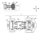
- FIG. 2 is a top view of the assembly model 3 with the cover 5 removed, and shows the vehicle body portion covered with the cover 5.
- FIG. 3 is a side view of the vehicle body viewed from the right side of the front of the model. Note that a simplified diagram of the structure is added to the upper left of these drawings.
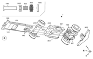
- FIG. 4 is an exploded view of the vehicle body seen from the front diagonally below.
- the vehicle body portion 7 of the assembly model 3 is configured such that a plurality of connecting blocks can be assembled and disassembled to the base block 100 in a predetermined connecting order.
- the connection block of this embodiment is a front block 200, a center block 300, a rear block 400, and a retaining block 500.
- the base block 100 is a thin plate-like structure that is long along the traveling direction (front-rear direction) of the assembled model 3, and also serves as a vehicle front bumper and a vehicle body floor structure in terms of design.
- the front block 200 is a front wheel block that pivotally supports the left and right wheels 203R and 203L that are front wheels.
- the center block 300 is a battery mounting block on which the battery 8 is mounted.
- the rear block 400 is a rear-wheel block and drive block that pivotally supports the left and right wheels 403R and 403L serving as rear wheels and incorporates drive system components such as the motor 420.
- the retaining block 500 is a part that fits to the base block 100 and the rear block 400 that is a terminal block when connected from a direction crossing the vehicle body longitudinal direction, and the rear bumper of the vehicle is designed in terms of design. I also serve.
- first rails 101 are extended along the longitudinal direction of the vehicle body on the left and right side surfaces of the foundation block 100.
- the front block 200 and the center block 300 are respectively provided with a front rail guide 201 and a center rail guide 301 that are slidably engaged with the first rail 101.
- a relatively short second rail 401 projects from the bottom surface of the rear block 400, and a rear rail guide 140 that slidably engages with the second rail 401 is provided at the rear of the base block 100. ing.
- the basic block 100 plays a role of a kind of spine / keel, and the three connecting blocks of the front block 200, the center block 300, and the rear block 400 are arranged along the vehicle longitudinal direction (sliding direction).
- the skewer is integrally slidably inserted, and the retaining block 500 prevents the three connecting blocks from being detached from the basic block 100.
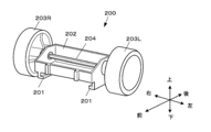
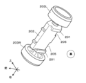
- FIG. 5 and 6 are perspective views of the front block 200 in the assembled state.
- FIG. 5 is a perspective external view of the model as seen from the upper left diagonally of the model, and
- FIG. It is an external view.
- the front block 200 pivotally supports a box-shaped block main body 202 that opens upward by connecting the left front wheel 203L and the right front wheel 203R with a front wheel shaft 204 (pivot).
- a front rail guide 201 is projected from the left and right edges of the lower surface (back surface) of the block main body 202 along the vehicle body front-rear direction (slide direction).
- the front rail guide 201 of the present embodiment is composed of a pair of left and right.
- the front rail guide 201 When the front rail guide 201 provided on the right side for the block is viewed from the front, the front rail guide 201 has a cross section (also referred to as an L-shape in front view) that extends downward and is bent to the right (inside).
- the front rail guide 201 on the left side for the block has a cross section (also referred to as an L-shape that is reversed left and right when viewed from the front) after extending downward and bending to the left (inside).
- the pair of left and right front rail guides 201 are sized so as to be freely slidably fitted to the first rail 101 of the base block 100 so as to generate appropriate operation resistance.
- the front rail guide 201 is divided into left and right parts so that the lower surface (bottom surface) of the foundation block 100 can be seen after assembly, but the left and right front rail guides 201 are integrated to form the front block 200. You may implement
- a fitting concave portion 205 having a shape that fits the front portion of the center block 300 adjacent to the rear in the assembled state of the vehicle body portion 7 is provided.
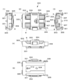
- FIG. 7 is a five-side view of the center block 300, (1) front view, (2) top view, (3) rear view, (4) left side view, and (5) bottom view (back view). is there.
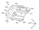
- FIG. 8 is a perspective external view of the center block 300 as viewed from diagonally below the left rear of the block.
- FIG. 9 is a perspective external view of the center block 300 as viewed from diagonally below the left front of the block.
- the center block 300 is a battery mounting block in which two batteries 8 are accommodated in the battery accommodating portion 302 opened upward, and the upper portion of the accommodated battery 8 is covered and fixed by the lid portion 303.
- the lid portion 303 is provided with a locking portion 304 so that it can be locked.
- the battery housing 302 has a built-in switch terminal (not shown) that also serves as a connection terminal for connecting the front ends of the accommodated batteries 8, and a switch terminal is provided on the lower surface (bottom surface / back surface) of the battery housing 302.
- a switch lever 310 for turning ON / OFF is projected.
- Center rail guides 301 are provided along the longitudinal direction of the vehicle body (sliding direction) at the left and right edge portions of the lower surface of the center block 300.
- the center rail guide 301 of this embodiment is comprised by the left-right pair.
- the center rail guide 301 When the center rail guide 301 provided on the right side for the block is viewed from the front, the center rail guide 301 has a cross section (also referred to as L-shaped in front view) that extends downward and is bent to the right.
- the center rail guide 301 provided on the left side for the block has a cross-section (also referred to as an L-shape that is reversed left and right when viewed from the front) after extending downward.
- the pair of left and right center rail guides 301 are sized so as to be slidably fitted to the first rail 101 of the foundation block 100 so as to generate an appropriate operating resistance.
- the center rail guide 301 is divided into left and right parts so that the lower surface of the foundation block 100 can be seen after assembly.
- the left and right center rail guides 301 are integrated so that the lower part of the center block 300 is front and rear. You may implement
- a fitting convex portion 305 having a shape that fits the rear portion of the front block 200 adjacent to the front in the assembled state of the vehicle body portion 7 is provided.
- the rear surface of the center block 300 is adapted to the front surface shape of the notch window 307 and the rear block 400 adjacent to the rear in the assembled state of the vehicle body portion 7 so that the rear end surface of the battery 8 accommodated is exposed.
- a fitting recess 308 having a shape is provided.
- engagement claw portions 309 that engage with the left and right side surfaces of the rear block 400 that are adjacent to the rear when the vehicle body portion 7 is assembled are provided on the left and right side surfaces of the center block 300, respectively.
- FIG. 10 is a five-side view showing a configuration example of the rear block 400.
- the rear block 400 pivotally supports a box-shaped block main body 402 opened upward by connecting a left rear wheel 403L and a right rear wheel 403R with a rear wheel shaft 404, and covers an opening of the block main body 402 with a lid 405.
- a drive system including a motor 420 and the like is mounted in the internal space defined in this way. That is, the rear block 400 of this embodiment can be rephrased as a drive block on which drive system components are mounted.
- a fitting protrusion 406 shaped to fit the fitting recess 308 on the rear surface of the center block 300 adjacent to the front in the assembled state of the vehicle body portion 7, and a battery exposed from the rear surface of the center block 300
- a pair of conductive plates 410 and a conductive plate 411 that are in contact with the end face of the plate 8 are provided.
- the conductive plate 410 and the conductive plate 411 are fixed so as to pass through the lower surface of the rear block 400 and are guided to the internal space of the rear block 400. And it arrange
- a second rail 401 projects from the lower surface of the rear block 400.
- the second rail 401 of the present embodiment is long in the vehicle front-rear direction and has a front-view shape (also referred to as an inverted T-shape in front view) that extends downward from the lower surface of the rear block 400 and then spreads in a left-right flange shape.
- a fitting groove 412 for fitting the retaining block 500 is provided on the rear surface of the rear block 400.
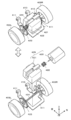
- FIG. 11 is a perspective view of the rear block 400 with the lid portion 405 removed, looking down from the upper left rear obliquely.
- FIG. 12 is a perspective view in which the block main body 402 is further omitted from FIG. 11 and the layout of the components of the drive system and the electric system mounted on the rear block 400 is clarified.
- a motor portion 428 and a gear portion 429 are mounted as drive system components. That is, the rear block 400 functions as a drive block.
- the motor unit 428 is configured by housing the motor 420 in the motor case 421. Then, depending on the housing position relationship of the motor case 421 with respect to the block main body 402, the motor 420 is housed in the rear block 400 so that the rotation shaft of the motor 420 is parallel to the rear wheel shaft 404.
- the gear unit 429 includes a pinion gear 422 and a reduction gear 423.
- a pinion gear 422 is mounted on the rotation shaft of the motor 420, and is engaged with a reduction gear 423 which is taken out from an insertion hole of the motor case 421 and press-fitted to the rear wheel shaft 404 so as to be inserted and removed.
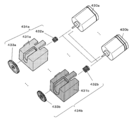
- FIG. 13 is a diagram illustrating a configuration example of a drive system replacement part (tune-up part).
- the sales package of the assembly type model 3 includes at least one motor 420, a motor case 421, a pinion gear 422, and a reduction gear 423. By using them, a drive system for one unit is assembled. It can be done.
- a plurality of types of tune-up motors 430 (430a, 430b,...) Having different outputs are separately prepared, and the user can select the motor 430 for the tune-up desired by the user. (430a, 430b,).
- the external dimensions of the tune-up motor 430 are the same in this embodiment.
- tune-up sets 434 (434a, 434b,...) are also separately prepared.
- One tune-up set 434 includes a tune-up pinion gear 432 (432a, 432b,%) And a tune-up reduction gear 433 (433a, 433b,%) That realize different gear ratios for each type, a dedicated motor case 431, Is included.
- the user 1) replaces the pinion gear 422 and the reduction gear 423 enclosed in the package with the tune-up pinion gear 432 and the tune-up reduction gear 433 included in the tune-up set 434, and 2) sets the motor case 421 enclosed in the package together.
- a gear ratio different from that of the package can be realized by replacing the dedicated motor case 431.
- the gear ratio can be changed, and the rotational speed and torque at which the power of the motor unit is output can be changed as appropriate.
- the dedicated motor case 431 functions as a spacer between the motor 420 and the inner space of the rear block 400 whose inner dimensions are determined.
- the internal dimensions of the dedicated motor case 431 are different for each type, and the position at which the motor 420 (or the tune-up motor 430) is held varies depending on the type. Then, the position is adjusted so that the tune-up pinion gear 432 and the tune-up reduction gear 433 included in the same tune-up set 434 are properly meshed with each other, in other words, the rotational axis of the motor 420 (or the tune-up motor 430).
- the distance between the rear wheel shaft 404 and the rear wheel shaft 404 is set appropriately.
- the tune-up pinion gear 432, the tune-up reduction gear 433, and the dedicated motor case 431 included in the same tune-up set 434 are unified with colors unique to the set. It is designed to encourage use at the same time.
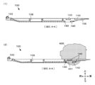
- FIG. 14 is a three-side view of the basic block 100, (1) a top view, (2) a left side view of the block, and (3) a bottom view.
- FIG. 15 is a cross-sectional view of the basic block 100 taken along the line AA, showing only (1) the cross-sectional view, and (2) the cross-sectional view with the relative positional relationship with the rear block 400 added.
- 1st rail 101 is extended in the right-and-left both sides of foundation block 100.
- a step 102 is provided at the front end of the first rail 101.
- Hook hook 103 is provided at the front end of base block 100, and is used when fixing cover 5 (see FIG. 1).
- a switch operation window 106 is opened at the center of the base block 100. Further, a rear rail guide 140 and a retaining fitting groove 105 are provided at the rear portion of the foundation block 100.
- FIG. 16 is a cross-sectional view taken along the line BB of the basic block 100, (1) only the cross-sectional view (2) is a view in which the relative positional relationship with the center block 300 is added to the cross-sectional view.
- the switch lever 310 (see FIG. 7) can be operated through the switch operation window 106.
- FIG. 17 is a cross-sectional view of the basic block 100 taken along the line CC, (1) only the cross-sectional view (2) is a view in which the relative positional relationship with the rear block 400 is added to the cross-sectional view.
- the rear rail guide 140 covers a guide extending piece 142 extending from both left and right sides and a lower side of the center notch 141 toward a center notch 141 provided from the rear substantially at the center of the left and right of the foundation block 100.
- Rail support plate part 143 passed to the left and right.
- the root portion of the second rail 401 (see FIGS. 4 and 10) is inserted into the central notch 141, and the left and right extended pieces (T-shaped Is equivalent to the arm portion) between the guide extension piece 142 and the rail support plate portion 143.
- the second rail 401 is abutted against the front end portion of the central notch 141 to determine the assembly position.
- claw hooks 409 that engage with the engaging claws 309 (see FIG. 7) of the center block 300 are provided on the left and right sides of the rear block 400 closer to the front.
- the engaging claw portion 309 engages with the claw hook portion 409, and both blocks can be fixed. Since the center block 300 and the rear block 400 need to be electrically connected, they are engaged for secure fixation.
- FIG. 18 is a view showing a configuration example of the retaining block 500, which is (1) a top view, (2) a front view, and (3) a DD sectional view.
- a retaining fitting protrusion 501 extends upward.
- a keyhole 503 is opened in the front-rear direction. The keyhole 503 is used when the cover 5 is attached to the vehicle body portion 7.
- a fitting recess 504 into which the rear end portion of the foundation block 100 is fitted is provided on the upper front surface of the retaining block 500.
- a tool hole 502 that opens upward is provided at the base.
- the tool hole 502 is used to make the retaining block 500 function as an assembly tool when assembling parts included in the sales package of the assembly model 3. Specifically, for example, as shown in FIG. 19, when one end of the rear wheel shaft 404 as a pivot is press-fitted and fixed to a wheel (represented by the left rear wheel 403L in FIG. 19), the other end of the rear wheel shaft 404 is fixed. Is inserted into the tool hole 502 to function as a pressing tool for press-fitting operation. The same applies to the press-fitting of the front wheel shaft 204 to the front wheels.
- the tool hole 502 may be provided in a connecting block other than the retaining block 500. In this way, since the parts constituting the assembly model also serve as tools, the number of separately prepared tools can be reduced.
- FIG. 20 is a transition diagram of the assembly state for explaining the assembly procedure of the vehicle body portion 7 and transitions from the top to the bottom of the diagram.
- FIG. 21 is a diagram for explaining a procedure for attaching the cover 5 to the vehicle body portion 7 that has been assembled. It is assumed that the user has assembled the front block 200, the center block 300, and the rear block 400 in advance.
- the fitting dimension between the first rail 101 and the front rail guide 201 is appropriately set so as to generate an appropriate slide resistance. This gives the user a sense of assembly. Then, it can be seen that the front block 200 has been properly assembled with the feeling that it hits the step 102.
- the fitting dimension between the first rail 101 and the center rail guide 301 is appropriately set so as to generate an appropriate slide resistance. This gives the user a sense of assembly.
- the rear end portion of the front block 200 and the front end portion of the center block 300 have a structure that is compatible with each other, the user feels that the center block 300 hits the front block 200 and that both blocks are It is possible to determine whether or not the assembly has been properly performed by visually observing the fitting. Specifically, when the center block 300 is correctly abutted after the front block 200, the fitting concave portion 205 and the fitting convex portion 305 are fitted, so that both blocks are mounted on the base block 100 in a predetermined connection order. That is, it can be seen that adjacent connected blocks are matched. If the front block 200 or the center block 300 is mistakenly assembled to the basic block 100, a gap that is clearly inadequate is generated between the two, so that the user can visually recognize that the assembly is wrong.
- the fitting dimension of the second rail 401 and the rear rail guide 140 is appropriately set so as to generate an appropriate slide resistance. This gives the user a sense of assembly.
- the rear end portion of the center block 300 and the front end portion of the rear block 400 have a structure that is compatible with each other, the user feels that the rear block 400 hits the center block 300 and that both blocks are By visually observing the conformity, it can be immediately judged whether the assembly has been properly performed. Specifically, when the rear block 400 is correctly abutted after the center block 300, 1) the engaging claw portion 309 engages with the claw hook portion 409, and 2) the conductive plates 410 and 411 are exposed from the cutout window 307. The center block 300 and the rear block 400 are attached to the base block in a predetermined connection order from the three points of contact with the end surface of the battery 8 to be engaged and 3) the fitting protrusion 406 to be fitted into the fitting recess 308.
- fitting dimension between the retaining fitting protrusion 501 and the fitting groove 412 is appropriately set so as to generate an appropriate slide resistance. This gives the user a sense of assembly.
- the stopper fitting protrusion 501 is inserted until it hits the upper end of the fitting groove 412, and the rear end portion of the foundation block 100 is the fitting recess 504 of the stopper block 500 (see FIG. 18).
- adjacent connecting blocks in which the rear block 400 and the retaining block 500 are mounted on the foundation block 100 are matched in a predetermined connecting order.
- the vehicle body portion 7 is completed.
- connection block can be removed from the basic block 100 by using the reverse procedure. That is, the connecting block is detachable from the basic block 100.
- the distal end shape of the locking body 9 is set so as to match the groove provided on the upper surface of the locking portion 304 of the lid portion 303 of the center block 300, and a second key (a tool for locking and unlocking). ).
- a second key a tool for locking and unlocking.
- a plurality of connecting blocks (front block 200, center block 300, rear block 400) are attached to the base block 100 by sliding them in a predetermined sliding direction (vehicle body longitudinal direction). Can do. Therefore, the rigidity of the assembly type model 3 can be increased as compared with the prior art.
- the connecting block is connected by the foundation block 100 so as to penetrate in the sliding direction, even if the connecting block is caused to run and collide with a course wall surface or another model, the connecting block is lifted. There is nothing, and the rigidity does not decrease. Moreover, since the connecting block at the end can be connected and fixed in the direction intersecting the sliding direction by the retaining block 500 together with the base block 100, the rigidity can be maintained high.
- connection blocks when the connection blocks are mounted on the basic block 100 in the correct connection order, the adjacent connection blocks have shapes that fit with each other. Can be prevented from being assembled by mistake. In addition, the displacement between the connecting blocks is suppressed, contributing to the maintenance of rigidity.
- a front block 200F that pivots two wheels on each of the left and right sides, and a center block 300S of a type that mounts a smaller battery are separately prepared. If these are replaced with the above-described front block 200 and center block 300, the vehicle model can be changed from a four-wheeled vehicle to a six-wheeled vehicle. In this configuration, it is necessary to replace the cover 5 for a six-wheeled vehicle, but the basic block 100, the rear block 400, and the retaining block 500 can be used as they are.
- the wheel base is modified. Will also be possible.
- the cover 5 also needs to be replaced for the long wheel base, but the front block 200, the center block 300, the rear block 400, and the retaining block 500 can be used as they are.
- the spacer block 600 shall be equipped with the fitting convex part 305 (refer FIG. 7) on the front surface, and shall be equipped with the fitting recessed part 205 (refer FIG. 6) on the rear surface.
- a center block 300S of a type that mounts a smaller battery and a rear block 400L of a differential gear mounted type that has a larger front-rear length are prepared separately, for example, during turning Remodeling to improve traction can be done easily.
- a retaining block 500J provided with a male joint 570 on the rear side and a base block 100J provided with a female joint 170 connected to the male joint 570 are separately prepared, two units are provided. It is also possible to convert the assembled model 3 into a single connected vehicle.
- Such a modification of the connecting block unit can be realized by adopting a configuration in which a plurality of connecting blocks are connected so as to penetrate in one sliding direction by the basic block 100 as in the present embodiment.
- the embodiment of the present invention is not limited to the above, and components can be added, changed, or omitted as appropriate.
- a structure that prevents the erroneous assembly of the center block 300 being erroneously mounted before the front block 200 may be added as appropriate in combination with the positioning of the assembly position of the center block 300.
- the first rail 101 engages with the front rail guide 201 of the front block 200 and the portion engages with the center rail guide 301 of the center block 300. It is sufficient to make the latter rail thickness W2 smaller than the former rail thickness W1.
- a four-wheel race car is exemplified as a design example of the assembly model 3, but other types of moving bodies may be used.
- a foundation corresponding to the connecting block (the foundation block 100, the front block 200, the center block 300, the rear block 400, and the retaining block 500) of the above-described embodiment such as an assembly model 3P shown in FIG.
- An airplane including a block 100p, a front block 200p, a center block 300p, a rear block 400p, and a retaining block 500p may be used.
- the drive system is mounted on the center block 300p and the battery is mounted on the rear block 400p.
- gear unit is configured by two gears, that is, a pinion gear and a reduction gear, has been described, but the type and number of the configured gears can be changed as appropriate.
- the cover 5 is finally assembled.
- the cover 5 is unnecessary, and it is of course possible to complete the assembly model 3 by assembling the vehicle body portion 7.
- the assembling model 3 is described as a moving body model, but it is not necessary to be a moving body.
- a model such as a robot may be used. In that case, it is good also as assembling an arm and a leg instead of a wheel, for example.
- mount and drive other electric parts such as a light or a sound instead of the motor 420.
Landscapes
- Toys (AREA)
Abstract
【課題】全く新しい組立型模型を実現する技術を提供すること。 【解決手段】組立型模型3の車体部7は、車体前後方向に長い基礎ブロック100で、3つの連結ブロック(前輪を枢支するフロントブロック200、電池を搭載するセンターブロック300、後輪を枢支するともにモータを搭載するリアブロック400)を所定の連結順に貫いて連結させて構成される。そして、末端のリアブロック400は、基礎ブロック100とともに、基礎ブロック100の車体前後方向へ交差するように抜け止めブロック500が差し込まれて強固な連結が維持される。各連結ブロックの端部は、隣接する連結ブロック同士で適切な順番で組み付けたときに適合する形状を有しており、間違った組み付けを防ぐとともに、連結剛性の維持に寄与する。
Description
本発明は組立型模型に関する。
ユーザが組み立てて模型を完成させる組立型模型が知られている。例えば、特許文献1及び特許文献2には、左右の前輪を枢支する組立体と、左右の後輪を枢支するとともにモータを内蔵した組立体とを、車両の床面構造体に相当する車体対して上から差し込むようにして組み付け、車体に電池を装着して走らせて遊ぶ自動車の組立型模型が開示されている。こうした自動車の組立型模型は、主に専用コースで互いの車を走らせて簡単なレースをして遊ぶものであり、モータなどの一部構成部品を別売のチューンナップ部品と交換することで改造する楽しみも味わえるようになっている。
さて、実際の自動車に限らず、自動車の組立型模型であっても車体剛性はレースにおける車体運動性能を左右する重要な要素となる。しかし、特許文献1や特許文献2に代表される従来の構成では、車体に対して組立体を上から差し込む構成であったため、コース側面のガイド壁や他の組立型模型などとの衝突を繰り返すうちに、差し込みが緩くなり車体剛性が低下する場合があった。
本発明は、上述の事情を鑑みて考案されたものである。その目的とするところは、従来と異なる全く新しい組立型模型を実現する技術を提供することである。
本発明の組立型模型は、基礎ブロックにN個(N≧2)の連結ブロックを組み付けて構成される組立型模型であって、前記基礎ブロックは、所定のスライド方向に前記連結ブロックを順にスライドさせて係合させることで、前記連結ブロックを着脱可能とする構造を有し、前記連結ブロックは、予め定められた連結順に前記基礎ブロックに装着された場合に、隣接する前記連結ブロック同士が適合する形状を有する。
本発明の組立型模型において、前記N個の連結ブロックが前記基礎ブロックに装着された後に、前記連結ブロックの抜け止めのため、末端の前記連結ブロック及び前記基礎ブロックに嵌合する抜け止めブロック、を更に備えることが好ましい。
また、本発明の組立型模型において、前記抜け止めブロックが、前記末端の連結ブロック及び前記基礎ブロックを、前記スライド方向に交差する方向に貫くように組み付けられることで、装着された前記N個の連結ブロックの抜け止めとして機能することが好ましい。
また、本発明の組立型模型において、前記基礎ブロックに前記N個の連結ブロック及び前記抜け止めブロックが装着された状態の上に被せられるカバーと、前記カバーを前記抜け止めブロックに固定するための施錠体と、を更に備えることが好ましい。
また、本発明の組立型模型において、前記N個の連結ブロックには、電池を搭載する電池搭載用ブロック(例えば、図2のセンターブロック300)が含まれ、前記電池搭載用ブロックは、搭載した電池を覆う蓋部と、当該蓋部を施錠する施錠部とを有し、前記施錠体は、前記施錠部を施錠及び開錠するための工具を兼ねることが好ましい。
また、本発明の組立型模型において、前記N個の連結ブロックには、駆動軸、モータ部及びギア部を搭載する駆動用ブロック(例えば、図2のリアブロック400)が含まれ、前記駆動用ブロックは、前記駆動軸の配置位置を固定位置とし、前記モータ部を他の種類のモータ部に交換可能に有し、前記ギア部を、搭載された前記モータ部の駆動力を前記固定位置の前記駆動軸に伝達可能であり、且つ、搭載された前記モータ部に応じたギア比となる種類のギア部に交換可能に有することが好ましい。
また、本発明の組立型模型は、基礎ブロックに、駆動軸、モータ部及びギア部を搭載する駆動用ブロック(例えば、図2のリアブロック400)を含むN個(N≧2)の連結ブロックを組み付けて構成される組立型模型であって、前記駆動用ブロックは、前記駆動軸の配置位置を固定位置とし、前記モータ部を他の種類のモータ部に交換可能に有し、前記ギア部を、搭載された前記モータ部の駆動力を前記固定位置の前記駆動軸に伝達可能であり、且つ、搭載された前記モータ部に応じたギア比となる種類のギア部に交換可能に有する。
また、本発明の組立型模型において、前記ギア部が、搭載された前記モータ部の回転軸と前記駆動軸との軸間距離に応じた複数のギアの組み合わせで構成されることが好ましい。
また、本発明の組立型模型において、前記モータ部が、モータと、当該モータを収容する交換可能なケースとを有し、当該ケースが交換されることで、前記駆動軸に対する軸間距離が異なる別の種類のモータ部を構成することが好ましい。
また、本発明の組立型模型において、前記N個の連結ブロックには、前輪用の左右の車輪を枢支する前輪用ブロック(例えば、図2のフロントブロック200)と、後輪用の左右の車輪を枢支する後輪用ブロック(例えば、図2のリアブロック400)とが含まれ、移動体の模型であることが好ましい。
また、本発明の組立型模型において、前記N個の連結ブロックの何れかの連結ブロックは、前記車輪を枢軸(例えば、図19の後輪軸404)に固定させる際の工具を兼ねることが好ましい。
本発明によれば、全く新しい組立型模型を実現する技術を提供することができる。
図1は、本発明を適用した組立型模型の完成状態の外観例を示す斜視外観図である。
本実施形態の組立型模型3は、ユーザ自身が販売パッケージに含まれるパーツを組み立てて完成させる4輪車タイプの移動体の模型である。デザインの異なるカバー5(一体型のカウル)をパッケージ別に用意することで、同じ車格でも異なる車種を提供できるようになっている。
本実施形態の組立型模型3は、ユーザ自身が販売パッケージに含まれるパーツを組み立てて完成させる4輪車タイプの移動体の模型である。デザインの異なるカバー5(一体型のカウル)をパッケージ別に用意することで、同じ車格でも異なる車種を提供できるようになっている。
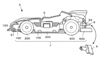
図2は、カバー5を取り去った状態の組立型模型3の上面図であって、カバー5に覆われていた車体部を示している。図3は、車体部を模型の正面向かって右側から見た側面図である。なお、これらの図の左上には構造を簡略化した略図を加えている。また、図4は、前方斜め下から見た車体部の分解図である。
図2~図4に示すように、組立型模型3の車体部7は、基礎ブロック100に複数個の連結ブロックを予め定められた連結順で組み付けや分解が可能に構成される。本実施形態の連結ブロックは、フロントブロック200と、センターブロック300と、リアブロック400と、抜け止めブロック500とである。
基礎ブロック100は、組立型模型3の進行方向(前後方向)に沿って長い薄板状の構造体であって、デザイン上は車両のフロントバンパーと車体床面構造体とを兼ねている。
フロントブロック200は、前輪となる左右の車輪203R,203Lを枢支する前輪用のブロックである。
センターブロック300は、電池8を搭載する電池搭載用ブロックである。
リアブロック400は、後輪となる左右の車輪403R,403Lを枢支するともに、モータ420等の駆動系部品を内蔵する後輪用のブロック兼駆動用ブロックである。
抜け止めブロック500は、基礎ブロック100及び、連結した際の末端ブロックであるリアブロック400に対して、車体前後方向と交差する方向から嵌合する部位であって、デザイン上は車両のリアバンパーを兼ねる。
フロントブロック200は、前輪となる左右の車輪203R,203Lを枢支する前輪用のブロックである。
センターブロック300は、電池8を搭載する電池搭載用ブロックである。
リアブロック400は、後輪となる左右の車輪403R,403Lを枢支するともに、モータ420等の駆動系部品を内蔵する後輪用のブロック兼駆動用ブロックである。
抜け止めブロック500は、基礎ブロック100及び、連結した際の末端ブロックであるリアブロック400に対して、車体前後方向と交差する方向から嵌合する部位であって、デザイン上は車両のリアバンパーを兼ねる。
図4に示すように、基礎ブロック100の左右側面には第1レール101が、車体前後方向に沿って延設されている。フロントブロック200と、センターブロック300には、それぞれ第1レール101とスライド自在に係合するフロントレールガイド201、センターレールガイド301が設けられている。また、リアブロック400の底面には比較的短めの第2レール401が突設されており、基礎ブロック100の後部には当該第2レール401とスライド自在に係合するリアレールガイド140が設けられている。
本実施形態の車体部7は、基礎ブロック100が一種の背骨・キールの役目を担い、フロントブロック200,センターブロック300,リアブロック400の3つの連結ブロックを車体前後方向(スライド方向)に沿ってスライド可能に一体に串刺しし、抜け止めブロック500で3つの連結ブロックが基礎ブロック100から抜けるのを止める構成を有している。
では、順に各ブロックの詳細について説明する。
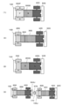
図5及び図6は、組立完了状態のフロントブロック200の斜視図であって、図5は模型の左前方斜め上から見た斜視外観図、図6は模型の左前方斜め下から見た斜視外観図である。
図5及び図6は、組立完了状態のフロントブロック200の斜視図であって、図5は模型の左前方斜め上から見た斜視外観図、図6は模型の左前方斜め下から見た斜視外観図である。
フロントブロック200は、上方に開口する箱状のブロック主体202に、左前輪203L及び右前輪203Rを前輪軸204(枢軸)で連結して枢支する。そして、ブロック主体202の下面(裏面)の左右辺縁部には、車体前後方向(スライド方向)に沿ったフロントレールガイド201が突設されている。
本実施形態のフロントレールガイド201は、左右一対で構成されている。当該ブロックにとっての右側に設けられたフロントレールガイド201を、正面から見ると、下方に延びた後に右側(内側)に屈曲した断面(正面視L字状とも言える)を有する。対して、当該ブロックにとっての左側のフロントレールガイド201は、下方に延びた後に左側(内側)に屈曲した断面(正面視左右反転したL字状とも言える)を有する。そして、これら左右1対のフロントレールガイド201は、それぞれ基礎ブロック100の第1レール101と適度な操作抵抗を生む程度にスライド自在に遊嵌するように寸法が決定されている。
なお、本実施形態では、組み付け後に基礎ブロック100の下面(底面)が見えるようにフロントレールガイド201を左右分割して構成しているが、左右のフロントレールガイド201を一体とし、フロントブロック200の下部を前後に貫通する貫通孔として実現してもよい。
また、ブロック主体202の後面には、車体部7の組立完了状態において後方に隣接するセンターブロック300の前部に適合する形状の嵌合凹部205が凹設されている。
図7は、センターブロック300の5面図であって、(1)前面図、(2)上面図、(3)後面図、(4)左側面図、(5)下面図(裏面図)である。図8は、センターブロック300をブロックの左後方斜め下より見上げた斜視外観図である。図9は、センターブロック300をブロックの左前方斜め下より見上げた斜視外観図である。
センターブロック300は、上方に開口した電池収容部302に、2本の電池8を収容し、収容した電池8の上方を蓋部303で覆って固定する電池搭載用ブロックである。蓋部303には施錠部304が設けられており施錠ができるようになっている。
電池収容部302には、収容した電池8の前端同士を接続させる接続端子を兼ねたスイッチ端子が内蔵されており(図示略)、電池収容部302の下面(底面・裏面)には、スイッチ端子をON/OFFするスイッチレバー310が突設されている。
センターブロック300の下面の左右辺縁部には、車体前後方向(スライド方向)に沿ってセンターレールガイド301が設けられている。本実施形態のセンターレールガイド301は左右一対で構成されている。
当該ブロックにとっての右側に設けられたセンターレールガイド301を、正面から見ると、下方に延びた後に右側に屈曲した断面(正面視L字状とも言える)を有する。対して、当該ブロックにとっての左側に設けられたセンターレールガイド301は、下方に延びた後に左側に屈曲した断面(正面視左右反転したL字状とも言える)を有する。そして、左右1対のセンターレールガイド301は、基礎ブロック100の第1レール101と適度な操作抵抗を生む程度にスライド自在に遊嵌するように寸法が決定されている。
当該ブロックにとっての右側に設けられたセンターレールガイド301を、正面から見ると、下方に延びた後に右側に屈曲した断面(正面視L字状とも言える)を有する。対して、当該ブロックにとっての左側に設けられたセンターレールガイド301は、下方に延びた後に左側に屈曲した断面(正面視左右反転したL字状とも言える)を有する。そして、左右1対のセンターレールガイド301は、基礎ブロック100の第1レール101と適度な操作抵抗を生む程度にスライド自在に遊嵌するように寸法が決定されている。
なお、本実施形態では、組み付け後に基礎ブロック100の下面が見えるようにセンターレールガイド301を左右分割して構成しているが、左右のセンターレールガイド301を一体とし、センターブロック300の下部を前後に貫通する貫通孔として実現してもよい。
また、センターブロック300の前面には、車体部7の組立完了状態において前方に隣接するフロントブロック200の後部に適合する形状の嵌合凸部305が凸設されている。
また、センターブロック300の後面には、収容された電池8の後方端面が露出するように切り欠き窓307と、車体部7の組立完了状態において後方に隣接するリアブロック400の前面形状に適合する形状の嵌合凹部308と、が設けられている。
更に、センターブロック300の後部左右側面には、車体部7の組立完了状態において後方に隣接するリアブロック400の左右側面と係合する係合爪部309がそれぞれ設けられている。
図10は、リアブロック400の構成例を示す5面図であって、(1)前面図、(2)上面図、(3)後面図、(4)左側面図、(5)下面図(裏面図)である。
リアブロック400は、上方に開口した箱状のブロック主体402に左後輪403L及び右後輪403Rを後輪軸404で連結して枢支するとともに、ブロック主体402の開口部を蓋部405で覆って画成した内部空間にモータ420等を含む駆動系を搭載する。つまり、本実施形態のリアブロック400は駆動系部品を搭載する駆動用ブロックと言い換えることができる。
リアブロック400は、上方に開口した箱状のブロック主体402に左後輪403L及び右後輪403Rを後輪軸404で連結して枢支するとともに、ブロック主体402の開口部を蓋部405で覆って画成した内部空間にモータ420等を含む駆動系を搭載する。つまり、本実施形態のリアブロック400は駆動系部品を搭載する駆動用ブロックと言い換えることができる。
リアブロック400の前面には、車体部7の組立完了状態において前方に隣接するセンターブロック300の後面の嵌合凹部308に適合する形状の嵌合突起406と、センターブロック300の後面から露出する電池8の端面に接触する一対の電導板410及び電導板411が設けられている。
電導板410及び電導板411は、リアブロック400の下面を伝うように固定され、リアブロック400の内部空間に導かれる。そして、内部空間に収容されているモータ420の電極に接触するように配置されている。
また、リアブロック400の下面には、第2レール401が突設されている。本実施形態の第2レール401は、車両前後方向に長く、リアブロック400の下面より下方に延びた後に左右にフランジ状に広がった正面視形状(正面視逆さT字とも言える)を有する。
また、リアブロック400の後面には、抜け止めブロック500を嵌合させる嵌合溝412が設けられている。
図11は、蓋部405を取り外した状態のリアブロック400を左後方斜め上から見下ろした斜視図である。図12は、図11から更にブロック主体402の図示を省略して、リアブロック400に搭載される駆動系及び電気系の構成部品のレイアウトを明らかにした斜視図である。
ブロック主体402と蓋部405とで画成される内部空間には、駆動系の構成部品としてモータ部428とギア部429とが搭載されている。すなわち、リアブロック400は駆動用ブロックとして機能する。
具体的には、モータ部428は、モータケース421にモータ420を収容して構成される。そして、ブロック主体402へのモータケース421の収容位置関係によって、モータ420の回転軸が後輪軸404と平行になるようにリアブロック400に収容される。
ギア部429は、ピニオンギア422と減速ギア423とで構成される。モータ420の回転軸にはピニオンギア422が装着されておりモータケース421の挿通孔より外に出され、後輪軸404に抜き差し可能に圧入された減速ギア423と噛み合わされている。
図13は、駆動系の交換パーツ(チューンナップ用パーツ)の構成例を示す図である。
組立型模型3の販売パッケージには、モータ420と、モータケース421と、ピニオンギア422と、減速ギア423とが少なくとも1つずつ入っており、それらを使うことで1台分の駆動系を組立できるようになっている。
組立型模型3の販売パッケージには、モータ420と、モータケース421と、ピニオンギア422と、減速ギア423とが少なくとも1つずつ入っており、それらを使うことで1台分の駆動系を組立できるようになっている。
そして、パッケージ同封のそれらとは別に、出力が異なる複数種類のチューンナップ用モータ430(430a,430b,…)が別途用意されており、ユーザはパッケージ同封のモータ420を、好みのチューンナップ用のモータ430(430a,430b,…)に交換することができる。チューンナップ用モータ430の外形寸法は本実施形態では同じこととする。
また、複数種類のチューンナップセット434(434a,434b,…)も別途用意されている。1つのチューンナップセット434には、種類毎に異なるギア比を実現するチューンナップ用ピニオンギア432(432a,432b,…)及びチューンナップ用減速ギア433(433a,433b,…)と、専用モータケース431と、が含まれる。
ユーザは、1)パッケージ同封のピニオンギア422及び減速ギア423を、チューンナップセット434に含まれていたチューンナップ用ピニオンギア432及びチューンナップ用減速ギア433に組み替え、2)パッケージ同封のモータケース421を同セットの専用モータケース431に交換する、ことでパッケージとは異なるギア比を実現することができる。このようにパーツを変更することでギア比を変更し、モータ部の動力をどのような回転数やトルクで出力させるかを適宜変更できるようになる。
専用モータケース431は、内寸が決まっているリアブロック400の内部空間とモータ420との間のスペーサとして機能する。専用モータケース431は、その種類毎に内部寸法が異なっており、モータ420(或いはチューンナップ用モータ430)をその内部に保持する位置が種類によって異なる。そして、その位置は、同じチューンナップセット434に含まれるチューンナップ用ピニオンギア432とチューンナップ用減速ギア433とが適切に噛み合わされるように、換言すると、モータ420(或いはチューンナップ用モータ430)の回転軸と後輪軸404との軸間距離を適切に保つように設定されている。
モータ420(或いはチューンナップ用モータ430)の交換やギア比の変更にともない、モータ420が収容されている位置が変化しても、電導板410,411のモータ側端部の上下方向及び前後方向の幅が十分確保されることにより電気的な接続関係は安定して確保される。
なお、間違った組み合わせで使用されることを防ぐために、同じチューンナップセット434に含まれるチューンナップ用ピニオンギア432と、チューンナップ用減速ギア433と、専用モータケース431とは、セット固有の色で統一されており、同時に使用されることを促すようになっている。
本実施の形態に示す組立型模型によると、ギア比の変更にともないモータの回転軸と駆動軸との軸間距離が変わるとしても、モータとケースとをセットにして交換するだけで簡単に対応することができる。軸間距離が変わっても簡単に対処できるということは、軸間距離に限定されない様々な改造が可能になることを意味し、改造する楽しみを増すことに繋がる。
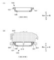
図14は、基礎ブロック100の3面図であって、(1)上面図、(2)ブロックの左側面図、(3)下面図である。図15は、基礎ブロック100のA-A断面図であって、(1)断面図のみ、(2)断面図にリアブロック400との相対位置関係を追加した図、である。
基礎ブロック100の左右両側部には、第1レール101が延設されている。第1レール101の前端部には段差102が設けられている。フロントブロック200を基礎ブロック100に組み付けた際に、フロントブロック200の前端部が段差102に突き当てられることで、基礎ブロック100とフロントブロック200との相対位置が決められるように構成されている。
基礎ブロック100の前端部にはフック掛け103が設けられており、カバー5(図1参照)を固定する際に使用される。基礎ブロック100の中央にはスイッチ操作窓106が開けられている。また、基礎ブロック100の後部には、リアレールガイド140と、抜け止め嵌合溝105と、が設けられている。
図16は、基礎ブロック100のB-B断面図であって、(1)断面図のみ(2)断面図にセンターブロック300との相対位置関係を追記した図、である。
基礎ブロック100にセンターブロック300を組み付けると、スイッチ操作窓106を通じてスイッチレバー310(図7参照)が操作できるようになる。
基礎ブロック100にセンターブロック300を組み付けると、スイッチ操作窓106を通じてスイッチレバー310(図7参照)が操作できるようになる。
図17は、基礎ブロック100のC-C断面図であって、(1)断面図のみ(2)断面図にリアブロック400との相対位置関係を追記した図、である。
リアレールガイド140は、基礎ブロック100の左右略中央に後方より設けられた中央切り欠き141に向かって、左右両側から延設されたガイド延設片142と、中央切り欠き141の下側を覆うように左右に渡されたレール支持板部143とを有する。
リアレールガイド140は、基礎ブロック100の左右略中央に後方より設けられた中央切り欠き141に向かって、左右両側から延設されたガイド延設片142と、中央切り欠き141の下側を覆うように左右に渡されたレール支持板部143とを有する。
基礎ブロック100にリアブロック400を後方から組み付ける際、第2レール401(図4,図10参照)の根元部分が中央切り欠き141に挿通され、第2レール401の左右延設片(T字の腕の部分に相当)が、ガイド延設片142とレール支持板部143との間で案内される。なお、第2レール401は中央切り欠き141の前端部に突き当てられることで組付け位置が決められる。
図10に戻って、リアブロック400の前方寄り左右側面には、それぞれセンターブロック300の係合爪部309(図7参照)と係合する爪掛け部409が設けられている。センターブロック300の後にリアブロック400を正しく突き当てると、係合爪部309が爪掛け部409と係合し、両ブロックを固定させることができる。センターブロック300とリアブロック400とは電気的な接続が必要となることから、確実な固定のために係合させるのである。
図18は、抜け止めブロック500の構成例を示す図であって、(1)上面図、(2)前面図、(3)D-D断面図、である。
抜け止めブロック500の前端部には、上方へ向けて抜け止め嵌合突起501が延設されている。その上部には、前後方向に鍵穴503が開口している。この鍵穴503は車体部7にカバー5を取り付ける際に使用される。
抜け止めブロック500の前端部には、上方へ向けて抜け止め嵌合突起501が延設されている。その上部には、前後方向に鍵穴503が開口している。この鍵穴503は車体部7にカバー5を取り付ける際に使用される。
また、抜け止めブロック500の前寄り上面には、基礎ブロック100の後端部が嵌着される嵌着凹部504が凹設されている。
また、その根元には上方に向けて開口する工具孔502が設けられている。工具孔502は、組立型模型3の販売パッケージに含まれるパーツの組立の際に、抜け止めブロック500を組立工具として機能させるために使用される。具体的には、例えば図19に示すように、車輪(図19では代表して左後輪403Lを表記)に枢軸である後輪軸404の一端を圧入固定する際に、後輪軸404の他端を工具孔502に入れて圧入動作の押し込み工具として機能させる。同様のことは、前輪に対する前輪軸204の圧入についても同様である。
なお、工具孔502は、抜け止めブロック500以外の連結ブロックに設ける構成としてもよい。このように組立型模型を構成するパーツが工具も兼ねることにより、別途用意する工具の数を減らすことができる。
なお、工具孔502は、抜け止めブロック500以外の連結ブロックに設ける構成としてもよい。このように組立型模型を構成するパーツが工具も兼ねることにより、別途用意する工具の数を減らすことができる。
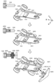
次に、図20~図21を参照しながら組立型模型3の組立手順について説明する。
図20は、車体部7の組立手順を説明するための組立状態の遷移図であって、図の上から下へ遷移する。図21は、組立完了した車体部7にカバー5を取り付ける手順を説明するための図である。なお、ユーザは、予めフロントブロック200と、センターブロック300と、リアブロック400とを組立済であるものとする。
図20は、車体部7の組立手順を説明するための組立状態の遷移図であって、図の上から下へ遷移する。図21は、組立完了した車体部7にカバー5を取り付ける手順を説明するための図である。なお、ユーザは、予めフロントブロック200と、センターブロック300と、リアブロック400とを組立済であるものとする。
手順[1]
基礎ブロック100の後端部を、フロントブロック200の前方よりアプローチさせ、その底面に沿ってフロントレールガイド201へ差し込むようにして両者を組み付ける。車体前後方向(スライド方向)に沿ってスライドさせるのである。この際、基礎ブロック100の第1レール101がフロントブロック200のフロントレールガイド201と摺接し、第1レール101に沿ってスライドさせるようにしてフロントブロック200が組み付けられる(図20の上段の状態に相当)。
基礎ブロック100の後端部を、フロントブロック200の前方よりアプローチさせ、その底面に沿ってフロントレールガイド201へ差し込むようにして両者を組み付ける。車体前後方向(スライド方向)に沿ってスライドさせるのである。この際、基礎ブロック100の第1レール101がフロントブロック200のフロントレールガイド201と摺接し、第1レール101に沿ってスライドさせるようにしてフロントブロック200が組み付けられる(図20の上段の状態に相当)。
なお、第1レール101とフロントレールガイド201との嵌め合い寸法は適度なスライド抵抗を生むように適宜設定される。これにより、ユーザに組み立てている実感を抱かせる。そして、フロントブロック200が段差102に突き当たる感触で、適切に組み付けられたことが分かるようになっている。
手順[2]
フロントブロック200が組み付けられた状態の基礎ブロック100の後端部を、センターブロック300の前方よりアプローチさせ、その底面に沿ってセンターレールガイド301へ差し込むようにして両者を組み付ける。車体前後方向(スライド方向)に沿ってスライドさせるのである。この際、基礎ブロック100の第1レール101がセンターレールガイド301と摺接し、第1レール101に沿ってスライドさせるようにしてセンターブロック300が組み付けられる(図20の中段の状態に相当)。
フロントブロック200が組み付けられた状態の基礎ブロック100の後端部を、センターブロック300の前方よりアプローチさせ、その底面に沿ってセンターレールガイド301へ差し込むようにして両者を組み付ける。車体前後方向(スライド方向)に沿ってスライドさせるのである。この際、基礎ブロック100の第1レール101がセンターレールガイド301と摺接し、第1レール101に沿ってスライドさせるようにしてセンターブロック300が組み付けられる(図20の中段の状態に相当)。
なお、第1レール101とセンターレールガイド301との嵌め合い寸法は適度なスライド抵抗を生むように適宜設定される。これにより、ユーザに組み立てている実感を抱かせる。
また、フロントブロック200の後端部と、センターブロック300の前端部とは、相互に適合する構造を有しているので、ユーザは、センターブロック300がフロントブロック200に突き当たる感触と、両ブロックが嵌合していることを目視することとで、適切に組み付けできたかを判断できる。
具体的には、フロントブロック200の後にセンターブロック300を正しく突き当てると嵌合凹部205と嵌合凸部305とが適合することで、予め定められた連結順に両ブロックが基礎ブロック100に装着された、すなわち隣接する連結ブロック同士が適合したことが分かる。もし、フロントブロック200或いはセンターブロック300の前後を間違えて基礎ブロック100へ組み付けた場合、両者の間に明らかに不適合な隙間が生じるためユーザは間違った組み付けをしたことが視覚的に直ぐに分かる。
具体的には、フロントブロック200の後にセンターブロック300を正しく突き当てると嵌合凹部205と嵌合凸部305とが適合することで、予め定められた連結順に両ブロックが基礎ブロック100に装着された、すなわち隣接する連結ブロック同士が適合したことが分かる。もし、フロントブロック200或いはセンターブロック300の前後を間違えて基礎ブロック100へ組み付けた場合、両者の間に明らかに不適合な隙間が生じるためユーザは間違った組み付けをしたことが視覚的に直ぐに分かる。
手順[3]
フロントブロック200とセンターブロック300とが組み付けられた状態の基礎ブロック100の後端部を、リアブロック400の前方よりアプローチさせ、第2レール401を、リアレールガイド140に迎え入れるようにして差し込んで組み付ける。車体前後方向(スライド方向)に沿ってスライドさせるのである。この際、リアブロック400の第2レール401がリアレールガイド140と摺接し、第2レール401に沿ってスライドさせるようにしてリアブロック400が組み付けられる(図20の下段の状態に相当)。
フロントブロック200とセンターブロック300とが組み付けられた状態の基礎ブロック100の後端部を、リアブロック400の前方よりアプローチさせ、第2レール401を、リアレールガイド140に迎え入れるようにして差し込んで組み付ける。車体前後方向(スライド方向)に沿ってスライドさせるのである。この際、リアブロック400の第2レール401がリアレールガイド140と摺接し、第2レール401に沿ってスライドさせるようにしてリアブロック400が組み付けられる(図20の下段の状態に相当)。
なお、第2レール401とリアレールガイド140との嵌め合い寸法は適度なスライド抵抗を生むように適宜設定される。これにより、ユーザに組み立てている実感を抱かせる。
また、センターブロック300の後端部と、リアブロック400の前端部とは、相互に適合する構造を有しているので、ユーザは、リアブロック400がセンターブロック300に突き当たる感触と、両ブロックが適合していることを目視することとで、適切に組み付けできたかを直ぐに判断できる。
具体的には、センターブロック300の後にリアブロック400を正しく突き当てると、1)係合爪部309が爪掛け部409と係合し、2)電導板410,411が切り欠き窓307から露出する電池8の端面に接触する、3)嵌合凹部308に嵌合突起406が嵌合する、の3点から、予め定められた連結順にセンターブロック300とリアブロック400とが基礎ブロックに装着され、隣接する連結ブロック同士が適合したことが分かる。もし、リアブロック400の前後を間違えて基礎ブロック100へ組み付けた場合、電池8の後端部に電導板410,411が接触せず、両者の間に明らかに不適合な隙間が生じるためユーザは間違った組み付けをしたことが視覚的に直ぐに分かる。
具体的には、センターブロック300の後にリアブロック400を正しく突き当てると、1)係合爪部309が爪掛け部409と係合し、2)電導板410,411が切り欠き窓307から露出する電池8の端面に接触する、3)嵌合凹部308に嵌合突起406が嵌合する、の3点から、予め定められた連結順にセンターブロック300とリアブロック400とが基礎ブロックに装着され、隣接する連結ブロック同士が適合したことが分かる。もし、リアブロック400の前後を間違えて基礎ブロック100へ組み付けた場合、電池8の後端部に電導板410,411が接触せず、両者の間に明らかに不適合な隙間が生じるためユーザは間違った組み付けをしたことが視覚的に直ぐに分かる。
手順[4]
基礎ブロック100へフロントブロック200とセンターブロック300とリアブロック400とを順に組み付けると、リアブロック400の嵌合溝412(図10参照)と、基礎ブロック100の抜け止め嵌合溝105(図14参照)との溝とが上下方向に一致する。ユーザは、ここに抜け止め嵌合突起501を差し込む様にして、抜け止めブロック500を基礎ブロック100及びリアブロック400に組み付ける。具体的には、抜け止めブロック500を、車体前後方向(スライド方向)と交差する方向、本実施形態では車体上下方向に、車体下面側から上に向けて抜け止め嵌合突起501を差し込む。
基礎ブロック100へフロントブロック200とセンターブロック300とリアブロック400とを順に組み付けると、リアブロック400の嵌合溝412(図10参照)と、基礎ブロック100の抜け止め嵌合溝105(図14参照)との溝とが上下方向に一致する。ユーザは、ここに抜け止め嵌合突起501を差し込む様にして、抜け止めブロック500を基礎ブロック100及びリアブロック400に組み付ける。具体的には、抜け止めブロック500を、車体前後方向(スライド方向)と交差する方向、本実施形態では車体上下方向に、車体下面側から上に向けて抜け止め嵌合突起501を差し込む。
なお、抜け止め嵌合突起501と嵌合溝412との嵌め合い寸法は適度なスライド抵抗を生むように適宜設定される。これにより、ユーザに組み立てている実感を抱かせる。
ユーザは、抜け止め嵌合突起501を嵌合溝412の上端部に突き当てるまで差し込んだ突き当て感と、基礎ブロック100の後端部が抜け止めブロック500の嵌着凹部504(図18参照)に嵌入した状態を目視することとで、予め定められた連結順にリアブロック400と抜け止めブロック500とが基礎ブロック100に装着された、隣接する連結ブロック同士が適合したことが分かる。これで、車体部7が完成したことになる。
なお、装着の手順を順を追って説明しているが、逆順の手順とすることで、連結ブロックを基礎ブロック100から取り外すことができる。すなわち、連結ブロックは基礎ブロック100に対して着脱自在である。
手順[5]
車体部7の組立が完了したならば、車体部7にカバー5を被せて、施錠体9で両者を固定する(図21の状態に相当)。
具体的には、カバー5の前方下端のフック51を、基礎ブロック100のフック掛け103(図14参照)に掛け、ここを支点にしながらカバー5を車体部7に被せる。すると、カバー5の後端部の鍵穴53が、抜け止め嵌合突起501の鍵穴503(図18参照)と穴位置が合わさり施錠体9の受け入れが可能になる。ユーザは、施錠体9を鍵穴53及び鍵穴503に差し込んで捻ることで、車体部7にカバー5を固定する。
車体部7の組立が完了したならば、車体部7にカバー5を被せて、施錠体9で両者を固定する(図21の状態に相当)。
具体的には、カバー5の前方下端のフック51を、基礎ブロック100のフック掛け103(図14参照)に掛け、ここを支点にしながらカバー5を車体部7に被せる。すると、カバー5の後端部の鍵穴53が、抜け止め嵌合突起501の鍵穴503(図18参照)と穴位置が合わさり施錠体9の受け入れが可能になる。ユーザは、施錠体9を鍵穴53及び鍵穴503に差し込んで捻ることで、車体部7にカバー5を固定する。
なお、施錠体9の先端形状は、センターブロック300の蓋部303の施錠部304の上面に設けられた溝部と適合するように設定されており第2の鍵(施錠や解錠のための工具)としても機能する。このように施錠体に複数の役割を与えることにより、部品点数を削減することができる。もし、施錠部用の工具を別途用意する構成では、当該工具を忘れると現場で電池交換できなくなるが、施錠体が当該工具を兼ねしかも完成した模型と一体となるため、そうした事態を避けることができる。
以上、本実施形態によれば、基礎ブロック100に対して複数の連結ブロック(フロントブロック200,センターブロック300,リアブロック400)を所定のスライド方向(車体前後方向)にスライドさせることで装着させることができる。よって、組立型模型3の剛性を従来より高めることができる。
すなわち、従来の構成のように、車体に対してパーツを上から差し込む構成であれば、組立型模型を走行させてコース壁面や他の模型などと衝突を繰り返すうちに衝突の衝撃でパーツが浮き上がりかねず、ついには剛性が低下してしまうおそれがある。
しかし、本実施形態の構成では、連結ブロックが基礎ブロック100によってスライド方向に貫かれるように連結されているので、走行させてコース壁面や他の模型と衝突させたとしても、連結ブロックが浮き上がるようなことはなく、剛性が低下することはない。しかも、末端の連結ブロックを基礎ブロック100とともに抜け止めブロック500で、スライド方向と交差する方向に連結・固定することができるので、剛性を高く維持することができる。
また、本実施形態によれば、連結ブロックが正しい連結順に基礎ブロック100に装着された場合には、隣接する連結ブロック同士が適合する形状を有しているので、連結ブロックの連結順や連結方向を間違って組み付けることを防止できる。加えて、連結ブロック同士のズレを抑制し剛性の維持に寄与する。
また、本実施形態によれば、連結ブロック単位で様々な種類を用意することで、駆動力やギア比といったチューンナップに加えて、外観から明らかな車格や車種の改造を簡単にできるようになる。
例えば、図22(1)に示すように、左右それぞれで2輪ずつ枢支するフロントブロック200Fと、より小型の電池を搭載するタイプのセンターブロック300Sと、を別途用意する。そして、これらと上述のフロントブロック200及びセンターブロック300と交換すれば、4輪車から6輪車に車両モデルを変更することができる。当該構成では、カバー5も6輪車用に交換する必要があるが、基礎ブロック100とリアブロック400と抜け止めブロック500はそのまま使える。
また、図22(2)に示すように、上述の基礎ブロック100より長尺の基礎ブロック100Bと、フロントブロック200とセンターブロック300との間のスペーサブロック600とを用意すればホイルベースを変更する改造も可能になる。当該構成では、カバー5もロングホイルベース用に交換する必要があるが、フロントブロック200と、センターブロック300と、リアブロック400と、抜け止めブロック500とはそのまま使える。なお、スペーサブロック600は、前面に嵌合凸部305(図7参照)を備え、後面に嵌合凹部205(図6参照)を備えるものとする。
また、図22(3)に示すように、より小型の電池を搭載するタイプのセンターブロック300Sと、より前後長が大きいデファレンシャルギア搭載タイプのリアブロック400Lとを別途用意すれば、例えば旋回時のトラクションを向上する改造も簡単にできるようになる。
更に、図22(4)に示すように、後方にオスジョイント570を備えた抜け止めブロック500Jと、オスジョイント570と連結するメスジョイント170を備えた基礎ブロック100Jとを別途用意すれば、2台の組立型模型3から1台の連結型車両に改造することも可能になる。
こうした連結ブロック単位の改造は、本実施形態のように基礎ブロック100で複数の連結ブロックを1つのスライド方向に貫くようにして連結する構成を採用することにより実現できる。
〔変形例〕
なお、本発明の実施形態は上記に限るものではなく、適宜構成要素の追加・変更・省略ができる。
例えば、センターブロック300の組付け位置の位置決めを兼ねて、センターブロック300を誤ってフロントブロック200よりも先に装着してしまう誤組み付けを防止する構造を適宜追加してもよい。具体的には、図23に示す基礎ブロック100Bのように、第1レール101を、フロントブロック200のフロントレールガイド201と係合する部分と、センターブロック300のセンターレールガイド301と係合する部分とに分け、前者のレール厚みW1よりも後者のレール厚みW2を小さくすればよい。
なお、本発明の実施形態は上記に限るものではなく、適宜構成要素の追加・変更・省略ができる。
例えば、センターブロック300の組付け位置の位置決めを兼ねて、センターブロック300を誤ってフロントブロック200よりも先に装着してしまう誤組み付けを防止する構造を適宜追加してもよい。具体的には、図23に示す基礎ブロック100Bのように、第1レール101を、フロントブロック200のフロントレールガイド201と係合する部分と、センターブロック300のセンターレールガイド301と係合する部分とに分け、前者のレール厚みW1よりも後者のレール厚みW2を小さくすればよい。
また、上記実施形態では組立型模型3のデザイン例として4輪レースカーを例示したが、その他のカテゴリーの移動体であっても良い。例えば、図24(1)に示す組立型模型3Pのように、上記実施例の連結ブロック(基礎ブロック100,フロントブロック200,センターブロック300,リアブロック400,抜け止めブロック500)に相当する、基礎ブロック100p、フロントブロック200p、センターブロック300p、リアブロック400p、抜け止めブロック500pで構成された飛行機であっても良い。なお、この場合の駆動系はセンターブロック300pに搭載し、電池はリアブロック400pに搭載すると好適である。また、図24(2)に示す組立型模型3Tのように、上記実施例の連結ブロックに相当する、基礎ブロック100t、フロントブロック200t、センターブロック300t、リアブロック400t、抜け止めブロック500tで構成された艦船であっても良い。勿論、戦車や鉄道車両などのその他の移動体であってもよい。
また、上記実施形態では、ギア部をピニオンギアと減速ギアの2つのギアで構成した例を示したが、構成するギアの種類や数は適宜変更可能である。
また、上記実施形態では、リアブロック400にモータ420を搭載して駆動用ブロックとした構成を例示したが、フロントブロック200にもモータを搭載して第2の駆動用ブロックとする構成も可能である。
また、上記実施形態では、最後にカバー5を組み付けることとして説明したが、カバー5は不要として車体部7の組立で組立型模型3として完成としても勿論よい。
また、上記実施形態では、組立型模型3を移動体の模型として説明したが、移動体である必要はない。例えば、ロボット等の模型であってもよい。その場合には、例えば、車輪の代わりに腕や足を組み付けることとしてもよい。また、モータ420の代わりに、ライトを点灯させたり、音声を発する等の別の電気部品を搭載・駆動させると好適である。
3…組立型模型
5…カバー
7…車体部
8…電池
9…施錠体
100…基礎ブロック
101…第1レール
105…抜け止め嵌合溝
140…リアレールガイド
200…フロントブロック
201…フロントレールガイド
202…ブロック主体
203L…左前輪
203R…右前輪
204…前輪軸
205…嵌合凹部
300…センターブロック
301…センターレールガイド
302…電池収容部
303…蓋部
304…施錠部
305…嵌合凸部
308…嵌合凹部
309…係合爪部
310…スイッチレバー
400…リアブロック
401…第2レール
403L…左後輪
403R…右後輪
404…後輪軸
405…蓋部
406…嵌合突起
409…爪掛け部
410,411…電導板
412…嵌合溝
420…モータ
421…モータケース
422…ピニオンギア
423…減速ギア
428…モータ部
429…ギア部
430…チューンナップ用モータ
431…専用モータケース
432…チューンナップ用ピニオンギア
433…チューンナップ用減速ギア
434…チューンナップセット
500…抜け止めブロック
501…抜け止め嵌合突起
502…工具孔
503…鍵穴
504…嵌着凹部
W1…レール厚み
W2…レール厚み
5…カバー
7…車体部
8…電池
9…施錠体
100…基礎ブロック
101…第1レール
105…抜け止め嵌合溝
140…リアレールガイド
200…フロントブロック
201…フロントレールガイド
202…ブロック主体
203L…左前輪
203R…右前輪
204…前輪軸
205…嵌合凹部
300…センターブロック
301…センターレールガイド
302…電池収容部
303…蓋部
304…施錠部
305…嵌合凸部
308…嵌合凹部
309…係合爪部
310…スイッチレバー
400…リアブロック
401…第2レール
403L…左後輪
403R…右後輪
404…後輪軸
405…蓋部
406…嵌合突起
409…爪掛け部
410,411…電導板
412…嵌合溝
420…モータ
421…モータケース
422…ピニオンギア
423…減速ギア
428…モータ部
429…ギア部
430…チューンナップ用モータ
431…専用モータケース
432…チューンナップ用ピニオンギア
433…チューンナップ用減速ギア
434…チューンナップセット
500…抜け止めブロック
501…抜け止め嵌合突起
502…工具孔
503…鍵穴
504…嵌着凹部
W1…レール厚み
W2…レール厚み
Claims (11)
- 基礎ブロックにN個(N≧2)の連結ブロックを組み付けて構成される組立型模型であって、
前記基礎ブロックは、所定のスライド方向に前記連結ブロックを順にスライドさせて係合させることで、前記連結ブロックを着脱可能とする構造を有し、
前記連結ブロックは、予め定められた連結順に前記基礎ブロックに装着された場合に、隣接する前記連結ブロック同士が適合する形状を有する組立型模型。 - 請求項1において、
前記N個の連結ブロックが前記基礎ブロックに装着された後に、前記連結ブロックの抜け止めのため、末端の前記連結ブロック及び前記基礎ブロックに嵌合する抜け止めブロック、を更に備える組立型模型。 - 請求項2において、
前記抜け止めブロックは、前記末端の連結ブロック及び前記基礎ブロックを、前記スライド方向に交差する方向に貫くように組み付けられることで、装着された前記N個の連結ブロックの抜け止めとして機能する組立型模型。 - 請求項2又は請求項3において、
前記基礎ブロックに前記N個の連結ブロック及び前記抜け止めブロックが装着された状態の上に被せられるカバーと、
前記カバーを前記抜け止めブロックに固定するための施錠体と、を更に備える組立型模型。 - 請求項4において、
前記N個の連結ブロックには、電池を搭載する電池搭載用ブロックが含まれ、
前記電池搭載用ブロックは、搭載した電池を覆う蓋部と、当該蓋部を施錠する施錠部とを有し、
前記施錠体は、前記施錠部を施錠及び開錠するための工具を兼ねる組立型模型。 - 請求項1乃至請求項5のいずれか一項において、
前記N個の連結ブロックには、駆動軸、モータ部及びギア部を搭載する駆動用ブロックが含まれ、
前記駆動用ブロックは、前記駆動軸の配置位置を固定位置とし、前記モータ部を他の種類のモータ部に交換可能に有し、前記ギア部を、搭載された前記モータ部の駆動力を前記固定位置の前記駆動軸に伝達可能であり、且つ、搭載された前記モータ部に応じたギア比となる種類のギア部に交換可能に有する組立型模型。 - 基礎ブロックに、駆動軸、モータ部及びギア部を搭載する駆動用ブロックを含むN個(N≧2)の連結ブロックを組み付けて構成される組立型模型であって、
前記駆動用ブロックは、前記駆動軸の配置位置を固定位置とし、前記モータ部を他の種類のモータ部に交換可能に有し、前記ギア部を、搭載された前記モータ部の駆動力を前記固定位置の前記駆動軸に伝達可能であり、且つ、搭載された前記モータ部に応じたギア比となる種類のギア部に交換可能に有する組立型模型。 - 請求項6又は請求項7において、
前記ギア部は、搭載された前記モータ部の回転軸と前記駆動軸との軸間距離に応じた複数のギアの組み合わせで構成される組立型模型。 - 請求項6乃至請求項8のいずれか一項において、
前記モータ部は、モータと、当該モータを収容する交換可能なケースとを有し、当該ケースが交換されることで、前記駆動軸に対する軸間距離が異なる別の種類のモータ部を構成する組立型模型。 - 請求項1乃至請求項9のいずれか一項において、
前記N個の連結ブロックには、前輪用の左右の車輪を枢支する前輪用ブロックと、後輪用の左右の車輪を枢支する後輪用ブロックとが含まれ、
移動体の模型である組立型模型。 - 請求項10において、
前記N個の連結ブロックの何れかの連結ブロックは、前記車輪を枢軸に固定させる際の工具を兼ねる組立型模型。
Applications Claiming Priority (2)
| Application Number | Priority Date | Filing Date | Title |
|---|---|---|---|
| JP2015170969A JP6158261B2 (ja) | 2015-08-31 | 2015-08-31 | 組立型模型 |
| JP2015-170969 | 2015-08-31 |
Publications (1)
| Publication Number | Publication Date |
|---|---|
| WO2017038197A1 true WO2017038197A1 (ja) | 2017-03-09 |
Family
ID=58188752
Family Applications (1)
| Application Number | Title | Priority Date | Filing Date |
|---|---|---|---|
| PCT/JP2016/067332 Ceased WO2017038197A1 (ja) | 2015-08-31 | 2016-06-10 | 組立型模型 |
Country Status (2)
| Country | Link |
|---|---|
| JP (1) | JP6158261B2 (ja) |
| WO (1) | WO2017038197A1 (ja) |
Citations (1)
| Publication number | Priority date | Publication date | Assignee | Title |
|---|---|---|---|---|
| JP2006314440A (ja) * | 2005-05-11 | 2006-11-24 | Bandai Co Ltd | 電動模型自動車 |
Family Cites Families (1)
| Publication number | Priority date | Publication date | Assignee | Title |
|---|---|---|---|---|
| US7780499B1 (en) * | 2006-10-18 | 2010-08-24 | Hermes Innovations, LLC | Modular toy and writing instrument |
-
2015
- 2015-08-31 JP JP2015170969A patent/JP6158261B2/ja active Active
-
2016
- 2016-06-10 WO PCT/JP2016/067332 patent/WO2017038197A1/ja not_active Ceased
Patent Citations (1)
| Publication number | Priority date | Publication date | Assignee | Title |
|---|---|---|---|---|
| JP2006314440A (ja) * | 2005-05-11 | 2006-11-24 | Bandai Co Ltd | 電動模型自動車 |
Non-Patent Citations (2)
| Title |
|---|
| "Christmas Tree Nyuka Shimasita*", 5 October 2014 (2014-10-05), XP055367837, Retrieved from the Internet <URL:http://www.sakurashop.co.jp/contents/item/1462/catid/85> * |
| "Wanage kara Christmas Tree e Henkei", 22 November 2008 (2008-11-22), XP055367835, Retrieved from the Internet <URL:http://blogs.yahoo.co.jp/cocoro1109/57669797.html> * |
Also Published As
| Publication number | Publication date |
|---|---|
| JP2017046791A (ja) | 2017-03-09 |
| JP6158261B2 (ja) | 2017-07-05 |
Similar Documents
| Publication | Publication Date | Title |
|---|---|---|
| US9200676B2 (en) | Fitting structure of cylindrical member | |
| JP4249921B2 (ja) | ステアリングコラムモジュール | |
| US20090156055A1 (en) | Bidirectional usb port for vehicle | |
| JP5480615B2 (ja) | ステアリングロック装置、およびステアリングロック装置の補助ロック部材組付構造 | |
| JP2011116365A (ja) | 車両用ワイパ | |
| JP6158261B2 (ja) | 組立型模型 | |
| JP2019002258A (ja) | 車両用ドアのアウトハンドル装置 | |
| JP2017148621A (ja) | 組立型模型 | |
| US12597363B2 (en) | Steering wheel connector for automotive simulator | |
| JP6934055B2 (ja) | 自動車のためのステアリングホイール | |
| JP4342238B2 (ja) | 車両用内装部品の接合取付け構造 | |
| CN111016775A (zh) | 用于汽车组合开关的短轴距转向结构 | |
| JP4276208B2 (ja) | 電動模型自動車 | |
| JP5249085B2 (ja) | 電気接続箱 | |
| KR20000003716U (ko) | 축소 모형 기차의 커풀러 | |
| JP3131243U (ja) | 変速機油交換補助具 | |
| CN211107320U (zh) | 摇臂连接装置 | |
| US1347907A (en) | Driving connection | |
| KR20120118969A (ko) | 차량용 시트 이송 기어박스 | |
| KR100888014B1 (ko) | 자동차 유리 세척용 블레이드 조립체 | |
| JP2008234848A (ja) | スイッチ装置の取付構造 | |
| CN223644898U (zh) | 全地形车 | |
| KR101400978B1 (ko) | 리버스 자동차 완구 | |
| EP4446177A1 (en) | Assembly structure of windshield wiper | |
| JP2013136318A (ja) | ドア内装部材 |
Legal Events
| Date | Code | Title | Description |
|---|---|---|---|
| 121 | Ep: the epo has been informed by wipo that ep was designated in this application |
Ref document number: 16841229 Country of ref document: EP Kind code of ref document: A1 |
|
| NENP | Non-entry into the national phase |
Ref country code: DE |
|
| 122 | Ep: pct application non-entry in european phase |
Ref document number: 16841229 Country of ref document: EP Kind code of ref document: A1 |