WO2017033711A1 - Coil component - Google Patents
Coil component Download PDFInfo
- Publication number
- WO2017033711A1 WO2017033711A1 PCT/JP2016/073162 JP2016073162W WO2017033711A1 WO 2017033711 A1 WO2017033711 A1 WO 2017033711A1 JP 2016073162 W JP2016073162 W JP 2016073162W WO 2017033711 A1 WO2017033711 A1 WO 2017033711A1
- Authority
- WO
- WIPO (PCT)
- Prior art keywords
- coil
- core
- core member
- coil component
- outer peripheral
- Prior art date
Links
- 238000004804 winding Methods 0.000 claims abstract description 100
- 230000035699 permeability Effects 0.000 claims abstract description 45
- 230000002093 peripheral effect Effects 0.000 claims description 161
- 239000000428 dust Substances 0.000 claims description 44
- 239000000463 material Substances 0.000 claims description 28
- 238000005520 cutting process Methods 0.000 claims description 7
- 239000011347 resin Substances 0.000 claims description 5
- 229920005989 resin Polymers 0.000 claims description 5
- 239000000203 mixture Substances 0.000 claims description 2
- 230000004907 flux Effects 0.000 abstract description 79
- RYGMFSIKBFXOCR-UHFFFAOYSA-N Copper Chemical compound [Cu] RYGMFSIKBFXOCR-UHFFFAOYSA-N 0.000 abstract description 67
- 229910052802 copper Inorganic materials 0.000 abstract description 67
- 239000010949 copper Substances 0.000 abstract description 67
- 239000000306 component Substances 0.000 description 111
- 238000009826 distribution Methods 0.000 description 26
- 238000005266 casting Methods 0.000 description 25
- 238000010586 diagram Methods 0.000 description 19
- 239000002002 slurry Substances 0.000 description 18
- 230000005611 electricity Effects 0.000 description 14
- 230000000694 effects Effects 0.000 description 9
- 238000000034 method Methods 0.000 description 9
- 238000004088 simulation Methods 0.000 description 9
- 239000000843 powder Substances 0.000 description 7
- 230000008569 process Effects 0.000 description 6
- 230000008859 change Effects 0.000 description 3
- 239000004020 conductor Substances 0.000 description 3
- 238000004519 manufacturing process Methods 0.000 description 3
- 229910052751 metal Inorganic materials 0.000 description 3
- 239000002184 metal Substances 0.000 description 3
- 239000011230 binding agent Substances 0.000 description 2
- 230000015572 biosynthetic process Effects 0.000 description 2
- 238000000748 compression moulding Methods 0.000 description 2
- 230000002500 effect on skin Effects 0.000 description 2
- 239000012212 insulator Substances 0.000 description 2
- 229910001004 magnetic alloy Inorganic materials 0.000 description 2
- 230000004048 modification Effects 0.000 description 2
- 238000012986 modification Methods 0.000 description 2
- 230000009467 reduction Effects 0.000 description 2
- 229910000640 Fe alloy Inorganic materials 0.000 description 1
- 230000009471 action Effects 0.000 description 1
- 229910052782 aluminium Inorganic materials 0.000 description 1
- XAGFODPZIPBFFR-UHFFFAOYSA-N aluminium Chemical compound [Al] XAGFODPZIPBFFR-UHFFFAOYSA-N 0.000 description 1
- 239000008358 core component Substances 0.000 description 1
- 230000005484 gravity Effects 0.000 description 1
- 238000010438 heat treatment Methods 0.000 description 1
- 238000012886 linear function Methods 0.000 description 1
- 239000007788 liquid Substances 0.000 description 1
- 239000006247 magnetic powder Substances 0.000 description 1
- 239000002994 raw material Substances 0.000 description 1
- 239000007787 solid Substances 0.000 description 1
- 239000002904 solvent Substances 0.000 description 1
- 229920001187 thermosetting polymer Polymers 0.000 description 1
- 230000009466 transformation Effects 0.000 description 1
Images


Classifications
-
- H—ELECTRICITY
- H01—ELECTRIC ELEMENTS
- H01F—MAGNETS; INDUCTANCES; TRANSFORMERS; SELECTION OF MATERIALS FOR THEIR MAGNETIC PROPERTIES
- H01F17/00—Fixed inductances of the signal type
- H01F17/04—Fixed inductances of the signal type with magnetic core
-
- H—ELECTRICITY
- H01—ELECTRIC ELEMENTS
- H01F—MAGNETS; INDUCTANCES; TRANSFORMERS; SELECTION OF MATERIALS FOR THEIR MAGNETIC PROPERTIES
- H01F1/00—Magnets or magnetic bodies characterised by the magnetic materials therefor; Selection of materials for their magnetic properties
- H01F1/01—Magnets or magnetic bodies characterised by the magnetic materials therefor; Selection of materials for their magnetic properties of inorganic materials
- H01F1/03—Magnets or magnetic bodies characterised by the magnetic materials therefor; Selection of materials for their magnetic properties of inorganic materials characterised by their coercivity
- H01F1/12—Magnets or magnetic bodies characterised by the magnetic materials therefor; Selection of materials for their magnetic properties of inorganic materials characterised by their coercivity of soft-magnetic materials
- H01F1/14—Magnets or magnetic bodies characterised by the magnetic materials therefor; Selection of materials for their magnetic properties of inorganic materials characterised by their coercivity of soft-magnetic materials metals or alloys
-
- H—ELECTRICITY
- H01—ELECTRIC ELEMENTS
- H01F—MAGNETS; INDUCTANCES; TRANSFORMERS; SELECTION OF MATERIALS FOR THEIR MAGNETIC PROPERTIES
- H01F27/00—Details of transformers or inductances, in general
- H01F27/24—Magnetic cores
-
- H—ELECTRICITY
- H01—ELECTRIC ELEMENTS
- H01F—MAGNETS; INDUCTANCES; TRANSFORMERS; SELECTION OF MATERIALS FOR THEIR MAGNETIC PROPERTIES
- H01F27/00—Details of transformers or inductances, in general
- H01F27/24—Magnetic cores
- H01F27/255—Magnetic cores made from particles
-
- H—ELECTRICITY
- H01—ELECTRIC ELEMENTS
- H01F—MAGNETS; INDUCTANCES; TRANSFORMERS; SELECTION OF MATERIALS FOR THEIR MAGNETIC PROPERTIES
- H01F27/00—Details of transformers or inductances, in general
- H01F27/28—Coils; Windings; Conductive connections
- H01F27/30—Fastening or clamping coils, windings, or parts thereof together; Fastening or mounting coils or windings on core, casing, or other support
- H01F27/306—Fastening or mounting coils or windings on core, casing or other support
-
- H—ELECTRICITY
- H01—ELECTRIC ELEMENTS
- H01F—MAGNETS; INDUCTANCES; TRANSFORMERS; SELECTION OF MATERIALS FOR THEIR MAGNETIC PROPERTIES
- H01F3/00—Cores, Yokes, or armatures
- H01F3/08—Cores, Yokes, or armatures made from powder
-
- H—ELECTRICITY
- H01—ELECTRIC ELEMENTS
- H01F—MAGNETS; INDUCTANCES; TRANSFORMERS; SELECTION OF MATERIALS FOR THEIR MAGNETIC PROPERTIES
- H01F3/00—Cores, Yokes, or armatures
- H01F3/10—Composite arrangements of magnetic circuits
-
- H—ELECTRICITY
- H01—ELECTRIC ELEMENTS
- H01F—MAGNETS; INDUCTANCES; TRANSFORMERS; SELECTION OF MATERIALS FOR THEIR MAGNETIC PROPERTIES
- H01F37/00—Fixed inductances not covered by group H01F17/00
-
- H—ELECTRICITY
- H01—ELECTRIC ELEMENTS
- H01F—MAGNETS; INDUCTANCES; TRANSFORMERS; SELECTION OF MATERIALS FOR THEIR MAGNETIC PROPERTIES
- H01F3/00—Cores, Yokes, or armatures
- H01F3/10—Composite arrangements of magnetic circuits
- H01F2003/106—Magnetic circuits using combinations of different magnetic materials
-
- H—ELECTRICITY
- H01—ELECTRIC ELEMENTS
- H01F—MAGNETS; INDUCTANCES; TRANSFORMERS; SELECTION OF MATERIALS FOR THEIR MAGNETIC PROPERTIES
- H01F17/00—Fixed inductances of the signal type
- H01F17/04—Fixed inductances of the signal type with magnetic core
- H01F17/045—Fixed inductances of the signal type with magnetic core with core of cylindric geometry and coil wound along its longitudinal axis, i.e. rod or drum core
- H01F2017/046—Fixed inductances of the signal type with magnetic core with core of cylindric geometry and coil wound along its longitudinal axis, i.e. rod or drum core helical coil made of flat wire, e.g. with smaller extension of wire cross section in the direction of the longitudinal axis
-
- H—ELECTRICITY
- H01—ELECTRIC ELEMENTS
- H01F—MAGNETS; INDUCTANCES; TRANSFORMERS; SELECTION OF MATERIALS FOR THEIR MAGNETIC PROPERTIES
- H01F17/00—Fixed inductances of the signal type
- H01F17/04—Fixed inductances of the signal type with magnetic core
- H01F2017/048—Fixed inductances of the signal type with magnetic core with encapsulating core, e.g. made of resin and magnetic powder
-
- H—ELECTRICITY
- H01—ELECTRIC ELEMENTS
- H01F—MAGNETS; INDUCTANCES; TRANSFORMERS; SELECTION OF MATERIALS FOR THEIR MAGNETIC PROPERTIES
- H01F3/00—Cores, Yokes, or armatures
- H01F3/10—Composite arrangements of magnetic circuits
- H01F3/14—Constrictions; Gaps, e.g. air-gaps
Definitions
- the present invention relates to a coil component including a core and a coil embedded in the core.
- Patent Document 1 discloses a reactor (coil component) of this type.
- Patent Document 2 discloses a reactor core configured by combining core members having different types but different relative magnetic permeability.
- the reactor disclosed in Patent Document 1 covers the first core part, the coil arranged outside the first core part, the second core part arranged outside the coil, and both end faces of the coil. And a connecting core portion that connects the first and second core portions to each other. And the 2nd core part has the largest maximum magnetic permeability compared with the 1st core part.
- the reactor core disclosed in Patent Document 2 includes a pair of coil arrangement portions covered with a coil and a pair of exposed portions not covered with the coil. And the exposed part is comprised so that a relative magnetic permeability may become higher than a coil arrangement
- Patent Document 1 and Patent Document 2 do not disclose any AC copper loss due to magnetic flux leakage from the magnetoresistive portion.
- an object of the present invention is to provide a coil component in which AC copper loss due to magnetic flux leakage from the magnetoresistive portion is reduced.
- a first side surface of the present invention includes, as a first coil component, a coil having an inner peripheral surface, an outer peripheral surface, a pair of end surfaces continuous to the inner peripheral surface and the outer peripheral surface, and a periphery of the coil.
- a coil component having a core surrounding at least a part thereof, wherein the coil component is cut by a plane including a winding axis of the coil and a magnetic path that circulates in the core;
- the first core member is disposed in each of the four regions located at the corners as the core
- a second core member is disposed in a region located inside the inner peripheral surface and a region located outside the outer peripheral surface
- a third core member is disposed in a region located outside the end surface, respectively.
- the second core member and the third core member At least one of the A member provides a coil component having a lower magnetic permeability than the first core member at the zero magnetic field.
- the 2nd side surface of this invention is 1st coil components as 2nd coil components, Comprising:
- the said 2nd core member has a magnetic permeability lower than the said 1st core member in a zero magnetic field.
- the third core member provides a coil component that is at least partially made of the same material as the second core member.
- the 3rd side surface of this invention is 1st coil components as 3rd coil components, Comprising:
- the said 2nd core member has a magnetic permeability lower than the said 1st core member in a zero magnetic field.
- the third core member provides a coil component made of the same material as the first core member.
- the 4th side surface of this invention is a 2nd or 3rd coil component as a 4th coil component, Comprising: A nonmagnetic gap is provided in the said 2nd core member arrange
- the coil component in which is inserted is provided.
- any one of the second to fourth coil components, wherein at least a part of the third core member is replaced with a nonmagnetic gap. Provide coil parts.
- the sixth aspect of the present invention is any one of the second to fifth coil components as the sixth coil component, wherein the coil is an edgewise coil in which a rectangular wire is spirally wound. Provide a coil component.
- the seventh aspect of the present invention provides a coil component having a thickness larger than the skin depth, wherein the seventh coil component is a sixth coil component, wherein the flat wire is larger than the skin depth.
- an eighth aspect of the present invention provides a sixth or seventh coil component as the eighth coil component, wherein the coil has a number of windings of 10 or less.
- a ninth aspect of the present invention provides an eighth coil component as the ninth coil component, wherein the coil has a number of windings of two or less.
- a tenth aspect of the present invention is any one of second to ninth coil components as a tenth coil component, wherein the first core member is a dust core, and the second coil component is a second core component.
- the core member provides a coil component obtained by curing a mixture containing a magnetic body and a resin.
- the eleventh aspect of the present invention is the first coil component as the eleventh coil component, wherein the third core member has a lower magnetic permeability than the first core member in a zero magnetic field.
- the second core member provides a coil component that is at least partially made of the same material as the third core member.
- the twelfth aspect of the present invention is the first coil component as the twelfth coil component, wherein the third core member has a lower magnetic permeability than the first core member in a zero magnetic field.
- the second core member provides a coil component made of the same material as the first core member.
- a thirteenth aspect of the present invention is an eleventh or twelfth coil component as a thirteenth coil component, wherein the coil is a flatwise coil obtained by winding a rectangular wire in a spiral shape. Provide parts.
- each of the cross sections of the coil is divided into eight regions, and each of the four regions located at the corners is divided into four regions.
- One core member is disposed.
- the second core member is disposed in a region located inside the inner peripheral surface and a region located outside the outer peripheral surface, and the third core member is disposed in a region located outside the end surface.
- a core member having a lower magnetic permeability in a zero magnetic field than the first core member is used as at least one of the second core member and the third core member.
- FIG. 9 is a diagram showing a magnetic field (magnetic flux) generated by energization when another pair of cores having a configuration different from that of the core of FIG. 8 is arranged around one conductive wire.
- A The figure which shows the magnetic field (magnetic flux) which arises by electricity supply in the case of arrange
- B The partial enlarged view.
- the core is composed of a lower core having a relatively low permeability surrounding the coil except for one end face, and an upper core having a relatively high permeability provided on the lower core so as to cover one end face.
- the left figure is a figure which shows the structure of a coil and the direction of the electric current which flows into a coil
- the right figure is a figure which shows the magnetic field produced by electricity supply to a coil.
- the diagram on the left shows the direction of eddy current that can theoretically occur inside the coil
- the diagram on the right shows the direction of current derived from the eddy current actually generated inside the coil.
- the figure on the left shows the direction of the current derived from the eddy current generated inside the coil
- the figure on the right shows that the current at the center is small and can be ignored.
- the left figure is a figure which shows the structure of a coil and the magnetic field produced by the electricity supply to a coil
- the right figure is a figure which shows the direction of the eddy current which arises in the inside of a coil.
- It is a graph which shows the relationship between the thickness of each winding of an edgewise coil, and a flatwise coil, and a loss coefficient.
- It is sectional drawing which shows the structure of the coil component by the 1st Embodiment of this invention. It is a figure for demonstrating further the structure of the coil components of FIG. It is a figure for demonstrating one process of the manufacturing process of the coil components shown in FIG.
- FIG. 30 is a diagram for explaining a step following the step of FIG. 29.
- FIG. 32 is a diagram for explaining a process following the process of FIG. 31. It is a perspective view which shows the example of 1 arrangement
- the skin effect and proximity effect are known as the main causes of causing AC copper loss in the coil.
- the skin effect increases as the frequency of the current flowing through the coil increases.
- the proximity effect due to the action of adjacent conductors also becomes a problem. Therefore, the inventor examined reduction of AC copper loss.
- a coil component such as a reactor has a coil and a core.
- the core can cause a proximity effect in the coil. If a core having a relatively high magnetic permeability is used, leakage of magnetic flux from the core to the coil can be reduced, and the proximity effect due to the core can be suppressed.
- a desired inductance characteristic or magnetic saturation characteristic is to be obtained as a coil component, it is necessary to provide a magnetoresistive portion in the magnetic circuit. And a magnetoresistive part becomes a cause of the alternating current resistance loss increase by the magnetic flux leakage from a core to a coil.
- As the magnetoresistive portion there is a core member having a nonmagnetic gap and a relatively low magnetic permeability. Magnetic flux leakage due to the non-magnetic gap is concentrated around the gap.
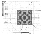
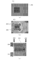
- FIGS. 1 to 6 show one of the two coil cross sections seen when the coil is cut along a plane including its winding axis and the periphery thereof.
- a magnetic field represented by a concentric magnetic flux 112 is generated by energization in a coil 111 in which square wires are wound in 3 layers ⁇ 3 rows.
- the region 113 having a large AC copper loss is mainly formed on the side far from the magnetic field center of each square line.
- the coil 111 is placed in an alternating external magnetic field (vertical magnetic field) along the winding axis direction represented by the magnetic flux 122 in FIG. 2, alternating current is applied to both sides of each row (vertical direction) formed by the square lines.
- a region 123 having a large copper loss appears.
- the distribution of the region 123 in FIG. 2 is different from that of the region 113 in FIG.
- the arrangement of conductive wires in a direction perpendicular to the winding axis of the coil is referred to as “layer”, and the arrangement of conductive wires in the direction parallel to the winding axis of the coil is referred to as “row (or winding)”.
- layer the arrangement of conductive wires in the direction perpendicular to the winding axis of the coil
- row or winding
- the magnetic field in the direction along the winding axis is referred to as a “vertical magnetic field” for convenience, but the winding axis may face in any direction, and “vertical” does not mean the direction of gravity.
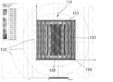
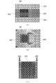
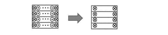
- a magnetic field represented by a concentric magnetic flux 132 is also generated by energization even in the coil 131 in which rectangular wires are wound in nine rows.
- a region 133 with a large AC copper loss appears along the short side of the cross section of the rectangular wire located at the center of the coil 131.
- a region 133 having a large AC copper loss appears along the long side as well as the short side of the cross section.
- the large copper loss region 143 extends along the short side and the long side of the cross section of all the rectangular wires including the rectangular wire located in the center of the coil 131.
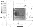
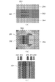
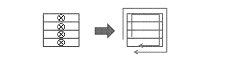
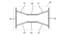
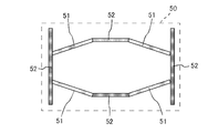
- a magnetic field represented by a concentric magnetic flux 152 is generated by energization even in a coil 151 in which a flat wire is wound in nine layers.
- a region 153 having a large AC copper loss appears in the central portion of the coil 151. That is, in the central portion of the coil 151, the region 153 having a large AC copper loss appears along the short side of the cross section of the rectangular wire.
- a region 153 having a large AC copper loss appears along the short side of each rectangular wire and along the long side.
- the magnetic flux 162 of the external magnetic field bends so as to avoid the coil 151 as shown in FIG. 163 is reduced to a region along the short side of the cross section of each rectangular wire, and becomes invisible in the region along the long side.
- the magnetic flux hardly penetrates the winding (conductor) and easily passes through the surface of the winding or the boundary between the windings.
- the ease of passage of magnetic flux differs at the boundary between the windings depending on the direction in which the boundary extends. Specifically, if the direction of the magnetic field is parallel to the direction in which the boundary between the windings extends (FIG. 4), the magnetic flux easily passes through the boundary between the windings, and the direction of the magnetic field is perpendicular to the direction in which the boundary between the windings extends. If it is (FIG. 6), it will be difficult for a magnetic flux to pass the boundary between windings.
- the inventor examined the change of the magnetic field when the core is arranged around the coil in order to control the direction of the magnetic field around the coil.
- the change in magnetic flux when the core is arranged in a magnetic field formed when a current is passed through the conductive wire was examined.
- the magnetic field formed by passing a current through the conductive line is concentric with the conductive line as the center in a plane including a cross section perpendicular to the length direction of the conductive line.
- the magnetic flux changes as the magnetic flux tries to pass through the core with high permeability.
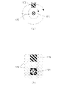
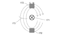
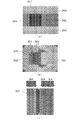
- FIGS. 7A and 7B it is assumed that a core 172 having a substantially square cross section is disposed in the magnetic field formed by the conductive wire 171. In that case, the magnetic flux 173 tends to pass through the core 172 where the magnetic permeability is high.
- the magnetic flux 173 remains substantially concentric and around the conductive wire 171.
- the magnetic flux distribution cannot be changed greatly.
- a pair of cores 172 are provided above and below the conductive wire 201 so as to face each other with the conductive wire 171 interposed therebetween, as shown in FIG.
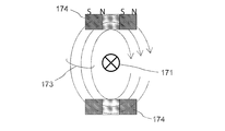
- FIG. 9 when a pair of cores 174 sandwiching another core member having a low magnetic permeability between two relatively short core members are arranged facing each other with the conductive wire 171 interposed therebetween Is the same.
- the length of the core 174 in the left-right direction in the drawing is relatively short and that the interval between the cores 174 is relatively wide.
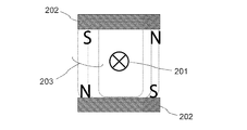
- FIGS. 10A and 10B when a core 202 having a rectangular cross section is arranged in the magnetic field formed by the conductive wire 201, more magnetic flux 203 passes through the core 202.
- the magnetic flux distribution changes relatively greatly.
- a substantially perpendicular magnetic field is formed on the left and right sides of the conductive line 201.
- the direction of the magnetic field around the conductive wire (coil) can be controlled if the core is appropriately disposed near the conductive wire (coil).
- the demagnetizing coefficient in the magnetic field direction formed by the conductive wires (coils) of the upper and lower cores is 0.
- a magnetic field close to perpendicular to the left and right sides of the conductive wire (coil) can be formed by setting it to 3 or less.
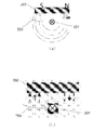
- FIG. 13 shows one of the two coil cross sections seen when the coil 231 is cut along a plane including the winding axis. The configuration shown in FIG.
- FIG. 13 corresponds to a state (see FIG. 10) in which an upper core 233 having a relatively high magnetic permeability on the one (upper) end surface side of the coil 231 and being long in the left-right direction in the drawing is arranged.
- a substantially vertical magnetic field is formed inside the inner peripheral surface of the coil 231 and outside the outer peripheral surface.
- the region 234 where the AC copper loss is large is biased toward the inner peripheral surface side and the outer peripheral surface side (the short side of each turn). That is, the leakage of magnetic flux of the coil 231 is reduced, and the AC resistance loss is suppressed.
- the coil 231 is substantially perpendicular to the left and right sides (the inner surface and the outer surface) (along the winding axis). Magnetic field (perpendicular magnetic field) can be formed. Thereby, the alternating current resistance loss resulting from the magnetic flux which flows into a coil from a core can be suppressed.
- the first model includes an edgewise coil 241, a dust core 242 disposed around the edgewise coil 241, and three pieces inserted in the magnetic path on the inner peripheral side of the edgewise coil 241. And a gap 243.
- the winding axis of the coil 241 is located on the right side of the drawing and extends in the vertical direction. That is, FIG. 14A shows one of the two coil cross sections seen when the coil component is cut along a plane including the winding axis and the periphery thereof. In this coil component, as shown in FIG. 14B, the magnetic flux is concentrated in the region 244 around the boundary between the coil 241 and the gap 243, that is, on the inner peripheral side of the coil 241.
- the region 245 having a large AC copper loss in the coil 241 is biased toward the inner peripheral side of the coil 241.
- the region 245 having a large AC copper loss is biased toward the inner peripheral side, and the AC copper loss by simulation was a large value of 172 W.
- the second model has an edgewise coil 251 and a casting core 252 arranged around the edgewise coil 251.
- this coil component as shown in FIG. 15B, the magnetic flux is concentrated in the region 253 along the long side of each rectangular wire on both the upper and lower sides of the coil 251.
- the region 254 having a large AC copper loss is biased toward the inner peripheral side and the outer peripheral side.
- a region 255 having a large AC copper loss extends along the long side of the cross section of each rectangular wire.
- the alternating current copper loss by simulation was 230W.
- the third model covers the edgewise coil 261, casting cores 262 and 263 respectively disposed on the inner and outer peripheral sides thereof, and the end face of the edgewise coil 261, and It has a pair of dust cores 264 connecting the two casting cores 262 and 263.
- the magnetic flux is concentrated in the region 265 along the short side of the rectangular wire.
- the region 266 where the AC copper loss is large is biased toward the inner peripheral side and the outer peripheral side of the coil 261, and the AC copper loss by simulation is the smallest of 48.2 W. Value.
- the fourth model has a configuration similar to that of FIG. 16 (a).
- This coil component is different from the coil component in FIG. 16A in that the number of windings of the edgewise coil 271 is two. Even if the number of windings is increased to two, as understood from the comparison between FIG. 16B and FIG. 17B, the magnetic flux distribution is not significantly different from the case where the number of windings is one. . That is, the magnetic flux is concentrated in the region 275 on the inner peripheral side and the outer peripheral side of the coil 271. Also, as shown in FIG. 17C, the region 276 where the AC copper loss is large is also biased toward the inner peripheral side and the outer peripheral side of the coil 271, and the AC copper loss by simulation is a small value of 49.5W. there were.
- the fifth model includes a coil 281 formed by winding a rectangular wire in three layers and three rows, and cast cores 262 and 263 disposed on the inner and outer peripheral sides thereof, respectively. And a pair of dust cores 264 that cover the end face of the coil 281 and connect the two casting cores 262 and 263.
- the magnetic flux is concentrated in the inner peripheral side and the outer peripheral side region 282 of the coil 281, and the region 283 along the boundary of the winding row inside the coil 281. There is also a concentration of magnetic flux.
- the region 284 having a large AC copper loss exists not only on the inner and outer peripheral sides of the coil 281 but also on the inside.
- the alternating current copper loss by simulation was 71.8W.
- the sixth model has a coil 291 formed by winding a rectangular wire in two layers and five rows, and casting cores 262 and 263 disposed on the inner peripheral side and the outer peripheral side, respectively. And a pair of dust cores 264 that cover the end face of the coil 291 and connect the two casting cores 262 and 263.
- the magnetic flux is concentrated in the inner and outer peripheral areas 292 of the coil 291, and in addition, the coil 291 is aligned along the boundary of the winding row. Concentration of magnetic flux occurs in the region 293.
- the number of regions 293 in which the magnetic flux is concentrated increases as the number of windings increases.
- the number of regions 294 having a large AC copper loss also increases as shown in FIG. The AC copper loss by simulation was 90.9W.
- the seventh model includes a flatwise coil 301, casting cores 262 and 263 respectively disposed on the inner and outer peripheral sides thereof, and covers the end face of the coil 301, and two It has a pair of dust cores 264 connecting the casting cores 262 and 263.
- the magnetic flux is concentrated in the inner peripheral side 302 and the outer peripheral side region 302 of the coil 301, and the region 303 along the boundary of the winding row is formed inside the coil 301. Concentration of magnetic flux occurs in The number of regions 303 where magnetic flux concentration occurs is further increased than in the case of FIG.
- the region 304 having a large AC copper loss also increased compared to the case of FIG.
- the alternating current copper loss by simulation also increased to 144.1W.
- a core having a relatively high magnetic permeability may be disposed in the four regions located at the corners.
- a core having a relatively low magnetic permeability is disposed in the inner peripheral surface and the outer peripheral surface.
- Relatively high permeability mu H is, for example, in the case of 100, a relatively low magnetic permeability mu L is about one of the well, good results have been obtained for example with 10.
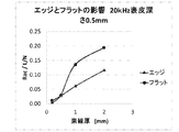
- the influence of the thickness of the winding (element wire) was examined.
- FIG. 26 it can be understood that the AC copper loss of the coil increases as the thickness of the winding (element wire) increases.
- the thickness of the winding (conductor) is equal to or thinner than the skin depth, there is a large difference in loss factor (Rac / L / N) between the edgewise coil ("edge") and the flatwise coil ("flat") There is no.
- the loss coefficient of the flatwise coil increases rapidly.
- the loss factor of the edgewise coil increases in a linear function as the wire thickness increases.
- the edgewise coil even if the thickness of the winding increases, there is no sudden increase in AC copper loss as in the case of the flatwise coil. Therefore, the use of edgewise coils is advantageous when the winding thickness is large.
- this invention aims at reducing alternating current copper loss by suppressing the magnetic flux which flows in into a coil from a core, it may not be all.
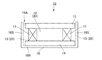
- the coil component 10 includes a coil 11, an inner peripheral core 12 disposed on the inner peripheral side of the coil 11, and an outer peripheral side of the coil 11.
- the outer peripheral side core 13 arrange
- the winding axis of the coil 11 is located at the center in the left-right direction in the figure and extends along the up-down direction in the figure. Note that FIG. 27 does not represent the usage state of the coil component 10, and the winding axis of the coil 11 may be directed in any direction during use. The same applies to other embodiments described later.
- the coil 11 is an edgewise coil wound so as to overlap windings (conductive wires) along the winding axis direction. That is, the coil 11 has a substantially rectangular cross-sectional shape and is formed by spirally winding a conductive wire (flat wire) (not shown) covered with an insulator (not shown). Specifically, the coil 11 according to the present embodiment is formed by winding a conductive wire in a spiral and square shape so as to have a linear winding axis. Therefore, the coil 11 of the present embodiment has a substantially square shape in a plane orthogonal to the winding axis. The coil 11 may further include an insulator that covers the periphery of a wound body formed by winding a conductive wire. In any case, the coil 11 has an inner peripheral surface, an outer peripheral surface, and a pair of end surfaces continuous with these.
- the inner peripheral core 12 is disposed inside the inner peripheral surface of the coil 11 so as to contact the inner peripheral surface of the coil 11.
- the outer peripheral side core 13 is arrange
- the inner peripheral core 12 and the outer peripheral core 13 are simultaneously formed using the same material. Specifically, the inner peripheral core 12 and the outer peripheral core 13 are formed by thermally curing a slurry 20 (see FIG. 31) made of soft magnetic metal powder, a thermosetting binder component, a solvent, and the like. Further, the inner peripheral core 12 and the outer peripheral core 13 have magnetic permeability (low ⁇ ) in a relatively low zero magnetic field. Specifically, the magnetic permeability of the inner core 12 and the outer core 13 is 3 to 15, preferably 7 to 12, particularly about 10. In the following description, a core formed by curing the slurry 20 may be referred to as a cast core.
- the pair of end face side cores 14 and 15 cover the pair of end faces of the coil 11 and mechanically and magnetically connect the inner peripheral side core 12 and the outer peripheral side core 13.
- the inner periphery side core 12, the outer periphery side core 13, and the end surface side cores 14 and 15 form a closed magnetic circuit.
- Each of the pair of end face side cores 14 and 15 is a dust core formed by compression-molding soft magnetic metal powder having high saturation magnetic flux density such as iron alloy powder with high pressure.
- Each of these end face side cores 14 and 15 has a plate-like shape having a substantially uniform thickness and a pair of flat main surfaces.
- the outer peripheral cores 14 and 15 have a higher magnetic permeability (high ⁇ ) in a zero magnetic field than the inner peripheral core 12 and the outer peripheral core 13.
- the magnetic permeability of the end face side cores 14 and 15 is 50 or more, preferably 50 to 150, and particularly preferably about 90.
- the end surface side cores 14 and 15 each have a size larger than the outer peripheral surface of the coil 11 and are outside the outer peripheral surface of the coil 11. Overhangs.
- the end face side cores 14 and 15 of the present embodiment have a quadrangular shape with rounded corners, and the edges protrude beyond the outer peripheral surface of the coil 11 in a bowl shape. Therefore, if the end face side cores 14 and 15 and the coil 11 are viewed along the direction of the winding axis of the coil 11, the coil 11 is hidden behind the end face side three cores 14 and 15 and cannot be seen.
- the present invention is not limited to this configuration.
- the end face side cores 14 and 15 do not have to protrude to the outer peripheral side over the entire circumference of the coil 11.
- the end face side cores 14 and 15 are outer peripheral from one set of sides of the coil 11 facing each other. It protrudes to the side (left-right direction in FIG. 27) and may not protrude from the other set of sides to the outer peripheral side (front-back direction in FIG. 27).
- it may have a shape called an EE (or EI) core.
- the end face portion of the coil corresponding to the other set of sides may be partly or entirely covered by the end face side cores 14 and 15, or part or the front part may be covered by the outer peripheral side core 13. Or a part or all of them may be exposed to the outside.
- the outer peripheral side core (second core member) 13 may not be disposed outside the outer peripheral surface of the coil corresponding to the other set of sides, and the outer peripheral surface of the coil is in direct contact with the case. Also good.
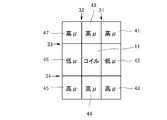
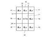
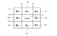
- the structure of the cores 12, 13, 14, and 15 can be said as follows from another viewpoint. That is, as shown in FIG. 28, in a cross section in which the coil component is cut along a plane including the winding axis of the coil 11 and a magnetic path that circulates in the core (12, 13, 14, 15), When the perimeter of each of the two coil cross sections seen in the cross section of the part is divided into eight regions 41 to 48 by four straight lines 31 to 34 along the inner peripheral surface, the outer peripheral surface and the end surface, they are located at the corners. In each of the four regions 41, 43, 45, and 47, a dust core (first core member, high ⁇ material) is arranged, and the region 42 located inside the inner peripheral surface and the region 46 located outside the outer peripheral surface. Each of the casting cores (second core member, low ⁇ ) is disposed, and the dust cores (third core member, high ⁇ ) are disposed in the regions 44 and 48 located outside the end surfaces, respectively.
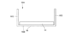
- the case 16 is made of a metal such as aluminum.
- the illustrated case 16 has an opening 16A and a bottom 16B in the direction in which the winding axis of the coil 11 extends, and a side surface 16S that connects the opening 16A and the bottom 16B. More specifically, the bottom portion 16B has a quadrangular shape with rounded corners, and the side surface portion 16S has a substantially rectangular tube shape.
- the inner peripheral side core 12, the outer peripheral side core 13, the end face side cores 14 and 15, and the coil 11 are disposed in the case 16. In the case 16, the inner peripheral core 12 and the outer peripheral core 13 are in close contact with the coil 11 and the end surface cores 14 and 15.
- the end surface side core 15 closer to the opening portion 16A than the bottom portion 16B is located away from the side surface portion 16S. That is, the end surface side core 15 is smaller than the side surface portion 16S in a plane orthogonal to the winding axis of the coil 11. A part of the outer peripheral side core 13 partially enters between the end surface side core 15 and the side surface portion 16S.
- the end surface side core 14 closer to the bottom portion 16B than the opening portion 16A is positioned away from the side surface portion 16S. That is, the end surface side core 14 is smaller than the side surface portion 16S in a plane orthogonal to the winding axis of the coil 11. A part of the outer peripheral side core 13 enters between the end surface side core 14 and the side surface portion 16S.
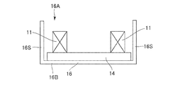
- the case 16 is prepared, and one end face side core 14 is placed on the bottom 16 ⁇ / b> B of the case 16. Since the end surface side core 14 of the present embodiment has a smaller size than the side surface portion 16S of the case 16, a gap is formed between the side surface portion 16S and the end surface side core 14. Because of such a design, even if the size of the end face side core 14 varies, the positional relationship between the end face side core 14 and the case 16 does not become a problem.
- the coil 11 is placed on one surface of the one end face side core 14.
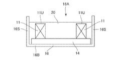
- the slurry 20 as the raw material of the inner peripheral core 12 and the outer peripheral core 13 is poured into the case 16 through the opening 16A until the coil 11 is completely immersed. That is, in the present embodiment, the upper surface (liquid surface) of the poured slurry 20 is located above the upper end 11U of the coil 11. The slurry 20 positioned above the upper end 11U of the coil 11 does not form the main parts of the inner peripheral core 12 and the outer peripheral core 13, but is extra. Similarly, the slurry 20 entering between the one end face side core 14 and the inner peripheral face 16S is also excessive. However, as will be described later, the presence of this excess slurry 20 can increase the degree of adhesion between the inner peripheral side core 12 and the outer peripheral side core 13 and the end face side core 15.
- the opening 16A is open in the direction of the winding axis of the coil 11, the space inside and outside the coil can be visually recognized, and the slurry 20 is poured into the inside and outside of the coil 11. Can do.
- both the inner peripheral core 12 and the outer peripheral core 13 can be cast cores.
- the other end face side core 15 is placed on the coil 11. At this time, the other end surface side core 15 is disposed so that the pair of end surface side cores 14 and 15 face each other. As described above, since the end surface side core 15 of the present embodiment has a smaller size than the side surface portion 16S of the case 16, a gap is formed between the side surface portion 16S and the end surface side core 14. Is done.
- an edgewise coil is used as the coil 11, and the inner peripheral side core 12 and the outer peripheral side core 13 that are cast cores are disposed on the inner peripheral side and the outer peripheral side, respectively.
- the side core 12 and the outer peripheral side core 13 are connected by a pair of end face side cores 14 and 15 which are dust cores.
- produces in the coil 11 can be reduced.
- inductance in a zero magnetic field in which no DC superimposed current is passed through the coil component 10 is suppressed, and the DC superimposed characteristics are improved. Can do.
- part of the core (specifically, the inner peripheral core 12 and the outer peripheral core 13) is formed using the slurry 20.
- the clearance gap between the coil 11 and the surrounding core (the inner peripheral side core 12, the outer peripheral side core 13, and the end surface side cores 14 and 15) can be eliminated.
- the variation in the characteristics of the coil component 10 depending on the assembly accuracy can be reduced or eliminated, and the backlash of the coil 11 can be suppressed, and noise during use of the coil component 10 can be reduced.
- the number of the compacting cores which are solid can be reduced, and an assembly
- the cost can be reduced by reducing the number of dust cores having a relatively high magnetic permeability and using casting cores having a relatively low magnetic permeability.
- the coil 11 has a quadrangular shape with rounded corners in a plane orthogonal to the winding axis, but the present invention is not limited to this.
- the coil 11 may have a circular or oval shape or a track shape for competition in a plane perpendicular to the winding axis of the coil.
- the casting core is used as the inner peripheral side core 12 and the outer peripheral side core 13, and the dust core is used as the end surface side cores 14 and 15.
- a dust core may be used as the inner peripheral core 12 and the outer peripheral core 13, and cast cores may be used as the end face side cores 14 and 15.
- these cores may be formed by infiltrating a resin into the molded magnetic powder and then curing the resin.
- the inner peripheral core 12, the magnetic permeability of the end face side cores 14, 15 in the zero magnetic field is higher than the magnetic permeability of the inner peripheral core 12 and the outer peripheral core 13 in the zero magnetic field.
- the outer peripheral side core 13 and the end surface side cores 14 and 15 should just be formed.
- a nonmagnetic gap material 51 is disposed in the inner circumferential space 50 of the coil 11 as shown in FIGS. 33 and 34 or 35 and 36. To do. That is, four rectangular plate-like gap members 51 are arranged in two upper and lower stages. The gap material 51 of each step is disposed so that the long sides are parallel to each other. The gap members 51 are fixed to each other by a support member 52 in order to facilitate assembly. Further, in order to facilitate the assembly and suppress the occurrence of AC copper loss, the gap material 51 may be disposed so as to leave a predetermined interval with the inner peripheral surface of the coil 11.
- the gap members 51 adjacent to the left and right are arranged with a space therebetween. May be. Furthermore, each gap member 51 is arranged so as to be inclined with respect to a plane perpendicular to the winding axis of the coil 11 so that bubbles that may be generated when the slurry 20 is poured are easily discharged.
- the shape, number and arrangement of the gap material 51 are not limited to the present embodiment. The shape, number and arrangement of the gap members 51 can be adjusted according to desired characteristics.
- Part of the end face side cores 14 and 15 of the coil component 10 according to the first embodiment is replaced with a casting core (low ⁇ ). Specifically, at least a part of the portion of the end face side cores 14 and 15 covering the end face of the coil 11 is replaced with a casting core.
- the periphery of the coil 11 in the cross section obtained by cutting the coil component along a plane including the coil winding axis and the magnetic path that circulates in the core, the periphery of the coil 11 (two coils seen in the cross section of the coil component).
- a compacted core (first core member, high ⁇ ) is disposed in each of 47.
- a casting core (second core member, low ⁇ ) is disposed in the region 42 located inside the inner peripheral surface of the coil 11 and the region 46 located outside the outer peripheral surface.
- a casting core (third core member, low ⁇ ) is disposed in at least a part of each of the regions 44 and 48 located outside the end face. In the remaining portions of the regions 44 and 48, a dust core is disposed.
- the casting core is usually arranged so as to be sandwiched between a pair of dust cores.
- the dust core disposed in the regions 44 and 48 may be formed integrally with the dust core disposed in any of the adjacent regions 41, 43, 45, and 47.
- the inductance in the zero magnetic field is lower than in the first embodiment, the inductance can be adjusted according to the application. Also in this embodiment, the gap material 51 described in the second embodiment may be arranged on the inner peripheral side of the coil 11 according to the characteristics to be obtained.
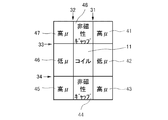
- Part of the end face side cores 14 and 15 of the coil component 10 according to the first embodiment is replaced with a nonmagnetic gap material. Specifically, at least a part of the portion covering the end face of the coil 11 is replaced with a nonmagnetic gap material.
- the periphery of the coil 11 in the cross section obtained by cutting the coil component along a plane including the winding axis of the coil 11 and the magnetic path that circulates in the core, the periphery of the coil 11 (two cross sections of the coil component can be seen).
- each coil cross section When the perimeter of each coil cross section is divided into eight regions 41 to 48 by four straight lines 31 to 34 along the inner peripheral surface, outer peripheral surface, and end surface, the four regions 41, 43, 45 located at the corners , 47 are each provided with a dust core (first core member, high ⁇ ).
- a casting core (second core member, low ⁇ ) is disposed in the region 42 located inside the inner peripheral surface of the coil 11 and the region 46 located outside the outer peripheral surface.
- a non-magnetic gap material is disposed at least partially in each of the regions 44 and 48 located outside the end face of the coil 11.
- the entire end surface of the coil 11 seems to be covered with a nonmagnetic gap, but in reality, most of the end surface of the coil 11 is covered with a dust core (third core member, high ⁇ ).
- the area covered by the nonmagnetic gap material is small. In this configuration, leakage flux from the nonmagnetic gap material to the coil 11 can be suppressed by using the edgewise coil. This is because the end face of the coil 11 is on the long side in the cross section of the rectangular wire.
- the gap material 51 described in the second embodiment may be arranged on the inner peripheral side of the coil 11 as in the third embodiment.
- a compacted core (first core member, high ⁇ ) is disposed in each of 47.
- a dust core (second core member, high ⁇ ) is also arranged in each of the region 42 located inside the inner peripheral surface of the coil 11 and the region 46 located outside the outer peripheral surface.
- cast cores (third core member, low ⁇ ) are arranged in the regions 44 and 48 located outside the end face.
- the dust core disposed in the region 42 may be formed integrally with the dust cores disposed in the adjacent regions 41 and 43, respectively.
- the dust core disposed in the region 46 may be formed integrally with the dust cores disposed in the adjacent regions 45 and 47, respectively. Also in this embodiment, there is little magnetic flux leakage to the coil 11, and the effect of reducing AC copper loss is obtained.
- the inner peripheral side core 12 and the outer peripheral side core 13 of the coil component according to the fifth embodiment are replaced with cast cores. That is, as shown in FIG. 40, in the cross section obtained by cutting the coil component along a plane including the winding axis of the coil and the magnetic path that circulates in the core, the periphery of the coil 11 Are divided into eight regions 41 to 48 by four straight lines 31 to 34 along the inner peripheral surface, the outer peripheral surface, and the end surface, and the four regions 41, 43, 45, and 47 located at the corners.
- a dust core (first core member, high ⁇ ) is disposed in each.
- a casting core (second core member, low ⁇ ) is disposed in at least a part of each of the region 42 located inside the inner peripheral surface of the coil 11 and the region 46 located outside the outer peripheral surface. Further, cast cores (third core member, low ⁇ ) are arranged in the regions 44 and 48 located outside the end face.
- a dust core is disposed in the remaining portions of the regions 42 and 46. In each of the regions 42 and 46, the casting core is usually arranged so as to be sandwiched between a pair of dust cores.
- the dust cores disposed in the regions 42 and 46 may be formed integrally with the dust cores disposed in any of the adjacent regions 41, 43, 45 and 47. Also in this embodiment, there is little magnetic flux leakage to the coil 11, and the effect of reducing AC copper loss is obtained.
- this invention is not limited to the said embodiment, A various change and deformation
- an edgewise coil or a flatwise coil wound with a flat wire is used as the coil 11, but the coil 11 may be a coil wound with a square wire or a round wire.
- the number of coil windings and the number of layers may be two or more, respectively.
- the number of coil windings is preferably 10 or less, and particularly preferably 2 or less.
- the number of coil layers is preferably 10 or less, and particularly preferably 2 or less.
- region around a coil was divided into 8 by the straight line along an inner peripheral surface, an outer peripheral surface, and an end surface, there may be some shift
- the four regions positioned at the corners may protrude to the casting core (low ⁇ ) side (up and down direction).
- the protrusion amount is desirably within 10% of the thickness in the vertical direction of the dust core.
- the protruding portion can be used for positioning at the time of assembly.
- the coil component of this invention is suitable for a reactor, especially a vehicle-mounted reactor, it can be applied to other coil components.
- the present invention is based on Japanese Patent Application No. 2015-164925 filed with the Japan Patent Office on August 24, 2015, the contents of which are incorporated herein by reference.
Abstract
Provided is a coil component comprising: a coil which includes an inner circumferential surface, an outer circumferential surface and, continuous therewith, a pair of end surfaces; and a core that surrounds the perimeter of the coil. In a cross-section in which the coil component is cut on a plane that includes the winding axis of the coil and a magnetic path that follows a winding path inside the core, when each periphery of the cross-section of the coil is divided into eight regions 41-48 by four straight lines 31-34 which follow the inner circumferential surface, the outer circumferential surface and the end surfaces, the following are provided as the core: first core members that are respectively disposed in four regions 41, 43, 45, 47 positioned in the corners of the coil component; second core members that are respectively disposed in a region 42 positioned on the inner side of the inner circumferential surface, and a region 46 positioned on the outer side of the outer circumferential surface; and third core members that are respectively disposed in regions positioned on the outer side of the end surfaces. The second core members and/or the third core members have, in a zero magnetic field, a magnetic permeability which is lower than that of the first core members. Due to this configuration, an increase in AC copper loss due to magnetic flux leak from a magnetic resistance unit is suppressed.
Description
本発明は、コアとコアの内部に埋設されたコイルとを備えるコイル部品に関する。
The present invention relates to a coil component including a core and a coil embedded in the core.
例えば、特許文献1には、このタイプのリアクトル(コイル部品)が開示されている。また、特許文献2には、タイプは異なるが、比透磁率の異なるコア部材を組み合わせて構成されたリアクトル用コアが開示されている。
For example, Patent Document 1 discloses a reactor (coil component) of this type. Patent Document 2 discloses a reactor core configured by combining core members having different types but different relative magnetic permeability.
特許文献1に開示されたリアクトルは、第1コア部と、第1コア部の外側に配されるコイルと、コイルの外側に配される第2コア部と、コイルの両端面を覆うように、第1及び第2コア部を相互に連結する連結コア部とを備えている。そして、第2コア部は、第1コア部に比べて大きい最大透磁率を有している。
The reactor disclosed in Patent Document 1 covers the first core part, the coil arranged outside the first core part, the second core part arranged outside the coil, and both end faces of the coil. And a connecting core portion that connects the first and second core portions to each other. And the 2nd core part has the largest maximum magnetic permeability compared with the 1st core part.
また、特許文献2に開示されたリアクトル用コアは、コイルで覆われる一対のコイル配置部と、コイルで覆われない一対の露出部とを備えている。そして、露出部は、コイル配置部よりも比透磁率が高くなるように構成されている。
Also, the reactor core disclosed in Patent Document 2 includes a pair of coil arrangement portions covered with a coil and a pair of exposed portions not covered with the coil. And the exposed part is comprised so that a relative magnetic permeability may become higher than a coil arrangement | positioning part.
車載用リアクトルなどのコイル部品では、磁気飽和を緩和するため磁気回路中に磁気抵抗部を設ける必要がある。しかしながら、磁気抵抗部は磁束漏れの原因となり、交流銅損を増加させるという問題点がある。そして、特許文献1及び特許文献2には、磁気抵抗部からの磁束漏れによる交流銅損について全く開示されていない。
In coil components such as in-vehicle reactors, it is necessary to provide a magnetoresistive part in the magnetic circuit to alleviate magnetic saturation. However, the magnetoresistive part causes a magnetic flux leakage and increases the AC copper loss. Patent Document 1 and Patent Document 2 do not disclose any AC copper loss due to magnetic flux leakage from the magnetoresistive portion.
そこで、本発明は、磁気抵抗部からの磁束漏れによる交流銅損を低減したコイル部品を提供することを目的とする。
Therefore, an object of the present invention is to provide a coil component in which AC copper loss due to magnetic flux leakage from the magnetoresistive portion is reduced.
本発明の第1の側面は、第1のコイル部品として、内周面と、外周面と、前記内周面及び前記外周面に連続する一対の端面とを有するコイルと、前記コイルの周囲の少なくとも一部を囲うコアとを有するコイル部品であって、前記コイル部品を前記コイルの巻軸と前記コア内を周回する磁路とを含む平面で切断した断面において、前記コイルの断面の各々の周囲を前記内周面、前記外周面及び前記端面に沿った4本の直線で8つの領域に区分したとき、前記コアとして、角に位置する4つの領域に夫々第1コア部材が配置され、前記内周面の内側に位置する領域及び前記外周面の外側に位置する領域に夫々第2コア部材が配置され、かつ前記端面の外側に位置する領域に夫々第3コア部材が配置されており、前記第2コア部材及び前記第3コア部材の少なくとも一方は、零磁界において前記第1コア部材よりも低い透磁率を有しているコイル部品を提供する。
A first side surface of the present invention includes, as a first coil component, a coil having an inner peripheral surface, an outer peripheral surface, a pair of end surfaces continuous to the inner peripheral surface and the outer peripheral surface, and a periphery of the coil. A coil component having a core surrounding at least a part thereof, wherein the coil component is cut by a plane including a winding axis of the coil and a magnetic path that circulates in the core; When the periphery is divided into eight regions by four straight lines along the inner peripheral surface, the outer peripheral surface and the end surface, the first core member is disposed in each of the four regions located at the corners as the core, A second core member is disposed in a region located inside the inner peripheral surface and a region located outside the outer peripheral surface, and a third core member is disposed in a region located outside the end surface, respectively. The second core member and the third core member. At least one of the A member provides a coil component having a lower magnetic permeability than the first core member at the zero magnetic field.
また、本発明の第2の側面は、第2のコイル部品として、第1のコイル部品であって、前記第2コア部材は、零磁界において前記第1コア部材よりも低い透磁率を有し、前記第3コア部材は、少なくとも一部が前記第2コア部材と同一の材料で構成されているコイル部品を提供する。
Moreover, the 2nd side surface of this invention is 1st coil components as 2nd coil components, Comprising: The said 2nd core member has a magnetic permeability lower than the said 1st core member in a zero magnetic field. The third core member provides a coil component that is at least partially made of the same material as the second core member.
また、本発明の第3の側面は、第3のコイル部品として、第1のコイル部品であって、前記第2コア部材は、零磁界において前記第1コア部材よりも低い透磁率を有し、前記第3コア部材は、前記第1コア部材と同一の材料で構成されているコイル部品を提供する。
Moreover, the 3rd side surface of this invention is 1st coil components as 3rd coil components, Comprising: The said 2nd core member has a magnetic permeability lower than the said 1st core member in a zero magnetic field. The third core member provides a coil component made of the same material as the first core member.
また、本発明の第4の側面は、第4のコイル部品として、第2又は第3のコイル部品であって、前記コイルの内周側に配置された前記第2コア部材中に非磁性ギャップが挿入されているコイル部品を提供する。
Moreover, the 4th side surface of this invention is a 2nd or 3rd coil component as a 4th coil component, Comprising: A nonmagnetic gap is provided in the said 2nd core member arrange | positioned at the inner peripheral side of the said coil. The coil component in which is inserted is provided.
また、本発明の第5の側面は、第5のコイル部品として、第2乃至第4のコイル部品のいずれかであって、前記第3コア部材の少なくとも一部が非磁性ギャップに置換されているコイル部品を提供する。
According to a fifth aspect of the present invention, as the fifth coil component, any one of the second to fourth coil components, wherein at least a part of the third core member is replaced with a nonmagnetic gap. Provide coil parts.
また、本発明の第6の側面は、第6のコイル部品として、第2乃至第5のコイル部品のいずれかであって、前記コイルは、平角線を螺旋状に巻回したエッジワイズコイルであるコイル部品を提供する。
The sixth aspect of the present invention is any one of the second to fifth coil components as the sixth coil component, wherein the coil is an edgewise coil in which a rectangular wire is spirally wound. Provide a coil component.
また、本発明の第7の側面は、第7のコイル部品として、第6のコイル部品であって、前記平角線は、表皮深さよりも大きい厚みを有しているコイル部品を提供する。
The seventh aspect of the present invention provides a coil component having a thickness larger than the skin depth, wherein the seventh coil component is a sixth coil component, wherein the flat wire is larger than the skin depth.
また、本発明の第8の側面は、第8のコイル部品として、第6又は第7のコイル部品であって、前記コイルは、巻列の数が10以下であるコイル部品を提供する。
Further, an eighth aspect of the present invention provides a sixth or seventh coil component as the eighth coil component, wherein the coil has a number of windings of 10 or less.
さらに、本発明の第9の側面は、第9のコイル部品として、第8のコイル部品であって、前記コイルは、巻列の数が2以下であるコイル部品を提供する。
Furthermore, a ninth aspect of the present invention provides an eighth coil component as the ninth coil component, wherein the coil has a number of windings of two or less.
さらにまた、本発明の第10の側面は、第10のコイル部品として、第2乃至第9のコイル部品のいずれかであって、前記第1コア部材は、圧粉コアであり、前記第2コア部材は、磁性体と樹脂を含む混合物を硬化したものであるコイル部品を提供する。
Furthermore, a tenth aspect of the present invention is any one of second to ninth coil components as a tenth coil component, wherein the first core member is a dust core, and the second coil component is a second core component. The core member provides a coil component obtained by curing a mixture containing a magnetic body and a resin.
また、本発明の第11の側面は、第11のコイル部品として、第1のコイル部品であって、前記第3コア部材は、零磁界において前記第1コア部材よりも低い透磁率を有し、前記第2コア部材は、少なくとも一部が前記第3コア部材と同一の材料で構成されているコイル部品を提供する。
The eleventh aspect of the present invention is the first coil component as the eleventh coil component, wherein the third core member has a lower magnetic permeability than the first core member in a zero magnetic field. The second core member provides a coil component that is at least partially made of the same material as the third core member.
さらに、本発明の第12の側面は、第12のコイル部品として、第1のコイル部品であって、前記第3コア部材は、零磁界において前記第1コア部材よりも低い透磁率を有し、前記第2コア部材は、前記第1コア部材と同一の材料で構成されているコイル部品を提供する。
The twelfth aspect of the present invention is the first coil component as the twelfth coil component, wherein the third core member has a lower magnetic permeability than the first core member in a zero magnetic field. The second core member provides a coil component made of the same material as the first core member.
さらにまた、本発明の第13の側面は、第13のコイル部品として、第11又は第12のコイル部品であって、前記コイルは、平角線を渦巻状に巻回したフラットワイズコイルであるコイル部品を提供する。
Furthermore, a thirteenth aspect of the present invention is an eleventh or twelfth coil component as a thirteenth coil component, wherein the coil is a flatwise coil obtained by winding a rectangular wire in a spiral shape. Provide parts.
コイル部品をコイルの巻軸とコア内を周回する磁路とを含む平面で切断した断面において、コイルの断面の各々の周囲を8つの領域に区分し、角に位置する4つの領域に夫々第1コア部材を配置する。また、内周面の内側に位置する領域及び外周面外側の領域に夫々第2コア部材を配置し、端面の外側に位置する領域に夫々第3コア部材が配置する。そして、第2コア部材及び第3コア部材の少なくとも一方として、第1コア部材よりも零磁界における透磁率が低いコア部材を用いる。この構成で、コイルへの磁束の漏れを低減し、交流銅損を低減することができる。
In a cross section obtained by cutting a coil component by a plane including a winding axis of the coil and a magnetic path that circulates in the core, the periphery of each of the cross sections of the coil is divided into eight regions, and each of the four regions located at the corners is divided into four regions. One core member is disposed. In addition, the second core member is disposed in a region located inside the inner peripheral surface and a region located outside the outer peripheral surface, and the third core member is disposed in a region located outside the end surface. A core member having a lower magnetic permeability in a zero magnetic field than the first core member is used as at least one of the second core member and the third core member. With this configuration, leakage of magnetic flux to the coil can be reduced, and AC copper loss can be reduced.
添付の図面を参照しながら下記の最良の実施の形態の説明を検討することにより、本発明の目的が正しく理解され、且つその構成についてより完全に理解されるであろう。
DETAILED DESCRIPTION OF THE INVENTION By studying the following description of the best mode with reference to the accompanying drawings, the object of the present invention will be understood correctly and the configuration thereof will be more fully understood.
本発明については多様な変形や様々な形態にて実現することが可能であるが、その一例として、図面に示すような特定の実施の形態について、以下に詳細に説明する。図面及び実施の形態は、本発明をここに開示した特定の形態に限定するものではなく、添付の請求の範囲に明示されている範囲内においてなされる全ての変形例、均等物、代替例をその対象に含むものとする。
The present invention can be realized in various modifications and various forms. As an example, specific embodiments as shown in the drawings will be described in detail below. The drawings and the embodiments are not intended to limit the invention to the specific forms disclosed herein, but to all modifications, equivalents, alternatives made within the scope of the appended claims. It shall be included in the object.
本発明の理解のため、まず、発明者が検討した事項について説明する。コイルに交流銅損を生じさせる主な原因として、表皮効果と近接効果が知られている。ここで、表皮効果は、コイルに流れる電流の周波数が高くなるほど大きくなる。さらに隣接する導体との作用による近接効果も問題となる。そこで、発明者は、交流銅損の低減について検討した。
In order to understand the present invention, the items studied by the inventor will be described first. The skin effect and proximity effect are known as the main causes of causing AC copper loss in the coil. Here, the skin effect increases as the frequency of the current flowing through the coil increases. Furthermore, the proximity effect due to the action of adjacent conductors also becomes a problem. Therefore, the inventor examined reduction of AC copper loss.
リアクトルのようなコイル部品は、コイルとコアとを有する。そして、コアは、コイルに近接効果を生じさせる原因となり得る。コアとして比較的高い透磁率を有するものを用いれば、コアからコイルへの磁束の漏れを少なくすることができ、コアに起因する近接効果を抑制することができる。しかしながら、コイル部品として、所望のインダクタンス特性や磁気飽和特性を得ようとする場合には、磁気回路中に磁気抵抗部を設ける必要がある。そして、磁気抵抗部は、コアからコイルへの磁束漏れによる交流抵抗損失増加の原因となる。なお、磁気抵抗部として、非磁性体ギャップや比較的低い透磁率を有するコア部材がある。非磁性体ギャップによる磁束の漏れは、ギャップの周囲に集中して発生する。
A coil component such as a reactor has a coil and a core. The core can cause a proximity effect in the coil. If a core having a relatively high magnetic permeability is used, leakage of magnetic flux from the core to the coil can be reduced, and the proximity effect due to the core can be suppressed. However, when a desired inductance characteristic or magnetic saturation characteristic is to be obtained as a coil component, it is necessary to provide a magnetoresistive portion in the magnetic circuit. And a magnetoresistive part becomes a cause of the alternating current resistance loss increase by the magnetic flux leakage from a core to a coil. As the magnetoresistive portion, there is a core member having a nonmagnetic gap and a relatively low magnetic permeability. Magnetic flux leakage due to the non-magnetic gap is concentrated around the gap.
磁気抵抗部からの漏れ磁束のコイルへの影響を知るため、発明者は、まず、コイルに対する外部磁界の影響について検討した。コイルの巻線として、角線(図1及び図2)又は平角線(図3乃至図6)を用いてシミュレーションを行った。また、平角線については、その断面の長辺が巻軸と平行になるように渦巻状に巻回したフラットワイズ(図3及び図4)と、断面の長辺が巻軸に垂直となるように螺旋状に巻回したエッジワイズ(図5及び図6)の2種類の巻回方式を採用した。なお、図1乃至図6において、巻軸はいずれも上下方向に延び、コイルの左側に位置している。即ち、図1乃至図6は、コイルをその巻軸を含む平面で切断した場合に見られる2つのコイル断面のうちの一方とその周辺を表している。
In order to know the influence of the leakage magnetic flux from the magnetoresistive section on the coil, the inventor first examined the influence of the external magnetic field on the coil. A simulation was performed using a square wire (FIGS. 1 and 2) or a flat wire (FIGS. 3 to 6) as the winding of the coil. In addition, with respect to the flat wire, a flat width (FIGS. 3 and 4) wound in a spiral shape so that the long side of the cross section is parallel to the winding axis, and the long side of the cross section is perpendicular to the winding axis. Two kinds of winding methods of edgewise (FIGS. 5 and 6) wound spirally were adopted. 1 to 6, all the winding shafts extend in the vertical direction and are located on the left side of the coil. That is, FIGS. 1 to 6 show one of the two coil cross sections seen when the coil is cut along a plane including its winding axis and the periphery thereof.
図1を参照すると、角線を3層×3列に巻回したコイル111では、通電により同心円状の磁束112で表される磁界が発生している。この状態で、交流銅損の大きい領域113は、主として、各角線の磁界中心から遠い側に形成される。一方、同コイル111を、図2に磁束122で表される巻軸方向に沿った交流の外部磁界(垂直磁界)中に置くと、角線が形成する各列(上下方向)の両側に交流銅損の大きい領域123が現れる。しかも、図2の領域123は、図1の領域113と、その分布が異なっている。なお、本明細書では、コイルの巻軸に直交する方向の導電線の並びを「層」と呼び、コイルの巻軸に平行な方向の導電線の並びを「列(又は巻列)」と呼ぶ。また、本明細書では、巻軸に沿った方向の磁界を、便宜上「垂直磁界」と呼ぶが、巻軸は任意の方向を向いてよく、「垂直」は、重力方向を意味しない。
Referring to FIG. 1, a magnetic field represented by a concentric magnetic flux 112 is generated by energization in a coil 111 in which square wires are wound in 3 layers × 3 rows. In this state, the region 113 having a large AC copper loss is mainly formed on the side far from the magnetic field center of each square line. On the other hand, when the coil 111 is placed in an alternating external magnetic field (vertical magnetic field) along the winding axis direction represented by the magnetic flux 122 in FIG. 2, alternating current is applied to both sides of each row (vertical direction) formed by the square lines. A region 123 having a large copper loss appears. Moreover, the distribution of the region 123 in FIG. 2 is different from that of the region 113 in FIG. In this specification, the arrangement of conductive wires in a direction perpendicular to the winding axis of the coil is referred to as “layer”, and the arrangement of conductive wires in the direction parallel to the winding axis of the coil is referred to as “row (or winding)”. Call. In this specification, the magnetic field in the direction along the winding axis is referred to as a “vertical magnetic field” for convenience, but the winding axis may face in any direction, and “vertical” does not mean the direction of gravity.
また、図3を参照すると、平角線を9列に巻回したコイル131でも、通電により同心円状の磁束132で表される磁界が発生している。この状態で、交流銅損の大きい領域133は、コイル131の中央部に位置する平角線では、その断面の短辺に沿って現れる。また、コイル131の左右両側部(外周側及び内周側)に位置する平角線では、その断面の短辺のみならず長辺に沿って交流銅損の大きい領域133が現れている。そして、同コイル131を巻軸方向に沿った交流の外部磁界(垂直磁界)中に置くと、図4に示すように、外部磁界を表す磁束142は、コイル内を通過するように曲がり、交流銅損の大きい領域143は、コイル131の中央部に位置する平角線も含む全ての平角線において、その断面の短辺及び長辺に沿って広がっている。
Referring also to FIG. 3, a magnetic field represented by a concentric magnetic flux 132 is also generated by energization even in the coil 131 in which rectangular wires are wound in nine rows. In this state, a region 133 with a large AC copper loss appears along the short side of the cross section of the rectangular wire located at the center of the coil 131. In addition, in the rectangular wire located on the left and right side portions (outer peripheral side and inner peripheral side) of the coil 131, a region 133 having a large AC copper loss appears along the long side as well as the short side of the cross section. When the coil 131 is placed in an alternating external magnetic field (vertical magnetic field) along the winding axis direction, the magnetic flux 142 representing the external magnetic field is bent so as to pass through the coil as shown in FIG. The large copper loss region 143 extends along the short side and the long side of the cross section of all the rectangular wires including the rectangular wire located in the center of the coil 131.
図5を参照すると、平角線を9層に巻回したコイル151でも、通電により同心円状の磁束152で表される磁界が発生している。また、この状態では、コイル131と同様に、交流銅損の大きい領域153が表れている。即ち、コイル151の中央部では、交流銅損の大きい領域153は、平角線の断面の短辺に沿って現れる。また、コイル151の上下両側部では、交流銅損の大きい領域153は、各平角線の短辺に沿って現れるとともに、長辺に沿って現れる。ところが、同コイル151を巻軸方向に沿った外部磁界(垂直磁界)中に置くと、図6に示すように、外部磁界の磁束162はコイル151を避けるように曲がり、交流銅損の大きい領域163は、各平角線の断面の短辺に沿った領域に縮小し、長辺に沿った領域では見えなくなる。
Referring to FIG. 5, a magnetic field represented by a concentric magnetic flux 152 is generated by energization even in a coil 151 in which a flat wire is wound in nine layers. In this state, similarly to the coil 131, a region 153 having a large AC copper loss appears. That is, in the central portion of the coil 151, the region 153 having a large AC copper loss appears along the short side of the cross section of the rectangular wire. In addition, on both upper and lower sides of the coil 151, a region 153 having a large AC copper loss appears along the short side of each rectangular wire and along the long side. However, when the coil 151 is placed in an external magnetic field (vertical magnetic field) along the winding axis direction, the magnetic flux 162 of the external magnetic field bends so as to avoid the coil 151 as shown in FIG. 163 is reduced to a region along the short side of the cross section of each rectangular wire, and becomes invisible in the region along the long side.
図1乃至図6から以下のことが理解される。即ち、磁束は、巻線(導体)を貫通し難く、巻線の表面又は巻線間の境界を通過し易い。また、巻線間の境界では、境界が延びている方向に応じて磁束の通過し易さが異なる。詳しくは、磁界の向きが巻線間の境界の延びる方向に平行(図4)であれば磁束は巻線間の境界を通過し易く、磁界の向きが巻線間の境界の延びる方向に垂直(図6)であれば磁束は巻線間の境界を通過し難い。
The following can be understood from FIGS. That is, the magnetic flux hardly penetrates the winding (conductor) and easily passes through the surface of the winding or the boundary between the windings. Moreover, the ease of passage of magnetic flux differs at the boundary between the windings depending on the direction in which the boundary extends. Specifically, if the direction of the magnetic field is parallel to the direction in which the boundary between the windings extends (FIG. 4), the magnetic flux easily passes through the boundary between the windings, and the direction of the magnetic field is perpendicular to the direction in which the boundary between the windings extends. If it is (FIG. 6), it will be difficult for a magnetic flux to pass the boundary between windings.
以上のことから、コイルの周囲における磁界の向きを制御することによりコイルへの磁束の進入(漏れ)を抑制又は阻止し、それによってコアに起因する交流抵抗損失を抑制できるものと推測される。
From the above, it is presumed that by controlling the direction of the magnetic field around the coil, entry (leakage) of magnetic flux to the coil can be suppressed or prevented, and thereby AC resistance loss caused by the core can be suppressed.
次に、発明者は、コイル周囲の磁界の向きを制御するために、コイルの周囲にコアを配置した場合の磁界の変化について検討した。まず、導電線が一本の場合について、導電線に電流を流したときに形成される磁界中にコアを配置した場合の磁束の変化について検討した。
Next, the inventor examined the change of the magnetic field when the core is arranged around the coil in order to control the direction of the magnetic field around the coil. First, in the case of a single conductive wire, the change in magnetic flux when the core is arranged in a magnetic field formed when a current is passed through the conductive wire was examined.
導電線が一本の場合、導電線に電流を流すことにより形成される磁界は、導電線の長さ方向に垂直な断面を含む平面において、導電線を中心とする同心円状になる。その磁界中にコアを配置すると、磁束は透磁率の高いコア内を通過しようとして磁束分布に変化が生じる。図7(a)及び図7(b)に示すように、導電線171が形成する磁界中に、断面が略正方形のコア172を配置したとする。その場合、磁束173は透磁率の高いところ、即ちコア172内を通過しようとする。しかし、コア172の左右方向(導電線171とコア172の中心とを結ぶ直線に垂直な方向)の長さが比較的短いため、磁束173は略同心円状のままであり、導電線171の周囲の磁束分布を大きく変化させることができない。図8に示すように、導電線171を挟んで互いに対向するように一対のコア172を導電線201の上下に設けた場合も同様である。また、図9に示すように、比較的短い2個のコア部材の間により透磁率の低い別のコア部材を挟んだ一対のコア174を、導電線171を挟んで互いに対向させて配置した場合も同様である。但し、この場合においては、コア174の図の左右方向の長さが比較的短いこと、及びコア174相互間の間隔が比較的広いことも関係しているものと考えられる。
When there is a single conductive line, the magnetic field formed by passing a current through the conductive line is concentric with the conductive line as the center in a plane including a cross section perpendicular to the length direction of the conductive line. When the core is arranged in the magnetic field, the magnetic flux changes as the magnetic flux tries to pass through the core with high permeability. As shown in FIGS. 7A and 7B, it is assumed that a core 172 having a substantially square cross section is disposed in the magnetic field formed by the conductive wire 171. In that case, the magnetic flux 173 tends to pass through the core 172 where the magnetic permeability is high. However, since the length of the core 172 in the left-right direction (the direction perpendicular to the straight line connecting the conductive wire 171 and the center of the core 172) is relatively short, the magnetic flux 173 remains substantially concentric and around the conductive wire 171. The magnetic flux distribution cannot be changed greatly. The same applies to the case where a pair of cores 172 are provided above and below the conductive wire 201 so as to face each other with the conductive wire 171 interposed therebetween, as shown in FIG. In addition, as shown in FIG. 9, when a pair of cores 174 sandwiching another core member having a low magnetic permeability between two relatively short core members are arranged facing each other with the conductive wire 171 interposed therebetween Is the same. However, in this case, it is considered that the length of the core 174 in the left-right direction in the drawing is relatively short and that the interval between the cores 174 is relatively wide.
一方、図10(a)及び図10(b)に示すように、導電線201が形成する磁界中に、断面が長方形のコア202を配置すると、より多くの磁束203がコア202を通過する。換言すると、磁界中に、図の左右方向に比較的長いコア202を配置すると、磁束分布が比較的大きく変化する。その結果、導電線201の左右両側には、垂直に近い磁界が形成される。図11に示すように、導電線201を挟んで互いに対向するように一対のコア202を導電線201の上下に設けると、導電線201の左右両側の磁界をより一層垂直磁界に近づけることができる。また、図12に示すように、比較的長い2個のコア部材の間に比較的短い(薄い)ギャップ材を挟んだ一対のコア204を、導電線201を挟むように対向配置した場合も同様である。
On the other hand, as shown in FIGS. 10A and 10B, when a core 202 having a rectangular cross section is arranged in the magnetic field formed by the conductive wire 201, more magnetic flux 203 passes through the core 202. In other words, when a relatively long core 202 is arranged in the left-right direction in the figure in the magnetic field, the magnetic flux distribution changes relatively greatly. As a result, a substantially perpendicular magnetic field is formed on the left and right sides of the conductive line 201. As shown in FIG. 11, when a pair of cores 202 are provided above and below the conductive wire 201 so as to face each other with the conductive wire 201 interposed therebetween, the magnetic fields on the left and right sides of the conductive wire 201 can be made closer to a vertical magnetic field. . Further, as shown in FIG. 12, the same applies when a pair of cores 204 having a relatively short (thin) gap material sandwiched between two relatively long core members are disposed so as to sandwich the conductive wire 201. It is.
以上のことから、導電線(コイル)の近くにコアを適切に配置すれば、導電線(コイル)の周囲の磁界の向きを制御できることが理解できる。発明者の検討によれば、一対のコア(上下コア)を電流中心に対して上下にかつ対称に配置する場合、上下コアの導電線(コイル)が形成する磁場方向における反磁界係数が0.3以下となるようにすることで、理論上は、導電線(コイル)の左右両側に垂直に近い磁界を形成することができる。これは、概ね、導電線(コイル)を挟んで対向配置される一対のコア(上下コア)を二辺とする四角形を想定した場合に、その四角形が上下コアを長辺とする長方形になる場合である。
From the above, it can be understood that the direction of the magnetic field around the conductive wire (coil) can be controlled if the core is appropriately disposed near the conductive wire (coil). According to the inventor's study, when the pair of cores (upper and lower cores) are arranged vertically and symmetrically with respect to the current center, the demagnetizing coefficient in the magnetic field direction formed by the conductive wires (coils) of the upper and lower cores is 0. In theory, a magnetic field close to perpendicular to the left and right sides of the conductive wire (coil) can be formed by setting it to 3 or less. This is roughly the case when assuming a quadrangle with two sides of a pair of cores (upper and lower cores) facing each other across a conductive wire (coil), the quadrangle becomes a rectangle with the upper and lower cores as long sides. It is.
次に、単一の導電線に代えてコイル(エッジワイズコイル)を用い、コイルの周囲に配置されたコアの影響を検討した。図13において、コイル231は、一方(上側)の端面を露出させるように、比較的透磁率の低い(μL=8)下部コア232に埋め込まれている。また、下部コア232の上には、コイル231の上側端面を覆うように、比較的透磁率の高い(μH=90)上部コア233が配置されている。コイル231の巻軸は図の右側に位置し、上下方向に延びている。即ち、図13は、コイル231を巻軸を含む平面で切断した場合に見られる2つのコイル断面のうちの一方を示している。図13に示す構成は、コイル231の一方(上側)の端面側に比較的高い透磁率を有しかつ図の左右方向に長い上部コア233を配置した状態(図10参照)に相当する。この構成において、コイル231の内周面の内側及び外周面の外側には、略垂直の磁界が形成されている。その結果、コイル231において、交流銅損が多い領域234は、内周面側及び外周面側(各ターンの短辺側)に偏っている。即ち、コイル231の磁束の漏れが低減され、交流抵抗損失が抑制されている。但し、エッジワイズコイル231の他方(下側)の端面近くでは、各平角線の長辺に沿って交流銅損の多い領域235が現れている。これは、図13に破線236~238で示されるように、磁束の通過する経路が異なるからだと推測される。即ち、エッジワイズコイル231の上側端面側では、コイル231に漏れる磁束がほとんどないのに対して、下側端面の近くではコイル231への磁束の漏れが存在するからだと考えられる。しかしながら、このような磁束の漏れは、エッジワイズコイル231の下側に、上部コア233と同様に比較的高い透磁率を持つ別のコアを配置することにより抑制できるものと予想される。
Next, instead of a single conductive wire, a coil (edgewise coil) was used, and the influence of the core arranged around the coil was examined. In FIG. 13, the coil 231 is embedded in the lower core 232 having a relatively low permeability (μ L = 8) so as to expose one (upper) end face. Further, an upper core 233 having a relatively high magnetic permeability (μ H = 90) is disposed on the lower core 232 so as to cover the upper end face of the coil 231. The winding axis of the coil 231 is located on the right side of the drawing and extends in the vertical direction. That is, FIG. 13 shows one of the two coil cross sections seen when the coil 231 is cut along a plane including the winding axis. The configuration shown in FIG. 13 corresponds to a state (see FIG. 10) in which an upper core 233 having a relatively high magnetic permeability on the one (upper) end surface side of the coil 231 and being long in the left-right direction in the drawing is arranged. In this configuration, a substantially vertical magnetic field is formed inside the inner peripheral surface of the coil 231 and outside the outer peripheral surface. As a result, in the coil 231, the region 234 where the AC copper loss is large is biased toward the inner peripheral surface side and the outer peripheral surface side (the short side of each turn). That is, the leakage of magnetic flux of the coil 231 is reduced, and the AC resistance loss is suppressed. However, in the vicinity of the other (lower) end face of the edgewise coil 231, a region 235 with a large AC copper loss appears along the long side of each rectangular wire. This is presumed to be because the paths through which the magnetic flux passes are different, as indicated by broken lines 236 to 238 in FIG. That is, it is considered that there is almost no magnetic flux leaking to the coil 231 on the upper end surface side of the edgewise coil 231, whereas there is magnetic flux leakage to the coil 231 near the lower end surface. However, it is expected that such leakage of magnetic flux can be suppressed by disposing another core having a relatively high magnetic permeability like the upper core 233 below the edgewise coil 231.
以上のように、コイル231の場合も単一の導電線(図10参照)の場合と同様に、その左右両側(内周面の内側及び外周面の外側)にほぼ垂直な(巻軸に沿った方向の)磁界(垂直磁界)を形成することができる。これにより、コアよりコイルに流入する磁束に起因する交流抵抗損失を抑制することができる。
As described above, in the case of the coil 231 as well as in the case of a single conductive wire (see FIG. 10), the coil 231 is substantially perpendicular to the left and right sides (the inner surface and the outer surface) (along the winding axis). Magnetic field (perpendicular magnetic field) can be formed. Thereby, the alternating current resistance loss resulting from the magnetic flux which flows into a coil from a core can be suppressed.
次に、コイルの上下に比較的高い透磁率を有する一対のコアを配置したコイル部品の磁束分布及び交流銅損について検討した。具体的には、コイルの巻線形状及び巻回方式を変えた5種類のコイル部品(第3乃至第7モデル)と、比較のための2つのコイル部品(第1及び第2モデル)についてシミュレーションを行った。シミュレーションにおいて、比較的透磁率の高いコアとして圧粉コアを、比較的透磁率の低いコアとして注型コアを想定した。なお、圧粉コアは軟磁性合金粉末を圧縮成型したものであり、注型コアは軟磁性合金粉末及びバインダ(樹脂)等を含むスラリーを硬化させたものである。
Next, the magnetic flux distribution and AC copper loss of a coil component in which a pair of cores having a relatively high magnetic permeability were arranged above and below the coil were examined. Specifically, five types of coil parts (third to seventh models) with different coil winding shapes and winding methods and two coil parts (first and second models) for comparison are simulated. Went. In the simulation, a dust core was assumed as a core having a relatively high permeability, and a cast core was assumed as a core having a relatively low permeability. The dust core is obtained by compression-molding soft magnetic alloy powder, and the casting core is obtained by curing a slurry containing soft magnetic alloy powder and binder (resin).
図14(a)を参照すると、第1モデルは、エッジワイズコイル241と、その周囲に配置された圧粉コア242と、エッジワイズコイル241の内周側において磁路中に挿入された3つのギャップ243とを有している。なお、コイル241の巻軸は図の右側に位置し、上下方向に延びている。即ち、図14(a)は、コイル部品を巻軸を含む平面で切断したときに見られる2つのコイル断面のうちの一方とその周囲を示している。このコイル部品では、図14(b)に示されるように、コイル241とギャップ243の境界周辺の領域244、即ちコイル241の内周側において磁束の集中が生じている。換言すると、エッジワイズコイル241とギャップ243の境界周辺において、圧粉コア242からエッジワイズコイル241へ多くの磁束が漏れている。このため、図14(c)に示されるように、コイル241における交流銅損の大きい領域245は、コイル241の内周側に偏っている。この構成では、交流銅損の大きい領域245が内周側に偏っており、シミュレーションによる交流銅損は172Wと大きな値であった。
Referring to FIG. 14A, the first model includes an edgewise coil 241, a dust core 242 disposed around the edgewise coil 241, and three pieces inserted in the magnetic path on the inner peripheral side of the edgewise coil 241. And a gap 243. The winding axis of the coil 241 is located on the right side of the drawing and extends in the vertical direction. That is, FIG. 14A shows one of the two coil cross sections seen when the coil component is cut along a plane including the winding axis and the periphery thereof. In this coil component, as shown in FIG. 14B, the magnetic flux is concentrated in the region 244 around the boundary between the coil 241 and the gap 243, that is, on the inner peripheral side of the coil 241. In other words, a large amount of magnetic flux leaks from the dust core 242 to the edgewise coil 241 around the boundary between the edgewise coil 241 and the gap 243. For this reason, as shown in FIG. 14C, the region 245 having a large AC copper loss in the coil 241 is biased toward the inner peripheral side of the coil 241. In this configuration, the region 245 having a large AC copper loss is biased toward the inner peripheral side, and the AC copper loss by simulation was a large value of 172 W.
図15(a)を参照すると、第2モデルは、エッジワイズコイル251と、その周囲に配置された注型コア252とを有している。このコイル部品では、図15(b)に見られるように、コイル251の上下両側において、各平角線の長辺に沿った領域253に磁束の集中が見られる。その結果、この構成では、図15(c)に示されるように、コイル251の上下中央部では、交流銅損の大きい領域254が内周側及び外周側に偏っているものの、上下両側では、各平角線の断面の長辺に沿って交流銅損の大きい領域255が広がっている。そして、シミュレーションによる交流銅損は230Wであった。
Referring to FIG. 15 (a), the second model has an edgewise coil 251 and a casting core 252 arranged around the edgewise coil 251. In this coil component, as shown in FIG. 15B, the magnetic flux is concentrated in the region 253 along the long side of each rectangular wire on both the upper and lower sides of the coil 251. As a result, in this configuration, as shown in FIG. 15C, in the upper and lower central portions of the coil 251, the region 254 having a large AC copper loss is biased toward the inner peripheral side and the outer peripheral side. A region 255 having a large AC copper loss extends along the long side of the cross section of each rectangular wire. And the alternating current copper loss by simulation was 230W.
図16(a)を参照すると、第3モデルは、エッジワイズコイル261と、その内周側及び外周側にそれぞれ配置された注型コア262,263と、エッジワイズコイル261の端面を覆い、かつ2つの注型コア262,263を連結する一対の圧粉コア264とを有している。このコイル部品では、図16(b)に見られるように、平角線の短辺に沿った領域265において磁束の集中が生じている。この構成では、図16(c)に示されるように、交流銅損の大きい領域266は、コイル261の内周側及び外周側に偏っており、シミュレーションによる交流銅損も48.2Wという最も小さな値であった。
Referring to FIG. 16 (a), the third model covers the edgewise coil 261, casting cores 262 and 263 respectively disposed on the inner and outer peripheral sides thereof, and the end face of the edgewise coil 261, and It has a pair of dust cores 264 connecting the two casting cores 262 and 263. In this coil component, as shown in FIG. 16B, the magnetic flux is concentrated in the region 265 along the short side of the rectangular wire. In this configuration, as shown in FIG. 16C, the region 266 where the AC copper loss is large is biased toward the inner peripheral side and the outer peripheral side of the coil 261, and the AC copper loss by simulation is the smallest of 48.2 W. Value.
図17(a)を参照すると、第4モデルは、図16(a)と類似の構成を有している。このコイル部品が図16(a)のコイル部品と異なる点は、エッジワイズコイル271の巻列の数が2列である点である。巻列の数を2列に増やしても、図16(b)と図17(b)との比較から理解されるように、その磁束分布は巻列の数が1列の場合と大きく変わらない。即ち、コイル271の内周側及び外周側の領域275において磁束の集中が生じている。また、図17(c)に示されるように、交流銅損の大きい領域276についても、コイル271の内周側及び外周側に偏っており、シミュレーションによる交流銅損も49.5Wという小さな値であった。
Referring to FIG. 17 (a), the fourth model has a configuration similar to that of FIG. 16 (a). This coil component is different from the coil component in FIG. 16A in that the number of windings of the edgewise coil 271 is two. Even if the number of windings is increased to two, as understood from the comparison between FIG. 16B and FIG. 17B, the magnetic flux distribution is not significantly different from the case where the number of windings is one. . That is, the magnetic flux is concentrated in the region 275 on the inner peripheral side and the outer peripheral side of the coil 271. Also, as shown in FIG. 17C, the region 276 where the AC copper loss is large is also biased toward the inner peripheral side and the outer peripheral side of the coil 271, and the AC copper loss by simulation is a small value of 49.5W. there were.
図18(a)を参照すると、第5モデルは、角線を3層3列に巻回して形成されたコイル281と、その内周側及び外周側にそれぞれ配置された注型コア262,263と、コイル281の端面を覆い、かつ2つの注型コア262,263を連結する一対の圧粉コア264とを有している。このコイル部品では、図18(b)に見られるように、コイル281の内周側及び外周側の領域282に磁束の集中が生じるとともに、コイル281の内部において巻列の境界に沿った領域283にも磁束の集中が生じている。この構成では、図18(c)に示されるように、交流銅損の大きい領域284はコイル281の内周側及び外周側のみならず内部にも存在する。そして、シミュレーションによる交流銅損は、71.8Wであった。
Referring to FIG. 18A, the fifth model includes a coil 281 formed by winding a rectangular wire in three layers and three rows, and cast cores 262 and 263 disposed on the inner and outer peripheral sides thereof, respectively. And a pair of dust cores 264 that cover the end face of the coil 281 and connect the two casting cores 262 and 263. In this coil component, as shown in FIG. 18B, the magnetic flux is concentrated in the inner peripheral side and the outer peripheral side region 282 of the coil 281, and the region 283 along the boundary of the winding row inside the coil 281. There is also a concentration of magnetic flux. In this configuration, as shown in FIG. 18C, the region 284 having a large AC copper loss exists not only on the inner and outer peripheral sides of the coil 281 but also on the inside. And the alternating current copper loss by simulation was 71.8W.
図19(a)を参照すると、第6モデルは、平角線を2層5列に巻回して形成されたコイル291と、その内周側及び外周側にそれぞれ配置された注型コア262,263と、コイル291の端面を覆い、かつ2つの注型コア262,263を連結する一対の圧粉コア264とを有している。このコイル部品でも、図19(b)に見られるように、コイル291の内周側及び外周側の領域292に磁束の集中が生じ、加えてコイル291の内部においても巻列の境界に沿った領域293に磁束の集中が生じている。図18(b)との比較から理解されるように、巻列の数の増加に伴い磁束の集中が生じる領域293の数も増えている。同様に、交流銅損の大きい領域294の数も、図19(c)に示されるように増加している。シミュレーションによる交流銅損は、90.9Wであった。
Referring to FIG. 19 (a), the sixth model has a coil 291 formed by winding a rectangular wire in two layers and five rows, and casting cores 262 and 263 disposed on the inner peripheral side and the outer peripheral side, respectively. And a pair of dust cores 264 that cover the end face of the coil 291 and connect the two casting cores 262 and 263. In this coil component as well, as shown in FIG. 19B, the magnetic flux is concentrated in the inner and outer peripheral areas 292 of the coil 291, and in addition, the coil 291 is aligned along the boundary of the winding row. Concentration of magnetic flux occurs in the region 293. As can be understood from the comparison with FIG. 18B, the number of regions 293 in which the magnetic flux is concentrated increases as the number of windings increases. Similarly, the number of regions 294 having a large AC copper loss also increases as shown in FIG. The AC copper loss by simulation was 90.9W.
図20(a)を参照すると、第7モデルは、フラットワイズコイル301と、その内周側及び外周側にそれぞれ配置された注型コア262,263と、コイル301の端面を覆い、かつ2つの注型コア262,263を連結する一対の圧粉コア264とを有している。このコイル部品でも、図20(b)に見られるように、コイル301の内周側及び外周側の領域302に磁束の集中が生じるとともに、コイル301の内部において巻列の境界に沿った領域303に磁束の集中が生じている。磁束の集中が生じる領域303の数は、図19(b)の場合よりもさらに増えている。また、図20(c)に示されるように、交流銅損の大きい領域304も、図19(c)の場合に比べて増加した。また、シミュレーションによる交流銅損も、144.1Wに増加した。
Referring to FIG. 20 (a), the seventh model includes a flatwise coil 301, casting cores 262 and 263 respectively disposed on the inner and outer peripheral sides thereof, and covers the end face of the coil 301, and two It has a pair of dust cores 264 connecting the casting cores 262 and 263. Also in this coil component, as shown in FIG. 20B, the magnetic flux is concentrated in the inner peripheral side 302 and the outer peripheral side region 302 of the coil 301, and the region 303 along the boundary of the winding row is formed inside the coil 301. Concentration of magnetic flux occurs in The number of regions 303 where magnetic flux concentration occurs is further increased than in the case of FIG. Further, as shown in FIG. 20C, the region 304 having a large AC copper loss also increased compared to the case of FIG. Moreover, the alternating current copper loss by simulation also increased to 144.1W.
図14乃至図20から理解されるように、コイルの上下に一対の圧粉コアを配置した第3から第7モデル(図16乃至図20)では、コア全体を圧粉コアとしギャップと組み合わせた第1モデル(図14)及びコア全体を注型コアとした第2モデル(図15)に比べて、交流銅損を低減することができる。これは、上述したように、コイルの内周側及び外周側に垂直に近い磁界が形成された結果、コイルへの漏れ磁束が減少したからだと推測される。
As understood from FIGS. 14 to 20, in the third to seventh models (FIGS. 16 to 20) in which a pair of dust cores are arranged above and below the coil, the entire core is a dust core and combined with a gap. Compared to the first model (FIG. 14) and the second model (FIG. 15) in which the entire core is a cast core, AC copper loss can be reduced. As described above, this is presumed to be because the magnetic flux leaking to the coil is reduced as a result of the formation of magnetic fields that are nearly perpendicular to the inner and outer peripheral sides of the coil.
また、図16乃至図20及び図21から理解されるように、コイルの巻列の数が増加すると交流銅損が増加する。これは、次のような理由によるものと考えられる。
Further, as understood from FIGS. 16 to 20 and FIG. 21, the AC copper loss increases as the number of coil windings increases. This is considered due to the following reasons.
図16の構成と同様の構成を有するコイル部品のコイル(エッジワイズコイル、1列×4層)に対して、図22の左図に示すように紙面奥向きの電流を流すと、同図の右図に矢印で示すような右回りの磁界が発生する。この磁界を打ち消すように、コイルの巻線(平角線)には、図23の左図に示すように複数の渦電流が発生する。しかしながら、これらの渦電流は各平角線の内部において互いに打ち消し合う。その結果、同図の右図に示すように、平角線の断面における長手方向端部の渦電流だけが残ることになるものと思われる。
When a current flowing in the depth direction of the drawing is applied to the coil of the coil component (edgewise coil, 1 row × 4 layers) having the same configuration as that of FIG. 16 as shown in the left diagram of FIG. A clockwise magnetic field as shown by an arrow in the right figure is generated. As shown in the left diagram of FIG. 23, a plurality of eddy currents are generated in the coil winding (flat wire) so as to cancel this magnetic field. However, these eddy currents cancel each other out inside each rectangular wire. As a result, it seems that only the eddy current at the end portion in the longitudinal direction in the cross section of the rectangular wire remains as shown in the right diagram of FIG.
平角線は絶縁膜で被覆されているため、渦電流の打ち消しは、平角線単位(各ターン)で発生する。換言すると、隣接する平角線同士の間では、渦電流の打ち消しは生じない。したがって、巻列の数が増加すると、残留する渦電流も増加する。例えば、巻列の数が2列の場合、図24の左図のようにコイルの両側部(内周側及び外周側)のみならず中央部にも渦電流が残る。しかしながら、渦電流の大きさは磁界の強さに応じて大きくなり、コイルの外側に比べてコイルの中心側の方が小さい。そのため、巻列の数が2列の場合には、図24の右図のように、両側部の渦電流が残るとみなすことができるものと思われる。
Since the flat wire is covered with an insulating film, eddy current cancellation occurs in flat wire units (each turn). In other words, eddy current cancellation does not occur between adjacent rectangular wires. Therefore, as the number of windings increases, the residual eddy current also increases. For example, when the number of windings is two, eddy currents remain not only on both sides (inner and outer sides) of the coil but also in the center as shown in the left diagram of FIG. However, the magnitude of the eddy current increases with the strength of the magnetic field, and is smaller on the center side of the coil than on the outside of the coil. Therefore, when the number of winding rows is 2, it can be considered that eddy currents on both sides remain as shown in the right diagram of FIG.
しかし、巻列の数が増えると、特開2013-26589号公報に記載された近接効果により、各列に渦電流が残る。例えば、図25の左図に示すように巻列の数が4列の場合には、同図の右図のように各列の端部に渦電流が残る。前述のように、コイルの外側ほど渦電流は大きく、中心部を除いて無視することができない。しかも、中央部以外では、隣接する巻列間の境界に発生する渦電流の向きは互いに逆向きである。このため、渦電流をより誘導しやすい状態となっており、交流銅損が増加するものと思われる。
However, as the number of winding rows increases, eddy currents remain in each row due to the proximity effect described in Japanese Patent Laid-Open No. 2013-26589. For example, when the number of winding rows is four as shown in the left diagram of FIG. 25, eddy currents remain at the ends of each row as shown in the right diagram of the same figure. As described above, the eddy current increases toward the outside of the coil and cannot be ignored except for the central portion. In addition, the directions of eddy currents generated at the boundary between adjacent winding rows are opposite to each other except in the central portion. For this reason, it is in the state which tends to induce an eddy current, and it is thought that an alternating current copper loss increases.
このように、巻列の数が増加すると交流銅損は増加する。それでも、図21から理解されるように、コイルの上下に一対の圧粉コアを配置した第3乃至第7モデル(「ハイブリッド」、図16から図20)は、コアを全て圧粉コアとしギャップを設けた場合(「圧粉3Gap」(第1モデル(図14)及びそれと同様の構成を有するコイル部品))やコアを全て注型コアとした場合(「注型μ11(零磁場における透磁率μ=11の注型コア)」、第2モデル(図15)及びそれと同様の構成を有するコイル部品)に比べて交流銅損を大幅に低減することができる。これは、巻列の数を10にした場合でも言えることである。
Thus, AC copper loss increases as the number of windings increases. Still, as can be understood from FIG. 21, the third to seventh models (“hybrid”, FIGS. 16 to 20) in which a pair of dust cores are arranged above and below the coil have the core as a dust core and a gap. ("Green powder 3Gap" (first model (Fig. 14) and coil parts having the same configuration)) or a case where all cores are cast cores ("cast μ11 (permeability in zero magnetic field) As compared with the second model (FIG. 15) and a coil component having the same configuration), the AC copper loss can be greatly reduced. This is true even when the number of winding rows is 10.
なお、第3乃至第7モデルでは、コイルの上下に配置されるコアとして圧粉磁心を想定したが、コイルの端面を覆う部分については、少なくともその一部を注型コアや非磁性ギャップに置き換えても、交流銅損の大幅な増加は見られなかった。したがって、少なくともコイルの角に対応する領域に比較的高い透磁率を有するコアを配置すれば、交流銅損の低減が見込まれる。換言すると、コイル部品をコイルの巻軸とコア内を周回する磁路とを含む平面で切断した断面において、コイルの断面の各々の周囲を内周面、外周面及び端面に沿った4本の直線で8つの領域に区分したとき、角に位置する4つの領域に比較的高い透磁率を有するコアを配置すればよい。このとき、内周面の内側及び外周面の外側の領域には、比較的低い透磁率を有するコアを配置する。比較的高い透磁率μHが、例えば100の場合、比較的低い透磁率μLはその十分の一程度、例えば10とすれば良好な結果が得られる。
In the third to seventh models, dust cores are assumed as the cores disposed above and below the coil. However, at least a part of the core that covers the end face of the coil is replaced with a casting core or a nonmagnetic gap. However, there was no significant increase in AC copper loss. Therefore, if a core having a relatively high magnetic permeability is disposed at least in a region corresponding to the corner of the coil, reduction of AC copper loss is expected. In other words, in the cross section obtained by cutting the coil component along a plane including the winding axis of the coil and the magnetic path that circulates in the core, the periphery of each of the cross sections of the coil is four along the inner peripheral surface, the outer peripheral surface, and the end surface. When a straight line is divided into eight regions, a core having a relatively high magnetic permeability may be disposed in the four regions located at the corners. At this time, a core having a relatively low magnetic permeability is disposed in the inner peripheral surface and the outer peripheral surface. Relatively high permeability mu H is, for example, in the case of 100, a relatively low magnetic permeability mu L is about one of the well, good results have been obtained for example with 10.
上述した発明者による検討では、コイルの巻軸に平行な磁界(垂直磁界)に着目した。しかし、コイルの巻軸に直交する方向(径方向)の磁界に注目した場合にも、同様の結果が期待できる。即ち、コイルの内周側及び外周側に比較的高い透磁率を有するコアを配置すれば、コイル端面の外側の磁界を制御でき、それによって、コイルの交流銅損の低減が期待できる。なお、上述した、コイル部品の断面において、角に位置する4つの領域に比較的高い透磁率を有するコアを配置する構成では、垂直磁界のみならず、径方向の磁界についても制御することができる。径方向の磁界に着目した場合には、垂直磁界に着目した場合とは異なるコイルを用いることが望ましい。即ち、この場合、コイルとして、端面に露出する導電線同士の境界の数が少ないもの(例えば、フラットワイズコイル)を用いることが望ましい。
In the above examination by the inventors, attention was paid to a magnetic field (vertical magnetic field) parallel to the winding axis of the coil. However, the same result can be expected when focusing on the magnetic field in the direction (radial direction) perpendicular to the winding axis of the coil. That is, if a core having a relatively high magnetic permeability is disposed on the inner and outer peripheral sides of the coil, the magnetic field outside the coil end face can be controlled, thereby reducing the AC copper loss of the coil. In the above-described configuration in which the cores having relatively high magnetic permeability are arranged in the four regions located at the corners in the cross section of the coil component, not only the vertical magnetic field but also the radial magnetic field can be controlled. . When focusing on the magnetic field in the radial direction, it is desirable to use a different coil than when focusing on the vertical magnetic field. That is, in this case, it is desirable to use a coil having a small number of boundaries between conductive wires exposed on the end face (for example, a flatwise coil).
次に、巻線(素線)の厚みの影響について検討した。図26を参照すると、巻線(素線)の厚みが増加するに従い、コイルの交流銅損が増加することが理解できる。巻線(導体)の厚みが表皮深さと同じかそれより薄い場合は、エッジワイズコイル(「エッジ」)とフラットワイズコイル(「フラット」)とで損失係数(Rac/L/N)に大きな差はない。しかしながら、巻線の厚みが表皮深さよりも厚くなると、フラットワイズコイルの損失係数は急激に増加する。これに対して、エッジワイズコイルの損失係数は、素線の厚みの増加に伴い一次関数的に増加する。このように、エッジワイズコイルでは、巻線の厚みが増加しても、フラットワイズコイルの場合のような急激な交流銅損の増加はない。したがって、エッジワイズコイルの使用は、巻線の厚みが大きい場合に有利である。
Next, the influence of the thickness of the winding (element wire) was examined. Referring to FIG. 26, it can be understood that the AC copper loss of the coil increases as the thickness of the winding (element wire) increases. When the thickness of the winding (conductor) is equal to or thinner than the skin depth, there is a large difference in loss factor (Rac / L / N) between the edgewise coil ("edge") and the flatwise coil ("flat") There is no. However, when the thickness of the winding becomes thicker than the skin depth, the loss coefficient of the flatwise coil increases rapidly. On the other hand, the loss factor of the edgewise coil increases in a linear function as the wire thickness increases. Thus, in the edgewise coil, even if the thickness of the winding increases, there is no sudden increase in AC copper loss as in the case of the flatwise coil. Therefore, the use of edgewise coils is advantageous when the winding thickness is large.
上記検討の結果、発明者は、本発明に想到するに至った。なお、本発明は、コアからコイルに流入する磁束を抑制することにより交流銅損を低減することを目指したものであるが、それがすべてではない可能性がある。
As a result of the above examination, the inventor came up with the present invention. In addition, although this invention aims at reducing alternating current copper loss by suppressing the magnetic flux which flows in into a coil from a core, it may not be all.
(第1の実施の形態)
次に、本発明の第1の実施の形態について詳細に説明する。図27に示されるように、本発明の第1の実施の形態によるコイル部品10は、コイル11と、コイル11の内周側に配置される内周側コア12と、コイル11の外周側に配置される外周側コア13と、一対の端面側コア14,15と、これらを収容するケース16とを備えている。図27において、コイル11の巻軸は、図の左右方向中央に位置し、図の上下方向に沿って延びている。なお、図27は、コイル部品10の使用状態を表すものではなく、使用時において、コイル11の巻軸は任意の方向を向いてよい。後述する他の実施の形態においても同様である。 (First embodiment)
Next, the first embodiment of the present invention will be described in detail. As shown in FIG. 27, thecoil component 10 according to the first embodiment of the present invention includes a coil 11, an inner peripheral core 12 disposed on the inner peripheral side of the coil 11, and an outer peripheral side of the coil 11. The outer peripheral side core 13 arrange | positioned, a pair of end surface side cores 14 and 15 and the case 16 which accommodates these are provided. In FIG. 27, the winding axis of the coil 11 is located at the center in the left-right direction in the figure and extends along the up-down direction in the figure. Note that FIG. 27 does not represent the usage state of the coil component 10, and the winding axis of the coil 11 may be directed in any direction during use. The same applies to other embodiments described later.
次に、本発明の第1の実施の形態について詳細に説明する。図27に示されるように、本発明の第1の実施の形態によるコイル部品10は、コイル11と、コイル11の内周側に配置される内周側コア12と、コイル11の外周側に配置される外周側コア13と、一対の端面側コア14,15と、これらを収容するケース16とを備えている。図27において、コイル11の巻軸は、図の左右方向中央に位置し、図の上下方向に沿って延びている。なお、図27は、コイル部品10の使用状態を表すものではなく、使用時において、コイル11の巻軸は任意の方向を向いてよい。後述する他の実施の形態においても同様である。 (First embodiment)
Next, the first embodiment of the present invention will be described in detail. As shown in FIG. 27, the
コイル11は、巻軸方向に沿って巻線(導電線)を重ねるように巻回されたエッジワイズコイルである。即ち、コイル11は、略長方形の断面形状を持ち、周囲を絶縁体(図示せず)で被覆された導電線(平角線)(図示せず)を螺旋状に巻回して形成される。詳しくは、本実施の形態のコイル11は、導電線を直線状の巻軸を有するように螺旋状かつ四角形状に巻回して形成される。したがって、本実施の形態のコイル11は、巻軸と直交する面内において、略四角形の形状を有している。コイル11は、導電線を巻回して形成した巻回体の周囲を覆う絶縁体を更に有していてもよい。いずれにしても、コイル11は、内周面と外周面及びこれらに連続する一対の端面を有している。
The coil 11 is an edgewise coil wound so as to overlap windings (conductive wires) along the winding axis direction. That is, the coil 11 has a substantially rectangular cross-sectional shape and is formed by spirally winding a conductive wire (flat wire) (not shown) covered with an insulator (not shown). Specifically, the coil 11 according to the present embodiment is formed by winding a conductive wire in a spiral and square shape so as to have a linear winding axis. Therefore, the coil 11 of the present embodiment has a substantially square shape in a plane orthogonal to the winding axis. The coil 11 may further include an insulator that covers the periphery of a wound body formed by winding a conductive wire. In any case, the coil 11 has an inner peripheral surface, an outer peripheral surface, and a pair of end surfaces continuous with these.
内周側コア12は、コイル11の内周面に接するように、コイル11の内周面の内側に配置される。また、外周側コア13は、コイル11の外周面に接するように、コイル11の外周面の外側に配置される。これら内周側コア12と外周側コア13は、同一の材料を用いて同時に形成される。具体的には、内周側コア12及び外周側コア13は、軟磁性金属粉末、熱硬化性バインダ成分、溶媒等からなるスラリー20(図31参照)を熱硬化させて形成される。また、内周側コア12と外周側コア13は、比較的低い零磁界における透磁率(低μ)を有する。具体的には、内周側コア12と外周側コア13の透磁率は、3~15であり、好ましくは7~12であり、特に10程度が好ましい。なお、以下の説明において、スラリー20を硬化させて形成したコアを、注型コアと呼ぶことがある。
The inner peripheral core 12 is disposed inside the inner peripheral surface of the coil 11 so as to contact the inner peripheral surface of the coil 11. Moreover, the outer peripheral side core 13 is arrange | positioned on the outer side of the outer peripheral surface of the coil 11 so that the outer peripheral surface of the coil 11 may be contact | connected. The inner peripheral core 12 and the outer peripheral core 13 are simultaneously formed using the same material. Specifically, the inner peripheral core 12 and the outer peripheral core 13 are formed by thermally curing a slurry 20 (see FIG. 31) made of soft magnetic metal powder, a thermosetting binder component, a solvent, and the like. Further, the inner peripheral core 12 and the outer peripheral core 13 have magnetic permeability (low μ) in a relatively low zero magnetic field. Specifically, the magnetic permeability of the inner core 12 and the outer core 13 is 3 to 15, preferably 7 to 12, particularly about 10. In the following description, a core formed by curing the slurry 20 may be referred to as a cast core.
一対の端面側コア14,15は、コイル11の一対の端面を覆い、内周側コア12と外周側コア13とを機械的及び磁気的に連結する。その結果、内周側コア12、外周側コア13及び端面側コア14,15は、閉磁路を形成する。一対の端面側コア14,15の各々は、鉄合金粉末等の飽和磁束密度の高い軟磁性金属粉末を、高い圧力によって圧縮成型して形成された圧粉コアである。これらの端面側コア14,15の各々は、実質的に均一な厚みと、一対の平らな主表面を有する板状の形状を有している。また、外周側コア14,15は、内周側コア12と外周側コア13に比較して、零磁界において高い透磁率(高μ)を有する。具体的には、端面側コア14,15の透磁率は50以上であり、好ましくは50~150であり、特に90程度が好ましい。
The pair of end face side cores 14 and 15 cover the pair of end faces of the coil 11 and mechanically and magnetically connect the inner peripheral side core 12 and the outer peripheral side core 13. As a result, the inner periphery side core 12, the outer periphery side core 13, and the end surface side cores 14 and 15 form a closed magnetic circuit. Each of the pair of end face side cores 14 and 15 is a dust core formed by compression-molding soft magnetic metal powder having high saturation magnetic flux density such as iron alloy powder with high pressure. Each of these end face side cores 14 and 15 has a plate-like shape having a substantially uniform thickness and a pair of flat main surfaces. Further, the outer peripheral cores 14 and 15 have a higher magnetic permeability (high μ) in a zero magnetic field than the inner peripheral core 12 and the outer peripheral core 13. Specifically, the magnetic permeability of the end face side cores 14 and 15 is 50 or more, preferably 50 to 150, and particularly preferably about 90.
詳しくは、コイル11の巻軸と直交する面内において、端面側コア14,15は、夫々、コイル11の外周面よりも大きいサイズを有しており、且つ、コイル11の外周面よりも外側に張り出している。換言すると、本実施の形態の端面側コア14,15は、角を丸めた四角形状を有しており、その縁部はコイル11の外周面を越えて鍔状に突き出している。そのため、仮に端面側コア14,15とコイル11とをコイル11の巻軸の方向に沿って見た場合、コイル11は、端面側3コア14,15に隠れて見えない。但し、本発明は、この構成に限られない。即ち、端面側コア14,15は、コイル11の全周に亘って外周側へ張り出していなくてもよい。例えば、コイル11が平面視で(図27の上方から見て)略四角形の場合、端面側コア14,15は、コイル11の互いに対向する二組の辺のうちの一方の組の辺から外周側(図27の左右方向)へ張り出し、他方の組の辺から外周側(図27の表裏方向)へ張り出していないものであってよい。具体的には、EE(又はEI)コアと呼ばれるような形状であってもよい。この場合、他方の組の辺に相当するコイルの端面部分は、端面側コア14,15によって一部又は全部が覆われていてもよいし、外周側コア13により一部又は前部が覆われていてもよいし、あるいは、一部または全部が外部に露出していてもよい。また、他方の組の辺に相当するコイルの外周面の外側には、外周側コア(第2コア部材)13が配置されていなくてもよく、コイルの外周面がケースに直接接触していてもよい。
Specifically, in the plane orthogonal to the winding axis of the coil 11, the end surface side cores 14 and 15 each have a size larger than the outer peripheral surface of the coil 11 and are outside the outer peripheral surface of the coil 11. Overhangs. In other words, the end face side cores 14 and 15 of the present embodiment have a quadrangular shape with rounded corners, and the edges protrude beyond the outer peripheral surface of the coil 11 in a bowl shape. Therefore, if the end face side cores 14 and 15 and the coil 11 are viewed along the direction of the winding axis of the coil 11, the coil 11 is hidden behind the end face side three cores 14 and 15 and cannot be seen. However, the present invention is not limited to this configuration. That is, the end face side cores 14 and 15 do not have to protrude to the outer peripheral side over the entire circumference of the coil 11. For example, when the coil 11 is substantially quadrangular in plan view (viewed from above in FIG. 27), the end face side cores 14 and 15 are outer peripheral from one set of sides of the coil 11 facing each other. It protrudes to the side (left-right direction in FIG. 27) and may not protrude from the other set of sides to the outer peripheral side (front-back direction in FIG. 27). Specifically, it may have a shape called an EE (or EI) core. In this case, the end face portion of the coil corresponding to the other set of sides may be partly or entirely covered by the end face side cores 14 and 15, or part or the front part may be covered by the outer peripheral side core 13. Or a part or all of them may be exposed to the outside. Further, the outer peripheral side core (second core member) 13 may not be disposed outside the outer peripheral surface of the coil corresponding to the other set of sides, and the outer peripheral surface of the coil is in direct contact with the case. Also good.
コア12,13,14及び15の構成は、別の見方をすると次の様に言える。即ち、図28に示すように、コイル部品をコイル11の巻軸とコア(12,13、14,15)内を周回する磁路とを含む平面で切断した断面において、コイル11の周囲(コイル部品の断面に見られる2つのコイル断面の各々の周囲)を内周面、外周面及び端面に沿った4本の直線31~34で8つの領域41~48に区分したとき、角に位置する4つの領域41,43,45,47に夫々圧粉コア(第1コア部材、高μ材)が配置され、内周面の内側に位置する領域42及び外周面の外側に位置する領域46に夫々注型コア(第2コア部材、低μ)が配置され、端面の外側に位置する領域44,48に夫々圧粉コア(第3コア部材、高μ)が配置されている。
The structure of the cores 12, 13, 14, and 15 can be said as follows from another viewpoint. That is, as shown in FIG. 28, in a cross section in which the coil component is cut along a plane including the winding axis of the coil 11 and a magnetic path that circulates in the core (12, 13, 14, 15), When the perimeter of each of the two coil cross sections seen in the cross section of the part is divided into eight regions 41 to 48 by four straight lines 31 to 34 along the inner peripheral surface, the outer peripheral surface and the end surface, they are located at the corners. In each of the four regions 41, 43, 45, and 47, a dust core (first core member, high μ material) is arranged, and the region 42 located inside the inner peripheral surface and the region 46 located outside the outer peripheral surface. Each of the casting cores (second core member, low μ) is disposed, and the dust cores (third core member, high μ) are disposed in the regions 44 and 48 located outside the end surfaces, respectively.
再び、図27を参照すると、ケース16は、例えばアルミニウム等の金属からなる。図示されたケース16は、コイル11の巻軸の延びる方向において開口部16A及び底部16Bを有すると共に、開口部16Aと底部16Bとを繋ぐ側面部16Sを有している。より具体的には、底部16Bは角を丸めた四角形状を有しており、側面部16Sは略四角筒形状を有している。内周側コア12、外周側コア13、端面側コア14,15及びコイル11は、ケース16内に配置されている。ケース16内において、内周側コア12及び外周側コア13は、コイル11と端面側コア14,15に対して密着している。底部16Bよりも開口部16Aに近い方の端面側コア15は、側面部16Sから離れて位置している。即ち、コイル11の巻軸と直交する平面内において、端面側コア15は、側面部16Sよりも小さい。このような端面側コア15と側面部16Sとの間には、外周側コア13の一部が部分的に入り込んでいる。同様に、開口部16Aよりも底部16Bに近い方の端面側コア14は、側面部16Sから離れて位置している。即ち、コイル11の巻軸と直交する平面内において、端面側コア14は、側面部16Sよりも小さい。このような端面側コア14と側面部16Sとの間には、外周側コア13の一部が入り込んでいる。
Referring to FIG. 27 again, the case 16 is made of a metal such as aluminum. The illustrated case 16 has an opening 16A and a bottom 16B in the direction in which the winding axis of the coil 11 extends, and a side surface 16S that connects the opening 16A and the bottom 16B. More specifically, the bottom portion 16B has a quadrangular shape with rounded corners, and the side surface portion 16S has a substantially rectangular tube shape. The inner peripheral side core 12, the outer peripheral side core 13, the end face side cores 14 and 15, and the coil 11 are disposed in the case 16. In the case 16, the inner peripheral core 12 and the outer peripheral core 13 are in close contact with the coil 11 and the end surface cores 14 and 15. The end surface side core 15 closer to the opening portion 16A than the bottom portion 16B is located away from the side surface portion 16S. That is, the end surface side core 15 is smaller than the side surface portion 16S in a plane orthogonal to the winding axis of the coil 11. A part of the outer peripheral side core 13 partially enters between the end surface side core 15 and the side surface portion 16S. Similarly, the end surface side core 14 closer to the bottom portion 16B than the opening portion 16A is positioned away from the side surface portion 16S. That is, the end surface side core 14 is smaller than the side surface portion 16S in a plane orthogonal to the winding axis of the coil 11. A part of the outer peripheral side core 13 enters between the end surface side core 14 and the side surface portion 16S.
次に、図29から図32を参照して、図27のコイル部品10の製造方法について説明する。
Next, a method for manufacturing the coil component 10 of FIG. 27 will be described with reference to FIGS.
まず、図29に示すように、ケース16を用意し、ケース16の底部16Bに一方の端面側コア14を載置する。本実施の形態の端面側コア14は、ケース16の側面部16Sよりも小さいサイズを有していることから、側面部16Sと端面側コア14との間には隙間ができている。このような設計としていることから、端面側コア14のサイズにバラつきがあったとしても、端面側コア14とケース16との位置的関係が問題となることはない。
First, as shown in FIG. 29, the case 16 is prepared, and one end face side core 14 is placed on the bottom 16 </ b> B of the case 16. Since the end surface side core 14 of the present embodiment has a smaller size than the side surface portion 16S of the case 16, a gap is formed between the side surface portion 16S and the end surface side core 14. Because of such a design, even if the size of the end face side core 14 varies, the positional relationship between the end face side core 14 and the case 16 does not become a problem.
次に、図30に示すように、一方の端面側コア14の一面上にコイル11を載置する。
Next, as shown in FIG. 30, the coil 11 is placed on one surface of the one end face side core 14.
次に、図31に示すように、内周側コア12及び外周側コア13の原料であるスラリー20を、開口部16Aを通してコイル11が完全に浸るまでケース16内に流し込む。即ち、本実施の形態において、流し込んだスラリー20の上面(液面)はコイル11の上端11Uよりも上方に位置している。コイル11の上端11Uよりも上方に位置するスラリー20は、内周側コア12及び外周側コア13の主部を形成するものではなく、余分なものである。同様に、一方の端面側コア14と内周面16Sの間に入り込んだスラリー20も余分なものである。しかしながら、後述するように、この余分なスラリー20の存在により、内周側コア12及び外周側コア13と端面側コア15との密着度を高めることができる。
Next, as shown in FIG. 31, the slurry 20 as the raw material of the inner peripheral core 12 and the outer peripheral core 13 is poured into the case 16 through the opening 16A until the coil 11 is completely immersed. That is, in the present embodiment, the upper surface (liquid surface) of the poured slurry 20 is located above the upper end 11U of the coil 11. The slurry 20 positioned above the upper end 11U of the coil 11 does not form the main parts of the inner peripheral core 12 and the outer peripheral core 13, but is extra. Similarly, the slurry 20 entering between the one end face side core 14 and the inner peripheral face 16S is also excessive. However, as will be described later, the presence of this excess slurry 20 can increase the degree of adhesion between the inner peripheral side core 12 and the outer peripheral side core 13 and the end face side core 15.
本実施の形態においては、開口部16Aがコイル11の巻軸の方向において開いていることから、コイルの内側及び外側のスペースを視認でき、スラリー20をコイル11の内側にも外側にも流し込むことができる。換言すると、本実施の形態においては、開口部16Aがコイル11の巻軸の方向において開いていることから、内周側コア12と外周側コア13の双方を注型コアとすることができる。
In the present embodiment, since the opening 16A is open in the direction of the winding axis of the coil 11, the space inside and outside the coil can be visually recognized, and the slurry 20 is poured into the inside and outside of the coil 11. Can do. In other words, in the present embodiment, since the opening 16A is open in the direction of the winding axis of the coil 11, both the inner peripheral core 12 and the outer peripheral core 13 can be cast cores.
次に、図32に示すように、他方の端面側コア15をコイル11上に載置する。このとき、他方の端面側コア15は、一対の端面側コア14,15が互いに正対するように配置される。上述したように、本実施の形態の端面側コア15は、ケース16の側面部16Sよりも小さいサイズを有していることから、側面部16Sと端面側コア14との間には隙間が形成される。
Next, as shown in FIG. 32, the other end face side core 15 is placed on the coil 11. At this time, the other end surface side core 15 is disposed so that the pair of end surface side cores 14 and 15 face each other. As described above, since the end surface side core 15 of the present embodiment has a smaller size than the side surface portion 16S of the case 16, a gap is formed between the side surface portion 16S and the end surface side core 14. Is done.
他方の端面側コア15をケース16の底部16Bに向かって押え付けると、余分なスラリー20が端面側コア15とケース16の側面部16Sとの間に入り込む。余分なスラリー20は、さらに、他方の端面側コア15の上面にまで達し、その少なくとも一部を覆ってもよい。この状態において、加熱してスラリー20を硬化させる。これにより、スラリー20を、注型コアである内周側コア12及び外周側コア13に変化させる。このことから理解されるように、端面側コア14,15の各々とケース16の側面部16Sとの間に入り込んだスラリー20は、外周側コア13の一部となる。本実施の形態においては、上述したようにして、内周側コア12及び外周側コア13を端面側コア14,15とコイル11とに密着させたコイル部品10を得ることができる。
When the other end surface side core 15 is pressed toward the bottom portion 16B of the case 16, excess slurry 20 enters between the end surface side core 15 and the side surface portion 16S of the case 16. The excess slurry 20 may further reach the upper surface of the other end surface side core 15 and cover at least a part thereof. In this state, the slurry 20 is cured by heating. Thereby, the slurry 20 is changed into the inner peripheral side core 12 and the outer peripheral side core 13 which are casting cores. As understood from this, the slurry 20 that has entered between each of the end surface side cores 14 and 15 and the side surface portion 16 </ b> S of the case 16 becomes a part of the outer peripheral side core 13. In the present embodiment, as described above, the coil component 10 in which the inner peripheral side core 12 and the outer peripheral side core 13 are brought into close contact with the end face side cores 14 and 15 and the coil 11 can be obtained.
以上のように本実施の形態では、コイル11としてエッジワイズコイルを用いるとともに、その内周側及び外周側に注型コアである内周側コア12及び外周側コア13をそれぞれ配置し、内周側コア12と外周側コア13とを圧粉コアである一対の端面側コア14,15で連結する。これにより、コイル11に発生する交流銅損を低減することができる。また、内周側コア12及び外周側コア13の双方に注型コアを用いたことにより、コイル部品10に直流重畳電流を通電しない零磁界でのインダクタンスを抑えて、直流重畳特性を改善することができる。
As described above, in the present embodiment, an edgewise coil is used as the coil 11, and the inner peripheral side core 12 and the outer peripheral side core 13 that are cast cores are disposed on the inner peripheral side and the outer peripheral side, respectively. The side core 12 and the outer peripheral side core 13 are connected by a pair of end face side cores 14 and 15 which are dust cores. Thereby, the alternating current copper loss which generate | occur | produces in the coil 11 can be reduced. In addition, by using casting cores for both the inner peripheral core 12 and the outer peripheral core 13, inductance in a zero magnetic field in which no DC superimposed current is passed through the coil component 10 is suppressed, and the DC superimposed characteristics are improved. Can do.
また、本実施の形態では、コアの一部(具体的には、内周側コア12及び外周側コア13)を、スラリー20を用いて形成する。これにより、コイル11とその周囲のコア(内周側コア12、外周側コア13並びに端面側コア14,15)との間の隙間をなくすことができる。その結果、組み付け精度に依存するコイル部品10の特性のバラつきを低減し又は無くすことができると共にコイル11のガタツキを抑制することができ、コイル部品10の使用時における騒音を低減することができる。更に、本実施の形態では、固体である圧粉コアの数を減らすことができ、それによって組み付け工程を簡略化することができる。加えて、本実施の形態では、比較的透磁率の高い圧粉コアの数を減らし、比較的透磁率の低い注型コアを用いることで、コストを削減することができる。
In the present embodiment, part of the core (specifically, the inner peripheral core 12 and the outer peripheral core 13) is formed using the slurry 20. Thereby, the clearance gap between the coil 11 and the surrounding core (the inner peripheral side core 12, the outer peripheral side core 13, and the end surface side cores 14 and 15) can be eliminated. As a result, the variation in the characteristics of the coil component 10 depending on the assembly accuracy can be reduced or eliminated, and the backlash of the coil 11 can be suppressed, and noise during use of the coil component 10 can be reduced. Furthermore, in this Embodiment, the number of the compacting cores which are solid can be reduced, and an assembly | attachment process can be simplified by it. In addition, in this embodiment, the cost can be reduced by reducing the number of dust cores having a relatively high magnetic permeability and using casting cores having a relatively low magnetic permeability.
上述した実施の形態において、コイル11は、巻軸と直交する面内において角を丸めた四角形状を有していたが、本発明は、これに限定されるわけではない。コイル11は、コイルの巻軸と直交する面内において、円形若しく楕円形、あるいは競技用トラック形状の外形を有するものであってもよい。
In the embodiment described above, the coil 11 has a quadrangular shape with rounded corners in a plane orthogonal to the winding axis, but the present invention is not limited to this. The coil 11 may have a circular or oval shape or a track shape for competition in a plane perpendicular to the winding axis of the coil.
また、上記実施の形態では、内周側コア12及び外周側コア13として注型コアを用い、端面側コア14,15として圧粉コアを用いている。しかしながら、内周側コア12及び外周側コア13として圧粉コアを用いてもよいし、端面側コア14,15として注型コアを用いてもよい。あるいは、これらのコアは、成型した磁性体粉末に樹脂を浸透させ、その後樹脂を硬化させて形成するようにしてもよい。いずれにしても、端面側コア14,15の零磁界での透磁率が、内周側コア12及び外周側コア13の零磁界での透磁率よりも高くなるように、内周側コア12、外周側コア13及び端面側コア14,15が形成されていればよい。
Moreover, in the said embodiment, the casting core is used as the inner peripheral side core 12 and the outer peripheral side core 13, and the dust core is used as the end surface side cores 14 and 15. FIG. However, a dust core may be used as the inner peripheral core 12 and the outer peripheral core 13, and cast cores may be used as the end face side cores 14 and 15. Alternatively, these cores may be formed by infiltrating a resin into the molded magnetic powder and then curing the resin. In any case, the inner peripheral core 12, the magnetic permeability of the end face side cores 14, 15 in the zero magnetic field is higher than the magnetic permeability of the inner peripheral core 12 and the outer peripheral core 13 in the zero magnetic field. The outer peripheral side core 13 and the end surface side cores 14 and 15 should just be formed.
(第2の実施の形態)
上述した第1の実施の形態のコイル部品10の構成に加え、図33及び図34若しくは図35及び図36に示すように、コイル11の内周側空間50内に非磁性ギャップ材51を配置する。即ち、4枚の長方形の板状のギャップ材51を2枚ずつ上下2段に配置する。各段のギャップ材51は、長辺同士が互いに平行となるように配置される。ギャップ材51は、組み付けを容易にするため、支持材52により互いに固定されている。また、組み付けを容易にするとともに交流銅損の発生を抑えるため、ギャップ材51は、コイル11の内周面との間に所定の間隔を空けるよう配置されていてもよい。さらに、製造時におけるスラリー20の流し込みを容易にするとともに直流重畳特性を改善するため(零磁界でのインダクタンスを低減するため)、左右に隣り合うギャップ材51は、互いに間隔を空けて配置されていてもよい。さらに、スラリー20を流し込む際に発生し得る気泡が排出され易いように、各ギャップ材51は、コイル11の巻軸に直交する平面に対して傾きを有するように配置されている。なお、ギャップ材51の形状、数及び配置は本実施の形態に限られない。ギャップ材51の形状、数及び配置は、所望の特性に応じて調整することができる。 (Second Embodiment)
In addition to the configuration of thecoil component 10 of the first embodiment described above, a nonmagnetic gap material 51 is disposed in the inner circumferential space 50 of the coil 11 as shown in FIGS. 33 and 34 or 35 and 36. To do. That is, four rectangular plate-like gap members 51 are arranged in two upper and lower stages. The gap material 51 of each step is disposed so that the long sides are parallel to each other. The gap members 51 are fixed to each other by a support member 52 in order to facilitate assembly. Further, in order to facilitate the assembly and suppress the occurrence of AC copper loss, the gap material 51 may be disposed so as to leave a predetermined interval with the inner peripheral surface of the coil 11. Furthermore, in order to facilitate the pouring of the slurry 20 at the time of manufacture and to improve the DC superposition characteristics (to reduce the inductance in the zero magnetic field), the gap members 51 adjacent to the left and right are arranged with a space therebetween. May be. Furthermore, each gap member 51 is arranged so as to be inclined with respect to a plane perpendicular to the winding axis of the coil 11 so that bubbles that may be generated when the slurry 20 is poured are easily discharged. The shape, number and arrangement of the gap material 51 are not limited to the present embodiment. The shape, number and arrangement of the gap members 51 can be adjusted according to desired characteristics.
上述した第1の実施の形態のコイル部品10の構成に加え、図33及び図34若しくは図35及び図36に示すように、コイル11の内周側空間50内に非磁性ギャップ材51を配置する。即ち、4枚の長方形の板状のギャップ材51を2枚ずつ上下2段に配置する。各段のギャップ材51は、長辺同士が互いに平行となるように配置される。ギャップ材51は、組み付けを容易にするため、支持材52により互いに固定されている。また、組み付けを容易にするとともに交流銅損の発生を抑えるため、ギャップ材51は、コイル11の内周面との間に所定の間隔を空けるよう配置されていてもよい。さらに、製造時におけるスラリー20の流し込みを容易にするとともに直流重畳特性を改善するため(零磁界でのインダクタンスを低減するため)、左右に隣り合うギャップ材51は、互いに間隔を空けて配置されていてもよい。さらに、スラリー20を流し込む際に発生し得る気泡が排出され易いように、各ギャップ材51は、コイル11の巻軸に直交する平面に対して傾きを有するように配置されている。なお、ギャップ材51の形状、数及び配置は本実施の形態に限られない。ギャップ材51の形状、数及び配置は、所望の特性に応じて調整することができる。 (Second Embodiment)
In addition to the configuration of the
(第3の実施の形態)
第1の実施の形態によるコイル部品10の端面側コア14,15の一部を、注型コア(低μ)に置換する。具体的には、端面側コア14,15のコイル11の端面を覆う部分の少なくとも一部を注型コアに置換する。換言すると、図37に示すように、コイル部品をコイルの巻軸とコア内を周回する磁路とを含む平面で切断した断面において、コイル11の周囲(コイル部品の断面に見られる2つのコイル断面の各々の周囲)を内周面、外周面及び端面に沿った4本の直線31~34で8つの領域41~48に区分したとき、角に位置する4つの領域41,43,45,47に夫々圧粉コア(第1コア部材、高μ)を配置する。また、コイル11の内周面の内側に位置する領域42及び外周面の外側に位置する領域46に夫々注型コア(第2コア部材、低μ)を配置する。さらに、端面の外側に位置する領域44,48の各々の少なくとも一部に注型コア(第3コア部材、低μ)を配置する。領域44,48における残りの部分には、圧粉コアを配置する。領域44,48の各々において、通常、注型コアは一対の圧粉コアに挟まれるように配置される。領域44,48に配置される圧粉コアは、隣接する領域41,43,45,47のいずれかに配置されている圧粉コアと一体に形成されてよい。 (Third embodiment)
Part of the end face side cores 14 and 15 of the coil component 10 according to the first embodiment is replaced with a casting core (low μ). Specifically, at least a part of the portion of the end face side cores 14 and 15 covering the end face of the coil 11 is replaced with a casting core. In other words, as shown in FIG. 37, in the cross section obtained by cutting the coil component along a plane including the coil winding axis and the magnetic path that circulates in the core, the periphery of the coil 11 (two coils seen in the cross section of the coil component). When the perimeter of each cross section is divided into eight regions 41 to 48 by four straight lines 31 to 34 along the inner peripheral surface, outer peripheral surface, and end surface, four regions 41, 43, 45, A compacted core (first core member, high μ) is disposed in each of 47. In addition, a casting core (second core member, low μ) is disposed in the region 42 located inside the inner peripheral surface of the coil 11 and the region 46 located outside the outer peripheral surface. Further, a casting core (third core member, low μ) is disposed in at least a part of each of the regions 44 and 48 located outside the end face. In the remaining portions of the regions 44 and 48, a dust core is disposed. In each of the regions 44 and 48, the casting core is usually arranged so as to be sandwiched between a pair of dust cores. The dust core disposed in the regions 44 and 48 may be formed integrally with the dust core disposed in any of the adjacent regions 41, 43, 45, and 47.
第1の実施の形態によるコイル部品10の端面側コア14,15の一部を、注型コア(低μ)に置換する。具体的には、端面側コア14,15のコイル11の端面を覆う部分の少なくとも一部を注型コアに置換する。換言すると、図37に示すように、コイル部品をコイルの巻軸とコア内を周回する磁路とを含む平面で切断した断面において、コイル11の周囲(コイル部品の断面に見られる2つのコイル断面の各々の周囲)を内周面、外周面及び端面に沿った4本の直線31~34で8つの領域41~48に区分したとき、角に位置する4つの領域41,43,45,47に夫々圧粉コア(第1コア部材、高μ)を配置する。また、コイル11の内周面の内側に位置する領域42及び外周面の外側に位置する領域46に夫々注型コア(第2コア部材、低μ)を配置する。さらに、端面の外側に位置する領域44,48の各々の少なくとも一部に注型コア(第3コア部材、低μ)を配置する。領域44,48における残りの部分には、圧粉コアを配置する。領域44,48の各々において、通常、注型コアは一対の圧粉コアに挟まれるように配置される。領域44,48に配置される圧粉コアは、隣接する領域41,43,45,47のいずれかに配置されている圧粉コアと一体に形成されてよい。 (Third embodiment)
Part of the end
この構成においても、コイル11内を通過することなく一方の端面側コアから他方の端面側コアへ向かおうとする磁束が発生するため、コイル11への磁束漏れは少なく、交流銅損の低減効果が得られる。また、この構成は、応力を低減する効果もある。さらに、第1の実施の形態に比べて、零磁界におけるインダクタンスは低くなるため、用途に合わせてインダクタンスを調整できる。なお、本実施の形態においても、得ようとする特性に応じて、第2の実施の形態で説明したギャップ材51をコイル11の内周側に配置するようにしてもよい。
Even in this configuration, since a magnetic flux is generated from one end face side core to the other end face side core without passing through the coil 11, there is little magnetic flux leakage to the coil 11, and the effect of reducing AC copper loss. Is obtained. This configuration also has the effect of reducing stress. Furthermore, since the inductance in the zero magnetic field is lower than in the first embodiment, the inductance can be adjusted according to the application. Also in this embodiment, the gap material 51 described in the second embodiment may be arranged on the inner peripheral side of the coil 11 according to the characteristics to be obtained.
(第4の実施の形態)
第1の実施の形態によるコイル部品10の端面側コア14,15の一部を、非磁性ギャップ材に置換する。具体的には、コイル11の端面を覆う部分の少なくとも一部を非磁性ギャップ材に置換する。換言すると、図38に示すように、コイル部品をコイル11の巻軸とコア内を周回する磁路とを含む平面で切断した断面において、コイル11の周囲(コイル部品の断面に見られる2つのコイル断面の各々の周囲)を内周面、外周面及び端面に沿った4本の直線31~34で8つの領域41~48に区分したとき、角に位置する4つの領域41,43,45,47に夫々圧粉コア(第1コア部材、高μ)を配置する。また、コイル11の内周面の内側に位置する領域42及び外周面の外側に位置する領域46に夫々注型コア(第2コア部材、低μ)を配置する。さらに、コイル11の端面の外側に位置する領域44,48の夫々について少なくとも一部に非磁性ギャップ材を配置する。なお、図では、コイル11の端面全体が非磁性ギャップで覆われているように見えるが、実際には、コイル11の端面の多くは、圧粉コア(第3コア部材、高μ)で覆われており、非磁性ギャップ材により覆われる領域は小さい。この構成では、エッジワイズコイルを用いることで、非磁性ギャップ材からコイル11への漏れ磁束を抑制することができる。コイル11の端面は、平角線の断面における長辺側だからである。なお、本実施の形態においても、第3の実施の形態と同様に、第2の実施の形態で説明したギャップ材51をコイル11の内周側に配置するようにしてもよい。 (Fourth embodiment)
Part of the end face side cores 14 and 15 of the coil component 10 according to the first embodiment is replaced with a nonmagnetic gap material. Specifically, at least a part of the portion covering the end face of the coil 11 is replaced with a nonmagnetic gap material. In other words, as shown in FIG. 38, in the cross section obtained by cutting the coil component along a plane including the winding axis of the coil 11 and the magnetic path that circulates in the core, the periphery of the coil 11 (two cross sections of the coil component can be seen). When the perimeter of each coil cross section is divided into eight regions 41 to 48 by four straight lines 31 to 34 along the inner peripheral surface, outer peripheral surface, and end surface, the four regions 41, 43, 45 located at the corners , 47 are each provided with a dust core (first core member, high μ). In addition, a casting core (second core member, low μ) is disposed in the region 42 located inside the inner peripheral surface of the coil 11 and the region 46 located outside the outer peripheral surface. Furthermore, a non-magnetic gap material is disposed at least partially in each of the regions 44 and 48 located outside the end face of the coil 11. In the figure, the entire end surface of the coil 11 seems to be covered with a nonmagnetic gap, but in reality, most of the end surface of the coil 11 is covered with a dust core (third core member, high μ). The area covered by the nonmagnetic gap material is small. In this configuration, leakage flux from the nonmagnetic gap material to the coil 11 can be suppressed by using the edgewise coil. This is because the end face of the coil 11 is on the long side in the cross section of the rectangular wire. Also in the present embodiment, the gap material 51 described in the second embodiment may be arranged on the inner peripheral side of the coil 11 as in the third embodiment.
第1の実施の形態によるコイル部品10の端面側コア14,15の一部を、非磁性ギャップ材に置換する。具体的には、コイル11の端面を覆う部分の少なくとも一部を非磁性ギャップ材に置換する。換言すると、図38に示すように、コイル部品をコイル11の巻軸とコア内を周回する磁路とを含む平面で切断した断面において、コイル11の周囲(コイル部品の断面に見られる2つのコイル断面の各々の周囲)を内周面、外周面及び端面に沿った4本の直線31~34で8つの領域41~48に区分したとき、角に位置する4つの領域41,43,45,47に夫々圧粉コア(第1コア部材、高μ)を配置する。また、コイル11の内周面の内側に位置する領域42及び外周面の外側に位置する領域46に夫々注型コア(第2コア部材、低μ)を配置する。さらに、コイル11の端面の外側に位置する領域44,48の夫々について少なくとも一部に非磁性ギャップ材を配置する。なお、図では、コイル11の端面全体が非磁性ギャップで覆われているように見えるが、実際には、コイル11の端面の多くは、圧粉コア(第3コア部材、高μ)で覆われており、非磁性ギャップ材により覆われる領域は小さい。この構成では、エッジワイズコイルを用いることで、非磁性ギャップ材からコイル11への漏れ磁束を抑制することができる。コイル11の端面は、平角線の断面における長辺側だからである。なお、本実施の形態においても、第3の実施の形態と同様に、第2の実施の形態で説明したギャップ材51をコイル11の内周側に配置するようにしてもよい。 (Fourth embodiment)
Part of the end
(第5の実施の形態)
上述した第1から第4の実施の形態では、コイル11の巻軸に沿った方向の磁界に着目したが、本実施の形態では、コイル11の巻軸に垂直な方向(径方向)の磁界に着目する。そして、本実施の形態では、コイル11の内周側及び外周側に、それぞれ端面よりも外側に張り出す圧粉コアをそれぞれ配置する。また、コイル11としてフラットワイズコイルを用いる。換言すると、図40に示すように、コイル部品をコイルの巻軸とコア内を周回する磁路とを含む平面で切断した断面において、コイル11の周囲(コイル部品の断面に見られる2つのコイル断面の各々の周囲)を内周面、外周面及び端面に沿った4本の直線31~34で8つの領域41~48に区分したとき、角に位置する4つの領域41,43,45,47に夫々圧粉コア(第1コア部材、高μ)を配置する。また、コイル11の内周面の内側に位置する領域42及び外周面の外側に位置する領域46の各々にも圧粉コア(第2コア部材、高μ)を配置する。さらに、端面の外側に位置する領域44,48にそれぞれ注型コア(第3コア部材、低μ)を配置する。領域42に配置される圧粉コアは、隣接する領域41及び43にそれぞれ配置されている圧粉コアと一体に形成されてよい。同様に、領域46に配置される圧粉コアは、隣接する領域45及び47にそれぞれ配置されている圧粉コアと一体に形成されてよい。本実施の形態においても、コイル11への磁束漏れは少なく、交流銅損の低減効果が得られる。 (Fifth embodiment)
In the first to fourth embodiments described above, attention is paid to the magnetic field in the direction along the winding axis of thecoil 11, but in this embodiment, the magnetic field in the direction perpendicular to the winding axis of the coil 11 (radial direction). Pay attention to. And in this Embodiment, the powder core which protrudes outside an end surface is each arrange | positioned at the inner peripheral side and outer peripheral side of the coil 11, respectively. Further, a flatwise coil is used as the coil 11. In other words, as shown in FIG. 40, in the cross section obtained by cutting the coil component along a plane including the coil winding axis and the magnetic path that circulates in the core, the periphery of the coil 11 (two coils seen in the cross section of the coil component). When the perimeter of each cross section is divided into eight regions 41 to 48 by four straight lines 31 to 34 along the inner peripheral surface, outer peripheral surface, and end surface, four regions 41, 43, 45, A compacted core (first core member, high μ) is disposed in each of 47. Further, a dust core (second core member, high μ) is also arranged in each of the region 42 located inside the inner peripheral surface of the coil 11 and the region 46 located outside the outer peripheral surface. Further, cast cores (third core member, low μ) are arranged in the regions 44 and 48 located outside the end face. The dust core disposed in the region 42 may be formed integrally with the dust cores disposed in the adjacent regions 41 and 43, respectively. Similarly, the dust core disposed in the region 46 may be formed integrally with the dust cores disposed in the adjacent regions 45 and 47, respectively. Also in this embodiment, there is little magnetic flux leakage to the coil 11, and the effect of reducing AC copper loss is obtained.
上述した第1から第4の実施の形態では、コイル11の巻軸に沿った方向の磁界に着目したが、本実施の形態では、コイル11の巻軸に垂直な方向(径方向)の磁界に着目する。そして、本実施の形態では、コイル11の内周側及び外周側に、それぞれ端面よりも外側に張り出す圧粉コアをそれぞれ配置する。また、コイル11としてフラットワイズコイルを用いる。換言すると、図40に示すように、コイル部品をコイルの巻軸とコア内を周回する磁路とを含む平面で切断した断面において、コイル11の周囲(コイル部品の断面に見られる2つのコイル断面の各々の周囲)を内周面、外周面及び端面に沿った4本の直線31~34で8つの領域41~48に区分したとき、角に位置する4つの領域41,43,45,47に夫々圧粉コア(第1コア部材、高μ)を配置する。また、コイル11の内周面の内側に位置する領域42及び外周面の外側に位置する領域46の各々にも圧粉コア(第2コア部材、高μ)を配置する。さらに、端面の外側に位置する領域44,48にそれぞれ注型コア(第3コア部材、低μ)を配置する。領域42に配置される圧粉コアは、隣接する領域41及び43にそれぞれ配置されている圧粉コアと一体に形成されてよい。同様に、領域46に配置される圧粉コアは、隣接する領域45及び47にそれぞれ配置されている圧粉コアと一体に形成されてよい。本実施の形態においても、コイル11への磁束漏れは少なく、交流銅損の低減効果が得られる。 (Fifth embodiment)
In the first to fourth embodiments described above, attention is paid to the magnetic field in the direction along the winding axis of the
(第6の実施の形態)
第5の実施の形態によるコイル部品の内周側コア12と外周側コア13とを注型コアに置換する。即ち、図40に示すように、コイル部品をコイルの巻軸とコア内を周回する磁路とを含む平面で切断した断面において、コイル11の周囲(コイル部品の断面に見られる2つのコイル断面の各々の周囲)を内周面、外周面及び端面に沿った4本の直線31~34で8つの領域41~48に区分したとき、角に位置する4つの領域41,43,45,47に夫々圧粉コア(第1コア部材、高μ)を配置する。また、コイル11の内周面の内側に位置する領域42及び外周面の外側に位置する領域46の各々の少なくとも一部に注型コア(第2コア部材、低μ)を配置する。さらに、端面の外側に位置する領域44,48にそれぞれ注型コア(第3コア部材、低μ)を配置する。領域42,46における残りの部分には、圧粉コアを配置する。領域42,46の各々において、通常、注型コアは一対の圧粉コアに挟まれるように配置される。領域42,46に配置される圧粉コアは、隣接する領域41,43,45,47のいずれかに配置されている圧粉コアと一体に形成されてよい。本実施の形態においても、コイル11への磁束漏れは少なく、交流銅損の低減効果が得られる。 (Sixth embodiment)
The innerperipheral side core 12 and the outer peripheral side core 13 of the coil component according to the fifth embodiment are replaced with cast cores. That is, as shown in FIG. 40, in the cross section obtained by cutting the coil component along a plane including the winding axis of the coil and the magnetic path that circulates in the core, the periphery of the coil 11 Are divided into eight regions 41 to 48 by four straight lines 31 to 34 along the inner peripheral surface, the outer peripheral surface, and the end surface, and the four regions 41, 43, 45, and 47 located at the corners. A dust core (first core member, high μ) is disposed in each. In addition, a casting core (second core member, low μ) is disposed in at least a part of each of the region 42 located inside the inner peripheral surface of the coil 11 and the region 46 located outside the outer peripheral surface. Further, cast cores (third core member, low μ) are arranged in the regions 44 and 48 located outside the end face. A dust core is disposed in the remaining portions of the regions 42 and 46. In each of the regions 42 and 46, the casting core is usually arranged so as to be sandwiched between a pair of dust cores. The dust cores disposed in the regions 42 and 46 may be formed integrally with the dust cores disposed in any of the adjacent regions 41, 43, 45 and 47. Also in this embodiment, there is little magnetic flux leakage to the coil 11, and the effect of reducing AC copper loss is obtained.
第5の実施の形態によるコイル部品の内周側コア12と外周側コア13とを注型コアに置換する。即ち、図40に示すように、コイル部品をコイルの巻軸とコア内を周回する磁路とを含む平面で切断した断面において、コイル11の周囲(コイル部品の断面に見られる2つのコイル断面の各々の周囲)を内周面、外周面及び端面に沿った4本の直線31~34で8つの領域41~48に区分したとき、角に位置する4つの領域41,43,45,47に夫々圧粉コア(第1コア部材、高μ)を配置する。また、コイル11の内周面の内側に位置する領域42及び外周面の外側に位置する領域46の各々の少なくとも一部に注型コア(第2コア部材、低μ)を配置する。さらに、端面の外側に位置する領域44,48にそれぞれ注型コア(第3コア部材、低μ)を配置する。領域42,46における残りの部分には、圧粉コアを配置する。領域42,46の各々において、通常、注型コアは一対の圧粉コアに挟まれるように配置される。領域42,46に配置される圧粉コアは、隣接する領域41,43,45,47のいずれかに配置されている圧粉コアと一体に形成されてよい。本実施の形態においても、コイル11への磁束漏れは少なく、交流銅損の低減効果が得られる。 (Sixth embodiment)
The inner
以上、本発明についていくつかの実施の形態に基づいて説明したが、本発明は上記実施の形態に限定されることなく、種々の変更、変形が可能である。例えば、上記実施の形態では、コイル11として平角線を巻回したエッジワイズコイル又はフラットワイズコイルを用いたが、コイル11は、角線や丸線を巻回したコイルであってもよい。また、コイルの巻列の数及び層の数はそれぞれ2以上であってもよい。但し、端面側コア14,15として圧粉コアを用いる場合、コイルの巻列の数は10以下が好ましく、2以下が特に好ましい。同様に、コイルの内周面内側及び外周面外側に、夫々端面の外側に張り出す圧粉コアを用いた場合、コイルの層数は10以下が好ましく、2以下が特に好ましい。また、上記実施の形態では、コイルの周囲の領域を内周面、外周面及び端面に沿った直線で8分割したが、多少のずれがあってもよい。例えば、図28において、角に位置する4つの領域は、それぞれ注型コア(低μ)側(上下方向)に突き出してもよい。この場合、突き出し量は、圧粉コアの上下方向の厚みの10%以内が望ましい。突き出し量が多くなると、コイルの角部分において磁束の漏れ(コイルと鎖交しない磁路の形成)が生じ易くなるからである。なお、突き出し部分は、組み付け時の位置合わせ等に利用できる。また、本発明のコイル部品は、リアクトル、特に車載用リアクトルに適しているが、他のコイル部品にも適用できる。
As mentioned above, although this invention was demonstrated based on some embodiment, this invention is not limited to the said embodiment, A various change and deformation | transformation are possible. For example, in the above embodiment, an edgewise coil or a flatwise coil wound with a flat wire is used as the coil 11, but the coil 11 may be a coil wound with a square wire or a round wire. Further, the number of coil windings and the number of layers may be two or more, respectively. However, when a dust core is used as the end face side cores 14 and 15, the number of coil windings is preferably 10 or less, and particularly preferably 2 or less. Similarly, when the dust cores projecting outside the end face are used on the inner and outer peripheral surfaces of the coil, the number of coil layers is preferably 10 or less, and particularly preferably 2 or less. Moreover, in the said embodiment, although the area | region around a coil was divided into 8 by the straight line along an inner peripheral surface, an outer peripheral surface, and an end surface, there may be some shift | offset | difference. For example, in FIG. 28, the four regions positioned at the corners may protrude to the casting core (low μ) side (up and down direction). In this case, the protrusion amount is desirably within 10% of the thickness in the vertical direction of the dust core. This is because when the protrusion amount increases, magnetic flux leakage (formation of a magnetic path not linked to the coil) easily occurs at the corner portion of the coil. The protruding portion can be used for positioning at the time of assembly. Moreover, although the coil component of this invention is suitable for a reactor, especially a vehicle-mounted reactor, it can be applied to other coil components.
本発明は2015年8月24日に日本国特許庁に提出された日本特許出願第2015-164925号に基づいており、その内容は参照することにより本明細書の一部をなす。
The present invention is based on Japanese Patent Application No. 2015-164925 filed with the Japan Patent Office on August 24, 2015, the contents of which are incorporated herein by reference.
本発明の最良の実施の形態について説明したが、当業者には明らかなように、本発明の精神を逸脱しない範囲で実施の形態を変形することが可能であり、そのような実施の形態は本発明の範囲に属するものである。
Although the best embodiment of the present invention has been described, it will be apparent to those skilled in the art that the embodiment can be modified without departing from the spirit of the present invention. It belongs to the scope of the present invention.
10 コイル部品
11 コイル
12 内周側コア
13 外周側コア
14,15 端面側コア
16 ケース
16A 開口部
16B 底部
16S 側面部
20 スラリー
31 内周面に沿った直線
32 外周面に沿った直線
33,34 端面に沿った直線
41~48 領域
50 内周側空間
51 非磁性ギャップ材
52 支持材
111,131,151 コイル
112,122,132,142,152,162 磁束
113,123,133,143,153,163 交流銅損の大きい領域
171,201 導電線
172,174,202,204 コア
173,203 磁束
231 エッジワイズコイル
232 下部コア
233 上部コア
234,235 交流銅損が多い領域
241,251,261,271 エッジワイズコイル
242,264 圧粉コア
243 ギャップ
244,253,265,282,283,292,293,302,303 領域
245,254,255,266,276,284,294 交流銅損の大きい領域
252,262,263 注型コア
281,291 コイル
301 フラットワイズコイル DESCRIPTION OFSYMBOLS 10 Coil components 11 Coil 12 Inner peripheral side core 13 Outer peripheral side core 14, 15 End surface side core 16 Case 16A Opening part 16B Bottom part 16S Side part 20 Slurry 31 Straight line along inner peripheral surface 32 Straight line along outer peripheral surface 33, 34 Straight lines 41 to 48 along the end face 50 Inner circumferential space 51 Nonmagnetic gap material 52 Support material 111, 131, 151 Coils 112, 122, 132, 142, 152, 162 Magnetic flux 113, 123, 133, 143, 153 163 Area where AC copper loss is large 171, 201 Conductive wire 172, 174, 202, 204 Core 173, 203 Magnetic flux 231 Edgewise coil 232 Lower core 233 Upper core 234, 235 Area where AC copper loss is large 241, 251, 261, 271 Edgewa Izcoil 242,264 Dust core 243 Gap 244,253,265,282,283,292,293,302,303 Region 245,254,255,266,276,284,294 Region with large AC copper loss 252,262 263 Casting core 281,291 Coil 301 Flatwise coil
11 コイル
12 内周側コア
13 外周側コア
14,15 端面側コア
16 ケース
16A 開口部
16B 底部
16S 側面部
20 スラリー
31 内周面に沿った直線
32 外周面に沿った直線
33,34 端面に沿った直線
41~48 領域
50 内周側空間
51 非磁性ギャップ材
52 支持材
111,131,151 コイル
112,122,132,142,152,162 磁束
113,123,133,143,153,163 交流銅損の大きい領域
171,201 導電線
172,174,202,204 コア
173,203 磁束
231 エッジワイズコイル
232 下部コア
233 上部コア
234,235 交流銅損が多い領域
241,251,261,271 エッジワイズコイル
242,264 圧粉コア
243 ギャップ
244,253,265,282,283,292,293,302,303 領域
245,254,255,266,276,284,294 交流銅損の大きい領域
252,262,263 注型コア
281,291 コイル
301 フラットワイズコイル DESCRIPTION OF
Claims (13)
- 内周面と、外周面と、前記内周面及び前記外周面に連続する一対の端面とを有するコイルと、前記コイルの周囲の少なくとも一部を囲うコアとを有するコイル部品であって、
前記コイル部品を前記コイルの巻軸と前記コア内を周回する磁路とを含む平面で切断した断面において、前記コイルの断面の各々の周囲を前記内周面、前記外周面及び前記端面に沿った4本の直線で8つの領域に区分したとき、前記コアとして、角に位置する4つの領域に夫々第1コア部材が配置され、前記内周面の内側に位置する領域及び前記外周面の外側に位置する領域に夫々第2コア部材が配置され、かつ前記端面の外側に位置する領域に夫々第3コア部材が配置されており、
前記第2コア部材及び前記第3コア部材の少なくとも一方は、零磁界において前記第1コア部材よりも低い透磁率を有している
コイル部品。 A coil component having an inner peripheral surface, an outer peripheral surface, a coil having a pair of end surfaces continuous to the inner peripheral surface and the outer peripheral surface, and a core surrounding at least a part of the periphery of the coil,
In the cross section obtained by cutting the coil component along a plane including a winding axis of the coil and a magnetic path that circulates in the core, the periphery of each of the cross sections of the coil is along the inner peripheral surface, the outer peripheral surface, and the end surface. When the four cores are divided into eight regions, the first core member is arranged in each of the four regions located at the corners as the core, and the region located inside the inner peripheral surface and the outer peripheral surface A second core member is disposed in each of the regions located outside, and a third core member is disposed in each of the regions located outside the end face;
At least one of the second core member and the third core member is a coil component having a lower magnetic permeability than the first core member in a zero magnetic field. - 請求項1に記載のコイル部品であって、前記第2コア部材は、零磁界において前記第1コア部材よりも低い透磁率を有し、前記第3コア部材は、少なくとも一部が前記第2コア部材と同一の材料で構成されているコイル部品。 2. The coil component according to claim 1, wherein the second core member has a lower magnetic permeability than the first core member in a zero magnetic field, and at least a part of the third core member is the second core member. A coil component made of the same material as the core member.
- 請求項1に記載のコイル部品であって、前記第2コア部材は、零磁界において前記第1コア部材よりも低い透磁率を有し、前記第3コア部材は、前記第1コア部材と同一の材料で構成されているコイル部品。 2. The coil component according to claim 1, wherein the second core member has a lower magnetic permeability than the first core member in a zero magnetic field, and the third core member is the same as the first core member. Coil parts made of materials.
- 請求項2又は請求項3に記載のコイル部品であって、前記コイルの内周側に配置された前記第2コア部材中に非磁性ギャップが挿入されているコイル部品。 4. The coil component according to claim 2, wherein a nonmagnetic gap is inserted into the second core member disposed on the inner peripheral side of the coil.
- 請求項2乃至請求項4のいずれかに記載のコイル部品であって、前記第3コア部材の少なくとも一部が非磁性ギャップに置換されているコイル部品。 5. The coil component according to claim 2, wherein at least a part of the third core member is replaced with a nonmagnetic gap.
- 請求項2乃至請求項5のいずれかに記載のコイル部品であって、前記コイルは、平角線を螺旋状に巻回したエッジワイズコイルであるコイル部品。 The coil component according to any one of claims 2 to 5, wherein the coil is an edgewise coil in which a rectangular wire is spirally wound.
- 請求項6に記載のコイル部品であって、前記平角線は、表皮深さよりも大きい厚みを有しているコイル部品。 7. The coil component according to claim 6, wherein the rectangular wire has a thickness larger than a skin depth.
- 請求項6又は請求項7に記載のコイル部品であって、前記コイルは、巻列の数が10以下であるコイル部品。 The coil component according to claim 6 or 7, wherein the coil has a number of windings of 10 or less.
- 請求項8に記載のコイル部品であって、前記コイルは、巻列の数が2以下であるコイル部品。 9. The coil component according to claim 8, wherein the coil has two or fewer winding rows.
- 請求項2乃至請求項9のいずれかに記載のコイル部品であって、
前記第1コア部材は、圧粉コアであり、
前記第2コア部材は、磁性体と樹脂を含む混合物を硬化したものである
コイル部品。 A coil component according to any one of claims 2 to 9,
The first core member is a dust core,
The second core member is a coil component obtained by curing a mixture containing a magnetic body and a resin. - 請求項1に記載のコイル部品であって、前記第3コア部材は、零磁界において前記第1コア部材よりも低い透磁率を有し、前記第2コア部材は、少なくとも一部が前記第3コア部材と同一の材料で構成されているコイル部品。 2. The coil component according to claim 1, wherein the third core member has a lower magnetic permeability than the first core member in a zero magnetic field, and at least a part of the second core member is the third core member. A coil component made of the same material as the core member.
- 請求項1に記載のコイル部品であって、前記第3コア部材は、零磁界において前記第1コア部材よりも低い透磁率を有し、前記第2コア部材は、前記第1コア部材と同一の材料で構成されているコイル部品。 The coil component according to claim 1, wherein the third core member has a lower magnetic permeability than the first core member in a zero magnetic field, and the second core member is the same as the first core member. Coil parts made of materials.
- 請求項11又は請求項12に記載のコイル部品であって、前記コイルは、平角線を渦巻状に巻回したフラットワイズコイルであるコイル部品。 13. The coil component according to claim 11 or 12, wherein the coil is a flatwise coil obtained by winding a rectangular wire in a spiral shape.
Priority Applications (3)
| Application Number | Priority Date | Filing Date | Title |
|---|---|---|---|
| CN201680048063.1A CN107924748B (en) | 2015-08-24 | 2016-08-05 | Coil component |
| US15/750,486 US10811179B2 (en) | 2015-08-24 | 2016-08-05 | Coil component |
| KR1020187008374A KR102507790B1 (en) | 2015-08-24 | 2016-08-05 | coil parts |
Applications Claiming Priority (2)
| Application Number | Priority Date | Filing Date | Title |
|---|---|---|---|
| JP2015164925A JP6552332B2 (en) | 2015-08-24 | 2015-08-24 | Coil parts |
| JP2015-164925 | 2015-08-24 |
Publications (1)
| Publication Number | Publication Date |
|---|---|
| WO2017033711A1 true WO2017033711A1 (en) | 2017-03-02 |
Family
ID=58100073
Family Applications (1)
| Application Number | Title | Priority Date | Filing Date |
|---|---|---|---|
| PCT/JP2016/073162 WO2017033711A1 (en) | 2015-08-24 | 2016-08-05 | Coil component |
Country Status (5)
| Country | Link |
|---|---|
| US (1) | US10811179B2 (en) |
| JP (1) | JP6552332B2 (en) |
| KR (1) | KR102507790B1 (en) |
| CN (1) | CN107924748B (en) |
| WO (1) | WO2017033711A1 (en) |
Families Citing this family (3)
| Publication number | Priority date | Publication date | Assignee | Title |
|---|---|---|---|---|
| JP7189657B2 (en) * | 2017-03-24 | 2022-12-14 | 株式会社トーキン | coil parts |
| JP6893182B2 (en) * | 2018-01-17 | 2021-06-23 | 株式会社トーキン | Reactor and booster circuit |
| WO2022024535A1 (en) * | 2020-07-31 | 2022-02-03 | 株式会社村田製作所 | Reactor and reactor manufacturing method |
Citations (2)
| Publication number | Priority date | Publication date | Assignee | Title |
|---|---|---|---|---|
| JP2001185421A (en) * | 1998-12-28 | 2001-07-06 | Matsushita Electric Ind Co Ltd | Magnetic device and manufacuring method thereof |
| JP2015159144A (en) * | 2014-02-21 | 2015-09-03 | ミツミ電機株式会社 | inductor |
Family Cites Families (13)
| Publication number | Priority date | Publication date | Assignee | Title |
|---|---|---|---|---|
| US6392525B1 (en) * | 1998-12-28 | 2002-05-21 | Matsushita Electric Industrial Co., Ltd. | Magnetic element and method of manufacturing the same |
| JP4684461B2 (en) * | 2000-04-28 | 2011-05-18 | パナソニック株式会社 | Method for manufacturing magnetic element |
| JP4851062B2 (en) * | 2003-12-10 | 2012-01-11 | スミダコーポレーション株式会社 | Inductance element manufacturing method |
| US8988177B1 (en) | 2008-12-15 | 2015-03-24 | Marvell International Ltd. | Magnetic core having flux paths with substantially equivalent reluctance |
| JP5140065B2 (en) | 2009-12-28 | 2013-02-06 | 株式会社神戸製鋼所 | Reactor |
| JP4737477B1 (en) * | 2010-02-25 | 2011-08-03 | 住友電気工業株式会社 | Reactor manufacturing method |
| JP5561536B2 (en) * | 2010-06-17 | 2014-07-30 | 住友電気工業株式会社 | Reactor and converter |
| KR101380033B1 (en) | 2010-06-22 | 2014-04-01 | 코오롱인더스트리 주식회사 | Conducting solution and conducting laminates |
| KR20120089899A (en) | 2010-12-20 | 2012-08-16 | 콘티넨탈 오토모티브 시스템 주식회사 | Method for controlling damper clutch of automatic transmiton |
| JP5408272B2 (en) | 2012-02-08 | 2014-02-05 | 住友電気工業株式会社 | Reactor core, reactor, and converter |
| JP6032551B2 (en) | 2012-02-08 | 2016-11-30 | 住友電気工業株式会社 | Reactor, converter, and power converter |
| CN202839232U (en) * | 2012-09-18 | 2013-03-27 | 艾默生网络能源有限公司 | Magnetic core and magnetic element |
| JP6562701B2 (en) * | 2015-04-17 | 2019-08-21 | 株式会社トーキン | Coil parts |
-
2015
- 2015-08-24 JP JP2015164925A patent/JP6552332B2/en active Active
-
2016
- 2016-08-05 US US15/750,486 patent/US10811179B2/en active Active
- 2016-08-05 WO PCT/JP2016/073162 patent/WO2017033711A1/en active Application Filing
- 2016-08-05 KR KR1020187008374A patent/KR102507790B1/en active IP Right Grant
- 2016-08-05 CN CN201680048063.1A patent/CN107924748B/en active Active
Patent Citations (2)
| Publication number | Priority date | Publication date | Assignee | Title |
|---|---|---|---|---|
| JP2001185421A (en) * | 1998-12-28 | 2001-07-06 | Matsushita Electric Ind Co Ltd | Magnetic device and manufacuring method thereof |
| JP2015159144A (en) * | 2014-02-21 | 2015-09-03 | ミツミ電機株式会社 | inductor |
Also Published As
| Publication number | Publication date |
|---|---|
| JP2017045765A (en) | 2017-03-02 |
| JP6552332B2 (en) | 2019-07-31 |
| KR102507790B1 (en) | 2023-03-07 |
| CN107924748B (en) | 2019-10-01 |
| US20190019607A1 (en) | 2019-01-17 |
| KR20180048771A (en) | 2018-05-10 |
| US10811179B2 (en) | 2020-10-20 |
| CN107924748A (en) | 2018-04-17 |
Similar Documents
| Publication | Publication Date | Title |
|---|---|---|
| US10410778B2 (en) | Magnetic circuit component | |
| WO2017033711A1 (en) | Coil component | |
| WO2018193854A1 (en) | Reactor | |
| WO2016031993A1 (en) | Reactor | |
| WO2013031679A1 (en) | Superconducting coil and superconducting device | |
| JP2012023090A (en) | Reactor | |
| JP6490355B2 (en) | Reactor parts and reactors | |
| JP6562701B2 (en) | Coil parts | |
| WO2018056049A1 (en) | Reactor, and magnetic core for reactor | |
| JP5140065B2 (en) | Reactor | |
| JP2017045765A5 (en) | ||
| JP6075678B2 (en) | Composite magnetic core, reactor and power supply | |
| JP5189637B2 (en) | Coil parts and power supply circuit using the same | |
| JP2019201084A (en) | Coil part, circuit board, and power supply device | |
| JP7296047B2 (en) | Reactor | |
| JP2016157890A (en) | Coil component | |
| JP2011138940A (en) | Reactor | |
| US20230360836A1 (en) | Transformer | |
| US11735351B2 (en) | Magnetic coupling reactor apparatus | |
| JP2019096701A (en) | Reactor | |
| JP5531773B2 (en) | Rotating electric machine | |
| JP2013197570A (en) | Composite magnetic core, reactor, and power supply device | |
| JP2020009866A (en) | Inductor, circuit board, and power supply | |
| WO2019181480A1 (en) | Reactor | |
| JP2016100397A (en) | Reactor, converter, and electric power conversion system |
Legal Events
| Date | Code | Title | Description |
|---|---|---|---|
| 121 | Ep: the epo has been informed by wipo that ep was designated in this application |
Ref document number: 16839058 Country of ref document: EP Kind code of ref document: A1 |
|
| NENP | Non-entry into the national phase |
Ref country code: DE |
|
| ENP | Entry into the national phase |
Ref document number: 20187008374 Country of ref document: KR Kind code of ref document: A |
|
| 122 | Ep: pct application non-entry in european phase |
Ref document number: 16839058 Country of ref document: EP Kind code of ref document: A1 |