WO2017033335A1 - ライブラリ装置および情報記録媒体の検査方法 - Google Patents
ライブラリ装置および情報記録媒体の検査方法 Download PDFInfo
- Publication number
- WO2017033335A1 WO2017033335A1 PCT/JP2015/074259 JP2015074259W WO2017033335A1 WO 2017033335 A1 WO2017033335 A1 WO 2017033335A1 JP 2015074259 W JP2015074259 W JP 2015074259W WO 2017033335 A1 WO2017033335 A1 WO 2017033335A1
- Authority
- WO
- WIPO (PCT)
- Prior art keywords
- information recording
- recording medium
- inspection
- data
- light
- Prior art date
- Legal status (The legal status is an assumption and is not a legal conclusion. Google has not performed a legal analysis and makes no representation as to the accuracy of the status listed.)
- Ceased
Links
Images












Classifications
-
- G—PHYSICS
- G11—INFORMATION STORAGE
- G11B—INFORMATION STORAGE BASED ON RELATIVE MOVEMENT BETWEEN RECORD CARRIER AND TRANSDUCER
- G11B7/00—Recording or reproducing by optical means, e.g. recording using a thermal beam of optical radiation by modifying optical properties or the physical structure, reproducing using an optical beam at lower power by sensing optical properties; Record carriers therefor
- G11B7/004—Recording, reproducing or erasing methods; Read, write or erase circuits therefor
-
- G—PHYSICS
- G11—INFORMATION STORAGE
- G11B—INFORMATION STORAGE BASED ON RELATIVE MOVEMENT BETWEEN RECORD CARRIER AND TRANSDUCER
- G11B17/00—Guiding record carriers not specifically of filamentary or web form, or of supports therefor
- G11B17/08—Guiding record carriers not specifically of filamentary or web form, or of supports therefor from consecutive-access magazine of disc records
- G11B17/20—Guiding record carriers not specifically of filamentary or web form, or of supports therefor from consecutive-access magazine of disc records with transfer away from stack on turntable after playing
-
- G—PHYSICS
- G11—INFORMATION STORAGE
- G11B—INFORMATION STORAGE BASED ON RELATIVE MOVEMENT BETWEEN RECORD CARRIER AND TRANSDUCER
- G11B7/00—Recording or reproducing by optical means, e.g. recording using a thermal beam of optical radiation by modifying optical properties or the physical structure, reproducing using an optical beam at lower power by sensing optical properties; Record carriers therefor
- G11B7/004—Recording, reproducing or erasing methods; Read, write or erase circuits therefor
- G11B7/0065—Recording, reproducing or erasing by using optical interference patterns, e.g. holograms
Definitions
- the present invention relates to a library apparatus using a plurality of information recording media and an inspection method for the information recording media.
- Patent Document 1 As a background art related to the present invention, there is a technique described in Patent Document 1, for example.
- a test signal T including a component whose signal level is lower than a reference value is recorded in the test area 210. A predetermined time has elapsed. At that time, the test signal T in the test area is reproduced and the quality degradation of the user data U is estimated from the evaluation result, or each time the user data U is recorded or reproduced in the data area 200, the test area 210 is reproduced. The test signal T is repeatedly recorded or reproduced. The test signal T in the test area is reproduced at a predetermined timing, and the quality degradation of the user data U is estimated from the evaluation result.
- An object of the present invention is to provide a library apparatus and an information recording medium inspection method for inspecting recorded data in all areas in a short time without reducing inspection accuracy.
- the library apparatus of the present invention records and reproduces data on a plurality of information recording media by an information recording / reproducing apparatus, and performs an inspection when evaluating the quality of data recorded on the information recording medium.
- a monitoring information storage unit that stores an address; and a library control unit that instructs the information recording / reproducing apparatus to inspect the information recording medium based on the inspection address stored in the monitoring information storage unit.
- the data is divided into a plurality of data blocks (hereinafter referred to as pages) by an information recording / reproducing apparatus, and a plurality of pages are multiplexed for each predetermined recording area of the information recording medium (hereinafter referred to as a book).
- the book is formed in an array on an information recording medium.
- the library control unit irradiates the information recording / reproducing apparatus with inspection light on a range including a plurality of books arranged on the information recording medium in order to inspect data in one recording area, and the inspection light is irradiated Only one of the books is reproduced to evaluate the signal quality. Further, in order to perform inspection in the next recording area, the inspection light irradiated onto the information recording medium is performed by moving the irradiation position of the inspection light by the distance of a plurality of books arranged on the information recording medium and performing the next inspection. The number of irradiation positions is less than the number of books recorded on the information recording medium, and the data of all the recorded areas is inspected.
- regeneration data processing flow in a signal processing circuit The figure which shows the relationship between the signal light irradiated to an optical disk, and reference light. The figure which changed and entered the angle of the reference beam irradiated to an optical disk. The figure which shows the size and positional relationship of reference light and signal light. The figure which shows the positional relationship when recording four adjacent books. (Example 1) which shows an example of the book row
- FIG. 6 is a flowchart showing an optical disk inspection method.
- FIG. 10 is a diagram illustrating a relationship between the number of times an optical disk is conveyed and a data error rate (Example 3).
- FIG. 1 is a block diagram showing a configuration example of the library apparatus of the present invention.
- the library apparatus 100 includes a library control unit 111, a changer mechanism 112, a data disk storage unit 113 for storing a plurality of optical disks 1, a spare disk storage unit 114, a discarded disk storage unit 115, a host interface 116, a drive
- the interface 117, the library monitoring unit 118, the monitoring information storage unit 119, the thermometer 121, the optical drive selection unit 122, and a plurality of optical drives (information recording / reproducing devices) 10 are configured.
- the library apparatus 100 is connected to the host computer 120 via the host interface 116, receives various commands such as data recording and reproduction, and data to be recorded, and transmits the execution result of the command and the reproduced data.
- the data disk storage unit 113 includes a plurality of slots, and one optical disk 1 can be stored in each slot.
- the changer mechanism 112 is a mechanism for transporting the optical disk 1 between the data disk storage unit 113 and the optical drive 10.
- the spare disk storage unit 114 is not used in the normal operation of the library apparatus 100. However, when it is determined by inspection that the performance of the optical disk 1 has deteriorated, the optical disk 1 is supplied from the spare disk storage unit 114 to the data disk storage unit 113. The discarded disk storage unit 115 stores the optical disk 1 that the library apparatus 100 determines to have deteriorated in the disk inspection.
- the library control unit 111 controls the overall operation of the library apparatus 100.
- the changer mechanism 112 When accessing the optical disk 1 stored in the data disk storage unit 113, that is, when reproducing data recorded on the optical disk 1 or recording data onto the optical disk 1, the changer mechanism 112 is operated to store the data disk.
- the predetermined optical disk 1 is taken out from the unit 113, and is transported and loaded to the optical drive 10 that performs data access.
- the library control unit 111 operates the optical drive selection unit 122 to select the optical drive 10 to be used from the optical drives 10 connected via the drive interface 117, and to record with the selected optical drive 10 Sends and receives various commands and data such as playback and playback.
- the library monitoring unit 118 manages the status of the optical disc 1, and the monitoring information storage unit 119 manages the management information of the data recorded on each optical disc 1 detected by the library monitoring unit 118, the recording quality (inspection result) of each optical disc 1. ), The inspection address and inspection cycle of each optical disc 1 are held.
- the thermometer 121 measures the environmental temperature inside the library apparatus 100, and the library control unit 111 monitors the measurement result of the environmental temperature.
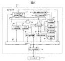
- FIG. 2 is a block diagram showing an internal configuration of the optical drive (information recording / reproducing apparatus) 10 in FIG.
- the optical drive 10 of this embodiment uses an optical disc (information recording medium) 1 that records and reproduces digital information using holography.
- the optical drive 10 is connected to the drive interface 117 of the library apparatus 100 via the input / output control circuit 90.
- recording data the data to be recorded is received from the drive interface 117 via the input / output control circuit 90.
- reproducing data the reproduced data is transmitted to the drive interface 117 via the input / output control circuit 90.
- the optical drive 10 includes a pickup 11, a reproduction reference light optical system 12, a cure optical system 13, a disk rotation angle detection optical system 14, and a rotation motor 50.
- the optical disk 1 can be rotated by the rotation motor 50. It has become.
- the pickup 11 emits reference light and signal light to the optical disc 1 and records data on the optical disc 1 using holography. Data to be recorded at this time is sent to the spatial light modulator in the pickup 11 by the controller 89 via the signal generation circuit 86, and the signal light is modulated by the spatial light modulator.
- the reference light emitted from the pickup 11 is generated by the reproduction reference light optical system 12 so as to generate a light wave in the direction opposite to that at the time of recording and enter the optical disc 1.
- the reproduction light reproduced by the reproduction reference light is detected by a photodetector in the pickup 11, and data is reproduced by the signal processing circuit 85.
- the irradiation time of the reference light and the signal light applied to the optical disc 1 is adjusted by controlling the opening / closing time of the shutter in the pickup 11 via the shutter control circuit 87 by the controller 89.
- the cure optical system 13 generates a light beam used for pre-cure and post-cure of the optical disc 1.
- Precure is a pre-process for irradiating a predetermined light beam in advance before irradiating the reference light and signal light to the desired position when data is recorded at the desired position in the optical disc 1.
- Post-cure is a post-process for irradiating a predetermined light beam after recording data at a desired position in the optical disc 1 so that additional recording cannot be performed at the desired position.
- the disk rotation angle detection optical system 14 detects the rotation angle of the optical disk 1.
- a signal corresponding to the rotation angle is detected by the disk rotation angle detection optical system 14, and the controller 89 uses the detected signal via the disk rotation motor control circuit 88. Then, the rotation angle of the optical disc 1 is controlled.
- the pickup 11 and the cure optical system 13 are provided with a mechanism capable of sliding the position in the radial direction of the optical disc 1, and position control is performed via an access control circuit 81.
- the light source drive circuit 82 supplies a predetermined light source drive current to the light sources in the pickup 11, the cure optical system 13, and the disk rotation angle detection optical system 14, and a light beam is emitted from each light source with a predetermined light amount. .
- the recording method using the principle of angle multiplexing of holography tends to have a very small tolerance for the deviation of the reference beam angle. Therefore, a mechanism for detecting the shift amount of the reference light angle is provided in the pickup 11 to control the reference light angle with high accuracy.
- a servo signal generation circuit 83 generates a servo control signal, and a servo mechanism for correcting the reference light angle deviation amount via the servo control circuit 84 is provided.
- the pickup 11, the cure optical system 13, and the disk rotation angle detection optical system 14 may be simplified by combining several optical system configurations or all optical system configurations into one.
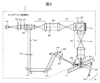
- FIG. 3 is a diagram illustrating the configuration of the pickup 11 and the operation during recording.
- the light beam emitted from the light source 301 passes through the collimator lens 302 and enters the shutter 303.
- the shutter 303 When the shutter 303 is open, after the light beam passes through the shutter 303, the optical ratio of the p-polarized light and the s-polarized light becomes a desired ratio by the optical element 304 composed of, for example, a half-wave plate.
- the light enters the PBS (polarization beam splitter) prism 305.
- PBS polarization beam splitter
- the light beam that has passed through the PBS prism 305 functions as signal light 306, and after the light beam diameter is expanded by the beam expander 308, the light beam passes through the phase mask 309, the relay lens 310, and the PBS prism 311 and passes through the spatial light modulator 312. Is incident on.
- the signal light to which information is added by the spatial light modulator 312 reflects the PBS prism 311 and propagates through the relay lens 313 and the spatial filter 314. Thereafter, the signal light is condensed on the optical disk 1 by the objective lens 315.
- the light beam reflected from the PBS prism 305 functions as reference light 307 and is set to a predetermined polarization direction according to recording or reproduction by the polarization direction conversion element 316, and then passes through mirrors 317 and 318 to be galvanomirrors. 319 is incident. Since the angle of the galvanometer mirror 319 can be adjusted by the actuator 320, the incident angle of the reference light incident on the optical disc 1 after passing through the lenses 321 and 322 can be set to a desired angle.
- the signal light and the reference light are incident on the optical disc 1 so as to overlap each other, whereby an interference fringe pattern (hologram) is formed in the medium, and data is recorded by writing this hologram on the medium.
- an interference fringe pattern hologram
- the incident angle of the reference light incident on the optical disc 1 can be changed by the galvanometer mirror 319, recording by angle multiplexing is possible.
- holograms corresponding to each reference light angle are referred to as “pages”, and a collection of “pages” angle-multiplexed in the same area. It will be called “book”.
- data is handled in units of pages, so one page of data can also be called a “data block”.
- FIG. 4 is a diagram illustrating the configuration of the pickup 11 and the operation during playback.
- the reference beam 307 is incident on the optical disc 1 as described above.
- the reproduction reference light optical system 12 reflects the light beam transmitted through the optical disc 1 by the galvano mirror 324 whose angle can be adjusted by the actuator 323, thereby generating the reproduction reference light.
- the reproduction light 306 reproduced by the reproduction reference light propagates through the objective lens 315, the relay lens 313, and the spatial filter 314. Thereafter, the reproduction light passes through the PBS prism 311 and enters the photodetector 325, and the recorded data can be reproduced.
- the photodetector 325 for example, an image sensor such as a CMOS image sensor or a CCD image sensor can be used, but other elements may be used as long as the page data can be reproduced.
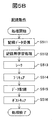
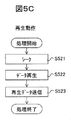
- FIG. 5A, FIG. 5B, and FIG. 5C are diagrams showing an overall flow of recording and reproducing operations in the optical drive 10. Here, recording / reproduction using holography will be described.
- FIG. 5A shows an operation flow for preparing for recording or reproduction after the optical disc 1 is inserted into the optical drive 10.
- the optical drive 10 determines whether the inserted disc is a hologram medium that records and reproduces digital information using holography (S501). If the optical disc 10 is determined to be a hologram medium as a result of disc discrimination, the optical drive 10 reads out media identification information (medium ID) provided on the optical disc (S502), and relates to information relating to the optical disc and various setting conditions during recording and reproduction. Get information.
- media ID media identification information
- FIG. 5B shows an operation flow for recording data on the optical disc 1 from the ready state.
- the signal generation circuit 86 When data to be recorded is received (S511), the signal generation circuit 86 generates two-dimensional data for recording corresponding to the data and sends it to the spatial light modulator 312 in the pickup 11. Further, various recording learning processes are performed to optimize the power of the light source 301 and the exposure time of the shutter 303 so that high quality data can be recorded on the optical disc (S512).
- the access control circuit 81 is controlled to perform a seek operation to position the pickup 11 and the cure optical system 13 at predetermined positions on the optical disc (S513).
- a predetermined region is pre-cured using the light beam emitted from the cure optical system 13 (S514), and data is recorded using the reference light and signal light emitted from the pickup 11 (S515). After recording the data, post cure is performed using the light beam emitted from the cure optical system 13 (S516). Data may be verified as necessary.
- FIG. 5C shows an operation flow for reproducing the data recorded on the optical disc 1 from the ready state.
- the access control circuit 81 is controlled to perform a seek operation, and the positions of the pickup 11 and the reproduction reference light optical system 12 are positioned at predetermined positions on the optical disk (S521).
- the reference light is emitted from the pickup 11, the data recorded on the optical disk is read (S522), and the reproduction data is generated and transmitted by the signal processing circuit 85 (S523).
- FIG. 6 is a block diagram of the signal generation circuit 86 (for recording) of the optical drive 10.
- the input / output control circuit 90 notifies the controller 89 that the input of user data has started.
- the controller 89 instructs the signal generation circuit 86 to record the data (data block) for one page input from the input / output control circuit 90.
- a processing command from the controller 89 is notified to the sub-controller 601 in the signal generation circuit 86 via the control line 608.
- the sub-controller 601 controls each signal processing circuit to perform the following operation via the control line 608.
- the memory control circuit 603 stores user data input from the input / output control circuit 90 via the data line 609 in the memory 602.
- Information relating to recording received from the controller 89 is stored in the memory 602 via the memory control circuit 603.
- the CRC calculation circuit 604 converts the user data into CRC (Cyclic Redundancy Check).
- the scramble circuit 605 scrambles the CRC-converted data by adding a pseudo random number data sequence
- the error correction encoding circuit 606 performs error correction encoding by adding a parity data sequence.
- the pickup interface circuit 607 reads out the error correction encoded data from the memory 602 in the order of the two-dimensional data on the spatial light modulator 312, adds a reference marker at the time of reproduction, and then stores the data in the pickup 11.
- the two-dimensional data is transferred to the spatial light modulator 312.
- FIG. 7 is a block diagram of the signal processing circuit 85 (for reproduction) of the optical drive 10.
- the controller 89 instructs the signal processing circuit 85 to reproduce the data (data block) for one page input from the pickup 11.
- a processing command from the controller 89 is notified to the sub-controller 701 in the signal processing circuit 85 via the control line 711.
- the sub-controller 701 controls each signal processing circuit to perform the following operation via the control line 711.
- the memory control circuit 703 stores image data input from the pickup 11 via the pickup interface circuit 710 in the memory 702 via the data line 712.
- the image position detection circuit 709 detects a marker from the image data stored in the memory 702 and extracts an effective data range.
- An image distortion correction circuit 708 performs distortion correction such as image inclination, magnification, and distortion using the detected marker, and converts the image data into the expected two-dimensional data size.
- the binarization circuit 707 binarizes each bit data of a plurality of bits constituting the size-converted two-dimensional data by determining “0” or “1”, and arranges the output of the reproduction data on the memory 702. Store.
- the error correction circuit 706 corrects an error included in each data string, and the scramble release circuit 705 cancels the scramble to which the pseudo random number data string is added, and then the CRC calculation circuit 704 causes an error in the user data on the memory 702. Check if it is included. Thereafter, user data is transferred from the memory 702 to the input / output control circuit 90.
- FIG. 8A and 8B are diagrams showing a data processing flow at the time of recording and at the time of reproduction.
- FIG. 8A shows a recording data processing flow in the signal generation circuit 86.
- the recording data is received by the input / output control circuit 90 (FIG. 5B, S511) and then converted into two-dimensional data on the spatial light modulator 312. Indicates processing.
- S801 When user data to be recorded on the optical disk is received (S801), each data string is converted to a CRC so that error detection during reproduction can be performed by dividing the data into a plurality of data strings (S802).
- the number of on-pixels is substantially equal to the number of off-pixels, and after performing scrambling to add a pseudo-random data sequence to the data sequence to prevent repetition of the same pattern (S803), Reed-Solomon so that error correction can be performed at the time of reproduction. Error correction coding such as codes is performed (S804).
- this data string is converted into M ⁇ N two-dimensional data, and is repeated for one page data (data block), thereby forming two-dimensional data for one page (S805).
- a marker serving as a reference in image position detection and image distortion correction during reproduction is added to the two-dimensional data configured as described above (S806), and the data is transferred to the spatial light modulator 312 (S807).
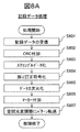
- FIG. 8B shows a reproduction data processing flow in the signal processing circuit 85, and shows processing from detection of two-dimensional data by the photodetector 325 to transmission of reproduction data to the input / output control circuit 90 (S523).
- the signal processing circuit 85 acquires the reproduction image data detected by the photodetector 325 (S811).
- An image position is detected with reference to a marker included in the image data (S812), and distortion such as inclination, magnification, and distortion of the image is corrected (S813).
- binarization processing is performed (S814), the marker is removed (S815), and two-dimensional data for one page is acquired (S816).
- error correction processing is performed (S817), and the parity data string is removed.
- descrambling processing is performed (S818), CRC error detection processing is performed and CRC parity is deleted (S819), and reproduction data is transmitted (S820).
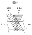
- FIGS. 9A and 9B are diagrams illustrating the relationship between the signal light and the reference light irradiated on the optical disc.
- the signal light 902 is a light beam collected by the objective lens 315, is incident on the optical disk 1 at a certain angle
- the reference light 901 is a parallel light beam
- the optical disk at an angle different from that of the signal light 902. 1 is incident.
- An interference pattern (hologram) between the incident reference light 901 and signal light 902 is recorded on the recording layer 900 of the optical disc 1.
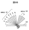
- FIG. 9B is a diagram in which the angle of the reference beam 901 is changed and incident.
- a plurality of interference fringes depending on the angle formed by the reference light 901 and the signal light 902 are formed in the same volume by changing the angle of the reference light 901 irradiated at the time of recording.
- the angle of the signal light 902 is ⁇ s
- the angle of the reference light 901 is changed stepwise from ⁇ 1 to ⁇ 7, whereby a plurality of interference fringes due to the reference light 901 and the signal light 902 are formed on the recording layer 900 of the optical disc 1. It is formed.
- each reference beam 901 having an angle ⁇ 1 to ⁇ 7 is irradiated to detect interference components due to interference fringes as signal light.
- interference fringes formed in the same volume are formed using the reference light angle as a parameter. For example, if the angle formed by the signal light and the reference light is in increments of 0.1 degrees from 40 degrees to 60 degrees, 200 kinds of angle multiplex recording can be realized, and 200 kinds of two-dimensional data (page, data block) are the same. Are recorded in a book having a volume of.
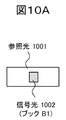
- FIG. 10A and 10B are diagrams showing the size and positional relationship between the reference light and the signal light at the center depth position of the optical disc, as viewed from the light irradiation side.
- FIG. 10A shows the sizes of the reference light 1001 and the signal light 1002 when recording one book (B1). Since the signal light 1002 is condensed in the medium, the reference light 1001 is parallel light. Therefore, the size of the signal light 1002 is smaller than the size of the reference light 1001 in the medium.
- the book B1 is formed according to the size of the signal light 1002 where the two intersect. When the recorded book B1 is reproduced, the book B1 is irradiated with the reference light 1001 to detect the reproduction light. This is the same when the book is inspected.
- FIG. 10B shows the positional relationship when recording four adjacent books B1 to B4.
- the four books are arranged in a straight line in the X direction.
- the four books are displayed while being shifted in the Y direction in order to distinguish each region.
- the four books are formed in order corresponding to the irradiation positions of the four signal lights 1002, 1004, 1006, and 1008.
- the position of the reference light corresponding to each book is arranged in the order of 1001, 1003, 1005, and 1007.
- the reference light irradiation range for one book overlaps the reference light irradiation range for the adjacent book.
- the range of the reference light 1001 of the book B1 partially overlaps the range of the reference light 1007 of the book B4 that is three books away.
- the reference light irradiation range overlaps with the reference light irradiation range of adjacent books, in other words, one reference light irradiation range includes a plurality of books.
- the inspection efficiency is improved by irradiating the reference light used for the inspection in units of a plurality of books. At that time, it is assumed that the deterioration phenomenon of the recorded book occurs in units of the reference light irradiation range, and one book is extracted from the irradiation range for inspection, and a part of a plurality of pages included in one book is checked. The page was extracted and inspected.
- the inspection method will be described in Examples.
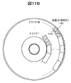
- FIG. 11A and FIG. 11B are diagrams showing an example of a book row arranged on an optical disc and an incident range of inspection light for inspecting the book row.
- FIG. 11A shows the signal light irradiation region at the center depth position of the medium, that is, the formation region of the book 1101.
- FIG. 11B shows an irradiation area of reference light irradiated as inspection light.
- the irradiation range by one inspection light (reference light) 1102 is the size of a range including three books. Therefore, by irradiating the inspection light (reference light) 1102 every three books instead of irradiating every book, the inspection of optical disks in the range of three books (inspection of deposits such as scratches and dust on the surface, Detection of a reproduction error) can be performed once. That is, the inspection light 1102 may be moved by a distance of three books, and the number of irradiation positions of the inspection light is smaller than the number of books formed on the optical disc.
- FIG. 12A and FIG. 12B are diagrams showing another example of a book placed on an optical disc and an incident range of inspection light for inspecting the book.
- the interval between the book 1201 and the inspection light 1202 is different (non-uniform), and a gap is provided between adjacent books.
- the inspection light (reference light) 1202 for each of a plurality (2 or 3) of books, the inspection of the optical disk in the range of the plurality of books can be performed at a time.
- the reason why the book interval is different is that the data capacity recorded on the optical disc varies depending on the characteristics of the optical disc, and the book interval is determined in accordance with this.
- the book interval and the address for irradiating the inspection light can be set according to the medium identification information (S502 in FIG. 5A) read when the optical disk is loaded.
- the inspection address set in this way is stored in the monitoring information storage unit 119 in association with the medium ID of the optical disc.
- FIG. 13 is a flowchart showing an optical disk inspection method.
- the entire recording area of the optical disc to be inspected is the inspection target.
- the data recording range of the optical disc is extracted from the medium identification information (S502 in FIG. 5A) read when the optical disc is loaded, and the inspection target area is set (S1301). Then, the irradiation intervals of the inspection light 1102 and 1202 are set as shown in FIG. 11B or FIG. 12B using the width of the reference light as inspection light and the interval of the book as parameters (S1302). Next, based on the inspection range and the irradiation interval of the inspection light, an inspection address in the optical disc is set and held in the monitoring information storage unit 119 (S1303).
- the inspection value at the inspection address of the optical disk for example, the data error rate is acquired (S1304), and compared with the error rate detection threshold Th1 (S1305).
- the detection threshold Th1 is a state in which deterioration of the quality of the optical disk proceeds and should be replaced with another optical disk, which will be described later.
- the inspection value is stored in the memory in the monitoring information storage unit 119 (S1309), and the inspection is terminated.
- the quality of the optical disc may be unreproducible in the library device during future playback. Therefore, an alert for data migration is presented (S1308), the inspection value is stored in the memory (S1309), and the inspection is terminated.
- the setting of the inspection address in S1303 will be specifically described. For example, in the configuration in which the reference beams 1001, 1003,... Are used as the inspection light as shown in FIG. If there is a fractional book in each track, it is set as an inspection address for additional inspection.
- the inspection address in the book is set to an inspection address of 10 pages or less instead of all pages.
- 10 pages or less for example, if the inspection object includes two pages where the angle between the signal light and the reference light is maximum and minimum, the inspection light incident range can be set wider, so the inspection accuracy is improved. Can be expected.
- the incident area of the inspection light is maximized, so that inspection can be performed more efficiently than other pages.
- the optical drive 10 can efficiently and accurately perform the quality inspection of the optical disc 1 according to the instruction from the library control unit 111. Further, if the result of the quality inspection is a threshold Th1 or more determined by the library apparatus, the library apparatus presents an alert. Thereby, the user or the administrator of the host computer can promptly replace the corresponding optical disk.
- the library apparatus 100 stores or manages a large number of optical disks, and all these optical disks must be inspected to ensure system reliability.
- Factors of quality deterioration in optical disks are due to aging deterioration of the recording material of the optical disk or the peripheral materials of the recording material (first factor), and due to light incident obstruction due to scratches or deposits on the light incident surface of the optical disk (second factor) ). Therefore, in order to efficiently inspect the optical disc, it is necessary to inspect the occurrence frequency or occurrence probability of these deterioration factors.
- Example 2 when the quality of the optical disk is the first factor, the material is aged, and the inspection cycle that is a standard for disk replacement is suitably set based on the quality deterioration characteristics due to the temperature environment.
- FIG. 14 is a diagram showing an example of the relationship between the storage period of the optical disc and the quality inspection value.
- the vertical axis is an inspection value such as an error rate, for example, and the reproduction limit Th2 is a state in which normal reproduction is impossible.
- the period until the quality degradation of the optical disk reaches the reproduction limit Th2 varies depending on the temperature environment, and it can be said that the higher the temperature environment, the faster the degradation.
- a detection threshold Th1 is provided for determining that the quality deterioration has progressed and that the disk needs to be replaced.
- the optical disk quality inspection timing must be performed in a period between the detection threshold Th1 and the reproduction limit Th2. That is, referring to the deterioration characteristics of FIG. 14, the amount of aging deterioration is predicted based on the elapsed time from the previous inspection, and the inspection cycle is set so as not to exceed the regeneration limit Th2.
- an inspection cycle a shorter than the period A is set in consideration of the safety factor for the period A from reaching the detection threshold Th1 to reaching the regeneration limit Th2.
- an inspection cycle b shorter than the period B is set in consideration of the safety factor.
- the inspection periods a and b are different depending on the temperature environment, and in this case, a ⁇ b.
- FIG. 15 is an example of an inspection cycle table showing the relationship between the storage temperature and the inspection cycle.
- An inspection cycle for performing a quality inspection is set for each storage temperature so that the regeneration limit is not exceeded at the next inspection timing.
- the set inspection cycle is stored in the monitoring information storage unit 119 as a table.
- the library apparatus refers to this table, assigns an appropriate inspection period according to the environmental temperature, and performs the inspection.
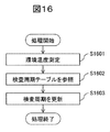
- FIG. 16 is a diagram showing a processing flow for determining the inspection cycle.
- the library control unit 111 measures the environmental temperature with the thermometer 121 (S1601).
- the library control unit 111 refers to the inspection cycle table stored in the monitoring information storage unit 119 via the library monitoring unit 118, reads the inspection cycle corresponding to the temperature measurement value (S1602), and updates subsequent inspection cycles. (S1603).
- the quality inspection for the aging deterioration of the material can be inspected at an appropriate timing, and the optical disk can be prevented from suddenly causing a reproduction error. Further, by appropriately setting the inspection timing, it is not necessary to carry out useless inspection work, and the operating efficiency of the apparatus can be improved.
- the second cause of quality degradation of optical disks is due to light incidence obstruction due to scratches or deposits on the light incident surface.
- quality degradation is affected by the dust environment at the installation location of the library apparatus 100 and the number of times the optical disk 1 is transported.
- the dust environment is particularly susceptible to deposits such as scratches and dust in the vicinity of the optical disk holding part of the changer mechanism 112 that contacts the surface of the optical disk in the library apparatus 100 and the optical disk holding part of the data disk storage part 113. Therefore, the installation environment is managed and periodic inspection is performed. Also in this case, the inspection cycle is set based on the dust environment of the library apparatus so that the regeneration limit is not exceeded at the next inspection timing.
- the dust environment measuring device is omitted in the present apparatus configuration, a dust environment measuring device may be mounted in the same manner as the thermometer, and the inspection cycle may be changed based on the inspection result.
- the influence of accidental scratches and dust adhering to the optical disk transport of the library device depends on the operation status of the library device, so reliable and stable data can be obtained only by periodic inspection. Is difficult. Therefore, the number of times each optical disk is conveyed by the changer mechanism 112 of the library apparatus 100 is checked, and the inspection is performed when the predetermined number of times is reached.
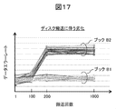
- FIG. 17 is a diagram showing the relationship between the number of optical disk transports and the data error rate.
- the data error rate inspected at the time of the first transport that is, the recording
- the data error rate inspected after the transport of 100 times, 200 times, and 1000 times are shown.
- the inspection objects are two adjacent books B1 and B2 recorded on the same optical disc, and are the results of inspection by extracting 20 pages from each book.
- Book B1 there is no change in the data error rate measured at the time of the first transfer (recording) and after the transfer of 1000 times
- Book B2 the data error rate is between 100 and 200 times. Has deteriorated significantly.
- FIG. 18 is an example of a table showing the number of times of conveyance that is the inspection timing of the optical disc.
- the number of times the optical disk to be subjected to the quality inspection is set and stored in the monitoring information storage unit 119.
- the number of conveyances to be inspected is set to 100 times, 200 times, 500 times,...
- the library apparatus 100 inspects each optical disc in response to the number of conveyance times described in the table.
- FIG. 19 is a diagram showing a processing flow for determining the inspection timing.
- the library control unit 111 accumulates and acquires the number of operations of the changer mechanism 112 when transporting each optical disc 1 (S1901).
- the optical drive 10 acquires the ID of the conveyed optical disk 1 (S1902).
- the library control unit 111 stores the ID of each optical disk and the number of conveyances in the monitoring information storage unit 119 via the library monitoring unit 118 (S1903).
- the library control unit 111 reads the ID of each optical disk and the number of conveyances stored in the monitoring information storage unit 119, and compares the number with the number of conveyances set in the table to determine the necessity of inspection (S1904).
- the inspection time of the book can be reduced to the number of pages existing in the book, for example, 1/200.
- the reference light 1001 and 1007 are irradiated as inspection light to each book, thereby reading out the influence of scratches and dust depending on the disk surface over three adjacent books. Quality (data error rate, etc.). Therefore, the inspection time can be reduced to 1/600 by setting the inspection in units of three books and setting the inspection page in the book to 1/200.
- it took 81.7 days to check the total number of 1000 optical discs with 8 recording / playback devices installed in the library device. 41.7 days x (1/3) x (1/200) 1.7 hours can be significantly shortened, so the operation is not dominant in the operation of the equipment, and the data reliability is efficient and highly accurate. Can be secured.
- the inspection accuracy decreases due to the shortening of the inspection time, there is a possibility of making an erroneous determination. Therefore, in the measurement of the optical drive 10, it is possible to inspect with higher accuracy by inspecting a page that becomes a plurality of data blocks in consideration of variation and calculating an average value thereof. For example, by calculating 10 pages in a book and calculating an average value, the dispersion that causes measurement variation can be reduced to 1/10. Although it depends on the detection accuracy of the optical drive 10, it is sufficient if the data error rates of the book B1 and the book B2 in FIG. 17 can be clearly separated and the effect of reducing the dispersion of measurement variation to 1/10 is sufficient. It can be judged as inspection accuracy.
- the third embodiment it is possible to perform inspection at an appropriate timing with respect to light incidence inhibition due to scratches or adhering matter on the light incident surface of the optical disc, particularly quality degradation caused by the number of times the optical disc is transported, and the optical disc is reproduced suddenly An error can be avoided. Further, by appropriately setting the inspection timing, it is not necessary to carry out useless inspection work, and the operating efficiency of the apparatus can be improved.
- this invention is not limited to each above-mentioned Example, Various modifications are included.
- an optical disc, particularly a hologram recording medium is used as an information recording medium.
- a method of multiplex recording data on the same area of the recording medium or when irradiating inspection light over a plurality of data areas The same applies.
- the definitions of “page” and “book” used in the hologram recording method are extended and interpreted.
- the components, functions, processing units, processing means, etc. in the above embodiments may be realized in hardware by designing a part or all of them, for example, with an integrated circuit.
- Each of the above-described configurations, functions, and the like may be realized by software by interpreting and executing a program that realizes each function by the processor.
- the control lines and information lines indicate what is considered necessary for the explanation, and not all the control lines and information lines on the product are necessarily shown. Actually, it may be considered that almost all the components are connected to each other.
Landscapes
- Optical Recording Or Reproduction (AREA)
Abstract
ライブラリ装置において、データは複数のページに分割され、光ドライブにより光ディスクの所定の記録領域ごとに複数のページが多重されてブックとして記録され、ブックは光ディスク上に配列して形成されている。ライブラリ制御部は光ドライブに対し、1つの記録領域でのデータを検査するために、光ディスクに配列された複数のブックを含む範囲に検査光を照射させ、検査光が照射された複数のブックのうち1つのブックのみを再生させて信号の品質を評価する。さらに次の記録領域で検査を行うため、検査光の照射位置を光ディスクに配列された複数のブック分の距離だけ移動させて次の検査を行うことで、光ディスクに照射する検査光の照射位置の数を光ディスクに記録されたブック数よりも少なくして、記録した全領域のデータを検査する。
Description
本発明は、複数の情報記録媒体を用いたライブラリ装置、および情報記録媒体の検査方法に関する。
本発明に関する背景技術として、例えば特許文献1に記載の技術がある。特許文献1には「光ディスク101のデータ領域200にユーザデータUを記録する際に、テスト領域210に信号レベルが基準値よりも小さい成分を含むテスト信号Tを記録しておく。所定の時間経過した時点で、テスト領域のテスト信号Tを再生し、その評価結果からユーザデータUの品質劣化を推定する。または、データ領域に200にユーザデータUを記録または再生する毎に、テスト領域210にテスト信号Tを繰り返して記録または再生する。所定のタイミングで、テスト領域のテスト信号Tを再生し、その評価結果からユーザデータUの品質劣化を推定する。」と記載されている。
上記特許文献1には、記録品質の経年劣化を短時間で検査するために、検査領域を限定することが明記されている。検査領域を限定することより、検査時間を短縮することができるが、一方で全てのデータを検査できないため、劣化が存在しても検査漏れが発生する恐れがある。
本発明の目的は、記録した全領域のデータを検査精度を下げずに短時間で検査を実施するライブラリ装置および情報記録媒体の検査方法を提供することである。
上述の課題を解決するために、請求の範囲に記載の構成を採用する。その一例を挙げるならば、本発明のライブラリ装置は、情報記録再生装置により複数の情報記録媒体にデータを記録再生するものであって、情報記録媒体に記録したデータの品質を評価するときの検査アドレスを格納する監視情報格納部と、情報記録再生装置に対し、監視情報格納部に格納した検査アドレスに基づき情報記録媒体の検査を指示するライブラリ制御部と、を備える。前記データは情報記録再生装置により、複数のデータブロック(以下、ページと呼ぶ)に分割され、情報記録媒体の所定の記録領域ごとに複数のページが多重されて集合体(以下、ブックと呼ぶ)として記録され、前記ブックは情報記録媒体上に配列して形成されたものである。ライブラリ制御部は情報記録再生装置に対し、1つの記録領域でのデータを検査するために、情報記録媒体に配列された複数のブックを含む範囲に検査光を照射させ、検査光が照射された複数のブックのうち1つのブックのみを再生させて信号の品質を評価する。さらに次の記録領域で検査を行うため、検査光の照射位置を情報記録媒体に配列された複数のブック分の距離だけ移動させて次の検査を行うことで、情報記録媒体に照射する検査光の照射位置の数を情報記録媒体に記録されたブック数よりも少なくして、記録した全領域のデータを検査することを特徴とする。
本発明によれば、ライブラリ装置に用いる複数の情報記録媒体を高精度にかつ効率良く検査することができる。
以下、本発明の実施例について図面を用いて説明する。情報記録媒体として光ディスク、特にホログラム記録媒体を用いる場合について説明する。
図1は、本発明のライブラリ装置の一構成例を示すブロック図である。ライブラリ装置100は、ライブラリ制御部111と、チェンジャー機構112と、光ディスク1を複数枚収納するデータディスク格納部113と、予備ディスク格納部114と、廃棄ディスク格納部115と、ホストインタフェース116と、ドライブインタフェース117と、ライブラリ監視部118と、監視情報格納部119と、温度計121と、光ドライブ選択部122と、複数の光ドライブ(情報記録再生装置)10で構成される。
ライブラリ装置100は、ホストインタフェース116を介してホストコンピュータ120と接続され、データの記録や再生といった各種のコマンドと記録するデータを受信し、コマンドの実行結果と再生したデータを送信する。
データディスク格納部113は複数のスロットを備えており、各スロットには1枚ずつ光ディスク1を収納することができる。チェンジャー機構112は、データディスク格納部113と光ドライブ10との間で光ディスク1を搬送する機構である。
予備ディスク格納部114は、ライブラリ装置100の通常の動作では用いられない。ただし、検査によって光ディスク1の性能が劣化していると判定された場合に、予備ディスク格納部114からデータディスク格納部113に光ディスク1を供給する。廃棄ディスク格納部115は、ライブラリ装置100がディスク検査において劣化していると判定した光ディスク1を格納する。
ライブラリ制御部111はライブラリ装置100の動作全般を制御する。データディスク格納部113に格納された光ディスク1へのデータアクセスの際、つまり光ディスク1に記録されたデータの再生時、もしくは光ディスク1へのデータ記録時には、チェンジャー機構112を動作させて、データディスク格納部113から所定の光ディスク1を取り出し、データアクセスを行う光ドライブ10へ搬送してロードする。
またライブラリ制御部111は、光ドライブ選択部122を動作させて、ドライブインタフェース117を介して接続されている光ドライブ10から使用する光ドライブ10を選択し、選択した光ドライブ10との間で記録や再生といった各種のコマンドやデータの送受信を行う。
ライブラリ監視部118は光ディスク1の状態管理を実施し、監視情報格納部119は、ライブラリ監視部118が検出した各光ディスク1に記録されているデータの管理情報、各光ディスク1の記録品質(検査結果)、各光ディスク1の検査アドレスや検査周期などを保持している。温度計121はライブラリ装置100の内部の環境温度を計測し、ライブラリ制御部111は環境温度の計測結果を監視する。
図2は、図1における光ドライブ(情報記録再生装置)10の内部構成を示すブロック図である。本実施例の光ドライブ10は、ホログラフィを利用してデジタル情報を記録再生する光ディスク(情報記録媒体)1を用いている。光ドライブ10は、入出力制御回路90を介してライブラリ装置100のドライブインタフェース117と接続されている。データを記録する場合には、記録するデータをドライブインタフェース117から入出力制御回路90を介して受信する。データを再生する場合には、再生したデータを入出力制御回路90を介してドライブインタフェース117に送信する。
光ドライブ10は、ピックアップ11、再生用参照光光学系12、キュア光学系13、ディスク回転角度検出用光学系14、及び回転モータ50を備えており、光ディスク1は回転モータ50によって回転可能な構成となっている。
ピックアップ11は、参照光と信号光を光ディスク1に出射してホログラフィを利用してデータを光ディスク1に記録する。この際記録するデータは、コントローラ89によって信号生成回路86を介してピックアップ11内の空間光変調器に送られ、信号光は空間光変調器によって変調される。
光ディスク1に記録したデータを再生する場合は、再生用参照光光学系12により、ピックアップ11から出射された参照光を記録時とは逆向きの光波を生成して光ディスク1に入射させる。再生用参照光によって再生された再生光は、ピックアップ11内の光検出器によって検出され、信号処理回路85によってデータが再生される。
光ディスク1に照射する参照光と信号光の照射時間は、コントローラ89によりシャッタ制御回路87を介しピックアップ11内のシャッタの開閉時間を制御することで調整する。キュア光学系13は、光ディスク1のプリキュアおよびポストキュアに用いる光ビームを生成する。プリキュアとは、光ディスク1内の所望の位置にデータを記録する際、所望位置に参照光と信号光を照射する前に予め所定の光ビームを照射する前工程である。ポストキュアとは、光ディスク1内の所望の位置にデータを記録した後、該所望の位置に追記不可能とするために所定の光ビームを照射する後工程である。
ディスク回転角度検出用光学系14は、光ディスク1の回転角度を検出する。光ディスク1を所定の回転角度に調整する場合は、ディスク回転角度検出用光学系14によって回転角度に応じた信号を検出し、コントローラ89は検出された信号を用いてディスク回転モータ制御回路88を介して光ディスク1の回転角度を制御する。また、ピックアップ11やキュア光学系13は、光ディスク1の半径方向に位置をスライドできる機構が設けられており、アクセス制御回路81を介して位置制御が行われる。光源駆動回路82は、ピックアップ11、キュア光学系13、ディスク回転角度検出用光学系14内の光源に所定の光源駆動電流を供給し、各々の光源からは所定の光量で光ビームが出射される。
ホログラフィの角度多重の原理を利用した記録方式は、参照光角度のずれに対する許容誤差が極めて小さくなる傾向がある。従って、ピックアップ11内に、参照光角度のずれ量を検出する機構を設けて、参照光角度を高精度に制御する。そのため、サーボ信号生成回路83にてサーボ制御用の信号を生成し、サーボ制御回路84を介して参照光角度のずれ量を補正するためのサーボ機構を備える。
なお、ピックアップ11、キュア光学系13、ディスク回転角度検出用光学系14は、いくつかの光学系構成または全ての光学系構成を1つに纏めて簡素化しても構わない。
図3は、ピックアップ11の構成と記録時の動作を説明する図である。光源301を出射した光ビームはコリメートレンズ302を通過し、シャッタ303に入射する。シャッタ303が開いている時は、光ビームはシャッタ303を通過した後、例えば2分の1波長板などで構成される光学素子304によってp偏光とs偏光の光量比が所望の比になるように偏光方向が制御された後、PBS(偏光ビームスプリッタ)プリズム305に入射する。
PBSプリズム305を透過した光ビームは、信号光306として働き、ビームエキスパンダ308によって光ビーム径が拡大された後、位相マスク309、リレーレンズ310、PBSプリズム311を透過して空間光変調器312に入射する。
空間光変調器312によって情報が付加された信号光は、PBSプリズム311を反射し、リレーレンズ313ならびに空間フィルタ314を伝播する。その後、信号光は対物レンズ315によって光ディスク1に集光する。
一方、PBSプリズム305を反射した光ビームは参照光307として働き、偏光方向変換素子316によって記録時または再生時に応じて所定の偏光方向に設定された後、ミラー317、318を経由し、ガルバノミラー319に入射する。ガルバノミラー319はアクチュエータ320によって角度を調整可能なため、レンズ321、322を通過した後に光ディスク1に入射する参照光の入射角度を、所望の角度に設定することができる。
このように光ディスク1に対し、信号光と参照光とを互いに重ね合うように入射させることで、媒体内には干渉縞パターン(ホログラム)が形成され、このホログラムを媒体に書き込むことでデータを記録する。また、ガルバノミラー319によって光ディスク1に入射する参照光の入射角度を変化させることができるため、角度多重による記録が可能である。
以降、同じ媒体領域に参照光角度を変えて記録されたホログラムにおいて、1つ1つの参照光角度に対応したホログラムを「ページ」と呼び、同領域に角度多重された「ページ」の集合体を「ブック」と呼ぶことにする。なお、ホログラム記録ではデータをページ単位で扱うことから、1ページのデータは「データブロック」とも呼ぶことができる。
図4は、ピックアップ11の構成と再生時の動作を説明する図である。記録したデータを再生する場合は、前述したように参照光307を光ディスク1に入射する。そして、光ディスク1を透過した光ビームを、再生用参照光光学系12において、アクチュエータ323によって角度調整可能なガルバノミラー324にて反射させることで、その再生用参照光を生成する。
この再生用参照光によって再生された再生光306は、対物レンズ315、リレーレンズ313ならびに空間フィルタ314を伝播する。その後、再生光はPBSプリズム311を透過して光検出器325に入射し、記録したデータを再生することができる。光検出器325としては例えばCMOSイメージセンサーやCCDイメージセンサーなどの撮像素子を用いることができるが、ページデータを再生可能であれば他の素子でも構わない。
図5A、図5B、図5Cは、光ドライブ10における記録、再生動作の全体フローを示す図である。ここでは、ホログラフィを利用した記録再生について説明する。
図5Aは、光ドライブ10に光ディスク1を挿入した後、記録または再生の準備を行う動作フローを示す。ディスクを挿入すると光ドライブ10は、挿入されたディスクがホログラフィを利用してデジタル情報を記録再生するホログラム媒体であるかどうかディスク判別を行う(S501)。ディスク判別の結果、ホログラム媒体であると判断されると、光ドライブ10は光ディスクに設けられた媒体識別情報(媒体ID)を読み出し(S502)、光ディスクに関する情報や、記録再生時における各種設定条件に関する情報を取得する。
その後、媒体識別情報に応じた各種調整やピックアップ11に関わる学習処理を行い(S503)、次に記録可能な領域(アドレス)を判定する(S504)。以上により、光ドライブ10は、記録または再生の準備が完了する(S505)。
図5Bは、準備完了状態から光ディスク1にデータを記録する動作フローを示す。記録するデータを受信すると(S511)、信号生成回路86は、該データに応じた記録用2次元データを生成してピックアップ11内の空間光変調器312に送る。また、光ディスクに高品質のデータを記録できるように、例えば光源301のパワーやシャッタ303の露光時間の最適化のため、各種記録用学習処理を行う(S512)。アクセス制御回路81を制御してシーク動作を行い、ピックアップ11ならびにキュア光学系13の位置を光ディスクの所定の位置に位置付けする(S513)。キュア光学系13から出射する光ビームを用いて所定の領域をプリキュアし(S514)、ピックアップ11から出射する参照光と信号光を用いてデータを記録する(S515)。データを記録した後は、キュア光学系13から出射する光ビームを用いてポストキュアを行う(S516)。必要に応じてデータをベリファイしても構わない。
図5Cは、準備完了状態から光ディスク1に記録したデータを再生する動作フローを示す。アクセス制御回路81を制御してシーク動作を行い、ピックアップ11ならびに再生用参照光光学系12の位置を光ディスクの所定の位置に位置付けする(S521)。ピックアップ11から参照光を出射し、光ディスクに記録されたデータを読み出し(S522)、信号処理回路85により再生データを生成して送信する(S523)。
以下、記録時と再生時のデータ処理について説明する。まず、記録時は信号生成回路86にて、再生時は信号処理回路85にてデータ処理を行う。
図6は、光ドライブ10の信号生成回路86(記録用)のブロック図である。入出力制御回路90にユーザデータの入力が開始されると、入出力制御回路90はコントローラ89にユーザデータの入力が開始されたことを通知する。コントローラ89は本通知を受け、信号生成回路86に入出力制御回路90から入力される1ページ分のデータ(データブロック)を記録処理するよう命ずる。コントローラ89からの処理命令は制御用ライン608を経由し、信号生成回路86内のサブコントローラ601に通知される。本通知を受けサブコントローラ601は、制御用ライン608を介して各信号処理回路に以下の動作を行うように制御する。
先ずメモリ制御回路603は、データライン609を介して入出力制御回路90から入力されるユーザデータをメモリ602に格納する。また、コントローラ89より受信した記録に関わる情報は、メモリ制御回路603を経由してメモリ602に格納する。メモリ602に格納したユーザデータおよび記録に関わる情報の量がある一定量に達すると、CRC演算回路604はユーザデータをCRC(Cyclic Redundancy Check)化する。スクランブル回路605は、CRC化したデータに擬似乱数データ列を加えるスクランブル化を施し、誤り訂正符号化回路606はパリティデータ列を加える誤り訂正符号化を行う。最後に、ピックアップインターフェース回路607は、メモリ602から誤り訂正符号化したデータを空間光変調器312上の2次元データの並び順で読み出し、再生時に基準となるマーカーを付加した後、ピックアップ11内の空間光変調器312に2次元データを転送する。
図7は、光ドライブ10の信号処理回路85(再生用)のブロック図である。ピックアップ11内の光検出器325が画像データを検出すると、コントローラ89は信号処理回路85に、ピックアップ11から入力される1ページ分のデータ(データブロック)を再生処理するよう命ずる。コントローラ89からの処理命令は制御用ライン711を経由し、信号処理回路85内のサブコントローラ701に通知される。本通知を受けサブコントローラ701は、制御用ライン711を介して各信号処理回路に以下の動作を行うように制御する。
先ずメモリ制御回路703は、ピックアップ11からピックアップインターフェース回路710を経由して入力される画像データを、データライン712を介してメモリ702に格納する。メモリ702に格納されたデータがある一定量に達すると、画像位置検出回路709は、メモリ702に格納された画像データ内からマーカーを検出して有効データ範囲を抽出する。画像歪み補正回路708は、検出されたマーカーを用いて画像の傾き・倍率・ディストーションなどの歪み補正を行い、画像データを期待される2次元データのサイズに変換する。2値化回路707は、サイズ変換された2次元データを構成する複数ビットの各ビットデータを、“0”、“1”判定して2値化し、メモリ702上に再生データの出力の並びで格納する。誤り訂正回路706は各データ列に含まれる誤りを訂正し、スクランブル解除回路705は擬似乱数データ列が加えられたスクランブルを解除した後、CRC演算回路704でメモリ702上のユーザデータ内に誤りが含まれないかを確認する。その後、入出力制御回路90にメモリ702からユーザデータを転送する。
図8Aと図8Bは、記録時と再生時のデータ処理フローを示す図である。
図8Aは信号生成回路86での記録データ処理フローを示し、入出力制御回路90において記録データを受信(図5B、S511)した後、空間光変調器312上の2次元データに変換するまでの処理を示す。光ディスクに記録するユーザデータを受信すると(S801)、複数のデータ列に分割、再生時エラー検出が行えるように各データ列をCRC化する(S802)。そして、オンピクセル数とオフピクセル数をほぼ等しくし、同一パターンの繰り返しを防ぐためデータ列に擬似乱数データ列を加えるスクランブルを施した後(S803)、再生時エラー訂正が行えるようにリード・ソロモン符号等の誤り訂正符号化を行う(S804)。次に、このデータ列をM×Nの2次元データに変換し、それを1ページデータ(データブロック)分繰返すことで1ページ分の2次元データを構成する(S805)。このように構成した2次元データに対して再生時の画像位置検出や画像歪補正での基準となるマーカーを付加し(S806)、空間光変調器312にデータを転送する(S807)。
図8Aは信号生成回路86での記録データ処理フローを示し、入出力制御回路90において記録データを受信(図5B、S511)した後、空間光変調器312上の2次元データに変換するまでの処理を示す。光ディスクに記録するユーザデータを受信すると(S801)、複数のデータ列に分割、再生時エラー検出が行えるように各データ列をCRC化する(S802)。そして、オンピクセル数とオフピクセル数をほぼ等しくし、同一パターンの繰り返しを防ぐためデータ列に擬似乱数データ列を加えるスクランブルを施した後(S803)、再生時エラー訂正が行えるようにリード・ソロモン符号等の誤り訂正符号化を行う(S804)。次に、このデータ列をM×Nの2次元データに変換し、それを1ページデータ(データブロック)分繰返すことで1ページ分の2次元データを構成する(S805)。このように構成した2次元データに対して再生時の画像位置検出や画像歪補正での基準となるマーカーを付加し(S806)、空間光変調器312にデータを転送する(S807)。
図8Bは信号処理回路85での再生データ処理フローを示し、光検出器325で2次元データを検出後、入出力制御回路90に再生データを送信(S523)するまでの処理を示す。信号処理回路85は、光検出器325で検出された再生画像データを取得する(S811)。この画像データに含まれるマーカーを基準に画像位置を検出し(S812)、画像の傾き・倍率・ディストーションなどの歪みを補正する(S813)。さらに2値化処理を行い(S814)、マーカーを除去することで(S815)、1ページ分の2次元データを取得する(S816)。このようにして得られた2次元データを複数のデータ列に変換した後、誤り訂正処理を行い(S817)、パリティデータ列を取り除く。次にスクランブル解除処理を施し(S818)、CRCによる誤り検出処理を行ってCRCパリティを削除した後に(S819)、再生データの送信を行う(S820)。
次に、光ディスク上での多重記録と記録されたデータの再生(検査)方法について説明する。
図9Aと図9Bは、光ディスクに照射する信号光と参照光の関係を示す図である。図9Aにおいて、信号光902は対物レンズ315で集光された光束であり、光ディスク1に対して一定の角度で入射し、参照光901は平行な光束であり、信号光902と異なる角度で光ディスク1に入射する。入射した参照光901と信号光902との干渉パターン(ホログラム)が、光ディスク1の記録層900に記録される。
図9Aと図9Bは、光ディスクに照射する信号光と参照光の関係を示す図である。図9Aにおいて、信号光902は対物レンズ315で集光された光束であり、光ディスク1に対して一定の角度で入射し、参照光901は平行な光束であり、信号光902と異なる角度で光ディスク1に入射する。入射した参照光901と信号光902との干渉パターン(ホログラム)が、光ディスク1の記録層900に記録される。
図9Bは、参照光901の角度を変えて入射させた図である。ホログラムディスクおける角度多重方式では、記録時に照射する参照光901の角度を複数通り変化させることにより、参照光901と信号光902のなす角に依存した複数通りの干渉縞が同一体積内に形成される。ここでは、信号光902の角度をθsとし、参照光901の角度をθ1からθ7まで段階的に変えることによって、各参照光901と信号光902による複数の干渉縞が光ディスク1の記録層900に形成される。再生時には、角度θ1からθ7の各参照光901を照射することにより、干渉縞による干渉成分を信号光として検出する。角度多重方式では、同一体積内に形成される干渉縞は参照光角度をパラメータとして形成される。例えば、信号光と参照光の成す角が40度から60度まで0.1度刻みとすれば、200通りの角度多重記録が実現でき、200通りの2次元データ(ページ、データブロック)が同一の体積であるブック内に多重記録される。
図10Aと図10Bは、光ディスクの中心深さ位置での参照光と信号光のサイズと位置関係を示す図で、光照射側から見た図である。図10Aは1個のブック(B1)を記録するときの参照光1001と信号光1002のサイズを示す。信号光1002は媒体内で集光されているのに対し、参照光1001は平行光となっているので、媒体内では信号光1002のサイズは参照光1001のサイズより小さくなっている。ブックB1は両者が交差するほぼ信号光1002の大きさに従って形成される。記録されたブックB1を再生するときは、参照光1001をブックB1に照射して再生光を検出するが、これはブックを検査するときも同様である。
また図10Bは、隣接する4個のブックB1~B4を記録するときの位置関係を示す。4個のブックはX方向に直線状に配列されるが、図では各領域を区別するために、Y方向にずらして表示している。4個のブックは、4通りの信号光1002、1004、1006、1008の照射位置に対応して順番に形成される。各ブックに対応する参照光の位置は、1001、1003、1005、1007の順番に配置される。これから分かるように、1つのブックに対する参照光の照射範囲は、これに隣接するブックに対する参照光の照射範囲と重複している。図10Bの場合には、ブックB1の参照光1001の範囲は、3ブック離れたブックB4の参照光1007の範囲と一部が重複している。
本発明では、参照光照射範囲が隣接するブックの参照光照射範囲と重複すること、言い換えれば、1つの参照光の照射範囲には複数のブックが含まれることに注目する。そして、検査に用いる参照光を複数ブック単位で照射することで、検査効率を向上させるようにした。その際、記録されたブックの劣化現象は参照光の照射範囲を単位に発生すると想定し、照射範囲から1つのブックを抽出して検査し、また1つのブックに含まれる複数のページから一部のページを抽出して検査するようにした。以下、その検査方法について実施例で説明する。
図11Aと図11Bは、光ディスク上に配置するブック列と、これを検査する検査光の入射範囲の一例を示す図である。図11Aは、媒体の中心深さ位置での信号光照射領域、すなわちブック1101の形成領域を示す。光ディスク1の各半径において、接線方向にブックが配列するトラックがあり、トラック数(ここでは1~60)だけブック列が円周状に敷き詰められている。
一方図11Bは、検査光として照射する参照光の照射領域を示す。図11Bにおいては、1回の検査光(参照光)1102による照射範囲は、3ブックを含む範囲の大きさになっている。そのため、1ブック毎に照射するのではなく、3ブック毎に検査光(参照光)1102を照射することによって、3ブックの範囲の光ディスクの検査(表面の傷や埃などの付着物の検査、再生エラーの検出)を1回で行うことが可能となる。すなわち、検査光1102の移動は3ブック分の距離でよいことになり、検査光の照射位置の数は光ディスク上に形成されているブックの数より少ない。
図12Aと図12Bは、光ディスク上に配置するブックと、これを検査する検査光の入射範囲の他の例を示す図である。この例では、ブック1201および検査光1202の間隔が異なり(不均一)、また隣接するブックの間に隙間を設けている。この場合も、複数(2または3)ブック毎に検査光(参照光)1202を照射することによって、複数ブックの範囲の光ディスクの検査を1回で行うことができる。なお、ブック間隔が異なる理由は、光ディスクに記録するデータ容量は光ディスクの特性により異なり、これに合わせてブックの間隔を決定するからである。また、ブックの間隔および検査光を照射するアドレスは、光ディスクのローディング時に読み出す媒体識別情報(図5AのS502)に応じて、設定することができる。このように設定した検査アドレスは光ディスクの媒体IDと対応させて監視情報格納部119に格納しておく。
図13は、光ディスクの検査方法を示すフローチャートである。全ユーザデータの信頼性を確保するため、特に傷や付着物などの光入射阻害要因を正しく判定するためには、検査対象である光ディスクの全記録領域を検査対象とする。
光ディスクのローディング時に読み出す媒体識別情報(図5AのS502)から、当該光ディスクのデータ記録範囲を抽出し、検査対象領域を設定する(S1301)。そして、検査光となる参照光の幅とブックの間隔をパラメータとして、図11Bもしくは図12Bのように検査光1102,1202の照射間隔を設定する(S1302)。次に、検査範囲と検査光の照射間隔に基づいて、光ディスク内の検査アドレスを設定して監視情報格納部119に保持する(S1303)。
光ディスクの検査アドレスにおける検査値、例えばデータエラーレートなどを取得し(S1304)、エラーレートの検出閾値Th1との比較を行う(S1305)。検出閾値Th1は、光ディスクの品質劣化が進行し、他の光ディスクと交換すべき状態のことであり、これについては後述する。比較の結果、閾値Th1を下回った場合は検査値を監視情報格納部119内のメモリに格納し(S1309)、検査を終了する。
比較の結果、エラーレートが閾値Th1以上の場合は、エラーレートが悪化した原因が当該光ディスクではなく使用した光ドライブにあることも考えられる。そこで、記録再生性能が確認済みの他の光ドライブを用いて再検査を実施する(S1306)。そして、検査値を再度閾値Th1と比較する(S1307)。比較の結果、閾値Th1を下回った場合は検査値をメモリに格納し(S1309)、検査を終了する。
再検査の結果においても閾値Th1以上の場合には、当該光ディスクの品質が当該ライブラリ装置において、今後の再生時に再生不可能になる可能性がある。そこで、データ移行のアラートを提示し(S1308)、検査値をメモリに格納し(S1309)、検査を終了する。
ここで、S1303の検査アドレスの設定について具体的に説明する。例えば、図10Bのような参照光1001、1003、・・・を検査光とする構成では、3ブック毎に検査をすればよいので、3ブック毎に検査アドレスを設定する。各トラックにおいて端数のブックがある場合は、追加検査のための検査アドレスとして設定する。
さらには、ブック内の検査アドレスは、全ページではなく例えば10ページ以下の検査アドレスを設定する。この10ページ以下には、例えば信号光と参照光のなす角度が最大および最小となる2つのページを含めて検査対象とすれば、検査光の入射範囲をより幅広く設定できるため、検査精度の向上が期待できる。もしくは、信号光と参照光のなす角度が最大値となる1つのページを含めれば、検査光の入射面積が最大になるため、他のページよりもさらに効率良く検査が可能である。
以上の手順により、ライブラリ制御部111の指示により、光ドライブ10は光ディスク1の品質検査を効率よくかつ高精度に実施することができる。また、品質検査の結果、ライブラリ装置が定めた閾値Th1以上の場合は、ライブラリ装置はアラートを提示する。これにより、ユーザもしくはホストコンピュータの管理者は、該当する光ディスクの交換を速やかに実施するができる。
ライブラリ装置100は多数の光ディスクを格納もしくは管理しており、システム信頼性を確保するためにはこれら全ての光ディスクの検査が必要となる。例えば、2TBのデータ容量の光ディスクを1000枚格納可能なライブラリ装置において、全ての光ディスクを検査するためには、1枚の光ディスクの検査時間を約8時間、ライブラリ装置に搭載する光ドライブを8台とした場合、全ての光ディスクの検査時間を試算すると、
8時間×1000枚/8台=41.7日
となる。つまり、纏めて検査を実施する場合には、41.7日間のシステム稼動が停止することになる。仮に3年間で平準化して実施したとしても、1日あたり約0.9時間の装置運用を停止することになり、システム稼働の低下が著しい。
8時間×1000枚/8台=41.7日
となる。つまり、纏めて検査を実施する場合には、41.7日間のシステム稼動が停止することになる。仮に3年間で平準化して実施したとしても、1日あたり約0.9時間の装置運用を停止することになり、システム稼働の低下が著しい。
実施例1によれば、光ディスクに記録したデータについて、複数のブック及び複数のページから検査アドレスを好適に指定して品質検査を行うので、検査精度を下げずに短時間で検査を行うことができる。例えば検査アドレスを、3ブック毎に、また200ページ中10ページ分について設定すれば、上記の検査時間は、
41.7日×(1/3)×(10/200)=0.7日
に短縮され、システム稼働の妨げになることはない。
41.7日×(1/3)×(10/200)=0.7日
に短縮され、システム稼働の妨げになることはない。
光ディスクにおける品質劣化の要因は、光ディスクの記録材料もしくは記録材料の周辺材料の経年劣化によるもの(第1要因)と、光ディスクの光入射面の傷もしくは付着物による光入射阻害によるもの(第2要因)に大別することができる。よって、光ディスクを効率的に検査するためには、これらの劣化要因の発生頻度もしくは発生確率を考慮して検査する必要がある。
実施例2では、光ディスクの品質変化が第1要因である材料の経年劣化の場合、温度環境による品質劣化の特性に基づき、ディスク交換の目安となる検査周期を好適に設定するようにした。
図14は、光ディスクの保存期間と品質検査値の関係の一例を示す図である。ここでは、温度環境が25℃および35℃における両者の関係を示す。縦軸は例えばエラーレートなどの検査値で、再生限界Th2は正常な再生が不可能となる状態である。光ディスクの品質劣化が再生限界Th2に達するまでの期間は、温度環境により異なり、高温環境ほど早く劣化するといえる。
品質劣化が生じた光ディスクについては、再生限界Th2に達しない状態でディスク交換を行う必要がある。そのために、品質劣化が進行しディスク交換が必要であることを判定するための検出閾値Th1を設ける。そして、光ディスクの品質検査のタイミングは、検出閾値Th1と再生限界Th2に挟まれた期間に行わなければならない。つまり、図14の劣化特性を参照し、前回の検査からの経過時間で経年劣化量を予想し、再生限界Th2を超えないように検査周期を設定する。
例えば35℃環境においては、検出閾値Th1に到達してから再生限界Th2に到達するまでの期間Aに対し、安全率を見込んで期間Aよりも短い検査周期aを設定する。25℃環境においても同様に、検出閾値Th1に到達してから再生限界Th2に到達するまでの期間Bに対し、安全率を見込んで期間Bよりも短い検査周期bを設定する。検査周期a,bは温度環境で異なり、この場合はa<bとなる。これらの検査周期a,bを設定することにより、ライブラリ装置において管理する光ディスクが突然再生エラーとなる事態を回避するとともに、経年劣化がほとんど発生しない期間の検査を省略することができる。
図15は、保管温度と検査周期の関係を示す検査周期テーブルの一例である。次回の検査のタイミングにおいても再生限界を超えないように、保管温度ごとに品質検査を実施する検査周期を設定する。設定した検査周期については、監視情報格納部119にテーブルとして格納している。ライブラリ装置は本テーブルを参照し、環境温度に応じて適切な検査周期を割り当てて、検査を実施する。
図16は、検査周期を決定するための処理フローを示す図である。ライブラリ制御部111は温度計121で環境温度を測定する(S1601)。ライブラリ制御部111はライブラリ監視部118を経由して、監視情報格納部119に格納された検査周期テーブルを参照し、温度測定値に対応する検査周期を読み出し(S1602)、以降の検査周期を更新する(S1603)。
実施例2によれば、保管する環境温度が変化しても、材料の経年劣化に対する品質検査を適切なタイミングで検査を行うことができ、光ディスクが突然再生エラーとなることを回避することができる。また、検査タイミングを適切に設定することで、無駄な検査作業を実施する必要がなく、装置の稼働効率を向上させることができる。
光ディスクの品質劣化の第2要因は、光入射面の傷もしくは付着物による光入射阻害によるものである。これについては、ライブラリ装置100の設置場所の塵埃環境や、光ディスク1の搬送回数により品質劣化が影響される。
塵埃環境については、ライブラリ装置100において光ディスクの表面に接するチェンジャー機構112の光ディスク保持部や、データディスク格納部113の光ディスク保持部付近などにおいて、特に傷や埃などの付着物の影響を受けやすい。よって、設置環境を管理し定期的な検査を行う。この場合にも、次回の検査のタイミングにおいて再生限界を超えないように、ライブラリ装置の塵埃環境に基づき、検査周期を設定する。なお、本装置構成においては、塵埃環境の計測機器を省略したが、温度計と同様に塵埃環境の計測機器を搭載し、検査結果に基づいて検査周期を変更してもよい。
一方で、ライブラリ装置の光ディスクの搬送に伴う偶発的な傷や埃などの付着物の影響は、ライブラリ装置の運用状況に依存するため、定期的な検査のみでは信頼性ある安定したデータを得るのが難しい。そこで、ライブラリ装置100のチェンジャー機構112による各光ディスクの搬送回数を調べ、所定の搬送回数になったことを契機に検査を行うようにした。
図17は、光ディスクの搬送回数とデータエラーレートの関係を示す図である。1枚の光ディスクにおいて、1回目の搬送時つまり記録時に検査したデータエラーレートと、100回、200回、1000回の搬送後に検査したデータエラーレートを示している。検査対象は同一光ディスクに記録されている隣接した2つのブックB1,B2であり、各ブックから20ページを抽出して検査した結果である。ブックB1では、1回搬送時(記録時)と1000回搬送後に測定したデータエラーレートに変化が見られないのに対し、ブックB2では、搬送回数が100回から200回の間でデータエラーレートが大幅に悪化している。
仮にこの原因が、前記した光ディスクの記録材料の経年劣化(第1要因)によるものであれば、光ディスクの全体的な劣化として検出されるため、隣接したブック間での大幅な品質差は生じないはずである。
一方で、傷もしくは付着物などの偶発的な光入射阻害要因(第2要因)によるものであれば、光ディスクの劣化が局在した領域に発生することが予想される。そのため、ブックB2に見られる非連続的で急峻な劣化は、搬送時に発生した光入射阻害要因によるものと推定される。また偶発的な光入射阻害現象は、搬送工程に伴い確率的に発生すると推測されることから、搬送回数を目安に検査のタイミングを設定することが合理的である。
図18は、光ディスクの検査タイミングとなる搬送回数を示すテーブルの一例である。テーブルには、品質検査を実施する光ディスクの搬送回数を設定し、監視情報格納部119に格納しておく。例えば、検査する搬送回数を、100回、200回、500回、・・・とし、徐々に間隔を広げて設定する。ライブラリ装置100は、テーブルに記載された搬送回数を契機に、各光ディスクの検査を実施する。
図19は、検査タイミングを決定するための処理フローを示す図である。ライブラリ制御部111は、各光ディスク1を搬送する際のチェンジャー機構112の動作回数を積算取得する(S1901)。光ドライブ10は、搬送された光ディスク1のIDを取得する(S1902)。ライブラリ制御部111は、ライブラリ監視部118を経由して、各光ディスクのIDと搬送回数を監視情報格納部119に格納する(S1903)。ライブラリ制御部111は、監視情報格納部119に格納された各光ディスクのIDと搬送回数を読み出し、テーブルに設定した搬送回数と照合して、検査の要否を判定する(S1904)。
ここで、データの取得精度と検査効率に関して述べる。光ディスクに発生した光入射阻害要因を適切に検出するためには、データ再生に関わるディスク表面をもれなく検査する必要がある。一方、図17から分かるように、ブック内のページ間のデータエラーレートの差異はブック間の差異ほど大きくなく、各ブックの特性を把握するためには、いくつかのページを抽出して検査してもよい。つまり、光ディスクの同一領域に記録されるブック内に存在する複数ページから少なくとも1つのページを抽出して検査することで、同一ブック内の他のページのデータエラーレートも予測することが可能となる。
例えば図17の場合に、同一ブックの中から少なくとも1つのページを抽出することにより、同ブックの検査時間を同ブックに存在するページ数分、例えば1/200に短縮することができる。さらには、図10Bに示した通り、各ブックに対し検査光として参照光1001、1007を照射することにより、隣接する3ブックに渡ってディスク表面に依存する傷や埃の影響を各信号の読み出しの品質(データエラーレートなど)として検出できる。よって、3ブック単位の検査と、ブック内の検査ページを1/200とすることにより、1/600まで検査時間を短縮することが可能である。これまでライブラリ装置に搭載する8台の記録再生装置で1000枚の光ディスクの全数検査に41.7日を要していた時間が、
41.7日×(1/3)×(1/200)=1.7時間
まで大幅に短縮できるため、装置運用上支配的な動作にはならず、効率よくかつ高精度にデータの信頼性を確保できる。
41.7日×(1/3)×(1/200)=1.7時間
まで大幅に短縮できるため、装置運用上支配的な動作にはならず、効率よくかつ高精度にデータの信頼性を確保できる。
一方で、検査時間の短縮により検査精度が低下すると、誤った判定をする可能性がでてくる。そこで、光ドライブ10の測定ではばらつきを考慮して、複数のデータブロックとなるページを検査し、その平均値を算出することによって、より高い精度で検査することが可能となる。例えば、ブック内の10ページを検査対象とし、平均値を算出することにより、測定ばらつきとなる分散は1/10に低減できる。光ドライブ10の検出精度にも依存するが、図17のブックB1およびブックB2のデータエラーレートが明確に分離できる範囲であり、測定ばらつきの分散が1/10に低減する効果を見込めば十分な検査精度と判断できる。
実施例3によれば、光ディスクの光入射面の傷もしくは付着物による光入射阻害、特に光ディスクの搬送回数に起因する品質劣化に対して適切なタイミングで検査を行うことができ、光ディスクが突然再生エラーとなることを回避することができる。また、検査タイミングを適切に設定することで、無駄な検査作業を実施する必要がなく、装置の稼働効率を向上させることができる。
なお、本発明は上記した各実施例に限定されるものではなく、様々な変形例が含まれる。例えば、情報記録媒体として光ディスク、特にホログラム記録媒体を用いる場合について説明したが、記録媒体の同一領域にデータを多重記録する方式や、検査光を複数のデータ領域に渡って照射する場合などに、同様に適用できる。その場合、ホログラム記録方式で用いられる「ページ」や「ブック」の定義は、拡張されて解釈されるものとする。
上記した実施例は本発明を分かりやすく説明するために詳細に説明したものであり、必ずしも説明した全ての構成を備えるものに限定されるものではない。また、ある実施例の構成の一部を他の実施例の構成に置き換えることが可能であり、ある実施例の構成に他の実施例の構成を加えることも可能である。また、各実施例の構成の一部について、他の構成の追加・削除・置換をすることが可能である。
上記の実施例における各構成、機能、処理部、処理手段等は、それらの一部又は全部を、例えば集積回路で設計する等によりハードウェアで実現してもよい。また、上記の各構成、機能等は、プロセッサがそれぞれの機能を実現するプログラムを解釈し、実行することによりソフトウェアで実現してもよい。制御線や情報線は説明上必要と考えられるものを示しており、製品上必ずしも全ての制御線や情報線を示しているとは限らない。実際には殆ど全ての構成が相互に接続されていると考えてもよい。
1:光ディスク(情報記録媒体)、10:光ドライブ(情報記録再生装置)、11:ピックアップ、12:再生用参照光光学系、81:アクセス制御回路、85:信号処理回路、86:信号生成回路、89:コントローラ、100:ライブラリ装置、111:ライブラリ制御部、112:チェンジャー機構、113:データディスク格納部、117:ドライブインタフェース、118:ライブラリ監視部、119:監視情報格納部、121:温度計、122:光ドライブ選択部、301:光源、306:信号光(再生光)、307:参照光、312:空間光変調器、315:対物レンズ、319,324:ミラー、320,323:アクチュエータ、325:光検出器、901,1001:参照光、902,1002:信号光、1201:ブック、1202:検査光(参照光)。
Claims (10)
- 情報記録再生装置により複数の情報記録媒体にデータを記録再生するライブラリ装置において、
前記情報記録媒体に記録したデータの品質を評価するときの検査アドレスを格納する監視情報格納部と、
前記情報記録再生装置に対し、前記監視情報格納部に格納した検査アドレスに基づき前記情報記録媒体の検査を指示するライブラリ制御部と、を備え、
前記データは前記情報記録再生装置により、複数のデータブロック(以下、ページと呼ぶ)に分割され、前記情報記録媒体の所定の記録領域ごとに前記複数のページが多重されて集合体(以下、ブックと呼ぶ)として記録され、前記ブックは前記情報記録媒体上に配列して形成されたものであって、
前記ライブラリ制御部は前記情報記録再生装置に対し、1つの記録領域でのデータを検査するために、前記情報記録媒体に配列された複数のブックを含む範囲に検査光を照射させ、前記検査光が照射された複数のブックのうち1つのブックのみを再生させて信号の品質を評価し、
さらに次の記録領域で検査を行うため、前記検査光の照射位置を前記情報記録媒体に配列された複数のブック分の距離だけ移動させて次の検査を行うことで、前記情報記録媒体に照射する前記検査光の照射位置の数を前記情報記録媒体に記録されたブック数よりも少なくして、記録した全領域のデータを検査することを特徴とする特徴とするライブラリ装置。 - 請求項1に記載のライブラリ装置において、
前記ライブラリ制御部は前記情報記録再生装置に対し、前記検査光が照射された1つのブックに含まれる複数のページのうち一部のページのみを再生させて信号の品質を評価することを特徴とするライブラリ装置。 - 請求項1に記載のライブラリ装置において、
前記情報記録媒体はホログラム記録媒体であり、前記ページは1つのホログラムに対応し、前記ブックは複数のページが参照光の入射角度を変えて多重記録されたものであって、
前記ライブラリ制御部は前記情報記録再生装置に対し、前記検査光として、評価対象のページを記録するときに用いた前記参照光を当該ページに対応する入射角度で照射させることを特徴とするライブラリ装置。 - 請求項1に記載のライブラリ装置において、
前記情報記録媒体を保管する環境温度を取得する温度計を備え、
前記ライブラリ制御部は、前記取得した環境温度に基づき前記情報記録媒体の検査タイミングの周期を決定することを特徴とするライブラリ装置。 - 請求項1に記載のライブラリ装置において、
前記情報記録媒体は可搬媒体であり、前記情報記録再生装置での記録再生のために前記情報記録媒体を搬送した回数を前記監視情報格納部に格納しておき、
前記ライブラリ制御部は、前記情報記録媒体の搬送回数に基づき前記情報記録媒体の検査タイミングを決定することを特徴とするライブラリ装置。 - 情報記録媒体に検査光を照射し、記録されているデータを再生して信号の品質を評価する情報記録媒体の検査方法において、
前記データは複数のデータブロック(以下、ページと呼ぶ)に分割され、前記情報記録媒体の所定の記録領域ごとに前記複数のページが多重されて集合体(以下、ブックと呼ぶ)として記録され、前記ブックが前記情報記録媒体上に配列して形成されたものであって、
1つの記録領域でのデータを検査するための検査光を、前記情報記録媒体に配列された複数のブックを含む範囲に照射させる照射ステップと、
前記検査光が照射された複数のブックのうち1つのブックのみを再生して信号の品質を評価する評価ステップと、
次の記録領域で検査を行うため、前記検査光の照射位置を前記情報記録媒体に配列された複数のブック分の距離だけ移動させる移動ステップと、を備え、
前記情報記録媒体に照射する前記検査光の照射位置の数を前記情報記録媒体に記録されたブック数よりも少なくして、記録した全領域のデータを検査することを特徴とする情報記録媒体の検査方法。 - 請求項6に記載の情報記録媒体の検査方法において、
前記評価ステップでは、前記検査光が照射された1つのブックに含まれる複数のページのうち一部のページのみを再生して信号の品質を評価することを特徴とする情報記録媒体の検査方法。 - 請求項6に記載の情報記録媒体の検査方法において、
前記情報記録媒体はホログラム記録媒体であり、前記ページは1つのホログラムに対応し、前記ブックは複数のページが参照光の入射角度を変えて多重記録されたものであって、
前記検査光として、評価対象のページを記録するときに用いた前記参照光を当該ページに対応する入射角度で照射することを特徴とする情報記録媒体の検査方法。 - 請求項6に記載の情報記録媒体の検査方法において、
前記情報記録媒体を保管する環境温度を取得し、
前記環境温度に基づき検査タイミングの周期を決定することを特徴とする情報記録媒体の検査方法。 - 請求項6に記載の情報記録媒体の検査方法において、
前記情報記録媒体は可搬媒体であり、情報記録再生装置での記録再生のために前記情報記録媒体を搬送した回数を取得しておき、
前記情報記録媒体の搬送回数に基づき検査タイミングを決定することを特徴とする情報記録媒体の検査方法。
Priority Applications (1)
| Application Number | Priority Date | Filing Date | Title |
|---|---|---|---|
| PCT/JP2015/074259 WO2017033335A1 (ja) | 2015-08-27 | 2015-08-27 | ライブラリ装置および情報記録媒体の検査方法 |
Applications Claiming Priority (1)
| Application Number | Priority Date | Filing Date | Title |
|---|---|---|---|
| PCT/JP2015/074259 WO2017033335A1 (ja) | 2015-08-27 | 2015-08-27 | ライブラリ装置および情報記録媒体の検査方法 |
Publications (1)
| Publication Number | Publication Date |
|---|---|
| WO2017033335A1 true WO2017033335A1 (ja) | 2017-03-02 |
Family
ID=58101015
Family Applications (1)
| Application Number | Title | Priority Date | Filing Date |
|---|---|---|---|
| PCT/JP2015/074259 Ceased WO2017033335A1 (ja) | 2015-08-27 | 2015-08-27 | ライブラリ装置および情報記録媒体の検査方法 |
Country Status (1)
| Country | Link |
|---|---|
| WO (1) | WO2017033335A1 (ja) |
Citations (4)
| Publication number | Priority date | Publication date | Assignee | Title |
|---|---|---|---|---|
| JP2007010821A (ja) * | 2005-06-29 | 2007-01-18 | Sony Corp | ホログラム装置及びホログラム記録再生方法 |
| WO2007060718A1 (ja) * | 2005-11-24 | 2007-05-31 | Fujitsu Limited | ホログラフィック記録装置 |
| JP2008226437A (ja) * | 2007-03-15 | 2008-09-25 | Thomson Licensing | ホログラム記憶システムの較正方法、読出し書込み装置および記憶媒体 |
| JP2008234787A (ja) * | 2007-03-22 | 2008-10-02 | Funai Electric Co Ltd | ホログラム記録再生装置およびホログラム記録装置 |
-
2015
- 2015-08-27 WO PCT/JP2015/074259 patent/WO2017033335A1/ja not_active Ceased
Patent Citations (4)
| Publication number | Priority date | Publication date | Assignee | Title |
|---|---|---|---|---|
| JP2007010821A (ja) * | 2005-06-29 | 2007-01-18 | Sony Corp | ホログラム装置及びホログラム記録再生方法 |
| WO2007060718A1 (ja) * | 2005-11-24 | 2007-05-31 | Fujitsu Limited | ホログラフィック記録装置 |
| JP2008226437A (ja) * | 2007-03-15 | 2008-09-25 | Thomson Licensing | ホログラム記憶システムの較正方法、読出し書込み装置および記憶媒体 |
| JP2008234787A (ja) * | 2007-03-22 | 2008-10-02 | Funai Electric Co Ltd | ホログラム記録再生装置およびホログラム記録装置 |
Similar Documents
| Publication | Publication Date | Title |
|---|---|---|
| JP5753768B2 (ja) | 光情報記録装置、光情報再生装置、光情報記録再生装置、光情報記録方法、光情報再生方法および光情報記録再生方法 | |
| US9013972B2 (en) | Optical information recording and reproducing method and device | |
| JPWO2013175525A1 (ja) | 光情報記録再生装置、記録条件調整方法及び光情報記録媒体 | |
| JP5677272B2 (ja) | 光情報記録再生装置、光情報再生装置、光情報記録再生方法および光情報再生方法 | |
| WO2017033335A1 (ja) | ライブラリ装置および情報記録媒体の検査方法 | |
| CN101819804B (zh) | 信号品质评价装置、信号品质评价方法和信息记录介质 | |
| CN102456359B (zh) | 用于按位全息存储的复制和格式化方法和系统 | |
| CN100582965C (zh) | 光学信息再现设备及使用其的光学信息再现方法 | |
| US8077580B2 (en) | Optical information recording and reproducing apparatus | |
| JP6091746B2 (ja) | 精密なサーボのシステム及び方法 | |
| JP5414861B2 (ja) | 光情報記録装置、光情報記録方法、光情報記録再生装置および光情報記録再生方法 | |
| US20140301177A1 (en) | Optical information recording/reproducing apparatus and optical information recording/reproducing method | |
| JP6078634B2 (ja) | 光情報再生装置および光情報記録再生装置 | |
| JP2018085153A (ja) | 光ディスク装置 | |
| WO2016135941A1 (ja) | 記録情報量の判定方法およびそれを用いた光情報記録再生装置 | |
| JP2017004580A (ja) | 光ディスクライブラリ装置及び光ディスク装置の選択方法 | |
| US9997187B2 (en) | Optical information recording apparatus and method | |
| JP2015146221A (ja) | 光情報再生装置および光情報再生方法 | |
| WO2015162653A1 (ja) | 光情報装置および光情報処理方法 | |
| JPWO2015083246A1 (ja) | 光情報再生装置及び光情報再生方法 | |
| JP2016071918A (ja) | 光情報記録再生装置および光情報再生方法 | |
| WO2013150565A1 (ja) | 光情報再生装置 | |
| WO2016163312A1 (ja) | 光情報再生装置及び光情報再生方法 | |
| JP2010225245A (ja) | 光情報再生方法、光情報再生装置、及び光情報記録媒体 | |
| JP2016207239A (ja) | ホログラム記録再生装置及び再生位置ずれ検出方法 |
Legal Events
| Date | Code | Title | Description |
|---|---|---|---|
| 121 | Ep: the epo has been informed by wipo that ep was designated in this application |
Ref document number: 15902304 Country of ref document: EP Kind code of ref document: A1 |
|
| NENP | Non-entry into the national phase |
Ref country code: DE |
|
| 122 | Ep: pct application non-entry in european phase |
Ref document number: 15902304 Country of ref document: EP Kind code of ref document: A1 |
|
| NENP | Non-entry into the national phase |
Ref country code: JP |