WO2017029846A1 - Lens device - Google Patents
Lens device Download PDFInfo
- Publication number
- WO2017029846A1 WO2017029846A1 PCT/JP2016/064747 JP2016064747W WO2017029846A1 WO 2017029846 A1 WO2017029846 A1 WO 2017029846A1 JP 2016064747 W JP2016064747 W JP 2016064747W WO 2017029846 A1 WO2017029846 A1 WO 2017029846A1
- Authority
- WO
- WIPO (PCT)
- Prior art keywords
- optical system
- diaphragm
- light
- lens device
- common
- Prior art date
Links
- 230000003287 optical effect Effects 0.000 claims abstract description 627
- 238000003384 imaging method Methods 0.000 claims description 52
- 239000004973 liquid crystal related substance Substances 0.000 claims description 47
- 230000005540 biological transmission Effects 0.000 claims description 24
- 230000009467 reduction Effects 0.000 claims description 4
- 239000011435 rock Substances 0.000 claims description 4
- 238000010586 diagram Methods 0.000 description 33
- 230000007246 mechanism Effects 0.000 description 20
- 210000001747 pupil Anatomy 0.000 description 16
- 230000002093 peripheral effect Effects 0.000 description 13
- 230000035945 sensitivity Effects 0.000 description 6
- 230000000903 blocking effect Effects 0.000 description 5
- 238000006243 chemical reaction Methods 0.000 description 5
- 238000005375 photometry Methods 0.000 description 5
- 102000003668 Destrin Human genes 0.000 description 4
- 108090000082 Destrin Proteins 0.000 description 4
- 230000006870 function Effects 0.000 description 4
- 239000000463 material Substances 0.000 description 4
- 238000009434 installation Methods 0.000 description 3
- 230000004048 modification Effects 0.000 description 3
- 238000012986 modification Methods 0.000 description 3
- 230000009471 action Effects 0.000 description 2
- 230000000694 effects Effects 0.000 description 2
- 239000012780 transparent material Substances 0.000 description 2
- 240000000015 Iris germanica Species 0.000 description 1
- 239000003086 colorant Substances 0.000 description 1
- 230000009977 dual effect Effects 0.000 description 1
- 238000010348 incorporation Methods 0.000 description 1
- 238000005259 measurement Methods 0.000 description 1
- 230000002265 prevention Effects 0.000 description 1
- 238000000926 separation method Methods 0.000 description 1
- 230000001360 synchronised effect Effects 0.000 description 1
- 239000010409 thin film Substances 0.000 description 1
- 238000010977 unit operation Methods 0.000 description 1
Images


Classifications
-
- G—PHYSICS
- G02—OPTICS
- G02B—OPTICAL ELEMENTS, SYSTEMS OR APPARATUS
- G02B7/00—Mountings, adjusting means, or light-tight connections, for optical elements
- G02B7/02—Mountings, adjusting means, or light-tight connections, for optical elements for lenses
- G02B7/04—Mountings, adjusting means, or light-tight connections, for optical elements for lenses with mechanism for focusing or varying magnification
- G02B7/10—Mountings, adjusting means, or light-tight connections, for optical elements for lenses with mechanism for focusing or varying magnification by relative axial movement of several lenses, e.g. of varifocal objective lens
-
- G—PHYSICS
- G03—PHOTOGRAPHY; CINEMATOGRAPHY; ANALOGOUS TECHNIQUES USING WAVES OTHER THAN OPTICAL WAVES; ELECTROGRAPHY; HOLOGRAPHY
- G03B—APPARATUS OR ARRANGEMENTS FOR TAKING PHOTOGRAPHS OR FOR PROJECTING OR VIEWING THEM; APPARATUS OR ARRANGEMENTS EMPLOYING ANALOGOUS TECHNIQUES USING WAVES OTHER THAN OPTICAL WAVES; ACCESSORIES THEREFOR
- G03B9/00—Exposure-making shutters; Diaphragms
- G03B9/02—Diaphragms
-
- G—PHYSICS
- G02—OPTICS
- G02B—OPTICAL ELEMENTS, SYSTEMS OR APPARATUS
- G02B5/00—Optical elements other than lenses
- G02B5/005—Diaphragms
-
- G—PHYSICS
- G02—OPTICS
- G02B—OPTICAL ELEMENTS, SYSTEMS OR APPARATUS
- G02B7/00—Mountings, adjusting means, or light-tight connections, for optical elements
- G02B7/02—Mountings, adjusting means, or light-tight connections, for optical elements for lenses
- G02B7/021—Mountings, adjusting means, or light-tight connections, for optical elements for lenses for more than one lens
-
- G—PHYSICS
- G02—OPTICS
- G02B—OPTICAL ELEMENTS, SYSTEMS OR APPARATUS
- G02B7/00—Mountings, adjusting means, or light-tight connections, for optical elements
- G02B7/02—Mountings, adjusting means, or light-tight connections, for optical elements for lenses
- G02B7/04—Mountings, adjusting means, or light-tight connections, for optical elements for lenses with mechanism for focusing or varying magnification
- G02B7/10—Mountings, adjusting means, or light-tight connections, for optical elements for lenses with mechanism for focusing or varying magnification by relative axial movement of several lenses, e.g. of varifocal objective lens
- G02B7/102—Mountings, adjusting means, or light-tight connections, for optical elements for lenses with mechanism for focusing or varying magnification by relative axial movement of several lenses, e.g. of varifocal objective lens controlled by a microcomputer
-
- G—PHYSICS
- G03—PHOTOGRAPHY; CINEMATOGRAPHY; ANALOGOUS TECHNIQUES USING WAVES OTHER THAN OPTICAL WAVES; ELECTROGRAPHY; HOLOGRAPHY
- G03B—APPARATUS OR ARRANGEMENTS FOR TAKING PHOTOGRAPHS OR FOR PROJECTING OR VIEWING THEM; APPARATUS OR ARRANGEMENTS EMPLOYING ANALOGOUS TECHNIQUES USING WAVES OTHER THAN OPTICAL WAVES; ACCESSORIES THEREFOR
- G03B9/00—Exposure-making shutters; Diaphragms
- G03B9/02—Diaphragms
- G03B9/06—Two or more co-operating pivoted blades, e.g. iris type
-
- H—ELECTRICITY
- H04—ELECTRIC COMMUNICATION TECHNIQUE
- H04N—PICTORIAL COMMUNICATION, e.g. TELEVISION
- H04N23/00—Cameras or camera modules comprising electronic image sensors; Control thereof
- H04N23/60—Control of cameras or camera modules
- H04N23/67—Focus control based on electronic image sensor signals
-
- H—ELECTRICITY
- H04—ELECTRIC COMMUNICATION TECHNIQUE
- H04N—PICTORIAL COMMUNICATION, e.g. TELEVISION
- H04N23/00—Cameras or camera modules comprising electronic image sensors; Control thereof
- H04N23/70—Circuitry for compensating brightness variation in the scene
- H04N23/75—Circuitry for compensating brightness variation in the scene by influencing optical camera components
-
- G—PHYSICS
- G03—PHOTOGRAPHY; CINEMATOGRAPHY; ANALOGOUS TECHNIQUES USING WAVES OTHER THAN OPTICAL WAVES; ELECTROGRAPHY; HOLOGRAPHY
- G03B—APPARATUS OR ARRANGEMENTS FOR TAKING PHOTOGRAPHS OR FOR PROJECTING OR VIEWING THEM; APPARATUS OR ARRANGEMENTS EMPLOYING ANALOGOUS TECHNIQUES USING WAVES OTHER THAN OPTICAL WAVES; ACCESSORIES THEREFOR
- G03B17/00—Details of cameras or camera bodies; Accessories therefor
- G03B17/02—Bodies
- G03B17/17—Bodies with reflectors arranged in beam forming the photographic image, e.g. for reducing dimensions of camera
-
- G—PHYSICS
- G03—PHOTOGRAPHY; CINEMATOGRAPHY; ANALOGOUS TECHNIQUES USING WAVES OTHER THAN OPTICAL WAVES; ELECTROGRAPHY; HOLOGRAPHY
- G03B—APPARATUS OR ARRANGEMENTS FOR TAKING PHOTOGRAPHS OR FOR PROJECTING OR VIEWING THEM; APPARATUS OR ARRANGEMENTS EMPLOYING ANALOGOUS TECHNIQUES USING WAVES OTHER THAN OPTICAL WAVES; ACCESSORIES THEREFOR
- G03B19/00—Cameras
- G03B19/02—Still-picture cameras
- G03B19/04—Roll-film cameras
- G03B19/07—Roll-film cameras having more than one objective
-
- G—PHYSICS
- G03—PHOTOGRAPHY; CINEMATOGRAPHY; ANALOGOUS TECHNIQUES USING WAVES OTHER THAN OPTICAL WAVES; ELECTROGRAPHY; HOLOGRAPHY
- G03B—APPARATUS OR ARRANGEMENTS FOR TAKING PHOTOGRAPHS OR FOR PROJECTING OR VIEWING THEM; APPARATUS OR ARRANGEMENTS EMPLOYING ANALOGOUS TECHNIQUES USING WAVES OTHER THAN OPTICAL WAVES; ACCESSORIES THEREFOR
- G03B3/00—Focusing arrangements of general interest for cameras, projectors or printers
- G03B3/10—Power-operated focusing
Definitions
- the present invention relates to a lens apparatus, and more particularly to a lens apparatus configured by concentrically combining a first optical system and a second optical system.
- the first diaphragm for adjusting the light amount of the first optical system and the light amount of the second optical system are set.
- a second aperture for adjustment is provided.
- the first optical system driving unit that moves the first optical system along the optical axis and the second optical system driving unit that moves the second optical system along the optical axis are provided. .
- the diaphragm is moved integrally, so that the amount of light can be adjusted at the optimum position of each optical system.
- the first diaphragm includes the annular first light-shielding portion whose inner diameter can be expanded and contracted, and the inner diameter of the first light-shielding portion expands and contracts, so that the light-shielded region expands inward and the first optical The amount of light in the system is adjusted.
- the second diaphragm includes an annular second light-shielding portion whose outer diameter can be expanded and contracted, and the outer diameter of the second light-shielding portion expands and contracts, so that the light-shielded region expands outward and the second optical system The amount of light is adjusted.
- the second diaphragm blade drive unit is disposed coaxially with the second light shielding unit, and has an annular second diaphragm blade swing drive member that can swing in the circumferential direction.
- a second cam groove provided on one of the second diaphragm blade swing drive member and the second diaphragm blade, and a second cam pin provided on the other.
- the second diaphragm is constituted by a liquid crystal element.
- a liquid crystal element for example, an annular light shielding region is formed of liquid crystal, and the outer diameter of the light shielding region is enlarged and reduced to adjust the amount of light passing through the second optical system.
- the second optical system is adjusted so that the light shielding area is expanded from the inside toward the outside, and the amount of light passing therethrough is reduced.
- the annular first light shielding portion is configured by arranging a plurality of first diaphragm blades in a stacked manner.
- the first diaphragm expands or contracts the inner diameter of the first light-shielding portion by swinging the plurality of first diaphragm blades in synchronization.
- the first diaphragm blade drive unit is configured by a so-called cam mechanism.
- the first diaphragm can be driven with a simple configuration.
- the common diaphragm is shared by a plurality of fulcrums arranged at regular intervals on the same circumference, and supported by the fulcrum so as to be swingable, and arranged in an overlapping manner.
- a plurality of diaphragm blades constituting the light shielding portion, and a diaphragm blade driving unit that causes the diaphragm blades to swing in synchronization, and the diaphragm blades are synchronously swung by the diaphragm blade driving unit, thereby providing a common light shielding unit.
- the inner diameter is reduced in conjunction with the increase in the outer diameter of the lens, and the inner diameter is increased in conjunction with the reduction in the outer diameter, thereby adjusting the amount of light passing through the first optical system and the second optical system.
- the diaphragm blade drive unit is configured by a so-called cam mechanism.
- the common diaphragm can be driven with a simple configuration.
- the second optical system driving unit moves the second optical system and the common diaphragm integrally along the optical axis.
- the first optical system and the second optical system have different imaging characteristics.
- the first optical system and the second optical system are configured by optical systems having different focal lengths.
- the first optical system is configured with an optical system having a shorter focal length than the second optical system, a wide-angle image with a wide field angle can be captured through the first optical system, and a telephoto image with a narrow field angle can be captured through the second optical system.
- the lens device 10 is mainly shared by the first optical system 20, the annular second optical system 30 disposed concentrically with the first optical system 20, and the first optical system 20 and the second optical system 30.
- a first lens 50 that adjusts the amount of light that passes through the first optical system 20, a second aperture 60 that adjusts the amount of light that passes through the second optical system 30, and the first optical system 20.
- a first optical system driving unit 70 that integrally moves the first diaphragm 50 along the optical axis L
- a second optical system 30 that integrally moves the second optical system 30 and the second diaphragm 60 along the optical axis L.
- an optical system driving unit 80 Each component is disposed in a lens barrel (not shown).
- the first optical system 20 is configured by combining a plurality of lenses.
- the wide-angle lens group constituting the first optical system 20 includes a first wide-angle lens 20a, a second wide-angle lens 20b, a third wide-angle lens 20c, and a fourth wide-angle lens 20d.
- the first wide-angle lens 20a, the second wide-angle lens 20b, the third wide-angle lens 20c, and the fourth wide-angle lens 20d are the first wide-angle lens 20a, the second wide-angle lens 20b, the third wide-angle lens 20d from the subject side.
- the wide-angle lens 20c and the fourth wide-angle lens 20d are arranged in this order, and are arranged along the optical axis L, respectively.
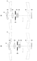
- FIG. 2 is a diagram showing a ray trajectory of light passing through the first optical system. As shown in the figure, the light incident on the first optical system 20 passes through the first wide-angle lens 20a, the second wide-angle lens 20b, the third wide-angle lens 20c, and the fourth wide-angle lens 20d in this order. , Enters the common lens 40.
- FIG. 3 is a diagram showing a ray trajectory of light passing through the second optical system. As shown in the figure, the light incident on the second optical system 30 is transmitted through the first telephoto lens 30a, reflected by the first telephoto mirror 30b, and further reflected by the second telephoto mirror 30c. The light enters the common lens 40.
- the first diaphragm blade support member 54 is formed of an annular plate material as shown in FIG.
- the first diaphragm blade support member 54 is disposed coaxially with the annular first light shielding portion 58.
- the first diaphragm blade support member 54 is provided with a plurality of bearing holes 54A.
- the bearing holes 54A are arranged at a constant interval on the same circumference.
- the bearing hole 54A constitutes a first fulcrum.
- FIG. 6 is an explanatory diagram of the operation of the first diaphragm.
- the first screw rod 76A is arranged in parallel with the optical axis L.
- the lens barrel 12 is provided with a support portion that rotatably supports the first guide shaft 74A.
- the first screw rod 76A is arranged in parallel with the optical axis L, with both ends supported by the support portion.
- the first nut 76B is provided to be movable along the first screw rod 76A by being fitted to the first screw rod 76A. Since the first screw rod 76A is disposed along the optical axis L, the first nut 76B moves along the optical axis L.
- the first drive arm 76C connects the first nut 76B and the first optical system holding member 72. Thereby, the 1st optical system holding member 72 moves with the 1st nut 76B.
- the first optical system drive motor 76D is provided in the lens barrel 12 and rotationally drives the first screw rod 76A.
- the first optical system driving unit 70 configured as described above, when the first optical system driving motor 76D is driven, the first screw rod 76A rotates. When the first screw rod 76A rotates, the first nut 76B moves along the first screw rod 76A. As a result, the first optical system holding member 72 connected to the first nut 76B moves along the optical axis L, and the first optical system 20 and the first diaphragm held by the first optical system holding member 72 are moved. 50 moves along the optical axis L.
- FIG. 15 is a schematic configuration diagram of an image sensor.
- FIG. 16 is a conceptual diagram of a configuration in which a light beam incident through the first optical system and the second optical system is divided into pupils and selectively received by each pixel.
- FIG. 18B shows the light receiving state of each pixel when there is a diaphragm.
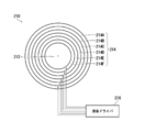
- the second diaphragm 220 has a disk-like outer shape.
- the second diaphragm 220 includes a central light-transmitting region 222 in a circular shape in the central portion, and an annular outer light-transmitting region 224 in the outer peripheral portion.
- An annular light transmitting / shielding variable region 226 is provided between the central light transmitting region 222 and the outer peripheral light transmitting region 224.
- the central light-transmitting region 222 and the outer peripheral light-transmitting region 224 are light-transmitting regions that can always transmit light.
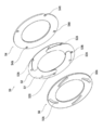
- FIG. 24 is an exploded perspective view of the common diaphragm.
- FIG. 25 is a front view of the diaphragm blades constituting the common diaphragm
- FIG. 26 is a front view showing the arrangement configuration of the diaphragm blades.
- Each aperture blade 302 is provided with a cam groove 302D.
- a cam pin 306B is fitted in each cam groove 302D.
- the inner diameter and the outer diameter of the common light shielding portion 308 are expanded and contracted.
- the inner diameter of the common light-shielding portion 308 is reduced in conjunction with the increase in the outer diameter, and the inner diameter is increased in conjunction with the reduction in the outer diameter.
- the common diaphragm 300 is disposed between the second wide-angle lens 20b and the third wide-angle lens 20c constituting the first optical system 20.
- the common diaphragm 300 is arranged such that the common light shielding unit 308 shields the boundary between the pupil regions of the first optical system 20 and the second optical system 30. More specifically, the common light shielding unit 308 is disposed so as to shield the boundary between the pupil regions of the first optical system 20 and the second optical system 30 in the aperture release state.
- FIG. 31 is an operation explanatory diagram of the first optical system driven by the second optical system driving unit.
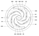
- the opening amount of the common diaphragm 320 configured as described above is adjusted by individually controlling the states of the annular regions 326A to 326G constituting the light transmission / light shielding variable region 326.
- the annular region 326D located at the center of the light transmitting / shielding variable region 326 is set in a light shielding state, and the other annular regions 326A to 326C, 326E to 326G are set.
- a light-transmitting state is assumed.
- FIG. 33 is a block diagram illustrating a system configuration of the imaging apparatus.
- the lens device 10 includes a first optical system 20, a second optical system 30, a common lens 40, a first diaphragm 50, and a second diaphragm 60.
- the image sensor 100 includes a first pixel 110A that selectively receives light that has passed through the first optical system 20, and a second pixel 110B that selectively receives light that has passed through the second optical system 30, and includes a first optical sensor.
- a light beam incident through the system 20 and the second optical system 30 is divided into pupils and selectively received by each pixel.
- the system control unit 408 controls the first diaphragm 50 and the second diaphragm 60 via the lens drive control unit 401, and the first diaphragm 50 and the second diaphragm 60 are measured by photometry. Set the obtained aperture value. Then, the image sensor 100 is exposed at a shutter speed obtained by photometry, and an image for recording is taken.
- 1st drive mechanism 76A ... 1st screw rod, 76B ... 1st nut, 76C ... 1st drive arm, 76D ... 1st DESCRIPTION OF SYMBOLS 1 optical system drive motor, 78D ... 2nd optical system drive motor, 80 ... 2nd optical system drive part, 82 ... 2nd optical system holding member, 84 ... 2nd guide mechanism, 84A ... 2nd guide shaft, 84B ... 1st 2 guide sleeves, 84C ... second guide arm, 86 ... second drive mechanism, 86A ... second screw rod, 86B ... second nut, 86C ... second drive arm, 86D ... second optical system drive motor, 100 ... image Sensor, 110A ...
Landscapes
- Physics & Mathematics (AREA)
- General Physics & Mathematics (AREA)
- Optics & Photonics (AREA)
- Engineering & Computer Science (AREA)
- Multimedia (AREA)
- Signal Processing (AREA)
- General Engineering & Computer Science (AREA)
- Lens Barrels (AREA)
- Diaphragms For Cameras (AREA)
- Optical Elements Other Than Lenses (AREA)
- Cameras In General (AREA)
- Lenses (AREA)
- Structure And Mechanism Of Cameras (AREA)
Abstract
The purpose of the present invention is to provide a lens device that: comprises a first optical system and a second optical system that are concentrically combined; can adjust the light volumes for each optical system individually; and can adjust the focal point for each optical system individually. The lens device (10) comprising a first optical system (20) and a second optical system (30) that are concentrically combined comprises: a first aperture (50) that adjusts the light volume for the first optical system; and a second aperture (60) that adjusts the light volume for the second optical system. As a result, light volumes for the first and second optical systems can be adjusted individually. The first optical system is provided so as to be movable along an optical axis L together with the first aperture and the second optical system is provided so as to be movable along the optical axis L together with the second aperture. As a result, the focal points for the first and second optical systems can be adjusted individually.
Description
本発明は、レンズ装置に係り、特に第1光学系及び第2光学系を同心状に組み合わせて構成されるレンズ装置に関する。
The present invention relates to a lens apparatus, and more particularly to a lens apparatus configured by concentrically combining a first optical system and a second optical system.
第1光学系及び第2光学系を同心状に組み合せて構成されるレンズ装置と、そのレンズ装置の第1光学系及び第2光学系を介して入射する光束をそれぞれ瞳分割して各画素で選択的に受光するイメージセンサと、を使用して、2枚の画像を同時に撮像する撮像装置が知られている(たとえば、特許文献1)。この撮像装置を用いれば、たとえば、第1光学系を広角、第2光学系を望遠の光学系で構成することにより、広角画像及び望遠画像を同時に撮像できる。
A lens device configured by concentrically combining a first optical system and a second optical system, and a light beam incident through the first optical system and the second optical system of the lens device are each pupil-divided to obtain each pixel. An image pickup apparatus that picks up two images simultaneously using an image sensor that selectively receives light is known (for example, Patent Document 1). By using this imaging apparatus, for example, a wide-angle image and a telephoto image can be simultaneously captured by configuring the first optical system with a wide-angle and the second optical system with a telephoto optical system.
しかしながら、従来、この種の撮像装置に用いられるレンズ装置は、絞りが備えられていないため、光量調整ができない、という問題があった。
However, conventionally, a lens device used in this type of imaging apparatus has a problem that the amount of light cannot be adjusted because the diaphragm is not provided.
また、焦点調節についても、各光学系に共通のレンズを光軸方向に前後移動させて行う構成、又は、イメージセンサを光軸方向に前後移動させて行う構成のため、個別に調整できない、という欠点があった。
In addition, the focus adjustment is also performed by moving the lens common to each optical system back and forth in the optical axis direction, or by moving the image sensor back and forth in the optical axis direction, and cannot be adjusted individually. There were drawbacks.
本発明は、このような事情に鑑みてなされたもので、各光学系の光量を個別に調整でき、かつ、各光学系を個別に焦点調整できるレンズ装置を提供することを目的とする。
The present invention has been made in view of such circumstances, and an object thereof is to provide a lens device capable of individually adjusting the light amount of each optical system and individually adjusting the focus of each optical system.
課題を解決するための手段は、次のとおりである。
The means for solving the problem are as follows.
(1)第1光学系と、第1光学系と同心状に配置される環状の第2光学系と、第1光学系を通過する光の光量を調整する第1絞りと、第2光学系を通過する光の光量を調整する第2絞りと、第1光学系及び第1絞りを光軸に沿って一体的に移動させる第1光学系駆動部と、第2光学系及び第2絞りを光軸に沿って一体的に移動させる第2光学系駆動部と、を備えたレンズ装置。
(1) a first optical system, an annular second optical system disposed concentrically with the first optical system, a first diaphragm for adjusting the amount of light passing through the first optical system, and a second optical system A second diaphragm that adjusts the amount of light passing through the first optical system, a first optical system driving unit that integrally moves the first optical system and the first diaphragm along the optical axis, and a second optical system and the second diaphragm. And a second optical system drive unit that moves integrally along the optical axis.
本態様によれば、第1光学系及び第2光学系を同心状に組み合わせて構成されるレンズ装置において、第1光学系の光量を調整する第1絞り、及び、第2光学系の光量を調整する第2絞りが備えられる。これにより、第1光学系及び第2光学系の光量を個別に調整できる。また、本態様によれば、第1光学系を光軸に沿って移動させる第1光学系駆動部、及び、第2光学系を光軸に沿って移動させる第2光学系駆動部が備えられる。これにより、第1光学系及び第2光学系を個別に焦点調整できる。更に、各光学系を移動させる際、絞りを一体的に移動させるので、各光学系の最適な位置で光量を調整できる。
According to this aspect, in the lens device configured by concentrically combining the first optical system and the second optical system, the first diaphragm for adjusting the light amount of the first optical system and the light amount of the second optical system are set. A second aperture for adjustment is provided. Thereby, the light quantity of a 1st optical system and a 2nd optical system can be adjusted separately. In addition, according to this aspect, the first optical system driving unit that moves the first optical system along the optical axis and the second optical system driving unit that moves the second optical system along the optical axis are provided. . Thereby, it is possible to individually adjust the focus of the first optical system and the second optical system. Furthermore, when moving each optical system, the diaphragm is moved integrally, so that the amount of light can be adjusted at the optimum position of each optical system.
(2)上記(1)のレンズ装置において、第1絞りは、内径が拡縮可能な環状の第1遮光部を備え、第2絞りは、外径が拡縮可能な環状の第2遮光部を備える、レンズ装置。
(2) In the lens device of (1), the first diaphragm includes an annular first light-shielding portion whose inner diameter can be expanded and contracted, and the second diaphragm includes an annular second light-shielding portion whose outer diameter can be expanded and contracted. , Lens device.
本態様によれば、第1絞りは、内径が拡縮可能な環状の第1遮光部を備え、その第1遮光部の内径が拡縮することにより、遮光される領域が内側に拡がって第1光学系の光量が調整される。また、第2絞りは、外径が拡縮可能な環状の第2遮光部を備え、その第2遮光部の外径が拡縮することにより、遮光される領域が外側に拡がって第2光学系の光量が調整される。
According to this aspect, the first diaphragm includes the annular first light-shielding portion whose inner diameter can be expanded and contracted, and the inner diameter of the first light-shielding portion expands and contracts, so that the light-shielded region expands inward and the first optical The amount of light in the system is adjusted. The second diaphragm includes an annular second light-shielding portion whose outer diameter can be expanded and contracted, and the outer diameter of the second light-shielding portion expands and contracts, so that the light-shielded region expands outward and the second optical system The amount of light is adjusted.
(3)上記(2)のレンズ装置において、第2絞りは、同一円周上に一定の間隔において配置される複数の第2支点と、第2支点に揺動可能に支持され、かつ、重ねて配置されて第2遮光部を構成する複数枚の第2絞り羽根と、第2絞り羽根を同期して揺動させる第2絞り羽根駆動部と、を備え、第2絞り羽根駆動部によって第2絞り羽根を同期して揺動させることにより、第2遮光部の外径が拡縮して、第2光学系を通過する光の光量を調整する。
(3) In the lens device according to (2), the second diaphragm is supported on a plurality of second fulcrums arranged at regular intervals on the same circumference, and is swingably supported by the second fulcrum, and overlapped. And a plurality of second diaphragm blades that constitute the second light shielding unit and a second diaphragm blade drive unit that swings the second diaphragm blades in synchronization with each other. By oscillating the two diaphragm blades in synchronization, the outer diameter of the second light-shielding portion is expanded and contracted, and the amount of light passing through the second optical system is adjusted.
本態様によれば、環状の第2遮光部が、複数枚の第2絞り羽根を重ねて配置することにより構成される。第2絞りは、この複数枚の第2絞り羽根を同期して揺動させることにより、第2遮光部の外径が拡縮する。
According to this aspect, the annular second light-shielding portion is configured by arranging a plurality of second diaphragm blades in an overlapping manner. The second diaphragm expands or contracts the outer diameter of the second light-shielding portion by swinging the plurality of second diaphragm blades in synchronization.
(4)上記(3)のレンズ装置において、第2絞り羽根駆動部は、第2遮光部と同軸上に配置され、周方向に揺動可能な環状の第2絞り羽根揺動駆動部材と、第2絞り羽根揺動駆動部材及び第2絞り羽根のいずれか一方に設けられる第2カム溝と、他方に設けられる第2カムピンと、を備える。
(4) In the lens device according to (3), the second diaphragm blade drive unit is disposed coaxially with the second light shielding unit, and has an annular second diaphragm blade swing drive member that can swing in the circumferential direction. A second cam groove provided on one of the second diaphragm blade swing drive member and the second diaphragm blade, and a second cam pin provided on the other.
本態様によれば、第2絞り羽根駆動部が、いわゆるカム機構で構成される。これにより、簡素な構成で第2絞りを駆動できる。
According to this aspect, the second diaphragm blade drive unit is configured by a so-called cam mechanism. Thereby, the second diaphragm can be driven with a simple configuration.
(5)上記(4)のレンズ装置において、透明な第2絞り羽根支持部材を更に備え、第2絞り羽根支持部材に第2支点が備えられる。
(5) In the lens device according to (4), a transparent second diaphragm blade support member is further provided, and the second diaphragm blade support member is provided with a second fulcrum.
本態様によれば、透明な第2絞り羽根支持部材に第2支点が備えられる。これにより、光が通過する領域において、光の通過を遮ることなく第2絞りを支持できる。
According to this aspect, the second fulcrum is provided on the transparent second diaphragm blade support member. As a result, the second diaphragm can be supported in a region through which light passes without blocking the passage of light.
(6)上記(2)のレンズ装置において、第2絞りは、液晶素子によって構成される。
(6) In the lens device of (2) above, the second diaphragm is configured by a liquid crystal element.
本態様によれば、第2絞りが液晶素子によって構成される。この場合、たとえば、環状の遮光領域を液晶によって形成し、その遮光領域の外径を拡縮させて、第2光学系を通過する光の光量を調整する。第2光学系は、内側から外側に向かって遮光する領域が拡がり、通過する光量が減少するように調整される。
According to this aspect, the second diaphragm is constituted by a liquid crystal element. In this case, for example, an annular light shielding region is formed of liquid crystal, and the outer diameter of the light shielding region is enlarged and reduced to adjust the amount of light passing through the second optical system. The second optical system is adjusted so that the light shielding area is expanded from the inside toward the outside, and the amount of light passing therethrough is reduced.
(7)上記(2)から(6)のレンズ装置において、第1絞りは、同一円周上に一定の間隔において配置される複数の第1支点と、第1支点に揺動可能に支持され、かつ、重ねて配置されて第1遮光部を構成する複数枚の第1絞り羽根と、第1絞り羽根を同期して揺動させる第1絞り羽根駆動部と、を備え、第1絞り羽根駆動部によって第1絞り羽根を同期して揺動させることにより、第1遮光部の内径が拡縮して、第1光学系を通過する光の光量を調整する。
(7) In the lens devices according to (2) to (6), the first diaphragm is supported by a plurality of first fulcrums arranged at regular intervals on the same circumference and swingable on the first fulcrum. And a plurality of first diaphragm blades arranged in a stacked manner to constitute the first light shielding portion, and a first diaphragm blade drive unit that swings the first diaphragm blades synchronously, and the first diaphragm blades By oscillating the first diaphragm blades synchronously by the driving unit, the inner diameter of the first light shielding unit is expanded and contracted, and the amount of light passing through the first optical system is adjusted.
本態様によれば、環状の第1遮光部が、複数枚の第1絞り羽根を重ねて配置することにより構成される。第1絞りは、この複数枚の第1絞り羽根を同期して揺動させることにより、第1遮光部の内径が拡縮する。
According to this aspect, the annular first light shielding portion is configured by arranging a plurality of first diaphragm blades in a stacked manner. The first diaphragm expands or contracts the inner diameter of the first light-shielding portion by swinging the plurality of first diaphragm blades in synchronization.
(8)上記(7)のレンズ装置において、第1絞り羽根駆動部は、第1遮光部と同軸上に配置され、周方向に揺動可能な環状の第1絞り羽根揺動駆動部材と、第1絞り羽根揺動駆動部材及び第1絞り羽根のいずれか一方に設けられる第1カム溝と、他方に設けられる第1カムピンと、を備える。
(8) In the lens device according to (7), the first diaphragm blade drive unit is disposed coaxially with the first light shielding unit, and is an annular first diaphragm blade rocking drive member that can rock in the circumferential direction. A first cam groove provided in one of the first diaphragm blade swing driving member and the first diaphragm blade, and a first cam pin provided in the other.
本態様によれば、第1絞り羽根駆動部が、いわゆるカム機構で構成される。これにより、簡素な構成で第1絞りを駆動できる。
According to this aspect, the first diaphragm blade drive unit is configured by a so-called cam mechanism. Thereby, the first diaphragm can be driven with a simple configuration.
(9)上記(8)のレンズ装置において、透明な第1絞り羽根支持部材を更に備え、第1絞り羽根支持部材に第1支点が備えられる。
(9) In the lens device of (8), the first diaphragm blade support member is further provided, and the first diaphragm blade support member is provided with the first fulcrum.
本態様によれば、透明な第1絞り羽根支持部材に第1支点が備えられる。これにより、光が通過する領域において、光の通過を遮ることなく第1絞りを支持できる。
According to this aspect, the transparent first diaphragm blade support member is provided with the first fulcrum. As a result, the first diaphragm can be supported in a region through which light passes without blocking the passage of light.
(10)上記(2)から(6)のレンズ装置において、第1絞りは、液晶素子によって構成される。
(10) In the lens device according to (2) to (6) above, the first diaphragm is constituted by a liquid crystal element.
本態様によれば、第1絞りが液晶素子によって構成される。この場合、たとえば、環状の遮光領域を液晶によって形成し、その遮光領域の内径を拡縮させて、第1光学系を通過する光の光量を調整する。第1光学系は、外側から内側に向かって遮光する領域が拡がり、通過する光量が減少するように調整される。
According to this aspect, the first diaphragm is constituted by a liquid crystal element. In this case, for example, an annular light shielding region is formed of liquid crystal, and the inner diameter of the light shielding region is enlarged / reduced to adjust the amount of light passing through the first optical system. The first optical system is adjusted so that the light shielding area is expanded from the outside toward the inside, and the amount of light passing therethrough is reduced.
(11)第1光学系と、第1光学系と同心状に配置される環状の第2光学系と、第1光学系を光軸に沿って移動させる第1光学系駆動部と、第2光学系を光軸に沿って移動させる第2光学系駆動部と、第1光学系及び第2光学系の境界を遮光し、内径及び外径が拡縮可能な環状の共通遮光部を備え、共通遮光部の内径及び外径を拡縮させて、第1光学系及び第2光学系を通過する光の光量を調整する共通絞りと、を備えたレンズ装置。
(11) a first optical system, an annular second optical system disposed concentrically with the first optical system, a first optical system driving unit that moves the first optical system along the optical axis, and a second A second optical system drive unit that moves the optical system along the optical axis, and a common annular light shielding unit that shields light from the boundary between the first optical system and the second optical system and can expand and contract the inner and outer diameters. A lens device comprising: a common diaphragm for adjusting an amount of light passing through the first optical system and the second optical system by expanding and contracting an inner diameter and an outer diameter of the light shielding portion.
本態様によれば、第1光学系を光軸に沿って移動させる第1光学系駆動部、及び、第2光学系を光軸に沿って移動させる第2光学系駆動部が備えられる。これにより、第1光学系及び第2光学系を個別に焦点調整できる。また、本態様によれば、第1光学系及び第2光学系を同心状に組み合わせて構成されるレンズ装置において、第1光学系及び第2光学系の光量を同時に調整する共通絞りが備えられる。これにより、レンズ装置をコンパクト化できる。
According to this aspect, the first optical system driving unit that moves the first optical system along the optical axis and the second optical system driving unit that moves the second optical system along the optical axis are provided. Thereby, it is possible to individually adjust the focus of the first optical system and the second optical system. According to this aspect, in the lens device configured by concentrically combining the first optical system and the second optical system, the common diaphragm for simultaneously adjusting the light amounts of the first optical system and the second optical system is provided. . Thereby, the lens device can be made compact.
なお、第1光学系及び第2光学系の境界とは、第1光学系及び第2光学系の瞳領域の境界を意味する。
Note that the boundary between the first optical system and the second optical system means the boundary between the pupil regions of the first optical system and the second optical system.
(12)上記(11)のレンズ装置において、共通絞りは、同一円周上に一定の間隔において配置される複数の支点と、支点に揺動可能に支持され、かつ、重ねて配置されて共通遮光部を構成する複数枚の絞り羽根と、絞り羽根を同期して揺動させる絞り羽根駆動部と、を備え、絞り羽根駆動部によって絞り羽根を同期して揺動させることにより、共通遮光部の外径の拡大に連動して内径を縮小し、かつ、外径の縮小に連動して内径を拡大して、第1光学系及び第2光学系を通過する光の光量を調整する。
(12) In the lens device according to (11), the common diaphragm is shared by a plurality of fulcrums arranged at regular intervals on the same circumference, and supported by the fulcrum so as to be swingable, and arranged in an overlapping manner. A plurality of diaphragm blades constituting the light shielding portion, and a diaphragm blade driving unit that causes the diaphragm blades to swing in synchronization, and the diaphragm blades are synchronously swung by the diaphragm blade driving unit, thereby providing a common light shielding unit. The inner diameter is reduced in conjunction with the increase in the outer diameter of the lens, and the inner diameter is increased in conjunction with the reduction in the outer diameter, thereby adjusting the amount of light passing through the first optical system and the second optical system.
本態様によれば、共通絞りが、環状の共通遮光部を備え、その共通遮光部の外径及び内径を拡縮させて、第1光学系及び第2光学系の光量を同時に調整する。この際、共通遮光部は外径の拡大に連動して内径が縮小し、かつ、外径の縮小に連動して内径が拡大する。共通遮光部の外径が拡大すると、第2光学系の遮光領域が内側から外側に向かって拡がり、第2光学系を通過する光量が減少するように調整される。また、共通遮光部の内径が縮小すると、第1光学系の遮光領域が外側から内側に向かって拡がり、第1光学系を通過する光量が減少するように調整される。したがって、第1光学系及び第2光学系は同時に絞られ、かつ、同時に開口される。共通遮光部は、複数枚の絞り羽根を重ねて配置することにより構成され、この複数枚の絞り羽根を同期して揺動させることにより、外径及び内径が互いに連動して拡縮する。
According to this aspect, the common diaphragm includes the annular common light shielding portion, and the outer diameter and the inner diameter of the common light shielding portion are enlarged and reduced to simultaneously adjust the light amounts of the first optical system and the second optical system. At this time, the inner diameter of the common light-shielding portion is reduced in conjunction with the increase in the outer diameter, and the inner diameter is increased in association with the reduction in the outer diameter. When the outer diameter of the common light-shielding part is increased, the light-shielding region of the second optical system is expanded from the inside toward the outside, and the amount of light passing through the second optical system is adjusted to decrease. Further, when the inner diameter of the common light shielding portion is reduced, the light shielding region of the first optical system is expanded from the outside to the inside, and the amount of light passing through the first optical system is adjusted to be reduced. Therefore, the first optical system and the second optical system are simultaneously stopped and simultaneously opened. The common light-shielding part is configured by arranging a plurality of diaphragm blades in an overlapping manner, and the outer diameter and the inner diameter are expanded and contracted in conjunction with each other by rocking the plurality of diaphragm blades in synchronization.
(13)上記(12)のレンズ装置において、絞り羽根駆動部は、共通遮光部と同軸上に配置され、周方向に揺動可能な環状の絞り羽根揺動駆動部材と、絞り羽根揺動駆動部材及び絞り羽根のいずれか一方に設けられるカム溝と、他方に設けられるカムピンと、を備える。
(13) In the lens device of (12), the diaphragm blade drive unit is disposed coaxially with the common light-shielding unit, and is configured to have an annular diaphragm blade swing drive member that can swing in the circumferential direction, and a diaphragm blade swing drive. The cam groove provided in any one of a member and an aperture blade, and the cam pin provided in the other are provided.
本態様によれば、絞り羽根駆動部が、いわゆるカム機構で構成される。これにより、簡素な構成で共通絞りを駆動できる。
According to this aspect, the diaphragm blade drive unit is configured by a so-called cam mechanism. Thus, the common diaphragm can be driven with a simple configuration.
(14)上記(13)のレンズ装置において、透明な絞り羽根支持部材を更に備え、絞り羽根支持部材に支点が備えられる。
(14) In the lens device according to (13), the diaphragm blade support member is further provided, and the diaphragm blade support member is provided with a fulcrum.
本態様によれば、透明な絞り羽根支持部材に支点が備えられる。これにより、光が通過する領域において、光の通過を遮ることなく共通絞りを支持できる。
According to this aspect, the transparent diaphragm blade support member is provided with a fulcrum. As a result, the common diaphragm can be supported without blocking the passage of light in the region through which the light passes.
(15)上記(11)のレンズ装置において、共通絞りは、液晶素子によって構成される。
(15) In the lens device of (11) above, the common diaphragm is configured by a liquid crystal element.
本態様によれば、共通絞りが液晶素子によって構成される。この場合、たとえば、環状の遮光領域を液晶によって形成し、その遮光領域の外径及び内径を拡縮させて、第1光学系及び第2光学系を通過する光の光量を調整する。
According to this aspect, the common diaphragm is configured by a liquid crystal element. In this case, for example, an annular light shielding region is formed of liquid crystal, and the outer diameter and inner diameter of the light shielding region are expanded and contracted to adjust the amount of light passing through the first optical system and the second optical system.
(16)上記(11)から(15)のレンズ装置において、第1光学系駆動部は、第1光学系及び共通絞りを光軸に沿って一体的に移動させる。
(16) In the lens device according to (11) to (15) above, the first optical system driving unit moves the first optical system and the common diaphragm integrally along the optical axis.
本態様によれば、共通絞りが第1光学系と一体となって移動する。
According to this aspect, the common diaphragm moves integrally with the first optical system.
(17)上記(11)から(15)のレンズ装置において、第2光学系駆動部は、第2光学系及び共通絞りを光軸に沿って一体的に移動させる。
(17) In the lens device according to (11) to (15) above, the second optical system driving unit moves the second optical system and the common diaphragm integrally along the optical axis.
本態様によれば、共通絞りが第2光学系と一体となって移動する。
According to this aspect, the common diaphragm moves integrally with the second optical system.
(18)上記(11)から(15)のレンズ装置において、共通絞りは、一定位置に固定される。
(18) In the lens devices of (11) to (15) above, the common diaphragm is fixed at a fixed position.
本態様によれば、共通絞りが一定位置に固定されて設置される。
に よ According to this aspect, the common aperture is fixed and installed at a fixed position.
(19)上記(1)から(18)のレンズ装置において、共通絞りを光軸に沿って移動させる共通絞り移動部を更に備えた、レンズ装置。
(19) The lens apparatus according to (1) to (18), further including a common diaphragm moving unit that moves the common diaphragm along the optical axis.
本態様によれば、共通絞りが光軸に沿って移動可能に設けられる。これにより、第1光学系及び第2光学系の位置に応じて、共通絞りを最適な位置に設置できる。
According to this aspect, the common diaphragm is provided to be movable along the optical axis. Accordingly, the common diaphragm can be installed at an optimum position according to the positions of the first optical system and the second optical system.
(20)第1光学系及び第2光学系は、互いに異なる撮像特性を有する。
(20) The first optical system and the second optical system have different imaging characteristics.
本態様によれば、第1光学系及び第2光学系の撮像特性が互いに異なる。これにより、撮像特性の異なる画像を同時に撮像できる。
According to this aspect, the imaging characteristics of the first optical system and the second optical system are different from each other. Thereby, it is possible to simultaneously capture images having different imaging characteristics.
(21)上記(20)のレンズ装置において、第1光学系及び第2光学系は、互いに焦点距離が異なる。
(21) In the lens device of (20), the first optical system and the second optical system have different focal lengths.
本態様によれば、互いに焦点距離の異なる光学系によって第1光学系及び第2光学系が構成される。たとえば、第2光学系より焦点距離の短い光学系で第1光学系が構成される場合、第1光学系を通して画角の広い広角画像、第2光学系を通して画角の狭い望遠画像を撮像できる。
According to this aspect, the first optical system and the second optical system are configured by optical systems having different focal lengths. For example, when the first optical system is configured with an optical system having a shorter focal length than the second optical system, a wide-angle image with a wide field angle can be captured through the first optical system, and a telephoto image with a narrow field angle can be captured through the second optical system. .
(22)上記(20)のレンズ装置において、第1光学系及び第2光学系は、互いに合焦距離が異なる。
(22) In the lens device of (20) above, the first optical system and the second optical system have different in-focus distances.
本態様によれば、互いに合焦距離が異なる光学系によって第1光学系及び第2光学系が構成される。たとえば、第2光学系よりも近距離で合焦する光学系で第1光学系が構成される場合、第1光学系を通して近距離の画像、第2光学系を通して遠距離の画像を撮像できる。
According to this aspect, the first optical system and the second optical system are configured by optical systems having different in-focus distances. For example, when the first optical system is configured by an optical system that focuses at a shorter distance than the second optical system, it is possible to capture a short-distance image through the first optical system and a long-distance image through the second optical system.
(23)上記(20)のレンズ装置において、第1光学系及び第2光学系は、互いに透過波長特性が異なる。
(23) In the lens device of (20) above, the first optical system and the second optical system have different transmission wavelength characteristics.
本態様によれば、互いに透過波長特性の異なる光学系によって第1光学系及び第2光学系が構成される。たとえば、第1光学系は可視光による撮影に適した透過波長特性を有する光学系で構成し、第2光学系は赤外光による撮影に適した透過波長特性を有する光学系で構成することにより、第1光学系を通して可視光画像、第2光学系を通して赤外線画像を撮像できる。
According to this aspect, the first optical system and the second optical system are configured by optical systems having different transmission wavelength characteristics. For example, the first optical system is composed of an optical system having transmission wavelength characteristics suitable for photographing with visible light, and the second optical system is composed of an optical system having transmission wavelength characteristics suitable for photographing with infrared light. A visible light image can be captured through the first optical system, and an infrared image can be captured through the second optical system.
本発明によれば、各光学系の光量を個別に調整でき、かつ、各光学系を個別に焦点調整できる。
According to the present invention, the amount of light of each optical system can be adjusted individually, and the focus of each optical system can be adjusted individually.
以下、添付図面に従って本発明の好ましい実施の形態について詳説する。
Hereinafter, preferred embodiments of the present invention will be described in detail with reference to the accompanying drawings.
[第1の実施の形態]
《撮像ユニット》
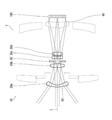
図1は、レンズ装置及びイメージセンサで構成される撮像ユニットの概略構成図である。 [First Embodiment]
<Imaging unit>
FIG. 1 is a schematic configuration diagram of an imaging unit including a lens device and an image sensor.
《撮像ユニット》
図1は、レンズ装置及びイメージセンサで構成される撮像ユニットの概略構成図である。 [First Embodiment]
<Imaging unit>
FIG. 1 is a schematic configuration diagram of an imaging unit including a lens device and an image sensor.
撮像ユニット1は、レンズ装置10及びイメージセンサ100で構成され、レンズ装置10を通った光をイメージセンサ100で受け、電気信号に変換して出力する。
The imaging unit 1 includes a lens device 10 and an image sensor 100. The image sensor 100 receives light that has passed through the lens device 10, converts the light into an electrical signal, and outputs the electrical signal.
レンズ装置10は、第1光学系20及び第2光学系30を同心状に組み合わせて構成される。第1光学系20及び第2光学系30は、互いに撮像特性が異なる光学系で構成される。本実施の形態のレンズ装置10では、互いに焦点距離が異なる光学系によって第1光学系20及び第2光学系30が構成される。特に、本実施の形態のレンズ装置10では、第1光学系20が第2光学系30より焦点距離が短い光学系で構成される。したがって、本実施の形態のレンズ装置10では、第1光学系20を通して画角の広い広角画像が撮像され、第2光学系30を通して画角の狭い望遠画像が撮像される。レンズ装置10の詳細については、後に詳述する。
The lens device 10 is configured by concentrically combining the first optical system 20 and the second optical system 30. The first optical system 20 and the second optical system 30 are optical systems having different imaging characteristics. In the lens apparatus 10 of the present embodiment, the first optical system 20 and the second optical system 30 are configured by optical systems having different focal lengths. In particular, in the lens device 10 of the present embodiment, the first optical system 20 is configured with an optical system having a shorter focal length than the second optical system 30. Therefore, in the lens device 10 of the present embodiment, a wide-angle image with a wide angle of view is captured through the first optical system 20, and a telephoto image with a narrow angle of view is captured through the second optical system 30. Details of the lens device 10 will be described later.
イメージセンサ100は、いわゆる指向性センサで構成され、第1光学系20及び第2光学系30を介して入射する光束をそれぞれ瞳分割して、二次元配列された各画素で選択的に受光し、電気信号に変換する。したがって、第1光学系20を通過した光を受光する画素の電気信号を取得することにより、第1光学系20を介して得られる画像の画像信号を取得でき、第2光学系30を通過した光を受光する画素の電気信号を取得することにより、第2光学系30を介して得られる画像の画像信号を取得できる。イメージセンサ100の詳細については、後に詳述する。
The image sensor 100 is formed of a so-called directional sensor, and the light beams incident through the first optical system 20 and the second optical system 30 are each divided into pupils and selectively received by each pixel arranged two-dimensionally. , Convert to electrical signal. Therefore, an image signal of an image obtained through the first optical system 20 can be acquired by acquiring an electrical signal of a pixel that receives light that has passed through the first optical system 20, and has passed through the second optical system 30. An image signal of an image obtained via the second optical system 30 can be acquired by acquiring an electrical signal of a pixel that receives light. Details of the image sensor 100 will be described later.
《レンズ装置の詳細》
上記のように、レンズ装置10は、互いに焦点距離の異なる第1光学系20及び第2光学系30を同心状に組み合わせて構成される。 <Details of lens device>
As described above, thelens device 10 is configured by concentrically combining the first optical system 20 and the second optical system 30 having different focal lengths.
上記のように、レンズ装置10は、互いに焦点距離の異なる第1光学系20及び第2光学系30を同心状に組み合わせて構成される。 <Details of lens device>
As described above, the
レンズ装置10は、主として、第1光学系20と、第1光学系20と同心状に配置される環状の第2光学系30と、第1光学系20及び第2光学系30で共用される共通レンズ40と、第1光学系20を通過する光の光量を調整する第1絞り50と、第2光学系30を通過する光の光量を調整する第2絞り60と、第1光学系20及び第1絞り50を光軸Lに沿って一体的に移動させる第1光学系駆動部70と、第2光学系30及び第2絞り60を光軸Lに沿って一体的に移動させる第2光学系駆動部80と、を備えて構成される。各構成要素は、図示しないレンズ鏡胴内に配置される。
The lens device 10 is mainly shared by the first optical system 20, the annular second optical system 30 disposed concentrically with the first optical system 20, and the first optical system 20 and the second optical system 30. A first lens 50 that adjusts the amount of light that passes through the first optical system 20, a second aperture 60 that adjusts the amount of light that passes through the second optical system 30, and the first optical system 20. And a first optical system driving unit 70 that integrally moves the first diaphragm 50 along the optical axis L, and a second optical system 30 that integrally moves the second optical system 30 and the second diaphragm 60 along the optical axis L. And an optical system driving unit 80. Each component is disposed in a lens barrel (not shown).
〈第1光学系〉
第1光学系20は、複数枚のレンズを組み合わせて構成される。第1光学系20を構成する広角用のレンズ群は、第1広角用レンズ20a、第2広角用レンズ20b、第3広角用レンズ20c、及び、第4広角用レンズ20dで構成される。第1広角用レンズ20a、第2広角用レンズ20b、第3広角用レンズ20c、及び、第4広角用レンズ20dは、被写体側から第1広角用レンズ20a、第2広角用レンズ20b、第3広角用レンズ20c、第4広角用レンズ20dの順で配置され、それぞれ光軸Lに沿って配置される。 <First optical system>
The firstoptical system 20 is configured by combining a plurality of lenses. The wide-angle lens group constituting the first optical system 20 includes a first wide-angle lens 20a, a second wide-angle lens 20b, a third wide-angle lens 20c, and a fourth wide-angle lens 20d. The first wide-angle lens 20a, the second wide-angle lens 20b, the third wide-angle lens 20c, and the fourth wide-angle lens 20d are the first wide-angle lens 20a, the second wide-angle lens 20b, the third wide-angle lens 20d from the subject side. The wide-angle lens 20c and the fourth wide-angle lens 20d are arranged in this order, and are arranged along the optical axis L, respectively.
第1光学系20は、複数枚のレンズを組み合わせて構成される。第1光学系20を構成する広角用のレンズ群は、第1広角用レンズ20a、第2広角用レンズ20b、第3広角用レンズ20c、及び、第4広角用レンズ20dで構成される。第1広角用レンズ20a、第2広角用レンズ20b、第3広角用レンズ20c、及び、第4広角用レンズ20dは、被写体側から第1広角用レンズ20a、第2広角用レンズ20b、第3広角用レンズ20c、第4広角用レンズ20dの順で配置され、それぞれ光軸Lに沿って配置される。 <First optical system>
The first
図2は、第1光学系を通る光の光線軌跡を示す図である。同図に示すように、第1光学系20に入射した光は、第1広角用レンズ20a、第2広角用レンズ20b、第3広角用レンズ20c、第4広角用レンズ20dの順に通過して、共通レンズ40に入射する。
FIG. 2 is a diagram showing a ray trajectory of light passing through the first optical system. As shown in the figure, the light incident on the first optical system 20 passes through the first wide-angle lens 20a, the second wide-angle lens 20b, the third wide-angle lens 20c, and the fourth wide-angle lens 20d in this order. , Enters the common lens 40.
第1光学系20は、光軸Lに沿って前後移動可能に設けられる。第1光学系20を構成する第1広角用レンズ20a、第2広角用レンズ20b、第3広角用レンズ20c、及び、第4広角用レンズ20dは、その位置関係を一定に保ちながら、光軸Lに沿って移動する。
The first optical system 20 is provided to be movable back and forth along the optical axis L. The first wide-angle lens 20a, the second wide-angle lens 20b, the third wide-angle lens 20c, and the fourth wide-angle lens 20d constituting the first optical system 20 are optical axes while maintaining the positional relationship constant. Move along L.
〈第2光学系〉
第2光学系30は、第1光学系20と同心状に配置される。したがって、その光軸は、第1光学系20と共通である。 <Second optical system>
The secondoptical system 30 is disposed concentrically with the first optical system 20. Therefore, the optical axis is common to the first optical system 20.
第2光学系30は、第1光学系20と同心状に配置される。したがって、その光軸は、第1光学系20と共通である。 <Second optical system>
The second
第2光学系30は、いわゆる反射望遠型の光学系で構成され、円環状のレンズ及び円環状のミラーを組み合わせて構成される。第2光学系30を構成する望遠用のレンズ群は、第1望遠用レンズ30a、第1望遠用ミラー30b、及び、第2望遠用ミラー30cで構成される。第1望遠用レンズ30a、第1望遠用ミラー30b、及び、第2望遠用ミラー30cは、被写体側から共通レンズ40への光路に沿って第1望遠用レンズ30a、第1望遠用ミラー30b、第2望遠用ミラー30cの順で配置され、それぞれ光軸Lに沿って配置される。
The second optical system 30 is configured by a so-called reflective telephoto optical system, and is configured by combining an annular lens and an annular mirror. The telephoto lens group constituting the second optical system 30 includes a first telephoto lens 30a, a first telephoto mirror 30b, and a second telephoto mirror 30c. The first telephoto lens 30a, the first telephoto mirror 30b, and the second telephoto mirror 30c are arranged along the optical path from the subject side to the common lens 40, the first telephoto lens 30a, the first telephoto mirror 30b, The second telephoto mirrors 30c are arranged in this order, and are arranged along the optical axis L, respectively.
図3は、第2光学系を通る光の光線軌跡を示す図である。同図に示すように、第2光学系30に入射した光は、第1望遠用レンズ30aを透過し、第1望遠用ミラー30bで反射し、更に第2望遠用ミラー30cで反射して、共通レンズ40に入射する。
FIG. 3 is a diagram showing a ray trajectory of light passing through the second optical system. As shown in the figure, the light incident on the second optical system 30 is transmitted through the first telephoto lens 30a, reflected by the first telephoto mirror 30b, and further reflected by the second telephoto mirror 30c. The light enters the common lens 40.
第2光学系30は、光軸Lに沿って前後移動可能に設けられる。第2光学系30を構成する第1望遠用レンズ30a、第1望遠用ミラー30b、及び、第2望遠用ミラー30cは、その位置関係を一定に保ちながら、光軸Lに沿って移動する。
The second optical system 30 is provided to be movable back and forth along the optical axis L. The first telephoto lens 30a, the first telephoto mirror 30b, and the second telephoto mirror 30c constituting the second optical system 30 move along the optical axis L while maintaining the positional relationship constant.
〈共通レンズ〉
共通レンズ40は、第1光学系20及び第2光学系30で共用されるレンズであり、光軸L上の一定位置に固定して配置される。共通レンズ40は、イメージセンサ100への光の入射角度を調整する。第1光学系20及び第2光学系30を通過した光は、それぞれ共通レンズ40を介してイメージセンサ100に入射する。 <Common lens>
Thecommon lens 40 is a lens shared by the first optical system 20 and the second optical system 30 and is fixedly disposed at a fixed position on the optical axis L. The common lens 40 adjusts the incident angle of light to the image sensor 100. The light that has passed through the first optical system 20 and the second optical system 30 enters the image sensor 100 via the common lens 40.
共通レンズ40は、第1光学系20及び第2光学系30で共用されるレンズであり、光軸L上の一定位置に固定して配置される。共通レンズ40は、イメージセンサ100への光の入射角度を調整する。第1光学系20及び第2光学系30を通過した光は、それぞれ共通レンズ40を介してイメージセンサ100に入射する。 <Common lens>
The
〈第1絞り〉
第1絞り50は、第1光学系20を通過する光の光量を調整する。第1絞り50は、光軸L上に配置され、第1光学系20を構成する第2広角用レンズ20bと第3広角用レンズ20cとの間に配置される。 <First aperture>
Thefirst diaphragm 50 adjusts the amount of light passing through the first optical system 20. The first diaphragm 50 is disposed on the optical axis L, and is disposed between the second wide-angle lens 20b and the third wide-angle lens 20c constituting the first optical system 20.
第1絞り50は、第1光学系20を通過する光の光量を調整する。第1絞り50は、光軸L上に配置され、第1光学系20を構成する第2広角用レンズ20bと第3広角用レンズ20cとの間に配置される。 <First aperture>
The
図4は、第1絞りの分解斜視図である。また、図5は、第1絞り羽根の配置構成を示す正面図である。
FIG. 4 is an exploded perspective view of the first diaphragm. FIG. 5 is a front view showing the arrangement configuration of the first diaphragm blades.
第1絞り50は、主として、複数枚の第1絞り羽根52と、複数枚の第1絞り羽根52を揺動可能に支持する第1絞り羽根支持部材54と、複数枚の第1絞り羽根52を同期して揺動させる第1絞り羽根揺動駆動部材56と、第1絞り羽根揺動駆動部材56を動作させる第1アクチュエータ(不図示)と、を備えて構成される。
The first diaphragm 50 mainly includes a plurality of first diaphragm blades 52, a first diaphragm blade support member 54 that supports the plurality of first diaphragm blades 52 in a swingable manner, and a plurality of first diaphragm blades 52. The first diaphragm blade swing drive member 56 that swings in synchronization with each other and the first actuator (not shown) that operates the first diaphragm blade swing drive member 56 are configured.
複数枚の第1絞り羽根52は、すべて同一形状を有する。各第1絞り羽根52は、同一円周上に一定の間隔をもって配置され、かつ、隣り合う第1絞り羽根52が互いに重なるように配置される。このように配置された第1絞り羽根52は、図5に示すように、全体として円環状の第1遮光部58を形成する。なお、図5は、第1絞り50を解放した状態、すなわち、第1絞り50を最も開いた状態を示している。この場合、円環状の第1遮光部58の内径は最大となる。
The plurality of first aperture blades 52 all have the same shape. The first aperture blades 52 are arranged at a constant interval on the same circumference, and are arranged so that adjacent first aperture blades 52 overlap each other. As shown in FIG. 5, the first diaphragm blades 52 arranged in this way form a first annular light shielding portion 58 as a whole. FIG. 5 shows a state where the first diaphragm 50 is released, that is, a state where the first diaphragm 50 is most opened. In this case, the inner diameter of the annular first light shielding portion 58 is maximized.
第1絞り羽根支持部材54は、図4に示すように、円環状の板材で構成される。第1絞り羽根支持部材54は、円環状の第1遮光部58と同軸上に配置される。第1絞り羽根支持部材54には、複数の軸受穴54Aが備えられる。軸受穴54Aは、同一円周上に一定の間隔で配置される。軸受穴54Aは、第1支点を構成する。
The first diaphragm blade support member 54 is formed of an annular plate material as shown in FIG. The first diaphragm blade support member 54 is disposed coaxially with the annular first light shielding portion 58. The first diaphragm blade support member 54 is provided with a plurality of bearing holes 54A. The bearing holes 54A are arranged at a constant interval on the same circumference. The bearing hole 54A constitutes a first fulcrum.
各第1絞り羽根52には、軸受穴54Aに嵌合可能な第1揺動軸52Aが備えられる。各第1絞り羽根52は、軸受穴54Aに第1揺動軸52Aが嵌入されることにより、第1絞り羽根支持部材54に対して、揺動自在に支持される。
Each first diaphragm blade 52 is provided with a first swing shaft 52A that can be fitted into the bearing hole 54A. Each of the first diaphragm blades 52 is swingably supported with respect to the first diaphragm blade support member 54 by fitting the first swing shaft 52A into the bearing hole 54A.
第1絞り羽根揺動駆動部材56は、図4に示すように、円環状の板材で構成される。第1絞り羽根揺動駆動部材56は、第1遮光部58と同軸上に配置され、図示しない支持部材に支持されて、周方向に揺動可能に設けられる。第1絞り羽根52は、この第1絞り羽根揺動駆動部材56と第1絞り羽根支持部材54との間に挟まれた状態で配置される。
As shown in FIG. 4, the first diaphragm blade swing drive member 56 is formed of an annular plate material. The first diaphragm blade swing drive member 56 is disposed coaxially with the first light shielding portion 58, is supported by a support member (not shown), and is swingable in the circumferential direction. The first diaphragm blade 52 is disposed in a state of being sandwiched between the first diaphragm blade swing driving member 56 and the first diaphragm blade support member 54.
第1絞り羽根揺動駆動部材56には、複数の第1カム溝56Aが備えられる。複数の第1カム溝56Aは、すべて同じ形状を有し、同一円周上に一定の間隔で配置される。
The first diaphragm blade swing drive member 56 is provided with a plurality of first cam grooves 56A. The plurality of first cam grooves 56A all have the same shape, and are arranged at a constant interval on the same circumference.
各第1絞り羽根52には、第1カムピン52Bが備えられる。各第1カムピン52Bは、第1カム溝56Aに嵌入される。第1カム溝56Aに第1カムピン52Bが嵌入されることにより、第1絞り羽根揺動駆動部材56を揺動させると、その第1絞り羽根揺動駆動部材56の動きに連動して第1絞り羽根52が揺動する。
Each first aperture blade 52 is provided with a first cam pin 52B. Each first cam pin 52B is fitted into the first cam groove 56A. When the first cam pin 52B is inserted into the first cam groove 56A to swing the first diaphragm blade swing drive member 56, the first diaphragm blade swing drive member 56 is interlocked with the movement of the first diaphragm blade swing drive member 56. The diaphragm blade 52 swings.
第1カムピン52B、第1カム溝56A、及び、第1絞り羽根揺動駆動部材56は、第1絞り羽根52を同期して揺動させるための第1絞り羽根駆動部を構成する。
The first cam pin 52B, the first cam groove 56A, and the first diaphragm blade swing drive member 56 constitute a first diaphragm blade drive unit for swinging the first diaphragm blade 52 in synchronization.
図示しない第1アクチュエータは、たとえば、モータで構成され、第1絞り羽根揺動駆動部材56を周方向に揺動させる。
The first actuator (not shown) is constituted by a motor, for example, and swings the first diaphragm blade swing driving member 56 in the circumferential direction.
第1絞り50は、以上のように構成される。
The first diaphragm 50 is configured as described above.
図6は、第1絞りの動作説明図である。
FIG. 6 is an explanatory diagram of the operation of the first diaphragm.
第1絞り羽根揺動駆動部材56を揺動させると、第1カム溝56A及び第1カムピン52Bの作用によって、全ての第1絞り羽根52が、第1支点である軸受穴54Aを中心に同期して揺動する。この結果、第1絞り羽根52によって構成される第1遮光部58の内径が拡縮する。
When the first diaphragm blade swing drive member 56 is swung, all the first diaphragm blades 52 are synchronized around the bearing hole 54A as the first fulcrum by the action of the first cam groove 56A and the first cam pin 52B. And swings. As a result, the inner diameter of the first light shielding portion 58 configured by the first diaphragm blades 52 expands and contracts.
上記のように、第1絞り50は、第2広角用レンズ20bと第3広角用レンズ20cとの間に配置される。第1光学系20に入射した光は、第1絞り50の内側を通って、イメージセンサ100に入射する(図2参照)。より具体的には、第1絞り羽根52によって構成される第1遮光部58の内側を通って、イメージセンサ100に入射する。第1絞り50は、第1絞り羽根52を揺動させると、第1遮光部58の内径が拡縮するので、第1遮光部58の内径を拡縮させることにより、第1光学系20を通る光の光量を調整できる。
As described above, the first diaphragm 50 is disposed between the second wide-angle lens 20b and the third wide-angle lens 20c. The light that has entered the first optical system 20 passes through the inside of the first diaphragm 50 and enters the image sensor 100 (see FIG. 2). More specifically, the light enters the image sensor 100 through the inside of the first light shielding portion 58 formed by the first diaphragm blades 52. When the first diaphragm 50 swings the first diaphragm blade 52, the inner diameter of the first light-shielding part 58 expands and contracts, so that the light passing through the first optical system 20 is expanded and contracted. The amount of light can be adjusted.
なお、第1絞り50の外側は、第2光学系30を通過する光の光路となるので、第1絞り50は、第2光学系30の光路を考慮して設置される。好ましくは、絞り解放状態において、第1遮光部58が、第1光学系20及び第2光学系30の瞳領域の境界を遮光するように設置する。これにより、第1光学系20を通してイメージセンサ100に入射する光と第2光学系30を通してイメージセンサ100に入射する光の分離性を向上でき、混信を効果的に抑制できる。
In addition, since the outside of the first diaphragm 50 is an optical path of light passing through the second optical system 30, the first diaphragm 50 is installed in consideration of the optical path of the second optical system 30. Preferably, the first light shielding unit 58 is installed so as to shield the boundary between the pupil regions of the first optical system 20 and the second optical system 30 in the aperture release state. Thereby, the separability of the light which injects into the image sensor 100 through the 1st optical system 20 and the light which injects into the image sensor 100 through the 2nd optical system 30 can be improved, and interference can be suppressed effectively.
〈第2絞り〉
第2絞り60は、第2光学系30を通過する光の光量を調整する。第2絞り60は、光軸L上に配置され、第2光学系30を構成する第2望遠用ミラー30cの直後に配置される。 <Second aperture>
Thesecond diaphragm 60 adjusts the amount of light passing through the second optical system 30. The second diaphragm 60 is disposed on the optical axis L, and is disposed immediately after the second telephoto mirror 30 c constituting the second optical system 30.
第2絞り60は、第2光学系30を通過する光の光量を調整する。第2絞り60は、光軸L上に配置され、第2光学系30を構成する第2望遠用ミラー30cの直後に配置される。 <Second aperture>
The
図7は、第2絞りの分解斜視図である。また、図8は、第2絞りを構成する第2絞り羽根の正面図であり、図9は、第2絞り羽根の配置構成を示す正面図である。
FIG. 7 is an exploded perspective view of the second diaphragm. FIG. 8 is a front view of the second diaphragm blades constituting the second diaphragm, and FIG. 9 is a front view showing the arrangement configuration of the second diaphragm blades.
図7に示すように、第2絞り60は、主として、複数枚の第2絞り羽根62と、複数枚の第2絞り羽根62を揺動可能に支持する第2絞り羽根支持部材64と、複数枚の第2絞り羽根62を同期して揺動させる第2絞り羽根揺動駆動部材66と、第2絞り羽根揺動駆動部材66を動作させる第2アクチュエータ(不図示)と、を備えて構成される。
As shown in FIG. 7, the second diaphragm 60 mainly includes a plurality of second diaphragm blades 62, a second diaphragm blade support member 64 that supports the plurality of second diaphragm blades 62 in a swingable manner, and a plurality of second diaphragm blades 62. A second diaphragm blade rocking drive member 66 that rocks the second diaphragm blades 62 synchronously; and a second actuator (not shown) that operates the second diaphragm blade rocking drive member 66. Is done.
第2絞り羽根62は、すべて同じ形状であり、図8に示すように、円弧状の外形を有する。各第2絞り羽根62は、図9に示すように、同一円周上に一定の間隔をもって配置され、かつ、隣り合う第2絞り羽根62が互いに重なるように配置される。このように配置された第2絞り羽根62は、全体として円環状の第2遮光部68を形成する。なお、図9は、第2絞り60を解放した状態、すなわち、第2絞り60を最も開いた状態を示している。この場合、第2遮光部68の外径は最小となる。
The second diaphragm blades 62 all have the same shape, and have an arcuate outer shape as shown in FIG. As shown in FIG. 9, the second diaphragm blades 62 are arranged at a constant interval on the same circumference, and are arranged so that adjacent second diaphragm blades 62 overlap each other. The second diaphragm blades 62 arranged in this way form a second annular light shielding portion 68 as a whole. FIG. 9 shows a state where the second diaphragm 60 is released, that is, a state where the second diaphragm 60 is most opened. In this case, the outer diameter of the second light shielding portion 68 is minimized.
第2絞り羽根支持部材64は、第2遮光部68と同軸上に配置される。第2絞り羽根支持部材64は、図7に示すように、内枠64Aと、外枠64Bと、3本の支持アーム64Cと、軸受64Dとを備えて構成される。内枠64A及び外枠64Bは、共に円環状の枠体で構成され、同心状に配置される。3本の支持アーム64Cは、放射状に配置され、内枠64A及び外枠64Bを互いに連結する。軸受64Dは、内枠64Aに備えられ、周方向に一定の間隔で配置される。軸受64Dは、第2支点を構成する。
The second diaphragm blade support member 64 is arranged coaxially with the second light shielding portion 68. As shown in FIG. 7, the second diaphragm blade support member 64 includes an inner frame 64A, an outer frame 64B, three support arms 64C, and a bearing 64D. The inner frame 64A and the outer frame 64B are both constituted by an annular frame and are arranged concentrically. The three support arms 64C are arranged radially and connect the inner frame 64A and the outer frame 64B to each other. The bearings 64D are provided in the inner frame 64A and are arranged at regular intervals in the circumferential direction. The bearing 64D constitutes a second fulcrum.
各第2絞り羽根62の基端部には、軸受64Dに嵌入可能な第2揺動軸62Aが備えられる。各第2絞り羽根62は、第2揺動軸62Aが軸受64Dに嵌入されることにより、第2絞り羽根支持部材64に揺動自在に支持される。
The base end portion of each second diaphragm blade 62 is provided with a second swing shaft 62A that can be fitted into the bearing 64D. Each of the second diaphragm blades 62 is swingably supported by the second diaphragm blade support member 64 by fitting the second swing shaft 62A into the bearing 64D.
第2絞り羽根揺動駆動部材66は、第2遮光部68と同軸上に配置される。第2絞り羽根揺動駆動部材66は、図7に示すように、円環状の板材で構成され、内周部に円環状の嵌合部66Aが備えられる。第2絞り羽根揺動駆動部材66は、嵌合部66Aが、第2絞り羽根支持部材64の内周部に嵌合されることにより、第2絞り羽根支持部材64及び第2遮光部68と同軸上に配置され、かつ、周方向に揺動可能に支持される。
The second diaphragm blade swing drive member 66 is disposed coaxially with the second light shielding portion 68. As shown in FIG. 7, the second diaphragm blade swing drive member 66 is formed of an annular plate material, and an annular fitting portion 66A is provided on the inner peripheral portion. The second diaphragm blade swing drive member 66 is configured such that the fitting portion 66 </ b> A is fitted to the inner peripheral portion of the second diaphragm blade support member 64, whereby the second diaphragm blade support member 64 and the second light shielding portion 68. It is arrange | positioned coaxially and is supported so that rocking | fluctuation is possible in the circumferential direction.
第2絞り羽根揺動駆動部材66には、複数の第2カムピン66Bが備えられる。第2カムピン66Bは、同一円周上に一定の間隔で配置される。
The second diaphragm blade swing drive member 66 is provided with a plurality of second cam pins 66B. The second cam pins 66B are arranged at a constant interval on the same circumference.
各第2絞り羽根62には、第2カム溝62Bが備えられる。各第2カム溝62Bには、第2カムピン66Bが嵌入される。各第2カム溝62Bに第2カムピン66Bが嵌入されることにより、第2絞り羽根揺動駆動部材66を揺動させると、その第2絞り羽根揺動駆動部材66の動きに連動して第2絞り羽根62が揺動する。
Each second diaphragm blade 62 is provided with a second cam groove 62B. A second cam pin 66B is fitted in each second cam groove 62B. When the second diaphragm blade swing driving member 66 is swung by inserting the second cam pin 66B into each second cam groove 62B, the second diaphragm blade swing driving member 66 is interlocked with the movement of the second diaphragm blade swing driving member 66. The two diaphragm blades 62 swing.
第2カム溝62B、第2カムピン66B、及び、第2絞り羽根揺動駆動部材66は、第2絞り羽根62を同期して揺動させるための第2絞り羽根駆動部を構成する。
The second cam groove 62B, the second cam pin 66B, and the second diaphragm blade swing drive member 66 constitute a second diaphragm blade drive unit for swinging the second diaphragm blade 62 in synchronization.
図示しない第2アクチュエータは、たとえば、モータで構成され、第2絞り羽根揺動駆動部材66を周方向に揺動させる。
The second actuator (not shown) is constituted by a motor, for example, and swings the second diaphragm blade swing drive member 66 in the circumferential direction.
図10は、第2絞りの動作説明図である。
FIG. 10 is an explanatory diagram of the operation of the second diaphragm.
第2絞り羽根揺動駆動部材66を揺動させると、第2カムピン66B及び第2カム溝62Bの作用によって、全ての第2絞り羽根62が第2支点を構成する軸受64Dを中心に同期して揺動する。この結果、第2絞り羽根62によって構成される第2遮光部68の外径が拡縮する。
When the second diaphragm blade drive member 66 is swung, the second cam pins 66B and the second cam grooves 62B cause all the second diaphragm blades 62 to synchronize around the bearing 64D that constitutes the second fulcrum. Rocks. As a result, the outer diameter of the second light shielding portion 68 configured by the second diaphragm blades 62 is expanded or reduced.
上記のように、第2絞り60は、第2望遠用ミラー30cの直後に配置される。第2光学系30に入射した光は、第2絞り60の外側を通って、イメージセンサ100に入射する(図3参照)。より具体的には、第2絞り羽根62によって構成される第2遮光部68の外側を通って、イメージセンサ100に入射する。第2絞り60は、第2絞り羽根62を揺動させると、第2遮光部68の外径が拡縮するので、第2遮光部68の外径を拡縮させることにより、第2光学系30を通る光の光量を調整できる。
As described above, the second diaphragm 60 is disposed immediately after the second telephoto mirror 30c. The light incident on the second optical system 30 enters the image sensor 100 through the outside of the second diaphragm 60 (see FIG. 3). More specifically, the light is incident on the image sensor 100 through the outside of the second light shielding portion 68 constituted by the second diaphragm blades 62. When the second diaphragm 60 swings the second diaphragm blade 62, the outer diameter of the second light-shielding portion 68 expands and contracts. By expanding and contracting the outer diameter of the second light-shielding portion 68, the second optical system 30 is moved. The amount of light passing through can be adjusted.
なお、第2絞り60の内側は、第1光学系20を通過する光の光路となるので、第2絞り60は、第2光学系30の光路を考慮して設置される。好ましくは、絞り解放状態において、第2遮光部68が、第1光学系20及び第2光学系30の瞳領域の境界を遮光するように設置する。これにより、第1光学系20を通してイメージセンサ100に入射する光と第2光学系30を通してイメージセンサ100に入射する光の分離性を向上でき、混信を効果的に抑制できる。
In addition, since the inside of the second diaphragm 60 serves as an optical path of light passing through the first optical system 20, the second diaphragm 60 is installed in consideration of the optical path of the second optical system 30. Preferably, the second light shielding unit 68 is installed so as to shield the boundary between the pupil regions of the first optical system 20 and the second optical system 30 in the aperture release state. Thereby, the separability of the light which injects into the image sensor 100 through the 1st optical system 20 and the light which injects into the image sensor 100 through the 2nd optical system 30 can be improved, and interference can be suppressed effectively.
〈第1光学系駆動部〉
第1光学系駆動部70は、第1光学系20及び第1絞り50を光軸Lに沿って一体的に移動させる。 <First optical system drive unit>
The first opticalsystem driving unit 70 integrally moves the first optical system 20 and the first diaphragm 50 along the optical axis L.
第1光学系駆動部70は、第1光学系20及び第1絞り50を光軸Lに沿って一体的に移動させる。 <First optical system drive unit>
The first optical
図11は、第1光学系駆動部の概略構成を示す断面図である。
FIG. 11 is a cross-sectional view showing a schematic configuration of the first optical system driving unit.
第1光学系駆動部70は、第1光学系20を構成するレンズ群及び第1絞り50を保持する第1光学系保持部材72と、第1光学系保持部材72を光軸Lに沿ってガイドする第1ガイド機構74と、第1光学系保持部材72を光軸Lに沿って移動させる第1駆動機構76と、を備えて構成される。
The first optical system driving unit 70 includes a first optical system holding member 72 that holds the lens group and the first diaphragm 50 constituting the first optical system 20, and the first optical system holding member 72 along the optical axis L. A first guide mechanism 74 for guiding and a first drive mechanism 76 for moving the first optical system holding member 72 along the optical axis L are configured.
第1光学系保持部材72は、全体として筒形状を有し、その内側にレンズ保持部を備える。第1光学系20を構成する第1広角用レンズ20a、第2広角用レンズ20b、第3広角用レンズ20c、及び、第4広角用レンズ20dは、このレンズ保持部に保持される。
The first optical system holding member 72 has a cylindrical shape as a whole and includes a lens holding portion inside thereof. The first wide-angle lens 20a, the second wide-angle lens 20b, the third wide-angle lens 20c, and the fourth wide-angle lens 20d constituting the first optical system 20 are held by this lens holding portion.
また、第1光学系保持部材72は、第2広角用レンズ20bのレンズ保持部と第3広角用レンズ20cのレンズ保持部との間に絞り保持部を備える。第1絞り50は、この絞り保持部に保持されて、第1光学系20と一体化される。
The first optical system holding member 72 includes a diaphragm holding unit between the lens holding unit of the second wide-angle lens 20b and the lens holding unit of the third wide-angle lens 20c. The first diaphragm 50 is held by the diaphragm holder and integrated with the first optical system 20.
第1ガイド機構74は、第1ガイド軸74Aと、第1ガイド軸74Aに沿って摺動する第1ガイドスリーブ74Bと、第1ガイドスリーブ74B及び第1光学系保持部材72を連結する第1ガイドアーム74Cと、を備えて構成される。
The first guide mechanism 74 includes a first guide shaft 74A, a first guide sleeve 74B that slides along the first guide shaft 74A, a first guide sleeve 74B, and a first optical system holding member 72. And a guide arm 74C.
第1ガイド軸74Aは、棒形状を有し、光軸Lと平行に配置される。レンズ鏡胴12には、この第1ガイド軸74Aを支持する支持部が備えられる。第1ガイド軸74Aは、両端を支持部に支持されて、光軸Lと平行に配置される。
The first guide shaft 74A has a rod shape and is arranged in parallel with the optical axis L. The lens barrel 12 is provided with a support portion that supports the first guide shaft 74A. The first guide shaft 74A is arranged in parallel to the optical axis L, with both ends supported by the support portion.
第1ガイドスリーブ74Bは、第1ガイド軸74Aに嵌められることにより、第1ガイド軸74Aに沿って摺動可能に設けられる。第1ガイド軸74Aは、光軸Lに沿って配置されるので、第1ガイドスリーブ74Bは、光軸Lに沿って摺動する。
The first guide sleeve 74B is slidably provided along the first guide shaft 74A by being fitted to the first guide shaft 74A. Since the first guide shaft 74A is disposed along the optical axis L, the first guide sleeve 74B slides along the optical axis L.
第1ガイドアーム74Cは、第1ガイドスリーブ74B及び第1光学系保持部材72を連結する。これにより、第1光学系保持部材72が、光軸Lに沿って移動可能に支持される。
The first guide arm 74C connects the first guide sleeve 74B and the first optical system holding member 72. Thereby, the first optical system holding member 72 is supported so as to be movable along the optical axis L.
第1駆動機構76は、いわゆる送りネジ機構で構成され、第1ネジ棒76Aと、第1ナット76Bと、第1ナット76B及び第1光学系保持部材72を連結する第1駆動アーム76Cと、第1光学系駆動モータ76Dと、を備えて構成される。
The first drive mechanism 76 includes a so-called feed screw mechanism, and includes a first screw rod 76A, a first nut 76B, a first drive arm 76C that connects the first nut 76B and the first optical system holding member 72, and And a first optical system drive motor 76D.
第1ネジ棒76Aは、光軸Lと平行に配置される。レンズ鏡胴12には、この第1ガイド軸74Aを回動自在に支持する支持部が備えられる。第1ネジ棒76Aは、両端を支持部に支持されて、光軸Lと平行に配置される。
The first screw rod 76A is arranged in parallel with the optical axis L. The lens barrel 12 is provided with a support portion that rotatably supports the first guide shaft 74A. The first screw rod 76A is arranged in parallel with the optical axis L, with both ends supported by the support portion.
第1ナット76Bは、第1ネジ棒76Aに嵌められることにより、第1ネジ棒76Aに沿って移動可能に設けられる。第1ネジ棒76Aは、光軸Lに沿って配置されるので、第1ナット76Bは、光軸Lに沿って移動する。
The first nut 76B is provided to be movable along the first screw rod 76A by being fitted to the first screw rod 76A. Since the first screw rod 76A is disposed along the optical axis L, the first nut 76B moves along the optical axis L.
第1駆動アーム76Cは、第1ナット76B及び第1光学系保持部材72を連結する。これにより、第1光学系保持部材72が、第1ナット76Bと共に移動する。
The first drive arm 76C connects the first nut 76B and the first optical system holding member 72. Thereby, the 1st optical system holding member 72 moves with the 1st nut 76B.
第1光学系駆動モータ76Dは、レンズ鏡胴12に備えられ、第1ネジ棒76Aを回転駆動する。
The first optical system drive motor 76D is provided in the lens barrel 12 and rotationally drives the first screw rod 76A.
以上のように構成される第1光学系駆動部70は、第1光学系駆動モータ76Dを駆動すると、第1ネジ棒76Aが回転する。第1ネジ棒76Aが回転すると、第1ナット76Bが第1ネジ棒76Aに沿って移動する。この結果、第1ナット76Bに連結された第1光学系保持部材72が、光軸Lに沿って移動し、その第1光学系保持部材72に保持された第1光学系20及び第1絞り50が光軸Lに沿って移動する。
In the first optical system driving unit 70 configured as described above, when the first optical system driving motor 76D is driven, the first screw rod 76A rotates. When the first screw rod 76A rotates, the first nut 76B moves along the first screw rod 76A. As a result, the first optical system holding member 72 connected to the first nut 76B moves along the optical axis L, and the first optical system 20 and the first diaphragm held by the first optical system holding member 72 are moved. 50 moves along the optical axis L.
図12は、第1光学系駆動部によって駆動される第1光学系の動作説明図である。
FIG. 12 is an operation explanatory diagram of the first optical system driven by the first optical system driving unit.
同図に示すように、第1光学系20及び第1絞り50は、一体となって光軸L上を前後移動する。この際、第1光学系20及び第1絞り50は、第2光学系30及び第2絞り60とは独立して光軸L上を移動する。
As shown in the figure, the first optical system 20 and the first diaphragm 50 move back and forth on the optical axis L together. At this time, the first optical system 20 and the first diaphragm 50 move on the optical axis L independently of the second optical system 30 and the second diaphragm 60.
〈第2光学系駆動部〉
第2光学系駆動部80は、第2光学系30及び第2絞り60を光軸Lに沿って一体的に移動させる。 <Second optical system drive unit>
The second opticalsystem driving unit 80 integrally moves the second optical system 30 and the second diaphragm 60 along the optical axis L.
第2光学系駆動部80は、第2光学系30及び第2絞り60を光軸Lに沿って一体的に移動させる。 <Second optical system drive unit>
The second optical
図13は、第2光学系駆動部の概略構成を示す断面図である。
FIG. 13 is a cross-sectional view showing a schematic configuration of the second optical system driving unit.
第2光学系駆動部80は、第2光学系30を構成するレンズ群及び第2絞り60を保持する第2光学系保持部材82と、第2光学系保持部材82を光軸Lに沿ってガイドする第2ガイド機構84と、第2光学系保持部材82を光軸Lに沿って移動させる第2駆動機構86と、を備えて構成される。
The second optical system driving unit 80 includes a second optical system holding member 82 holding the lens group and the second diaphragm 60 constituting the second optical system 30, and the second optical system holding member 82 along the optical axis L. A second guide mechanism 84 for guiding, and a second drive mechanism 86 for moving the second optical system holding member 82 along the optical axis L are configured.
第2光学系保持部材82は、全体として筒形状を有し、その内側にレンズ保持部及びミラー保持部を備える。第2光学系30を構成する第1望遠用レンズ30a、第1望遠用ミラー30b、及び、第2望遠用ミラー30cは、このレンズ保持部及びミラー保持部に保持される。
The second optical system holding member 82 has a cylindrical shape as a whole, and includes a lens holding portion and a mirror holding portion inside thereof. The first telephoto lens 30a, the first telephoto mirror 30b, and the second telephoto mirror 30c constituting the second optical system 30 are held by the lens holding unit and the mirror holding unit.
また、第2光学系保持部材82は、その内側に絞り保持部を備える。第2絞り60は、この絞り保持部に外枠64Bを保持されて、第2光学系30と一体化される。
Further, the second optical system holding member 82 includes a diaphragm holding portion inside thereof. The second diaphragm 60 is integrated with the second optical system 30 with the outer frame 64 </ b> B held by the diaphragm holding portion.
第2ガイド機構84は、第2ガイド軸84Aと、第2ガイド軸84Aに沿って摺動する第2ガイドスリーブ84Bと、第2ガイドスリーブ84B及び第2光学系保持部材82を連結する第2ガイドアーム84Cと、を備えて構成される。
The second guide mechanism 84 connects the second guide shaft 84A, the second guide sleeve 84B that slides along the second guide shaft 84A, the second guide sleeve 84B, and the second optical system holding member 82. And a guide arm 84C.
第2ガイド軸84Aは、棒形状を有し、光軸Lと平行に配置される。レンズ鏡胴12には、この第2ガイド軸84Aを支持する支持部が備えられる。第2ガイド軸84Aは、両端を支持部に支持されて、光軸Lと平行に配置される。
The second guide shaft 84A has a rod shape and is arranged in parallel with the optical axis L. The lens barrel 12 is provided with a support portion that supports the second guide shaft 84A. The second guide shaft 84A is disposed in parallel with the optical axis L, with both ends supported by the support portion.
第2ガイドスリーブ84Bは、第2ガイド軸84Aに嵌められることにより、第2ガイド軸84Aに沿って摺動可能に設けられる。第2ガイド軸84Aは、光軸Lに沿って配置されるので、第2ガイドスリーブ84Bは、光軸Lに沿って摺動する。
The second guide sleeve 84B is slidably provided along the second guide shaft 84A by being fitted to the second guide shaft 84A. Since the second guide shaft 84A is disposed along the optical axis L, the second guide sleeve 84B slides along the optical axis L.
第2ガイドアーム84Cは、第2ガイドスリーブ84B及び第2光学系保持部材82を連結する。これにより、第2光学系保持部材82が、光軸Lに沿って移動可能に支持される。
The second guide arm 84C connects the second guide sleeve 84B and the second optical system holding member 82. Thereby, the second optical system holding member 82 is supported so as to be movable along the optical axis L.
第2駆動機構86は、いわゆる送りネジ機構で構成され、第2ネジ棒86Aと、第2ナット86Bと、第2ナット86B及び第2光学系保持部材82を連結する第2駆動アーム86Cと、第2光学系駆動モータ86Dと、を備えて構成される。
The second drive mechanism 86 includes a so-called feed screw mechanism, and includes a second screw rod 86A, a second nut 86B, a second drive arm 86C that connects the second nut 86B and the second optical system holding member 82, and And a second optical system drive motor 86D.
第2ネジ棒86Aは、光軸Lと平行に配置される。レンズ鏡胴12には、この第2ガイド軸84Aを回動自在に支持する支持部が備えられる。第2ネジ棒86Aは、両端を支持部に支持されて、光軸Lと平行に配置される。
The second screw rod 86A is arranged in parallel with the optical axis L. The lens barrel 12 is provided with a support portion that rotatably supports the second guide shaft 84A. The second screw rod 86A is arranged in parallel with the optical axis L, with both ends supported by the support portion.
第2ナット86Bは、第2ネジ棒86Aに嵌められることにより、第2ネジ棒86Aに沿って移動可能に設けられる。第2ネジ棒86Aは、光軸Lに沿って配置されるので、第2ナット86Bは、光軸Lに沿って移動する。
The second nut 86B is movably provided along the second screw rod 86A by being fitted to the second screw rod 86A. Since the second screw rod 86A is disposed along the optical axis L, the second nut 86B moves along the optical axis L.
第2駆動アーム86Cは、第2ナット86B及び第2光学系保持部材82を連結する。これにより、第2光学系保持部材82が、第2ナット86Bと共に移動する。
The second drive arm 86C connects the second nut 86B and the second optical system holding member 82. As a result, the second optical system holding member 82 moves together with the second nut 86B.
第2光学系駆動モータ86Dは、レンズ鏡胴12に備えられ、第2ネジ棒86Aを回転駆動する。
The second optical system drive motor 86D is provided in the lens barrel 12 and rotationally drives the second screw rod 86A.
以上のように構成される第2光学系駆動部80は、第2光学系駆動モータ86Dを駆動すると、第2ネジ棒86Aが回転する。第2ネジ棒86Aが回転すると、第2ナット86Bが第2ネジ棒86Aに沿って移動する。この結果、第2ナット86Bに連結された第2光学系保持部材82が、光軸Lに沿って移動し、その第2光学系保持部材82に保持された第2光学系30及び第2絞り60が光軸Lに沿って移動する。
In the second optical system driving unit 80 configured as described above, when the second optical system driving motor 86D is driven, the second screw rod 86A rotates. When the second screw rod 86A rotates, the second nut 86B moves along the second screw rod 86A. As a result, the second optical system holding member 82 connected to the second nut 86 </ b> B moves along the optical axis L, and the second optical system 30 and the second diaphragm held by the second optical system holding member 82. 60 moves along the optical axis L.
図14は、第2光学系駆動部によって駆動される第2光学系の動作説明図である。
FIG. 14 is an operation explanatory diagram of the second optical system driven by the second optical system driving unit.
同図に示すように、第2光学系30及び第2絞り60は、一体となって光軸L上を前後移動する。この際、第2光学系30及び第2絞り60は、第1光学系20及び第1絞り50とは独立して、光軸L上を移動する。
As shown in the figure, the second optical system 30 and the second diaphragm 60 move back and forth on the optical axis L together. At this time, the second optical system 30 and the second diaphragm 60 move on the optical axis L independently of the first optical system 20 and the first diaphragm 50.
《イメージセンサの詳細》
図15は、イメージセンサの概略構成図である。 <Details of image sensor>
FIG. 15 is a schematic configuration diagram of an image sensor.
図15は、イメージセンサの概略構成図である。 <Details of image sensor>
FIG. 15 is a schematic configuration diagram of an image sensor.
イメージセンサ100は、ニ次元状に配列された光電変換素子により構成された複数の画素を備え、第1光学系20及び第2光学系30を介して入射する光束をそれぞれ瞳分割して各画素で選択的に受光する。したがって、イメージセンサ100を構成する画素には、第1光学系20を通過した光を選択的に受光する第1画素110A及び第2光学系30を通過した光を選択的に受光する第2画素110Bが存在する。第1画素110A及び第2画素110Bは、交互に配置される。
The image sensor 100 includes a plurality of pixels configured by two-dimensionally arranged photoelectric conversion elements, and each pixel is obtained by dividing a light beam incident through the first optical system 20 and the second optical system 30 into pupils. To selectively receive light. Accordingly, the pixels constituting the image sensor 100 include the first pixel 110A that selectively receives light that has passed through the first optical system 20 and the second pixel that selectively receives light that has passed through the second optical system 30. 110B exists. The first pixels 110A and the second pixels 110B are alternately arranged.
図16は、第1光学系及び第2光学系を介して入射する光束をそれぞれ瞳分割して各画素で選択的に受光する構成の概念図である。
FIG. 16 is a conceptual diagram of a configuration in which a light beam incident through the first optical system and the second optical system is divided into pupils and selectively received by each pixel.
イメージセンサ100は、画素ごとマイクロレンズ112及び遮光マスク114を備える。
The image sensor 100 includes a microlens 112 and a light shielding mask 114 for each pixel.
マイクロレンズ112は、光電変換素子の前方に配置される。マイクロレンズ112は、第1光学系20及び第2光学系30の瞳像を光電変換素子に結像させる。
The micro lens 112 is disposed in front of the photoelectric conversion element. The microlens 112 forms the pupil images of the first optical system 20 and the second optical system 30 on the photoelectric conversion element.
遮光マスク114は、マイクロレンズ112と光電変換素子との間に配置される。遮光マスク114は、マイクロレンズ112を通過した光の一部を遮光する。第1画素110Aの遮光マスク114は、円環形状を有し、第2光学系30を通過した光を遮光する。また、第2画素110Bの遮光マスク114は、円形状を有し、第1光学系20を通過した光を遮光する。
The light shielding mask 114 is disposed between the microlens 112 and the photoelectric conversion element. The light shielding mask 114 shields part of the light that has passed through the microlens 112. The light shielding mask 114 of the first pixel 110 </ b> A has an annular shape and shields light that has passed through the second optical system 30. The light shielding mask 114 of the second pixel 110B has a circular shape and shields light that has passed through the first optical system 20.
以上のように構成されるイメージセンサ100は、各画素が光の入射角に応じて異なる感度をもって構成される。すなわち、各画素が角度指向性をもって構成される。そして、第1画素110Aは、第1光学系20を通過した光を選択的に受光し、第2画素110Bは第2光学系30を通過した光を選択的に受光する。したがって、第1画素110Aの画像信号を取得することにより、第1光学系20を介して得られる画像の画像信号を取得でき、第2画素110Bの画像信号を取得することにより、第2光学系30を介して得られる画像の画像信号を取得できる。
In the image sensor 100 configured as described above, each pixel is configured with different sensitivities depending on the incident angle of light. That is, each pixel is configured with angle directivity. The first pixel 110A selectively receives light that has passed through the first optical system 20, and the second pixel 110B selectively receives light that has passed through the second optical system 30. Therefore, the image signal of the image obtained through the first optical system 20 can be acquired by acquiring the image signal of the first pixel 110A, and the second optical system can be acquired by acquiring the image signal of the second pixel 110B. The image signal of the image obtained via the image 30 can be acquired.
なお、カラー画像を取得する場合には、第1画素110A及び第2画素110Bにカラーフィルタが備えられる。カラーフィルタは規定の配列で配置される。たとえば、赤(R)、緑(G)、青(B)の3色からなるカラーフィルタがベイヤー配列で配置される。これにより、カラー画像を取得できる。
Note that when obtaining a color image, the first pixel 110A and the second pixel 110B are provided with color filters. The color filters are arranged in a prescribed arrangement. For example, color filters composed of three colors of red (R), green (G), and blue (B) are arranged in a Bayer array. Thereby, a color image can be acquired.
《撮像ユニットの作用》
以上のように構成される本実施の形態の撮像ユニット1の作用は、次のとおりである。 <Operation of the imaging unit>
The operation of theimaging unit 1 of the present embodiment configured as described above is as follows.
以上のように構成される本実施の形態の撮像ユニット1の作用は、次のとおりである。 <Operation of the imaging unit>
The operation of the
〈焦点調整〉
レンズ装置10を構成する第1光学系20及び第2光学系30は、それぞれ独立して焦点調整される。 <Focus adjustment>
The firstoptical system 20 and the second optical system 30 constituting the lens device 10 are independently adjusted in focus.
レンズ装置10を構成する第1光学系20及び第2光学系30は、それぞれ独立して焦点調整される。 <Focus adjustment>
The first
〔第1光学系の焦点調整〕
第1光学系20は、第1光学系駆動モータ76Dに駆動されて、焦点調整される。 [Focus adjustment of the first optical system]
The firstoptical system 20 is driven by the first optical system drive motor 76D to adjust the focus.
第1光学系20は、第1光学系駆動モータ76Dに駆動されて、焦点調整される。 [Focus adjustment of the first optical system]
The first
第1光学系駆動モータ76Dを駆動すると、第1光学系保持部材72が光軸Lに沿って前後移動する。第1光学系保持部材72には、第1光学系20を構成する広角用のレンズ群(第1広角用レンズ20a、第2広角用レンズ20b、第3広角用レンズ20c、及び、第4広角用レンズ20d)、及び、第1絞り50が保持されている。したがって、第1光学系保持部材72を光軸Lに沿って前後移動させることにより、図12に示すように、第1光学系20を構成する広角用のレンズ群、及び、第1絞り50が、一体的に光軸Lに沿って前後移動する。これにより、第1光学系20が焦点調整される。
When the first optical system drive motor 76D is driven, the first optical system holding member 72 moves back and forth along the optical axis L. The first optical system holding member 72 includes a wide-angle lens group constituting the first optical system 20 (first wide-angle lens 20a, second wide-angle lens 20b, third wide-angle lens 20c, and fourth wide-angle lens). Lens 20d) and the first diaphragm 50 are held. Therefore, by moving the first optical system holding member 72 back and forth along the optical axis L, as shown in FIG. 12, the wide-angle lens group constituting the first optical system 20 and the first diaphragm 50 are , Move back and forth along the optical axis L integrally. Thereby, the focus of the first optical system 20 is adjusted.
〔第2光学系の焦点調整〕
第2光学系30は、第2光学系駆動モータ86Dに駆動されて、焦点調整される。 [Focus adjustment of the second optical system]
The secondoptical system 30 is driven by a second optical system drive motor 86D to adjust the focus.
第2光学系30は、第2光学系駆動モータ86Dに駆動されて、焦点調整される。 [Focus adjustment of the second optical system]
The second
第2光学系駆動モータ78Dを駆動すると、第2光学系保持部材82が光軸Lに沿って前後移動する。第2光学系保持部材82には、第2光学系30を構成する望遠用のレンズ群(第1望遠用レンズ30a、第1望遠用ミラー30b、及び、第2望遠用ミラー30c)、及び、第2絞り60が保持されている。したがって、第2光学系保持部材82を光軸Lに沿って前後移動させることにより、図14に示すように、第2光学系30を構成する広角用のレンズ群、及び、第2絞り60が、一体的に光軸Lに沿って前後移動する。これにより、第2光学系30が焦点調整される。
When the second optical system drive motor 78D is driven, the second optical system holding member 82 moves back and forth along the optical axis L. The second optical system holding member 82 includes a telephoto lens group constituting the second optical system 30 (first telephoto lens 30a, first telephoto mirror 30b, and second telephoto mirror 30c), and The second diaphragm 60 is held. Accordingly, by moving the second optical system holding member 82 back and forth along the optical axis L, as shown in FIG. 14, the wide-angle lens group constituting the second optical system 30 and the second diaphragm 60 are moved. , Move back and forth along the optical axis L integrally. Thereby, the focus of the second optical system 30 is adjusted.
〈光量調整〉
レンズ装置10を構成する第1光学系20及び第2光学系30は、それぞれ独立して光量が調整される。 <Light intensity adjustment>
The light amounts of the firstoptical system 20 and the second optical system 30 constituting the lens device 10 are independently adjusted.
レンズ装置10を構成する第1光学系20及び第2光学系30は、それぞれ独立して光量が調整される。 <Light intensity adjustment>
The light amounts of the first
〔第1光学系の光量調整〕
第1光学系20は、第1絞り50の開口量を調整することにより、通過する光量が調整される。 [Adjusting the amount of light in the first optical system]
The firstoptical system 20 adjusts the amount of light passing therethrough by adjusting the opening amount of the first diaphragm 50.
第1光学系20は、第1絞り50の開口量を調整することにより、通過する光量が調整される。 [Adjusting the amount of light in the first optical system]
The first
第1絞り50の開口量は、第1絞り羽根揺動駆動部材56を揺動させることにより調整される。図示しない第1アクチュエータを駆動して、第1絞り羽根揺動駆動部材56を揺動させると、第1遮光部58を構成する各第1絞り羽根52が同期して揺動する。この結果、円環状の第1遮光部58の内径が拡縮し、第1絞り50の開口量が調整される。この際、第1絞り50は、遮光する領域が外側から内側に拡がって、開口量が調整される。
The opening amount of the first diaphragm 50 is adjusted by swinging the first diaphragm blade swing drive member 56. When a first actuator (not shown) is driven to swing the first diaphragm blade swing driving member 56, the first diaphragm blades 52 constituting the first light shielding portion 58 swing synchronously. As a result, the inner diameter of the annular first light shielding portion 58 is enlarged and reduced, and the opening amount of the first diaphragm 50 is adjusted. At this time, the aperture of the first diaphragm 50 is adjusted by the light shielding area expanding from the outside to the inside.
〔第2光学系の光量調整〕
第2光学系30は、第2絞り60の開口量を調整することにより、通過する光量が調整される。 [Adjusting the amount of light in the second optical system]
The secondoptical system 30 adjusts the amount of light passing therethrough by adjusting the opening amount of the second diaphragm 60.
第2光学系30は、第2絞り60の開口量を調整することにより、通過する光量が調整される。 [Adjusting the amount of light in the second optical system]
The second
第2絞り60の開口量は、第2絞り羽根揺動駆動部材66を揺動させることにより調整される。図示しない第2アクチュエータを駆動して、第2絞り羽根揺動駆動部材66を揺動させると、第1遮光部58を構成する各第2絞り羽根62が同期して揺動する。この結果、円環状の第2遮光部68の外径が拡縮し、第2絞り60の開口量が調整される。この際、第2絞り60は、遮光する領域が内側から外側に拡がって、開口量が調整される。
The opening amount of the second diaphragm 60 is adjusted by swinging the second diaphragm blade swing drive member 66. When a second actuator (not shown) is driven to swing the second diaphragm blade swing driving member 66, the second diaphragm blades 62 constituting the first light shielding portion 58 swing synchronously. As a result, the outer diameter of the annular second light-shielding portion 68 is enlarged and reduced, and the opening amount of the second diaphragm 60 is adjusted. At this time, the aperture of the second diaphragm 60 is adjusted by expanding the light shielding area from the inside to the outside.
〈撮像〉
レンズ装置10の第1光学系20及び第2光学系30を通過した光は、イメージセンサ100に入射する。イメージセンサ100は、第1光学系20を通過した光を第1画素110Aで選択的に受光し、第2光学系30を通過した光を第2画素110Bで選択的に受光する。したがって、第1画素110Aの画像信号を取得することにより、第1光学系20を介して得られる画像の画像信号を取得でき、第2画素110Bの画像信号を取得することにより、第2光学系30を介して得られる画像の画像信号を取得できる。 <Imaging>
The light that has passed through the firstoptical system 20 and the second optical system 30 of the lens device 10 enters the image sensor 100. In the image sensor 100, the light that has passed through the first optical system 20 is selectively received by the first pixel 110A, and the light that has passed through the second optical system 30 is selectively received by the second pixel 110B. Therefore, the image signal of the image obtained through the first optical system 20 can be acquired by acquiring the image signal of the first pixel 110A, and the second optical system can be acquired by acquiring the image signal of the second pixel 110B. The image signal of the image obtained via the image 30 can be acquired.
レンズ装置10の第1光学系20及び第2光学系30を通過した光は、イメージセンサ100に入射する。イメージセンサ100は、第1光学系20を通過した光を第1画素110Aで選択的に受光し、第2光学系30を通過した光を第2画素110Bで選択的に受光する。したがって、第1画素110Aの画像信号を取得することにより、第1光学系20を介して得られる画像の画像信号を取得でき、第2画素110Bの画像信号を取得することにより、第2光学系30を介して得られる画像の画像信号を取得できる。 <Imaging>
The light that has passed through the first
以上説明したように、本実施の形態の撮像ユニット1によれば、撮像特性の異なる2つの画像を同時に撮像できる。
As described above, according to the imaging unit 1 of the present embodiment, two images having different imaging characteristics can be simultaneously captured.
また、本実施の形態のレンズ装置10によれば、第1光学系20及び第2光学系30が、互いに独立して焦点調整できる。これにより、第1光学系20及び第2光学系30の双方で正確に焦点合わせした画像を撮像できる。
Further, according to the lens device 10 of the present embodiment, the first optical system 20 and the second optical system 30 can adjust the focus independently of each other. Thereby, it is possible to capture an image that is accurately focused by both the first optical system 20 and the second optical system 30.
また、本実施の形態のレンズ装置10によれば、第1光学系20及び第2光学系30に絞りが備えられ、互いに独立して光量調整できる。これにより、第1光学系20及び第2光学系30の双方で適正な露出の画像を撮像できる。
Further, according to the lens device 10 of the present embodiment, the first optical system 20 and the second optical system 30 are provided with a diaphragm, and the light amount can be adjusted independently of each other. Thereby, an image with appropriate exposure can be taken by both the first optical system 20 and the second optical system 30.
更に、本実施の形態のレンズ装置10によれば、絞りによって第1光学系20及び第2光学系30の光量を調整する際、第1光学系20及び第2光学系30の瞳領域の境界が遮光されて、光量が調整される。これにより、イメージセンサ100で受光する際、第1画素110A及び第2画素110Bで受光する光の分離性を向上できる。これにより、混信を防止できる。
Furthermore, according to the lens device 10 of the present embodiment, when the light amounts of the first optical system 20 and the second optical system 30 are adjusted by the diaphragm, the boundary between the pupil regions of the first optical system 20 and the second optical system 30 is adjusted. Is shielded from light and the amount of light is adjusted. Thereby, when light is received by the image sensor 100, the separability of light received by the first pixel 110A and the second pixel 110B can be improved. Thereby, interference can be prevented.
なお、混信とは、第1光学系20及び第2光学系30からの光信号成分が混ざって、各画素で受光される状態をいう。混信が生じると、第1画素110Aでは、第2光学系30からの光信号成分が混ざって受光され、第2画素110Bでは、第1光学系20からの光信号成分が混ざって受光される。そして、この混信が生じると、第1画素110Aから読み出した画像には、第2光学系30の画像が重なって現れ、第2画素110Bから読み出した画像には、第1光学系20の画像が重なって現れる。
Note that the interference refers to a state in which the optical signal components from the first optical system 20 and the second optical system 30 are mixed and received by each pixel. When interference occurs, the first pixel 110A receives light mixed with the optical signal components from the second optical system 30, and the second pixel 110B receives light mixed with the optical signal components from the first optical system 20. When this interference occurs, the image read from the first pixel 110A appears to overlap the image of the second optical system 30, and the image read from the second pixel 110B contains the image of the first optical system 20. Appears overlapping.
本実施の形態のレンズ装置10のように、第1光学系20及び第2光学系30の瞳領域の境界を遮光することにより、第1画素110A及び第2画素110Bで受光する光の分離性を向上でき、混信を効果的に防止できる。この点について、詳述する。
As in the lens device 10 of the present embodiment, the separation of the light received by the first pixel 110A and the second pixel 110B is performed by shielding the boundary between the pupil regions of the first optical system 20 and the second optical system 30. And can effectively prevent interference. This point will be described in detail.
図17は、隣接する第1画素及び第2画素の入射角感度特性を示す図である。
FIG. 17 is a diagram showing incident angle sensitivity characteristics of adjacent first and second pixels.
図17において、横軸は光の入射角を示しており、縦軸は画素を構成する光電変換素子の感度を示している。入射角は、画素に垂直に入射する光を0°としている。
In FIG. 17, the horizontal axis represents the incident angle of light, and the vertical axis represents the sensitivity of the photoelectric conversion element constituting the pixel. With respect to the incident angle, light incident perpendicularly to the pixel is 0 °.
図17において、符号S1が第1画素110Aの入射角感度特性のグラフであり、符号S2が第2画素110Bの入射角感度特性のグラフである。この場合、互いのグラフが重なり合う入射角の領域Zで混信が生じる。
17, symbol S1 is a graph of the incident angle sensitivity characteristic of the first pixel 110A, and symbol S2 is a graph of the incident angle sensitivity characteristic of the second pixel 110B. In this case, interference occurs in the region Z of the incident angle where the graphs overlap each other.
図18は、絞りによる混信防止効果を説明する図である。
FIG. 18 is a diagram for explaining the effect of preventing interference by the diaphragm.
図18(A)は、絞りがない場合の各画素の受光状態を示している。いま、第1光学系20を介して第1画素110A及び第2画素110Bに入射する光束をLx1として右斜線で示し、第2光学系30を介して第1画素110A及び第2画素110Bに入射する光束をLx2として左斜線で示す。この場合、両者が交差する入射角の領域Sxで混信が生じる。
FIG. 18A shows the light receiving state of each pixel when there is no diaphragm. Now, a light beam incident on the first pixel 110A and the second pixel 110B via the first optical system 20 is indicated by a right oblique line as Lx1, and is incident on the first pixel 110A and the second pixel 110B via the second optical system 30. Lx2 is indicated by a left oblique line. In this case, interference occurs in the incident angle region Sx where the two intersect.
図18(B)は、絞りがある場合の各画素の受光状態を示している。第1光学系20及び第2光学系30の瞳領域の境界に絞りを設置して、当該領域を遮光することにより、混信が生じる入射角の光を遮ることができる。
FIG. 18B shows the light receiving state of each pixel when there is a diaphragm. By setting a stop at the boundary between the pupil regions of the first optical system 20 and the second optical system 30 and shielding the region, it is possible to block light at an incident angle at which interference occurs.
図18(C)は、図18(B)に示す状態から更に絞った場合、すなわち、遮光領域を更に拡大させた場合の各画素の受光状態を示している。同図に示すように、遮光領域が拡大することにより、混信が生じる入射角の光を更に遮ることができる。すなわち、絞りを絞るほど、光の分離性を向上させることができ、より効果的に混信を防止できる。
FIG. 18C shows a light receiving state of each pixel when the state is further reduced from the state shown in FIG. 18B, that is, when the light shielding region is further enlarged. As shown in the figure, it is possible to further block light at an incident angle at which interference occurs, by expanding the light blocking region. That is, as the aperture is reduced, the light separability can be improved, and interference can be prevented more effectively.
このように、本実施の形態のレンズ装置10によれば、絞りを備えることにより、任意に光量を調整できることに加えて、混信の影響も除去できる。
As described above, according to the lens apparatus 10 of the present embodiment, by providing the diaphragm, in addition to being able to arbitrarily adjust the light amount, the influence of interference can be removed.
《第1の実施の形態の変形例》
〈第1絞り及び第2絞りの他の例〉
第1絞り及び第2絞りを構成する絞りは、液晶素子で構成することもできる。 << Modification of First Embodiment >>
<Other examples of the first diaphragm and the second diaphragm>
The diaphragms constituting the first diaphragm and the second diaphragm can be composed of liquid crystal elements.
〈第1絞り及び第2絞りの他の例〉
第1絞り及び第2絞りを構成する絞りは、液晶素子で構成することもできる。 << Modification of First Embodiment >>
<Other examples of the first diaphragm and the second diaphragm>
The diaphragms constituting the first diaphragm and the second diaphragm can be composed of liquid crystal elements.
〔液晶素子で構成される第1絞り〕
図19は、液晶素子で構成される第1絞りの一例を示す正面図である。 [First diaphragm composed of liquid crystal elements]
FIG. 19 is a front view illustrating an example of a first diaphragm formed of a liquid crystal element.
図19は、液晶素子で構成される第1絞りの一例を示す正面図である。 [First diaphragm composed of liquid crystal elements]
FIG. 19 is a front view illustrating an example of a first diaphragm formed of a liquid crystal element.
本例の第1絞り210は、たとえば、STN液晶(STN:Super Twisted Nematic)やDSTN液晶(DSTN:Dual scan Super Twisted Nematic)、TFT液晶(TFT:Thin Film Transistor)等の液晶素子で構成される。
The first diaphragm 210 of this example is composed of liquid crystal elements such as STN liquid crystal (STN: Super Twisted Nematic), DSTN liquid crystal (DSTN: Dual scan Super Twisted Nematic), TFT liquid crystal (TFT: Thin Film Transistor), and the like. .
第1絞り210は、円板状の外形を有する。第1絞り210は、中央部分に円形状の透光領域212を備え、かつ、外周部分に円環状の透光/遮光可変領域214を備える。
The first diaphragm 210 has a disk-like outer shape. The first diaphragm 210 includes a circular light-transmitting region 212 in the central portion and an annular light-transmitting / shielding variable region 214 in the outer peripheral portion.
透光領域212は、透光性を有し、常に光が透過可能な領域である。
The light-transmitting region 212 is a region that has a light-transmitting property and can always transmit light.
透光/遮光可変領域214は、光を透過する透光状態と、光を遮蔽する遮光状態とを任意に切り替え可能な領域である。透光/遮光可変領域214は、遮光状態となることにより第1遮光部を構成する。透光/遮光可変領域214は、複数の環状領域214A~214Fを同心状に組み合わせて構成される。各環状領域214A~214Fは、個別に透光状態と遮光状態とを切り替え可能に構成される。
The light transmission / light shielding variable region 214 is a region that can be arbitrarily switched between a light transmitting state that transmits light and a light shielding state that blocks light. The translucent / light-shielding variable region 214 constitutes a first light-shielding part when in a light-shielding state. The light transmitting / shading variable region 214 is configured by concentrically combining a plurality of annular regions 214A to 214F. Each of the annular regions 214A to 214F is configured to be individually switchable between a light transmitting state and a light shielding state.
透光/遮光可変領域214を構成する各環状領域214A~214Fは、液晶ドライバ216によって、それぞれ独立して制御され、透光状態又は遮光状態に設定される。
The annular regions 214A to 214F constituting the light transmission / light shielding variable region 214 are independently controlled by the liquid crystal driver 216 and set to a light transmitting state or a light shielding state.
以上のように構成される第1絞り210は、透光/遮光可変領域214を構成する各環状領域214A~214Fの状態を個別に制御することにより、開口量が調整される。
The opening amount of the first diaphragm 210 configured as described above is adjusted by individually controlling the states of the annular regions 214A to 214F constituting the light transmission / light shielding variable region 214.
図20は、液晶素子で構成される第1絞りの動作説明図である。同図(A)は、絞りを1段絞った状態を示しており、同図(B)は、絞りを最も絞った状態を示している。
FIG. 20 is an explanatory diagram of the operation of the first diaphragm formed of a liquid crystal element. FIG. 4A shows a state where the aperture is stopped by one step, and FIG. 4B shows a state where the aperture is stopped most.
図20(A)に示すように、絞りを1段絞る場合は、透光/遮光可変領域214の最も側に位置する環状領域214Aを遮光状態とし、他の環状領域214B~214Fを透光状態とする。
As shown in FIG. 20A, when the stop is stopped by one stage, the annular region 214A located closest to the light transmission / light shielding variable region 214 is in a light shielding state, and the other annular regions 214B to 214F are in a light transmitting state. And
図20(B)に示すように、絞りを最も絞る場合は、透光/遮光可変領域214を構成する全ての環状領域214A~214Fを遮光状態とする。
As shown in FIG. 20B, when the diaphragm is most narrowed, all the annular regions 214A to 214F constituting the light transmission / light shielding variable region 214 are in a light shielding state.
このように、第1絞り210を絞る場合は、透光/遮光可変領域214を構成する環状領域214A~214Fを外側から順に遮光状態とする。これにより、遮光される領域が内側に向かって拡がる。
As described above, when the first aperture stop 210 is stopped, the annular regions 214A to 214F constituting the translucent / light-shielding variable region 214 are sequentially shielded from the outside. Thereby, the light-shielded area expands inward.
〔液晶素子で構成される第2絞り〕
図21は、液晶素子で構成される第2絞りの一例を示す正面図である。 [Second aperture composed of liquid crystal elements]
FIG. 21 is a front view showing an example of a second diaphragm formed of a liquid crystal element.
図21は、液晶素子で構成される第2絞りの一例を示す正面図である。 [Second aperture composed of liquid crystal elements]
FIG. 21 is a front view showing an example of a second diaphragm formed of a liquid crystal element.
本例の第2絞り220も、STN液晶やDSTN液晶、TFT液晶等の液晶素子で構成される。
The second diaphragm 220 in this example is also composed of liquid crystal elements such as STN liquid crystal, DSTN liquid crystal, and TFT liquid crystal.
第2絞り220は、円板状の外形を有する。第2絞り220は、中央部分に円形状に中央透光領域222を備え、かつ、外周部分に円環状の外周透光領域224を備える。そして、その中央透光領域222及び外周透光領域224の間に円環状の透光/遮光可変領域226を備える。
The second diaphragm 220 has a disk-like outer shape. The second diaphragm 220 includes a central light-transmitting region 222 in a circular shape in the central portion, and an annular outer light-transmitting region 224 in the outer peripheral portion. An annular light transmitting / shielding variable region 226 is provided between the central light transmitting region 222 and the outer peripheral light transmitting region 224.
中央透光領域222及び外周透光領域224は、透光性を有し、常に光が透過可能な領域である。
The central light-transmitting region 222 and the outer peripheral light-transmitting region 224 are light-transmitting regions that can always transmit light.
透光/遮光可変領域226は、透光状態と遮光状態とを任意に切り替え可能な領域である。透光/遮光可変領域226は、遮光状態となることにより第2遮光部を構成する。透光/遮光可変領域226は、複数の環状領域226A~226Fを同心状に組み合わせて構成される。各環状領域226A~226Fは、個別に透光状態と遮光状態とを切り替え可能に構成される。
The light transmission / light shielding variable region 226 is a region in which a light transmission state and a light shielding state can be arbitrarily switched. The translucent / light-shielding variable region 226 constitutes a second light-shielding part when in a light-shielding state. The light transmitting / shading variable region 226 is formed by concentrically combining a plurality of annular regions 226A to 226F. Each of the annular regions 226A to 226F can be individually switched between a light transmitting state and a light shielding state.
透光/遮光可変領域226を構成する各環状領域226A~226Fは、液晶ドライバ228によって、それぞれ独立して制御され、透光状態又は遮光状態に設定される。
Each of the annular regions 226A to 226F constituting the light transmission / light shielding variable region 226 is independently controlled by the liquid crystal driver 228 and set to a light transmitting state or a light shielding state.
以上のように構成される第2絞り220は、透光/遮光可変領域226を構成する各環状領域226A~226Fの状態を個別に制御することにより、開口量が調整される。
The aperture of the second diaphragm 220 configured as described above is adjusted by individually controlling the states of the annular regions 226A to 226F constituting the light transmission / light shielding variable region 226.
図22は、液晶素子で構成される第2絞りの動作説明図である。同図(A)は、絞りを1段絞った状態を示しており、同図(B)は、絞りを最も絞った状態を示している。
FIG. 22 is an explanatory diagram of the operation of the second diaphragm formed of a liquid crystal element. FIG. 4A shows a state where the aperture is stopped by one step, and FIG. 4B shows a state where the aperture is stopped most.
図22(A)に示すように、絞りを1段絞る場合は、透光/遮光可変領域226の最も内側に位置する環状領域226Aを遮光状態とし、他の環状領域226B~226Fを透光状態とする。
As shown in FIG. 22A, when the stop is stopped by one stage, the annular region 226A located at the innermost side of the light transmitting / shading variable region 226 is set in the light blocking state, and the other annular regions 226B to 226F are set in the light transmitting state. And
図22(B)に示すように、絞りを最も絞る場合は、透光/遮光可変領域226を構成する全ての環状領域226A~226Fを遮光状態とする。
As shown in FIG. 22B, when the diaphragm is most narrowed, all the annular regions 226A to 226F constituting the light transmission / light shielding variable region 226 are in a light shielding state.
このように、第2絞り220を絞る場合は、透光/遮光可変領域226を構成する環状領域226A~226Fを内側から順に遮光状態とする。これにより、遮光される領域が外側に向かって拡がる。
As described above, when the second diaphragm 220 is stopped, the annular regions 226A to 226F constituting the light transmission / light shielding variable region 226 are sequentially shielded from the inside. Thereby, the light-shielded area expands outward.
〈第1絞り及び第2絞りのその他の例〉
上記実施の形態では、第1絞り及び第2絞りをアクチュエータで動作させる構成としているが、手動で動作させる構成とすることもできる。たとえば、第1絞りについては、第1絞り羽根揺動駆動部材にレバーを設け、そのレバーを手動で揺動させる構成とすることもできる。同様に、第2絞りについては、第2絞り羽根揺動駆動部材にレバーを設け、そのレバーを手動で揺動させる構成とすることもできる。 <Other examples of the first diaphragm and the second diaphragm>
In the above-described embodiment, the first diaphragm and the second diaphragm are operated by the actuator. However, the first diaphragm and the second diaphragm may be manually operated. For example, the first diaphragm may be configured such that a lever is provided on the first diaphragm blade rocking drive member and the lever is manually rocked. Similarly, the second diaphragm may be configured such that a lever is provided on the second diaphragm blade rocking drive member and the lever is manually rocked.
また、第1絞りを構成する第1絞り羽根支持部材が、第2光学系を通過する光を遮光する場合や、第2絞り羽根を構成する第2絞り羽根支持部材が、第1光学系を通過する光を遮光する場合は、これらの部材を透明な素材で構成することが好ましい。これにより、支持部材による遮光の影響を低減できる。
Further, when the first diaphragm blade support member constituting the first diaphragm blocks light passing through the second optical system, or the second diaphragm blade support member constituting the second diaphragm blade serves as the first optical system. In the case where light passing therethrough is shielded, it is preferable that these members are made of a transparent material. Thereby, the influence of light shielding by the support member can be reduced.
また、上記実施の形態では、第1絞りについて、第1絞り羽根揺動駆動部材側に第1カム溝、第1絞り羽根側に第1カムピンを設ける構成としているが、第1絞り羽根揺動駆動部材側に第1カムピン、第1絞り羽根側に第1カム溝を設ける構成とすることもできる。同様に、第2絞りについては、第2絞り羽根揺動駆動部材側に第2カム溝、第2絞り羽根側に第2カムピンを設ける構成とすることもできる。
In the above embodiment, the first diaphragm is provided with the first cam groove on the first diaphragm blade swing drive member side and the first cam pin on the first diaphragm blade side. The first cam pin may be provided on the drive member side, and the first cam groove may be provided on the first diaphragm blade side. Similarly, the second diaphragm may be configured such that a second cam groove is provided on the second diaphragm blade swing drive member side and a second cam pin is provided on the second diaphragm blade side.
[第2の実施の形態]
《撮像ユニット》
図23は、撮像ユニットの第2の実施の形態の概略構成図である。 [Second Embodiment]
<Imaging unit>
FIG. 23 is a schematic configuration diagram of a second embodiment of the imaging unit.
《撮像ユニット》
図23は、撮像ユニットの第2の実施の形態の概略構成図である。 [Second Embodiment]
<Imaging unit>
FIG. 23 is a schematic configuration diagram of a second embodiment of the imaging unit.
本実施の形態の撮像ユニットは、レンズ装置の構成が上記第1の実施の形態の撮像ユニットと相違する。本実施の形態の撮像ユニットに備えられたレンズ装置は、1つの共通絞りで第1光学系及び第2光学系の光量を調整する点で上記第1の実施の形態の撮像ユニットに備えられたレンズ装置と相違する。したがって、以下においては、相違点である絞り(共通絞り)についてのみ説明する。
The imaging unit of the present embodiment is different from the imaging unit of the first embodiment in the configuration of the lens device. The lens device provided in the imaging unit of the present embodiment is provided in the imaging unit of the first embodiment in that the light amounts of the first optical system and the second optical system are adjusted with one common diaphragm. Different from the lens device. Therefore, only the diaphragm (common diaphragm) which is a difference will be described below.
〈共通絞りの構成〉
共通絞り300は、第1光学系20を構成する第2広角用レンズ20bと第3広角用レンズ20cとの間に配置される。共通絞り300は、第1光学系保持部材72(図11参照)に保持され、第1光学系20と共に移動する。 <Common aperture configuration>
Thecommon diaphragm 300 is disposed between the second wide-angle lens 20b and the third wide-angle lens 20c constituting the first optical system 20. The common diaphragm 300 is held by the first optical system holding member 72 (see FIG. 11) and moves together with the first optical system 20.
共通絞り300は、第1光学系20を構成する第2広角用レンズ20bと第3広角用レンズ20cとの間に配置される。共通絞り300は、第1光学系保持部材72(図11参照)に保持され、第1光学系20と共に移動する。 <Common aperture configuration>
The
図24は、共通絞りの分解斜視図である。図25は、共通絞りを構成する絞り羽根の正面図であり、図26は、絞り羽根の配置構成を示す正面図である。
FIG. 24 is an exploded perspective view of the common diaphragm. FIG. 25 is a front view of the diaphragm blades constituting the common diaphragm, and FIG. 26 is a front view showing the arrangement configuration of the diaphragm blades.
図24に示すように、共通絞り300は、主として、複数枚の絞り羽根302と、複数枚の絞り羽根302を揺動可能に支持する絞り羽根支持部材304と、複数枚の絞り羽根302を同期して揺動させる絞り羽根揺動駆動部材306と、絞り羽根揺動駆動部材30
6を動作させるアクチュエータ(不図示)と、を備えて構成される。 As shown in FIG. 24, thecommon diaphragm 300 mainly synchronizes a plurality of diaphragm blades 302, a diaphragm blade support member 304 that supports the plurality of diaphragm blades 302 so as to be swingable, and a plurality of diaphragm blades 302. The diaphragm blade rocking drive member 306 and the diaphragm blade rocking drive member 30 that are rocked in this manner.
And an actuator (not shown) for operating the motor 6.
6を動作させるアクチュエータ(不図示)と、を備えて構成される。 As shown in FIG. 24, the
And an actuator (not shown) for operating the motor 6.
絞り羽根302は、すべて同じ形状である。絞り羽根302は、図25に示すように、全体として円弧形状を有し、一端に第1羽根部302A、他端に第2羽根部302Bを備える。後述するように、第1羽根部302Aは、共通遮光部308の内径を拡縮させる機能を有し、第2羽根部302Bは、共通遮光部308の外径を拡縮させる機能を有する。
All the diaphragm blades 302 have the same shape. As shown in FIG. 25, the diaphragm blade 302 has an arc shape as a whole, and includes a first blade portion 302A at one end and a second blade portion 302B at the other end. As will be described later, the first blade portion 302A has a function of expanding and reducing the inner diameter of the common light shielding portion 308, and the second blade portion 302B has a function of expanding and reducing the outer diameter of the common light shielding portion 308.
各絞り羽根302は、図26に示すように、同一円周上に一定の間隔をもって配置され、かつ、隣り合う絞り羽根302が互いに重なるように配置される。このように配置された絞り羽根302は、全体として円環状の共通遮光部308を形成する。なお、図26は、共通絞り300を解放した状態、すなわち、共通絞り300を最も開いた状態を示している。この場合、共通遮光部308の外径は最小となり、内径は最大となる。
As shown in FIG. 26, the diaphragm blades 302 are arranged at a constant interval on the same circumference, and are arranged so that adjacent diaphragm blades 302 overlap each other. The diaphragm blades 302 arranged in this way form an annular common light shielding portion 308 as a whole. FIG. 26 shows a state where the common diaphragm 300 is released, that is, a state where the common diaphragm 300 is most opened. In this case, the outer diameter of the common light shielding portion 308 is the smallest and the inner diameter is the largest.
絞り羽根支持部材304は、共通遮光部308と同軸上に配置される。絞り羽根支持部材304は、図24に示すように、内枠304Aと、外枠304Bと、3本の支持アーム304Cと、軸受304Dとを備えて構成される。内枠304A及び外枠304Bは、共に円環状の枠体で構成され、同心状に配置される。3本の支持アーム304Cは、放射状に配置され、内枠304A及び外枠304Bを互いに連結する。軸受304Dは、内枠304Aに備えられ、周方向に一定の間隔で配置される。軸受304Dは、支点を構成する。
The diaphragm blade support member 304 is arranged coaxially with the common light shielding portion 308. As shown in FIG. 24, the diaphragm blade support member 304 includes an inner frame 304A, an outer frame 304B, three support arms 304C, and a bearing 304D. The inner frame 304A and the outer frame 304B are both constituted by an annular frame and are arranged concentrically. The three support arms 304C are arranged radially and connect the inner frame 304A and the outer frame 304B to each other. The bearings 304D are provided in the inner frame 304A and are arranged at regular intervals in the circumferential direction. The bearing 304D constitutes a fulcrum.
各絞り羽根302には、軸受304Dに嵌入可能な揺動軸302Cが備えられる。揺動軸302Cは、第1羽根部302A及び第2羽根部302Bの間に配置される。各絞り羽根302は、揺動軸302Cが軸受304Dに嵌入されることにより、絞り羽根支持部材304に揺動自在に支持される。
Each diaphragm blade 302 is provided with a swing shaft 302C that can be fitted into the bearing 304D. The swing shaft 302C is disposed between the first blade portion 302A and the second blade portion 302B. Each diaphragm blade 302 is swingably supported by the diaphragm blade support member 304 by fitting the swing shaft 302C into the bearing 304D.
絞り羽根揺動駆動部材306は、共通遮光部308と同軸上に配置される。絞り羽根揺動駆動部材306は、図24に示すように、円環状の板材で構成され、内周部に円環状の嵌合部306Aが備えられる。絞り羽根揺動駆動部材306は、嵌合部306Aが、絞り羽根支持部材304の内周部に嵌合されることにより、絞り羽根支持部材304及び共通遮光部308と同軸上に配置され、かつ、周方向に揺動可能に支持される。
The diaphragm blade swing driving member 306 is disposed coaxially with the common light shielding portion 308. As shown in FIG. 24, the diaphragm blade swing driving member 306 is formed of an annular plate material, and an annular fitting portion 306A is provided on the inner peripheral portion. The diaphragm blade swing drive member 306 is disposed coaxially with the diaphragm blade support member 304 and the common light-shielding portion 308 when the fitting portion 306A is fitted to the inner peripheral portion of the diaphragm blade support member 304, and It is supported so as to be swingable in the circumferential direction.
絞り羽根揺動駆動部材306には、複数のカムピン306Bが備えられる。カムピン306Bは、同一円周上に一定の間隔で配置される。
The diaphragm blade swing drive member 306 is provided with a plurality of cam pins 306B. The cam pins 306B are arranged at regular intervals on the same circumference.
各絞り羽根302には、カム溝302Dが備えられる。各カム溝302Dには、カムピン306Bが嵌入される。各カム溝302Dにカムピン306Bが嵌入されることにより、絞り羽根揺動駆動部材306を揺動させると、その絞り羽根揺動駆動部材306の動きに連動して絞り羽根302が揺動する。
Each aperture blade 302 is provided with a cam groove 302D. A cam pin 306B is fitted in each cam groove 302D. When the diaphragm blade swing drive member 306 is swung by inserting the cam pin 306B into each cam groove 302D, the stop blade 302 swings in conjunction with the movement of the stop blade swing drive member 306.
カム溝302D、カムピン306B、及び、絞り羽根揺動駆動部材306は、絞り羽根302を同期して揺動させるための絞り羽根駆動部を構成する。
The cam groove 302D, the cam pin 306B, and the aperture blade swing drive member 306 constitute an aperture blade drive unit for swinging the aperture blade 302 in synchronization.
図示しないアクチュエータは、たとえば、モータで構成され、絞り羽根揺動駆動部材306を周方向に揺動させる。
The actuator (not shown) is composed of a motor, for example, and swings the diaphragm blade swing drive member 306 in the circumferential direction.
〈共通絞りの動作〉
図27は、共通絞りの動作説明図である。 <Common aperture operation>
FIG. 27 is a diagram for explaining the operation of the common diaphragm.
図27は、共通絞りの動作説明図である。 <Common aperture operation>
FIG. 27 is a diagram for explaining the operation of the common diaphragm.
絞り羽根揺動駆動部材306を揺動させると、カムピン306B及びカム溝302Dの作用によって、全ての絞り羽根302が支点を構成する軸受304Dを中心に同期して揺動する。
When the diaphragm blade swing drive member 306 is swung, all the diaphragm blades 302 are swung in synchronization with the bearing 304D constituting the fulcrum as a center by the action of the cam pin 306B and the cam groove 302D.
ここで、図26に示す開放状態から絞り羽根302を揺動させると、図27に示すように、各絞り羽根302の第1羽根部302Aが内径方向に張り出する。同時に各絞り羽根302の第2羽根部302Bが外径方向に張り出す。この結果、共通遮光部308の内径が縮小し、かつ、外径が拡大する。
Here, when the diaphragm blades 302 are swung from the open state shown in FIG. 26, as shown in FIG. 27, the first blade portions 302A of the respective diaphragm blades 302 project in the inner diameter direction. At the same time, the second blade portion 302B of each diaphragm blade 302 projects in the outer diameter direction. As a result, the inner diameter of the common light shielding portion 308 is reduced and the outer diameter is increased.
このように、共通絞り300は、絞り羽根302を揺動させると、共通遮光部308の内径及び外径が拡縮する。この際、共通遮光部308は、外径の拡大に連動して内径が縮小し、かつ、外径の縮小に連動して内径が拡大する。これにより、共通遮光部308の内側の領域については、共通絞り300を絞り込むことにより、外側から内側に向かって遮光領域が拡がり、外側の領域については、内側から外側に向かって遮光領域が拡がって遮光される。
As described above, in the common diaphragm 300, when the diaphragm blade 302 is swung, the inner diameter and the outer diameter of the common light shielding portion 308 are expanded and contracted. At this time, the inner diameter of the common light-shielding portion 308 is reduced in conjunction with the increase in the outer diameter, and the inner diameter is increased in conjunction with the reduction in the outer diameter. Thus, by narrowing down the common diaphragm 300 for the inner area of the common light shielding unit 308, the light shielding area expands from the outside to the inside, and for the outer area, the light shielding area expands from the inside to the outside. Shaded.
〈レンズ装置への組み込み〉
上記のように、共通絞り300は、第1光学系20を構成する第2広角用レンズ20bと第3広角用レンズ20cとの間に配置される。この際、共通絞り300は、共通遮光部308が、第1光学系20及び第2光学系30の瞳領域の境界を遮光するように配置される。より具体的には、絞り解放状態において、共通遮光部308が、第1光学系20及び第2光学系30の瞳領域の境界を遮光するように配置される。これにより、共通絞り300を動作させると、第1光学系20は、外側から内側に向かって光束が絞られ、第2光学系30は、内側から外側に向かって光束が絞られる。 <Incorporation into the lens device>
As described above, thecommon diaphragm 300 is disposed between the second wide-angle lens 20b and the third wide-angle lens 20c constituting the first optical system 20. At this time, the common diaphragm 300 is arranged such that the common light shielding unit 308 shields the boundary between the pupil regions of the first optical system 20 and the second optical system 30. More specifically, the common light shielding unit 308 is disposed so as to shield the boundary between the pupil regions of the first optical system 20 and the second optical system 30 in the aperture release state. As a result, when the common diaphragm 300 is operated, the first optical system 20 narrows the light beam from the outside to the inside, and the second optical system 30 narrows the light beam from the inside to the outside.
上記のように、共通絞り300は、第1光学系20を構成する第2広角用レンズ20bと第3広角用レンズ20cとの間に配置される。この際、共通絞り300は、共通遮光部308が、第1光学系20及び第2光学系30の瞳領域の境界を遮光するように配置される。より具体的には、絞り解放状態において、共通遮光部308が、第1光学系20及び第2光学系30の瞳領域の境界を遮光するように配置される。これにより、共通絞り300を動作させると、第1光学系20は、外側から内側に向かって光束が絞られ、第2光学系30は、内側から外側に向かって光束が絞られる。 <Incorporation into the lens device>
As described above, the
〈焦点調整〉
レンズ装置10を構成する第1光学系20及び第2光学系30は、それぞれ独立して焦点調整される。 <Focus adjustment>
The firstoptical system 20 and the second optical system 30 constituting the lens device 10 are independently adjusted in focus.
レンズ装置10を構成する第1光学系20及び第2光学系30は、それぞれ独立して焦点調整される。 <Focus adjustment>
The first
〔第1光学系の焦点調整〕
図30は、第1光学系駆動部によって駆動される第1光学系の動作説明図である。 [Focus adjustment of the first optical system]
FIG. 30 is an explanatory diagram of the operation of the first optical system driven by the first optical system driving unit.
図30は、第1光学系駆動部によって駆動される第1光学系の動作説明図である。 [Focus adjustment of the first optical system]
FIG. 30 is an explanatory diagram of the operation of the first optical system driven by the first optical system driving unit.
第1光学系20は、第1光学系駆動モータ76Dに駆動されて、焦点調整される。
The first optical system 20 is driven by the first optical system drive motor 76D to adjust the focus.
第1光学系駆動モータ76Dを駆動すると、第1光学系保持部材72が光軸Lに沿って前後移動する。第1光学系保持部材72には、第1光学系20を構成する広角用のレンズ群(第1広角用レンズ20a、第2広角用レンズ20b、第3広角用レンズ20c、及び、第4広角用レンズ20d)、及び、共通絞り300が保持されている。したがって、第1光学系保持部材72を光軸Lに沿って前後移動させることにより、図30に示すように、第1光学系20を構成する広角用のレンズ群、及び、共通絞り300が、一体的に光軸Lに沿って前後移動する。これにより、第1光学系20が焦点調整される。
When the first optical system drive motor 76D is driven, the first optical system holding member 72 moves back and forth along the optical axis L. The first optical system holding member 72 includes a wide-angle lens group constituting the first optical system 20 (first wide-angle lens 20a, second wide-angle lens 20b, third wide-angle lens 20c, and fourth wide-angle lens). Lens 20d) and common diaphragm 300 are held. Therefore, by moving the first optical system holding member 72 back and forth along the optical axis L, as shown in FIG. 30, the wide-angle lens group constituting the first optical system 20 and the common diaphragm 300 are It moves back and forth along the optical axis L integrally. Thereby, the focus of the first optical system 20 is adjusted.
〔第2光学系の焦点調整〕
図31は、第2光学系駆動部によって駆動される第1光学系の動作説明図である。 [Focus adjustment of the second optical system]
FIG. 31 is an operation explanatory diagram of the first optical system driven by the second optical system driving unit.
図31は、第2光学系駆動部によって駆動される第1光学系の動作説明図である。 [Focus adjustment of the second optical system]
FIG. 31 is an operation explanatory diagram of the first optical system driven by the second optical system driving unit.
第2光学系30は、第2光学系駆動モータ86Dに駆動されて、焦点調整される。
The second optical system 30 is driven by a second optical system drive motor 86D to adjust the focus.
第2光学系駆動モータ78Dを駆動すると、第2光学系保持部材82が光軸Lに沿って前後移動する。第2光学系保持部材82には、第2光学系30を構成する望遠用のレンズ群(第1望遠用レンズ30a、第1望遠用ミラー30b、及び、第2望遠用ミラー30c)が保持されている。したがって、第2光学系保持部材82を光軸Lに沿って前後移動させることにより、図31に示すように、第2光学系30を構成する広角用のレンズ群が光軸Lに沿って前後移動する。これにより、第2光学系30が焦点調整される。
When the second optical system drive motor 78D is driven, the second optical system holding member 82 moves back and forth along the optical axis L. The second optical system holding member 82 holds the telephoto lens group (the first telephoto lens 30a, the first telephoto mirror 30b, and the second telephoto mirror 30c) constituting the second optical system 30. ing. Therefore, by moving the second optical system holding member 82 back and forth along the optical axis L, the wide-angle lens group constituting the second optical system 30 moves back and forth along the optical axis L as shown in FIG. Moving. Thereby, the focus of the second optical system 30 is adjusted.
なお、上記のように、共通絞り300は、第1光学系保持部材72に備えられているので、第2光学系30を移動させても、共通絞り300は移動しない。
Note that, as described above, since the common diaphragm 300 is provided in the first optical system holding member 72, even if the second optical system 30 is moved, the common diaphragm 300 does not move.
以上説明したように、本実施の形態のレンズ装置によれば、1つの共通絞りで第1光学系20及び第2光学系30の光量を調整できる。これにより、構成を簡素化できる。
As described above, according to the lens device of the present embodiment, the light amounts of the first optical system 20 and the second optical system 30 can be adjusted with one common diaphragm. Thereby, a structure can be simplified.
また、共通絞り300は、第1光学系20及び第2光学系30の瞳領域の境界を遮光して光量を調整するので、指向性センサで撮像する場合でも混信を防止できる。
In addition, since the common diaphragm 300 adjusts the amount of light by shielding the boundary between the pupil regions of the first optical system 20 and the second optical system 30, interference can be prevented even when imaging with a directional sensor.
《第2の実施の形態の変形例》
〈共通絞りの他の例〉
共通絞りは、液晶素子で構成することもできる。 << Modification of Second Embodiment >>
<Other examples of common aperture>
The common diaphragm can also be constituted by a liquid crystal element.
〈共通絞りの他の例〉
共通絞りは、液晶素子で構成することもできる。 << Modification of Second Embodiment >>
<Other examples of common aperture>
The common diaphragm can also be constituted by a liquid crystal element.
図28は、液晶素子で構成される第2絞りの一例を示す正面図である。
FIG. 28 is a front view showing an example of the second diaphragm formed of a liquid crystal element.
本例の共通絞り320は、STN液晶やDSTN液晶、TFT液晶等の液晶素子で構成される。
The common diaphragm 320 in this example is composed of liquid crystal elements such as STN liquid crystal, DSTN liquid crystal, and TFT liquid crystal.
共通絞り320は、円板状の外形を有する。共通絞り320は、中央部分に円形状に中央透光領域322を備え、かつ、外周部分に円環状の外周透光領域324を備える。そして、その中央透光領域322及び外周透光領域324の間に円環状の透光/遮光可変領域326を備える。
The common diaphragm 320 has a disk-shaped outer shape. The common diaphragm 320 includes a central light transmitting region 322 in a circular shape at a central portion, and an annular outer light transmitting region 324 at an outer peripheral portion. An annular light transmitting / shielding variable region 326 is provided between the central light transmitting region 322 and the outer peripheral light transmitting region 324.
中央透光領域322及び外周透光領域324は、透光性を有し、常に光が透過可能な領域である。
The central light-transmitting region 322 and the outer peripheral light-transmitting region 324 are light-transmitting regions that can always transmit light.
透光/遮光可変領域326は、透光状態と遮光状態とを任意に切り替え可能な領域である。透光/遮光可変領域326は、遮光状態となることにより共通遮光部を構成する。透光/遮光可変領域326は、複数の環状領域326A~326Gを同心状に組み合わせて構成される。各環状領域326A~326Gは、個別に透光状態と遮光状態とを切り替え可能に構成される。
The light transmission / light shielding variable region 326 is a region in which a light transmission state and a light shielding state can be arbitrarily switched. The translucent / light-shielding variable region 326 forms a common light-shielding part when in a light-shielding state. The light transmitting / shading variable region 326 is configured by concentrically combining a plurality of annular regions 326A to 326G. Each of the annular regions 326A to 326G is configured to be individually switchable between a light transmitting state and a light shielding state.
透光/遮光可変領域326を構成する各環状領域326A~326Gは、液晶ドライバ328によって、それぞれ独立して制御され、透光状態又は遮光状態に設定される。
Each of the annular regions 326A to 326G constituting the light transmission / light shielding variable region 326 is independently controlled by the liquid crystal driver 328 and set to a light transmitting state or a light shielding state.
以上のように構成される共通絞り320は、透光/遮光可変領域326を構成する各環状領域326A~326Gの状態を個別に制御することにより、開口量が調整される。
The opening amount of the common diaphragm 320 configured as described above is adjusted by individually controlling the states of the annular regions 326A to 326G constituting the light transmission / light shielding variable region 326.
図29は、液晶素子で構成される共通絞りの動作説明図である。同図(A)は、絞りを1段絞った状態を示しており、同図(B)は、絞りを最も絞った状態を示している。
FIG. 29 is an explanatory diagram of the operation of the common diaphragm composed of liquid crystal elements. FIG. 4A shows a state where the aperture is stopped by one step, and FIG. 4B shows a state where the aperture is stopped most.
図29(A)に示すように、絞りを1段絞る場合は、透光/遮光可変領域326の中央に位置する環状領域326Dを遮光状態とし、他の環状領域326A~326C、326E~326Gを透光状態とする。
As shown in FIG. 29A, when the stop is stopped by one stage, the annular region 326D located at the center of the light transmitting / shielding variable region 326 is set in a light shielding state, and the other annular regions 326A to 326C, 326E to 326G are set. A light-transmitting state is assumed.
図29(B)に示すように、絞りを最も絞る場合は、透光/遮光可変領域326を構成する全ての環状領域326A~326Gを遮光状態とする。
As shown in FIG. 29B, when the diaphragm is most squeezed, all the annular regions 326A to 326G constituting the light transmission / light shielding variable region 326 are in a light shielding state.
このように、共通絞り320を絞る場合は、中央の環状領域326Dを基準にして、各環状領域326A~326Gの透光/遮光状態を切り替える。これにより、中央透光領域322を通過する光束については、外側から内側に向かって遮光領域が拡大して遮光され、外周透光領域324を通過する光束については、内側から外側に向かって遮光領域が拡大して遮光される。
As described above, when the common diaphragm 320 is narrowed, the light transmitting / shading states of the annular areas 326A to 326G are switched based on the central annular area 326D. Accordingly, the light beam passing through the central light transmitting region 322 is shielded by expanding the light shielding region from the outside to the inside, and the light beam passing through the outer periphery light transmitting region 324 is shielded from the inside to the outside. Is enlarged and shielded from light.
〈共通絞りのその他の例〉
上記実施の形態では、共通絞りをアクチュエータで動作させる構成としているが、手動で動作させる構成とすることもできる。たとえば、絞り羽根揺動駆動部材にレバーを設け、そのレバーを手動で揺動させる構成とすることもできる。 <Other examples of common aperture>
In the above embodiment, the common diaphragm is configured to be operated by the actuator, but may be configured to be manually operated. For example, a lever may be provided on the diaphragm blade swing driving member, and the lever may be manually swung.
また、絞り羽根支持部材については、透明な素材で構成してもよい。これにより、支持部材による遮光の影響を低減できる。
Further, the diaphragm blade support member may be made of a transparent material. Thereby, the influence of light shielding by the support member can be reduced.
また、上記実施の形態では、絞り羽根揺動駆動部材側にカムピン、絞り羽根側にカム溝を設ける構成としているが、絞り羽根揺動駆動部材側にカム溝、絞り羽根側にカムピンを設ける構成とすることもできる。
Further, in the above embodiment, the cam pin is provided on the diaphragm blade swing drive member side and the cam groove is provided on the diaphragm blade side. However, the cam groove is provided on the diaphragm blade swing drive member side and the cam pin is provided on the diaphragm blade side. It can also be.
〈共通絞りの他の設置例〉
〔共通絞りが第2光学系と共に移動する構成〕
上記実施の形態では、共通絞りが第1光学系保持部材に保持され、第1光学系と共に移動する構成とされているが、第2光学系と共に移動する構成とすることもできる。この場合、共通絞りは、第2光学系保持部材に保持される。 <Other installation examples of common aperture>
[Configuration in which the common diaphragm moves together with the second optical system]
In the above embodiment, the common diaphragm is held by the first optical system holding member and moves with the first optical system. However, the common diaphragm may move with the second optical system. In this case, the common diaphragm is held by the second optical system holding member.
図32は、第2光学系と共に移動する共通絞りの動作説明図である。
FIG. 32 is a diagram for explaining the operation of the common diaphragm that moves together with the second optical system.
同図に示すように、第2光学系30を移動させると、第2光学系30及び共通絞り300が一体となって光軸L上を前後移動する。この場合、第1光学系20を移動させても、共通絞り300は移動しない。
As shown in the figure, when the second optical system 30 is moved, the second optical system 30 and the common diaphragm 300 are moved back and forth on the optical axis L as a unit. In this case, even if the first optical system 20 is moved, the common diaphragm 300 does not move.
〔共通絞りが移動する構成〕
共通絞りを光軸Lに沿って移動させる機構(共通絞り移動部)を別に設けて、共通絞りの設置位置を変更できるように構成してもよい。 [Configuration in which the common iris moves]
A mechanism for moving the common diaphragm along the optical axis L (common diaphragm moving unit) may be provided separately so that the installation position of the common diaphragm can be changed.
この場合、共通絞りの設置位置を手動で変える構成としてもよいし、また、アクチュエータで動かす構成としてもよい。
In this case, a configuration in which the installation position of the common diaphragm is manually changed or a configuration in which the common diaphragm is moved by an actuator may be used.
また、第1光学系及び第2光学系の位置に応じて、最適な位置に共通絞りが自動で移動する構成としてもよい。
In addition, the common diaphragm may be automatically moved to an optimum position according to the positions of the first optical system and the second optical system.
〔共通絞りを固定〕
共通絞りは、レンズ鏡胴内の一定位置に固定して設置することもできる。 [Fix common aperture]
The common diaphragm can be fixedly installed at a fixed position in the lens barrel.
共通絞りは、レンズ鏡胴内の一定位置に固定して設置することもできる。 [Fix common aperture]
The common diaphragm can be fixedly installed at a fixed position in the lens barrel.
[撮像装置]
次に、撮像ユニットを備えた撮像装置について説明する。 [Imaging device]
Next, an imaging device provided with an imaging unit will be described.
次に、撮像ユニットを備えた撮像装置について説明する。 [Imaging device]
Next, an imaging device provided with an imaging unit will be described.
《撮像装置の構成》
図33は、撮像装置のシステム構成を示すブロック図である。 << Configuration of imaging device >>
FIG. 33 is a block diagram illustrating a system configuration of the imaging apparatus.
図33は、撮像装置のシステム構成を示すブロック図である。 << Configuration of imaging device >>
FIG. 33 is a block diagram illustrating a system configuration of the imaging apparatus.
撮像装置400は、主として、撮像ユニット1と、レンズ駆動制御部401と、イメージセンサ駆動制御部402と、アナログ信号処理部403と、デジタル信号処理部404と、表示部405と、内部メモリ406と、メディアインターフェース407と、システム制御部408と、操作部409と、を備えて構成される。
The imaging apparatus 400 mainly includes an imaging unit 1, a lens drive control unit 401, an image sensor drive control unit 402, an analog signal processing unit 403, a digital signal processing unit 404, a display unit 405, and an internal memory 406. A media interface 407, a system control unit 408, and an operation unit 409.
撮像ユニット1は、上記のように、レンズ装置10及びイメージセンサ100を備えて構成される。
The imaging unit 1 includes the lens device 10 and the image sensor 100 as described above.
レンズ装置10は、第1光学系20、第2光学系30、共通レンズ40、第1絞り50、及び、第2絞り60を備えて構成される。
The lens device 10 includes a first optical system 20, a second optical system 30, a common lens 40, a first diaphragm 50, and a second diaphragm 60.
イメージセンサ100は、第1光学系20を通過した光を選択的に受光する第1画素110A及び第2光学系30を通過した光を選択的に受光する第2画素110Bを備え、第1光学系20及び第2光学系30を介して入射する光束をそれぞれ瞳分割して各画素で選択的に受光する。
The image sensor 100 includes a first pixel 110A that selectively receives light that has passed through the first optical system 20, and a second pixel 110B that selectively receives light that has passed through the second optical system 30, and includes a first optical sensor. A light beam incident through the system 20 and the second optical system 30 is divided into pupils and selectively received by each pixel.
レンズ駆動制御部401は、システム制御部408からの指令に基づき、レンズ装置10の駆動を制御する。レンズ駆動制御部401は、第1光学系20の駆動を制御する第1光学系駆動制御部と、第2光学系30の駆動を制御する第2光学系駆動制御部と、第1絞り50の駆動を制御する第絞り駆動制御部と、第2絞り60の駆動を制御する第2絞り駆動制御部と、を備える。第1光学系駆動制御部は、システム制御部408からの指令に基づいて、第1光学系20の駆動を制御し、第1光学系20を光軸Lに沿って前後移動させる。第2光学系駆動制御部は、システム制御部408からの指令に基づいて、第2光学系30の駆動を制御し、第2光学系30を光軸Lに沿って前後移動させる。第1絞り駆動制御部は、システム制御部408からの指令に基づいて、第1絞り50の駆動を制御し、第1絞り50の第1遮光部を拡縮させる。第2絞り駆動制御部は、システム制御部408からの指令に基づいて、第2絞り60の駆動を制御し、第2絞り60の第2遮光部を拡縮させる。
The lens drive control unit 401 controls the driving of the lens device 10 based on a command from the system control unit 408. The lens drive control unit 401 includes a first optical system drive control unit that controls the drive of the first optical system 20, a second optical system drive control unit that controls the drive of the second optical system 30, and the first diaphragm 50. A second diaphragm driving control unit that controls driving; and a second diaphragm driving control unit that controls driving of the second diaphragm 60. The first optical system drive control unit controls the drive of the first optical system 20 based on a command from the system control unit 408 and moves the first optical system 20 back and forth along the optical axis L. The second optical system drive control unit controls the drive of the second optical system 30 based on a command from the system control unit 408 and moves the second optical system 30 back and forth along the optical axis L. The first diaphragm drive control unit controls the driving of the first diaphragm 50 based on a command from the system control unit 408 and expands / contracts the first light shielding unit of the first diaphragm 50. The second diaphragm drive control unit controls the driving of the second diaphragm 60 based on a command from the system control unit 408 and expands / contracts the second light shielding unit of the second diaphragm 60.
イメージセンサ駆動制御部402は、システム制御部408からの指令に基づき、イメージセンサ100の駆動を制御する。すなわち、イメージセンサ100からの画像信号の読み出しを制御する。
The image sensor drive control unit 402 controls the drive of the image sensor 100 based on a command from the system control unit 408. In other words, the reading of the image signal from the image sensor 100 is controlled.
アナログ信号処理部403は、イメージセンサ100から出力される画素ごとのアナログの画像信号を取り込み、所定の信号処理を施した後、デジタル信号に変換して出力する。
The analog signal processing unit 403 takes in an analog image signal for each pixel output from the image sensor 100, performs predetermined signal processing, converts it into a digital signal, and outputs it.
デジタル信号処理部404は、デジタル信号に変換された画素ごとの画像信号を取り込み、所定の信号処理を施して、画像データを生成する。この際、デジタル信号処理部404は、イメージセンサ100の第1画素110Aの画像信号に基づいて、第1画像データを生成し、第2画素110Bの画像信号に基づいて、第2画像データを生成する。第1画像データは、第1光学系20を介して撮像される広角画像の画像データであり、第2画像データは、第2光学系30を介して撮像される望遠画像の画像データである。
The digital signal processing unit 404 takes in an image signal for each pixel converted into a digital signal, performs predetermined signal processing, and generates image data. At this time, the digital signal processing unit 404 generates first image data based on the image signal of the first pixel 110A of the image sensor 100, and generates second image data based on the image signal of the second pixel 110B. To do. The first image data is image data of a wide-angle image captured through the first optical system 20, and the second image data is image data of a telephoto image captured through the second optical system 30.
表示部405は、たとえば、液晶モニタで構成され、撮像済みの画像や撮像中の画像(いわゆるライブビュー画像)を表示する。また、表示部405は、必要に応じてGUI(GUI: Graphical User Interface)として機能する。
The display unit 405 is composed of, for example, a liquid crystal monitor, and displays a captured image or a captured image (a so-called live view image). The display unit 405 functions as a GUI (GUI: “Graphical” User ”Interface) as necessary.
内部メモリ406は、たとえば、RAM(RAM: Random Access Memory)で構成され、ワークメモリとして機能する。
The internal memory 406 is composed of, for example, a RAM (RAM: “Random Access Memory”) and functions as a work memory.
メディアインターフェース407は、システム制御部408から指令に基づいて、メモリーカード等の外部メモリ410に対して、データの読み書きを行う。
The media interface 407 reads / writes data from / to the external memory 410 such as a memory card based on a command from the system control unit 408.
システム制御部408は、撮像装置全体の動作を統括制御する。システム制御部408は、たとえば、CPU(Central Processing Unit)、ROM(Read Only Member)、RAMを備えたマイクロコンピュータで構成され、所定の制御プログラムを実行して、撮像装置400の全体を制御する。制御に必要なプログラム及び各種データは、ROMに格納される。
The system control unit 408 controls the overall operation of the imaging apparatus. The system control unit 408 includes, for example, a microcomputer including a CPU (Central Processing Unit), a ROM (Read Only Member), and a RAM, and controls the entire imaging apparatus 400 by executing a predetermined control program. Programs and various data necessary for control are stored in the ROM.
操作部409は、電源ボタンやシャッターボタン等の各種操作ボタン、及び、その駆動回路を備えて構成される。操作部409の操作情報は、システム制御部408に入力される。システム制御部408は、操作部409からの操作情報に基づいて、各部を制御する。
The operation unit 409 includes various operation buttons such as a power button and a shutter button, and a drive circuit thereof. Operation information of the operation unit 409 is input to the system control unit 408. The system control unit 408 controls each unit based on operation information from the operation unit 409.
《撮像装置の作用》
本実施の形態の撮像装置400において、焦点合わせは手動で行われる。撮影者は、操作部409を介して、第1光学系20及び第2光学系30を個別に移動させ、所望の被写体に焦点を合わせる。 << Operation of the imaging device >>
In theimaging apparatus 400 of the present embodiment, focusing is performed manually. The photographer individually moves the first optical system 20 and the second optical system 30 via the operation unit 409 to focus on a desired subject.
本実施の形態の撮像装置400において、焦点合わせは手動で行われる。撮影者は、操作部409を介して、第1光学系20及び第2光学系30を個別に移動させ、所望の被写体に焦点を合わせる。 << Operation of the imaging device >>
In the
画像を記録するための撮像は、測光後に行われる。測光の指示は、シャッターボタンの半押しで行われる。測光が指示されると、システム制御部408は、イメージセンサ100から得られる画像信号に基づいて、EV値(exposure value)を求め、露出を決定する。すなわち、撮像時における絞り値及びシャッター速度を決定する。絞り値については、光学系ごとに決定する。
Imaging for recording an image is performed after photometry. The metering instruction is performed by half-pressing the shutter button. When photometry is instructed, the system control unit 408 obtains an EV value (exposure value) based on an image signal obtained from the image sensor 100 and determines an exposure. That is, the aperture value and shutter speed at the time of imaging are determined. The aperture value is determined for each optical system.
測光後、画像を記録するための撮像が実施される。画像を記録するための撮像の指示は、シャッターボタンの全押しで行われる。
After the photometry, an image is recorded to record the image. An imaging instruction for recording an image is performed by fully pressing the shutter button.
記録用の撮像が指示されると、システム制御部408は、レンズ駆動制御部401を介して、第1絞り50及び第2絞り60を制御し、第1絞り50及び第2絞り60を測光により求めた絞り値に設定する。そして、測光により求めたシャッター速度でイメージセンサ100を露光させ、記録用の画像を撮像する。
When the recording imaging is instructed, the system control unit 408 controls the first diaphragm 50 and the second diaphragm 60 via the lens drive control unit 401, and the first diaphragm 50 and the second diaphragm 60 are measured by photometry. Set the obtained aperture value. Then, the image sensor 100 is exposed at a shutter speed obtained by photometry, and an image for recording is taken.
撮像により得られた画素ごとの画像信号は、イメージセンサ100からアナログ信号処理部403に出力される。アナログ信号処理部403は、イメージセンサ100から出力された画素ごとの画像信号を取り込み、所定の信号処理を施した後、デジタル信号に変換して出力する。
The image signal for each pixel obtained by imaging is output from the image sensor 100 to the analog signal processing unit 403. The analog signal processing unit 403 takes in an image signal for each pixel output from the image sensor 100, performs predetermined signal processing, converts it into a digital signal, and outputs the digital signal.
アナログ信号処理部403から出力された画素ごとの画像信号は、内部メモリ406に取り込まれ、その後、デジタル信号処理部404に送られる。デジタル信号処理部404は、得られた画像信号に所定の信号処理を施して、第1画像データ及び第2画像データを生成する。すなわち、イメージセンサ100の第1画素110Aの画像信号に基づいて第1画像データを生成し、第2画素110Bの画像信号に基づいて第2画像データを生成する。生成された第1画像データ及び第2画像データは、メディアインターフェース407を介して外部メモリ410に記録される。
The image signal for each pixel output from the analog signal processing unit 403 is taken into the internal memory 406 and then sent to the digital signal processing unit 404. The digital signal processing unit 404 performs predetermined signal processing on the obtained image signal to generate first image data and second image data. That is, the first image data is generated based on the image signal of the first pixel 110A of the image sensor 100, and the second image data is generated based on the image signal of the second pixel 110B. The generated first image data and second image data are recorded in the external memory 410 via the media interface 407.
このように、本実施の形態の撮像装置400によれば、一回の撮像で広角及び望遠の2つの画像を撮像できる。
Thus, according to the imaging apparatus 400 of the present embodiment, it is possible to capture two images of a wide angle and a telephoto by a single imaging.
《撮像装置の変形例》
上記実施の形態の撮像装置400では、第1光学系20及び第2光学系30の焦点合わせを手動で行う構成としているが、自動で行う構成とすることもできる。たとえば、測距手段を設け、その測距手段の測距結果に基づいて、自動で第1光学系20及び第2光学系30の焦点合わせを行う構成とすることもできる。 << Modification of imaging device >>
In theimaging apparatus 400 of the above-described embodiment, the first optical system 20 and the second optical system 30 are manually focused, but may be configured to be performed automatically. For example, a distance measuring unit may be provided, and the first optical system 20 and the second optical system 30 may be automatically focused based on the distance measurement result of the distance measuring unit.
上記実施の形態の撮像装置400では、第1光学系20及び第2光学系30の焦点合わせを手動で行う構成としているが、自動で行う構成とすることもできる。たとえば、測距手段を設け、その測距手段の測距結果に基づいて、自動で第1光学系20及び第2光学系30の焦点合わせを行う構成とすることもできる。 << Modification of imaging device >>
In the
また、上記実施の形態の撮像装置400では、第1絞り50及び第2絞り60を自動で調整する構成としているが、手動で調整する構成とすることもできる。
In the imaging apparatus 400 of the above embodiment, the first diaphragm 50 and the second diaphragm 60 are automatically adjusted, but may be manually adjusted.
なお、撮像装置は、単体のカメラとして構成することもできるが、他の機器に組み込むこともできる。たとえば、スマートフォンやタブレット型コンピュータ、ノート型コンピュータに組み込むこともできる。
Note that the imaging device can be configured as a single camera, but can also be incorporated into other devices. For example, it can be incorporated into a smartphone, a tablet computer, or a notebook computer.
また、撮像装置としての用途も特に限定されず、通常のカメラ用途の他、監視カメラや車載カメラなどの用途に用いることもできる。
Also, the use as an imaging device is not particularly limited, and it can also be used for uses such as surveillance cameras and in-vehicle cameras in addition to normal camera uses.
[レンズ装置のその他の実施の形態]
上記実施の形態のレンズ装置では、互いに焦点距離の異なる光学系によって第1光学系及び第2光学系を構成しているが、第1光学系及び第2光学系を構成する光学系は、これに限定されるものではない。ただし、同時に2画像を撮像できる、という特性から、第1光学系及び第2光学系は、互いに異なる撮像特性を有する光学系で構成することが好ましい。 [Other Embodiments of Lens Device]
In the lens device of the above embodiment, the first optical system and the second optical system are configured by optical systems having different focal lengths, but the optical system configuring the first optical system and the second optical system is the same. It is not limited to. However, it is preferable that the first optical system and the second optical system are configured by optical systems having different imaging characteristics from the characteristic that two images can be captured simultaneously.
図34は、レンズ装置のその他の実施の形態の一例を示す概略構成図である。
FIG. 34 is a schematic configuration diagram showing an example of another embodiment of the lens device.
本例のレンズ装置10は、互いに合焦距離が異なる光学系によって第1光学系20及び第2光学系30を構成している。
The lens apparatus 10 of this example includes the first optical system 20 and the second optical system 30 by optical systems having different in-focus distances.
なお、図34では、各光学系を1枚のレンズで表わしているが、各光学系は複数枚のレンズを組み合わせて構成することができる。
In FIG. 34, each optical system is represented by a single lens, but each optical system can be configured by combining a plurality of lenses.
本例のレンズ装置10では、第1光学系20が、第2光学系30よりも近距離で合焦する光学系で構成される。この場合、第1光学系20で近距離の画像、第2光学系30で遠距離の画像を撮像できる。
In the lens apparatus 10 of the present example, the first optical system 20 is configured by an optical system that focuses at a shorter distance than the second optical system 30. In this case, the first optical system 20 can capture a short distance image, and the second optical system 30 can capture a long distance image.
第1光学系20及び第2光学系30は、同心状に配置され、かつ、それぞれ光軸Lに沿って個別に移動可能に設けられる。すなわち、第1光学系20は、図示しない第1光学系駆動部によって光軸Lに沿って前後移動可能に設けられ、第2光学系30は、図示しない第2光学系駆動部によって、光軸Lに沿って前後移動可能に設けられる。
The first optical system 20 and the second optical system 30 are arranged concentrically and are individually movable along the optical axis L. That is, the first optical system 20 is provided so as to be movable back and forth along the optical axis L by a first optical system drive unit (not shown), and the second optical system 30 is provided by the second optical system drive unit (not shown). It can be moved back and forth along L.
レンズ装置10には、共通絞り300が備えられる。共通絞り300は、第1光学系20及び第2光学系30の瞳領域の境界を遮光するように配置され、その共通遮光部の外径及び内径を拡縮させて、第1光学系20及び第2光学系30の光量を調整する。
The lens device 10 is provided with a common diaphragm 300. The common diaphragm 300 is disposed so as to shield the boundary between the pupil regions of the first optical system 20 and the second optical system 30, and expands / contracts the outer diameter and inner diameter of the common light-shielding portion. 2 The light quantity of the optical system 30 is adjusted.
この他、たとえば、互いに透過波長特性の異なる光学系によって第1光学系及び第2光学系を構成することもできる。たとえば、第1光学系は可視光による撮影に適した透過波長特性を有する光学系で構成し、第2光学系は赤外光による撮影に適した透過波長特性を有する光学系で構成する。これにより、第1光学系で可視光画像、第2光学系で赤外線画像を撮像できる。
In addition, for example, the first optical system and the second optical system can be configured by optical systems having different transmission wavelength characteristics. For example, the first optical system is composed of an optical system having transmission wavelength characteristics suitable for photographing with visible light, and the second optical system is composed of an optical system having transmission wavelength characteristics suitable for photographing with infrared light. Thereby, a visible light image can be captured with the first optical system, and an infrared image can be captured with the second optical system.
また、上記実施の形態では、第1光学系及び第2光学系を光軸に沿って前後移動させるための機構は、カム機構を利用して構成することもできる。また、第1光学系及び第2光学系は、手動で移動させる構成とすることもできる。
In the above embodiment, the mechanism for moving the first optical system and the second optical system back and forth along the optical axis can also be configured using a cam mechanism. Further, the first optical system and the second optical system may be configured to be moved manually.
1…撮像ユニット、10…レンズ装置、12…レンズ鏡胴、20…第1光学系、20a…第1広角用レンズ、20b…第2広角用レンズ、20c…第3広角用レンズ、20d…第4広角用レンズ、30…第2光学系、30a…第1望遠用レンズ、30b…第1望遠用ミラー、30c…第2望遠用ミラー、40…共通レンズ、50…第1絞り、52…第1絞り羽根、52A…第1揺動軸、52B…第1カムピン、54…第1絞り羽根支持部材、54A…軸受穴、56…第1絞り羽根揺動駆動部材、56A…第1カム溝、58…第1遮光部、60…第2絞り、62…第2絞り羽根、62A…第2揺動軸、62B…第2カム溝、64…第2絞り羽根支持部材、64A…内枠、64B…外枠、64C…支持アーム、64D…軸受、66…第2絞り羽根揺動駆動部材、66A…嵌合部、66B…第2カムピン、68…第2遮光部、70…第1光学系駆動部、72…第1光学系保持部材、74…第1ガイド機構、74A…第1ガイド軸、74B…第1ガイドスリーブ、74C…第1ガイドアーム、76…第1駆動機構、76A…第1ネジ棒、76B…第1ナット、76C…第1駆動アーム、76D…第1光学系駆動モータ、78D…第2光学系駆動モータ、80…第2光学系駆動部、82…第2光学系保持部材、84…第2ガイド機構、84A…第2ガイド軸、84B…第2ガイドスリーブ、84C…第2ガイドアーム、86…第2駆動機構、86A…第2ネジ棒、86B…第2ナット、86C…第2駆動アーム、86D…第2光学系駆動モータ、100…イメージセンサ、110A…第1画素、110B…第2画素、112…マイクロレンズ、114…遮光マスク、210…第1絞り、212…透光領域、214…透光/遮光可変領域、214A~214F…環状領域、216…液晶ドライバ、220…第2絞り、222…中央透光領域、224…外周透光領域、226…透光/遮光可変領域、226A~226F…環状領域、228…液晶ドライバ、300…共通絞り、302…絞り羽根、302A…第1羽根部、302B…第2羽根部、302C…揺動軸、302D…カム溝、304…絞り羽根支持部材、304A…内枠、304B…外枠、304C…支持アーム、304D…軸受、306…絞り羽根揺動駆動部材、306A…嵌合部、306B…カムピン、308…共通遮光部、320…共通絞り、322…中央透光領域、324…外周透光領域、326…透光/遮光可変領域、326A~326G…環状領域、328…液晶ドライバ、400…撮像装置、401…レンズ駆動制御部、402…イメージセンサ駆動制御部、403…アナログ信号処理部、404…デジタル信号処理部、405…表示部、406…内部メモリ、407…メディアインターフェース、408…システム制御部、409…操作部、410…外部メモリ、L…光軸
DESCRIPTION OF SYMBOLS 1 ... Imaging unit, 10 ... Lens apparatus, 12 ... Lens barrel, 20 ... 1st optical system, 20a ... 1st wide angle lens, 20b ... 2nd wide angle lens, 20c ... 3rd wide angle lens, 20d ... 1st 4 wide-angle lens, 30 ... second optical system, 30a ... first telephoto lens, 30b ... first telescope mirror, 30c ... second telescope mirror, 40 ... common lens, 50 ... first aperture, 52 ... first 1 aperture blade, 52A ... first swing shaft, 52B ... first cam pin, 54 ... first aperture blade support member, 54A ... bearing hole, 56 ... first aperture blade swing drive member, 56A ... first cam groove, 58 ... 1st light-shielding part, 60 ... 2nd aperture stop, 62 ... 2nd aperture blade, 62A ... 2nd rocking shaft, 62B ... 2nd cam groove, 64 ... 2nd aperture blade support member, 64A ... Inner frame, 64B ... outer frame, 64C ... support arm, 64D ... bearing, 66 ... second aperture blade Swing drive member, 66A ... fitting portion, 66B ... second cam pin, 68 ... second light shielding portion, 70 ... first optical system drive portion, 72 ... first optical system holding member, 74 ... first guide mechanism, 74A ... 1st guide shaft, 74B ... 1st guide sleeve, 74C ... 1st guide arm, 76 ... 1st drive mechanism, 76A ... 1st screw rod, 76B ... 1st nut, 76C ... 1st drive arm, 76D ... 1st DESCRIPTION OF SYMBOLS 1 optical system drive motor, 78D ... 2nd optical system drive motor, 80 ... 2nd optical system drive part, 82 ... 2nd optical system holding member, 84 ... 2nd guide mechanism, 84A ... 2nd guide shaft, 84B ... 1st 2 guide sleeves, 84C ... second guide arm, 86 ... second drive mechanism, 86A ... second screw rod, 86B ... second nut, 86C ... second drive arm, 86D ... second optical system drive motor, 100 ... image Sensor, 110A ... 1st picture 110B ... second pixel, 112 ... micro lens, 114 ... light-shielding mask, 210 ... first aperture, 212 ... light-transmitting region, 214 ... light-transmitting / light-shielding variable region, 214A to 214F ... annular region, 216 ... liquid crystal driver, 220 ... second aperture, 222 ... central translucent region, 224 ... peripheral translucent region, 226 ... transparent / shieldable variable region, 226A to 226F ... annular region, 228 ... liquid crystal driver, 300 ... common aperture, 302 ... aperture blade , 302A ... first blade portion, 302B ... second blade portion, 302C ... oscillating shaft, 302D ... cam groove, 304 ... diaphragm blade support member, 304A ... inner frame, 304B ... outer frame, 304C ... support arm, 304D ... Bearing, 306 ... diaphragm blade swing drive member, 306A ... fitting portion, 306B ... cam pin, 308 ... common light shielding portion, 320 ... common diaphragm, 322 ... central light transmitting region, 3 24 ... Peripheral translucent area, 326 ... Translucent / light-shielding variable area, 326A to 326G ... Annular area, 328 ... Liquid crystal driver, 400 ... Imaging device, 401 ... Lens drive controller, 402 ... Image sensor drive controller, 403 ... Analog signal processing unit 404 ... Digital signal processing unit 405 ... Display unit 406 ... Internal memory 407 ... Media interface 408 ... System control unit 409 ... Operation unit 410 ... External memory L ... Optical axis
Claims (23)
- 第1光学系と、
前記第1光学系と同心状に配置される環状の第2光学系と、
前記第1光学系を通過する光の光量を調整する第1絞りと、
前記第2光学系を通過する光の光量を調整する第2絞りと、
前記第1光学系及び前記第1絞りを光軸に沿って一体的に移動させる第1光学系駆動部と、
前記第2光学系及び前記第2絞りを光軸に沿って一体的に移動させる第2光学系駆動部と、
を備えたレンズ装置。 A first optical system;
An annular second optical system disposed concentrically with the first optical system;
A first diaphragm for adjusting the amount of light passing through the first optical system;
A second diaphragm for adjusting the amount of light passing through the second optical system;
A first optical system driving unit that integrally moves the first optical system and the first diaphragm along an optical axis;
A second optical system driving unit that integrally moves the second optical system and the second diaphragm along the optical axis;
A lens apparatus comprising: - 前記第1絞りは、内径が拡縮可能な環状の第1遮光部を備え、
前記第2絞りは、外径が拡縮可能な環状の第2遮光部を備える、
請求項1に記載のレンズ装置。 The first diaphragm includes an annular first light-shielding portion whose inner diameter is expandable / reducing,
The second diaphragm includes an annular second light-shielding portion whose outer diameter can be expanded and contracted.
The lens device according to claim 1. - 前記第2絞りは、
同一円周上に一定の間隔において配置される複数の第2支点と、
前記第2支点に揺動可能に支持され、かつ、重ねて配置されて前記第2遮光部を構成する複数枚の第2絞り羽根と、
前記第2絞り羽根を同期して揺動させる第2絞り羽根駆動部と、
を備え、前記第2絞り羽根駆動部によって前記第2絞り羽根を同期して揺動させることにより、前記第2遮光部の外径が拡縮して、前記第2光学系を通過する光の光量を調整する、
請求項2に記載のレンズ装置。 The second aperture is
A plurality of second fulcrums arranged at regular intervals on the same circumference;
A plurality of second diaphragm blades supported by the second fulcrum so as to be capable of swinging and arranged in an overlapping manner to constitute the second light shielding portion;
A second diaphragm blade drive unit that swings the second diaphragm blades synchronously;
And the second diaphragm blade is synchronously swung by the second diaphragm blade drive unit, whereby the outer diameter of the second light shielding unit is expanded and contracted, and the amount of light passing through the second optical system Adjust the
The lens device according to claim 2. - 前記第2絞り羽根駆動部は、
前記第2遮光部と同軸上に配置され、周方向に揺動可能な環状の第2絞り羽根揺動駆動部材と、
前記第2絞り羽根揺動駆動部材及び前記第2絞り羽根のいずれか一方に設けられる第2カム溝と、
他方に設けられる第2カムピンと、
を備える請求項3に記載のレンズ装置。 The second diaphragm blade drive unit is
An annular second diaphragm blade swing drive member disposed coaxially with the second light-shielding portion and swingable in the circumferential direction;
A second cam groove provided in one of the second diaphragm blade swing drive member and the second diaphragm blade;
A second cam pin provided on the other side;
A lens apparatus according to claim 3. - 透明な第2絞り羽根支持部材を更に備え、
前記第2絞り羽根支持部材に前記第2支点が備えられる、
請求項4に記載のレンズ装置。 A transparent second diaphragm blade support member;
The second fulcrum is provided on the second diaphragm blade support member,
The lens device according to claim 4. - 前記第2絞りは、液晶素子によって構成される、
請求項2に記載のレンズ装置。 The second diaphragm is constituted by a liquid crystal element.
The lens device according to claim 2. - 前記第1絞りは、
同一円周上に一定の間隔において配置される複数の第1支点と、
前記第1支点に揺動可能に支持され、かつ、重ねて配置されて前記第1遮光部を構成する複数枚の第1絞り羽根と、
前記第1絞り羽根を同期して揺動させる第1絞り羽根駆動部と、
を備え、前記第1絞り羽根駆動部によって前記第1絞り羽根を同期して揺動させることにより、前記第1遮光部の内径が拡縮して、前記第1光学系を通過する光の光量を調整する、
請求項2から6のいずれか1項に記載のレンズ装置。 The first aperture is
A plurality of first fulcrums arranged at regular intervals on the same circumference;
A plurality of first diaphragm blades supported by the first fulcrum so as to be swingable and arranged in an overlapping manner to constitute the first light shielding portion;
A first diaphragm blade drive section that synchronously swings the first diaphragm blade;
The first diaphragm blades are synchronously swung by the first diaphragm blade drive unit, whereby the inner diameter of the first light shielding unit is expanded and reduced, and the amount of light passing through the first optical system is reduced. adjust,
The lens device according to any one of claims 2 to 6. - 前記第1絞り羽根駆動部は、
前記第1遮光部と同軸上に配置され、周方向に揺動可能な環状の第1絞り羽根揺動駆動部材と、
前記第1絞り羽根揺動駆動部材及び前記第1絞り羽根のいずれか一方に設けられる第1カム溝と、
他方に設けられる第1カムピンと、
を備える請求項7に記載のレンズ装置。 The first diaphragm blade drive unit
An annular first diaphragm blade swing drive member disposed coaxially with the first light-shielding portion and swingable in the circumferential direction;
A first cam groove provided in one of the first diaphragm blade swing drive member and the first diaphragm blade;
A first cam pin provided on the other side;
A lens apparatus according to claim 7. - 透明な第1絞り羽根支持部材を更に備え、
前記第1絞り羽根支持部材に前記第1支点が備えられる、
請求項8に記載のレンズ装置。 A transparent first diaphragm blade support member;
The first fulcrum support member is provided with the first fulcrum;
The lens device according to claim 8. - 前記第1絞りは、液晶素子によって構成される、
請求項2から6のいずれか1項に記載のレンズ装置。 The first diaphragm is constituted by a liquid crystal element.
The lens device according to any one of claims 2 to 6. - 第1光学系と、
前記第1光学系と同心状に配置される環状の第2光学系と、
前記第1光学系を光軸に沿って移動させる第1光学系駆動部と、
前記第2光学系を光軸に沿って移動させる第2光学系駆動部と、
前記第1光学系及び前記第2光学系の境界を遮光し、内径及び外径が拡縮可能な環状の共通遮光部を備え、前記共通遮光部の内径及び外径を拡縮させて、前記第1光学系及び第2光学系を通過する光の光量を調整する共通絞りと、
を備えたレンズ装置。 A first optical system;
An annular second optical system disposed concentrically with the first optical system;
A first optical system driving unit that moves the first optical system along an optical axis;
A second optical system driving unit that moves the second optical system along an optical axis;
The first optical system and the second optical system are provided with an annular common light-shielding portion that shields light from the boundary between the first optical system and the second optical system, and the inner and outer diameters of the common light-shielding portion are enlarged and reduced. A common stop for adjusting the amount of light passing through the optical system and the second optical system;
A lens apparatus comprising: - 前記共通絞りは、
同一円周上に一定の間隔において配置される複数の支点と、
前記支点に揺動可能に支持され、かつ、重ねて配置されて前記共通遮光部を構成する複数枚の絞り羽根と、
前記絞り羽根を同期して揺動させる絞り羽根駆動部と、
を備え、前記絞り羽根駆動部によって前記絞り羽根を同期して揺動させることにより、前記共通遮光部の外径の拡大に連動して内径を縮小し、かつ、外径の縮小に連動して内径を拡大して、前記第1光学系及び前記第2光学系を通過する光の光量を調整する、
請求項11に記載のレンズ装置。 The common aperture is
A plurality of fulcrums arranged at regular intervals on the same circumference;
A plurality of diaphragm blades supported by the fulcrum so as to be swingable and arranged in a stacked manner to constitute the common light shielding portion;
A diaphragm blade drive unit that rocks the diaphragm blades synchronously;
The diaphragm blades are synchronously swung by the diaphragm blade drive unit, thereby reducing the inner diameter in conjunction with the increase in the outer diameter of the common light shielding unit, and in conjunction with the reduction in the outer diameter. Expanding the inner diameter to adjust the amount of light passing through the first optical system and the second optical system;
The lens device according to claim 11. - 前記絞り羽根駆動部は、
前記共通遮光部と同軸上に配置され、周方向に揺動可能な環状の絞り羽根揺動駆動部材と、
前記絞り羽根揺動駆動部材及び前記絞り羽根のいずれか一方に設けられるカム溝と、
他方に設けられるカムピンと、
を備える請求項12に記載のレンズ装置。 The diaphragm blade drive unit
An annular diaphragm blade swing drive member that is arranged coaxially with the common light-shielding portion and can swing in the circumferential direction;
A cam groove provided in any one of the diaphragm blade swing drive member and the diaphragm blade;
A cam pin provided on the other side;
The lens device according to claim 12. - 透明な絞り羽根支持部材を更に備え、
前記絞り羽根支持部材に前記支点が備えられる、
請求項13に記載のレンズ装置。 Further comprising a transparent diaphragm blade support member,
The fulcrum is provided on the diaphragm blade support member,
The lens device according to claim 13. - 前記共通絞りは、液晶素子によって構成される、
請求項11に記載のレンズ装置。 The common diaphragm is configured by a liquid crystal element.
The lens device according to claim 11. - 前記第1光学系駆動部は、前記第1光学系及び前記共通絞りを前記光軸に沿って一体的に移動させる、
請求項11から15のいずれか1項に記載のレンズ装置。 The first optical system drive unit integrally moves the first optical system and the common diaphragm along the optical axis;
The lens device according to claim 11. - 前記第2光学系駆動部は、前記第2光学系及び前記共通絞りを前記光軸に沿って一体的に移動させる、
請求項11から15のいずれか1項に記載のレンズ装置。 The second optical system drive unit integrally moves the second optical system and the common diaphragm along the optical axis;
The lens device according to claim 11. - 前記共通絞りは、一定位置に固定される、
請求項11から15のいずれか1項に記載のレンズ装置。 The common diaphragm is fixed at a fixed position;
The lens device according to claim 11. - 前記共通絞りを光軸に沿って移動させる共通絞り移動部を更に備えた、
請求項11から15のいずれか1項に記載のレンズ装置。 A common stop moving unit that moves the common stop along the optical axis;
The lens device according to claim 11. - 前記第1光学系及び前記第2光学系は、互いに異なる撮像特性を有する、
請求項1から19のいずれか1項に記載のレンズ装置。 The first optical system and the second optical system have different imaging characteristics;
The lens device according to any one of claims 1 to 19. - 前記第1光学系及び前記第2光学系は、互いに焦点距離が異なる、
請求項20に記載のレンズ装置。 The first optical system and the second optical system have different focal lengths.
The lens device according to claim 20. - 前記第1光学系及び前記第2光学系は、互いに合焦距離が異なる、
請求項20に記載のレンズ装置。 The first optical system and the second optical system have different in-focus distances.
The lens device according to claim 20. - 前記第1光学系及び前記第2光学系は、互いに透過波長特性が異なる、
請求項20に記載のレンズ装置。 The first optical system and the second optical system have different transmission wavelength characteristics.
The lens device according to claim 20.
Priority Applications (4)
| Application Number | Priority Date | Filing Date | Title |
|---|---|---|---|
| EP16836838.9A EP3339931B1 (en) | 2015-08-19 | 2016-05-18 | Lens device |
| CN201680046198.4A CN108139559B (en) | 2015-08-19 | 2016-05-18 | Lens device |
| JP2017535259A JP6417482B2 (en) | 2015-08-19 | 2016-05-18 | Lens device |
| US15/871,905 US10393993B2 (en) | 2015-08-19 | 2018-01-15 | Lens device |
Applications Claiming Priority (2)
| Application Number | Priority Date | Filing Date | Title |
|---|---|---|---|
| JP2015161767 | 2015-08-19 | ||
| JP2015-161767 | 2015-08-19 |
Related Child Applications (1)
| Application Number | Title | Priority Date | Filing Date |
|---|---|---|---|
| US15/871,905 Continuation US10393993B2 (en) | 2015-08-19 | 2018-01-15 | Lens device |
Publications (1)
| Publication Number | Publication Date |
|---|---|
| WO2017029846A1 true WO2017029846A1 (en) | 2017-02-23 |
Family
ID=58051716
Family Applications (1)
| Application Number | Title | Priority Date | Filing Date |
|---|---|---|---|
| PCT/JP2016/064747 WO2017029846A1 (en) | 2015-08-19 | 2016-05-18 | Lens device |
Country Status (5)
| Country | Link |
|---|---|
| US (1) | US10393993B2 (en) |
| EP (1) | EP3339931B1 (en) |
| JP (1) | JP6417482B2 (en) |
| CN (1) | CN108139559B (en) |
| WO (1) | WO2017029846A1 (en) |
Cited By (3)
| Publication number | Priority date | Publication date | Assignee | Title |
|---|---|---|---|---|
| WO2021152994A1 (en) * | 2020-01-28 | 2021-08-05 | 株式会社ジャパンディスプレイ | Electronic device |
| WO2023074401A1 (en) * | 2021-10-27 | 2023-05-04 | 京セラ株式会社 | Optical device and imaging device |
| JP2023065299A (en) * | 2021-10-27 | 2023-05-12 | 京セラ株式会社 | Optical device and image capturing device |
Families Citing this family (6)
| Publication number | Priority date | Publication date | Assignee | Title |
|---|---|---|---|---|
| JP6619513B2 (en) * | 2016-05-17 | 2019-12-11 | 富士フイルム株式会社 | Imaging apparatus, imaging method, program, and non-transitory recording medium |
| DE102018218745B4 (en) * | 2018-11-01 | 2021-06-17 | Elektrobit Automotive Gmbh | Camera device, driver assistance system and vehicle |
| KR102297281B1 (en) * | 2019-03-21 | 2021-09-02 | 삼성전기주식회사 | Aperture module and camera module including the same |
| CN112689075B (en) * | 2020-12-28 | 2023-06-23 | 维沃移动通信有限公司 | Camera module and electronic equipment |
| CN113075788A (en) * | 2021-04-02 | 2021-07-06 | 中国科学院长春光学精密机械与物理研究所 | Multispectral multichannel common-caliber zooming imaging optical system |
| JP7367022B2 (en) * | 2021-04-14 | 2023-10-23 | 北京小米移動軟件有限公司 | Aperture device, camera module with aperture device, electronic equipment |
Citations (7)
| Publication number | Priority date | Publication date | Assignee | Title |
|---|---|---|---|---|
| JP2006333120A (en) * | 2005-05-26 | 2006-12-07 | Denso Corp | Image sensing module |
| JP2007086221A (en) * | 2005-09-20 | 2007-04-05 | Sony Ericsson Mobilecommunications Japan Inc | Optical device, imaging apparatus and portable terminal device |
| JP2010271429A (en) * | 2009-05-20 | 2010-12-02 | Ricoh Co Ltd | Image capturing apparatus, stereo camera device, and device for monitoring outside of vehicle |
| JP2012155005A (en) * | 2011-01-24 | 2012-08-16 | National Institute Of Advanced Industrial & Technology | Diaphragm mechanism |
| WO2014046184A1 (en) * | 2012-09-24 | 2014-03-27 | 富士フイルム株式会社 | Device and method for measuring distances of multiple subjects |
| WO2014129216A1 (en) * | 2013-02-21 | 2014-08-28 | 富士フイルム株式会社 | Image pickup device |
| WO2015122117A1 (en) * | 2014-02-14 | 2015-08-20 | パナソニックIpマネジメント株式会社 | Optical system and image pickup device using same |
Family Cites Families (6)
| Publication number | Priority date | Publication date | Assignee | Title |
|---|---|---|---|---|
| FR2352318A1 (en) * | 1976-05-21 | 1977-12-16 | Angenieux P Ets | Variable aperture diaphragm for lens - has guide rings and movable rings occupying cylindrical volume |
| DE2816851A1 (en) * | 1978-04-18 | 1979-10-31 | Agfa Gevaert Ag | PHOTOGRAPHIC CAMERA WITH A SHUTTER ARRANGEMENT MADE OF FERROELECTRIC MATERIAL OR LIQUID CRYSTAL |
| JPS62188744U (en) * | 1986-05-21 | 1987-12-01 | ||
| US7764440B2 (en) * | 2007-11-27 | 2010-07-27 | Eastman Kodak Company | Dual focal length lens system |
| JP5666402B2 (en) * | 2011-08-25 | 2015-02-12 | 富士フイルム株式会社 | Imaging device |
| JP6151632B2 (en) * | 2013-12-20 | 2017-06-21 | 富士フイルム株式会社 | Imaging module and imaging apparatus |
-
2016
- 2016-05-18 CN CN201680046198.4A patent/CN108139559B/en active Active
- 2016-05-18 WO PCT/JP2016/064747 patent/WO2017029846A1/en active Application Filing
- 2016-05-18 JP JP2017535259A patent/JP6417482B2/en active Active
- 2016-05-18 EP EP16836838.9A patent/EP3339931B1/en active Active
-
2018
- 2018-01-15 US US15/871,905 patent/US10393993B2/en active Active
Patent Citations (7)
| Publication number | Priority date | Publication date | Assignee | Title |
|---|---|---|---|---|
| JP2006333120A (en) * | 2005-05-26 | 2006-12-07 | Denso Corp | Image sensing module |
| JP2007086221A (en) * | 2005-09-20 | 2007-04-05 | Sony Ericsson Mobilecommunications Japan Inc | Optical device, imaging apparatus and portable terminal device |
| JP2010271429A (en) * | 2009-05-20 | 2010-12-02 | Ricoh Co Ltd | Image capturing apparatus, stereo camera device, and device for monitoring outside of vehicle |
| JP2012155005A (en) * | 2011-01-24 | 2012-08-16 | National Institute Of Advanced Industrial & Technology | Diaphragm mechanism |
| WO2014046184A1 (en) * | 2012-09-24 | 2014-03-27 | 富士フイルム株式会社 | Device and method for measuring distances of multiple subjects |
| WO2014129216A1 (en) * | 2013-02-21 | 2014-08-28 | 富士フイルム株式会社 | Image pickup device |
| WO2015122117A1 (en) * | 2014-02-14 | 2015-08-20 | パナソニックIpマネジメント株式会社 | Optical system and image pickup device using same |
Non-Patent Citations (1)
| Title |
|---|
| See also references of EP3339931A4 * |
Cited By (5)
| Publication number | Priority date | Publication date | Assignee | Title |
|---|---|---|---|---|
| WO2021152994A1 (en) * | 2020-01-28 | 2021-08-05 | 株式会社ジャパンディスプレイ | Electronic device |
| JP7479858B2 (en) | 2020-01-28 | 2024-05-09 | 株式会社ジャパンディスプレイ | Electronics |
| WO2023074401A1 (en) * | 2021-10-27 | 2023-05-04 | 京セラ株式会社 | Optical device and imaging device |
| JP2023065299A (en) * | 2021-10-27 | 2023-05-12 | 京セラ株式会社 | Optical device and image capturing device |
| JP7331222B2 (en) | 2021-10-27 | 2023-08-22 | 京セラ株式会社 | Optical device and imaging device |
Also Published As
| Publication number | Publication date |
|---|---|
| CN108139559A (en) | 2018-06-08 |
| EP3339931A4 (en) | 2018-08-08 |
| US10393993B2 (en) | 2019-08-27 |
| JPWO2017029846A1 (en) | 2017-12-28 |
| US20180136437A1 (en) | 2018-05-17 |
| JP6417482B2 (en) | 2018-11-07 |
| EP3339931B1 (en) | 2021-09-22 |
| CN108139559B (en) | 2020-10-30 |
| EP3339931A1 (en) | 2018-06-27 |
Similar Documents
| Publication | Publication Date | Title |
|---|---|---|
| JP6417482B2 (en) | Lens device | |
| US9201289B2 (en) | Image capture apparatus in which an arrangement relationship between an image sensor and a microlens array can be varied, and method for controlling the same | |
| JP5300414B2 (en) | Camera and camera system | |
| US7961245B2 (en) | Image surface illuminance varying apparatus, exposure correcting apparatus, and exposure correcting method | |
| JP2006238020A (en) | Digital camera system and digital camera | |
| JP2017097243A (en) | Lens barrel and optical instrument | |
| WO2018179318A1 (en) | Program and lens control device | |
| JP2000324377A (en) | Electronic image pickup unit | |
| JP6409134B2 (en) | Imaging device | |
| JP2017118212A (en) | Imaging apparatus | |
| WO2017061263A1 (en) | Lens device, imaging unit and imaging device | |
| JP5532741B2 (en) | Imaging device | |
| JPH11223761A (en) | Camera with focus detector | |
| JP2015034859A (en) | Automatic focus adjustment lens device and photographing device | |
| JP2006217357A (en) | Digital camera system | |
| JP2002006205A (en) | Automatic focusing camera | |
| US5438386A (en) | Coaxial master-slave lens photographing apparatus | |
| JPH11202193A (en) | Focus detecting device and camera with focus detecting device | |
| US20220385801A1 (en) | Apparatus, its control method, and storage medium | |
| JP2024107924A (en) | Imaging device and surveillance system | |
| JP2015118208A (en) | Intermediate adapter | |
| WO2017061258A1 (en) | Imaging device | |
| JP2002250861A (en) | Optical equipment | |
| JP2010139787A (en) | Imaging apparatus | |
| JP2010197621A (en) | Lens barrel and image capturing apparatus |
Legal Events
| Date | Code | Title | Description |
|---|---|---|---|
| 121 | Ep: the epo has been informed by wipo that ep was designated in this application |
Ref document number: 16836838 Country of ref document: EP Kind code of ref document: A1 |
|
| ENP | Entry into the national phase |
Ref document number: 2017535259 Country of ref document: JP Kind code of ref document: A |
|
| NENP | Non-entry into the national phase |
Ref country code: DE |
|
| WWE | Wipo information: entry into national phase |
Ref document number: 2016836838 Country of ref document: EP |