WO2017024598A1 - Mmc-hvdc system, and direct-current side isolation device and isolation method therefor - Google Patents
Mmc-hvdc system, and direct-current side isolation device and isolation method therefor Download PDFInfo
- Publication number
- WO2017024598A1 WO2017024598A1 PCT/CN2015/086975 CN2015086975W WO2017024598A1 WO 2017024598 A1 WO2017024598 A1 WO 2017024598A1 CN 2015086975 W CN2015086975 W CN 2015086975W WO 2017024598 A1 WO2017024598 A1 WO 2017024598A1
- Authority
- WO
- WIPO (PCT)
- Prior art keywords
- mmc
- isolation
- igbt
- switch
- isolation device
- Prior art date
Links
Images


Classifications
-
- H—ELECTRICITY
- H02—GENERATION; CONVERSION OR DISTRIBUTION OF ELECTRIC POWER
- H02J—CIRCUIT ARRANGEMENTS OR SYSTEMS FOR SUPPLYING OR DISTRIBUTING ELECTRIC POWER; SYSTEMS FOR STORING ELECTRIC ENERGY
- H02J1/00—Circuit arrangements for dc mains or dc distribution networks
- H02J1/10—Parallel operation of dc sources
-
- H—ELECTRICITY
- H02—GENERATION; CONVERSION OR DISTRIBUTION OF ELECTRIC POWER
- H02H—EMERGENCY PROTECTIVE CIRCUIT ARRANGEMENTS
- H02H3/00—Emergency protective circuit arrangements for automatic disconnection directly responsive to an undesired change from normal electric working condition with or without subsequent reconnection ; integrated protection
- H02H3/02—Details
- H02H3/033—Details with several disconnections in a preferential order, e.g. following priority of the users, load repartition
-
- H—ELECTRICITY
- H02—GENERATION; CONVERSION OR DISTRIBUTION OF ELECTRIC POWER
- H02H—EMERGENCY PROTECTIVE CIRCUIT ARRANGEMENTS
- H02H3/00—Emergency protective circuit arrangements for automatic disconnection directly responsive to an undesired change from normal electric working condition with or without subsequent reconnection ; integrated protection
- H02H3/02—Details
- H02H3/05—Details with means for increasing reliability, e.g. redundancy arrangements
-
- H—ELECTRICITY
- H02—GENERATION; CONVERSION OR DISTRIBUTION OF ELECTRIC POWER
- H02H—EMERGENCY PROTECTIVE CIRCUIT ARRANGEMENTS
- H02H7/00—Emergency protective circuit arrangements specially adapted for specific types of electric machines or apparatus or for sectionalised protection of cable or line systems, and effecting automatic switching in the event of an undesired change from normal working conditions
- H02H7/26—Sectionalised protection of cable or line systems, e.g. for disconnecting a section on which a short-circuit, earth fault, or arc discharge has occured
- H02H7/268—Sectionalised protection of cable or line systems, e.g. for disconnecting a section on which a short-circuit, earth fault, or arc discharge has occured for dc systems
-
- H—ELECTRICITY
- H02—GENERATION; CONVERSION OR DISTRIBUTION OF ELECTRIC POWER
- H02H—EMERGENCY PROTECTIVE CIRCUIT ARRANGEMENTS
- H02H7/00—Emergency protective circuit arrangements specially adapted for specific types of electric machines or apparatus or for sectionalised protection of cable or line systems, and effecting automatic switching in the event of an undesired change from normal working conditions
- H02H7/26—Sectionalised protection of cable or line systems, e.g. for disconnecting a section on which a short-circuit, earth fault, or arc discharge has occured
- H02H7/28—Sectionalised protection of cable or line systems, e.g. for disconnecting a section on which a short-circuit, earth fault, or arc discharge has occured for meshed systems
Definitions
- the invention relates to the technical field of power system control, in particular to an MMC-HVDC system and a DC side isolation device and an isolation method thereof.
- VSC voltage source converter
- HVDC based on modular multilevel converter has significant advantages.
- the MMC topology is constructed by sub-module cascade, which avoids insulated gate bipolar transistors (Insulated Gate).
- IGBT Bipolar Transistor
- IGBT Bipolar Transistor
- a DC circuit breaker is usually introduced in the MMC of the MMC-HVDC system and each DC line, and the MMC or DC line connected to the DC circuit breaker is turned off by turning off a DC circuit breaker. Isolated from the MMC-HVDC system. Since the inverters in the existing MMC-HVDC project mostly use a half bridge sub-module (HBSM), and the HBSM does not have the DC fault self-clearing capability, it can pass the MMC and each in the MMC-HVDC system. DC circuit breakers are introduced on the DC lines, and DC breakers are used.
- HBSM half bridge sub-module
- the router isolates the faulty MMC and/or the faulty DC line from the MMC-HVDC system to clear the DC fault of the MMC-HVDC system.
- a large number of DC circuit breakers will be used by isolating the MMC and/or DC lines by introducing a DC circuit breaker on the MMC of the MMC-HVDC system and each of the DC lines.
- the mesh structure has gradually become the mainstream.
- the number of DC lines used in the MMC-HVDC system has gradually increased, and the number of DC circuit breakers that need to be installed and used has also increased. This will increase the investment cost of the power grid to a certain extent, resulting in the power grid. The problem of excessive investment costs.
- an embodiment of the present invention provides an MMC-HVDC system, and a DC-side isolation device and an isolation method thereof, to solve the problem of introducing a DC circuit breaker in the MMC of the MMC-HVDC system and each DC line in the prior art.
- the embodiment of the present invention provides the following technical solutions:
- An isolation device for a DC side of an MMC-HVDC system comprising: a first isolation switch, a current transfer switch, an input and output terminal, and a DC current circuit breaker;
- One end of the DC circuit breaker is grounded, and the other end is connected to all of the first isolation switches; each of the first isolation switches is connected to an input and output end through the current transfer switch;
- the current transfer switch includes: a first arrester and a first IGBT group or an H-bridge group connected in parallel with the first arrester, the first IGBT group including N first IGBTs and N-bands with anti-parallel diodes a second IGBT with an anti-parallel diode, the first IGBT and the second IGBT are connected in reverse series;
- the H-bridge group includes N H-bridge circuits connected in series, each of the H-bridge circuits including 1 a first capacitor and four third IGBTs with anti-parallel diodes;
- N ⁇ kU 0 / U 1 , N ⁇ Z, k is a redundancy coefficient
- U 0 is the protection level of the first arrester
- U 1 is the pressure of the first IGBT and the second IGBT or It is the pressure of the third IGBT.
- the isolation device further includes: a second isolation switch, each of the DC circuit breakers being connected to all of the first isolation switches by the second isolation switch.
- the isolation device further includes: an auxiliary discharge branch, one end of each of the auxiliary discharge branches is grounded, and the other end is connected to one of the input and output ends;
- the auxiliary discharge branch includes: an auxiliary discharge switch and a resistor connected in series, the auxiliary discharge switch includes a thyristor group and a second arrester connected in parallel, the thyristor group including at least one thyristor connected in series, when the auxiliary When the discharge switch is in the on state, current flows from the positive electrode of the thyristor to the negative electrode.
- the DC circuit breaker includes at least one switching unit connected in series, the switching unit includes a third arrester and a second IGBT group or a half H bridge group connected in parallel with the third arrester, the second IGBT group A fourth IGBT having at least one antiparallel diode connected in series, the half H bridge group including at least one half H bridge circuit connected in series, each of the half H bridge circuits including one second capacitor and two a fifth IGBT with an anti-parallel diode, when the DC circuit breaker is in an on state, current flows from the collector of the fourth IGBT or the fifth IGBT to the emitter;
- k is the redundancy factor
- k 1 is the overvoltage withstand factor
- U dc is the DC voltage
- U e is the protection level of the third arrester
- U i is the fourth IGBT or the fifth IGBT Under pressure.
- the isolation device further includes: a DC bus, and the DC circuit breaker is connected to all of the first isolation switches through the DC bus.
- An MMC-HVDC system comprising: an MMC, a DC line, and the above-mentioned isolation device;
- the MMC and the DC line are both connected to an input and output end of the isolation device
- the MMC-HVDC system further includes: a smoothing reactor, wherein the MMC is connected to the input and output ends of the isolation device through the smoothing reactor.
- An isolation method for a DC side of an MMC-HVDC system based on the MMC-HVDC system described above, comprising:
- the first isolation switch connected to the turned-off current transfer switch is disconnected, and the redundant power of the MMC-HVDC is disconnected from the DC
- the device flows out, and the MMC and/or DC line that needs to be isolated is isolated from the MMC-HVDC system.
- the method further includes: opening an auxiliary discharge switch of the auxiliary discharge branch of the isolation device, and auxiliary discharge switch of the auxiliary discharge branch of the isolation device and the isolation device After the DC circuit breakers are all turned on, the current transfer switch corresponding to the MMC and/or DC line to be isolated is turned off.
- the isolation of the MMC and/or DC line that needs to be isolated from the MMC-HVDC system further includes:
- the second isolating switch of the isolating device is opened when the current flowing through the DC circuit breaker is zero.
- an MMC-HVDC system and an isolation device and an isolation method for the MMC-HVDC system are provided in an embodiment of the present invention, wherein the isolation device includes a first isolation switch, a current transfer switch, an input and output terminal, and A DC circuit breaker having one end grounded and the other end connected to all of the first isolating switches, each of the first isolating switches being connected to an input and output through a current transfer switch.
- the DC circuit breaker is turned on, and the current transfer switch and the first isolation switch connected to the MMC or the DC line are respectively turned off and on.
- the MMC or the DC line is physically isolated from the MMC-HVDC system, and because the MMC and/or the DC line are physically isolated from the system, the redundant power of the system is discharged through the DC circuit breaker, and thus the The MMC or the DC line is completely safely isolated from the MMC-HVDC system, and only one DC breaker can be used to isolate the MMC and multiple DC circuits from the MMC-HVDC system.
- the current transfer switch includes a first arrester and a first IGBT group or an H-bridge group connected in parallel with the first arrester, and the first IGBT group connected in parallel with the first arrester is N
- the first IGBT with the anti-parallel diode and the second IGBT with the reverse parallel diode are connected in reverse series
- the H-bridge group connected in parallel with the first arrester is composed of N H-bridge circuits connected in series
- each The H-bridge circuit includes a first capacitor and four third IGBTs with anti-parallel diodes, wherein N ⁇ kU 0 /U 1 , N ⁇ Z,k are redundancy coefficients, and U 0 is protection of the first arrester Level
- U 1 is the pressure of the first IGBT and the second IGBT or the pressure of the third IGBT
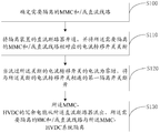
- FIG. 1 is a schematic structural diagram of an isolation device for a DC side of an MMC-HVDC system according to an embodiment of the present invention
- FIG. 2 is a schematic structural diagram of a current transfer switch for an isolation device on a DC side of an MMC-HVDC system according to an embodiment of the present invention
- FIG. 3 is a schematic structural diagram of a current transfer switch for an isolation device on a DC side of an MMC-HVDC system according to an embodiment of the present invention
- FIG. 4 is a schematic structural diagram of an auxiliary discharge branch for an isolation device on a DC side of an MMC-HVDC system according to an embodiment of the present invention
- FIG. 5 is a schematic structural diagram of a DC circuit breaker for an isolation device on a DC side of an MMC-HVDC system according to an embodiment of the present invention
- FIG. 6 is another schematic structural diagram of a DC circuit breaker for an isolation device on a DC side of an MMC-HVDC system according to an embodiment of the present invention
- FIG. 7 is a schematic structural diagram of an MMC-HVDC system according to an embodiment of the present invention.
- FIG 8 is another schematic structural diagram of an MMC-HVDC system according to an embodiment of the present invention.
- FIG. 9 is a schematic diagram of a DC power transmission system using four MMCs according to an embodiment of the present invention.
- FIG. 10 is a flowchart of an isolation method for a DC side of an MMC-HVDC system according to an embodiment of the present invention
- FIG. 11 is another flowchart of an isolation method for a DC side of an MMC-HVDC system according to an embodiment of the present invention.
- FIG. 12 is a flowchart of a method for further discharging redundant power in an isolation method on a DC side of an MMC-HVDC system according to an embodiment of the present invention.
- FIG. 1 is a schematic structural diagram of an isolation device for a DC side of an M MC-HVDC system according to an embodiment of the present invention. Only one DC circuit breaker is needed, and the MMC and multiple DC circuits and the MMC-HVDC system can be realized. Isolation, at the same time, the current transfer switch connected to the MMC and each DC line is cheaper than the DC circuit breaker, which saves the investment cost of the power grid to some extent.
- the isolation device 1 may include: a first isolation switch 100 a current transfer switch 200, an input and output terminal 300, and a DC circuit breaker 400; wherein
- One end of the DC circuit breaker 400 is grounded, and the other end is connected to all of the first isolation switches 100.
- the DC circuit breaker 400 is in the off state; when the MMC and/or DC lines in the MMC-HVDC system fail, or the MMC-HVDC system is required
- the DC circuit breaker 400 is placed in the on state, when the MMC and/or the need to isolate the MMC and/or
- the first isolation switch 100 corresponding to the DC line is disconnected, redundant power in the system will flow out through the DC circuit breaker 400 to ensure safe operation of the MMC-HVDC system.
- Each of the first isolation switches 100 is connected to an input and output terminal 300 through a current transfer switch 200, respectively.
- the first isolation switch 100 When the MMC-HVDC system works normally, there is no need to isolate the MMC and DC lines therein, the first isolation switch 100 is in the closed state, and the current transfer switch 200 is in the on state; when the MMC and/or DC lines in the MMC-HVDC system need to be performed In the case of isolation, the current transfer switch 200 corresponding to the isolated MMC and/or DC line is turned off, and when the current flowing through the turned-off current transfer switch 200 is zero, the current is switched off. The first isolation of the switch 200 is connected Off 100 is disconnected.
- the first isolation switch 100 can be an ultra-fast mechanical isolation switch with an isolation action of 2 ms (milliseconds).
- the current transfer switch 200 includes a first IGBT group 210 and a first arrester 220.
- the first IGBT group 210 and the first arrester 220 are connected in parallel.
- the first IGBT group 210 includes N first IGBTs with anti-parallel diodes and N second IGBTs with anti-parallel diodes, the first IGBT and the second IGBT being connected in reverse series.
- the current flowing through the current transfer switch 200 will flow from the IGBT tube collector of the first IGBT to the emitter, and from the diode anode of the second IGBT to the negative electrode.
- the state in which the current transfer switch 200 is in the on state means that all the IGBT tubes of the first IGBT group 210 in the current transfer switch 200 are in an on state.
- the current transfer switch 200 is in an off state, which refers to the current transfer switch 200. All of the IGBT tubes of the first IGBT group 210 are in an off state.
- the number of the first IGBT and the second IGBT in the first IGBT group in the current transfer switch 200 is N ⁇ kU 0 /U 1 , N ⁇ Z.
- k is the redundancy factor
- U 0 is the protection level of the first arrester 220
- U 1 is the bearing pressure of the first IGBT and the second IGBT in the first IGBT group 210.
- FIG. 3 another schematic diagram of a current transfer switch 200 of an isolation device according to an embodiment of the present invention includes a H-bridge set 230 and a first arrester 220.
- the H-bridge set 230 and the first arrester 220 are connected in parallel.
- the H-bridge group 230 includes N mutually connected H-bridge circuits 231, each of which includes a first capacitor and four third IGBTs with anti-parallel diodes.
- each H-bridge circuit 231 includes four bridge arms, and each bridge arm includes one with an anti-parallel diode.
- the third IGBT is used as the crossbar portion of the H-bridge circuit 231.
- the current transfer switch 200 is in the on state, that is, all the IGBT tubes of the H-bridge group 230 in the current transfer switch 200 are in an open state.
- the current transfer switch 200 is in an off state, which means that the current transfer switch 200 is in the H state. All IGBT tubes of bridge group 230 are in an off state.
- the number of the third IGBTs in the current transfer switch 200 is N ⁇ kU 0 /U 1 , N ⁇ Z.
- k is the redundancy factor
- U 0 is the protection level of the first arrester 220
- U 1 is the bearing pressure of the third IGBT in the H-bridge circuit 231.
- an MMC-HVDC system and an isolation device and an isolation method for the MMC-HVDC system are provided in an embodiment of the present invention, wherein the isolation device includes a first isolation switch, a current transfer switch, an input and output terminal, and A DC circuit breaker having one end grounded and the other end connected to all of the first isolating switches, each of the first isolating switches being connected to an input and output through a current transfer switch.
- the current transfer switch includes a first arrester and a first IGBT group or an H-bridge group connected in parallel with the first arrester, and the first IGBT group connected in parallel with the first arrester is N
- the first IGBT with the anti-parallel diode and the second IGBT with the reverse parallel diode are connected in reverse series
- the H-bridge group connected in parallel with the first arrester is composed of N H-bridge circuits connected in series
- each The H-bridge circuit includes a first capacitor and four third IGBTs with anti-parallel diodes, wherein N ⁇ kU 0 /U 1 , N ⁇ Z,k are redundancy coefficients, and U 0 is protection of the first arrester Level
- U 1 is the pressure of the first IGBT and the second IGBT or the pressure of the third IGBT
- the isolation device for the DC side of the MMC-HVDC system may further include a second isolation switch 500, each of which can pass through the second isolation switch 500 and all The first isolation switch 100 is connected.
- the second isolation switch 500 When the MMC-HVDC system works normally, there is no need to isolate the MMC and DC lines therein, the second isolation switch 500 is in a closed state; when it is necessary to isolate the MMC and/or DC lines in the MMC-HVDC system, isolation will be required. MMC and / or DC line and MMC-HVDC system After isolation, when the current flowing through the DC breaker 400 is detected to be 0, the redundant current can be further discharged and discharged by disconnecting the second isolation 500 switch.
- the isolation device for the DC side of the MMC-HVDC system may further include an auxiliary discharge branch 600, one end of each auxiliary discharge branch 600 is grounded, and the other end is connected with an input.
- the output terminals 300 are connected such that the auxiliary discharge branch 600 assists the DC circuit breaker 400 in discharging redundant power.
- FIG. 4 is a schematic structural diagram of an auxiliary discharge branch 600 for an isolation device on a DC side of an MMC-HVDC system according to an embodiment of the present invention.
- the auxiliary discharge branch 60 may include: auxiliary Discharge switch 610 and resistor 620.
- the auxiliary discharge switch 610 and the resistor 620 are connected in series.
- the auxiliary discharge switch 610 includes a thyristor group 611 and a second arrester 612.
- the thyristor group 611 and the second arrester 612 are connected in parallel.
- the thyristor group 611 includes a thyristor, and all the thyristors are connected in series.
- the auxiliary discharge switch 610 is in an open state, which means that all the thyristors in the auxiliary discharge switch 610 are in an open state.
- the auxiliary discharge switch 610 is in an off state, which means that all the thyristors in the auxiliary discharge switch 610 are in an off state. .
- the auxiliary discharge switch 610 When the MMC-HVDC system works normally, there is no need to isolate the MMC and DC lines therein, the auxiliary discharge switch 610 is in the off state; when it is necessary to isolate the MMC and/or DC lines in the MMC-HVDC system, it will be necessary to assist The discharge switch 610 is turned on to turn the auxiliary discharge switch 610 into an on state.
- the positive electrode of the thyristor group 611 should be used as the high voltage end of the auxiliary discharge switch 610, and the negative electrode of the thyristor group 611 should be used as the auxiliary discharge switch 610.
- the low voltage end that is, the positive poles of all the thyristors in the thyristor group 611 are connected to one end of the input and output end 300, that is, the end away from the ground end, and the negative poles of all the thyristors in the thyristor group 611 are connected to the end away from the input and output end 300, that is, Near one end of the ground terminal, when the auxiliary discharge switch 610 is in the on state, current can flow from the positive electrode of the thyristor to the negative electrode.
- FIG. 5 and FIG. 6 are schematic diagrams showing two structures of the DC circuit breaker 400 for the DC side isolation device of the MMC-HVDC system according to an embodiment of the present invention.
- the device 400 may include a switching unit 410, and the respective switching units 410 are connected in series.
- the switch unit 410 may include a second IGBT group 411 and a third lightning protection
- the second IGBT group 411 and the third arrester 412 are connected in parallel
- the second IGBT group 411 is composed of at least one fourth IGBT with an anti-parallel diode
- all of the fourth IGBTs with anti-parallel diodes are connected in series.
- the DC circuit breaker 400 is in an open state, which means that all the IGBT tubes of the second IGBT group 411 in the DC circuit breaker 400 are in an open state
- the DC circuit breaker 400 is in an off state, which refers to a second IGBT in the DC circuit breaker 400. All IGBT tubes of group 411 are in an off state.
- the collector of the second IGBT group 411 is used as the high voltage end of the switching unit 410, and the emitter of the second IGBT group 411 is used as the emitter.
- the low voltage end of the switching unit 410 that is, the collectors of all the fourth IGBTs in the second IGBT group 411 are connected to one end close to the first isolation switch 100, that is, one end away from the ground end, and all the fourth in the second IGBT group 411
- the emitter of the IGBT is connected to an end remote from the first isolation switch 100, that is, an end close to the ground, so that when the DC breaker 400 is in an on state, current can flow from the collector of the fourth IGBT to the emitter.
- the switch unit 410 may include a half H bridge group 413 and a third lightning arrester 412.
- the half H bridge group 413 and the third lightning arrester 412 are connected in parallel, and the half H bridge group 413 is composed of at least one half H bridge circuit. All half-H bridge circuits are connected in series.
- the half H bridge group 413 includes at least one half H bridge circuit connected in series, and each half H bridge circuit includes one second capacitor and two fifth IGBTs with antiparallel diodes.
- the collector of one of the two fifth IGBTs is used as the high voltage end of the half H bridge circuit
- the emitter stage is used as the low voltage end of the half H bridge circuit, so that when the DC circuit breaker 400 is in the on state, the current can be
- the collector of the IGBT flows to the emitter, and the collector of the IGBT is connected to the emitter of the other IGBT, the emitter stage is connected to one end of the second capacitor, and the other end of the second capacitor is connected to the collector of the other IGBT .
- the DC circuit breaker 400 is in an open state, which means that all the IGBT tubes of the half H bridge group 413 in the DC circuit breaker 400 are in an open state, and the DC circuit breaker 400 is in an off state, which refers to a half H bridge in the DC circuit breaker 400. All IGBT tubes of group 413 are in an off state.
- Optional can pass N s ⁇ Z, to determine the number N s of switching units 410 used by the DC circuit breaker 400.
- k is the redundancy factor
- k 1 is the overvoltage withstand factor
- U dc is the DC voltage
- U e is the protection level of the third arrester 412.
- Optional can pass N e ⁇ Z, to determine the number of third IGBTs with anti-parallel diodes used in the second IGBT group 411 or to determine the number of half-H bridge circuits used in the half-H bridge group 413.
- U e is the protection level of the third arrester 412
- U i is the pressure of the fourth IGBT or the fifth IGBT.
- the switch unit 410 includes the second IGBT group 411 and the third arrester 412
- U i is the pressure of the fourth IGBT.
- the switch unit 410 includes the half H bridge group 413 and the third arrester 412
- U i is The pressure of the fifth IGBT.
- the DC circuit breaker 400 when it is required to isolate the MMC and/or the DC line in the MMC-HVDC system, the DC circuit breaker 400 is controlled to be in an open state, and the current transfer switch 200 and the first connected to the MMC or the DC line respectively An isolation switch 100 is respectively turned off and off, so that the isolated MMC and/or DC line is isolated from the MMC-HVDC system, and after detecting that the first isolation switch 100 is completely closed, the DC circuit breaker 400 is turned off, that is, All of the third IGBTs in the DC circuit breaker 400 are turned off, and the remaining redundant power is further discharged through the third arrester 412 of the DC circuit breaker 400.
- the isolation device for the DC side of the MMC-HVDC system may further include a DC bus 700 , and the DC circuit breaker 400 may be connected to all the first isolation switches 100 through the DC bus 700 . .
- the isolation device for the DC side of the MMC-HVDC system provided by the embodiment of the present invention can only isolate the MMC and the multiple DC circuits from the MMC-HVDC system by using one DC circuit breaker, and with the MMC and each The cost of multiple current transfer switches connected by DC lines is lower than that of DC circuit breakers, which saves the investment cost of the power grid to some extent.
- the MMC-HVDC system provided by the embodiment of the present invention is described below.
- the MMC-HVDC system described below includes the above-described isolation device for the DC side of the MMC-HVDC system.
- FIG. 7 is a schematic structural diagram of an MMC-HVDC system according to an embodiment of the present invention.
- the MMC-HVDC system may include: MMC1, a DC line 2, and an isolation device 3, and both the MMC1 and the DC line 2 are isolated from the device. The input and output terminals of 3 are connected.
- each MMC-HVDC system includes one MMC1 and a plurality of DC lines 2, and each MMC1 is connected to the DC line 2.
- the MMC1 converts the AC power into DC power and outputs it to the current line 2, and then the DC line 2 transmits the received DC power; or the DC line 2 transmits the DC power to the MMC1, and the MMC1
- the received DC power is converted to AC power and output to the AC side of the system.
- the MMC1 and the DC line 2 are both connected to the input and output ends of the isolation device 3, that is, after the MMC1 and the DC line 2 are connected through the isolation device 3, when the DC circuit breaker of the isolation device 3 is turned on, and the current transfer switch of the isolation device 3 is turned off.
- the first isolating switch connected to the turned off current transfer switch is disconnected, the redundant power of the MMC-HVDC will flow out from the DC circuit breaker of the isolating device 3, and the turned off current transfer switch corresponds to the MMC1 or The DC line 2 will be isolated from the MMC-HVDC system.
- the MMC and/or DC lines in the MMC-HVDC system when it is necessary to isolate the MMC and/or DC lines in the MMC-HVDC system, such as when the MMC and/or DC lines in the MMC-HVDC system fail, or the MMC and / in the MMC-HVDC system are required. Or when the DC line is being repaired.
- the need can be made by turning on the DC circuit breaker of the isolation device 3 and turning off and disconnecting the corresponding current transfer switch and the first isolation switch in the isolation device 3 of the MMC1 and/or DC line 2 that need to be isolated, respectively.
- the isolated MMC1 and/or DC line 2 is physically isolated from the MMC-HVDC system, and the redundant power of the MMC-HVDC system is discharged from the DC circuit breaker of the isolation device 3 to cause the MMC1 and/or DC line to be isolated. 2 will be isolated from the MMC-HVDC system.
- FIG. 8 is another schematic structural diagram of an MMC-HVDC system provided by an embodiment of the present invention.
- the MMC-HVDC system may further include: a smoothing reactor 4, and the MMC1 may pass a flat wave.
- the reactor 4 is connected to the input and output terminals of the isolation device 3.
- the smoothing reactor 4 it is possible to suppress the ripple in the direct current passing through the smoothing reactor 4 and suppress the rise of the short-circuit current.
- a multi-terminal MMC-HVDC system that is, a DC power transmission system using more than two MMCs, for example, a DC power transmission system using four MMCs provided by the embodiment of the present invention shown in FIG. 9 corresponds to one MMC per MMC.
- -HVDC system referring to Figure 9, the four MMC DC transmission systems, including four MMCs, four isolation devices and five DC lines, each MMC is connected to an isolation device, each isolation device All DC lines in the MMC-HVDC system are connected.
- the first isolation switch in the isolation device in the system is in a closed state
- the current conversion switch is in an on state
- the DC circuit breaker is in In the off state
- the second isolation switch is in a closed state
- the auxiliary discharge switch of the auxiliary discharge branch is in an off state.
- the isolation device I and the The isolation device II simultaneously performs an isolation operation to isolate the DC line 12 from the MMC-HVDC system in which the isolation device I and the isolation device II are located, thereby isolating the DC line 12 from the DC transmission system.
- the isolation devices Taking one of the isolation devices as an example, the DC circuit breaker in the isolation device can be turned off, and then the current conversion switch is turned off.
- the first disconnecting switch connected to the shut-off current transfer switch is disconnected, so that the redundant electric energy of the MMC-HVDC system where the isolating device is located flows out from the DC circuit breaker and the auxiliary discharging branch, so that the faulty DC line 12 is The MMC-HVDC system where the isolation device is located is isolated.
- the auxiliary discharge switch and the DC circuit breaker of the auxiliary discharge branch in the isolation device can be simultaneously turned on at the same time, so that the auxiliary DC circuit breaker of the auxiliary discharge branch is redundant.
- the flow of electrical energy After detecting that the first isolation switch is completely disconnected, the DC circuit breaker can be controlled to be turned off, so that the remaining redundant electric energy is further discharged and discharged through the third arrester of the DC circuit breaker.
- the second isolation switch of the isolation device can be disconnected, so that the redundant current is further discharged and discharged.
- the MMC-HVDC system provided by the embodiment of the present invention, only one isolation device needs to be configured for each MMC, and only one DC circuit breaker is needed for each isolation device, so that the MMC and multiple DC circuits and the MMC-HVDC system can be realized. Isolation, and multiple currents connected to the MMC and each DC line The cost of the shift switch is lower than that of the DC circuit breaker, which saves the investment cost of the power grid to some extent.
- the following describes an isolation method for the DC side of the MMC-HVDC system provided by the embodiment of the present invention.
- the isolation method for the DC side of the MMC-HVDC system described below is based on the MMC-HVDC system described above, the MMC-HVDC system DC.
- the side isolation method can be applied to the MMC-HVDC system to isolate the MMC and/or DC lines that need to be isolated in the MMC-HVDC system from the MMC-HVDC system.
- the isolation method includes:
- Step S100 determining an MMC and/or a DC line that needs to be isolated
- the MMC and/or DC line in the MMC-HVDC system fails or the MMC and/or DC lines in the MMC-HVDC system need to be overhauled, the MMC and/or the DC in the MMC-HVDC system are required.
- the lines are isolated. In the case of MMC and/or DC lines in the MMC-HVDC system, it is necessary to first determine the MMC and/or DC lines that need to be isolated.
- the isolation is MMC.
- MMC-HVDC multi-terminal MMC-HVDC
- Step S110 Turn on the DC circuit breaker of the isolation device, and turn off the current transfer switch corresponding to the MMC and/or DC line that needs to be isolated;
- the DC circuit breaker in the isolation device to which the isolated MMC and/or DC line is connected is turned on, and the isolated MMC and/or the isolated device are required to be isolated.
- the current transfer switch corresponding to the DC line is turned off.
- the DC circuit breaker of the isolation device should be turned on first, and then the current transfer switch corresponding to the MMC and/or the DC line to be isolated is turned off.
- Step S120 when the current flowing through the turned off current transfer switch is zero, disconnecting the first isolation switch connected to the turned off current transfer switch;
- the current flowing through the turned-off current transfer switch will gradually decrease, and when the current flowing through the turned-off current transfer switch is zero, the current will be turned off.
- the first disconnecting switch connected to the transfer switch is disconnected.
- Step S130 The redundant electric energy of the MMC-HVDC flows out from the DC circuit breaker, and the MMC and/or DC line to be isolated is isolated from the MMC-HVDC system.
- the redundant power of the MMC-HVDC will flow out from the DC circuit breaker, which is required.
- the isolated MMC and/or DC line is isolated from the MMC-HVDC system in which it is located.
- FIG. 11 is another flowchart of an isolation method for a DC side of an MMC-HVDC system according to an embodiment of the present invention.
- the isolation method may include:
- Step S200 determining an MMC and/or a DC line that needs to be isolated
- Step S210 Turn on the DC circuit breaker of the isolation device, and turn on the auxiliary discharge switch of the auxiliary discharge branch of the isolation device;
- the isolation device includes an auxiliary DC circuit breaker for auxiliary power supply branching
- the auxiliary discharge switch and the DC circuit breaker in the auxiliary discharge branch should be simultaneously Turning on, the auxiliary discharge branch 600 assists the DC circuit breaker 400 in discharging redundant power.
- Step S220 Turn off the current transfer switch corresponding to the MMC and/or DC line that needs to be isolated;
- the auxiliary discharge switch and the DC circuit breaker in the auxiliary discharge branch of the isolation device should be opened first, and then the MMC and/or DC line to be isolated should be corresponding.
- the current transfer switch is turned off.
- Step S230 when the current flowing through the turned off current transfer switch is zero, disconnecting the first isolation switch connected to the turned off current transfer switch;
- Step S240 The redundant power of the MMC-HVDC flows out from the DC circuit breaker, and the MMC and/or DC line that needs to be isolated is isolated from the MMC-HVDC system;
- FIG. 12 is a flowchart of a method for further discharging redundant power in the isolation method provided by the embodiment of the present invention.
- the method for further discharging redundant power may include:
- Step S300 turning off the DC circuit breaker of the isolation device
- the DC circuit breaker After detecting that the first isolation switch in the isolation device is completely disconnected, the DC circuit breaker can be controlled to be turned off, so that the remaining redundant power is further discharged and discharged through the lightning arrester of the DC circuit breaker.
- Step S310 When the current flowing through the DC circuit breaker is zero, the second isolation switch of the isolation device is disconnected.
- the second isolation switch of the isolation device can be disconnected to make the redundant The current is further discharged and discharged.
- the isolation method provided by the embodiment of the present invention is used for the MMC-HVDC system, specifically, for the DC side of the MMC-HVDC system, each MMC only needs to be configured with one isolation device, and each isolation device only needs one DC open circuit.
- the MMC and multiple DC circuits can be isolated from the MMC-HVDC system, and the multiple current transfer switches connected to the MMC and each DC line are cheaper than the DC circuit breaker, which saves the grid to some extent. cost of investment.
Abstract
An MMC-HVDC system, and a direct-current side isolation device and an isolation method therefor. The isolation device comprises: a first isolation switch, a current transfer switch, an input/output end and a direct-current breaker. One end of the direct-current breaker is grounded, while the other end is connected to all the first isolation switches, and each of the first isolation switches is respectively connected to an input/output end via the current transfer switch. The current transfer switch comprises: a first lightning arrester and a first IGBT group or an H-bridge group connected to the first lightning arrester in parallel. The first IGBT group consists of N first IGBTs and N second IGBTs. The H-bridge group comprises N H-bridge circuits which are connected in series, and each of the H-bridge circuits comprises one first capacitor and four third IGBTs, where N ≥ kU0/U1, and N ∈ Z. The invention can realize the isolation of an MMC and a plurality of direct-current circuits from the MMC-HVDC system, thereby saving on the investment costs of a power grid.
Description
本申请要求于2015年8月7日提交中国专利局、申请号为201510483656.8、发明名称为“一种MMC-HVDC系统及其直流侧隔离装置和隔离方法”的中国专利申请的优先权,其全部内容通过引用结合在本申请中。This application claims priority to Chinese Patent Application No. 201510483656.8, entitled "A MMC-HVDC System and Its DC Side Isolation Device and Isolation Method", filed on August 7, 2015. The content is incorporated herein by reference.
本发明涉及电力系统控制技术领域,特别是涉及一种MMC-HVDC系统及其直流侧隔离装置和隔离方法。The invention relates to the technical field of power system control, in particular to an MMC-HVDC system and a DC side isolation device and an isolation method thereof.
为了解决新能源并网与消纳问题,基于电压源换流器(voltage source converter,VSC)的高压直流输电(high-voltage direct current,HVDC)技术和直流电网技术已经成为学术研究的热点。相比与传统的交流输电技术以及基于电网换相换流器的高压直流输电技术,基于VSC-HVDC不但具有线路损耗低、传输容量大、传输距离远等优点,而且不存在系统同步运行稳定性问题,可以充分提高可再生能源的利用率。In order to solve the problem of grid connection and consumption of new energy sources, high voltage direct current (HVDC) technology and DC grid technology based on voltage source converter (VSC) have become a hot topic in academic research. Compared with traditional AC transmission technology and high-voltage DC transmission technology based on grid commutator, VSC-HVDC has the advantages of low line loss, large transmission capacity and long transmission distance, and there is no system synchronous operation stability. The problem can fully improve the utilization rate of renewable energy.
在众多拓扑结构中,基于模块化多电平换流器(modular multilevel converter,MMC)的HVDC具有显著优势,MMC拓扑采用子模块级联的方式构成,避免了绝缘栅双极型晶体管(Insulated Gate Bipolar Transistor,IGBT)的直接串联,大大降低了其制造难度。此外,它还具有交流输出电压谐波畸变率低、开关损耗小等优点,更适合于构建高压直流输电系统以及直流电网,具有广阔的应用前景。Among many topologies, HVDC based on modular multilevel converter (MMC) has significant advantages. The MMC topology is constructed by sub-module cascade, which avoids insulated gate bipolar transistors (Insulated Gate). The direct series connection of Bipolar Transistor (IGBT) greatly reduces the manufacturing difficulty. In addition, it also has the advantages of low harmonic distortion rate and low switching loss of AC output voltage, and is more suitable for constructing HVDC transmission system and DC grid, which has broad application prospects.
在现有MMC-HVDC工程中,通常通过在MMC-HVDC系统的MMC和每条直流线路上均引入直流断路器,通过关断某直流断路器来使与该直流断路器相连的MMC或直流线路与该MMC-HVDC系统隔离。由于现有MMC-HVDC工程中换流器多采用半桥子模块(half bridge sub-module,HBSM),而HBSM不具有直流故障自清除能力,因此,可以通过在MMC-HVDC系统的MMC和每条直流线路上均引入直流断路器,通过直流断
路器使故障MMC和/或故障直流线路与该MMC-HVDC系统隔离,来清除该MMC-HVDC系统的直流故障。然而,由于直流断路器的造价昂贵,通过在MMC-HVDC系统的MMC和每条直流线路上均引入直流断路器来隔离MMC和/或直流线路,将使用到大量的直流断路器,而随着网状结构逐渐成为主流,MMC-HVDC系统中使用的直流线路的逐渐增加,所需要安装使用的直流断路器的数目也随之而增加,这将在一定程度上增加电网的投资成本,造成电网的投资成本过高的问题。In the existing MMC-HVDC project, a DC circuit breaker is usually introduced in the MMC of the MMC-HVDC system and each DC line, and the MMC or DC line connected to the DC circuit breaker is turned off by turning off a DC circuit breaker. Isolated from the MMC-HVDC system. Since the inverters in the existing MMC-HVDC project mostly use a half bridge sub-module (HBSM), and the HBSM does not have the DC fault self-clearing capability, it can pass the MMC and each in the MMC-HVDC system. DC circuit breakers are introduced on the DC lines, and DC breakers are used.
The router isolates the faulty MMC and/or the faulty DC line from the MMC-HVDC system to clear the DC fault of the MMC-HVDC system. However, due to the high cost of DC circuit breakers, a large number of DC circuit breakers will be used by isolating the MMC and/or DC lines by introducing a DC circuit breaker on the MMC of the MMC-HVDC system and each of the DC lines. The mesh structure has gradually become the mainstream. The number of DC lines used in the MMC-HVDC system has gradually increased, and the number of DC circuit breakers that need to be installed and used has also increased. This will increase the investment cost of the power grid to a certain extent, resulting in the power grid. The problem of excessive investment costs.
发明内容Summary of the invention
有鉴于此,本发明实施例提供一种MMC-HVDC系统及其直流侧隔离装置和隔离方法,以解决现有技术中通过在MMC-HVDC系统的MMC和每条直流线路上均引入直流断路器来隔离MMC和/或直流线路,在一定程度上增加电网的投资成本,造成电网的投资成本过高的问题。In view of this, an embodiment of the present invention provides an MMC-HVDC system, and a DC-side isolation device and an isolation method thereof, to solve the problem of introducing a DC circuit breaker in the MMC of the MMC-HVDC system and each DC line in the prior art. To isolate the MMC and / or DC lines, to some extent increase the investment cost of the grid, resulting in the problem of excessive investment costs of the grid.
为实现上述目的,本发明实施例提供如下技术方案:To achieve the above objective, the embodiment of the present invention provides the following technical solutions:
一种用于MMC-HVDC系统直流侧的隔离装置,包括:第一隔离开关、电流转移开关、输入输出端和一直流断路器;其中,An isolation device for a DC side of an MMC-HVDC system, comprising: a first isolation switch, a current transfer switch, an input and output terminal, and a DC current circuit breaker; wherein
所述直流断路器的一端接地,另一端与所有所述第一隔离开关均相连;每个所述第一隔离开关分别通过所述电流转移开关与一输入输出端相连;One end of the DC circuit breaker is grounded, and the other end is connected to all of the first isolation switches; each of the first isolation switches is connected to an input and output end through the current transfer switch;
所述电流转移开关包括:第一避雷器和与所述第一避雷器并联连接的第一IGBT组或H桥组,所述第一IGBT组包括N个带反向并联二极管的第一IGBT和N个带反向并联二极管的第二IGBT,所述第一IGBT和所述第二IGBT反向串联连接;所述H桥组包括N个相互串联的H桥电路,每个所述H桥电路包括1个第一电容和4个带反向并联二极管的第三IGBT;The current transfer switch includes: a first arrester and a first IGBT group or an H-bridge group connected in parallel with the first arrester, the first IGBT group including N first IGBTs and N-bands with anti-parallel diodes a second IGBT with an anti-parallel diode, the first IGBT and the second IGBT are connected in reverse series; the H-bridge group includes N H-bridge circuits connected in series, each of the H-bridge circuits including 1 a first capacitor and four third IGBTs with anti-parallel diodes;
其中,N≥kU0/U1,N∈Z,k为冗余系数,U0为所述第一避雷器的保护水平,U1为所述第一IGBT和所述第二IGBT的承压或为所述第三IGBT的承压。Where N ≥ kU 0 / U 1 , N ∈ Z, k is a redundancy coefficient, U 0 is the protection level of the first arrester, and U 1 is the pressure of the first IGBT and the second IGBT or It is the pressure of the third IGBT.
其中,所述隔离装置还包括:第二隔离开关,每个所述直流断路器分别通过所述第二隔离开关与所有所述第一隔离开关相连。The isolation device further includes: a second isolation switch, each of the DC circuit breakers being connected to all of the first isolation switches by the second isolation switch.
其中,所述隔离装置还包括:辅助放电支路,每个所述辅助放电支路的一端接地,另一端与一所述输入输出端相连;
The isolation device further includes: an auxiliary discharge branch, one end of each of the auxiliary discharge branches is grounded, and the other end is connected to one of the input and output ends;
所述辅助放电支路包括:串联连接的辅助放电开关和电阻器,所述辅助放电开关包括相互并联的晶闸管组和第二避雷器,所述晶闸管组包括至少一个相互串联的晶闸管,当所述辅助放电开关处于开通状态时,电流从所述晶闸管的正极流向负极。The auxiliary discharge branch includes: an auxiliary discharge switch and a resistor connected in series, the auxiliary discharge switch includes a thyristor group and a second arrester connected in parallel, the thyristor group including at least one thyristor connected in series, when the auxiliary When the discharge switch is in the on state, current flows from the positive electrode of the thyristor to the negative electrode.
其中,所述直流断路器包括至少一个相互串联的开关单元,所述开关单元包括第三避雷器和与所述第三避雷器并联连接的第二IGBT组或半H桥组,所述第二IGBT组包括至少一个相互串联的带反向并联二极管的第四IGBT,所述半H桥组包括至少一个相互串联的半H桥电路,每个所述半H桥电路包括1个第二电容和2个带反向并联二极管的第五IGBT,当所述直流断路器处于开通状态时,电流从所述第四IGBT或所述第五IGBT的集电极流向发射极;The DC circuit breaker includes at least one switching unit connected in series, the switching unit includes a third arrester and a second IGBT group or a half H bridge group connected in parallel with the third arrester, the second IGBT group A fourth IGBT having at least one antiparallel diode connected in series, the half H bridge group including at least one half H bridge circuit connected in series, each of the half H bridge circuits including one second capacitor and two a fifth IGBT with an anti-parallel diode, when the DC circuit breaker is in an on state, current flows from the collector of the fourth IGBT or the fifth IGBT to the emitter;
其中,所述开关单元的数目 Ns∈Z;Wherein the number of the switching units N s ∈Z;
所述第三IGBT的数目 Ne∈Z;Number of the third IGBT N e ∈Z;
其中,k为冗余系数,k1为过电压可承受系数,Udc为直流电压,Ue为所述第三避雷器的保护水平,Ui为所述第四IGBT或所述第五IGBT的承压。Where k is the redundancy factor, k 1 is the overvoltage withstand factor, U dc is the DC voltage, U e is the protection level of the third arrester, and U i is the fourth IGBT or the fifth IGBT Under pressure.
其中,所述隔离装置还包括:直流母线,所述直流断路器通过所述直流母线与所有所述第一隔离开关均相连。The isolation device further includes: a DC bus, and the DC circuit breaker is connected to all of the first isolation switches through the DC bus.
一种MMC-HVDC系统,包括:MMC、直流线路和上述的隔离装置;其中,An MMC-HVDC system comprising: an MMC, a DC line, and the above-mentioned isolation device; wherein
所述MMC和所述直流线路均与所述隔离装置的输入输出端相连;The MMC and the DC line are both connected to an input and output end of the isolation device;
当所述隔离装置的直流断路器开通,且所述隔离装置的电流转移开关关断,与所述关断的电流转移开关相连的第一隔离开关断开时,所述MMC-HVDC的冗余电能从所述直流断路器流出,所述关断的电流转移开关相对应的MMC或直流线路与所述MMC-HVDC系统隔离。When the DC circuit breaker of the isolation device is turned on, and the current transfer switch of the isolation device is turned off, and the first isolation switch connected to the shutdown current transfer switch is disconnected, the redundancy of the MMC-HVDC Electrical energy flows from the DC circuit breaker, and the corresponding MMC or DC line of the turned off current transfer switch is isolated from the MMC-HVDC system.
其中,所述MMC-HVDC系统还包括:平波电抗器,所述MMC通过所述平波电抗器与所述隔离装置的输入输出端相连。The MMC-HVDC system further includes: a smoothing reactor, wherein the MMC is connected to the input and output ends of the isolation device through the smoothing reactor.
一种用于MMC-HVDC系统直流侧的隔离方法,基于上述的MMC-HVDC系统,其特征在于,包括:
An isolation method for a DC side of an MMC-HVDC system, based on the MMC-HVDC system described above, comprising:
确定需要隔离的MMC和/或直流线路;Identify the MMC and/or DC lines that need to be isolated;
将隔离装置的直流断路器开通,并将所述需要隔离的MMC和/或直流线路相对应的电流转移开关关断;Turning on the DC circuit breaker of the isolation device, and turning off the current transfer switch corresponding to the MMC and/or DC line to be isolated;
当流过所述关断的电流转移开关的电流为零时,将与所述关断的电流转移开关相连的第一隔离开关断开,所述MMC-HVDC的冗余电能从所述直流断路器流出,所述需要隔离的MMC和/或直流线路与所述MMC-HVDC系统隔离。When the current flowing through the turned-off current transfer switch is zero, the first isolation switch connected to the turned-off current transfer switch is disconnected, and the redundant power of the MMC-HVDC is disconnected from the DC The device flows out, and the MMC and/or DC line that needs to be isolated is isolated from the MMC-HVDC system.
其中,所述确定需要隔离的MMC或直流线路后还包括:将所述隔离装置辅助放电支路的辅助放电开关开通,将所述隔离装置辅助放电支路的辅助放电开关和所述隔离装置的直流断路器均开通后,将所述需要隔离的MMC和/或直流线路相对应的电流转移开关关断。After the determining the MMC or the DC line to be isolated, the method further includes: opening an auxiliary discharge switch of the auxiliary discharge branch of the isolation device, and auxiliary discharge switch of the auxiliary discharge branch of the isolation device and the isolation device After the DC circuit breakers are all turned on, the current transfer switch corresponding to the MMC and/or DC line to be isolated is turned off.
其中,所述需要隔离的MMC和/或直流线路与所述MMC-HVDC系统隔离后还包括:The isolation of the MMC and/or DC line that needs to be isolated from the MMC-HVDC system further includes:
将所述隔离装置的直流断路器关断;Turning off the DC circuit breaker of the isolation device;
当流过所述直流断路器的电流为零时,将所述隔离装置的第二隔离开关断开。The second isolating switch of the isolating device is opened when the current flowing through the DC circuit breaker is zero.
基于上述技术方案,本发明实施例提供的一种MMC-HVDC系统和用于该MMC-HVDC系统的隔离装置及隔离方法,其中,隔离装置包括第一隔离开关、电流转移开关、输入输出端和一直流断路器,该直流断路器的一端接地,另一端与所有第一隔离开关均相连,每个第一隔离开关均通过一个电流转移开关与一输入输出端相连。当需要将某直流线路或是MMC与MMC-HVDC系统进行隔离时,通过将直流断路器开通,并将与该MMC或该直流线路相连的电流转移开关和第一隔离开关分别关闭和断开后,该MMC或该直流线路与MMC-HVDC系统物理隔离,同时因为MMC和/或直流线路与系统的物理隔离,系统冗余的电能将通过该直流断路器泄放流出,至此,便可实现该MMC或该直流线路与MMC-HVDC系统的完全安全隔离,只需要使用一台直流断路器,便可实现将MMC和多条直流电路与MMC-HVDC系统的隔离。同时,本发明实施例提供的隔离装置中电流转移开关包括第一避雷器和与该第一避雷器并联连接的第一IGBT组或H桥组,与该第一避雷器并联的第一IGBT组由N个带反向并联二极管的第一IGBT和N个带反向并联二极管的第二IGBT反
向串联连接组成,与该第一避雷器并联的H桥组由N个相互串联的H桥电路组成,每个H桥电路包括1个第一电容和4个带反向并联二极管的第三IGBT,其中,N≥kU0/U1,N∈Z,k为冗余系数,U0为第一避雷器的保护水平,U1为第一IGBT和第二IGBT的承压或为第三IGBT的承压,可以看出,无论电流转移开关包括第一避雷器和第一IGBT组,还是包括第一避雷器和H桥组,与MMC和每条直流线路相连的电流转移开关造价均比直流断路器低廉,因此,使用本发明实施例提供的隔离装置将在一定程度上节省了电网的投资成本。Based on the foregoing technical solution, an MMC-HVDC system and an isolation device and an isolation method for the MMC-HVDC system are provided in an embodiment of the present invention, wherein the isolation device includes a first isolation switch, a current transfer switch, an input and output terminal, and A DC circuit breaker having one end grounded and the other end connected to all of the first isolating switches, each of the first isolating switches being connected to an input and output through a current transfer switch. When it is necessary to isolate a DC line or MMC from the MMC-HVDC system, the DC circuit breaker is turned on, and the current transfer switch and the first isolation switch connected to the MMC or the DC line are respectively turned off and on. The MMC or the DC line is physically isolated from the MMC-HVDC system, and because the MMC and/or the DC line are physically isolated from the system, the redundant power of the system is discharged through the DC circuit breaker, and thus the The MMC or the DC line is completely safely isolated from the MMC-HVDC system, and only one DC breaker can be used to isolate the MMC and multiple DC circuits from the MMC-HVDC system. Meanwhile, in the isolation device provided by the embodiment of the present invention, the current transfer switch includes a first arrester and a first IGBT group or an H-bridge group connected in parallel with the first arrester, and the first IGBT group connected in parallel with the first arrester is N The first IGBT with the anti-parallel diode and the second IGBT with the reverse parallel diode are connected in reverse series, and the H-bridge group connected in parallel with the first arrester is composed of N H-bridge circuits connected in series, each The H-bridge circuit includes a first capacitor and four third IGBTs with anti-parallel diodes, wherein N≥kU 0 /U 1 , N∈Z,k are redundancy coefficients, and U 0 is protection of the first arrester Level, U 1 is the pressure of the first IGBT and the second IGBT or the pressure of the third IGBT, it can be seen that whether the current transfer switch includes the first arrester and the first IGBT group, or includes the first arrester and the H-bridge The cost of the current transfer switch connected to the MMC and each of the DC lines is lower than that of the DC circuit breaker. Therefore, the use of the isolation device provided by the embodiment of the present invention will save the investment cost of the power grid to some extent.
为了更清楚地说明本发明实施例或现有技术中的技术方案,下面将对实施例或现有技术描述中所需要使用的附图作简单地介绍,显而易见地,下面描述中的附图仅仅是本发明的实施例,对于本领域普通技术人员来讲,在不付出创造性劳动的前提下,还可以根据提供的附图获得其他的附图。In order to more clearly illustrate the embodiments of the present invention or the technical solutions in the prior art, the drawings used in the embodiments or the description of the prior art will be briefly described below. Obviously, the drawings in the following description are only It is an embodiment of the present invention, and those skilled in the art can obtain other drawings according to the provided drawings without any creative work.
图1为本发明实施例提供的用于MMC-HVDC系统直流侧的隔离装置的结构示意图;1 is a schematic structural diagram of an isolation device for a DC side of an MMC-HVDC system according to an embodiment of the present invention;
图2为本发明实施例提供的用于MMC-HVDC系统直流侧的隔离装置的电流转移开关的结构示意图;2 is a schematic structural diagram of a current transfer switch for an isolation device on a DC side of an MMC-HVDC system according to an embodiment of the present invention;
图3为本发明实施例提供的用于MMC-HVDC系统直流侧的隔离装置的电流转移开关的结构示意图;3 is a schematic structural diagram of a current transfer switch for an isolation device on a DC side of an MMC-HVDC system according to an embodiment of the present invention;
图4为本发明实施例提供的用于MMC-HVDC系统直流侧的隔离装置的辅助放电支路的结构示意图;4 is a schematic structural diagram of an auxiliary discharge branch for an isolation device on a DC side of an MMC-HVDC system according to an embodiment of the present invention;
图5为本发明实施例提供的用于MMC-HVDC系统直流侧的隔离装置的直流断路器的结构示意图;5 is a schematic structural diagram of a DC circuit breaker for an isolation device on a DC side of an MMC-HVDC system according to an embodiment of the present invention;
图6为本发明实施例提供的用于MMC-HVDC系统直流侧的隔离装置的直流断路器的另一结构示意图;6 is another schematic structural diagram of a DC circuit breaker for an isolation device on a DC side of an MMC-HVDC system according to an embodiment of the present invention;
图7为本发明是实施例提供的MMC-HVDC系统的结构示意图;FIG. 7 is a schematic structural diagram of an MMC-HVDC system according to an embodiment of the present invention;
图8为本发明是实施例提供的MMC-HVDC系统的另一结构示意图;8 is another schematic structural diagram of an MMC-HVDC system according to an embodiment of the present invention;
图9为本发明实施例提供的使用4台MMC的直流输电系统;FIG. 9 is a schematic diagram of a DC power transmission system using four MMCs according to an embodiment of the present invention; FIG.
图10为本发明实施例提供的用于MMC-HVDC系统直流侧的隔离方法的流程图;
10 is a flowchart of an isolation method for a DC side of an MMC-HVDC system according to an embodiment of the present invention;
图11为本发明实施例提供的用于MMC-HVDC系统直流侧的隔离方法的另一流程图;FIG. 11 is another flowchart of an isolation method for a DC side of an MMC-HVDC system according to an embodiment of the present invention;
图12为本发明实施例提供的用于MMC-HVDC系统直流侧的隔离方法中进一步泄放冗余电能的方法流程图。FIG. 12 is a flowchart of a method for further discharging redundant power in an isolation method on a DC side of an MMC-HVDC system according to an embodiment of the present invention.
下面将结合本发明实施例中的附图,对本发明实施例中的技术方案进行清楚、完整地描述,显然,所描述的实施例仅仅是本发明一部分实施例,而不是全部的实施例。基于本发明中的实施例,本领域普通技术人员在没有做出创造性劳动前提下所获得的所有其他实施例,都属于本发明保护的范围。The technical solutions in the embodiments of the present invention are clearly and completely described in the following with reference to the accompanying drawings in the embodiments of the present invention. It is obvious that the described embodiments are only a part of the embodiments of the present invention, but not all embodiments. All other embodiments obtained by those skilled in the art based on the embodiments of the present invention without creative efforts are within the scope of the present invention.
图1为本发明实施例提供的用于M MC-HVDC系统直流侧的隔离装置的结构示意图,只需要使用一台直流断路器,便可实现将MMC和多条直流电路与MMC-HVDC系统的隔离,同时,与MMC和每条直流线路相连的电流转移开关造价比直流断路器低廉,在一定程度上节省了电网的投资成本;参照图1,该隔离装置1可以包括:第一隔离开关100、电流转移开关200、输入输出端300和一直流断路器400;其中,FIG. 1 is a schematic structural diagram of an isolation device for a DC side of an M MC-HVDC system according to an embodiment of the present invention. Only one DC circuit breaker is needed, and the MMC and multiple DC circuits and the MMC-HVDC system can be realized. Isolation, at the same time, the current transfer switch connected to the MMC and each DC line is cheaper than the DC circuit breaker, which saves the investment cost of the power grid to some extent. Referring to FIG. 1, the isolation device 1 may include: a first isolation switch 100 a current transfer switch 200, an input and output terminal 300, and a DC circuit breaker 400; wherein
直流断路器400的一端接地,另一端与所有第一隔离开关100均相连。当MMC-HVDC系统正常工作,无需隔离其中的MMC和直流线路时,直流断路器400处于关断状态;当MMC-HVDC系统内MMC和/或直流线路出现故障,或是需要对MMC-HVDC系统内MMC和/或直流线路进行检修,而将MMC-HVDC系统内MMC和/或直流线路进行隔离时,则将直流断路器400置于开通状态,当将与该需要进行隔离的MMC和/或直流线路相对应的第一隔离开关100断开时,系统内冗余的电能将通过该直流断路器400流出,保证MMC-HVDC系统的安全运行。One end of the DC circuit breaker 400 is grounded, and the other end is connected to all of the first isolation switches 100. When the MMC-HVDC system works normally, there is no need to isolate the MMC and DC lines therein, the DC circuit breaker 400 is in the off state; when the MMC and/or DC lines in the MMC-HVDC system fail, or the MMC-HVDC system is required When the internal MMC and/or DC lines are inspected and the MMC and/or DC lines in the MMC-HVDC system are isolated, the DC circuit breaker 400 is placed in the on state, when the MMC and/or the need to isolate the MMC and/or When the first isolation switch 100 corresponding to the DC line is disconnected, redundant power in the system will flow out through the DC circuit breaker 400 to ensure safe operation of the MMC-HVDC system.
每个第一隔离开关100分别通过电流转移开关200与一输入输出端300相连。当MMC-HVDC系统正常工作,无需隔离其中的MMC和直流线路时,第一隔离开关100处于闭合状态,电流转移开关200处于开通状态;当需要将MMC-HVDC系统内MMC和/或直流线路进行隔离时,则将需要进行隔离的MMC和/或直流线路相对应的电流转移开关200关断,当流过该关断的电流转移开关200的电流为零时,将与该关断的电流转移开关200相连的第一隔离开
关100断开。Each of the first isolation switches 100 is connected to an input and output terminal 300 through a current transfer switch 200, respectively. When the MMC-HVDC system works normally, there is no need to isolate the MMC and DC lines therein, the first isolation switch 100 is in the closed state, and the current transfer switch 200 is in the on state; when the MMC and/or DC lines in the MMC-HVDC system need to be performed In the case of isolation, the current transfer switch 200 corresponding to the isolated MMC and/or DC line is turned off, and when the current flowing through the turned-off current transfer switch 200 is zero, the current is switched off. The first isolation of the switch 200 is connected
Off 100 is disconnected.
可选的,第一隔离开关100可以为隔离动作为2ms(毫秒)的超快速机械式隔离开关。Optionally, the first isolation switch 100 can be an ultra-fast mechanical isolation switch with an isolation action of 2 ms (milliseconds).
参照图2,本发明实施例提供的隔离装置的电流转移开关200的结构示意图,电流转移开关200包括:第一IGBT组210和第一避雷器220,第一IGBT组210和第一避雷器220并联连接,第一IGBT组210包括N个带反向并联二极管的第一IGBT和N个带反向并联二极管的第二IGBT,第一IGBT和第二IGBT反向串联连接。2 is a schematic structural diagram of a current transfer switch 200 of an isolation device according to an embodiment of the present invention. The current transfer switch 200 includes a first IGBT group 210 and a first arrester 220. The first IGBT group 210 and the first arrester 220 are connected in parallel. The first IGBT group 210 includes N first IGBTs with anti-parallel diodes and N second IGBTs with anti-parallel diodes, the first IGBT and the second IGBT being connected in reverse series.
当电流转移开关200处于开通状态时,流过电流转移开关200的电流将从第一IGBT的IGBT管集电极流向发射极,从第二IGBT的二极管正极流向负极。其中,电流转移开关200处于开通状态是指,电流转移开关200内第一IGBT组210的所有IGBT管均处于开通状态,同理,电流转移开关200处于关断状态,是指电流转移开关200内第一IGBT组210的所有IGBT管均处于关断状态。When the current transfer switch 200 is in the on state, the current flowing through the current transfer switch 200 will flow from the IGBT tube collector of the first IGBT to the emitter, and from the diode anode of the second IGBT to the negative electrode. The state in which the current transfer switch 200 is in the on state means that all the IGBT tubes of the first IGBT group 210 in the current transfer switch 200 are in an on state. Similarly, the current transfer switch 200 is in an off state, which refers to the current transfer switch 200. All of the IGBT tubes of the first IGBT group 210 are in an off state.
其中,电流转移开关200内第一IGBT组内第一IGBT和第二IGBT的数目N≥kU0/U1,N∈Z。其中,k为冗余系数,U0为第一避雷器220的保护水平,U1为第一IGBT组210内第一IGBT和第二IGBT的承压。The number of the first IGBT and the second IGBT in the first IGBT group in the current transfer switch 200 is N≥kU 0 /U 1 , N∈Z. Where k is the redundancy factor, U 0 is the protection level of the first arrester 220, and U 1 is the bearing pressure of the first IGBT and the second IGBT in the first IGBT group 210.
参照图3,本发明实施例提供的隔离装置的电流转移开关200的另一结构示意图,电流转移开关200包括:H桥组230和第一避雷器220,H桥组230和第一避雷器220并联连接,H桥组230包括N个相互串联的H桥电路231,每个所述H桥电路231包括1个第一电容和4个带反向并联二极管的第三IGBT。Referring to FIG. 3, another schematic diagram of a current transfer switch 200 of an isolation device according to an embodiment of the present invention includes a H-bridge set 230 and a first arrester 220. The H-bridge set 230 and the first arrester 220 are connected in parallel. The H-bridge group 230 includes N mutually connected H-bridge circuits 231, each of which includes a first capacitor and four third IGBTs with anti-parallel diodes.
具体的,4个带反向并联二极管的第三IGBT组成H桥电路231的4条垂直腿,即每个H桥电路231包括4个桥臂,每个桥臂包括1个带反向并联二极管的第三IGBT,而第一电容作为H桥电路231中的横杠部分。而电流转移开关200处于开通状态则是指,电流转移开关200内H桥组230的所有IGBT管均处于开通状态,同理,电流转移开关200处于关断状态,是指电流转移开关200内H桥组230的所有IGBT管均处于关断状态。Specifically, four third IGBTs with anti-parallel diodes form four vertical legs of the H-bridge circuit 231, that is, each H-bridge circuit 231 includes four bridge arms, and each bridge arm includes one with an anti-parallel diode. The third IGBT is used as the crossbar portion of the H-bridge circuit 231. The current transfer switch 200 is in the on state, that is, all the IGBT tubes of the H-bridge group 230 in the current transfer switch 200 are in an open state. Similarly, the current transfer switch 200 is in an off state, which means that the current transfer switch 200 is in the H state. All IGBT tubes of bridge group 230 are in an off state.
其中,电流转移开关200内第三IGBT的数目N≥kU0/U1,N∈Z。其中,
k为冗余系数,U0为第一避雷器220的保护水平,U1为H桥电路231内第三IGBT的承压。The number of the third IGBTs in the current transfer switch 200 is N≥kU 0 /U 1 , N∈Z. Where k is the redundancy factor, U 0 is the protection level of the first arrester 220, and U 1 is the bearing pressure of the third IGBT in the H-bridge circuit 231.
基于上述技术方案,本发明实施例提供的一种MMC-HVDC系统和用于该MMC-HVDC系统的隔离装置及隔离方法,其中,隔离装置包括第一隔离开关、电流转移开关、输入输出端和一直流断路器,该直流断路器的一端接地,另一端与所有第一隔离开关均相连,每个第一隔离开关均通过一个电流转移开关与一输入输出端相连。当需要将某直流线路或是MMC与MMC-HVDC系统进行隔离时,通过将直流断路器开通,并将与该MMC或该直流线路相连的电流转移开关和隔离开关分别关闭和断开后,该MMC或该直流线路与MMC-HVDC系统物理隔离,同时因为MMC和/或直流线路与系统的物理隔离,系统冗余的电能将通过该直流断路器泄放流出,至此,便可实现该MMC或该直流线路与MMC-HVDC系统的完全安全隔离,只需要使用一台直流断路器,便可实现将MMC和多条直流电路与MMC-HVDC系统的隔离。同时,本发明实施例提供的隔离装置中电流转移开关包括第一避雷器和与该第一避雷器并联连接的第一IGBT组或H桥组,与该第一避雷器并联的第一IGBT组由N个带反向并联二极管的第一IGBT和N个带反向并联二极管的第二IGBT反向串联连接组成,与该第一避雷器并联的H桥组由N个相互串联的H桥电路组成,每个H桥电路包括1个第一电容和4个带反向并联二极管的第三IGBT,其中,N≥kU0/U1,N∈Z,k为冗余系数,U0为第一避雷器的保护水平,U1为第一IGBT和第二IGBT的承压或为第三IGBT的承压,可以看出,无论电流转移开关包括第一避雷器和第一IGBT组,还是包括第一避雷器和H桥组,与MMC和每条直流线路相连的电流转移开关造价均比直流断路器低廉,因此,使用本发明实施例提供的隔离装置将在一定程度上节省了电网的投资成本。Based on the foregoing technical solution, an MMC-HVDC system and an isolation device and an isolation method for the MMC-HVDC system are provided in an embodiment of the present invention, wherein the isolation device includes a first isolation switch, a current transfer switch, an input and output terminal, and A DC circuit breaker having one end grounded and the other end connected to all of the first isolating switches, each of the first isolating switches being connected to an input and output through a current transfer switch. When it is necessary to isolate a DC line or MMC from the MMC-HVDC system, after the DC circuit breaker is turned on, and the current transfer switch and the isolating switch connected to the MMC or the DC line are respectively turned off and off, The MMC or the DC line is physically isolated from the MMC-HVDC system, and because the MMC and/or the DC line are physically isolated from the system, the redundant power of the system will be discharged through the DC circuit breaker, and the MMC or The DC line is completely safely isolated from the MMC-HVDC system, and only one DC breaker can be used to isolate the MMC and multiple DC circuits from the MMC-HVDC system. Meanwhile, in the isolation device provided by the embodiment of the present invention, the current transfer switch includes a first arrester and a first IGBT group or an H-bridge group connected in parallel with the first arrester, and the first IGBT group connected in parallel with the first arrester is N The first IGBT with the anti-parallel diode and the second IGBT with the reverse parallel diode are connected in reverse series, and the H-bridge group connected in parallel with the first arrester is composed of N H-bridge circuits connected in series, each The H-bridge circuit includes a first capacitor and four third IGBTs with anti-parallel diodes, wherein N≥kU 0 /U 1 , N∈Z,k are redundancy coefficients, and U 0 is protection of the first arrester Level, U 1 is the pressure of the first IGBT and the second IGBT or the pressure of the third IGBT, it can be seen that whether the current transfer switch includes the first arrester and the first IGBT group, or includes the first arrester and the H-bridge The cost of the current transfer switch connected to the MMC and each of the DC lines is lower than that of the DC circuit breaker. Therefore, the use of the isolation device provided by the embodiment of the present invention will save the investment cost of the power grid to some extent.
可选的,参照图1,本发明实施例提供的用于MMC-HVDC系统直流侧的隔离装置还可以包括第二隔离开关500,每个直流断路器400可分别通过第二隔离开关500与所有第一隔离开关100相连。Optionally, referring to FIG. 1, the isolation device for the DC side of the MMC-HVDC system provided by the embodiment of the present invention may further include a second isolation switch 500, each of which can pass through the second isolation switch 500 and all The first isolation switch 100 is connected.
当MMC-HVDC系统正常工作,无需隔离其中的MMC和直流线路时,第二隔离开关500处于闭合状态;当需要将MMC-HVDC系统内MMC和/或直流线路进行隔离时,在将需要隔离的MMC和/或直流线路与MMC-HVDC系
统隔离后,可以在检测到流过直流断路器400的电流为0时,通过断开第二隔离500开关,来使冗余的电流进一步泄放流出。When the MMC-HVDC system works normally, there is no need to isolate the MMC and DC lines therein, the second isolation switch 500 is in a closed state; when it is necessary to isolate the MMC and/or DC lines in the MMC-HVDC system, isolation will be required. MMC and / or DC line and MMC-HVDC system
After isolation, when the current flowing through the DC breaker 400 is detected to be 0, the redundant current can be further discharged and discharged by disconnecting the second isolation 500 switch.
可选的,参照图1,本发明实施例提供的用于MMC-HVDC系统直流侧的隔离装置还可以包括辅助放电支路600,每个辅助放电支路600的一端接地,另一端与一输入输出端300相连,使辅助放电支路600辅助直流断路器400进行冗余电能的流出。Optionally, referring to FIG. 1 , the isolation device for the DC side of the MMC-HVDC system provided by the embodiment of the present invention may further include an auxiliary discharge branch 600, one end of each auxiliary discharge branch 600 is grounded, and the other end is connected with an input. The output terminals 300 are connected such that the auxiliary discharge branch 600 assists the DC circuit breaker 400 in discharging redundant power.
可选的,图4示出了本发明实施例提供的用于MMC-HVDC系统直流侧的隔离装置的辅助放电支路600的结构示意图,参照图4,该辅助放电支路60可以包括:辅助放电开关610和电阻器620。Optionally, FIG. 4 is a schematic structural diagram of an auxiliary discharge branch 600 for an isolation device on a DC side of an MMC-HVDC system according to an embodiment of the present invention. Referring to FIG. 4, the auxiliary discharge branch 60 may include: auxiliary Discharge switch 610 and resistor 620.
辅助放电开关610和电阻器620串联连接,辅助放电开关610包括晶闸管组611和第二避雷器612,晶闸管组611和第二避雷器612并联连接,晶闸管组611包括晶闸管,所有晶闸管串联连接。其中,辅助放电开关610处于开通状态,是指辅助放电开关610内所有晶闸管均处于开通状态,同理,辅助放电开关610处于关断状态,是指辅助放电开关610内所有晶闸管均处于关断状态。The auxiliary discharge switch 610 and the resistor 620 are connected in series. The auxiliary discharge switch 610 includes a thyristor group 611 and a second arrester 612. The thyristor group 611 and the second arrester 612 are connected in parallel. The thyristor group 611 includes a thyristor, and all the thyristors are connected in series. The auxiliary discharge switch 610 is in an open state, which means that all the thyristors in the auxiliary discharge switch 610 are in an open state. Similarly, the auxiliary discharge switch 610 is in an off state, which means that all the thyristors in the auxiliary discharge switch 610 are in an off state. .
当MMC-HVDC系统正常工作,无需隔离其中的MMC和直流线路时,辅助放电开关610处于关断状态;当需要将MMC-HVDC系统内MMC和/或直流线路进行隔离时,则将需要将辅助放电开关610开通,使辅助放电开关610处于开通状态。When the MMC-HVDC system works normally, there is no need to isolate the MMC and DC lines therein, the auxiliary discharge switch 610 is in the off state; when it is necessary to isolate the MMC and/or DC lines in the MMC-HVDC system, it will be necessary to assist The discharge switch 610 is turned on to turn the auxiliary discharge switch 610 into an on state.
其中,为了使辅助放电开关610处于开通状态时,电能能够顺利从辅助放电开关610流出,应该将晶闸管组611的正极作为辅助放电开关610的高压端,将晶闸管组611的负极作为辅助放电开关610的低压端,即,晶闸管组611内所有晶闸管的正极均接于靠近输入输出端300一端,即远离接地端的一端,将晶闸管组611内所有晶闸管的负极均接于远离输入输出端300一端,即接近接地端的一端,使当辅助放电开关610处于开通状态时,电流能够从晶闸管的正极流向负极。In order to enable the electric energy to smoothly flow out from the auxiliary discharge switch 610 when the auxiliary discharge switch 610 is in the on state, the positive electrode of the thyristor group 611 should be used as the high voltage end of the auxiliary discharge switch 610, and the negative electrode of the thyristor group 611 should be used as the auxiliary discharge switch 610. The low voltage end, that is, the positive poles of all the thyristors in the thyristor group 611 are connected to one end of the input and output end 300, that is, the end away from the ground end, and the negative poles of all the thyristors in the thyristor group 611 are connected to the end away from the input and output end 300, that is, Near one end of the ground terminal, when the auxiliary discharge switch 610 is in the on state, current can flow from the positive electrode of the thyristor to the negative electrode.
可选的,图5和图6示出了本发明实施例提供的用于MMC-HVDC系统直流侧的隔离装置的直流断路器400的两种结构示意图,参照图5和图6,该直流断路器400可以包括:开关单元410,各个开关单元410串联连接。Optionally, FIG. 5 and FIG. 6 are schematic diagrams showing two structures of the DC circuit breaker 400 for the DC side isolation device of the MMC-HVDC system according to an embodiment of the present invention. Referring to FIG. 5 and FIG. 6, the DC circuit is broken. The device 400 may include a switching unit 410, and the respective switching units 410 are connected in series.
可选的,参照图5,开关单元410可以包括第二IGBT组411和第三避雷
器412,第二IGBT组411和第三避雷器412并联链接,第二IGBT组411由至少一个带反向并联二极管的第四IGBT组成,所有带反向并联二极管的第四IGBT均串联连接。其中,直流断路器400处于开通状态,是指直流断路器400内第二IGBT组411的所有IGBT管处于开通状态,而直流断路器400处于关断状态,是指直流断路器400内第二IGBT组411的所有IGBT管处于关断状态。Optionally, referring to FIG. 5, the switch unit 410 may include a second IGBT group 411 and a third lightning protection
The second IGBT group 411 and the third arrester 412 are connected in parallel, the second IGBT group 411 is composed of at least one fourth IGBT with an anti-parallel diode, and all of the fourth IGBTs with anti-parallel diodes are connected in series. Wherein, the DC circuit breaker 400 is in an open state, which means that all the IGBT tubes of the second IGBT group 411 in the DC circuit breaker 400 are in an open state, and the DC circuit breaker 400 is in an off state, which refers to a second IGBT in the DC circuit breaker 400. All IGBT tubes of group 411 are in an off state.
其中,为了使直流断路器400处于开通状态时,电能能够顺利从直流断路器400流出,将第二IGBT组411的集电极作为开关单元410的高压端,将第二IGBT组411的发射极作为开关单元410的低压端,即,将第二IGBT组411内所有第四IGBT的集电极接于靠近第一隔离开关100的一端,即远离接地端的一端,将第二IGBT组411内所有第四IGBT的发射极接于远离第一隔离开关100的一端,即接近接地端的一端,使当直流断路器400处于开通状态时,电流能够从第四IGBT的集电极流向发射极。Wherein, in order to make the DC circuit breaker 400 in the ON state, the electric energy can smoothly flow out from the DC circuit breaker 400, the collector of the second IGBT group 411 is used as the high voltage end of the switching unit 410, and the emitter of the second IGBT group 411 is used as the emitter. The low voltage end of the switching unit 410, that is, the collectors of all the fourth IGBTs in the second IGBT group 411 are connected to one end close to the first isolation switch 100, that is, one end away from the ground end, and all the fourth in the second IGBT group 411 The emitter of the IGBT is connected to an end remote from the first isolation switch 100, that is, an end close to the ground, so that when the DC breaker 400 is in an on state, current can flow from the collector of the fourth IGBT to the emitter.
当直流断路器400处于开通状态,且有电流流过该直流断路器400时,流过直流断路器400的电流将全部从第二IGBT组411内第四IGBT的集电极流向发射极,而不会从二极管流过。When the DC circuit breaker 400 is in an open state and a current flows through the DC circuit breaker 400, the current flowing through the DC circuit breaker 400 will all flow from the collector of the fourth IGBT in the second IGBT group 411 to the emitter instead of Will flow through the diode.
可选的,参照图6,开关单元410可以包括半H桥组413和第三避雷器412,半H桥组413和第三避雷器412并联链接,半H桥组413由至少一个半H桥电路组成,所有半H桥电路均串联连接。Optionally, referring to FIG. 6, the switch unit 410 may include a half H bridge group 413 and a third lightning arrester 412. The half H bridge group 413 and the third lightning arrester 412 are connected in parallel, and the half H bridge group 413 is composed of at least one half H bridge circuit. All half-H bridge circuits are connected in series.
其中,半H桥组413包括至少一个相互串联的半H桥电路,每个半H桥电路包括1个第二电容和2个带反向并联二极管的第五IGBT。具体的,将2个第五IGBT中的一个IGBT的集电极作为半H桥电路的高压端,发射级作为半H桥电路的低压端,使当直流断路器400处于开通状态时,电流能够从该IGBT的集电极流向发射极,并将该IGBT的集电极与另一个IGBT的发射级相连,发射级与第二电容的一端相连,将该第二电容另一端与另一个IGBT的集电极相连。The half H bridge group 413 includes at least one half H bridge circuit connected in series, and each half H bridge circuit includes one second capacitor and two fifth IGBTs with antiparallel diodes. Specifically, the collector of one of the two fifth IGBTs is used as the high voltage end of the half H bridge circuit, and the emitter stage is used as the low voltage end of the half H bridge circuit, so that when the DC circuit breaker 400 is in the on state, the current can be The collector of the IGBT flows to the emitter, and the collector of the IGBT is connected to the emitter of the other IGBT, the emitter stage is connected to one end of the second capacitor, and the other end of the second capacitor is connected to the collector of the other IGBT .
其中,直流断路器400处于开通状态,是指直流断路器400内半H桥组413的所有IGBT管处于开通状态,而直流断路器400处于关断状态,是指直流断路器400内半H桥组413的所有IGBT管处于关断状态。
Wherein, the DC circuit breaker 400 is in an open state, which means that all the IGBT tubes of the half H bridge group 413 in the DC circuit breaker 400 are in an open state, and the DC circuit breaker 400 is in an off state, which refers to a half H bridge in the DC circuit breaker 400. All IGBT tubes of group 413 are in an off state.
可选的,可以通过 Ns∈Z,来确定直流断路器400所使用的开关单元410的数目Ns。Optional, can pass N s ∈Z, to determine the number N s of switching
 units 410 used by the DC circuit breaker 400.
其中,k为冗余系数,k1为过电压可承受系数,Udc为直流电压,Ue为第三避雷器412的保护水平。Where k is the redundancy factor, k 1 is the overvoltage withstand factor, U dc is the DC voltage, and U e is the protection level of the third arrester 412.
可选的,可以通过 Ne∈Z,来确定第二IGBT组411内使用的的带反向并联二极管的第三IGBT的数目或确定半H桥组413内使用的半H桥电路的数目。Optional, can pass N e ∈Z, to determine the number of third IGBTs with anti-parallel diodes used in the
 second IGBT group 411 or to determine the number of half-H bridge circuits used in the half-H bridge group 413.
其中,Ue为第三避雷器412的保护水平,Ui为第四IGBT或第五IGBT的承压。具体的,当开关单元410包括第二IGBT组411和第三避雷器412时,Ui为第四IGBT的承压,当开关单元410包括半H桥组413和第三避雷器412时,Ui为第五IGBT的承压。Where U e is the protection level of the third arrester 412, and U i is the pressure of the fourth IGBT or the fifth IGBT. Specifically, when the switch unit 410 includes the second IGBT group 411 and the third arrester 412, U i is the pressure of the fourth IGBT. When the switch unit 410 includes the half H bridge group 413 and the third arrester 412, U i is The pressure of the fifth IGBT.
可选的,当需要将MMC-HVDC系统内MMC和/或直流线路进行隔离时,在控制直流断路器400处于开通状态,并分别将与该MMC或该直流线路相连的电流转移开关200和第一隔离开关100分别关闭和断开,使需要隔离的MMC和/或直流线路与MMC-HVDC系统隔离后,可以在检测到第一隔离开关100完全关闭后,再关闭直流断路器400,即再关闭直流断路器400内的所有第三IGBT,使剩余的冗余电能通过直流断路器400的第三避雷器412进一步得被泄放流出。Optionally, when it is required to isolate the MMC and/or the DC line in the MMC-HVDC system, the DC circuit breaker 400 is controlled to be in an open state, and the current transfer switch 200 and the first connected to the MMC or the DC line respectively An isolation switch 100 is respectively turned off and off, so that the isolated MMC and/or DC line is isolated from the MMC-HVDC system, and after detecting that the first isolation switch 100 is completely closed, the DC circuit breaker 400 is turned off, that is, All of the third IGBTs in the DC circuit breaker 400 are turned off, and the remaining redundant power is further discharged through the third arrester 412 of the DC circuit breaker 400.
可选的,参照图1,本发明实施例提供的用于MMC-HVDC系统直流侧的隔离装置还可以包括直流母线700,直流断路器400可以通过直流母线700与所有第一隔离开关100均相连。Optionally, referring to FIG. 1 , the isolation device for the DC side of the MMC-HVDC system provided by the embodiment of the present invention may further include a DC bus 700 , and the DC circuit breaker 400 may be connected to all the first isolation switches 100 through the DC bus 700 . .
本发明实施例提供的用于MMC-HVDC系统直流侧的隔离装置,只需要使用一台直流断路器,便可实现将MMC和多条直流电路与MMC-HVDC系统的隔离,而与MMC和每条直流线路相连的多个电流转移开关造价比直流断路器低廉,在一定程度上节省了电网的投资成本。
The isolation device for the DC side of the MMC-HVDC system provided by the embodiment of the present invention can only isolate the MMC and the multiple DC circuits from the MMC-HVDC system by using one DC circuit breaker, and with the MMC and each The cost of multiple current transfer switches connected by DC lines is lower than that of DC circuit breakers, which saves the investment cost of the power grid to some extent.
下面对本发明实施例提供的MMC-HVDC系统进行介绍,下文描述的MMC-HVDC系统包括上文描述的用于MMC-HVDC系统直流侧的隔离装置。The MMC-HVDC system provided by the embodiment of the present invention is described below. The MMC-HVDC system described below includes the above-described isolation device for the DC side of the MMC-HVDC system.
图7为本发明是实施例提供的MMC-HVDC系统的结构示意图,参照图7,该MMC-HVDC系统可以包括:MMC1、直流线路2和隔离装置3,将MMC1和直流线路2均与隔离装置3的输入输出端相连。FIG. 7 is a schematic structural diagram of an MMC-HVDC system according to an embodiment of the present invention. Referring to FIG. 7, the MMC-HVDC system may include: MMC1, a DC line 2, and an isolation device 3, and both the MMC1 and the DC line 2 are isolated from the device. The input and output terminals of 3 are connected.
一般每个MMC-HVDC系统中均包括一台MMC1和多条直流线路2,每台MMC1均与直流线路2相互连接。MMC-HVDC系统正常工作时,由MMC1将交流电转换为直流电,并输出给电流线路2后,由直流线路2对接收的直流电进行传递;或是由直流线路2将直流电传递给MMC1后,由MMC1将接收的直流电转换为交流电后输出给系统的交流侧。Generally, each MMC-HVDC system includes one MMC1 and a plurality of DC lines 2, and each MMC1 is connected to the DC line 2. When the MMC-HVDC system is working normally, the MMC1 converts the AC power into DC power and outputs it to the current line 2, and then the DC line 2 transmits the received DC power; or the DC line 2 transmits the DC power to the MMC1, and the MMC1 The received DC power is converted to AC power and output to the AC side of the system.
将MMC1和直流线路2均与隔离装置3的输入输出端相连,即将MMC1和直流线路2通过隔离装置3进行连接后,当隔离装置3的直流断路器开通,且隔离装置3的电流转移开关关断,与该关断的电流转移开关相连的第一隔离开关断开时,MMC-HVDC的冗余电能将从隔离装置3的直流断路器流出,该关断的电流转移开关相对应的MMC1或直流线路2将与该MMC-HVDC系统隔离。The MMC1 and the DC line 2 are both connected to the input and output ends of the isolation device 3, that is, after the MMC1 and the DC line 2 are connected through the isolation device 3, when the DC circuit breaker of the isolation device 3 is turned on, and the current transfer switch of the isolation device 3 is turned off. When the first isolating switch connected to the turned off current transfer switch is disconnected, the redundant power of the MMC-HVDC will flow out from the DC circuit breaker of the isolating device 3, and the turned off current transfer switch corresponds to the MMC1 or The DC line 2 will be isolated from the MMC-HVDC system.
也就是说,当需要将MMC-HVDC系统内MMC和/或直流线路进行隔离时,例如当MMC-HVDC系统内MMC和/或直流线路出现故障,或是需要对MMC-HVDC系统内MMC和/或直流线路进行检修时。可以通过将隔离装置3的直流断路器开通,并将该需要隔离的MMC1和/或直流线路2在隔离装置3内对应的电流转移开关和第一隔离开关分别关断和断开,使该需要隔离的MMC1和/或直流线路2与MMC-HVDC系统物理隔离,且使该MMC-HVDC系统的冗余电能从隔离装置3的直流断路器流出,来使该需要隔离的MMC1和/或直流线路2将与MMC-HVDC系统隔离。That is, when it is necessary to isolate the MMC and/or DC lines in the MMC-HVDC system, such as when the MMC and/or DC lines in the MMC-HVDC system fail, or the MMC and / in the MMC-HVDC system are required. Or when the DC line is being repaired. The need can be made by turning on the DC circuit breaker of the isolation device 3 and turning off and disconnecting the corresponding current transfer switch and the first isolation switch in the isolation device 3 of the MMC1 and/or DC line 2 that need to be isolated, respectively. The isolated MMC1 and/or DC line 2 is physically isolated from the MMC-HVDC system, and the redundant power of the MMC-HVDC system is discharged from the DC circuit breaker of the isolation device 3 to cause the MMC1 and/or DC line to be isolated. 2 will be isolated from the MMC-HVDC system.
可选的,图8示出了本发明是实施例提供的MMC-HVDC系统的另一结构示意图,参照图8,该MMC-HVDC系统还可以包括:平波电抗器4,MMC1可以通过平波电抗器4与隔离装置3的输入输出端相连。通过平波电抗器4,可以抑制通过平波电抗器4的直流电内的纹波,并抑制短路电流的上升。
Optionally, FIG. 8 is another schematic structural diagram of an MMC-HVDC system provided by an embodiment of the present invention. Referring to FIG. 8, the MMC-HVDC system may further include: a smoothing reactor 4, and the MMC1 may pass a flat wave. The reactor 4 is connected to the input and output terminals of the isolation device 3. By the smoothing reactor 4, it is possible to suppress the ripple in the direct current passing through the smoothing reactor 4 and suppress the rise of the short-circuit current.
在多端MMC-HVDC系统,即使用到2个以上MMC的直流输电系统中,例如,图9中示出的本发明实施例提供的使用4台MMC的直流输电系统,每个MMC相对应一个MMC-HVDC系统,参照图9,该使用4台MMC的直流输电系统,包括4台MMC,4台隔离装置和5条直流线路,每台MMC均与一台隔离装置相连,每台隔离装置均与其所在MMC-HVDC系统内的所有直流电线路相连。In a multi-terminal MMC-HVDC system, that is, a DC power transmission system using more than two MMCs, for example, a DC power transmission system using four MMCs provided by the embodiment of the present invention shown in FIG. 9 corresponds to one MMC per MMC. -HVDC system, referring to Figure 9, the four MMC DC transmission systems, including four MMCs, four isolation devices and five DC lines, each MMC is connected to an isolation device, each isolation device All DC lines in the MMC-HVDC system are connected.
当该使用4台MMC的直流输电系统正常工作,无需隔离其中的MMC和直流线路时,该系统中的隔离装置内的第一隔离开关处于闭合状态、电流转换开关处于开通状态,直流断路器处于关断状态,除此外,第二隔离开关处于闭合状态,辅助放电支路的辅助放电开关处于关断状态。When the DC transmission system using four MMCs works normally, there is no need to isolate the MMC and DC lines therein, the first isolation switch in the isolation device in the system is in a closed state, the current conversion switch is in an on state, and the DC circuit breaker is in In the off state, in addition, the second isolation switch is in a closed state, and the auxiliary discharge switch of the auxiliary discharge branch is in an off state.
其中,参照图9,当该使用4台MMC的直流输电系统发生故障或是需要检修时,例如,当该使用4台MMC的直流输电系统中的直流线路12发生故障时,需要隔离装置I和隔离装置II同时进行隔离操作,将该直流线路12分布与隔装置I和隔离装置II所在的MMC-HVDC系统隔离,从而将该直流线路12与该直流输电系统中隔离。以其中的一台隔离装置为例,可以通过将隔离装置内的直流断路器关断,后将电流转换开关关断,在当流过该关断的电流转移开关的电流为零时,将与该关断的电流转移开关相连的第一隔离开关断开,使该隔离装置所在的MMC-HVDC系统的冗余电能从直流断路器和辅助放电支路流出,使该发生故障的直流线路12与该隔离装置所在的MMC-HVDC系统隔离。Referring to FIG. 9, when the DC power transmission system using the four MMCs fails or needs to be repaired, for example, when the DC line 12 in the DC power transmission system using the four MMCs fails, the isolation device I and the The isolation device II simultaneously performs an isolation operation to isolate the DC line 12 from the MMC-HVDC system in which the isolation device I and the isolation device II are located, thereby isolating the DC line 12 from the DC transmission system. Taking one of the isolation devices as an example, the DC circuit breaker in the isolation device can be turned off, and then the current conversion switch is turned off. When the current flowing through the shutdown current transfer switch is zero, The first disconnecting switch connected to the shut-off current transfer switch is disconnected, so that the redundant electric energy of the MMC-HVDC system where the isolating device is located flows out from the DC circuit breaker and the auxiliary discharging branch, so that the faulty DC line 12 is The MMC-HVDC system where the isolation device is located is isolated.
并且,在确定需要进行隔离的为直流线路12时,可以同时将该隔离装置内的辅助放电支路的辅助放电开关和直流断路器同时开通,使辅助放电支路的辅助直流断路器进行冗余电能的流出。在检测到第一隔离开关完全断开后,可以再控制直流断路器关断,使剩余的冗余电能通过直流断路器的第三避雷器进一步得被泄放流出。当流过直流断路器的电流为零时,还可以再将该隔离装置的第二隔离开关断开,使冗余的电流再进一步泄放流出。Moreover, when it is determined that the DC line 12 needs to be isolated, the auxiliary discharge switch and the DC circuit breaker of the auxiliary discharge branch in the isolation device can be simultaneously turned on at the same time, so that the auxiliary DC circuit breaker of the auxiliary discharge branch is redundant. The flow of electrical energy. After detecting that the first isolation switch is completely disconnected, the DC circuit breaker can be controlled to be turned off, so that the remaining redundant electric energy is further discharged and discharged through the third arrester of the DC circuit breaker. When the current flowing through the DC circuit breaker is zero, the second isolation switch of the isolation device can be disconnected, so that the redundant current is further discharged and discharged.
本发明实施例提供的MMC-HVDC系统,每台MMC只需要配置一台隔离装置,每台隔离装置只需要一台直流断路器,便可实现将MMC和多条直流电路与MMC-HVDC系统的隔离,而与MMC和每条直流线路相连的多个电流转
移开关造价比直流断路器低廉,在一定程度上节省了电网的投资成本。In the MMC-HVDC system provided by the embodiment of the present invention, only one isolation device needs to be configured for each MMC, and only one DC circuit breaker is needed for each isolation device, so that the MMC and multiple DC circuits and the MMC-HVDC system can be realized. Isolation, and multiple currents connected to the MMC and each DC line
The cost of the shift switch is lower than that of the DC circuit breaker, which saves the investment cost of the power grid to some extent.
下面对本发明实施例提供的用于MMC-HVDC系统直流侧的隔离方法介绍,下文描述的用于MMC-HVDC系统直流侧的隔离方法基于上文描述的MMC-HVDC系统,该MMC-HVDC系统直流侧的隔离方法可应用于该MMC-HVDC系统,实现对该MMC-HVDC系统内需要隔离的MMC和/或直流线路与该MMC-HVDC系统隔离。The following describes an isolation method for the DC side of the MMC-HVDC system provided by the embodiment of the present invention. The isolation method for the DC side of the MMC-HVDC system described below is based on the MMC-HVDC system described above, the MMC-HVDC system DC. The side isolation method can be applied to the MMC-HVDC system to isolate the MMC and/or DC lines that need to be isolated in the MMC-HVDC system from the MMC-HVDC system.
图10为本发明实施例提供的用于MMC-HVDC系统直流侧的隔离方法的流程图,参照图10,该隔离方法包括:10 is a flowchart of a method for isolating a DC side of an MMC-HVDC system according to an embodiment of the present invention. Referring to FIG. 10, the isolation method includes:
步骤S100:确定需要隔离的MMC和/或直流线路;Step S100: determining an MMC and/or a DC line that needs to be isolated;
当MMC-HVDC系统内MMC和/或直流线路出现故障,或是需要对MMC-HVDC系统内MMC和/或直流线路进行检修时,则需要将该MMC-HVDC系统内该MMC和/或该直流线路进行隔离,在对MMC-HVDC系统内MMC和/或直流线路时,需要先确定需要隔离的MMC和/或直流线路。When the MMC and/or DC line in the MMC-HVDC system fails or the MMC and/or DC lines in the MMC-HVDC system need to be overhauled, the MMC and/or the DC in the MMC-HVDC system are required. The lines are isolated. In the case of MMC and/or DC lines in the MMC-HVDC system, it is necessary to first determine the MMC and/or DC lines that need to be isolated.
当只需要隔离MMC时,则确定隔离的为MMC,在多端MMC-HVDC中则需要确认需要隔离为哪一台或是哪几台MMC;当只需要对直流线路进行隔离时,则确定需要隔离的为哪一条或是哪几条直流线路;当既需要隔离MMC又需要隔离直流线路时,则确定需要隔离的MMC和直流线路分别为哪一个或哪几个。When only the MMC needs to be isolated, it is determined that the isolation is MMC. In the multi-terminal MMC-HVDC, it is necessary to confirm which one or which MMC needs to be isolated; when only the DC line needs to be isolated, it is determined that isolation is required. Which one or which DC lines are used; when it is necessary to isolate the MMC and isolate the DC line, determine which one or which of the MMC and DC lines to be isolated.
步骤S110:将隔离装置的直流断路器开通,并将所述需要隔离的MMC和/或直流线路相对应的电流转移开关关断;Step S110: Turn on the DC circuit breaker of the isolation device, and turn off the current transfer switch corresponding to the MMC and/or DC line that needs to be isolated;
在确定需要隔离的MMC和/或直流线路后,则将该需要隔离的MMC和/或直流线路所连接的隔离装置内的直流断路器开通,并将该隔离装置中需要隔离的MMC和/或直流线路相对应的电流转移开关关断。After determining the MMC and/or DC line that needs to be isolated, the DC circuit breaker in the isolation device to which the isolated MMC and/or DC line is connected is turned on, and the isolated MMC and/or the isolated device are required to be isolated. The current transfer switch corresponding to the DC line is turned off.
并且,为了保证冗余电能能够及时从流出,应该先将隔离装置的直流断路器开通,再将所述需要隔离的MMC和/或直流线路相对应的电流转移开关关断。Moreover, in order to ensure that the redundant electric energy can flow out in time, the DC circuit breaker of the isolation device should be turned on first, and then the current transfer switch corresponding to the MMC and/or the DC line to be isolated is turned off.
步骤S120:当流过所述关断的电流转移开关的电流为零时,将与所述关断的电流转移开关相连的第一隔离开关断开;
Step S120: when the current flowing through the turned off current transfer switch is zero, disconnecting the first isolation switch connected to the turned off current transfer switch;
在将隔离装置中电流转移开关关断后,流过该关断的电流转移开关的电流将逐渐减少,当流过该关断的电流转移开关的电流为零时,将与该关断的电流转移开关相连的第一隔离开关断开。After the current transfer switch in the isolation device is turned off, the current flowing through the turned-off current transfer switch will gradually decrease, and when the current flowing through the turned-off current transfer switch is zero, the current will be turned off. The first disconnecting switch connected to the transfer switch is disconnected.
步骤S130:所述MMC-HVDC的冗余电能从所述直流断路器流出,所述需要隔离的MMC和/或直流线路与所述MMC-HVDC系统隔离。Step S130: The redundant electric energy of the MMC-HVDC flows out from the DC circuit breaker, and the MMC and/or DC line to be isolated is isolated from the MMC-HVDC system.
再将直流断路器开通,并将与该需要隔离的MMC或直流线路相连的电流转移开关和隔离开关分别关闭和断开后,该MMC-HVDC的冗余电能将从直流断路器流出,该需要隔离的MMC和/或直流线路与其所在的MMC-HVDC系统隔离。After the DC circuit breaker is turned on, and the current transfer switch and the isolating switch connected to the MMC or the DC line that needs to be isolated are respectively turned off and off, the redundant power of the MMC-HVDC will flow out from the DC circuit breaker, which is required. The isolated MMC and/or DC line is isolated from the MMC-HVDC system in which it is located.
可选的,图11示出了本发明实施例提供的用于MMC-HVDC系统直流侧的隔离方法的另一流程图,参照图11,该隔离方法可以包括:Optionally, FIG. 11 is another flowchart of an isolation method for a DC side of an MMC-HVDC system according to an embodiment of the present invention. Referring to FIG. 11, the isolation method may include:
步骤S200:确定需要隔离的MMC和/或直流线路;Step S200: determining an MMC and/or a DC line that needs to be isolated;
步骤S210:将隔离装置的直流断路器开通,并将所述隔离装置辅助放电支路的辅助放电开关开通;Step S210: Turn on the DC circuit breaker of the isolation device, and turn on the auxiliary discharge switch of the auxiliary discharge branch of the isolation device;
当隔离装置中包括辅助直流断路器进行冗余电能流出的辅助放电支路时,在确定需要进行隔离MMC和/或直流线路后,应该使辅助放电支路内的辅助放电开关和直流断路器同时开通,使辅助放电支路600辅助直流断路器400进行冗余电能的流出。When the isolation device includes an auxiliary DC circuit breaker for auxiliary power supply branching, when the MMC and/or DC line needs to be isolated, the auxiliary discharge switch and the DC circuit breaker in the auxiliary discharge branch should be simultaneously Turning on, the auxiliary discharge branch 600 assists the DC circuit breaker 400 in discharging redundant power.
步骤S220:将所述需要隔离的MMC和/或直流线路相对应的电流转移开关关断;Step S220: Turn off the current transfer switch corresponding to the MMC and/or DC line that needs to be isolated;
同样的,为了保证冗余电能能够及时从流出,应该先将隔离装置的辅助放电支路内的辅助放电开关和直流断路器开通,再将所述需要隔离的MMC和/或直流线路相对应的电流转移开关关断。Similarly, in order to ensure that redundant electrical energy can flow out in time, the auxiliary discharge switch and the DC circuit breaker in the auxiliary discharge branch of the isolation device should be opened first, and then the MMC and/or DC line to be isolated should be corresponding. The current transfer switch is turned off.
步骤S230:当流过所述关断的电流转移开关的电流为零时,将与所述关断的电流转移开关相连的第一隔离开关断开;Step S230: when the current flowing through the turned off current transfer switch is zero, disconnecting the first isolation switch connected to the turned off current transfer switch;
步骤S240:所述MMC-HVDC的冗余电能从所述直流断路器流出,所述需要隔离的MMC和/或直流线路与所述MMC-HVDC系统隔离;Step S240: The redundant power of the MMC-HVDC flows out from the DC circuit breaker, and the MMC and/or DC line that needs to be isolated is isolated from the MMC-HVDC system;
可选的,图12示出了本发明实施例提供的隔离方法中进一步泄放冗余电能的方法流程图,参照图12,该进一步泄放冗余电能的方法可以包括:
Optionally, FIG. 12 is a flowchart of a method for further discharging redundant power in the isolation method provided by the embodiment of the present invention. Referring to FIG. 12, the method for further discharging redundant power may include:
步骤S300:将所述隔离装置的直流断路器关断;Step S300: turning off the DC circuit breaker of the isolation device;
在检测到隔离装置内第一隔离开关完全断开后,可以再控制直流断路器关断,使剩余的冗余电能通过直流断路器的避雷器进一步得被泄放流出。After detecting that the first isolation switch in the isolation device is completely disconnected, the DC circuit breaker can be controlled to be turned off, so that the remaining redundant power is further discharged and discharged through the lightning arrester of the DC circuit breaker.
步骤S310:当流过所述直流断路器的电流为零时,将所述隔离装置的第二隔离开关断开。Step S310: When the current flowing through the DC circuit breaker is zero, the second isolation switch of the isolation device is disconnected.
当流过直流断路器的电流为零时,即直流断路器内第二IGBT组和第三避雷器均无电流流过时,还可以再将隔离装置的第二隔离开关断开,来使冗余的电流再进一步泄放流出。When the current flowing through the DC circuit breaker is zero, that is, when no current flows through the second IGBT group and the third arrester in the DC circuit breaker, the second isolation switch of the isolation device can be disconnected to make the redundant The current is further discharged and discharged.
本发明实施例提供的隔离方法,用于MMC-HVDC系统,具体的,用于MMC-HVDC系统的直流侧,每台MMC只需要配置一台隔离装置,每台隔离装置只需要一台直流断路器,便可实现将MMC和多条直流电路与MMC-HVDC系统的隔离,而与MMC和每条直流线路相连的多个电流转移开关造价比直流断路器低廉,在一定程度上节省了电网的投资成本。The isolation method provided by the embodiment of the present invention is used for the MMC-HVDC system, specifically, for the DC side of the MMC-HVDC system, each MMC only needs to be configured with one isolation device, and each isolation device only needs one DC open circuit. The MMC and multiple DC circuits can be isolated from the MMC-HVDC system, and the multiple current transfer switches connected to the MMC and each DC line are cheaper than the DC circuit breaker, which saves the grid to some extent. cost of investment.
本说明书中各个实施例采用递进的方式描述,每个实施例重点说明的都是与其他实施例的不同之处,各个实施例之间相同相似部分互相参见即可。对于实施例公开的装置而言,由于其与实施例公开的方法相对应,所以描述的比较简单,相关之处参见方法部分说明即可。The various embodiments in the present specification are described in a progressive manner, and each embodiment focuses on differences from other embodiments, and the same similar parts between the various embodiments may be referred to each other. For the device disclosed in the embodiment, since it corresponds to the method disclosed in the embodiment, the description is relatively simple, and the relevant parts can be referred to the method part.
对所公开的实施例的上述说明,使本领域专业技术人员能够实现或使用本发明。对这些实施例的多种修改对本领域的专业技术人员来说将是显而易见的,本文中所定义的一般原理可以在不脱离本发明的精神或范围的情况下,在其它实施例中实现。因此,本发明将不会被限制于本文所示的这些实施例,而是要符合与本文所公开的原理和新颖特点相一致的最宽的范围。
The above description of the disclosed embodiments enables those skilled in the art to make or use the invention. Various modifications to these embodiments are obvious to those skilled in the art, and the general principles defined herein may be implemented in other embodiments without departing from the spirit or scope of the invention. Therefore, the present invention is not to be limited to the embodiments shown herein, but the scope of the invention is to be accorded
Claims (10)
- 一种用于MMC-HVDC系统直流侧的隔离装置,其特征在于,包括:第一隔离开关、电流转移开关、输入输出端和一直流断路器;其中,An isolation device for a DC side of an MMC-HVDC system, comprising: a first isolation switch, a current transfer switch, an input and output terminal, and a DC current circuit breaker; wherein所述直流断路器的一端接地,另一端与所有所述第一隔离开关均相连;每个所述第一隔离开关分别通过所述电流转移开关与一输入输出端相连;One end of the DC circuit breaker is grounded, and the other end is connected to all of the first isolation switches; each of the first isolation switches is connected to an input and output end through the current transfer switch;所述电流转移开关包括:第一避雷器和与所述第一避雷器并联连接的第一IGBT组或H桥组,所述第一IGBT组包括N个带反向并联二极管的第一IGBT和N个带反向并联二极管的第二IGBT,所述第一IGBT和所述第二IGBT反向串联连接;所述H桥组包括N个相互串联的H桥电路,每个所述H桥电路包括1个第一电容和4个带反向并联二极管的第三IGBT;The current transfer switch includes: a first arrester and a first IGBT group or an H-bridge group connected in parallel with the first arrester, the first IGBT group including N first IGBTs and N-bands with anti-parallel diodes a second IGBT with an anti-parallel diode, the first IGBT and the second IGBT are connected in reverse series; the H-bridge group includes N H-bridge circuits connected in series, each of the H-bridge circuits including 1 a first capacitor and four third IGBTs with anti-parallel diodes;其中,N≥kU0/U1,N∈Z,k为冗余系数,U0为所述第一避雷器的保护水平,U1为所述第一IGBT和所述第二IGBT的承压或为所述第三IGBT的承压。Where N ≥ kU 0 / U 1 , N ∈ Z, k is a redundancy coefficient, U 0 is the protection level of the first arrester, and U 1 is the pressure of the first IGBT and the second IGBT or It is the pressure of the third IGBT.
- 根据权利要求1所述的隔离装置,其特征在于,还包括:第二隔离开关,每个所述直流断路器分别通过所述第二隔离开关与所有所述第一隔离开关相连。The isolation device of claim 1 further comprising: a second isolation switch, each of said DC circuit breakers being coupled to all of said first isolation switches by said second isolation switch.
- 根据权利要求1所述的隔离装置,其特征在于,还包括:辅助放电支路,每个所述辅助放电支路的一端接地,另一端与一所述输入输出端相连;The apparatus according to claim 1, further comprising: an auxiliary discharge branch, one end of each of said auxiliary discharge branches being grounded, and the other end being connected to an input/output end;所述辅助放电支路包括:串联连接的辅助放电开关和电阻器,所述辅助放电开关包括相互并联的晶闸管组和第二避雷器,所述晶闸管组包括至少一个相互串联的晶闸管,当所述辅助放电开关处于开通状态时,电流从所述晶闸管的正极流向负极。The auxiliary discharge branch includes: an auxiliary discharge switch and a resistor connected in series, the auxiliary discharge switch includes a thyristor group and a second arrester connected in parallel, the thyristor group including at least one thyristor connected in series, when the auxiliary When the discharge switch is in the on state, current flows from the positive electrode of the thyristor to the negative electrode.
- 根据权利要求1所述的隔离装置,其特征在于,The isolation device of claim 1 wherein:所述直流断路器包括至少一个相互串联的开关单元,所述开关单元包括第三避雷器和与所述第三避雷器并联连接的第二IGBT组或半H桥组,所述第二IGBT组包括至少一个相互串联的带反向并联二极管的第四IGBT,所述半H桥组包括至少一个相互串联的半H桥电路,每个所述半H桥电路包括1个第二电容和2个带反向并联二极管的第五IGBT,当所述直流断路器处于开通状态时,电流从所述第四IGBT或所述第五IGBT的集电极流向发射极; The DC circuit breaker includes at least one switching unit connected in series, the switching unit including a third arrester and a second IGBT group or a half H bridge group connected in parallel with the third arrester, the second IGBT group including at least a fourth IGBT with an anti-parallel diode connected in series, the half H bridge group comprising at least one half H bridge circuit connected in series, each of the half H bridge circuits comprising a second capacitor and two strips a fifth IGBT of the parallel diode, when the DC circuit breaker is in an on state, current flows from the collector of the fourth IGBT or the fifth IGBT to the emitter;其中,所述开关单元的数目Ns∈Z;Wherein the number of the switching units
 N s ∈Z;所述第四IGBT或半H桥电路的数目Ne∈Z;Number of the fourth IGBT or half H bridge circuit
 N e ∈Z;其中,k为冗余系数,k1为过电压可承受系数,Udc为直流电压,Ue为所述第三避雷器的保护水平,Ui为所述第四IGBT或所述第五IGBT的承压。Where k is the redundancy factor, k 1 is the overvoltage withstand factor, U dc is the DC voltage, U e is the protection level of the third arrester, and U i is the fourth IGBT or the fifth IGBT Under pressure.
 - 根据权利要求1所述的隔离装置,其特征在于,还包括:直流母线,所述直流断路器通过所述直流母线与所有所述第一隔离开关均相连。The isolation device of claim 1 further comprising: a DC bus, said DC breaker being coupled to all of said first isolation switches by said DC bus.
- 一种MMC-HVDC系统,其特征在于,包括:MMC、直流线路和权利要求1-5任一项所述的隔离装置;其中,An MMC-HVDC system, comprising: an MMC, a DC line, and the isolation device according to any one of claims 1 to 5;所述MMC和所述直流线路均与所述隔离装置的输入输出端相连;The MMC and the DC line are both connected to an input and output end of the isolation device;当所述隔离装置的直流断路器开通,且所述隔离装置的电流转移开关关断,与所述关断的电流转移开关相连的第一隔离开关断开时,所述MMC-HVDC的冗余电能从所述直流断路器流出,所述关断的电流转移开关相对应的MMC或直流线路与所述MMC-HVDC系统隔离。When the DC circuit breaker of the isolation device is turned on, and the current transfer switch of the isolation device is turned off, and the first isolation switch connected to the shutdown current transfer switch is disconnected, the redundancy of the MMC-HVDC Electrical energy flows from the DC circuit breaker, and the corresponding MMC or DC line of the turned off current transfer switch is isolated from the MMC-HVDC system.
- 根据权利要求6所述的MMC-HVDC系统,其特征在于,还包括:平波电抗器,所述MMC通过所述平波电抗器与所述隔离装置的输入输出端相连。The MMC-HVDC system according to claim 6, further comprising: a smoothing reactor, wherein said MMC is connected to an input and output of said isolation device through said smoothing reactor.
- 一种用于MMC-HVDC系统直流侧的隔离方法,基于权利要求6或7所述的MMC-HVDC系统,其特征在于,包括:An isolation method for the DC side of the MMC-HVDC system, the MMC-HVDC system according to claim 6 or 7, characterized in that it comprises:确定需要隔离的MMC和/或直流线路;Identify the MMC and/or DC lines that need to be isolated;将隔离装置的直流断路器开通,并将所述需要隔离的MMC和/或直流线路相对应的电流转移开关关断;Turning on the DC circuit breaker of the isolation device, and turning off the current transfer switch corresponding to the MMC and/or DC line to be isolated;当流过所述关断的电流转移开关的电流为零时,将与所述关断的电流转移开关相连的第一隔离开关断开,所述MMC-HVDC的冗余电能从所述直流断路器流出,所述需要隔离的MMC和/或直流线路与所述MMC-HVDC系统隔离。When the current flowing through the turned-off current transfer switch is zero, the first isolation switch connected to the turned-off current transfer switch is disconnected, and the redundant power of the MMC-HVDC is disconnected from the DC The device flows out, and the MMC and/or DC line that needs to be isolated is isolated from the MMC-HVDC system.
- 根据权利要求8所述的隔离方法,其特征在于,所述确定需要隔离的MMC或直流线路后还包括:将所述隔离装置辅助放电支路的辅助放电开关开通,将所述隔离装置辅助放电支路的辅助放电开关和所述隔离装置的直流断路 器均开通后,将所述需要隔离的MMC和/或直流线路相对应的电流转移开关关断。The isolation method according to claim 8, wherein the determining the MMC or the DC line to be isolated further comprises: turning on an auxiliary discharge switch of the auxiliary discharge branch of the isolation device, and auxiliary discharging the isolation device Auxiliary discharge switch of branch circuit and DC open circuit of said isolation device After the devices are all turned on, the current transfer switch corresponding to the MMC and/or DC line to be isolated is turned off.
- 根据权利要求8所述的隔离方法,其特征在于,所述需要隔离的MMC和/或直流线路与所述MMC-HVDC系统隔离后还包括:The isolation method according to claim 8, wherein the isolation of the MMC and/or DC line to be isolated from the MMC-HVDC system further comprises:将所述隔离装置的直流断路器关断;Turning off the DC circuit breaker of the isolation device;当流过所述直流断路器的电流为零时,将所述隔离装置的第二隔离开关断开。 The second isolating switch of the isolating device is opened when the current flowing through the DC circuit breaker is zero.
Priority Applications (1)
| Application Number | Priority Date | Filing Date | Title |
|---|---|---|---|
| EP15895149.1A EP3171476B1 (en) | 2015-08-07 | 2015-08-14 | Mmc-hvdc system, and direct-current side isolation device and isolation method therefor |
Applications Claiming Priority (2)
| Application Number | Priority Date | Filing Date | Title |
|---|---|---|---|
| CN201510483656.8 | 2015-08-07 | ||
| CN201510483656.8A CN104993472A (en) | 2015-08-07 | 2015-08-07 | MMC-HVDC system, DC side isolation device and isolation method |
Publications (1)
| Publication Number | Publication Date |
|---|---|
| WO2017024598A1 true WO2017024598A1 (en) | 2017-02-16 |
Family
ID=54305247
Family Applications (1)
| Application Number | Title | Priority Date | Filing Date |
|---|---|---|---|
| PCT/CN2015/086975 WO2017024598A1 (en) | 2015-08-07 | 2015-08-14 | Mmc-hvdc system, and direct-current side isolation device and isolation method therefor |
Country Status (3)
| Country | Link |
|---|---|
| EP (1) | EP3171476B1 (en) |
| CN (1) | CN104993472A (en) |
| WO (1) | WO2017024598A1 (en) |
Cited By (3)
| Publication number | Priority date | Publication date | Assignee | Title |
|---|---|---|---|---|
| CN110912175A (en) * | 2019-12-03 | 2020-03-24 | 国网河南省电力公司电力科学研究院 | Hybrid four-terminal high-voltage direct-current transmission system |
| CN113471945A (en) * | 2020-03-30 | 2021-10-01 | 北京金风科创风电设备有限公司 | Flexible direct current transmission system and braking module and braking circuit thereof |
| CN117154665A (en) * | 2023-09-06 | 2023-12-01 | 国网经济技术研究院有限公司 | Deep overvoltage suppression method for symmetrical monopole flexible-direct system |
Families Citing this family (11)
| Publication number | Priority date | Publication date | Assignee | Title |
|---|---|---|---|---|
| CN105703324A (en) * | 2016-03-18 | 2016-06-22 | 国网浙江省电力公司电力科学研究院 | Current transfer type high-voltage direct-current circuit breaker |
| CN107346882A (en) * | 2016-05-05 | 2017-11-14 | 南京南瑞继保电气有限公司 | A kind of DC system fault current diverting device |
| CN107346883A (en) * | 2016-05-05 | 2017-11-14 | 南京南瑞继保电气有限公司 | A kind of DC system fault current diverting device |
| FR3055751B1 (en) * | 2016-09-02 | 2018-09-21 | Inst Supergrid | METHOD FOR CONTROLLING AN INSTALLATION FOR CONTINUOUS CURRENT TRANSPORT INTO A NETWORK WHILE PROTECTING SUCH A NETWORK ABOUT A SHORT CIRCUIT FAULT |
| CN107086547B (en) * | 2017-04-18 | 2018-08-28 | 浙江大学 | A kind of combined high-voltage dc circuit breaker and its self energizing method with self energizing ability |
| CN109217239B (en) * | 2018-10-12 | 2020-07-24 | 南方电网科学研究院有限责任公司 | Direct current breaker with breaking selection function |
| CN109510178B (en) * | 2018-10-22 | 2020-11-10 | 国网浙江省电力有限公司电力科学研究院 | Diode clamping type multi-port direct current circuit breaker and action time sequence thereof |
| CN110460024A (en) * | 2019-08-13 | 2019-11-15 | 国网浙江省电力有限公司电力科学研究院 | A kind of DC grid trend controllable type multiport dc circuit breaker and its control method |
| CN110535164B (en) * | 2019-09-06 | 2021-06-29 | 集美大学 | Ship direct-current power grid system with no capacitor on direct-current side |
| CN113014080B (en) * | 2019-12-20 | 2022-06-28 | 南京南瑞继保电气有限公司 | Converter overvoltage protection system of unified power flow controller and parameter design method |
| CN112202150B (en) * | 2020-08-03 | 2022-10-18 | 国网宁夏电力有限公司 | Method, medium and system for isolating single converter fault of extra-high voltage converter station |
Citations (5)
| Publication number | Priority date | Publication date | Assignee | Title |
|---|---|---|---|---|
| CN104242265A (en) * | 2014-08-29 | 2014-12-24 | 荣信电力电子股份有限公司 | Full-solid-state direct-current circuit breaker of direct-current power distribution network |
| US20150022928A1 (en) * | 2011-12-22 | 2015-01-22 | Siemens Aktiengesellschaft | Hybrid dc circuit breaking device |
| CN104702256A (en) * | 2014-12-29 | 2015-06-10 | 国家电网公司 | IGBT (Insulated Gate Bipolar Translator) driving method of high-voltage DC circuit breaker |
| CN104767170A (en) * | 2014-01-06 | 2015-07-08 | 国家电网公司 | Mixed high-voltage direct-current circuit breaker and realization method thereof |
| CN104767185A (en) * | 2015-03-20 | 2015-07-08 | 浙江大学 | Convertor station having direct current fault clearance capacity and control method of convertor station |
Family Cites Families (3)
| Publication number | Priority date | Publication date | Assignee | Title |
|---|---|---|---|---|
| CN1902808B (en) * | 2004-01-09 | 2011-10-05 | 皇家飞利浦电子股份有限公司 | Decentralized power generation system |
| WO2012116738A1 (en) * | 2011-03-01 | 2012-09-07 | Abb Research Ltd | Fault current limitation in dc power transmission systems |
| US9000623B2 (en) * | 2011-11-11 | 2015-04-07 | Abb Technology Ag | Using the transfer switch of a hybrid circuit breaker as selector switch |
-
2015
- 2015-08-07 CN CN201510483656.8A patent/CN104993472A/en active Pending
- 2015-08-14 WO PCT/CN2015/086975 patent/WO2017024598A1/en active Application Filing
- 2015-08-14 EP EP15895149.1A patent/EP3171476B1/en active Active
Patent Citations (5)
| Publication number | Priority date | Publication date | Assignee | Title |
|---|---|---|---|---|
| US20150022928A1 (en) * | 2011-12-22 | 2015-01-22 | Siemens Aktiengesellschaft | Hybrid dc circuit breaking device |
| CN104767170A (en) * | 2014-01-06 | 2015-07-08 | 国家电网公司 | Mixed high-voltage direct-current circuit breaker and realization method thereof |
| CN104242265A (en) * | 2014-08-29 | 2014-12-24 | 荣信电力电子股份有限公司 | Full-solid-state direct-current circuit breaker of direct-current power distribution network |
| CN104702256A (en) * | 2014-12-29 | 2015-06-10 | 国家电网公司 | IGBT (Insulated Gate Bipolar Translator) driving method of high-voltage DC circuit breaker |
| CN104767185A (en) * | 2015-03-20 | 2015-07-08 | 浙江大学 | Convertor station having direct current fault clearance capacity and control method of convertor station |
Non-Patent Citations (1)
| Title |
|---|
| See also references of EP3171476A4 * |
Cited By (5)
| Publication number | Priority date | Publication date | Assignee | Title |
|---|---|---|---|---|
| CN110912175A (en) * | 2019-12-03 | 2020-03-24 | 国网河南省电力公司电力科学研究院 | Hybrid four-terminal high-voltage direct-current transmission system |
| CN113471945A (en) * | 2020-03-30 | 2021-10-01 | 北京金风科创风电设备有限公司 | Flexible direct current transmission system and braking module and braking circuit thereof |
| CN113471945B (en) * | 2020-03-30 | 2024-02-23 | 北京金风科创风电设备有限公司 | Flexible direct current transmission system, and braking module and braking circuit thereof |
| CN117154665A (en) * | 2023-09-06 | 2023-12-01 | 国网经济技术研究院有限公司 | Deep overvoltage suppression method for symmetrical monopole flexible-direct system |
| CN117154665B (en) * | 2023-09-06 | 2024-04-16 | 国网经济技术研究院有限公司 | Deep overvoltage suppression method for symmetrical monopole flexible-direct system |
Also Published As
| Publication number | Publication date |
|---|---|
| EP3171476B1 (en) | 2022-10-05 |
| CN104993472A (en) | 2015-10-21 |
| EP3171476A4 (en) | 2018-05-02 |
| EP3171476A1 (en) | 2017-05-24 |
Similar Documents
| Publication | Publication Date | Title |
|---|---|---|
| WO2017024598A1 (en) | Mmc-hvdc system, and direct-current side isolation device and isolation method therefor | |
| CN104578865B (en) | A kind of T-shaped fault-tolerant current transformer of three level four bridge legs and its control method | |
| TWI439024B (en) | Cascade frequency converter and power unit with bypass module thereof | |
| US8779730B2 (en) | Capacitor discharge in a cell based voltage source converter | |
| CN206602450U (en) | A kind of MMC submodules with direct-current short circuit electric current self-cleaning ability | |
| CN104868748A (en) | Current converter module unit, current converter, DC power transmission system and control method | |
| WO2016107616A1 (en) | Apparatus for preventing capacitance overvoltage in voltage-source type inverter | |
| US8314602B2 (en) | Converter cell module, voltage source converter system comprising such a module and a method for controlling such a system | |
| US10181799B2 (en) | Hybrid back-to-back direct current transmission system and power flow reversal control method | |
| CN105897005B (en) | A kind of dual-level matrix frequency converter and its fault tolerant control method with fault tolerance | |
| CN104901410A (en) | UPS circuit | |
| CN105356411A (en) | Bridge circuit, high voltage DC circuit breaker and control method thereof | |
| CN203747688U (en) | Three-level grid-connected inverter | |
| CN106160545B (en) | A kind of bridge arm hybrid bipolar modular multi-level converter | |
| WO2021017704A1 (en) | Inverter device and power supply system | |
| CN104779825B (en) | Cross type sub-module structure of modular multilevel converter (MMC) | |
| WO2022183696A1 (en) | Multifunctional multi-port hybrid direct-current circuit breaker and control method | |
| CN105071675A (en) | Hybrid power switch and application thereof in flexible direct current power transmission converter | |
| CN108616223B (en) | IGCT-based modularized multi-level converter and fault processing method | |
| EP3157120B1 (en) | Modular multi-level flexible direct-current topology circuit suitable for fault ride-through | |
| WO2021243501A1 (en) | Fault protection apparatus | |
| WO2022126351A9 (en) | Photovoltaic system, protection method, and inverter system | |
| CN210444193U (en) | Mixed clamping type five-level three-phase inverter | |
| CN111224550B (en) | DC transformer based on cascade DAB structure | |
| WO2021142905A1 (en) | Photovoltaic inverter |
Legal Events
| Date | Code | Title | Description |
|---|---|---|---|
| REEP | Request for entry into the european phase |
Ref document number: 2015895149 Country of ref document: EP |
|
| WWE | Wipo information: entry into national phase |
Ref document number: 2015895149 Country of ref document: EP |
|
| 121 | Ep: the epo has been informed by wipo that ep was designated in this application |
Ref document number: 15895149 Country of ref document: EP Kind code of ref document: A1 |
|
| NENP | Non-entry into the national phase |
Ref country code: DE |