WO2017018537A1 - Terminal sans fil et station de base prenant en charge le wwan - Google Patents
Terminal sans fil et station de base prenant en charge le wwan Download PDFInfo
- Publication number
- WO2017018537A1 WO2017018537A1 PCT/JP2016/072432 JP2016072432W WO2017018537A1 WO 2017018537 A1 WO2017018537 A1 WO 2017018537A1 JP 2016072432 W JP2016072432 W JP 2016072432W WO 2017018537 A1 WO2017018537 A1 WO 2017018537A1
- Authority
- WO
- WIPO (PCT)
- Prior art keywords
- wlan
- wwan
- entity
- wireless terminal
- base station
- Prior art date
Links
Images


Classifications
-
- H—ELECTRICITY
- H04—ELECTRIC COMMUNICATION TECHNIQUE
- H04W—WIRELESS COMMUNICATION NETWORKS
- H04W36/00—Hand-off or reselection arrangements
- H04W36/0005—Control or signalling for completing the hand-off
- H04W36/0083—Determination of parameters used for hand-off, e.g. generation or modification of neighbour cell lists
- H04W36/0085—Hand-off measurements
-
- H—ELECTRICITY
- H04—ELECTRIC COMMUNICATION TECHNIQUE
- H04W—WIRELESS COMMUNICATION NETWORKS
- H04W36/00—Hand-off or reselection arrangements
- H04W36/0005—Control or signalling for completing the hand-off
- H04W36/0011—Control or signalling for completing the hand-off for data sessions of end-to-end connection
- H04W36/0022—Control or signalling for completing the hand-off for data sessions of end-to-end connection for transferring data sessions between adjacent core network technologies
-
- H—ELECTRICITY
- H04—ELECTRIC COMMUNICATION TECHNIQUE
- H04W—WIRELESS COMMUNICATION NETWORKS
- H04W28/00—Network traffic management; Network resource management
- H04W28/02—Traffic management, e.g. flow control or congestion control
- H04W28/08—Load balancing or load distribution
-
- H—ELECTRICITY
- H04—ELECTRIC COMMUNICATION TECHNIQUE
- H04W—WIRELESS COMMUNICATION NETWORKS
- H04W36/00—Hand-off or reselection arrangements
- H04W36/0005—Control or signalling for completing the hand-off
- H04W36/0083—Determination of parameters used for hand-off, e.g. generation or modification of neighbour cell lists
-
- H—ELECTRICITY
- H04—ELECTRIC COMMUNICATION TECHNIQUE
- H04W—WIRELESS COMMUNICATION NETWORKS
- H04W36/00—Hand-off or reselection arrangements
- H04W36/24—Reselection being triggered by specific parameters
- H04W36/30—Reselection being triggered by specific parameters by measured or perceived connection quality data
-
- H—ELECTRICITY
- H04—ELECTRIC COMMUNICATION TECHNIQUE
- H04W—WIRELESS COMMUNICATION NETWORKS
- H04W72/00—Local resource management
- H04W72/20—Control channels or signalling for resource management
- H04W72/21—Control channels or signalling for resource management in the uplink direction of a wireless link, i.e. towards the network
-
- H—ELECTRICITY
- H04—ELECTRIC COMMUNICATION TECHNIQUE
- H04W—WIRELESS COMMUNICATION NETWORKS
- H04W16/00—Network planning, e.g. coverage or traffic planning tools; Network deployment, e.g. resource partitioning or cells structures
- H04W16/14—Spectrum sharing arrangements between different networks
-
- H—ELECTRICITY
- H04—ELECTRIC COMMUNICATION TECHNIQUE
- H04W—WIRELESS COMMUNICATION NETWORKS
- H04W28/00—Network traffic management; Network resource management
- H04W28/02—Traffic management, e.g. flow control or congestion control
- H04W28/08—Load balancing or load distribution
- H04W28/086—Load balancing or load distribution among access entities
- H04W28/0861—Load balancing or load distribution among access entities between base stations
- H04W28/0865—Load balancing or load distribution among access entities between base stations of different Radio Access Technologies [RATs], e.g. LTE or WiFi
-
- H—ELECTRICITY
- H04—ELECTRIC COMMUNICATION TECHNIQUE
- H04W—WIRELESS COMMUNICATION NETWORKS
- H04W48/00—Access restriction; Network selection; Access point selection
- H04W48/18—Selecting a network or a communication service
-
- H—ELECTRICITY
- H04—ELECTRIC COMMUNICATION TECHNIQUE
- H04W—WIRELESS COMMUNICATION NETWORKS
- H04W84/00—Network topologies
- H04W84/02—Hierarchically pre-organised networks, e.g. paging networks, cellular networks, WLAN [Wireless Local Area Network] or WLL [Wireless Local Loop]
- H04W84/10—Small scale networks; Flat hierarchical networks
- H04W84/12—WLAN [Wireless Local Area Networks]
-
- H—ELECTRICITY
- H04—ELECTRIC COMMUNICATION TECHNIQUE
- H04W—WIRELESS COMMUNICATION NETWORKS
- H04W88/00—Devices specially adapted for wireless communication networks, e.g. terminals, base stations or access point devices
- H04W88/02—Terminal devices
- H04W88/06—Terminal devices adapted for operation in multiple networks or having at least two operational modes, e.g. multi-mode terminals
Definitions
- the present invention relates to a wireless terminal and a WWAN compatible base station in a system that links a WLAN with a WWAN.
- wireless terminals compatible with both the wireless wide area network (WWAN) communication and the wireless narrow area network (WLAN) communication have been spreading.
- WWAN wireless wide area network
- WLAN wireless narrow area network
- a wireless terminal includes a control unit including a first entity that performs WWAN communication with a WWAN-compatible base station, and a second entity that is positioned at a higher layer than the first entity.
- the wireless terminal receives a switching instruction for switching the communication target network used for data communication of the wireless terminal between WWAN and WLAN from the WWAN compatible base station, the first entity The second entity is notified of an indicator indicating the switching.
- a WWAN base station performs WWAN communication with a wireless terminal.
- the WWAN base station performs network selection for selecting WWAN or WLAN as a communication target network used for data communication of the wireless terminal, and based on a result of the network selection, the communication target network is selected as the WWAN and the WLAN.
- wireless terminal is provided.
- the control unit performs the network selection based on predetermined information acquired from a specific device different from the wireless terminal.
- a WWAN compatible base station is connected to a WLAN Termination device provided in a WLAN via an Xw interface.
- the WWAN compatible base station transmits a request message for requesting transmission of WLAN load information to the WLAN Termination device on the Xw interface, and transmits the WLAN load information transmitted from the WLAN Termination device on the Xw interface.
- a control unit for performing the process of receiving at.
- a wireless terminal includes a control unit that performs a process of receiving a WLAN measurement setting for setting a WLAN measurement report related to a measurement for a wireless narrow area network (WLAN) from a wireless wide area network (WWAN) compatible base station. Prepare.
- the WLAN measurement configuration includes information regarding the use of the WLAN measurement report.
- a wireless terminal includes a control unit having a function of switching data between the WWAN and the WLAN based on information set from the WWAN.
- the control unit transmits a notification regarding a connection state with the WLAN to the WWAN.
- the notification is at least one of data-related information indicating whether the own wireless terminal has data that can be switched from the WWAN to the WLAN, and a WLAN-related identifier indicating a WLAN to which the own wireless terminal is connected. including.
- a WWAN base station receives a notification from a wireless terminal having a function of switching data between WWAN and WLAN, and sets information for the function in the wireless terminal based on the notification
- a control unit is provided.
- the notification is at least one of data-related information indicating whether or not the wireless terminal has data that can be switched from the WWAN to the WLAN, and a WLAN-related identifier indicating a WLAN to which the wireless terminal is connected. including.
- a wireless terminal includes a control unit having a function of switching data between the WWAN and a wireless narrow area network (WLAN) based on information set from a wireless wide area network (WWAN).
- the control unit transmits a measurement report including a WLAN measurement result to the WWAN.
- the control unit includes a notification regarding a connection state with the WLAN in the measurement report and transmits the notification to the WWAN.
- FIG. 4 is a diagram for explaining “LTE-WLAN aggregation”. It is a sequence diagram which shows the operation
- the wireless terminal includes a control unit including a first entity that performs WWAN communication with a WWAN-compatible base station, and a second entity that is positioned in a higher layer than the first entity.
- the wireless terminal receives a switching instruction for switching the communication target network used for data communication of the wireless terminal between WWAN and WLAN from the WWAN compatible base station, the first entity The second entity is notified of an indicator indicating the switching.
- a terminal initiative method in which the first entity performs network selection for selecting the communication target network from the WWAN and the WLAN, and a base station initiative method in which the WWAN compatible base station performs the network selection. It is prescribed.
- the wireless terminal receives the switching instruction from the WWAN compatible base station, the first entity notifies the second entity of the indicator that can identify that the base station initiative method is applied. To do.
- the indicator that can identify that the base station initiative method is applied is an indicator dedicated to the base station initiative method.
- the indicator capable of identifying that the base station initiative method is applied is obtained by adding information indicating the base station initiative method to the indicator in the terminal initiative method.
- the switching instruction when the switching instruction instructs switching from the WWAN to the WLAN, the switching instruction includes an identifier related to a connection target WLAN.
- the first entity when the first entity notifies the second entity of the indicator, the first entity notifies the second entity of an identifier related to the connection target WLAN included in the switching instruction.
- the switching instruction includes an identifier of a bearer to be switched.
- the first entity when the first entity notifies the second entity of the indicator, the first entity notifies the second entity of the bearer identifier included in the switching instruction.
- the first entity acquires at least one of an identifier of a bearer to which the second entity performs switching and an identifier of a bearer to which the second entity does not perform switching from the second entity. To do.
- the first entity transmits at least one of an identifier of a bearer to which the second entity performs switching and an identifier of a bearer to which the second entity does not perform switching to the WWAN compatible base station. To do.
- the first entity when the wireless terminal is connected to the WLAN in response to receiving the switching instruction, the first entity transmits a report indicating connection to the WLAN to the WWAN compatible base station.
- the first entity when the switching instruction is received and the switching instruction is not followed, the first entity transmits information indicating the reason for not following the switching instruction to the WWAN-compatible base station.
- the WWAN compatible base station performs WWAN communication with a wireless terminal.
- the WWAN base station performs network selection for selecting WWAN or WLAN as a communication target network used for data communication of the wireless terminal, and based on a result of the network selection, the communication target network is selected as the WWAN and the WLAN.
- wireless terminal is provided.
- the control unit performs the network selection based on predetermined information acquired from a specific device different from the wireless terminal.
- the specific device is a core network device provided in the core network of the WWAN.
- the predetermined information is bearer information indicating whether the data belongs to a bearer that can be switched from the WWAN to the WLAN.
- control unit acquires the bearer information from the core network device when the bearer is established or when the bearer is changed.
- the specific device is a WLAN device provided in the WLAN.
- the predetermined information is at least one of position information related to a WLAN compatible access point, load information related to a WLAN compatible access point, and performance information related to a WLAN compatible access point.
- control unit acquires information on bearers to be switched between the WWAN and the WLAN from a core network device provided in the core network of the WWAN.
- the information acquired from the core network device includes information indicating switching between the WWAN and the WLAN.
- the wireless terminal includes a control unit that performs processing of receiving a WLAN measurement setting for setting a WLAN measurement report related to measurement for a wireless narrow area network (WLAN) from a base station corresponding to the wireless wide area network (WWAN).
- the WLAN measurement configuration includes information regarding the use of the WLAN measurement report.
- the application may include a specific application for switching a network used for data communication of the wireless terminal from the WWAN to the WLAN.
- the control unit includes a first entity that communicates with the WWAN-compliant base station, and a second entity that is positioned at a higher layer than the first entity, and the first entity includes: When the information on the usage indicates the specific usage, the second entity may be inquired about the presence / absence of data that can be switched from the WWAN to the WLAN.
- the first entity may notify the result of the inquiry to the second entity to the WWAN compatible base station.
- the first entity has presence or absence of data that can be switched from the WWAN to the WLAN when the information on the usage indicates the specific usage and the measurement result for the WLAN satisfies the transmission condition of the WLAN measurement report.
- the second entity may be queried.
- the first entity transmits the WLAN measurement report to the WWAN compatible base station when the result of the inquiry to the second entity indicates that there is data that can be switched from the WWAN to the WLAN, and If the result of the inquiry to the second entity indicates that there is no data that can be switched from the WWAN to the WLAN, the transmission of the WLAN measurement report may be stopped.
- the control unit includes a first entity that communicates with the WWAN-compliant base station, and a second entity that is positioned at a higher layer than the first entity, and the first entity includes:
- the second entity may be inquired about the preference information of the user of the own wireless terminal based on the information regarding the usage.
- the preference information may include at least one of an ON / OFF setting of a WLAN communication function of the own wireless terminal and an interest of the user for a specific use of the WLAN measurement report.
- the wireless wide area network (WWAN) compatible base station includes a control unit that performs processing of transmitting a WLAN measurement setting for setting a WLAN measurement report related to measurement for a wireless narrow area network (WLAN) to a wireless terminal.
- the WLAN measurement configuration includes information regarding the use of the WLAN measurement report.
- the wireless terminal includes a control unit having a function of switching data between the WWAN and the WLAN based on information set from the WWAN.
- the control unit transmits a notification regarding a connection state with the WLAN to the WWAN.
- the notification is at least one of data-related information indicating whether the own wireless terminal has data that can be switched from the WWAN to the WLAN, and a WLAN-related identifier indicating a WLAN to which the own wireless terminal is connected. including.
- control unit switches data from the WWAN to the WLAN in a predetermined unit.
- the data related information includes the number or identifier of the predetermined unit that can be switched from the WWAN to the WLAN.
- control unit includes the WLAN-related identifier in the notification only when the own wireless terminal is already connected to the WLAN.
- the WLAN-related identifier includes a WLAN connected based on an auxiliary parameter provided from the WWAN, a WLAN connected by a judgment of the own wireless terminal, a WLAN connected by a user's manual operation, and a WLAN connected during the idle mode of the own wireless terminal. At least one of them.
- control unit transmits a measurement report including a WLAN measurement result to the WWAN.
- the control unit includes the notification in the measurement report.
- the control unit transmits the notification to the WWAN when a predetermined condition is satisfied.
- the predetermined condition includes a condition that the own wireless terminal is performing data communication, a condition that the own wireless terminal has transitioned from an idle mode to a connected mode, and a condition that WLAN measurement is set from the WWAN to the own wireless terminal. And at least one of a condition that a timer prohibiting the transmission of the notification is not operating and a condition that the WWAN permits the transmission of the notification.
- the wireless terminal includes a WLAN communication unit for performing communication with the WLAN.
- the control unit performs control not to transmit a measurement report including a WLAN measurement result to the WWAN when the WLAN communication unit is in an occupied state.
- the occupied state indicates a state in which the WLAN communication unit cannot be used for the function.
- the wireless terminal includes a WLAN communication unit for performing communication with the WLAN.
- the control unit transmits a measurement report including a WLAN measurement result to the WWAN based on the WLAN measurement setting set in the wireless terminal from the WWAN.
- the WLAN measurement setting includes information designating the state of the WLAN communication unit as a condition for transmitting the measurement report.
- the WWAN base station receives a notification from a wireless terminal having a function of switching data between the WWAN and the WLAN, and sets information for the function in the wireless terminal based on the notification A part.
- the notification is at least one of data-related information indicating whether or not the wireless terminal has data that can be switched from the WWAN to the WLAN, and a WLAN-related identifier indicating a WLAN to which the wireless terminal is connected. including.
- the WWAN system is an LTE (Long Term Evolution) system
- LTE Long Term Evolution
- 3GPP 3rd Generation Partnership Project
- FIG. 1 is a diagram illustrating a configuration of a communication system according to the first embodiment.
- the communication system includes a UE (User Equipment) 100, an eNB (evolved Node-B) 200, a WLAN-compatible access point (WLAN AP) 300, a WT (WLAN Termination) 400, And EPC (Evolved Packet Core) 500.
- the UE 100 corresponds to a wireless terminal.
- the eNB 200 corresponds to a WWAN compatible base station.
- the eNB 200 and the EPC 500 constitute a WWAN (LTE network).
- WLAN AP 300 and WT 400 constitute a WLAN.
- the communication system may not include the WT 400.
- the UE 100 is a mobile device that supports both WWAN communication (LTE communication) and WLAN communication methods.
- the UE 100 supports the WWAN / WLAN cooperative technology. The configuration of the UE 100 will be described later.
- ENB 200 is a device that manages one or a plurality of cells and performs LTE communication with UE 100 connected to the own cell. The configuration of the UE 100 will be described later.
- the eNB 200 constitutes E-UTRAN (Evolved-UMTS Terrestrial Radio Access Network).
- the eNB 200 is connected to an adjacent eNB via the X2 interface.
- the eNB 200 has a radio resource management (RRM) function, a routing function of user data (hereinafter simply referred to as “data”), a measurement control function for mobility control / scheduling, and the like.
- RRM radio resource management
- data a routing function of user data
- measurement control function for mobility control / scheduling a measurement control function for mobility control / scheduling, and the like.
- the configuration of the eNB 200 will be described later.
- “cell” is used as a term indicating a minimum unit of a radio communication area (coverage), and is also used as a term indicating a function of performing radio communication with the UE 100.
- WLAN AP 300 is a device that performs WLAN communication with UE 100 connected to its own AP.
- FIG. 1 shows an example in which four WLAN APs 300-1 to 300-4 are provided in the cell coverage of the eNB 200.
- the eNB 200 may also have a WLAN AP function. Such a scenario is referred to as a Collated scenario.
- WT 400 is a device that terminates an Xw interface that is a direct interface with eNB 200.
- the WT 400 accommodates a plurality of WLAN APs 300.
- FIG. 1 shows an example in which the WT 400-1 accommodates two WLAN APs 300-1 and 300-2, and the WT 400-2 accommodates two WLAN APs 300-3 and 300-4.
- the WLAN APs 300-1 and 300-2 constitute the WLAN AP group A.
- the WLAN APs 300-3 and 300-4 constitute a WLAN AP group B.
- FIG. 1 shows an example in which a WLAN AP group is configured by WLAN APs 300 accommodated in the same WT 400.
- the WLAN AP group may be composed of WLAN APs 300 accommodated in different WTs 400.
- the WLAN AP group is a group in which the UE 100 can autonomously perform switching control between the WLAN AP 300 without depending on the instruction of the eNB 200.
- the WLAN AP group may be referred to as a “WLAN mobility set”.
- the UE 100 can switch the WLAN communication from one WLAN AP in the same WLAN AP group to another WLAN AP transparently to the eNB 200 by using the WLAN mobility control function.
- the eNB 200 controls switching between different WLAN AP groups.
- the EPC 500 is connected to the eNB 200 via the S1 interface.
- the EPC 500 corresponds to a core network.
- the EPC 500 includes MME (Mobility Management Entity) and S-GW (Serving-Gateway). MME performs various mobility control etc. with respect to UE100.
- the S-GW performs data transfer control.
- FIG. 2 is a protocol stack diagram of a radio interface in the LTE system. As shown in FIG. 2, the radio interface protocol is divided into the first to third layers of the OSI reference model, and the first layer is a physical (PHY) layer.
- the second layer includes a MAC (Medium Access Control) layer, an RLC (Radio Link Control) layer, and a PDCP (Packet Data Convergence Protocol) layer.
- the third layer includes an RRC (Radio Resource Control) layer.
- the physical layer performs encoding / decoding, modulation / demodulation, antenna mapping / demapping, and resource mapping / demapping.
- Data and control signals are transmitted between the physical layer of the UE 100 and the physical layer of the eNB 200 via a physical channel.
- the MAC layer performs data priority control, retransmission processing by hybrid ARQ (HARQ), random access procedure, and the like. Data and control signals are transmitted between the MAC layer of the UE 100 and the MAC layer of the eNB 200 via a transport channel.
- the MAC layer of the eNB 200 includes a scheduler that determines an uplink / downlink transport format (transport block size, modulation / coding scheme (MCS)) and an allocation resource block to the UE 100.
- MCS modulation / coding scheme
- the RLC layer transmits data to the RLC layer on the receiving side using the functions of the MAC layer and the physical layer. Data and control signals are transmitted between the RLC layer of the UE 100 and the RLC layer of the eNB 200 via a logical channel.
- the PDCP layer performs header compression / decompression and encryption / decryption.
- the RRC layer is defined only in the control plane that handles control signals. Messages for various settings (RRC messages) are transmitted between the RRC layer of the UE 100 and the RRC layer of the eNB 200.
- the RRC layer controls the logical channel, the transport channel, and the physical channel according to establishment, re-establishment, and release of the radio bearer.
- RRC connection When there is a connection (RRC connection) between the RRC of the UE 100 and the RRC of the eNB 200, the UE 100 is in the RRC connected mode (connected mode), and otherwise, the UE 100 is in the RRC idle mode (idle mode).
- the NAS (Non-Access Stratum) layer located above the RRC layer performs session management and mobility management.
- the physical layer, the MAC layer, the RLC layer, the PDCP layer, and the RRC layer constitute an AS (Access Stratum) layer.
- the AS layer corresponds to a first entity that performs LTE communication (WWAN communication) with the eNB 200 (WWAN compatible base station).
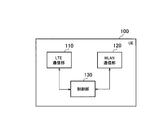
- FIG. 3 is a block diagram of the UE 100 (wireless terminal). As illustrated in FIG. 3, the UE 100 includes an LTE communication unit (WWAN communication unit) 110, a WLAN communication unit 120, and a control unit 130.
- WWAN communication unit LTE communication unit
- WLAN communication unit Wireless Local Area Network
- the LTE communication unit 110 performs LTE communication under the control of the control unit 130.
- the LTE communication unit 110 may execute part of the LTE protocol.
- the LTE communication unit 110 includes an antenna, a transmitter, and a receiver.
- the transmitter converts the baseband signal (transmission signal) output from the control unit 130 into an LTE radio signal and transmits it from the antenna.
- the receiver converts the LTE radio signal received by the antenna into a baseband signal (received signal) and outputs the baseband signal to the control unit 130. Note that LTE communication is generally performed in a license band.
- the WLAN communication unit 120 performs WLAN communication under the control of the control unit 130.
- the WLAN communication unit 120 may execute part of the WLAN protocol.
- the WLAN communication unit 120 includes an antenna, a transmitter, and a receiver.
- the transmitter converts the baseband signal (transmission signal) output from the control unit 130 into a WLAN radio signal and transmits it from the antenna.
- the receiver converts the WLAN radio signal received by the antenna into a baseband signal (received signal) and outputs the baseband signal to the control unit 130. Note that WLAN communication is generally performed in an unlicensed band.
- the control unit 130 performs various controls in the UE 100.
- the control unit 130 may execute part of the LTE protocol or may execute part of the WLAN protocol.
- the control unit 130 includes a processor and a memory.
- the memory stores a program executed by the processor and information used for processing by the processor.
- the processor may include a baseband processor that modulates / demodulates and encodes / decodes a baseband signal, and a CPU (Central Processing Unit) that executes programs stored in the memory and performs various processes. .
- the processor executes various processes described later.
- FIG. 4 is a block diagram of the eNB 200 (base station). As illustrated in FIG. 4, the eNB 200 includes an LTE communication unit (WWAN communication unit) 210, a control unit 230, and a backhaul communication unit 240. However, in the case of the Collated scenario, the eNB 200 may include the WLAN communication unit 220.
- WWAN communication unit LTE communication unit
- control unit 230 control unit
- backhaul communication unit 240 backhaul communication unit 240
- the eNB 200 may include the WLAN communication unit 220.
- the LTE communication unit 210 performs LTE communication under the control of the control unit 230.
- the LTE communication unit 210 may execute part of the LTE protocol.
- the LTE communication unit 210 includes an antenna, a transmitter, and a receiver.
- the transmitter converts the baseband signal (transmission signal) output from the control unit 230 into an LTE radio signal and transmits it from the antenna.
- the receiver converts the LTE radio signal received by the antenna into a baseband signal (received signal) and outputs the baseband signal to the control unit 230.
- the WLAN communication unit 220 performs WLAN communication under the control of the control unit 230.
- the WLAN communication unit 220 may execute part of the WLAN protocol.
- the WLAN communication unit 220 includes an antenna, a transmitter, and a receiver.
- the transmitter converts the baseband signal (transmission signal) output from the control unit 230 into a WLAN radio signal and transmits it from the antenna.
- the receiver converts the WLAN radio signal received by the antenna into a baseband signal (received signal) and outputs the baseband signal to the control unit 230.
- the control unit 230 performs various controls in the eNB 200.
- the control unit 230 may execute part of the LTE protocol or may execute part of the WLAN protocol.
- the control unit 230 includes a processor and a memory.
- the memory stores a program executed by the processor and information used for processing by the processor.
- the processor may include a baseband processor that modulates / demodulates and encodes / decodes a baseband signal, and a CPU (Central Processing Unit) that executes programs stored in the memory and performs various processes. .
- the processor executes various processes described later.
- the backhaul communication unit 240 is connected to the neighboring eNB 200 via the X2 interface, is connected to the EPC 500 (MME / S-GW) via the S1 interface, and is connected to the WT 400 via the Xw interface.
- the backhaul communication unit 240 is used for communication performed on the X2 interface, communication performed on the S1 interface, communication performed on the Xw interface, and the like.
- the communication system performs a network selection operation (Access Network Selection) for selecting a communication target network from among WWAN (E-UTRAN) and WLAN for the data of the UE 100.
- the network selection operation includes a terminal initiative method in which the UE 100 selects a communication target network and a base station initiative method in which the eNB 200 selects a communication target network.
- the terminal initiative method was introduced in Release 12 of the 3GPP standard, it may be referred to as a Release 12 method.
- the base station initiative method is scheduled to be introduced in Release 13 of the 3GPP standard, it may be referred to as the Release 13 method.
- Terminal initiative method In the terminal initiative method, the UE 100 in the RRC connected state or the RRC idle state selects a communication target network from the E-UTRAN and the WLAN, and performs bidirectional communication between the E-UTRAN and the WLAN. Switch (traffic steering). The switching is performed on the basis of UE (UE based) with the assistance of E-UTRAN. The switching is performed in units of APN (Access Point Name).
- APN Access Point Name
- FIG. 5 is a diagram for explaining the terminal initiative method.
- the eNB 200 transmits auxiliary information (RAN assistance parameters) to the UE 100 by broadcast RRC signaling or dedicated RRC signaling.
- the broadcast RRC signaling is, for example, SIB (System Information Block) type 17.
- the dedicated RRC signaling is, for example, an “RRC Connection Reconfiguration” message.
- the auxiliary information includes an E-UTRAN signal strength (received power) threshold value and quality threshold value, a WLAN channel usage rate threshold value, a WLAN backhaul data rate threshold value, a WLAN signal strength (received power) threshold value, a quality threshold value, and the like.
- the auxiliary information may include a WLAN identifier that is a target of the network selection operation.
- the WLAN identifier is SSID (Service Set Identifier), HESSID (Homogenous Extended Service Set Identifier), BSSID (Basic Service Set Identifier), or the like.
- the auxiliary information may include a parameter that specifies a period during which a threshold value (determination condition) should be satisfied.
- the UE 100 receives the auxiliary information and stores the received auxiliary information.
- step S12 the UE 100 performs a network selection operation.
- the UE 100 determines whether to switch from E-UTRAN to WLAN based on the first determination condition regarding E-UTRAN and the second determination condition regarding WLAN. Specifically, when both the first determination condition and the second determination condition are satisfied, the UE 100 performs switching from E-UTRAN to WLAN.
- the first determination condition is the following condition for the E-UTRAN serving cell.
- RSRPmeas is the received power of the LTE reference signal measured by the UE 100, that is, the reference signal received power (RSRP).
- RSSmeas is the reception quality of the LTE reference signal measured by the UE 100, that is, the reference signal reception quality (RSRQ).
- RSRQ reference signal reception quality
- ThreshServingOffloadWLAN, LowP” and “ThreshServingOffloadWLAN, LowQ” are thresholds included in the auxiliary information.
- the second determination condition is the following condition for the target WLAN.
- ChannelUtilizationWLAN ⁇ ThreshChUtilWLAN, Low; and BackhaulRateDlWLAN> ThreshBackhRateDLWLAN, High; and BackhaulRateUlWLAN> ThreshBackhRateULWLAN, High; and BeaconRSSI> ThreshBeaconRSSIWLAN, High;
- ChannelUtilization WLAN is included in the WLAN beacon or probe response and indicates the WLAN channel usage rate, that is, the WLAN wireless load level.
- “BackhaulRateDlWLAN” and “BackhaulRateUlWLAN” are provided by ANQP (Access Network Query Protocol) and indicate the available transmission rate of the WLAN backhaul, that is, the WLAN backhaul load level.
- Beacon RSSI indicates the WLAN signal strength measured by the UE 100. “ThreshChillWLAN, Low”, “ThreshBackRateDLWLAN, High”, “ThreshBackRateULWLAN, High”, and “ThreshBeaconRSSIWLAN, High” are threshold values included in the auxiliary information.
- the UE 100 determines whether to switch from the WLAN to the E-UTRAN based on the third determination condition related to the WLAN and the fourth determination condition related to the E-UTRAN. Specifically, when one of the third determination condition or the fourth determination condition is satisfied, the UE 100 performs switching from WLAN to E-UTRAN.
- the third determination condition is the following condition for the source WLAN.
- the fourth determination condition is the following condition for the E-UTRAN target cell.
- “ThreservingOffloadWLAN, HighP” and “ThreservingOffloadWLAN, HighQ” are thresholds included in the auxiliary information.
- the AS layer (first entity) of UE 100 indicates that the switching condition is satisfied. Entity).
- the upper layer is, for example, a NAS layer (or application layer).
- the eNB 200 selects a communication target network of the UE 100 from E-UTRAN and WLAN based on a measurement report from the UE 100, and switches for switching the communication target network. An instruction is transmitted to UE100.
- ENB200 transmits WLAN measurement setting for setting a WLAN measurement report to UE100.
- the eNB 200 includes the WLAN measurement setting in the “RRC Connection Reconfiguration” message that is dedicated RRC signaling addressed to the UE 100.
- UE100 receives WLAN measurement setting from eNB200.
- the WLAN measurement setting includes a predetermined identifier associated with the WLAN AP group to be measured.
- the predetermined identifier is associated with the identifier of each WLAN AP 300 in the WLAN AP group to be measured.
- the predetermined identifier is a measurement target setting identifier for setting a measurement target.
- a measurement target identifier measObjectId
- the WLAN measurement setting includes an index of each WLAN AP 300 in the WLAN AP group to be measured.
- the index has a shorter bit length than the identifier of WLAN AP300.
- the identifier (WLAN identifier) of the WLAN AP 300 is, for example, SSID, HESSID, or BSSID.
- a signaling overhead can be reduced by introducing an index shorter than the identifier and transmitting / receiving the index. For example, when only a part of the WLAN AP 300 is removed from the measurement target, the removal can be instructed using an index.
- the WLAN measurement setting further includes an identifier of each WLAN AP 300 in the WLAN AP group to be measured.
- FIG. 6 is a sequence diagram showing an operation pattern 1A of the base station initiative method.
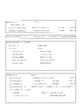
- FIG. 7 is a diagram showing a configuration of WLAN measurement settings.
- FIG. 8 is a diagram illustrating a specific example of WLAN measurement setting in the operation pattern 1A of the base station initiative method. Note that “Need ON” in FIG. 8 indicates that the parameter is optional, and when there is no value corresponding to the parameter, the UE 100 continues to use the currently set value.
- step S101 the eNB 200 transmits the WLAN measurement setting to the UE 100.
- the UE 100 receives the WLAN measurement setting.
- the WLAN measurement setting (MeasConfig) includes a measurement target (MeasObject), a report setting (ReportConfig), and a measurement identifier (MeasID).
- the measurement identifier (MeasID) associates the measurement target (MeasObject) with the report setting (ReportConfig).
- the measurement identifier (MeasID) indicates a combination of an identifier (MeasObjectID) of a measurement target (MeasObject) setting and an identifier (ReportConfigID) of a report setting (ReportConfig). Identifies the combination.
- the measurement target (MeasObject) included in the WLAN measurement settings (MeasConfig) includes a list of measurement targets to be removed (MeasObjectToRemoveList) and a list of measurement targets to be added / changed (MeasObjectToAddModList).
- Each measurement target (MeasObjectToAddMod) included in the list of measurement targets to be added / changed (MeasObjectToAddModList) includes a measurement target identifier (measObjectId) and a measurement target (measObject).
- the measurement target (measObject) includes a measurement target WLAN (MeasObjectWLAN).
- the measurement target WLAN includes the measurement target WLAN frequency (wlancarrierFreq), the list of WLAN APs to be removed from the measurement target (wlanToRemoveList), and the list of WLAN APs to be added / changed to the measurement target (wlanToAddModList).
- FIG. 8 shows an example in which the measurement target WLAN frequency (wlancarrierFreq) is 2.4 GHz or 5 GHz.
- the list of WLAN APs to be removed from the measurement target includes a list of WLAN AP indexes (wlanIndexList).
- Each WLAN AP information (WlanToAddMod) included in the list of WLAN APs to be added / changed to the measurement target (wlanToAddModList) includes an index (wlanIndex) and an identifier (wlan-Identifiers-r13) of each WLAN AP.
- the report setting (ReportConfig) included in the WLAN measurement setting (MeasConfig) includes a trigger type (TriggerType) of the WLAN measurement report.
- TriggerType a trigger type of the WLAN measurement report.
- “event trigger reporting” that transmits a WLAN measurement report when an event occurs is mainly assumed. Examples of such an event include an event that the quality of WLAN is higher than a threshold value and an event that the quality of WLAN is lower than a threshold value.
- the event may be that the quality of LTE is lower than threshold 1 and the quality of WLAN is higher than threshold 2.
- the event may be that the LTE quality is higher than the threshold value 1 and the WLAN quality is lower than the threshold value 2. It may be an event that the quality of the current WLAN is lower than threshold 1 and the quality of other WLANs is higher than threshold 2.
- the eNB 200 wants to know that the UE 100 moves to the coverage of the WLAN AP group B in the situation as shown in FIG.
- the eNB 200 includes the measurement target identifier (measObjectId) and the measurement target (measObject) corresponding to the WLAN AP group B in the list of measurement targets to be added / changed (MeasObjectToAddModList).
- the eNB 200 combines the measurement target identifier (measObjectId) corresponding to the WLAN AP group B with a report setting (ReportConfig) including an event that the quality of the WLAN is higher than the threshold.
- UE100 transmits the WLAN measurement report regarding the said WLAN AP300 to eNB200, when the quality of WLAN AP300 contained in WLAN AP group B becomes higher than a threshold value.
- the UE 100 performs the measurement indicated by the measurement identifier (MeasID) based on the WLAN measurement setting (MeasConfig). Specifically, the UE 100 performs WLAN measurement for the measurement target WLAN (MeasObject WLAN) corresponding to the measurement identifier (MeasID). Examples of measurement parameters in WLAN measurement include “ChannelUtilization WLAN”, “BackhaulRateDlWLAN”, “BackhaulRateUlWLAN”, “BeaconRSSI”, and the like. “ChannelUtilization WLAN” is included in the WLAN beacon or probe response and indicates the WLAN channel usage, ie, the WLAN radio load level.
- BackhaulRateDlWLAN and “BackhaulRateUlWLAN” are provided by ANQP (Access Network Query Protocol) and indicate the available transmission rate of the WLAN backhaul, that is, the WLAN backhaul load level.
- Beacon RSSI indicates the WLAN signal strength measured by the UE 100.
- the type of measurement parameter in WLAN measurement may be specified by a report setting (ReportConfig).
- step S103 the UE 100 determines that the event specified by the report setting (ReportConfig) has occurred based on the WLAN measurement.
- the UE 100 transmits a WLAN measurement report to the eNB 200.
- the eNB 200 receives the WLAN measurement report.
- the WLAN measurement report includes a measurement identifier (MeasID), a WLAN AP identifier (WLAN identifier), a WLAN measurement result, and the like. Since the measurement identifier (MeasID) is associated with the measurement target identifier (measObjectId), the eNB 200 can identify the WLAN AP group based on the measurement identifier (MeasID).
- the WLAN measurement report may include a measurement object identifier (measObjectId).
- the WLAN measurement report may include a WLAN AP index (WLAN index) instead of the WLAN AP identifier (WLAN identifier).
- the eNB 200 grasps that the UE 100 has moved to the coverage of the WLAN AP group to be measured based on the WLAN measurement report. Moreover, eNB200 determines WLAN AP300 which should perform WLAN communication with UE100 among WLAN AP300 contained in the WLAN AP group of a measuring object.
- the eNB 200 transmits to the UE 100 a switching instruction including the determined WLAN AP 300 identifier (WLAN identifier).
- WLAN identifier instead of the WLAN AP identifier (WLAN identifier), a WLAN AP index (WLAN index) may be used.
- the UE 100 receives the switching instruction.
- Such a switching instruction may be referred to as “Steering command”.
- the switching instruction is an instruction for switching WLAN communication from one WLAN AP 300 to another WLAN AP 300.
- the switching instruction may be an instruction for switching the WLAN communication from the WLAN AP 300 belonging to one WLAN AP group to the WLAN AP 300 belonging to another WLAN AP group.
- the switching instruction may be an instruction for switching communication (data) from the eNB 200 to the WLAN AP 300.
- the switching instruction may be an instruction to start “WLAN Aggregation” in which the UE 100 simultaneously performs communication with the eNB 200 and communication with the AP 300.
- the start instruction of “WLAN Aggregation” may be transmitted from the eNB 200 to the UE 100 by the “RRC Connection Reconfiguration” message.
- step S106 the UE 100 switches to the WLAN AP 300 designated by the switching instruction.
- the UE 100 may transmit an affirmative response or negative response to the switching instruction to the eNB 200.
- the eNB 200 transmits notification information different from the WLAN measurement setting to the UE 100 by broadcast or unicast.
- the notification information includes an index and an identifier of each of the plurality of WLAN APs 300.
- UE100 receives notification information.
- UE100 may receive notification information from EPC500 (core network) via eNB200.
- the UE 100 receives notification information from an ANDSF (Access Network Discovery and Selection Function) provided in the EPC 500.
- ANDSF Access Network Discovery and Selection Function
- the correspondence between the index and identifier of each WLAN AP 300 is notified to the UE 100 separately from the WLAN measurement setting.
- the identifier of the WLAN AP 300 in the WLAN measurement setting, and the index of the WLAN AP 300 may be included in the WLAN measurement setting. Therefore, the size of the WLAN measurement setting (specifically, MeasObjectWLAN) can be reduced.
- the WLAN measurement setting specifically, MeasObject WLAN
- the effect of reducing signaling overhead is great.
- FIG. 9 is a sequence diagram showing an operation pattern 1B of the base station initiative method. Here, differences from the operation pattern 1A of the base station initiative method are mainly described.
- step S131 the eNB 200 transmits notification information including the indexes and identifiers of a plurality of WLAN APs 300 existing in its own coverage to the UE 100 by broadcast or unicast.
- the UE 100 receives the notification information and stores the received notification information.
- the eNB 200 includes notification information in, for example, an SIB (System Information Block).
- SIB System Information Block
- the eNB 200 includes notification information in a “RRC Connection Reconfiguration” message that is dedicated RRC signaling addressed to the UE 100.
- the eNB 200 transmits the WLAN measurement setting to the UE 100.
- the UE 100 receives the WLAN measurement setting.
- the WLAN measurement setting (specifically, MeasObjectWLAN) includes the index of the WLAN AP 300, but does not include the identifier of the WLAN AP 300. Other points are the same as the WLAN measurement setting in the operation pattern 1A.
- the UE 100 Based on the stored notification information, the UE 100 derives a WLAN identifier corresponding to the index of the WLAN AP 300 included in the WLAN measurement setting.
- step S133 to S137 is the same as the operation pattern 1A of the base station initiative method.
- the predetermined identifier associated with the measurement target WLAN AP group is a group identifier of the measurement target WLAN AP group.
- the WLAN measurement setting further includes an identifier of each WLAN AP 300 in the WLAN AP group to be measured.
- FIG. 10 is a sequence diagram showing an operation pattern 2A of the base station initiative method. Here, differences from the operation pattern 1A of the base station initiative method are mainly described.
- step S151 the eNB 200 transmits the WLAN measurement setting to the UE 100.
- the UE 100 receives the WLAN measurement setting.
- the measurement target (MeasObject) included in the WLAN measurement setting (MeasConfig) includes a list of measurement targets to be removed (MeasObjectToRemoveList) and a list of measurement targets to be added / changed (MeasObjectToAddModList). .
- Each measurement target (MeasObjectToAddMod) included in the list of measurement targets to be added / changed (MeasObjectToAddModList) includes a measurement target identifier (measObjectId) and a measurement target (measObject).
- the measurement target (measObject) includes a measurement target WLAN (MeasObjectWLAN).
- the measurement target WLAN (MeasObjectWLAN) includes a group identifier.
- the measurement target WLAN includes the measurement target WLAN frequency (wlancarrierFreq), the list of WLAN APs to be removed from the measurement target (wlanToRemoveList), and the list of WLAN APs to be added / changed to the measurement target (wlanToAddModList).
- the list of WLAN APs to be removed from the measurement target includes a list of WLAN AP identifiers (WLAN identifiers).
- Each WLAN AP information (WlanToAddMod) included in wlanToAddModList includes an identifier (wlan-Identifiers-r13) of each WLAN AP.
- step S152 the UE 100 performs the measurement indicated by the measurement identifier (MeasID) based on the WLAN measurement setting (MeasConfig). Specifically, the UE 100 performs WLAN measurement for the measurement target WLAN (MeasObject WLAN) corresponding to the measurement identifier (MeasID).
- step S153 the UE 100 determines that the event specified by the report setting (ReportConfig) has occurred based on the WLAN measurement.
- the UE 100 transmits a WLAN measurement report to the eNB 200.
- the eNB 200 receives the WLAN measurement report.
- the WLAN measurement report includes a group identifier, a WLAN AP identifier (WLAN identifier), a WLAN measurement result, and the like.
- the eNB 200 can identify the WLAN AP group based on the group identifier.
- the WLAN measurement report includes a WLAN AP identifier (WLAN identifier), but may not include a group identifier. This is because if the eNB 200 can uniquely identify the WLAN AP group by receiving the WLAN identifier, the group identifier may be unnecessary.
- the WLAN measurement report may include a group identifier but not a WLAN identifier. This is because when the UE 100 initially connects to the WLAN, the WLAN identifier may not be required.
- the eNB 200 grasps that the UE 100 has moved to the coverage of the WLAN AP group to be measured based on the WLAN measurement report. Moreover, eNB200 determines WLAN AP300 which should perform WLAN communication with UE100 among WLAN AP300 contained in the WLAN AP group of a measuring object.
- the eNB 200 transmits a switching instruction including the determined identifier (WLAN identifier) of the WLAN AP 300 to the UE 100.
- the UE 100 receives the switching instruction.
- the switching instruction may include a group identifier instead of the WLAN AP identifier (WLAN identifier).
- WLAN identifier the WLAN AP identifier
- step S156 the UE 100 performs switching to the WLAN AP 300 (or the designated WLAN AP group) designated by the switching instruction.
- the switching instruction may be an instruction to start “WLAN Aggregation” in which the UE 100 simultaneously performs communication with the eNB 200 and communication with the AP 300.
- the UE 100 may transmit an affirmative response or negative response to the switching instruction to the eNB 200.
- the eNB 200 transmits notification information different from the WLAN measurement setting to the UE 100 by broadcast or unicast.
- the notification information includes the group identifier of the WLAN AP group and the identifier of each WLAN AP 300 in the WLAN AP group.
- UE100 receives notification information.
- UE100 may receive notification information from EPC500 (core network) via eNB200.
- the UE 100 receives notification information from an ANDSF provided in the EPC 500.
- the UE 100 is notified of the correspondence between the group identifier of the WLAN AP group and the identifier of each WLAN AP 300 in the WLAN AP group separately from the WLAN measurement setting.
- the identifier of the WLAN AP 300 in the WLAN measurement setting
- the group identifier of the WLAN AP group to be measured may be included in the WLAN measurement setting. Therefore, the size of the WLAN measurement setting (specifically, MeasObjectWLAN) can be reduced.
- the WLAN measurement setting specifically, MeasObject WLAN
- the effect of reducing signaling overhead is great.
- FIG. 11 is a sequence diagram showing an operation pattern 2B of the base station initiative method. Here, differences from the operation pattern 2A of the base station initiative method will be mainly described.
- step S171 the eNB 200 broadcasts or unicasts notification information including the group identifier of the WLAN AP group existing in its own coverage and the identifier of each WLAN AP 300 in the WLAN AP group to the UE 100. To do.
- the UE 100 receives the notification information and stores the received notification information.
- the eNB 200 includes notification information in, for example, an SIB (System Information Block).
- SIB System Information Block
- the eNB 200 includes notification information in a “RRC Connection Reconfiguration” message that is dedicated RRC signaling addressed to the UE 100.
- the eNB 200 transmits the WLAN measurement setting to the UE 100.
- the UE 100 receives the WLAN measurement setting.
- the WLAN measurement setting (specifically, MeasObjectWLAN) includes the group identifier of the WLAN AP group to be measured, but does not include the identifier of the WLAN AP 300.
- the other points are the same as the WLAN measurement setting in the operation pattern 2A.
- the UE 100 derives each WLAN identifier corresponding to the group identifier included in the WLAN measurement configuration based on the stored notification information.
- step S173 to S177 is the same as the operation pattern 2A of the base station initiative method.
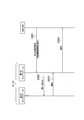
- FIG. 12 is a sequence diagram illustrating an operation of the UE 100 that has received the switching instruction.
- the UE 100 includes a first entity 131 that performs WWAN communication with the eNB 200, and a second entity 132 that is positioned in a higher layer than the first entity 131.
- the first entity 131 and the second entity 132 are included in the control unit 130 of the UE 100.
- the first entity 131 is an AS layer entity.
- the first entity 131 may be an RRC layer entity among AS layer entities.
- the second entity 132 is a NAS layer entity.
- the second entity 132 may be an application layer entity.
- the first entity 131 receives a switching instruction for switching the communication target network between WWAN (E-UTRAN) and WLAN for the data of the UE 100 from the eNB 200.
- the switching instruction is transmitted from the eNB 200 by dedicated RRC signaling addressed to the UE 100 (for example, an “RRC Connection Reconfiguration” message).
- RRC Connection Reconfiguration an instruction to switch (offload) from E-UTRAN to WLAN.
- the switching instruction includes an identifier related to the connection target WLAN.
- the identifier related to the WLAN to be connected is at least one of an identifier of the WLAN AP 300 (WLAN identifier), an index of the WLAN AP 300 (WLAN index), and an identifier of the WLAN AP group (group identifier).
- the switching instruction may include a bearer identifier to be switched (offload target).
- the bearer identifier is at least one of an EPS (Evolved Packet System) bearer ID, a DRB (Data Radio Bearer) ID, and an E-RAB ID.
- the switching instruction may include information on an APN that is a switching target (offload target).
- step S192 the first entity 131 notifies the second entity 132 of an indicator (move-traffic-to-WLAN) indicating switching of the communication target network in response to receiving the switching instruction from the eNB 200.
- a terminal initiative method in which the first entity 131 performs network selection for selecting a communication target network from WWAN and WLAN, and a base station initiative method in which the eNB 200 performs the network selection are defined.
- the first entity 131 notifies the second entity 132 of an indicator that can identify that the base station initiative method is applied.
- the indicator that can identify that the base station initiative method is applied is a dedicated indicator for the base station initiative method.
- the indicator is move-traffic-to-WLAN-r13.
- the indicator that can identify that the base station initiative method is applied is obtained by adding information indicating the base station initiative method to the indicator in the terminal initiative method.
- the first entity 131 adds “Preference Indicator” to the release 12 move-traffic-to-WLAN (indicator in the terminal initiative method).
- the “Preference Reference Indicator” is, for example, a special OPI (Offload Prefence Indicator).
- the second entity 132 appropriately determines whether or not to switch the communication target network. Can be done. Specifically, when switching of the communication target network is instructed by the base station initiative method, it is determined that it is highly necessary to switch the communication target network, and processing for switching the communication target network can be performed.
- the switching instruction instructs switching from the WWAN to the WLAN
- the switching instruction includes an identifier related to the connection target WLAN.
- the first entity 131 notifies the second entity 132 of the indicator
- the first entity 131 notifies the second entity 132 of the identifier related to the connection target WLAN included in the switching instruction.
- the first entity 131 may notify the second entity 132 of the bearer identifier included in the switching instruction.
- the first entity 131 may notify the second entity 132 of the APN information included in the switching instruction.
- the second entity 132 determines whether or not to switch the communication target network from WWAN to WLAN in response to receiving the indicator from the first entity 131.
- the second entity 132 performs processing for switching the communication target network from WWAN to WLAN by connecting to the connection target WLAN based on the identifier related to the connection target WLAN.
- the communication target network is switched in units of APN.
- the second entity 132 may switch the communication target network only for the bearer indicated by the bearer identifier.
- the second entity 132 notifies the first entity 131 of the response.
- the response may include at least one bearer identifier that has undergone switching (offload) (or has decided to do so).
- the response may include at least one bearer identifier that cannot be switched (offloaded) instead of or in addition to such a bearer identifier.
- step S194 the first entity 131 notifies the eNB 200 of the response based on the response from the second entity 132.
- the first entity 131 transmits a report (WLAN connection complete report) indicating the connection to the WLAN to the eNB 200.
- the first entity 131 transmits information (Cause value) indicating the reason why the switching instruction is not followed to the eNB 200.
- “Cause value” include “notOffloadable PDN connection”, “upperLayerDecision”, “ANDSFFunction”, and the like.
- notOffloadable PDN connection is used when switching cannot be performed because the PDN (Packet Data Network) connection is not allowed to be offloaded.
- PDN connection (PDN connection) is substantially synonymous with APN.
- the “upperLayerDecision” is used when the second entity 132 cannot be switched due to an arbitrary determination.
- “ANDSFFunction” is used when the judgment of ANDSF and the content of the switching instruction do not match.
- the first entity 131 sets the identifier related to the connected WLAN. You may transmit to eNB200.
- the identifier related to the connected WLAN is at least one of a WLAN identifier, a WLAN index, and a group identifier.
- the first entity 131 may transmit the identifier of the bearer that performs switching and the identifier of the bearer that does not perform switching to the eNB 200.
- step S194 is not limited to a response to the instruction in step S191 (for example, an “RRC Connection Reconfiguration Complete” message).
- the message in step S194 may be a message (for example, “UE Assistance Information” message) that the UE 100 voluntarily transmits.
- the eNB 200 performs network selection for selecting the communication target network from among WWAN (E-UTRAN) and WLAN for the data of the UE 100, and sets the communication target network as the WWAN and the WLAN based on the result of the network selection.
- indication for switching between is transmitted to UE100.
- eNB200 performs network selection based on the predetermined information acquired from the specific apparatus different from UE100. Specifically, the eNB 200 determines whether to switch to the WLAN based on the predetermined information.
- the specific device is a core network device provided in the WWAN core network (EPC 500).
- the predetermined information is bearer information indicating whether the data of the UE 100 is data belonging to a bearer that can be switched from WWAN to WLAN.
- the eNB 200 acquires bearer information from the core network device when a bearer is established or a bearer is changed.
- the specific device is a WLAN device provided in the WLAN.
- the predetermined information is at least one of position information related to the WLAN AP, load information related to the WLAN AP, and performance information related to the WLAN AP.
- FIG. 13 is a sequence diagram illustrating an example of an operation pattern 1 according to the second embodiment.
- the core network device is a mobility management device (MME: Mobility Management Entity) 510
- MME Mobility Management Entity
- the MME 510 transmits a bearer establishment request (E-RAB SETUP REQUEST) for establishing a bearer (E-RAB: E-UTRAN Radio Access Bearer) to the eNB 200.
- E-RAB is a bearer established between the UE 100 and an S-GW (Serving Gateway).
- the E-RAB includes a data radio bearer (DRB) between the UE 100 and the eNB 200 and an S1 bearer between the eNB 200 and the S-GW.
- An EPS bearer is configured by the E-RAB and the S5 / S8 bearer.
- the S5 / S8 bearer is a bearer between the S-GW and the P-GW (PDN Gateway).
- the bearer establishment request includes a list of E-RABs to be established (E-RAB To Be Setup List).
- the MME 510 includes a flag indicating whether switching to WLAN is possible for each E-RAB in a bearer establishment request (E-RAB SETUP REQUEST). For example, the MME 510 sets “1” as an E-RAB flag that can be switched to a WLAN, and sets “0” as an E-RAB flag that cannot be switched to a WLAN.
- the eNB 200 stores information included in the bearer establishment request (E-RAB SETUP REQUEST).
- the MME 510 knows the correspondence between the EPS bearer, the PDN connection (APN), and the E-RAB, and therefore knows the correspondence between the E-RAB and the APN. Also, the MME 510 grasps the information of the APN that can be switched (offloaded) to the WLAN based on whether or not the P-GW has a connection capability with the network on the WLAN side and the restriction information for each APN. Yes. Or MME510 may acquire the information regarding APN which can be switched to WLAN from PCRF (Policy and Charging Rules Function).
- PCRF Policy and Charging Rules Function
- step S202 the eNB 200 establishes the data radio bearer and the S1 bearer in response to receiving the bearer establishment request (E-RAB SETUP REQUEST).
- step S203 the eNB 200 transmits a bearer establishment response (E-RAB SETUP RESPONSE) to the MME 510.
- E-RAB SETUP RESPONSE a bearer establishment response
- ENB200 performs the network selection of the base station initiative system mentioned above. Since the eNB 200 knows whether or not the E-RAB of the UE 100 is an E-RAB that can be switched to the WLAN, the eNB 200 can appropriately transmit a switching instruction to the WLAN (Steering command) to the UE 100. Specifically, the eNB 200 confirms whether or not the E-RAB of the UE 100 can be switched to the WLAN, and transmits an instruction to switch to the WLAN 100 only when switching to the WLAN is possible. In addition, when the UE 100 has only one PDN connection (APN) and an E-RAB that cannot be offloaded is associated with the PDN connection, the eNB 200 instructs to switch to the WLAN. Is not transmitted to UE100. Thereby, transmission of an inappropriate switching instruction can be avoided. Alternatively, the eNB 200 may perform control not to transmit the WLAN measurement setting to the UE 100 in place of the control not to transmit the instruction to switch to the WLAN to the UE 100.
- APN PDN connection
- FIG. 13 shows a sequence when a bearer is established, but it may be a sequence when a bearer is changed.
- FIG. 14 is a sequence diagram illustrating another example of the operation pattern 1 according to the second embodiment. Here, differences from FIG. 13 will be mainly described.
- the MME 510 transmits a bearer change request (E-RAB MODIFY REQUEST) for changing a bearer (E-RAB: E-UTRAN Radio Access Bearer) to the eNB 200.
- the bearer change request (E-RAB MODIFY REQUEST) includes a list of E-RABs to be changed (E-RAB To Be Modified List).
- the MME 510 includes a flag indicating whether switching to WLAN is possible in the bearer change request (E-RAB MODIFY REQUEST) for each E-RAB.
- the eNB 200 stores information included in the bearer establishment request (E-RAB SETUP REQUEST).
- step S212 the eNB 200 changes the data radio bearer and the S1 bearer in response to receiving the bearer change request (E-RAB MODIFY REQUEST).
- step S213 the eNB 200 transmits a bearer change response (E-RAB MODIFY RESPONSE) to the MME 510.
- E-RAB MODIFY RESPONSE a bearer change response
- the eNB 200 may determine whether to instruct the UE 100 to switch to the WLAN in consideration of the transmission / reception data amount for each bearer. Realizing more efficient offload by considering whether it is an E-RAB associated with an offloadable PDN connection or not, and whether it is a bearer worthy of indicating an offload Is expected.
- FIG. 15 is a sequence diagram illustrating an example of an operation pattern 2 according to the second embodiment.
- the WLAN device is the WT 400.
- the eNB 200 requests the WT 400 to transmit WLAN information.
- the WLAN information is information related to the WLAN AP 300 that the WT 400 accommodates.
- the WLAN information may be information for each WLAN AP 300 or information for each WLAN AP group.
- the WLAN information is at least one of position information related to the WLAN AP 300, load information related to the WLAN AP 300, and performance information related to the WLAN AP 300.
- the location information related to the WLAN AP 300 is information indicating the geographical location of the WLAN AP 300 or a group thereof.
- the load information related to the WLAN AP 300 is information indicating the load level (for example, the number of connected UEs) of the WLAN AP 300 or a group thereof.
- the performance information related to the WLAN AP 300 is information indicating the performance of the WLAN AP 300 or its group (for example, which series of IEEE 802.11). Note that step S221 is not essential and may be omitted.
- step S222 the WT 400 transmits the WLAN information to the eNB 200.
- the eNB 200 receives the WLAN information and stores the received WLAN information.
- ENB200 performs the network selection of the base station initiative system mentioned above. Since the eNB 200 knows the information of the WLAN AP 300 to be switched or the group thereof, the eNB 200 can appropriately transmit a switching instruction to the WLAN to the UE 100.
- the eNB 200 grasps the position of the WLAN AP 300 or the group indicated by the WLAN measurement report based on the WLAN measurement report from the UE 100 and the position information related to the WLAN AP 300.
- the eNB 200 instructs the UE 100 to switch to the WLAN AP 300 or the group.
- the terminal-driven network selection has a characteristic that the UE 100 located in the cell edge region easily selects the WLAN, and the UE 100 located in the cell center region hardly selects the WLAN. Therefore, when the combined use of the terminal initiative method and the base station initiative method is assumed, it is preferable to apply the base station initiative method only to the UE 100 located in the cell center region.
- the eNB 200 grasps the load level of the WLAN AP 300 or the group indicated by the WLAN measurement report based on the WLAN measurement report from the UE 100 and the load information related to the WLAN AP 300.
- the eNB 200 instructs the UE 100 to switch to the WLAN AP 300 or the group.
- the eNB 200 grasps the performance of the WLAN AP 300 or the group indicated by the WLAN measurement report based on the WLAN measurement report from the UE 100 and the performance information related to the WLAN AP 300.
- the eNB 200 instructs the UE 100 to switch to the WLAN AP 300 or the group.
- the MME 510 may instruct the eNB 200 to release the bearer by a bearer release instruction (E-RAB RELEASE COMMAND).
- E-RAB RELEASE COMMAND a bearer release instruction
- the MME 510 communicates with the second entity 132 of the UE 100, grasps the switching to the WLAN, and transmits a bearer release instruction (E-RAB RELEASE COMMAND) to the eNB 200.
- step S194 in FIG. 12 may be unnecessary.
- the bearer release instruction (E-RAB RELEASE COMMAND) includes a list of bearers to be released (E-RAB To Be Released List IE). Since the IE includes Cause, the MME 510 sets “Steering to WLAN” as the Cause.
- the eNB 200 transmits a bearer release response (E-RAB RELEASE RESPONSE) to the MME 510 as a response to the bearer release instruction (E-RAB RELEASE COMMAND).
- MME 510 transmits a bearer establishment request (E-RAB SETUP REQUEST) or a bearer change request (E-RAB MODIFY REQUEST) to eNB 200.
- the MME 510 sets “Stealing from WLAN” as Cause in the list of bearers included in the bearer establishment request (E-RAB SETUP REQUEST) or the bearer change request (E-RAB MODIFY REQUEST).
- the eNB 200 acquires information on bearers that are switched between the WWAN and the WLAN from the MME 510.
- the UE 100 starts the WLAN measurement based on the WLAN measurement setting from the eNB 200 and transmits the WLAN measurement report to the eNB 200 when the report condition is satisfied.
- the WLAN measurement report is used for “WLAN / 3GPP interworking enhancement” in addition to “WLAN / 3GPP interworking enhancement”.
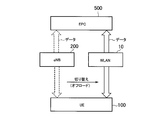
- FIG. 16 is a diagram for explaining “WLAN / 3GPP interworking enhancement”.
- the eNB 200 transmits a switching instruction (Steering Command) to the UE 100 based on the WLAN measurement report from the UE 100.
- UE100 switches the network used for the data communication of UE100 from WWAN (eNB200) to WLAN10 according to reception of the switching instruction
- Such data switching is referred to as “offload”.
- FIG. 17 is a diagram for explaining “LTE-WLAN aggregation”.
- LTE-WLAN aggregation in the downlink will be described, but “LTE-WLAN aggregation” can also be applied to the uplink.
- the eNB 200 transmits a “RRC Connection Reconfiguration” message to the UE 100 based on the WLAN measurement report from the UE 100 to instruct the start of “LTE-WLAN aggregation”.
- the UE 100 starts “LTE-WLAN aggregation” in response to reception of the switching instruction (Steering Command).
- the UE 100 uses communication with the WWAN (eNB 200) and communication with the WLAN 10 at the same time.
- the data of bearer # 1 of the UE 100 is transmitted from the eNB 200 to the UE 100.
- at least a part of the data of bearer # 2 of the UE 100 is transmitted from the eNB 200 to the UE 100 via the WLAN 10.
- the eNB 200 includes a PDCP layer entity (PDCP entity) # 1 corresponding to the bearer # 1 and a PDCP entity # 2 corresponding to the bearer # 2.
- PDCP entity # 1 processes bearer # 1 data (PDCP SDU) transferred on the S1 interface from S-GW, and processes the processed data (PDCP PDU) to RLC layer entity (RLC entity) # 1 hand over.
- the RLC entity # 1 processes the data from the PDCP entity # 1 as an RLC SDU, and delivers the processed data (RLC PDU) to the LTE MAC layer entity (LTE MAC entity).
- LTE MAC entity processes the data from the RLC entity # 1 as a MAC SDU, and transmits the processed data (MAC PDU) to the UE 100 via a physical layer entity (not shown).
- the PDCP entity # 2 processes the bearer # 2 data (PDCP SDU) transferred from the S-GW on the S1 interface, and transfers at least a part of the processed data (PDCP PDU) to the WLAN 10 on the Xw interface. To do. On the Xw interface, the data of the UE 100 may be transferred using GTP-U (GPRS Tunneling Protocol for User plane). IP tunneling may be used instead of GTP-U.
- GTP-U GPRS Tunneling Protocol for User plane
- IP tunneling may be used instead of GTP-U.
- the remaining PDCP PDUs are delivered to the RLC entity # 2, and are transmitted to the UE 100 through the same processing as the bearer # 1.
- the WLAN 10 includes a WLAN logical link control (LLC: Logical Link Control) layer entity (WLAN LLC entity) and a WLAN medium access control (MAC) layer entity (WLAN MAC entity).
- LLC entity processes the bearer # 2 data (PDCP PDU) transferred from the eNB 200 and delivers the processed data to the WLAN MAC entity.
- PDCP PDU bearer # 2 data
- the WWAN MAC entity processes data from the WLAN LLC entity, and transmits the processed data to the UE 100 via a physical layer entity (not shown).
- an aggregation layer entity defined by the 3GPP standard may be provided instead of the WLAN LLC entity shown in FIG. 17, an aggregation layer entity defined by the 3GPP standard may be provided.
- the bearer # 2 data (PDCP PDU) transferred from the eNB 200 may be directly delivered to the WLAN MAC entity without providing either the WLAN LLC entity or the aggregation layer entity.
- the eNB 200 when the eNB 200 according to the third embodiment transmits a WLAN measurement setting (MeasConfig) for setting the WLAN measurement report to the UE 100, information on the use of the WLAN measurement report (hereinafter referred to as “use-related information”).
- use-related information information on the use of the WLAN measurement report (hereinafter referred to as “use-related information”).
- use-related information include “WLAN / 3GPP interworking enhancement” (specific use), “LTE-WLAN aggregation”, and other uses.
- Other applications include, for example, MRO (Mobility Robustness Optimization).
- Use-related information is, for example, “00” for “WLAN / 3GPP interworking enhancement”, “01” for “LTE-WLAN aggregation”, and “10” for other uses. It may be information that directly indicates the purpose of use. In addition, the usage related information may be defined as information indicating a cause of the WLAN measurement setting. Note that the usage-related information is preferably added in the SEQUENCE of the MeasObject WLAN (see the bottom frame in FIG. 8). This is because it is considered that only the WLAN measurement needs to be specified.
- the usage-related information may be information that indirectly indicates the usage of the WLAN measurement report, such as an event type included in the report configuration (ReportConfig) during the WLAN measurement configuration.
- an event type such as “Event WI” is used for “WLAN / 3GPP interworking enhancement”, and “Event WA” is used for “LTE-WLAN aggregation”.
- the UE 100 includes the first entity 131 that performs communication with the eNB 200, and the second entity 132 that is positioned in a higher layer than the first entity 131.
- the first entity 131 is an AS layer entity.
- the first entity 131 may be an RRC layer entity among AS layer entities.
- the second entity 132 is a NAS layer entity.
- the second entity 132 may be an application layer entity.
- the first entity 131 receives a WLAN measurement setting including usage-related information from the eNB 200.
- the usage-related information indicates “WLAN / 3GPP interworking enhancement” (specific usage)
- the first entity 131 inquires the second entity 132 about the presence / absence of data that can be switched from the WWAN to the WLAN.
- the first entity 131 may notify the eNB 200 of the result of the inquiry with respect to the second entity 132.
- the first entity 131 indicates that the usage related information indicates “WLAN / 3GPP interworking enhancement”, and the measurement result for the WLAN satisfies the transmission condition (report condition) of the WLAN measurement report.
- the second entity 132 is inquired about the presence or absence of data that can be switched from WWAN to WLAN. Then, when the result of the inquiry to the second entity 132 indicates that there is data that can be switched from WWAN to WLAN, the first entity 131 transmits a WLAN measurement report to the eNB 200. On the other hand, when the result of the inquiry to the second entity 132 indicates that there is no data that can be switched from WWAN to WLAN, the first entity 131 stops transmitting the WLAN measurement report.
- FIG. 18 is a sequence diagram showing an operation pattern 1 of the third embodiment. Here, it is assumed that the usage related information indicates “WLAN / 3GPP interworking enhancement”.
- the eNB 200 transmits the WLAN measurement setting to the UE 100.
- the eNB 200 may transmit the WLAN measurement setting to the UE 100 by an “RRC Connection Reconfiguration” message that is a type of RRC signaling.
- the WLAN measurement settings include application related information.
- the first entity 131 of the UE 100 receives the WLAN measurement configuration including usage related information.
- step S302 the first entity 131 inquires of the second entity 132 whether there is data that can be offloaded.
- step S303 the second entity 132 notifies the first entity 131 of the inquiry result.
- the operation of the first entity 131 notified from the second entity 132 that there is data that can be offloaded will be described.
- the first entity 131 notifies the eNB 200 that there is data that can be offloaded, for example, by RRC signaling.
- the RRC signaling may be a completion response (RRC Connection Reconfiguration Complete) message to the “RRC Connection Reconfiguration” message, or may be another message.
- the operation of the first entity 131 notified from the second entity 132 that there is no data that can be offloaded will be described.
- the first entity 131 notifies the eNB 200 that there is no data that can be offloaded, for example, by RRC signaling.
- the RRC signaling may be a completion response (RRC Connection Reconfiguration Complete) message to the “RRC Connection Reconfiguration” message, or may be another message.
- the eNB 200 may newly transmit a “RRC Connection Reconfiguration” message to the UE 100.
- the UE 100 and the eNB 200 may ignore the WLAN measurement setting at least during a situation where there is no data that can be offloaded.
- FIG. 19 is a sequence diagram showing an operation pattern 2 of the third embodiment.
- the operation pattern 2 is an operation pattern in consideration of the possibility that the state of the presence / absence of offloadable data changes after the WLAN measurement setting in the operation pattern 1.
- the usage related information indicates “WLAN / 3GPP interworking enhancement”.
- step S ⁇ b> 311 the eNB 200 transmits a WLAN measurement setting to the UE 100.
- the eNB 200 may transmit the WLAN measurement setting to the UE 100 by an “RRC Connection Reconfiguration” message that is a type of RRC signaling.
- the WLAN measurement settings include application related information.
- the first entity 131 of the UE 100 receives the WLAN measurement configuration including usage related information.
- step S312 the first entity 131 performs WLAN measurement based on the WLAN measurement setting.
- the first entity 131 detects that the WLAN measurement result satisfies the report condition.
- the reporting condition is, for example, a condition that the WLAN signal strength is higher than a threshold value.
- step S314 the first entity 131 inquires of the second entity 132 whether there is data that can be offloaded.
- step S315 the second entity 132 notifies the first entity 131 of the inquiry result.
- the first entity 131 When the first entity 131 is notified from the second entity 132 that there is data that can be offloaded (step S316: YES), the first entity 131 transmits a WLAN measurement report to the eNB 200 in step S317.
- the first entity 131 stops transmitting the WLAN measurement report.
- the first entity 131 may notify the eNB 200 only once that there is no data that can be offloaded.
- the 1st entity 131 inquires the 2nd entity 132 about the preference information of the user of self-UE100 based on the use relevant information contained in WLAN measurement setting.
- the preference information includes at least one of ON / OFF setting of the WLAN communication function of the own UE 100 and the user's interest in a specific use of the WLAN measurement report. For example, when the usage-related information indicates “WLAN / 3GPP interworking enhancement”, the first entity 131 determines whether the user is interested in performing the “WLAN / 3GPP interworking enhancement”.
- the WLAN measurement setting includes application-related information.
- the WLAN measurement settings may not include application related information.
- the UE 100 may apply the operation according to the third embodiment not only to the “WLAN / 3GPP interworking enhancement” case, but also to the “LTE-WLAN aggregation” case.
- the UE100 performs control not to transmit a WLAN measurement report to the WWAN (eNB 200) when the WLAN communication unit 120 is in the occupied state. Specifically, when the WLAN measurement setting has been set and the WLAN communication unit 120 of the UE 100 is occupied even if the WLAN measurement report trigger condition is satisfied, the UE 100 reports the WLAN measurement report. You do not have to send it. Note that the WLAN communication unit 120 may be referred to as a “WLAN modem”.
- the occupied state indicates a state in which the WLAN communication unit 120 cannot be used for RCLWI and / or LWA.
- the occupied state indicates a state where a WLAN communication function that can be provided to the RCLWI and / or LWA cannot be prepared.
- the state in which the UE 100 is already connected to the specific WLAN by the user's manual operation corresponds to the occupied state.
- a specific WLAN is a WLAN (eg, home WLAN) that is not an operator-controlled WLAN that can be used for RCLWI and / or LWA.
- the UE 100 When the WLAN communication unit 120 is in the occupied state, the UE 100 cannot follow the switching instruction. When such a UE 100 receives a switching instruction, an unexpected error may occur. On the other hand, the eNB 200 transmits a switching instruction to the UE 100 based on the WLAN measurement report. Therefore, when the WLAN communication unit is in the occupied state, the occurrence of an unexpected error can be prevented by not transmitting the WLAN measurement report to the eNB 200 (that is, canceling the transmission of the WLAN measurement report).
- the UE 100 may transmit an indication indicating that the WLAN communication unit 120 is in the occupied state to the eNB 200.
- the UE 100 may start control not to transmit the WLAN measurement report with the transmission of the indication as a trigger.
- the eNB 200 recognizes that the WLAN measurement report is not performed based on the indication.
- the control that does not transmit the WLAN measurement report may be a control that does not apply the WLAN measurement setting.
- the UE 100 may maintain the WLAN measurement setting without discarding it even if it transmits an indication to the eNB 200 that the WLAN communication unit 120 is in the occupied state. Thereafter, the UE 100 may resume (resume) application of the WLAN measurement settings when the WLAN communication unit 120 transitions to an unoccupied state (a state in which the WLAN communication unit 120 can be used for RCLWI and / or LWA). .
- the control not to transmit the WLAN measurement report may be to discard the WLAN measurement setting.
- the UE 100 discards the WLAN measurement setting in response to transmitting an indication indicating that the WLAN communication unit 120 is in the occupied state to the eNB 200.
- the eNB 200 may recognize that the WLAN measurement setting has been discarded in response to reception of the indication.
- the WLAN measurement setting includes information that specifies the state of the WLAN communication unit 120 as a condition for transmitting the WLAN measurement report.
- the condition for transmitting the WLAN measurement report may be included in the report setting (ReportConfig) during the WLAN measurement setting.
- ReportConfig the report setting
- the WLAN communication unit 120 is in an unoccupied state.
- the non-occupied state indicates a state in which the WLAN communication unit 120 can be used for RCLWI and / or LWA.
- an event that the WLAN state becomes better than the threshold is assumed as a condition (Event trigger condition) for transmitting the WLAN measurement report.
- a condition for transmitting the WLAN measurement report.
- the WLAN state may be a WLAN measurement result or may be an offset given to the WLAN measurement result.
- a condition for transmitting the WLAN measurement report a condition such as “the WLAN state is better than the threshold and the WLAN communication unit 120 is in an unoccupied state” is set.
- the UE 100 determines whether to transmit a WLAN measurement report according to the following conditional expression.
- Ms indicates a WLAN measurement result
- Hys indicates an offset value (hysteresis value)
- Thresh indicates a threshold (may be set from the eNB 200).
- EnteringEntercondition indicates a condition for starting or restarting the process of transmitting the WLAN measurement report
- leaving condition indicates a condition of stopping the process of transmitting the WLAN measurement report.
- the UE 100 has exemplified the operation of notifying the WWAN (eNB 200) of the identifier indicating the WLAN to which the own UE has been connected.
- UE100 illustrated operation movement which notifies the notification which shows that self-UE has the data which can be switched from WWAN to WLAN to WWAN.
- the fourth embodiment is an embodiment that focuses on such notification.
- the fourth embodiment can be implemented in combination with the above-described embodiments.
- RALWI RAN Assisted LTE WLAN Interworking
- RCLWI Radio Controlled LTE WLAN LTE, WLAN Interworking
- LWA The aggregation is referred to as “LWA”.
- RALWI is a Release 12 system
- RCLWI and LWA are Release 13 systems.
- FIG. 20 is a diagram illustrating an assumed scenario according to the fourth embodiment.
- RCLWI may be read as LWA.
- the eNB 200 transmits auxiliary information (RAN assistance parameters) for RALWI using the SIB 17.
- the eNB 200 determines to apply RCLWI at time t1.
- the eNB 200 transmits an RCLWI switching instruction (steering command) to the UE 100 at time t2.
- the UE 100 operates according to the RALWI until the switching instruction is received.
- the UE 100 operates according to the RCLWI.
- the UE 100 since the UE 100 operates in accordance with the RALWI in the period from the time t1 to the time t2, switching to the WLAN (that is, offloading) can be performed based on the judgment of the UE 100. Therefore, UE100 can perform the operation
- the UE 100 When the UE 100 switches to the WLAN within the period from the time t1 to the time t2, the UE 100 may not have data that can be switched from the WWAN to the WLAN at the time t2.
- the same phenomenon may occur when the user of the UE 100 performs a manual operation to connect to the WLAN.
- an unexpected error may occur. Specifically, there is a possibility that a switching instruction setting (Reconfiguration) error occurs, or an error occurs in the actual operation stage even if no error occurs in the setting.
- Reconfiguration Reconfiguration
- the UE 100 has a function of switching data between the WWAN and the WLAN based on information set from the WWAN (eNB 200).
- the function of switching data between WWAN and WLAN is at least one of RALWI, RCLWI, and LWA.
- Data is synonymous with “traffic”.
- the information set from the WWAN to the UE 100 includes at least the RALWI auxiliary information (RAN assistance parameters), the RCLWI or LWA switching instruction (Steering Command), the RCLWI or LWA WLAN measurement setting (MeasConfig).
- the switching instruction for LWA may be referred to as LWA configuration.
- the UE 100 transmits a notification regarding a connection state with WLAN to WWAN (eNB 200).
- this notification is referred to as a WLAN notification.
- the WLAN notification includes at least one of data-related information indicating whether or not the UE 100 has data that can be switched from the WWAN to the WLAN and a WLAN-related identifier indicating the WLAN to which the UE 100 is connected. Details of the data-related information and the WLAN-related identifier will be described later.
- the UE 100 preferably transmits a WLAN notification to the eNB 200 at a timing before time t2.
- the eNB 200 receives the WLAN notification from the UE 100, and sets information for the above-described function (particularly, RCLWI or LWA) in the UE 100 based on the WLAN notification.
- the eNB 200 can appropriately control the RCLWI or LWA.
- FIG. 21 is a diagram showing an operation sequence according to the fourth embodiment.
- step S401 the UE 100 determines whether or not a condition for transmitting a WLAN notification (hereinafter referred to as “predetermined condition”) is satisfied.
- the predetermined condition is at least one of the first condition to the fifth condition.
- the first condition is a condition that the UE 100 is performing data communication.
- the first condition is a condition that there is traffic that can be switched to the WLAN.
- the first condition is a condition that the UE 100 has traffic via the WLAN (communicating with the WLAN).
- the second condition is that the UE 100 has transitioned from the idle mode (RRC idle mode) to the connected mode (RRC connected mode). Note that, after connecting to the WLAN during the idle mode, the UE 100 can connect to the eNB 200 while maintaining the connection with the WLAN.
- the third condition is a condition that WLAN measurement is set from the WWAN (eNB 200) to the UE 100 (that is, the UE 100 has the WLAN measurement setting).
- the UE 100 stops the RALWI.
- Such a state is a state in which control is performed by RCLWI (or LWA) or the control is intended.
- the fourth condition is a condition that the timer prohibiting the transmission of the WLAN notification is not operating.
- the timer is managed by the UE 100. The timer is started when the UE 100 transmits a WLAN notification. The timer is used to prohibit the transmission of the WLAN notification for a certain period after the transmission of the WLAN notification. When the timer expires, the WLAN notification transmission prohibition is released.
- the timer value may be set by the eNB 200 in the UE 100, or may be a predetermined value.
- the fifth condition is a condition that the WWAN (eNB 200) has permitted the transmission of the WLAN notification.
- the eNB 200 notifies the UE 100 of whether or not to transmit the WLAN notification by broadcast signaling (for example, SIB17) or individual signaling.
- the eNB 200 permits the transmission of the WLAN notification when the control by RCLWI or LWA is intended.
- the eNB 200 does not permit the transmission of the WLAN notification when the control by the RALWI is intended.
- step S402 the UE 100 transmits a WLAN notification to the eNB 200.
- the WLAN notification indicates data related information indicating whether or not the UE 100 has data that can be switched from the WWAN to the WLAN, and the WLAN to which the UE 100 is connected (hereinafter referred to as “connected WLAN”). It includes at least one of the WLAN related identifiers.
- the data related information is information indicating that the UE 100 has data that can be switched from WWAN to WLAN.
- the data-related information may include a predetermined number of units or identifiers that can be switched (offloaded) from WWAN to WLAN.
- the predetermined unit is a unit for switching data from the WWAN to the WLAN.
- the predetermined unit is an APN, a session, a bearer, an IP flow, or the like.
- the bearer may be an EPS bearer or a DRB.
- the number of predetermined units is the number of APNs, the number of sessions, the number of bearers, or the number of IP flows.
- the predetermined unit identifier is an APN ID, a session ID, a bearer ID, an IP flow ID, or the like.
- the UE 100 may not include traffic that has already been offloaded (predetermined unit) in the data-related information.
- the UE 100 may associate an identifier indicating whether or not offloading is possible for each traffic including traffic that has been offloaded.
- the identifier may be, for example, “offload possible”, “offload not possible”, “already offloaded”, and the like.
- the WLAN related identifier includes at least one of the identifier of the connected WLAN, the index of the connected WLAN, and the identifier of the group (mobility set) including the connected WLAN.
- the WLAN-related identifier may be included in the WLAN notification only when the UE 100 is already connected to the WLAN.
- “connected” may be a state in which data communication via the WLAN is established.
- “connected” may be a state in which data communication is not established but WLAN connection processing (security authentication or the like) is completed.
- the WLAN-related identifier may be an identifier related to a WLAN (hereinafter referred to as “specific WLAN”) that is a WLAN to which the UE 100 is already connected and satisfies a specific condition.
- the UE 100 when the connected WLAN is not a specific WLAN, the UE 100 does not include the WLAN related identifier related to the connected WLAN in the WLAN notification.
- the specific WLAN may be a WLAN that is connected based on the determination of the UE 100 based on auxiliary parameters provided from the WWAN (that is, a WLAN that is connected by RALWI).
- the specific WLAN may be a WLAN connected by a user's manual operation.
- the specific WLAN may be a WLAN to which the UE 100 is connected during the idle mode.
- the UE 100 may include the WLAN notification in the WLAN measurement report and transmit it to the eNB 200.
- UE100 may be included in other messages, such as UE Assistance Information or WLAN Status Indication, and may transmit a WLAN notification to eNB200.
- the UE 100 may include at least one of the identifier of the connected WLAN, the identifier of the mobility set including the connected WLAN, and the Measurement Object including the connected WLAN in the WLAN notification (WLAN measurement report) as a WLAN related identifier.
- the UE 100 may associate information indicating the connection state with at least one of the measured WLAN identifier, the mobility set identifier including the measured WLAN, and the Measurement Object including the measured WLAN.
- the information indicating the connection state may include at least one of “connected (traffic Steered)”, “not connected”, “not connectable”, and “not disconnectable”.
- the information indicating the connection state may be defined as information indicating the cause (cause value).
- the eNB 200 performs RCLWI control or LWA control on the UE 100 based on the WLAN notification received from the UE 100.
- the eNB 200 may determine that the UE 100 has traffic that can be offloaded based on the data-related information, and may determine that RCLWI or LWA is applied to the UE 100.
- the eNB 200 may determine traffic to be offloaded (predetermined unit) based on the data related information.
- the eNB 200 may change the content of the WLAN measurement settings (including the mobility set) set in the UE 100 based on the WLAN related identifier.
- the eNB 200 performs at least one of the first process to the third process based on the WLAN notification.
- the eNB 200 determines or changes the mobility set to be set in the UE 100. For example, the eNB 200 may add the identifier of the connected WLAN to the mobility set set in the UE 100. The eNB 200 may exclude, from the mobility set to be set in the UE 100, a WLAN that does not allow transparent mobility with the connected WLAN (that is, a WLAN that needs to be controlled from the eNB 200 when the WLAN connection destination is changed).
- the eNB 200 determines whether or not to transmit a switching instruction to the UE 100 (or whether or not transmission is possible).
- the eNB 200 may determine that the WT that accommodates the notified WLAN (that is, the connected WLAN) is used for the LWA.
- the eNB 200 changes or stops application of the WLAN measurement setting. For example, the eNB 200 may cancel (de-configure) at least one of WLAN measurement setting, RCLWI setting, and LWA setting. The eNB 200 may suspend application (suspend) or resume application (resume) at least one of WLAN measurement setting, RCLWI setting, and LWA setting.
- the LTE system is exemplified as the WWAN system.
- the present invention is not limited to LTE systems.
- the present invention may be applied to a WWAN system other than the LTE system.
- Solution 3 studied in Rel-12 is a network-based solution.
- Rel-12 interworking is a UE-based solution. We need to study the priority order of which entities / functions / rules / policies should determine traffic steering.
- the ANDSF policy has a higher priority than the RAN rule.
- the AS layer at the UE only forwards the result of the RAN rule to the upper layer.
- the upper layer then decides how to steer traffic to / from the WLAN.
- RAN2 should only update how the UE AS layer forwards RAN related information to higher layers.
- Steering commands in the Rel-13 interworking extension should be treated as higher priority than the result of the RAN rule.
- the UE shall: 1> if the received wlan-OffloadDedicated is set to release: 2> release wlan-OffloadDedicated and inform upper layers about the release; 2> if the wlan-OffloadConfigCommon corresponding to the RPLMN is broadcast by the cell: 3> apply the wlan-OffloadConfigCommon corresponding to the RPLMN included in SystemInformationBlockType17; 3> forward the wlan-OffloadConfigCommon corresponding to the RPLMN to upper layer; 1> else: 2> if the received wlan-OffloadDedicated includes thresholdRSRP: 3> apply the received thresholdRSRP; 3> forward the received threshold RSRP to upper layers; Idle mode specification description
- the upper layers in the UE shall be notified (see TS 24.302 [28]) when and for which WLAN (s), that matches all the provided identifiers (in subclause 5.6.3) for a specific entry in the list,
- RSRPmeas ⁇ Thresh ServingOffloadWLAN, LowP; or RSRQmeas ⁇ Thresh ServingOffloadWLAN, LowQ; 2.
- target WLAN ChannelUtilizationWLAN ⁇ Thresh ChUtilWLAN, Low ; and BackhaulRateDlWLAN> Thresh BackhRateDLWLAN, High ; and BackhaulRateUlWLAN> Thresh BackhRateULWLAN, High ; and BeaconRSSI> Thresh BeaconRSSIWLAN, High ;
- the AS layer transfers information to the upper layer. This scheme should be retained. From this point of view, the UE should retain the dedicated parameters when the UE receives the steering command from the eNB and transfer the parameters to higher layers as in the same scheme of Rel-12.
- the UE should retain dedicated parameters when the UE receives a steering command from the eNB.
- the RRC mechanism should be updated to notify the upper layer of the steering command.
- wlan-SteeringCommand SEQUENCE ⁇ WLAN-Id-r13 WLAN-Id-List-r12, steeringState ENUMERATED ⁇ toLTE, toWLAN, null ⁇ ⁇
- the idle mode procedure should be modified.
- a UE In order for a UE to support WLAN interworking, it must support both Rel-12 RAN assisted LTE-WLAN interworking (RALWI) and Rel-13 RAN controlled LTE-WLAN interworking (RCLWI). Assume that it can be needed. Based on our understanding, the new mechanism (RCLWI) is the result of the Rel-12 study, ie “for the UE in IDLE mode and CELL_FACH, CELL_PCH and URA_PCH states, this solution is similar to solution 1 or 2. Is based on Solution 3. Thus, the Rel-13 solution may reuse or extend the mechanisms already specified for RALWI in Rel-12. In particular, the existing SIB17 from Rel-12 is needed to support ANDSF and for traffic steering at IDLE UEs, so the UE treatment for SIB17 at Rel-13 in the AS layer is further discussed. Should.
- RALWI Rel-12 RAN assisted LTE-WLAN interworking
- RCLWI RAN controlled LTE-WLAN interworking
- Proposal 1 RAN2 should discuss the AS layer behavior of UEs in Rel-13 in the presence of SIB17 required to support ANDSF and IDLE UEs in Rel-12.
- RALWI Connected Mode UE Behavior
- Rel-12 RALWI adopted a UE-based mechanism supported by NW.
- Rel-13 RCLWI will support full NW controlled traffic steering.
- SIB 17 is broadcast as suggested in Proposal 1
- the UE will follow the RAN rule (RALWI) even when the serving cell intends to control the UE using RCLWI (ie, steering command).
- Traffic steering can be performed arbitrarily. For example, if the UE's AS layer behavior is not well defined, the serving cell has wanted the UE to keep its traffic on LTE, but the UE has already decided to move the traffic to the WLAN. There may be situations where you may be. It is no longer fully controllable from the serving cell point of view.
- RALWI and RCLWI can be controlled independently even if they share the same mechanism (ie, the presence of SIB17).
- the problem described in Consideration 1 is one of the topics and the steering command should be defined with an infinite threshold of existing RAN assistance parameters, or as a new message, ie “Proposal 1” or It was discussed whether it should be defined as “Proposal 2”. Both approaches can work to support the required steering commands, but it is worth considering further their applicability to clearly select RALWI and RCLWI without excessive UE complexity. possible.
- the serving cell may activate the RCLWI as soon as the threshold is configured with an infinite value, which helps to stop the existing RALWI. Will.
- the RALWI is used when the UE receives a steering command as shown in FIG. 20 (when the UE receives a configuration having an infinite threshold). ) Can still be implemented.
- UE-based traffic steering may continue until it receives an infinite threshold, eg, SIB 17 is updated with an infinite threshold.
- Proposal 2 RAN2 should discuss whether it is necessary to resolve the potential uncontrollable state caused by the presence of SIB17 as part of the NW-based mechanism.
- Alternative 2 Instruct the SIB to stop the RALWI
- the SIB can be used to indicate whether the RALWI is acceptable.
- Rel-13 UEs should prioritize RCLWI over RALWI whenever RALWI is prohibited, even if SIB17 or dedicated RAN assistance parameters are provided.
- Proposal 3 RAN2 determines whether UE-based traffic steering (RALWI) should be allowed when the UE is configured in WLAN measurements or in CONNECTED, and an alternative for NW-based solution (RCLWI) It should be decided whether 3 or 4 should be adopted.
- RALWI UE-based traffic steering
- RCLWI NW-based solution
- the serving cell should know that the initial condition of the steered traffic should be when the serving cell intends to implement either RCLWI or LWA. It is also necessary to discuss whether or not. For example, when the serving cell configures the UE in an LWA configuration, but some type of UE traffic is already being steered to the WLAN, the improvement in user throughput may be limited, or some in the configuration Errors can occur.
- One of the simplest / safest methods may be for the UE to move all traffic to LTE when the UE is configured with WLAN measurements, which is overloaded in LTE due to steering commands Or it can cause some adverse effects such as ping-pong.
- the UE informs the serving cell of the UE's traffic status, which may include various possibilities such as cause values in WLAN modem status reports, availability of offloadable traffic, etc. .
- the UE does not have freedom for a WLAN modem for RCLWI or LWA, for example, if the UE is already connected to a user-preferred WLAN, the UE will send any WLAN measurement report. It should preferably not be required. In that sense, the serving cell may know the traffic state of the UE prior to the measurement configuration.
- Proposal 4 RAN2 should discuss whether the serving cell should be aware if any of the UE traffic is already active on the operator WLAN.
- Proposal 5 RAN2 should discuss whether the initial conditions of traffic should be given / before the WLAN measurement target is configured.
- RAN2 should also consider whether information about existing traffic on the WLAN should be provided to the serving cell before or after the WLAN measurement configuration.
- Proposal 6 RAN2 should also determine whether information about existing traffic on the WLAN needs to be provided to the serving cell before or after the WLAN measurement configuration.
- IDLE Mode UE Behavior The UE behavior in IDLE has been discussed and it provides an excellent overview and evaluation of the four previously proposed solutions: “Proposal AD” and “E”.
- One of the main arguments was whether Rel-13 UE should support T350 after transitioning to IDLE, ie “Proposal A / B” or “C / D”. If the timer is not supported, it can also cause frequent ping-pong, which adversely affects UE battery consumption due to, for example, frequent transfer of PDN connections. For example, in the case of a UE located near an eNB, assuming that the serving cell is not interested in steering all UE traffic to the WLAN, the UE traffic will likely be under Rel-12 RALWI due to stronger RSRP. Stay in LTE.
- the steering command can easily go directly to a specific UE without affecting other non-target UEs, as shown in FIG.
- Traffic can be steered to the WLAN with a steering command.
- Proposal 1 can be agreed, assuming that the UE follows RAN rules (RALWI) in IDLE, when the UE transitions to IDLE and remains connected to the WLAN, the UE may immediately move its traffic to LTE. Therefore, a timer should be used to avoid such ping-pong.
- RALWI RAN rules
- the T350 start should be reused when the RRC connection is released or if a new timer start should be introduced when a steering command is received.
- Proposal 7 A validity timer for the steering command after the UE transitions to idle mode, eg T350 should be introduced.
- Proposal 7 can be agreed, another issue is how the UE should behave after the timer expires.
- the following four options are potential candidates:
- Option 1 After the timer expires, the UE follows RALWI with SIB17. (“Proposal A” and partially “Proposal E”) Option 2: If active traffic is present when the timer expires, the UE moves its traffic to LTE. (“Proposal B”) Option 3: Unless a WLAN connection failure is declared, the UE keeps its traffic in the WLAN. (“Proposal C” and partially “Proposal E”) Option 4: As long as no WLAN measurement event is triggered, the UE keeps its traffic in the WLAN. (“Proposal D”)
- Option 1 can be a baseline because it reuses only existing mechanisms, ie no standardization work is expected.
- Option 2 provides a simpler way to give default conditions from the NW perspective, ie it is predictable because traffic in IDLE mode always stays in LTE. However, it is unclear how the UE decides whether to follow SIB17 (as Rel-12 RALWI) or to return traffic to LTE regardless of SIB17 (as a new behavior in Rel-13). .
- the steering command received prior to the transition to IDLE may be interpreted as expected to be valid forever as long as the UE can maintain a connection to the WLAN, where Is a criterion that the WLAN status report is reused as it is agreed that “no strict criteria are specified for determining“ WLAN connection failure ”towards the WLAN”. Therefore, this option is actually left to the UE implementation. Also, as with option 2, it is unclear which behavior the IDLE UE should follow, whether it is a Rel-12 RALWI mechanism or a Rel-13 mechanism.
- Option 4 can potentially provide the same behavior as in CONNECTED.
- an event only triggers a WLAN measurement report, i.e., what link the UE moves its traffic to depends on the NW implementation, so what the UE should do from the event trigger information. It is not very clear whether you can get to know. Also, as with options 2 and 3, it is unclear which behavior the IDLE UE should follow, whether it is a Rel-12 RALWI mechanism or a Rel-13 mechanism.
- Option 1 is our preference, but considering that the Rel-13 interworking extension is expected to provide better NW controllability, at least the UE is in SIB17, eg from the serving cell It may be necessary to allow the serving cell to decide whether to follow RALWI in the indication.
- the new mechanism for IDLE UEs described in options 2-4 provides a more deterministic UE behavior from a network perspective and is probably more suitable for Rel-13.
- Proposal 8 RAN2 is sufficient if it is necessary to adopt some new behavior for IDLE UEs, or if IDLE UEs follow the same behavior as in Rel-12, ie in existing RAN rules You should decide whether or not there is.
- the present invention is useful in the communication field.
Abstract
Un terminal sans fil selon un mode de réalisation de la présente invention est pourvu d'une unité de commande qui comprend une première entité pour la mise en oeuvre d'une communication WWAN avec une station de base prenant en charge le WWAN, et une seconde entité qui est positionnée sur une couche d'ordre plus élevé que la première entité. Par rapport à des données sur le terminal sans fil, lorsque le terminal sans fil reçoit, en provenance de la station de base prenant en charge le WWAN, une instruction de commutation pour commuter le réseau cible de communication entre un WWAN et un WLAN, la première entité notifie à la seconde entité un indicateur indiquant la commutation du réseau cible de communication.
Priority Applications (3)
| Application Number | Priority Date | Filing Date | Title |
|---|---|---|---|
| EP16830640.5A EP3319373A4 (fr) | 2015-07-30 | 2016-07-29 | Terminal sans fil et station de base prenant en charge le wwan |
| JP2017530953A JP6446553B2 (ja) | 2015-07-30 | 2016-07-29 | 無線端末、プロセッサ、及び方法 |
| US15/882,765 US10736011B2 (en) | 2015-07-30 | 2018-01-29 | Radio terminal and WWAN-supporting base station |
Applications Claiming Priority (6)
| Application Number | Priority Date | Filing Date | Title |
|---|---|---|---|
| US201562198907P | 2015-07-30 | 2015-07-30 | |
| US62/198,907 | 2015-07-30 | ||
| US201562203662P | 2015-08-11 | 2015-08-11 | |
| US62/203,662 | 2015-08-11 | ||
| US201662291659P | 2016-02-05 | 2016-02-05 | |
| US62/291,659 | 2016-02-05 |
Related Child Applications (1)
| Application Number | Title | Priority Date | Filing Date |
|---|---|---|---|
| US15/882,765 Continuation US10736011B2 (en) | 2015-07-30 | 2018-01-29 | Radio terminal and WWAN-supporting base station |
Publications (1)
| Publication Number | Publication Date |
|---|---|
| WO2017018537A1 true WO2017018537A1 (fr) | 2017-02-02 |
Family
ID=57884596
Family Applications (1)
| Application Number | Title | Priority Date | Filing Date |
|---|---|---|---|
| PCT/JP2016/072432 WO2017018537A1 (fr) | 2015-07-30 | 2016-07-29 | Terminal sans fil et station de base prenant en charge le wwan |
Country Status (4)
| Country | Link |
|---|---|
| US (1) | US10736011B2 (fr) |
| EP (1) | EP3319373A4 (fr) |
| JP (1) | JP6446553B2 (fr) |
| WO (1) | WO2017018537A1 (fr) |
Families Citing this family (16)
| Publication number | Priority date | Publication date | Assignee | Title |
|---|---|---|---|---|
| US10542573B2 (en) * | 2015-08-11 | 2020-01-21 | Nokia Solutions And Networks Oy | Radio aggregation |
| WO2017026780A1 (fr) * | 2015-08-11 | 2017-02-16 | 엘지전자 주식회사 | Procédé et dispositif pour déterminer, au moyen d'un terminal, s'il faut rapporter un résultat de mesure de réseau local sans fil (wlan) |
| US10555197B2 (en) * | 2015-08-12 | 2020-02-04 | Acer Incorporated | Method of controlling WLAN measurement report and related apparatus using the same |
| JP6869955B2 (ja) * | 2015-08-12 | 2021-05-12 | エルジー エレクトロニクス インコーポレイティド | 端末がwlan測定を実行する方法及び装置 |
| EP3338479A1 (fr) * | 2015-08-21 | 2018-06-27 | Intel IP Corporation | Gestion de ressource radio dans une agrégation de réseau local sans fil (wlan)/cellulaire |
| KR102270533B1 (ko) * | 2016-04-01 | 2021-06-30 | 삼성전자 주식회사 | 무선 통신 시스템에서 통신 방법 및 장치 |
| EP3445020B1 (fr) | 2016-05-18 | 2020-10-21 | Samsung Electronics Co., Ltd. | Procédé et appareil permettant d'exécuter une fonction de couche 2 efficace dans un système de communications mobiles |
| US10477424B2 (en) * | 2016-07-04 | 2019-11-12 | Htc Corporation | Device and method of handling aggregation of cellular network and wireless local area network |
| KR20180058339A (ko) * | 2016-11-24 | 2018-06-01 | 삼성전자주식회사 | 무선 광대역 네트워크와 무선 로컬 영역 네트워크가 병합된 통신 시스템에서 측정을 수행하기 위한 방법 및 장치 |
| US10209978B1 (en) * | 2017-08-04 | 2019-02-19 | Sprint Communications Company L.P. | Mobile application installation service on a mobile phone |
| US10805822B2 (en) * | 2018-05-18 | 2020-10-13 | Lg Electronics Inc. | Method and apparatus for supporting measurement reporting enhancement for aerial device in wireless communication system |
| CN110650492B (zh) * | 2018-06-27 | 2021-06-18 | 维沃移动通信有限公司 | 一种测量方法、终端和网络侧设备 |
| US11019481B2 (en) * | 2018-11-20 | 2021-05-25 | Cisco Technology, Inc. | Dynamic cell boundary roaming management using client feedback |
| CN109587734B (zh) * | 2018-12-24 | 2021-11-09 | 普联技术有限公司 | 一种双频中继器的通信方法及装置 |
| SG11202109766WA (en) * | 2019-03-12 | 2021-10-28 | Omnifi Inc | Wireless networking deployment system and method |
| JP7326860B2 (ja) * | 2019-05-17 | 2023-08-16 | 富士フイルムビジネスイノベーション株式会社 | システム、プログラム |
Family Cites Families (18)
| Publication number | Priority date | Publication date | Assignee | Title |
|---|---|---|---|---|
| BRPI0717272A2 (pt) * | 2006-09-28 | 2013-10-22 | Qualcomm Inc | Métodos e equipamentos para determinar qualidade de serviço em um sistema de comunicação |
| US8635335B2 (en) * | 2009-01-28 | 2014-01-21 | Headwater Partners I Llc | System and method for wireless network offloading |
| WO2010105210A2 (fr) * | 2009-03-12 | 2010-09-16 | Comsys Communication & Signal Processing Ltd. | Système de communication intégré dans un véhicule |
| US20130265984A1 (en) * | 2011-03-07 | 2013-10-10 | Honggang Li | Grouped machine-to-machine communications |
| US9706423B2 (en) * | 2012-03-16 | 2017-07-11 | Qualcomm Incorporated | System and method of offloading traffic to a wireless local area network |
| EP2947926B1 (fr) | 2013-01-18 | 2017-08-30 | Kyocera Corporation | Procédé de commande de communication, et terminal d'utilisateur |
| US20160277974A1 (en) * | 2013-03-20 | 2016-09-22 | Telefonaktiebolaget L M Ericsson (Publ) | Controlling the Operation of Mobile Terminals with Respect to Multiple Radio Access Technologies |
| US9781662B2 (en) * | 2013-08-06 | 2017-10-03 | Htc Corporation | Method of performing wireless local area network measurement in wireless communication systems |
| US9980120B2 (en) * | 2013-08-08 | 2018-05-22 | Lg Electronics Inc. | Method and apparatus for steering traffic in wireless communication system |
| US10716097B2 (en) * | 2013-08-09 | 2020-07-14 | Qualcomm Incorporated | Disjoint bearer routing |
| US9380494B2 (en) * | 2013-09-27 | 2016-06-28 | Intel IP Corporation | Systems, methods and devices for traffic offloading |
| US9369949B2 (en) * | 2013-10-14 | 2016-06-14 | Qualcomm Incorporated | Methods and apparatus for WiFi quality estimation based on basic service set load and wide area network metrics |
| JPWO2015093569A1 (ja) * | 2013-12-20 | 2017-03-23 | 京セラ株式会社 | 通信制御方法 |
| US9794033B2 (en) * | 2014-03-14 | 2017-10-17 | Intel IP Corporation | Systems, methods and devices for opportunistic networking |
| US20150304929A1 (en) * | 2014-04-22 | 2015-10-22 | Qualcomm Incorporated | Using link metrics and motion state for early wlan - wwan handover |
| US20160021673A1 (en) * | 2014-07-18 | 2016-01-21 | Qualcomm Incorporated | Ims based wwan-wlan mobility |
| CN109478945B (zh) * | 2015-05-21 | 2021-11-26 | 苹果公司 | 用于多rat卸载的pdcp状态报告 |
| EP3331266A4 (fr) * | 2015-07-30 | 2019-01-23 | Kyocera Corporation | Station de base et terminal sans fil |
-
2016
- 2016-07-29 JP JP2017530953A patent/JP6446553B2/ja active Active
- 2016-07-29 WO PCT/JP2016/072432 patent/WO2017018537A1/fr active Application Filing
- 2016-07-29 EP EP16830640.5A patent/EP3319373A4/fr not_active Withdrawn
-
2018
- 2018-01-29 US US15/882,765 patent/US10736011B2/en active Active
Non-Patent Citations (11)
| Title |
|---|
| CATT: "Discussion on Architectural and Procedure of C-plane for LTE-WLAN Aggregation", 3GPP TSG- RAN WG2#90, R2-152125, 15 May 2015 (2015-05-15), XP050970582, Retrieved from the Internet <URL:http://www.3gpp.org/ ftp/tsg_ran/WG2_RL2/TSGR2_90/Docs/R2-152125. zip> * |
| ERICSSON ET AL.: "WLAN/3GPP Radio Interworking -More on IDLE and CONNECTED mode solution", 3GPP TSG-RAN WG2#82, R2-131886, 10 May 2013 (2013-05-10), XP050699917, Retrieved from the Internet <URL:http://www.3gpp.org/ftp/tsg_ran/WG2_RL2/TSGR2_ 82/Docs/R2-131886.zip> * |
| HUAWEI ET AL.: "LTE-WLAN interworking enhancement", 3GPP TSG-RAN WG2#89BIS, R2-151572, 11 April 2015 (2015-04-11), XP050936487, Retrieved from the Internet <URL:http://www.3gpp.org/ftp/tsg_ran/WG2_RL2/TSGR2_ 89bis/Docs/R2-151572.zip> * |
| LG ELECTRONICS INC: "RAN/WLAN aggregation procedure", 3GPP TSG-RAN WG2#89BIS, R2-151654, 11 April 2015 (2015-04-11), XP050936559, Retrieved from the Internet <URL:http://www.3gpp.org/ftp/tsg_ran/WG2_RL2/TSGR2_ 89bis/Docs/R2-151654.zip> * |
| MEDIATEK INC. ET AL.: "WLAN measurement reporting", 3GPP TSG-RAN WG2#90, R2-152133, 15 May 2015 (2015-05-15), XP050968941, Retrieved from the Internet <URL:http://www. 3gpp.org/ftp/tsg ran/wG2 RL2/TSGR2 90/Docs/R2- 152133.zip> * |
| MEDIATEK INC.: "Some considerations for network- controlled LTE-WLAN radio level interworking", 3GPP TSG-RAN WG2#89BIS, R2-151680, - 17 April 2015 (2015-04-17), XP050936582 * |
| MEDIATEK INC.: "Traffic steering procedure and command for NCIWK", 3GPP TSG-RAN WG2#90, R2- 152139, 15 May 2015 (2015-05-15), XP050969335, Retrieved from the Internet <URL:http://www.3gpp.org/ftp/tsg_ ran/WG2_RL2/TSGR2_90/Docs/R2-152139.zip> * |
| NOKIA NETWORKS ET AL.: "Considerations on 3G-WLAN interworking", 3GPP TSG-RAN WG3#87BIS R3-150878, 24 April 2015 (2015-04-24), XP050954571, Retrieved from the Internet <URL:http://www. 3gpp.org/ftp/tsg ran/wG3 Iu/TSGR3 87bis/Docs/ R3-150878.zip> * |
| QUALCOMM INCORPORATED ET AL.: "WLAN Selection and Mobility", 3GPP TSG-RAN WG2#90, R2-152739, 16 May 2015 (2015-05-16), XP050972996, Retrieved from the Internet <URL:http://www.3gpp.org/ftp/tsg_ ran/wG2 RL2/TSGR2 90/Docs/R2-152739.zip> * |
| QUALCOMM INCORPORATED: "RRM Measurements for WLAN", 3GPP TSG-RAN WG2#90, R2-152744, 16 May 2015 (2015-05-16), XP050973182, Retrieved from the Internet <URL:http://www.3gpp.org/ftp/tsg_ran/WG2_RL2/TSGR2_ 90/Docs/R2-152744.zip> * |
| SAMSUNG: "Core Network requirements for LTE-WLAN interworking", 3GPP TSG-RAN WG2#90, R2-152246, 16 May 2015 (2015-05-16), XP050969939, Retrieved from the Internet <URL:http://www.3gpp.org/ftp/tsg_ran/WG2_RL2/TSGR2_ 90/Docs/R2-152246.zip> * |
Also Published As
| Publication number | Publication date |
|---|---|
| US10736011B2 (en) | 2020-08-04 |
| JP6446553B2 (ja) | 2018-12-26 |
| US20180192346A1 (en) | 2018-07-05 |
| JPWO2017018537A1 (ja) | 2018-07-05 |
| EP3319373A4 (fr) | 2018-06-20 |
| EP3319373A1 (fr) | 2018-05-09 |
Similar Documents
| Publication | Publication Date | Title |
|---|---|---|
| JP6446553B2 (ja) | 無線端末、プロセッサ、及び方法 | |
| US10743229B2 (en) | Communication control method | |
| US10237797B2 (en) | Communication control method and user terminal | |
| US10028331B2 (en) | User terminal, communication control method and chipset | |
| WO2017018539A1 (fr) | Station de base et terminal sans fil | |
| US10477434B2 (en) | Radio terminal, processor and communication method | |
| WO2014112563A1 (fr) | Système de communication cellulaire, terminal utilisateur et station de base cellulaire | |
| WO2017018460A1 (fr) | Station de base | |
| JP6473267B1 (ja) | 方法、プロセッサ、及びユーザ装置 | |
| US9462541B2 (en) | Method for enhanced access selection for a user equipment in a cellular telecommunications network, telecommunications network, and system for enhanced access selection of a user equipment | |
| JP6461806B2 (ja) | 通信制御方法、ユーザ端末、及び基地局 | |
| US20180255601A1 (en) | Base station, wlan terminal node, and radio terminal |
Legal Events
| Date | Code | Title | Description |
|---|---|---|---|
| 121 | Ep: the epo has been informed by wipo that ep was designated in this application |
Ref document number: 16830640 Country of ref document: EP Kind code of ref document: A1 |
|
| ENP | Entry into the national phase |
Ref document number: 2017530953 Country of ref document: JP Kind code of ref document: A |
|
| WWE | Wipo information: entry into national phase |
Ref document number: 2016830640 Country of ref document: EP |
|
| NENP | Non-entry into the national phase |
Ref country code: DE |