WO2017018504A1 - Biological condition determination device and biological condition determination method - Google Patents
Biological condition determination device and biological condition determination method Download PDFInfo
- Publication number
- WO2017018504A1 WO2017018504A1 PCT/JP2016/072323 JP2016072323W WO2017018504A1 WO 2017018504 A1 WO2017018504 A1 WO 2017018504A1 JP 2016072323 W JP2016072323 W JP 2016072323W WO 2017018504 A1 WO2017018504 A1 WO 2017018504A1
- Authority
- WO
- WIPO (PCT)
- Prior art keywords
- subject
- information
- unit
- biological
- biological state
- Prior art date
Links
Images


Classifications
-
- A—HUMAN NECESSITIES
- A61—MEDICAL OR VETERINARY SCIENCE; HYGIENE
- A61B—DIAGNOSIS; SURGERY; IDENTIFICATION
- A61B5/00—Measuring for diagnostic purposes; Identification of persons
- A61B5/68—Arrangements of detecting, measuring or recording means, e.g. sensors, in relation to patient
- A61B5/6887—Arrangements of detecting, measuring or recording means, e.g. sensors, in relation to patient mounted on external non-worn devices, e.g. non-medical devices
- A61B5/6891—Furniture
-
- A—HUMAN NECESSITIES
- A61—MEDICAL OR VETERINARY SCIENCE; HYGIENE
- A61B—DIAGNOSIS; SURGERY; IDENTIFICATION
- A61B5/00—Measuring for diagnostic purposes; Identification of persons
- A61B5/48—Other medical applications
- A61B5/4806—Sleep evaluation
- A61B5/4818—Sleep apnoea
-
- A—HUMAN NECESSITIES
- A61—MEDICAL OR VETERINARY SCIENCE; HYGIENE
- A61B—DIAGNOSIS; SURGERY; IDENTIFICATION
- A61B5/00—Measuring for diagnostic purposes; Identification of persons
-
- A—HUMAN NECESSITIES
- A61—MEDICAL OR VETERINARY SCIENCE; HYGIENE
- A61B—DIAGNOSIS; SURGERY; IDENTIFICATION
- A61B5/00—Measuring for diagnostic purposes; Identification of persons
- A61B5/08—Detecting, measuring or recording devices for evaluating the respiratory organs
-
- A—HUMAN NECESSITIES
- A61—MEDICAL OR VETERINARY SCIENCE; HYGIENE
- A61B—DIAGNOSIS; SURGERY; IDENTIFICATION
- A61B5/00—Measuring for diagnostic purposes; Identification of persons
- A61B5/08—Detecting, measuring or recording devices for evaluating the respiratory organs
- A61B5/0816—Measuring devices for examining respiratory frequency
-
- A—HUMAN NECESSITIES
- A61—MEDICAL OR VETERINARY SCIENCE; HYGIENE
- A61B—DIAGNOSIS; SURGERY; IDENTIFICATION
- A61B5/00—Measuring for diagnostic purposes; Identification of persons
- A61B5/103—Detecting, measuring or recording devices for testing the shape, pattern, colour, size or movement of the body or parts thereof, for diagnostic purposes
- A61B5/107—Measuring physical dimensions, e.g. size of the entire body or parts thereof
-
- A—HUMAN NECESSITIES
- A61—MEDICAL OR VETERINARY SCIENCE; HYGIENE
- A61B—DIAGNOSIS; SURGERY; IDENTIFICATION
- A61B5/00—Measuring for diagnostic purposes; Identification of persons
- A61B5/103—Detecting, measuring or recording devices for testing the shape, pattern, colour, size or movement of the body or parts thereof, for diagnostic purposes
- A61B5/11—Measuring movement of the entire body or parts thereof, e.g. head or hand tremor, mobility of a limb
- A61B5/1113—Local tracking of patients, e.g. in a hospital or private home
- A61B5/1115—Monitoring leaving of a patient support, e.g. a bed or a wheelchair
-
- A—HUMAN NECESSITIES
- A61—MEDICAL OR VETERINARY SCIENCE; HYGIENE
- A61B—DIAGNOSIS; SURGERY; IDENTIFICATION
- A61B5/00—Measuring for diagnostic purposes; Identification of persons
- A61B5/103—Detecting, measuring or recording devices for testing the shape, pattern, colour, size or movement of the body or parts thereof, for diagnostic purposes
- A61B5/11—Measuring movement of the entire body or parts thereof, e.g. head or hand tremor, mobility of a limb
- A61B5/1116—Determining posture transitions
-
- A—HUMAN NECESSITIES
- A61—MEDICAL OR VETERINARY SCIENCE; HYGIENE
- A61B—DIAGNOSIS; SURGERY; IDENTIFICATION
- A61B5/00—Measuring for diagnostic purposes; Identification of persons
- A61B5/68—Arrangements of detecting, measuring or recording means, e.g. sensors, in relation to patient
- A61B5/6887—Arrangements of detecting, measuring or recording means, e.g. sensors, in relation to patient mounted on external non-worn devices, e.g. non-medical devices
- A61B5/6892—Mats
-
- A—HUMAN NECESSITIES
- A61—MEDICAL OR VETERINARY SCIENCE; HYGIENE
- A61B—DIAGNOSIS; SURGERY; IDENTIFICATION
- A61B5/00—Measuring for diagnostic purposes; Identification of persons
- A61B5/0059—Measuring for diagnostic purposes; Identification of persons using light, e.g. diagnosis by transillumination, diascopy, fluorescence
- A61B5/0077—Devices for viewing the surface of the body, e.g. camera, magnifying lens
Definitions
- the present invention relates to a biological state determination device that uses a load detector and a biological state determination method that uses the biological state determination device.
- a system for remotely managing patients and caregivers on the bed is used in hospitals and nursing care facilities. For example, if a system for detecting the presence / absence of a patient in a hospital is used, the nurse at the nurse station can check whether the patient is on the bed of the patient room without visiting the patient room.
- a sensor mat is arranged on a floor plate of a bed, and based on an output from the sensor mat, a caregiver's bed rest / leaving on the bed is detected, a change in the frequency of breathing of the cared person, breathing
- a care support system that detects respiratory information such as the peak intensity of the spectrum.
- Patent Document 2 discloses an in-bed detection method in which a load detection unit is disposed under each of four legs of a bed and whether or not a person is present on the bed based on an output from the load detection unit. Disclosure. Patent Document 2 discloses that the presence or absence of a person's breathing is detected by the load detection means to determine the presence or absence of a person's breathing, thereby improving the accuracy of bed detection.
- the care support system disclosed in Patent Document 1 it is necessary to arrange a sensor mat on the floor of the bed.
- the sensor mat is relatively expensive and has a short service life, resulting in a high running cost.
- the occupancy detection system disclosed in Patent Document 2 does not use a sensor mat, but can only detect the presence or absence of the subject's breathing and cannot know a more detailed breathing state of the subject.
- the present invention aims to solve the above-described problems, and an object thereof is to provide a biological state determination device and a biological state determination method that can easily and in detail determine the biological state of a subject on a bed.
- a biological state determination device for determining a biological state of a subject on a bed, A plurality of load detectors provided under the bed or the leg of the bed and detecting the load of the subject; A biological information extraction unit for extracting biological information from the output of the load detector; A determination unit that determines the biological state of the subject by comparing the extracted biological information with reference information prepared in advance; There is provided a biological state determination apparatus including an output unit that outputs a biological state of a subject determined by the determination unit.
- the living body state determination apparatus of the present invention may further include a body position specifying unit that determines the body position of the subject based on the output of the load detector, and the output unit of the subject determined by the body position specifying unit. You may output your posture.
- the biological state determination apparatus of the present invention may further include an association unit that associates the biological state of the subject determined by the determination unit with the posture of the subject determined by the body position specifying unit.
- the output unit may output the obtained body position using an image simulating the shape of a human body.
- the determination unit may determine whether a respiratory state that is one of the biological states of the subject is a normal respiratory state, a snoring state, or an apnea state.
- the biological state determination device of the present invention may further include a storage unit that stores the reference information, and an information collection unit that creates update information by associating the biological information used for the determination with the determination result And an information editing unit that changes the reference information based on the update information.
- the biological state determination device of the present invention may further include a notification unit that performs notification based on the determination result.
- a method of determining a biological state of a subject on a bed by a biological state determination device Detecting the load of the subject by a plurality of load detectors arranged under the bed or under the legs of the bed; Extracting biological information from the output of the load detector by a biological information extraction unit; There is provided a method including determining the biological state of the subject by comparing the extracted biological information with reference information prepared in advance by a determination unit.
- the biological condition determination method of the present invention may further include obtaining the posture of the subject based on the output of the load detector by the posture specifying unit.
- the biological state determination method of the present invention may further include associating the determined biological state of the subject with the determined posture of the subject by an association unit.
- the biological state of the subject on the bed can be determined in detail without using a sensor mat or other expensive and complicated device.
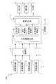
- FIG. 1 is a block diagram illustrating an overall configuration of a biological state determination apparatus according to an embodiment of the present invention.
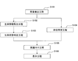
- FIG. 2 is a flowchart showing an operation flow of the biological state determination apparatus.
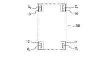
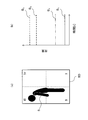
- FIG. 3 is an explanatory diagram showing the arrangement of the load detector with respect to the bed.
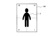
- FIG. 4 is an explanatory diagram showing the arrangement of four load detection areas defined on the upper surface of the bed.
- FIG. 5 shows an example of a load signal output from the load detector.
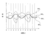
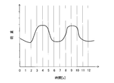
- FIG. 6 shows an example of respiration information extracted from the load signal.
- FIG. 7 is a waveform diagram showing an example of respiratory information corresponding to a normal respiratory state.
- FIG. 8 is a waveform diagram showing an example of respiratory information corresponding to the snoring state.
- FIG. 1 is a block diagram illustrating an overall configuration of a biological state determination apparatus according to an embodiment of the present invention.
- FIG. 2 is a flowchart showing an operation flow of the biological state determination apparatus.
- FIG. 3 is an
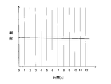
- FIG. 9 is a waveform diagram showing an example of respiratory information corresponding to the apnea state.
- FIG. 10 is a flowchart illustrating an example of a respiratory state determination operation by the biological state determination unit.
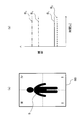
- 11 (a) and 11 (b) show the relationship between the posture of the subject and the load signal, and FIG. 11 (a) shows the state in which the subject lies on his back (sleeps on his back).
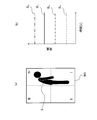
- Shows an example of a load signal when the subject is in the posture of FIG. 12 (a) and 12 (b) show other relationships between the posture of the subject and the load signal, and
- FIG. 12 (a) shows that the subject lay down with his left half down (sleeps sideways).
- FIG. 12 (a) shows that the subject lay down with his left half down (sleeps sideways).
- FIG. 12 (b) shows an example of the load signal when the subject is in the posture of FIG. 12 (a).
- 13 (a) and 13 (b) show still another relationship between the posture of the subject and the load signal.
- FIG. 13 (a) shows a state in which the subject is lying on the right half down.
- (B) shows an example of a load signal when the subject is in the posture of FIG.
- FIG. 14A, FIG. 14B, FIG. 14C, and FIG. 14D show examples of various body positions specified by the body position specifying unit.
- FIG. 15 shows an example of information displayed on the display device.
- FIG. 16 is a block diagram illustrating an overall configuration of a biological state determination apparatus according to a modification.
- the biological state determination apparatus 100 of the present embodiment mainly includes a load detection unit 1, a control unit 3, a storage unit 4, and a display unit 5.
- An A / D conversion unit 2 is connected between the load detection unit 1 and the control unit 3. Further, a notification unit 6 and an input unit 7 are connected to the control unit 3.
- the load detector 1 includes four load detectors 11, 12, 13, and 14. Each of the load detectors 11, 12, 13, and 14 is a load detector that detects a load using a beam-type load cell. Such a load detector is described in, for example, Japanese Patent No. 4829020 and Japanese Patent No. 4002905. Each of the load detectors 11, 12, 13, and 14 is connected to the A / D converter 2 by wiring.
- the A / D converter 2 includes an A / D converter that converts an analog signal from the load detector 1 into a digital signal, and is connected to the load detector 1 and the controller 3 by wiring.
- the control unit 3 is a dedicated or general-purpose computer, and a biological information extraction unit 31, a biological state determination unit 32, a body position specifying unit 33, and an association unit 34 are built therein.
- the storage unit 4 is a storage device that stores data used in the biological state determination device 100, and for example, a hard disk (magnetic disk), a semiconductor memory, or the like can be used.
- the display unit 5 is a monitor such as a liquid crystal monitor that displays information output from the control unit 3 to the user of the biological state determination device 100.
- the notification unit 6 includes a device that performs predetermined notification visually or audibly based on information from the control unit 3, for example, a speaker.
- the input unit 7 is an interface for performing a predetermined input to the control unit 3 and can be a keyboard and a mouse.
- the determination of the biological state of the subject S and the identification of the posture of the subject S using the biological state determination device 100 are performed by a load detection step (S101) for detecting the load of the subject S, and the subject's living body (details). Takes out information on breathing and body position, takes out the biological information (S102), and determines the biological state (specifically, the respiratory state) of the subject S based on the extracted biological information ( S103), a body posture information step (S104) for identifying the posture of the subject from the detected load, a biological state information by associating the biological state of the subject determined in the biological state determination step with the posture of the subject identified in the posture identifying step. Are included in the associating step (S105) and the display step (S106) for displaying the obtained biological state information.
- the four load detectors 11, 12, 13, and 14 of the load detection part 1 are arrange
- the load applied to the upper surface of the bed BD is four load detectors 11, 12, 13 and 14 are detected in a distributed manner.
- the rectangular upper surface of the bed BD is equally divided into four rectangular areas I to IV by dividing it vertically and horizontally, and is supine at the center on the bed BD.
- the load applied to the region I where the lower left half of the subject S is located is mainly detected by the load detector 11, and the load applied to the region II where the lower right half of the subject S in the same state is located is mainly Is detected by the load detector 12.
- the load applied to the region III where the upper right half of the subject S lying on the bed BD is located is mainly detected by the load detector 13, and the region IV where the upper left half of the subject S in the same state is located.
- the load applied to is mainly detected by the load detector 14.
- the load detectors 11, 12, 13, and 14 detect the load, for example, every 0.1 second, and output it to the A / D converter 2 as an analog signal including the load information.
- the A / D conversion unit 2 converts the received analog signal into a digital signal, and outputs the digital signal to the control unit 3 as a digital signal including load information (hereinafter, “load signal”).
- FIG. 1 An example of a load signal sent from the A / D conversion unit 2 to the control unit 3 is shown in FIG.
- the signals S 1 , S 2 , S 3 , and S 4 output from the load detectors 11, 12, 13, and 14 each include a signal including respiratory information of the subject S and a signal including body posture information of the subject S. Yes.
- attention is paid to a signal including this respiration information and it is handled as a signal indicating a biological state. Details thereof will be described later.
- the biological information extraction unit 31 constructed inside the control unit 3 receives a load signal sent from the A / D conversion unit 2, and from here a signal including the biological information of the subject S (hereinafter simply referred to as “subject information”). "Respiration information” and “Respiration signal”) are separated and extracted.
- the load signal sent from the A / D converter 2 includes respiration information and body position information as described above.
- the respiration information included in the load signal is derived from the change in the position of the center of gravity of the subject S that changes as the subject S breathes. That is, when the subject S breathes, the diaphragm of the subject S moves, and the organ moves in the body of the subject S accordingly. Then, the position of the center of gravity of the subject S moves, and the values of the loads applied by the subject S to the load detectors 11, 12, 13, and 14 slightly change.
- the posture information included in the load signal is derived from the fact that the value of the load applied to the load detectors 11, 12, 13, and 14 changes as the posture of the subject S changes.
- FIG. 5 it is observed that in the section shown on the leftmost side (section of time 0 s to 60 s), the subject S was supine (FIG. 4) with his limbs extended to the center of the bed BD. Has been. At this time, the signal S 4 output from the load detector 14 and the signal S 3 output from the load detector 13 show relatively large values, and the signal S 1 output from the load detector 11 and the load detector 12. Signal S 2 indicates a relatively small value is output from. Further, in FIG. 5, it is observed that the upper half of the subject S is placed in the area III of the bed BD and the lower half of the subject S is placed in the area II in the section shown on the rightmost side (the section of time 120s to 180s). Has been.
- the signal S 3 output from the load detector 13 and the signal S 2 output from the load detector 12 show relatively large values, and the signal S 1 output from the load detector 11 and the load detector 14.
- signal S 4 indicates a relatively small value is output from. That is, it can be seen that the balance of the values of the signals S 1 to S 4 from the load detectors 11 to 14 is a signal that changes in accordance with the posture of the subject S on the bed BD, that is, posture information.
- the respiration information does not appear on a visible scale in FIG. This is because the respiration information is caused by a slight change in the center of gravity caused by the respiration of the subject S, and the fluctuation range of the load value is much smaller than the magnitude of the entire load signal.
- respiration information far smaller than the magnitude of the entire load signal from the load signal. It is known that a person's breathing is about 12 to 20 times per minute. When this is converted into a period, it is about 3 to 5 seconds, and when converted into a frequency, it is about 0.2HZ to 0.33 Hz. On the other hand, it is assumed that the posture of a person is not changed periodically, and the posture continuously changes on a bed with a cycle of 5 seconds or less (frequency of 0.2 Hz or more) during sleep. hard.
- a signal that is displaced within a range of about 0.2 Hz to 0.33 Hz has respiratory information
- a signal that is displaced within a range of less than 0.2 Hz has body position information. Therefore, by extracting a signal in the range of about 0.2 Hz to 0.33 Hz from the load signal, respiratory information can be extracted from the load signal.
- the respiratory information is extracted from the load signal by performing Fourier transform, frequency filter processing, and inverse Fourier transform on the load signal, and extracting a waveform having a frequency in the range of about 0.2 Hz to 0.33 Hz.
- FIG. 6 shows the respiration information BS 1 to BS 4 for 13 seconds extracted from the section from 0 s to 60 s of the load signals S 1 to S 4 shown in FIG.
- BS 1 to BS 4 fluctuate with a period of about 4 to 5 seconds along with the change of the load applied to the regions I to IV.
- the influence of the body position (DC component in FIG. 5) is completely removed.
- the biological information extraction unit 31 selects the information (signal) having the waveform with the largest amplitude among the extracted respiratory information BS 1 to BS 4 because it is considered to be highly reliable, and sends it to the biological state determination unit 32. send.
- the biological state determination unit 32 built inside the control unit 3 receives the respiratory information from the biological information extraction unit 31, and compares this respiratory information with the reference information stored in the storage unit 4. And determining the breathing state of the subject S.
- the storage unit 4 stores respiratory information indicating various respiratory states of the subject S as reference information.
- respiratory information indicating various respiratory states of the subject S as reference information.
- One example is normal breathing information indicating that the subject S is breathing normally, snoring information indicating that the subject S is snoring, and apnea information indicating that the subject S is in an apnea state. is there.
- Normal breathing information is stored as a waveform shown in FIG. 7, for example.
- the normal breath information has a shape close to a sine wave.
- the snoring information is stored, for example, as a waveform shown in FIG.
- the waveform corresponding to snoring information has a shape closer to a rectangular wave than the waveform corresponding to normal breathing information.
- Apnea information is stored as, for example, the shape shown in FIG.
- the biological state determination unit 32 compares the breathing information received from the biological information extraction unit 31 with the snoring information stored in the storage unit 4 to determine whether the waveforms are identical or similar (S321). . This determination can be made, for example, by obtaining a correlation function of both waveforms and comparing this correlation function with a threshold value.
- the biological state determination unit 32 determines that the respiratory state of the subject S is “snoring” (S323), and associates the determination results. The data is sent to the unit 34 (S326). If it is determined that the respiratory information does not match or resemble the snoring information (“NO” in S321), the biological state determination unit 32 proceeds to step S322.
- step S322 the biological state determination unit 32 compares the respiratory information received from the biological information extraction unit 31 with the apnea information stored in the storage unit 4, and determines whether or not they match or are similar ( S322). This determination is performed by the same method as the determination in step S321.
- the biological state determination unit 32 determines that the respiratory state of the subject S is “apnea” (S324), and the determination result Is sent to the associating unit 34 (S326). If it is determined that the respiratory information does not match or resemble the apnea information (“NO” in S322), the biological state determination unit 32 determines that the respiratory state of the subject S is “normal” (S325), and the determination result Is sent to the associating unit 34 (S326).
- the breathing state of normal, apnea, and snoring is determined.
- the present invention is not limited to this, and it is also possible to determine whether the subject is alive or morbid by the breathing information. .
- the body position specifying step S104 is a process in which the body position specifying unit 33 built inside the control unit 3 receives the body position information from the biological information extracting unit 31 and specifies the body position of the subject S in the bed BD.
- the biological information extraction unit 31 sends the load signal received from the A / D conversion unit 2 to the body position specifying unit 33 as body position information as it is.
- the posture information is detected in a much larger order than the respiratory information, even if the load signal including the respiratory information is used as the posture information as it is, it does not affect the identification of the posture. .
- the specific position of the subject S by the posture specifying unit 33 is specifically performed as follows.
- the load detectors 11, 12, 13, and 14 detect the load applied on the bed BD by dividing the load into four regions I to IV. Therefore, when the subject S changes his / her posture on the bed BD, the loads applied to the region I, the region II, the region III, and the region IV change, and thus the detected values of the load detectors 11, 12, 13, and 14, respectively. That is, the load signal changes.
- the body posture specifying unit 33 determines the posture of the subject S based on the correspondence between the load signals S 1 to S 4 received from the biological information extracting unit 31 and the combination of the load signals stored in advance and the posture of the subject S. Identify.
- the body position specifying unit 33 is a combination of the body position of the subject S shown in FIG. 11 (a) (the limbs are straightened with the limbs straight and supine) and the load signals S 1 to S 4 shown in FIG. 11 (b). Are stored in association with each other. Therefore, if the load signal sent from the biometric information extracting unit 31 is the shape or numerical value shown in FIG. 11B or a shape or numerical value close to this, the subject S “extends limbs straight at the center of the bed and lies supine. Is identified.
- the body position specifying unit 33 displays the body posture of the subject S shown in FIG. 12 (a) (the region I and the region IV with the left half down, lying on the side), and FIG. 12 (b). And a combination of the load signals S 1 to S 4 shown in FIG. Therefore, if the load signal sent from the biometric information extraction unit 31 is the shape or numerical value shown in FIG. 12B or a shape or numerical value close to this, the subject S is “in the region I and region IV, To be in a position lying down.
- the body position specifying unit 33 displays the posture of the subject S shown in FIG. 13A (region II and region III, lying on the right side of the body), and load signals S 1 to S shown in FIG. 13B. 4 combinations are stored in association with each other. Therefore, if the load signal sent from the biometric information extraction unit 31 is the shape or numerical value shown in FIG. 13B or a shape or numerical value close to this, the subject S is “in the region II and region III, To be in a position lying down.
- the body position specifying unit 33 is a body posture in which the legs are stretched and supine at the center of the bed, both arms are stretched and both hands are placed above the head (FIG. 14 (a)), the head in the region III, Standing in a prone position (legs lying down) (Fig. 14 (b)), kneeling at the center of the bed, supine, extending both arms, and holding both hands from the head Also, the body is placed on its back (FIG. 14 (c)), and the body is rolled and lying on its side so that the head is located in region III, the torso is located in region IV, and the leg is located in region I (FIG. 14 (d)). ) And various combinations of the load signals S 1 to S 4 are stored. Therefore, various postures of the subject S can be specified based on the load signal sent from the biological information extraction unit 31 and the stored correspondence relationship.
- the posture of the subject S specified by the posture specifying unit 33 is sent to the associating unit 34.
- the associating unit 34 built in the control unit 3 associates the respiratory state of the subject S received from the biological state determining unit 32 with the posture of the subject S received from the body position specifying unit 33.
- the associating unit 34 determines the time (time or start of detection) of the breathing state of the subject S received from the biological state determination unit 32 and the posture of the subject S received from the body position specifying unit 33. (Elapsed time from) to create sleep state information that is a combination of respiratory state and body position.
- the created sleep state information is sent to the display unit 5.
- the display step S106 is a step of visually displaying the sleep state information received by the display unit 5 from the control unit 3 (association unit 34).
- the posture of the subject S is displayed as an image on the monitor of the display unit 5. Therefore, the user can intuitively grasp the posture of the subject S only by looking at the display unit 5. The user can also record the posture image of the subject S in the storage unit 4.
- SAS sleep apnea syndrome
- the current time, the breathing state of the subject S, and the history of the breathing state of the subject S are also displayed on the monitor of the display unit 5. Further, the display unit 5 may display the breathing cycle of the subject S, the number of apneas in the last one hour, and the like.
- the user can also set the notification unit 6 to notify when the subject S reaches a predetermined state. For example, the user can set to notify when the subject S reaches an apnea state 5 times or more per hour.
- the living body state determination apparatus 100 takes out respiratory information from a load signal as a waveform and compares it with reference information stored in advance to determine the respiratory state of the subject S. Therefore, various respiratory states of the subject S such as a normal breathing state, a snoring state, and an apnea state can be suitably determined. Further, by enriching the types of reference information, it is possible to increase the accuracy of determination and at the same time to specify the breathing state of the subject S in detail.
- the living body state determination apparatus 100 of the present embodiment specifies the posture of the subject S based on the correspondence relationship between the combination of detection values from the load detection unit 1 stored in advance and the posture of the subject S. Therefore, various positions of the subject S on the bed BD can be suitably specified. Further, by enhancing the correspondence relationship stored in advance, it is possible to increase the specific accuracy, and at the same time, it is possible to specify the posture more strictly.
- the living body state determination apparatus 100 can graphically display the body position (sleeping phase) of the subject S while sleeping, and can record this. Therefore, it is possible to provide an appropriate diagnosis and treatment opportunity without giving a sense of resistance to a patient who shows a sense of resistance to recording a sleeping figure for diagnostic purposes.
- the biological state determination device 100 creates sleep state information by associating the respiratory state and body position of the subject S in the association unit 34 and displays the sleep state information on the display unit 5. Therefore, the relationship between the respiratory state of the subject S and the posture can be presented to the user. Using this relationship, the doctor can study the respiratory state of the subject S based on the relationship with the posture, or can advise the posture at bedtime for maintaining a good respiratory state.
- the reference information can be prepared in various ways, but the first exemplary method is that, from a large number of subjects S, respiratory information (waveform) during normal breathing, respiratory information during snoring (Waveform), Respiratory information (waveform) at the time of apnea is collected, and based on these, normal breathing information, snoring information, and apnea information for reference are created.
- the normal breathing information for reference has a virtual waveform that is determined by the biological state determination unit 32 as “matching” with all of the breathing information during normal breathing having individual differences collected from a large number of subjects S. The same applies to snoring information and apnea information for reference.
- the capacity of information stored in the storage unit 4 can be reduced.
- the subject S can be divided into groups with various attributes, and reference information can be prepared for each group.
- attributes used here include gender, age, height, weight, average respiratory rate at rest and average pulse rate.
- the subject S may be classified based on whether or not the patient is diagnosed with a past disease (especially a past disease related to a respiratory disease) or sleep apnea syndrome.
- the respiratory state of the subject S is determined after inputting the attributes of the subject S using the input unit 7.
- the biological state determination part 32 performs a biological state determination process using the reference information which satisfy
- a second exemplary method of preparing reference information is to collect reference information from the subject S itself. Specifically, it is as follows.
- the respiratory state of the subject S can be determined without using the biological state determination device 100 of the present embodiment by attaching a respiratory sensor to the subject S 'nose, mouth, chest, and the like. Therefore, the respiration sensor and the biological information determination device 100 of the present embodiment are used in parallel for a predetermined time, and the detection result of the respiration sensor is compared with the respiratory information obtained by the biological information determination device 100 of the present embodiment.
- reference information specific to the subject S can be prepared. This method is advantageous when it is desired to make a more reliable determination on the subject S who needs to continuously determine the respiratory state by the biological state determination apparatus 100 of the present embodiment.
- the biological state determination apparatus 200 according to the modification is different from the biological state determination apparatus 100 according to the embodiment in that an update information collection unit 35 and a reference information editing unit 36 are further built in the control unit 3.
- the update information collection unit 35 collects new update information every time the biological state determination device 200 is used for a new subject S. Specifically, the update information collection unit 35 is used for the determination after the biological state determination unit 32 determines that the breathing state of the subject S is one of a normal breathing state, a snoring state, or an apnea state. Respiratory information of the subject S is received and sent to the storage unit 4 as update information corresponding to the determination result. That is, if the determination result is a normal breathing state, it is sent to the storage unit 4 as normal breathing information, if the determination result is a snoring state, it is sent as snoring information, and if the determination result is an apnea state, it is sent to the storage unit 4.
- the update information collection unit 35 When the attributes (gender, age, etc.) of the subject S are input to the biological state determination device 200, the update information collection unit 35 also sends the attributes of the subject S to the storage unit 4.
- the reference information editing unit 36 improves the reference information already stored in the storage unit 4 based on the new update information sent from the update information collection unit 35.
- reference information can be enriched while using the biological state determination device 200 in the field.
- the load detectors 11, 12, 13, and 14 are not limited to load sensors using beam-type load cells, and for example, force sensors can also be used.
- the number of load detectors is not limited to four. Five or more load detectors may be used with additional legs on the bed BD. Alternatively, load detectors may be arranged on only two or three of the legs of the bed BD.
- the load detector 11, 12, 13 and 14 are arranged under the bed casters C 1 attached to the lower end of the leg of the BD, C 2, C 3, C 4
- Each of the load detectors 11, 12, 13, and 14 may be provided between the four legs of the bed BD and the floor plate of the bed BD, or the four legs of the bed BD can be divided vertically. For example, it may be provided between the upper leg and the lower leg.
- the load detector provided on the bed means the load detector provided between the four legs of the bed BD and the floor plate of the bed BD, the upper leg and the lower leg. Means a load detector provided between the two.
- a signal amplification unit that amplifies the load signal from the load detection unit 1 and a filtering unit that removes noise from the load signal are provided between the load detection unit 1 and the A / D conversion unit 2. May be.
- the living body state determination unit 32 determines whether the breathing state of the subject S is a normal breathing state, a snoring state, or an apnea state, but is not limited thereto.
- the determination performed by the biological state determination unit 32 may be more detailed.
- the subject S sneezes, sneezes, yawns, hiccups, the subject S is speaking, or the subject S laughs. You may determine that.
- the storage unit 4 stores reference information indicating coughing, sneezing, sneezing, and hiccups, and reference information indicating that the user is speaking and laughing.
- the biological information extraction unit 31 sends the load information to the body position specifying unit 33 as it is. However, the biological information extraction unit 31 obtains a difference between the load signal and the respiratory information, and obtains the difference. May be sent to the body position specifying unit 33 as body position information.
- the biometric information extraction unit 31 selects only information (signal) having the largest amplitude of change from the respiration information BS 1 to BS 4 extracted from the load signals S 1 to S 4.
- the biological information extraction unit 31 may select only two of the respiratory information BS 1 to BS 4 having a large change amplitude and send the selected information to the biological state determination unit 32, or the respiratory information BS 1 to BS 4. A plurality of them may be sent to the biological state determination unit 32 as they are.
- the biological state determination unit 32 may compare whether or not each of them matches the reference signal, and the subject based on whether or not all of them match the reference signal. The breathing state of S may be determined.
- the load signal that has passed through the biological information extraction unit 31 is sent to the body position specifying unit 33, but the load signal may be sent directly from the A / D conversion unit 2 to the body position specifying unit 33. Good.
- the biological state determination unit 32 determines whether the breathing information matches or resembles snoring information and determines whether the breathing information matches or resembles apnea information. If they did not match or resembled any of them, the subject S was determined to be in a normal breathing state.
- the biological state determination unit 32 may determine, for example, whether the breathing information matches or is similar to normal breathing information, and whether the breathing information matches or is similar to snoring information, If the respiratory information does not match or resemble any of the information, it may be determined that the subject S is in an apnea state, and further, it may be determined whether the respiration information matches or is similar to the apnea information.
- the step of determining the respiratory state of the subject S by the biological state determination unit 32 can be performed by any suitable procedure including a comparison between the respiratory information and at least one of normal respiratory information, snoring information, apnea information, and the like. .
- the following method can be used to further improve the accuracy of the posture determination of the subject S performed by the posture specifying unit 33.
- the body height of the subject S is specified after inputting the actual height, weight, muscle mass, body fat percentage, and the like of the subject S using the input unit 7.
- the posture specifying unit 33 specifies the posture using the set of correspondences that satisfy the above-described conditions.
- the subject S is made to execute a series of body posture changes according to a specific protocol on the bed BD, and based on this, the correspondence between the body posture and the detected load value, which is peculiar to the subject S, is shown. Is to create.
- the detection of the load signal using the living body state determination apparatus 100 is performed overnight while photographing the sleeping posture of the subject S with a video camera or the like. And a correspondence relationship between the load detection value and the load detection value.
- the biological state determination apparatus 100 of the said embodiment does not need to have the body position specific
- the display unit 5 may display only the breathing state.
- the display unit is not limited to displaying information on the monitor so that the user can visually recognize it.
- the display unit 5 may be a printer that prints and outputs the breathing state of the subject S.
- the blue lamp is turned on in the normal breathing state
- the yellow lamp is turned on in the snoring state
- the red lamp is turned on in the apnea state. You may display using visual expression.
- the display unit 5 may convey the breathing state of the subject S to the user by voice.
- the biological state determination apparatus 100 of the said embodiment does not need to have the display part 5.
- the biological state determination apparatus 100 may include a signal output unit (not shown) for outputting the biological state of the subject S obtained by the control unit 3 to a data logger or the like.
- the biological state of the subject S obtained by the control unit 3 is sent to and stored in a data logger or the like in the form of a video signal, text information, binary information, etc. via the signal output unit.
- the display unit and the signal output unit are collectively referred to as an “output unit”.
- reporting part 6 of the said embodiment performed alerting
- reporting part 6 may be the structure which alert
- the biological state determination apparatus 100 of the said embodiment does not need to have the alerting
- the components connected by wiring may be connected wirelessly.
- the present invention is not limited to the above embodiments, and other forms conceivable within the scope of the technical idea of the present invention are also included in the scope of the present invention. .
- the biological state determination apparatus of the above embodiment extracts biological information indicating the state of the subject's living body included in the output from the load detector, and compares this with reference information prepared in advance to determine the biological state of the subject. Judgment. In this way, by using the reference information, the biological state of each subject can be determined in detail and accurately.
- the living body state determination apparatus of the above embodiment has the body position specifying unit, various body positions of the subject can be appropriately specified and presented to the user.
- the living body state determination apparatus includes the association unit, the relationship between the living body state and the posture of the subject can be presented to the user.
- the living body state determination apparatus of the above embodiment performs output using an image simulating the shape of a human body, the user can easily and intuitively grasp the posture of the subject.
- the biological state determination device of the above-described embodiment is a pathological state including sleep apnea syndrome by determining whether the subject is in a normal breathing state, a snoring state, or an apnea state. It is possible to suitably perform diagnosis and treatment.
- the biological state determination device of the above embodiment includes an information collection unit and an information editing unit, it is possible to enrich reference information used by the biological state determination device at the same time while using the biological state determination device for a subject.
- the living body state determination apparatus includes the notification unit, the user can immediately and reliably know that the subject has entered a predetermined state.
- the biological information indicating the state of the subject's living body, which is included in the output from the load detector, is extracted, and the biological state of the subject is compared with reference information prepared in advance. Judgment. Therefore, by using the reference information, the biological state of each subject can be determined in detail and accurately.
- the living body state determination method of the above-described embodiment performs body posture specification using the body posture specifying unit, various postures of the subject can be suitably specified and presented to the user.
- the biological state determination method of the above embodiment can satisfactorily present the relationship between the biological state and the posture of the subject to the user using the association unit.
- the respiratory rate and the amount of respiratory volume can be quantitatively measured from the change in load distribution, and the respiratory status of hospitalized patients can be continuously measured in a non-invasive and non-contact manner. Can be monitored.
- the nursing record vital record
- the number of night patient checks by the nurse is reduced, and the nurse's workload is reduced.
- the patient's sleep quality can be improved.
Abstract
Provided is a biological condition determination device (100) for determining the biological condition of a subject on a bed. The biological condition determination device (100) has: a plurality of load detectors (11, 12, 13, 14) that are provided to a bed or to legs of the bed and detect the load of the subject; a biological information extraction unit (31) that extracts biological information from the output of the load detectors; a determination unit (32) that compares the biological information which has been extracted with reference information which has been prepared in advance to determine the biological condition of the subject; and an output unit (5) that outputs the biological condition of the subject which has been determined by the determination unit.
Description
本発明は、荷重検出器を使用する生体状態判定装置、及び該生体状態判定装置を使用する生体状態判定方法に関する。
The present invention relates to a biological state determination device that uses a load detector and a biological state determination method that uses the biological state determination device.
ベッド上の患者や被介護者を遠隔地から管理するためのシステムが、病院や介護施設等で活用されている。例えば病院において患者の在床/離床を検知するシステムを使用すれば、ナースステーションの看護師は、患者が病室のベッド上にいるか否かを病室を訪れることなく確認することができる。
A system for remotely managing patients and caregivers on the bed is used in hospitals and nursing care facilities. For example, if a system for detecting the presence / absence of a patient in a hospital is used, the nurse at the nurse station can check whether the patient is on the bed of the patient room without visiting the patient room.
特許文献1は、ベッドの床板にセンサマットを配置し、センサマットからの出力に基づいて、ベッド上の被介護者の臥床/離床を検出したり、被介護者の呼吸の周波数の変化、呼吸のスペクトルのピーク強度等の呼吸情報を検出する介護支援システムを開示している。
In Patent Document 1, a sensor mat is arranged on a floor plate of a bed, and based on an output from the sensor mat, a caregiver's bed rest / leaving on the bed is detected, a change in the frequency of breathing of the cared person, breathing Discloses a care support system that detects respiratory information such as the peak intensity of the spectrum.
特許文献2は、ベッドの4本の脚の下にそれぞれ荷重検出手段を配置し、この荷重検出手段からの出力に基づきベッド上に人が存在しているか否かを判定する在床検知方法を開示している。また特許文献2は、荷重検出手段によって人の呼吸の有無を検知して人の呼吸の有無の判断を行い、在床検知の精度を高めることを開示している。
Patent Document 2 discloses an in-bed detection method in which a load detection unit is disposed under each of four legs of a bed and whether or not a person is present on the bed based on an output from the load detection unit. Disclosure. Patent Document 2 discloses that the presence or absence of a person's breathing is detected by the load detection means to determine the presence or absence of a person's breathing, thereby improving the accuracy of bed detection.
特許文献1に開示される介護支援システムでは、ベッドの床板にセンサマットを配置する必要があるが、センサマットは比較的高価であり、かつ耐用期間が短いため、ランニングコストが高額となる。一方で、特許文献2に開示される在床検知システムはセンサマットは使用しないが、被験者の呼吸の有無を検知できるのみであり、被験者のより詳しい呼吸状態を知ることができない。
In the care support system disclosed in Patent Document 1, it is necessary to arrange a sensor mat on the floor of the bed. However, the sensor mat is relatively expensive and has a short service life, resulting in a high running cost. On the other hand, the occupancy detection system disclosed in Patent Document 2 does not use a sensor mat, but can only detect the presence or absence of the subject's breathing and cannot know a more detailed breathing state of the subject.
本発明は上記の課題を解決することを目的としており、ベッド上の被験者の生体状態を簡易に詳しく判定することのできる生体状態判定装置、及び生体状態判定方法を提供することを目的とする。
The present invention aims to solve the above-described problems, and an object thereof is to provide a biological state determination device and a biological state determination method that can easily and in detail determine the biological state of a subject on a bed.
本発明の第1の態様に従えば、
ベッド上の被験者の生体状態を判定する生体状態判定装置であって、
ベッド又はベッドの脚下に設けられ、前記被験者の荷重を検出する複数の荷重検出器と、
前記荷重検出器の出力から生体情報を取り出す生体情報取出部と、
前記取り出された生体情報と予め用意した参照情報とを比較して前記被験者の生体状態を判定する判定部と、
前記判定部により判定された被験者の生体状態を出力する出力部とを有する生体状態判定装置が提供される。 According to the first aspect of the present invention,
A biological state determination device for determining a biological state of a subject on a bed,
A plurality of load detectors provided under the bed or the leg of the bed and detecting the load of the subject;
A biological information extraction unit for extracting biological information from the output of the load detector;
A determination unit that determines the biological state of the subject by comparing the extracted biological information with reference information prepared in advance;
There is provided a biological state determination apparatus including an output unit that outputs a biological state of a subject determined by the determination unit.
本発明の生体状態判定装置は、前記荷重検出器の出力に基づいて前記被験者の体位を求める体位特定部を更に有してもよく、前記出力部が、前記体位特定部により求められた被験者の体位を出力してもよい。
The living body state determination apparatus of the present invention may further include a body position specifying unit that determines the body position of the subject based on the output of the load detector, and the output unit of the subject determined by the body position specifying unit. You may output your posture.
本発明の生体状態判定装置は、前記判定部により判定された前記被験者の生体状態と、前記体位特定部により求められた前記被験者の体位とを関連付ける関連付け部を更に有してもよい。
The biological state determination apparatus of the present invention may further include an association unit that associates the biological state of the subject determined by the determination unit with the posture of the subject determined by the body position specifying unit.
本発明の生体状態判定装置において、前記出力部は、前記求めた体位を、人体の形状を模した映像を用いて出力してもよい。
In the biological state determination device of the present invention, the output unit may output the obtained body position using an image simulating the shape of a human body.
本発明の生体状態判定装置において、前記判定部は、前記被験者の生体状態の一つである呼吸状態が、平常呼吸状態、いびき状態、無呼吸状態のいずれであるかを判定してもよい。
In the biological state determination device of the present invention, the determination unit may determine whether a respiratory state that is one of the biological states of the subject is a normal respiratory state, a snoring state, or an apnea state.
本発明の生体状態判定装置は、前記参照情報を記憶する記憶部を更に有しても良く、前記判定に使用した生体情報と、前記判定の結果とを関連付けて更新情報を作成する情報収集部を更に有しても良く、前記更新情報に基づいて前記参照情報を変更する情報編集部を更に有してもよい。
The biological state determination device of the present invention may further include a storage unit that stores the reference information, and an information collection unit that creates update information by associating the biological information used for the determination with the determination result And an information editing unit that changes the reference information based on the update information.
本発明の生体状態判定装置は、前記判定の結果に基づいて報知を行う報知部を更に有してもよい。
The biological state determination device of the present invention may further include a notification unit that performs notification based on the determination result.
本発明の第2の態様に従えば、
ベッド上の被験者の生体状態を生体状態判定装置により判定する方法であって、
ベッド又はベッドの脚下に配置された複数の荷重検出器により前記被験者の荷重を検出することと、
生体情報取出部により前記荷重検出器の出力から生体情報を取り出すことと、
判定部により前記取り出された生体情報と予め用意した参照情報とを比較して前記被験者の生体状態を判定することを有する方法が提供される。 According to the second aspect of the present invention,
A method of determining a biological state of a subject on a bed by a biological state determination device,
Detecting the load of the subject by a plurality of load detectors arranged under the bed or under the legs of the bed;
Extracting biological information from the output of the load detector by a biological information extraction unit;
There is provided a method including determining the biological state of the subject by comparing the extracted biological information with reference information prepared in advance by a determination unit.
本発明の生体状態判定方法は、体位特定部により、前記荷重検出器の出力に基づいて前記被験者の体位を求めることを更に有してもよい。
The biological condition determination method of the present invention may further include obtaining the posture of the subject based on the output of the load detector by the posture specifying unit.
本発明の生体状態判定方法は、関連付け部により、前記判定された前記被験者の生体状態と、前記求められた前記被験者の体位とを関連付けることを更に有してもよい。
The biological state determination method of the present invention may further include associating the determined biological state of the subject with the determined posture of the subject by an association unit.
本発明の生体状態判定装置及び生体状態判定方法によれば、センサマットやその他の高額で複雑な装置を使用することなくベッド上の被験者の生体状態を詳しく判定することができる。
According to the biological state determination device and biological state determination method of the present invention, the biological state of the subject on the bed can be determined in detail without using a sensor mat or other expensive and complicated device.
<第1実施形態>
図1~図16を参照して、本発明の実施形態について説明する。 <First Embodiment>
An embodiment of the present invention will be described with reference to FIGS.
図1~図16を参照して、本発明の実施形態について説明する。 <First Embodiment>
An embodiment of the present invention will be described with reference to FIGS.
図1に示す通り、本実施形態の生体状態判定装置100は、荷重検出部1、制御部3、記憶部4、表示部5を主に有する。荷重検出部1と制御部3との間には、A/D変換部2が接続されている。制御部3には更に、報知部6及び入力部7が接続されている。
As shown in FIG. 1, the biological state determination apparatus 100 of the present embodiment mainly includes a load detection unit 1, a control unit 3, a storage unit 4, and a display unit 5. An A / D conversion unit 2 is connected between the load detection unit 1 and the control unit 3. Further, a notification unit 6 and an input unit 7 are connected to the control unit 3.
荷重検出部1は、4つの荷重検出器11、12、13、14を備える。荷重検出器11、12、13、14のそれぞれは、ビーム形のロードセルを用いて荷重を検出する荷重検出器である。このような荷重検出器は例えば、特許第4829020号や特許第4002905号に記載されている。荷重検出器11、12、13、14はそれぞれ、配線によりA/D変換部2に接続されている。
The load detector 1 includes four load detectors 11, 12, 13, and 14. Each of the load detectors 11, 12, 13, and 14 is a load detector that detects a load using a beam-type load cell. Such a load detector is described in, for example, Japanese Patent No. 4829020 and Japanese Patent No. 4002905. Each of the load detectors 11, 12, 13, and 14 is connected to the A / D converter 2 by wiring.
A/D変換部2は、荷重検出器1からのアナログ信号をデジタル信号に変換するA/D変換器を備え、荷重検出部1と制御部3にそれぞれ配線で接続されている。
The A / D converter 2 includes an A / D converter that converts an analog signal from the load detector 1 into a digital signal, and is connected to the load detector 1 and the controller 3 by wiring.
制御部3は、専用又は汎用のコンピュータであり、内部に生体情報取出部31、生体状態判定部32、体位特定部33、及び関連付け部34が構築されている。
The control unit 3 is a dedicated or general-purpose computer, and a biological information extraction unit 31, a biological state determination unit 32, a body position specifying unit 33, and an association unit 34 are built therein.
記憶部4は、生体状態判定装置100において使用されるデータを記憶する記憶装置であり、例えばハードディスク(磁気ディスク)や半導体メモリ等を用いることができる。表示部5は、制御部3から出力される情報を生体状態判定装置100の使用者に表示する液晶モニタ等のモニタである。
The storage unit 4 is a storage device that stores data used in the biological state determination device 100, and for example, a hard disk (magnetic disk), a semiconductor memory, or the like can be used. The display unit 5 is a monitor such as a liquid crystal monitor that displays information output from the control unit 3 to the user of the biological state determination device 100.
報知部6は、制御部3からの情報に基づいて所定の報知を視覚的又は聴覚的に行う装置、例えばスピーカを備える。入力部7は、制御部3に対して所定の入力を行うためのインターフェイスであり、キーボード及びマウスにし得る。
The notification unit 6 includes a device that performs predetermined notification visually or audibly based on information from the control unit 3, for example, a speaker. The input unit 7 is an interface for performing a predetermined input to the control unit 3 and can be a keyboard and a mouse.
次に、生体状態判定装置100を使用してベッド上の被験者の生体状態を判定し、体位を特定する動作について説明する。
Next, the operation of determining the biological state of the subject on the bed using the biological state determination device 100 and specifying the body position will be described.
生体状態判定装置100を使用した被験者Sの生体状態の判定及び体位の特定は、図2に示す通り、被験者Sの荷重を検出する荷重検出工程(S101)、検出した荷重から被験者の生体(詳しくは、呼吸)と体位に関する情報を取り出し、その生体情報を取り出す生体情報取出工程(S102)、取り出した生体情報に基づいて被験者Sの生体状態(詳しくは呼吸状態)を判定する生体状態判定工程(S103)、検出した荷重から被験者の体位を特定する体位特定工程(S104)、生体状態判定工程で判定された被験者の生体状態と体位特定工程で特定された被験者の体位とを関連付けて生体状態情報を作成する関連付け工程(S105)、得られた生体状態情報を表示する表示工程(S106)の各工程を含む。
As shown in FIG. 2, the determination of the biological state of the subject S and the identification of the posture of the subject S using the biological state determination device 100 are performed by a load detection step (S101) for detecting the load of the subject S, and the subject's living body (details). Takes out information on breathing and body position, takes out the biological information (S102), and determines the biological state (specifically, the respiratory state) of the subject S based on the extracted biological information ( S103), a body posture information step (S104) for identifying the posture of the subject from the detected load, a biological state information by associating the biological state of the subject determined in the biological state determination step with the posture of the subject identified in the posture identifying step. Are included in the associating step (S105) and the display step (S106) for displaying the obtained biological state information.
<荷重検出工程>
荷重検出工程S101を行うために、荷重検出部1の4つの荷重検出器11、12、13、14は、被験者が使用するベッドの脚の下に配置される。具体的には荷重検出器11、12、13、14は、図3に示す通り、ベッドBDの四隅の脚の下端部に取り付けられたキャスターC1、C2、C3、C4の下にそれぞれ配置される。 <Load detection process>
In order to perform load detection process S101, the four load detectors 11, 12, 13, and 14 of the load detection part 1 are arrange | positioned under the leg | leg of the bed which a test subject uses. Specifically, as shown in FIG. 3, the load detectors 11, 12, 13, and 14 are below the casters C 1 , C 2 , C 3 , and C 4 attached to the lower ends of the legs at the four corners of the bed BD. Each is arranged.
荷重検出工程S101を行うために、荷重検出部1の4つの荷重検出器11、12、13、14は、被験者が使用するベッドの脚の下に配置される。具体的には荷重検出器11、12、13、14は、図3に示す通り、ベッドBDの四隅の脚の下端部に取り付けられたキャスターC1、C2、C3、C4の下にそれぞれ配置される。 <Load detection process>
In order to perform load detection process S101, the four
荷重検出器11、12、13、14を、キャスターC1、C2、C3、C4の下にそれぞれ配置することにより、ベッドBDの上面に加えられる荷重は、4つの荷重検出器11、12、13、14に分散して検知される。具体的には、図4に示す通りベッドBDの矩形状の上面は、縦及び横にそれぞれ2分割することで4つの矩形領域I~IVに均等に分割され、ベッドBD上の中央部で仰臥する(仰向けに寝る)被験者Sの左下半身が位置する領域Iに加えられる荷重は主に荷重検出器11により検出され、同状態の被験者Sの右下半身が位置する領域IIに加えられる荷重は主に荷重検出器12により検出される。同様に、ベッドBD上の中央部で仰臥する被験者Sの右上半身が位置する領域IIIに加えられる荷重は主に荷重検出器13により検出され、同状態の被験者Sの左上半身が位置する領域IVに加えられる荷重は主に荷重検出器14により検出される。
By placing the load detectors 11, 12, 13, 14 under the casters C 1 , C 2 , C 3 , C 4 respectively, the load applied to the upper surface of the bed BD is four load detectors 11, 12, 13 and 14 are detected in a distributed manner. Specifically, as shown in FIG. 4, the rectangular upper surface of the bed BD is equally divided into four rectangular areas I to IV by dividing it vertically and horizontally, and is supine at the center on the bed BD. The load applied to the region I where the lower left half of the subject S is located is mainly detected by the load detector 11, and the load applied to the region II where the lower right half of the subject S in the same state is located is mainly Is detected by the load detector 12. Similarly, the load applied to the region III where the upper right half of the subject S lying on the bed BD is located is mainly detected by the load detector 13, and the region IV where the upper left half of the subject S in the same state is located. The load applied to is mainly detected by the load detector 14.
荷重検出器11、12、13、14は、例えばそれぞれ0.1秒ごとに荷重を検出して、荷重情報を含むアナログ信号としてA/D変換部2に出力する。A/D変換部2は、受け取ったアナログ信号をデジタル信号に変換し、荷重情報を含むデジタル信号(以下「荷重信号」)として制御部3に出力する。
The load detectors 11, 12, 13, and 14 detect the load, for example, every 0.1 second, and output it to the A / D converter 2 as an analog signal including the load information. The A / D conversion unit 2 converts the received analog signal into a digital signal, and outputs the digital signal to the control unit 3 as a digital signal including load information (hereinafter, “load signal”).
A/D変換部2から制御部3に送られる荷重信号の一例を図5に示す。荷重信号は、荷重検出器11から出力された信号S1(実線)、荷重検出器12から出力された信号S2(破線)、荷重検出器13から出力された信号S3(一点鎖線)、荷重検出器14から出力された信号S4(二点鎖線)の4つを含む。荷重検出器11、12、13、14から出力された信号S1、S2、S3、S4は、それぞれ被験者Sの呼吸情報を含む信号と被験者Sの体位情報を含む信号とを含んでいる。本発明では、この呼吸情報を含む信号に着目し、生体状態を示す信号として取り扱う。またその詳細については後述する。
An example of a load signal sent from the A / D conversion unit 2 to the control unit 3 is shown in FIG. Load signal, signal S 1 output from the load detector 11 (solid line), a signal S 2 output from the load detector 12 (dashed line), the signal S 3 output from the load detector 13 (dashed line), It includes four signals S 4 (two-dot chain line) output from the load detector 14. The signals S 1 , S 2 , S 3 , and S 4 output from the load detectors 11, 12, 13, and 14 each include a signal including respiratory information of the subject S and a signal including body posture information of the subject S. Yes. In the present invention, attention is paid to a signal including this respiration information, and it is handled as a signal indicating a biological state. Details thereof will be described later.
<生体情報取出工程>
生体情報取出工程S102では、制御部3の内部に構築された生体情報取出部31が、A/D変換部2から送られる荷重信号を受け取り、ここから被験者Sの生体情報を含む信号(以下単に「呼吸情報」、「呼吸信号」と呼ぶ)を分離して取り出す。 <Biological information retrieval process>
In the biological information extraction step S102, the biologicalinformation extraction unit 31 constructed inside the control unit 3 receives a load signal sent from the A / D conversion unit 2, and from here a signal including the biological information of the subject S (hereinafter simply referred to as “subject information”). "Respiration information" and "Respiration signal") are separated and extracted.
生体情報取出工程S102では、制御部3の内部に構築された生体情報取出部31が、A/D変換部2から送られる荷重信号を受け取り、ここから被験者Sの生体情報を含む信号(以下単に「呼吸情報」、「呼吸信号」と呼ぶ)を分離して取り出す。 <Biological information retrieval process>
In the biological information extraction step S102, the biological
ここでまず、A/D変換部2から送られる荷重信号について、その詳細を説明する。
First, the details of the load signal sent from the A / D converter 2 will be described.
A/D変換部2から送られる荷重信号は、上述の通り、呼吸情報と体位情報とを含んでいる。このうち荷重信号に含まれる呼吸情報は、被験者Sの呼吸に伴って変化する被験者Sの重心位置の変化に由来する。すなわち、被験者Sが呼吸をすると被験者Sの横隔膜が移動し、これに伴って被験者Sの体内で臓器が移動する。すると、被験者Sの重心位置が移動し、被験者Sによって荷重検出器11、12、13、14に加えられる荷重の値がそれぞれわずかに変化する。同様に、荷重信号に含まれる体位情報は、被験者Sの体位の変化に伴って荷重検出器11、12、13、14に加えられる荷重の値がそれぞれ変化することに由来する。
The load signal sent from the A / D converter 2 includes respiration information and body position information as described above. Among these, the respiration information included in the load signal is derived from the change in the position of the center of gravity of the subject S that changes as the subject S breathes. That is, when the subject S breathes, the diaphragm of the subject S moves, and the organ moves in the body of the subject S accordingly. Then, the position of the center of gravity of the subject S moves, and the values of the loads applied by the subject S to the load detectors 11, 12, 13, and 14 slightly change. Similarly, the posture information included in the load signal is derived from the fact that the value of the load applied to the load detectors 11, 12, 13, and 14 changes as the posture of the subject S changes.
具体的には、図5において、最も左側に示される区間(時間0s~60sの区間)においては、被験者SはベッドBDの中央に手足を伸ばして仰臥(図4)、していたことが観察されている。このとき、荷重検出器14から出力された信号S4及び荷重検出器13から出力された信号S3が比較的大きな値を示し、荷重検出器11から出力された信号S1及び荷重検出器12から出力された信号S2が比較的小さな値を示している。また、図5において、最も右側に示される区間(時間120s~180sの区間)においては、被験者Sの上半身がベッドBDの領域IIIに、被験者Sの下半身が領域IIに置かれていたことが観察されている。この時、荷重検出器13から出力された信号S3及び荷重検出器12から出力された信号S2が比較的大きな値を示し、荷重検出器11から出力された信号S1及び荷重検出器14から出力された信号S4が比較的小さな値を示している。すなわち、荷重検出器11~14からの信号S1~S4の値のバランスが、ベッドBD上の被験者Sの体位に応じて変化する信号、即ち体位情報であることが分かる。
Specifically, in FIG. 5, it is observed that in the section shown on the leftmost side (section of time 0 s to 60 s), the subject S was supine (FIG. 4) with his limbs extended to the center of the bed BD. Has been. At this time, the signal S 4 output from the load detector 14 and the signal S 3 output from the load detector 13 show relatively large values, and the signal S 1 output from the load detector 11 and the load detector 12. signal S 2 indicates a relatively small value is output from. Further, in FIG. 5, it is observed that the upper half of the subject S is placed in the area III of the bed BD and the lower half of the subject S is placed in the area II in the section shown on the rightmost side (the section of time 120s to 180s). Has been. At this time, the signal S 3 output from the load detector 13 and the signal S 2 output from the load detector 12 show relatively large values, and the signal S 1 output from the load detector 11 and the load detector 14. signal S 4 indicates a relatively small value is output from. That is, it can be seen that the balance of the values of the signals S 1 to S 4 from the load detectors 11 to 14 is a signal that changes in accordance with the posture of the subject S on the bed BD, that is, posture information.
一方、呼吸情報は、図5においては目視できるスケールでは表れていない。これは、呼吸情報は被験者Sの呼吸に伴って生じるわずかな重心変化に起因しており、荷重の値の変動幅は、荷重信号全体の大きさに比較してはるかに小さいためである。
On the other hand, the respiration information does not appear on a visible scale in FIG. This is because the respiration information is caused by a slight change in the center of gravity caused by the respiration of the subject S, and the fluctuation range of the load value is much smaller than the magnitude of the entire load signal.
本発明の方法に従って、荷重信号から、荷重信号全体の大きさに比較してはるかに小さい呼吸情報を取り出すことができる。人の呼吸は1分間におよそ12~20回程度であることが知られている。これを周期に換算すると3秒~5秒程度であり、周波数に換算すると0.2HZ~0.33Hz程度である。一方で人の体位の変化は周期的に行われるものではなく、睡眠中に、ベッド上において、5秒以下の周期(0.2Hz以上の周波数)で継続的に体位が変化することは想定し難い。したがって、荷重信号のうち、約0.2Hz~0.33Hzの範囲で変位する信号は呼吸情報を有し、0.2Hz未満の範囲で変位する信号は体位情報を有していると考えられる。したがって、荷重信号から約0.2Hz~0.33Hzの範囲の信号を抽出することで、荷重信号から呼吸情報を取り出すことができる。
In accordance with the method of the present invention, it is possible to extract respiration information far smaller than the magnitude of the entire load signal from the load signal. It is known that a person's breathing is about 12 to 20 times per minute. When this is converted into a period, it is about 3 to 5 seconds, and when converted into a frequency, it is about 0.2HZ to 0.33 Hz. On the other hand, it is assumed that the posture of a person is not changed periodically, and the posture continuously changes on a bed with a cycle of 5 seconds or less (frequency of 0.2 Hz or more) during sleep. hard. Therefore, among the load signals, a signal that is displaced within a range of about 0.2 Hz to 0.33 Hz has respiratory information, and a signal that is displaced within a range of less than 0.2 Hz has body position information. Therefore, by extracting a signal in the range of about 0.2 Hz to 0.33 Hz from the load signal, respiratory information can be extracted from the load signal.
荷重信号からの呼吸情報の取り出しは、具体的には例えば、荷重信号に対してフーリエ変換、周波数フィルタ処理、逆フーリエ変換を行い、周波数が約0.2Hz~0.33Hzの範囲の波形を取り出すことにより行う。
Specifically, for example, the respiratory information is extracted from the load signal by performing Fourier transform, frequency filter processing, and inverse Fourier transform on the load signal, and extracting a waveform having a frequency in the range of about 0.2 Hz to 0.33 Hz. By doing.
上記の工程により、図5に示す荷重信号S1~S4の0s~60sの区間から取り出された13秒分の呼吸情報BS1~BS4を図6に示す。図6においては、BS1~BS4は、領域I~IVに加えられた荷重の変化とともに約4~5秒の周期で変動している。また、それぞれ体位の影響(図5におけるDC成分)が完全に取り除かれている。
FIG. 6 shows the respiration information BS 1 to BS 4 for 13 seconds extracted from the section from 0 s to 60 s of the load signals S 1 to S 4 shown in FIG. In FIG. 6, BS 1 to BS 4 fluctuate with a period of about 4 to 5 seconds along with the change of the load applied to the regions I to IV. In addition, the influence of the body position (DC component in FIG. 5) is completely removed.
生体情報取出部31は、取り出した呼吸情報BS1~BS4のうち、最も振幅の大きい波形を有する情報(信号)が信頼性が高いと考えられるためこれを選択し、生体状態判定部32に送る。
The biological information extraction unit 31 selects the information (signal) having the waveform with the largest amplitude among the extracted respiratory information BS 1 to BS 4 because it is considered to be highly reliable, and sends it to the biological state determination unit 32. send.
<生体状態判定工程>
生体状態判定工程S103は、制御部3の内部に構築された生体状態判定部32が生体情報取出部31から呼吸情報を受け取り、この呼吸情報と記憶部4に記憶された参照情報とを比較して被験者Sの呼吸状態を判定する工程である。 <Biological state determination process>
In the biological state determination step S103, the biologicalstate determination unit 32 built inside the control unit 3 receives the respiratory information from the biological information extraction unit 31, and compares this respiratory information with the reference information stored in the storage unit 4. And determining the breathing state of the subject S.
生体状態判定工程S103は、制御部3の内部に構築された生体状態判定部32が生体情報取出部31から呼吸情報を受け取り、この呼吸情報と記憶部4に記憶された参照情報とを比較して被験者Sの呼吸状態を判定する工程である。 <Biological state determination process>
In the biological state determination step S103, the biological
記憶部4には、参照情報として、被験者Sの様々な呼吸状態を示す呼吸情報が記憶されている。その一例は、被験者Sが平常の呼吸を行っていることを示す平常呼吸情報、被験者Sがいびきをかいていることを示すいびき情報、被験者Sが無呼吸状態であることを示す無呼吸情報である。
The storage unit 4 stores respiratory information indicating various respiratory states of the subject S as reference information. One example is normal breathing information indicating that the subject S is breathing normally, snoring information indicating that the subject S is snoring, and apnea information indicating that the subject S is in an apnea state. is there.
平常呼吸情報は、例えば図7に示す波形として記憶されている。平常呼吸情報は正弦波に近い形状を有する。いびき情報は、例えば図8に示す波形として記憶されている。いびき情報に対応する波形は、平常呼吸情報に対応する波形よりも矩形波に近い形状を有している。無呼吸情報は、例えば図9に示す形状として記憶されている。
Normal breathing information is stored as a waveform shown in FIG. 7, for example. The normal breath information has a shape close to a sine wave. The snoring information is stored, for example, as a waveform shown in FIG. The waveform corresponding to snoring information has a shape closer to a rectangular wave than the waveform corresponding to normal breathing information. Apnea information is stored as, for example, the shape shown in FIG.
生体状態判定部32により被験者Sの呼吸状態を判定する手順の一例は図10に示す通りである。生体状態判定部32は、まず生体情報取出部31から受け取った呼吸情報と記憶部4に記憶されたいびき情報とを比較して両者の波形が一致又は類似するか否かを判断する(S321)。この判断は例えば、両波形の相関関数を求め、この相関関数を閾値と比較することにより行うことができる。
An example of a procedure for determining the respiratory state of the subject S by the biological state determination unit 32 is as shown in FIG. First, the biological state determination unit 32 compares the breathing information received from the biological information extraction unit 31 with the snoring information stored in the storage unit 4 to determine whether the waveforms are identical or similar (S321). . This determination can be made, for example, by obtaining a correlation function of both waveforms and comparing this correlation function with a threshold value.
呼吸情報がいびき情報に一致又は類似すると判断した場合(S321の「YES」)は、生体状態判定部32は被験者Sの呼吸状態が「いびき」であると判断し(S323)、判断結果を関連付け部34に送る(S326)。呼吸情報がいびき情報に一致及び類似しないと判断した場合(S321の「NO」)は、生体状態判定部32は工程S322に進む。
When it is determined that the respiratory information matches or resembles snoring information (“YES” in S321), the biological state determination unit 32 determines that the respiratory state of the subject S is “snoring” (S323), and associates the determination results. The data is sent to the unit 34 (S326). If it is determined that the respiratory information does not match or resemble the snoring information (“NO” in S321), the biological state determination unit 32 proceeds to step S322.
工程S322において、生体状態判定部32は、生体情報取出部31から受け取った呼吸情報と記憶部4に記憶された無呼吸情報とを比較して両者が一致又は類似するか否かを判断する(S322)。この判断は、工程S321における判断と同じ方法で行われる。
In step S322, the biological state determination unit 32 compares the respiratory information received from the biological information extraction unit 31 with the apnea information stored in the storage unit 4, and determines whether or not they match or are similar ( S322). This determination is performed by the same method as the determination in step S321.
呼吸情報が無呼吸情報に一致又は類似すると判断した場合(S322の「YES」)は、生体状態判定部32は被験者Sの呼吸状態が「無呼吸」であると判断し(S324)、判断結果を関連付け部34に送る(S326)。呼吸情報が無呼吸情報に一致及び類似しないと判断した場合(S322の「NO」)は、生体状態判定部32は被験者Sの呼吸状態が「平常」であると判断し(S325)、判断結果を関連付部34に送る(S326)。
When it is determined that the respiratory information matches or is similar to the apnea information (“YES” in S322), the biological state determination unit 32 determines that the respiratory state of the subject S is “apnea” (S324), and the determination result Is sent to the associating unit 34 (S326). If it is determined that the respiratory information does not match or resemble the apnea information (“NO” in S322), the biological state determination unit 32 determines that the respiratory state of the subject S is “normal” (S325), and the determination result Is sent to the associating unit 34 (S326).
本実施例では、平常、無呼吸、いびき、の呼吸状態の判断をしているが、これに限られず、呼吸情報により、被験者の生存や、病的状態か否かの判断をすることもできる。
In this embodiment, the breathing state of normal, apnea, and snoring is determined. However, the present invention is not limited to this, and it is also possible to determine whether the subject is alive or morbid by the breathing information. .
<体位特定工程>
体位特定工程S104は、制御部3の内部に構築された体位特定部33が生体情報取出部31から体位情報を受け取り、ベッドBDでの被験者Sの体位を特定する工程である。 <Position identification process>
The body position specifying step S104 is a process in which the bodyposition specifying unit 33 built inside the control unit 3 receives the body position information from the biological information extracting unit 31 and specifies the body position of the subject S in the bed BD.
体位特定工程S104は、制御部3の内部に構築された体位特定部33が生体情報取出部31から体位情報を受け取り、ベッドBDでの被験者Sの体位を特定する工程である。 <Position identification process>
The body position specifying step S104 is a process in which the body
生体情報取出部31は、A/D変換部2から受け取った荷重信号を、そのまま体位情報として体位特定部33に送る。上述の通り、体位情報は呼吸情報に比べてはるかに大きいオーダーで検出されているため、呼吸情報をも含む荷重信号をそのまま体位情報として使用しても、体位の特定に影響を与えることはない。
The biological information extraction unit 31 sends the load signal received from the A / D conversion unit 2 to the body position specifying unit 33 as body position information as it is. As described above, since the posture information is detected in a much larger order than the respiratory information, even if the load signal including the respiratory information is used as the posture information as it is, it does not affect the identification of the posture. .
体位特定部33による被験者Sの体位の特定は、具体的には次のように行われる。
The specific position of the subject S by the posture specifying unit 33 is specifically performed as follows.
上述の通り、荷重検出器11、12、13、14は、ベッドBD上に加えられる荷重を4つの領域I~IVに分割して検出している。したがって、ベッドBD上において被験者Sが体位を変化させると、領域I、領域II、領域III、領域IVに加えられる荷重はそれぞれ変化し、ひいては荷重検出器11、12、13、14の検出値、すなわち荷重信号が変化する。体位特定部33は、生体情報取出部31から受け取った荷重信号S1~S4と、予め記憶している荷重信号の組合せと被験者Sの体位との対応関係に基づいて、被験者Sの体位を特定する。
As described above, the load detectors 11, 12, 13, and 14 detect the load applied on the bed BD by dividing the load into four regions I to IV. Therefore, when the subject S changes his / her posture on the bed BD, the loads applied to the region I, the region II, the region III, and the region IV change, and thus the detected values of the load detectors 11, 12, 13, and 14, respectively. That is, the load signal changes. The body posture specifying unit 33 determines the posture of the subject S based on the correspondence between the load signals S 1 to S 4 received from the biological information extracting unit 31 and the combination of the load signals stored in advance and the posture of the subject S. Identify.
例えば体位特定部33は、図11(a)に示す被験者Sの体位(ベッド中央部にて手足をまっすぐに伸ばして仰臥)と、図11(b)に示す荷重信号S1~S4の組合せとを対応付けて記憶している。したがって生体情報取出部31から送られる荷重信号が図11(b)に示す形状又は数値、あるいはこれに近い形状又は数値であれば、被験者Sが「ベッド中央部にて手足をまっすぐに伸ばして仰臥」した体位であると特定する。
For example, the body position specifying unit 33 is a combination of the body position of the subject S shown in FIG. 11 (a) (the limbs are straightened with the limbs straight and supine) and the load signals S 1 to S 4 shown in FIG. 11 (b). Are stored in association with each other. Therefore, if the load signal sent from the biometric information extracting unit 31 is the shape or numerical value shown in FIG. 11B or a shape or numerical value close to this, the subject S “extends limbs straight at the center of the bed and lies supine. Is identified.
同様に体位特定部33は、図12(a)に示す被験者Sの体位(領域Iと領域IVに、左半身を下側にして横臥(横向きに寝ている))と、図12(b)に示す荷重信号S1~S4の組合せとを対応付けて記憶している。したがって生体情報取出部31から送られる荷重信号が図12(b)に示す形状又は数値、あるいはこれに近い形状又は数値であれば、被験者Sが「領域Iと領域IVに、左半身を下側にして横臥」した体位であると特定する。
Similarly, the body position specifying unit 33 displays the body posture of the subject S shown in FIG. 12 (a) (the region I and the region IV with the left half down, lying on the side), and FIG. 12 (b). And a combination of the load signals S 1 to S 4 shown in FIG. Therefore, if the load signal sent from the biometric information extraction unit 31 is the shape or numerical value shown in FIG. 12B or a shape or numerical value close to this, the subject S is “in the region I and region IV, To be in a position lying down.
また体位特定部33は、図13(a)に示す被験者Sの体位(領域IIと領域IIIに、右半身を下側にして横臥)と、図13(b)に示す荷重信号S1~S4の組合せとを対応付けて記憶している。したがって生体情報取出部31から送られる荷重信号が図13(b)に示す形状又は数値、あるいはこれに近い形状又は数値であれば、被験者Sが「領域IIと領域IIIに、左半身を下側にして横臥」した体位であると特定する。
Further, the body position specifying unit 33 displays the posture of the subject S shown in FIG. 13A (region II and region III, lying on the right side of the body), and load signals S 1 to S shown in FIG. 13B. 4 combinations are stored in association with each other. Therefore, if the load signal sent from the biometric information extraction unit 31 is the shape or numerical value shown in FIG. 13B or a shape or numerical value close to this, the subject S is “in the region II and region III, To be in a position lying down.
その他、体位特定部33は、ベッド中央部にて足を伸ばして仰臥し、両腕を伸ばして両手を頭よりも上に置いた体位(図14(a))、領域IIIに頭部が、領域Iに脚部が位置するように傾いて伏臥した(うつ伏せに寝た)体位(図14(b))、ベッド中央部にて膝を曲げて仰臥し、両腕を伸ばして両手を頭よりも上においた体位(図14(c))、領域IIIに頭部が、領域IVに胴部が、領域Iに脚部が位置するように体を丸めて横臥した体位(図14(d))などの様々な体位と、荷重信号S1~S4の組合せとの対応をそれぞれ記憶している。したがって、生体情報取出部31から送られる荷重信号と記憶している対応関係とに基づいて、被験者Sの様々な体位を特定することができる。
In addition, the body position specifying unit 33 is a body posture in which the legs are stretched and supine at the center of the bed, both arms are stretched and both hands are placed above the head (FIG. 14 (a)), the head in the region III, Standing in a prone position (legs lying down) (Fig. 14 (b)), kneeling at the center of the bed, supine, extending both arms, and holding both hands from the head Also, the body is placed on its back (FIG. 14 (c)), and the body is rolled and lying on its side so that the head is located in region III, the torso is located in region IV, and the leg is located in region I (FIG. 14 (d)). ) And various combinations of the load signals S 1 to S 4 are stored. Therefore, various postures of the subject S can be specified based on the load signal sent from the biological information extraction unit 31 and the stored correspondence relationship.
体位特定部33にて特定された被験者Sの体位は、関連付け部34に送られる。
The posture of the subject S specified by the posture specifying unit 33 is sent to the associating unit 34.
<関連付け工程>
関連付け工程S105は、制御部3の内部に構築された関連付け部34が、生体状態判定部32から受け取る被験者Sの呼吸状態と、体位特定部33から受け取る被験者Sの体位とを関連付ける。 <Association process>
In the associating step S <b> 105, the associatingunit 34 built in the control unit 3 associates the respiratory state of the subject S received from the biological state determining unit 32 with the posture of the subject S received from the body position specifying unit 33.
関連付け工程S105は、制御部3の内部に構築された関連付け部34が、生体状態判定部32から受け取る被験者Sの呼吸状態と、体位特定部33から受け取る被験者Sの体位とを関連付ける。 <Association process>
In the associating step S <b> 105, the associating
例えば、睡眠状態情報を作成する工程の場合、関連付け部34は、生体状態判定部32から受け取る被験者Sの呼吸状態と、体位特定部33から受け取る被験者Sの体位とを時間(時刻、又は検出開始からの経過時間)を媒介として結び付け、呼吸状態と体位との組合せである睡眠状態情報を作成する。作成された睡眠状態情報は、表示部5に送られる。
For example, in the process of creating sleep state information, the associating unit 34 determines the time (time or start of detection) of the breathing state of the subject S received from the biological state determination unit 32 and the posture of the subject S received from the body position specifying unit 33. (Elapsed time from) to create sleep state information that is a combination of respiratory state and body position. The created sleep state information is sent to the display unit 5.
<表示工程>
表示工程S106は、表示部5が制御部3(関連付け部34)から受け取った睡眠状態情報を視覚的に表示する工程である。 <Display process>
The display step S106 is a step of visually displaying the sleep state information received by thedisplay unit 5 from the control unit 3 (association unit 34).
表示工程S106は、表示部5が制御部3(関連付け部34)から受け取った睡眠状態情報を視覚的に表示する工程である。 <Display process>
The display step S106 is a step of visually displaying the sleep state information received by the
表示部5のモニタ上には、図15に示す通り、被験者Sの体位が画像で表示される。したがって使用者は、表示部5を見るだけで被験者Sの体位を直観的に把握することができる。また使用者は、被験者Sの体位画像を記憶部4に録画することもできる。
As shown in FIG. 15, the posture of the subject S is displayed as an image on the monitor of the display unit 5. Therefore, the user can intuitively grasp the posture of the subject S only by looking at the display unit 5. The user can also record the posture image of the subject S in the storage unit 4.
睡眠時無呼吸症候群(SAS)の診断においては、医療機関に宿泊して睡眠時の体位を一晩録画することも行われているが、寝相や寝顔を録画されることに対して抵抗感を示す患者も多い。本発明の表示部5を使用すれば寝顔は録画されることなく、また寝相も匿名性の高いシルエットとして記録されるため、より多くの患者に診断の機会を与えることが可能となる。
In the diagnosis of sleep apnea syndrome (SAS), it is also possible to stay overnight at a medical institution and record the body position during sleep overnight, but feels resistance to recording the sleeping phase and sleeping face. Many patients show. If the display unit 5 of the present invention is used, the sleeping face is not recorded, and the sleeping phase is also recorded as a highly anonymous silhouette, so that more patients can be diagnosed.
その他、表示部5のモニタ上には、現在時間、被験者Sの呼吸状態、被験者Sの呼吸状態の履歴も表示される。また表示部5は、被験者Sの呼吸の周期や、直前1時間において無呼吸状態となった回数などを表示してもよい。
In addition, the current time, the breathing state of the subject S, and the history of the breathing state of the subject S are also displayed on the monitor of the display unit 5. Further, the display unit 5 may display the breathing cycle of the subject S, the number of apneas in the last one hour, and the like.
使用者は、被験者Sが所定の状態に至ったら報知部6により報知がなされるよう設定することもできる。例えば使用者は、被験者Sが1時間に5回以上無呼吸状態に至ったら報知をするよう設定することができる。
The user can also set the notification unit 6 to notify when the subject S reaches a predetermined state. For example, the user can set to notify when the subject S reaches an apnea state 5 times or more per hour.
本実施形態の生体状態判定装置100の効果を次にまとめる。
The effects of the biological state determination device 100 of this embodiment are summarized below.
本実施形態の生体状態判定装置100は、荷重信号から呼吸情報を波形として取り出し、これを予め記憶した参照情報と比較して被験者Sの呼吸状態を判定している。したがって、平常呼吸状態、いびき状態、無呼吸状態など、被験者Sの様々な呼吸状態を好適に判別できる。また、参照情報の種類を充実させることで、判別の精度を上げることができると同時に、被験者Sの呼吸状態を詳細に特定することも可能となる。
The living body state determination apparatus 100 according to the present embodiment takes out respiratory information from a load signal as a waveform and compares it with reference information stored in advance to determine the respiratory state of the subject S. Therefore, various respiratory states of the subject S such as a normal breathing state, a snoring state, and an apnea state can be suitably determined. Further, by enriching the types of reference information, it is possible to increase the accuracy of determination and at the same time to specify the breathing state of the subject S in detail.
本実施形態の生体状態判定装置100は、予め記憶した荷重検出部1からの検出値の組合せと被験者Sの体位との対応関係に基づいて、被験者Sの体位を特定している。したがって、ベッドBD上の被験者Sの様々な体位を、好適に特定することができる。また、予め記憶する対応関係を充実させることで、特定の精度を上げることができると同時に、体位をより厳密に特定することも可能となる。
The living body state determination apparatus 100 of the present embodiment specifies the posture of the subject S based on the correspondence relationship between the combination of detection values from the load detection unit 1 stored in advance and the posture of the subject S. Therefore, various positions of the subject S on the bed BD can be suitably specified. Further, by enhancing the correspondence relationship stored in advance, it is possible to increase the specific accuracy, and at the same time, it is possible to specify the posture more strictly.
本実施形態の生体状態判定装置100は、被験者Sの就寝中の体位(寝相)をグラフィック表示することができ、これを録画することができる。したがって、診断目的で寝姿を録画されることに抵抗感を示す患者に対しても、抵抗感を与えることなく、適切な診断及び治療の機会を与えることができる。
The living body state determination apparatus 100 according to the present embodiment can graphically display the body position (sleeping phase) of the subject S while sleeping, and can record this. Therefore, it is possible to provide an appropriate diagnosis and treatment opportunity without giving a sense of resistance to a patient who shows a sense of resistance to recording a sleeping figure for diagnostic purposes.
本実施形態の生体状態判定装置100は、関連付け部34において被験者Sの呼吸状態と体位とを関連付けて睡眠状態情報を作成し、これを表示部5に表示している。したがって使用者に対し、被験者Sの呼吸状態と体位との関係性を良好に提示できる。この関係性を用いて、医師が被験者Sの呼吸状態について体位との関係に基づいて研究したり、良好な呼吸状態を維持するための就寝時の体位をアドバイスすることができる。
The biological state determination device 100 according to the present embodiment creates sleep state information by associating the respiratory state and body position of the subject S in the association unit 34 and displays the sleep state information on the display unit 5. Therefore, the relationship between the respiratory state of the subject S and the posture can be presented to the user. Using this relationship, the doctor can study the respiratory state of the subject S based on the relationship with the posture, or can advise the posture at bedtime for maintaining a good respiratory state.
次に、本実施形態の生体状態判定装置100において、生体状態判定部32が被験者Sの呼吸状態を判定する際に使用する参照情報を準備する方法について説明する。
Next, a method for preparing reference information used when the biological state determination unit 32 determines the respiratory state of the subject S in the biological state determination device 100 of the present embodiment will be described.
参照情報は様々な方法で準備することが可能であるが、第1の例示的な方法は、多数の被験者Sから、平常呼吸時の呼吸情報(波形)、いびきをかいている時の呼吸情報(波形)、無呼吸の時の呼吸情報(波形)を収集し、これらに基づいて参照用の平常呼吸情報、いびき情報、無呼吸情報を作成することである。参照用の平常呼吸情報は、多数の被験者Sから収集された個体差を有する平常呼吸時の呼吸情報の全てと「一致する」と生体状態判定部32によって判定される仮想的な波形を有する。参照用のいびき情報、無呼吸情報も同様である。このように、全ての被験者Sに対して同一の参照情報を用いることで、記憶部4に記憶する情報の容量を小さくすることができる。
The reference information can be prepared in various ways, but the first exemplary method is that, from a large number of subjects S, respiratory information (waveform) during normal breathing, respiratory information during snoring (Waveform), Respiratory information (waveform) at the time of apnea is collected, and based on these, normal breathing information, snoring information, and apnea information for reference are created. The normal breathing information for reference has a virtual waveform that is determined by the biological state determination unit 32 as “matching” with all of the breathing information during normal breathing having individual differences collected from a large number of subjects S. The same applies to snoring information and apnea information for reference. Thus, by using the same reference information for all the subjects S, the capacity of information stored in the storage unit 4 can be reduced.
生体状態判定部32による呼吸状態の判定を一層確実に行うことを望む場合には、被験者Sを様々な属性でグループに分け、グループごとに参照情報を準備することができる。ここで用いられる属性の一例としては、性別、年齢、身長、体重、安静時の平均呼吸数や平均脈拍数などが挙げられる。その他、既往症(特に呼吸器系の疾患に関する既往症)や睡眠時無呼吸症候群と診断されているか否か等で被験者Sを分類してもよい。
If it is desired to more reliably perform the determination of the respiratory state by the biological state determination unit 32, the subject S can be divided into groups with various attributes, and reference information can be prepared for each group. Examples of attributes used here include gender, age, height, weight, average respiratory rate at rest and average pulse rate. In addition, the subject S may be classified based on whether or not the patient is diagnosed with a past disease (especially a past disease related to a respiratory disease) or sleep apnea syndrome.
そして生体状態判定装置100の使用時には、被験者Sの属性を入力部7を用いて入力した上で被験者Sの呼吸状態の判定を行う。例えば被験者Sが、「性別」=男性、「年齢」=40才、「身長」=170cm、「体重」=60kg、「安静時の平均呼吸数」=13回/分、「安静時の平均脈拍数」=70回/分、「既往症」=なし、「SAS診断」=なしであれば、これらの属性を予め生体状態判定装置100に入力する。これにより生体状態判定部32は、上記の属性を満たす参照情報を用いて生体状態判定工程を行う。
Then, when using the biological state determination device 100, the respiratory state of the subject S is determined after inputting the attributes of the subject S using the input unit 7. For example, the subject S has “sex” = male, “age” = 40 years old, “height” = 170 cm, “weight” = 60 kg, “average respiratory rate at rest” = 13 times / minute, “average pulse at rest” If “number” = 70 times / minute, “previous disease” = none, and “SAS diagnosis” = none, these attributes are input to the biological state determination apparatus 100 in advance. Thereby, the biological state determination part 32 performs a biological state determination process using the reference information which satisfy | fills said attribute.
参照情報を準備する第2の例示的な方法は、被験者S自身から参照情報を収集することである。具体的には次の通りである。被験者Sの呼吸状態は、被験者Sの鼻、口、胸部等に呼吸センサーを取り付けることにより、本実施形態の生体状態判定装置100を使用することなく判定することが可能である。したがって、呼吸センサーと本実施形態の生体情報判定装置100とを一定時間だけ並行して使用し、呼吸センサーの検出結果と本実施形態の生体情報判定装置100によって得られた呼吸情報とを対照することにより、被験者Sに特有の参照情報を準備することができる。この方法は、本実施形態の生体状態判定装置100による呼吸状態の判定を継続的に行う必要のある被験者Sに対して、より一層確実な判定を行いたい場合に有利である。
<変形例> A second exemplary method of preparing reference information is to collect reference information from the subject S itself. Specifically, it is as follows. The respiratory state of the subject S can be determined without using the biologicalstate determination device 100 of the present embodiment by attaching a respiratory sensor to the subject S 'nose, mouth, chest, and the like. Therefore, the respiration sensor and the biological information determination device 100 of the present embodiment are used in parallel for a predetermined time, and the detection result of the respiration sensor is compared with the respiratory information obtained by the biological information determination device 100 of the present embodiment. Thus, reference information specific to the subject S can be prepared. This method is advantageous when it is desired to make a more reliable determination on the subject S who needs to continuously determine the respiratory state by the biological state determination apparatus 100 of the present embodiment.
<Modification>
<変形例> A second exemplary method of preparing reference information is to collect reference information from the subject S itself. Specifically, it is as follows. The respiratory state of the subject S can be determined without using the biological
<Modification>
次に、変形例の生体状態判定装置200について、図16を参照して説明する。変形例の生体状態判定装置200は、制御部3に、更に更新情報収集部35と参照情報編集部36が構築されている点が実施形態の生体状態判定装置100と異なる。
Next, a biological state determination device 200 according to a modification will be described with reference to FIG. The biological state determination apparatus 200 according to the modification is different from the biological state determination apparatus 100 according to the embodiment in that an update information collection unit 35 and a reference information editing unit 36 are further built in the control unit 3.
更新情報収集部35は、生体状態判定装置200を新たな被験者Sに使用するたびに、新たな更新情報を収集する。具体的には、更新情報収集部35は、生体状態判定部32が被験者Sの呼吸状態が、平常呼吸状態、いびき状態、無呼吸状態のいずれかであると判定した後に、その判断に用いた被験者Sの呼吸情報を受け取り、これを判定結果に対応する更新情報として記憶部4に送る。すなわち、判定結果が平常呼吸状態であれば平常呼吸情報として、判定結果がいびき状態であればいびき情報として、判定結果が無呼吸状態であれば無呼吸情報として記憶部4に送る。
The update information collection unit 35 collects new update information every time the biological state determination device 200 is used for a new subject S. Specifically, the update information collection unit 35 is used for the determination after the biological state determination unit 32 determines that the breathing state of the subject S is one of a normal breathing state, a snoring state, or an apnea state. Respiratory information of the subject S is received and sent to the storage unit 4 as update information corresponding to the determination result. That is, if the determination result is a normal breathing state, it is sent to the storage unit 4 as normal breathing information, if the determination result is a snoring state, it is sent as snoring information, and if the determination result is an apnea state, it is sent to the storage unit 4.
被験者Sの属性(性別、年齢等)が生体状態判定装置200に入力されている場合には、更新情報収集部35は、被験者Sの属性も併せて記憶部4に送る。
When the attributes (gender, age, etc.) of the subject S are input to the biological state determination device 200, the update information collection unit 35 also sends the attributes of the subject S to the storage unit 4.
参照情報編集部36は、更新情報収集部35から送られた新たな更新情報に基づいて、記憶部4に既に記憶されている参照情報を改良する。
The reference information editing unit 36 improves the reference information already stored in the storage unit 4 based on the new update information sent from the update information collection unit 35.
変形例の生体状態判定装置200によれば、生体状態判定装置200を現場で使用しながら参照情報を充実させることができる。
According to the biological state determination device 200 of the modified example, reference information can be enriched while using the biological state determination device 200 in the field.
なお、上記の実施形態において、荷重検出器11、12、13、14は、ビーム形ロードセルを用いた荷重センサに限られず、例えばフォースセンサを使用することもできる。
In the above embodiment, the load detectors 11, 12, 13, and 14 are not limited to load sensors using beam-type load cells, and for example, force sensors can also be used.
なお、上記の実施形態において、荷重検出器は4つに限られない。ベッドBDに追加の脚を設けて5つ以上の荷重検出器を使用してもよい。又はベッドBDの脚のうち2つまたは3つのみに荷重検出器を配置してもよい。
In the above embodiment, the number of load detectors is not limited to four. Five or more load detectors may be used with additional legs on the bed BD. Alternatively, load detectors may be arranged on only two or three of the legs of the bed BD.
なお、上記の実施形態においては、荷重検出器11、12、13、14は、ベッドBDの脚の下端に取り付けられたキャスターC1、C2、C3、C4の下にそれぞれ配置されていたがこれには限られない。荷重検出器11、12、13、14はそれぞれ、ベッドBDの4本の脚とベッドBDの床板との間に設けられてもよいし、ベッドBDの4本の脚が上下に分割可能であれば、上部脚と下部脚との間に設けられても良い。本明細書において「ベッドに設けられた荷重検出器」とは、このようにベッドBDの4本の脚とベッドBDの床板との間に設けられた荷重検出器や、上部脚と下部脚との間に設けられた荷重検出器を意味する。
In the above embodiment, the load detector 11, 12, 13 and 14 are arranged under the bed casters C 1 attached to the lower end of the leg of the BD, C 2, C 3, C 4 However, it is not limited to this. Each of the load detectors 11, 12, 13, and 14 may be provided between the four legs of the bed BD and the floor plate of the bed BD, or the four legs of the bed BD can be divided vertically. For example, it may be provided between the upper leg and the lower leg. In this specification, “the load detector provided on the bed” means the load detector provided between the four legs of the bed BD and the floor plate of the bed BD, the upper leg and the lower leg. Means a load detector provided between the two.
なお、上記の実施形態において、荷重検出部1とA/D変換部2との間に、荷重検出部1からの荷重信号を増幅する信号増幅部や、荷重信号からノイズを取り除くフィルタリング部を設けても良い。
In the above embodiment, a signal amplification unit that amplifies the load signal from the load detection unit 1 and a filtering unit that removes noise from the load signal are provided between the load detection unit 1 and the A / D conversion unit 2. May be.
なお、上記の実施形態においては、生体状態判定部32は、被験者Sの呼吸状態が平常呼吸状態、いびき状態、無呼吸状態のいずれであるかを判定していたがこれには限られない。生体状態判定部32によって行われる判定はより詳細であってもよく、例えば被験者Sがせき、くしゃみ、あくび、しゃっくりを行ったことや、被験者Sが発話中であること、被験者Sが笑っていることを判定してもよい。この場合は、記憶部4にはせき、くしゃみ、あくみ、しゃっくりを示す参照情報や、発話中であること、笑っていることを示す参照情報が記憶される。
In the above embodiment, the living body state determination unit 32 determines whether the breathing state of the subject S is a normal breathing state, a snoring state, or an apnea state, but is not limited thereto. The determination performed by the biological state determination unit 32 may be more detailed. For example, the subject S sneezes, sneezes, yawns, hiccups, the subject S is speaking, or the subject S laughs. You may determine that. In this case, the storage unit 4 stores reference information indicating coughing, sneezing, sneezing, and hiccups, and reference information indicating that the user is speaking and laughing.
なお、上記の実施形態では、生体情報取出部31は、荷重情報をそのまま体位特定部33に送っているが、生体情報取出部31において荷重信号と呼吸情報との差分を求め、得られた差分を体位情報として体位特定部33に送ってもよい。
In the above-described embodiment, the biological information extraction unit 31 sends the load information to the body position specifying unit 33 as it is. However, the biological information extraction unit 31 obtains a difference between the load signal and the respiratory information, and obtains the difference. May be sent to the body position specifying unit 33 as body position information.
なお、上記の実施形態では生体情報取出部31は、荷重信号S1~S4から取り出した呼吸情報BS1~BS4のうち、変化の振幅が最も大きい情報(信号)のみを選択してこれを生体状態判定部32に送っていたがこれには限られない。例えば、生体情報取出部31は、呼吸情報BS1~BS4のうち、変化の振幅が大きい2つのみを選択して生体状態判定部32に送っても良いし、呼吸情報BS1~BS4のうち複数を、そのまま生体状態判定部32に送っても良い。生体状態判定部32は、複数の呼吸情報を受け取った場合は、そのそれぞれが参照信号と一致するか否かを比較しても良く、その全てが参照信号に一致するか否かに基づいて被験者Sの呼吸状態を判定してもよい。
In the above embodiment, the biometric information extraction unit 31 selects only information (signal) having the largest amplitude of change from the respiration information BS 1 to BS 4 extracted from the load signals S 1 to S 4. However, the present invention is not limited to this. For example, the biological information extraction unit 31 may select only two of the respiratory information BS 1 to BS 4 having a large change amplitude and send the selected information to the biological state determination unit 32, or the respiratory information BS 1 to BS 4. A plurality of them may be sent to the biological state determination unit 32 as they are. When the biological state determination unit 32 receives a plurality of pieces of respiration information, the biological state determination unit 32 may compare whether or not each of them matches the reference signal, and the subject based on whether or not all of them match the reference signal. The breathing state of S may be determined.
なお、上記の実施形態では生体情報取出部31を経由した荷重信号が体位特定部33に送られているが、荷重信号は、A/D変換部2から直接体位特定部33に送られてもよい。
In the above embodiment, the load signal that has passed through the biological information extraction unit 31 is sent to the body position specifying unit 33, but the load signal may be sent directly from the A / D conversion unit 2 to the body position specifying unit 33. Good.
なお、上記の実施形態では、生体状態判定部32は、呼吸情報がいびき情報と一致又は類似するかの判断、及び呼吸情報が無呼吸情報と一致又は類似するかの判断を行い、呼吸情報がいずれにも一致及び類似しない場合には被験者Sが平常呼吸状態であると判断していた。しかしこれには限られず、生体状態判定部32は例えば、呼吸情報が平常呼吸情報と一致又は類似するかの判断、及び呼吸情報がいびき情報と一致又は類似するかの判断を行ってもよく、呼吸情報がいずれにも一致及び類似しない場合には被験者Sが無呼吸状態であると判断してもよいし、さらに呼吸情報が無呼吸情報と一致又は類似するかの判断を行ってもよい。その他、生体状態判定部32により被験者Sの呼吸状態を判定する工程は、呼吸情報と、平常呼吸情報、いびき情報、無呼吸情報等の少なくとも1つとの比較を含む任意の好適な手順で行い得る。
In the above embodiment, the biological state determination unit 32 determines whether the breathing information matches or resembles snoring information and determines whether the breathing information matches or resembles apnea information. If they did not match or resembled any of them, the subject S was determined to be in a normal breathing state. However, the present invention is not limited to this, and the biological state determination unit 32 may determine, for example, whether the breathing information matches or is similar to normal breathing information, and whether the breathing information matches or is similar to snoring information, If the respiratory information does not match or resemble any of the information, it may be determined that the subject S is in an apnea state, and further, it may be determined whether the respiration information matches or is similar to the apnea information. In addition, the step of determining the respiratory state of the subject S by the biological state determination unit 32 can be performed by any suitable procedure including a comparison between the respiratory information and at least one of normal respiratory information, snoring information, apnea information, and the like. .
なお、上記の実施形態において、体位特定部33により行われる被験者Sの体位特定の精度を更に高めるために、次の方法を用い得る。第1の例は、体位特定部33が記憶する被験者Sの体位と荷重検出器11、12、13、14の検出値との対応関係を、仮想的な複数の被験者Si(i=1、2、…、n)の身長、体重、筋肉量、体脂肪率等で分類された複数のバリエーションについて準備することである。そして生体状態判定装置100の使用時には、実際の被験者Sの身長、体重、筋肉量、体脂肪率等を入力部7を用いて入力した上で被験者Sの体位の特定を行う。これにより体位特定部33は、上記の条件を満たす対応関係のセットを用いて体位の特定を行う。
In the above embodiment, the following method can be used to further improve the accuracy of the posture determination of the subject S performed by the posture specifying unit 33. In the first example, the correspondence between the posture of the subject S stored in the posture specifying unit 33 and the detected values of the load detectors 11, 12, 13, 14 is represented by a plurality of virtual subjects Si (i = 1, 2). ,..., N) to prepare for a plurality of variations classified by height, weight, muscle mass, body fat percentage, and the like. And when using the biological condition determination apparatus 100, the body height of the subject S is specified after inputting the actual height, weight, muscle mass, body fat percentage, and the like of the subject S using the input unit 7. Thereby, the posture specifying unit 33 specifies the posture using the set of correspondences that satisfy the above-described conditions.
第2の例は、まず被験者Sに、ベッドBD上で、特定のプロトコルにしたがった一連の体位変化を実行させ、これに基づいて被験者Sに特有の、体位と荷重検出値との対応関係を作成することである。
In the second example, first, the subject S is made to execute a series of body posture changes according to a specific protocol on the bed BD, and based on this, the correspondence between the body posture and the detected load value, which is peculiar to the subject S, is shown. Is to create.
第3の例は、生体状態判定装置100を用いた荷重信号の検出を被験者Sの寝姿をビデオカメラ等で撮影しながら一晩行い、得られた荷重信号と映像とを対照して、体位と荷重検出値との対応関係を作成することである。
In the third example, the detection of the load signal using the living body state determination apparatus 100 is performed overnight while photographing the sleeping posture of the subject S with a video camera or the like. And a correspondence relationship between the load detection value and the load detection value.
なお、上記実施形態の生体状態判定装置100は、体位特定部33や関連付け部34を有さなくても良い。
In addition, the biological state determination apparatus 100 of the said embodiment does not need to have the body position specific | specification part 33 and the correlation part 34. FIG.
なお、上記実施形態の生体状態判定装置100において、表示部5は呼吸状態のみを表示するものであってもよい。また表示部は、使用者が視覚的に認識できるようにモニタ上に情報を表示するものには限られない。例えば表示部5は、被験者Sの呼吸状態を印字して出力するプリンタでもよく、又は平常呼吸状態なら青ランプの点灯、いびき状態なら黄色ランプの点灯、無呼吸状態なら赤ランプの点灯といった簡易な視覚的表現を用いて表示するものであってもよい。または表示部5は、被験者Sの呼吸状態を使用者に音声で伝えるものであってもよい。
In the living body state determination apparatus 100 of the above embodiment, the display unit 5 may display only the breathing state. The display unit is not limited to displaying information on the monitor so that the user can visually recognize it. For example, the display unit 5 may be a printer that prints and outputs the breathing state of the subject S. Alternatively, the blue lamp is turned on in the normal breathing state, the yellow lamp is turned on in the snoring state, and the red lamp is turned on in the apnea state. You may display using visual expression. Alternatively, the display unit 5 may convey the breathing state of the subject S to the user by voice.
なお、上記実施形態の生体状態判定装置100は、表示部5を有さなくても良い。この場合、生体状態判定装置100は、制御部3で求めた被験者Sの生体状態をデータロガー等に出力するための信号出力部(不図示)を備えても良い。制御部3で求めた被験者Sの生体状態は、信号出力部を介して、映像信号、テキスト情報、バイナリ―情報等の形態でデータロガー等に送られ、記憶される。本明細書においては、表示部と信号出力部とをまとめて「出力部」と呼ぶ。
In addition, the biological state determination apparatus 100 of the said embodiment does not need to have the display part 5. FIG. In this case, the biological state determination apparatus 100 may include a signal output unit (not shown) for outputting the biological state of the subject S obtained by the control unit 3 to a data logger or the like. The biological state of the subject S obtained by the control unit 3 is sent to and stored in a data logger or the like in the form of a video signal, text information, binary information, etc. via the signal output unit. In the present specification, the display unit and the signal output unit are collectively referred to as an “output unit”.
なお、上記実施形態の報知部6は聴覚的に報知を行っていたが、報知部6は、光の点滅等によって視覚的に報知を行う構成であってもよく、振動により報知を行う構成であってもよい。また、上記実施形態の生体状態判定装置100は、報知部6を有さなくても良い。
In addition, although the alerting | reporting part 6 of the said embodiment performed alerting | reporting auditorily, the alerting | reporting part 6 may be the structure which alert | reports visually by blinking of light etc., and is the structure which alert | reports by vibration. There may be. Moreover, the biological state determination apparatus 100 of the said embodiment does not need to have the alerting | reporting part 6. FIG.
なお、上記実施形態の生体状態判定装置100において、配線によって接続されている構成同士は、それぞれ無線によって接続されていてもよい。
In addition, in the biological state determination device 100 of the above-described embodiment, the components connected by wiring may be connected wirelessly.
本発明の特徴を維持する限り、本発明は上記実施の形態に限定されるものではなく、本発明の技術的思想の範囲内で考えられるその他の形態についても、本発明の範囲内に含まれる。
As long as the characteristics of the present invention are maintained, the present invention is not limited to the above embodiments, and other forms conceivable within the scope of the technical idea of the present invention are also included in the scope of the present invention. .
上記実施形態の生体状態判定装置は、荷重検出器からの出力に含まれている、被験者の生体の状態を示す生体情報を取り出し、これを予め用意した参照情報と比較して被験者の生体状態を判定している。このように、参照情報を使用することで、被験者一人ひとりの生体状態を詳細に、且つ正確に判定することができる。
The biological state determination apparatus of the above embodiment extracts biological information indicating the state of the subject's living body included in the output from the load detector, and compares this with reference information prepared in advance to determine the biological state of the subject. Judgment. In this way, by using the reference information, the biological state of each subject can be determined in detail and accurately.
上記実施形態の生体状態判定装置は、体位特定部を有するため、被験者の様々な体位を好適に特定し、使用者に提示することができる。
Since the living body state determination apparatus of the above embodiment has the body position specifying unit, various body positions of the subject can be appropriately specified and presented to the user.
上記実施形態の生体状態判定装置は、関連付け部を有するため、使用者に対し、被験者の生体状態と体位との関係性を良好に提示できる。
Since the living body state determination apparatus according to the above embodiment includes the association unit, the relationship between the living body state and the posture of the subject can be presented to the user.
上記実施形態の生体状態判定装置は、人体の形状を模した映像を用いて出力を行うため、使用者は、被験者の体位を直観的に容易に把握することができる。
Since the living body state determination apparatus of the above embodiment performs output using an image simulating the shape of a human body, the user can easily and intuitively grasp the posture of the subject.
上記実施形態の生体状態判定装置によれば、被験者が平常呼吸状態、いびき状態、無呼吸状態のいずれであるかを判定することで、睡眠時無呼吸症候群を始めとする病的な状態であるか否かの診断、治療を好適に行うことができる。
According to the biological state determination device of the above-described embodiment, it is a pathological state including sleep apnea syndrome by determining whether the subject is in a normal breathing state, a snoring state, or an apnea state. It is possible to suitably perform diagnosis and treatment.
上記実施形態の生体状態判定装置は、情報収集部と情報編集部を有するため、生体状態判定装置を被験者に使用しながら、同時に生体状態判定装置が使用する参照情報を充実させることができる。
Since the biological state determination device of the above embodiment includes an information collection unit and an information editing unit, it is possible to enrich reference information used by the biological state determination device at the same time while using the biological state determination device for a subject.
上記実施形態の生体状態判定装置は、報知部を有するため、使用者は、被験者が所定の状態になったことを即時に且つ確実に知ることができる。
Since the living body state determination apparatus according to the embodiment includes the notification unit, the user can immediately and reliably know that the subject has entered a predetermined state.
上記実施形態の生体状態判定方法では、荷重検出器からの出力に含まれている、被験者の生体の状態を示す生体情報を取り出し、これを予め用意した参照情報と比較して被験者の生体状態を判定している。したがって、参照情報を使用することで、被験者一人ひとりの生体状態を詳細に、且つ正確に判定することができる。
In the biological state determination method of the above embodiment, the biological information indicating the state of the subject's living body, which is included in the output from the load detector, is extracted, and the biological state of the subject is compared with reference information prepared in advance. Judgment. Therefore, by using the reference information, the biological state of each subject can be determined in detail and accurately.
上記実施形態の生体状態判定方法は、体位特定部を用いた体位特定を行うため、被験者の様々な体位を好適に特定し、使用者に提示することができる。
Since the living body state determination method of the above-described embodiment performs body posture specification using the body posture specifying unit, various postures of the subject can be suitably specified and presented to the user.
上記実施形態の生体状態判定方法は、関連付け部を用いて、使用者に対し、被験者の生体状態と体位との関係性を良好に提示できる。
The biological state determination method of the above embodiment can satisfactorily present the relationship between the biological state and the posture of the subject to the user using the association unit.
本発明の生体状態判定装置によれば、荷重分布の変化から呼吸数や呼吸量(換気量)の大きさを定量的に測定でき、入院患者の呼吸状態を、無侵襲、非接触で連続的にモニターできる。また、看護記録(バイタル記録)への呼吸状態の自動入力・表示や看護師への呼吸状態悪化の自動送信が可能になるため、看護師の夜間患者チェックの回数を減らし、看護師の仕事量をへらし、患者の睡眠の質を改善することが可能となる。
According to the biological state determination apparatus of the present invention, the respiratory rate and the amount of respiratory volume (ventilation volume) can be quantitatively measured from the change in load distribution, and the respiratory status of hospitalized patients can be continuously measured in a non-invasive and non-contact manner. Can be monitored. In addition, since it is possible to automatically input and display the respiratory status to the nursing record (vital record) and to automatically transmit the worsening respiratory status to the nurse, the number of night patient checks by the nurse is reduced, and the nurse's workload is reduced. The patient's sleep quality can be improved.
1 荷重検出部
11、12、13、14 荷重検出器
2 A/D変換部
3 制御部
31 生体情報取出部
32 生体状態判定部
33 体位特定部
34 関連付け部
35 更新情報収集部
36 参照情報編集部
4 記憶部
5 表示部
6 報知部
7 入力部
BD ベッド
S 被験者 DESCRIPTION OFSYMBOLS 1 Load detection part 11, 12, 13, 14 Load detector 2 A / D conversion part 3 Control part 31 Biological information extraction part 32 Biological state determination part 33 Body position specification part 34 Association part 35 Update information collection part 36 Reference information edit part 4 Storage unit 5 Display unit 6 Notification unit 7 Input unit BD Bed S Subject
11、12、13、14 荷重検出器
2 A/D変換部
3 制御部
31 生体情報取出部
32 生体状態判定部
33 体位特定部
34 関連付け部
35 更新情報収集部
36 参照情報編集部
4 記憶部
5 表示部
6 報知部
7 入力部
BD ベッド
S 被験者 DESCRIPTION OF
Claims (10)
- ベッド上の被験者の生体状態を判定する生体状態判定装置であって、
ベッド又はベッドの脚下に設けられ、前記被験者の荷重を検出する複数の荷重検出器と、
前記荷重検出器の出力から生体情報を取り出す生体情報取出部と、
前記取り出された生体情報と予め用意した参照情報とを比較して前記被験者の生体状態を判定する判定部と、
前記判定部により判定された被験者の生体状態を出力する出力部とを有する生体状態判定装置。 A biological state determination device for determining a biological state of a subject on a bed,
A plurality of load detectors provided under the bed or the leg of the bed and detecting the load of the subject;
A biological information extraction unit for extracting biological information from the output of the load detector;
A determination unit that determines the biological state of the subject by comparing the extracted biological information with reference information prepared in advance;
A biological state determination apparatus comprising: an output unit that outputs the biological state of the subject determined by the determination unit. - 前記生体状態判定装置は、前記荷重検出器の出力に基づいて前記被験者の体位を求める体位特定部を更に有し、
前記出力部が、前記体位特定部により求められた被験者の体位を出力する請求項1に記載の生体状態判定装置。 The biological state determination device further includes a body position specifying unit that determines the body position of the subject based on the output of the load detector,
The biological state determination apparatus according to claim 1, wherein the output unit outputs the posture of the subject obtained by the body position specifying unit. - 前記生体状態判定装置は、前記判定部により判定された前記被験者の生体状態と、前記体位特定部により求められた前記被験者の体位とを関連付ける関連付け部を更に有する請求項2に記載の生体状態判定装置。 The biological state determination according to claim 2, wherein the biological state determination device further includes an association unit that associates the biological state of the subject determined by the determination unit and the posture of the subject determined by the body position specifying unit. apparatus.
- 前記出力部は、前記求めた体位を、人体の形状を模した映像を用いて出力する請求項2又は3に記載の生体状態判定装置。 The biological state determination device according to claim 2 or 3, wherein the output unit outputs the obtained posture using an image simulating the shape of a human body.
- 前記判定部は、前記被験者の生体状態が、平常呼吸状態、いびき状態、無呼吸状態のいずれであるかを判定する請求項1~4のいずれか一項に記載の生体状態判定装置。 The biological state determination apparatus according to any one of claims 1 to 4, wherein the determination unit determines whether the biological state of the subject is a normal breathing state, a snoring state, or an apnea state.
- 前記参照情報を記憶する記憶部と、
前記判定に使用した生体情報と、前記判定の結果とを関連付けて更新情報を作成する情報収集部と、
前記更新情報に基づいて前記参照情報を変更する情報編集部とを更に有する請求項1~5のいずれか一項に記載の生体状態判定装置。 A storage unit for storing the reference information;
An information collection unit that creates update information by associating the biometric information used for the determination with the result of the determination;
6. The biological state determination device according to claim 1, further comprising an information editing unit that changes the reference information based on the update information. - 前記判定の結果に基づいて報知を行う報知部を更に有する請求項1~6のいずれか一項に記載の生体状態判定装置。 The biological state determination device according to any one of claims 1 to 6, further comprising a notification unit that performs notification based on a result of the determination.
- ベッド上の被験者の生体状態を生体状態判定装置により判定する方法であって、
ベッド又はベッドの脚下に配置された複数の荷重検出器により前記被験者の荷重を検出することと、
生体情報取出部により前記荷重検出器の出力から生体情報を取り出すことと、
判定部により前記取り出された生体情報と予め用意した参照情報とを比較して前記被験者の生体状態を判定することを有する方法。 A method of determining a biological state of a subject on a bed by a biological state determination device,
Detecting the load of the subject by a plurality of load detectors arranged under the bed or under the legs of the bed;
Extracting biological information from the output of the load detector by a biological information extraction unit;
A method comprising determining the biological state of the subject by comparing the extracted biological information with reference information prepared in advance by a determination unit. - 体位特定部により、前記荷重検出器の出力に基づいて前記被験者の体位を求めることを更に有する請求項8に記載の方法。 The method according to claim 8, further comprising: obtaining a posture of the subject based on an output of the load detector by a posture specifying unit.
- 関連付け部により、前記判定された前記被験者の生体状態と、前記求められた前記被験者の体位とを関連付けることを更に有する請求項9に記載の方法。 The method according to claim 9, further comprising: associating the determined biological state of the subject with the determined posture of the subject by an associating unit.
Priority Applications (4)
| Application Number | Priority Date | Filing Date | Title |
|---|---|---|---|
| CN201680044004.7A CN108289638B (en) | 2015-07-30 | 2016-07-29 | Biological state determination device and biological state determination method |
| SG11201800647SA SG11201800647SA (en) | 2015-07-30 | 2016-07-29 | Biological condition determination device and biological condition determination method |
| EP16830607.4A EP3329845A4 (en) | 2015-07-30 | 2016-07-29 | Biological condition determination device and biological condition determination method |
| US15/881,027 US11510613B2 (en) | 2015-07-30 | 2018-01-26 | Biological condition determining apparatus and biological condition determining method |
Applications Claiming Priority (2)
| Application Number | Priority Date | Filing Date | Title |
|---|---|---|---|
| JP2015151309A JP6775922B2 (en) | 2015-07-30 | 2015-07-30 | Biological condition determination device and biological condition determination method |
| JP2015-151309 | 2015-07-30 |
Related Child Applications (1)
| Application Number | Title | Priority Date | Filing Date |
|---|---|---|---|
| US15/881,027 Continuation US11510613B2 (en) | 2015-07-30 | 2018-01-26 | Biological condition determining apparatus and biological condition determining method |
Publications (1)
| Publication Number | Publication Date |
|---|---|
| WO2017018504A1 true WO2017018504A1 (en) | 2017-02-02 |
Family
ID=57884384
Family Applications (1)
| Application Number | Title | Priority Date | Filing Date |
|---|---|---|---|
| PCT/JP2016/072323 WO2017018504A1 (en) | 2015-07-30 | 2016-07-29 | Biological condition determination device and biological condition determination method |
Country Status (6)
| Country | Link |
|---|---|
| US (1) | US11510613B2 (en) |
| EP (1) | EP3329845A4 (en) |
| JP (1) | JP6775922B2 (en) |
| CN (1) | CN108289638B (en) |
| SG (1) | SG11201800647SA (en) |
| WO (1) | WO2017018504A1 (en) |
Families Citing this family (9)
| Publication number | Priority date | Publication date | Assignee | Title |
|---|---|---|---|---|
| JP6697985B2 (en) * | 2015-09-04 | 2020-05-27 | パラマウントベッド株式会社 | Biometric information output device |
| JP7222509B2 (en) * | 2018-05-24 | 2023-02-15 | 株式会社oneA | Sleep state measuring device |
| USD917550S1 (en) | 2018-10-11 | 2021-04-27 | Masimo Corporation | Display screen or portion thereof with a graphical user interface |
| USD998631S1 (en) | 2018-10-11 | 2023-09-12 | Masimo Corporation | Display screen or portion thereof with a graphical user interface |
| USD999246S1 (en) | 2018-10-11 | 2023-09-19 | Masimo Corporation | Display screen or portion thereof with a graphical user interface |
| USD998630S1 (en) | 2018-10-11 | 2023-09-12 | Masimo Corporation | Display screen or portion thereof with a graphical user interface |
| USD917564S1 (en) | 2018-10-11 | 2021-04-27 | Masimo Corporation | Display screen or portion thereof with graphical user interface |
| USD916135S1 (en) | 2018-10-11 | 2021-04-13 | Masimo Corporation | Display screen or portion thereof with a graphical user interface |
| JP6893528B2 (en) | 2019-04-15 | 2021-06-23 | ミネベアミツミ株式会社 | Biometric information monitoring system, biometric information monitoring method, and bed system |
Citations (2)
| Publication number | Priority date | Publication date | Assignee | Title |
|---|---|---|---|---|
| JP2003235813A (en) * | 2002-12-19 | 2003-08-26 | Matsushita Electric Ind Co Ltd | Monitoring device |
| JP2010148700A (en) * | 2008-12-25 | 2010-07-08 | Showa Denko Kk | Information detecting system for subject on bed |
Family Cites Families (24)
| Publication number | Priority date | Publication date | Assignee | Title |
|---|---|---|---|---|
| WO1998052467A1 (en) * | 1997-05-16 | 1998-11-26 | Resmed Limited | Respiratory-analysis systems |
| JP3820811B2 (en) * | 1999-08-02 | 2006-09-13 | 株式会社デンソー | Respiratory system disease monitoring device |
| US6646556B1 (en) * | 2000-06-09 | 2003-11-11 | Bed-Check Corporation | Apparatus and method for reducing the risk of decubitus ulcers |
| JP3960298B2 (en) * | 2003-11-19 | 2007-08-15 | 株式会社デンソー | Sleeping and posture detection device |
| US20070118054A1 (en) * | 2005-11-01 | 2007-05-24 | Earlysense Ltd. | Methods and systems for monitoring patients for clinical episodes |
| JP4002905B2 (en) | 2004-04-13 | 2007-11-07 | 日本圧着端子製造株式会社 | Load scale and load scale system using the same |
| JP4964477B2 (en) * | 2005-02-23 | 2012-06-27 | パナソニック株式会社 | Biological information detection apparatus and method |
| US8545416B1 (en) * | 2005-11-04 | 2013-10-01 | Cleveland Medical Devices Inc. | Integrated diagnostic and therapeutic system and method for improving treatment of subject with complex and central sleep apnea |
| JP4829020B2 (en) | 2006-07-10 | 2011-11-30 | 昭和電工株式会社 | Bed load detector |
| JP4993565B2 (en) | 2006-08-28 | 2012-08-08 | 日本無線株式会社 | Nursing care support system |
| JP4921233B2 (en) * | 2007-04-24 | 2012-04-25 | 昭和電工株式会社 | Bed detection method |
| EP2142095A1 (en) * | 2007-05-02 | 2010-01-13 | Earlysense Ltd. | Monitoring, predicting and treating clinical episodes |
| JP5065823B2 (en) * | 2007-09-18 | 2012-11-07 | パナソニック株式会社 | Snoring detection device |
| US9883809B2 (en) * | 2008-05-01 | 2018-02-06 | Earlysense Ltd. | Monitoring, predicting and treating clinical episodes |
| JP2012502671A (en) * | 2008-05-12 | 2012-02-02 | アーリーセンス エルティディ | Monitoring, prediction and treatment of clinical symptoms |
| US8355769B2 (en) * | 2009-03-17 | 2013-01-15 | Advanced Brain Monitoring, Inc. | System for the assessment of sleep quality in adults and children |
| US8905928B2 (en) | 2009-07-17 | 2014-12-09 | Oregon Health & Science University | Method and apparatus for assessment of sleep disorders |
| US20140194793A1 (en) * | 2010-05-14 | 2014-07-10 | Kai Medical, Inc. | Systems and methods for non-contact multiparameter vital signs monitoring, apnea therapy, apnea diagnosis, and snore therapy |
| US20130060150A1 (en) * | 2011-09-01 | 2013-03-07 | Zhendong Song | Method and apparatus for monitoring cardiac and respiratory conditions using acoustic sounds |
| AU2014244489B2 (en) * | 2013-03-14 | 2016-09-22 | Sleep Number Corporation | Inflatable air mattress snoring detection and response |
| JP6149447B2 (en) * | 2013-03-19 | 2017-06-21 | アイシン精機株式会社 | Motion detection device |
| JP6353194B2 (en) * | 2013-04-22 | 2018-07-04 | 公立大学法人首都大学東京 | Physical information measuring device |
| US9498627B2 (en) * | 2014-01-15 | 2016-11-22 | Pacesetter, Inc. | Wireless closed-loop and system to detect and treat sleep apnea |
| US11243110B2 (en) * | 2014-05-09 | 2022-02-08 | Daniel Lin | Method and system to track weight without stepping on a weight scale |
-
2015
- 2015-07-30 JP JP2015151309A patent/JP6775922B2/en active Active
-
2016
- 2016-07-29 WO PCT/JP2016/072323 patent/WO2017018504A1/en active Application Filing
- 2016-07-29 CN CN201680044004.7A patent/CN108289638B/en active Active
- 2016-07-29 EP EP16830607.4A patent/EP3329845A4/en active Pending
- 2016-07-29 SG SG11201800647SA patent/SG11201800647SA/en unknown
-
2018
- 2018-01-26 US US15/881,027 patent/US11510613B2/en active Active
Patent Citations (2)
| Publication number | Priority date | Publication date | Assignee | Title |
|---|---|---|---|---|
| JP2003235813A (en) * | 2002-12-19 | 2003-08-26 | Matsushita Electric Ind Co Ltd | Monitoring device |
| JP2010148700A (en) * | 2008-12-25 | 2010-07-08 | Showa Denko Kk | Information detecting system for subject on bed |
Non-Patent Citations (1)
| Title |
|---|
| See also references of EP3329845A4 * |
Also Published As
| Publication number | Publication date |
|---|---|
| EP3329845A1 (en) | 2018-06-06 |
| SG11201800647SA (en) | 2018-02-27 |
| US11510613B2 (en) | 2022-11-29 |
| CN108289638A (en) | 2018-07-17 |
| CN108289638B (en) | 2021-11-02 |
| JP6775922B2 (en) | 2020-10-28 |
| EP3329845A4 (en) | 2019-03-06 |
| US20180146917A1 (en) | 2018-05-31 |
| JP2017029320A (en) | 2017-02-09 |
Similar Documents
| Publication | Publication Date | Title |
|---|---|---|
| WO2017018504A1 (en) | Biological condition determination device and biological condition determination method | |
| JP6594399B2 (en) | Biological information monitoring system | |
| JP5961235B2 (en) | Sleep / wake state evaluation method and system | |
| JP6122188B1 (en) | Body condition detection device, body condition detection method, and bed system | |
| JP2020127757A (en) | Biological information output device | |
| CN105212899B (en) | Health sleep type remote monitoring service system | |
| JP6585074B2 (en) | System and method for monitoring physiological activity of a subject | |
| CN111417343B (en) | Posture determination device | |
| WO2017018506A1 (en) | Physical condition detecting device, physical condition detecting method and bed system | |
| JP2008068019A (en) | Method and apparatus for outputting exhalation time | |
| JP6321719B2 (en) | Biological information monitoring system | |
| JP6284574B2 (en) | Biological information monitoring system | |
| EP2405812A1 (en) | Diagnosis of asthma | |
| JP2020157127A (en) | Biological state determination device and biological state determination method | |
| JP6487081B2 (en) | Biological information monitoring system | |
| Nicholson et al. | Intelligent bed sheet detects respiratory patterns | |
| JP6535770B2 (en) | Biological information monitoring system |
Legal Events
| Date | Code | Title | Description |
|---|---|---|---|
| 121 | Ep: the epo has been informed by wipo that ep was designated in this application |
Ref document number: 16830607 Country of ref document: EP Kind code of ref document: A1 |
|
| WWE | Wipo information: entry into national phase |
Ref document number: 11201800647S Country of ref document: SG |
|
| NENP | Non-entry into the national phase |
Ref country code: DE |
|
| WWE | Wipo information: entry into national phase |
Ref document number: 2016830607 Country of ref document: EP |