WO2017018424A1 - Sliding member and production method for sliding member - Google Patents
Sliding member and production method for sliding member Download PDFInfo
- Publication number
- WO2017018424A1 WO2017018424A1 PCT/JP2016/071907 JP2016071907W WO2017018424A1 WO 2017018424 A1 WO2017018424 A1 WO 2017018424A1 JP 2016071907 W JP2016071907 W JP 2016071907W WO 2017018424 A1 WO2017018424 A1 WO 2017018424A1
- Authority
- WO
- WIPO (PCT)
- Prior art keywords
- resin
- intermediate layer
- fiber sheet
- fluororesin
- sliding member
- Prior art date
Links
Images


Classifications
-
- B—PERFORMING OPERATIONS; TRANSPORTING
- B29—WORKING OF PLASTICS; WORKING OF SUBSTANCES IN A PLASTIC STATE IN GENERAL
- B29C—SHAPING OR JOINING OF PLASTICS; SHAPING OF MATERIAL IN A PLASTIC STATE, NOT OTHERWISE PROVIDED FOR; AFTER-TREATMENT OF THE SHAPED PRODUCTS, e.g. REPAIRING
- B29C43/00—Compression moulding, i.e. applying external pressure to flow the moulding material; Apparatus therefor
- B29C43/02—Compression moulding, i.e. applying external pressure to flow the moulding material; Apparatus therefor of articles of definite length, i.e. discrete articles
- B29C43/18—Compression moulding, i.e. applying external pressure to flow the moulding material; Apparatus therefor of articles of definite length, i.e. discrete articles incorporating preformed parts or layers, e.g. compression moulding around inserts or for coating articles
-
- B—PERFORMING OPERATIONS; TRANSPORTING
- B32—LAYERED PRODUCTS
- B32B—LAYERED PRODUCTS, i.e. PRODUCTS BUILT-UP OF STRATA OF FLAT OR NON-FLAT, e.g. CELLULAR OR HONEYCOMB, FORM
- B32B27/00—Layered products comprising a layer of synthetic resin
- B32B27/12—Layered products comprising a layer of synthetic resin next to a fibrous or filamentary layer
-
- B—PERFORMING OPERATIONS; TRANSPORTING
- B29—WORKING OF PLASTICS; WORKING OF SUBSTANCES IN A PLASTIC STATE IN GENERAL
- B29C—SHAPING OR JOINING OF PLASTICS; SHAPING OF MATERIAL IN A PLASTIC STATE, NOT OTHERWISE PROVIDED FOR; AFTER-TREATMENT OF THE SHAPED PRODUCTS, e.g. REPAIRING
- B29C43/00—Compression moulding, i.e. applying external pressure to flow the moulding material; Apparatus therefor
- B29C43/02—Compression moulding, i.e. applying external pressure to flow the moulding material; Apparatus therefor of articles of definite length, i.e. discrete articles
- B29C43/20—Making multilayered or multicoloured articles
-
- B—PERFORMING OPERATIONS; TRANSPORTING
- B32—LAYERED PRODUCTS
- B32B—LAYERED PRODUCTS, i.e. PRODUCTS BUILT-UP OF STRATA OF FLAT OR NON-FLAT, e.g. CELLULAR OR HONEYCOMB, FORM
- B32B1/00—Layered products having a general shape other than plane
- B32B1/08—Tubular products
-
- B—PERFORMING OPERATIONS; TRANSPORTING
- B32—LAYERED PRODUCTS
- B32B—LAYERED PRODUCTS, i.e. PRODUCTS BUILT-UP OF STRATA OF FLAT OR NON-FLAT, e.g. CELLULAR OR HONEYCOMB, FORM
- B32B15/00—Layered products comprising a layer of metal
- B32B15/04—Layered products comprising a layer of metal comprising metal as the main or only constituent of a layer, which is next to another layer of the same or of a different material
- B32B15/043—Layered products comprising a layer of metal comprising metal as the main or only constituent of a layer, which is next to another layer of the same or of a different material of metal
-
- B—PERFORMING OPERATIONS; TRANSPORTING
- B32—LAYERED PRODUCTS
- B32B—LAYERED PRODUCTS, i.e. PRODUCTS BUILT-UP OF STRATA OF FLAT OR NON-FLAT, e.g. CELLULAR OR HONEYCOMB, FORM
- B32B15/00—Layered products comprising a layer of metal
- B32B15/04—Layered products comprising a layer of metal comprising metal as the main or only constituent of a layer, which is next to another layer of the same or of a different material
- B32B15/08—Layered products comprising a layer of metal comprising metal as the main or only constituent of a layer, which is next to another layer of the same or of a different material of synthetic resin
-
- B—PERFORMING OPERATIONS; TRANSPORTING
- B32—LAYERED PRODUCTS
- B32B—LAYERED PRODUCTS, i.e. PRODUCTS BUILT-UP OF STRATA OF FLAT OR NON-FLAT, e.g. CELLULAR OR HONEYCOMB, FORM
- B32B15/00—Layered products comprising a layer of metal
- B32B15/14—Layered products comprising a layer of metal next to a fibrous or filamentary layer
-
- B—PERFORMING OPERATIONS; TRANSPORTING
- B32—LAYERED PRODUCTS
- B32B—LAYERED PRODUCTS, i.e. PRODUCTS BUILT-UP OF STRATA OF FLAT OR NON-FLAT, e.g. CELLULAR OR HONEYCOMB, FORM
- B32B27/00—Layered products comprising a layer of synthetic resin
- B32B27/06—Layered products comprising a layer of synthetic resin as the main or only constituent of a layer, which is next to another layer of the same or of a different material
- B32B27/08—Layered products comprising a layer of synthetic resin as the main or only constituent of a layer, which is next to another layer of the same or of a different material of synthetic resin
-
- B—PERFORMING OPERATIONS; TRANSPORTING
- B32—LAYERED PRODUCTS
- B32B—LAYERED PRODUCTS, i.e. PRODUCTS BUILT-UP OF STRATA OF FLAT OR NON-FLAT, e.g. CELLULAR OR HONEYCOMB, FORM
- B32B27/00—Layered products comprising a layer of synthetic resin
- B32B27/28—Layered products comprising a layer of synthetic resin comprising synthetic resins not wholly covered by any one of the sub-groups B32B27/30 - B32B27/42
- B32B27/281—Layered products comprising a layer of synthetic resin comprising synthetic resins not wholly covered by any one of the sub-groups B32B27/30 - B32B27/42 comprising polyimides
-
- B—PERFORMING OPERATIONS; TRANSPORTING
- B32—LAYERED PRODUCTS
- B32B—LAYERED PRODUCTS, i.e. PRODUCTS BUILT-UP OF STRATA OF FLAT OR NON-FLAT, e.g. CELLULAR OR HONEYCOMB, FORM
- B32B27/00—Layered products comprising a layer of synthetic resin
- B32B27/28—Layered products comprising a layer of synthetic resin comprising synthetic resins not wholly covered by any one of the sub-groups B32B27/30 - B32B27/42
- B32B27/285—Layered products comprising a layer of synthetic resin comprising synthetic resins not wholly covered by any one of the sub-groups B32B27/30 - B32B27/42 comprising polyethers
-
- B—PERFORMING OPERATIONS; TRANSPORTING
- B32—LAYERED PRODUCTS
- B32B—LAYERED PRODUCTS, i.e. PRODUCTS BUILT-UP OF STRATA OF FLAT OR NON-FLAT, e.g. CELLULAR OR HONEYCOMB, FORM
- B32B27/00—Layered products comprising a layer of synthetic resin
- B32B27/28—Layered products comprising a layer of synthetic resin comprising synthetic resins not wholly covered by any one of the sub-groups B32B27/30 - B32B27/42
- B32B27/286—Layered products comprising a layer of synthetic resin comprising synthetic resins not wholly covered by any one of the sub-groups B32B27/30 - B32B27/42 comprising polysulphones; polysulfides
-
- B—PERFORMING OPERATIONS; TRANSPORTING
- B32—LAYERED PRODUCTS
- B32B—LAYERED PRODUCTS, i.e. PRODUCTS BUILT-UP OF STRATA OF FLAT OR NON-FLAT, e.g. CELLULAR OR HONEYCOMB, FORM
- B32B27/00—Layered products comprising a layer of synthetic resin
- B32B27/28—Layered products comprising a layer of synthetic resin comprising synthetic resins not wholly covered by any one of the sub-groups B32B27/30 - B32B27/42
- B32B27/288—Layered products comprising a layer of synthetic resin comprising synthetic resins not wholly covered by any one of the sub-groups B32B27/30 - B32B27/42 comprising polyketones
-
- B—PERFORMING OPERATIONS; TRANSPORTING
- B32—LAYERED PRODUCTS
- B32B—LAYERED PRODUCTS, i.e. PRODUCTS BUILT-UP OF STRATA OF FLAT OR NON-FLAT, e.g. CELLULAR OR HONEYCOMB, FORM
- B32B27/00—Layered products comprising a layer of synthetic resin
- B32B27/30—Layered products comprising a layer of synthetic resin comprising vinyl (co)polymers; comprising acrylic (co)polymers
- B32B27/302—Layered products comprising a layer of synthetic resin comprising vinyl (co)polymers; comprising acrylic (co)polymers comprising aromatic vinyl (co)polymers, e.g. styrenic (co)polymers
-
- B—PERFORMING OPERATIONS; TRANSPORTING
- B32—LAYERED PRODUCTS
- B32B—LAYERED PRODUCTS, i.e. PRODUCTS BUILT-UP OF STRATA OF FLAT OR NON-FLAT, e.g. CELLULAR OR HONEYCOMB, FORM
- B32B27/00—Layered products comprising a layer of synthetic resin
- B32B27/30—Layered products comprising a layer of synthetic resin comprising vinyl (co)polymers; comprising acrylic (co)polymers
- B32B27/304—Layered products comprising a layer of synthetic resin comprising vinyl (co)polymers; comprising acrylic (co)polymers comprising vinyl halide (co)polymers, e.g. PVC, PVDC, PVF, PVDF
-
- B—PERFORMING OPERATIONS; TRANSPORTING
- B32—LAYERED PRODUCTS
- B32B—LAYERED PRODUCTS, i.e. PRODUCTS BUILT-UP OF STRATA OF FLAT OR NON-FLAT, e.g. CELLULAR OR HONEYCOMB, FORM
- B32B27/00—Layered products comprising a layer of synthetic resin
- B32B27/30—Layered products comprising a layer of synthetic resin comprising vinyl (co)polymers; comprising acrylic (co)polymers
- B32B27/308—Layered products comprising a layer of synthetic resin comprising vinyl (co)polymers; comprising acrylic (co)polymers comprising acrylic (co)polymers
-
- B—PERFORMING OPERATIONS; TRANSPORTING
- B32—LAYERED PRODUCTS
- B32B—LAYERED PRODUCTS, i.e. PRODUCTS BUILT-UP OF STRATA OF FLAT OR NON-FLAT, e.g. CELLULAR OR HONEYCOMB, FORM
- B32B27/00—Layered products comprising a layer of synthetic resin
- B32B27/32—Layered products comprising a layer of synthetic resin comprising polyolefins
- B32B27/322—Layered products comprising a layer of synthetic resin comprising polyolefins comprising halogenated polyolefins, e.g. PTFE
-
- B—PERFORMING OPERATIONS; TRANSPORTING
- B32—LAYERED PRODUCTS
- B32B—LAYERED PRODUCTS, i.e. PRODUCTS BUILT-UP OF STRATA OF FLAT OR NON-FLAT, e.g. CELLULAR OR HONEYCOMB, FORM
- B32B27/00—Layered products comprising a layer of synthetic resin
- B32B27/36—Layered products comprising a layer of synthetic resin comprising polyesters
- B32B27/365—Layered products comprising a layer of synthetic resin comprising polyesters comprising polycarbonates
-
- B—PERFORMING OPERATIONS; TRANSPORTING
- B32—LAYERED PRODUCTS
- B32B—LAYERED PRODUCTS, i.e. PRODUCTS BUILT-UP OF STRATA OF FLAT OR NON-FLAT, e.g. CELLULAR OR HONEYCOMB, FORM
- B32B5/00—Layered products characterised by the non- homogeneity or physical structure, i.e. comprising a fibrous, filamentary, particulate or foam layer; Layered products characterised by having a layer differing constitutionally or physically in different parts
- B32B5/22—Layered products characterised by the non- homogeneity or physical structure, i.e. comprising a fibrous, filamentary, particulate or foam layer; Layered products characterised by having a layer differing constitutionally or physically in different parts characterised by the presence of two or more layers which are next to each other and are fibrous, filamentary, formed of particles or foamed
- B32B5/24—Layered products characterised by the non- homogeneity or physical structure, i.e. comprising a fibrous, filamentary, particulate or foam layer; Layered products characterised by having a layer differing constitutionally or physically in different parts characterised by the presence of two or more layers which are next to each other and are fibrous, filamentary, formed of particles or foamed one layer being a fibrous or filamentary layer
- B32B5/26—Layered products characterised by the non- homogeneity or physical structure, i.e. comprising a fibrous, filamentary, particulate or foam layer; Layered products characterised by having a layer differing constitutionally or physically in different parts characterised by the presence of two or more layers which are next to each other and are fibrous, filamentary, formed of particles or foamed one layer being a fibrous or filamentary layer another layer next to it also being fibrous or filamentary
-
- B—PERFORMING OPERATIONS; TRANSPORTING
- B32—LAYERED PRODUCTS
- B32B—LAYERED PRODUCTS, i.e. PRODUCTS BUILT-UP OF STRATA OF FLAT OR NON-FLAT, e.g. CELLULAR OR HONEYCOMB, FORM
- B32B7/00—Layered products characterised by the relation between layers; Layered products characterised by the relative orientation of features between layers, or by the relative values of a measurable parameter between layers, i.e. products comprising layers having different physical, chemical or physicochemical properties; Layered products characterised by the interconnection of layers
- B32B7/04—Interconnection of layers
- B32B7/12—Interconnection of layers using interposed adhesives or interposed materials with bonding properties
-
- B—PERFORMING OPERATIONS; TRANSPORTING
- B32—LAYERED PRODUCTS
- B32B—LAYERED PRODUCTS, i.e. PRODUCTS BUILT-UP OF STRATA OF FLAT OR NON-FLAT, e.g. CELLULAR OR HONEYCOMB, FORM
- B32B9/00—Layered products comprising a layer of a particular substance not covered by groups B32B11/00 - B32B29/00
- B32B9/04—Layered products comprising a layer of a particular substance not covered by groups B32B11/00 - B32B29/00 comprising such particular substance as the main or only constituent of a layer, which is next to another layer of the same or of a different material
- B32B9/041—Layered products comprising a layer of a particular substance not covered by groups B32B11/00 - B32B29/00 comprising such particular substance as the main or only constituent of a layer, which is next to another layer of the same or of a different material of metal
-
- B—PERFORMING OPERATIONS; TRANSPORTING
- B32—LAYERED PRODUCTS
- B32B—LAYERED PRODUCTS, i.e. PRODUCTS BUILT-UP OF STRATA OF FLAT OR NON-FLAT, e.g. CELLULAR OR HONEYCOMB, FORM
- B32B9/00—Layered products comprising a layer of a particular substance not covered by groups B32B11/00 - B32B29/00
- B32B9/04—Layered products comprising a layer of a particular substance not covered by groups B32B11/00 - B32B29/00 comprising such particular substance as the main or only constituent of a layer, which is next to another layer of the same or of a different material
- B32B9/045—Layered products comprising a layer of a particular substance not covered by groups B32B11/00 - B32B29/00 comprising such particular substance as the main or only constituent of a layer, which is next to another layer of the same or of a different material of synthetic resin
-
- B—PERFORMING OPERATIONS; TRANSPORTING
- B32—LAYERED PRODUCTS
- B32B—LAYERED PRODUCTS, i.e. PRODUCTS BUILT-UP OF STRATA OF FLAT OR NON-FLAT, e.g. CELLULAR OR HONEYCOMB, FORM
- B32B9/00—Layered products comprising a layer of a particular substance not covered by groups B32B11/00 - B32B29/00
- B32B9/04—Layered products comprising a layer of a particular substance not covered by groups B32B11/00 - B32B29/00 comprising such particular substance as the main or only constituent of a layer, which is next to another layer of the same or of a different material
- B32B9/047—Layered products comprising a layer of a particular substance not covered by groups B32B11/00 - B32B29/00 comprising such particular substance as the main or only constituent of a layer, which is next to another layer of the same or of a different material made of fibres or filaments
-
- F—MECHANICAL ENGINEERING; LIGHTING; HEATING; WEAPONS; BLASTING
- F16—ENGINEERING ELEMENTS AND UNITS; GENERAL MEASURES FOR PRODUCING AND MAINTAINING EFFECTIVE FUNCTIONING OF MACHINES OR INSTALLATIONS; THERMAL INSULATION IN GENERAL
- F16C—SHAFTS; FLEXIBLE SHAFTS; ELEMENTS OR CRANKSHAFT MECHANISMS; ROTARY BODIES OTHER THAN GEARING ELEMENTS; BEARINGS
- F16C33/00—Parts of bearings; Special methods for making bearings or parts thereof
- F16C33/02—Parts of sliding-contact bearings
- F16C33/04—Brasses; Bushes; Linings
- F16C33/06—Sliding surface mainly made of metal
- F16C33/12—Structural composition; Use of special materials or surface treatments, e.g. for rust-proofing
-
- F—MECHANICAL ENGINEERING; LIGHTING; HEATING; WEAPONS; BLASTING
- F16—ENGINEERING ELEMENTS AND UNITS; GENERAL MEASURES FOR PRODUCING AND MAINTAINING EFFECTIVE FUNCTIONING OF MACHINES OR INSTALLATIONS; THERMAL INSULATION IN GENERAL
- F16C—SHAFTS; FLEXIBLE SHAFTS; ELEMENTS OR CRANKSHAFT MECHANISMS; ROTARY BODIES OTHER THAN GEARING ELEMENTS; BEARINGS
- F16C33/00—Parts of bearings; Special methods for making bearings or parts thereof
- F16C33/02—Parts of sliding-contact bearings
- F16C33/04—Brasses; Bushes; Linings
- F16C33/20—Sliding surface consisting mainly of plastics
- F16C33/201—Composition of the plastic
-
- F—MECHANICAL ENGINEERING; LIGHTING; HEATING; WEAPONS; BLASTING
- F16—ENGINEERING ELEMENTS AND UNITS; GENERAL MEASURES FOR PRODUCING AND MAINTAINING EFFECTIVE FUNCTIONING OF MACHINES OR INSTALLATIONS; THERMAL INSULATION IN GENERAL
- F16C—SHAFTS; FLEXIBLE SHAFTS; ELEMENTS OR CRANKSHAFT MECHANISMS; ROTARY BODIES OTHER THAN GEARING ELEMENTS; BEARINGS
- F16C33/00—Parts of bearings; Special methods for making bearings or parts thereof
- F16C33/02—Parts of sliding-contact bearings
- F16C33/04—Brasses; Bushes; Linings
- F16C33/20—Sliding surface consisting mainly of plastics
- F16C33/203—Multilayer structures, e.g. sleeves comprising a plastic lining
- F16C33/206—Multilayer structures, e.g. sleeves comprising a plastic lining with three layers
-
- F—MECHANICAL ENGINEERING; LIGHTING; HEATING; WEAPONS; BLASTING
- F16—ENGINEERING ELEMENTS AND UNITS; GENERAL MEASURES FOR PRODUCING AND MAINTAINING EFFECTIVE FUNCTIONING OF MACHINES OR INSTALLATIONS; THERMAL INSULATION IN GENERAL
- F16C—SHAFTS; FLEXIBLE SHAFTS; ELEMENTS OR CRANKSHAFT MECHANISMS; ROTARY BODIES OTHER THAN GEARING ELEMENTS; BEARINGS
- F16C33/00—Parts of bearings; Special methods for making bearings or parts thereof
- F16C33/02—Parts of sliding-contact bearings
- F16C33/04—Brasses; Bushes; Linings
- F16C33/20—Sliding surface consisting mainly of plastics
- F16C33/208—Methods of manufacture, e.g. shaping, applying coatings
-
- F—MECHANICAL ENGINEERING; LIGHTING; HEATING; WEAPONS; BLASTING
- F16—ENGINEERING ELEMENTS AND UNITS; GENERAL MEASURES FOR PRODUCING AND MAINTAINING EFFECTIVE FUNCTIONING OF MACHINES OR INSTALLATIONS; THERMAL INSULATION IN GENERAL
- F16C—SHAFTS; FLEXIBLE SHAFTS; ELEMENTS OR CRANKSHAFT MECHANISMS; ROTARY BODIES OTHER THAN GEARING ELEMENTS; BEARINGS
- F16C33/00—Parts of bearings; Special methods for making bearings or parts thereof
- F16C33/02—Parts of sliding-contact bearings
- F16C33/04—Brasses; Bushes; Linings
- F16C33/24—Brasses; Bushes; Linings with different areas of the sliding surface consisting of different materials
-
- F—MECHANICAL ENGINEERING; LIGHTING; HEATING; WEAPONS; BLASTING
- F16—ENGINEERING ELEMENTS AND UNITS; GENERAL MEASURES FOR PRODUCING AND MAINTAINING EFFECTIVE FUNCTIONING OF MACHINES OR INSTALLATIONS; THERMAL INSULATION IN GENERAL
- F16C—SHAFTS; FLEXIBLE SHAFTS; ELEMENTS OR CRANKSHAFT MECHANISMS; ROTARY BODIES OTHER THAN GEARING ELEMENTS; BEARINGS
- F16C33/00—Parts of bearings; Special methods for making bearings or parts thereof
- F16C33/02—Parts of sliding-contact bearings
- F16C33/04—Brasses; Bushes; Linings
- F16C33/28—Brasses; Bushes; Linings with embedded reinforcements shaped as frames or meshed materials
-
- F—MECHANICAL ENGINEERING; LIGHTING; HEATING; WEAPONS; BLASTING
- F16—ENGINEERING ELEMENTS AND UNITS; GENERAL MEASURES FOR PRODUCING AND MAINTAINING EFFECTIVE FUNCTIONING OF MACHINES OR INSTALLATIONS; THERMAL INSULATION IN GENERAL
- F16J—PISTONS; CYLINDERS; SEALINGS
- F16J15/00—Sealings
- F16J15/16—Sealings between relatively-moving surfaces
- F16J15/34—Sealings between relatively-moving surfaces with slip-ring pressed against a more or less radial face on one member
-
- B—PERFORMING OPERATIONS; TRANSPORTING
- B32—LAYERED PRODUCTS
- B32B—LAYERED PRODUCTS, i.e. PRODUCTS BUILT-UP OF STRATA OF FLAT OR NON-FLAT, e.g. CELLULAR OR HONEYCOMB, FORM
- B32B2255/00—Coating on the layer surface
- B32B2255/06—Coating on the layer surface on metal layer
-
- B—PERFORMING OPERATIONS; TRANSPORTING
- B32—LAYERED PRODUCTS
- B32B—LAYERED PRODUCTS, i.e. PRODUCTS BUILT-UP OF STRATA OF FLAT OR NON-FLAT, e.g. CELLULAR OR HONEYCOMB, FORM
- B32B2255/00—Coating on the layer surface
- B32B2255/26—Polymeric coating
-
- B—PERFORMING OPERATIONS; TRANSPORTING
- B32—LAYERED PRODUCTS
- B32B—LAYERED PRODUCTS, i.e. PRODUCTS BUILT-UP OF STRATA OF FLAT OR NON-FLAT, e.g. CELLULAR OR HONEYCOMB, FORM
- B32B2260/00—Layered product comprising an impregnated, embedded, or bonded layer wherein the layer comprises an impregnation, embedding, or binder material
- B32B2260/02—Composition of the impregnated, bonded or embedded layer
- B32B2260/021—Fibrous or filamentary layer
- B32B2260/023—Two or more layers
-
- B—PERFORMING OPERATIONS; TRANSPORTING
- B32—LAYERED PRODUCTS
- B32B—LAYERED PRODUCTS, i.e. PRODUCTS BUILT-UP OF STRATA OF FLAT OR NON-FLAT, e.g. CELLULAR OR HONEYCOMB, FORM
- B32B2260/00—Layered product comprising an impregnated, embedded, or bonded layer wherein the layer comprises an impregnation, embedding, or binder material
- B32B2260/04—Impregnation, embedding, or binder material
- B32B2260/046—Synthetic resin
-
- B—PERFORMING OPERATIONS; TRANSPORTING
- B32—LAYERED PRODUCTS
- B32B—LAYERED PRODUCTS, i.e. PRODUCTS BUILT-UP OF STRATA OF FLAT OR NON-FLAT, e.g. CELLULAR OR HONEYCOMB, FORM
- B32B2262/00—Composition or structural features of fibres which form a fibrous or filamentary layer or are present as additives
- B32B2262/02—Synthetic macromolecular fibres
- B32B2262/0223—Vinyl resin fibres
- B32B2262/0238—Vinyl halide, e.g. PVC, PVDC, PVF, PVDF
-
- B—PERFORMING OPERATIONS; TRANSPORTING
- B32—LAYERED PRODUCTS
- B32B—LAYERED PRODUCTS, i.e. PRODUCTS BUILT-UP OF STRATA OF FLAT OR NON-FLAT, e.g. CELLULAR OR HONEYCOMB, FORM
- B32B2262/00—Composition or structural features of fibres which form a fibrous or filamentary layer or are present as additives
- B32B2262/02—Synthetic macromolecular fibres
- B32B2262/0246—Acrylic resin fibres
-
- B—PERFORMING OPERATIONS; TRANSPORTING
- B32—LAYERED PRODUCTS
- B32B—LAYERED PRODUCTS, i.e. PRODUCTS BUILT-UP OF STRATA OF FLAT OR NON-FLAT, e.g. CELLULAR OR HONEYCOMB, FORM
- B32B2262/00—Composition or structural features of fibres which form a fibrous or filamentary layer or are present as additives
- B32B2262/02—Synthetic macromolecular fibres
- B32B2262/0253—Polyolefin fibres
-
- B—PERFORMING OPERATIONS; TRANSPORTING
- B32—LAYERED PRODUCTS
- B32B—LAYERED PRODUCTS, i.e. PRODUCTS BUILT-UP OF STRATA OF FLAT OR NON-FLAT, e.g. CELLULAR OR HONEYCOMB, FORM
- B32B2262/00—Composition or structural features of fibres which form a fibrous or filamentary layer or are present as additives
- B32B2262/02—Synthetic macromolecular fibres
- B32B2262/0261—Polyamide fibres
- B32B2262/0269—Aromatic polyamide fibres
-
- B—PERFORMING OPERATIONS; TRANSPORTING
- B32—LAYERED PRODUCTS
- B32B—LAYERED PRODUCTS, i.e. PRODUCTS BUILT-UP OF STRATA OF FLAT OR NON-FLAT, e.g. CELLULAR OR HONEYCOMB, FORM
- B32B2262/00—Composition or structural features of fibres which form a fibrous or filamentary layer or are present as additives
- B32B2262/02—Synthetic macromolecular fibres
- B32B2262/0276—Polyester fibres
-
- B—PERFORMING OPERATIONS; TRANSPORTING
- B32—LAYERED PRODUCTS
- B32B—LAYERED PRODUCTS, i.e. PRODUCTS BUILT-UP OF STRATA OF FLAT OR NON-FLAT, e.g. CELLULAR OR HONEYCOMB, FORM
- B32B2262/00—Composition or structural features of fibres which form a fibrous or filamentary layer or are present as additives
- B32B2262/02—Synthetic macromolecular fibres
- B32B2262/0292—Polyurethane fibres
-
- B—PERFORMING OPERATIONS; TRANSPORTING
- B32—LAYERED PRODUCTS
- B32B—LAYERED PRODUCTS, i.e. PRODUCTS BUILT-UP OF STRATA OF FLAT OR NON-FLAT, e.g. CELLULAR OR HONEYCOMB, FORM
- B32B2262/00—Composition or structural features of fibres which form a fibrous or filamentary layer or are present as additives
- B32B2262/06—Vegetal fibres
- B32B2262/062—Cellulose fibres, e.g. cotton
-
- B—PERFORMING OPERATIONS; TRANSPORTING
- B32—LAYERED PRODUCTS
- B32B—LAYERED PRODUCTS, i.e. PRODUCTS BUILT-UP OF STRATA OF FLAT OR NON-FLAT, e.g. CELLULAR OR HONEYCOMB, FORM
- B32B2262/00—Composition or structural features of fibres which form a fibrous or filamentary layer or are present as additives
- B32B2262/10—Inorganic fibres
- B32B2262/106—Carbon fibres, e.g. graphite fibres
-
- B—PERFORMING OPERATIONS; TRANSPORTING
- B32—LAYERED PRODUCTS
- B32B—LAYERED PRODUCTS, i.e. PRODUCTS BUILT-UP OF STRATA OF FLAT OR NON-FLAT, e.g. CELLULAR OR HONEYCOMB, FORM
- B32B2307/00—Properties of the layers or laminate
- B32B2307/50—Properties of the layers or laminate having particular mechanical properties
- B32B2307/554—Wear resistance
-
- B—PERFORMING OPERATIONS; TRANSPORTING
- B32—LAYERED PRODUCTS
- B32B—LAYERED PRODUCTS, i.e. PRODUCTS BUILT-UP OF STRATA OF FLAT OR NON-FLAT, e.g. CELLULAR OR HONEYCOMB, FORM
- B32B2307/00—Properties of the layers or laminate
- B32B2307/70—Other properties
- B32B2307/732—Dimensional properties
-
- B—PERFORMING OPERATIONS; TRANSPORTING
- B32—LAYERED PRODUCTS
- B32B—LAYERED PRODUCTS, i.e. PRODUCTS BUILT-UP OF STRATA OF FLAT OR NON-FLAT, e.g. CELLULAR OR HONEYCOMB, FORM
- B32B2581/00—Seals; Sealing equipment; Gaskets
-
- F—MECHANICAL ENGINEERING; LIGHTING; HEATING; WEAPONS; BLASTING
- F16—ENGINEERING ELEMENTS AND UNITS; GENERAL MEASURES FOR PRODUCING AND MAINTAINING EFFECTIVE FUNCTIONING OF MACHINES OR INSTALLATIONS; THERMAL INSULATION IN GENERAL
- F16C—SHAFTS; FLEXIBLE SHAFTS; ELEMENTS OR CRANKSHAFT MECHANISMS; ROTARY BODIES OTHER THAN GEARING ELEMENTS; BEARINGS
- F16C2208/00—Plastics; Synthetic resins, e.g. rubbers
- F16C2208/02—Plastics; Synthetic resins, e.g. rubbers comprising fillers, fibres
-
- F—MECHANICAL ENGINEERING; LIGHTING; HEATING; WEAPONS; BLASTING
- F16—ENGINEERING ELEMENTS AND UNITS; GENERAL MEASURES FOR PRODUCING AND MAINTAINING EFFECTIVE FUNCTIONING OF MACHINES OR INSTALLATIONS; THERMAL INSULATION IN GENERAL
- F16C—SHAFTS; FLEXIBLE SHAFTS; ELEMENTS OR CRANKSHAFT MECHANISMS; ROTARY BODIES OTHER THAN GEARING ELEMENTS; BEARINGS
- F16C2208/00—Plastics; Synthetic resins, e.g. rubbers
- F16C2208/20—Thermoplastic resins
- F16C2208/30—Fluoropolymers
- F16C2208/32—Polytetrafluorethylene [PTFE]
-
- F—MECHANICAL ENGINEERING; LIGHTING; HEATING; WEAPONS; BLASTING
- F16—ENGINEERING ELEMENTS AND UNITS; GENERAL MEASURES FOR PRODUCING AND MAINTAINING EFFECTIVE FUNCTIONING OF MACHINES OR INSTALLATIONS; THERMAL INSULATION IN GENERAL
- F16C—SHAFTS; FLEXIBLE SHAFTS; ELEMENTS OR CRANKSHAFT MECHANISMS; ROTARY BODIES OTHER THAN GEARING ELEMENTS; BEARINGS
- F16C2208/00—Plastics; Synthetic resins, e.g. rubbers
- F16C2208/20—Thermoplastic resins
- F16C2208/30—Fluoropolymers
- F16C2208/34—Polyvinylidenefluoride [PVDF]
-
- F—MECHANICAL ENGINEERING; LIGHTING; HEATING; WEAPONS; BLASTING
- F16—ENGINEERING ELEMENTS AND UNITS; GENERAL MEASURES FOR PRODUCING AND MAINTAINING EFFECTIVE FUNCTIONING OF MACHINES OR INSTALLATIONS; THERMAL INSULATION IN GENERAL
- F16C—SHAFTS; FLEXIBLE SHAFTS; ELEMENTS OR CRANKSHAFT MECHANISMS; ROTARY BODIES OTHER THAN GEARING ELEMENTS; BEARINGS
- F16C2208/00—Plastics; Synthetic resins, e.g. rubbers
- F16C2208/20—Thermoplastic resins
- F16C2208/36—Polyarylene ether ketones [PAEK], e.g. PEK, PEEK
-
- F—MECHANICAL ENGINEERING; LIGHTING; HEATING; WEAPONS; BLASTING
- F16—ENGINEERING ELEMENTS AND UNITS; GENERAL MEASURES FOR PRODUCING AND MAINTAINING EFFECTIVE FUNCTIONING OF MACHINES OR INSTALLATIONS; THERMAL INSULATION IN GENERAL
- F16C—SHAFTS; FLEXIBLE SHAFTS; ELEMENTS OR CRANKSHAFT MECHANISMS; ROTARY BODIES OTHER THAN GEARING ELEMENTS; BEARINGS
- F16C2208/00—Plastics; Synthetic resins, e.g. rubbers
- F16C2208/20—Thermoplastic resins
- F16C2208/40—Imides, e.g. polyimide [PI], polyetherimide [PEI]
- F16C2208/42—Polyamideimide [PAI]
-
- F—MECHANICAL ENGINEERING; LIGHTING; HEATING; WEAPONS; BLASTING
- F16—ENGINEERING ELEMENTS AND UNITS; GENERAL MEASURES FOR PRODUCING AND MAINTAINING EFFECTIVE FUNCTIONING OF MACHINES OR INSTALLATIONS; THERMAL INSULATION IN GENERAL
- F16C—SHAFTS; FLEXIBLE SHAFTS; ELEMENTS OR CRANKSHAFT MECHANISMS; ROTARY BODIES OTHER THAN GEARING ELEMENTS; BEARINGS
- F16C2208/00—Plastics; Synthetic resins, e.g. rubbers
- F16C2208/20—Thermoplastic resins
- F16C2208/54—Polysulphones, e.g. polysulphone [PSU], polyethersulphone [PES], polyethersulphone-block copolymer [PPSU]
-
- F—MECHANICAL ENGINEERING; LIGHTING; HEATING; WEAPONS; BLASTING
- F16—ENGINEERING ELEMENTS AND UNITS; GENERAL MEASURES FOR PRODUCING AND MAINTAINING EFFECTIVE FUNCTIONING OF MACHINES OR INSTALLATIONS; THERMAL INSULATION IN GENERAL
- F16C—SHAFTS; FLEXIBLE SHAFTS; ELEMENTS OR CRANKSHAFT MECHANISMS; ROTARY BODIES OTHER THAN GEARING ELEMENTS; BEARINGS
- F16C2208/00—Plastics; Synthetic resins, e.g. rubbers
- F16C2208/20—Thermoplastic resins
- F16C2208/60—Polyamides [PA]
-
- F—MECHANICAL ENGINEERING; LIGHTING; HEATING; WEAPONS; BLASTING
- F16—ENGINEERING ELEMENTS AND UNITS; GENERAL MEASURES FOR PRODUCING AND MAINTAINING EFFECTIVE FUNCTIONING OF MACHINES OR INSTALLATIONS; THERMAL INSULATION IN GENERAL
- F16C—SHAFTS; FLEXIBLE SHAFTS; ELEMENTS OR CRANKSHAFT MECHANISMS; ROTARY BODIES OTHER THAN GEARING ELEMENTS; BEARINGS
- F16C2226/00—Joining parts; Fastening; Assembling or mounting parts
- F16C2226/30—Material joints
- F16C2226/40—Material joints with adhesive
-
- F—MECHANICAL ENGINEERING; LIGHTING; HEATING; WEAPONS; BLASTING
- F16—ENGINEERING ELEMENTS AND UNITS; GENERAL MEASURES FOR PRODUCING AND MAINTAINING EFFECTIVE FUNCTIONING OF MACHINES OR INSTALLATIONS; THERMAL INSULATION IN GENERAL
- F16C—SHAFTS; FLEXIBLE SHAFTS; ELEMENTS OR CRANKSHAFT MECHANISMS; ROTARY BODIES OTHER THAN GEARING ELEMENTS; BEARINGS
- F16C33/00—Parts of bearings; Special methods for making bearings or parts thereof
- F16C33/72—Sealings
Landscapes
- Engineering & Computer Science (AREA)
- General Engineering & Computer Science (AREA)
- Mechanical Engineering (AREA)
- Ceramic Engineering (AREA)
- Manufacturing & Machinery (AREA)
- Laminated Bodies (AREA)
- Reinforced Plastic Materials (AREA)
- Mechanical Sealing (AREA)
Abstract
The purpose of the present invention is to provide a sliding member whereby a layer (surface layer) formed on a sliding surface is unlikely to detach. A sliding member having a surface layer that is unlikely to detach can be provided as a result of providing a special intermediate layer including a fiber sheet, between the surface layer and a base material. This intermediate layer includes: a fluorine-based resin in the surface layer-side surface of the fiber sheet and the fiber gaps; and a thermoplastic resin other than a fluorine-based resin in the base material-side surface of the fiber sheet and the fiber gaps.
Description
本発明は、摺動部材及び摺動部材の製造方法に関し、より詳しくは表面層と基材との間に中間層を有する摺動部材及びその製造方法に関する。
The present invention relates to a sliding member and a manufacturing method of the sliding member, and more particularly to a sliding member having an intermediate layer between a surface layer and a base material and a manufacturing method thereof.
無潤滑条件で使用されるメカニカルシールの摺動材として、カーボン材料、黒鉛、ガラス繊維、炭素繊維、セラミック粉等を骨材として配合したポリテトラフルオロエチレン(PTFE)を利用することがある。PTFEを主成分とする摺動材は、化学的に安定で雰囲気に影響され難い利点があり、食品や医薬品の製造工程や半導体製造工程で使用される撹拌機、粉体輸送機器、各種回転機械等で多くの利用実績がある。しかしながら、雰囲気温度が高い場合、高温のガスやミストに接触する場合、摺動時の発熱によって高温化する場合等において、摺動材が熱変形してしまうことがあることが報告されている。そのため、このようなメカニカルシールにおいては、炭化ケイ素等のセラミックスや金属に、カーボン等の自己潤滑物質を配合した摺動材が利用されている。
As a sliding material for mechanical seals used under non-lubricating conditions, polytetrafluoroethylene (PTFE) containing carbon material, graphite, glass fiber, carbon fiber, ceramic powder, etc. as an aggregate may be used. The sliding material mainly composed of PTFE has the advantage that it is chemically stable and hardly affected by the atmosphere, and is used in the manufacturing process of foods and pharmaceuticals and the semiconductor manufacturing process. Etc. have a lot of use results. However, it has been reported that the sliding material may be thermally deformed when the ambient temperature is high, when it comes into contact with a high-temperature gas or mist, or when the temperature rises due to heat generated during sliding. Therefore, in such a mechanical seal, a sliding material in which a self-lubricating substance such as carbon is mixed with ceramics or metal such as silicon carbide is used.
一方で、炭化ケイ素等のセラミックスは、非常に硬質で、潤滑不良に起因するかじりや鳴きなどのトラブルが発生するため、使用が制限されている。このことから、摺動部材として利用する際にシール面に樹脂コーティング層を施すことが提案されている(特許文献1参照)。
また、有機繊維から成る繊維状構造体の隙間に固体潤滑剤と熱硬化性樹脂を分散させた繊維質摺動材を摺動面に備える摺動部材も提案されており、摺動材の摩耗や摩擦を低減することができることが報告されている(特許文献2参照)。 On the other hand, ceramics such as silicon carbide are very hard, and use thereof is restricted because troubles such as galling and squeal due to poor lubrication occur. For this reason, it has been proposed to apply a resin coating layer to the sealing surface when used as a sliding member (see Patent Document 1).
In addition, a sliding member having a sliding surface with a fibrous sliding material in which a solid lubricant and a thermosetting resin are dispersed in a gap between fibrous structures made of organic fibers has been proposed. It has been reported that friction can be reduced (see Patent Document 2).
前述のように、メカニカルシール等の摺動部材の摺動面に樹脂コーディング層や繊維質摺動材を設けることがあるが、過酷な条件や長期間の使用等により、このような層が基材から剥離してしまうことがあった。
本発明は、摺動面に形成される層(表面層)が剥離し難い摺動部材を提供することを目的とする。 As described above, a resin coding layer or a fibrous sliding material may be provided on the sliding surface of a sliding member such as a mechanical seal. However, such a layer may be used due to severe conditions or long-term use. The material sometimes peeled off.
An object of this invention is to provide the sliding member from which the layer (surface layer) formed in a sliding surface does not peel easily.
本発明者らは、上記の課題を解決すべく鋭意検討を重ねた結果、表面層と基材との間に繊維シートを含んだ特殊な中間層を設けることにより、表面層が剥離し難くなることを見出し、本発明を完成させた。
As a result of intensive studies to solve the above problems, the inventors of the present invention make it difficult for the surface layer to peel off by providing a special intermediate layer including a fiber sheet between the surface layer and the substrate. As a result, the present invention has been completed.
即ち、本発明は以下の通りである。
<1> 基材と、前記基材上に設けられ、フッ素樹脂を含み、摺動面を有する表面層と、を有する摺動部材であって、
前記表面層と前記基材との間に繊維シートを含む中間層を有し、
前記中間層が、前記繊維シートの表面層側繊維間隙にフッ素系樹脂を、前記繊維シートの基材側繊維間隙にフッ素系樹脂以外の熱可塑性樹脂を含むことを特徴とする摺動部材。
<2>前記表面層に含まれるフッ素系樹脂が、ポリテトラフルオロエチレン(PTFE)、テトラフルオロエチレン・パーフルオロアルキルビニルエーテル共重合体(PFA)、及びテトラフルオロエチレン・ヘキサフルオロプロピレン共重合体(FEP)からなる群より選択される少なくとも1種の樹脂である、<1>に記載の摺動部材。
<3> 前記表面層が、繊維シートを含む層である、<1>又は<2>に記載の摺動部材。
<4> 前記中間層に含まれるフッ素系樹脂が、ポリテトラフルオロエチレン(PTFE)、テトラフルオロエチレン・パーフルオロアルキルビニルエーテル共重合体(PFA)、テトラフルオロエチレン・ヘキサフルオロプロピレン共重合体(FEP)、ポリビニリデンジフルオライド(PVDF)、テトラフルオロエチレン・エチレン共重合体(ETFE)、及びポリクロロトリフルオロエチレン(PCTFE)からなる群より選択される少なくとも1種の樹脂である、<1>~<3>の何れかに記載の摺動部材。
<5> 前記中間層に含まれるフッ素系樹脂以外の熱可塑性樹脂が、ポリエーテルエーテルケトン(PEEK)、ポリフェニレンサルファイド(PPS)、ポリエーテルサルフォン(PES)、ポリイミド(PI)、ポリアミドイミド(PAI)、ポリサルフォン(PSF)、ポリアリレート(PAR)、及びポリエーテルイミド(PEI)からなる群より選択される少なくとも1種の樹脂である、<1>~<4>の何れかに記載の摺動部材。
<6> 前記中間層に含まれる繊維シートが、アラミド樹脂、フッ素系樹脂、ポリアミド系樹脂、ポリエステル系樹脂、アクリル系樹脂、ポリビニルアルコール系樹脂、ポリオレフィン系樹脂、ポリウレタン樹脂、セルロース系樹脂、及びカーボン繊維からなる群より選択される少なくとも1種で構成されたシートである、<1>~<5>の何れかに記載の摺動部材。
<7> 前記基材が、カーボン、セラミックス、及び金属からなる群より選択される少なくとも1種の材料で構成された基材である、<1>~<6>の何れかに記載の摺動部材。
<8><1>~<7>の何れかに記載の摺動部材を備えるメカニカルシール。
<9> 摺動面にフッ素系樹脂を含む表面層を有する摺動部材の製造方法であって、
フッ素系樹脂を含む表面層用部材、繊維シートを含む中間層用部材、及び基材を準備する準備工程、並びに
前記表面層用部材と前記中間層用部材の一面、及び前記中間層用部材の他面と前記基材を熱圧着する熱圧着工程
を含むことを特徴とする摺動部材の製造方法。
<10> 前記中間層用部材が、前記繊維シートにフッ素系樹脂以外の熱可塑性樹脂を含浸した部材であり、
前記熱圧着工程において、前記表面層用部材に含まれるフッ素系樹脂が前記中間層用部材に含まれる繊維シートに浸透する、<9>に記載の摺動部材の製造方法。
<11> 前記中間層用部材が、前記繊維シートにフッ素系樹脂を含浸した部材で、前記基材が、表面にフッ素系樹脂以外の熱可塑性樹脂が塗布された基材であり、
前記熱圧着工程において、前記基材に塗布されたフッ素系樹脂以外の熱可塑性樹脂が前記中間層用部材に含まれる繊維シートに浸透する、<9>に記載の摺動部材の製造方法。
<12> 前記基材が、表面にフッ素系樹脂以外の熱可塑性樹脂が塗布された基材であり、
前記熱圧着工程において、前記表面層用部材に含まれるフッ素系樹脂と前記基材に塗布されたフッ素系樹脂以外の熱可塑性樹脂が前記中間層用部材に含まれる繊維シートに浸透する、<9>に記載の摺動部材の製造方法。
<13> 前記中間層用部材が、前記繊維シートの一面にフッ素系樹脂を、前記繊維シートの他面にフッ素系樹脂以外の熱可塑性樹脂を含浸した部材であり、
前記熱圧着工程において、前記表面層用部材と前記中間層用部材のフッ素系樹脂を含浸した面、及び前記中間層用部材のフッ素系樹脂以外の熱可塑性樹脂を含浸した面と前記基材を熱圧着する、<9>に記載の摺動部材の製造方法。 That is, the present invention is as follows.
<1> A sliding member having a base material and a surface layer provided on the base material, including a fluororesin and having a sliding surface,
Having an intermediate layer comprising a fiber sheet between the surface layer and the substrate;
The sliding member, wherein the intermediate layer includes a fluorine-based resin in a surface layer side fiber gap of the fiber sheet, and a thermoplastic resin other than the fluorine-based resin in a base material side fiber gap of the fiber sheet.
<2> The fluororesin contained in the surface layer is polytetrafluoroethylene (PTFE), tetrafluoroethylene / perfluoroalkyl vinyl ether copolymer (PFA), or tetrafluoroethylene / hexafluoropropylene copolymer (FEP). The sliding member according to <1>, which is at least one resin selected from the group consisting of:
<3> The sliding member according to <1> or <2>, wherein the surface layer is a layer including a fiber sheet.
<4> The fluororesin contained in the intermediate layer is polytetrafluoroethylene (PTFE), tetrafluoroethylene / perfluoroalkyl vinyl ether copolymer (PFA), tetrafluoroethylene / hexafluoropropylene copolymer (FEP). Or at least one resin selected from the group consisting of polyvinylidene difluoride (PVDF), tetrafluoroethylene / ethylene copolymer (ETFE), and polychlorotrifluoroethylene (PCTFE), <1> to <3> The sliding member according to any one of the above.
<5> Thermoplastic resins other than the fluororesin contained in the intermediate layer are polyetheretherketone (PEEK), polyphenylene sulfide (PPS), polyethersulfone (PES), polyimide (PI), polyamideimide (PAI). ), Polysulfone (PSF), polyarylate (PAR), and polyetherimide (PEI), at least one resin selected from the group consisting of sliding according to any one of <1> to <4> Element.
<6> The fiber sheet included in the intermediate layer includes an aramid resin, a fluorine resin, a polyamide resin, a polyester resin, an acrylic resin, a polyvinyl alcohol resin, a polyolefin resin, a polyurethane resin, a cellulose resin, and carbon. The sliding member according to any one of <1> to <5>, which is a sheet composed of at least one selected from the group consisting of fibers.
<7> The sliding material according to any one of <1> to <6>, wherein the base material is a base material made of at least one material selected from the group consisting of carbon, ceramics, and metal. Element.
<8> A mechanical seal provided with the sliding member according to any one of <1> to <7>.
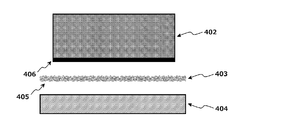
<9> A method for producing a sliding member having a surface layer containing a fluorine resin on a sliding surface,
A surface layer member containing a fluororesin, an intermediate layer member containing a fiber sheet, and a preparation step of preparing a substrate, and one surface of the surface layer member and the intermediate layer member, and the intermediate layer member The manufacturing method of the sliding member characterized by including the thermocompression-bonding process of thermocompression bonding the other surface and the said base material.
<10> The intermediate layer member is a member obtained by impregnating the fiber sheet with a thermoplastic resin other than a fluorine-based resin,
The method for producing a sliding member according to <9>, wherein in the thermocompression bonding step, the fluororesin contained in the surface layer member penetrates into the fiber sheet contained in the intermediate layer member.
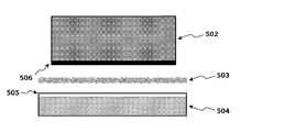
<11> The intermediate layer member is a member in which the fiber sheet is impregnated with a fluororesin, and the base material is a base material coated with a thermoplastic resin other than the fluororesin on the surface,
<9> The method for producing a sliding member according to <9>, wherein in the thermocompression bonding step, a thermoplastic resin other than the fluorine-based resin applied to the base material penetrates into the fiber sheet included in the intermediate layer member.
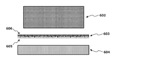
<12> The substrate is a substrate having a surface coated with a thermoplastic resin other than a fluororesin,
In the thermocompression bonding step, a thermoplastic resin other than the fluororesin contained in the surface layer member and the fluororesin applied to the base material penetrates into the fiber sheet contained in the intermediate layer member, <9 The manufacturing method of the sliding member as described in>.
<13> The intermediate layer member is a member obtained by impregnating one surface of the fiber sheet with a fluororesin and the other surface of the fiber sheet with a thermoplastic resin other than the fluororesin,
In the thermocompression bonding step, the surface layer member and the intermediate layer member impregnated with a fluorine resin, and the intermediate layer member impregnated with a thermoplastic resin other than the fluorine resin and the base material The manufacturing method of the sliding member as described in <9> which carries out thermocompression bonding.
<1> 基材と、前記基材上に設けられ、フッ素樹脂を含み、摺動面を有する表面層と、を有する摺動部材であって、
前記表面層と前記基材との間に繊維シートを含む中間層を有し、
前記中間層が、前記繊維シートの表面層側繊維間隙にフッ素系樹脂を、前記繊維シートの基材側繊維間隙にフッ素系樹脂以外の熱可塑性樹脂を含むことを特徴とする摺動部材。
<2>前記表面層に含まれるフッ素系樹脂が、ポリテトラフルオロエチレン(PTFE)、テトラフルオロエチレン・パーフルオロアルキルビニルエーテル共重合体(PFA)、及びテトラフルオロエチレン・ヘキサフルオロプロピレン共重合体(FEP)からなる群より選択される少なくとも1種の樹脂である、<1>に記載の摺動部材。
<3> 前記表面層が、繊維シートを含む層である、<1>又は<2>に記載の摺動部材。
<4> 前記中間層に含まれるフッ素系樹脂が、ポリテトラフルオロエチレン(PTFE)、テトラフルオロエチレン・パーフルオロアルキルビニルエーテル共重合体(PFA)、テトラフルオロエチレン・ヘキサフルオロプロピレン共重合体(FEP)、ポリビニリデンジフルオライド(PVDF)、テトラフルオロエチレン・エチレン共重合体(ETFE)、及びポリクロロトリフルオロエチレン(PCTFE)からなる群より選択される少なくとも1種の樹脂である、<1>~<3>の何れかに記載の摺動部材。
<5> 前記中間層に含まれるフッ素系樹脂以外の熱可塑性樹脂が、ポリエーテルエーテルケトン(PEEK)、ポリフェニレンサルファイド(PPS)、ポリエーテルサルフォン(PES)、ポリイミド(PI)、ポリアミドイミド(PAI)、ポリサルフォン(PSF)、ポリアリレート(PAR)、及びポリエーテルイミド(PEI)からなる群より選択される少なくとも1種の樹脂である、<1>~<4>の何れかに記載の摺動部材。
<6> 前記中間層に含まれる繊維シートが、アラミド樹脂、フッ素系樹脂、ポリアミド系樹脂、ポリエステル系樹脂、アクリル系樹脂、ポリビニルアルコール系樹脂、ポリオレフィン系樹脂、ポリウレタン樹脂、セルロース系樹脂、及びカーボン繊維からなる群より選択される少なくとも1種で構成されたシートである、<1>~<5>の何れかに記載の摺動部材。
<7> 前記基材が、カーボン、セラミックス、及び金属からなる群より選択される少なくとも1種の材料で構成された基材である、<1>~<6>の何れかに記載の摺動部材。
<8><1>~<7>の何れかに記載の摺動部材を備えるメカニカルシール。
<9> 摺動面にフッ素系樹脂を含む表面層を有する摺動部材の製造方法であって、
フッ素系樹脂を含む表面層用部材、繊維シートを含む中間層用部材、及び基材を準備する準備工程、並びに
前記表面層用部材と前記中間層用部材の一面、及び前記中間層用部材の他面と前記基材を熱圧着する熱圧着工程
を含むことを特徴とする摺動部材の製造方法。
<10> 前記中間層用部材が、前記繊維シートにフッ素系樹脂以外の熱可塑性樹脂を含浸した部材であり、
前記熱圧着工程において、前記表面層用部材に含まれるフッ素系樹脂が前記中間層用部材に含まれる繊維シートに浸透する、<9>に記載の摺動部材の製造方法。
<11> 前記中間層用部材が、前記繊維シートにフッ素系樹脂を含浸した部材で、前記基材が、表面にフッ素系樹脂以外の熱可塑性樹脂が塗布された基材であり、
前記熱圧着工程において、前記基材に塗布されたフッ素系樹脂以外の熱可塑性樹脂が前記中間層用部材に含まれる繊維シートに浸透する、<9>に記載の摺動部材の製造方法。
<12> 前記基材が、表面にフッ素系樹脂以外の熱可塑性樹脂が塗布された基材であり、
前記熱圧着工程において、前記表面層用部材に含まれるフッ素系樹脂と前記基材に塗布されたフッ素系樹脂以外の熱可塑性樹脂が前記中間層用部材に含まれる繊維シートに浸透する、<9>に記載の摺動部材の製造方法。
<13> 前記中間層用部材が、前記繊維シートの一面にフッ素系樹脂を、前記繊維シートの他面にフッ素系樹脂以外の熱可塑性樹脂を含浸した部材であり、
前記熱圧着工程において、前記表面層用部材と前記中間層用部材のフッ素系樹脂を含浸した面、及び前記中間層用部材のフッ素系樹脂以外の熱可塑性樹脂を含浸した面と前記基材を熱圧着する、<9>に記載の摺動部材の製造方法。 That is, the present invention is as follows.
<1> A sliding member having a base material and a surface layer provided on the base material, including a fluororesin and having a sliding surface,
Having an intermediate layer comprising a fiber sheet between the surface layer and the substrate;
The sliding member, wherein the intermediate layer includes a fluorine-based resin in a surface layer side fiber gap of the fiber sheet, and a thermoplastic resin other than the fluorine-based resin in a base material side fiber gap of the fiber sheet.
<2> The fluororesin contained in the surface layer is polytetrafluoroethylene (PTFE), tetrafluoroethylene / perfluoroalkyl vinyl ether copolymer (PFA), or tetrafluoroethylene / hexafluoropropylene copolymer (FEP). The sliding member according to <1>, which is at least one resin selected from the group consisting of:
<3> The sliding member according to <1> or <2>, wherein the surface layer is a layer including a fiber sheet.
<4> The fluororesin contained in the intermediate layer is polytetrafluoroethylene (PTFE), tetrafluoroethylene / perfluoroalkyl vinyl ether copolymer (PFA), tetrafluoroethylene / hexafluoropropylene copolymer (FEP). Or at least one resin selected from the group consisting of polyvinylidene difluoride (PVDF), tetrafluoroethylene / ethylene copolymer (ETFE), and polychlorotrifluoroethylene (PCTFE), <1> to <3> The sliding member according to any one of the above.
<5> Thermoplastic resins other than the fluororesin contained in the intermediate layer are polyetheretherketone (PEEK), polyphenylene sulfide (PPS), polyethersulfone (PES), polyimide (PI), polyamideimide (PAI). ), Polysulfone (PSF), polyarylate (PAR), and polyetherimide (PEI), at least one resin selected from the group consisting of sliding according to any one of <1> to <4> Element.
<6> The fiber sheet included in the intermediate layer includes an aramid resin, a fluorine resin, a polyamide resin, a polyester resin, an acrylic resin, a polyvinyl alcohol resin, a polyolefin resin, a polyurethane resin, a cellulose resin, and carbon. The sliding member according to any one of <1> to <5>, which is a sheet composed of at least one selected from the group consisting of fibers.
<7> The sliding material according to any one of <1> to <6>, wherein the base material is a base material made of at least one material selected from the group consisting of carbon, ceramics, and metal. Element.
<8> A mechanical seal provided with the sliding member according to any one of <1> to <7>.
<9> A method for producing a sliding member having a surface layer containing a fluorine resin on a sliding surface,
A surface layer member containing a fluororesin, an intermediate layer member containing a fiber sheet, and a preparation step of preparing a substrate, and one surface of the surface layer member and the intermediate layer member, and the intermediate layer member The manufacturing method of the sliding member characterized by including the thermocompression-bonding process of thermocompression bonding the other surface and the said base material.
<10> The intermediate layer member is a member obtained by impregnating the fiber sheet with a thermoplastic resin other than a fluorine-based resin,
The method for producing a sliding member according to <9>, wherein in the thermocompression bonding step, the fluororesin contained in the surface layer member penetrates into the fiber sheet contained in the intermediate layer member.
<11> The intermediate layer member is a member in which the fiber sheet is impregnated with a fluororesin, and the base material is a base material coated with a thermoplastic resin other than the fluororesin on the surface,
<9> The method for producing a sliding member according to <9>, wherein in the thermocompression bonding step, a thermoplastic resin other than the fluorine-based resin applied to the base material penetrates into the fiber sheet included in the intermediate layer member.
<12> The substrate is a substrate having a surface coated with a thermoplastic resin other than a fluororesin,
In the thermocompression bonding step, a thermoplastic resin other than the fluororesin contained in the surface layer member and the fluororesin applied to the base material penetrates into the fiber sheet contained in the intermediate layer member, <9 The manufacturing method of the sliding member as described in>.
<13> The intermediate layer member is a member obtained by impregnating one surface of the fiber sheet with a fluororesin and the other surface of the fiber sheet with a thermoplastic resin other than the fluororesin,
In the thermocompression bonding step, the surface layer member and the intermediate layer member impregnated with a fluorine resin, and the intermediate layer member impregnated with a thermoplastic resin other than the fluorine resin and the base material The manufacturing method of the sliding member as described in <9> which carries out thermocompression bonding.
本発明によれば、摺動面に形成される表面層が剥離し難い摺動部材を提供することができる。
According to the present invention, it is possible to provide a sliding member in which the surface layer formed on the sliding surface is difficult to peel off.
<摺動部材>
本発明の一態様である摺動部材(以下、「本発明の摺動部材」と略す場合がある。)は、基材と、前記基材上に設けられ、フッ素樹脂を含み、摺動面を有する表面層と、を有する摺動部材である。そして、表面層と基材との間に繊維シートを含む中間層を有し、さらに中間層が、繊維シートの表面層側繊維間隙にフッ素系樹脂を、繊維シートの基材側繊維間隙にフッ素系樹脂以外の熱可塑性樹脂を含むことを特徴とする。
前述のように、メカニカルシール等の摺動部材の摺動面に樹脂コーディング層や繊維質摺動材を設けることがあるが、過酷な条件や長期間の使用等により、このような層が基材から剥離してしまうことがあった。本発明者らは、表面層と基材との間に上記のような特殊な中間層を設けることにより、表面層が剥離し難くなることを見出したのである。
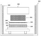
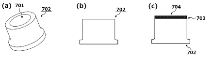
図1(a)は、本発明の摺動部材(一実施形態)の摺動面付近の断面を表した模式図である。摺動部材101は、基材102の表面上に中間層103と表面層104が積層させた構造となっており、中間層103の内部には繊維シート105が含まれ、さらに繊維シート105の表面層側繊維間隙にフッ素系樹脂106が、繊維シート105の基材側繊維間隙にフッ素系樹脂以外の熱可塑性樹脂107が含まれた構造となっている。表面層104との密着性が高いフッ素系樹脂106と、基材102との密着性が高いフッ素系樹脂以外の熱可塑性樹脂107のそれぞれが、繊維シート105の細孔や凹凸に入り込んだ構造となっており、いわゆる「アンカー効果」を発揮して、表面層104-中間層103間の接着強度、及び中間層103-基材102間の接着強度が向上し、表面層が剥離し難くなるのである。
なお、表面層が中間層に含まれるフッ素系樹脂と同種の樹脂のみからなる場合、図1(b)に示されるように表面層104と中間層103の境界が明確に表れない場合もあるが、このような実施形態であっても、繊維シート105の表面層側繊維間隙にフッ素系樹脂を含んでいることになるため、本発明の範囲に含まれるものと言える。
また、図1(c)や(d)に示されるように、繊維シート105が溶融して、表面層104やフッ素樹脂106と一体化してしまっている実施形態も本発明の範囲に含まれる。
ここで、本発明において「繊維シート」とは、複数の繊維を束ねてシート状に加工した材料を意味するものとする。
以下、「表面層」、「中間層」、「基材」等について詳細に説明する。 <Sliding member>
A sliding member which is one embodiment of the present invention (hereinafter sometimes abbreviated as “sliding member of the present invention”) is provided on a base material, the base material, contains a fluororesin, and has a sliding surface. And a surface layer having a sliding member. An intermediate layer including a fiber sheet is provided between the surface layer and the substrate, and the intermediate layer further includes a fluorine-based resin in the surface layer side fiber gap of the fiber sheet, and a fluorine in the substrate side fiber gap of the fiber sheet. It includes a thermoplastic resin other than the base resin.
As described above, a resin coding layer or a fibrous sliding material may be provided on the sliding surface of a sliding member such as a mechanical seal. However, such a layer may be used due to severe conditions or long-term use. The material sometimes peeled off. The present inventors have found that the surface layer is difficult to peel by providing the above-described special intermediate layer between the surface layer and the substrate.
FIG. 1A is a schematic diagram showing a cross section near the sliding surface of the sliding member (one embodiment) of the present invention. The slidingmember 101 has a structure in which an intermediate layer 103 and a surface layer 104 are laminated on the surface of the base material 102. The intermediate layer 103 includes a fiber sheet 105, and further the surface of the fiber sheet 105. The layer-side fiber gap includes a fluorine-based resin 106, and the base-material-side fiber gap of the fiber sheet 105 includes a thermoplastic resin 107 other than the fluorine-based resin. Each of the fluorine resin 106 having high adhesion to the surface layer 104 and the thermoplastic resin 107 other than the fluorine resin having high adhesion to the base material 102 enters the pores and irregularities of the fiber sheet 105, and Since the so-called “anchor effect” is exhibited, the adhesive strength between the surface layer 104 and the intermediate layer 103 and the adhesive strength between the intermediate layer 103 and the base material 102 are improved, and the surface layer becomes difficult to peel off. is there.
When the surface layer is made of only the same type of resin as the fluororesin contained in the intermediate layer, the boundary between thesurface layer 104 and the intermediate layer 103 may not be clearly shown as shown in FIG. Even in such an embodiment, it can be said that the surface layer side fiber gap of the fiber sheet 105 contains a fluorine-based resin, and thus is included in the scope of the present invention.
In addition, as shown in FIGS. 1C and 1D, an embodiment in which thefiber sheet 105 is melted and integrated with the surface layer 104 and the fluororesin 106 is also included in the scope of the present invention.
Here, in the present invention, the “fiber sheet” means a material obtained by bundling a plurality of fibers and processing the sheet.
Hereinafter, the “surface layer”, “intermediate layer”, “base material” and the like will be described in detail.
本発明の一態様である摺動部材(以下、「本発明の摺動部材」と略す場合がある。)は、基材と、前記基材上に設けられ、フッ素樹脂を含み、摺動面を有する表面層と、を有する摺動部材である。そして、表面層と基材との間に繊維シートを含む中間層を有し、さらに中間層が、繊維シートの表面層側繊維間隙にフッ素系樹脂を、繊維シートの基材側繊維間隙にフッ素系樹脂以外の熱可塑性樹脂を含むことを特徴とする。
前述のように、メカニカルシール等の摺動部材の摺動面に樹脂コーディング層や繊維質摺動材を設けることがあるが、過酷な条件や長期間の使用等により、このような層が基材から剥離してしまうことがあった。本発明者らは、表面層と基材との間に上記のような特殊な中間層を設けることにより、表面層が剥離し難くなることを見出したのである。
図1(a)は、本発明の摺動部材(一実施形態)の摺動面付近の断面を表した模式図である。摺動部材101は、基材102の表面上に中間層103と表面層104が積層させた構造となっており、中間層103の内部には繊維シート105が含まれ、さらに繊維シート105の表面層側繊維間隙にフッ素系樹脂106が、繊維シート105の基材側繊維間隙にフッ素系樹脂以外の熱可塑性樹脂107が含まれた構造となっている。表面層104との密着性が高いフッ素系樹脂106と、基材102との密着性が高いフッ素系樹脂以外の熱可塑性樹脂107のそれぞれが、繊維シート105の細孔や凹凸に入り込んだ構造となっており、いわゆる「アンカー効果」を発揮して、表面層104-中間層103間の接着強度、及び中間層103-基材102間の接着強度が向上し、表面層が剥離し難くなるのである。
なお、表面層が中間層に含まれるフッ素系樹脂と同種の樹脂のみからなる場合、図1(b)に示されるように表面層104と中間層103の境界が明確に表れない場合もあるが、このような実施形態であっても、繊維シート105の表面層側繊維間隙にフッ素系樹脂を含んでいることになるため、本発明の範囲に含まれるものと言える。
また、図1(c)や(d)に示されるように、繊維シート105が溶融して、表面層104やフッ素樹脂106と一体化してしまっている実施形態も本発明の範囲に含まれる。
ここで、本発明において「繊維シート」とは、複数の繊維を束ねてシート状に加工した材料を意味するものとする。
以下、「表面層」、「中間層」、「基材」等について詳細に説明する。 <Sliding member>
A sliding member which is one embodiment of the present invention (hereinafter sometimes abbreviated as “sliding member of the present invention”) is provided on a base material, the base material, contains a fluororesin, and has a sliding surface. And a surface layer having a sliding member. An intermediate layer including a fiber sheet is provided between the surface layer and the substrate, and the intermediate layer further includes a fluorine-based resin in the surface layer side fiber gap of the fiber sheet, and a fluorine in the substrate side fiber gap of the fiber sheet. It includes a thermoplastic resin other than the base resin.
As described above, a resin coding layer or a fibrous sliding material may be provided on the sliding surface of a sliding member such as a mechanical seal. However, such a layer may be used due to severe conditions or long-term use. The material sometimes peeled off. The present inventors have found that the surface layer is difficult to peel by providing the above-described special intermediate layer between the surface layer and the substrate.
FIG. 1A is a schematic diagram showing a cross section near the sliding surface of the sliding member (one embodiment) of the present invention. The sliding
When the surface layer is made of only the same type of resin as the fluororesin contained in the intermediate layer, the boundary between the
In addition, as shown in FIGS. 1C and 1D, an embodiment in which the
Here, in the present invention, the “fiber sheet” means a material obtained by bundling a plurality of fibers and processing the sheet.
Hereinafter, the “surface layer”, “intermediate layer”, “base material” and the like will be described in detail.
(表面層)
本発明の摺動部材は、摺動面にフッ素系樹脂(以下、「表面層のフッ素系樹脂」と略す場合がある。)を含む表面層を有するものであるが、表面層のフッ素系樹脂の種類や含有量、フッ素系樹脂以外の成分、厚み等は特に限定されず、公知の技術内容を適宜採用することができる。以下、具体例を挙げて説明する。
表面層のフッ素系樹脂は、フッ素原子を含む高分子化合物であれば特に限定されないが、ポリテトラフルオロエチレン(PTFE)、テトラフルオロエチレン・パーフルオロアルキルビニルエーテル共重合体(PFA)、テトラフルオロエチレン・ヘキサフルオロプロピレン共重合体(FEP)、ポリビニリデンジフルオライド(PVDF)、テトラフルオロエチレン・エチレン共重合体(ETFE)、ポリクロロトリフルオロエチレン(PCTFE)等が挙げられる。この中でもポリテトラフルオロエチレン(PTFE)、テトラフルオロエチレン・パーフルオロアルキルビニルエーテル共重合体(PFA)、テトラフルオロエチレン・ヘキサフルオロプロピレン共重合体(FEP)が好ましく、ポリテトラフルオロエチレン(PTFE)、テトラフルオロエチレン・パーフルオロアルキルビニルエーテル共重合体(PFA)が特に好ましい。上記のようなフッ素系樹脂であると、摩耗や摩擦を低減し易くなる。なお、表面層のフッ素系樹脂は、1種類に限られず、2種類以上の組合せであってもよい。 (Surface layer)
The sliding member of the present invention has a surface layer containing a fluorine-based resin (hereinafter sometimes abbreviated as “surface-layer fluorine-based resin”) on the sliding surface. There are no particular restrictions on the type, content, components other than the fluororesin, thickness, and the like, and known technical contents can be employed as appropriate. Hereinafter, a specific example will be described.
The fluororesin of the surface layer is not particularly limited as long as it is a polymer compound containing fluorine atoms, but polytetrafluoroethylene (PTFE), tetrafluoroethylene / perfluoroalkyl vinyl ether copolymer (PFA), tetrafluoroethylene / Examples include hexafluoropropylene copolymer (FEP), polyvinylidene difluoride (PVDF), tetrafluoroethylene / ethylene copolymer (ETFE), and polychlorotrifluoroethylene (PCTFE). Among these, polytetrafluoroethylene (PTFE), tetrafluoroethylene / perfluoroalkyl vinyl ether copolymer (PFA), and tetrafluoroethylene / hexafluoropropylene copolymer (FEP) are preferable, and polytetrafluoroethylene (PTFE), tetra A fluoroethylene / perfluoroalkyl vinyl ether copolymer (PFA) is particularly preferred. When the fluororesin is as described above, it is easy to reduce wear and friction. In addition, the fluorine resin of the surface layer is not limited to one type, and may be a combination of two or more types.
表面層のフッ素系樹脂の含有量(2種類以上の場合には総含有量)は、通常30質量%以上、好ましくは40質量%以上、より好ましくは50質量%以上であり、通常100質量%以下、好ましくは95質量%以下、より好ましくは90質量%以下である。上記範囲内であると、摩耗や摩擦を低減し易くなる。
The content (in the case of two or more types) of the fluororesin in the surface layer is usually 30% by mass or more, preferably 40% by mass or more, more preferably 50% by mass or more, and usually 100% by mass. Hereinafter, it is preferably 95% by mass or less, more preferably 90% by mass or less. Within the above range, it is easy to reduce wear and friction.
表面層は、繊維シート(以下、「表面層の繊維シート」と略す場合がある。)を含む層であることが好ましい。図2は、本発明の摺動部材(一実施形態)の摺動面付近の断面を表した模式図であるが、中間層203のみならず、表面層204にも繊維シート208が含まれた構造となっている。表面層にこのような繊維シートが含まれると、摩耗や摩擦をより低減し易くなるのである。
表面層の繊維シートは、中間層の繊維シートと同様に複数の繊維を束ねてシート状に加工した材料を意味し、その材質、厚み等は特に限定されず、公知の技術内容を適宜採用することができる。以下、具体例を挙げて説明する。
表面層の繊維シートの材質としては、アラミド、PTFE等の樹脂繊維、炭素繊維(カーボン繊維になる前の前駆体繊維を含む)、ガラス繊維、金属繊維等中間層に用いるフッ素樹脂よりも融点の高い材料が挙げられる。この中でも、樹脂繊維が好ましく、具体的にはアラミド、PTFEが好ましく、PTFEが特に好ましい。上記のような材料であると、摩耗や摩擦を低減し易くなる。なお、表面層の繊維シートは、1種類の材料で構成されたものに限られず、2種類以上の材料で構成されたものであってもよい。 The surface layer is preferably a layer containing a fiber sheet (hereinafter sometimes abbreviated as “fiber sheet of surface layer”). FIG. 2 is a schematic view showing a cross section near the sliding surface of the sliding member (one embodiment) of the present invention, and the fiber layer 208 is included not only in theintermediate layer 203 but also in the surface layer 204. It has a structure. When such a fiber sheet is contained in the surface layer, it becomes easier to reduce wear and friction.
The fiber sheet of the surface layer means a material obtained by bundling a plurality of fibers and processing into a sheet shape like the fiber sheet of the intermediate layer, and the material, thickness and the like are not particularly limited, and well-known technical contents are appropriately adopted. be able to. Hereinafter, a specific example will be described.
As the material for the fiber sheet of the surface layer, the melting point is higher than that of the fluororesin used for the intermediate layer such as resin fibers such as aramid and PTFE, carbon fibers (including precursor fibers before becoming carbon fibers), glass fibers and metal fibers. High materials are mentioned. Among these, resin fibers are preferable, specifically, aramid and PTFE are preferable, and PTFE is particularly preferable. When the material is as described above, it is easy to reduce wear and friction. In addition, the fiber sheet of the surface layer is not limited to one made of one kind of material, and may be made of two or more kinds of materials.
表面層の繊維シートは、中間層の繊維シートと同様に複数の繊維を束ねてシート状に加工した材料を意味し、その材質、厚み等は特に限定されず、公知の技術内容を適宜採用することができる。以下、具体例を挙げて説明する。
表面層の繊維シートの材質としては、アラミド、PTFE等の樹脂繊維、炭素繊維(カーボン繊維になる前の前駆体繊維を含む)、ガラス繊維、金属繊維等中間層に用いるフッ素樹脂よりも融点の高い材料が挙げられる。この中でも、樹脂繊維が好ましく、具体的にはアラミド、PTFEが好ましく、PTFEが特に好ましい。上記のような材料であると、摩耗や摩擦を低減し易くなる。なお、表面層の繊維シートは、1種類の材料で構成されたものに限られず、2種類以上の材料で構成されたものであってもよい。 The surface layer is preferably a layer containing a fiber sheet (hereinafter sometimes abbreviated as “fiber sheet of surface layer”). FIG. 2 is a schematic view showing a cross section near the sliding surface of the sliding member (one embodiment) of the present invention, and the fiber layer 208 is included not only in the
The fiber sheet of the surface layer means a material obtained by bundling a plurality of fibers and processing into a sheet shape like the fiber sheet of the intermediate layer, and the material, thickness and the like are not particularly limited, and well-known technical contents are appropriately adopted. be able to. Hereinafter, a specific example will be described.
As the material for the fiber sheet of the surface layer, the melting point is higher than that of the fluororesin used for the intermediate layer such as resin fibers such as aramid and PTFE, carbon fibers (including precursor fibers before becoming carbon fibers), glass fibers and metal fibers. High materials are mentioned. Among these, resin fibers are preferable, specifically, aramid and PTFE are preferable, and PTFE is particularly preferable. When the material is as described above, it is easy to reduce wear and friction. In addition, the fiber sheet of the surface layer is not limited to one made of one kind of material, and may be made of two or more kinds of materials.
表面層の繊維シートの厚み(フッ素系樹脂等を含む前の厚み)は、通常0.3mm以上、好ましくは0.5mm以上、より好ましくは0.8m以上であり、通常2.0mm以下、好ましくは1.5mm以下、より好ましくは1.2m以下である。上記範囲内であると、摩耗や摩擦を低減し易くなる。上記は、複数枚を重ねて上記範囲の厚さとしてもよい。
The thickness of the fiber sheet of the surface layer (the thickness before including the fluororesin) is usually 0.3 mm or more, preferably 0.5 mm or more, more preferably 0.8 m or more, and usually 2.0 mm or less, preferably Is 1.5 mm or less, more preferably 1.2 m or less. Within the above range, it is easy to reduce wear and friction. In the above, a plurality of sheets may be stacked to have a thickness in the above range.
表面層の繊維シートの最大孔径(フッ素系樹脂等を含む前の最大孔径)は、フッ素系樹脂等の粒子を含浸させ易い大きさであることが好ましいが、通常0.005mm以上、好ましくは0.010mm以上、より好ましくは0.05mm以上であり、通常0.5mm以下、好ましくは0.3mm以下、より好ましくは0.2mm以下である。上記範囲内であると、摩耗や摩擦を低減し易くなる。
The maximum pore size of the fiber sheet of the surface layer (maximum pore size before including the fluorine-based resin or the like) is preferably such a size that the particles such as the fluorine-based resin can be easily impregnated, but is usually 0.005 mm or more, preferably 0. 0.010 mm or more, more preferably 0.05 mm or more, and usually 0.5 mm or less, preferably 0.3 mm or less, more preferably 0.2 mm or less. Within the above range, it is easy to reduce wear and friction.
表面層の繊維シートの空隙率(フッ素系樹脂等を含む前の空隙率)は、フッ素系樹脂等の粒子を十分に含浸させ易い比率であることが好ましいが、通常50%以上、好ましくは60%以上、より好ましくは70%以上であり、通常98%以下、好ましくは97%以下、より好ましくは95%以下である。上記範囲内であると、摩耗や摩擦を低減し易くなる。
The porosity of the fiber sheet of the surface layer (the porosity before including the fluororesin etc.) is preferably such a ratio that the particles such as the fluororesin can be sufficiently impregnated, but usually 50% or more, preferably 60 % Or more, more preferably 70% or more, and usually 98% or less, preferably 97% or less, more preferably 95% or less. Within the above range, it is easy to reduce wear and friction.
表面層の厚みは、通常0.3mm以上、好ましくは0.5mm以上、より好ましくは0.8mm以上であり、通常2.0mm以下、好ましくは1.5mm以下、より好ましくは1.2mm以下である。上記範囲内であると、摩耗や摩擦を低減し易くなる。
The thickness of the surface layer is usually 0.3 mm or more, preferably 0.5 mm or more, more preferably 0.8 mm or more, and usually 2.0 mm or less, preferably 1.5 mm or less, more preferably 1.2 mm or less. is there. Within the above range, it is easy to reduce wear and friction.
(中間層)
本発明の摺動部材は、表面層と基材との間に繊維シート(以下、「中間層の繊維シート」と略す場合がある。)を含む中間層を有し、さらに中間層が、繊維シートの表面層側表面と繊維シートの繊維間隙にフッ素系樹脂(以下、「中間層のフッ素系樹脂」と略す場合がある。)を、繊維シートの基材側表面と繊維シートの繊維間隙にフッ素系樹脂以外の熱可塑性樹脂(フッ素樹脂よりも基材との密着性が高い樹脂材)を含むことを特徴とするが、繊維シートの材質や厚み、フッ素系樹脂の種類や含有量、フッ素系樹脂以外の熱可塑性樹脂の種類や含有量等は特に限定されず、公知の技術内容を適宜採用することができる。以下、具体例を挙げて説明する。
中間層の繊維シートの材質としては、ポリテトラフルオロエチレン等の樹脂繊維、炭素繊維、ガラス繊維、金属繊維等が挙げられる。この中でも、樹脂繊維が好ましく、具体的にはフッ素系樹脂、ポリアミド系樹脂、アラミド樹脂等がより好ましく、ポリテトラフルオロエチレン(PTFE)等のフッ素系樹脂が特に好ましい。
また、中間層の繊維シートの融点としては、通常200℃以上、好ましくは260℃以上、より好ましくは320℃以上であり、通常500℃以下、好ましくは400℃以下、より好ましくは390℃以下であり、溶融した場合に流出し難い特性が不可欠である。
上記のような中間層の材料であると、アンカー効果を十分に発揮して、表面層をより剥離し難くすることができる。なお、中間層の繊維シートは、1種類の材料で構成されたものに限られず、2種類以上の材料で構成されたものであってもよい。 (Middle layer)
The sliding member of the present invention has an intermediate layer including a fiber sheet (hereinafter sometimes abbreviated as “fiber sheet of intermediate layer”) between the surface layer and the base material, and the intermediate layer further includes a fiber. A fluorine-based resin (hereinafter sometimes abbreviated as “fluorine-based resin of the intermediate layer”) is provided between the surface layer side surface of the sheet and the fiber sheet and the fiber gap between the fiber sheet and the substrate side surface of the fiber sheet. It contains a thermoplastic resin other than fluororesin (resin material with higher adhesion to the base material than fluororesin), but the material and thickness of the fiber sheet, the type and content of fluororesin, fluorine The type and content of the thermoplastic resin other than the base resin are not particularly limited, and known technical contents can be appropriately employed. Hereinafter, a specific example will be described.
Examples of the material for the fiber sheet of the intermediate layer include resin fibers such as polytetrafluoroethylene, carbon fibers, glass fibers, and metal fibers. Among these, resin fibers are preferable, specifically, fluorine resins, polyamide resins, and aramid resins are more preferable, and fluorine resins such as polytetrafluoroethylene (PTFE) are particularly preferable.
The melting point of the fiber sheet of the intermediate layer is usually 200 ° C. or higher, preferably 260 ° C. or higher, more preferably 320 ° C. or higher, and usually 500 ° C. or lower, preferably 400 ° C. or lower, more preferably 390 ° C. or lower. It is essential to have the property of not easily flowing out when melted.
When the material for the intermediate layer is as described above, the anchor effect can be sufficiently exhibited and the surface layer can be made more difficult to peel. In addition, the fiber sheet of an intermediate | middle layer is not restricted to what was comprised by one type of material, and may be comprised by 2 or more types of materials.
中間層の繊維シートの厚み(フッ素系樹脂等を含む前の厚み)は、通常0.1mm以上、好ましくは0.15mm以上、より好ましくは0.2mm以上であり、通常1.2mm以下、好ましくは1.0mm以下、より好ましくは0.5mm以下である。上記範囲内であると、アンカー効果を十分に発揮して、表面層をより剥離し難くすることができる。
The thickness of the fiber sheet of the intermediate layer (the thickness before including the fluorine-based resin) is usually 0.1 mm or more, preferably 0.15 mm or more, more preferably 0.2 mm or more, and usually 1.2 mm or less, preferably Is 1.0 mm or less, more preferably 0.5 mm or less. Within the above range, the anchor effect can be sufficiently exerted to make the surface layer more difficult to peel.
中間層の繊維シートの最大孔径(フッ素系樹脂等を含む前の最大孔径)は、フッ素系樹脂等の粒子を含浸させ易い大きさであることが好ましいが、通常0.005mm以上、好ましくは0.010mm以上、より好ましくは0.05mm以上であり、通常0.5mm以下、好ましくは0.3mm以下、より好ましくは0.2mm以下である。上記範囲内であると、アンカー効果を十分に発揮して、表面層をより剥離し難くすることができる。
The maximum pore size of the intermediate layer fiber sheet (maximum pore size before including the fluorine-based resin or the like) is preferably such a size that the particles such as the fluorine-based resin can be easily impregnated, but is usually 0.005 mm or more, preferably 0. 0.010 mm or more, more preferably 0.05 mm or more, and usually 0.5 mm or less, preferably 0.3 mm or less, more preferably 0.2 mm or less. Within the above range, the anchor effect can be sufficiently exerted to make the surface layer more difficult to peel.
中間層の繊維シートの空隙率(フッ素系樹脂等を含む前の空隙率)は、通常50%以上、好ましくは60%以上、より好ましくは70%以上であり、フッ素系樹脂等の粒子を十分に含浸させ易い比率であることが好ましいが、通常98%以下、好ましくは97%以下、より好ましくは95%以下である。上記範囲内であると、アンカー効果を十分に発揮して、表面層をより剥離し難くすることができる。
The porosity of the fiber sheet of the intermediate layer (the porosity before including the fluororesin etc.) is usually 50% or more, preferably 60% or more, more preferably 70% or more. However, it is usually 98% or less, preferably 97% or less, more preferably 95% or less. Within the above range, the anchor effect can be sufficiently exerted to make the surface layer more difficult to peel.
中間層のフッ素系樹脂は、表面層と同様にフッ素原子を含む高分子化合物であれば特に限定されないが、表面層のフッ素系樹脂と同様の性質を有することが好ましい。具体的には、ポリテトラフルオロエチレン(PTFE)、テトラフルオロエチレン・パーフルオロアルキルビニルエーテル共重合体(PFA)、テトラフルオロエチレン・ヘキサフルオロプロピレン共重合体(FEP)、ポリビニリデンジフルオライド(PVDF)、テトラフルオロエチレン・エチレン共重合体(ETFE)、ポリクロロトリフルオロエチレン(PCTFE)等が挙げられる。この中でもポリテトラフルオロエチレン(PTFE)、テトラフルオロエチレン・パーフルオロアルキルビニルエーテル共重合体(PFA)、テトラフルオロエチレン・ヘキサフルオロプロピレン共重合体(FEP)が好ましく、ポリテトラフルオロエチレン(PTFE)、テトラフルオロエチレン・パーフルオロアルキルビニルエーテル共重合体(PFA)が特に好ましい。
また、中間層のフッ素系樹脂の融点としては、通常200℃以上、好ましくは260℃以上、より好ましくは320℃以上であり、通常500℃以下、好ましくは400℃以下、より好ましくは390℃以下である。
上記のようなフッ素系樹脂であると、アンカー効果を十分に発揮して、表面層をより剥離し難くすることができる。なお、中間層のフッ素系樹脂は、1種類に限られず、2種類以上の組合せであってもよい。 The fluororesin of the intermediate layer is not particularly limited as long as it is a polymer compound containing fluorine atoms as in the surface layer, but preferably has the same properties as the fluororesin of the surface layer. Specifically, polytetrafluoroethylene (PTFE), tetrafluoroethylene / perfluoroalkyl vinyl ether copolymer (PFA), tetrafluoroethylene / hexafluoropropylene copolymer (FEP), polyvinylidene difluoride (PVDF) , Tetrafluoroethylene / ethylene copolymer (ETFE), polychlorotrifluoroethylene (PCTFE), and the like. Among these, polytetrafluoroethylene (PTFE), tetrafluoroethylene / perfluoroalkyl vinyl ether copolymer (PFA), and tetrafluoroethylene / hexafluoropropylene copolymer (FEP) are preferable, and polytetrafluoroethylene (PTFE), tetra A fluoroethylene / perfluoroalkyl vinyl ether copolymer (PFA) is particularly preferred.
The melting point of the fluororesin of the intermediate layer is usually 200 ° C. or higher, preferably 260 ° C. or higher, more preferably 320 ° C. or higher, and usually 500 ° C. or lower, preferably 400 ° C. or lower, more preferably 390 ° C. or lower. It is.
When the fluororesin is as described above, the anchor effect can be sufficiently exerted and the surface layer can be made more difficult to peel. In addition, the fluororesin of the intermediate layer is not limited to one type, and may be a combination of two or more types.
フッ素系樹脂以外の熱可塑性樹脂は、フッ素系樹脂以外の熱可塑性樹脂であれば特に限定されないが、オレフィン系樹脂、スチレン系樹脂、アクリル系樹脂、ポリエステル系樹脂、ポリカーボネート系樹脂、が挙げられる。この中でも、スーパーエンジニアリングプラスチックが好ましく、具体的にはポリエーテルエーテルケトン(PEEK)、ポリフェニレンサルファイド(PPS)、ポリエーテルサルフォン(PES)、ポリアミドイミド(PAI)、ポリサルフォン(PSF)、ポリアリレート(PAR)、ポリエーテルイミド(PEI)、等が特に好ましい。
また、フッ素系樹脂以外の熱可塑性樹脂の融点としては、通常200℃以上、好ましくは260℃以上、より好ましくは320℃以上であり、通常500℃以下、好ましくは400℃以下、より好ましくは390℃以下である。
上記のようなフッ素系樹脂以外の熱可塑性樹脂であると、アンカー効果を十分に発揮して、表面層をより剥離し難くすることができる。 The thermoplastic resin other than the fluorine-based resin is not particularly limited as long as it is a thermoplastic resin other than the fluorine-based resin, and examples thereof include olefin resins, styrene resins, acrylic resins, polyester resins, and polycarbonate resins. Among these, super engineering plastics are preferable, and specifically, polyetheretherketone (PEEK), polyphenylene sulfide (PPS), polyethersulfone (PES), polyamideimide (PAI), polysulfone (PSF), polyarylate (PAR). ), Polyetherimide (PEI), and the like are particularly preferable.
The melting point of the thermoplastic resin other than the fluororesin is usually 200 ° C. or higher, preferably 260 ° C. or higher, more preferably 320 ° C. or higher, and usually 500 ° C. or lower, preferably 400 ° C. or lower, more preferably 390. It is below ℃.
When the thermoplastic resin other than the fluorine resin as described above is used, the anchor effect can be sufficiently exhibited and the surface layer can be made more difficult to peel.
フッ素系樹脂とフッ素系樹脂以外の熱可塑性樹脂の組合せとしては、ポリテトラフルオロエチレン(PTFE)とポリエーテルエーテルケトン(PEEK)、テトラフルオロエチレン・パーフルオロアルキルビニルエーテル共重合体(PFA)とポリエーテルエーテルケトン(PEEK)が好ましい。上記のような組合せであると、アンカー効果を十分に発揮して、表面層をより剥離し難くすることができる。
Examples of combinations of fluororesins and thermoplastic resins other than fluororesins include polytetrafluoroethylene (PTFE) and polyether ether ketone (PEEK), tetrafluoroethylene / perfluoroalkyl vinyl ether copolymer (PFA) and polyether. Ether ketone (PEEK) is preferred. When the combination is as described above, the anchor effect can be sufficiently exhibited and the surface layer can be made more difficult to peel.
中間層に含まれるフッ素系樹脂とフッ素系樹脂以外の熱可塑性樹脂の比率(体積換算)は、通常10:90~90:10、好ましくは30:70~70:30、より好ましくは60:40~40:60である。上記範囲内であると、表面層をより剥離し難くすることができる。
The ratio (in terms of volume) of the fluororesin and the thermoplastic resin other than the fluororesin contained in the intermediate layer is usually 10:90 to 90:10, preferably 30:70 to 70:30, more preferably 60:40. ~ 40: 60. Within the above range, the surface layer can be made more difficult to peel.
(基材)
本発明の摺動部材の基材の材質は、特に限定されず、公知の技術内容を適宜採用することができるが、カーボン、炭化ケイ素、炭化タングステン、その他、セラミックス、金属等が挙げられる。なお、基材は、1種類の材料で構成されたものに限られず、2種類以上の材料で構成されたものであってもよい。 (Base material)
The material of the base material of the sliding member of the present invention is not particularly limited, and well-known technical contents can be adopted as appropriate, and examples thereof include carbon, silicon carbide, tungsten carbide, ceramics, metal, and the like. The base material is not limited to one made of one type of material and may be made of two or more types of material.
<メカニカルシール>
本発明の摺動部材の用途は、特に限定されず、メカニカルシール、軸受等の回転機器のシール部材等として利用することが挙げられるが、特にメカニカルシールとして利用することが好ましい。なお、本発明の摺動部材を備えるメカニカルシールも本発明の一態様である(以下、「本発明のメカニカルシール」と略す場合がある。)。
本発明のメカニカルシールの用途も特に限定されないが、多機能濾過乾燥機、真空乾燥機、ロータリーフィーダー、ロータリージョイン等の乾燥潤滑条件での使用される機器に使用されることが特に好ましい。 <Mechanical seal>
The use of the sliding member of the present invention is not particularly limited, and may be used as a sealing member of a rotating device such as a mechanical seal or a bearing, but is particularly preferably used as a mechanical seal. In addition, a mechanical seal provided with the sliding member of the present invention is also an embodiment of the present invention (hereinafter may be abbreviated as “mechanical seal of the present invention”).
Although the use of the mechanical seal of the present invention is not particularly limited, it is particularly preferably used for equipment used under dry lubrication conditions such as a multifunction filter dryer, a vacuum dryer, a rotary feeder, and a rotary join.
<摺動部材の製造方法>
本発明の摺動部材は、フッ素系樹脂を含む表面層用部材、繊維シートを含む中間層用部材、及び基材をそれぞれ準備し、表面層用部材と中間層用部材の一面、及び中間層用部材の他面と基材をそれぞれ熱圧着して製造することが特に好ましい。上記のような製造方法であると、表面層が剥離し難い摺動部材を効率良く製造することができる。
なお、フッ素系樹脂を含む表面層用部材、繊維シートを含む中間層用部材、及び基材を準備する準備工程(以下、「準備工程」と略す場合がある。)、並びに表面層用部材と中間層用部材の一面、及び中間層用部材の他面と基材をそれぞれ熱圧着する熱圧着工程(以下、「熱圧着工程」と略す場合がある。)を含むことを特徴とする摺動部材の製造方法も本発明の一態様である(以下、「本発明の製造方法」と略す場合がある。)。
ここで、「一面」とは、繊維シートや中間層用部材の一方の面を意味し、「他面」とは、その反対側の面を意味するものとする。
以下、本発明の製造方法の好ましい実施形態について詳細に説明する。 <Sliding member manufacturing method>
The sliding member of the present invention includes a surface layer member containing a fluororesin, an intermediate layer member containing a fiber sheet, and a substrate, respectively, and one surface of the surface layer member and the intermediate layer member. It is particularly preferable to manufacture the other side of the member for use and the base material by thermocompression bonding. With the manufacturing method as described above, it is possible to efficiently manufacture a sliding member in which the surface layer is hardly peeled off.
In addition, the member for surface layers containing a fluororesin, the member for intermediate | middle layers containing a fiber sheet, and the preparation process (henceforth abbreviated as "preparation process") which prepares a base material, and the member for surface layers Sliding including a thermocompression process (hereinafter, may be abbreviated as “thermocompression process”) in which one surface of the intermediate layer member and the other surface of the intermediate layer member and the base material are thermocompression bonded. The method for producing a member is also an embodiment of the present invention (hereinafter, sometimes referred to as “the production method of the present invention”).
Here, “one side” means one side of the fiber sheet or the intermediate layer member, and “other side” means the opposite side.
Hereinafter, preferred embodiments of the production method of the present invention will be described in detail.
図3は、本発明の製造方法(一実施形態)の熱圧着工程を表した模式図である。電気炉301内に表面層用部材304、中間層用部材303、基材302、重り308の順に積み重ねられ、重り308の重さによって熱圧着の圧力を設定する仕組みとなっている。
準備された表面層用部材304には、フッ素系樹脂が含まれており(なお、図3の実施形態では、表面層用部材304の中間層用部材側表面にフッ素系樹脂305が塗布されている。)、このフッ素系樹脂の融点以上の加熱条件で熱圧着することによって、フッ素系樹脂が溶融して中間層用部材303の繊維シートに浸透し、形成される中間層は繊維シートの表面層側表面と繊維間隙にフッ素系樹脂を含むことになるのである。一方、準備された中間層用部材303には、フッ素系樹脂以外の熱可塑性樹脂306が含浸されており、形成される中間層は繊維シートの基材側表面と繊維間隙にフッ素系樹脂以外の熱可塑性樹脂を含むことになるのである。 FIG. 3 is a schematic diagram showing a thermocompression bonding step of the manufacturing method (one embodiment) of the present invention. Asurface layer member 304, an intermediate layer member 303, a base material 302, and a weight 308 are stacked in this order in the electric furnace 301, and the thermocompression pressure is set according to the weight of the weight 308.
The preparedsurface layer member 304 contains a fluorine-based resin (in the embodiment shown in FIG. 3, the surface layer member 304 is coated with the fluorine-based resin 305 on the intermediate layer member side surface. ), By thermocompression bonding under heating conditions higher than the melting point of the fluororesin, the fluororesin melts and penetrates into the fiber sheet of the intermediate layer member 303, and the formed intermediate layer is the surface of the fiber sheet. The fluorine resin is included in the layer side surface and the fiber gap. On the other hand, the prepared intermediate layer member 303 is impregnated with a thermoplastic resin 306 other than a fluorine-based resin, and the intermediate layer to be formed is formed of a material other than the fluorine-based resin between the substrate-side surface of the fiber sheet and the fiber gap. A thermoplastic resin is included.
準備された表面層用部材304には、フッ素系樹脂が含まれており(なお、図3の実施形態では、表面層用部材304の中間層用部材側表面にフッ素系樹脂305が塗布されている。)、このフッ素系樹脂の融点以上の加熱条件で熱圧着することによって、フッ素系樹脂が溶融して中間層用部材303の繊維シートに浸透し、形成される中間層は繊維シートの表面層側表面と繊維間隙にフッ素系樹脂を含むことになるのである。一方、準備された中間層用部材303には、フッ素系樹脂以外の熱可塑性樹脂306が含浸されており、形成される中間層は繊維シートの基材側表面と繊維間隙にフッ素系樹脂以外の熱可塑性樹脂を含むことになるのである。 FIG. 3 is a schematic diagram showing a thermocompression bonding step of the manufacturing method (one embodiment) of the present invention. A
The prepared
図4は、同じく本発明の製造方法(別の一実施形態)の熱圧着工程を表した模式図である。
準備された基材402の中間層用部材側表面には、フッ素系樹脂以外の熱可塑性樹脂406が塗布されており、このフッ素系樹脂以外の熱可塑性樹脂の融点以上の加熱条件で熱圧着することによって、フッ素系樹脂以外の熱可塑性樹脂が溶融して中間層用部材403の繊維シートに浸透し、形成される中間層は繊維シートの基材側表面と繊維間隙にフッ素系樹脂以外の熱可塑性樹脂を含むことになるのである。一方、準備された中間層用部材403には、フッ素系樹脂405が含浸されており、形成される中間層は繊維シートの表面層側表面と繊維間隙にフッ素系樹脂を含むことになるのである。 FIG. 4 is a schematic view showing the thermocompression bonding step of the production method (another embodiment) of the present invention.
Athermoplastic resin 406 other than a fluororesin is applied to the surface of the prepared base member 402 on the intermediate layer member side, and thermocompression bonding is performed under heating conditions equal to or higher than the melting point of the thermoplastic resin other than the fluororesin. As a result, the thermoplastic resin other than the fluororesin melts and penetrates into the fiber sheet of the intermediate layer member 403, and the formed intermediate layer has a heat other than the fluororesin on the substrate-side surface of the fiber sheet and the fiber gap. A plastic resin is included. On the other hand, the prepared intermediate layer member 403 is impregnated with the fluorine-based resin 405, and the formed intermediate layer contains the fluorine-based resin between the surface layer side surface of the fiber sheet and the fiber gap. .
準備された基材402の中間層用部材側表面には、フッ素系樹脂以外の熱可塑性樹脂406が塗布されており、このフッ素系樹脂以外の熱可塑性樹脂の融点以上の加熱条件で熱圧着することによって、フッ素系樹脂以外の熱可塑性樹脂が溶融して中間層用部材403の繊維シートに浸透し、形成される中間層は繊維シートの基材側表面と繊維間隙にフッ素系樹脂以外の熱可塑性樹脂を含むことになるのである。一方、準備された中間層用部材403には、フッ素系樹脂405が含浸されており、形成される中間層は繊維シートの表面層側表面と繊維間隙にフッ素系樹脂を含むことになるのである。 FIG. 4 is a schematic view showing the thermocompression bonding step of the production method (another embodiment) of the present invention.
A
図5は、同じく本発明の製造方法(別の一実施形態)の熱圧着工程を表した模式図である。
準備された表面層用部材504には、フッ素系樹脂が含まれており(なお、図5の実施形態では、表面層用部材504の中間層用部材側表面にフッ素系樹脂505が塗布されている。)、このフッ素系樹脂の融点以上の加熱条件で熱圧着することによって、フッ素系樹脂が溶融して中間層用部材503の繊維シートに浸透し、形成される中間層は繊維シートの表面層側表面と繊維間隙にフッ素系樹脂を含むことになるのである。一方、準備された基材502の中間層用部材側表面には、フッ素系樹脂以外の熱可塑性樹脂506が塗布されており、このフッ素系樹脂以外の熱可塑性樹脂の融点以上の加熱条件で熱圧着することによって、フッ素系樹脂以外の熱可塑性樹脂が溶融して中間層用部材503の繊維シートに浸透し、形成される中間層は繊維シートの基材側表面と繊維間隙にフッ素系樹脂以外の熱可塑性樹脂を含むことになるのである。 FIG. 5 is a schematic view showing the thermocompression bonding step of the production method (another embodiment) of the present invention.
The preparedsurface layer member 504 contains a fluorine-based resin (in the embodiment of FIG. 5, the surface layer member 504 is coated with the fluorine-based resin 505 on the surface of the intermediate layer member side. ), By thermocompression bonding under a heating condition equal to or higher than the melting point of the fluororesin, the fluororesin melts and penetrates into the fiber sheet of the intermediate layer member 503, and the formed intermediate layer is the surface of the fiber sheet. The fluorine resin is included in the layer side surface and the fiber gap. On the other hand, the intermediate layer member side surface of the prepared base material 502 is coated with a thermoplastic resin 506 other than the fluororesin, and heated under a heating condition equal to or higher than the melting point of the thermoplastic resin other than the fluororesin. By crimping, the thermoplastic resin other than the fluorine resin melts and permeates into the fiber sheet of the intermediate layer member 503, and the intermediate layer is formed between the surface of the fiber sheet and the gap between the fibers other than the fluorine resin. The thermoplastic resin is included.
準備された表面層用部材504には、フッ素系樹脂が含まれており(なお、図5の実施形態では、表面層用部材504の中間層用部材側表面にフッ素系樹脂505が塗布されている。)、このフッ素系樹脂の融点以上の加熱条件で熱圧着することによって、フッ素系樹脂が溶融して中間層用部材503の繊維シートに浸透し、形成される中間層は繊維シートの表面層側表面と繊維間隙にフッ素系樹脂を含むことになるのである。一方、準備された基材502の中間層用部材側表面には、フッ素系樹脂以外の熱可塑性樹脂506が塗布されており、このフッ素系樹脂以外の熱可塑性樹脂の融点以上の加熱条件で熱圧着することによって、フッ素系樹脂以外の熱可塑性樹脂が溶融して中間層用部材503の繊維シートに浸透し、形成される中間層は繊維シートの基材側表面と繊維間隙にフッ素系樹脂以外の熱可塑性樹脂を含むことになるのである。 FIG. 5 is a schematic view showing the thermocompression bonding step of the production method (another embodiment) of the present invention.
The prepared
図6は、同じく本発明の製造方法(別の一実施形態)の熱圧着工程を表した模式図である。
準備された中間層用部材603の繊維シートの一面(表面層用部材側表面)にはフッ素系樹脂605が、繊維シートの他面(基材側表面)にはフッ素系樹脂以外の熱可塑性樹脂606が含浸されており、形成される中間層は繊維シートの表面層側表面と繊維間隙にフッ素系樹脂を、繊維シートの基材側表面と繊維間隙にフッ素系樹脂以外の熱可塑性樹脂を含むことになるのである。
以下、「準備工程」、「熱圧着工程」の詳細な条件等について詳細に説明する。 FIG. 6 is a schematic view showing the thermocompression bonding step of the production method (another embodiment) of the present invention.
Fluorine resin 605 is provided on one surface (surface layer member side surface) of the prepared intermediate layer member 603, and thermoplastic resin other than the fluorine resin is provided on the other surface (base material side surface) of the fiber sheet. 606 is impregnated, and the formed intermediate layer contains a fluororesin between the surface layer side surface of the fiber sheet and the fiber gap, and includes a thermoplastic resin other than the fluororesin between the base material side surface of the fiber sheet and the fiber gap. It will be.
Hereinafter, detailed conditions and the like of the “preparation process” and the “thermocompression bonding process” will be described in detail.
準備された中間層用部材603の繊維シートの一面(表面層用部材側表面)にはフッ素系樹脂605が、繊維シートの他面(基材側表面)にはフッ素系樹脂以外の熱可塑性樹脂606が含浸されており、形成される中間層は繊維シートの表面層側表面と繊維間隙にフッ素系樹脂を、繊維シートの基材側表面と繊維間隙にフッ素系樹脂以外の熱可塑性樹脂を含むことになるのである。
以下、「準備工程」、「熱圧着工程」の詳細な条件等について詳細に説明する。 FIG. 6 is a schematic view showing the thermocompression bonding step of the production method (another embodiment) of the present invention.
Hereinafter, detailed conditions and the like of the “preparation process” and the “thermocompression bonding process” will be described in detail.
(準備工程)
準備工程は、フッ素系樹脂を含む表面層用部材、繊維シートを含む中間層用部材、及び基材を準備する工程であるが、表面層用部材等の準備方法やその条件は特に限定されず、表面層用部材等を入手しても、自ら調製してもよい。
以下、表面層用部材の調製方法として、表面層が繊維シートを含む層である場合の表面層用部材の調製方法を例に挙げて説明する。
このような表面層用部材の場合、繊維シートをフッ素系樹脂の分散液に浸漬する、又は繊維シートにフッ素系樹脂の分散液を塗布し、その後、脱水、乾燥を行う方法が挙げられる。なお、浸漬や塗布は、1回のみに限られず、脱水、乾燥を行った後、再度浸漬や塗布を行うサイクルを繰り返して、繊維シートの繊維間隙に十分にフッ素系樹脂を含浸させることが好ましい。 (Preparation process)
The preparation step is a step of preparing a member for a surface layer containing a fluororesin, a member for an intermediate layer containing a fiber sheet, and a substrate, but the preparation method and the conditions for the member for the surface layer and the like are not particularly limited. The surface layer member or the like may be obtained or prepared by itself.
Hereinafter, as a method for preparing the surface layer member, a method for preparing the surface layer member when the surface layer is a layer including a fiber sheet will be described as an example.
In the case of such a member for the surface layer, a method of immersing the fiber sheet in a dispersion of a fluororesin, or applying a dispersion of a fluororesin to the fiber sheet, followed by dehydration and drying can be mentioned. In addition, immersion and application are not limited to one time, and after dehydration and drying, it is preferable to repeat the cycle of immersion and application again to sufficiently impregnate the fiber gap of the fiber sheet with the fluorine-based resin. .
浸漬や塗布の回数は、通常1回以上、好ましくは2回以上、より好ましくは3回以上であり、通常5回以下である。これは使用する繊維の気孔率や含浸液の濃度などにより異なる。
The number of times of dipping or coating is usually 1 or more, preferably 2 or more, more preferably 3 or more, and usually 5 or less. This differs depending on the porosity of the fibers used and the concentration of the impregnating liquid.
フッ素系樹脂の分散液におけるフッ素系樹脂の平均粒径は、フッ素系樹脂の粒子を含浸させ易い大きさであることが好ましいが、通常0.0001mm以上、より好ましくは0.0002mm以上であり、通常0.002mm以下、好ましくは0.001mm以下、より好ましくは0.0005mm以下である。但し、粒子が凝集して前述の粒径以上の粒子を形成していても問題ない。
The average particle size of the fluororesin in the fluororesin dispersion is preferably a size that allows easy impregnation of the fluororesin particles, but is usually 0.0001 mm or more, more preferably 0.0002 mm or more, Usually, it is 0.002 mm or less, preferably 0.001 mm or less, more preferably 0.0005 mm or less. However, there is no problem even if the particles are aggregated to form particles larger than the above-mentioned particle size.
フッ素系樹脂の分散液の固形分の濃度は、通常30質量%以上、好ましくは40質量%以上、より好ましくは50質量%以上であり、通常80質量%以下、好ましくは70質量%以下、より好ましくは60質量%以下である。
The concentration of the solid content of the fluororesin dispersion is usually 30% by mass or more, preferably 40% by mass or more, more preferably 50% by mass or more, and usually 80% by mass or less, preferably 70% by mass or less. Preferably it is 60 mass% or less.
以下、中間層用部材の調製方法として、繊維シートの一面にフッ素系樹脂が、繊維シートの他面にフッ素系樹脂以外の熱可塑性樹脂が含浸されている中間層用部材の調製方法を例に挙げて説明する。
このような中間層用部材の場合、繊維シートの一面にフッ素系樹脂の分散液を塗布し、その後、脱水、乾燥を行い、次に繊維シートの他面にフッ素系樹脂以外の熱可塑性樹脂の分散液を塗布し、その後、脱水、乾燥を行う方法が挙げられる。なお、それぞれの塗布は、1回のみに限られず、脱水、乾燥を行った後、再度塗布を行うサイクルを繰り返して、繊維シートの繊維間隙に十分にフッ素系樹脂とフッ素系樹脂以外の熱可塑性樹脂を含浸させることが好ましい。 Hereinafter, as an example of the method for preparing the intermediate layer member, a method for preparing the intermediate layer member in which one side of the fiber sheet is impregnated with a fluororesin and the other side of the fiber sheet is impregnated with a thermoplastic resin other than the fluororesin is taken as an example. I will give you a description.
In the case of such an intermediate layer member, a fluororesin dispersion is applied to one side of the fiber sheet, then dehydrated and dried, and then the other side of the fiber sheet is made of a thermoplastic resin other than the fluororesin. The method of apply | coating a dispersion liquid and performing dehydration and drying after that is mentioned. In addition, each application | coating is not restricted only once, After performing spin-drying | dehydration and drying, the cycle which performs application | coating again is repeated, and thermoplastics other than fluorine resin and fluorine resin sufficiently in the fiber gap | interval of a fiber sheet are sufficient. It is preferable to impregnate the resin.
塗布の回数は、通常1回以上、好ましくは2回以上、より好ましくは3回以上であり、通常5回以下である。
The number of times of application is usually 1 time or more, preferably 2 times or more, more preferably 3 times or more, and usually 5 times or less.
フッ素系樹脂以外の熱可塑性樹脂の分散液におけるフッ素系樹脂以外の熱可塑性樹脂の平均粒径は、フッ素系樹脂の粒子を含浸させ易い大きさであることが好ましいが、通常0.0003mm以上、好ましくは0.0005mm以上、より好ましくは0.001mm以上であり、通常0.050m以下、好ましくは0.030m以下、より好ましくは0.020m以下である。
The average particle diameter of the thermoplastic resin other than the fluororesin in the dispersion of the thermoplastic resin other than the fluororesin is preferably such a size that the fluororesin particles can be easily impregnated, but usually 0.0003 mm or more, Preferably it is 0.0005 mm or more, More preferably, it is 0.001 mm or more, and is 0.050 m or less normally, Preferably it is 0.030 m or less, More preferably, it is 0.020 m or less.
フッ素系樹脂以外の熱可塑性樹脂の分散液の固形分の濃度は、通常20質量%以上、好ましくは30質量%以上、より好ましくは50質量%以上であり、通常80質量%以下、好ましくは70質量%以下、より好ましくは60質量%以下である。
The concentration of the solid content of the dispersion of the thermoplastic resin other than the fluororesin is usually 20% by mass or more, preferably 30% by mass or more, more preferably 50% by mass or more, and usually 80% by mass or less, preferably 70%. It is at most mass%, more preferably at most 60 mass%.
(熱圧着工程)
熱圧着工程は、表面層用部材と中間層用部材の一面、及び中間層用部材の他面と基材をそれぞれ熱圧着する工程であるが、加熱温度、設定圧力、圧着時間等は特に限定されず、公知の技術内容を適宜採用することができる。以下、具体例を挙げて説明する。なお、表面層用部材と中間層用部材の一面の圧着、中間層用部材の他面と基材の圧着は、それぞれ個別に行っても、同時に行ってもよい。 (Thermo-compression process)
The thermocompression bonding process is a process in which one surface of the surface layer member and the intermediate layer member and the other surface of the intermediate layer member and the base material are thermocompression bonded, but the heating temperature, the set pressure, the pressure bonding time, etc. are particularly limited. The known technical contents can be adopted as appropriate. Hereinafter, a specific example will be described. The pressing of one surface of the surface layer member and the intermediate layer member and the pressing of the other surface of the intermediate layer member and the substrate may be performed individually or simultaneously.
熱圧着工程における加熱温度は、フッ素系樹脂やフッ素系樹脂以外の熱可塑性樹脂の融点に応じて200℃~450℃の範囲で適宜選択され、上記範囲内であると、接着強度を確保し易くなる。
The heating temperature in the thermocompression bonding step is appropriately selected in the range of 200 ° C. to 450 ° C. according to the melting point of the fluororesin or the thermoplastic resin other than the fluororesin, and if it is within the above range, it is easy to ensure the adhesive strength. Become.
熱圧着工程における設定圧力は、それぞれの部材を損傷しない程度に設定され、また、熱圧着において圧力をかけることで、接着強度を確保し易くなる。
The set pressure in the thermocompression bonding process is set to such an extent that each member is not damaged, and it is easy to ensure the adhesive strength by applying pressure in the thermocompression bonding.
熱圧着工程における圧着時間は、用いる材料により異なり、時間をかけるほど接着強度を確保し易くなる。
The pressure bonding time in the thermocompression bonding process varies depending on the material used, and the longer the time, the easier it is to secure the adhesive strength.
本発明の製造方法は、前述の準備工程、及び熱圧着工程を含むものであれば、その他の工程を含んでもよい。
例えば、空隙にフッ素系樹脂等を導入する緻密化工程、目的の形状に裁断する裁断工程、摺動面を研磨する研磨工程等が挙げられる。 The manufacturing method of the present invention may include other steps as long as it includes the above-described preparation step and thermocompression bonding step.
For example, a densification step for introducing a fluorine-based resin or the like into the void, a cutting step for cutting into a target shape, a polishing step for polishing a sliding surface, and the like can be given.
以下、本発明を、さらに詳細な実施例に基づき説明するが、本発明はこれら実施例に限定されない。
Hereinafter, the present invention will be described based on more detailed examples, but the present invention is not limited to these examples.
<実施例1>
(表面層用部材の調製)
厚さ0.35mmの100%PTFE繊維シート(最大孔径:100μm、空隙率:90%)を、ポリテトラフルオロエチレン(PTFE)の水性分散液(固形分:60質量%)とポリエーテルエーテルケトン(PEEK)の水性分散液(固形分:60質量%)の混合液(PTFEとPEEKの組成比(固形分の体積)が50体積%:50体積%)に浸漬し、しわを伸ばすように絞った後、吸水紙の上に広げて余分な水分を取り除き、電気炉で加熱した。この操作を複数回繰り返した後、表面層用部材を調製した。 <Example 1>
(Preparation of surface layer member)
A 0.35 mm thick 100% PTFE fiber sheet (maximum pore size: 100 μm, porosity: 90%), polytetrafluoroethylene (PTFE) aqueous dispersion (solid content: 60% by mass) and polyether ether ketone ( PEEK) was immersed in a mixed liquid (solid content: 60% by mass) of a liquid dispersion (the composition ratio of PTFE and PEEK (solid content volume) is 50% by volume: 50% by volume), and squeezed to stretch wrinkles. Then, it was spread on absorbent paper to remove excess moisture, and heated in an electric furnace. After repeating this operation a plurality of times, a surface layer member was prepared.
(中間層用部材の調製)
厚さ0.35mmの100%ポリテトラフルオロエチレン(PTFE)繊維シート(最大孔径:100μm、空隙率:90%)の一面に、テトラフルオロエチレン・パーフルオロアルキルビニルエーテル共重合体(PFA)の水性分散液(固形分:約50質量%)を塗布し、電気炉で加熱した。その後、他面にポリエーテルエーテルケトン(PEEK)の水性分散液を同様に塗布し、電気炉で加熱して、中間層用部材を調製した。なお、中間層用部材におけるPFAとPEEKの組成比は、光学顕微鏡で測定した結果、50体積%:50体積%であった。 (Preparation of intermediate layer members)
Aqueous dispersion of tetrafluoroethylene / perfluoroalkyl vinyl ether copolymer (PFA) on one side of a 100% polytetrafluoroethylene (PTFE) fiber sheet (maximum pore size: 100 μm, porosity: 90%) with a thickness of 0.35 mm A liquid (solid content: about 50% by mass) was applied and heated in an electric furnace. Thereafter, an aqueous dispersion of polyetheretherketone (PEEK) was similarly applied to the other surface and heated in an electric furnace to prepare an intermediate layer member. The composition ratio of PFA and PEEK in the intermediate layer member was 50% by volume: 50% by volume as a result of measurement with an optical microscope.
(基材の準備)
図7(a)、(b)に示すような円筒形状(内径56mm×外径81mm×高さ27mm)の炭化ケイ素製の基材を準備し、中間層用部材を接着する表面をダイヤモンドスラリーで粗面化(0.1μmRz程度)した。 (Preparation of base material)
7A and 7B, a silicon carbide base material having a cylindrical shape (inner diameter 56 mm × outer diameter 81 mm × height 27 mm) is prepared, and the surface to which the intermediate layer member is bonded is made of diamond slurry. The surface was roughened (about 0.1 μm Rz).
(表面層用部材と中間層用部材、及び中間層用部材と基材の熱圧着)
電気炉内に設置されたカーボン板の上に、表面層用部材を置き、その上にPFAの水性分散液を塗布した面を表面層用部材と接触するように置いた。さらにその上に基材を置き、最後に接着面へ圧力をかけながら加熱して、表面層用部材と中間層用部材と基材を接着した。 (Surface layer member and intermediate layer member, and intermediate layer member and substrate thermocompression bonding)
A surface layer member was placed on a carbon plate placed in an electric furnace, and a surface coated with an aqueous PFA dispersion was placed on the carbon plate so as to contact the surface layer member. Furthermore, the base material was placed thereon, and finally, the surface layer member, the intermediate layer member, and the base material were bonded by heating while applying pressure to the bonding surface.
(緻密化処理・仕上げ)
熱圧着した部材をポリテトラフルオロエチレン(PTFE)の水性分散液(一次粒径:0.2μm、固形分:40質量%)に浸し、そのまま減圧可能な容器に移して、真空条件下で含浸させた。大気に解放した後、浸した状態で加圧可能な容器に移し、加圧して、含浸を続けた。その後、余分な水分や付着物を除去して、電気炉で加熱し、含浸と加熱を2回繰り返した。
得られた部材を電気炉に移し、接着面への圧力をかけた状態で加熱した。
円筒の内側と外側にはみ出した表面層用部材と中間層部材の部分を切り取って、円筒状に仕上げ、表面層の表面研磨を行い、平滑化して摺動部材を得た。 (Dense treatment / finishing)
The thermocompression-bonded member is immersed in an aqueous dispersion of polytetrafluoroethylene (PTFE) (primary particle size: 0.2 μm, solid content: 40% by mass), transferred to a container that can be decompressed as it is, and impregnated under vacuum conditions. It was. After being released to the atmosphere, it was transferred to a pressurizable container in a dipped state and pressurized to continue the impregnation. Thereafter, excess moisture and deposits were removed, and heating was performed in an electric furnace, and impregnation and heating were repeated twice.
The obtained member was transferred to an electric furnace and heated with pressure applied to the bonding surface.
The portions of the surface layer member and the intermediate layer member that protruded to the inside and the outside of the cylinder were cut out, finished into a cylindrical shape, surface polished on the surface layer, and smoothed to obtain a sliding member.
<実施例2>
表面層用部材のPTFE繊維シートを浸漬する混合液のPTFEとPEEKの組成比(固形分の体積)を80体積%:20体積%に変更した以外、実施例1と同様の方法により摺動部材を得た。 <Example 2>
A sliding member by the same method as in Example 1 except that the composition ratio (volume of solid content) of PTFE and PEEK of the mixed liquid in which the PTFE fiber sheet of the surface layer member is immersed is changed to 80% by volume: 20% by volume. Got.
<実施例3>
表面層用部材のPTFE繊維シートを厚さ0.9mm、最大孔径15μm、空隙率70のものに変更し、PTFE繊維シートを浸漬する混合液をPTFEの水性分散液(固形分:60質量%)に変更した以外、実施例1と同様の方法により摺動部材を得た。 <Example 3>
The PTFE fiber sheet of the surface layer member is changed to one having a thickness of 0.9 mm, a maximum pore diameter of 15 μm, and a porosity of 70, and a mixed liquid in which the PTFE fiber sheet is immersed is an aqueous dispersion of PTFE (solid content: 60% by mass) A sliding member was obtained by the same method as in Example 1 except that the above was changed.
<実施例4>
基材をカーボンに変更した以外、実施例3と同様の方法により摺動部材を得た。 <Example 4>
A sliding member was obtained in the same manner as in Example 3 except that the base material was changed to carbon.
基材をカーボンに変更した以外、実施例3と同様の方法により摺動部材を得た。 <Example 4>
A sliding member was obtained in the same manner as in Example 3 except that the base material was changed to carbon.
<実施例5>
基材をSUS304に変更した以外、実施例3と同様の方法により摺動部材を得た。 <Example 5>
A sliding member was obtained in the same manner as in Example 3 except that the base material was changed to SUS304.
基材をSUS304に変更した以外、実施例3と同様の方法により摺動部材を得た。 <Example 5>
A sliding member was obtained in the same manner as in Example 3 except that the base material was changed to SUS304.
<実施例6>
表面層用部材の繊維シートを厚さ0.6mmの100%アラミド繊維シート(最大孔径:200μm、空隙率:95%)に変更した以外、実施例1と同様の方法により摺動部材を得た。なお、表面層用部材におけるPTFEとPEEKの組成比は、実施例1と同様に、50体積%:50体積%である。 <Example 6>
A sliding member was obtained in the same manner as in Example 1 except that the fiber sheet of the surface layer member was changed to a 0.6% thick 100% aramid fiber sheet (maximum pore size: 200 μm, porosity: 95%). . In addition, the composition ratio of PTFE and PEEK in the member for surface layer is 50 volume%: 50 volume% similarly to Example 1.
<実施例7>
表面層用部材の繊維シートを浸漬する混合液のPTFEとPEEKの組成比(固形分の体積)を80体積%:20体積%に変更した以外、実施例6と同様の方法により摺動部材を得た。 <Example 7>
The sliding member was prepared in the same manner as in Example 6 except that the composition ratio (volume of solid content) of PTFE and PEEK in the mixed solution in which the fiber sheet of the surface layer member was immersed was changed to 80% by volume: 20% by volume. Obtained.
<実施例8>
表面層用部材の繊維シートを浸漬する混合液をPTFEの水性分散液(固形分:60質量%)に変更した以外、実施例6と同様の方法により摺動部材を得た。 <Example 8>
A sliding member was obtained in the same manner as in Example 6 except that the mixed liquid in which the fiber sheet of the surface layer member was immersed was changed to an aqueous PTFE dispersion (solid content: 60% by mass).
<実施例9>
中間層用部材の繊維シートに塗布する水性分散液をPTFEの水性分散液とPEEKの水性分散液に変更し、PTFEとPEEKの組成比を50体積%:50体積%である以外、実施例8と同様の方法により摺動部材を得た。 <Example 9>
Example 8 except that the aqueous dispersion applied to the fiber sheet of the intermediate layer member was changed to an aqueous dispersion of PTFE and an aqueous dispersion of PEEK, and the composition ratio of PTFE and PEEK was 50% by volume: 50% by volume. A sliding member was obtained by the same method as described above.
<実施例10>
基材をカーボンに変更した以外、実施例6と同様の方法により摺動部材を得た。
得られた摺動部材の断面の光学顕微鏡写真を図8に示す。図8において図上側の黒色を除いた灰色部分が摺動面側、下側が基材側であり、摺動面側の白い斑点のような部分は表面層における繊維シートで、図中央より下付近の白い曲線がかった箇所は基材側の樹脂を示している。
また、図の中央付近に存在する白い斑点状のものは中間層における繊維シートを示している。 <Example 10>
A sliding member was obtained in the same manner as in Example 6 except that the base material was changed to carbon.
An optical micrograph of a cross section of the obtained sliding member is shown in FIG. In FIG. 8, the gray portion excluding black on the upper side of the figure is the sliding surface side, the lower side is the base material side, and the white spots on the sliding surface side are fiber sheets in the surface layer, near the lower side from the center of the figure The white-curved part indicates the resin on the substrate side.
Moreover, the white spot-like thing which exists in the center vicinity of the figure has shown the fiber sheet in an intermediate | middle layer.
<比較例1>
中間層用部材を介さずに直接表面層用部材と基材を熱圧着した以外、実施例1と同様の方法により摺動部材を得た。 <Comparative Example 1>
A sliding member was obtained by the same method as in Example 1 except that the surface layer member and the substrate were directly thermocompression bonded without using the intermediate layer member.
中間層用部材を介さずに直接表面層用部材と基材を熱圧着した以外、実施例1と同様の方法により摺動部材を得た。 <Comparative Example 1>
A sliding member was obtained by the same method as in Example 1 except that the surface layer member and the substrate were directly thermocompression bonded without using the intermediate layer member.
<比較例2>
表面層用部材の繊維シートを厚さ0.6mmの100%アラミド繊維シート(最大孔径:200μm、空隙率:95%)に変更した以外、比較例1と同様の方法により摺動部材を得た。 <Comparative Example 2>
A sliding member was obtained in the same manner as in Comparative Example 1, except that the fiber sheet of the surface layer member was changed to a 100% aramid fiber sheet (maximum pore size: 200 μm, porosity: 95%) having a thickness of 0.6 mm. .
<比較例3>
耐摩耗性の比較のため、表面層用部材をカーボンファイバー10重量%配合PTFEシートに変更した以外、比較例1と同様の方法により摺動部材を得た。 <Comparative Example 3>
For comparison of wear resistance, a sliding member was obtained in the same manner as in Comparative Example 1 except that the surface layer member was changed to a 10% by weight carbon fiber-containing PTFE sheet.
(水蒸気曝露試験)
加熱可能な簡易耐圧容器(蒸気滅菌器)の底面に水(純水)を張り、水面より上方に実施例1~10、及び比較例1~3の摺動部材をそれぞれ設置して、液温度120℃、圧力0.1MPaの条件で2時間加熱し、6時間冷却するサイクルを5回繰り返して、表面層等の剥離(浮き上がり)を確認した。結果を表1~3に示す。 (Water vapor exposure test)
Water (pure water) is applied to the bottom of a heat-resistant simple pressure-resistant container (steam sterilizer), and the sliding members of Examples 1 to 10 and Comparative Examples 1 to 3 are installed above the surface of the water, respectively. The cycle of heating at 120 ° C. and pressure of 0.1 MPa for 2 hours and cooling for 6 hours was repeated 5 times, and peeling (lifting) of the surface layer and the like was confirmed. The results are shown in Tables 1 to 3.
(摺動試験)
実施例1~3及び6~8、及び比較例3の摺動部材を、それぞれ図9に示すようなメカニカルシールに回転用密封環として設置して、摺動試験を行い、摺動時の摺動面近傍の温度(摺動面から約1mm離れた部分に熱電対を設置。)と、100時間当たりの摩耗量(厚み)を測定した(摺動試験の条件は、下記の通りである。)。摺動面近傍の温度と摩耗量の結果を表1~3に示す。
・回転数:300回転(約1.0m/s)
・メカニカルシール部の雰囲気と圧力:窒素雰囲気0.5MPa
・試験時間:100時間
・押し付け圧力:0.15MPa
尚、実施例4、5、及び9、10については基材や、中間層に用いる樹脂を変更しただけのものであるため、水蒸気曝露試験のみ行い、密着性の確認を行った。 (Sliding test)
The sliding members of Examples 1 to 3 and 6 to 8 and Comparative Example 3 were each installed as a sealing ring for rotation on a mechanical seal as shown in FIG. The temperature in the vicinity of the moving surface (a thermocouple was installed at a portion about 1 mm away from the sliding surface) and the wear amount (thickness) per 100 hours were measured (sliding test conditions were as follows. ). Tables 1 to 3 show the results of temperature and wear amount in the vicinity of the sliding surface.
・ Rotation speed: 300 rotations (about 1.0 m / s)
・ Atmosphere and pressure in mechanical seal: Nitrogen atmosphere 0.5 MPa
・ Test time: 100 hours ・ Pressing pressure: 0.15 MPa
In addition, about Example 4, 5, and 9, 10, since it was a thing which changed only the base material and resin used for an intermediate | middle layer, only the water vapor | steam exposure test was done and the adhesiveness confirmation was performed.
なお、図9に示すメカニカルシールの詳細について、以下に説明する。
このメカニカルシールは、回転軸905の外周を包囲するハウジング910の内周にOリング907を介して保持されると共に係合手段を介してハウジングに対し回り止めされ、固定用密封環903と、回転軸905の外周にOリング908を介して軸方向移動自在に配置されると共に固定用密封環903と軸方向に対向される回転用密封環901と、この回転用密封環901を固定用密封環903に押し付けて摺動面902,904間に荷重を付与する複数のばね909と、この複数のばね909と回転用密封環901の間に配置された中間リング906と、複数のばね909を支持すると共に前記中間リング906を介して回転軸905の回転力を固定用密封環に伝達するカラーとからなり、摺動面902、904が密封摺動することにより密封対象領域をシールする機能を有するものである。 Details of the mechanical seal shown in FIG. 9 will be described below.
This mechanical seal is held on the inner periphery of thehousing 910 that surrounds the outer periphery of the rotating shaft 905 via an O-ring 907 and is prevented from rotating with respect to the housing via an engagement means. A rotary seal ring 901 is arranged on the outer periphery of the shaft 905 so as to be axially movable via an O-ring 908 and is opposed to the fixed seal ring 903 in the axial direction, and the rotary seal ring 901 is fixed to the fixed seal ring. A plurality of springs 909 that press against the sliding surfaces 902 and apply a load between the sliding surfaces 902, 904, an intermediate ring 906 disposed between the plurality of springs 909 and the rotation sealing ring 901, and a plurality of springs 909 are supported. And a collar that transmits the rotational force of the rotary shaft 905 to the fixing seal ring via the intermediate ring 906, and the sliding surfaces 902 and 904 are hermetically slid. Ri has a function of sealing the sealed area.
このメカニカルシールは、回転軸905の外周を包囲するハウジング910の内周にOリング907を介して保持されると共に係合手段を介してハウジングに対し回り止めされ、固定用密封環903と、回転軸905の外周にOリング908を介して軸方向移動自在に配置されると共に固定用密封環903と軸方向に対向される回転用密封環901と、この回転用密封環901を固定用密封環903に押し付けて摺動面902,904間に荷重を付与する複数のばね909と、この複数のばね909と回転用密封環901の間に配置された中間リング906と、複数のばね909を支持すると共に前記中間リング906を介して回転軸905の回転力を固定用密封環に伝達するカラーとからなり、摺動面902、904が密封摺動することにより密封対象領域をシールする機能を有するものである。 Details of the mechanical seal shown in FIG. 9 will be described below.
This mechanical seal is held on the inner periphery of the


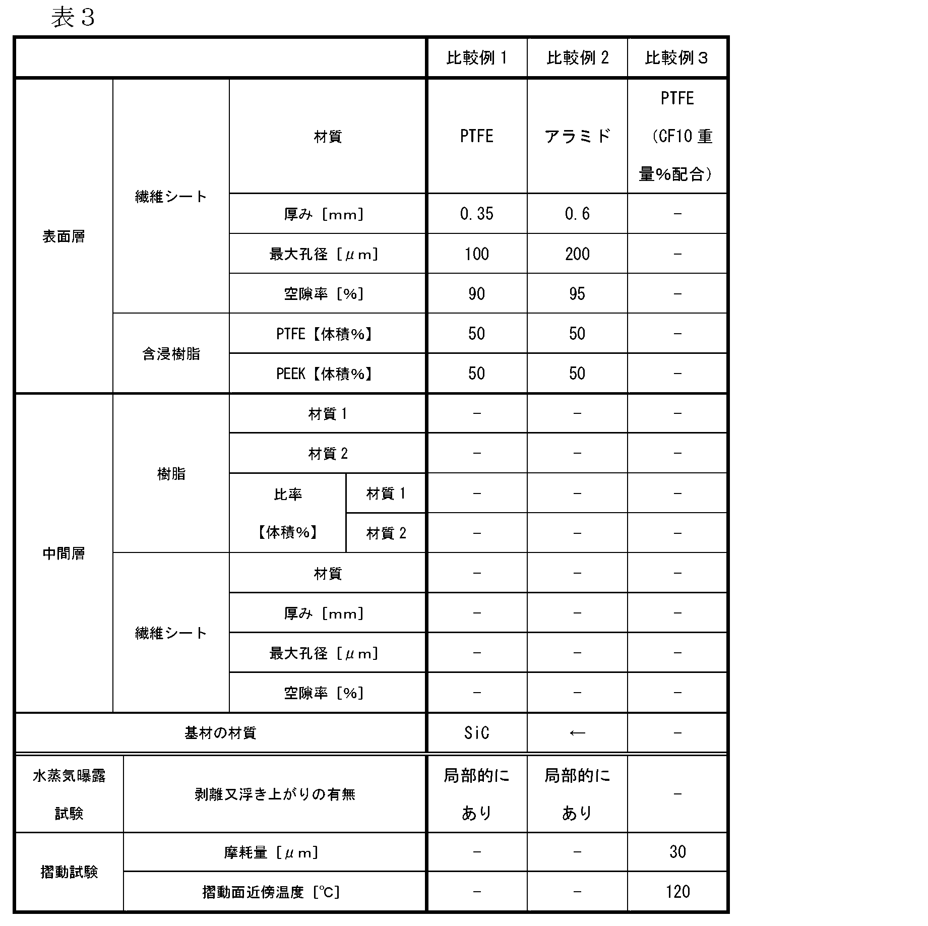
本発明の摺動部材は、メカニカルシール、セグメントシール、リップシール等の回転機器のシール部材等として利用することできる。
The sliding member of the present invention can be used as a sealing member for rotating equipment such as a mechanical seal, a segment seal, and a lip seal.
101、201 摺動部材
102、202 基材
103、203 中間層
104、204 表面層
105、205 繊維シート
106 フッ素系樹脂
107 フッ素系樹脂以外の熱可塑性樹脂
208 繊維シート
301 電気炉
302、402、502、602 基材
303、403、503、603 中間層用部材
304、404、504、604 表面層用部材
305、405、505、605 フッ素系樹脂
306、406、506、606 フッ素系樹脂以外の熱可塑性樹脂
307 熱処理板
308 重り
309 ヒーター
701 空洞
702 基材
703 中間層
704 表面層
901 回転用密封環(摺動部材)
902 回転用密封環の摺動面
903 固定用密封環(摺動部材)
904 固定用密封環の摺動面
905 回転軸
906 中間リング
907 Oリング
908 Oリング
909 複数のばね
910 ハウジング 101, 201 Sliding member 102, 202 Base material 103, 203 Intermediate layer 104, 204 Surface layer 105, 205 Fiber sheet 106 Fluorine resin 107 Thermoplastic resin other than fluorine resin 208 Fiber sheet 301 Electric furnace 302, 402, 502 , 602 Base material 303, 403, 503, 603 Intermediate layer member 304, 404, 504, 604 Surface layer member 305, 405, 505, 605 Fluororesin 306, 406, 506, 606 Thermoplastic other than fluorinated resin Resin 307 Heat treatment plate 308 Weight 309 Heater 701 Cavity 702 Base material 703 Intermediate layer 704 Surface layer 901 For rotation Fuwa (sliding member)
902 Sliding surface of sealing ring forrotation 903 Sealing ring for fixing (sliding member)
904 Sliding surface of sealing ring for fixing 905Rotating shaft 906 Intermediate ring 907 O-ring 908 O-ring 909 Multiple springs 910 Housing
102、202 基材
103、203 中間層
104、204 表面層
105、205 繊維シート
106 フッ素系樹脂
107 フッ素系樹脂以外の熱可塑性樹脂
208 繊維シート
301 電気炉
302、402、502、602 基材
303、403、503、603 中間層用部材
304、404、504、604 表面層用部材
305、405、505、605 フッ素系樹脂
306、406、506、606 フッ素系樹脂以外の熱可塑性樹脂
307 熱処理板
308 重り
309 ヒーター
701 空洞
702 基材
703 中間層
704 表面層
901 回転用密封環(摺動部材)
902 回転用密封環の摺動面
903 固定用密封環(摺動部材)
904 固定用密封環の摺動面
905 回転軸
906 中間リング
907 Oリング
908 Oリング
909 複数のばね
910 ハウジング 101, 201 Sliding
902 Sliding surface of sealing ring for
904 Sliding surface of sealing ring for fixing 905
Claims (13)
- 基材と、
前記基材上に設けられ、フッ素樹脂を含み、摺動面を有する表面層と、を有する摺動部材であって、
前記表面層と前記基材との間に繊維シートを含む中間層を有し、
前記中間層が、前記繊維シートの表面層側繊維間隙にフッ素系樹脂を、前記繊維シートの基材側繊維間隙にフッ素系樹脂以外の熱可塑性樹脂を含むことを特徴とする摺動部材。 A substrate;
A sliding member provided on the base material, including a fluororesin and having a sliding surface,
Having an intermediate layer comprising a fiber sheet between the surface layer and the substrate;
The sliding member, wherein the intermediate layer includes a fluorine-based resin in a surface layer side fiber gap of the fiber sheet, and a thermoplastic resin other than the fluorine-based resin in a base material side fiber gap of the fiber sheet. - 前記表面層に含まれるフッ素系樹脂が、ポリテトラフルオロエチレン(PTFE)、テトラフルオロエチレン・パーフルオロアルキルビニルエーテル共重合体(PFA)、及びテトラフルオロエチレン・ヘキサフルオロプロピレン共重合体(FEP)からなる群より選択される少なくとも1種の樹脂である、請求項1に記載の摺動部材。 The fluororesin contained in the surface layer is made of polytetrafluoroethylene (PTFE), tetrafluoroethylene / perfluoroalkyl vinyl ether copolymer (PFA), and tetrafluoroethylene / hexafluoropropylene copolymer (FEP). The sliding member according to claim 1, wherein the sliding member is at least one resin selected from the group.
- 前記表面層が、繊維シートを含む層である、請求項1又は2に記載の摺動部材。 The sliding member according to claim 1 or 2, wherein the surface layer is a layer containing a fiber sheet.
- 前記中間層に含まれるフッ素系樹脂が、ポリテトラフルオロエチレン(PTFE)、テトラフルオロエチレン・パーフルオロアルキルビニルエーテル共重合体(PFA)、テトラフルオロエチレン・ヘキサフルオロプロピレン共重合体(FEP)、ポリビニリデンジフルオライド(PVDF)、テトラフルオロエチレン・エチレン共重合体(ETFE)、及びポリクロロトリフルオロエチレン(PCTFE)からなる群より選択される少なくとも1種の樹脂である、請求項1~3の何れか1項に記載の摺動部材。 The fluororesin contained in the intermediate layer is polytetrafluoroethylene (PTFE), tetrafluoroethylene / perfluoroalkyl vinyl ether copolymer (PFA), tetrafluoroethylene / hexafluoropropylene copolymer (FEP), or polyvinylidene. The resin according to any one of claims 1 to 3, which is at least one resin selected from the group consisting of difluoride (PVDF), tetrafluoroethylene / ethylene copolymer (ETFE), and polychlorotrifluoroethylene (PCTFE). The sliding member according to claim 1.
- 前記中間層に含まれるフッ素系樹脂以外の熱可塑性樹脂が、ポリエーテルエーテルケトン(PEEK)、ポリフェニレンサルファイド(PPS)、ポリエーテルサルフォン(PES)、ポリイミド(PI)、ポリアミドイミド(PAI)、ポリサルフォン(PSF)、ポリアリレート(PAR)、及びポリエーテルイミド(PEI)からなる群より選択される少なくとも1種の樹脂である、請求項1~4の何れか1項に記載の摺動部材。 The thermoplastic resin other than the fluororesin contained in the intermediate layer is polyether ether ketone (PEEK), polyphenylene sulfide (PPS), polyether sulfone (PES), polyimide (PI), polyamideimide (PAI), polysulfone. The sliding member according to any one of claims 1 to 4, which is at least one resin selected from the group consisting of (PSF), polyarylate (PAR), and polyetherimide (PEI).
- 前記中間層に含まれる繊維シートが、アラミド樹脂、フッ素系樹脂、ポリアミド系樹脂、ポリエステル系樹脂、アクリル系樹脂、ポリビニルアルコール系樹脂、ポリオレフィン系樹脂、ポリウレタン樹脂、セルロース系樹脂、及びカーボン繊維からなる群より選択される少なくとも1種で構成されたシートである、請求項1~5の何れか1項に記載の摺動部材。 The fiber sheet contained in the intermediate layer is made of an aramid resin, a fluorine resin, a polyamide resin, a polyester resin, an acrylic resin, a polyvinyl alcohol resin, a polyolefin resin, a polyurethane resin, a cellulose resin, and a carbon fiber. The sliding member according to any one of claims 1 to 5, which is a sheet composed of at least one selected from the group.
- 前記基材が、カーボン、セラミックス、及び金属からなる群より選択される少なくとも1種の材料で構成された基材である、請求項1~6の何れか1項に記載の摺動部材。 The sliding member according to any one of claims 1 to 6, wherein the base material is a base material made of at least one material selected from the group consisting of carbon, ceramics, and metal.
- 請求項1~7の何れか1項に記載の摺動部材を備えるメカニカルシール。 A mechanical seal comprising the sliding member according to any one of claims 1 to 7.
- 摺動面にフッ素系樹脂を含む表面層を有する摺動部材の製造方法であって、
フッ素系樹脂を含む表面層用部材、繊維シートを含む中間層用部材、及び基材を準備する準備工程、並びに
前記表面層用部材と前記中間層用部材の一面、及び前記中間層用部材の他面と前記基材を熱圧着する熱圧着工程
を含むことを特徴とする摺動部材の製造方法。 A method for producing a sliding member having a surface layer containing a fluorine resin on a sliding surface,
A surface layer member containing a fluororesin, an intermediate layer member containing a fiber sheet, and a preparation step of preparing a substrate, and one surface of the surface layer member and the intermediate layer member, and the intermediate layer member The manufacturing method of the sliding member characterized by including the thermocompression-bonding process of thermocompression bonding the other surface and the said base material. - 前記中間層用部材が、前記繊維シートにフッ素系樹脂以外の熱可塑性樹脂を含浸した部材であり、
前記熱圧着工程において、前記表面層用部材に含まれるフッ素系樹脂が前記中間層用部材に含まれる繊維シートに浸透する、請求項9に記載の摺動部材の製造方法。 The intermediate layer member is a member obtained by impregnating the fiber sheet with a thermoplastic resin other than a fluorine resin,
The method for manufacturing a sliding member according to claim 9, wherein in the thermocompression bonding step, the fluororesin contained in the surface layer member penetrates into the fiber sheet contained in the intermediate layer member. - 前記中間層用部材が、前記繊維シートにフッ素系樹脂を含浸した部材で、前記基材が、表面にフッ素系樹脂以外の熱可塑性樹脂が塗布された基材であり、
前記熱圧着工程において、前記基材に塗布されたフッ素系樹脂以外の熱可塑性樹脂が前記中間層用部材に含まれる繊維シートに浸透する、請求項9に記載の摺動部材の製造方法。 The intermediate layer member is a member in which the fiber sheet is impregnated with a fluororesin, and the base material is a base material coated with a thermoplastic resin other than the fluororesin on the surface,
The manufacturing method of the sliding member according to claim 9, wherein in the thermocompression bonding step, a thermoplastic resin other than the fluorine-based resin applied to the base material penetrates into the fiber sheet included in the intermediate layer member. - 前記基材が、表面にフッ素系樹脂以外の熱可塑性樹脂が塗布された基材であり、
前記熱圧着工程において、前記表面層用部材に含まれるフッ素系樹脂と前記基材に塗布されたフッ素系樹脂以外の熱可塑性樹脂が前記中間層用部材に含まれる繊維シートに浸透する、請求項9に記載の摺動部材の製造方法。 The substrate is a substrate having a surface coated with a thermoplastic resin other than a fluorine-based resin,
The thermoplastic resin other than the fluororesin contained in the surface layer member and the fluororesin applied to the base material penetrates into the fiber sheet contained in the intermediate layer member in the thermocompression bonding step. The manufacturing method of the sliding member of Claim 9. - 前記中間層用部材が、前記繊維シートの一面にフッ素系樹脂を、前記繊維シートの他面にフッ素系樹脂以外の熱可塑性樹脂を含浸した部材であり、
前記熱圧着工程において、前記表面層用部材と前記中間層用部材のフッ素系樹脂を含浸した面、及び前記中間層用部材のフッ素系樹脂以外の熱可塑性樹脂を含浸した面と前記基材を熱圧着する、請求項9に記載の摺動部材の製造方法。 The intermediate layer member is a member obtained by impregnating one surface of the fiber sheet with a fluororesin and the other surface of the fiber sheet with a thermoplastic resin other than the fluororesin,
In the thermocompression bonding step, the surface layer member and the intermediate layer member impregnated with a fluorine resin, and the intermediate layer member impregnated with a thermoplastic resin other than the fluorine resin and the base material The manufacturing method of the sliding member of Claim 9 which thermocompression-bonds.
Priority Applications (3)
| Application Number | Priority Date | Filing Date | Title |
|---|---|---|---|
| EP16830529.0A EP3330581B1 (en) | 2015-07-28 | 2016-07-26 | Sliding member and method for producing a sliding member |
| JP2017530886A JP6742673B2 (en) | 2015-07-28 | 2016-07-26 | Sliding member and method of manufacturing sliding member |
| CN201680037644.5A CN107709853B (en) | 2015-07-28 | 2016-07-26 | The manufacturing method of slide unit and slide unit |
Applications Claiming Priority (2)
| Application Number | Priority Date | Filing Date | Title |
|---|---|---|---|
| JP2015-148902 | 2015-07-28 | ||
| JP2015148902 | 2015-07-28 |
Publications (1)
| Publication Number | Publication Date |
|---|---|
| WO2017018424A1 true WO2017018424A1 (en) | 2017-02-02 |
Family
ID=57885726
Family Applications (1)
| Application Number | Title | Priority Date | Filing Date |
|---|---|---|---|
| PCT/JP2016/071907 WO2017018424A1 (en) | 2015-07-28 | 2016-07-26 | Sliding member and production method for sliding member |
Country Status (4)
| Country | Link |
|---|---|
| EP (1) | EP3330581B1 (en) |
| JP (1) | JP6742673B2 (en) |
| CN (1) | CN107709853B (en) |
| WO (1) | WO2017018424A1 (en) |
Families Citing this family (3)
| Publication number | Priority date | Publication date | Assignee | Title |
|---|---|---|---|---|
| CN111365373A (en) | 2018-12-25 | 2020-07-03 | 浙江中达精密部件股份有限公司 | Sliding bearing and manufacturing method thereof |
| CN111038050B (en) * | 2019-12-03 | 2021-11-05 | 合肥一密科技有限公司 | Self-lubricating and high-wear-resistance non-metal sealing sliding block and manufacturing method thereof |
| CN111155224A (en) * | 2020-02-17 | 2020-05-15 | 上海市纺织科学研究院有限公司 | Preparation method of polyarylester fiber-based self-lubricating fabric |
Citations (4)
| Publication number | Priority date | Publication date | Assignee | Title |
|---|---|---|---|---|
| JPS56160423A (en) * | 1980-05-09 | 1981-12-10 | Yunipura Kk | Sliding member and manufacturing method |
| JPS61179415U (en) * | 1985-04-26 | 1986-11-08 | ||
| JPS6263220A (en) * | 1985-09-12 | 1987-03-19 | Oiles Ind Co Ltd | Sliding member |
| JP2010174227A (en) * | 2009-02-02 | 2010-08-12 | Eagle Ind Co Ltd | Sliding member and mechanical seal |
Family Cites Families (3)
| Publication number | Priority date | Publication date | Assignee | Title |
|---|---|---|---|---|
| US4111499A (en) * | 1975-03-31 | 1978-09-05 | The Heim Universal Corporation | Bearing assembly and liner |
| CN103182808A (en) * | 2011-12-28 | 2013-07-03 | 圣戈班高功能塑料集团 | Multilayer complex comprising fluorine-containing polymer surface layer and non-fluorinated polymer transition layer |
| US10307991B2 (en) * | 2013-09-30 | 2019-06-04 | Saint-Gobain Performance Plastics Pampus Gmbh | Laminates with fluoropolymer cloth |
-
2016
- 2016-07-26 JP JP2017530886A patent/JP6742673B2/en active Active
- 2016-07-26 EP EP16830529.0A patent/EP3330581B1/en active Active
- 2016-07-26 CN CN201680037644.5A patent/CN107709853B/en active Active
- 2016-07-26 WO PCT/JP2016/071907 patent/WO2017018424A1/en unknown
Patent Citations (4)
| Publication number | Priority date | Publication date | Assignee | Title |
|---|---|---|---|---|
| JPS56160423A (en) * | 1980-05-09 | 1981-12-10 | Yunipura Kk | Sliding member and manufacturing method |
| JPS61179415U (en) * | 1985-04-26 | 1986-11-08 | ||
| JPS6263220A (en) * | 1985-09-12 | 1987-03-19 | Oiles Ind Co Ltd | Sliding member |
| JP2010174227A (en) * | 2009-02-02 | 2010-08-12 | Eagle Ind Co Ltd | Sliding member and mechanical seal |
Also Published As
| Publication number | Publication date |
|---|---|
| CN107709853B (en) | 2019-12-03 |
| CN107709853A (en) | 2018-02-16 |
| JP6742673B2 (en) | 2020-08-19 |
| EP3330581B1 (en) | 2020-01-01 |
| EP3330581A4 (en) | 2018-12-26 |
| JPWO2017018424A1 (en) | 2018-05-17 |
| EP3330581A1 (en) | 2018-06-06 |
Similar Documents
| Publication | Publication Date | Title |
|---|---|---|
| JP5615293B2 (en) | Sliding element and method for manufacturing the same | |
| JP5107702B2 (en) | Mechanical seal device, sliding component and manufacturing method thereof | |
| US9981284B2 (en) | Method of forming a laminate | |
| WO2017018424A1 (en) | Sliding member and production method for sliding member | |
| US3950599A (en) | Low-friction laminate liner for bearings | |
| JP5342883B2 (en) | Double layer bearing | |
| JP4812823B2 (en) | Multilayer bearing manufacturing method | |
| JP5859183B2 (en) | Sliding face material and multilayer sliding member provided with the sliding face material | |
| JPH10204282A (en) | Sliding member for wet type radical bearing | |
| WO2015111574A1 (en) | Slide member | |
| EP2905487B1 (en) | Multilayer sliding member and method for manufacturing multilayer sliding members | |
| TW591146B (en) | Nonwoven material for low friction bearing surfaces | |
| WO2019031154A1 (en) | Multilayered seamless belt and production method therefor | |
| JP5215630B2 (en) | Sliding member | |
| JP2006349070A (en) | Packing material, gland packing using this packing material, manufacturing method for packing material, and manufacturing method for gland packing | |
| JP5691553B2 (en) | Pressure-resistant sliding member and brake pad | |
| JP4519355B2 (en) | Underwater sliding member and manufacturing method thereof | |
| KR101910155B1 (en) | Method for manufacturing surface contact bearing with carbon fiber fabric - fluoride resin composite | |
| TWI762477B (en) | Buffer material for hot pressing | |
| JP2004256592A (en) | Composite particle, composite member, composite film, and methods for producing them | |
| CN108253024A (en) | Multilayer materials including fluoropolymer surface Yu nonfluorinated polymers transition zone | |
| JP4260156B2 (en) | Friction material and manufacturing method thereof | |
| WO2022209966A1 (en) | Sliding component | |
| JPS6263220A (en) | Sliding member | |
| JP6610042B2 (en) | Sliding member and brake member for wind turbine yaw control |
Legal Events
| Date | Code | Title | Description |
|---|---|---|---|
| 121 | Ep: the epo has been informed by wipo that ep was designated in this application |
Ref document number: 16830529 Country of ref document: EP Kind code of ref document: A1 |
|
| ENP | Entry into the national phase |
Ref document number: 2017530886 Country of ref document: JP Kind code of ref document: A |
|
| NENP | Non-entry into the national phase |
Ref country code: DE |