WO2017015910A1 - Dispositif d'émission, dispositif de réception et procédé pour des données de liaison montante - Google Patents
Dispositif d'émission, dispositif de réception et procédé pour des données de liaison montante Download PDFInfo
- Publication number
- WO2017015910A1 WO2017015910A1 PCT/CN2015/085470 CN2015085470W WO2017015910A1 WO 2017015910 A1 WO2017015910 A1 WO 2017015910A1 CN 2015085470 W CN2015085470 W CN 2015085470W WO 2017015910 A1 WO2017015910 A1 WO 2017015910A1
- Authority
- WO
- WIPO (PCT)
- Prior art keywords
- symbol
- uplink
- contention resource
- uplink data
- data
- Prior art date
Links
Images


Classifications
-
- H—ELECTRICITY
- H04—ELECTRIC COMMUNICATION TECHNIQUE
- H04L—TRANSMISSION OF DIGITAL INFORMATION, e.g. TELEGRAPHIC COMMUNICATION
- H04L27/00—Modulated-carrier systems
- H04L27/26—Systems using multi-frequency codes
- H04L27/2601—Multicarrier modulation systems
- H04L27/2602—Signal structure
- H04L27/261—Details of reference signals
- H04L27/2613—Structure of the reference signals
-
- H—ELECTRICITY
- H04—ELECTRIC COMMUNICATION TECHNIQUE
- H04W—WIRELESS COMMUNICATION NETWORKS
- H04W72/00—Local resource management
- H04W72/12—Wireless traffic scheduling
-
- H—ELECTRICITY
- H04—ELECTRIC COMMUNICATION TECHNIQUE
- H04W—WIRELESS COMMUNICATION NETWORKS
- H04W72/00—Local resource management
- H04W72/20—Control channels or signalling for resource management
- H04W72/21—Control channels or signalling for resource management in the uplink direction of a wireless link, i.e. towards the network
-
- H—ELECTRICITY
- H04—ELECTRIC COMMUNICATION TECHNIQUE
- H04W—WIRELESS COMMUNICATION NETWORKS
- H04W74/00—Wireless channel access, e.g. scheduled or random access
- H04W74/002—Transmission of channel access control information
- H04W74/006—Transmission of channel access control information in the downlink, i.e. towards the terminal
-
- H—ELECTRICITY
- H04—ELECTRIC COMMUNICATION TECHNIQUE
- H04W—WIRELESS COMMUNICATION NETWORKS
- H04W74/00—Wireless channel access, e.g. scheduled or random access
- H04W74/02—Hybrid access techniques
-
- H—ELECTRICITY
- H04—ELECTRIC COMMUNICATION TECHNIQUE
- H04W—WIRELESS COMMUNICATION NETWORKS
- H04W74/00—Wireless channel access, e.g. scheduled or random access
- H04W74/08—Non-scheduled or contention based access, e.g. random access, ALOHA, CSMA [Carrier Sense Multiple Access]
-
- H—ELECTRICITY
- H04—ELECTRIC COMMUNICATION TECHNIQUE
- H04L—TRANSMISSION OF DIGITAL INFORMATION, e.g. TELEGRAPHIC COMMUNICATION
- H04L5/00—Arrangements affording multiple use of the transmission path
- H04L5/0001—Arrangements for dividing the transmission path
- H04L5/0003—Two-dimensional division
- H04L5/0005—Time-frequency
- H04L5/0007—Time-frequency the frequencies being orthogonal, e.g. OFDM(A), DMT
-
- H—ELECTRICITY
- H04—ELECTRIC COMMUNICATION TECHNIQUE
- H04W—WIRELESS COMMUNICATION NETWORKS
- H04W72/00—Local resource management
- H04W72/04—Wireless resource allocation
- H04W72/044—Wireless resource allocation based on the type of the allocated resource
- H04W72/0446—Resources in time domain, e.g. slots or frames
Definitions
- the present invention relates to the field of communications, and in particular, to an uplink data transmitting apparatus, a receiving apparatus, and a method.
- the user equipment (English: User Equipment, UE for short) is usually sent to the evolved base station (English: Evolved Node B, eNB for short) based on the scheduled transmission mode. Upstream data.
- the UE When the UE needs to send the uplink data, the UE first needs to send an uplink scheduling request to the eNB (English: Scheduling Request, SR for short); the eNB configures an uplink scheduling grant to the UE according to the SR (English: Up Link Grant, referred to as UL Grant)
- the UL Grant is used to configure an uplink transmission resource to the UE.
- the UE correctly decodes and obtains the UL Grant the UE sends uplink data to the eNB according to the uplink transmission resource configured by the eNB.
- the entire process takes about 22.5ms.
- a contention-based (Contention Based, CB) transmission method is proposed.
- the eNB configures the same uplink contention resources to multiple user equipments in advance.
- the UE needs to transmit uplink data
- the UE sends the uplink data to the eNB by using the latest uplink contention resource.
- a contention conflict may occur.
- an embodiment of the present invention provides an uplink data sending apparatus, a receiving apparatus, and a method.
- an embodiment of the present invention provides an uplink data sending apparatus, where the apparatus includes:
- a determining module configured to determine an uplink contention resource, where the uplink contention resource includes an SR symbol used for transmitting an uplink scheduling request SR and a shared symbol used for transmitting uplink data;
- a sending module configured to send the SR by using the SR symbol in the uplink contention resource
- the sending module is configured to send the uplink data by using the shared symbol in the uplink contention resource.
- the sending module is configured to send the SR by using a code channel corresponding to the local UE on the SR symbol in the uplink contention resource.
- the determining module is configured to determine a code channel index that is allocated by the eNB;
- the determining module is configured to search, according to the pre-stored first correspondence, a first cyclic shift value and a first time domain orthogonal code corresponding to the code channel index;
- the determining module configured to process the predetermined base sequence by the first cyclic shift value and the first time domain orthogonal code to generate the SR;
- the determining module is configured to send, by using the SR, the SR symbol in the uplink contention resource.
- the sending module is configured to send the uplink in a multi-user multiple input multiple MU-MIMO manner on the shared symbol in the uplink contention resource. data.
- the shared symbol comprises: a reference symbol for transmitting a demodulation reference signal DM-RS and for transmitting Data symbols of the uplink data;
- the determining module is configured to determine a code channel index allocated by the eNB
- the determining module is configured to search, according to the pre-stored second correspondence, a pilot index corresponding to the code channel index, and a second cyclic shift value and a second time domain positive corresponding to the pilot index Transmitting; for processing a predetermined base sequence by the second cyclic shift value and the second time domain orthogonal code to generate the DM-RS;
- the sending module is configured to send the DM-RS to the reference symbol in the uplink contention resource for sending;
- the sending module is configured to send the uplink data to the data symbol in the uplink contention resource for transmission.
- the uplink data includes: a modulation and coding policy MCS and data that is currently transmitted;
- the sending module is configured to carry the MCS and the data currently transmitted in the uplink contention resource for multiplexing transmission;
- the channel coding code rate used by the MCS is lower than the channel coding rate used by the data currently transmitted.
- the device further includes a receiving module
- the determining module is configured to acquire the UE identifier allocated by the eNB, where the UE identifier includes a contention access cell radio network temporary identifier CA-RNTI or a semi-persistent scheduling contention cell radio network temporary identifier SPS-CA-RNTI;
- the receiving module is configured to receive downlink control information DCI from the physical downlink control channel PDCCH according to the UE identifier;
- the determining module is configured to determine, from the DCI, an uplink contention resource configured by the eNB;
- the DCI adopts a DCI format format0 including an extended field, where the original field of the DCI format0 includes: a starting position and a quantity of the resource block occupied by the uplink contention resource, where the uplink contention resource is The symbol information corresponding to the shared symbol; the extension field includes symbol information for indicating the SR symbol; or the DCI uses the DCI format CA, where the DCI format CA includes: a starting position of the resource block occupied by the uplink contention resource And the number, the symbol information of the SR symbol and the symbol information corresponding to the shared symbol.
- the device further includes:
- a receiving module configured to receive non-acknowledgment NACK information fed back by the eNB, where the NACK information is sent when the eNB successfully receives the SR but fails to receive the uplink data corresponding to the SR;
- the receiving module is configured to receive an uplink scheduling grant UL Grant that is sent by the eNB, where the UL Grant is sent when the eNB successfully receives the SR but fails to receive the uplink data corresponding to the SR.
- the sending module is configured to resend the uplink data according to the UL Grant.
- an uplink data receiving apparatus where the apparatus includes:
- a configuration module configured to configure, for a plurality of user equipments, an uplink contention resource, where the uplink contention resource includes an SR symbol used for transmitting an uplink scheduling request SR and a shared symbol used for transmitting uplink data;
- a receiving module configured to receive the SR by using the SR symbol in the uplink contention resource
- the receiving module is configured to receive the uplink data by using the shared symbol in the uplink contention resource.
- the receiving module is configured to receive the SR by using a code channel corresponding to each of the UEs on the SR symbol of the uplink contention resource.
- the device further includes: a processing module
- the configuration module is configured to allocate a corresponding code channel index to the UE
- the processing module is configured to search, according to the pre-stored first correspondence, a first cyclic shift value and a first time domain orthogonal code corresponding to each of the code channel indexes;
- the processing module is configured to detect, according to the first cyclic shift value and the first time domain orthogonal code, whether a signal energy on a code channel corresponding to the code channel index on the SR symbol reaches a predetermined threshold ;
- the processing module is configured to determine, if the predetermined threshold is reached, the SR that is sent by the UE that is corresponding to the code channel index.
- the receiving module is configured to receive, by using the multi-user multiple input multiple output MU-MIMO mode, on the shared symbol in the uplink contention resource.
- the upstream data is described.
- the shared symbol includes: a reference symbol for transmitting a demodulation reference signal DM-RS and is used for transmission The data symbol of the uplink data; the device further includes: a processing module;
- the configuration module is configured to allocate a corresponding code channel index to the UE
- the processing module is configured to determine, according to each of the SRs that are successfully received, the code track index corresponding to the SR;
- the processing module is configured to search, according to the pre-stored second correspondence, a pilot index corresponding to the code channel index, and a second cyclic shift value and a second time domain positive corresponding to the pilot index Cross code
- the processing module is configured to perform channel estimation on the demodulation reference signal DM-RS carried in the reference symbol of the uplink contention resource according to the second cyclic shift value and the second time domain orthogonal code. , obtaining channel estimation results;
- the processing module data decoding unit is configured to perform multi-user multiple input and multiple MU-MIMO decoding on the data symbols in the uplink contention resource according to the channel estimation result to obtain the uplink data.
- the uplink data includes: a modulation and coding policy MCS and data that is currently transmitted;
- the processing module is configured to perform demodulation and channel decoding on the data currently transmitted according to the MCS.
- the device further includes: a sending module;
- the configuration module is configured to allocate a corresponding UE identifier to the UE
- the sending module is configured to, for each UE, send downlink control information DCI on the physical downlink control channel PDCCH according to the UE identifier;
- the DCI adopts a DCI format format0 including an extended field, where the original field of the DCI format0 includes: a starting position and a quantity of the resource block occupied by the uplink contention resource, where the uplink contention resource is The symbol information corresponding to the shared symbol; the extension field includes symbol information for indicating the SR symbol; or the DCI uses the DCI format CA, where the DCI format CA includes: a starting position of the resource block occupied by the uplink contention resource And the number, the symbol information of the SR symbol, and the symbol information corresponding to the shared symbol.
- the device further includes:
- a generating module configured to generate non-acknowledgment NACK information when the SR is successfully received but fails to receive the uplink data corresponding to the SR
- a sending module configured to send to the UE corresponding to the SR The NACK information
- the generating module is configured to: when the SR is successfully received but the uplink data corresponding to the SR is not successfully received, generate an uplink scheduling grant UL Grant for the UE corresponding to the SR; And a module, configured to send the UL Grant to the UE corresponding to the SR.
- an embodiment of the present invention provides a user equipment, where the user equipment includes: a processor, a memory, and a transceiver, where the memory is used to store one or more instructions, and the instructions are configured to Executed by the processor;
- the processor is configured to determine an uplink contention resource, where the uplink contention resource is used for transmission The SR symbol of the row scheduling request SR and the shared symbol for transmitting the uplink data;
- the processor is further configured to control the transceiver to send the SR by using the SR symbol in the uplink contention resource;
- the processor is further configured to control the transceiver to send the uplink data by using the shared symbol in the uplink contention resource.
- the processor is further configured to, on the SR symbol in the uplink contention resource, control the transceiver to send by using a code channel corresponding to the local UE.
- the SR is further configured to, on the SR symbol in the uplink contention resource, control the transceiver to send by using a code channel corresponding to the local UE.
- the processor is further configured to determine a code channel index that is allocated by the eNB;
- the processor is further configured to: find, according to the pre-stored first correspondence, a first cyclic shift value and a first time domain orthogonal code corresponding to the code channel index;
- the processor is further configured to: process the predetermined base sequence by the first cyclic shift value and the first time domain orthogonal code to generate the SR;
- the processor is further configured to control the transceiver to send the SR on the SR symbol in the uplink contention resource for transmission.
- the processor is configured to control, by using the shared symbol in the uplink contention resource, the transceiver to send the uplink data in a multi-user multiple input multiple output MU-MIMO manner.
- the shared symbol includes: a reference symbol for transmitting a demodulation reference signal DM-RS and is used for transmission Data symbols of the uplink data;
- the processor is further configured to determine a code channel index allocated by the eNB;
- the processor is further configured to: find, according to the pre-stored second correspondence, a pilot index corresponding to the code channel index, and a second cyclic shift value and a second time domain corresponding to the pilot index Orthogonal code
- the processor is further configured to: process the predetermined base sequence by the second cyclic shift value and the second time domain orthogonal code to generate the DM-RS;
- the processor is further configured to control, by the transceiver, that the DM-RS is carried on the reference symbol in the uplink contention resource, and the uplink data is carried in the uplink contention resource.
- the data symbol is transmitted on.
- the uplink data includes a modulation and coding policy MCS and data transmitted this time;
- the processor is further configured to carry the MCS and the data currently transmitted in the uplink contention resource for multiplexing transmission;
- the channel coding code rate used by the MCS is lower than the channel coding rate used by the data currently transmitted.
- the processor is configured to:
- the processor is further configured to acquire a UE identifier allocated by the eNB, where the UE identifier includes a contention access cell radio network temporary identifier CA-RNTI or a semi-persistent scheduling contention cell radio network temporary identifier SPS-CA-RNTI ;
- the processor is further configured to control the transceiver to receive downlink control information DCI from a physical downlink control channel PDCCH according to the UE identifier;
- the processor is further configured to determine, from the DCI, an uplink contention resource configured by the eNB;
- the DCI adopts a DCI format format0 including an extended field, where the original field of the DCI format0 includes: a starting position and a quantity of the resource block occupied by the uplink contention resource, where the uplink contention resource is The symbol information corresponding to the shared symbol; the extension field includes symbol information for indicating the SR symbol; or the DCI uses the DCI format CA, where the DCI format CA includes: a starting position of the resource block occupied by the uplink contention resource And the number, the symbol information of the SR symbol and the symbol information corresponding to the shared symbol.
- the processor is further configured to control the transceiver to receive the non-acknowledgment NACK information fed back by the eNB, where the NACK information is that the eNB successfully receives the SR but fails to receive the corresponding location of the SR. Sent when the uplink data is described;
- the processor is further configured to control the transceiver to receive an uplink scheduling grant UL Grant fed back by the eNB, where the UL Grant is that the eNB successfully receives the SR but fails to receive the Transmitted when the uplink data corresponding to the SR is sent; and the transceiver is controlled to resend the uplink data according to the UL Grant.
- an embodiment of the present invention provides an evolved base station, where the base station includes: a processor, a memory, and a transceiver, where the memory is configured to store one or more instructions, where the instructions are configured to be configured by Executing by the processor;
- the processor is configured to configure an uplink contention resource for the multiple user equipments, where the uplink contention resource includes an SR symbol for transmitting an uplink scheduling request SR and a shared symbol for transmitting uplink data.
- the processor is further configured to control the transceiver to receive the SR by using the SR symbol in the uplink contention resource;
- the processor is further configured to control the transceiver to receive the uplink data by using the shared symbol in the uplink contention resource.
- the processor is configured to:
- the transceiver is controlled to receive the SR by using a code channel corresponding to each of the UEs.
- the processor is further configured to allocate a corresponding code channel index to the UE;
- the processor is further configured to: find, according to the pre-stored first correspondence, a first cyclic shift value and a first time domain orthogonal code corresponding to each of the code channel indexes;
- the processor is further configured to detect, according to the first cyclic shift value and the first time domain orthogonal code, whether a signal energy on a code channel corresponding to the code channel index on the SR symbol reaches a predetermined time Threshold value
- the processor is further configured to: if the predetermined threshold is reached, determine to receive the SR sent by the UE corresponding to the code channel index.
- the processor is further configured to, on the shared symbol in the uplink contention resource, control the transceiver to receive the uplink data that is sent by using a multi-user multiple input multiple output MU-MIMO mode.
- the shared symbol includes: a reference symbol for transmitting a demodulation reference signal DM-RS and is used for transmission Data symbols of the uplink data;
- the processor is further configured to allocate a corresponding code channel index to the UE;
- the processor is further configured to determine, according to each of the SRs that are successfully received, the code track index corresponding to the SR;
- the processor is further configured to: find, according to the pre-stored second correspondence, a pilot index corresponding to the code channel index, and a second cyclic shift value and a second time domain corresponding to the pilot index Orthogonal code
- the processor is further configured to perform, according to the second cyclic shift value and the second time domain orthogonal code, a channel of a demodulation reference signal DM-RS carried in the reference symbol of the uplink contention resource. Estimate, get the channel estimation result;
- the processor is further configured to perform multi-user multiple input and multiple MU-MIMO decoding on the data symbols in the uplink contention resource according to the channel estimation result to obtain the uplink data.
- the uplink data includes: a modulation and coding policy MCS and data that is currently transmitted;
- the processor is further configured to perform demodulation and channel decoding on the data that is currently transmitted according to the MCS.
- the processor is further configured to allocate a corresponding UE identifier to the UE;
- the processor is further configured to, for each UE, control the transceiver to send downlink control information DCI on the physical downlink control channel PDCCH according to the UE identifier;
- the DCI adopts a DCI format format0 including an extended field, where the original field of the DCI format0 includes: a starting position and a quantity of the resource block occupied by the uplink contention resource, where the uplink contention resource is The symbol information corresponding to the shared symbol; the extension field includes symbol information for indicating the SR symbol; or the DCI uses the DCI format CA, where the DCI format CA includes: a starting position of the resource block occupied by the uplink contention resource And the number, the symbol information of the SR symbol, and the symbol information corresponding to the shared symbol.
- the processor is further configured to successfully receive the SR but fail to receive the SR pair successfully
- the non-acknowledgment NACK information is generated when the uplink data is received; the processor is further configured to control the transceiver to send the NACK information to the UE corresponding to the SR;
- the processor is further configured to: when the SR is successfully received but the uplink data corresponding to the SR is not successfully received, generate an uplink scheduling grant UL Grant for the UE corresponding to the SR; And for controlling the transceiver to send the UL Grant to the UE corresponding to the SR.
- an embodiment of the present invention provides an uplink data sending and receiving system, where the uplink data sending and receiving system includes: an eNB and a UE;
- the UE includes the uplink data transmitting apparatus provided by any one of the first aspect and the various possible implementation manners of the first aspect, or the UE is any one of various possible implementation manners of the third aspect and the third aspect Provided UE;
- the eNB includes the uplink data receiving apparatus provided by any of the second aspect and any of the various possible implementation manners of the second aspect, or the eNB is any one of the fourth aspect and the fourth possible aspect of the fourth aspect Provided by the eNB.
- an embodiment of the present invention provides an uplink data sending method, where the method includes:
- the uplink contention resource includes an SR symbol for transmitting an uplink scheduling request SR and a shared symbol for transmitting uplink data
- the sending, by using the SR symbol in the uplink contention resource, the SR includes:
- the code corresponding to the UE is used on the SR symbol in the uplink contention resource Before sending the SR, the road also includes:
- the sending the uplink data by using the shared symbol in the uplink contention resource includes:
- the shared symbol includes: a reference symbol for transmitting a demodulation reference signal DM-RS and is used for transmission Data symbols of the uplink data;
- the multi-user multiple input and multiple MU-MIMO manners are also included in the shared symbol in the uplink contention resource, and the method further includes:
- Transmitting, by the multi-user multiple input and multiple MU-MIMO mode, the uplink data on the shared symbol in the uplink contention resource including:
- the DM-RS is transmitted on the reference symbol in the uplink contention resource, and the uplink data is carried on the data symbol in the uplink contention resource for transmission.
- the uplink data includes a modulation and coding policy MCS and data that is currently transmitted;
- Transmitting, by the uplink data, the data symbol in the uplink contention resource including:
- the channel coding code rate used by the MCS is lower than the channel coding rate used by the data currently transmitted.
- the determining the uplink competition resource includes:
- the UE identifier includes a contention access cell radio network temporary identifier CA-RNTI or a semi-persistent scheduling contention cell radio network temporary identifier SPS-CA-RNTI;
- the DCI adopts a DCI format format0 including an extended field, where the original field of the DCI format0 includes: a starting position and a quantity of the resource block occupied by the uplink contention resource, where the uplink contention resource is The symbol information corresponding to the shared symbol; the extension field includes symbol information for indicating the SR symbol; or the DCI uses the DCI format CA, where the DCI format CA includes: a starting position of the resource block occupied by the uplink contention resource And the number, the symbol information of the SR symbol and the symbol information corresponding to the shared symbol.
- the seventh possible implementation manner of the sixth aspect after the sending the uplink data by using the shared symbol in the uplink contention resource, ,Also includes:
- an embodiment of the present invention provides an uplink data sending method, where the method includes:
- the uplink contention resources include an SR symbol for transmitting an uplink scheduling request SR and a shared symbol for transmitting uplink data;
- the receiving, by the SR symbol in the uplink contention resource, the SR includes:
- the SR is received by a code channel corresponding to each of the UEs.
- the that, on the SR symbol of the uplink contention resource, by corresponding to each of the UEs Before the code channel receives the SR also includes:
- Receiving the SR by using a code channel corresponding to each of the UEs on the SR symbol of the uplink contention resource including:
- the receiving the uplink data by using the shared symbol in the uplink contention resource includes:
- the shared symbol includes: a reference symbol for transmitting a demodulation reference signal DM-RS and is used for transmission Data symbols of the uplink data;
- the method before the receiving, by the MU-MIMO, the uplink data on the shared symbol in the uplink contention resource, the method further includes:
- the MU-MIMO And receiving, by the MU-MIMO, the uplink data, on the shared symbol in the uplink contention resource, including:
- the uplink data includes: a modulation and coding policy MCS and data that is currently transmitted;
- the method further includes:
- a seventh possible aspect of the seventh aspect or the seventh aspect, or a second possible implementation of the seventh aspect or a third possible implementation of the seventh aspect or the fourth possible aspect of the seventh aspect includes:
- the DCI adopts a DCI format format0 including an extended field, where the original field of the DCI format0 includes: a starting position and a quantity of the resource block occupied by the uplink contention resource, where the uplink contention resource is The symbol information corresponding to the shared symbol; the extension field includes symbol information for indicating the SR symbol; or the DCI uses the DCI format CA, where the DCI format CA includes: a starting position of the resource block occupied by the uplink contention resource And the number, the symbol information of the SR symbol, and the symbol information corresponding to the shared symbol.
- a seventh possible aspect of the seventh aspect or the seventh aspect, or a second possible implementation of the seventh aspect or a third possible implementation of the seventh aspect or the fourth possible aspect of the seventh aspect in an implementation manner or a fifth possible implementation manner, in the seventh possible implementation manner of the seventh aspect, after the receiving, by the shared symbol in the uplink contention resource, the uplink data, the method further includes:
- the uplink contention resource includes an SR symbol for transmitting the SR and a shared symbol for transmitting the uplink data; the UE sends the SR to the eNB by using the SR symbol in the uplink contention resource; The shared symbol in the uplink contention resource sends the uplink data to the eNB; the eNB receives the SR of the UE by using the SR symbol in the uplink contention resource; and receives the uplink data of the UE by using the shared symbol in the uplink contention resource;
- the eNB may fail to decode the uplink data sent by each UE; and a new contention-based uplink data transmission mode is provided.
- the uplink data transmission mode can still determine which UEs send uplink data according to the successfully received SR when the eNB does not successfully receive the uplink data of the UE.
- FIG. 1 is a block diagram of an uplink data transmitting apparatus according to an embodiment of the present invention.
- FIG. 2 is a block diagram of an uplink data transmitting apparatus according to another embodiment of the present invention.
- FIG. 3 is a block diagram of an uplink data receiving apparatus according to an embodiment of the present invention.
- FIG. 4 is a block diagram of an uplink data receiving apparatus according to another embodiment of the present invention.
- FIG. 5 is a structural block diagram of a user equipment according to an embodiment of the present invention.
- FIG. 6 is a structural block diagram of a base station according to another embodiment of the present invention.
- FIG. 7 is a block diagram of an uplink data sending and receiving system according to an embodiment of the present invention.
- FIG. 8 is a flowchart of an uplink data sending method according to an embodiment of the present invention.
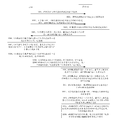
- FIG. 9A and FIG. 9B are schematic diagrams showing a frame structure of an uplink contention resource according to another embodiment of the present invention.
- FIG. 10 is a flowchart of an uplink data sending method according to another embodiment of the present invention.
- FIG. 11 is a schematic diagram of a frame structure when the MCS and the data currently transmitted are multiplexed and transmitted according to another embodiment of the present invention.
- FIG. 12 is a flowchart of an uplink data sending method according to another embodiment of the present invention.
- FIG. 13 is a flowchart of an uplink data sending method according to another embodiment of the present invention.
- Subframe In the time domain, LTE transmissions are organized into radio frames of length 10ms, each radio frame is divided into 10 subframes of the same size and length of 1ms, each subframe containing two slots of the same size, each The time slots are composed of a certain number of Orthogonal Frequency Division Multiplexing (OFDM) symbols including a cyclic prefix. If it is a regular cyclic prefix, each time slot includes 7 OFDM symbols. If the cyclic prefix is extended, each slot includes 6 OFDM symbols, hereinafter referred to as symbols.
- OFDM Orthogonal Frequency Division Multiplexing
- FIG. 1 is a block diagram of an uplink data transmitting apparatus according to an embodiment of the present invention.
- the uplink data transmitting apparatus may be implemented as all or part of the UE by software, hardware, or a combination of both.
- the uplink data device can include a determining module 110 and a sending module 120.
- the determining module 110 is configured to determine an uplink contention resource, where the uplink contention resource includes an SR symbol used for transmitting the SR and a shared symbol used for transmitting the uplink data.
- Multiple UEs may share the same uplink contention resource to send uplink data to the eNB in a contention-based manner.
- a part of the symbols in the uplink contention resources are divided into SR symbols for transmitting the SR; and another part of the symbols in the uplink contention resources are divided into shared symbols for transmitting the uplink data.
- the SR is used to indicate to the eNB that the UE has a requirement to send uplink data.
- the sending module 120 is configured to send the SR by using the SR symbol in the uplink contention resource.
- the sending module 120 is configured to send uplink data by using a shared symbol in the uplink contention resource.
- the UE first sends an SR to the eNB by using the SR symbol in the uplink contention resource, and sends the uplink data to the eNB by using the shared symbol in the uplink contention resource by confirming the uplink contention resource.
- the eNB may fail to decode all the uplink data sent by each UE, causing the uplink contention resources to be completely wasted.
- the problem is that a new contention-based uplink data transmission mode is provided. When the eNB does not successfully receive the uplink data of the UE, the uplink data transmission mode can still determine which UEs send the uplink data according to the successfully received SR. So that the upstream competitive resources will not be wasted.
- FIG. 2 is a block diagram of an uplink data transmitting apparatus according to another embodiment of the present invention.
- the uplink data transmitting apparatus may be implemented as all or part of the UE by software, hardware, or a combination of both.
- the uplink data sending apparatus may include: a determining module 110, a sending module 120, and a receiving module 130.
- the determining module 110 is configured to determine an uplink contention resource, where the uplink contention resource includes an SR symbol for transmitting an uplink SR and a shared symbol for transmitting uplink data.
- the determining module 110 is further configured to acquire the UE identifier allocated by the eNB.
- the determining module 110 is configured to receive DCI (Downlink Control Information) from the physical downlink control channel (English: Physical Downlink Control Channel, PDCCH for short) according to the UE identifier.
- DCI Downlink Control Information
- the DCI can only descramble successfully if the UE has the UE identifier.
- the determining module 110 is further configured to determine, from the DCI, an uplink contention resource configured by the eNB.
- the determining module 110 is further configured to determine a code channel index allocated by the eNB.
- the sending module 120 is configured to send the SR by using a code channel corresponding to the UE on the SR symbol in the uplink contention resource.
- the determining module 110 is further configured to search, according to the pre-stored first correspondence, the first cyclic shift value and the first time domain orthogonal code corresponding to the code channel index.
- the determining module 110 is further configured to generate a SR by processing the predetermined base sequence by the first cyclic shift value and the first time domain orthogonal code.
- the sending module 120 is configured to send the SR on the SR symbol in the uplink contention resource for transmission.
- the sending module 120 is configured to send uplink data in a multi-user multiple input multiple output (MuLtiple User-Multiple Input Multiple Output, MU-MIMO) manner on the shared symbol in the uplink contention resource.
- MuLtiple User-Multiple Input Multiple Output, MU-MIMO multi-user multiple input multiple output
- the determining module 110 is further configured to search, according to the pre-stored second correspondence, a pilot index corresponding to the code channel index, and a second cyclic shift value and a second time domain orthogonal code corresponding to the pilot index.
- the determining module 110 is further configured to process the predetermined base sequence by using the second cyclic shift value and the second time domain orthogonal code to generate a demodulation reference signal (English: Demodulation Reference Signal, DM-RS for short).
- DM-RS Demodulation Reference Signal
- the sending module 120 is configured to send the DM-RS by using a reference symbol in the uplink contention resource.
- the sending module 120 is configured to send uplink data to the data symbols in the uplink contention resource for transmission.
- the uplink data includes a modulation coding strategy (English: Modulation and Coding Scheme, Jane Weigh: MCS) and the data transmitted this time.
- a modulation coding strategy English: Modulation and Coding Scheme, Jane Weigh: MCS
- the sending module 120 is further configured to carry the MCS and the data currently transmitted in the uplink contention resource for multiplexing transmission.
- the channel coding rate used by the MCS is lower than the channel coding rate used by the data transmitted this time.
- the receiving module 130 is configured to receive the non-acknowledgment (Nacknowledge: NACK) information that is sent by the eNB.
- NACK non-acknowledgment
- the NACK information is sent when the eNB successfully receives the SR but fails to receive the uplink data corresponding to the SR.
- the receiving module 130 is configured to receive the UL Grant fed back by the eNB, where the UL Grant is sent when the eNB successfully receives the SR but fails to receive the uplink data corresponding to the SR.
- the sending module 120 is configured to resend the uplink data according to the UL Grant.
- the uplink data sending apparatus receives the acknowledgment (English: Acknowledge, ACK for short) information or NACK information sent by the eNB, so that the UE fails to transmit the uplink data in a competitive manner. It is also possible to obtain feedback from the eNB side, and further determine whether to continue transmitting other uplink data or retransmit the current uplink data, thereby improving communication efficiency between the eNB and the UE.
- the acknowledgment English: Acknowledge, ACK for short
- NACK information NACK information sent by the eNB
- the uplink data sending apparatus provided by the embodiment further receives the UL grant sent by the eNB by using the UE, so that the UE can retransmit the uplink data in a scheduling manner, which effectively reduces the UE and the eNB.
- the signaling interaction saves signaling resources on the eNB side.
- FIG. 3 is a block diagram of an uplink data receiving apparatus according to an embodiment of the present invention.
- the uplink data receiving apparatus can be implemented as all or part of the eNB by software, hardware, or a combination of both.
- the uplink data receiving apparatus may include: a configuration module 310 and a receiving module 320.
- the configuration module 310 is configured to configure uplink contention resources for multiple UEs, where the uplink contention resources include an SR symbol for transmitting the SR and a shared symbol for transmitting uplink data.
- the receiving module 320 is configured to receive the SR by using the SR symbol in the uplink contention resource.
- the receiving module 320 is further configured to receive uplink data by using a shared symbol in the uplink contention resource.
- the eNB configures uplink contention resources for multiple user equipments, receives SRs sent by the UE through SR symbols in the uplink contention resources, and uses shared symbols in the uplink contention resources.
- the uplink data makes the uplink competitive resources not wasted.
- FIG. 4 is a block diagram of an uplink data receiving apparatus according to another embodiment of the present invention.
- the uplink data receiving apparatus can be implemented as all or part of the eNB by software, hardware, or a combination of both.
- the uplink data receiving apparatus may include: a configuration module 310, a receiving module 320, a processing module 330, and a sending module 340.
- the configuration module 310 is configured to configure an uplink contention resource for the multiple user equipments, where the uplink contention resources include an SR symbol for transmitting the SR and a shared symbol for transmitting the uplink data.
- the configuration module 310 is further configured to allocate a corresponding UE identifier to the UE.
- multiple UEs are assigned the identifiers of the respective UEs.
- the UE identifier includes:
- CA-RNTI Contention Access-Radio Network Temporary Identity
- SPS-CA-RNTI Semi-Persistent-Scheduling-Contention Access-Radio Network Temporary Identity
- the configuration module 310 is configured to send, for each UE, a DCI on the PDCCH according to the UE identifier.
- the information format of the DCI is: DCI format0 including an extended field, or a newly defined DCI format CA.
- the original field of the DCI format0 includes: the starting position and number of the resource block (English: Resource Block, RB for short) occupied by the uplink contention resource, the symbol information corresponding to the shared symbol of the uplink contention resource, and the DCI format format0 of the extended field.
- the symbol information for indicating the SR symbol is included, that is, the symbol information of the extended field carrying the SR symbol may be selected as: SR symbol number or SR symbol position, and the like.
- the SR symbol number is used to indicate the number of symbols occupied by the SR in the uplink contention resource; the SR symbol position is used to indicate the symbol position of the SR symbol in the uplink contention resource.
- the DCI format CA is a redesigned DCI format.
- the DCI format CA includes: a starting position and number of RBs occupied by the uplink contention resources, symbol information of the SR symbols, and symbol information corresponding to the shared symbols.
- DCI formatCA includes: RB allocation, number of SR symbols, SR symbol position, and pilot group number.
- the RB allocation is used to indicate the RB bit occupied by the uplink contention resources in the frequency domain.
- the number of SR symbols is used to indicate the number of symbols occupied by the uplink contention resource SR; the SR symbol position is used to indicate the symbol position of the SR symbol in the uplink contention resource.
- the configuration module 310 is configured to allocate a corresponding code channel index to the UE.
- multiple UEs are assigned respective corresponding code channel indexes.
- the receiving module 320 is configured to receive the SR by using a code channel corresponding to each UE on the SR symbol of the uplink contention resource.
- the apparatus further includes a processing module 330.
- the processing module 330 is configured to find a first cyclic shift value and a first time domain orthogonal code corresponding to each code channel index according to the pre-stored first correspondence.
- the processing module 330 is configured to detect, according to the first cyclic shift value and the first time domain orthogonal code, whether the signal energy on the code track corresponding to the code channel index on the SR symbol reaches a predetermined threshold.
- the processing module 330 is configured to determine, when the predetermined threshold is reached, that the SR sent by the UE corresponding to the code channel index is received.
- the processing module 330 is configured to receive uplink data sent by the MU-MIMO method on the shared symbol in the uplink contention resource.
- the processing module 330 is configured to determine a code channel index corresponding to the SR for each SR that is successfully received.
- the processing module 330 is configured to search, according to the pre-stored second correspondence, a pilot index corresponding to the code channel index, and a second cyclic shift value and a second time domain orthogonal code corresponding to the pilot index.
- the processing module 330 is configured to perform channel estimation on the DM-RS carried in the reference symbol of the uplink contention resource according to the second cyclic shift value and the second time domain orthogonal code, to obtain a channel estimation result.
- the processing module 330 is configured to perform MU-MIMO decoding on the data symbols in the uplink contention resources according to the channel estimation result to obtain uplink data.
- the processing module 330 is further configured to perform demodulation and channel decoding on the currently transmitted data according to the MCS after the eNB obtains the uplink data.
- the processing module 330 is configured to generate NACK information when the SR is successfully received but the uplink data corresponding to the SR is not successfully received.
- the sending module 340 is configured to send NACK information to the UE corresponding to the SR.
- the processing module 330 is configured to generate a UL Grant for the UE corresponding to the SR when the SR is successfully received but the uplink data corresponding to the SR is not successfully received.
- the sending module 340 is configured to send a UL Grant to the UE corresponding to the SR.
- the uplink data sending apparatus sends ACK information or NACK information to the UE through the eNB, so that even if the UE fails to transmit uplink data in a contention manner, the eNB side feedback can be obtained.
- the decision is to continue to transmit other uplink data or retransmit the current uplink data, which improves the communication efficiency between the eNB and the UE.
- the uplink data sending apparatus directly delivers the UL grant by the UE that fails the uplink data transmission in the eNB, so that the UE can retransmit the uplink data in a scheduling manner.
- the signaling interaction between the UE and the eNB is effectively reduced, and the signaling resources on the eNB side are saved.
- the uplink data transmitting apparatus and the uplink data receiving apparatus transmit uplink data and receive uplink data
- only the division of each functional module is described as an example.
- the above function assignment is completed by different functional modules, that is, the internal structure of the device is divided into different functional modules to complete all or part of the functions described above.
- the receiving module may be implemented by a processor-controlled transceiver; the transmitting module may be implemented by a processor-controlled transceiver; the determining module, the configuration module, and the processing module may be implemented by the processor executing instructions stored in the memory.
- FIG. 5 is a structural block diagram of a UE according to an embodiment of the present invention.
- the UE 500 includes a bus 510, and a processor 520, a memory 530, and a transceiver 540 that communicate over a bus 510.
- the memory 530 is used to store one or more instructions that are configured to be executed by the processor 520. among them:
- the processor 520 is configured to determine an uplink contention resource, where the uplink contention resource includes an SR symbol used for transmitting the uplink SR and a shared symbol used for transmitting the uplink data.
- the processor 520 is further configured to control the transceiver 540 to send the SR by using the SR symbol in the uplink contention resource.
- the processor 520 is further configured to control the transceiver 540 to send uplink data by using a shared symbol in the uplink contention resource.
- the UE provided in this embodiment determines the uplink contention resource, controls the transceiver to send the SR through the SR symbol in the uplink contention resource, and controls the transceiver to send the uplink data by using the shared symbol in the uplink contention resource;
- the number of uplinks that the eNB may send to each UE According to all the decoding failures, the problem that the uplink competition resources are completely wasted; and a new contention-based uplink data transmission mode is provided, and the uplink data transmission mode can still be obtained when the eNB does not successfully receive the uplink data of the UE. Determine which UEs sent uplink data based on the successfully received SR.
- the processor 520 is configured to:
- the control transceiver 540 transmits the SR through the code channel corresponding to the UE.
- the processor 520 is further configured to determine a code channel index allocated by the eNB.
- the processor 520 is configured to search, according to the pre-stored first correspondence, a first cyclic shift value and a first time domain orthogonal code corresponding to the code channel index;
- the processor 520 is configured to process the predetermined base sequence by using the first cyclic shift value and the first time domain orthogonal code to generate an SR;
- the processor 520 is configured to control the transceiver 540 to transmit the SR on the SR symbol in the uplink contention resource.
- the processor 520 is configured to, on a shared symbol in the uplink contention resource, control the transceiver 540 to send the uplink in a multi-user multiple input multiple output MU-MIMO manner. data.
- the shared symbol includes: a reference symbol for transmitting the DM-RS and a data symbol for transmitting the uplink data;
- the processor 520 is further configured to determine a code channel index allocated by the eNB;
- the processor 520 is configured to search, according to the pre-stored second correspondence, a pilot index corresponding to the code channel index, and a second cyclic shift value and a second time domain orthogonal code corresponding to the pilot index;
- the processor 520 is configured to process the predetermined base sequence by using the second cyclic shift value and the second time domain orthogonal code to generate a DM-RS;
- the processor 520 is configured to control the transceiver 540 to transmit the DM-RS on the reference symbol in the uplink contention resource, and transmit the uplink data on the data symbol in the uplink contention resource for transmission.
- the uplink data includes an MCS and data transmitted this time;
- the processor 520 is configured to carry the MCS and the data currently transmitted in the uplink contention resource for multiplexing transmission;
- the channel coding code rate used by the MCS is lower than the channel coding rate used by the data currently transmitted.
- the processor 520 is configured to acquire the UE identifier allocated by the eNB, where the UE identifier includes a CA-RNTI or an SPS-CA-RNTI; and the processor 520 And controlling the transceiver 540 to receive downlink control information DCI from the PDCCH according to the UE identifier.
- the processor 520 is further configured to determine, from the DCI, an uplink contention resource configured by the eNB;
- the DCI adopts a DCI format format0 including an extended field, where the original field of the DCI format0 includes: a starting position and a quantity of the RB occupied by the uplink contention resource, and the sharing of the uplink contention resource. Symbol information corresponding to the symbol; the extension field includes symbol information for indicating the SR symbol; or the DCI adopts a DCI format CA, where the DCI format CA includes: a starting position and a quantity of the RB occupied by the uplink contention resource And symbol information of the SR symbol and symbol information corresponding to the shared symbol.
- the processor 520 is further configured to control the transceiver 540 to receive NACK information fed back by the eNB, where the NACK information is that the eNB successfully receives the SR but fails to receive the uplink corresponding to the SR. Sent when the data is sent;
- the processor 520 is further configured to control the transceiver 540 to receive the UL Grant fed back by the eNB, where the UL Grant is that the eNB successfully receives the SR but fails to receive the uplink corresponding to the SR.
- the data is sent by the processor 520, and is configured to control the transceiver 540 to resend the uplink data according to the UL Grant.
- FIG. 6 is a structural block diagram of an eNB according to an embodiment of the present invention.
- the eNB 600 includes a bus 610, and a processor 620, a memory 630, and a transceiver 640 that communicate over the bus 610.
- the memory 630 is used to store one or more instructions that are configured to be executed by the processor 620. among them:
- the processor 620 is configured to configure an uplink contention resource for the multiple user equipments, where the uplink contention resources include an SR symbol for transmitting an uplink SR and a shared symbol for transmitting uplink data.
- the processor 620 is further configured to control the transceiver 640 to receive the SR by using the SR symbol in the uplink contention resource;
- the processor 620 is further configured to control the transceiver 640 to receive the uplink data by using the shared symbol in the uplink contention resource.
- the eNB controls the transceiver to receive the SR through the SR symbol in the uplink contention resource by configuring an uplink contention resource for multiple user equipments, and controls the The transceiver receives the uplink data by using the shared symbol in the uplink contention resource; when the multiple UEs use the same uplink contention resource to send uplink data to the eNB and generate a contention conflict, the eNB may The decoding of all uplink data sent by each UE fails, resulting in the problem that the uplink contention resources are completely wasted; and a new contention-based uplink data transmission mode is provided, where the uplink data transmission mode is not successfully received by the eNB. When uplink data is received, it is still possible to determine which UEs sent uplink data according to the successfully received SR.
- the processor 620 is configured to control the transceiver 640 to pass through each of the UEs on the SR symbol of the uplink contention resource.
- the corresponding code channel receives the SR.
- the processor 620 is further configured to allocate a corresponding code channel index to the UE.
- the processor 620 is further configured to: find, according to the pre-stored first correspondence, a first cyclic shift value and a first time domain orthogonal code corresponding to each of the code channel indexes;
- the processor 520 is configured to detect, according to the first cyclic shift value and the first time domain orthogonal code, whether a signal energy on a code channel corresponding to the code channel index on the SR symbol reaches a predetermined threshold;
- the processor 520 is configured to determine, if the predetermined threshold is reached, the SR that is sent by the UE that is corresponding to the code channel index.
- the processor 620 is configured to control, by using the MU-MIMO mode, the transceiver 640 to receive on the shared symbol in the uplink contention resource.
- the shared symbol includes: a reference symbol for transmitting a DM-RS and a data symbol for transmitting the uplink data;
- the processor 620 is further configured to allocate a corresponding code channel index to the UE.
- the processor 620 is configured to determine, according to each of the SRs that are successfully received, the code channel index corresponding to the SR;
- the processor 620 is configured to search, according to the pre-stored second correspondence, a pilot index corresponding to the code channel index, and a second cyclic shift value and a second time domain corresponding to the pilot index.
- the processor 620 is configured to perform channel estimation on the DM-RS carried in the reference symbol of the uplink contention resource according to the second cyclic shift value and the second time domain orthogonal code, to obtain a channel. Estimated result;
- the processor 620 is configured to perform MU-MIMO decoding on the data symbols in the uplink contention resource to obtain the uplink data according to the channel estimation result.
- the uplink data includes: an MCS and data transmitted this time;
- the processor 620 is configured to perform demodulation and channel decoding on the data currently transmitted according to the MCS.
- the processor 620 is configured to allocate a corresponding UE identifier to the UE.
- the processor 620 is configured to, for each UE, control the transceiver 640 to send downlink control information DCI on the PDCCH according to the UE identifier;
- the DCI adopts a DCI format format0 including an extended field, where the original field of the DCI format0 includes: a starting position and a quantity of the RB occupied by the uplink contention resource, and the sharing of the uplink contention resource. Symbol information corresponding to the symbol; the extension field includes symbol information for indicating the SR symbol; or the DCI adopts a DCI format CA, where the DCI format CA includes: a starting position and a quantity of the RB occupied by the uplink contention resource And symbol information of the SR symbol and symbol information corresponding to the shared symbol.
- the processor 620 is further configured to generate NACK information when the SR is successfully received but fails to receive the uplink data corresponding to the SR, where the processor 620 is configured to control the transceiver. 640: Send the NACK information to the UE corresponding to the SR;
- the processor 620 is further configured to: when the SR is successfully received but the uplink data corresponding to the SR is not successfully received, generate a UL Grant for the UE corresponding to the SR; the processor 620,
- the transceiver 640 is configured to send the UL Grant to a UE corresponding to the SR.
- FIG. 7 shows a block diagram of an uplink data transmitting and receiving system according to an embodiment of the present invention.
- the uplink data sending and receiving system includes: an eNB 710 and a UE 720;
- the UE 720 includes the uplink data transmitting apparatus provided by any of the embodiment of FIG. 1 and the embodiment of FIG. 2, or the UE 720 is a UE provided in the embodiment of FIG. 5.
- the eNB 710 includes the uplink data receiving apparatus provided by any of the embodiments of FIG. 3 and the embodiment of FIG. 4, or the eNB 710 is an eNB provided in the embodiment of FIG. 6.
- FIG. 8 is a flowchart of an uplink data sending method according to an embodiment of the present invention.
- the uplink data sending method includes:
- Step 801 The eNB configures an uplink contention resource to multiple UEs, where the uplink contention resource includes an SR symbol for transmitting the SR and a shared symbol for transmitting uplink data.
- Uplink contention resources Time domain resources on the PUSCH channel.
- the uplink contention resources include at least one RB.
- Multiple UEs may share the same uplink contention resource, and send uplink data to the eNB in a contention-based transmission mode.
- a part of the symbols in the uplink contention resources are divided into SR symbols for transmitting the SR; and another part of the symbols in the uplink contention resources are divided into shared symbols for transmitting the uplink data.
- the SR is used to indicate to the eNB that the UE has a requirement to send uplink data.
- Step 802 The UE determines an uplink contention resource, where the uplink contention resource includes an SR symbol used for transmitting the SR and a shared symbol used for transmitting the uplink data.
- the UE receives the configuration information about the uplink shared resource sent by the eNB, and determines the uplink shared resource of the UE according to the received configuration information.
- the UE may determine the uplink shared resource according to the configuration mode agreed in advance.
- the UE After receiving the configuration information of the eNB for the uplink contention resources, the UE determines the uplink contention resources from the configuration information.
- Step 803 The UE sends an SR to the eNB by using the SR symbol in the uplink contention resource, and sends the uplink data to the eNB by using the shared symbol in the uplink contention resource.
- the UE If the UE needs to send uplink data, the UE simultaneously sends the SR and the uplink data in the same uplink contention resource. If there are multiple UEs that need to send uplink data, multiple UEs send their respective SR and uplink data in the same uplink contention resource.
- Step 804 The eNB receives the SR of the UE by using the SR symbol in the uplink contention resource, and receives the uplink data of the UE by using the shared symbol in the uplink contention resource.
- the UE sends the SR to the eNB by using the SR symbol in the uplink contention resource, and sends the uplink data to the eNB by using the shared symbol in the uplink contention resource;
- the SR symbol receives the SR of the UE; and receives the uplink data of the UE by using the shared symbol in the uplink contention resource; and solves the problem that when multiple UEs use the same uplink contention resource to send uplink data to the eNB and generate a contention conflict in the prior art,
- the eNB may fail to decode all the uplink data sent by each UE, causing the uplink competing resources to be completely wasted; and providing a new contention-based uplink data transmission mode, the uplink data transmission mode is not successfully received by the eNB.
- the uplink data of the UE is received, it is still possible to determine which UEs sent the uplink data according to the successfully received SR.
- step of the UE side in the embodiment of FIG. 8 can be separately implemented as the uplink data transmission method on the UE side, and the step on the eNB side can be separately implemented as the uplink data receiving method on the eNB side.
- the eNB configures an uplink contention resource to the UE, where the uplink contention resource includes an SR symbol for transmitting the SR and a shared symbol for transmitting the uplink data.
- the shared symbols include reference symbols and data symbols.
- the reference symbol is used to transmit the DM-RS, and the DM-RS can be used by the eNB to estimate the channel of the specified UE, and then receive the uplink data of the designated UE; and the data symbol is used to transmit the uplink data.
- the uplink contention resources include symbols for three purposes: SR symbols, reference symbols, and data symbols.
- SR symbols There are two ways for the SR symbols to be arranged in the uplink contention resources, which may be consecutive or discrete, and the arrangement of the reference symbols is fixed.
- FIG. 9A and FIG. 9B frame structures of a single uplink contention resource in two different arrangements are respectively shown.
- FIG. 9A is a schematic diagram of a frame structure of a single uplink contention resource in which SR symbols are consecutively arranged.
- the SR symbol occupies 3 symbols and is arranged in a continuous arrangement in the first to third symbol positions; the reference symbol occupies 2 symbols and is arranged in the fourth symbol position of each time slot, that is, The 4th symbol and the 11th symbol from left to right in the figure; the remaining symbols are data symbols.
- the SR symbol is applied in a continuous arrangement for low-speed scenes, which is advantageous for centralized transmission of SR.
- FIG. 9B is a schematic diagram of a frame structure of a single uplink contention resource in which SR symbols are discretely arranged.
- the SR symbol occupies 2 symbols, and is arranged in a discrete arrangement manner at the 2nd symbol position and the 13th symbol position; the reference symbol occupies 2 symbols and is respectively arranged at the fourth symbol position of each time slot. That is, the 4th symbol and the 11th symbol from left to right in the figure; the remaining symbols are data symbols.
- the discrete arrangement of SR symbols is suitable for high-speed moving scenes, which facilitates the use of time diversity against Doppler shift.
- the number of RBs occupied by the uplink contending resources in the frequency domain is allocated by the eNB.
- the RB number is not limited in the embodiment of the present invention.
- the number of RBs is not specifically limited.
- the number of UEs carried on the resource is related to the number of the SR symbols in FIG. 9A, and the two SR symbols are used as an example in FIG. 9B. However, the number and arrangement of the SR symbols are not specifically limited in the embodiment of the present invention.
- each slot includes 6 symbols, and reference symbols are arranged in the 3rd symbol of each slot.
- the number and arrangement of the related SR symbols can be referred to as shown in FIG. 9A and FIG. 9B, and details are not described herein again.
- each UE sends an SR through a code channel corresponding to the UE on the SR symbol in the uplink contention resource.
- the eNB receives the SR through the code channel corresponding to each UE on the SR symbol in the uplink contention resource.
- the eNB can receive the SRs sent by the UEs because each UE transmits the SR in a code division manner. Thus, the eNB can know which UEs sent uplink data on the uplink contention resources.
- the second point to be explained is that each UE is on the shared symbol in the uplink contention resource,
- the MU-MIMO method transmits uplink data.
- the eNB receives the uplink data sent by the UE in the MU-MIMO manner on the shared symbol in the uplink contention resource.
- MU-MIMO technology In the uplink transmission, MU-MIMO technology is adopted, and multi-user parallel transmission can be realized by using channel irrelevance between UEs.
- the premise of adopting MU-MIMO technology in uplink transmission is to obtain channel estimation for each UE, so each UE needs to use a different DM-RS.
- the eNB can perform channel estimation on each UE through the DM-RS of each UE, and perform MU-MIMO decoding according to the channel estimation result, thereby successfully receiving uplink data.
- FIG. 10 is a flowchart of an uplink data sending method according to another embodiment of the present invention.
- the uplink data sending method includes:
- step 1001 the eNB allocates a corresponding code channel index and a UE identifier to the UE, where m ⁇ 2.
- the eNB allocates a corresponding code channel index and a corresponding UE identifier to the multiple UEs.
- the eNB groups the UEs that are in the radio resource control connection state (English: Radio Resource Control-CONNECTED, RRC-CONNECTED for short) and uplink synchronization.
- the eNB Since the UE in the RRC-CONNECTED state has performed data interaction with the eNB, the eNB has learned the single transmission packet size, QoS class, and channel information of each UE. The eNB may group the UE based on the information, and multiple UEs allocated to the same group are configured with the same uplink contention resources.
- the eNB allocates UEs with a single transmission packet size of approximately equal to the same group; for example, the eNB allocates UEs with different arrival angles and inter-UE channels to the same group.
- the eNB allocates a corresponding code channel index and a UE identifier to the UEs of the same group by using a predetermined message.
- the eNB may allocate the corresponding code channel index and the corresponding UE identifier to the m UEs in the same group.
- the predetermined message includes, but is not limited to, an RRC message.
- the eNB simultaneously allocates a code channel index and a UE identity using the same RRC message; or, for each UE, the eNB allocates a code channel index and a UE identity using different RRC messages, respectively.
- the UE identifier comprises: a CA-RNTI and/or an SPS-CA-RNTI.
- Step 1002 The UE acquires a code channel index and a UE identifier allocated by the eNB.
- Step 1003 For each UE, the eNB sends a DCI on the PDCCH according to the UE identity of the UE.
- the DCI carries configuration information of uplink competing resources.
- the eNB configures the same uplink contention resources to multiple UEs by using a dynamic scheduling mode or a semi-static scheduling mode.
- the dynamic scheduling mode is a mode in which the eNB schedules the current time-frequency resources to be used by the eNB through one signaling.
- the semi-static scheduling mode is a mode in which the eNB schedules the periodically used time-frequency resources to the UE by using one signaling.
- the eNB uses the CA-RNTI of the UE to scramble the Cyclic Redundancy Check (CRC) in the DCI information, and then carries the scrambled CRC.
- CRC Cyclic Redundancy Check
- the DCI information is transmitted to the UE through the PDCCH.
- the eNB uses the SPS-CA-RNTI of the UE to scramble the CRC in the DCI information, and then transmits the DCI information carrying the scrambled CRC to the UE through the PDCCH.
- the information format of the DCI is: DCI format0 including an extended field, or a newly defined DCI format CA.
- the original field of the DCI format0 includes: the starting position and number of the RB occupied by the uplink contention resource, and the symbol information corresponding to the shared symbol of the uplink contention resource; the DCI format format0 of the extended field includes symbol information for indicating the SR symbol, That is, the symbol information carrying the SR symbol in the extension field may be selected as: the number of SR symbols or the position of the SR symbol, and the like.
- the SR symbol number is used to indicate the number of symbols occupied by the SR in the uplink contention resource; the SR symbol position is used to indicate the symbol position of the SR symbol in the uplink contention resource.
- the DCI format CA is a redesigned DCI format.
- the DCI format CA includes: a starting position and number of RBs occupied by the uplink contention resources, symbol information of the SR symbols, and symbol information corresponding to the shared symbols.
- DCI formatCA includes: RB allocation, number of SR symbols, SR symbol position, and pilot group number.
- the RB allocation is used to indicate the RB position occupied by the uplink contention resource in the frequency domain, and the number of SR symbols is used to indicate the number of symbols occupied by the uplink contention resource SR; the SR symbol position is used to indicate the symbol position of the SR symbol in the uplink contention resource.
- DCI formatCA includes but is not limited to the following table:
- the number of bits occupied by the RB allocation is related to the total number of RBs in the uplink; the number of SR symbols occupies 2 bits, and the position of the SR symbol occupies 14 bits.
- the value of the i-th bit is 1, it represents the i-th in the uplink contention resource.
- the symbols are SR symbols; when the value of the i-th bit is 0, it means that the ith symbol in the uplink contention resource is not an SR symbol.
- the number of bits occupied by the RB allocation, the number of SR symbols, and the position of the SR symbol is only an example. In the present embodiment, the number of bits occupied by the RB allocation, the number of SR symbols, and the position of the SR symbol is not limited.
- the specific content of the DCI formatCA may also include other information.
- the DCI format CA when the frequency hopping technology is supported, the DCI format CA also includes a frequency hopping identifier, which occupies 1 bit, and the frequency hopping identifier is used to indicate whether the two slots of the uplink contention resource are frequency hopping.
- the DCI format CA when there are multiple groups of pilot resources used to generate the DM-RS, the DCI format CA also carries the pilot group number, which occupies 2 bits, and the pilot group number is used to indicate to the UE the guide used in this time. Which group is the group in which the frequency resource is located.
- Step 1004 The UE receives the DCI sent by the eNB from the PDCCH according to the UE identifier.
- the UE receives the DCI transmitted by the eNB from the PDCCH through the UE identity.
- the DCI can only descramble successfully if the UE has the UE identifier.
- the UE acquires related resource configuration information of the uplink contention resources configured by the eNB from the DCI.
- the UE uses the CA-RNTI to descramble to obtain DCI information.
- the UE uses the SPS-CA-RNTI to descramble to obtain DCI information.
- Step 1005 The UE searches for the first cyclic shift value and the first time domain orthogonal code corresponding to the code channel index according to the pre-stored first correspondence.
- the eNB and the UE are pre-stored with a first correspondence, where the first correspondence is a correspondence between the code channel index and the first cyclic shift value and the first time domain orthogonal code.
- the first cyclic shift value and the first time domain orthogonal code are information required when the UE generates the SR.
- the first cyclic shift value refers to a cyclic shift value when cyclically shifting a predetermined base sequence to generate an SR sequence.
- the length of the SR sequence is: the number of RBs in the uplink contention resource *12.
- the base sequence may be a Zadoff-Chu sequence, referred to as a ZC sequence.
- the first time domain orthogonal code is an orthogonal sequence used when performing time domain expansion on the SR sequence, where
- the first time domain orthogonal code is a DFT sequence or a walsh sequence.
- the DFT sequence has a length of 3
- the walsh sequence has a length of 4.
- the DFT sequence of length 3 is shown in Table 2 below:
- the walsh sequence of length 4 is shown in Table 3 below:
- the UE finds a corresponding first cyclic shift value and a first time domain orthogonal code by using a code channel index allocated by the eNB.
- Step 1006 The UE generates a SR by processing the predetermined base sequence by using a first cyclic shift value and a first time domain orthogonal code.
- Multiple UEs may use the same base sequence or different base sequences.
- UEs located in the same cell use the same base sequence. Which base sequence is used by the UE is well known to those skilled in the art, and will not be described in detail in this embodiment.
- the UE cyclically shifts the predetermined base sequence by the first cyclic shift value to generate an SR sequence with the length of the RB number *12, and then performs time domain expansion on the SR sequence by using the first time domain orthogonal code to generate the SR.
- Step 1007 The UE searches for a pilot index corresponding to the code track index, and a second cyclic shift value and a second time domain orthogonal code corresponding to the pilot index according to the pre-stored second correspondence.
- the eNB and the UE are pre-stored with a second correspondence, where the second correspondence includes: a correspondence between the code channel index and the pilot index, and the pilot index is orthogonal to the second cyclic shift value and the second time domain.
- the second cyclic shift value and the second time domain orthogonal code are when the UE generates the DM-RS The information needed.
- a code channel index corresponds to only one pilot index, and one pilot index can correspond to more than one code channel index.
- the code track index 01 corresponds to the pilot index 07.
- a pilot index corresponds to a set of second cyclic shift values and a second time domain orthogonal code. As shown in Table 4 below:
- the pilot index is 0 to 23
- the second cyclic shift value is The second time domain orthogonal code is [w ( ⁇ ) (0) w ( ⁇ ) (1)].
- the eNB indicates to the UE the pilot group number used this time in the DCI information in step 1003.
- the UE After learning the code channel index, the UE searches for the corresponding pilot index by using the code channel index, and then searches for the corresponding second cyclic shift value and the second time domain orthogonal code by using the pilot index.
- the UE searches for the corresponding pilot index in the currently used pilot resource group by using the code channel index.
- the pilot group number of the pilot resource group is indicated by the eNB in the DCI information.
- Step 1008 The UE processes the predetermined base sequence by the second cyclic shift value and the second time domain orthogonal code to generate a DM-RS.
- the base sequence used by the UE in step 1008 is generally the same as the base sequence used in step 1006.
- the UE cyclically shifts the predetermined base sequence by the second cyclic shift value to generate a reference signal sequence with the length of the RB number *12, and then uses the second time domain orthogonal code to perform time domain expansion on the reference signal sequence to generate the DM. -RS.
- Step 1009 The UE sends the SR to the SR symbol in the uplink contention resource, and the DM-RS is carried on the reference symbol in the uplink contention resource to transmit the uplink data.
- the data symbol on the row is contending for transmission.
- the UE simultaneously transmits the SR, the DM-RS, and the uplink data on the same uplink competing resource.
- the uplink data includes: data that is transmitted this time.
- the uplink data includes: an MCS and data transmitted this time.
- the UE multiplexes and transmits the MCS and the data currently transmitted in different positions of the data symbols in the uplink contention resources.
- the channel coding rate used by the MCS is lower than the channel coding rate used by the data transmitted this time.
- the transmission position of the MCS and the data transmitted this time is shown in FIG.
- the MCS is arranged in the top resource element to facilitate the eNB to preferentially decode and obtain the MCS.
- the data of the current transmission is arranged in the lower resource element, so that the eNB can use the priority decoding to obtain the MCS to decode the subsequently decoded data. .
- Step 1010 The eNB searches for a first cyclic shift value and a first time domain orthogonal code corresponding to each code channel index according to the pre-stored first correspondence.
- the uplink contention resource is allocated for multiple UEs, there are corresponding multiple code channel indexes. Since the multiple UEs are all likely to transmit data on the uplink contention resources, the eNB needs to detect whether there is an SR on each code channel.
- the eNB searches for a first cyclic shift value and a first time domain orthogonal code corresponding to each code channel index according to the pre-stored first correspondence.
- Step 1011 The eNB detects, according to the first cyclic shift value and the first time domain orthogonal code, whether the signal energy on the code channel corresponding to the code channel index on the SR symbol reaches a predetermined threshold.
- the eNB does not need to perform detailed decoding on the SR received on a certain code channel.
- the eNB only needs to detect whether the signal energy on each code channel reaches a predetermined threshold on the SR symbol of the uplink contention resource.
- step 1014 is entered.
- the eNB determines that no SR is received on the code track.
- Step 1012 If the predetermined threshold is reached, the eNB determines that the SR sent by the UE corresponding to the code channel index is received.
- Step 1013 For each SR successfully received, the eNB determines a code channel index corresponding to the SR.
- the eNB For the successfully received SR, the eNB attempts to receive the uplink data of the UE corresponding to the SR. At this time, the eNB needs to perform channel estimation by using the DM-RS transmitted by the UE, and then according to channel estimation. The result receives uplink data.
- Step 1014 The eNB searches for a pilot index corresponding to the code track index, and a second cyclic shift value and a second time domain orthogonal code corresponding to the pilot index according to the pre-stored second correspondence.
- Step 1015 The eNB performs channel estimation on the DM-RS carried in the reference symbol of the uplink contention resource according to the second cyclic shift value and the second time-domain orthogonal code, to obtain a channel estimation result.
- Step 1016 The eNB performs MU-MIMO decoding on the data symbols in the uplink contention resources according to the channel estimation result to obtain uplink data.
- steps 1014 through 1016 are performed n times.
- the eNB performs demodulation and channel decoding on the data transmitted according to the MCS.
- the eNB allocates a corresponding UE identifier to the UE by using the eNB; the eNB sends the DCI to the multiple UEs according to the UE identifier, and the UE acquires the uplink contention resources configured by the eNB from the DCI;
- the SR is transmitted to the eNB by using the SR symbol in the uplink contention resource configured by the eNB, and the uplink data is sent to the eNB by using the shared symbol in the uplink contention resource; the eNB receives the SR that is sent by the UE through the SR symbol in the uplink contention resource, and the UE competes for the resource through the uplink.
- the eNB may fail to decode all the uplink data sent by each UE when the multiple UEs use the same uplink contention resources to send the uplink data to the eNB to generate a contention conflict, which causes the uplink contention resources to be completely wasted; A new contention-based uplink data transmission mode is provided.
- the uplink data transmission mode can still determine which UEs send the uplink data according to the successfully received SR.
- the procedure on the UE side may be separately implemented as a method for transmitting uplink data on the UE side, and the step on the eNB side may separately implement a method of receiving uplink data on the eNB side.
- step 1016 the following steps are further included, as shown in FIG. 12:
- Step 1017 Upon successfully receiving the SR and the uplink data corresponding to the SR, the eNB generates ACK information, and sends the ACK information to the corresponding UE.
- the eNB For one UE, if the eNB successfully receives the SR and uplink data sent by the UE, the eNB generates acknowledgement information, that is, ACK information.
- the eNB can indicate the channel through the physical layer HARQ (English: Physical Hybrid ARQ)
- the specified downlink resource of Indicator referred to as PHICH, sends ACK information to the UE.
- the resource location of the specified downlink resource may be calculated by the resource location of the uplink contention resource and the DM-RS of the UE, and the calculation formula may refer to the related LTE communication protocol.
- Step 1018 The UE receives the ACK information.
- the UE receives the ACK information through the designated downlink resource of the PHICH channel.
- the UE may continue to send other uplink data in the contention mode.
- Step 1019 After successfully receiving the SR and failing to successfully receive the uplink data corresponding to the SR, the eNB generates NACK information, and sends the NACK information to the corresponding UE.
- the eNB For one UE, if the eNB successfully receives the SR sent by the UE but fails to receive the uplink data sent by the UE, the eNB generates non-acknowledgement information, that is, NACK information.
- the eNB may send NACK information to the UE through the designated downlink resource of the PHICH.
- the resource location of the specified downlink resource may be calculated by the resource location of the uplink contention resource and the DM-RS of the UE, and the calculation formula may refer to the related LTE communication protocol.
- Step 1020 The UE receives the NACK information.
- the UE receives the NACK information through the designated downlink resource of the PHICH channel.
- the UE may resend the uplink data in a contention mode.
- the eNB sends the ACK information or the NACK information to the UE, so that even if the UE fails to transmit the uplink data in a contention manner, the UE can obtain the feedback of the eNB side, and then decide to continue to transmit other uplink data or retransmit.
- This uplink data improves the communication efficiency between the eNB and the UE.
- steps 1019 and 1020 may be replaced by the steps 1021 to 1024, as shown in FIG.
- Step 1021 After successfully receiving the SR but failing to receive the uplink data corresponding to the SR, the eNB generates a UL Grant for the UE corresponding to the SR.
- the UL Grant is indication information when the eNB allocates uplink transmission resources to the UE in a scheduling manner. That is, the UL Grant carries configuration information of an uplink transmission resource that the eNB specifically allocates to the UE.
- Step 1022 The eNB sends a UL Grant to the UE.
- the eNB transmits the UL Grant to the UE through DCI format0 in the PDCCH channel.
- Step 1023 the UE receives the UL Grant fed back by the eNB;
- the UL Grant is sent when the eNB successfully receives the SR but fails to receive the uplink data corresponding to the SR.
- step 1024 the UE resends the uplink data according to the UL Grant.
- the UE that fails the uplink data transmission by the eNB directly delivers the UL grant, so that the UE can retransmit the uplink data in a scheduling manner, which effectively reduces the signaling interaction between the UE and the eNB.
- the signaling resources on the eNB side are saved.
- the steps of the UE side in the embodiment of FIG. 12 and the embodiment of FIG. 13 can be separately implemented as the uplink data transmission method on the UE side, and the steps on the eNB side can be separately implemented as the uplink data of the eNB side.
- Receiving method the steps of the UE side in the embodiment of FIG. 12 and the embodiment of FIG. 13 can be separately implemented as the uplink data transmission method on the UE side, and the steps on the eNB side can be separately implemented as the uplink data of the eNB side.
- a person skilled in the art may understand that all or part of the steps of implementing the above embodiments may be completed by hardware, or may be instructed by a program to execute related hardware, and the program may be stored in a computer readable storage medium.
- the storage medium mentioned may be a read only memory, a magnetic disk or an optical disk or the like.
Abstract
Priority Applications (6)
| Application Number | Priority Date | Filing Date | Title |
|---|---|---|---|
| PCT/CN2015/085470 WO2017015910A1 (fr) | 2015-07-29 | 2015-07-29 | Dispositif d'émission, dispositif de réception et procédé pour des données de liaison montante |
| CN201580045059.5A CN106576355B (zh) | 2015-07-29 | 2015-07-29 | 上行数据发送装置、接收装置及方法 |
| AU2015403755A AU2015403755B2 (en) | 2015-07-29 | 2015-07-29 | Uplink data sending apparatus and method, and uplink data receiving apparatus and method |
| JP2018504229A JP2018524951A (ja) | 2015-07-29 | 2015-07-29 | アップリンクデータ送信装置および方法、ならびにアップリンクデータ受信装置および方法 |
| EP15899262.8A EP3316644B1 (fr) | 2015-07-29 | 2015-07-29 | Dispositif d'émission, dispositif de réception et procédé pour des données de liaison montante |
| US15/882,629 US10499420B2 (en) | 2015-07-29 | 2018-01-29 | Uplink data sending apparatus and method, and uplink data receiving apparatus and method |
Applications Claiming Priority (1)
| Application Number | Priority Date | Filing Date | Title |
|---|---|---|---|
| PCT/CN2015/085470 WO2017015910A1 (fr) | 2015-07-29 | 2015-07-29 | Dispositif d'émission, dispositif de réception et procédé pour des données de liaison montante |
Related Child Applications (1)
| Application Number | Title | Priority Date | Filing Date |
|---|---|---|---|
| US15/882,629 Continuation US10499420B2 (en) | 2015-07-29 | 2018-01-29 | Uplink data sending apparatus and method, and uplink data receiving apparatus and method |
Publications (1)
| Publication Number | Publication Date |
|---|---|
| WO2017015910A1 true WO2017015910A1 (fr) | 2017-02-02 |
Family
ID=57884014
Family Applications (1)
| Application Number | Title | Priority Date | Filing Date |
|---|---|---|---|
| PCT/CN2015/085470 WO2017015910A1 (fr) | 2015-07-29 | 2015-07-29 | Dispositif d'émission, dispositif de réception et procédé pour des données de liaison montante |
Country Status (6)
| Country | Link |
|---|---|
| US (1) | US10499420B2 (fr) |
| EP (1) | EP3316644B1 (fr) |
| JP (1) | JP2018524951A (fr) |
| CN (1) | CN106576355B (fr) |
| AU (1) | AU2015403755B2 (fr) |
| WO (1) | WO2017015910A1 (fr) |
Cited By (1)
| Publication number | Priority date | Publication date | Assignee | Title |
|---|---|---|---|---|
| WO2019154106A1 (fr) * | 2018-02-08 | 2019-08-15 | Jrd Communication (Shenzhen) Ltd | Transmission en liaison montante reposant sur une autorisation |
Families Citing this family (9)
| Publication number | Priority date | Publication date | Assignee | Title |
|---|---|---|---|---|
| US11395325B2 (en) | 2016-04-01 | 2022-07-19 | Lg Electronics Inc. | Method for transmitting downlink control information for sidelink scheduling in wireless communication system and terminal using same |
| EP4216645A1 (fr) * | 2016-04-01 | 2023-07-26 | LG Electronics Inc. | Procédé de transmission d'informations de commande de liaison descendante pour planification de liaison latérale dans un système de communication sans fil et terminal l'utilisant |
| US11497047B2 (en) * | 2017-09-25 | 2022-11-08 | Qualcomm Incorporated | User equipment-specific scheduling request repetitions |
| CN110870366B (zh) * | 2017-11-28 | 2020-12-22 | Oppo广东移动通信有限公司 | 在用户设备中分配资源的方法和用户设备 |
| WO2019153233A1 (fr) * | 2018-02-09 | 2019-08-15 | Qualcomm Incorporated | Configuration de dmrs non orthogonal de noma |
| US11432369B2 (en) * | 2018-06-19 | 2022-08-30 | Apple Inc. | Reference signal and control information processing in 5G-NR wireless systems |
| WO2020051735A1 (fr) * | 2018-09-10 | 2020-03-19 | Oppo广东移动通信有限公司 | Procédé de communication, dispositif terminal, et dispositif de réseau |
| KR20200048636A (ko) * | 2018-10-30 | 2020-05-08 | 삼성전자주식회사 | 무선 통신 시스템에서 상향링크 전송을 위한 장치 및 방법 |
| CN115413029A (zh) * | 2021-05-10 | 2022-11-29 | 华为技术有限公司 | 一种信息传输的方法及通信装置 |
Citations (4)
| Publication number | Priority date | Publication date | Assignee | Title |
|---|---|---|---|---|
| US20120236816A1 (en) * | 2009-12-01 | 2012-09-20 | Lg Electronics Inc. | Method and apparatus for transceiving data via a contention-based physical uplink data channel |
| CN103999526A (zh) * | 2012-06-28 | 2014-08-20 | 华为技术有限公司 | 上行资源分配方法及装置 |
| CN104581972A (zh) * | 2014-12-30 | 2015-04-29 | 同济大学 | 基于fdm方式发送多个上行调度请求的传输方法和系统 |
| CN104601309A (zh) * | 2014-12-30 | 2015-05-06 | 同济大学 | 基于tdm方式发送多个上行调度请求的传输方法和系统 |
Family Cites Families (11)
| Publication number | Priority date | Publication date | Assignee | Title |
|---|---|---|---|---|
| DE602005022502D1 (de) * | 2005-08-22 | 2010-09-02 | Ericsson Telefon Ab L M | Kommunikationssystem und verfahren zum übertragen von daten zwischen einem endgerät und netzbetriebsmitteln |
| JP2011142533A (ja) * | 2010-01-08 | 2011-07-21 | Sharp Corp | 移動局装置、基地局装置、無線通信システム、無線通信方法および集積回路 |
| CN102123399B (zh) * | 2010-01-08 | 2014-01-01 | 华为技术有限公司 | 调度请求的方法及装置 |
| JP5706047B2 (ja) * | 2011-11-01 | 2015-04-22 | エルジー エレクトロニクス インコーポレイティド | 無線通信システムにおいて端末のサウンディング参照信号伝送決定方法及びそのための端末 |
| CA2859961C (fr) * | 2011-12-23 | 2017-05-16 | Blackberry Limited | Procede mis en uvre dans une station de base enodeb |
| US8929319B2 (en) * | 2011-12-23 | 2015-01-06 | Blackberry Limited | Updating scheduling request resources |
| US9900844B2 (en) * | 2014-01-13 | 2018-02-20 | Samsung Electronics Co., Ltd. | Uplink transmissions for dual connectivity |
| US9872313B2 (en) | 2014-10-02 | 2018-01-16 | Qualcomm Incorporated | Contention based uplink transmissions for latency reduction |
| US10129858B2 (en) * | 2014-11-25 | 2018-11-13 | Qualcomm Incorporated | Low latency physical layer design for contention-based uplink channels |
| AR103887A1 (es) * | 2015-03-09 | 2017-06-14 | ERICSSON TELEFON AB L M (publ) | Canal pucch breve en canal spucch de enlace ascendente |
| US9717079B2 (en) * | 2015-07-14 | 2017-07-25 | Motorola Mobility Llc | Method and apparatus for selecting a resource assignment |
-
2015
- 2015-07-29 JP JP2018504229A patent/JP2018524951A/ja active Pending
- 2015-07-29 AU AU2015403755A patent/AU2015403755B2/en not_active Ceased
- 2015-07-29 CN CN201580045059.5A patent/CN106576355B/zh active Active
- 2015-07-29 EP EP15899262.8A patent/EP3316644B1/fr active Active
- 2015-07-29 WO PCT/CN2015/085470 patent/WO2017015910A1/fr active Application Filing
-
2018
- 2018-01-29 US US15/882,629 patent/US10499420B2/en active Active
Patent Citations (4)
| Publication number | Priority date | Publication date | Assignee | Title |
|---|---|---|---|---|
| US20120236816A1 (en) * | 2009-12-01 | 2012-09-20 | Lg Electronics Inc. | Method and apparatus for transceiving data via a contention-based physical uplink data channel |
| CN103999526A (zh) * | 2012-06-28 | 2014-08-20 | 华为技术有限公司 | 上行资源分配方法及装置 |
| CN104581972A (zh) * | 2014-12-30 | 2015-04-29 | 同济大学 | 基于fdm方式发送多个上行调度请求的传输方法和系统 |
| CN104601309A (zh) * | 2014-12-30 | 2015-05-06 | 同济大学 | 基于tdm方式发送多个上行调度请求的传输方法和系统 |
Non-Patent Citations (1)
| Title |
|---|
| See also references of EP3316644A4 * |
Cited By (1)
| Publication number | Priority date | Publication date | Assignee | Title |
|---|---|---|---|---|
| WO2019154106A1 (fr) * | 2018-02-08 | 2019-08-15 | Jrd Communication (Shenzhen) Ltd | Transmission en liaison montante reposant sur une autorisation |
Also Published As
| Publication number | Publication date |
|---|---|
| AU2015403755B2 (en) | 2019-02-21 |
| US20180160443A1 (en) | 2018-06-07 |
| JP2018524951A (ja) | 2018-08-30 |
| EP3316644A4 (fr) | 2018-06-27 |
| EP3316644B1 (fr) | 2020-12-02 |
| US10499420B2 (en) | 2019-12-03 |
| AU2015403755A1 (en) | 2018-02-22 |
| CN106576355A (zh) | 2017-04-19 |
| CN106576355B (zh) | 2019-12-13 |
| EP3316644A1 (fr) | 2018-05-02 |
Similar Documents
| Publication | Publication Date | Title |
|---|---|---|
| US10397946B2 (en) | Uplink reference signal transmitting or receiving method in wireless communication system, and apparatus therefor | |
| JP6723271B2 (ja) | 端末間で信号を送信する方法及びそのための装置 | |
| US11570803B2 (en) | Method, apparatus and system for transmitting and receiving a physical uplink shared channel (PUSCH) in a wireless communication system | |
| JP6408103B2 (ja) | 無線通信システムにおいて受信確認応答送信方法及び装置 | |
| WO2017015910A1 (fr) | Dispositif d'émission, dispositif de réception et procédé pour des données de liaison montante | |
| US9693264B2 (en) | Signal transmission method and device in a wireless communication system | |
| KR101612667B1 (ko) | 무선통신 시스템에서 상향링크 제어 채널을 위한 자원 할당 방법 및 장치 | |
| US9854446B2 (en) | Method and apparatus for transmitting a signal in a wireless communication system | |
| KR102140742B1 (ko) | 무선 접속 시스템에서 tti 번들링 방법 및 이를 위한 장치 | |
| US10027445B2 (en) | Terminal, base station, and communication method | |
| US9419759B2 (en) | Method and apparatus for transreceiving synchronization signal in wireless communication system | |
| WO2012150666A1 (fr) | Terminal d'utilisateur, dispositif de station de base sans fil, système de communication sans fil et procédé de communication sans fil | |
| JP6446743B2 (ja) | 端末、基地局、および、通信方法 | |
| US9848438B2 (en) | Terminal, base station, and communication method | |
| KR20140057335A (ko) | 상향링크 제어정보 전송방법 및 사용자기기와, 상향링크 제어정보 수신방법 및 기지국 | |
| KR20150028227A (ko) | 제어 신호 송수신 방법 및 이를 위한 장치 | |
| KR101812174B1 (ko) | 다중 반송파를 사용하는 무선 통신 시스템에서 제어 정보 전송 방법 | |
| JP2013197891A (ja) | 無線通信システム、無線基地局装置、ユーザ端末及び無線リソース割当て方法 | |
| US9844039B2 (en) | Terminal, base station, and communication method | |
| KR102309741B1 (ko) | 무선 셀룰라 통신 시스템에서 상향링크 전력제어 방법 및 장치 | |
| US20220124766A1 (en) | Method and apparatus for transmitting and receiving broadcast signal in communication system |
Legal Events
| Date | Code | Title | Description |
|---|---|---|---|
| 121 | Ep: the epo has been informed by wipo that ep was designated in this application |
Ref document number: 15899262 Country of ref document: EP Kind code of ref document: A1 |
|
| WWE | Wipo information: entry into national phase |
Ref document number: 2015899262 Country of ref document: EP |
|
| ENP | Entry into the national phase |
Ref document number: 2018504229 Country of ref document: JP Kind code of ref document: A |
|
| NENP | Non-entry into the national phase |
Ref country code: DE |
|
| ENP | Entry into the national phase |
Ref document number: 2015403755 Country of ref document: AU Date of ref document: 20150729 Kind code of ref document: A |