WO2017010187A1 - 玩具 - Google Patents
玩具 Download PDFInfo
- Publication number
- WO2017010187A1 WO2017010187A1 PCT/JP2016/066554 JP2016066554W WO2017010187A1 WO 2017010187 A1 WO2017010187 A1 WO 2017010187A1 JP 2016066554 W JP2016066554 W JP 2016066554W WO 2017010187 A1 WO2017010187 A1 WO 2017010187A1
- Authority
- WO
- WIPO (PCT)
- Prior art keywords
- unit
- toy body
- cam
- toy
- display
- Prior art date
- Legal status (The legal status is an assumption and is not a legal conclusion. Google has not performed a legal analysis and makes no representation as to the accuracy of the status listed.)
- Ceased
Links
Images





Classifications
-
- A—HUMAN NECESSITIES
- A63—SPORTS; GAMES; AMUSEMENTS
- A63H—TOYS, e.g. TOPS, DOLLS, HOOPS OR BUILDING BLOCKS
- A63H33/00—Other toys
-
- A—HUMAN NECESSITIES
- A63—SPORTS; GAMES; AMUSEMENTS
- A63H—TOYS, e.g. TOPS, DOLLS, HOOPS OR BUILDING BLOCKS
- A63H33/00—Other toys
- A63H33/22—Optical, colour, or shadow toys
-
- A—HUMAN NECESSITIES
- A63—SPORTS; GAMES; AMUSEMENTS
- A63H—TOYS, e.g. TOPS, DOLLS, HOOPS OR BUILDING BLOCKS
- A63H5/00—Musical or noise- producing devices for additional toy effects other than acoustical
Definitions
- the present invention relates to a toy.
- Patent Document 1 includes a central member provided with an operation portion and a peripheral member connectable to the central member, and closes an opening of a housing space of the peripheral member according to an operation of the operation portion. The member is opened.
- Patent Document 1 exemplifies that a wing-like movable member is deformed by an elastic member or a light emitting unit emits light.
- the present invention aims to provide a highly interesting toy.
- a toy according to the present invention includes a main toy body and a sub toy body that is detachably attached to the main toy body.
- the sub toy body has a driven portion and the driven portion driven once.
- the main toy body is engageable with the operating portion and the driven portion of the sub-toy body attached to the main toy body, And a relay unit that drives the driven unit once each time a predetermined operation is performed in the operating unit.
- the main toy body includes an operation unit, an operation information storage unit storing operation information for operating the operation unit, and the operation unit each time the operation unit is operated.
- An operation control unit that reads operation information from the operation information storage unit and operates the operation unit based on the read operation information may be further included.
- the display unit includes a plurality of display surfaces arranged in a ring shape, and each time the driven unit is driven once, a predetermined number around a central axis of the plurality of display surfaces arranged.
- the display may be changed by rotating the angle.
- the driven portion is formed in an annular and sawtooth wave shape that is coaxial with the central axis, and an annular and triangular wave shape that is coaxial with the central axis.
- a cam having a second cam portion, which is rotated integrally with the display portion, is translated along the central axis in accordance with the movement of the relay portion, and the first cam portion is slid along with the translation movement.
- the sub-toy body further includes an information holding unit that holds type information of the sub-toy body, and the main toy body is attached to the operation unit and the main toy body.
- a type information acquisition unit for acquiring the type information from the type information holding unit of the sub toy body, and operation information for operating the operation unit, and storing operation information associated with the type information
- the operation information storage unit and the operation information corresponding to the type information acquired by the type information acquisition unit are read from the operation information storage unit, and each time the operation unit is operated, And an operation control unit that operates the operation unit based on the operation unit.
- the display unit includes a plurality of display surfaces arranged in a ring shape, and each time the driven unit is driven once, a predetermined number around a central axis of the plurality of display surfaces arranged.
- the display may be changed by rotating the angle.
- the driven portion is formed in an annular and sawtooth wave shape that is coaxial with the central axis, and an annular and triangular wave shape that is coaxial with the central axis.
- a cam having a second cam portion, which is rotated integrally with the display portion, is translated along the central axis in accordance with the movement of the relay portion, and the first cam portion is slid along with the translation movement.
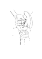
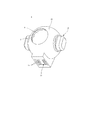
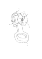
- FIG. 1 It is a perspective view of the main toy body in an example of a toy for describing an embodiment of the present invention. It is a perspective view of the main toy body of FIG. It is a perspective view of the sub toy body attached to the main toy body of FIG. It is a perspective view of the sub toy body of FIG. It is a block diagram which shows the functional structure of the toy of FIG. It is a flowchart of the process which the main toy body of FIG. 1 performs. It is a perspective view of the internal mechanism of the main toy body of FIG. It is a perspective view which shows operation
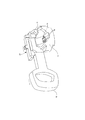
- FIGS. 1 and 2 show an example of a main toy body of a toy for explaining an embodiment of the present invention
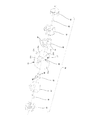
- FIGS. 3 and 4 show a toy side toy for explaining an embodiment of the present invention. A specific example is shown.
- the toy is composed of a main toy body 2 and a secondary toy body 3 that is detachably attached to the main toy body 2.
- the main toy body 2 is configured as a belt that can be attached to the user's waist
- the sub-toy body 3 is configured as a ball that can be gripped by the user.
- the main toy body 2 includes a buckle body 10, a cover 11 that covers the front surface of the buckle body 10, and a handle 12 as an operation unit.
- the cover 11 is supported by the buckle body 10 so as to be openable and closable so that the front surface of the buckle body 10 is exposed.
- An attachment portion 13 to which the sub toy body 3 is attached is provided on the front surface of the buckle body 10 that is exposed when the cover 11 is opened.
- the cover 11 is provided with a window 14 through which the secondary toy body 3 can be viewed from the outside of the cover 11 in a state where the secondary toy body 3 is attached to the attachment portion 13 and the cover 11 is closed.
- the handle 12 is supported by the buckle body 10 so as to be movable in the left-right direction along the waist while the main toy body 2 configured as a belt is attached to the user's torso, and is pulled out from the buckle body 10. In addition, it is operated so as to be pushed into the buckle body 10.
- the moving direction of the handle 12, that is, the operation unit is the left-right direction, but the present invention is not limited to this.
- a predetermined first direction and a second direction different from the first direction may be used.
- the sub-toy body 3 includes an outer shell 30 formed in a substantially spherical shape, a display unit 31 accommodated in the outer shell 30, a driven unit 32 that changes the display of the display unit 31, and a type information holding unit 33.
- the outer shell 30 is provided with a window 34 through which the display unit 31 can be viewed from the outside of the outer shell 30.
- the display unit 31 is visible through the window 34 and the window 14 provided in the cover 11 in a state where the sub-toy body 3 is attached to the attachment portion 13 of the main toy body 2 and the cover 11 of the main toy body 2 is closed. It is said.
- the display unit 31 is configured to be able to change the display visually recognized through the window 34. Details of the display unit 31 and the driven unit 32 that changes the display of the display unit 31 will be described later.
- the secondary toy body 3 is provided with a plurality of types with different combinations of display on the display unit 31, and the type information holding unit 33 holds type information corresponding to the type of the secondary toy body 3.
- the type information holding unit 33 includes a plurality of protrusions 35 provided in the lower part of the outer shell 30, and the type information is held by the number and arrangement of the protrusions 35.
- the attachment unit 13 of the main toy body 2 is provided with a type information acquisition unit 15 that acquires type information from the type information holding unit 33 of the sub toy body 3 attached to the attachment unit 13.
- the type information acquisition unit 15 includes a plurality of switch units 16 that are pressed by the protrusions 35 of the type information holding unit 33 as the auxiliary toy body 3 is attached to the attachment unit 13. The type information is acquired based on the number and arrangement of the switch units 16.
- the type information of the sub toy body 3 may be held in the type information holding unit 33 in an optically read form such as a barcode or a dot code, and uses an electromagnetic wave such as RFID (Radio Frequency IDentification). It may be held in the type information holding unit 33 in a form that is read in the above manner.
- the type information acquisition unit 15 of the main toy body 2 is provided with reading means corresponding to the type information holding form in the type information holding unit 33.
- the main toy body 2 has the operation
- movement part 17 which consists of light-emitting bodies, such as sounding bodies, such as a speaker, and LED (Light (Emitting) Diode), for example, and it is comprised so that the production using a sound, light, etc. can be output.
- movement part 17 which consists of light-emitting bodies, such as sounding bodies, such as a speaker, and LED (Light (Emitting) Diode), for example, and it is comprised so that the production using a sound, light, etc. can be output.
- As the output that can be output different effects are prepared for each type of the sub toy body 3, and the effect corresponding to the type of the sub toy body 3 attached to the attachment portion 13 depends on the operation on the handle 12. 2 is output.
- FIG. 5 shows the functional configuration of the toy 1.
- the main toy body 2 includes the handle 12 and the type information acquisition unit 15 as the operation unit described above, an operation unit 17 that outputs effects, an operation information storage unit 18, and an operation control unit 19.
- the operation unit 17 includes a sound generator such as a speaker and a light emitter such as a light emitting diode (LED), and outputs an effect using sound or light.
- a sound generator such as a speaker
- a light emitter such as a light emitting diode (LED)
- the operation information storage unit 18 includes a storage medium such as a ROM (Read Only Memory) or a RAM (Random Access Memory), for example, and stores a program executed by the operation control unit 19 and operation information of the operation unit 17. is doing.
- the operation information is stored in association with the type information of the sub toy body 3.
- the operation control unit 19 includes a processing device such as a microprocessor, and operates according to a program stored in the operation information storage unit 18. Then, the operation control unit 19 recognizes the type information acquired by the type information acquisition unit 15, reads out the operation information corresponding to the recognized type information from the operation information storage unit 18, and operates the operation unit based on the read operation information. 17 is operated.
- a processing device such as a microprocessor
- the motion information includes a transformation standby effect as a first effect, a transformation effect as a second effect, a deadly technique standby effect as a third effect, and a deadly technique activation effect as a fourth effect.
- the operation control unit 19 operates by selecting any one of the first to fourth effects according to the attachment of the sub-toy body 3 to the attachment unit 13 and the operation of the handle 12. The unit 17 is operated.
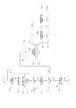
- FIG. 6 shows a flow of processing executed by the operation control unit 19.
- the operation control unit 19 of the main toy body 2 first detects the attachment of the sub toy body 3 to the attachment portion 13 (step S1). Attachment of the sub toy body 3 to the attachment portion 13 is detected by pressing one of the plurality of switch portions 16 provided in the type information acquisition portion 15 of the attachment portion 13, for example.
- step S1 When the attachment of the sub toy body 3 is detected (step S1: YES), the operation control unit 19 recognizes the type information of the attached sub toy body 3 and acquired by the type information acquisition unit 15. Then, the operation information corresponding to the recognized type information is read from the operation information storage unit 18 (step S3).
- the operation control unit 19 selects the transformation standby effect as the first effect included in the read operation information, and further operates the handle 12 (for example, the operation of pulling the handle 121 from the buckle body 10, the first direction Operation) is detected (step S5).
- the detection of the operation of the handle 12 is repeated.
- a transformation standby effect is output to the operation unit 17 (step S6). Note that the operation of the handle 12 is appropriately detected using, for example, a switch.
- the operation control unit 19 detects an operation of the handle 12 (for example, an operation of pushing the handle 12 into the buckle body 10, an operation in a second direction different from the first direction) (step S7).
- step S7 When the operation of the handle 12 is not detected (step S7: No), the operation control unit 19 detects the removal of the sub toy body 3 (step S8), and the handle 12 is detected until the removal of the sub toy body 3 is detected. The detection of the operation and the detection of the removal of the secondary toy body 3 are repeated.
- step S7 When the operation of the handle 12 is detected in step S7 (step S7: Yes), the operation control unit 19 refers to the flag M (step S9).
- the operation control unit 19 selects the transformation effect as the second effect and outputs the transformation effect to the operation unit 17 (step S10). ). Then, the operation control unit 19 sets the value of the flag M to “True” (step S11).
- step S7 When the operation of the handle 12 (for example, the operation of pulling out the handle 12 from the buckle body 10 or the operation in the first direction) is detected in step S7 after the transformation effect is output, the operation control unit 19 sets the flag. Reference is made to M (step S9). Since the value of the flag M is set to “True” in step S11, the operation control unit 19 subsequently refers to the flag N (step S12).
- the operation control unit 19 selects the special technique standby effect as the third effect and outputs the special technique standby effect to the operation unit 17. (Step S13). Then, the operation control unit 19 sets the value of the flag N to “True” (step S14).
- step S7 When an operation of the handle 12 (for example, an operation of pushing the handle 12 into the buckle body 10 or an operation in a second direction different from the first direction) is detected in step S7 after the special action standby effect is output.
- the operation control unit 19 refers to the flag M (step S9). Since the value of the flag M is set to “True” in step S11, the operation control unit 19 subsequently refers to the flag N (step S12).
- the operation control unit 19 selects the special technique activation effect as the fourth production, and sends the special technique activation effect to the operation unit 17. Output (step S15). Then, the operation control unit 19 sets the value of the flag N to “False” (step S16).
- step S7 every time the operation of the handle 12 is detected in step S7 (that is, every time the operation of pulling out the handle 12 from the buckle body 10 or the operation of pushing the handle 12 into the buckle body 10 is detected, that is, Each time an operation in the first direction or an operation in a second direction different from the first direction is detected), the motion control unit 19 refers to the flag N and performs the special technique standby effect and the special death.
- the technique activation effect is selected alternately, and the special technique standby effect and the special technique activation effect are alternately output to the operation unit 17.
- the sub-toy body 3 attached to the attachment portion 13 displays the display of the display portion 31 that is visually recognized through the window 34 as a predetermined operation of the handle 12. Change in degrees.
- a configuration for changing the display of the display unit 31 will be described.
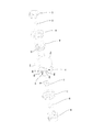
- FIGS. 9 and 10 show the configuration of the display unit 31 and the driven unit 32 of the sub toy body 3.
- the main toy body 2 is moved each time an operation for pulling out the handle 12 as an operation unit (operation in the first direction) and an operation for pushing in (operation in a second direction different from the first direction) are performed.
- the relay unit 20 is further included.
- the handle 12 is disposed on the side of the attachment portion 13 in the left-right direction, and the relay portion 20 is disposed on the rear side of the attachment portion 13 and extends in the left-right direction.
- the end of the relay unit 20 on the handle 12 side is connected to the handle 12, and the relay unit 20 is moved in the left-right direction integrally with the handle 12.
- the press part 21 is provided in the edge part on the opposite side to the handle
- FIG. The pressing portion 21 is disposed on the side opposite to the handle 12 side of the mounting portion 13, and from above the mounting portion 13 from the side of the mounting portion 13 as the handle 12 is pulled out from the buckle body 10. As the handle 12 is pushed into the buckle body 10, the handle 12 is retracted from above the attachment portion 13 to the side of the attachment portion 13.
- the display unit 31 of the secondary toy body 3 includes a plurality of display surfaces.
- four display surfaces 31a, 31b, 31c, and 31d are provided, and these display surfaces 31a, 31b, 31c, and 31d are arranged in a ring around the central axis A.
- the display surfaces 31a, 31b, 31c, and 31d are provided with different displays that are configured by a pattern or the like.
- the driven portion 32 includes a cam 36 that is rotated integrally with the display portion 31 around the central axis A, a first follower 40, and a second follower 41.
- the cam 36 includes a first cam portion 37 and a second cam portion. 38.
- the first cam portion 37 is provided with a plurality of cam surfaces 37a extending spirally around the central axis A, and the first cam portion 37 is formed in an annular and sawtooth wave shape coaxial with the central axis A as a whole. ing.
- the cam surfaces 37a are provided in the same number as the display surfaces in the display unit 31, and in the illustrated example, four cam surfaces 37a are provided at intervals of approximately 90 °.
- the second cam portion 38 is provided with a plurality of cam surfaces 38a extending spirally around the central axis A and a plurality of cam surfaces 38b extending in a spiral manner around the central axis A by being reversely wound around the cam surface 38a.
- the second cam portion 38 is formed in an annular and triangular wave shape that is coaxial with the central axis A as a whole.
- the cam surfaces 38a and the cam surfaces 38b are provided in the same number as the display surfaces in the display unit 31, and in the illustrated example, four cam surfaces are provided at intervals of approximately 90 °.
- the first follower 40 is disposed to face the first cam portion 37, and has a plurality of sliding portions 42 that can contact the cam surface 37a of the first cam portion 37, respectively.
- the first follower 40 is supported by the support frame 43 fixed to the outer shell 30 so as to be capable of translation along the central axis A.
- a cap 44 projecting outside the outer shell 30 is integrally fixed to the first follower 40, and the cap 44 is pushed along the central axis A into the outer shell 30, so that the first follower 40 is also moved to the central axis A.
- the sliding portion 42 of the first follower 40 abuts on the cam surface 37 a of the first cam portion 37.
- a spring 45 is interposed between the support frame 43 and the cap 44, and the cap 44 pushed into the outer shell 30 along the central axis A is urged in the opposite direction by the spring 45.
- the cap 44 is disposed to face the pressing portion 21 of the relay portion 20 of the main toy body 2.
- the handle 12 of the main toy body 2 is pulled out from the buckle body 10 and the pressing portion 21 is advanced above the mounting portion 13, the cap 44 engages with the pressing portion 21, and the outer shell 30 is pressed by the pressing portion 21. Is pushed into. Further, when the handle 12 is pushed into the buckle body 10 and the pressing portion 21 is retracted to the side of the attachment portion 13, the cap 44 biased by the spring 45 protrudes outside the outer shell 30.
- the relay unit 20 pushes the cap 44 into the outer shell 30 via the pressing unit 21 and again. It is reciprocated once with respect to the outer shell 30 so as to protrude to the outside of the outer shell 30.
- the second follower 41 is disposed so as to face the second cam portion 38, and has a plurality of sliding portions 46 that can come into contact with the cam surfaces 38a, 38b of the second cam portion 38, respectively.
- the second follower 41 is supported by the support frame 47 fixed to the outer shell 30 so as to be able to translate along the central axis A.
- a cap 48 is integrally fixed to the support frame 47, and a spring 49 as an urging member is interposed between the cap 48 and the second follower 41.
- the second follower 41 is urged toward the second cam portion 38 along the central axis A by the spring 49, and the sliding portion 46 of the second follower 41 is the cam surface 38a or the cam surface 38b of the second cam portion 38. Abut each.
- 11 to 14 show operations of the display unit 31 and the driven unit 32 of the sub toy body 3.
- the display given to the display surface 31a among the display surfaces 31a, 31b, 31c, 31d of the display unit 31 is visually recognized through the window 34 of the sub toy body 3.
- the sliding portion 46 of the second follower 41 is The second cam portion 38 is disposed on a cam surface 38b that passes over the cam surface 38a and continues to the cam surface 38a.
- the second follower 41 biased by the spring 49 is released as the contact between the sliding portion 42 of the first follower 40 and the cam surface 37 a of the first cam portion 37 is released.
- the sliding part 46 slides on the cam surface 38b of the second cam part 38 while rotating the cam 36, respectively.
- the cam 36 and the display unit 31 rotated integrally with the cam 36 are rotated by approximately 90 °, and the display surface facing the window 34 of the sub toy body 3 is switched from the display surface 31a to the display surface 31b.
- the display on the display unit 31 is changed.
- the relationship of the first follower 40 to the first cam portion 37 and the relationship of the second follower 41 to the second cam portion 38 are the same before and after the cam 36 is rotated by approximately 90 °. Therefore, every time the handle 12 is pulled out of the buckle body 10 and pushed into the buckle body 10 again, the cap 44 is pushed into the outer shell 30 and the sliding portion 42 of the first follower 40 is pushed. Slides on the cam surface 37a of the first cam portion 37 while rotating the cam 36, and as the cam 36 rotates, the sliding portion 46 of the second follower 41 moves along the central axis A. The cap 44 protrudes outward from the outer shell 30 again by sliding the cam surface 38a of the second cam portion 38 while retracting the second follower 41 toward the opposite side of the second cam portion 38 side.
- the display on the display unit 31 of the sub-toy body 3 can be changed for each predetermined operation on the handle 12 of the main toy body 2 (for example, for each reciprocal operation of pulling and pushing the handle 12).
- each time the handle 12 of the main toy body 2 is operated a different effect is output from the main toy body 2, so that the display of the display unit 31 of the sub toy body 3 changes and the toy's interest is enhanced. It can be further enhanced.
- the reciprocating “predetermined operation” in which the handle 12 is pulled out and pushed in again (the operation unit is operated in the first direction and then the second direction different from the first direction).
- the relay unit 20 drives the driven unit 32 once, and the driven unit 32 is rotated once by approximately 90 ° each time the driven unit 32 is driven once.
- the display surface facing the window 34 of the sub toy body 3 is sequentially switched so that the display of the display unit 31 viewed through the window 34 changes.
- the present invention is not limited to this embodiment. .
- the cap 44 is pushed into the outer shell 30 in the driven portion 32, and the sliding portion 42 of the first follower 40 slides on the cam surface 37 a of the first cam portion 37 while rotating the cam 36.
- the display unit 31 is rotated by approximately 90 °, and the display surface facing the window 34 of the sub toy body 3 is sequentially switched, and the display of the display unit 31 visually recognized through the window 34 is changed so that the handle 12 is pulled out.
- the relay unit 20 pushes the cap 44 into the outer shell 30 and the sliding portion 42 of the first follower 40 rotates the cam 36 every time the operation is performed (every operation in the first direction in the operation unit).
- the driven portion 32 is driven once so as to slide on the cam surface 37a of the first cam portion 37, and each time the driven portion 32 is driven once, the display portion 31 is substantially omitted. It is rotated 90 ° and faces the window 34 of the sub toy body 3
- the display surface may be sequentially switched, and the display of the display unit 31 visually recognized through the window 34 may be changed.
- “the cap 44 is pushed into the outer shell 30, and the sliding portion 42 of the first follower 40 slides on the cam surface 37 a of the first cam portion 37 while rotating the cam 36.
- the driven part is driven once “in the present invention, and the handle 12 is” drawn from the buckle body 10 (operation in the first direction) "in the present invention. This corresponds to “predetermined operation” in the operation unit.
Landscapes
- Physics & Mathematics (AREA)
- Engineering & Computer Science (AREA)
- Acoustics & Sound (AREA)
- Multimedia (AREA)
- Toys (AREA)
Abstract
【課題】興趣性が高い玩具を提供する 【解決手段】玩具は、主玩具体2と、主玩具体2に着脱可能に取り付けられる副玩具体3と、を備え、副玩具体3は、被駆動部32と、被駆動部32が1回駆動される毎に表示を変化させる表示部31と、を有し、主玩具体2は、操作部12と、主玩具体2に取り付けられた副玩具体3の被駆動部32に係合可能であり、操作部12において所定の操作がされる毎に被駆動部32を1回駆動する中継部20と、を有する。
Description
本発明は、玩具に関する。
特許文献1に記載された玩具は、操作部が設けられた中心部材と、中心部材と接続可能な周辺部材とからなり、操作部の操作に応じて周辺部材の収容空間の開口を閉鎖する閉鎖部材が開放状態とされる。
そして、特許文献1に記載された玩具においては、閉鎖部材が開放状態になるのに応じて、周辺部材の収容空間に収容された収容部材の演出手段が演出を実行するようになっている。演出として、特許文献1には、翼状の可動部材が弾性部材によって変形したり、発光部が発光したりすることが例示されている。
特許文献1に記載された玩具では、操作部が操作されて演出が実行された後、操作部が再び操作されても演出が再度実行されることはない。操作部の操作により一度実行された演出を再度実行させるには、再び周辺部材の閉鎖部材を閉鎖状態にして演出が出力される前の状態に戻す必要があり、興趣をそがれる。
本発明は、興趣性が高い玩具を提供することを目的とする。
本発明に係る玩具は、主玩具体と、前記主玩具体に着脱可能に取り付けられる副玩具体と、を備え、前記副玩具体は、被駆動部と、前記被駆動部が1回駆動される毎に表示を変化させる表示部と、を有し、前記主玩具体は、操作部と、当該主玩具体に取り付けられた前記副玩具体の前記被駆動部に係合可能であり、前記操作部において所定の操作がされる毎に前記被駆動部を1回駆動する中継部と、を有することを特徴とする。
また、本発明に係る玩具においては、前記主玩具体は、動作部と、前記動作部を動作させるための動作情報を記憶した動作情報記憶部と、前記操作部が操作される毎に、前記動作情報を前記動作情報記憶部から読み出し、読み出した前記動作情報に基づいて前記動作部を動作させる動作制御部と、をさらに有するようにしても良い。
また、本発明に係る玩具においては、前記表示部は、環状に並ぶ複数の表示面を含み、前記被駆動部が1回駆動される毎に複数の前記表示面の並びの中心軸まわりに所定角度回転されて表示を変化させてもよい。
また、本発明に係る玩具においては、前記被駆動部は、前記中心軸と同軸の環状且つのこぎり波状に形成された第1カム部、及び前記中心軸と同軸の環状且つ三角波状に形成された第2カム部を有し、前記表示部と一体に回転されるカムと、前記中継部の移動に応じて前記中心軸に沿って並進移動され、並進移動に伴って前記第1カム部を摺動する第1フォロアと、前記中心軸に沿って移動可能に設けられ、前記カムの回転に伴って前記第2カム部を摺動する第2フォロアと、前記第2フォロアを前記中心軸に沿って前記第2カム部に押し付ける付勢部材と、を含んでもよい。
また、本発明に係る玩具においては、前記副玩具体は、該副玩具体の種類情報を保持した情報保持部をさらに有し、前記主玩具体は、動作部と、該主玩具体に取り付けられた前記副玩具体の前記種類情報保持部から前記種類情報を取得する種類情報取得部と、前記動作部を動作させるための動作情報であって、前記種類情報に対応付けられる動作情報を記憶した動作情報記憶部と、前記種類情報取得部によって取得された前記種類情報に対応する前記動作情報を前記動作情報記憶部から読み出し、前記操作部が操作される毎に、読み出した前記動作情報に基づいて前記動作部を動作させる動作制御部と、をさらに有してもよい。
また、本発明に係る玩具においては、前記表示部は、環状に並ぶ複数の表示面を含み、前記被駆動部が1回駆動される毎に複数の前記表示面の並びの中心軸まわりに所定角度回転されて表示を変化させてもよい。
また、本発明に係る玩具においては、前記被駆動部は、前記中心軸と同軸の環状且つのこぎり波状に形成された第1カム部、及び前記中心軸と同軸の環状且つ三角波状に形成された第2カム部を有し、前記表示部と一体に回転されるカムと、前記中継部の移動に応じて前記中心軸に沿って並進移動され、並進移動に伴って前記第1カム部を摺動する第1フォロアと、前記中心軸に沿って移動可能に設けられ、前記カムの回転に伴って前記第2カム部を摺動する第2フォロアと、前記第2フォロアを前記中心軸に沿って前記第2カム部に押し付ける付勢部材と、を含んでもよい。
本発明によれば、興趣性が高い玩具を提供することができる。
図1及び図2は、本発明の実施形態を説明するための、玩具の主玩具体の一例を示し、図3及び図4は、本発明の実施形態を説明するための、玩具の副玩具体の一例を示す。
玩具は、主玩具体2と、主玩具体2に着脱可能に取り付けられる副玩具体3とからなる。主玩具体2は、使用者の腰部に装着可能なベルトとして構成されており、副玩具体3は、使用者が把持可能なボールとして構成されている。
主玩具体2は、バックル本体10と、バックル本体10の前面を覆うカバー11と、操作部としてのハンドル12とを有する。
カバー11は、バックル本体10の前面を露呈させるように、開閉可能にバックル本体10に支持されている。カバー11が開かれた状態で露呈するバックル本体10の前面には、副玩具体3が取り付けられる取付部13が設けられている。カバー11には、副玩具体3が取付部13に取り付けられ且つカバー11が閉じられた状態で、副玩具体3をカバー11の外側から覗かせる窓14が設けられている。
ハンドル12は、ベルトとして構成される主玩具体2が使用者の胴に装着された状態で胴囲に沿う左右方向に移動可能にバックル本体10に支持されており、バックル本体10から引き出され、またバックル本体10に押し込まれるように操作される。なお、本実施形態においては、ハンドル12、すなわち、操作部の移動方向を左右方向としたがこれに限られない。例えば、所定の第1方向と、当該第1方向とは異なる第2方向としてもよい。
副玩具体3は、略球形状に形成された外殻30と、外殻30に収容された表示部31と、表示部31の表示を変化させる被駆動部32と、種類情報保持部33とを有する。
外殻30には表示部31を外殻30の外側から覗かせる窓34が設けられている。副玩具体3が主玩具体2の取付部13に取り付けられ且つ主玩具体2のカバー11が閉じられた状態で、表示部31は、窓34及びカバー11に設けられた窓14を通して視認可能とされる。
表示部31は、窓34を通して視認される表示を変化可能に構成されている。表示部31及び表示部31の表示を変化させる被駆動部32の詳細については後述する。
副玩具体3は、表示部31の表示の組み合わせが互いに異なる複数の種類が用意されており、種類情報保持部33には副玩具体3の種類に対応する種類情報が保持されている。図示の例では、種類情報保持部33は、外殻30の下部に設けられた複数の突起35によって構成され、突起35の数及び配置によって種類情報が保持されている。
主玩具体2の取付部13には、取付部13に取り付けられた副玩具体3の種類情報保持部33から種類情報を取得する種類情報取得部15が設けられている。図示の例では、種類情報取得部15は、副玩具体3が取付部13に取り付けられるのに伴って種類情報保持部33の突起35によってそれぞれ押圧される複数のスイッチ部16によって構成され、押圧されたスイッチ部16の数及び配置によって種類情報を取得する。
なお、副玩具体3の種類情報は、例えばバーコードやドットコードなどの光学的に読み取られる形態で種類情報保持部33に保持されていてもよく、RFID(Radio Frequency IDentification)などの電磁波を用いて読み取られる形態で種類情報保持部33に保持されていてもよい。主玩具体2の種類情報取得部15には、種類情報保持部33における種類情報の保持形態に対応した読取手段が設けられる。
そして、主玩具体2は、例えばスピーカ等の発音体やLED(Light Emitting Diode)等の発光体からなる動作部17を有し、音声や光などを用いた演出を出力可能に構成されており、出力可能な演出として、副玩具体3の種類毎に異なる演出が用意され、取付部13に取り付けられている副玩具体3の種類に対応した演出がハンドル12に対する操作に応じて主玩具体2から出力される。
図5は、玩具1の機能的構成を示す。
主玩具体2は、上述した操作部としてのハンドル12及び種類情報取得部15と、演出を出力する動作部17と、動作情報記憶部18と、動作制御部19と、を備えている。
動作部17は、上述したとおり、例えばスピーカ等の発音体やLED(Light Emitting Diode)等の発光体を含み、音声や光を用いた演出を出力する。
動作情報記憶部18は、例えばROM(Read Only Memory)やRAM(Random Access Memory)などの記憶媒体を含んで構成され、動作制御部19によって実行されるプログラムや、動作部17の動作情報を記憶している。動作情報は、副玩具体3の種類情報に対応付けて記憶されている。
動作制御部19は、例えばマイクロプロセッサなどの処理装置を含み、動作情報記憶部18に記憶されたプログラムに従って動作する。そして、動作制御部19は、種類情報取得部15によって取得された種類情報を認識し、認識した種類情報に応じた動作情報を動作情報記憶部18から読み出し、読み出した動作情報に基づいて動作部17を動作させる。
本例において、動作情報には、第1演出としての変身待機演出と、第2演出としての変身演出と、第3演出としての必殺技待機演出と、第4演出としての必殺技発動演出とが含まれるものとし、動作制御部19は、取付部13に対する副玩具体3の取り付けやハンドル12の操作に応じて、第1演出~第4演出のうちのいずれか一つの演出を選択して動作部17を動作させる。
図6は、動作制御部19が実行する処理のフローを示す。
主玩具体2の動作制御部19は、まず、取付部13に対する副玩具体3の取り付けを検出する(ステップS1)。取付部13に対する副玩具体3の取り付けは、例えば取付部13の種類情報取得部15に設けられた複数のスイッチ部16のいずれかが押圧されることによって検出される。
副玩具体3の取り付けを検出した場合に(ステップS1:YES)、動作制御部19は、取り付けられた副玩具体3の種類情報であって種類情報取得部15によって取得された種類情報を認識し(ステップS2)、認識した種類情報に対応した動作情報を動作情報記憶部18から読み出す(ステップS3)。
併せて、動作制御部19は、読み出した動作情報に含まれる第1~第4演出の選択に用いられるフラッグM,Nを初期化(M=False、N=False)する(ステップS4)。
そして、動作制御部19は、読み出した動作情報に含まれる第1演出としての変身待機演出を選択し、さらに、ハンドル12の操作(例えば、ハンドル121をバックル本体10から引き出す操作、第1の方向への操作)を検出する(ステップS5)。ハンドル12の操作が検出されない場合(ステップS5:No)、ハンドル12の操作の検出を繰り返す。ハンドル12の操作が検出されると(ステップS5:Yes)、変身待機演出を動作部17に出力させる(ステップS6)。なお、ハンドル12の操作は、例えばスイッチなどを用いて適宜検出される。
次いで、動作制御部19は、ハンドル12の操作(例えば、ハンドル12をバックル本体10に押し込む操作、第1の方向とは異なる第2の方向への操作)を検出する(ステップS7)。
ハンドル12の操作が検出されない場合に(ステップS7:No)、動作制御部19は、副玩具体3の取り外しを検出し(ステップS8)、副玩具体3の取り外しが検出されるまで、ハンドル12の操作の検出及び副玩具体3の取り外しの検出を繰り返す。
上記ステップS7にてハンドル12の操作を検出した場合に(ステップS7:Yes)、動作制御部19はフラッグMを参照する(ステップS9)。
フラッグMの値が上記ステップS4にて設定された“False”であるものとして、動作制御部19は、第2演出としての変身演出を選択し、変身演出を動作部17に出力させる(ステップS10)。そして、動作制御部19は、フラッグMの値を“True”に設定する(ステップS11)。
変身演出が出力された後に、ステップS7にてハンドル12の操作(例えば、ハンドル12をバックル本体10から引き出す操作、第1の方向への操作)を検出した場合に、動作制御部19は、フラッグMを参照する(ステップS9)。上記ステップS11にてフラッグMの値が“True”に設定されていることから、動作制御部19は、続いてフラッグNを参照する(ステップS12)。
フラッグNの値が上記ステップS4にて設定された“False”であるものとして、動作制御部19は、第3演出としての必殺技待機演出を選択し、必殺技待機演出を動作部17に出力させる(ステップS13)。そして、動作制御部19は、フラッグNの値を“True”に設定する(ステップS14)。
必殺技待機演出が出力された後に、ステップS7にてハンドル12の操作(例えば、ハンドル12をバックル本体10に押し込む操作、第1の方向とは異なる第2の方向への操作)を検出した場合に、動作制御部19は、フラッグMを参照する(ステップS9)。上記ステップS11にてフラッグMの値が“True”に設定されていることから、動作制御部19は、続いてフラッグNを参照する(ステップS12)。
さらに上記ステップS14にてフラッグNの値が“True”に設定されていることから、動作制御部19は、第4演出としての必殺技発動演出を選択し、必殺技発動演出を動作部17に出力させる(ステップS15)。そして、動作制御部19は、フラッグNの値を“False”に設定する(ステップS16)。
以後、ステップS7にてハンドル12の操作を検出する毎に(すなわち、ハンドル12をバックル本体10から引き出す操作、または、ハンドル12をバックル本体10に押し込む操作のいずれかを検出する毎に、つまり、第1の方向への操作、または、第1の方向とは異なる第2の方向への操作を検出する毎に)、動作制御部19は、フラッグNを参照して、必殺技待機演出と必殺技発動演出とを交互に選択し、必殺技待機演出と必殺技発動演出とを交互に動作部17に出力させる。
以上のハンドル12の操作に応じた演出出力の処理に併せて、取付部13に取り付けられている副玩具体3は、窓34を通して視認される表示部31の表示をハンドル12の所定の操作の度に変化させる。以下、表示部31の表示を変化させる構成について説明する。
図7及び図8は、主玩具体2の内部機構を示し、図9及び図10は、副玩具体3の表示部31及び被駆動部32の構成を示す。
主玩具体2は、操作部としてのハンドル12を引き出す操作(第1の方向への操作)および押し込む操作(第1の方向とは異なる第2の方向への操作)がされる度に移動される中継部20をさらに有する。ハンドル12は、左右方向に取付部13の側方に配置されており、中継部20は、取付部13の後側に配置され、左右方向に延びている。中継部20のハンドル12側の端部はハンドル12に連結されており、中継部20はハンドル12と一体に左右方向に移動される。
そして、中継部20のハンドル12側とは反対側の端部には押圧部21が設けられている。押圧部21は、取付部13のハンドル12側とは反対側の側方に配置されており、ハンドル12がバックル本体10から引き出されるのに伴って取付部13の側方から取付部13の上方に前進され、ハンドル12がバックル本体10に押し込まれるのに伴って取付部13の上方から取付部13の側方に後退される。
副玩具体3の表示部31は、複数の表示面を含む。図示の例では四つの表示面31a,31b,31c,31dが設けられており、これらの表示面31a,31b,31c,31dが中心軸Aまわりに環状に並べられて構成されている。表示面31a,31b,31c,31dには、絵柄などによって構成される互いに異なる表示が施されている。
被駆動部32は、中心軸Aまわりに表示部31と一体に回転されるカム36と、第1フォロア40及び第2フォロア41とを含み、カム36は第1カム部37と第2カム部38とを有する。
第1カム部37には、中心軸Aまわりに螺旋状に延びる複数のカム面37aが設けられており、第1カム部37は、全体として中心軸Aと同軸の環状且つのこぎり波状に形成されている。カム面37aは、表示部31における表示面と同数設けられ、図示の例では、略90°おきに四つ設けられている。
第2カム部38には、中心軸Aまわりに螺旋状に延びる複数のカム面38a及びカム面38aとは逆巻きで中心軸Aまわりに螺旋状に延びる複数のカム面38bが交互に設けられており、第2カム部38は、全体として中心軸Aと同軸の環状且つ三角波状に形成されている。カム面38a及びカム面38bは、それぞれ表示部31における表示面と同数設けられ、図示の例では、略90°おきに四つずつ設けられている。
第1フォロア40は、第1カム部37に対向して配置されており、第1カム部37のカム面37aにそれぞれ当接可能な複数の摺動部42を有する。そして、第1フォロア40は、外殻30に固定される支持枠43によって中心軸Aに沿って並進移動可能に支持されている。
第1フォロア40には外殻30の外側に突出するキャップ44が一体に固定され、キャップ44が中心軸Aに沿って外殻30に押し込まれることにより、第1フォロア40もまた中心軸Aに沿って第1カム部37側に移動され、第1フォロア40の摺動部42が第1カム部37のカム面37aにそれぞれ当接する。
支持枠43とキャップ44との間にはバネ45が介装されており、中心軸Aに沿って外殻30に押し込まれたキャップ44はバネ45によって反対方向に付勢される。
副玩具体3が主玩具体2の取付部13に取り付けられた状態で、キャップ44は主玩具体2の中継部20の押圧部21に対向して配置される。そして、主玩具体2のハンドル12がバックル本体10から引き出されて押圧部21が取付部13の上方に前進されると、キャップ44は押圧部21と係合し、押圧部21によって外殻30に押し込まれる。また、ハンドル12がバックル本体10に押し込まれて押圧部21が取付部13の側方に後退されると、バネ45によって付勢されたキャップ44は外殻30の外側に突出する。つまり、主玩具体2のハンドル12においてバックル本体10から引き出されて、再び押し込まれる操作がされる毎に、中継部20は、押圧部21を介して、キャップ44を外殻30に押し込み、再び外郭30の外側に突出させるというように、外郭30に対して1回往復移動させる。
第2フォロア41は第2カム部38に対向して配置されており、第2カム部38のカム面38a,38bにそれぞれ当接可能な複数の摺動部46を有する。そして、第2フォロア41は、外殻30に固定される支持枠47によって中心軸Aに沿って並進移動可能に支持されている。
また、支持枠47にはキャップ48が一体に固定され、キャップ48と第2フォロア41との間には付勢部材としてのバネ49が介装されている。第2フォロア41はバネ49によって中心軸Aに沿って第2カム部38側に付勢されており、第2フォロア41の摺動部46は第2カム部38のカム面38a又はカム面38bにそれぞれ当接する。
図11から図14は、副玩具体3の表示部31及び被駆動部32の動作を示す。
図11に示す状態において、表示部31の表示面31a,31b,31c,31dのうち、表示面31aに施された表示が副玩具体3の窓34を通して視認されるものとする。
図12に示すように、主玩具体2のハンドル12がバックル本体10から引き出され、キャップ44が外殻30に押し込まれると、第1フォロア40の摺動部42は、カム36を回転させながら、第1カム部37のカム面37aをそれぞれ摺動する。
カム36が回転されるのに伴い、第2フォロア41の摺動部46は、中心軸Aに沿って第2カム部38側とは反対側に向けて第2フォロア41を後退させながら、第2カム部38のカム面38aをそれぞれ摺動する。
図13に示すように、主玩具体2のハンドル12がバックル本体10から完全に引き出され、キャップ44が外殻30に完全に押し込まれた時点で、第2フォロア41の摺動部46は、第2カム部38のカム面38aを乗り越え、カム面38aに連なるカム面38b上に配置される。
そして、主玩具体2のハンドル12がバックル本体10に押し込まれ、バネ45によって付勢されたキャップ44が外殻30の外側に突出すると、キャップ44と一体に移動される第1フォロア40の摺動部42と第1カム部37のカム面37aとの当接が解除される。
図14に示すように、第1フォロア40の摺動部42と第1カム部37のカム面37aとの当接が解除されるのに伴い、バネ49によって付勢された第2フォロア41の摺動部46は、カム36を回転させながら、第2カム部38のカム面38bをそれぞれ摺動する。
以上により、カム36及びカム36と一体に回転される表示部31は略90°回転され、副玩具体3の窓34を臨む表示面が表示面31aから表示面31bに切り替わり、窓34を通して視認される表示部31の表示が変化する。
そして、第1カム部37に対する第1フォロア40の関係、及び第2カム部38に対する第2フォロア41の関係は、カム36が略90°回転される前と後とで同じとなっている。よって、バックル本体10から引き出され、再びバックル本体10に押し込まれるというようなハンドル12における所定の操作がされる毎に、キャップ44が外殻30に押し込まれ、第1フォロア40の摺動部42がカム36を回転させながら、第1カム部37のカム面37aを摺動していき、カム36が回転されるのに伴い、第2フォロア41の摺動部46は、中心軸Aに沿って第2カム部38側とは反対側に向けて第2フォロア41を後退させながら、第2カム部38のカム面38aを摺動し、再びキャップ44が外殻30から外側に突出することで、キャップ44と一体に移動される第1フォロア40の摺動部42と第1カム部37のカム面37aとの当接が解除され、これに伴い、バネ49によって付勢された第2フォロア41の摺動部46が、カム36を回転させながら、第2カム部38のカム面38bをそれぞれ摺動する、という被駆動部32における1回の駆動が行なわれ、この1回の駆動によって、表示部31が略90°回転されて副玩具体3の窓34を臨む表示面が順次切り替わり、窓34を通して視認される表示部31の表示が変化する。つまり、この実施形態において、「キャップ44が外殻30に押し込まれ、第1フォロア40の摺動部42がカム36を回転させながら、第1カム部37のカム面37aを摺動していき、カム36が回転されるのに伴い、第2フォロア41の摺動部46は、中心軸Aに沿って第2カム部38側とは反対側に向けて第2フォロア41を後退させながら、第2カム部38のカム面38aを摺動し、再びキャップ44が外殻30から外側に突出することで、キャップ44と一体に移動される第1フォロア40の摺動部42と第1カム部37のカム面37aとの当接が解除され、これに伴い、バネ49によって付勢された第2フォロア41の摺動部46が、カム36を回転させながら、第2カム部38のカム面38bをそれぞれ摺動すること」が、本発明にいう「被駆動部が1回駆動される」ことに相当し、ハンドル12が「バックル本体10から引き出され、再びバックル本体10に押し込まれること」が、本発明にいう操作部における「所定の操作」に相当する。
このように、主玩具体2のハンドル12における所定の操作毎に(例えば、ハンドル12を引き出し、押し込むという1往復の操作毎に)、副玩具体3の表示部31の表示を変化させることができ、玩具の興趣性を高めることができる。さらに、主玩具体2のハンドル12の操作毎に、主玩具体2から異なる演出が出力されるので、副玩具体3の表示部31の表示が変化するのと合わさって、玩具の興趣性を一層高めることができる。
なお、本実施形態においては、ハンドル12が引き出され、再び押し込まれるという1往復の「所定の操作」(操作部が第1の方向へ操作され、その後、第1の方向とは異なる第2の方向へ操作されるという「所定の操作」)毎に、中継部20が被駆動部32を1回駆動し、被駆動部32が1回駆動される毎に、表示部31が略90°回転されて副玩具体3の窓34を臨む表示面が順次切り替わり、窓34通して視認される表示部31の表示が変化するようにしているが、本発明はこの実施形態に限られるものではない。例えば、被駆動部32においてキャップ44が外殻30に押し込まれ、第1フォロア40の摺動部42がカム36を回転させながら、第1カム部37のカム面37aを摺動していくことで、表示部31が略90°回転されて副玩具体3の窓34を臨む表示面が順次切り替わり、窓34を通して視認される表示部31の表示が変化するようにして、ハンドル12が引き出される操作1回毎に(操作部における第1の方向への操作毎に)、中継部20が、キャップ44を外殻30に押し込み、第1フォロア40の摺動部42がカム36を回転させながら、第1カム部37のカム面37aを摺動していくように、被駆動部32を1回駆動し、このように被駆動部32が1回駆動される毎に、表示部31が略90°回転されて副玩具体3の窓34を臨む表示面が順次切り替わり、窓34通して視認される表示部31の表示が変化するようにしてもよい。この実施形態においては、「キャップ44が外殻30に押し込まれ、第1フォロア40の摺動部42がカム36を回転させながら、第1カム部37のカム面37aを摺動していくこと」が、本発明にいう「被駆動部が1回駆動される」ことに相当し、ハンドル12が「バックル本体10から引き出されること(第1の方向への操作)」が、本発明にいう操作部における「所定の操作」に相当する。
1 玩具
2 主玩具体
3 副玩具体
10 バックル本体
11 カバー
12 ハンドル(操作部)
13 取付部
15 種類情報取得部
17 動作部
18 動作情報記憶部
19 動作制御部
20 中継部
31 表示部
31a,31b,31c,31d 表示面
32 被駆動部
33 種類情報保持部
36 カム
37 第1カム部
38 第2カム部
40 第1フォロア
41 第2フォロア
49 バネ(付勢部材)
2 主玩具体
3 副玩具体
10 バックル本体
11 カバー
12 ハンドル(操作部)
13 取付部
15 種類情報取得部
17 動作部
18 動作情報記憶部
19 動作制御部
20 中継部
31 表示部
31a,31b,31c,31d 表示面
32 被駆動部
33 種類情報保持部
36 カム
37 第1カム部
38 第2カム部
40 第1フォロア
41 第2フォロア
49 バネ(付勢部材)
Claims (7)
- 主玩具体と、
前記主玩具体に着脱可能に取り付けられる副玩具体と、
を備え、
前記副玩具体は、
被駆動部と、
前記被駆動部が1回駆動される毎に表示を変化させる表示部と、
を有し、
前記主玩具体は、
操作部と、
該主玩具体に取り付けられた前記副玩具体の前記被駆動部に係合可能であり、前記操作部において所定の操作がされる毎に前記被駆動部を1回駆動する中継部と、
を有する玩具。 - 請求項1記載の玩具であって、
前記主玩具体は、
動作部と、前記動作部を動作させるための動作情報を記憶した動作情報記憶部と、
前記操作部が操作される毎に、前記動作情報を前記動作情報記憶部から読み出し、読み出した前記動作情報に基づいて前記動作部を動作させる動作制御部と、
をさらに有する玩具。 - 請求項1または2記載の玩具であって、
前記表示部は、環状に並ぶ複数の表示面を含み、前記被駆動部が1回駆動される毎に複数の前記表示面の並びの中心軸まわりに所定角度回転されて表示を変化させる玩具。 - 請求項3記載の玩具であって、
前記被駆動部は、
前記中心軸と同軸の環状且つのこぎり波状に形成された第1カム部、及び前記中心軸と同軸の環状且つ三角波状に形成された第2カム部を有し、前記表示部と一体に回転されるカムと、
前記中継部の移動に応じて前記中心軸に沿って並進移動され、並進移動に伴って前記第1カム部を摺動する第1フォロアと、
前記中心軸に沿って移動可能に設けられ、前記カムの回転に伴って前記第2カム部を摺動する第2フォロアと、
前記第2フォロアを前記中心軸に沿って前記第2カム面に押し付ける付勢部材と、
を含む玩具。 - 請求項1記載の玩具であって、
前記副玩具体は、該副玩具体の種類情報を保持した種類情報保持部をさらに有し、
前記主玩具体は、
動作部と、
該主玩具体に取り付けられた前記副玩具体の前記種類情報保持部から前記種類情報を取得する種類情報取得部と、
前記動作部を動作させるための動作情報であって、前記種類情報に対応付けられた動作情報を記憶した動作情報記憶部と、
前記種類情報取得部によって取得された前記種類情報に対応する前記動作情報を前記動作情報記憶部から読み出し、前記操作部が操作される毎に、読み出した前記動作情報に基づいて前記動作部を動作させる動作制御部と、
をさらに有する玩具。 - 請求項5記載の玩具であって、
前記表示部は、環状に並ぶ複数の表示面を含み、前記被駆動部が1回駆動される毎に複数の前記表示面の並びの中心軸まわりに所定角度回転されて表示を変化させる玩具。 - 請求項6記載の玩具であって、
前記被駆動部は、
前記中心軸と同軸の環状且つのこぎり波状に形成された第1カム部、及び前記中心軸と同軸の環状且つ三角波状に形成された第2カム部を有し、前記表示部と一体に回転されるカムと、
前記中継部の移動に応じて前記中心軸に沿って並進移動され、並進移動に伴って前記第1カム部を摺動する第1フォロアと、
前記中心軸に沿って移動可能に設けられ、前記カムの回転に伴って前記第2カム部を摺動する第2フォロアと、
前記第2フォロアを前記中心軸に沿って前記第2カム面に押し付ける付勢部材と、
を含む玩具。
Priority Applications (1)
| Application Number | Priority Date | Filing Date | Title |
|---|---|---|---|
| CN201680036602.XA CN107708828B (zh) | 2015-07-14 | 2016-06-03 | 玩具 |
Applications Claiming Priority (2)
| Application Number | Priority Date | Filing Date | Title |
|---|---|---|---|
| JP2015140896A JP5995299B1 (ja) | 2015-07-14 | 2015-07-14 | 玩具 |
| JP2015-140896 | 2015-07-14 |
Publications (1)
| Publication Number | Publication Date |
|---|---|
| WO2017010187A1 true WO2017010187A1 (ja) | 2017-01-19 |
Family
ID=56960896
Family Applications (1)
| Application Number | Title | Priority Date | Filing Date |
|---|---|---|---|
| PCT/JP2016/066554 Ceased WO2017010187A1 (ja) | 2015-07-14 | 2016-06-03 | 玩具 |
Country Status (3)
| Country | Link |
|---|---|
| JP (1) | JP5995299B1 (ja) |
| CN (2) | CN111437613B (ja) |
| WO (1) | WO2017010187A1 (ja) |
Families Citing this family (5)
| Publication number | Priority date | Publication date | Assignee | Title |
|---|---|---|---|---|
| JP6660916B2 (ja) * | 2017-05-31 | 2020-03-11 | 株式会社バンダイ | 演出出力玩具 |
| JP6494838B1 (ja) * | 2018-06-01 | 2019-04-03 | 株式会社バンダイ | 動作玩具 |
| JP7224965B2 (ja) * | 2019-03-05 | 2023-02-20 | 株式会社バンダイ | 動作玩具 |
| JP7250861B2 (ja) * | 2020-05-22 | 2023-04-03 | 株式会社バンダイ | 演出出力玩具 |
| JP7225186B2 (ja) * | 2020-12-02 | 2023-02-20 | 株式会社バンダイ | 演出出力玩具 |
Citations (6)
| Publication number | Priority date | Publication date | Assignee | Title |
|---|---|---|---|---|
| JP2004329770A (ja) * | 2003-05-12 | 2004-11-25 | Tomy Co Ltd | 動作玩具 |
| JP2006346220A (ja) * | 2005-06-16 | 2006-12-28 | Konami Digital Entertainment:Kk | 遊戯玩具 |
| JP2012115504A (ja) * | 2010-12-01 | 2012-06-21 | Bandai Co Ltd | 玩具 |
| JP2013111474A (ja) * | 2011-11-24 | 2013-06-10 | Bandai Co Ltd | 化粧玩具および化粧玩具用装着体 |
| JP2014004316A (ja) * | 2012-06-26 | 2014-01-16 | Bandai Co Ltd | 動作応答玩具および玩具体 |
| JP2014155870A (ja) * | 2010-12-21 | 2014-08-28 | Bandai Co Ltd | 読取体 |
Family Cites Families (7)
| Publication number | Priority date | Publication date | Assignee | Title |
|---|---|---|---|---|
| CN1048569C (zh) * | 1994-04-29 | 2000-01-19 | 宁波市东方机芯总厂 | 八音琴的动力外输机构 |
| JPH10156050A (ja) * | 1996-11-28 | 1998-06-16 | Pilot Ink Co Ltd | 形跡表示玩具 |
| KR200323144Y1 (ko) * | 2003-01-14 | 2003-08-14 | 박경화 | 회전형 자석 접합장치 및 이를 구비한 조립식 완구 |
| US7275975B2 (en) * | 2005-06-03 | 2007-10-02 | Mattel, Inc. | Toy vehicle with on-board electronics |
| CN201632047U (zh) * | 2009-12-31 | 2010-11-17 | 东莞市智乐堡儿童玩具有限公司 | 多功能儿童玩具车 |
| CN201710972U (zh) * | 2010-02-02 | 2011-01-19 | 景嘉有限公司 | 射频双向模式玩具控制设定系统 |
| JP5531149B1 (ja) * | 2013-08-23 | 2014-06-25 | 株式会社バンダイ | 演出出力玩具 |
-
2015
- 2015-07-14 JP JP2015140896A patent/JP5995299B1/ja active Active
-
2016
- 2016-06-03 CN CN202010267873.4A patent/CN111437613B/zh active Active
- 2016-06-03 WO PCT/JP2016/066554 patent/WO2017010187A1/ja not_active Ceased
- 2016-06-03 CN CN201680036602.XA patent/CN107708828B/zh active Active
Patent Citations (6)
| Publication number | Priority date | Publication date | Assignee | Title |
|---|---|---|---|---|
| JP2004329770A (ja) * | 2003-05-12 | 2004-11-25 | Tomy Co Ltd | 動作玩具 |
| JP2006346220A (ja) * | 2005-06-16 | 2006-12-28 | Konami Digital Entertainment:Kk | 遊戯玩具 |
| JP2012115504A (ja) * | 2010-12-01 | 2012-06-21 | Bandai Co Ltd | 玩具 |
| JP2014155870A (ja) * | 2010-12-21 | 2014-08-28 | Bandai Co Ltd | 読取体 |
| JP2013111474A (ja) * | 2011-11-24 | 2013-06-10 | Bandai Co Ltd | 化粧玩具および化粧玩具用装着体 |
| JP2014004316A (ja) * | 2012-06-26 | 2014-01-16 | Bandai Co Ltd | 動作応答玩具および玩具体 |
Non-Patent Citations (1)
| Title |
|---|
| "Omocha Shokai Henshin Belt DX Ghost Driver, Kamen Rider Omocha Site", BANDAI KOSHIKI SITE, 10 August 2016 (2016-08-10), pages 1 - 2, XP055345385, Retrieved from the Internet <URL:http://rider.b-boys.jp/products/cat1_1> * |
Also Published As
| Publication number | Publication date |
|---|---|
| JP5995299B1 (ja) | 2016-09-21 |
| CN107708828A (zh) | 2018-02-16 |
| JP2017018509A (ja) | 2017-01-26 |
| CN111437613A (zh) | 2020-07-24 |
| CN111437613B (zh) | 2021-08-06 |
| CN107708828B (zh) | 2020-05-01 |
Similar Documents
| Publication | Publication Date | Title |
|---|---|---|
| JP5995299B1 (ja) | 玩具 | |
| CN112090091B (zh) | 演出输出玩具 | |
| CN106816336B (zh) | 按钮开关 | |
| KR101931458B1 (ko) | 연출 완구 | |
| JP5939691B2 (ja) | 応答玩具および主玩具体 | |
| CN107073346A (zh) | 具有手动操作的扫描器的玩具系统 | |
| JP7177206B2 (ja) | 玩具 | |
| JP2017018609A (ja) | 玩具 | |
| US9679176B2 (en) | Indicia decoding device with security lock | |
| KR101628881B1 (ko) | 조립 완구 | |
| JP2016137403A (ja) | 応答玩具および主玩具体 | |
| US12079685B2 (en) | Systems, methods, and apparatuses for imaging using a dual-purpose illuminator | |
| US7399135B2 (en) | Pen with flashy barrel | |
| JP7117429B2 (ja) | 応答玩具および主玩具体 | |
| JP2017018609A5 (ja) | ||
| JP2025074267A (ja) | 動作玩具 | |
| JP6686059B2 (ja) | 応答玩具および主玩具体 | |
| JP2005334514A (ja) | 磁石を利用した移動玩具 | |
| KR20160119723A (ko) | 단말 거치용 고정부 구조 및 이를 이용한 차량용 거치대 | |
| TH185014S (th) | หลอดลิปสติก | |
| TH185015S (th) | หลอดลิปสติก | |
| TH79006S (th) | ฝาห่วงดึง |
Legal Events
| Date | Code | Title | Description |
|---|---|---|---|
| 121 | Ep: the epo has been informed by wipo that ep was designated in this application |
Ref document number: 16824167 Country of ref document: EP Kind code of ref document: A1 |
|
| NENP | Non-entry into the national phase |
Ref country code: DE |
|
| 122 | Ep: pct application non-entry in european phase |
Ref document number: 16824167 Country of ref document: EP Kind code of ref document: A1 |